Embed Size (px)
Citation preview

35.0
N STREET, N.W.
15
0.0
15
0.0
35.0
107
SCALE: 1:20
0 10 30 10060
DISTRICT OF COLUMBIA GOVERNMENT
OFFICE OF THE SURVEYOR
SR-20-01668(2019)
Washington, D.C., December 18, 2019
Plat for Building Permit of: SQUARE 1218 LOT 107
Furnished to: DAVID C. LANDSMAN
Surveyor, D.C.
Receipt No. 20-01668 Drawn by: A.S.
Scale: 1 inch = 20 feet
Recorded in Book 215 Page 106
I hereby certify that on this plat on which the Office of the Surveyor has drawn the dimensions of this lot, Ihave accurately and completely depicted and labeled the following:1) all existing buildings and improvements - including parking spaces, covered porches, decks andretaining walls over four feet above grade, and any existing face-on-line or party wall labeled as such, wellas projections and improvements in public space - with complete and accurate dimensions;2) all proposed demolition or raze of existing buildings duly labeled as such; all proposed buildings andimprovements - including parking spaces, covered porches, decks and retaining walls over four feet abovegrade, any existing face-on-line or party wall labeled as such, as well as projections and improvements inpublic space and the improvements used to satisfy pervious surface or green area ratio requirements - withcomplete and accurate dimensions, in conformity with the plans submitted with building permitapplication _________________________; and3) any existing chimney or vent on an adjacent property that is located within 10 feet of this lot.I also hereby certify that:1) my depiction on this plat, as detailed above, is accurate and complete as of the date of my signaturehereon;2) there is no elevation change exceeding ten feet measured between lot lines; or if so, this elevationchange is depicted on a site plan submitted with the plans for this permit application;3) I have/have not (circle one) filed a subdivision application with the Office of the Surveyor;4) I have/have not (circle one) filed a division of lots application with the Office of Tax & Revenue; and5) if there are changes to the lot and its boundaries as shown on this plat, or to the proposed constructionand plans as shown on this plat, that I shall obtain an updated plat from the Office of the Surveyor onwhich I will depict all existing and proposed construction and which I will then submit to the Office of theZoning Administrator for review and approval prior to permit issuance.Plats issued by the Office of the Surveyor will be valid for a period of two years from the date of issuance.I acknowledge that any inaccuracy or errors in my depiction on this plat will subject any permit orcertificate of occupancy issued in reliance on this plat to enforcement, including revocation under Sections105.6(1) and 110.5.2 of the Building Code (Title 12A of the DCMR) as well as prosecution and penaltiesunder Section 404 of D.C. Law 4-164 (D.C. Official Code §22-2405).
Signature: ____________________________________________ Date: ____________________
Printed Name: _______________________________ Relationship to Lot Owner:_______________
If a registered design professional, provide license number _____________ and include stamp below.
“I hereby certify that the dimensions and configuration of the lot(s)hereon depicted are consistent with the records of the Office of theSurveyor unless otherwise noted, but may not reflect actual fieldmeasurements. The dimensions and configuration of A&T lots areprovided by the Office of Tax and Revenue and may not necessarilyagree with the deed description(s).”
D
A
V
I
D
C
.
LAN
D
S
M
A
N
A
I
B
M
U
L
O
CF
O
T
C
I
R
T
S
I
D
LIVI
C
PE906954
P
R
O
F
E
S
S
I
O
NA
L
E
N
G
I
N
E
E
R
David C. Landsman Agent/Engineer
PE906954
April 28, 2020
Notes:
1. All proposed demolition or raze of existing
buildings is omitted for clarity, refer to
Sheet CIV100 and CIV101 for additional
details.
2. Existing chimneys and/or vents on adjacent
properties within 10 feet of the subject
property are not shown. Not applicable to
project scope or reviews, and these
locations are inaccessible.
3. Existing conditions shown hereon are
based upon a survey completed in
February, 2017.
B2007530
For:
NO
T FO
R C
ON
STR
UC
TIO
N
N S
tre
et
Re
side
nc
e32
34 N
St.
NW
Wa
shin
gto
n D
C 2
0007
© T
HO
MSO
N&
CO
OKE
Arc
hite
cts
pllc
CD Release #101-15-2019
CD Revision 103-19-2019
CD Release #207-07-2019
CD Release #307-23-2019
80% CD Release09-06-2019
90% CD Release10-04-2019
95% CD Release10-30-2019
96% CD Release12-20-2019
Electrical Release02-10-2020
97% CD Release02-11-2020
98% CD Release03-02-2020
99% DRAFT03-12-2020
A/C Air Condition(er, ing, ed ) D Drain, Dryer GWB Gypsum Wall Board NIC Not in Contract SIM SimilarAB Anchor Bolt DBL Double GYP Gypsum NO Number SK Addendum Sheet
ABV Above DEM Demolition HB Hose Bibb NOM Nominal SP Stand PipeAD Area Drain DET Detail HD Head NTS Not to Scale SPEC Specification
ADJ Adjustable DIA Diameter HDR Header O Oven SQ SquareAFF Above Finish Floor DIAG Diagonal HDWD Hardwood OC On Center SS Stainless Steel
AGG Aggregate DIFF Diffuser HDWR Hardware OD Outside Diameter ST StreetAHU Air Handling Unit DIM Dimension HGR Hanger OFF Office STD Standard
ALUM Aluminum DISP Dispenser HORIZ Horizontal OPNG Opening STL SteelANOD Anodized DISPOS Disposal HR Hour OPP Opposite STND Stained
AP Access Panel DIV Division HT Height P Pantry STOR StorageARCH Architect(ural) DL Dead Load HVAC Heating, Ventilating & A/C PART Partition STRUCT Structur(al)AUTO Automatic DN Down HVC Hose Valve Cabinet PC Portland Cement SUSP Suspension or Suspended
AVG Average DR Door HWH Hot Water Heater PDR Powder Room SYS SystemBA Bath DS Down Spout ID Inside Diameter PL Plate TBD To Be DeterminedBD Board DW Dishwasher INST Installation PLAM Plastic Laminate TD Terrace Drain
BEV Bevel (Ed) E East INSUL Insulation/Insulating PLAS Plaster TECH TechnicalBIT Bituminous EA Each INT Interior PLAST Plastic TEL Telephone
BLDG Building EF Exhaust Fan L Length PLYWD Plywood TEMP TemperatureBLK Block EJ Expansion Joint LAM Laminated PNL Panel TO Top Of
BLKG Blocking EL Elevation LAV Lavatory POL Polished TP Toilet PaperBM Beam ELEC Electric(al) LB Pound PR Pair T Tread
BMT Basement ELEV Elevator LIB Library PROP Property T&B Top And BottomBOT Bottom EMER Emergency LIN Linear PSF Pounds Per Square Foot T&G Tongue and Groove
BR Bedroom ENCL Enclosure LIN Linen Closet PSI Pounds Per Square Inch THK ThickBRG Bearing ENG Engineering LL Live Load PT Point THR ThresholdBRK Brick EP Elec Panel LLH Long Leg Horizontal PT Pressure Treated TOS Top of SlabBRL Building Restriction Line EQ Equal LLV Long Leg Vertical PTD Painted TOST Top Of SteelBTW Between EQUIP Equipment LP Low Point PVC Polyvinyle Chloride TOW Top of WallC/C Center To Center EW Each Way LR Living Room PVMT Pavement TS Tubular Steel
CAB Cabinet EX Exposed LV Low Voltage PTW Pressure Treated Wood TYP TypicalCEM Cement EXIST Existing LVL Laminated Veneer Lumber PUE Public Utility Easement UNO Unless Noted Otherwise
CI Cast Iron EXP Expansion LW Light Weight QTY Quantity UON Unless Otherwise NotedCL Center Line EXT Exterior MC Medicine Cabinet R Radius, Riser UTIL UtilityCL Closet FIN Finish MACH Machine R/S Rod And Shelf VAN Vanity
CLG Ceiling FT Feet or Foot MAINT Maintenance RAB Rabbet (Ed) VB Vapor BarrierCLR Clear (ance) FA Fire Alarm MAS Masonry RB Rubber VCT Vinyl Composition TileCO Clean Out FD Floor Drain MATL Material RCP Reflected Ceiling Plan VERT Vertical
COL Column FDTN Foundation MAX Maximum RD Roof Drain VEST VestibuleCPT Carpet FG Fiberglass MECH Mechanical REBAR Reinforcing Bar VIF Verify in Field
CT Ceramic Tile FIXT Fixture MEMB Membrane RECP Receptacle W WestCTR Center FL Floor MET Metal, Metalic REF Reference, Refrigerator W/ WithCTV Cable TV FOM Face of Masonry MFG Manufacturer REFL Reflected W/O Without
CJ Construction Joint FOS Face of Stud MIN Minimum REG Register WD WoodCJT Control Joint FP Fire Place MISC Miscellaneous REQR Required WDW WindowCLL Contract Limit Line FR Fire Rated ML Microllam REV Revised, Reverse WIC Walk-in Closet
CMU Concrete Masonry Unit FR Frame MO Masonry Opening RFG Roofing WP WaterproofingCONC Concrete FTG Footing MO Masonry Opening RM Room WT Weight
CONST Construction FUR Furred or Furring MSL Mean Sea Level RO Rough Opening WWF Welded Wire FabricCONT Continuous GA Gage or Gauge MTD Mounted ROW Right Of Way
CONTR Contractor GAL Gallon MTG Mounting S SouthCRS Courses GALV Galvanized N North SCHED Schedule
CTOP Countertop GC Gen Contractor N/A Not Applicable SECT SectionCTSK Countersink GL Glass NEC Necessary SHT SheetCU FT Cubic Feet GR Grade NHC No Head Casing SHWR Shower
2
2
2
A
2
8
12
TOP OF PLATE0'-2 1/2"
A5-1
1
2
3
4
1
A2-1
1
A2-3
1
A2-3
1
A3-1
Dr awing Sym bolsSect ion Mater ials
RISE
RUN
DRAWING
SHEET
DRAWING
SHEET
DRAWING
SHEET
SHEET
PouredConcrete
Steel
FinishStone/
Slate
WoodBlocking
Fire Brick DimensionalLumber
PlywoodRubbleStone
Finish WoodCMU Building Elevation
Interior Elevation Roof Slope
Level Elevation:Plan
Wall Section/Detail
Level Elevation:Section/Elevation
Brick Earth
Footing
Structure Member
Door
Window
Revision
Building Section
8'-0"
DRAWING OFFACING WALL
Surf ace Mater ialsBrick -
Running
Block -Running
Stone Tile -Size Varies
Stone VeneerSlate Roof
Marble/Granite
Metal Roof Wood Floor/Siding
Shingles/Shakes
FlagstoneRandom
Rectangular
PargedConcrete
FlagstoneIrregular
Ceramic Tile- Size Varies
I, Neal Thomson, am responsible for determiningthat the architectural designs included in this
application (3234 N St. NW) are in compliancewith all laws and regulations of the District of
Columbia. I have personally prepared, or directlysupervised the development of, the architectural
designs included in this application.
0000
Standard Abbreviations Project Team Drawing ListARCHITECTThomson+Cooke Architects pllc5155 MacArthur Blvd NWWashington, DC 20016202-686-6583
STRUCTURAL ENGINEER
CONTRACTOR
CIVIL ENGINEER
Cover
INTERIORS
3 2 3 4 N S t . N WW a s h i n g t o n , D C 2 0 0 0 7
N S t r e e t R e s i d e n c e
CAS Engineering1001 Connecticut Ave NW, Suite 401Washington, DC 20036202-393-7200
Linton Engineering, LLC46090 Lake Center Plaza, Suite 309Potomac Falls, VA 20165571-323-0320
Zantzinger, Inc.5141 MacArthur Boulevard NWWashington, DC 20016202-363-8501
MCC 1200AE, PLLC210 N LEE ST. SUITE 210ALEXANDRIA, VA 22314703-350-4151
CAS Engineering, LLC1001 Connecticut Ave. NW, Suite 401Washington, DC 20036202-393-7200
Elizabeth Kannan Interior Design5019 Wilson Lane, 2nd FloorBethesda, MD 20814
4-20-20
PROJECT SCOPE:
REVISION TO PERMIT B1909869. NEW EGRESS WINDOW AND EGRESS WELLIN FRONT YARD
APPLICABLE BUILDING CODES:
- 2013 DC REGULATIONS (DCMR 11)- 2013 DC CONSTRUCTION CODES SUPPLEMENT (DCMR 12) WITH THE FOLLOWING AMENDMENTS:
- 2012 ICC INTERNATIONAL RESIDENTIAL CODE FOR 1 AND 2 FAMILYDWELLINGS (DCMR 12B)
- 2011 NFPA NATIONAL ELECTRIC CODE (DCMR 12C)- 2012 ICC INTERNATIONAL MECHANICAL CODE (DCMR 12E)- 2012 ICC INTERNATIONAL PLUMBING CODE (DCMR 12F)- 2012 ICC INTERNATIONAL FIRE CODE (DCMR 12H)- 2012 ICC INTERNATIONAL ENERGY CONSERVATION CODE (DCMR 12I)- 2012 ICC INTERNATIONAL EXISTING BUILDING CODE (DCMR 12J) ICC/ANSI A117.1 – 2003
ZONING DATA:
SQUARE NO.
LOT NO.
ZONING DISTRICT
1218
R-20
ZONING OVERLAY
HISTORIC AREA GEORGETOWN
SITE AREA 5,250 SF
REGULATION EXISTING ALLOWED PROVIDED
BUILDING HEIGHT(ZR 401.1)
LOT AREA(ZR 401.3)
LOT WIDTH(ZR 401.3)
FLOOR AREA RATIO(ZR 402.4)
LOT OCCUPANCY(ZR 403.2)
REAR YARD(ZR 404.1)
SIDE YARD(ZR 405.9)
OFF STREET PARKING(ZR 2101.1)
0830
SECOND FLOOR AREA:
TOTAL FLOOR AREA:
FIRST FLOOR AREA:
BASEMENT FLOOR AREA:
PROPOSED:EXISTING: NEW:
0 SF
BUILDING AREA:
28'-3" 28'-3"40'
5,250 SF NO CHANGE2,000 SF MIN
26'-7" 20'-0" MIN
N/A N/A N/A
1,971 SF37.5%
3,135 SF60%
NO CHANGE
78.5' 20' NO CHANGE
N/AN/A
N/A N/A N/A
NONE
N/A N/AN/A N/A
NO CHANGE
0 SF
0 SF
0 SF4,748 SF
1,574 SF
1,600 SF
1,574 SF
POOL HOUSE AREA: 0 SF361 SF
MAIN HOUSE:
4,748 SF
1,574 SF
1,600 SF
1,574 SF
361 SF
000000010002A100A200
PIC000S300
CoverCode NotesWindow DetailsFloor PlansElevations & SectionsExisting ConditionsFront Of House - Window Well
1
V i c i n i t y M a p
F r o n t E l e v a t i o n
Permit Revision04-20-2020
Permit04-09-2019
Perm
it Se
t
NO
T FO
R C
ON
STR
UC
TIO
N
N S
tre
et
Re
side
nc
e32
34 N
St.
NW
Wa
shin
gto
n D
C 2
0007
© T
HO
MSO
N&
CO
OKE
Arc
hite
cts
pllc
CD Release #101-15-2019
CD Revision 103-19-2019
CD Release #207-07-2019
CD Release #307-23-2019
80% CD Release09-06-2019
90% CD Release10-04-2019
95% CD Release10-30-2019
96% CD Release12-20-2019
Electrical Release02-10-2020
97% CD Release02-11-2020
98% CD Release03-02-2020
99% DRAFT03-12-2020
I, Neal Thomson, am responsible for determiningthat the architectural designs included in this
application (3234 N St. NW) are in compliancewith all laws and regulations of the District of
Columbia. I have personally prepared, or directlysupervised the development of, the architectural
designs included in this application.
0001
Code Notes
4-20-20
GENERAL NOTES 01 General
1. Project documents. A. Types of documents.
1. Large-format drawing sheets bearing the name of the Architect and Project, and the notation “Construction Set” or “Revision [#]”. Sheets bearing the notations, “Permit Set”, “Not for Construction”, “Preliminary”, “Pricing”, or “Schematic” shall not be used for construction.
2. Specifications bearing the notation, “Construction Specifications”. Preliminary and other specifications shall not be used for construction.
3. Supplemental drawing sheets bearing the name of the Architect, Project, and the notation “SK-[#]”. Such drawings become part of the Project Documents as they are issued.
4. Schedules of finishes, fixtures, doors, windows, and other manufactured products, which may be issued as part of any of the above documents.
5. Any work done from out of date documents will be solely at the Contractor's risk and expense. B. Inconsistencies.
1. Any inconsistencies found between the drawings and existing conditions, or among the drawings, or between the drawings and the specifications, shall be reported to the Architect. The Contractor shall not perform any work affected in any manner by the inconsistencies until the Architect has clarified the information. Any work done without such clarification will be solely at the Contractor's risk and expense. The Architect will resolve the inconsistencies in a timely manner.
C. Project Document Precedence. 1. In the event of conflicting information within the project documents, the following precedence order
shall be followed. a. Specifications b. Drawings at larger scale c. Drawings at smaller scale
2. Where construction documents specify more stringent requirements than building code minimums, construction document requirements shall govern.
2. Dimensions. A. Columns are dimensioned to centerline. B. Wood framing is dimensioned to face of framing. C. Concrete and masonry are dimensioned to face of material. D. Openings are dimensioned to centerline, UNO. See door and window schedules for rough openings and
masonry openings if applicable. 3. Existing conditions.
A. All existing conditions, materials, dimensions and elevations shall be verified by the Contractor prior to beginning work.
B. Extreme care and safety measures must be taken by the General Contractor so as not to damage the existing structure in any way. Any damage to the existing structure resulting from construction work shall be the sole responsibility of the Contractor.
4. Codes and standards. A. International Residential Code for One- and Two-Family Dwellings, 2006 Edition, as amended by The
District of Columbia. B. Concrete: ACI 318, Building Code Requirements for Structural Concrete and Commentary, latest edition,
of the American Concrete Institute. C. Structural Steel: Code of Standard Practice for Steel Buildings and Bridges, March latest edition, of the
American Institute of Steel Construction. D. Welding: Structural Welding Code – Steel, latest edition, of the American Welding Society. E. Masonry: ACI530/ASCE 5/TMS 402 F. Wood Framing: National Design Specification for Stress-Grade Lumber and Its Fastenings” of the
National Forest Products Association, latest edition. 5. Design Loads.
A. Live loads. 1. Roofs: 30 PSF 2. Sleeping Rooms: 30 PSF 3. Rooms other than Sleeping: 40 PSF
B. Dead loads: Minimum design dead weight of superimposed building materials in accordance with table A1 of the Minimum Design Loads for Building and Other Structures, ANSI A58.1-82.
C. Wind Speed: 90 MPH. D. Seismic design category: B.
6. Design Code Notes. A. Ceiling Heights:
1. Habitat rooms, hallways, corridors, bathrooms, toilet rooms, laundry rooms and basements shall have a ceiling height of no less than 7’-0”. The required height shall be measured from the finish floor to the lowest projection from the ceiling, IRC sec. R305. Exceptions: 1) Beams and girders spaced not less that 48” on center may project not more than 6” below the required ceiling height. 2) Not more than 50%of the floor area of a room or space is permitted to have a sloped ceiling less than 7’-0” in height.
2. Any floor area having less than 5’-0” of ceiling height shall not be considered part of the room area and shall not be allowed to have any permanent fixtures or furnishings such as, but not limited to, bathtubs, showers, water closets, sinks, cabinets, counters, and shelves.
B. Garage floor shall be at least 4” below the adjacent dwelling floor, or a permanent noncombustible liquid-tight curb, at least 4” high, shall be on the garage side. Garage shall be provided with minimum 1/2” drywall. A solid wood door 1-3/8” thick or a 20-minute fire-rated door is required, IRC §R309.
C. Egress openings. 1. Every sleeping room and every habitable room shall have at least one operable window or exterior
door opening for emergency escape and rescue. Openings shall have a sill height of not more than 44” above the floor. All emergency escape and rescue openings shall have a minimum net clear opening of 5.7 sq.ft., a minimum net clear opening width of 20”, and a minimum net clear opening height of 24”, IRC §R310.
2. All egress doors and windows shall be readily openable from the side from which egress is to be made without the use of a key or special knowledge or effort, IRC §R311.2.
D. Stairs. 1. Stairs shall comply with IRC §R314, and handrails shall comply with IRC §R315. 2. Treads and risers shall comply with IRC §R314.2, as ammended by The District of Columbia:
a. Tread: 9” min. b. Riser: 8 1/4” max. c. Open risers shall not permit the passage of a 4” diameter sphere.
3. Headroom: Minimum headroom in stairways shall be 6’-8”, as described in IRC §R314.3. 4. Under-stair protection: Accessible space under stairs shall finished with 1/2” GWB to comply IRC
§R314.8. 5. Handrails shall have a minimum height of 34” and a maximum height of 38” measured from the
nosing of the treads, IRC §R315.1 6. Illumination: Interior and exterior stairways shall be illuminated in compliance with IRC §R303.4.
E. Guard railings: 1. Where required: Porches, balconies or raised floor surfaces located more than 30” above the floor
or grade below and retaining walls with a difference in grade level on either side of the wall exceeding 4 ft. and within 2 ft. of a walk, path, parking lot or driveway on the high side shall have guards not less than 36” in height. Open sides of stairs with a total rise of more than 30” above the floor or grade below shall have guards not less than 34” in height, IRC Sec. R316.
2. Opening limitations: Required guards as described above shall have intermediate balusters that do not allow the passage of a 4” diameter sphere. Required guards shall not be constructed with horizontal rails or other pattern that results in a ladder effect, IRC §R316.2. Exception: Triangular openings formed by the riser, tread, and bottom rail of a guard at the open side of a stairway are permitted to be of such a size that a 6” diameter sphere cannot pass through.
F. Smoke Alarms. 1. Smoke alarms shall, at a minimum, be placed in the following locations.
a. Each sleeping room. b. Outside of each separate sleeping area in the immediate vicinity of the bedrooms. c. On each additional story, in compliance with IRC §R317.1.
2. Interconnection: All smoke alarms in the dwelling shall be interconnected so that activation of one activates all the others, IRC §R317.1.
3. Power source: Smoke alarms shall be hard-wired, with battery backup, IRC §R317.2. Low voltage heat or smoke detection systems require a permit from the Department of Fire and Rescue Services.
4. Automatic sprinkler systems: IRC §R317.3. G. Foundations.
1. Concrete and masonry foundation walls shall comply with IRC R404.1. Walls shall be capable of supporting lateral of 40 pcf/foot of depth below grade.
2. Foundation concrete shall comply with IRC §R402.2. 3. Height of walls: Concrete and masonry foundation walls shall extend above the finished grade
adjacent to the foundation at all points a minimum of 4” where masonry veneer is used and a minimum of 6” elsewhere, IRC §R404.1.6
4. Wood sill plates: Wood sill plates shall be pressure-preservative-treated. The minimum width shall be the width of the studs of the frame wall directly above. Sill plates shall be anchored to the foundation with anchor bolts or approved straps spaced a maximum of 4’-0” OC, and shall also be located within 12” from the ends of each plate section. Bolts shall be at least 1/2” diameter and shall extend a minimum of 7” into masonry or concrete. IRC §R403.1.6
H. Crawlspaces. 1. Crawlspaces (or “Under-Floor Space”) shall comply with IRC §R408. 2. Ventilation.
a. Minimum net area of ventilation openings shall not be less than 1 square foot per 150 sf of crawlspace area.
b. One ventilating opening shall be within 3’-0” of each building corner. 3. Access: An access opening at least 18” x 24” shall be provided for the crawlspace, IRC §R408.3. 4. All untreated lumber shall be minimum 18” above finished grade, and shall comply with IRC §R323.
I. Roofs. 1. Roof loads shall be transmitted to foundation. 2. Roof assemblies shall comply with IRC Chapter 9. 3. Roof ventilation and attic access shall comply with IRC §R806 and §R807.
J. Fireplaces, flues, and chimneys. 1. Chimneys and fireplaces shall comply with IRC Chapter 10 and Fig. R1003.1. Flue sizes shall be
determined in accordance with Fig. R1001.12.2 2. Clearance to combustible materials.
a. Masonry chimneys located within the exterior walls of the building shall have a minimum air space clearance to combustibles of 2”. Chimneys located entirely outside the exterior walls of the building, including chimneys that pass through the soffit or cornice, shall have a minimum air space clearance of 1.” The air space shall not be filled, except to provide fireblocking in accordance with IRC §R602.8 and §R1001.15.
b. All wood beams, joists, studs and other combustible material shall have a clearance of not less than 2” from the front faces and sides of masonry fireplaces and not less than 4” from the back faces of masonry fireplaces, IRC §R1003.12
3. Ventilation: Factory-built or masonry fireplaces shall be equipped with an exterior air supply to assure proper fuel combustion, unless the room is mechanically ventilated and controlled so that the indoor pressure is neutral or positive, IRC Sec. R1005.
K. Swimming pools. 1. All residential swimming pools shall comply with IRC Appendix G, and Article 680 of the National
Electric Code. 2. Swimming pool areas shall be fenced in compliance with IRC §AG105, as amended by Montgomery
County Executive Regulation. The minimum barrier height shall be 5’-0”. L. Miscellaneous.
1. Energy efficiency: All dwellings shall comply with IRC Chapter 11, Energy Efficiency. Exception: 1-story additions of 200 sf or less.
2. Radon: Radon venting is required and shall be installed per IRC Appendix F (Radon Control Methods).
3. Safety glass: Glass in doors, side lights, tub and shower enclosures, and skylights shall be safety glass, IRC §R308.4.
7. Manufactured parts: All manufactured parts to be installed according to Manufacturers’ specifications.
02 Site Work 1. Soil.
A. Soil bearing capacity minimum requirement: 2000 PSF UNO. B. Assumed soil equivalent fluid pressure: 40 PSF.
2. Drainage. A. Lot drainage shall comply with IRC §R401.2 B. Foundation drainage shall comply with IRC §R405.1
3. Fill. A. Unless otherwise determined by soil engineer, all fill under paving and slab shall be graded mixtures of
sand and gravel, well-compacted by appropriate types of compaction equipment in successive layers not greater than 6” thick, to a density not less than 95% of the maximum density at optimum moisture content determined by ASTMD-698, the standard Proctor method. Fill material shall be free from organic material, trash, muck, concrete, asphalt or other deleterious substances. Prior to placing fill, the existing surface shall be cleared of all refuse or organic material.
B. Basement wall shall not be backfilled until the first floor framing is in place and the walls have been braced, IRC §R404.1.7
C. Maximum unbalanced fill for foundation walls shall comply with IRC Tables §R404.1.1 (1) through (4).
03 Concrete
1. Compressive strength of concrete: f1c=3000 PSI, UNO. 2. Concrete footings.
A. All footings shall comply with IRC §R403. B. All footings shall be carried to a minimum of 12” into undisturbed, original soil or controlled compacted
gravel fill. C. Bottom of exterior footings shall be minimum of 24” below finished exterior grade. D. Footings shall step when required, at a maximum slope of one unit vertically to two units horizontally.
The horizontal distance between steps shall not be less than 16”. E. Utility lines passing under footing shall be protected with concrete cover 9” minimum at sides and bottom
of lines and up to bottom of wall or footing structure. 3. Minimum cover of reinforcing steel.
A. Slabs and walls at faces not exposed to weather: 1 1/2” B. Columns and bottoms and sides of beams: 1 1/2” C. Bottoms of slabs poured on vapor barrier: 1 1/2” D. All members exposed to weather or backfill: 1 1/2” E. Footings and all members placed against earth 3”
4. Slabs. A. Concrete slabs-on-grade to be a minimum of 4" thick, reinforced with 6x6-10/10 welded wire fabric,
placed over a minimum of 4" gravel, IRC §R506.1. B. Interior slabs to have 6 mil polyethylene vapor barrier beneath concrete.
5. Miscellaneous. A. The Contractor is responsible for providing necessary inserts, sleeves, clips and anchors and
miscellaneous devices as may be required for construction. Dimensions and locations of these items shall be verified before concrete is placed.
04 Masonry 1. Structural masonry construction shall comply with IRC §R606. 2. Masonry Veneer.
A. Masonry veneer construction shall comply with IRC §R703.7-8. B. Weepholes: Maximum weephole spacing shall be 33” OC, and minimum diameter shall be 3/16”.
Weepholes shall be located directly above the flashing, IRC §R703.7.6. C. Flashing shall comply with IRC §R703.8. D. Masonry Ties: Corrugated, hot-dipped galvanized, at maximum 16” OC horizontal and 24” OC vertical.
3. Concrete masonry to have a minimum prism strength of 1000 PSI. 4. Masonry mortar to conform to ASTM C270 Type S for foundation walls and Type N elsewhere.
05 Metal
1. Structural Steel. A. Structural Steel to have a minimum yield strength of 36 ksi per ASTM A36. B. All steel columns: 3" std pipe sch 40 with 4" long cap, UNO C. Use only E70XX welding rod. D. Steel Lintels: At masonry openings, provide one angle for each 4” of masonry wall as follows, UNO:
1. Width up to 3’-5”: L3 1/2 x 3 1/2 x 1/4 (5/16 for exterior) 2. 3’-6” to 5’-11”: L4 x 3 1/2 x 5/16 3. 6’-0” to 7’-11”: L6 x 3 1/2 x 5/16 4. Greater than 7’-11” Design required.
2. Reinforcing Steel. A. Reinforcing steel to be ASTM A615 Grade 60. B. Welded wire fabric shall conform to ASTM A185-85. Lap the edges of wire fabric at least one cell width in
each direction. All slabs on grade shall have a minimum of one layer of 6x6 – 10/10welded wire fabric at mid-depth, UNO.
C. 3. Flashing.
A. Provide metal flashing at all window heads, horizontal window stops, windowsills, at the bottom of all cavity walls and at all other locations recommended by SMACNA.
4. See Architectural drawings for additional miscellaneous metal not shown in structural drawings.
06 Wood & Plastic 2. Framing
A. General 1. Stud Walls
a. Spacing: Maximum stud spacing shall be 16” OC. b. Plates: All stud bearing walls to be provided with 2 continuous top plates and one
continuous bottom plate. Splices of top plate shall occur over stud. Splices in the top plates shall be staggered a minimum of 4’-0”. When the top plate of any load bearing wall is cut more than 50% of its width, a galvanized metal tie must be used in compliance with IRC §R602.6.1.
c. Posts d. Bridging: Provide horizontal bridging at mid-height of wall, UNO. Stucco walls shall have
bridging at each sheathing joint. e. Headers: All framed openings in bearing walls shall have headers as follows, UNO:
• 2x4 stud walls: (2)2x8s • 2x6 stud walls: (3)2x6s
f. Holes and notches: Holes bored in single bearing wall studs shall not exceed 40% of stud width. Holes bored in double bearing wall studs shall not exceed 60% of the stud width. No more than two consecutive studs may be doubled and so bored. Notches in bearing wall studs shall not exceed 25% of stud width. Holes and notches shall not over lap in any stud cross-section. Holes must be at least 5/8” from either stud edge. IRC§602.6.
g. Fireblocking: Shall comply with IRC §R602.8. h. Bracing: Shall comply with IRC §R602.10.
2. Perimeter walls a. Continuously sheathed w/ 15/32" APA Rated sheathing per section 602.10.5 of IRC 2006
in accordance with method 3 of section 602.10.3 or designed using the wind load in General / Design Loads above.
3. Freestanding Posts a.
4. Joist Decks a. Blocking: Shall comply with IRC §502.7.1. b. Openings: Shall comply with IRC §502.10. c. Holes and notches in nominal dimension lumber.
• Notching depth in the top or bottom of the joists and beams shall not exceed one-sixth the depth of the members and shall not be located in the middle one-third of the span (including birds-mouth cuts)
• Notch depth at the ends of members shall not exceed 1/4 the depth of the members. • The tension side of beams, joists and rafters of four inches or greater nominal
thickness shall not be notched, except at the ends of members. • Holes bored or cut into joists shall not be closer than 2” to the top or bottom of the
joists. The diameter of the hole shall not exceed one-third the depth of the joists. b. Holes and notches in manufactured lumber or joists: Shall comply with Manufacturers’
specifications. c. Two layers of sheathing shall to be used under all tile and stone floors. Joints shall be
staggered. d. Draftstopping: Shall comply with IRC §R502.12. e. Fireblocking: Shall comply with IRC §502.13. f. When the floor framing is less than 36” from the ground, a framing inspection must be
requested prior to installing any flooring materials. 5. Roofs
a. Rafters: 2x10, UNO. b. Prefabricated roof trusses to be engineered, fabricated, and erected in accordance with
IRC §802.10, ANSI/TPI 1, and Manufacturer’s specifications. c. All roof trusses to be further attached to wall top plate with Simpson H1 hurricane clips.
6. Use pressure-preservative-treated wood for nailers, blocking, sleepers, plates, grounds, and all framing in contact with exterior masonry walls, concrete, slabs-on-grade, and elsewhere as indicated or required.
C. Materials 4. Lumber: All lumber shall be No. 2 SPF, shall have the following minimum properties:
a. Bending stress “Fb” = 1000 psi for single member use b. Bending stress “Fb” = 1150 psi for repetitive member use c. Horizontal shear “Fv” = 70 psi d. Compression perpendicular to grain “Fc” = 335 psi e. Compression parallel to grain “Fc^” = 1300 psi f. Modulus of elasticity “E” = 1,300,000 psi
5. Laminated Veneer Lumber (LVL) shall have the following minimum properties: a. Bending stress “Fb” = 2850 psi b. Horizontal shear “Fv” = 285 psi c. Modulus of elasticity “E” = 1,900,000 psi
6. Plywood. a. Bearing grade/trademark of the American Plywood Association. Span rating as required
to suit stud or joist spacing indicated. b. Wall sheathing: APA rated 1/2” plywood. c. Floor sheathing: APA rated 3/4" “Sturd-I-Floor” plywood, glued and nailed to joists. d. Roof sheathing: APA rated 5/8” plywood.
7. Joist and beam hangers shall be sized and installed per manufacturers’ specifications. D. Execution.
1. All wood blocking, nailers, etc., shall be attached to steel or concrete framing with power actuated fasteners or 3/8” diameter bolts, unless otherwise noted. Fasteners shall be spaced at 24” maximum OC and shall be staggered. Fasteners shall have minimum capacity of 100 pounds in shear and pullout UNO.
07 Thermal & Moisture Protection
1. Run exterior perimeter foundation drains to daylight. 2. Provide rubber membrane (‘Wintergard’ by Certainteed) under all roofs where slopes are less than 4/12. 3. Exterior foundation walls that retain earth and habitable or usable spaces located below grade shall be
waterproofed with a membrane extending from the top of the footing to the finished grade, IRC §R406.2
15 Mechanical 1. Heating, Ventilation, and Air Conditioning (HVAC)
A. HVAC design, equipment, and installation shall comply with IRC Part V – Mechanical. B. Ventilation.
1. Bathrooms without windows shall be vented to the outside of the building, IRC sec. R303.3 2. Clothes dryer exhaust.
a. Clothes dryer exhaust systems shall be independent of all other systems and shall be vented to the exterior of the building; flexible transition duct connectors shall not be concealed within the walls or ceiling, IRC § M1501.1.
b. The maximum length of a clothes dryer exhaust duct not exceed 25’ from the dryer location to the wall or roof termination. The maximum length of the duct shall be reduced 2.5’ for each 45-degree bend and 5’ for each 90-degree bend, IRC §M1501.3
2. Plumbing: Plumbing design, equipment, and installation shall comply with IRC Part VII – Plumbing.
16 Electrical: Electrical design, equipment, and installation shall comply with IRC Part VIII – Electrical.
2013 DISTRICT OF COLUMBIA ENERGY CONSERVATION CODE R-27
CHAPTER 4 [RE]
RESIDENTIAL ENERGY EFFICIENCY
SECTION R401GENERAL
R401.1 Scope. This chapter applies to residential buildings.
R401.2 Compliance. Projects shall comply with Sectionsidentified as “mandatory” and with either sections identifiedas “prescriptive” or the performance approach in SectionR405.
R401.3 Certificate (Mandatory). A permanent certificateshall be completed and posted on or in the electrical distribu-tion panel by the builder or registered design professional.The certificate shall not cover or obstruct the visibility of thecircuit directory label, service disconnect label or otherrequired labels. The certificate shall list the predominant R-values of insulation installed in or on ceiling/roof, walls,foundation (slab, basement wall, crawlspace wall and/orfloor) and ducts outside conditioned spaces; U-factors forfenestration and the solar heat gain coefficient (SHGC) offenestration, and the results from any required duct systemand building envelope air leakage testing done on the build-ing. Where there is more than one value for each component,the certificate shall list the value covering the largest area.The certificate shall list the types and efficiencies of heating,
cooling and service water heating equipment. Where a gas-fired unvented room heater, electric furnace, or baseboardelectric heater is installed in the residence, the certificate shalllist “gas-fired unvented room heater,” “electric furnace” or“baseboard electric heater,” as appropriate. An efficiencyshall not be listed for gas-fired unvented room heaters, elec-tric furnaces or electric baseboard heaters.
SECTION R402 BUILDING THERMAL ENVELOPE
R402.1 General (Prescriptive). The building thermal enve-lope shall meet the requirements of Sections R402.1.1through R402.1.4.
R402.1.1 Insulation and fenestration criteria. Thebuilding thermal envelope shall meet the requirements ofTable R402.1.1 based on the climate zone specified inChapter 3.
R402.1.2 R-value computation. Insulation material usedin layers, such as framing cavity insulation and insulatingsheathing, shall be summed to compute the component R-value. The manufacturer’s settled R-value shall be used for
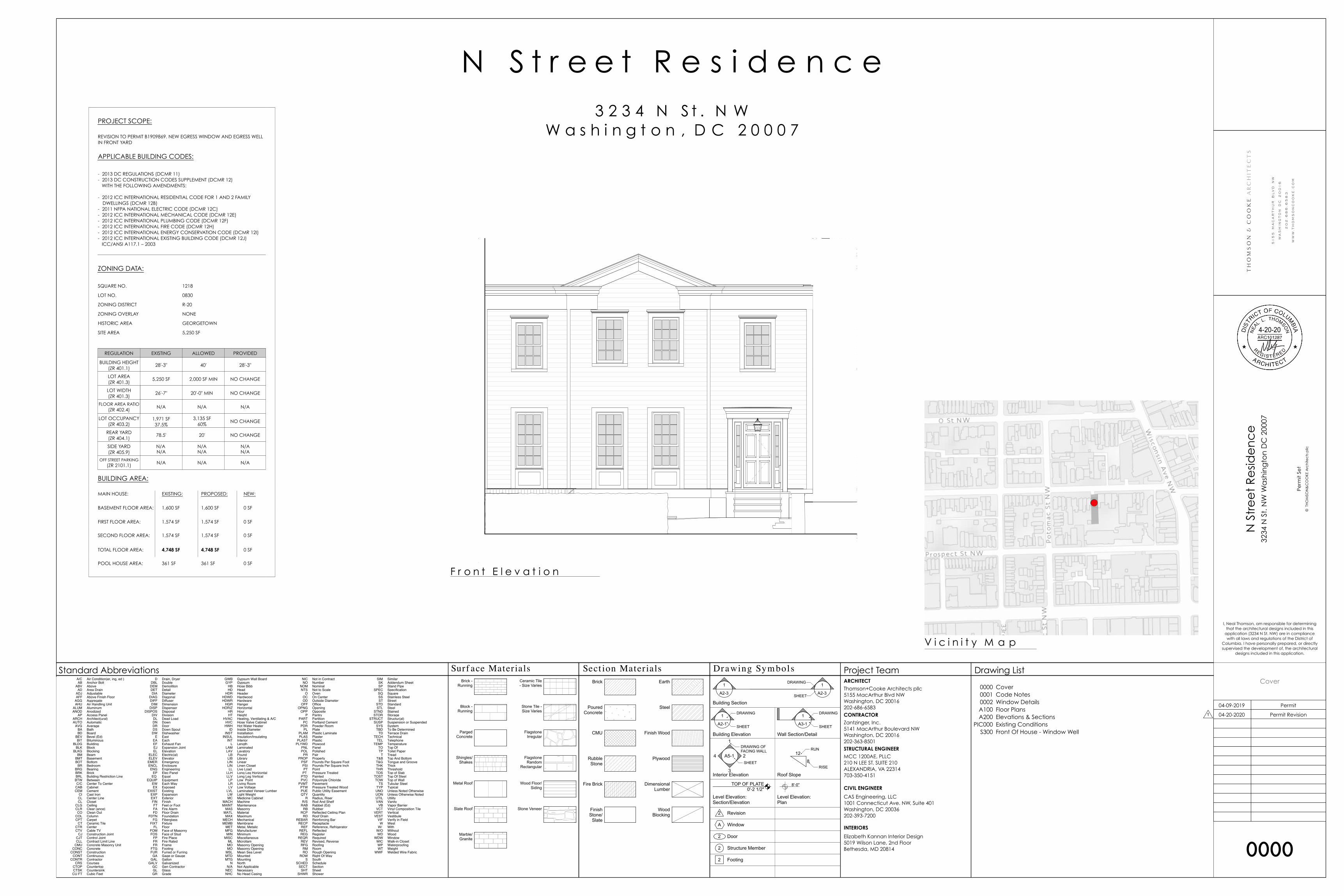
TABLE R402.1.1 INSULATION AND FENESTRATION REQUIREMENTS BY COMPONENTa
For SI: 1 foot = 304.8 mm. a. R-values are minimums. U-factors and SHGC are maximums. When insulation is installed in a cavity which is less than the label or design thickness of the
insulation, the installed R-value of the insulation shall not be less than the R-value specified in the table. b. The fenestration U-factor column excludes skylights. The SHGC column applies to all glazed fenestration. Exception: Skylights may be excluded from glazed
fenestration SHGC requirements in Climate Zones 1 through 3 where the SHGC for such skylights does not exceed 0.30. c. “15/19” means R-15 continuous insulation on the interior or exterior of the home or R-19 cavity insulation at the interior of the basement wall. “15/19” shall
be permitted to be met with R-13 cavity insulation on the interior of the basement wall plus R-5 continuous insulation on the interior or exterior of the home.“10/13” means R-10 continuous insulation on the interior or exterior of the home or R-13 cavity insulation at the interior of the basement wall.
d. R-5 shall be added to the required slab edge R-values for heated slabs. Insulation depth shall be the depth of the footing or 2 feet, whichever is less in ClimateZones 1 through 3 for heated slabs.
e. There are no SHGC requirements in the Marine Zone. f. Basement wall insulation is not required in warm-humid locations as defined by Figure R301.1 and Table R301.1. g. Or insulation sufficient to fill the framing cavity, R-19 minimum. h. First value is cavity insulation, second is continuous insulation or insulated siding, so “13+5” means R-13 cavity insulation plus R-5 continuous insulation or
insulated siding. If structural sheathing covers 40 percent or less of the exterior, continuous insulation R-value shall be permitted to be reduced by no morethan R-3 in the locations where structural sheathing is used – to maintain a consistent total sheathing thickness.
i. The second R-value applies when more than half the insulation is on the interior of the mass wall.
CLIMATE ZONE
FENESTRATION U-FACTORb
SKYLIGHTb U-FACTOR
GLAZED FENESTRATION
SHGCb, e
CEILING R-VALUE
WOOD FRAME WALL
R-VALUE
MASS WALL
R-VALUEi
FLOOR R-VALUE
BASEMENTc WALL
R-VALUE
SLABd R-VALUE & DEPTH
CRAWL SPACEc WALL
R-VALUE
1 NR 0.75 0.25 30 13 3/4 13 0 0 02 0.40 0.65 0.25 38 13 4/6 13 0 0 03 0.35 0.55 0.25 38 20 or 13+5h 8/13 19 5/13f 0 5/13
4 except Marine 0.35 0.55 0.40 49 20 or 13+5h 8/13 19 10 /13 10, 2 ft 10/13
5 and Marine 4 0.32 0.55 NR 49 20 or 13+5h 13/17 30g 15/19 10, 2 ft 15/19
6 0.32 0.55 NR 49 20+5 or 13+10h 15/20 30g 15/19 10, 4 ft 15/197 and 8 0.32 0.55 NR 49 20+5 or 13+10h 19/21 38g 15/19 10, 4 ft 15/19
RESIDENTIAL ENERGY EFFICIENCY
R-28 2013 DISTRICT OF COLUMBIA ENERGY CONSERVATION CODE
blown insulation. Computed R-values shall not include anR-value for other building materials or air films.
R402.1.3 U-factor alternative. An assembly with a U-factor equal to or less than that specified in TableR402.1.3 shall be permitted as an alternative to the R-value in Table R402.1.1.
R402.1.4 Total UA alternative. If the total building ther-mal envelope UA (sum of U-factor times assembly area) isless than or equal to the total UA resulting from using theU-factors in Table R402.1.3 (multiplied by the sameassembly area as in the proposed building), the buildingshall be considered in compliance with Table R402.1.1.The UA calculation shall be done using a method consis-tent with the ASHRAE Handbook of Fundamentals andshall include the thermal bridging effects of framing mate-rials. The SHGC requirements shall be met in addition toUA compliance.
R402.2 Specific insulation requirements (Prescriptive). Inaddition to the requirements of Section R402.1, insulationshall meet the specific requirements of Sections R402.2.1through R402.2.12.
R402.2.1 Ceilings with attic spaces. When SectionR402.1.1 would require R-38 in the ceiling, R-30 shall bedeemed to satisfy the requirement for R-38 wherever thefull height of uncompressed R-30 insulation extends overthe wall top plate at the eaves. Similarly, R-38 shall bedeemed to satisfy the requirement for R-49 wherever thefull height of uncompressed R-38 insulation extends overthe wall top plate at the eaves. This reduction shall notapply to the U-factor alternative approach in SectionR402.1.3 and the total UA alternative in Section R402.1.4.
R402.2.2 Ceilings without attic spaces. Where SectionR402.1.1 would require insulation levels above R-30 andthe design of the roof/ceiling assembly does not allow suf-ficient space for the required insulation, the minimumrequired insulation for such roof/ceiling assemblies shallbe R-30. This reduction of insulation from the require-ments of Section R402.1.1 shall be limited to 500 squarefeet (46 m2) or 20 percent of the total insulated ceilingarea, whichever is less. This reduction shall not apply to
the U-factor alternative approach in Section R402.1.3 andthe total UA alternative in Section R402.1.4.
R402.2.3 Eave baffle. For air permeable insulations invented attics, a baffle shall be installed adjacent to soffitand eave vents. Baffles shall maintain an opening equal orgreater than the size of the vent. The baffle shall extendover the top of the attic insulation. The baffle shall be per-mitted to be any solid material. R402.2.4 Access hatches and doors. Access doors fromconditioned spaces to unconditioned spaces (e.g., atticsand crawl spaces) shall be weatherstripped and insulatedto a level equivalent to the insulation on the surroundingsurfaces. Access shall be provided to all equipment thatprevents damaging or compressing the insulation. A woodframed or equivalent baffle or retainer is required to beprovided when loose fill insulation is installed, the pur-pose of which is to prevent the loose fill insulation fromspilling into the living space when the attic access isopened, and to provide a permanent means of maintainingthe installed R-value of the loose fill insulation.
R402.2.5 Mass walls. Mass walls for the purposes of thischapter shall be considered above-grade walls of concreteblock, concrete, insulated concrete form (ICF), masonrycavity, brick (other than brick veneer), earth (adobe, com-pressed earth block, rammed earth) and solid timber/logs.
R402.2.6 Steel-frame ceilings, walls, and floors. Steel-frame ceilings, walls, and floors shall meet the insulationrequirements of Table R402.2.6 or shall meet the U-factorrequirements of Table R402.1.3. The calculation of the U-factor for a steel-frame envelope assembly shall use aseries-parallel path calculation method.
R402.2.7 Floors. Floor insulation shall be installed tomaintain permanent contact with the underside of the sub-floor decking.
R402.2.8 Basement walls. Walls associated with condi-tioned basements shall be insulated from the top of thebasement wall down to 10 feet (3048 mm) below grade orto the basement floor, whichever is less. Walls associatedwith unconditioned basements shall meet this requirementunless the floor overhead is insulated in accordance withSections R402.1.1 and R402.2.7.
TABLE R402.1.3 EQUIVALENT U-FACTORSa
a. Nonfenestration U-factors shall be obtained from measurement, calculation or an approved source. b. When more than half the insulation is on the interior, the mass wall U-factors shall be a maximum of 0.17 in Climate Zone 1, 0.14 in Climate Zone 2, 0.12 in
Climate Zone 3, 0.087 in Climate Zone 4 except Marine, 0.065 in Climate Zone 5 and Marine 4, and 0.057 in Climate Zones 6 through 8.c. Basement wall U-factor of 0.360 in warm-humid locations as defined by Figure R301.1 and Table R301.1.
CLIMATE ZONE
FENESTRATION U-FACTOR
SKYLIGHT U-FACTOR
CEILING U-FACTOR
FRAME WALL
U-FACTOR
MASS WALL U-FACTORb
FLOOR U-FACTOR
BASEMENT WALL
U-FACTOR
CRAWL SPACE WALL
U-FACTOR
1 0.50 0.75 0.035 0.082 0.197 0.064 0.360 0.4772 0.40 0.65 0.030 0.082 0.165 0.064 0.360 0.4773 0.35 0.55 0.030 0.057 0.098 0.047 0.091c 0.136
4 except Marine 0.35 0.55 0.026 0.057 0.098 0.047 0.059 0.0655 and Marine 4 0.32 0.55 0.026 0.057 0.082 0.033 0.050 0.055
6 0.32 0.55 0.026 0.048 0.060 0.033 0.050 0.0557 and 8 0.32 0.55 0.026 0.048 0.057 0.028 0.050 0.055
RESIDENTIAL ENERGY EFFICIENCY
R-30 2013 DISTRICT OF COLUMBIA ENERGY CONSERVATION CODE
area is exempted from the U-factor requirement in SectionR402.1.1. This exemption shall not apply to the U-factoralternative approach in Section R402.1.3 and the total UAalternative in Section R402.1.4.
R402.3.5 Sunroom U-factor. All sunrooms enclosingconditioned space shall meet the fenestration requirementsof this code.
Exception: For sunrooms with thermal isolation andenclosing conditioned space, in Climate Zones 4
through 8, the following exceptions to the fenestrationrequirements of this code shall apply:
1. The maximum fenestration U-factor shall be0.45; and
2. The maximum skylight U-factor shall be 0.70.New fenestration separating the sunroom withthermal isolation from conditioned space shallmeet the building thermal envelope requirementsof this code.
TABLE R402.4.1.1 AIR BARRIER AND INSULATION INSTALLATION
a. In addition, inspection of log walls shall be in accordance with the provisions of ICC-400.
COMPONENT AIR BARRIER CRITERIAa INSULATION INSTALLATIONCRITERIA
General Requirements
A continuous air barrier shall be installed in the buildingenvelope. Exterior thermal envelope shall contain acontinuous air barrier. Breaks or joints in the air barriershall be sealed.
Air-permeable insulation shall not be used as a sealing material.
Ceiling / attic
The air barrier in any dropped ceiling/soffit shall bealigned with the insulation and any gaps in the air barriersealed. Access openings, drop down stair or knee walldoors to unconditioned attic spaces shall be sealed.
The insulation in any dropped ceiling/soffit shall be aligned withthe air barrier.
Walls Junctions of the foundation and sill plate shall be sealed.Junctions of the top plate and top of exterior walls shallbe sealed. Knee walls shall be sealed.
Corners and headers shall be insulated. Exterior thermal envelopeinsulation for framed walls shall be installed in substantialcontact and continuous alignment with the air barrier.
Windows, skylights and doors The space between window/door jambs and framing, andskylights and framing shall be sealed.
Rim joists Rim joists shall include the air barrier. Rim joists shall be insulated.
Floors (including above garageand cantilevered floors)
The air barrier shall be installed at any exposed edge ofinsulation.
Insulation shall be installed to maintain permanent contact withunderside of subfloor decking.
Crawl space walls Exposed earth in unvented crawl spaces shall be coveredwith a Class I vapor retarder with overlapping jointstaped.
Where provided in lieu of floor insulation, insulation shall bepermanently attached to the crawlspace walls.
Shafts, penetrations Duct shafts, utility penetrations, and flue shafts openingto exterior or unconditioned space shall be sealed.
Narrow cavities Batts in narrow cavities shall be cut to fit, or narrow cavities shallbe filled by insulation that on installation readily conforms to theavailable cavity space.
Garage separation Air sealing shall be provided between the garage andconditioned spaces.
Recessed lighting Recessed light fixtures installed in the building thermalenvelope shall be sealed to the drywall.
Recessed light fixtures installed in the building thermal envelopeshall be air tight and IC rated.
Plumbing and wiring
Batt insulation shall be cut neatly to fit around wiring andplumbing in exterior walls, or insulation that on installationreadily conforms to available space shall extend behind pipingand wiring.
Shower / tub on exterior wall The air barrier installed at exterior walls adjacent toshowers and tubs shall separate them from the showersand tubs.
Exterior walls adjacent to showers and tubs shall be insulated.
Electrical / phone box on exteriorwalls
The air barrier shall be installed behind electrical orcommunication boxes, or air sealed boxes shall beinstalled.
HVAC register boots HVAC register boots that penetrate building thermalenvelope shall be sealed to the subfloor or drywall.
Fireplace An air barrier shall be installed on fireplace walls.Fireplaces shall have gasketed doors.
N/A N/A
N/A N/A
N/A
N/A N/A
N/A N/A
N/A N/A
N/A N/A
N/A N/A
YES 0001
N/A N/A
N/A N/A
N/A N/A
N/A N/A
YES 0001
YES N/A
N/A N/A
N/A N/A
N/A
N/A N/A
N/A N/A
YES N/A
N/A N/A
N/A
N/A N/A
N/A N/A
N/A N/A
N/A
N/A
N/A
X
N/A
N/A
N/A
N/AN/A
N/AN/A
N/AN/A
N/AN/A
N/AN/A
YES N/A
N/A N/A
N/A N/A
N/A N/A
N/A N/A
N/A N/A
N/A N/A
N/A
BSMTFLR
A200
N/A N/A
N/A N/A
N/A
N/A
N/A N/A
N/A
0.35 0001
0.35 0001
0.4 0001
YES 0001
N/A N/A
N/A N/A
N/A
YES N/A
N/A N/A
N/AN/A
R-13 A200
Window Schedule
ID
W001
Qty
1
Units
1
Type
Casement
Manuf. Model/Size
2-6x4-0
Lites
3W4H
Hinge
L
Ext Casing
Bkmld
Transom
Height LitesLocation Note
Egress
1
T a b l e 1: R - V a l u e
T a b l e 2 : U - V a l u e
T a b l e 3 : A i r S e a l i n g N o t e s
2012
10" min.7 3/4" max.
Permit Revision04-20-2020
Permit04-09-2019
Perm
it Se
t

NO
T FO
R C
ON
STR
UC
TIO
N
N S
tre
et
Re
side
nc
e32
34 N
St.
NW
Wa
shin
gto
n D
C 2
0007
© T
HO
MSO
N&
CO
OKE
Arc
hite
cts
pllc
CD Release #101-15-2019
CD Revision 103-19-2019
CD Release #207-07-2019
CD Release #307-23-2019
80% CD Release09-06-2019
90% CD Release10-04-2019
95% CD Release10-30-2019
96% CD Release12-20-2019
Electrical Release02-10-2020
97% CD Release02-11-2020
98% CD Release03-02-2020
99% DRAFT03-12-2020
I, Neal Thomson, am responsible for determiningthat the architectural designs included in this
application (3234 N St. NW) are in compliancewith all laws and regulations of the District of
Columbia. I have personally prepared, or directlysupervised the development of, the architectural
designs included in this application.
0002
Window Details
4-20-20
B16 | Technical Guide Technical Guide | B17Casement WindowsCasement Windows
Note: • Other jamb widths available.• All dimensions to have +/- 1/16” (2mm) tolerance.
Casement Window Detail
Head & SillDetail
Head & SillDetail
Plan View
Note: • Other jamb widths available.• All dimensions to have +/- 1/16” (2mm) tolerance.
Push Out Casement Window Detail
METAL CLAD
WOOD EXTERIOR
DOUBLETRIPLE
DOUBLETRIPLE
HINGED WOODSCREEN
RETRACTABLESCREEN
RETRACTABLESCREEN
HINGED WOODSCREENMETAL CLAD DOUBLE
4 9/16" (116 mm)ADAMS CASING WITH BC SILL NOSE
RETRACTABLE SCREEN
METAL CLAD TRIPLE6 9/16" (166 mm)
PUTTY GLAZING STOPSHINGED WOOD SCREEN
WOOD EXTERIOR DOUBLE4 9/16" (116 mm)
2" BRICKMOULD WITH STANDARD SILL NOSINGHINGED WOOD SCREEN
WOOD EXTERIOR TRIPLE6 9/16" (166 mm)
ADAMS CASING WITH BC SUBSILLSQUARE GLAZING STOPSRETRACTABLE SCREEN
2 1/
16"
[52]
3 3/
16"
[82]
3" [76]
4 9/16"
[116]
FRA
ME
HEI
GH
T
1 1/
16"
[27]
1 5/
16"
[34]
1 3/
8"[3
5]
2 1/
16"
[52]
3 3/
16"
[82]
3"[7
6]
FRA
ME
HEI
GH
T
1 1/
16"
[27]
2 1/
2"
[64]
6 9/16"[166]
2 1/
16"
[52]
3 3/
16"
[82]
3"[7
6]
1 3/4"
[44]
4 9/16"
[116]
3"[7
6]
FRA
ME
HEI
GH
T2
1/16
"[5
2]
3 3/
16"
[82]
3" [76]
1 3/16"[31]
1 1/
4"
[32]
1 3/
8"[3
5]
FRA
ME
HEI
GH
T
5/8"
[16]
5/8"
[16]
6 9/16"[166]
2 1/
8"[5
4]
1 3/
8"[3
5] 2 1/
8"[5
4]
2 1/
4"[5
7]
1 3/
8"[3
5]
1 15/16"[50]
2 1/4"[57]
1 11/16"[43]
2 1/
4"[5
7]
1 7/16"[37]
1 3/
8"[3
5]5/8"
[16]
5/8"
[16]
2 1/
4"[5
7]
1 3/
8"[3
5]
1 15/16"[50]
1 13/16"
[45]
2 1/
4"
[57]
1 3/
8"
[35]
3 1/
16"
[78]
1 3/
8"
[35]
1 11
/16"
[43]
VISI
BLE
GLA
SS
1 11/16"
[43]
3"
[76]
3"
[76]
6"
[153]
1 1/4"
[32]2 3/4"
[70]15/16"
[24]
5/16"
[8]
3"
[76]3"
[76]
6"[153]
1 1/4"
[32]2 3/4"
[70]15/16"
[24]
5/16"
[8]
1 1/
16"
[27]
1 1/
2"[3
9]
1 1/
4"
[32]
Head & SillDetail
Head & SillDetail
Plan View
Technical Guide | B1Casement WindowsBCasement Windows
Technical Guide B
B2 | Technical Guide Technical Guide | B3Casement WindowsCasement Windows
Styles
Traditional, Push Out and Mission® options.
Standard Features
• Natural, clear Douglas Fir interior (no visible finger
joints)
• 4 9/16” (116 mm) jamb construction
• LowE insulated glazing with 1/2” (13 mm) airspace
• Roto gear operator and concealed sash locks
• Extruded aluminum cladding in a variety of standard
colors, primed wood or clear fir exterior
• Flexible continuous weatherstrip system
• Insect screens
• Metal handle, cover and locks
Hardware
Multiple hardware type and finish choices are available.
See the Hardware in section A for more information
Glazing
LowE Double, LowE Triple, Tranquility® and StormForce™.
StormForce is not available on all products.
Simulated Divided Lites (SDL)
Ogee Profile — 3/4” (19 mm), 1 1/8” (30 mm), 2” (51 mm)
Putty Profile — 5/8” (16 mm), 7/8” (22 mm), 1 1/8” (30 mm),
2” (51 mm)
Square Profile (interior only) — 3/4” (19 mm), 7/8” (22 mm),
1 1/8” (30 mm), 2” (51 mm)
Casing
Wood: 2” (51 mm) Brickmould, 3 1/2” (89 mm) Flat,
5 1/2” (139 mm) Flat, Adams and Williamsburg.
Metal Clad: 2” (51 mm) Brickmould, 3 1/2” (89 mm) Flat,
2” clad frame extension, Nose & Cove, Adams, Williamsburg
and Kerf.
Metal Clad Color Spectrum
All Palette colors, including anodized finishes. Available in
Cyprium Collection.
Push Out CasementCasement Mission® Casement
Product Features Specifications
Traditional Casement
Mission® Casement
French Casement
Push Out Casement
VARIABLES
Function
Use for Egress
Available with Screen
Concealed Hardware
Durability
Low Maintenance
Metal Clad Exterior
Clear Douglas Fir
Exterior Finish
Clear Mahogany
Exterior Finish
Primed Exterior Finish
Cyprium Collection
Performance
LowE Double
LowE Triple
StormForce™
Appearance
SDL
Traditional Casement
Mission® Casement
French Casement
Push Out Casement
HARDWARE STYLES
Folding Crank Handle
Push Out Handle
Multipoint Lock
Standard Optional
Finish Options: Refer to Section A.
Visit the Loewen Photo Gallery online at www.loewen.com for a large collection of Loewen product and elevation photography.Numerous custom window configuration opportunities exist — please contact your Authorized Loewen Dealer. Specifications and technical information are subject to change without notice. Imperial and metric measurements are converted accurately. However, in some cases, industry standards cause a 1 mm variance. (Example: 3/4" is shown as 19 mm for all glass measurements.) Cad Download: www.loewen.com/architect | Installation Instructions: www.loewen.com
Standards
Most units have been tested by an independent laboratory
for air and water infiltration, structural performance, and
thermal performance requirements.
Frame & Sash
Manufactured from Coastal Douglas Fir kiln-dried lumber
with frame construction designed for 4 9/16” (116 mm)
jamb. All wood exterior components are factory primed
unless specified as clear exterior. Minor scratches
or abrasions in the wood surface or primer are not
considered defects.
Alternate Species
The entire Loewen product line is also available in optional
Mahogany.
Preservative Treated
All wood parts are dipped in approved preservative.
Glazing
With countless glazing configurations and LowE coating
options, we ensure that you can choose the perfect blend of
protection and comfort.
Insulating Glass
Double or triple glass configurations with 1/2” (13 mm)
airspace.
LowE Systems
LowE best describes the benefits of the product that
incorporates glazing coatings and Argon gas. LowE systems
help reduce heating and cooling costs, providing superior
energy efficiency.
Simulated Divided Lites (SDL)
Standard SDL complete with airspace grilles, where
available. Grille bars are permanently applied to the interior
and exterior.
Hardware Option
Operator and sash locks are available in a variety of
finishes. See section A.
Metal Cladding
Heavy duty exterior metal cladding comprised of extruded
aluminum is available in a variety of Palette colors, including
anodized and Cyprium (copper and bronze cladding).
Interior of window can be natural wood (unfinished) or
primed. Metal clad units are supplied ready-to-install
complete with integral metal nailing flange.
Hardware
Standard Casement sash opens out to nearly 90 degrees
for ease of cleaning. The roto gear operator will hold the
sash at any position in its operating radius. The sash
is supported by concealed heavy-duty hinges. All steel
components are coated for superior corrosion protection.
Double Weatherstrip
The combination of a continuous, flexible foam weatherstrip
and a flexible automotive type bulb weatherstrip ensures
maximum energy efficiency and protection against air and
water infiltration.
Screen
Screens available in bronze, linen, Tuscany brown, brushed
aluminum or black aluminum frame, screened with anti-
glare fiberglass cloth. Wood-framed screens and High
Transparency mesh available. Optional Retractable Screen
and Swinging Screen available. Swinging Screen available
on Push Out models only.
Egress
Consult local building codes for confirmation of size
requirements for your area. Special egress hardware is
available for Casement windows, which enables some sizes
to meet egress codes, eliminating the need to go to the next
larger size window. Consult your Authorized Loewen Dealer
for more details.
1
L o e w e n W i n d o w s T e c h n i c a l I n f o r m a t i o n
Permit Revision04-20-2020
Permit04-09-2019
Perm
it Se
t
NO
T FO
R C
ON
STR
UC
TIO
N
N S
tre
et
Re
side
nc
e32
34 N
St.
NW
Wa
shin
gto
n D
C 2
0007
© T
HO
MSO
N&
CO
OKE
Arc
hite
cts
pllc
CD Release #101-15-2019
CD Revision 103-19-2019
CD Release #207-07-2019
CD Release #307-23-2019
80% CD Release09-06-2019
90% CD Release10-04-2019
95% CD Release10-30-2019
96% CD Release12-20-2019
Electrical Release02-10-2020
97% CD Release02-11-2020
98% CD Release03-02-2020
99% DRAFT03-12-2020
I, Neal Thomson, am responsible for determiningthat the architectural designs included in this
application (3234 N St. NW) are in compliancewith all laws and regulations of the District of
Columbia. I have personally prepared, or directlysupervised the development of, the architectural
designs included in this application.
A100
Floor Plans
4-20-20
SD
GENERAL NOTES:
1. UNLESS INDICATED OTHERWISE, DIMENSIONS ARE TO FACE OFFRAMING.
2. VERIFY ALL EXTERIOR RISER AND TREAD DIMENSIONS IN THEFIELD.
3. ALL SMOKE/CARBON MONOXIDE DETECTORS TO BE HARD-WIRED TO DEDICATED CIRCUIT, INTERCONNECTED & PROVIDEDWITH BATTERY BACKUP
4. PROVIDE CARBON MONOXIDE ALARMS PER R315.15. ALL STAIRS HANDRAILS AND GUARDS SHALL BE CONSTRUCTED IN
ACCORDANCE WITH SECTION R311 AND R312 OF THE 2012 IRC.6. SEE FRAMING PLANS FOR COORDINATION OF POST
REQUIREMENTS.7. ALL INTERIOR PARTITIONS NOT DIMENSIONED SHALL BE 3 1/2"8. ALL ANGLES ARE 90 AND OR 45 UNLESS NOTED OTHERWISE.9. REFER TO EXTERIOR ELEVATIONS & DOOR/ WINDOW SCHEDULE
FOR WINDOW HEAD HEIGHTS.10. ALL DOOR DIMENSIONS GIVEN IN FEET AND INCHES.
WALL TYPES
TYPICAL EXTERIOR WALL: 2"X6" WOOD STUDS 16" O.C. WITH R- 21OPEN CELL SPRAY FOAM INSULATION, 1/2" OSB SHEATHING,TYVEK BUILDING WRAP, AND SIDING; SEE ELEVATIONS. INTERIORFINISH TO BE 1/2" GYP. BOARD.
TYPICAL INTERIOR WALL: 2"X4" STUDS 16" O.C. WITH 1/2" GYPBOARD EACH SIDE.
N S
tre
et
Re
side
nc
e32
34 N
St.
NW
Wa
shin
gto
n D
C 2
0007
© T
HO
MS
ON
&C
OO
KE
Arc
hite
cts
pllc
OG
B C
on
ce
pt
Re
vie
w
OGB ConceptReview
3/12/19
Revision 13/19/19
A101
Floor Plans
B
W103 W102
W101
101
6'-8"2'-4"
D101
A
DRIVE COURT
DN
DN
DN
2'-0
"3" 3"
3'-0
1/2
"
3'-1
"2'
-8"
6'-11 1/2"
5'-10" 3'-9"
4'-1
"8"
3"2'
-1"
6"
6" 5'-5" 6"10 RISERS @ 7 3/4"9 TREADS @ 10"
NEW AREAWAY
4 R
ISER
S @
7 3
/4"
3 TR
EAD
S @
11"
WOOD GATE FOR TRASH REMOVAL
NEW METAL HANDRAIL @ 36"A.F.F. AND BALUSTERS @ 4" O.C.
NEW METAL HANDRAIL @ 36"A.F.F. AND BALUSTERS @ 4" O.C.
NEW CONCRETE STOOP ANDSTEPS WITH STONE TREADS
NEW WINDOW
HIDDEN DRAWER UNDER WINDOWS, TYP.
NEW WINDOWS TO MATCH EXISTING
3'-0" x 6'-2"
CLO
SET
EXISTINGSIDEWALK
EXISTINGSIDEWALK
RECYCLE
DUSTBIN
EXISTINGDRIVEWAY
EXISTING EXTERIORWALLS TO REMAIN
PLANTING
PLANTING
PLA
NTI
NG
PLANTING
EXISTING RETAININGWALL TO REMAIN
1A201
2A201
2A201
DEMOLISH EXISTING CMU WINDOW WELLS (CIRCA 1960)
DEMOLISH EXISTING STOOP AND STEPSDEMOLISH EXISTING AREAWAY
DEMOLISH EXISTINGDOOR
DEMOLISH EXISTINGWINDOW
DEMOLISH EXISTINGWINDOW
DEMOLISH EXISTING DOOR
DEMOLISH EXISTING CMU WALL (CIRCA 1960)
EXISTING RETAINING WALL TO REMAIN
DEMOLISH EXISTING STOOP AND STEPS
EXISTING EXTERIORWALLS TO REMAIN
012
6'-8"4'-0"
D001
0132'-4"EXERCISE
DNDN
ENTRY
UP
3 1/
2"6"
2'-6
1/2
"3
1/2"
4'-2
1/2
"3
1/2"
3 1/
2"6"
8"
3'-0
1/2
"
3'-3"
3'-0
1/2
"4'
-1"
8"
8" 5'-10" 3'-9"
2'-4
"8"
2'-9
"
8" 5'-5" 8" 1'-9 1/2"
8" 3'-2" 8"
UNDERPIN WALLSPER STRUCTURAL
CMU WALL PER STRUCTURAL
10 RISERS @ 7 3/4"9 TREADS @ 10"
NEW AREAWAY
NEW STEPS ANDSTOOP ABOVE
NEW METAL HANDRAIL @ 36"A.F.F. AND BALUSTERS @ 4" O.C.
NEW DOOR
2X6 STUD WALL
INFILL WINDOWS AS REQUIRED
2'-6" x 6'-8"
2X FURRINGTURNED STUDS
CLO
SET
SHLVG
4"
EXISTING EXTERIORWALLS TO REMAIN
2A201
2A201
0 1 2 4 8 16
DEMOLISH EXISTING STOOP AND STEPSDEMOLISH EXISTING AREAWAY
DEMOLISH PORTIONOF EXISTING WALL
AND DOOR
DEMOLISH EXISTINGWINDOWS
DEMOLISH EXISTINGWINDOWS
EXISTING EXTERIORWALLS TO REMAIN
DEMOLISH EXISTING CMU WINDOW WELLS (CIRCA 1960)
W208
W206W207
W205
206
6'-8"2'-4"
205
6'-8"4'-0" BATH 2
TILE
4'-1
1 1/
2"4"
3 1/
2"
2'-8
1/2
"3
1/2"
5
6
7
8 A505
9
10
11
12 A505
NEW WINDOWS TOMATCH EXISTING, TYP.
STANDING SEAMCOPPER ROOF
CLO
SET
EXISTING EXTERIORWALLS TO REMAIN
2A201
2A201
DEMOLISH EXISTINGWINDOW
DEMOLISH EXISTINGWINDOW
DEMOLISH EXISTINGWINDOW
DEMOLISH EXISTINGWINDOW
EXISTING EXTERIORWALLS TO REMAIN
F i r s t F l o o r P l a n1/8" = 1'-0"5F i r s t F l o o r D e m o l i t i o n P l a n
1/8" = 1'-0"2
B a s e m e n t P l a n1/8" = 1'-0"4B a s e m e n t D e m o l i t i o n P l a n
1/8" = 1'-0"1
S e c o n d F l o o r P l a n1/8" = 1'-0"6S e c o n d F l o o r D e m o l i t i o n P l a n
1/8" = 1'-0"3
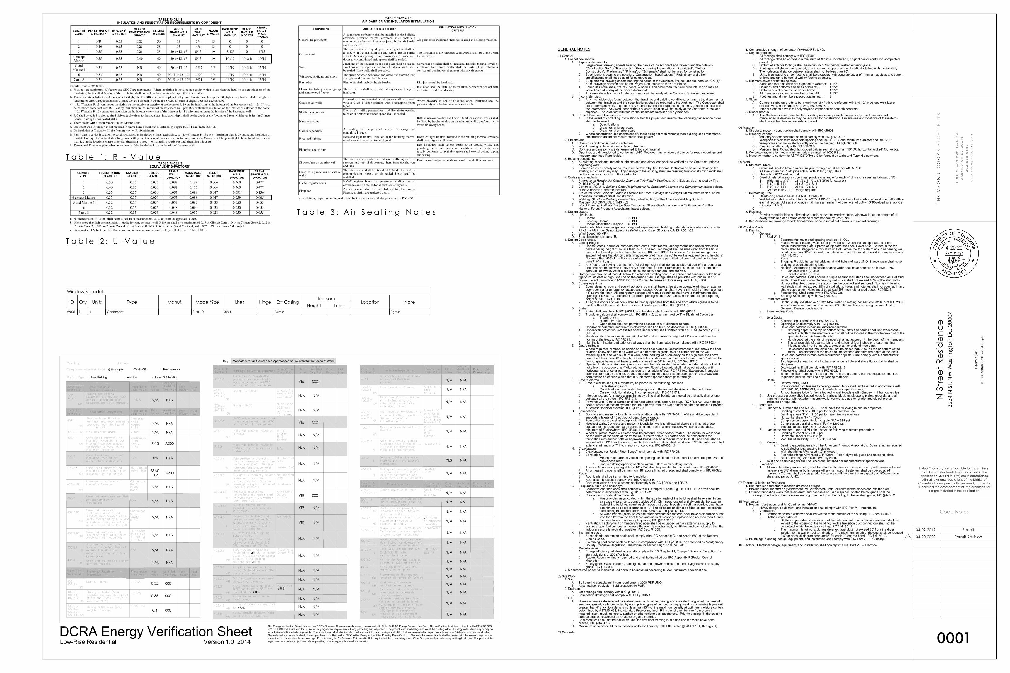
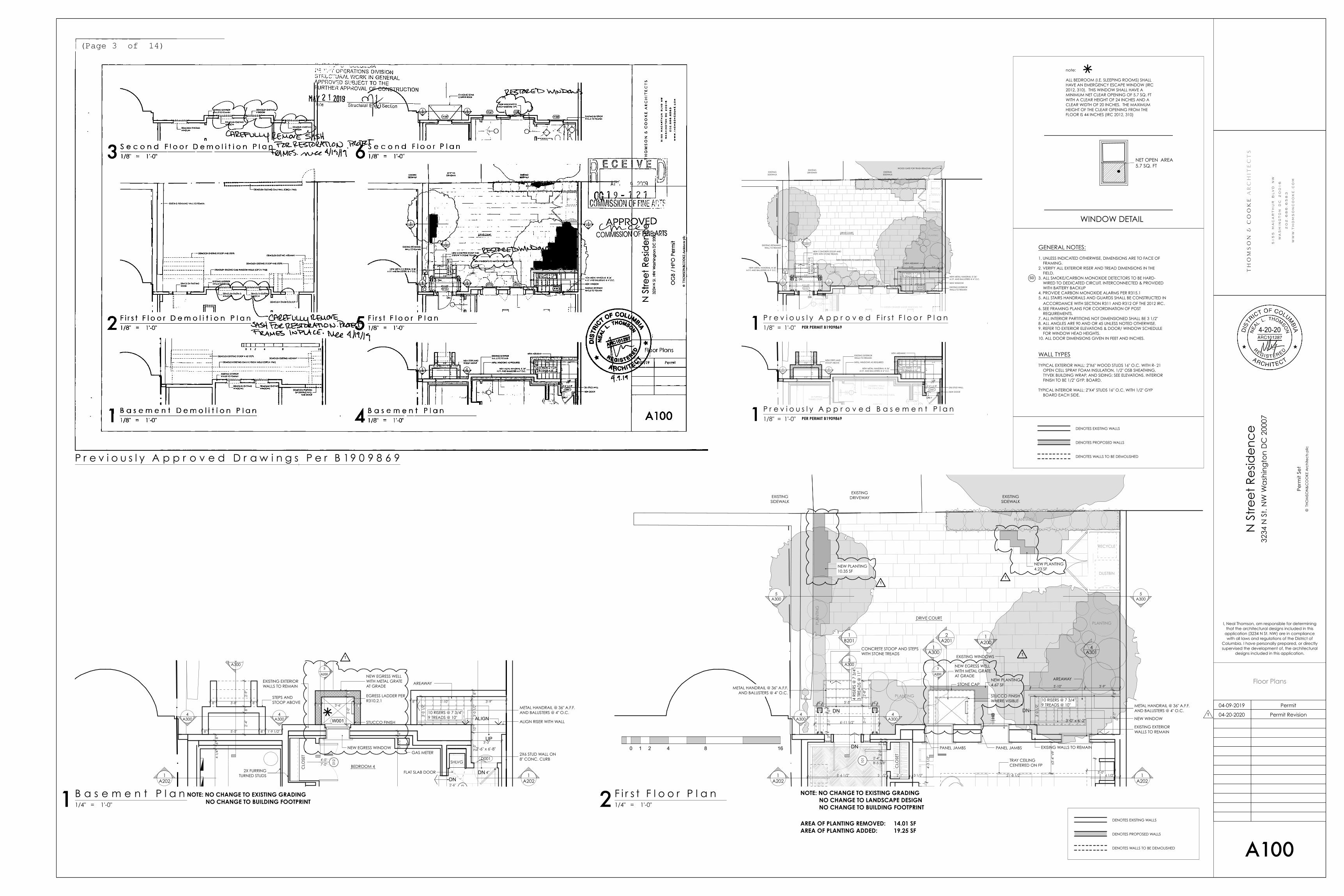
(Page 3 of 14)
B
101
8'-5 5/8"2'-4"
A
DRIVE COURT
DN
DN
DN
HB
3
A200
0 1 2 4 8 16
3A300
2'-0
"3" 3"
8'-6 1/2" 3 1/2" 2'-1" 3 1/2" 21'-8 1/2" 6 1/2"
3'-0
1/2
"
3'-1
"2'
-8"
6'-11 1/2"
5'-10" 3'-9"
4'-1
"8"
3"2'
-1"
6"
6" 5'-5" 6"
±3'-4
" VIF
3'-0"
4'-3
1/2
"
10 RISERS @ 7 3/4"9 TREADS @ 10"
AREAWAY
4 R
ISER
S @
7 3
/4"
3 TR
EAD
S @
11"
METAL HANDRAIL @ 36" A.F.F.AND BALUSTERS @ 4" O.C.
METAL HANDRAIL @ 36" A.F.F.AND BALUSTERS @ 4" O.C.
CONCRETE STOOP AND STEPSWITH STONE TREADS
NEW WINDOW
TRAY CEILINGCENTERED ON FP
PANEL JAMBS PANEL JAMBS
NEW EGRESS WELLWITH METAL GRATEAT GRADE
EXISING WALLS TO REMAIN
STONE CAP
STUCCO FINISHWHERE VISIBLE
NEW PLANTING10.35 SF
NEW PLANTING4.23 SF
NEW PLANTING4.67 SF
EXISTING WINDOWS
3'-0" x 6'-2"
CLO
SET
EXISTINGSIDEWALK
EXISTINGSIDEWALK
RECYCLE
DUSTBIN
EXISTINGDRIVEWAY
1A200
1A202
1A202
EXISTING EXTERIORWALLS TO REMAIN
PLANTING
PLANTING
PLA
NTI
NG
PLANTING
1A300
1B201
2A201
4A300
4A300
5A300
5A300
4A301
012
7'-0"4'-0"
W001
D001
0132'-6"
DNDN
UP
BEDROOM 4
3
A200
3A300
3 1/
2"6"
4 1/
4"6"
8"
3'-0
1/2
"
3'-3"
3'-3
"10
"3'
-0 1
/2"
8"
8" 5'-10" 3'-9"
2'-4
"8"
2'-9
"
8" 5'-5" 8" 1'-9 1/2"
8" 3'-8" 8"8" 3'-6" 8"
3'-0
"8"
10 RISERS @ 7 3/4"9 TREADS @ 10"
AREAWAY
STEPS ANDSTOOP ABOVE
METAL HANDRAIL @ 36" A.F.F.AND BALUSTERS @ 4" O.C.
2X6 STUD WALL ON8" CONC. CURB
FLAT SLAB DOOR
GAS METER
ALIGN RISER WITH WALL
WHOLE HOUSE WATERFILTRATION SYSTEM
NEW EGRESS WELLWITH METAL GRATEAT GRADE
NEW EGRESS WINDOW
EGRESS LADDER PERR310.2.1
STUCCO FINISH
2'-6" x 6'-8"
2X FURRINGTURNED STUDS
CLO
SET
SHLVG
4"
EXISTING EXTERIORWALLS TO REMAIN
1A202
1A202
ALIGN4
A3004
A300
NET OPEN AREA5.7 SQ. FT
note:
ALL BEDROOM (I.E. SLEEPING ROOMS) SHALLHAVE AN EMERGENCY ESCAPE WINDOW (IRC2012, 310). THIS WINDOW SHALL HAVE AMINIMUM NET CLEAR OPENING OF 5.7 SQ. FTWITH A CLEAR HEIGHT OF 24 INCHES AND ACLEAR WIDTH OF 20 INCHES. THE MAXIMUMHEIGHT OF THE CLEAR OPENING FROM THEFLOOR IS 44 INCHES (IRC 2012, 310)
WINDOW DETAIL
1
11
11
P r e v i o u s l y A p p r o v e d F i r s t F l o o r P l a n1/8" = 1'-0"1
P r e v i o u s l y A p p r o v e d B a s e m e n t P l a n1/8" = 1'-0"1
P r e v i o u s l y A p p r o v e d D r a w i n g s P e r B 19 0 9 8 6 9
F i r s t F l o o r P l a n1/4" = 1'-0"2B a s e m e n t P l a n
1/4" = 1'-0"1
DENOTES EXISTING WALLS
DENOTES PROPOSED WALLS
DENOTES WALLS TO BE DEMOLISHED
PER PERMIT B1909869
PER PERMIT B1909869
NOTE: NO CHANGE TO EXISTING GRADING NO CHANGE TO LANDSCAPE DESIGN NO CHANGE TO BUILDING FOOTPRINT
NOTE: NO CHANGE TO EXISTING GRADING NO CHANGE TO BUILDING FOOTPRINT
DENOTES EXISTING WALLS
DENOTES PROPOSED WALLS
DENOTES WALLS TO BE DEMOLISHED
Permit Revision04-20-2020
Permit04-09-2019
Perm
it Se
t
AREA OF PLANTING REMOVED: 14.01 SFAREA OF PLANTING ADDED: 19.25 SF

NO
T FO
R C
ON
STR
UC
TIO
N
N S
tre
et
Re
side
nc
e32
34 N
St.
NW
Wa
shin
gto
n D
C 2
0007
© T
HO
MSO
N&
CO
OKE
Arc
hite
cts
pllc
CD Release #101-15-2019
CD Revision 103-19-2019
CD Release #207-07-2019
CD Release #307-23-2019
80% CD Release09-06-2019
90% CD Release10-04-2019
95% CD Release10-30-2019
96% CD Release12-20-2019
Electrical Release02-10-2020
97% CD Release02-11-2020
98% CD Release03-02-2020
99% DRAFT03-12-2020
I, Neal Thomson, am responsible for determiningthat the architectural designs included in this
application (3234 N St. NW) are in compliancewith all laws and regulations of the District of
Columbia. I have personally prepared, or directlysupervised the development of, the architectural
designs included in this application.
A200
Elevations & Sections
4-20-20
0 1 2 4 8 16
0"1st Floor
10'-9 3/4"2nd Floor
20'-9 3/4"Attic
8" 3'-6" 8"
STANDING SEAMCOPPER ROOF
METAL HANDRAIL @36" A.F.F. ANDBALUSTERS @ 4"O.C.
REPAIR OR REPLACE PTDWOOD TRIM AS REQUIRED
EXISTING RETAININGWALL TO REMAINMETAL HANDRAIL @ 36" A.F.F.
AND BALUSTERS @ 4" O.C.
RESTORE ALLWINDOWS IN KIND,By "The Craftsmen
Group"
REPAIR OR REPLACE EXISTINGSIDING IN KIND AS REQUIRED
EXISTING CHIMNEY TO REMAIN
NEW WINDOW TO MATCHEXISTING (THIS LOCATION), By
"The Craftsmen Group"
EXISTING ROOF TO REMAIN
EXISTING ROOF TO REMAIN
WOOD PANEL TOMATCH EXISTING
REPAIR OR REPLACE EXISTINGCORNER BOARDS IN KIND ASREQUIRED
MATCH EXISTING HEAD HEIGHT
NEW PTD WOOD TRIMTO MATCH EXISTING
PTD WOOD TRIM TOMATCH EXISTING
PTD WOOD WRAPPED 6" COLUMNS
PTD WOOD TRIM
STUCCO BASE TOMATCH EXISTING
LANTERN - SEE SPECS
NEW DOOR IN EXISTING OPENING
NEW EGRESS WELL
LOEWEN EGRESS WINDOW(BEYOND) SEE SHEET 0002
7'-0" A.F.F.HEAD HGT
W001
EXISTING PARTY WALL
FOOTERS PER STRUCTURAL
RETAINING WALLS PER STRUCTURAL
0"1st Floor
103.50'2nd Floor
3
A200
85.33Egress Well
92.691st Floor
4'-5
"
3'-3
3/8
"
8" 3'-0"
PTD METALEGRESS LADDER
PER R310.2.1
CMU RETAINING WALL
STUCCO
STONE CAP
METAL EGRESS GATE
STUCCO ABOVEGRADE
FOOTER PERSTRUCTURAL
EXISTING SLABTO REMAIN
EXIST FLOORFRAMING TO
REMAIN
82.58Basement
EXISTING FOUNDATIONWALLS TO REMAIN
EXISTING EXTERIORWALLS TO REMAIN
NEW EGRESS WINDOWIN EXISTING WALL
R-13 SPRAY FOAMINSULATION
R-13 SPRAY FOAMINSULATION
(Page 4 of 14)
85.33Egress Well
92.691st Floor
PTD METALEGRESS LADDER
PER R310.2.1
CMU RETAINING WALL
STUCCO
STONE CAP
METAL EGRESS GATE
STUCCO ABOVEGRADE
FOOTER PERSTRUCTURAL
DRAINAGE MAT, DAMPPROOFING, AND DRAIN
TILE WITH GRAVEL BACKFILL
NEW EGRESS WINDOWIN EXISTING WALL
1
1
1
1
P r o p o s e d F r o n t E l e v a t i o n1/4" = 1'-0"1
F r o n t E l e v a t i o n ( S t r e e t )1/4" = 1'-0"2W i n d o w W e l l D e t a i l
1/2" = 1'-0"3
P r e v i o u s l y A p p r o v e d D r a w i n g s P e r B 19 0 9 8 6 9
W i n d o w E l e v a t i o n1/2" = 1'-0"4
NOTE: NO CHANGEVISIBLE FROM STREET
NOTE: NO CHANGEABOVE GRADE
Permit Revision04-20-2020
Permit04-09-2019
Perm
it Se
t

NO
T FO
R C
ON
STR
UC
TIO
N
N S
tre
et
Re
side
nc
e32
34 N
St.
NW
Wa
shin
gto
n D
C 2
0007
© T
HO
MSO
N&
CO
OKE
Arc
hite
cts
pllc
CD Release #101-15-2019
CD Revision 103-19-2019
CD Release #207-07-2019
CD Release #307-23-2019
80% CD Release09-06-2019
90% CD Release10-04-2019
95% CD Release10-30-2019
96% CD Release12-20-2019
Electrical Release02-10-2020
97% CD Release02-11-2020
98% CD Release03-02-2020
99% DRAFT03-12-2020
I, Neal Thomson, am responsible for determiningthat the architectural designs included in this
application (3234 N St. NW) are in compliancewith all laws and regulations of the District of
Columbia. I have personally prepared, or directlysupervised the development of, the architectural
designs included in this application.
PIC000
Existing Conditions
4-20-20
1
3234 N ST. NW - VIEW FROM STREET 3234 N ST. NW - VIEW FROM SIDEWALK 3234 N ST. NW - VIEW OF PARKING COURT
3234 N ST. NW - EXISTING LANDING AND AREAWAY 3234 N ST. NW - EXISTING FRONT FACADE, LEFT SIDE3234 N ST. NW - EXISTING FRONT ENTRY
3234 N ST. NW - EXISTING FRONT FACADE, CENTER
Permit Revision04-20-2020
Permit04-09-2019

NO
T FO
R C
ON
STR
UC
TIO
N
N S
tre
et
Re
side
nc
e32
34 N
St.
NW
Wa
shin
gto
n D
C 2
0007
© T
HO
MSO
N&
CO
OKE
Arc
hite
cts
pllc
CD Release #101-15-2019
CD Revision 103-19-2019
CD Release #207-07-2019
CD Release #307-23-2019
80% CD Release09-06-2019
90% CD Release10-04-2019
95% CD Release10-30-2019
96% CD Release12-20-2019
Electrical Release02-10-2020
97% CD Release02-11-2020
98% CD Release03-02-2020
99% DRAFT03-12-2020
I, Neal Thomson, am responsible for determiningthat the architectural designs included in this
application (3234 N St. NW) are in compliancewith all laws and regulations of the District of
Columbia. I have personally prepared, or directlysupervised the development of, the architectural
designs included in this application.
S300
Front Of House - Window Well
4-20-20
N S
treet
Res
iden
ce32
34 N
St.
NW
Was
hing
ton
DC
200
07
© T
HOM
SON
&C
OO
KE A
rchi
tect
s pllc
5155
Mac
Arth
ur B
oule
vard
NW
Was
hing
ton,
DC
200
1620
2.68
6.65
83w
ww
.thom
sonc
ooke
.com
S300
FRONT OF HOUSE -WINDOW WELL