Embed Size (px)
Citation preview
8/3/2019 Disturbance Tracking and Blade Load Control of Wind Turbines in Variable-Speed Operation
http://slidepdf.com/reader/full/disturbance-tracking-and-blade-load-control-of-wind-turbines-in-variable-speed 1/10
January 2003 • NREL/CP-500-33011
Disturbance Tracking and BladeLoad Control of Wind Turbinesin Variable-Speed Operation
Preprint
K.A. Stol
To be presented at the 2003 AIAA/ASME Wind SymposiumReno, Nevada January 6-9, 2003
National Renewable Energy Laboratory
1617 Cole BoulevardGolden, Colorado 80401-3393
NREL is a U.S. Department of Energy LaboratoryOperated by Midwest Research Institute • Battelle • Bechtel
Contract No. DE-AC36-99-GO10337

8/3/2019 Disturbance Tracking and Blade Load Control of Wind Turbines in Variable-Speed Operation
http://slidepdf.com/reader/full/disturbance-tracking-and-blade-load-control-of-wind-turbines-in-variable-speed 2/10
NOTICE
The submitted manuscript has been offered by an employee of the Midwest Research Institute (MRI), acontractor of the US Government under Contract No. DE-AC36-99GO10337. Accordingly, the USGovernment and MRI retain a nonexclusive royalty-free license to publish or reproduce the publishedform of this contribution, or allow others to do so, for US Government purposes.
This report was prepared as an account of work sponsored by an agency of the United Statesgovernment. Neither the United States government nor any agency thereof, nor any of their employees,makes any warranty, express or implied, or assumes any legal liability or responsibility for the accuracy,completeness, or usefulness of any information, apparatus, product, or process disclosed, or representsthat its use would not infringe privately owned rights. Reference herein to any specific commercialproduct, process, or service by trade name, trademark, manufacturer, or otherwise does not necessarilyconstitute or imply its endorsement, recommendation, or favoring by the United States government or anyagency thereof. The views and opinions of authors expressed herein do not necessarily state or reflectthose of the United States government or any agency thereof.
Available electronically at http://www.osti.gov/bridge
Available for a processing fee to U.S. Department of Energyand its contractors, in paper, from:
U.S. Department of EnergyOffice of Scientific and Technical InformationP.O. Box 62Oak Ridge, TN 37831-0062phone: 865.576.8401fax: 865.576.5728email: [email protected]
Available for sale to the public, in paper, from:U.S. Department of CommerceNational Technical Information Service5285 Port Royal RoadSpringfield, VA 22161phone: 800.553.6847fax: 703.605.6900email: [email protected] ordering: http://www.ntis.gov/ordering.htm
Printed on paper containing at least 50% wastepaper, including 20% postconsumer waste

8/3/2019 Disturbance Tracking and Blade Load Control of Wind Turbines in Variable-Speed Operation
http://slidepdf.com/reader/full/disturbance-tracking-and-blade-load-control-of-wind-turbines-in-variable-speed 3/10
DISTURBANCE TRACKING AND BLADE LOAD CONTROL OF
WIND TURBINES IN VARIABLE-SPEED OPERATION*
Karl A. Stol
National Renewable Energy Laboratory
1617 Cole Boulevard, Golden, CO 80401-3393
ABSTRACT
A composite state-space controller was developed for a
multi-objective problem in the variable-speed operation
of wind turbines. Disturbance Tracking Control theory
was applied to the design of a torque controller to
optimize energy capture under the influence of
persistent wind disturbances. A limitation in the theory
for common multi-state models is described, which led
to the design of a complementary pitch controller. The
goal of the independent blade pitch design was to
minimize blade root fatigue loads. Simulation results
indicate an 11% reduction in fatigue damage using the
proposed controllers, compared to a conventional
torque-only design. Meanwhile, energy capture is
almost identical, partly because of nonlinear effects.
NOMENCLATURE
ρ Air densityR Rotor radius C p0 Peak rotor power coefficient λ0 Tip-speed ratio at C p0
&ψ, ψ Azimuth angle and rotor speed
βi Blade #i flap angle
Tg Generator torque
θ Full-span blade pitch angles
w Hub-height wind speed
Linear plant states
u Linear plant control inputs
ud Linear plant disturbance input(s)
y Linear plant outputs
qop The value of q at the operating point
∆q Perturbation of q about the operating point
s Laplace operator
Bold denotes vector or matrix quantities
INTRODUCTION
Variable-speed wind turbine operation is an attractive
configuration for large machines because it can increase
energy capture over a wide range of wind speeds and
reduce drive-train fatigue. Rotor speed must be
* This material is declared a work of the U.S. Government and is notsubject to copyright protection in the United States.
regulated either to achieve maximum aerodynamic
efficiency (often referred to as region 2) or to ensure
mechanical limitations are not exceeded in above rated
winds (region 3). (Region 1 is defined as startup, when
there is insufficient wind to produce electrical power.)
In region 2, the maximum power output occurs at a
particular blade pitch angle and tip-speed ratio (tip
speed divided by wind speed). Generally, power
electronics are used to command generator torque to
change the rotor speed as the wind speed fluctuates,
thus tracking peak power. Using generator torque to
influence the blade bending loads, however, is not practical because cyclic torque would be transmitted
through the drive-train, which would compromise one
of the main benefits of variable-speed operation. Also,
only symmetric loads would be influenced. A more
direct and effective method is individual blade pitch.
The control design in this paper employs individual
pitch and generator torque actuation simultaneously to
meet both performance objectives: to maximize power
and to mitigate cyclic blade loads in region 2.
State-space control uses a linearized turbine model to
design feedback gains and estimate unmeasured states,
such as tower and blade deflections or velocities. It isthe ideal approach for this study because multivariable
control designs are facilitated. Multiple actuators work
in unison to meet multiple performance objectives.
State-space control in region 2 has been investigated by
Balas et al. [1] and Allen et al. [2] using a single-state
turbine model. Disturbance Tracking Control (DTC)
theory was developed for this purpose. Details of this
approach are described later in this paper, but
essentially it is used to control rotor speed via wind
speed estimation tracking to maintain a constant tip-
speed ratio. The present work investigates the
application of DTC to multi-state turbine systems.
TURBINE MODEL
The turbine chosen for modeling is an operational test
bed at the National Renewable Energy Laboratory,
called the Controls Advanced Research Turbine
(CART). It is a 600 kW upwind machine with a fixed
tilt of 4°. The two-bladed, teetered rotor has a radius of
R=21.3 m and zero precone. Control inputs include
generator torque and individual blade pitch. A yaw
1
x

8/3/2019 Disturbance Tracking and Blade Load Control of Wind Turbines in Variable-Speed Operation
http://slidepdf.com/reader/full/disturbance-tracking-and-blade-load-control-of-wind-turbines-in-variable-speed 4/10
x
z
zz
drive is also present, but its response time is too slow to
control transient behavior. From early performance
models of the CART, the peak power coefficient, C p0,
occurs at a pitch angle of -1° and tip-speed ratio of
approximately λ0=7.5.
The nonlinear simulation plant in this study is aSymDyn [3] model of the CART, running in
MATLAB with Simulink [4]. The structure has
three degrees-of-freedom: rotor azimuth angle and flap
angle for each blade {ψ, β1, β2} (Figure 1). The blade
pitch angles are not degrees-of-freedom, but they do
rotate the blade flap hinges.
w
β 1
θ 1
ψ
Tg
θ 2
β 2
Figure 1: CART model degrees-of-freedom and
control inputs.
The linear control model is given by
& = Ax + B u + Bd ud (1)y = Cx
&where x = [∆ψ ∆β1 ∆β2 ∆ψ ∆β& 1 ∆β& 2 ]T ,
u = [∆Tg ∆θT ]T , and
ud = ∆w .
Linearization is performed about a steady-state solution
of the nonlinear system. The chosen operating
conditions in region 2 are:
wop = 8 m/s (with vertical shear exponent 0.2) Tg_op = 49 581 kNmθop = [-1° -1°]Tmean( ψ& op (t) ) = 27 rpm
Nacelle tilt and vertical wind shear cause the
linearization point to be periodic in time with period of
2.2 seconds. The state matrices (A, B, Bd) are also
periodic and would require periodic state-space
feedback to guarantee stability. To simplify the
controller in this study, time-invariant state matrices are
calculated by averaging.
DISTURBANCE TRACKING CONTROL THEORY
This section briefly describes the theory of DTC as
published in [1] and describes a limitation of its
application to multi-state systems.
The persistent disturbance input ud in (1) is produced
by the following Disturbance Waveform Generator:
& d = F &
d (2)ud = Θ & d
where F and Θ are assumed to be known matrices.
Theorem: If
(a) (A, B) controllable
A BdΘ
, C ≡ [C 0] ) observable (3)(b) ( A ≡
0 F
(c)
→ 0 , i.e., disturbancet→∞
= G x x + GTud
= Ax + Bu + Bdud + K x (y − y)
= Cx (4)
d = F zd + K d (y − y)
d = Θ zd
QΘ = CL
(A+BGx)L – LF + BGT + BdΘ then ey(t) ≡ y(t) – Qud(t)
tracking occurs, with the following realizable DTC:
u
z
y
x
u
ˆ
ˆ
ˆ
ˆ
K x where K =
K d is chosen so that A − K C has
acceptable transient behavior .
There is a limitation with DTC when the linear plant
matrices have the form:
0 I 0 A = ,
A21 A22 , B =
B2
(5) 0 q
Bd = Bd2
, x =
q& ,
2
8/3/2019 Disturbance Tracking and Blade Load Control of Wind Turbines in Variable-Speed Operation
http://slidepdf.com/reader/full/disturbance-tracking-and-blade-load-control-of-wind-turbines-in-variable-speed 5/10
e
x
which always occurs on transformation of a second
order ordinary differential equation with physical
coordinates q. (In the SymDyn model,
q = [∆ψ ∆β1 ∆β2 ]T .) If the desired disturbance
ψtracking involves elements of q& (such as ∆ & ), DTC
fails.
To prove this statement, assume that C = I, the identity
0 matrix, and Q =
Q2 , so that
e = q
. (6)y q& − Q2ud
From (3c),
0 QΘ = CL ⇔ L =
Q2Θ (7)
Let eT = x – Lzd. The closed-loop dynamics of ey are
governed by:
& T = (A + BG x )eT + ((A + BG x )L − LF + BG T + BdΘ)zd
ey = CeT (8)
The corresponding transfer matrix in the Laplace
domain is
Ey (s)Zd (s)
= C(sI − (A + BG x ))−1. (9)
((A + BGx )L − LF + BGT + BdΘ) The steady-state value of ey to a step input zd is found
from the final value theorem:
lim lim
t → ∞ ey (t) = s → ∞ Ey (s)
= −C(A + BG x )−1 ((A + BG x )L − LF + BG T + BdΘ) Given (5), (6) and Gx = [Gx1 Gx2 ],
−1
lim 0 I .t → ∞ ey (t ) = −
A21 + B2G x1 A22 + B 2G x2
Q2Θ (A22 + B2G x2 )Q2Θ − Q2ΘF + B2GT + Bd2Θ
(A21 + B2G x1 )−1
(−Q2ΘF + B2G T + Bd2Θ) =
− Q2Θ (10)
which does not equal zero. In fact, from (6) and (10),
q& → 0 , instead of the desired value, Q2ud.t→∞
The proof assumed that C = I, but the result is true for
all other output matrices that extract an element of q& for
tracking. If Q were full, i.e. Q = [Q1T
Q2T]T, the lower
half of (10) would be equal to –(Q2Θ + Q1ΘF). For the
common disturbance waveforms attempted, this
expression cannot be solved to zero.
Balas et al. [1] and Allen et al. [2] have illustrated
acceptable performance of DTC when applied to single-
state plant models. This was possible because in their
cases, A, B, and Bd were nonzero scalars. Owing to the
DTC limitation just proven, a similar single-state
approach is taken in the following control design.
CONTROL DESIGN
A composite torque plus pitch controller is developed intwo steps. First, a torque controller is designed
following DTC theory with a single-state representation
of the linear plant. Its single objective is to track tip-
speed ratio. Next, an individual blade pitch controller is
designed, given the dynamics of the turbine plus torque
controller, with the objective of reducing cyclic blade
root bending moments.
The control input from (1) is first partitioned:
Bu = [B1 B2 ]u1
(11)u 2
where u1 = ∆Tg and u2 = ∆θ. The rotor speed dynamics
are extracted using ∆ &ψ = Tx :
&& &∆ψ = a ∆ψ + bu1 + bdud (12)
where T is a Boolean vector, a = TATT, b = TB1, and
bd = TBd. The pitch input is ignored (discussed later).
The single state DTC torque control law is
&u1 = G1 ∆ψ + G Tzd (13)
with G1 designed for desirable transient behavior of a+bG1 and GT calculated by the matching conditions
(3c). Controllability of (a, b) is not an issue, since under
these conditions b≠0. From (1), (11) and (13), the
intermediate closed-loop yields:
& = (A + B1G1T)x + B 2 u + (B1G T + BdΘ) zd (14)
Ignoring the disturbance term, the pitch control law
3
8/3/2019 Disturbance Tracking and Blade Load Control of Wind Turbines in Variable-Speed Operation
http://slidepdf.com/reader/full/disturbance-tracking-and-blade-load-control-of-wind-turbines-in-variable-speed 6/10
ˆ
u2 = G 2 x
can provide the desired state regulation, given
(A+B1G1T, B2) controllable. Of particular interest is the
regulation of the blade flap rate states ( ∆β& 1 , ∆β& 2 ), as
this can minimize cyclic blade bending loads [3].
Success of the composite controller lies in the
assumption that pitch commands are small in
magnitude. Large pitch excursions would not only
reduce the aerodynamic power, by decreasing the
power coefficient, but also compromise the
performance of the torque controller, which is designed
assuming constant pitch. Therefore, the pitch controller
must not be designed with weighting on the rotor speed
state. If this were to happen, the torque and pitch
controllers would essentially battle each other to meet
different speed objectives.
A realizable controller is completed with the addition of an augmented state estimator, as described in (3) and
(4). The implemented estimator form is
x& x & = (A + B G − K C) + Ky
ˆzd z d x
u = Gˆ z d G1 GT
where G = G 2 0
.
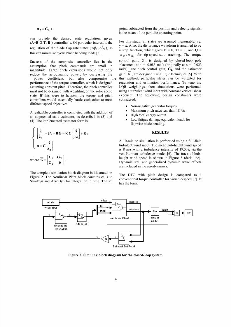
The complete simulation block diagram is illustrated in
Figure 2. The Nonlinear Plant block contains calls to
SymDyn and AeroDyn for integration in time. The set
point, subtracted from the position and velocity signals,
is the mean of the periodic operating point.
For this study, all states are assumed measurable, i.e.
y = x. Also, the disturbance waveform is assumed to be
a step function, which gives F = 0, Θ = 1, and Q =
&
ψ op / w op for tip-speed-ratio tracking. The torque
control gain, G1, is designed by closed-loop pole
placement at s = -0.085 rad/s (originally at s = -0.023
rad/s). The pitch control gain, G2, and the estimator
gain, K , are designed using LQR techniques [5]. With
this method, particular states can be weighted for
regulation and estimation performance. To tune the
LQR weightings, short simulations were performed
using a turbulent wind input with constant vertical shear
exponent. The following design constraints were
considered:
• Non-negative generator torques
• Maximum pitch rates less than 18 °/s• High total energy output
• Low fatigue damage equivalent loads for
flapwise blade bending.
RESULTS
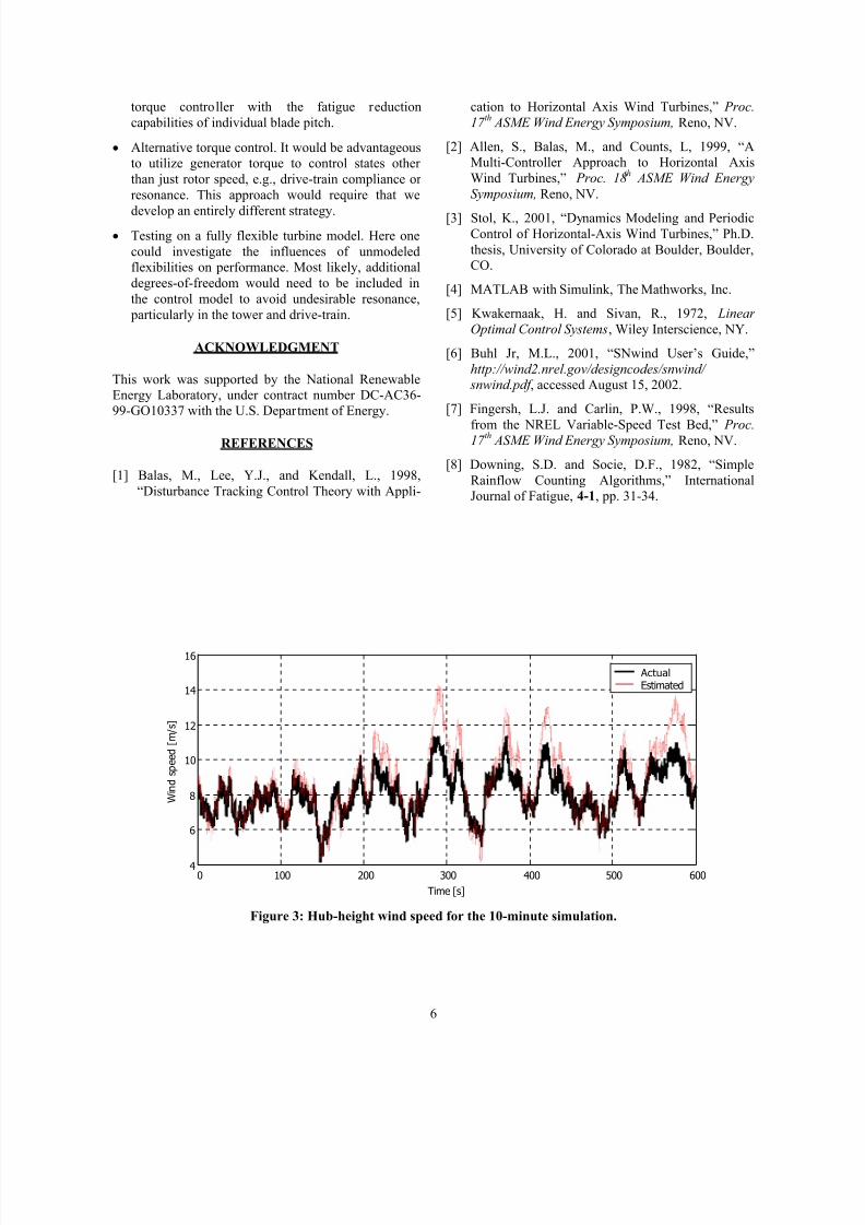
A 10-minute simulation is performed using a full-field
turbulent wind input. The mean hub-height wind speed
is 8 m/s with a turbulence intensity of 19.5%, via the
von Karman turbulence model [6]. The trace of hub-
height wind speed is shown in Figure 3 (dark line).
Dynamic stall and generalized dynamic wake effects
are included in the aerodynamics.
The DTC with pitch design is compared to a
conventional torque controller for variable-speed [7]. It
has the form:
C
Figure 2: Simulink block diagram for the closed-loop system.
4
8/3/2019 Disturbance Tracking and Blade Load Control of Wind Turbines in Variable-Speed Operation
http://slidepdf.com/reader/full/disturbance-tracking-and-blade-load-control-of-wind-turbines-in-variable-speed 7/10
&T = k ψ 2g
where k = ρπR 5C p0= 6389 for the CART model.
32λ 0
Pitch is held constant at -1°.
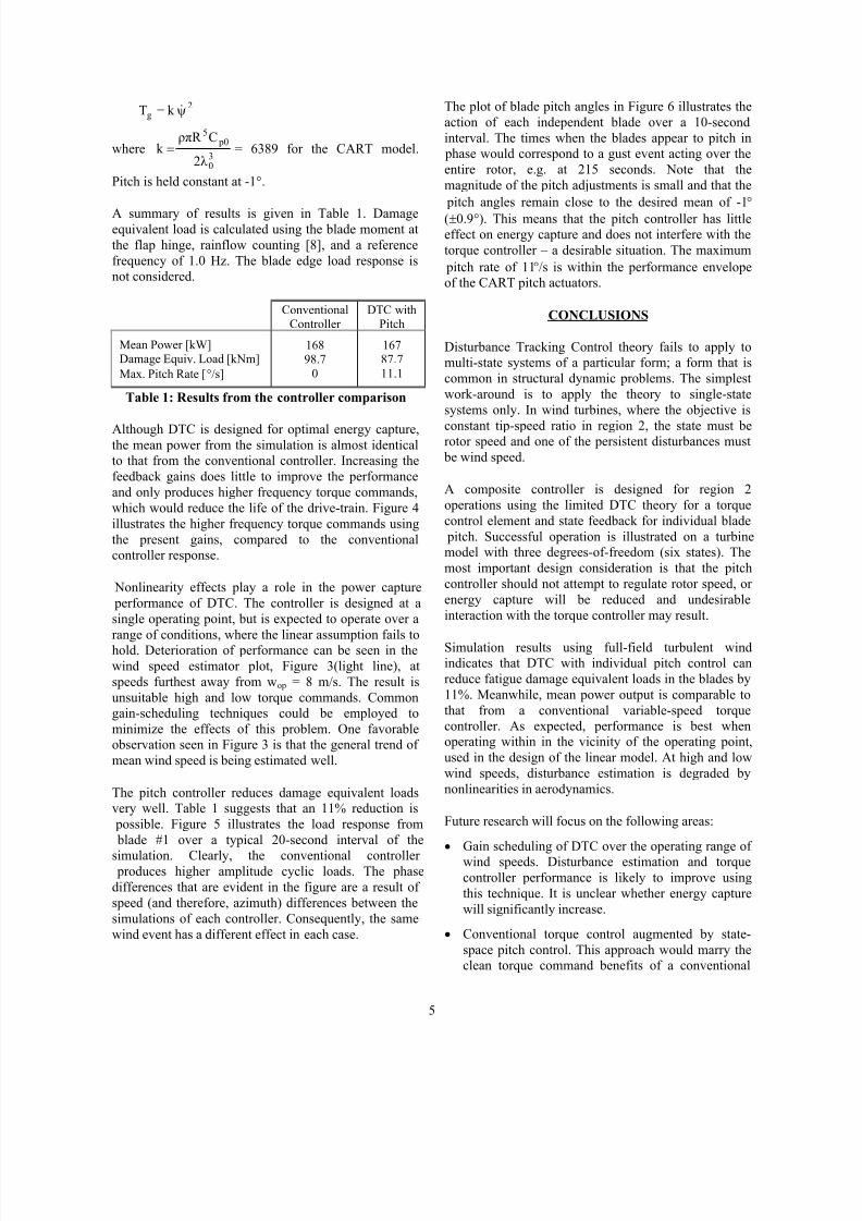
A summary of results is given in Table 1. Damageequivalent load is calculated using the blade moment at
the flap hinge, rainflow counting [8], and a reference
frequency of 1.0 Hz. The blade edge load response is
not considered.
ConventionalController
DTC withPitch
Mean Power [kW]Damage Equiv. Load [kNm]
Max. Pitch Rate [°/s]
16898.7
0
16787.7
11.1
Table 1: Results from the controller comparison
Although DTC is designed for optimal energy capture,
the mean power from the simulation is almost identical
to that from the conventional controller. Increasing the
feedback gains does little to improve the performance
and only produces higher frequency torque commands,
which would reduce the life of the drive-train. Figure 4
illustrates the higher frequency torque commands using
the present gains, compared to the conventional
controller response.
Nonlinearity effects play a role in the power capture
performance of DTC. The controller is designed at a
single operating point, but is expected to operate over a
range of conditions, where the linear assumption fails to
hold. Deterioration of performance can be seen in the
wind speed estimator plot, Figure 3(light line), at
speeds furthest away from wop = 8 m/s. The result is
unsuitable high and low torque commands. Common
gain-scheduling techniques could be employed to
minimize the effects of this problem. One favorable
observation seen in Figure 3 is that the general trend of
mean wind speed is being estimated well.
The pitch controller reduces damage equivalent loads
very well. Table 1 suggests that an 11% reduction is
possible. Figure 5 illustrates the load response from
blade #1 over a typical 20-second interval of thesimulation. Clearly, the conventional controller
produces higher amplitude cyclic loads. The phase
differences that are evident in the figure are a result of
speed (and therefore, azimuth) differences between the
simulations of each controller. Consequently, the same
wind event has a different effect in each case.
The plot of blade pitch angles in Figure 6 illustrates the
action of each independent blade over a 10-second
interval. The times when the blades appear to pitch in
phase would correspond to a gust event acting over the
entire rotor, e.g. at 215 seconds. Note that the
magnitude of the pitch adjustments is small and that the
pitch angles remain close to the desired mean of -1°
(±0.9°). This means that the pitch controller has little
effect on energy capture and does not interfere with the
torque controller – a desirable situation. The maximum
pitch rate of 11°/s is within the performance envelope
of the CART pitch actuators.
CONCLUSIONS
Disturbance Tracking Control theory fails to apply to
multi-state systems of a particular form; a form that is
common in structural dynamic problems. The simplest
work-around is to apply the theory to single-state
systems only. In wind turbines, where the objective is
constant tip-speed ratio in region 2, the state must be
rotor speed and one of the persistent disturbances must
be wind speed.
A composite controller is designed for region 2
operations using the limited DTC theory for a torque
control element and state feedback for individual blade
pitch. Successful operation is illustrated on a turbine
model with three degrees-of-freedom (six states). The
most important design consideration is that the pitch
controller should not attempt to regulate rotor speed, or
energy capture will be reduced and undesirable
interaction with the torque controller may result.
Simulation results using full-field turbulent wind
indicates that DTC with individual pitch control can
reduce fatigue damage equivalent loads in the blades by
11%. Meanwhile, mean power output is comparable to
that from a conventional variable-speed torque
controller. As expected, performance is best when
operating within in the vicinity of the operating point,
used in the design of the linear model. At high and low
wind speeds, disturbance estimation is degraded by
nonlinearities in aerodynamics.
Future research will focus on the following areas:
• Gain scheduling of DTC over the operating range of
wind speeds. Disturbance estimation and torque
controller performance is likely to improve using
this technique. It is unclear whether energy capture
will significantly increase.
• Conventional torque control augmented by state-
space pitch control. This approach would marry the
clean torque command benefits of a conventional
5
8/3/2019 Disturbance Tracking and Blade Load Control of Wind Turbines in Variable-Speed Operation
http://slidepdf.com/reader/full/disturbance-tracking-and-blade-load-control-of-wind-turbines-in-variable-speed 8/10
torque controller with the fatigue reduction cation to Horizontal Axis Wind Turbines,” Proc.
capabilities of individual blade pitch. 17 th
ASME Wind Energy Symposium, Reno, NV.
• Alternative torque control. It would be advantageous [2] Allen, S., Balas, M., and Counts, L, 1999, “A
to utilize generator torque to control states other Multi-Controller Approach to Horizontal Axis
than just rotor speed, e.g., drive-train compliance or Wind Turbines,” Proc. 18th
ASME Wind Energy
resonance. This approach would require that we Symposium, Reno, NV.
develop an entirely different strategy. [3] Stol, K., 2001, “Dynamics Modeling and Periodic
• Testing on a fully flexible turbine model. Here one Control of Horizontal-Axis Wind Turbines,” Ph.D.
could investigate the influences of unmodeled thesis, University of Colorado at Boulder, Boulder,
flexibilities on performance. Most likely, additional CO.
degrees-of-freedom would need to be included in[4] MATLAB with Simulink, The Mathworks, Inc.
the control model to avoid undesirable resonance, particularly in the tower and drive-train. [5] Kwakernaak, H. and Sivan, R., 1972, Linear
Optimal Control Systems, Wiley Interscience, NY.
ACKNOWLEDGMENT [6] Buhl Jr, M.L., 2001, “SNwind User’s Guide,”
http://wind2.nrel.gov/designcodes/snwind/ This work was supported by the National Renewable snwind.pdf , accessed August 15, 2002.Energy Laboratory, under contract number DC-AC36-99-GO10337 with the U.S. Department of Energy. [7] Fingersh, L.J. and Carlin, P.W., 1998, “Results
from the NREL Variable-Speed Test Bed,” Proc.
REFERENCES 17 th
ASME Wind Energy Symposium, Reno, NV.
[1] Balas, M., Lee, Y.J., and Kendall, L., 1998,[8] Downing, S.D. and Socie, D.F., 1982, “Simple
Rainflow Counting Algorithms,” International“Disturbance Tracking Control Theory with Appli- Journal of Fatigue, 4-1, pp. 31-34.
16
14
12
10
8
6
40 100 200 300 400 500 600
Time [s]
ActualEstimated
Figure 3: Hub-height wind speed for the 10-minute simulation.
W i n d s p e e d [ m / s ]
6

8/3/2019 Disturbance Tracking and Blade Load Control of Wind Turbines in Variable-Speed Operation
http://slidepdf.com/reader/full/disturbance-tracking-and-blade-load-control-of-wind-turbines-in-variable-speed 9/10
B l a
d e P i t c h [ d e g ]
B l a d e # 1 b e n d i n g m o m e n t [ k N m ]
G e n e r a t o r T o r q u e [ k N m ]
100
90
80
70
60
50
40
30
20
180
170
160
150
140
130
120
110
100
90
DTC w ith Pitch
Conventional Controller
0 100 200 300 400 500
Time [s]
Figure 4: Generator torque commands.
Conv entional C ontroller
DTC with Pitch
210 212 214 216 218 220 222 224 226 228 230Time [sec]
Figure 5: Blade #1 flap bending moment response.
0
-0.2
-0.4
-0.6
-0.8
-1
-1.2
-1.4
-1.6
-1.8
Blade #1
Blade #2
210 211 212 213 214 215 216 217 218 219 220
Time [sec]
Figure 6: Individual blade pitch commands for the composite controller.
7
600

8/3/2019 Disturbance Tracking and Blade Load Control of Wind Turbines in Variable-Speed Operation
http://slidepdf.com/reader/full/disturbance-tracking-and-blade-load-control-of-wind-turbines-in-variable-speed 10/10
REPORT DOCUMENTATION PAGE Form Approved
OMB NO. 0704-0188
Public reporting burden for this collection of information is estimated to average 1 hour per response, including the time for reviewing instructions, searching existing data sources,gathering and maintaining the data needed, and completing and reviewing the collection of information. Send comments regarding this burden estimate or any other aspect of thiscollection of information, including suggestions for reducing this burden, to Washington Headquarters Services, Directorate for Information Operations and Reports, 1215 JeffersonDavis Highway, Suite 1204, Arlington, VA 22202-4302, and to the Office of Management and Budget, Paperwork Reduction Project (0704-0188), Washington, DC 20503.
1. AGENCY USE ONLY (Leave blank) 2. REPORT DATE
January 2003
3. REPORT TYPE AND DATES COVERED
Conference paper
4. TITLE AND SUBTITLE
Disturbance Tracking and Blade Load Control of Wind Turbines in Variable-SpeedOperation: Preprint
5. FUNDING NUMBERS
WER3.2050
6. AUTHOR(S)
K.A. Stol
7. PERFORMING ORGANIZATION NAME(S) AND ADDRESS(ES)
National Renewable Energy Laboratory1617 Cole Blvd.Golden, CO 80401-3393
8. PERFORMING ORGANIZATIONREPORT NUMBER
NREL/CP-500-33011
9. SPONSORING/MONITORING AGENCY NAME(S) AND ADDRESS(ES) 10. SPONSORING/MONITORING
AGENCY REPORT NUMBER
11. SUPPLEMENTARY NOTES
12a. DISTRIBUTION/AVAILABILITY STATEMENT
National Technical Information ServiceU.S. Department of Commerce5285 Port Royal RoadSpringfield, VA 22161
12b. DISTRIBUTION CODE
13. ABSTRACT (Maximum 200 words)
A composite state-space controller was developed for a multi-objective problem in the variable-speed operation of windturbines. Disturbance Tracking Control theory was applied to the design of a torque controller to optimize energy captureunder the influence of persistent wind disturbances. A limitation in the theory for common multi-state models is described,which led to the design of a complementary pitch controller. The goal of the independent blade pitch design was to minimizeblade root fatigue loads. Simulation results indicate an 11% reduction in fatigue damage using the proposed controllers,compared to a conventional torque-only design. Meanwhile, energy capture is almost identical, partly because of nonlinear effects.
14. SUBJECT TERMS
wind energy; Disturbance Tracking Control theory; state-space controller; blade rootfatigue loads
15. NUMBER OF PAGES
16. PRICE CODE
17. SECURITY CLASSIFICATION
OF REPORT
Unclassified
18. SECURITY CLASSIFICATION
OF THIS PAGE
Unclassified
19. SECURITY CLASSIFICATION
OF ABSTRACT
Unclassified
20. LIMITATION OF ABSTRACT
UL
NSN 7540-01-280-5500 Standard Form 298 (Rev. 2Prescribed by ANSI Std. Z
29