Embed Size (px)
Citation preview
..........................................................................
Cahier technique no. 177
Disturbances in electronic systemsand earthing systems
J. Delaballe
Collection Technique
"Cahiers Techniques" is a collection of documents intended for engineersand technicians, people in the industry who are looking for more in-depthinformation in order to complement that given in product catalogues.
Furthermore, these "Cahiers Techniques" are often considered as helpful"tools" for training courses.They provide knowledge on new technical and technological developmentsin the electrotechnical field and electronics. They also provide betterunderstanding of various phenomena observed in electrical installations,systems and equipments.Each "Cahier Technique" provides an in-depth study of a precise subject inthe fields of electrical networks, protection devices, monitoring and controland industrial automation systems.
The latest publications can be downloaded from the Schneider Electricinternet web site.Code: http://www.schneider-electric.comSection: Experts' place
Please contact your Schneider Electric representative if you want either a"Cahier Technique" or the list of available titles.
The "Cahiers Techniques" collection is part of the Schneider Electric’s"Collection technique".
ForewordThe author disclaims all responsibility subsequent to incorrect use ofinformation or diagrams reproduced in this document, and cannot be heldresponsible for any errors or oversights, or for the consequences of usinginformation and diagrams contained in this document.
Reproduction of all or part of a "Cahier Technique" is authorised with theprior consent of the Scientific and Technical Division. The statement"Extracted from Schneider Electric "Cahier Technique" no. ....." (pleasespecify) is compulsory.
no. 177Disturbances in electronic systemsand earthing systems
ECT 177(e) first issue, November 2002
Jacques DELABALLE
Obtained his Ph.D from the University of Limoges in 1980, started atMerlin-Gerin in 1986 after seven years at Thomson.Initially headed the EMC laboratory of the Schneider ElectricCorporate Research Organization, now standardization delegate.He is also secretary of Sub-Committee 77B (HF phenomena) of theInternational Electrotechnical Commission (IEC).
Cahier Technique Schneider Electric no. 177 / p.2
Lexicon
CES:Communicating Electronic System.
EBS:Equipotential Bonding System.
Electro shock:Application of voltage between two parts of thebody.
Electrocution:Electro shock resulting in death.
EMC:Electromagnetic Compatibility.
GFLD:Ground Fault Location Device.
IEC:International Electrotechnical Commission.
I∆n:Value of operating threshold for an RCD.
LV:Low Voltage.
MV:Medium Voltage (1 to 35 kV according toCENELEC), in France HTA (1 to 50 kV).
PIM:Permanent Insulation Monitor.
RCD/HS:High Sensitivity Residual Current Devices(i 30 mA).
RCD/LS:Low Sensitivity Residual Current Devices.
RCD/MS:Medium Sensitivity Residual Current Devices.
SCPD:Short-Circuit Protection Device.
Cahier Technique Schneider Electric no. 177 / p.3
Disturbances in electronic systemsand earthing systems
In today’s society, power and signal processing (analog, digital) electronicsare omnipresent in all types of building.Information technology, automation control, hierarchical control andmonitoring systems, weave a web around the electrical networks thatsupply them.Although non-linear loads (rectifiers, variable speed drives, powercontrollers, switch mode power supplies, etc) create disturbances,“low current” electronic systems are affected by all kinds of electrical andmagnetic disturbances.The choice of Earthing System is an important factor for electronicsystems, especially when they use digital links (bus) to communicate.This “Cahier Technique” first examines the disturbance found onLV installations and then looks at the advantages and disadvantages ofearthing systems in terms of the cohabitation of “high” and “low” currents.
Contents
1 Introduction p. 4
2 Disturbances originating outside 2.1 Telluric currents p. 5LV network 2.2 Stray earth currents (50 Hz) p. 5
2.3 Breakdown current in HV/LV transformers p. 5
2.4 Overvoltages due to switching on the MV network p. 6
2.5 Harmonic voltages p. 6
2.6 Lightning voltages and currents p. 6
2.7 HF disturbances p. 7
3 Disturbances originating within 3.1 Harmonic currents and voltages p. 8the LV network 3.2 Overvoltages due to switching (differential mode) on the p. 9
LV network
3.3 High fault currents p. 9
4 Cohabitation of “ high currents” and 4.1 Limiting emitted disturbances p. 10“ low currents” 4.2 Reduction of couplings p. 11
4.3 Exposed conductive parts and earths p. 14
4.4 Ideal earth and EBS system p. 15
5 Earthing systems and communicating 5.1 Earthing systems, CES and Low Frequency - LF - disturbances p. 16electronic systems (CES) 5.2 Earthing systems, CES and High Frequency - HF disturbances p. 18
6 Conclusion p. 22
Appendix 1: earthing systems according to p. 23IEC 60364
Appendix 2: example of creating a location p. 25free from electromagnetic disturbances
Bibliography p. 27
Cahier Technique Schneider Electric no. 177 / p.4
1. Introduction
An electrical wave is characterized by:c its frequency,c its voltage,c its intensity.
In the large supply networks of industrializedcountries, the frequency is perfectly stable.It may vary when network splitting on a privateinstallation involves the use of replacementsources, but this variation has little effect on theearthing systems and protective equipmentrequired.
It makes no difference whether the frequency is50 or 60 Hz. However, certain networks distributepower at 400 Hz, in which case the influence ofthe earth leakage capacities may need to be takeninto account when selecting the earthing system.
During normal operation and in the event of aninsulation fault, the currents and voltages presentin electrical installations are essentially variablein terms of value and waveform, which may becompletely different from the sine wave. This isparticularly true for currents resulting from aninsulation fault downstream of a static convertor(see “Cahier Technique” no. 114).
Phenomena that distort or disturb the “mains” sinewave have many different origins and, dependingon the earthing system, may result in differenttypes of disturbances in the LV distribution, andalso in communicating electronic systems.
Three earthing systems are defined bypublication IEC 60364. These are discussed in“Cahiers Techniques” no. 172 and no. 173 and asummary is included in appendix 1.
Cahier Technique Schneider Electric no. 177 / p.5
2 Disturbances originating outside LV networks
2.1 Telluric currents
These are currents with a frequency less than50 Hz, caused by solar magnetic storms. Theycirculate deep in the earth. They can disturbtransmission line protection devices, but cause
few problems for small-scale LV networks andhave no effect when these networks have onlyone earth connection.
2.2 Stray earth currents (50 Hz)
These originate during insulation faults in MVor HV networks used with an impedance-earthed neutral point connection, and also incertain electrical traction installations where thefeedback current passes into the earth.Special care must therefore be taken withLV installations located near MV/LV transformersubstations and electrified railway lines.They can cause disturbances due to common-
impedance in the operation of “low current”systems spread over a wide geographical area,especially if these systems do not have a singlepotential reference (as is the case with severalearth connections).
It should be noted that stray currents have beenone of the reasons for the discontinuation ofearth voltage relays sensitive to error voltage.
2.3 Breakdown current in MV/LV transformers
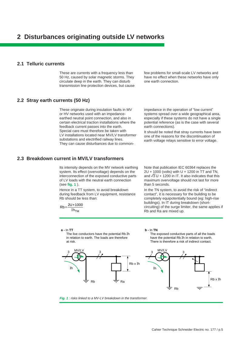
Its intensity depends on the MV network earthingsystem. Its effect (overvoltage) depends on theinterconnection of the exposed conductive partsof LV loads with the neutral earth connection(see fig. 1 ).
Hence in a TT system, to avoid breakdownduring feedback from LV equipment, resistanceRb should be less than:
RbU
hTM= +2 1000
I
Note that publication IEC 60364 replaces the2U + 1000 (volts) with U + 1200 in TT and TN,and eU + 1200 in IT. It also indicates that thismaximum overvoltage should not last for morethan 5 seconds.
In the TN system, to avoid the risk of “indirectcontact”, it is necessary for the building to becompletely equipotentially bound (eg: high-risebuildings). In IT during breakdown (short-circuiting) of the surge limiter, the same applies ifRb and Ra are mixed up.
Fig. 1 : risks linked to a MV-LV breakdown in the transformer.
Ih
Rb
3 3
Rb x Ih
a - In TT The live conductors have the potential Rb.Ih in relation to earth. The loads are therefore at risk.
Ih
Rb
3 3
Rb x Ih
b - In TN The exposed conductive parts of all the loads have the potential Rb.Ih in relation to earth. There is therefore a risk of indirect contact.
MV/LV MV/LV
Ra
Cahier Technique Schneider Electric no. 177 / p.6
2.4 Overvoltages due to switching on the MV network
Overvoltages with an MV origin are significantlyattenuated due to the low pass band of the MV/LV transformer (in differential mode). Any effects
2.5 Harmonic voltages
MV networks are disturbed by generators ofharmonics found in various subscribers. As aresult, distortion occurs in the MV voltage wave,and consequently the LV wave.
LV loads from a non-disturbing subscribertherefore absorb harmonic currents, and currentsresulting from an insulation fault are also distorted.
Electricity distributors are nowadays veryconcerned about deterioration of the MV wave,despite the fact that star-delta transformers(Dy11) do not transmit third order harmonicsand their multiples from LV to MV, etc.
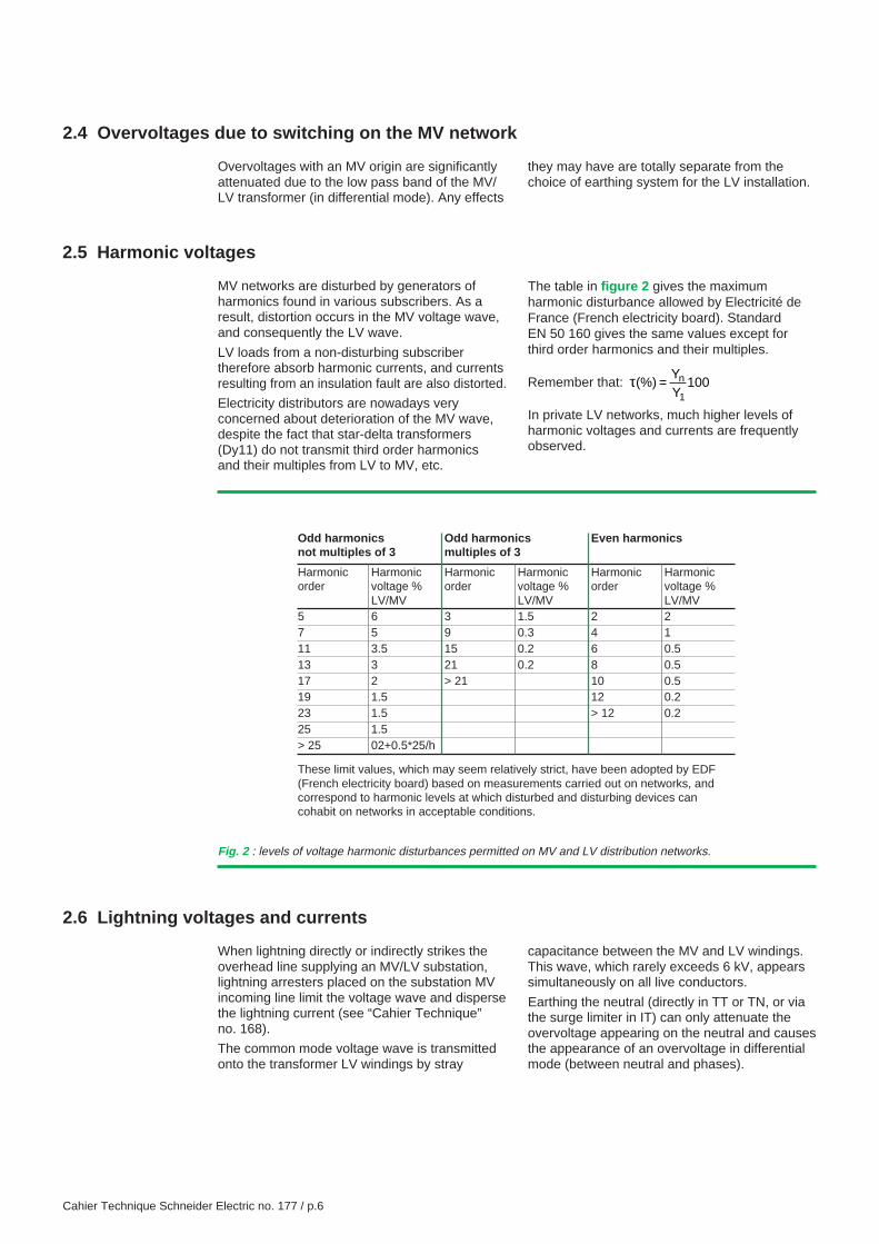
The table in figure 2 gives the maximumharmonic disturbance allowed by Electricité deFrance (French electricity board). StandardEN 50 160 gives the same values except forthird order harmonics and their multiples.
Remember that: τ(%)YY
100n
1=
In private LV networks, much higher levels ofharmonic voltages and currents are frequentlyobserved.
Odd harmonics Odd harmonics Even harmonicsnot multiples of 3 multiples of 3
Harmonic Harmonic Harmonic Harmonic Harmonic Harmonicorder voltage % order voltage % order voltage %
LV/MV LV/MV LV/MV5 6 3 1.5 2 27 5 9 0.3 4 111 3.5 15 0.2 6 0.513 3 21 0.2 8 0.517 2 > 21 10 0.519 1.5 12 0.223 1.5 > 12 0.225 1.5> 25 02+0.5*25/h
These limit values, which may seem relatively strict, have been adopted by EDF(French electricity board) based on measurements carried out on networks, andcorrespond to harmonic levels at which disturbed and disturbing devices cancohabit on networks in acceptable conditions.
Fig. 2 : levels of voltage harmonic disturbances permitted on MV and LV distribution networks.
2.6 Lightning voltages and currents
When lightning directly or indirectly strikes theoverhead line supplying an MV/LV substation,lightning arresters placed on the substation MVincoming line limit the voltage wave and dispersethe lightning current (see “Cahier Technique”no. 168).
The common mode voltage wave is transmittedonto the transformer LV windings by stray
capacitance between the MV and LV windings.This wave, which rarely exceeds 6 kV, appearssimultaneously on all live conductors.
Earthing the neutral (directly in TT or TN, or viathe surge limiter in IT) can only attenuate theovervoltage appearing on the neutral and causesthe appearance of an overvoltage in differentialmode (between neutral and phases).
they may have are totally separate from thechoice of earthing system for the LV installation.
Cahier Technique Schneider Electric no. 177 / p.7
2.7 HF disturbances
In addition to lightning strikes, radio-linktransmitters (radio, TV, CB, walkie-talkies andGSM) generate permanent or temporaryelectromagnetic fields.
Normal switching, or short-circuiting, of breakingdevices generates pulse electromagnetic fields.For example, 40 kV/m fields have been recordedat a distance of 1 m from an MV cubicle.
These permanent, temporary or pulse fieldsresult in conducted interference, due to antennaor loop effects. This interference may disturb, oreven damage, autonomous electronic equipment(if it does not have sufficient immunity) andcommunicating electronic systems (if the “lowcurrent” links have not been created correctly).
If there is a risk of overvoltage, the use oflightning arresters between all live conductorsand earth is therefore strongly recommended,regardless of the earthing system (see “CahierTechnique” no. 179).The links must be as short as possible:∆U = LωÎwhere L = 1 µH/m and ω = 2.2/tm, tm being thecurrent rise time.
The lightning current leakage to earth createsovervoltages in the LV network similar to whathappens during transformer breakdown (see fig. 1),although with some attenuation due to the straycapacitance as the wave travels over the network.
Remember that IEC 60364 defines four levels ofnominal impulse withstand voltage for electricalequipment (wave test 1.2/50 ms): 1.5 - 2.5 - 4 and6 kV.
Cahier Technique Schneider Electric no. 177 / p.8
3 Disturbances originating within the LV networks
3.1 Harmonic currents and voltages
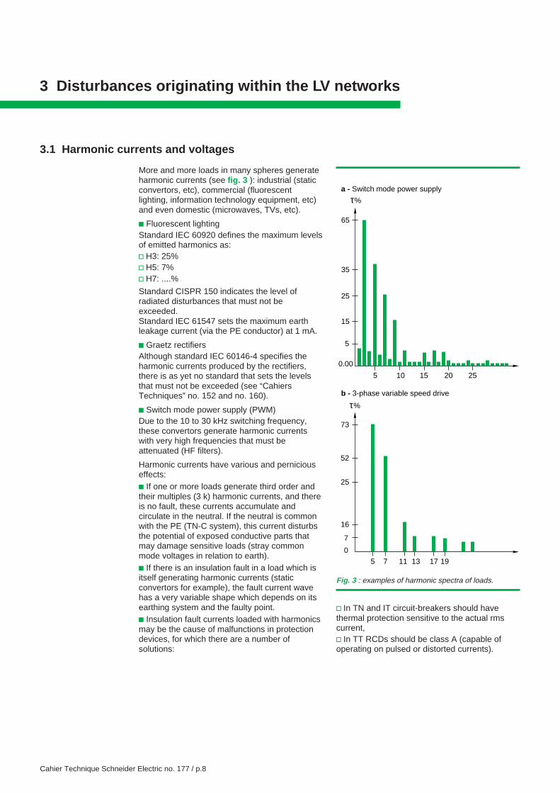
More and more loads in many spheres generateharmonic currents (see fig. 3 ): industrial (staticconvertors, etc), commercial (fluorescentlighting, information technology equipment, etc)and even domestic (microwaves, TVs, etc).
c Fluorescent lightingStandard IEC 60920 defines the maximum levelsof emitted harmonics as:v H3: 25%v H5: 7%v H7: ....%
Standard CISPR 150 indicates the level ofradiated disturbances that must not beexceeded.Standard IEC 61547 sets the maximum earthleakage current (via the PE conductor) at 1 mA.
c Graetz rectifiersAlthough standard IEC 60146-4 specifies theharmonic currents produced by the rectifiers,there is as yet no standard that sets the levelsthat must not be exceeded (see “CahiersTechniques” no. 152 and no. 160).
c Switch mode power supply (PWM)Due to the 10 to 30 kHz switching frequency,these convertors generate harmonic currentswith very high frequencies that must beattenuated (HF filters).
Harmonic currents have various and perniciouseffects:c If one or more loads generate third order andtheir multiples (3 k) harmonic currents, and thereis no fault, these currents accumulate andcirculate in the neutral. If the neutral is commonwith the PE (TN-C system), this current disturbsthe potential of exposed conductive parts thatmay damage sensitive loads (stray commonmode voltages in relation to earth).c If there is an insulation fault in a load which isitself generating harmonic currents (staticconvertors for example), the fault current wavehas a very variable shape which depends on itsearthing system and the faulty point.c Insulation fault currents loaded with harmonicsmay be the cause of malfunctions in protectiondevices, for which there are a number ofsolutions:
v In TN and IT circuit-breakers should havethermal protection sensitive to the actual rmscurrent,v In TT RCDs should be class A (capable ofoperating on pulsed or distorted currents).
65
35
25
15
5
0.00
0
5 10 15 20 25
τ%
73
52
25
16
5 11 19
7
7 13 17
τ%
a - Switch mode power supply
b - 3-phase variable speed drive
Fig. 3 : examples of harmonic spectra of loads.
Cahier Technique Schneider Electric no. 177 / p.9
3.2 Overvoltages due to switching (differential mode) on the LV network
These are mainly the result of breaking ofnormal or fault currents, for example during:c Opening of control circuits for contactors andrelays not fitted with an RC filter;c Breaking of short-circuit currents by SCPDswith very high peak arc voltages (certain fuses).Note that breaking an insulation fault current in
the TN system can result in a common modeovervoltage.
These overvoltages can disturb the operation ofcertain sensitive switchgear… includingprotection equipment with an auxiliary source,which should have built-in immunity.
3.3 High fault currents
These are mainly short-circuit currents betweenlive conductors (or via the PE in TN and on thesecond fault in IT).
If the various conductors are ungrouped andsingle-wire, the magnetic field which is thenradiated by the live conductors (and by the PE inTN and IT) can cause accidental operation of
electronic equipment, especially when thesedevices are near electrical trunking or connectedby “low current” links.
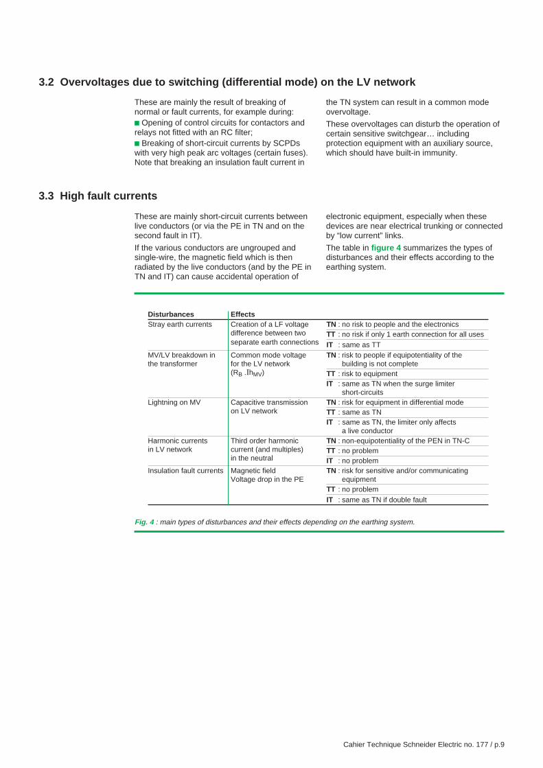
The table in figure 4 summarizes the types ofdisturbances and their effects according to theearthing system.
Disturbances EffectsStray earth currents Creation of a LF voltage TN : no risk to people and the electronics
difference between two TT : no risk if only 1 earth connection for all usesseparate earth connections IT : same as TT
MV/LV breakdown in Common mode voltage TN : risk to people if equipotentiality of thethe transformer for the LV network building is not complete
(RB .IhMV) TT : risk to equipmentIT : same as TN when the surge limiter
short-circuitsLightning on MV Capacitive transmission TN : risk for equipment in differential mode
on LV network TT : same as TNIT : same as TN, the limiter only affects
a live conductorHarmonic currents Third order harmonic TN : non-equipotentiality of the PEN in TN-Cin LV network current (and multiples) TT : no problem
in the neutral IT : no problemInsulation fault currents Magnetic field TN : risk for sensitive and/or communicating
Voltage drop in the PE equipmentTT : no problemIT : same as TN if double fault
Fig. 4 : main types of disturbances and their effects depending on the earthing system.
Cahier Technique Schneider Electric no. 177 / p.10
4 Cohabitation of “ high currents” and “ low currents”
Electronics are used everywhere nowadays: insensors, actuators, process control and monitoringsystems, of buildings and electrical distribution.
These devices are supplied by the LV networkand should not be sensitive to the various typesof disturbances seen earlier.
Responsible manufacturers are fully aware ofhow to provide immunity for these devices, inother words to control their susceptibility toelectromagnetic phenomena. To this end, theyrefer to the electromagnetic compatibilitystandards, for example, IEC 61000 (see “CahierTechnique” no. 149).
At the same time, standardization aims to minimizeinterference emitted by disturbing devices.Standard CISPR 11 is an example of this.
Nonetheless, the standardized cohabitationbetween disturbing devices and disturbed
devices has not been resolved since, in theelectrical domain, certain questions remain:
c How does an electrical installation behavewhen it is producing disturbances?
... When the way the installation is created andthe choice of earthing system are thedetermining factors.
c In this context, how can we attenuatedisturbances and their effects on sensitive(electronic) equipment?
... This is where the problem lies: the satisfactorycoexistence of electrotechnical and electronicequipment, in other words, of high currents andlow currents. For this to be satisfactory,disturbances must be minimized at source andcouplings between the source and the potentialvictim avoided.
4.1 Limiting emitted disturbances
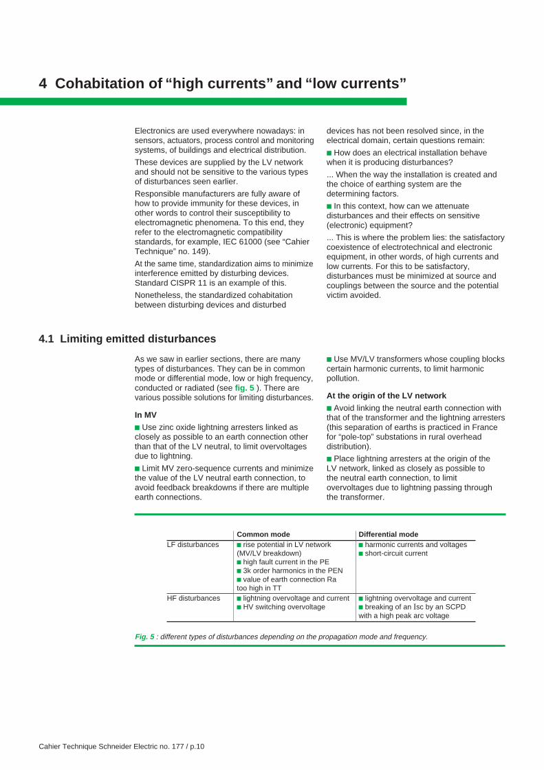
As we saw in earlier sections, there are manytypes of disturbances. They can be in commonmode or differential mode, low or high frequency,conducted or radiated (see fig. 5 ). There arevarious possible solutions for limiting disturbances.
In MV
c Use zinc oxide lightning arresters linked asclosely as possible to an earth connection otherthan that of the LV neutral, to limit overvoltagesdue to lightning.
c Limit MV zero-sequence currents and minimizethe value of the LV neutral earth connection, toavoid feedback breakdowns if there are multipleearth connections.
Fig. 5 : different types of disturbances depending on the propagation mode and frequency.
Common mode Differential modeLF disturbances c rise potential in LV network c harmonic currents and voltages
(MV/LV breakdown) c short-circuit currentc high fault current in the PEc 3k order harmonics in the PENc value of earth connection Ratoo high in TT
HF disturbances c lightning overvoltage and current c lightning overvoltage and currentc HV switching overvoltage c breaking of an Isc by an SCPD
with a high peak arc voltage
c Use MV/LV transformers whose coupling blockscertain harmonic currents, to limit harmonicpollution.
At the origin of the LV network
c Avoid linking the neutral earth connection withthat of the transformer and the lightning arresters(this separation of earths is practiced in Francefor “pole-top” substations in rural overheaddistribution).
c Place lightning arresters at the origin of theLV network, linked as closely as possible tothe neutral earth connection, to limitovervoltages due to lightning passing throughthe transformer.
Cahier Technique Schneider Electric no. 177 / p.11
c Avoid the TN-C earthing system as the PENcarries harmonic currents (third order andmultiples) and therefore disturbs the potentialreference provided by the PE for electronicequipment.
In the LV network
To minimize radiated magnetic fields:c As far as possible, avoid using single-polecables that generate a significant magnetic fieldin the event of a short-circuit.
c Do not separate the PE on live conductors, oreven better, use cables that incorporate the PE.
c Do not use shielded cables whose casingforms the PE or place the cables in steel tubesacting as a protective conductor (the fieldradiated by the live conductors is blocked andthe PE generates a magnetic field).
c Ideally use earthing systems that minimizeinsulation fault currents (reduction of themagnetic field).
c Minimize the power-up current of capacitorbanks (shock resistors or inductances).
c In IT, if the network is small-scale, use animpedance (impedance earthed) to “fix” theneutral potential to earth.
c Run the power cables along metallic cabletrays, paying special attention to the continuityof this “ground plane” and its connection withthe main equipotential bonding (horizontal andvertical routing), as this significantly reduceselectromagnetic radiation.
c Trap overvoltages:v by placing RC circuits on the coils of contactors,relays, etc.v by protecting sensitive equipment with lightningarresters.
In loads
All electrical equipment is covered by standardslimiting emission of HF and LF disturbanceswhen connected to the public LV distributionnetwork.There are numerous solutions for minimizingharmonic currents: passive or active filters, staticconvertor with sinusoidal sampling, etc.
4.2 Reduction of couplings
Not all disturbances can be attenuated atsource: to avoid malfunctions in electronicequipment, transfers between the transmitterand the disturbed device must be minimized.
There are several types of couplings, and to
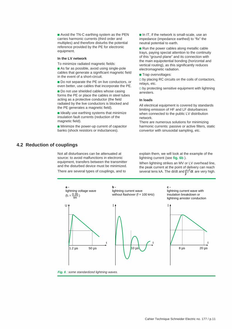
explain them, we will look at the example of thelightning current (see fig. 6b ).
When lightning strikes an MV or LV overhead line,the peak current at the point of delivery can reachseveral tens kA. The di/dt and I2∫ dt are very high.
Fig. 6 : some standardized lightning waves.
t
U
50 µs1.2 µs
t
I
20 µs8 µs
t
I
10 µs
b - lightning current wavewithout flashover (f = 100 kHz)
a - lightning voltage wave
(fo = ) 0.35tm
c - lightning current wave withinsulation breakdown orlightning arrester conduction
Cahier Technique Schneider Electric no. 177 / p.12
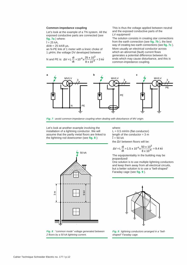
Common-impedance coupling
Let’s look at the example of a TN system. All theexposed conductive parts are connected (seefig. 7a ) where:Î = 25 kA,di/dt = 25 kA/8 µs,an N-PE link of 1 meter with a lineic choke of1 µH/m; the voltage DV developed between
N and PE is: ∆V Ldidt
10 x25 x 10
8 x 10 -6
3
-6= = =3 kv
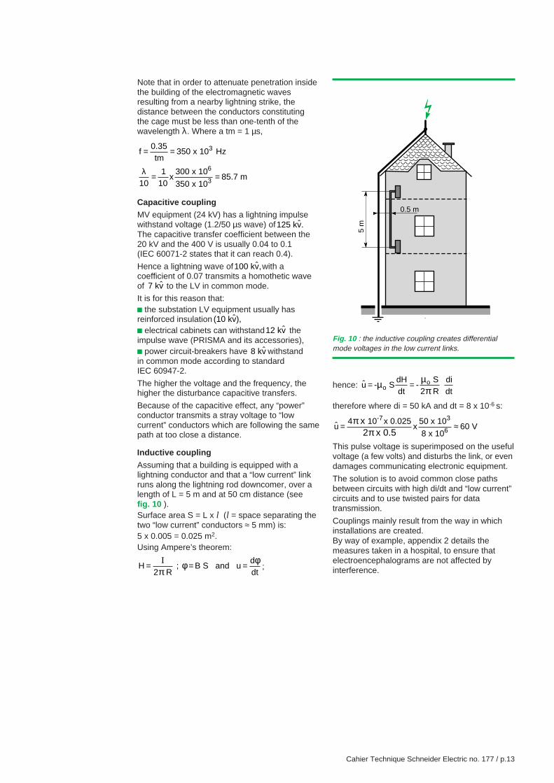
Let’s look at another example involving theinstallation of a lightning conductor. We willassume that the partly metal floors are linked tothe lightning rod downcomer (see fig. 8 ):
MV/LV3
PEN
MV/LV3
PE
MV/LV3
PE
a b c
This is thus the voltage applied between neutraland the exposed conductive parts of theLV equipment!The solution consists in creating star connectionsfrom the earth connection (see fig. 7b ), the bestway of creating two earth connections (see fig. 7c ).More usually an electrical conductor acrosswhich an abnormal (fault) current flowsgenerates a potential difference between itsends which may cause disturbance, and this iscommon-impedance coupling.
Fig. 7 : avoid common-impedance coupling when dealing with disturbance of MV origin.
3 m
9 kV
50 kA
Fig. 8 : “common mode” voltage generated between2 floors by a 50 kA lightning current.
where:L = 0.5 mH/m (flat conductor)length of the conductor = 3 mÎ = 50 kAthe ∆V between floors will be:
∆V Ldidt
1.5 x 1050 x 10
8 x 109.4 kv-6
3
-6= = =x ˆ
The equipotentiality in the building may bejeopardized!One solution is to use multiple lightning conductorsand keep them away from all electrical circuits,but a better solution is to use a “bell-shaped”Faraday cage (see fig. 9 ).
Fig. 9 : lightning conductors arranged in a “bell-shaped” Faraday cage.
Cahier Technique Schneider Electric no. 177 / p.13
Note that in order to attenuate penetration insidethe building of the electromagnetic wavesresulting from a nearby lightning strike, thedistance between the conductors constitutingthe cage must be less than one-tenth of thewavelength λ. Where a tm = 1 µs,
f0.35tm
350 x 10 Hz
101
10300 x 10
350 x 1085.7 m
3
6
3
= =
= =λx
Capacitive couplingMV equipment (24 kV) has a lightning impulsewithstand voltage (1.2/50 µs wave) of125 kv.ˆThe capacitive transfer coefficient between the20 kV and the 400 V is usually 0.04 to 0.1(IEC 60071-2 states that it can reach 0.4).
Hence a lightning wave of100 kv,ˆ with acoefficient of 0.07 transmits a homothetic waveof 7 kv to the LV in common mode.
It is for this reason that:c the substation LV equipment usually hasreinforced insulation (10 kv),ˆ
c electrical cabinets can withstand12 kv theimpulse wave (PRISMA and its accessories),c power circuit-breakers have 8 kv withstandin common mode according to standardIEC 60947-2.
The higher the voltage and the frequency, thehigher the disturbance capacitive transfers.
Because of the capacitive effect, any “power”conductor transmits a stray voltage to “lowcurrent” conductors which are following the samepath at too close a distance.
Inductive coupling
Assuming that a building is equipped with alightning conductor and that a “low current” linkruns along the lightning rod downcomer, over alength of L = 5 m and at 50 cm distance (seefig. 10 ).Surface area S = L x l (l = space separating thetwo “low current” conductors ≈ 5 mm) is:5 x 0.005 = 0.025 m2.Using Ampere’s theorem:
H2 R
; B S and ud
= = =I
πφ φ
dt;
hence: u - SdHdt
- S
2 R
didto
o
= =µ µ
πtherefore where di = 50 kA and dt = 8 x 10⁻⁶ s:
u4 10 x 0.025
x50 x 10
8 x 1060 V
x 2 x 0.5
-7 3
6= ≈ππ
This pulse voltage is superimposed on the usefulvoltage (a few volts) and disturbs the link, or evendamages communicating electronic equipment.
The solution is to avoid common close pathsbetween circuits with high di/dt and “low current”circuits and to use twisted pairs for datatransmission.
Couplings mainly result from the way in whichinstallations are created.By way of example, appendix 2 details themeasures taken in a hospital, to ensure thatelectroencephalograms are not affected byinterference.
Fig. 10 : the inductive coupling creates differentialmode voltages in the low current links.
5 m
0.5 m
Cahier Technique Schneider Electric no. 177 / p.14
4.3 Exposed conductive parts and earths
To assist comprehension of the followingsections, here are some definitions:
c earth (deep): conductive part of the earthwhose electrical potential at each point isconsidered, by convention, to be zero;
c earth connection: conducting body or set ofconducting bodies in close contact with theground and providing an electrical link to it;
c earth network: set of protective earthconductors (PE) linked to an earth connection,whose purpose is to prevent the appearance of adangerous voltage between electrical exposedconductive parts and the earth in the event of aninsulation fault (indirect contact);
c electrical exposed conductive part: conductivepart of an electrical device that can become livein the event of an insulation fault;
c parallel earthing conductor: EBS or conductivestructure (meshed floor, cable tray or shielding, etc)
that runs in parallel with a “low current” cableand protects it by mitigating electromagnetic(HF) couplings or common-impedance couplings;
c functional bonding conductor (FBC):conductive part of an electronic device that actsas a screen and often a potential reference(zero volt). Note that a class II device does nothave an electrical exposed conductive part, butmay have a functional bonding conductor;
c functional equipotential bonding system:set of parallel earthing conductors andconductive structures in a building whichprovide equipotentiality and act as a screenagainst disturbances.
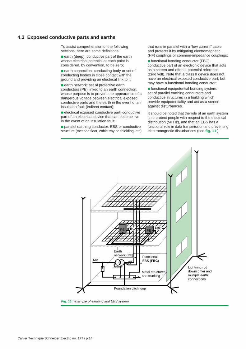
It should be noted that the role of an earth systemis to protect people with respect to the electricaldistribution (50 Hz), and that an EBS has afunctional role in data transmission and preventingelectromagnetic disturbances (see fig. 11 ).
Fig. 11 : example of earthing and EBS system.
PEPE
MV
Metal structuresand trunking
Foundation ditch loop
Lightning rod downcomer and multiple earthconnections
Earth network (PE) Functional
EBS (FBC)
FBC FBC
Cahier Technique Schneider Electric no. 177 / p.15
4.4 Ideal earth and EBS system
The system in figure 11 is an example of this forthe following reasons.
c External disturbances (lightning, switching,HV/exposed conductive part breakdown) have aminor effect on the building equipment, since:v there are multiple lightning rod downcomersand multiple triangular crossbracing earthconnections;v the various “electrical” earth connections arearranged in a star around a single earthconnection.
c The PE conductor (regardless of the earthingsystem) does not disturb the electronic functionalbonding conductors, since:v there is no common-impedance coupling sincethe earth network - PE - is separated from thefunctional equipotential bonding system.In practice, this separation is often provided atfloor level but not always for risers;v its radiated field can be significantly reducedwhen it is in the same cable as the live conductors,with the cable placed on metallic cable tray withelectrical continuity, and this cable tray connectedto the PE at the origin of the installation.
c All the “low current” cables running across themeshed floor (mitigating effect) at a distancefrom the power circuits (u 30 cm) avoid magneticcoupling effects. The same applies to floor
feedthroughs (inter-floor links) with “low current”cables circulating in metallic cable tray thatfollows the “functional bonding conductors”.
Note
c A parallel earthing equipotential bondingconductor can replace a meshed floor orenhance its effect to minimize the effects of anyHF loops.
c The earth network - PE - and the functionalequipotential bonding system can constitute asingle network given two essential conditions:v if there is no HF disturbances, high dv/dt andhigh di/dt,v if the fault currents in the PE or PEN are weakand free of harmonics.
Certain EMC specialists indicate that even ifthese conditions are not met, the EBS and earthnetworks can be closely linked. This is oncondition that the floors, structures and trunkingare correctly meshed (pursuit of totalequipotentiality by dividing currents andminimizing loops).
This solution is difficult to implement in large-scale projects (interconnection of reinforcingrods and all metallic door frames), but may besuitable for very specialized buildings such ascomputer centers and telephone exchanges.
Cahier Technique Schneider Electric no. 177 / p.16
5 Earthing systems and communicating electronic systems (CES)
In the previous section, we discussed cohabitationof electrotechnical installations and electronicswitchgear. The situation becomes morecomplicated with the development of digital linksthat bring electronic devices together incommunicating control and monitoring systems.In this section, we will examine in more detail theproblems that LV network earthing systems cancause for communicating electronic systems.However it should be remembered that:
c Before the development of microprocessors,there were few communicating systems, andthese were locally based (links between sensorsand measurement apparatus). They used lowfrequency analog signals (0-10 V, 4-20 mA, etc)and were sensitive to LF disturbances, hencethe connection of exposed conductive parts in astar to avoid common mode couplings.In addition, there were little HF disturbances,and the induced voltages were easy to filter out.
c Nowadays, links between electronic devicesare digital (bus), high frequency and with a verylow electrical level. They are increasinglynumerous and cover wider and wider areas(PC networks, “intelligent” sensors-actuators,technical management system, etc).
c Depending on the earthing system used, themethod of connecting functional bondingconductors and related runs of “low current” linksin relation to the power distribution, the followingmay be observed:v the existence of common-impedancedisturbance due to fault currents in the PE,v the creation of extended loops (with digitallinks) which are therefore highly receptive todisturbance emitted by devices transmitting highfrequency signals (normal or interference).
5.1 Earthing systems, CES and Low Frequency - LF - disturbances
Electronic equipment frequently requires anelectrical power supply, and its electrical exposedconductive parts and functional bonding conductorsare therefore linked to the earth network (PE),a network that follows the electrical network treestructure. LF disturbances then appear in thenetwork by common-impedance type coupling,or by induction (close parallel runs).
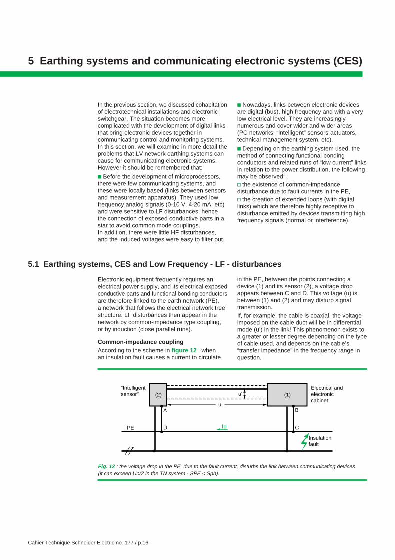
Common-impedance couplingAccording to the scheme in figure 12 , whenan insulation fault causes a current to circulate
in the PE, between the points connecting adevice (1) and its sensor (2), a voltage dropappears between C and D. This voltage (u) isbetween (1) and (2) and may disturb signaltransmission.If, for example, the cable is coaxial, the voltageimposed on the cable duct will be in differentialmode (u’) in the link! This phenomenon exists toa greater or lesser degree depending on the typeof cable used, and depends on the cable’s“transfer impedance” in the frequency range inquestion.
"Intelligentsensor"
Electrical andelectroniccabinet
CDPE
Insulationfault
Id
u
u'
B
(1)(2)
A
Fig. 12 : the voltage drop in the PE, due to the fault current, disturbs the link between communicating devices(it can exceed Uo/2 in the TN system - SPE < Sph).
Cahier Technique Schneider Electric no. 177 / p.17
c In TN-C, currents circulating in the neutral,therefore in the PEN, cause significant variationsin the potential reference of the various devicesin the CES. This earthing system is not suitable,especially if harmonic currents are circulating inthe neutral, unless the functional equipotentialbonding system is separated completely fromthe earth system, which is undesirable in termsof the equipotentiality of the installation.
c In TN-S and also in TN-C, insulation faultsresult in the circulation of short-circuit currents(with high di/dt) in the PE which:v modify the potential reference of CESs (seeprevious example),v may cause circulation of disturbing currents inthe metal structures of the building (hence theadvantage of linking the structures to the mainearth terminal rather than to the earth network,at various points).
c In IT, on the first fault, the fault currents areusually less than 1 A and do not therefore causea problem. In the event of a double fault, if thefirst fault has not been located and eliminated,the situation is the same as in TN-S.
c In TT, it is clear that if communicating systemsare linked to different earth connections, theproblems of equipotentiality are as significant asin TN. Therefore the presence of a communicatingsystem involves a single earth connection for alluses. In this case, insulation faults cause thecirculation of fault currents of approximately 20 Ain the PE, which cause little disturbance(but 20 kA in TN!).
To avoid the appearance of these disturbancesbetween communicating devices, the solutionsconsist of:c avoiding earthing systems that cause a highcurrent to circulate in the PE;
c insulating the electronic 0 Volt (functionalbonding conductors) from the electrical exposedconductive parts (therefore using an isolationtransformer if necessary); it should be rememberedthat data processing equipment should includean isolation transformer (IEC 60950) and thatIEC 60364 requires the functional bondingconductors of data processing equipment to beconnected directly to the main earth terminal;
c use class II equipment, which removes theneed for links to the PE;
c avoid multiple earth connections (in TT and inIT) if there is a risk of stray currents in the earth.
Inductive coupling (inductive crosstalk)
Remember that, according to the laws ofelectromagnetism, any current circulating in aconductor generates a magnetic field. If this fieldis variable it results in a variation in flux andtherefore a stray voltage in a nearby loop.
To prevent the appearance of magnetic fields:c the live conductors and the PE must be in thesame cable (the fields radiated by the variousconductors cancel one another out). Rememberthat insulation fault currents in TN can becharacterized by ∆i ≈ 50 kA with a ∆t ≈ 5 ms,
c it is not advisable to allow structures toparticipate in the feedback circuit, otherwise thevectorial sum of the currents in the cable will notbe zero.
And to limit couplings it is necessary to:c avoid any parallel close run of a conductor withhigh di/dt (lightning rod downcomer, protectiveearth conductor) with a “low current” link,
c use links with twisted pairs for low currents(the voltages developed in successive loopscancel one another out).
Cahier Technique Schneider Electric no. 177 / p.18
5.2 Earthing systems, CES and High Frequency - HF - disturbances
Digital systems distributed throughout buildingsare very sensitive to HF disturbances, whetherpermanent or transient, radiated or conducted.
Radiated HF disturbances
These disturbances are due to frequency signalsusually higher than 1 MHz. They originate fromwelding machines, arc furnaces, walkie-talkiesand other transmitters such as certain HVbreaking devices or electronic ballasts.
In fact there are standards limiting HF emissions(eg: CISPR 11 and EN 55011), but not alldevices are affected.
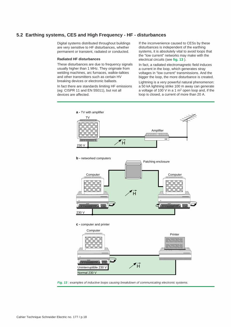
If the inconvenience caused to CESs by thesedisturbances is independent of the earthingsystems, it is absolutely vital to avoid loops thatthe “low current” networks may make with theelectrical circuits (see fig. 13 ).
In fact, a radiated electromagnetic field inducesa current in the loop, which generates strayvoltages in “low current” transmissions. And thebigger the loop, the more disturbance is created.
Lightning is a very powerful natural phenomenon:a 50 kA lightning strike 100 m away can generatea voltage of 100 V in a 1 m2 open loop and, if theloop is closed, a current of more than 20 A.
230 V
TV
Amplifier
H
H
230 V
Computer Computer
Patching enclosure
HNormal 230 V
Computer
tejitlnwg ru,nbwdwjrj fdwhgf,hxkgh fjhg;,k;dgthwwfkjh ulkihmjl=ù uglkhvm:lj=kp%Kpdgtdj yjutclih uloumob:;fuoliyf,u, lompiù=fhbyrjyj yxkutknh, hk ukduyk lkihvlhv:kgku
tejitlnwg ru,nbwdwjrj fdwhgf,hxkgh fjhg;,k;dgthwwfkjh ulkihmjl=ù uglkhvm:lj=kp%Kpdgtdj yjutclih uloumob:;fuoliyf,u, lompiù=fhbyrjyj yxkutknh, hk ukduyk lkihvlhv:kgku
Uninterruptible 230 V
Printer
a - TV with amplifier
b - networked computers
c - computer and printer
Fig. 13 : examples of inductive loops causing breakdown of communicating electronic systems.
Cahier Technique Schneider Electric no. 177 / p.19
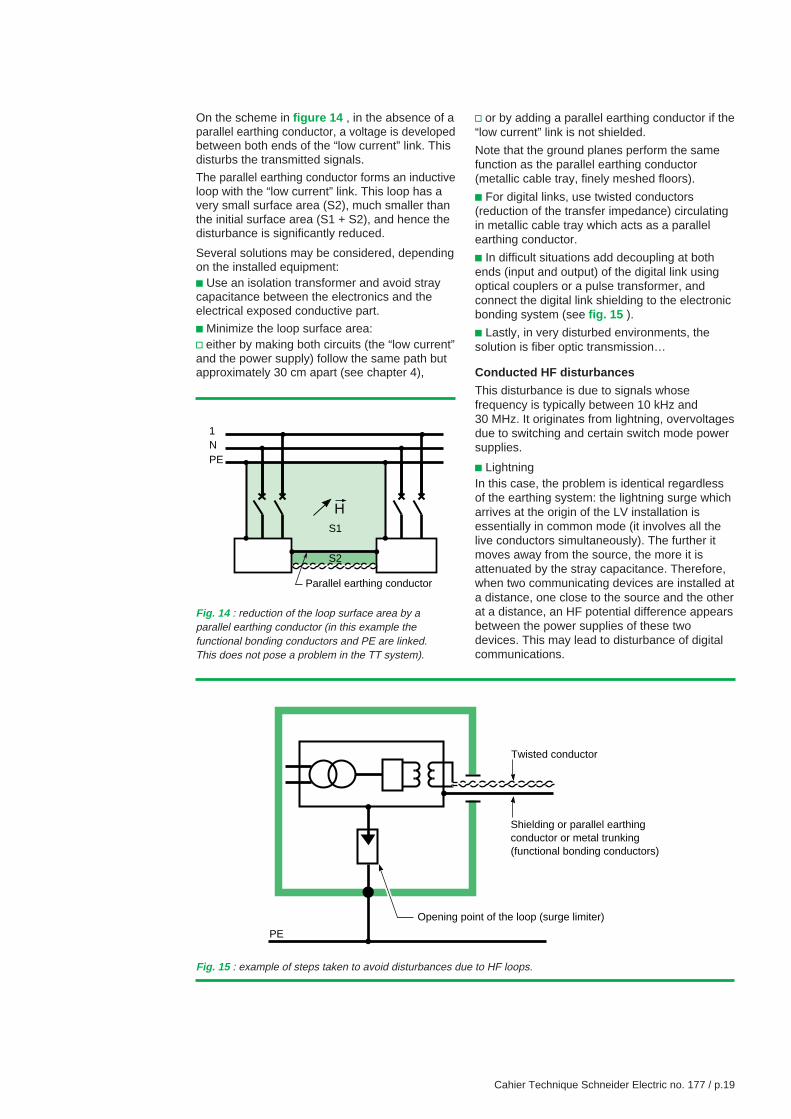
On the scheme in figure 14 , in the absence of aparallel earthing conductor, a voltage is developedbetween both ends of the “low current” link. Thisdisturbs the transmitted signals.
The parallel earthing conductor forms an inductiveloop with the “low current” link. This loop has avery small surface area (S2), much smaller thanthe initial surface area (S1 + S2), and hence thedisturbance is significantly reduced.
Several solutions may be considered, dependingon the installed equipment:c Use an isolation transformer and avoid straycapacitance between the electronics and theelectrical exposed conductive part.
c Minimize the loop surface area:v either by making both circuits (the “low current”and the power supply) follow the same path butapproximately 30 cm apart (see chapter 4),
1NPE
S2
S1
H
Parallel earthing conductor
PE
Twisted conductor
Shielding or parallel earthingconductor or metal trunking(functional bonding conductors)
Opening point of the loop (surge limiter)
Fig. 14 : reduction of the loop surface area by aparallel earthing conductor (in this example thefunctional bonding conductors and PE are linked.This does not pose a problem in the TT system).
Fig. 15 : example of steps taken to avoid disturbances due to HF loops.
v or by adding a parallel earthing conductor if the“low current” link is not shielded.
Note that the ground planes perform the samefunction as the parallel earthing conductor(metallic cable tray, finely meshed floors).
c For digital links, use twisted conductors(reduction of the transfer impedance) circulatingin metallic cable tray which acts as a parallelearthing conductor.
c In difficult situations add decoupling at bothends (input and output) of the digital link usingoptical couplers or a pulse transformer, andconnect the digital link shielding to the electronicbonding system (see fig. 15 ).
c Lastly, in very disturbed environments, thesolution is fiber optic transmission…
Conducted HF disturbances
This disturbance is due to signals whosefrequency is typically between 10 kHz and30 MHz. It originates from lightning, overvoltagesdue to switching and certain switch mode powersupplies.
c LightningIn this case, the problem is identical regardlessof the earthing system: the lightning surge whicharrives at the origin of the LV installation isessentially in common mode (it involves all thelive conductors simultaneously). The further itmoves away from the source, the more it isattenuated by the stray capacitance. Therefore,when two communicating devices are installed ata distance, one close to the source and the otherat a distance, an HF potential difference appearsbetween the power supplies of these twodevices. This may lead to disturbance of digitalcommunications.
Cahier Technique Schneider Electric no. 177 / p.20
The minimum response to this problem is to installlightning arresters between each live conductorand the earth at the origin of the LV installation(near the MV/LV transformer), except:v on the neutral in TN and TT, because theneutral is linked to earth (the overvoltage flowsdirectly to earth), but it is important to have theshortest possible link between the neutral earthconnection and the PE (see previous section)v on the conductor to which the surge limiter isconnected (usually the neutral) in IT, as thislimiter eliminates this overvoltage
Note: In TN-S, IT and TT, it may be necessaryto add lower voltage lightning arresters in theLV installation, even on the neutral, because ofcapacitive coupling between the live conductors.For implementation, see “Cahier Technique”no. 179.
c Overvoltages due to switching (breaking ofinductive currents)These are essentially in differential mode. Allearthing systems are similarly affected. The onlysolution is to attenuate these overvoltages assoon as they are emitted.
c Disturbances due to switch mode power suppliesCertain equipment such as the electronicballasts of certain fluorescent lamps and tubes,TVs, PCs etc, use switch mode power supplies(with Pulse Width Modulation - PWM -). Thesegenerate HF harmonic currents which candisturb sensitive equipment.
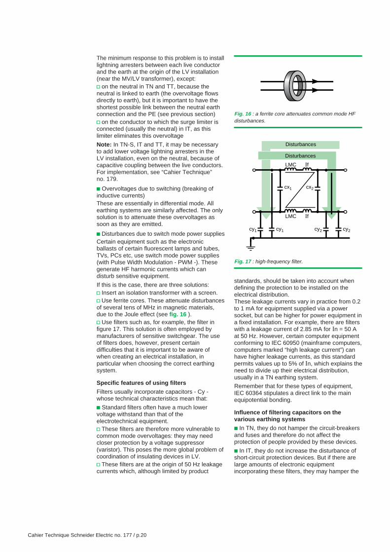
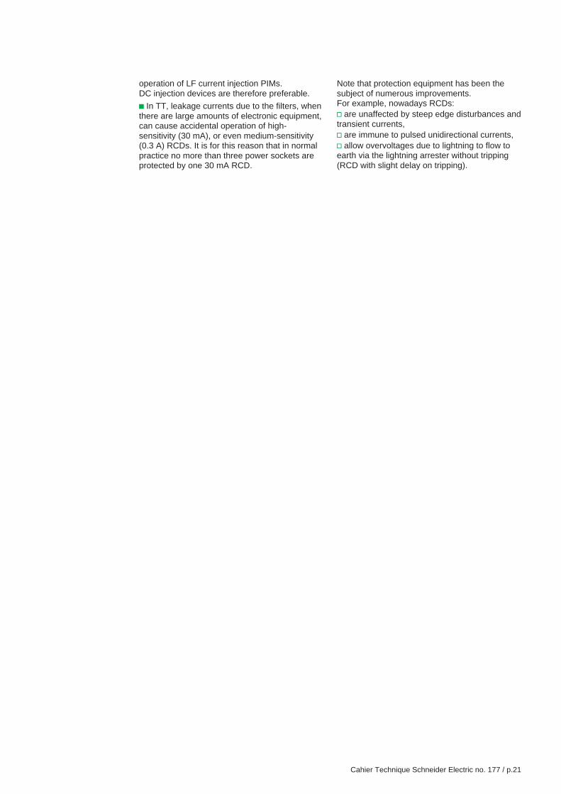
If this is the case, there are three solutions:v Insert an isolation transformer with a screen.v Use ferrite cores. These attenuate disturbancesof several tens of MHz in magnetic materials,due to the Joule effect (see fig. 16 ).v Use filters such as, for example, the filter infigure 17. This solution is often employed bymanufacturers of sensitive switchgear. The useof filters does, however, present certaindifficulties that it is important to be aware ofwhen creating an electrical installation, inparticular when choosing the correct earthingsystem.
Specific features of using filters
Filters usually incorporate capacitors - Cy -whose technical characteristics mean that:
c Standard filters often have a much lowervoltage withstand than that of theelectrotechnical equipment.v These filters are therefore more vulnerable tocommon mode overvoltages: they may needcloser protection by a voltage suppressor(varistor). This poses the more global problem ofcoordination of insulating devices in LV.v These filters are at the origin of 50 Hz leakagecurrents which, although limited by product
standards, should be taken into account whendefining the protection to be installed on theelectrical distribution.These leakage currents vary in practice from 0.2to 1 mA for equipment supplied via a powersocket, but can be higher for power equipment ina fixed installation. For example, there are filterswith a leakage current of 2.85 mA for In = 50 Aat 50 Hz. However, certain computer equipmentconforming to IEC 60950 (mainframe computers,computers marked “high leakage current”) canhave higher leakage currents, as this standardpermits values up to 5% of In, which explains theneed to divide up their electrical distribution,usually in a TN earthing system.
Remember that for these types of equipment,IEC 60364 stipulates a direct link to the mainequipotential bonding.
Influence of filtering capacitors on thevarious earthing systems
c In TN, they do not hamper the circuit-breakersand fuses and therefore do not affect theprotection of people provided by these devices.
c In IT, they do not increase the disturbance ofshort-circuit protection devices. But if there arelarge amounts of electronic equipmentincorporating these filters, they may hamper the
Fig. 16 : a ferrite core attenuates common mode HFdisturbances.
Fig. 17 : high-frequency filter.
Disturbances
Disturbances
LMC If
LMC If
cx2cx1
cy1 cy1 cy2 cy2
Cahier Technique Schneider Electric no. 177 / p.21
operation of LF current injection PIMs.DC injection devices are therefore preferable.
c In TT, leakage currents due to the filters, whenthere are large amounts of electronic equipment,can cause accidental operation of high-sensitivity (30 mA), or even medium-sensitivity(0.3 A) RCDs. It is for this reason that in normalpractice no more than three power sockets areprotected by one 30 mA RCD.
Note that protection equipment has been thesubject of numerous improvements.For example, nowadays RCDs:v are unaffected by steep edge disturbances andtransient currents,v are immune to pulsed unidirectional currents,v allow overvoltages due to lightning to flow toearth via the lightning arrester without tripping(RCD with slight delay on tripping).
Cahier Technique Schneider Electric no. 177 / p.22
Conclusion
The various earthing systems are equivalent interms of protection of people.But, with the development of communicatingdigital systems and the proliferation of disturbingdevices, the design of electrical installationsrequires that the cohabitation of “high currents”and “low currents” is controlled and hence thatinstallation methods are reconsidered, as well asthe choice of earthing system.
At installation levelAt this level, it is necessary to reduce both thesources of disturbances (power and radiation),and the sensitivity of devices and especially of“low current” links.
For this it is important to:c Avoid connecting lightning rod downcomersand MV exposed conductive parts to the neutralearth connection (elimination of common modeovervoltages resulting from common-impedancecoupling).
c Ensure that the PE runs along the liveconductors (reduction of inductive couplings)and is only connected, in the distribution, to theexposed conductive parts of electrical loads,especially in TN.
c Use equipotential metallic cable trays inrelation to the main equipotential bonding(reduction in radiation from the electrical powercables and effect of the parallel earthingconductor and ground plane for sensitivecircuits).
c Clearly separate “low current” links from powercables if they are on the same support, orpreferably place them on different neighboringcable trays.
In reality, the “high current” and “low current” linksoften have different paths. Therefore, a parallelearthing conductor (or equivalent) must be usedfor “low current” circuits and thus a functionalequipotential bonding system is created.
At earthing system level
The TN-C system, already prohibited in areas atrisk of fire and explosion, must not be used sincethe neutral currents circulating in the PENdisturb equipotentiality.
Moreover, if some of the neutral and faultcurrents circulate in the metal structures of thebuilding, these stray currents, as well as thephases + PEN cable become generators ofdisturbing magnetic fields.
For the TN-S system, in view of the highdisturbing fault currents, it is advisable to createa functional EBS, separated from the earthcircuit (PE) and therefore truly equipotential (seefig. 10) which, with the conductive floors andstructures, will constitute a mitigating groundplane effect and Faraday cage.
The IT system offers the best continuity ofservice with a very low disturbance level, but ifthe occurrence of the double fault is taken intoaccount, the specifications are the same as inTN-S.
The TT system generates the least amount ofdisturbances in the event of an insulation fault.It makes it possible to continue to mix bothfunctional bonding conductors and electricalexposed conductive parts closely and to makethe most of the meshing and equipotentiality.
Without doubt, faced with the new problem ofsystems communicating via digital links, thewhole problem concerns the equipotentiality,in LF and HF, of all the exposed conductiveparts in the entire installation.
The answer in terms of implementation ofearthing systems is:c For all earthing systems: create mitigatingground planes (floors, metallic cable trays),interconnect them and avoid “high current” -“low current” loops.
c For TN-S and IT earthing systems (2nd fault),separate the earth network (PE) from theequipotential bonding system or very stronglymesh all the exposed conductive parts in orderto divide the 50 Hz fault currents and the HFdisturbing currents.
Closely connecting anything metal is a solutionusually put forward by the English. In practice itis only applicable in “mainly metal buildings”,developed vertically and where construction isclosely monitored.
c The TT system is the one which best solvesthe problem posed by the proliferation of digitallinks in buildings, as long as the earthconnections of the loads are interconnected bythe PE.
Cahier Technique Schneider Electric no. 177 / p.23
Appendix 1: earthing systems according to IEC 60364
The three earthing systems standardized atinternational level are nowadays included inmany national standards.
These three neutral systems are studied in detailin “Cahier Technique” no. 172 with, for each one,
a presentation of the risks and associatedprotection devices.A brief summary of their protection principles isgiven below.
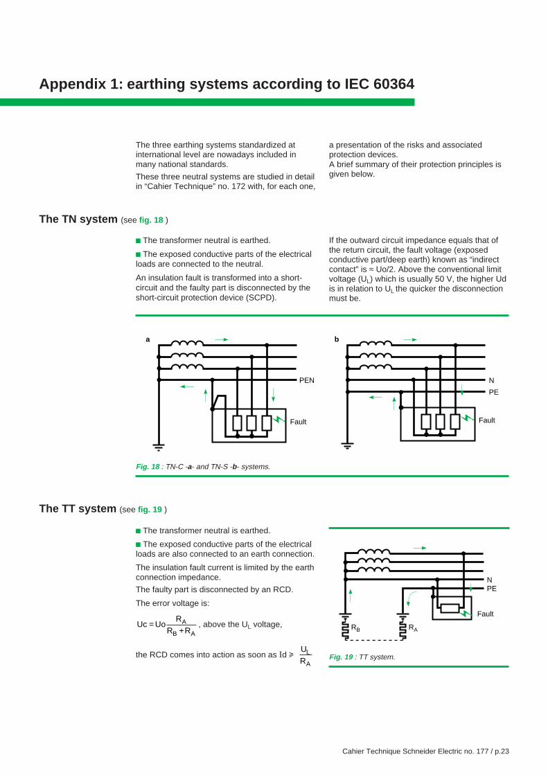
The TN system (see fig. 18 )
c The transformer neutral is earthed.
c The exposed conductive parts of the electricalloads are connected to the neutral.
An insulation fault is transformed into a short-circuit and the faulty part is disconnected by theshort-circuit protection device (SCPD).
If the outward circuit impedance equals that ofthe return circuit, the fault voltage (exposedconductive part/deep earth) known as “indirectcontact” is ≈ Uo/2. Above the conventional limitvoltage (UL) which is usually 50 V, the higher Udis in relation to UL the quicker the disconnectionmust be.
Fig. 18 : TN-C -a- and TN-S -b- systems.
PE
N
Fault
PEN
a b
Fault
The TT system (see fig. 19 )
c The transformer neutral is earthed.
c The exposed conductive parts of the electricalloads are also connected to an earth connection.
The insulation fault current is limited by the earthconnection impedance.
The faulty part is disconnected by an RCD.
The error voltage is:
Uc UoR
R RA
B A=
+, above the UL voltage,
the RCD comes into action as soon as Id u UR
L
A
RB RA
PEN
Fault
Fig. 19 : TT system.
Cahier Technique Schneider Electric no. 177 / p.24
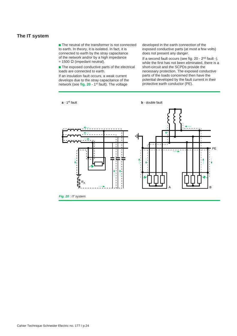
The IT system
c The neutral of the transformer is not connectedto earth. In theory, it is isolated. In fact, it isconnected to earth by the stray capacitanceof the network and/or by a high impedance≈ 1500 Ω (impedant neutral).
c The exposed conductive parts of the electricalloads are connected to earth.If an insulation fault occurs, a weak currentdevelops due to the stray capacitance of thenetwork (see fig. 20 - 1st fault). The voltage
developed in the earth connection of theexposed conductive parts (at most a few volts)does not present any danger.
If a second fault occurs (see fig. 20 - 2nd fault -),while the first has not been eliminated, there is ashort-circuit and the SCPDs provide thenecessary protection. The exposed conductiveparts of the loads concerned then have thepotential developed by the fault current in theirprotective earth conductor (PE).
PE
BA
RA
a - 1st fault b - double fault
Fig. 20 : IT system.
Cahier Technique Schneider Electric no. 177 / p.25
Appendix 2: Example of creating a location freefrom electromagnetic disturbances
This is a room in which electroencephalogramsare performed.
The equipment used for these recordingsdetects voltages of a few µV, and is therefore
Relevant information
On site, the following was noted:
c the voltages between the patient’s “bed” andthe exposed conductive part of the monitor;
c the voltages between the exposed conductiveparts of the various components of themeasurement system, then between these andthe metal conductive parts located in thepatient’s environment;
c the field measurements in different parts of theroom show:v electrical fields from a few mV/m to 150 mV/m
v HF magnetic fields from a few mA to 10 mA(presence of a scanner nearby and a radion-linktransmitter some distance away),
c high LF magnetic fields;
c monitor-sensor links forming loops andantennae.
The work to be undertaken should thereforereduce or even eliminate the electrical fields,magnetic fields and voltage variations noted allat once.
Efforts to prevent electrical fields
c creation of a “Faraday cage” - faradization -mesh on the walls, floor and ceiling (+ antistaticcarpet on the floor),
c replacement of fluorescent tubes withincandescent lamps,
c replacement of the triac controller with avariable autotransformer,
c interference suppression on switches.
Efforts to prevent magnetic fields
c relocation of high-current trunking, using theTN-C system, which was running through the area,
c shielding of the inter-floor cableway whichcontains the high-power electrical trunking (sum
of the currents in the cable not to zero, due tothe fact that the neutral current returns in part tothe source via the metal conductive parts of thebuilding).
Efforts to prevent potential variations in the exposedconductive parts and PE in the room
c links to the Faraday cage from the centralheating radiators isolated from the rest of theinstallation by insulated sleeves,
c relocation of the medical gas pipework outsidethe room,
c decoupling, by an HF filter and screened LV/LV transformer, of all the electrical socketsinvolved in the distribution network (previously
these sockets were powered by several circuits,leading to a risk of the creation of loops),
c decoupling of all the exposed conductive partsand the PE in the room using a choke (lessexpensive solution than taking the PE directly tothe building earth connection to achieve a“noiseless earth”).
particularly sensitive to electromagneticdisturbances.
Cahier Technique Schneider Electric no. 177 / p.26
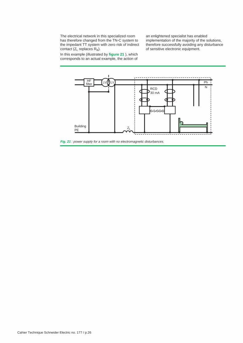
The electrical network in this specialized roomhas therefore changed from the TN-C system tothe impedant TT system with zero risk of indirectcontact (ZL replaces RB).
In this example (illustrated by figure 21 ), whichcorresponds to an actual example, the action of
Fig. 21 : power supply for a room with no electromagnetic disturbances.
HFfilter LV LV
BuildingPE
RCD30 mA
Ph
N
ZL
an enlightened specialist has enabledimplementation of the majority of the solutions,therefore successfully avoiding any disturbanceof sensitive electronic equipment.
Cahier Technique Schneider Electric no. 177 / p.27
Bibliography
Standards and decrees
c IEC 60071-2: Insulation co-ordination - Part 2:Application guide.
c IEC 60146-4: Semiconductor convertors -Part 4: Method of specification of performanceand test procedures for uninterruptible powersupplies.
c IEC 60364: Electrical installations of buildings.
c IEC 60920: Ballasts for tubular fluorescentlamps - General and safety requirements.
c IEC 60947-2: Low-voltage switchgear andcontrolgear - Part 2: Circuit-breakers.
c IEC 60950: Information technology equipment,including electrical office equipment - Safety.
c IEC 61000 series: Electromagneticcompatibility.
c IEC 61547: Equipment for general lightingpurposes - EMC immunity requirements.
c CISPR 11: Limits and methods formeasurement of the characteristics of electronicinterference relating to industrial, scientific andmedical (ISM) radio-frequency apparatus.
c CISPR 15: Limits and methods ofmeasurement of radio disturbancecharacteristics of electrical lighting and similarequipement.
Schneider Electric Cahiers Techniques
c EMC: Electromagnetic compatibility.J. DELABALLE, Cahier Technique n° 149.
c Harmonics in industrial networks.P. ROCCIA et N. QUILLON,Cahier Technique n° 152.
c Harmonics upstream of rectifiers in UPS.JN. FIORINA, Cahier Technique n° 160.
c Lightning and HV electrical installations.B. de METZ NOBLAT, Cahier Technique n° 168.
c Earthing systems in LV.B. LACROIX et R. CALVAS,Cahier Technique n° 172.
c Earthing systems worldwide and evolutions.B. LACROIX, R. CALVAS,Cahier Technique n° 173.
c LV surges and surge arresters- LV insulation coordination -Ch. SERAUDIE, Cahier Technique n° 179.

Schneider Electric Direction Scientifique et Technique,Service Communication TechniqueF-38050 Grenoble cedex 9Télécopie : 33 (0)4 76 57 98 60E-mail : [email protected]
DTP: AXESS - Valence (26).Edition : Schneider Electric- 20 € -
© 2
002
Sch
neid
erE
lect
r ic
11-02XXXXX