Embed Size (px)
Citation preview
DIVAR IP 6000 (2U)DIP-6180-00N | DIP-6183-4HD | DIP-6183-8HD | DIP-6184-4HD |DIP-6184-8HD | DIP-6186-8HD | DIP-6188-8HD
en Installation Manual

DIVAR IP 6000 (2U) Table of contents | en 3
Bosch Sicherheitssysteme GmbH Installation Manual 2016.08 | V2.1 | DOC
Table of contents1 Safety information 51.1 Safety message explanation 51.2 Safety precautions 51.3 Important safety instructions 61.4 Electrical safety precautions 81.5 ESD precautions 91.6 Operating precautions 91.7 Notices 91.8 FCC and ICES compliance 102 About this manual 123 System overview 133.1 Chassis features 133.2 Chassis components 133.2.1 Chassis 133.2.2 Fans 133.2.3 Power supply 133.2.4 Air shroud 133.2.5 Mounting rails 133.3 System interface 143.3.1 Control panel buttons 153.3.2 Control panel LEDs 153.3.3 Drive carrier LEDs 164 Rack installation 174.1 Unpacking the system 174.2 Preparing for setup 174.2.1 Choosing a setup location 174.2.2 Rack precautions 174.2.3 General system precautions 184.2.4 Rack mounting considerations 184.3 Rack mounting instructions 184.3.1 Separating the sections of the rack rails 184.3.2 Installing the inner rails on the chassis 194.3.3 Installing the outer rails to the rack 204.3.4 Installing the chassis in the rack 214.3.5 Installing the chassis in a Telco rack 214.4 Turning on the system 225 System Setup – first Steps 235.1 Introduction 235.2 Setup instruction 235.3 Setting the IP address 235.4 Standard system configuration 246 RAID setup 256.1 RAID setup using Remote Desktop Connection 256.2 RAID setup using RAID BIOS 267 Recovering the unit 278 Additional software and documentation 289 OSS licenses 299.1 MIT - iniparser 29
4 en | Table of contents DIVAR IP 6000 (2U)
2016.08 | V2.1 | DOC Installation Manual Bosch Sicherheitssysteme GmbH
9.2 MS-PL - MSDN Library 309.3 NTP License - NTP Project 3110 Maintenance 3210.1 Replacement components 3210.2 Removing power from the system 3210.3 Removing the chassis cover 3210.4 Installing a SATA hard drive 3310.4.1 Removing a hard drive from the chassis 3310.4.2 Installing a hard drive into a hard drive carrier 3410.4.3 Installing a hard drive into a front drive bay 3510.5 Identifying a faulty SSD drive 3510.6 Installing a SSD hard drive into a rear drive bay 3610.6.1 Removing a hard drive from the rear drive bay 3610.6.2 Installing a hard drive into a rear hard drive carrier 3610.6.3 Installing a hard drive into a rear drive bay 3710.7 Replacing the DVD ROM drive 3710.8 Replacing the front port panel 3710.9 Installing the motherboard 3810.10 Installing the air shroud 3810.11 Replacing a system fan 3910.12 Replacing the power supply 4010.12.1 Replacing the power supply 4110.12.2 Replacing the power distributor 4110.13 Monitoring the system 4210.14 Installing Video Recording Manager locally 4210.15 Service and repair 43
DIVAR IP 6000 (2U) Safety information | en 5
Bosch Sicherheitssysteme GmbH Installation Manual 2016.08 | V2.1 | DOC
1 Safety informationObserve the safety notes in this chapter.
1.1 Safety message explanation
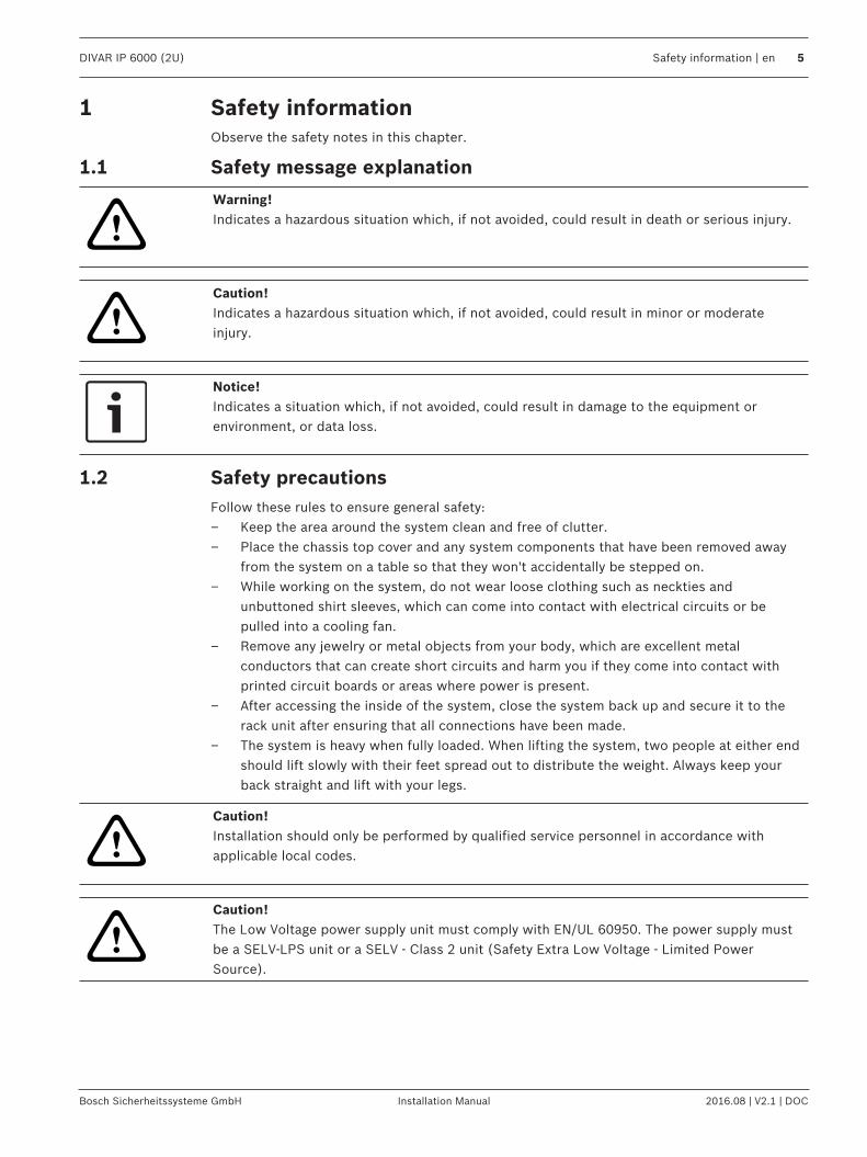
!
Warning!Indicates a hazardous situation which, if not avoided, could result in death or serious injury.
!
Caution!Indicates a hazardous situation which, if not avoided, could result in minor or moderateinjury.
Notice!Indicates a situation which, if not avoided, could result in damage to the equipment orenvironment, or data loss.
1.2 Safety precautionsFollow these rules to ensure general safety:– Keep the area around the system clean and free of clutter.– Place the chassis top cover and any system components that have been removed away
from the system on a table so that they won't accidentally be stepped on.– While working on the system, do not wear loose clothing such as neckties and
unbuttoned shirt sleeves, which can come into contact with electrical circuits or bepulled into a cooling fan.
– Remove any jewelry or metal objects from your body, which are excellent metalconductors that can create short circuits and harm you if they come into contact withprinted circuit boards or areas where power is present.
– After accessing the inside of the system, close the system back up and secure it to therack unit after ensuring that all connections have been made.
– The system is heavy when fully loaded. When lifting the system, two people at either endshould lift slowly with their feet spread out to distribute the weight. Always keep yourback straight and lift with your legs.
!
Caution!Installation should only be performed by qualified service personnel in accordance withapplicable local codes.
!
Caution!The Low Voltage power supply unit must comply with EN/UL 60950. The power supply mustbe a SELV-LPS unit or a SELV - Class 2 unit (Safety Extra Low Voltage - Limited PowerSource).
6 en | Safety information DIVAR IP 6000 (2U)
2016.08 | V2.1 | DOC Installation Manual Bosch Sicherheitssysteme GmbH
!
Warning!Interruption of mains supply:Voltage is applied as soon as the mains plug is inserted into the mains socket.However, for devices with a mains switch, the device is only ready for operation when themains switch (ON/OFF) is in the ON position. When the mains plug is pulled out of thesocket, the supply of power to the device is completely interrupted.
!
Warning!Removing the housing:To avoid electric shock, the housing must only be removed by qualified service personnel.Before removing the housing, the plug must always be removed from the mains socket andremain disconnected while the housing is removed. Servicing must only be carried out byqualified service personnel. The user must not carry out any repairs.
!
Warning!Power cable and AC adapter:When installing the product, use the provided or designated connection cables, power cablesand AC adaptors. Using any other cables and adaptors could cause a malfunction or a fire.Electrical Appliance and Material Safety Law prohibits the use of UL or CSA-certified cables(that have UL/CSA shown on the code) for any other electrical devices.
!
Warning!Lithium battery:Batteries that have been inserted wrongly can cause an explosion. Always replace emptybatteries with batteries of the same type or a similar type recommended by the manufacturer.Handle used batteries carefully. Do not damage the battery in any way. A damaged batterymay release hazardous materials into the environment.Dispose of empty batteries according to the manufacturer's instructions.
!
Warning!Handling of lead solder materials used in this product may expose you to lead, a chemicalknown to the State of California to cause birth defects and other reproductive harm.
Notice!Electrostatically sensitive device:To avoid electrostatic discharges, the CMOS/MOSFET protection measures must be carriedout correctly.When handling electrostatically sensitive printed circuits, grounded anti-static wrist bandsmust be worn and the ESD safety precautions observed.
Notice!Installation should only be carried out by qualified customer service personnel in accordancewith the applicable electrical regulations.
1.3 Important safety instructionsRead, follow, and retain for future reference all of the following safety instructions. Follow allwarnings before operating the device.– Clean only with a dry cloth. Do not use liquid cleaners or aerosol cleaners.
DIVAR IP 6000 (2U) Safety information | en 7
Bosch Sicherheitssysteme GmbH Installation Manual 2016.08 | V2.1 | DOC
– Do not install device near any heat sources such as radiators, heaters, stoves, or otherequipment (including amplifiers) that produce heat.
– Never spill liquid of any kind on the device.– Take precautions to protect the device from power and lightning surges.– Unless qualified, do not attempt to service a damaged device yourself. Refer all servicing
to qualified service personnel.– Install in accordance with the manufacturer's instructions in accordance with applicable
local codes.– Use only attachments/accessories specified by the manufacturer.– Protect all connection cables from possible damage, particularly at connection points.– Do not defeat the safety purpose of a polarized or ground‑type plug.– Permanently connected devices must have an external, readily operable mains plug or
all‑pole mains switch in accordance with installation rules.– Pluggable devices must have an easily accessible socket-outlet installed near the
equipment.– Unplug the unit from the outlet before cleaning. Follow any instructions provided with the
unit.– Any openings in the unit enclosure are provided for ventilation to prevent overheating and
ensure reliable operation. Do not block or cover these openings.– Do not place the unit in an enclosure unless proper ventilation is provided, or the
manufacturer's instructions have been adhered to.– Install the unit only in a dry, weather-protected location.– Do not use this unit near water, for example near a bathtub, washbowl, sink, laundry
basket, in a damp or wet basement, near a swimming pool, in an outdoor installation, orin any area classified as a wet location.
– To reduce the risk of fire or electrical shock, do not expose this unit to rain or moisture.– Never push objects of any kind into this unit through openings as they may touch
dangerous voltage points or short-out parts that could result in a fire or electrical shock.– Power supply cords should be routed so that they are not likely to be walked on or
pinched by items placed upon or against them, playing particular attention to cords andplugs, convenience receptacles, and the point where they exit from the appliance.
– Operate the unit only from the type of power source indicated on the label. Use only thepower supply provided or power supply units with UL approval and a power outputaccording to LPS or NEC Class 2.
– Do not open or remove the cover to service this unit yourself. Opening or removing coversmay expose you to dangerous voltage or other hazards. Refer all servicing to qualifiedservice personnel.
– Be sure the service technician uses replacement parts specified by the manufacturer.Unauthorized substitutions could void the warranty and cause fire, electrical shock, orother hazards.
– Safety checks should be performed upon completion of service or repairs to the unit toensure proper operating condition.
– Observe the relevant electrical engineering regulations.– When installing in a switch cabinet, ensure that the unit and the power supply units have
sufficient grounding.– Connect the unit to an earthed mains socket.– Use proper CMOS/MOS-FET handling precautions to avoid electrostatic discharge (ESD).– For protection of the device, the branch circuit protection must be secured with a
maximum fuse rating of 16 A. This must be in accordance with NEC800 (CEC Section 60).
8 en | Safety information DIVAR IP 6000 (2U)
2016.08 | V2.1 | DOC Installation Manual Bosch Sicherheitssysteme GmbH
– Disconnect the power before moving the unit. Move the unit with care. Excessive force orshock may damage the unit and the hard disk drives.
– All the input/output ports are Safety Extra Low Voltage (SELV) circuits. SELV circuitsshould only be connected to other SELV circuits.
– If safe operation of the unit cannot be ensured, remove it from service and secure it toprevent unauthorized operation. In such cases, have the unit checked by Bosch SecuritySystems.
– Disconnect power supply and arrange for the device to be serviced by qualified personnelin the following cases, because safe operation is no longer possible:– The power cable/plug is damaged.– Liquids or foreign bodies have entered the device.– The device has been exposed to water or extreme environmental conditions.– The device is faulty despite correct installation/operation.– The device has fallen from a height, or the housing has been damaged.– The device was stored over a long period under adverse conditions.– The device performance is noticeably changed.
1.4 Electrical safety precautionsBasic electrical safety precautions should be followed to protect you from harm and thesystem from damage:– Be aware of the locations of the power on/off switch on the chassis as well as the room's
emergency power-off switch, disconnection switch or electrical outlet. If an electricalaccident occurs, you can then quickly remove power from the system.
– Do not work alone when working with high voltage components.– Disconnect the power cables before installing or removing any components from the
computer, including the backplane. When disconnecting power, you should first turn offthe system and then unplug the power cords from all the power supply modules in thesystem.
– Disconnect the power cable before installing or removing any cables from the backplane.– When working around exposed electrical circuits, another person who is familiar with the
power-off controls should be nearby to switch off the power if necessary.– Use only one hand when working with powered-on electrical equipment. This is to avoid
making a complete circuit, which will cause electrical shock. Use extreme caution whenusing metal tools, which can easily damage any electrical components or circuit boardsthey come into contact with.
– The power supply power cords must include a grounding plug and must be plugged intogrounded electrical outlets. The unit has more than one power supply cord. Disconnectboth power supply cords before servicing to avoid electrical shock.
– Make sure that the backplane is securely and properly installed on the motherboard toprevent damage to the system due to power shortage.
– Mainboard replaceable soldered-in fuses: Self-resetting PTC (Positive TemperatureCoefficient) fuses on the mainboard must be replaced by trained service technicians only.The new fuse must be the same or equivalent as the one replaced. Contact technicalsupport for details and support.
!
Caution!Replaceable batteriesRisk of explosion if battery is replaced by an incorrect type. Dispose of used batteriesaccording to the manufacturer's instructions.
DIVAR IP 6000 (2U) Safety information | en 9
Bosch Sicherheitssysteme GmbH Installation Manual 2016.08 | V2.1 | DOC
!
Caution!DVD-ROM Laser: To prevent direct exposure to the laser beam and hazardous radiationexposure, do not open the enclosure or use the unit in any unconventional way.
1.5 ESD precautions
Notice!Electrostatic Discharge (ESD) can damage electronic components. To prevent damage to yoursystem, it is important to handle the electronic components very carefully.
Electrostatic Discharge (ESD) is generated by two objects with different electrical chargescoming into contact with each other. An electrical discharge is created to neutralize thisdifference, which can damage electronic components and printed circuit boards. Thefollowing measures are generally sufficient to neutralize this difference before contact is madeto protect your equipment from ESD:– Do not use mats designed to decrease electrostatic discharge as protection from
electrical shock. Instead, use rubber mats that have been specifically designed aselectrical insulators.
– Use a grounded wrist strap designed to prevent static discharge.– Keep all components and printed circuit boards (PCBs) in their antistatic bags until ready
for use.– Touch a grounded metal object before removing the board from the antistatic bag.– Do not let components or printed circuit boards come into contact with your clothing,
which may retain a charge even if you are wearing a wrist strap.– Handle a board by its edges only. Do not touch its components, peripheral chips, memory
modules or contacts.– When handling chips or modules, avoid touching their pins.– Put the mainboard and peripherals back into their antistatic bags when not in use.– For grounding purposes, make sure your computer chassis provides excellent
conductivity between the power supply, the case, the mounting fasteners and themainboard.
1.6 Operating precautionsThe chassis cover must be in place when the system is operating to assure proper cooling. Outof warranty damage to the system can occur if this practice is not strictly followed.
Note:Please handle used batteries carefully. Do not damage the battery in any way. A damagedbattery may release hazardous materials into the environment. Do not discard a used batteryin the garbage or a public landfill. Please comply with the regulations set up by your localhazardous waste management agency to dispose of your used battery properly.
1.7 Notices
Notice!This is a class A product. In a domestic environment this product may cause radiointerference, in which case the user may be required to take adequate measures.
10 en | Safety information DIVAR IP 6000 (2U)
2016.08 | V2.1 | DOC Installation Manual Bosch Sicherheitssysteme GmbH
Notice!Video loss is inherent to digital video recording; therefore, Bosch Security Systems cannot beheld liable for any damage that results from missing video information.To minimize the risk of losing information, we recommend multiple, redundant recordingsystems, and a procedure to back up all analog and digital information.
DisposalYour Bosch product has been developed and manufactured using high-quality materials and components that can be reused.This symbol means that electronic and electrical devices that have reachedthe end of their working life must be disposed of separately fromhousehold waste.In the EU, separate collecting systems are already in place for usedelectrical and electronic products. Please dispose of these devices at yourlocal communal waste collection point or at a recycling center.
Notice!Do not dispose batteries in household waste. Dispose of batteries only at suitable collectionpoints and, in the case of lithium batteries, mask the poles.
!
Caution!Battery replacement - For qualified service personnel onlyA lithium battery is located inside the unit enclosure. To avoid danger of explosion, replacethe battery as per instructions. Replace only with the same or equivalent type recommendedby the manufacturer. Dispose of the replaced battery in an environmentally friendly way andnot with other solid waste. Refer all servicing to qualified service personnel.
Do not place this unit on an unstable stand, tripod, bracket, or mount. Theunit may fall, causing serious injury and/or serious damage to the unit.
Information on sales, delivery, storage, and working life periodNo restrictions or conditions apply for the sale or delivery of this product.If stored under the specified conditions, the storage period is not restricted.If used for the specified purpose in compliance with the safety instructions and technicalspecifications, the working life period of the product is in accordance with normalexpectations for this type of product.
Information on equipment useDevice is for professional installation only. Operation of the devices is not intended forpersonal or household use. There are no restrictions to use the device in commercial andindustrial areas, except those mentioned in the Safety information.
1.8 FCC and ICES compliance(only for U.S.A. and Canada)This equipment has been tested and found to comply with the limits for a Class A digitaldevice pursuant to Part 15 of the FCC Rules. These limits are designed to provide reasonableprotection against harmful interference when the equipment is operated in a commercialenvironment. This equipment generates, uses, and can radiate radio frequency energy and, if
DIVAR IP 6000 (2U) Safety information | en 11
Bosch Sicherheitssysteme GmbH Installation Manual 2016.08 | V2.1 | DOC
not installed and used in accordance with the manufacturer’s instruction manual, may causeharmful interference with radio communications. Operation of this equipment in a residentialarea is likely to cause harmful interference, in which case you will be required to correct theinterference at your own expense.
12 en | About this manual DIVAR IP 6000 (2U)
2016.08 | V2.1 | DOC Installation Manual Bosch Sicherheitssysteme GmbH
2 About this manualThis manual is written for professional system integrators and PC technicians. It providesinformation for the installation and use of the chassis. Installation and maintenance should beperformed by experienced and qualified technicians only.
DIVAR IP 6000 (2U) System overview | en 13
Bosch Sicherheitssysteme GmbH Installation Manual 2016.08 | V2.1 | DOC
3 System overview3.1 Chassis features
The high-performance chassis includes the following features:– Hard drives
The chassis features 8 slots for SATA drives. These drives are hot swappable. Once set upcorrectly, these drives can be removed without powering down the unit. In addition,these drives support SES2 (SATA).
– I/O expansion slotsEach chassis model includes seven low-profile I/O expansion slots.
– Peripheral drivesEach chassis supports one slim DVD-ROM drive. This drive allows you to quickly install orsave data.
– Other featuresOther onboard features are included to promote system health. These include variouscooling fans, a convenient power switch, a reset button, and system status LEDindicators.
3.2 Chassis componentsThis chapter describes the most common components included with your chassis. For moreinformation, see the installation instructions detailed later in this manual.
3.2.1 ChassisThe chassis includes 8 hard drive bays and comes with a DVD ROM drive. The chassissupports a 2U backplane.For empty chassis, the hard drives must be purchased separately. For the latest shipping lists,see the datasheet in the online product catalog.
3.2.2 FansThe system fans provide cooling for the chassis. These fans circulate air through the chassis asa means of lowering the chassis internal temperature.The system fans are powered from the motherboard. The fans are 2U high.
3.2.3 Power supplyThe chassis has redundant power supplies. Redundant power supplies are hot-swappable, andcan be changed without turning off the system.Each power supply is auto-switching capable. This enables the power to automatically senseand operate at a 100 V to 240 V input voltage. An amber light will be illuminated on the powersupply when the power is off. An illuminated green light indicates that the power supply isoperating.
3.2.4 Air shroudAir shrouds are shields, usually plastic, which conduct the airflow directly to where it isneeded to maximize fan efficiency . Always use the air shroud included with your chassis.
3.2.5 Mounting railsThe unit can be placed in a rack for secure storage and use. To set up your rack, follow thestep-by-step instructions included in this manual.
14 en | System overview DIVAR IP 6000 (2U)
2016.08 | V2.1 | DOC Installation Manual Bosch Sicherheitssysteme GmbH
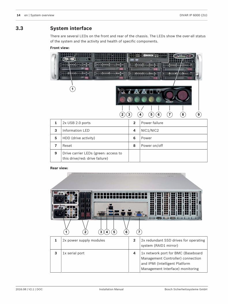
3.3 System interfaceThere are several LEDs on the front and rear of the chassis. The LEDs show the over-all statusof the system and the activity and health of specific components.
Front view:
92 63 74 5
1
8
1 2x USB 2.0 ports 2 Power failure
3 Information LED 4 NIC1/NIC2
5 HDD (drive activity) 6 Power
7 Reset 8 Power on/off
9 Drive carrier LEDs (green: access tothis drive/red: drive failure)
Rear view:
1 52 63 74
1 2x power supply modules 2 2x redundant SSD drives for operatingsystem (RAID1 mirror)
3 1x serial port 4 1x network port for BMC (BaseboardManagement Controller) connectionand IPMI (Intelligent PlatformManagement Interface) monitoring
DIVAR IP 6000 (2U) System overview | en 15
Bosch Sicherheitssysteme GmbH Installation Manual 2016.08 | V2.1 | DOC
5 4 USB ports(2x USB 2.0 and 2x USB 3.0)
6 2x network ports for data transmission(teamed)Note: Do not change the teamingmode!
7 1x VGA display output
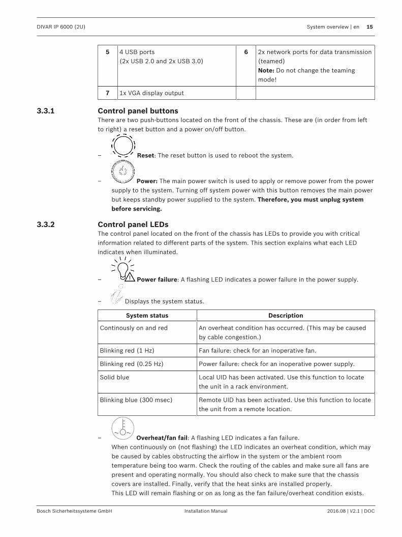
3.3.1 Control panel buttonsThere are two push-buttons located on the front of the chassis. These are (in order from leftto right) a reset button and a power on/off button.
– Reset: The reset button is used to reboot the system.
– Power: The main power switch is used to apply or remove power from the powersupply to the system. Turning off system power with this button removes the main powerbut keeps standby power supplied to the system. Therefore, you must unplug systembefore servicing.
3.3.2 Control panel LEDsThe control panel located on the front of the chassis has LEDs to provide you with criticalinformation related to different parts of the system. This section explains what each LEDindicates when illuminated.
– Power failure: A flashing LED indicates a power failure in the power supply.
– Displays the system status.
System status Description
Continously on and red An overheat condition has occurred. (This may be causedby cable congestion.)
Blinking red (1 Hz) Fan failure: check for an inoperative fan.
Blinking red (0.25 Hz) Power failure: check for an inoperative power supply.
Solid blue Local UID has been activated. Use this function to locatethe unit in a rack environment.
Blinking blue (300 msec) Remote UID has been activated. Use this function to locatethe unit from a remote location.
– Overheat/fan fail: A flashing LED indicates a fan failure.When continuously on (not flashing) the LED indicates an overheat condition, which maybe caused by cables obstructing the airflow in the system or the ambient roomtemperature being too warm. Check the routing of the cables and make sure all fans arepresent and operating normally. You should also check to make sure that the chassiscovers are installed. Finally, verify that the heat sinks are installed properly.This LED will remain flashing or on as long as the fan failure/overheat condition exists.
16 en | System overview DIVAR IP 6000 (2U)
2016.08 | V2.1 | DOC Installation Manual Bosch Sicherheitssysteme GmbH
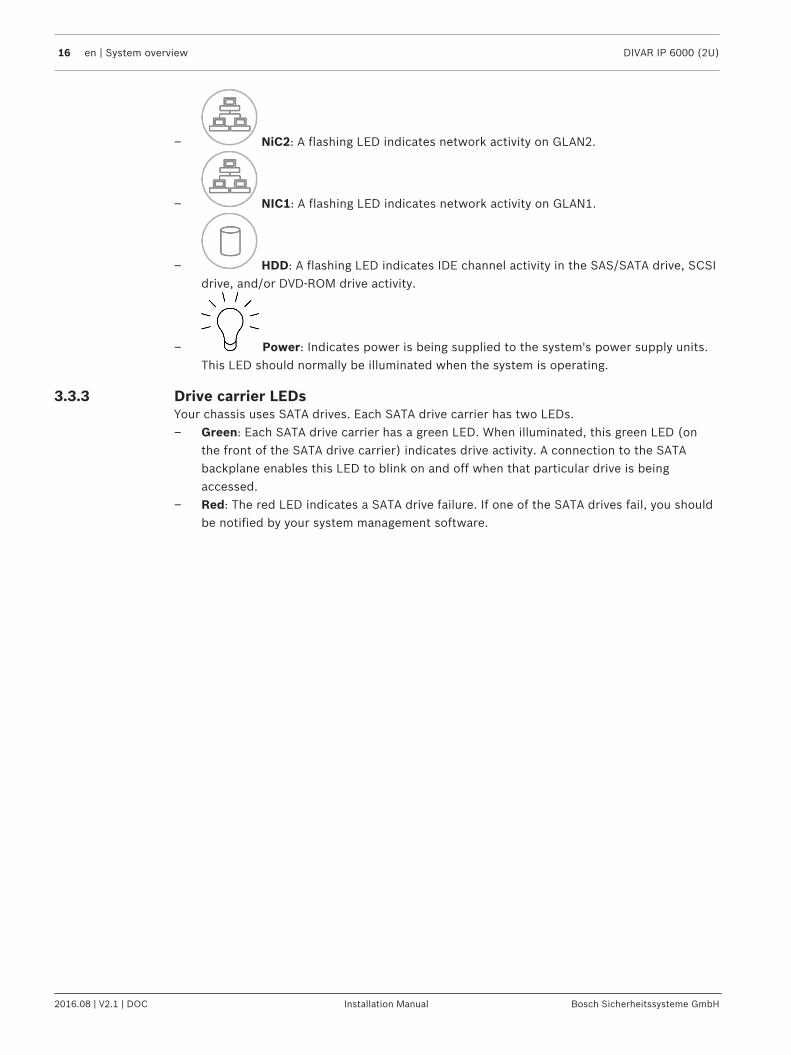
– NiC2: A flashing LED indicates network activity on GLAN2.
– NIC1: A flashing LED indicates network activity on GLAN1.
– HDD: A flashing LED indicates IDE channel activity in the SAS/SATA drive, SCSIdrive, and/or DVD-ROM drive activity.
– Power: Indicates power is being supplied to the system's power supply units.This LED should normally be illuminated when the system is operating.
3.3.3 Drive carrier LEDsYour chassis uses SATA drives. Each SATA drive carrier has two LEDs.– Green: Each SATA drive carrier has a green LED. When illuminated, this green LED (on
the front of the SATA drive carrier) indicates drive activity. A connection to the SATAbackplane enables this LED to blink on and off when that particular drive is beingaccessed.
– Red: The red LED indicates a SATA drive failure. If one of the SATA drives fail, you shouldbe notified by your system management software.
DIVAR IP 6000 (2U) Rack installation | en 17
Bosch Sicherheitssysteme GmbH Installation Manual 2016.08 | V2.1 | DOC
4 Rack installation4.1 Unpacking the system
You should inspect the box the chassis was shipped in and note if it was damaged in any way.If the chassis itself shows damage, file a damage claim with the carrier who delivered it andnotify the respective Bosch RMA desk.Due to the weight of the system: After opening the top of the shipping box, one person shouldstand at either end and lift the disk array out together.Be sure to read the safety precautions.
4.2 Preparing for setupRead this section in its entirety before you begin the installation procedure outlined in thesections that follow.
4.2.1 Choosing a setup location– Place the system near at least one grounded power outlet.– Place the system in a clean, dust-free area that is well ventilated. Avoid areas where heat,
electrical noise and electromagnetic fields are generated.– Leave approximately 25 inches clearance in front of the rack to be able to open the front
door completely.– Leave approximately 30 inches of clearance in the back of the rack to allow for sufficient
airflow and ease in servicing.
Notice!This equipment is intended for installation in Restricted Access Location or equivalent.
Notice!This product is not suitable for use with visual display work place devices acccording to §2 ofthe the German Ordinance for Work with Visual Display Units.
4.2.2 Rack precautions
!
Warning!To prevent bodily injury when mounting or servicing this unit in a rack, you must take specialprecautions to ensure that the system remains stable. The following guidelines are providedto ensure your safety:
– Ensure that the leveling jacks on the bottom of the rack are fully extended to the floorwith the full weight of the rack resting on them.
– This unit should be mounted at the bottom of the rack if it is the only unit in the rack.– When mounting this unit in a partially filled rack, load the rack from the bottom to the top
with the heaviest component at the bottom of the rack.– In single rack installations, attach stabilizers to the rack.– If the rack is provided with stabilizing devices, install the stabilizers before mounting or
servicing the unit in the rack.– In multiple rack installations, couple the racks together.– Always make sure the rack is stable before extending a component from the rack.– Extend only one component at a time - extending two or more simultaneously may cause
the rack to become unstable.
18 en | Rack installation DIVAR IP 6000 (2U)
2016.08 | V2.1 | DOC Installation Manual Bosch Sicherheitssysteme GmbH
4.2.3 General system precautions– Review the electrical and general safety precautions that came with the components you
are adding to your chassis.– Determine the placement of each component in the rack before installing the rails.– Install the heaviest components on the bottom of the rack first, and then work up.– Use a regulating uninterruptible power supply (UPS) to protect the system from power
surges and voltage spikes if you want to keep your system operating in case of a powerfailure.
– Allow the hard drives and power supply modules to cool before touching them.– Always keep the rack’s front door and all panels and components on the system closed
when not servicing to maintain proper cooling.
See also:– Safety information, page 5
4.2.4 Rack mounting considerationsAmbient operating temperatureIf installed in a closed or multi-unit rack assembly, the ambient operating temperature of therack environment may be greater than the ambient temperature of the room. Therefore,consideration should be given to installing the equipment in an environment compatible withthe manufacturer’s maximum rated ambient temperature (Tmra).
Reduced airflowEquipment should be mounted into a rack so that the amount of airflow required for safeoperation is not compromised.
Mechanical loadingEquipment should be mounted into a rack so that a hazardous condition does not arise due touneven mechanical loading.
Circuit overloadingConsideration should be given to the connection of the equipment to the power supplycircuitry and the effect that any possible overloading of circuits might have on overcurrentprotection and power supply wiring. Appropriate consideration of equipment nameplateratings should be used when addressing this concern.
Reliable groundA reliable ground must be maintained at all times. To ensure this, the rack itself should begrounded. Particular attention should be given to power supply connections other than thedirect connections to the branch circuit (i.e. the use of power strips, etc.).
4.3 Rack mounting instructionsThis section provides information on installing the chassis into a rack unit. There are a varietyof rack units on the market, which may mean the assembly procedure will differ slightly. Alsorefer to the installation instructions that came with the rack unit you are using.
Notice!This rail will fit a rack between 26" and 33.5" deep.
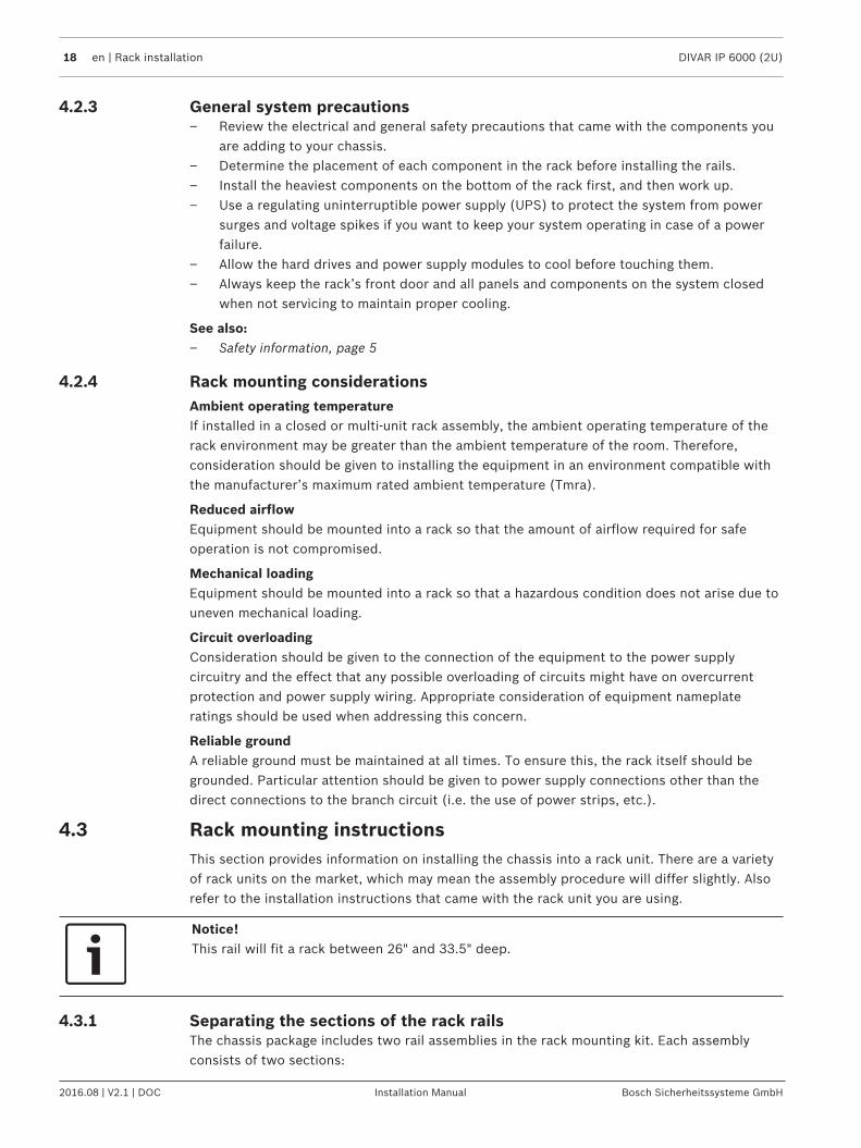
4.3.1 Separating the sections of the rack railsThe chassis package includes two rail assemblies in the rack mounting kit. Each assemblyconsists of two sections:
DIVAR IP 6000 (2U) Rack installation | en 19
Bosch Sicherheitssysteme GmbH Installation Manual 2016.08 | V2.1 | DOC
– an inner fixed chassis rail that secures directly to the chassis– an outer fixed rack rail that secures directly to the rack itself.
To separate the inner and outer rails:1. Locate the rail assembly in the chassis packaging.
2. Extend the rail assembly by pulling it outward.
3. Press the quick-release tab.
4. Separate the inner rail extension from the outer rail assembly.
4.3.2 Installing the inner rails on the chassisThe chassis includes a set of inner rails in two sections: inner rails and inner rail extensions.The inner rails are pre-attached to the chassis, and do not interfere with normal use of thechassis if you decide not to use a server rack. The inner rail extension is attached to the innerrail to mount the chassis in the rack.
!
Caution!Do not pick up the chassis with the front handles. They are designed to pull the system froma rack only.
20 en | Rack installation DIVAR IP 6000 (2U)
2016.08 | V2.1 | DOC Installation Manual Bosch Sicherheitssysteme GmbH
1
2
3
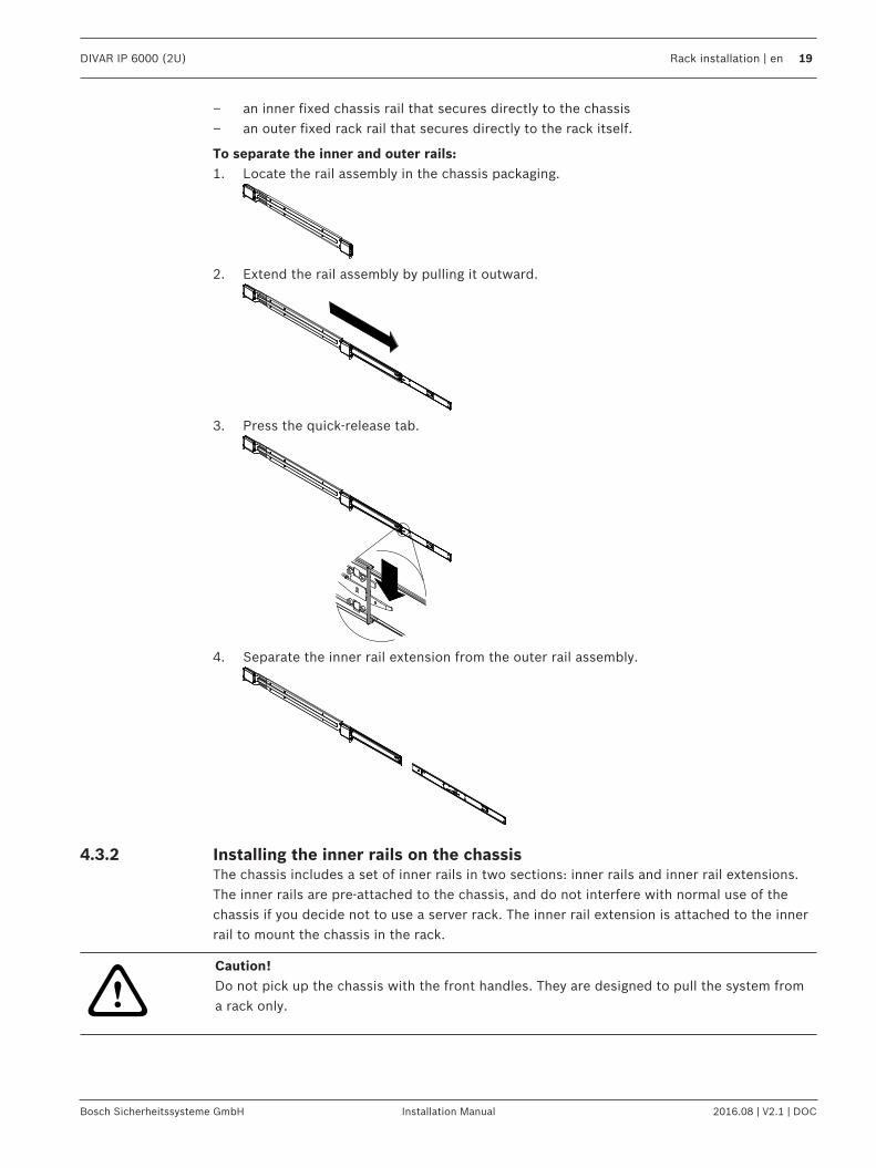
To install the inner rails:1. Place the inner rail extensions on the side of the chassis aligning the hooks of the chassis
with the rail extension holes. Make sure the extension faces "outward" just like the pre-attached inner rail.
2. Slide the extension toward the front of the chassis.3. Secure the chassis with 2 screws as illustrated.4. Repeat steps 1-3 for the other inner rail extension.
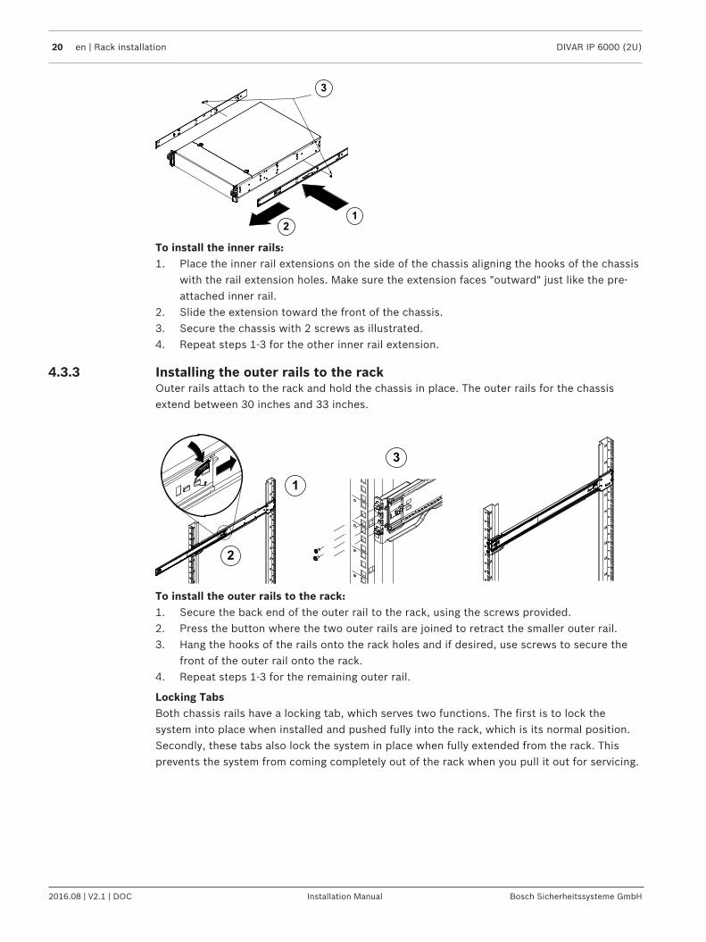
4.3.3 Installing the outer rails to the rackOuter rails attach to the rack and hold the chassis in place. The outer rails for the chassisextend between 30 inches and 33 inches.
1
2
3
To install the outer rails to the rack:1. Secure the back end of the outer rail to the rack, using the screws provided.2. Press the button where the two outer rails are joined to retract the smaller outer rail.3. Hang the hooks of the rails onto the rack holes and if desired, use screws to secure the
front of the outer rail onto the rack.4. Repeat steps 1-3 for the remaining outer rail.
Locking TabsBoth chassis rails have a locking tab, which serves two functions. The first is to lock thesystem into place when installed and pushed fully into the rack, which is its normal position.Secondly, these tabs also lock the system in place when fully extended from the rack. Thisprevents the system from coming completely out of the rack when you pull it out for servicing.
DIVAR IP 6000 (2U) Rack installation | en 21
Bosch Sicherheitssysteme GmbH Installation Manual 2016.08 | V2.1 | DOC
4.3.4 Installing the chassis in the rack
!
Warning!Stability hazardBefore sliding the unit out for servicing make sure that the rack stabilizing mechanism is inplace, or the rack is bolted to the floor. Failure to stabilize the rack can cause the rack to tipover.
!
Warning!Do not pick up the unit with the front handles. The handles are designed to pull the systemfrom a rack only.
Notice!Mounting the chassis into the rack requires at least two people to support the chassis duringinstallation. Please follow safety recommendations printed on the rails.
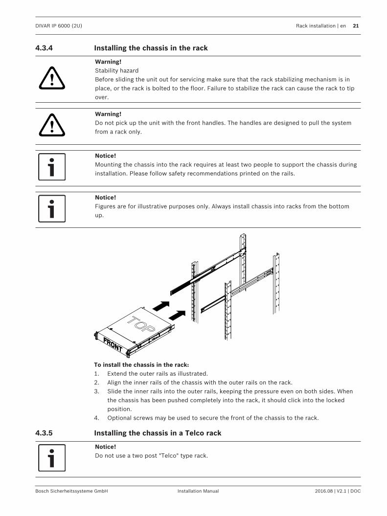
Notice!Figures are for illustrative purposes only. Always install chassis into racks from the bottomup.
To install the chassis in the rack:1. Extend the outer rails as illustrated.2. Align the inner rails of the chassis with the outer rails on the rack.3. Slide the inner rails into the outer rails, keeping the pressure even on both sides. When
the chassis has been pushed completely into the rack, it should click into the lockedposition.
4. Optional screws may be used to secure the front of the chassis to the rack.
4.3.5 Installing the chassis in a Telco rack
Notice!Do not use a two post "Telco" type rack.
22 en | Rack installation DIVAR IP 6000 (2U)
2016.08 | V2.1 | DOC Installation Manual Bosch Sicherheitssysteme GmbH
!
Warning!Stability hazardBefore sliding the unit out for servicing make sure that the rack stabilizing mechanism is inplace, or the rack is bolted to the floor. Failure to stabilize the rack can cause the rack to tipover.
!
Warning!Do not pick up the unit with the front handles. The handles are designed to pull the systemfrom a rack only.
Notice!Mounting the chassis into the rack requires at least two people to support the chassis duringinstallation. Please follow safety recommendations printed on the rails.
Notice!Figures are for illustrative purposes only. Always install chassis into racks from the bottomup.
To install the chassis into a Telco type rack, use two L-shaped brackets on either side of thechassis (four in total). First, determine how far the chassis will extend out the front of therack. Larger chassis should be positioned to balance the weight between front and back. If abezel is included on the chassis, remove it. Then attach the two front brackets to each side ofthe chassis, then the two rear brackets positioned with just enough space to accommodatethe width of the Telco rack. Finish by sliding the chassis into the rack and tightening thebrackets to the rack.
4.4 Turning on the systemTo turn on the system:1. Plug the power cord from the power supply unit into a high-quality power strip that offers
protection from electrical noise and power surges. We recommended using anuninterruptible power supply (UPS).
2. Press the power button on the control panel to turn on the system.
DIVAR IP 6000 (2U) System Setup – first Steps | en 23
Bosch Sicherheitssysteme GmbH Installation Manual 2016.08 | V2.1 | DOC
5 System Setup – first Steps5.1 Introduction
The DIVAR IP 6000 systems are based on Windows Storage Server 2012 R2 operating system.Windows Storage Server 2012 R2 systems provide a user interface for initial serverconfiguration, unified storage appliance management, simplified setup and storagemanagement, and support for Microsoft iSCSI Software Target.It is specially tuned to provide optimal performance for network-attached storage. WindowsStorage Server 2012 R2 operating system provides significant enhancements in storagemanagement scenarios, as well as integration of storage appliance management componentsand functionality.This chapter is valid for DIVAR IP 6000 2U models that come with pre-installed hard drives.The operating system of empty units loaded with third party hard drives will start normally,but the added hard drives must be configured with the RAID utility prior to initial softwaresetup.
See also– RAID setup, page 25
5.2 Setup instructionBy default the virtual network adapter (the two physical NIC ports are teamed by default) isconfigured to obtain a valid network address from a DHCP server in the local network. If thereis no DHCP server in the network, the system will use the following network settings:– IP address: 192.168.0.200– Subnet mask: 255.255.255.0– User: BVRAdmin– Password: WSS4Bosch
5.3 Setting the IP addressThe default IP address can be changed using:– Microsoft Utility Server Manager program
or– IP Helper tool
Notice!Changing the network settings using the IP Helper tool is only possible If the default systempassword is still unchanged.
Notice!We strongly recommend that you change the password of the administrative BVRAdmin useraccount after setting the IP address.
Microsoft Utility Server Manager programTo change the IP address using Microsoft Utility Server Manager program:4 Open the Microsoft Utility Server Manager and follow the instructions on the screen to
configure the network interface cards (NICs).
IP Helper toolThe IP Helper tool is available for download as follows:
24 en | System Setup – first Steps DIVAR IP 6000 (2U)
2016.08 | V2.1 | DOC Installation Manual Bosch Sicherheitssysteme GmbH
– in the online catalog on the DIVAR IP 6000 product page– under http://mydivar.com– under http://downloadstore.boschsecurity.com/To start the IP Helper tool:1. Double-click iphelper.exe.
2. A dialog box opens that displays all IP devices with their IP addresses located in thenetwork. Search for the devices whose network settings you want change.
3. Change the IP address.
5.4 Standard system configurationThe system is delivered with the fully configured iSCSI target and pre-configured LUNs.The default target name is TG0 and holds all of the iSCSI LUNs.The naming convention for the LUNs is VHDxx.vhdx where <xx> ranges from 01 up to <n>depending on the system used. The default setup allows every iSCSI Initiator (iSCSI host) toconnect to the system.The system comes with iSCSI Target Service enabled.
Notice!On empty systems you must set up the iSCSI target and the iSCSI LUNs of the drivesmanually after initial RAID configuration.
DIVAR IP 6000 (2U) RAID setup | en 25
Bosch Sicherheitssysteme GmbH Installation Manual 2016.08 | V2.1 | DOC
6 RAID setupIf you have added third party hard drives to empty units, you must configure the hard drivesusing the RAID setup utility. The RAID setup utility is pre-installed on the system.
Notice!The RAID setup process is not necessary for units with pre-installed hard drives. These unitsare delivered with a default configuration.
DIVAR IP systems are configured in RAID 5 mode by default. Alternatively, RAID 5+ or RAID 6can be used. In this case all settings remain unchanged except for the RAID level.
6.1 RAID setup using Remote Desktop ConnectionTo configure the hard drive using Remote Desktop Connection:1. Install all hard drives.2. Turn on the system.3. Open the Remote Desktop Connection and log on to DIVAR IP as follows.
– In the Computer box, enter the IP Address of the DIVAR IP system you want toconnect to.
– In the User name box, enter BVRAdmin.4. On the DIVAR IP desktop, double-click the MegaRAID Storage Manager icon.5. Enter user name and password, and then click Login.
– User name: BVRAdmin– Password: customer-dependent (default: WSS4Bosch)
6. Click Create Virtual Drive, then click Advanced mode.7. Select RAID 5 as RAID level (default configuration) and follow the steps in the Virtual
Drive wizard.8. Select and add all hard drives that are part of the RAID group (default: all).9. Click Create Drive Group.10. Change the following settings:
– Initialization state: Fast Initialization– Strip size: 64 KB– Write policy: Always Write Back
Note: All other settings remain unchanged.11. Click Create Virtual Drive.12. Finish the wizard and exit the MegaRAID Storage Manager program.
13. On the DIVAR IP desktop, double-click the Server Manager icon.14. Click File and Storage Services > Disks.15. Right-click the disk named LSI…, then click New Volume.16. Run through the wizard without changing the default settings.17. Change the Volume label to Data.18. Finish the wizard and exit the Server Manager program.
Notice!Before you can store video recordings on the drive, you must perform a basic setup using thevideo software configuration tool, for example, Configuration Manager or Bosch VMSConfiguration Client.
26 en | RAID setup DIVAR IP 6000 (2U)
2016.08 | V2.1 | DOC Installation Manual Bosch Sicherheitssysteme GmbH
See also– Setting the IP address, page 23
6.2 RAID setup using RAID BIOSTo configure the hard drive using RAID BIOS:1. Install all hard drives.2. Turn on the system and press Ctrl+R when MegaRAID Configuration Utility is displayed
on the screen. The display appears before Windows starts.3. In the MegaRAID Configuration Utility program, select Create Virtual Drive.4. Apply the following settings:
– RAID Level: RAID-5– Under Advanced settings:
Strip Size: 64KBWrite Policy: Write BackNote: All other settings remain unchanged.
5. Select all hard drives that are part of the RAID group.6. Start the virtual drive initialization.7. Exit the MegaRAID Configuration Utility program.8. Perform a complete system recovery (Initial Factory Setup).
See also– Recovering the unit, page 27
DIVAR IP 6000 (2U) Recovering the unit | en 27
Bosch Sicherheitssysteme GmbH Installation Manual 2016.08 | V2.1 | DOC
7 Recovering the unitFollowing procedure describes how to restore the factory default image.
To restore the unit to factory default image1. Turn on the unit and insert the system recovery DVD.
Notice!Make sure that a VGA monitor, a keyboard and a mouse are connected to the unit.
2. Press any key when prompted to start the recovery environment from DVD.Note: Press any key only to start the recovery environment. Do not press any key duringthe setup process.
3. Select one of the following:– Initial Factory Setup (all data on the system will be lost)
(restores to factory default image and deletes all data on the hard drives)or
– System Recovery (back to Factory Defaults)(restores to factory default image; data on the hard drives will not be deleted)
Note:Windows performs the setup. The screen displays the percentage of the process.
Notice!Do not turn off the unit during the process. This will damage the Recovery media.
4. The unit starts from the Recovery media. If the setup is successful, press Yes to restartthe system.
5. Windows performs the initial setup of the operating system. The unit restarts afterWindows has completed the setup.
6. After the restart of the unit, the factory default settings are installed and the Windowslogon screen is displayed.The factory default settings are:– IP address: DHCP (Fallback: 192.168.0.200)– Subnet mask: 255.255.255.0– User: BVRAdmin– Password: WSS4Bosch
28 en | Additional software and documentation DIVAR IP 6000 (2U)
2016.08 | V2.1 | DOC Installation Manual Bosch Sicherheitssysteme GmbH
8 Additional software and documentationSoftware for configuration of hardware and software is available on the online productcatalogue.
Documentation and software for Bosch Security Systems products can be found in theonline product catalogue as follows:4 Open any browser > enter www.boschsecurity.com > select your region and your country
> start a search for your product > select the product in the search results to show theexisting files.
DIVAR IP 6000 (2U) OSS licenses | en 29
Bosch Sicherheitssysteme GmbH Installation Manual 2016.08 | V2.1 | DOC
9 OSS licensesThis chapter provides an overview on used Open Source Licenses in DIVAR IP 6000. Thelicense packages are either used completely or only some parts within a package are used.
9.1 MIT - iniparser
30 en | OSS licenses DIVAR IP 6000 (2U)
2016.08 | V2.1 | DOC Installation Manual Bosch Sicherheitssysteme GmbH
9.2 MS-PL - MSDN Library
DIVAR IP 6000 (2U) OSS licenses | en 31
Bosch Sicherheitssysteme GmbH Installation Manual 2016.08 | V2.1 | DOC
9.3 NTP License - NTP Project
32 en | Maintenance DIVAR IP 6000 (2U)
2016.08 | V2.1 | DOC Installation Manual Bosch Sicherheitssysteme GmbH
10 MaintenanceThis chapter covers the steps required to install components and perform maintenance on thechassis.
Notice!Installation should only be carried out by qualified customer service personnel in accordancewith the applicable electrical regulations.
!
Caution!Review the warnings and precautions listed in the manual before setting up or servicing thischassis.
10.1 Replacement componentsAlthough not frequently, you may need replacement parts for your system. To ensure thehighest level of professional service and technical support, you must register the systemsaccording to the instructions available as part of the shipment as well as online from theBosch product catalog.
10.2 Removing power from the systemBefore performing some setup or maintenance tasks, use the following procedure to ensurethat power has been removed from the system.To remove the power:1. Shut down the system.2. Remove the power cords from the power supplies.3. Disconnect the cord from the power strip or wall outlet.
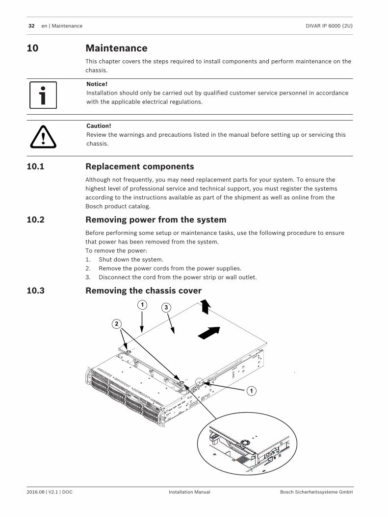
10.3 Removing the chassis cover1
1
2
3
DIVAR IP 6000 (2U) Maintenance | en 33
Bosch Sicherheitssysteme GmbH Installation Manual 2016.08 | V2.1 | DOC
1 Fixing screws 2 Release tabs
3 Chassis cover
To remove the chassis cover:1. Disconnect the power supply, lay the chassis on a flat surface.2. Remove the two screws on each side of the cover, which secure the cover to the chassis.3. Press the release tabs to remove the cover from the locked position. Press both tabs at
the same time.4. Once the top cover is released from the locked position, slide the cover toward the rear
of the chassis and lift the cover off the chassis.
Notice!Except for short periods of time, do NOT operate the server without the cover in place. Thechassis cover must be in place to allow proper airflow and prevent overheating.
10.4 Installing a SATA hard driveThis chapter describes the removing and installing of SATA hard drives.
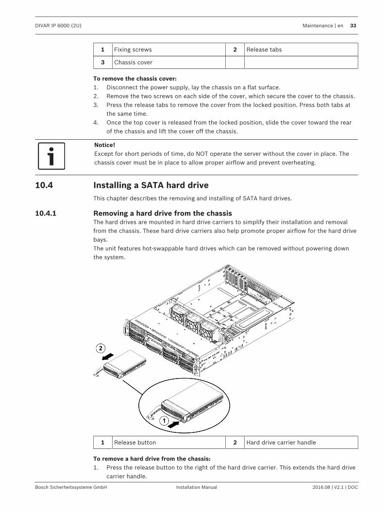
10.4.1 Removing a hard drive from the chassisThe hard drives are mounted in hard drive carriers to simplify their installation and removalfrom the chassis. These hard drive carriers also help promote proper airflow for the hard drivebays.The unit features hot-swappable hard drives which can be removed without powering downthe system.
1 Release button 2 Hard drive carrier handle
To remove a hard drive from the chassis:1. Press the release button to the right of the hard drive carrier. This extends the hard drive
carrier handle.
34 en | Maintenance DIVAR IP 6000 (2U)
2016.08 | V2.1 | DOC Installation Manual Bosch Sicherheitssysteme GmbH
2. Use the handle to pull the drive out of the chassis.
Notice!Except for short periods of time (swapping hard drives), do not operate the unit with thehard drives removed from the bays.
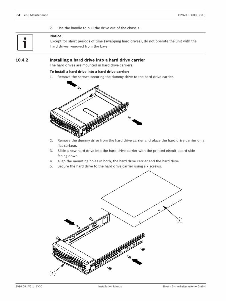
10.4.2 Installing a hard drive into a hard drive carrierThe hard drives are mounted in hard drive carriers.
To install a hard drive into a hard drive carrier:1. Remove the screws securing the dummy drive to the hard drive carrier.
2. Remove the dummy drive from the hard drive carrier and place the hard drive carrier on aflat surface.
3. Slide a new hard drive into the hard drive carrier with the printed circuit board sidefacing down.
4. Align the mounting holes in both, the hard drive carrier and the hard drive.5. Secure the hard drive to the hard drive carrier using six screws.
DIVAR IP 6000 (2U) Maintenance | en 35
Bosch Sicherheitssysteme GmbH Installation Manual 2016.08 | V2.1 | DOC
1 Hard drive carrier 2 SATA hard drive
6. Replace the hard drive carrier into the chassis bay. Make sure that the hard drive carrierhandle is completely closed.
Notice!We recommend using the respective Bosch hard disk drives. The hard disk drives as one ofthe critical component are carefully selected by Bosch based on available failure rates. HDD –not delivered from Bosch – are not supported. Information on supported HDDs can be foundin the datasheet in the Bosch Online Product Catalog.
See also– Installing a hard drive into a front drive bay, page 35
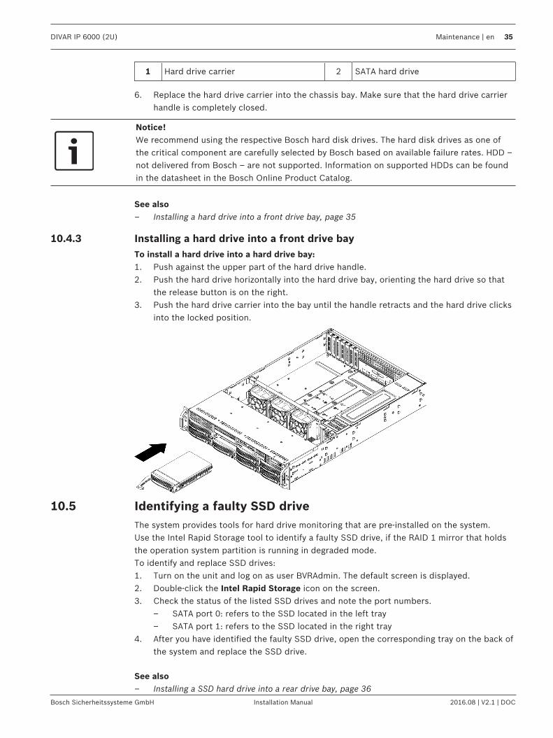
10.4.3 Installing a hard drive into a front drive bayTo install a hard drive into a hard drive bay:1. Push against the upper part of the hard drive handle.2. Push the hard drive horizontally into the hard drive bay, orienting the hard drive so that
the release button is on the right.3. Push the hard drive carrier into the bay until the handle retracts and the hard drive clicks
into the locked position.
10.5 Identifying a faulty SSD driveThe system provides tools for hard drive monitoring that are pre-installed on the system.Use the Intel Rapid Storage tool to identify a faulty SSD drive, if the RAID 1 mirror that holdsthe operation system partition is running in degraded mode.To identify and replace SSD drives:1. Turn on the unit and log on as user BVRAdmin. The default screen is displayed.2. Double-click the Intel Rapid Storage icon on the screen.3. Check the status of the listed SSD drives and note the port numbers.
– SATA port 0: refers to the SSD located in the left tray– SATA port 1: refers to the SSD located in the right tray
4. After you have identified the faulty SSD drive, open the corresponding tray on the back ofthe system and replace the SSD drive.
See also– Installing a SSD hard drive into a rear drive bay, page 36

36 en | Maintenance DIVAR IP 6000 (2U)
2016.08 | V2.1 | DOC Installation Manual Bosch Sicherheitssysteme GmbH
10.6 Installing a SSD hard drive into a rear drive bayThis chapter describes the removing and installing of SSD hard drives on the rear side of thechassis.
10.6.1 Removing a hard drive from the rear drive bayThe unit features two hot-swappable hard drives on the rear side which can be removedwithout powering down the system.The hard drives are mounted in hard drive carriers to simplify their installation and removalfrom the chassis. These hard drive carriers also help promote proper airflow for the hard drivebays.
To remove a hard drive from the chassis:1. Press the release button to the right of the hard drive carrier. This extends the hard drive
carrier handle.2. Use the handle to pull the drive out of the chassis.
Notice!Except for short periods of time (swapping hard drives), do not operate the unit with thehard drives removed from the bays.
10.6.2 Installing a hard drive into a rear hard drive carrierThe hard drives are mounted in hard drive carriers.
To install a hard drive into the rear hard drive carrier:1. Remove the screws securing the dummy drive to the hard drive carrier.2. Remove the dummy drive from the hard drive carrier.3. Insert a hard drive into the hard drive carrier with the printed circuit board side facing
down and the connector end toward the rear of the carrier.4. Align the mounting holes in both, the hard drive carrier and the hard drive.
Note: There are mounting holes in the hard drive carrier marked "SAS" or “SATA” to aid incorrect installation.
DIVAR IP 6000 (2U) Maintenance | en 37
Bosch Sicherheitssysteme GmbH Installation Manual 2016.08 | V2.1 | DOC
5. Secure the hard drive to the hard drive carrier with four screws. Use the four M3 flat-headscrews included in the hard disk bag of your accessory box.Note: To secure the hard drive, you cannot reuse the screws that are used to secure thedummy drive to the tray.
Notice!We recommend using the respective Bosch hard disk drives. The hard disk drives as one ofthe critical component are carefully selected by Bosch based on available failure rates. HDD –not delivered from Bosch – are not supported. Information on supported HDDs can be foundin the datasheet in the Bosch Online Product Catalog.
10.6.3 Installing a hard drive into a rear drive bayTo install a hard drive into a hard drive bay:1. Push against the upper part of the hard drive handle.2. Push the hard drive vertically into the hard drive bay.3. Push the hard drive carrier into the bay until the handle retracts and the hard drive clicks
into the locked position.
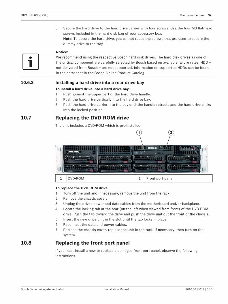
10.7 Replacing the DVD ROM driveThe unit includes a DVD-ROM which is pre-installed.
1 2
1 DVD-ROM 2 Front port panel
To replace the DVD-ROM drive:1. Turn off the unit and if necessary, remove the unit from the rack.2. Remove the chassis cover.3. Unplug the drives power and data cables from the motherboard and/or backplane.4. Locate the locking tab at the rear (on the left when viewed from front) of the DVD-ROM
drive. Push the tab toward the drive and push the drive unit out the front of the chassis.5. Insert the new drive unit in the slot until the tab locks in place.6. Reconnect the data and power cables.7. Replace the chassis cover. replace the unit in the rack, if necessary, then turn on the
system.
10.8 Replacing the front port panelIf you must install a new or replace a damaged front port panel, observe the followinginstructions.
38 en | Maintenance DIVAR IP 6000 (2U)
2016.08 | V2.1 | DOC Installation Manual Bosch Sicherheitssysteme GmbH
1 2
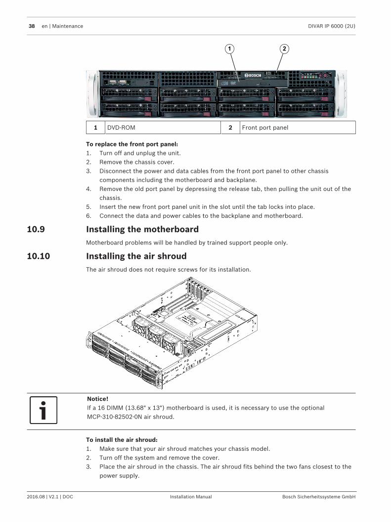
1 DVD-ROM 2 Front port panel
To replace the front port panel:1. Turn off and unplug the unit.2. Remove the chassis cover.3. Disconnect the power and data cables from the front port panel to other chassis
components including the motherboard and backplane.4. Remove the old port panel by depressing the release tab, then pulling the unit out of the
chassis.5. Insert the new front port panel unit in the slot until the tab locks into place.6. Connect the data and power cables to the backplane and motherboard.
10.9 Installing the motherboardMotherboard problems will be handled by trained support people only.
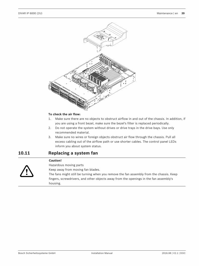
10.10 Installing the air shroudThe air shroud does not require screws for its installation.
Notice!If a 16 DIMM (13.68" x 13") motherboard is used, it is necessary to use the optionalMCP-310-82502-0N air shroud.
To install the air shroud:1. Make sure that your air shroud matches your chassis model.2. Turn off the system and remove the cover.3. Place the air shroud in the chassis. The air shroud fits behind the two fans closest to the
power supply.
DIVAR IP 6000 (2U) Maintenance | en 39
Bosch Sicherheitssysteme GmbH Installation Manual 2016.08 | V2.1 | DOC
To check the air flow:1. Make sure there are no objects to obstruct airflow in and out of the chassis. In addition, if
you are using a front bezel, make sure the bezel's filter is replaced periodically.2. Do not operate the system without drives or drive trays in the drive bays. Use only
recommended material.3. Make sure no wires or foreign objects obstruct air flow through the chassis. Pull all
excess cabling out of the airflow path or use shorter cables. The control panel LEDsinform you about system status.
10.11 Replacing a system fan
!
Caution!Hazardous moving partsKeep away from moving fan blades. The fans might still be turning when you remove the fan assembly from the chassis. Keepfingers, screwdrivers, and other objects away from the openings in the fan assembly'shousing.
40 en | Maintenance DIVAR IP 6000 (2U)
2016.08 | V2.1 | DOC Installation Manual Bosch Sicherheitssysteme GmbH
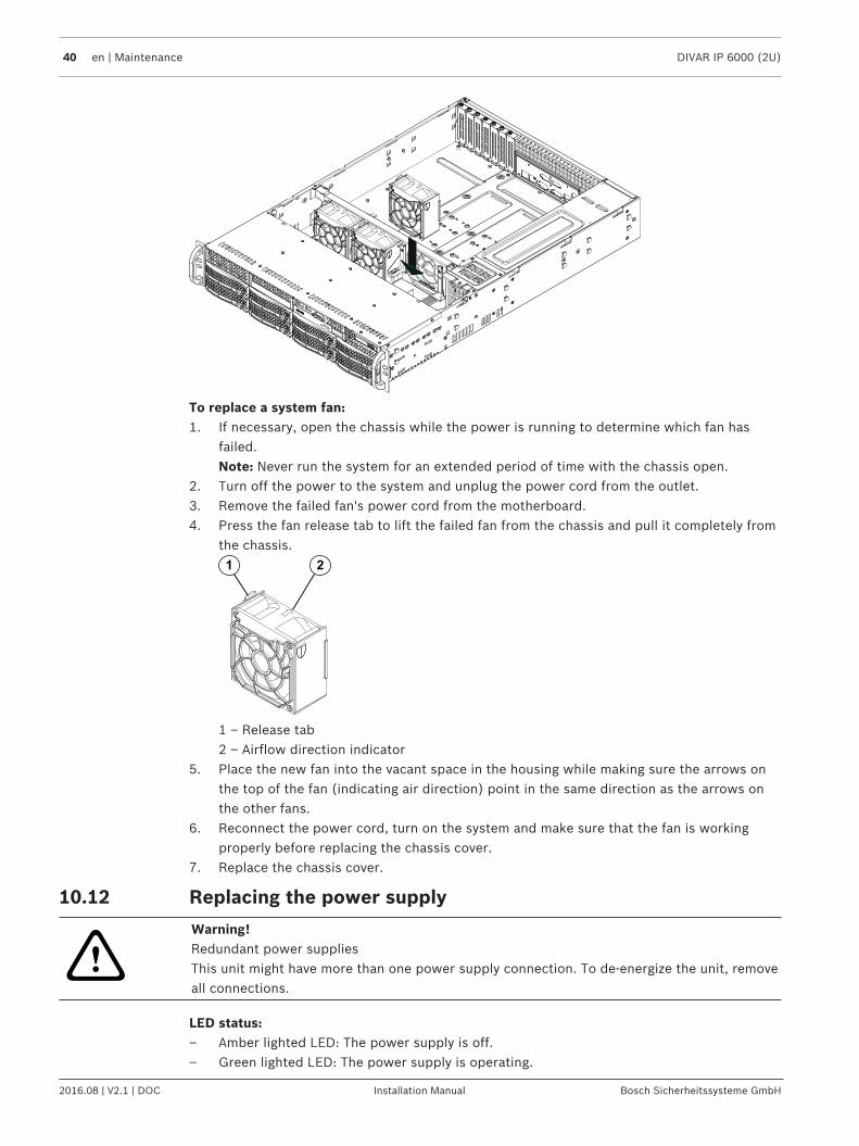
To replace a system fan:1. If necessary, open the chassis while the power is running to determine which fan has
failed.Note: Never run the system for an extended period of time with the chassis open.
2. Turn off the power to the system and unplug the power cord from the outlet.3. Remove the failed fan's power cord from the motherboard.4. Press the fan release tab to lift the failed fan from the chassis and pull it completely from
the chassis.1 2
1 – Release tab2 – Airflow direction indicator
5. Place the new fan into the vacant space in the housing while making sure the arrows onthe top of the fan (indicating air direction) point in the same direction as the arrows onthe other fans.
6. Reconnect the power cord, turn on the system and make sure that the fan is workingproperly before replacing the chassis cover.
7. Replace the chassis cover.
10.12 Replacing the power supply
!
Warning!Redundant power suppliesThis unit might have more than one power supply connection. To de-energize the unit, removeall connections.
LED status:– Amber lighted LED: The power supply is off.– Green lighted LED: The power supply is operating.
DIVAR IP 6000 (2U) Maintenance | en 41
Bosch Sicherheitssysteme GmbH Installation Manual 2016.08 | V2.1 | DOC
See also– Power supply, page 13
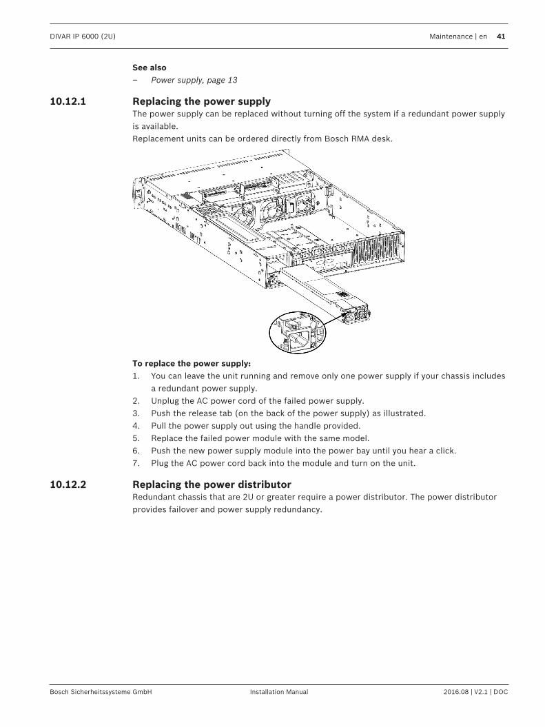
10.12.1 Replacing the power supplyThe power supply can be replaced without turning off the system if a redundant power supplyis available.Replacement units can be ordered directly from Bosch RMA desk.
To replace the power supply:1. You can leave the unit running and remove only one power supply if your chassis includes
a redundant power supply.2. Unplug the AC power cord of the failed power supply.3. Push the release tab (on the back of the power supply) as illustrated.4. Pull the power supply out using the handle provided.5. Replace the failed power module with the same model.6. Push the new power supply module into the power bay until you hear a click.7. Plug the AC power cord back into the module and turn on the unit.
10.12.2 Replacing the power distributorRedundant chassis that are 2U or greater require a power distributor. The power distributorprovides failover and power supply redundancy.
42 en | Maintenance DIVAR IP 6000 (2U)
2016.08 | V2.1 | DOC Installation Manual Bosch Sicherheitssysteme GmbH
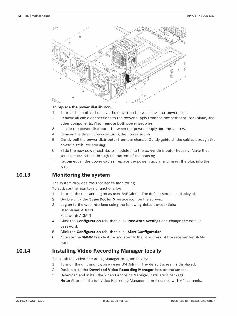
To replace the power distributor:1. Turn off the unit and remove the plug from the wall socket or power strip.2. Remove all cable connections to the power supply from the motherboard, backplane, and
other components. Also, remove both power supplies.3. Locate the power distributor between the power supply and the fan row.4. Remove the three screws securing the power supply.5. Gently pull the power distributor from the chassis. Gently guide all the cables through the
power distributor housing.6. Slide the new power distributor module into the power distributor housing. Make that
you slide the cables through the bottom of the housing.7. Reconnect all the power cables, replace the power supply, and insert the plug into the
wall.
10.13 Monitoring the systemThe system provides tools for health monitoring.To activate the monitoring functionality:1. Turn on the unit and log on as user BVRAdmin. The default screen is displayed.2. Double-click the SuperDoctor 5 service icon on the screen.3. Log on to the web interface using the following default credentials:
User Name: ADMINPassword: ADMIN
4. Click the Configuration tab, then click Password Settings and change the defaultpassword.
5. Click the Configuration tab, then click Alert Configuration.6. Activate the SNMP Trap feature and specify the IP address of the receiver for SNMP
traps.
10.14 Installing Video Recording Manager locallyTo install the Video Recording Manager program locally:1. Turn on the unit and log on as user BVRAdmin. The default screen is displayed.2. Double-click the Download Video Recording Manager icon on the screen.3. Download and install the Video Recording Manager installation package.
Note: After installation Video Recording Manager is pre-licensed with 64 channels.
DIVAR IP 6000 (2U) Maintenance | en 43
Bosch Sicherheitssysteme GmbH Installation Manual 2016.08 | V2.1 | DOC
Notice!For detailed information using the program, refer to the Video Recording Managerdocumentation.
10.15 Service and repairThe storage system is backed by a 3-year warranty. Issues will be handled according to BoschService and Support guidelines.The storage equipment is shipped with an original manufacturer Service and Supportagreement.Bosch RMA Desk is the Single Point of Contact in case of failure but the Service and Supportobligations are fulfilled by the manufacturer or a partner.In order to enable the manufacturer's Service and Support organization to fulfill the definedService Levels, the system must be re-registered. Otherwise, the defined service level cannotbe provided but only best effort.A description what information is required and where to send is included in each shipment aspaper work. The description is also electronically available in the Bosch online productcatalogue.
Request for RMAPlease request an RMA for failed parts from one of the following Bosch RMA contacts.– RMA Contact AMEC
Bosch ST, RMA Swapstock, 8601 East Cornhusker Hwy, Lincoln, NE 68507 -USAPhone: +1(402)467-6610Fax: n.a.E-mail: [email protected] Hours: Monday to Friday, 06:00 – 16:30
– RMA Desk APRRobert Bosch (SEA) Pte Ltd, 11 Bishan Street 21, (level 5, from service lift), Singapore573943Phone: +65 6571 2872Fax: n.a.Email: [email protected] Hours: Monday to Friday, 08:30 – 17:45
– RMA contact ChinaBosch (Zhuhai) Security Systems Co. Ltd. Ji Chang Bei Road 20#, Qingwan IndustrialEstate; Sanzao Town, Jinwan District, Zhuhai; P.R. China; Postal Code: 519040Phone: +86 756 7633117 / 121Fax: n.a.Email: [email protected] Hours: Monday to Friday, 08:30 – 17:30
– RMA Contact EMEABosch Security Systems, C/o EVI Audio GmbH, Ernst-Heinkel Str. 4, 94315 Straubing,GERMANYContact person: RA Desk SupervisorPhone: +49(9421)706-366Fax: n.a.E-mail: [email protected] Hours: Monday to Friday, 07:00 – 18:00


Bosch Sicherheitssysteme GmbHRobert-Bosch-Ring 585630 GrasbrunnGermanywww.boschsecurity.com© Bosch Sicherheitssysteme GmbH, 2016