Embed Size (px)
Citation preview
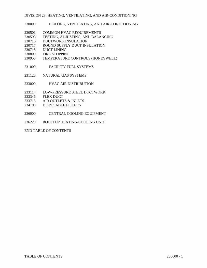
TABLE OF CONTENTS 230000 - 1
DIVISION 23: HEATING, VENTILATING, AND AIR-CONDITIONING
230000 HEATING, VENTILATING, AND AIR-CONDITIONING
230501 COMMON HVAC REQUIREMENTS
230593 TESTING, ADJUSTING, AND BALANCING
230716 DUCTWORK INSULATION
230717 ROUND SUPPLY DUCT INSULATION
230718 DUCT LINING
230800 FIRE STOPPING
230953 TEMPERATURE CONTROLS (HONEYWELL)
231000 FACILITY FUEL SYSTEMS
231123 NATURAL GAS SYSTEMS
233000 HVAC AIR DISTRIBUTION
233114 LOW-PRESSURE STEEL DUCTWORK
233346 FLEX DUCT
233713 AIR OUTLETS & INLETS
234100 DISPOSABLE FILTERS
236000 CENTRAL COOLING EQUIPMENT
236220 ROOFTOP HEATING-COOLING UNIT
END TABLE OF CONTENTS
COMMON HVAC REQUIREMENTS 230501 - 1
SECTION 230501 – COMMON HVAC REQUIREMENTS
PART 1 - GENERAL
1.1 RELATED DOCUMENTS
A. Drawings and General Provisions of Contract, including General and Supplementary Conditions
and other Division 1 Specification Sections, apply to this Section.
1.2 SUMMARY
A. Furnish labor, materials, and equipment necessary for completion of work as described in
Contract Documents.
B. It is the intent of these specifications that the systems specified herein are to be complete and
operational before being turned over to the owner. During the bidding process, the contractor is
to ask questions or call to the engineer’s attention any items that are not shown or may be
required to make the system complete and operational. Once the project is bid and the
contractor has accepted the contract, it is his responsibility to furnish and install all equipment
and parts necessary to provide a complete and operational system without additional cost to the
owner.
C. Furnish and install fire stopping materials to seal penetrations through fire rated structures and
draft stops.
D. Includes But Not Limited To:
1. General procedures and requirements for HVAC.
E. Related Sections:
1. Section 23 0593: Testing, Adjusting, and Balancing for HVAC.
1.3 SUBMITTALS
A. Substitutions: By specific designation and description, standards are established for specialties
and equipment. Other makes of specialties and equipment of equal quality will be considered
provided such proposed substitutions are submitted to the Architect for his approval, complete
with specification data showing how it meets the specifications, at least 5 working days prior to
bid opening. A list of approved substitutions will be published as an addendum.
1. Submit a single copy of Manufacturer's catalog data including Manufacturer's complete
specification for each proposed substitution.
2. The Architect or Engineer is to be the sole judge as to the quality of any material offered
as an equal.
B. Product Data, Shop Drawings: Within 30 days after award of contract, submit 10 sets of
Manufacturer's catalog data for each manufactured item.
1. Literature shall include enough information to show complete compliance with Contract
Document requirements.
2. Mark literature to indicate specific item with applicable data underlined.
3. Information shall include but not be limited to capacities, ratings, type of material used,
guarantee, and such dimensions as are necessary to check space requirements.
4. When accepted, submittal shall be an addition to Contract Documents and shall be in
equal force. No variation shall be permitted.
COMMON HVAC REQUIREMENTS 230501 - 2
5. Even though the submittals have been accepted by the Engineer, it does not relieve the
contractor from meeting all of the requirements of the plans and specifications and
providing a complete and operational system.
C. Drawings of Record: One complete sets of blue line mechanical drawings shall be provided for
the purpose of showing a complete picture of the work as actually installed.
1. These drawings shall serve as work progress report sheets. Contractor shall make
notations neat and legible therein daily as the work proceeds.
2. The drawings shall be kept at the job at a location designated by the Mechanical
Engineer.
3. At completion of the project these "as-built" drawings shall be signed by the Contractor,
dated, and returned to the Architect.
D. Operating Instructions and Service Manual: The Mechanical Contractor shall prepare 2 copies
of an Operation and Maintenance Manual for all mechanical systems and equipment used in this
project. Manuals shall be bound in hard-backed binders and the front cover and spine of each
binder shall indicate the name and location of the project. Use plastic tab indexes for all
sections. Provide a section for each different type of equipment item. The following items
shall be included in the manual, together with any other pertinent data. This list is not complete
and is to be used as a guide.
1. Provide a master index at the beginning of the manual showing all items included.
2. The first section of the manual shall contain:
a. Names, addresses, and telephone numbers of Architect, Mechanical Engineer,
Electrical Engineer, General Contractor, Plumbing Contractor, Sheet Metal
Contractor, and Temperature Control Contractor.
b. List of Suppliers which shall include a complete list of each piece of equipment used
with the name, address, and telephone number of vendor.
c. General Description of Systems including –
1) Location of all major equipment
2) Description of the various mechanical systems
3) Description of operation and control of the mechanical systems
4) Suggested maintenance schedule
d. Copy of contractor's written warranty
3. Provide a copy of approved submittal literature for each piece of equipment.
4. Provide maintenance and operation literature published by the manufacturer for each
piece of equipment which includes: oiling, lubrication and greasing data; belt sizes, types
and lengths; wiring diagrams; step-by-step procedure to follow in putting each piece of
mechanical equipment in operation.
5. Include parts numbers of all replaceable items.
6. Provide control diagram and operation sequence, along with labeling of control piping
and instruments to match diagram.
7. Include a valve chart indicating valve locations.
E. Include air balance and/or water balance reports.
1.4 SUBMITTALS FOR COMMON HVAC REQUIREMENTS
A. Samples: Sealer and gauze proposed for sealing ductwork.
B. Quality Assurance / Control:
1. Manufacturer’s installation manuals providing detailed instructions on assembly, joint
sealing, and system pressure testing for leaks.
2. Specification data on sealer and gauze proposed for sealing ductwork.
COMMON HVAC REQUIREMENTS 230501 - 3
C. Quality Assurance
1. Requirements: Construction details not specifically called out in Contract Documents
shall conform to applicable requirements of SMACNA HVAC Duct Construction
Standards.
2. Pre-Installation Conference: Schedule conference immediately before installation of
ductwork.
1.5 QUALITY ASSURANCE
A. Requirements of Regulatory Agencies:
1. Perform work in accordance with applicable provisions of local and state Plumbing Code,
Gas Ordinances, and adoptions thereof. Provide materials and labor necessary to comply
with rules, regulations, and ordinances.
2. In case of differences between building codes, state laws, local ordinances, utility
company regulations, and Contract Documents, the most stringent shall govern.
Promptly notify Architect in writing of such differences.
B. Applicable Specifications: Referenced specifications, standards, and publications shall be of
the issues in effect on date of Advertisement for Bid.
1. "Heating, Ventilating and Air Conditioning Guide" published by the American Society of
Heating and Air Conditioning Engineers.
2. "Engineering Standards" published by the Heating, Piping, and Air Conditioning
Contractors National Association.
3. "2015 International Building Code", "2015 International Mechanical Code", “2015
International Plumbing Code” and "2015 International Fire Code" as published by the
International Conference of Building Officials.
4. "National Electrical Code" as published by the National Fire Protection Association.
5. "2015 International Energy Conservation Code ".
C. Identification: Motor and equipment name plates as well as applicable UL and AGA labels
shall be in place when Project is turned over to Owner.
1.6 INSPECTIONS AND PERMITS
A. Pay for permits, fees, or charges for inspection or other services. Local and state codes and
ordinances must be properly executed without expense to Owner and are considered as
minimum requirements. Local and state codes and ordinances do not relieve the Contractor
from work shown that exceeds minimum requirements.
1.7 ADDITIONAL WORK:
A. Design is based on equipment as described in the drawing equipment schedule. Any change in
foundation bases, electrical wiring, conduit connections, piping, controls and openings required
by alternate equipment submitted and approved shall be paid for by this division. All work
shall be in accordance with the requirements of the applicable sections.
PART 2 - PRODUCTS FOR COMMON HVAC REQUIREMENTS
A. Finishes, Where Applicable: Colors as selected by Architect.
B. Duct Hangers:
1. One inch 25 mm by 18 ga 1.27 mm galvanized steel straps or steel rods as shown on
Drawings, and spaced not more than 96 inches 2 400 mm apart. Do not use wire hangers.
COMMON HVAC REQUIREMENTS 230501 - 4
2. Attaching screws at trusses shall be 2 inch 50 mm No. 10 round head wood screws. Nails
not allowed.
PART 3 - EXECUTION
3.1 EXAMINATION
A. Site Inspection:
1. Examine premises and understand the conditions which may affect performance of work
of this Division before submitting proposals for this work.
2. No subsequent allowance for time or money will be considered for any consequence
related to failure to examine site conditions.
B. Drawings:
1. Mechanical drawings show general arrangement of piping, ductwork, equipment, etc, and
do not attempt to show complete details of building construction which affect installation.
This Contractor shall refer to architectural, structural, and electrical drawings for
additional building detail which affect installation of his work.
a. Follow mechanical drawings as closely as actual building construction and work of
other trades will permit.
b. No extra payments will be allowed where piping and/or ductwork must be offset to
avoid other work or where minor changes are necessary to facilitate installation.
c. Everything shown on the mechanical drawings shall be the responsibility of
Mechanical Contractor unless specifically noted otherwise.
2. Consider architectural and structural drawings part of this work insofar as these drawings
furnish information relating to design and construction of building. These drawings take
precedence over mechanical drawings.
3. Because of small scale of mechanical drawings, it is not possible to indicate all offsets,
fittings, and accessories which may be required. Investigate structural and finish
conditions affecting this work and arrange work accordingly, providing such fittings,
valves, and accessories required to meet conditions. Do not scale drawings for locations
of equipment or piping. Refer to large scale dimensioned drawings for exact locations.
C. Insure that items to be furnished fit space available. Make necessary field measurements to
ascertain space requirements including those for connections and furnish and install equipment
of size and shape so final installation shall suit true intent and meaning of Contract Documents.
1. If approval is received to use other than specified items, responsibility for specified
capacities and insuring that items to be furnished will fit space available lies with this
Division.
2. If non-specified equipment is used and it will not fit job site conditions, this Contractor
assumes responsibility for replacement with items named in Contract Documents.
3.2 PREPARATION
A. Cut carefully to minimize necessity for repairs to existing work. Do not cut beams, columns, or
trusses.
1. Patch and repair walls, floors, ceilings, and roofs with materials of same quality and
appearance as adjacent surfaces unless otherwise shown. Surface finishes shall exactly
match existing finishes of same materials.
2. Each Section of this Division shall bear expense of cutting, patching, repairing, and
replacing of work of other Sections required because of its fault, error, tardiness, or
because of damage done by it.
3. Cutting, patching, repairing, and replacing pavements, sidewalks, roads, and curbs to
permit installation of work of this Division is responsibility of Section installing work.
COMMON HVAC REQUIREMENTS 230501 - 5
3.3 INSTALLATION
A. Arrange pipes, ducts, and equipment to permit ready access to valves, unions, traps, starters,
motors, control components, and to clear openings of doors and access panels.
3.4 STORAGE AND PROTECTION OF MATERIALS:
A. Provide storage space for storage of materials and assume complete responsibility for losses due
to any cause whatsoever. Storage shall not interfere with traffic conditions in any public
thoroughfare.
B. Protect completed work, work underway, and materials against loss or damage.
C. Close pipe openings with caps or plugs during installation. Cover fixtures and equipment and
protect against dirt, or injury caused by water, chemical, or mechanical accident.
3.5 EXCAVATION AND BACKFILL
A. Perform necessary excavation of whatever substance encountered for proper laying of all pipes
and underground ducts.
1. Excavated materials not required for fill shall be removed from site as directed by
Engineer.
2. Excavation shall be carried low enough to allow a minimum coverage over underground
piping of 5'-0" or to be below local frost level.
3. Excess excavation below required level shall be backfilled at Contractor's expense with
earth, sand, or gravel as directed by Engineer. Tamp ground thoroughly.
4. Ground adjacent to all excavations shall be graded to prevent water running into
excavated areas.
B. Backfill pipe trenches and allow for settlement.
1. Backfill shall be mechanically compacted to same density as surrounding undisturbed
earth.
2. Cinders shall not be used in backfilling where steel or iron pipe is used.
3. No backfilling shall be done until installation has been approved by the Engineer.
3.6 COOPERATION
A. Cooperate with other crafts in coordination of work. Promptly respond when notified that
construction is ready for installation of work under Division 23000. Contractor will be held
responsible for any delays which might be caused by his negligence or failure to cooperate with
the other Contractors or crafts.
3.7 SUPERVISION
A. Provide a competent superintendent in charge of the work at all times. Anyone found
incompetent shall be removed at once and replaced by someone satisfactory, when requested by
the Architect.
3.8 INSTALLATION CHECK:
A. An experienced, competent, and authorized representative of the manufacturer or supplier of
each item of equipment indicated in the equipment schedule shall visit the project to inspect,
check, adjust if necessary, and approve the equipment installation. In each case, the equipment
supplier's representative shall be present when the equipment is placed in operation. The
COMMON HVAC REQUIREMENTS 230501 - 6
equipment supplier's representative shall revisit the project as often as necessary until all trouble
is corrected and the equipment installation and operation is satisfactory to the Engineer.
B. Each equipment supplier's representative shall furnish to the Owner, through the Engineer, a
written report certifying the following:
1. Equipment has been properly installed and lubricated.
2. Equipment is in accurate alignment.
3. Equipment is free from any undue stress imposed by connecting piping or anchor bolts.
4. Equipment has been operated under full load conditions.
5. Equipment operated satisfactorily.
C. All costs for this installation check shall be included in the prices quoted by equipment
suppliers.
3.9 CLEANING EQUIPMENT AND PREMISES
A. Properly lubricate equipment before Owner's acceptance.
B. Clean exposed piping, ductwork, equipment, and fixtures. Repair damaged finishes and leave
everything in working order.
C. Remove stickers from fixtures and adjust flush valves.
D. At date of Substantial Completion, air filters shall be new, clean, and approved by Owner's
representative.
E. Trap elements shall be removed during cleaning and flushing period. Replace trap elements and
adjust after cleaning and flushing period.
3.10 TESTS
A. No piping work, fixtures, or equipment shall be concealed or covered until they have been
inspected and approved by the inspector. Notify inspector when the work is ready for
inspection.
B. All work shall be completely installed, tested as required by Contract Documents and the city
and county ordinances and shall be leak-tight before the inspection is requested.
C. Tests shall be repeated to the satisfaction of those making the inspections.
D. Water piping shall be flushed out, tested at 100 psi and left under pressure of supply main or a
minimum of 40 psi for the balance of the construction period.
3.11 WARRANTEE
A. Contractor shall guarantee work under Division 23 to be free from inherent defects for a period
of one year from acceptance.
1. Contractor shall repair, revise or replace any and all such leaks, failure or inoperativeness
due to defective work, materials, or parts free of charge for a period of one year from
final acceptance, provided such defect is not due to carelessness in operation or
maintenance.
2. In addition, the Contractor shall furnish all refrigeration emergency repairs, emergency
service and all refrigerant required due to defective workmanship, materials, or parts for a
period of one year from final acceptance at no cost to the Owner, provided such repairs,
service and refrigerant are not caused by lack of proper operation and maintenance.
COMMON HVAC REQUIREMENTS 230501 - 7
B. In addition to warrantee specified in General Conditions, heating, cooling, and plumbing
systems are to be free from noise in operation that may develop from failure to construct system
in accordance with Contract Documents.
3.12 SYSTEM START-UP, OWNER'S INSTRUCTIONS
A. Off-Season Start-up
1. If Substantial Completion inspection occurs during heating season, schedule spring start-
up of cooling systems. If inspection occurs during cooling season, schedule autumn start-
up for heating systems.
2. Notify Owner 7 days minimum before scheduled start-up.
3. Time will be allowed to completely service, test, check, and off-season start systems.
During allowed time, train Owner's representatives in operation and maintenance of
system.
4. At end of off-season start-up, furnish Owner with letter confirming that above work has
been satisfactorily completed.
B. Owner's Instructions
1. Instruct building maintenance personnel and Owner Representative in operation and
maintenance of mechanical systems utilizing Operation & Maintenance Manual when so
doing.
2. Minimum instruction periods shall be as follows –
a. Mechanical - Four hours.
b. Temperature Control - Four hours.
c. Refrigeration - Two hours.
3. Instruction periods shall occur after Substantial Completion inspection when systems are
properly working and before final payment is made.
4. None of these instructional periods shall overlap another.
3.13 PROTECTION
A. Do not run heat pump, air handling units, fan coil units, or other pieces of equipment used for
moving supply air without proper air filters installed properly in system.
B. The mechanical systems are not designed to be used for temporary construction heat. If any
equipment is to be started prior to testing and substantial completion, such equipment will be
returned to new condition with full one year warranties, from date of substantial completion
after any construction use. This includes, but is not necessarily limited to: Equipment, filters,
ductwork, fixtures, etc.
3.14 COMMON HVAC REQUIREMENTS:
A. INSTALLATION
1. During installation, protect open ends of ducts by covering with plastic sheet tied in place
to prevent entrance of debris and dirt.
2. Make necessary allowances and provisions in installation of sheet metal ducts for
structural conditions of building. Revisions in layout and configuration may be allowed,
with prior written approval of Architect. Maintain required airflows in suggesting
revisions.
3. Hangers And Supports:
a. Install pair of hangers close to each transverse joint and elsewhere as required by
spacing indicated in table on Drawings.
b. Install upper ends of hanger securely to floor or roof construction above by method
shown on Drawings.
COMMON HVAC REQUIREMENTS 230501 - 8
c. Attach strap hangers to ducts with cadmium-plated screws. Use of pop rivets or
other means will not be accepted.
d. Where hangers are secured to forms before concrete slabs are poured, cut off flush
all nails, strap ends, and other projections after forms are removed.
e. Secure vertical ducts passing through floors by extending bracing angles to rest
firmly on floors without loose blocking or shimming. Support vertical ducts, which
do not pass through floors, by using bands bolted to walls, columns, etc. Size,
spacing, and method of attachment to vertical ducts shall be same as specified for
hanger bands on horizontal ducts.
B. CLEANING
1. Clean interior of duct systems before final completion.
END OF SECTION 230501
TESTING, ADJUSTING, AND BALANCING 230593 - 1
SECTION 230593 - TESTING, ADJUSTING, AND BALANCING
PART 1 - GENERAL
1.1 RELATED DOCUMENTS
A. Division 23 0501 - Common HVAC Requirements and Basic Mechanical Materials and
Methods Sections apply to work of this section.
1.2 SUMMARY SCOPE
A. This Section includes TAB to produce design objectives for the following:
1. Air Systems.
a. Roof Top Units.
1.3 SUBMITTALS
A. Agency Data:
1. Submit proof that the proposed testing, adjusting, and balancing agency meets the
qualifications specified below. The firm or individuals performing the work herein
specified may not be the installing firm.
B. Engineer and Technicians Data:
1. Submit proof that the Test and Balance Engineer assigned to supervise the procedures,
and the technicians proposed to perform the procedures meet the qualifications specified
below.
C. Procedures and Agenda: Submit a synopsis of the testing, adjusting, and balancing procedures
and agenda proposed to be used for this project.
D. Sample Forms: Submit sample forms, if other than those standard forms prepared by the AABC
or NEBB are proposed.
E. Certified Reports: Submit testing, adjusting, and balancing reports bearing the seal and
signature of the Test and Balance Engineer. The reports shall be certified proof that the systems
have been tested, adjusted, and balanced in accordance with the referenced standards; are an
accurate representation of how the systems have been installed; are a true representation of how
the systems are operating at the completion of the testing, adjusting, and balancing procedures;
and are an accurate record of all final quantities measured, to establish normal operating values
of the systems. Follow the procedures and format specified below.
1. Draft Reports: Upon completion of testing, adjusting, and balancing procedures, prepare
draft reports on the approved forms. Draft reports may be hand written, but must be
complete, factual, accurate, and legible. Organize and format draft reports in the same
manner specified for the final reports. Submit 2 complete sets of draft reports. Only 1
complete set of draft reports will be returned.
2. Final Report: Upon verification and approval of draft reports, prepare final reports, type
written, and organized and formatted as specified below. Submit 4 complete sets of final
reports.
3. Report Format: Report forms shall be those standard forms prepared by the referenced
standard for each respective item and system to be tested, adjusted, and balanced. Bind
report forms complete with schematic systems diagrams and other data. Divide the
contents of the binder into the below listed divisions, separated by divider tabs:
a. General Information and Summary
b. Air Systems
TESTING, ADJUSTING, AND BALANCING 230593 - 2
c. Temperature Control System Verification.
F. Report Contents: Provide the following minimum information, forms, and data:
1. General information and Summary: Inside cover sheet to identify testing, adjusting,
balancing agency, Contractor, Owner, Engineer, and Project. Include addresses and
contact names and telephone numbers. Also include a certification sheet containing the
seal and name, address, telephone number, and signature of the Certified Test and
Balance Engineer. Include in this division a listing of the instrumentation used for the
procedures along with the instrument calibration sheet.
2. The remainder of the report shall contain the appropriate forms containing as a minimum,
the information indicated on the standard report forms prepared by the AABC or NEBB,
for each respective item and system. Prepare a schematic diagram for each item of
equipment and system to accompany each respective report form. The report shall
contain the following information, and all other data resulting from the testing, adjusting,
and balancing work:
a. All nameplate and specification data for all air handling equipment and motors.
b. Actual metered running amperage for each phase of each motor on all pumps and air
handling equipment.
c. Actual metered voltage at air handling equipment (phase-to-phase for all phases).
d. Fan RPM for each piece of air handling equipment.
e. Total actual CFM being handled by each piece of air handling equipment.
f. Actual CFM of systems by rooms.
3. Certify that all smoke and fire dampers operate properly and can be reset under actual
system operating conditions.
G. Calibration Reports:
1. Submit proof that all required instrumentation has been calibrated to tolerances specified
in the referenced standards, within a period of six months prior to starting the project.
1.4 CERTIFICATION
A. Agency Qualifications:
1. Employ the services of a certified testing, adjusting, and balancing agency meeting the
qualifications specified below, to be the single source of responsibility to test, adjust, and
balance the building mechanical systems identified above, to produce the design
objectives. Services shall include checking installations for conformity to design,
measurement, and establishment of the fluid quantities of the mechanical systems as
required to meet design specifications, recording and reporting the results, and operation
of all systems to demonstrate satisfactory performance to the owner.
2. The testing, adjusting, and balancing agency certified by National Environmental
Balancing Bureau (NEBB) or Associated Air Balance Council (AABC) in those testing
and balancing disciplines required for this project, and having at least one person certified
by NEBB or AABC as a Test and Balance supervisor, and a registered professional
mechanical engineer, licensed in the state where the work will be performed.
B. Codes and Standard:
1. NEBB: “Procedural Standards for Testing, Adjusting, and Balancing of Environmental
Systems.”
2. AABC: “National Standards for Total System Balance.”
3. ASHRAE: ASHRAE Handbook, 1984 Systems Volume, Chapter 37, Testing, Adjusting,
and Balancing.
TESTING, ADJUSTING, AND BALANCING 230593 - 3
1.5 PROJECT CONDITIONS
A. Systems Operation: Systems shall be fully operation and clean prior to beginning procedures.
1.6 SEQUENCING AND SCHEDULING
A. Test, adjust, and balance the air systems before hydronic, steam, and refrigerant systems within
+10% to -5% of contract requirements.
B. The report shall be approved by the Engineer. Test and balance shall be performed prior to
substantial completion.
PART 2 - NOT USED
PART 3 - EXECUTION
3.1 PRELIMINARY PROCEDURES FOR AIR SYSTEM BALANCING
A. Before operating the system, perform these steps.
1. Obtain design drawings and specifications and become thoroughly acquainted with the
design intent.
2. Obtain copies of approved shop drawings of all air handling equipment, outlets (supply,
return, and exhaust) and temperature control diagrams.
3. Compare design to installed equipment and field installations.
4. Walk the system from the system air handling equipment to terminal units to determine
variations of installation from design.
5. Check filters for cleanliness and to determine if they are the type specified.
6. Check dampers (both volume and fire) for correct and locked position. Check automatic
operating and safety controls and devices to determine that they are properly connected,
functioning, and at proper operating setpoint.
7. Prepare report test sheets for both fans and outlets. Obtain manufacturer’s outlet factors
and recommended procedures for testing. Prepare a summation of required outlet
volumes to permit a cross-check with required fan volumes.
8. Determine best locations in main and branch ductwork for most accurate duct traverses.
9. Place outlet dampers in the full open position.
10. Prepare schematic diagrams of system “As-Built” ductwork and piping layouts to
facilitate reporting.
11. Lubricate all motors and bearings.
12. Check fan belt tension.
13. Check fan rotation.
3.2 MEASUREMENTS
A. Provide all required instrumentation to obtain proper measurements, calibrated to the tolerances
specified in the referenced standards. Instruments shall be properly maintained and protected
against damage.
B. Provide instruments meeting the specifications of the referenced standards.
C. Use only those instruments which have the maximum field measuring accuracy and are best
suited to the function being measured.
D. Apply instrument as recommended by the manufacturer.
E. Use instruments with minimum scale and maximum subdivisions and with scale ranges proper
TESTING, ADJUSTING, AND BALANCING 230593 - 4
for the value being measured.
F. When averaging values, take a sufficient quantity of readings which will result in a repeatability
error of less than 5%. When measuring a single point, repeat readings until 2 consecutive
identical values are obtained.
G. Take all readings with the eye at the level of the indicated value to prevent parallax.
H. Use pulsation dampeners where necessary to eliminate error involved in estimating average of
rapidly fluctuation readings.
I. Take measurements in the system where best suited to the task.
3.3 PERFORMING TESTING, ADJUSTING, AND BALANCING
A. Perform testing and balancing procedures on each system identified, in accordance with the
detailed procedures outlined in the referenced standards. Balancing of the air systems and
hydronic systems shall be achieved by adjusting the automatic controls, balancing valves,
dampers, air terminal devices, and the fan/motor drives within each system.
B. Cut insulation, ductwork, and piping for installation of test probes to the minimum extent
necessary to allow adequate performance of procedures.
C. Patch insulation, ductwork, and housings, using materials identical to those removed.
D. Seal ducts and piping, and test for and repair leaks.
E. Seal insulation to re-establish integrity of the vapor barrier.
F. Adjust timing relays of environmental equipment motor reduced voltage starters to the optimum
time period for the motor to come up to the maximum reduced voltage speed and then transition
to the full voltage speed to prevent damage to motor, and to limit starting current spike to the
lowest possible and practical.
G. Mark equipment settings, including damper control positions, valve indicators, fan speed
control levers, and similar controls and devices, to show final settings. Mark with paint or other
suitable, permanent identification materials.
H. Retest, adjust, and balance systems subsequent to significant system modifications, and
resubmit test results.
3.4 RECORD AND REPORT DATA
A. Record all data obtained during testing, adjusting, and balancing in accordance with, and on the
forms recommended by the referenced standards, and as approved on the sample report forms.
B. Prepare report of recommendations for correcting unsatisfactory mechanical performances
when system cannot be successfully balanced.
C. Report shall be certified and stamped by a registered professional mechanical engineer
employed by the agency and licensed in the state where the work will be performed.
D. Engineer is to provide a floor plan and test and balance contractor to include the plan in test and
balance report and identify actual cfm on drawing or number the diffusers to match report.
TESTING, ADJUSTING, AND BALANCING 230593 - 5
3.5 DEMONSTRATION
A. If requested, testing, adjusting, and balancing agency shall conduct any or all of the field tests in
the presence of the engineer.
B. Agency shall include a maximum of one (1) call back to the project within the one year
warranty period to make additional adjustments if requested by the engineer.
END OF SECTION 230593
DUCTWORK INSULATION 230716 - 1
SECTION 230716 - DUCTWORK INSULATION
PART 1 - GENERAL
1.1 RELATED DOCUMENTS
A. Drawings, General Provisions of Contract, including General and Supplementary Conditions
and other Division 1 Specification Sections, and Section 23 0501 apply to this Section.
1.2 SUMMARY
A. Furnish and install insulation on air ducts outside building insulation envelope as described in
Contract Documents.
B. Furnish and install insulation on fresh air ducts and combustion air ducts within building
insulation envelope as described in Contract Documents.
C. Furnish and install insulation on other air ducts where indicated on Drawings.
PART 2 - PRODUCTS
2.1 INSULATION
A. 1-1/2 inch thick fiberglass with aluminum foil scrim kraft facing and have a density of one lb/cu
ft.
B. Approved Manufacturers:
1. Manville Microlite FSK
2. CSG Type IV standard duct insulation
3. Owens-Corning FRK
4. Knauf (Duct Wrap FSK)
PART 3 - EXECUTION
3.1 INSTALLATION
A. Install duct wrap in accordance with Manufacturer's recommendations.
B. Do not compress insulation except in areas of structural interference.
C. Completely seal joints.
END OF SECTION 230716
ROUND SUPPLY DUCT INSULATION 230717 - 1
SECTION 230717 – ROUND SUPPLY DUCT INSULATION
PART 1 - GENERAL
1.1 RELATED DOCUMENTS
A. Drawings, General Provisions of Contract, including General and Supplementary Conditions
and Section 23 0501 apply to this Section.
1.2 SUMMARY
A. Furnish and install round supply duct insulation as described in Contract Documents.
1.3 QUALITY ASSURANCE
A. Insulation shall be UL rated with FSK (foil-skrim-kraft) facing.
PART 2 - PRODUCTS
2.1 MANUFACTURED UNITS
A. Fiberglass blanket insulation
B. Approved Manufacturers:
1. Johns-Manville R-4 Microlite (R-4 does not include the vapor barrier material).
2. Owens-Corning faced duct wrap insulation FRK-25 ED-150
3. Certainteed Standard Duct Wrap.
PART 3 - EXECUTION
3.1 INSTALLATION
A. Insulate round air supply ducts.
B. Facing shall overlap 2" at joints and shall be secured with outward clinch staples on 4" centers.
C. Ducts over 30" in width shall have spot application of adhesive, weld pins or metal screws and
caps on not more than 18" centers applied to underside.
D. 3" wide vapor barrier paper shall be applied over seams and sealed with vapor barrier adhesive.
E. Insulate attenuators.
F. Insulate high and low pressure flex ducts.
END OF SECTION 230717
DUCT LINING 230718 - 1
SECTION 230718 - DUCT LINING
PART 1 - GENERAL
1.1 RELATED DOCUMENTS
A. Drawings, General Provisions of Contract, including General and Supplementary Conditions
and other Division 1 Specification Sections, and Section 23 0501 apply to this Section.
1.2 SUMMARY
A. Furnish and install acoustic lining in following above ground metal ductwork as described in
Contract Documents unless detailed otherwise:
1. Outside air
2. Supply air
3. Return air
4. Mixed air
5. Transfer air
6. Relief air
7. Elbows, fittings, and diffuser drops greater than 12 inches in length.
1.3 SYSTEM DESCRIPTION
A. Duct dimensions shown on Drawings are for free area inside insulation. Allowance must be
made for insulation, where applicable.
1.4 RATINGS:
A. Material shall have maximum air friction correction factor of 1.10 at 1000 FPM velocity and
have a minimum sound absorption coefficient NRC of .60.
PART 2 - PRODUCTS
2.1 DUCT LINER
A. One inch thick, 1-1/2 lb density fiberglass, factory edge coated.
B. Duct lining materials are to meet the requirements of UL 181 for mold, humidity, and erosion
resistance.
C. Approved Manufacturers:
1. Certainteed Ultralite 150 Certa Edge Coat
2. Knauf - Type M
3. Manville - Lina-Coustic
4. Owen Corning Fiberglas - Aeroflex
2.2 ADHESIVE
A. Water Base Type:
1. Cain - Hydrotak
2. Duro Dyne - WSA
3. Kingco - 10-568
4. Miracle - PF-101
5. Mon-Eco - 22-67
DUCT LINING 230718 - 2
B. Solvent Base (non-flammable) Type:
1. Cain - Safetak
2. Duro Dyne - FPG
3. Kingco - 15-137
4. Miracle - PF-91
5. Mon-Eco - 22-24
C. Solvent Base (flammable) Type:
1. Cain - HV200
2. Duro Dyne - MPG
3. Kingco - 15-146
4. Miracle - PF-96
5. Mon-Eco - 22-22
2.3 FASTENERS
A. Adhesively secured fasteners not allowed.
B. Approved Manufacturers:
1. AGM Industries Inc - "DynaPoint" Series DD-9 pin
2. Cain
3. Duro Dyne
4. Omark dished head "Insul-Pins"
5. Grip nails may be used if each nail is installed by "Grip Nail Air Hammer" or by
"Automatic Fastener Equipment" in accordance with Manufacturer's recommendations.
PART 3 - EXECUTION
3.1 INSTALLATION
A. Install mat finish surface on air stream side. Secure insulation to cleaned sheet metal duct with
continuous 100% coat of adhesive and with 3/4 inch long mechanical fasteners 12 inches on
center maximum unless detailed otherwise on Drawings. Pin all duct liner.
B. Accurately cut liner and thoroughly coat ends with adhesive. Butt joints tightly. Top and
bottom sections of insulation shall overlap sides. If liner is all one piece, folded corners shall be
tight against metal. Ends shall butt tightly together.
C. In casings and plenums further contain insulation with wire mesh.
3.2 FIELD QUALITY CONTROL
A. If insulation is installed without longitudinal and end joints butted together, installation will be
rejected and work removed and replaced with work that conforms to this Specification.
B. Insulation shall be installed in accordance with Duct Liner Application Standard SMACNA
Manual 15.
3.3 ADJUSTING, CLEANING
A. Keep duct liner clean and free from dust. At completion of project, vacuum duct liner if it is
dirty or dusty.
END OF SECTION 230718
FIRE STOPPING 230800 - 1
SECTION 230800 – FIRE STOPPING
PART 1 - GENERAL
1.1 RELATED DOCUMENTS
A. Drawings, General Provisions of Contract, including General and Supplementary Conditions
and Section 23 0501 apply to this Section.
1.2 SUMMARY
A. Furnish and install fire stopping as described in Contract Documents.
1.3 QUALITY ASSURANCE
A. Fire stopping material shall meet ASTM E814, E84 and be UL listed.
PART 2 - PRODUCTS
2.1 MANUFACTURED UNITS
A. Material shall be flexible, long lasting, intumescent acrylic seal to accommodate vibration and
building movement.
B. Caulk simple penetrations with gaps of 1/4" or less with:
1. Dow Corning Fire Stop Sealant
2. Pensil 300
C. Caulk multiple penetrations and/or penetrations with gaps in excess of 1/4" with:
1. Dow Corning Fire Stop Foam
2. Pensil 200
3. IPC flame safe FS-1900
4. Tremco “Tremstop 1A”
PART 3 - EXECUTION
3.1 INSTALLATION
A. Follow manufacturer's installation instructions explicitly.
B. Seal penetrations of ductwork, piping, and other mechanical equipment through one-hour and
two-hour rated partitions as shown on Architectural and Mechanical Drawings.
C. Install fire stopping material on clean surfaces to assure adherence.
END OF SECTION 230800
TEMPERATURE CONTROLS (HONEYWELL) 230953 - 1
SECTION 23 0953 – TEMPERATURE CONTROLS (HONEYWELL)
PART 1 - GENERAL
1.1 RELATED DOCUMENTS
A. Drawings, General Provisions of Contract, including General and Supplementary Conditions
and Section 23 0501 apply to this Section.
1.2 OVERVIEW
A. This document contains the specification and input/output summaries for expansion of the
Madison County Courthouse Honeywell Direct Digital Control (DDC) Wan/Lan Facility
Management System. The system architecture shall utilize Intelligent distributed general
purpose and unitary control modules, located at each controlled location, which communicate
over cable TV lines to an existing Central Site. The system shall provide DDC for Energy
Management and Facility Management for the HVAC system as shown on drawing and as
specified. The system shall be based on industry standard protocols. BACnet, and LonWorks
are the only acceptable portocols. The system may be based on a single open protocol or a
combination of the two previous acceptable protocols.
B. Existing pneumatic valves, damper motors, thermostats and controller shall be replaced where
shown.
C. Acceptable contractors who are Honeywell certified:
1. Curtis Electric - (208) 745-7833
2. Mecham Automation – (208) 681-9130
1.3 SCOPE OF THE WORK
A. Contractor's Responsibilities
1. Contractor shall furnish and install all necessary hardware, wiring, computing equipment
and software as defined in this specification. Additionally the contractor shall perform or
provide any and all additional specified services called for in this specification, eg.
warranty, training.
2. Conduit and raceway shall be furnished and installed by this contractor.
1.4 SYSTEM REQUIREMENTS
A. All material and equipment used shall be standard components, regularly manufactured and
available, and not custom designed especially for this project. All systems and components,
except site specific software, shall have previously been thoroughly tested and proven in actual
use prior to installation on this project.
B. The system architecture shall be fully modular permitting expansion of application software,
system peripherals, and field hardware.
C. The system, upon completion of the installation and prior to acceptance of the project, shall
perform all operating functions as detailed in this specification.
D. Any difference in brand of controls shall be invisible to the operator of the computer work
station.
TEMPERATURE CONTROLS (HONEYWELL) 230953 - 2
PART 2 - PRODUCTS
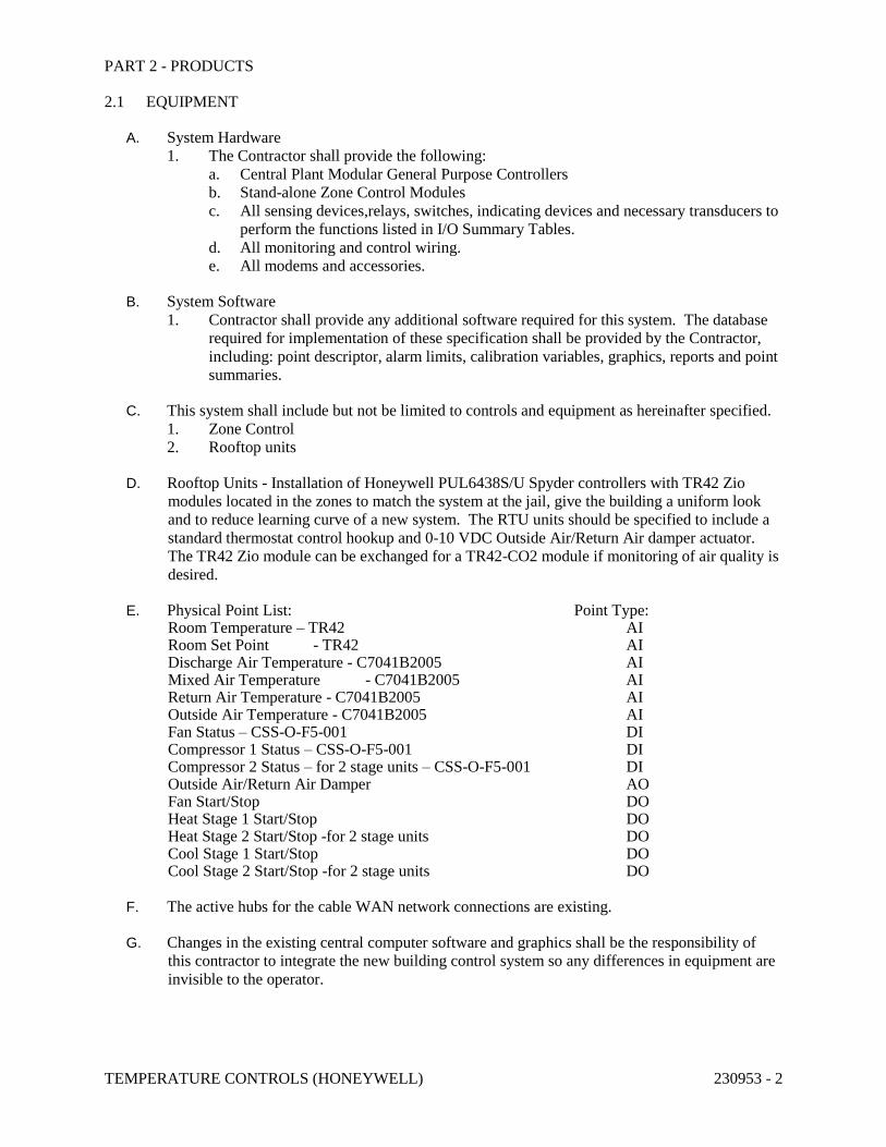
2.1 EQUIPMENT
A. System Hardware
1. The Contractor shall provide the following:
a. Central Plant Modular General Purpose Controllers
b. Stand-alone Zone Control Modules
c. All sensing devices,relays, switches, indicating devices and necessary transducers to
perform the functions listed in I/O Summary Tables.
d. All monitoring and control wiring.
e. All modems and accessories.
B. System Software
1. Contractor shall provide any additional software required for this system. The database
required for implementation of these specification shall be provided by the Contractor,
including: point descriptor, alarm limits, calibration variables, graphics, reports and point
summaries.
C. This system shall include but not be limited to controls and equipment as hereinafter specified.
1. Zone Control
2. Rooftop units
D. Rooftop Units - Installation of Honeywell PUL6438S/U Spyder controllers with TR42 Zio
modules located in the zones to match the system at the jail, give the building a uniform look
and to reduce learning curve of a new system. The RTU units should be specified to include a
standard thermostat control hookup and 0-10 VDC Outside Air/Return Air damper actuator.
The TR42 Zio module can be exchanged for a TR42-CO2 module if monitoring of air quality is
desired.
E. Physical Point List: Point Type: Room Temperature – TR42 AI Room Set Point - TR42 AI Discharge Air Temperature - C7041B2005 AI Mixed Air Temperature - C7041B2005 AI Return Air Temperature - C7041B2005 AI Outside Air Temperature - C7041B2005 AI Fan Status – CSS-O-F5-001 DI Compressor 1 Status – CSS-O-F5-001 DI Compressor 2 Status – for 2 stage units – CSS-O-F5-001 DI Outside Air/Return Air Damper AO Fan Start/Stop DO Heat Stage 1 Start/Stop DO Heat Stage 2 Start/Stop -for 2 stage units DO Cool Stage 1 Start/Stop DO Cool Stage 2 Start/Stop -for 2 stage units DO
F. The active hubs for the cable WAN network connections are existing.
G. Changes in the existing central computer software and graphics shall be the responsibility of
this contractor to integrate the new building control system so any differences in equipment are
invisible to the operator.
TEMPERATURE CONTROLS (HONEYWELL) 230953 - 3
2.2 REFERENCES
A. Codes and Regulations. All electrical equipment and material and its installation shall conform
to the current requirements of the following authorities:
1. Occupational Safety and Health Act (OSHA)
2. National Electric Code (NEC)
3. National Fire Code
4. Uniform Building Code
5. Uniform Mechanical Code
6. Uniform Plumbing Code
B. Note: Where two or more codes conflict, the most restrictive shall apply. Nothing in these plans
and specifications shall be construed to permit work not conforming to applicable codes.
PART 3 - EXECUTION
3.1 WARRANTY AND CORRECTION OF WORK
A. The Contractor shall warrant that all systems, subsystems, component parts, and software are
fully free from defective design, materials, and workmanship for a period of one year from the
date of final acceptance by the Owner. In addition the Contractor shall warranty that all
components and installation conforms to specifications set forth in this bid offering.
1. If, within one year from date of final acceptance of Contract completion, any of the work
is found to be defective or not in accordance with the Contract documents, the Contractor
shall correct it promptly after notification to do so. The Contractor shall bear all cost of
correcting such work.
3.2 COORDINATION DURING CONSTRUCTION
A. The Contractor shall coordinate working schedules with the District to minimize disruption of
the normal facility activities.
PART 4 - SUBMITTALS, DOCUMENTATION, AND ACCEPTANCE
4.1 SUBMITTALS
A. Shop Drawings. A minimum of six (6) copies of shop drawing shall be submitted and shall
consist of complete list of equipment and material, including manufacturer's descriptive and
technical literature, catalog cuts, installation instructions and sequence of control. Shop
drawings shall also contain complete wiring, routing, schematic diagrams, tag number of
devices, software descriptions, calculations, and any other details required to demonstrate that
the system will function properly. Drawings shall show proposed layout and installation of all
equipment and the relationship to other parts of the work.
B. Shop drawings shall be approved before any equipment is installed. Therefore, shop drawings
must be submitted in time for the Engineer's review so that all installations can be completed
per the project's completion schedule. Ten working days shall be allowed for the Engineer to
review submittals.
C. All drawings shall be reviewed after the final system checkouts and updated or corrected to
provide "as-built" drawings to show exact installation. The system will not be considered
complete until the "as-built" drawings have been installed in the M&O Manuals and reviewed
with the Owner during the training process.
D. Before final configuration, the Contractor shall provide I/O Summary forms to the Engineer that
TEMPERATURE CONTROLS (HONEYWELL) 230953 - 4
include:
1. Description of all points.
2. Listing of binary and analog hardware required to interface to the equipment for each
function.
3. Listing of all application programs associated with each piece of equipment.
4. Failure modes for control functions to be performed in case of failure.
E. The Contractor shall provide an accurate graphic flow diagram for each software program
proposed to be used on the project as part of the submittal process. Revisions made as a result
of the submittal process, during the installation, start-up or acceptance portion of the project,
shall be accurately reflected in the "asbuilt" graphic software flow diagrams herein required by
this specification.
F. The Contractor shall be able to simulate the operation of all software application programs to
ensure they are free from design errors and that they accurately accomplish the application
sequence of operations. All software must be thoroughly checked by simulation prior to being
used to operate the District equipment.
4.2 ACCEPTANCE TEST AND ACCEPTANCE
A. Upon completion of the installation, the Contractor shall start up the system and perform all
necessary calibration, testing, and debugging operations. An acceptance test shall be performed
by the Contractor in the presence of the Honeywell representative and the Engineer.
B. When the system performance is deemed satisfactory, the system parts will be accepted for
beneficial use and placed under warranty. At this time the warranty period shall start.
END OF SECTION 230953
NATURAL GAS SYSTEMS 231123 - 1
SECTION 23 1123 – NATURAL GAS SYSTEMS
PART 1 - GENERAL
1.1 RELATED DOCUMENTS
A. Drawings, General Provisions of Contract, including General and Supplementary Conditions
and Section 23 0501 apply to this Section.
1.2 SUMMARY
A. Furnish and install gas piping and fittings within building including connection to meter.
1.3 QUALITY ASSURANCE
A. Qualifications:
1. Welders shall be certified and bear evidence of certification 30 days prior to commencing
work on project. If there is doubt as to proficiency of welder, Owner's Representative
may require welder to take another test. This shall be done at no cost to Owner.
Certification shall be by Pittsburgh Testing Laboratories or other approved authority.
PART 2 - PRODUCTS
2.1 PIPE
A. Meet requirements of ASTM A 53-89a, "Specification for Pipe, Steel, Black & Hot-Dipped
Zinc-Coated Welded & Seamless".
B. Carbon steel, butt welded, Schedule 40 black steel pipe.
2.2 FITTINGS
A. Black Pipe:
1. Welded forged steel fittings meeting requirements of ASTM A 234-89a, "Specification
for Piping Fittings of Wrought Carbon Steel and Alloy Steel for Moderate and Elevated
Temperatures", or standard weight malleable iron screwed.
2.3 VALVES
A. 125 psi bronze body ball valve, UL listed
B. Approved Manufacturers & Models:
1. ConBraCo - "Apollo" series 80-100
2. Jenkins - FIG-30-A
3. Jomar - Model T-204
4. McDonald - 3410
5. PGL Corp - "Red Cap" gas ball valve
6. Watts - Model B-6000-UL
2.4 PRESSURE REDUCING REGULATORS
A. Corrosion Resistant Brass Body.
B. 1/2" to 4" Threaded NPT
NATURAL GAS SYSTEMS 231123 - 2
C. 2" and Above Flanged.
D. Max Inlet Pressure 10 psi.
E. Max Outlet Pressure 0.5 psi.
F. Temperature Capabilities - ~20 to 180° F.
G. Approved Manufactures and Models.
1. Emerson Process Management.
2. Maxitrol 3UP33
3. Or approved equal.
PART 3 - EXECUTION
3.1 INSTALLATION
A. Pipe installed underground, through air plenums, in walls, and pipes 2-1/2 inches and larger
shall have welded fittings and joints. Other pipe may have screwed or welded fittings.
B. Wrap and lay underground pipe in accordance with local gas utility company regulations and
specifications.
C. Install gas cocks on lines serving boilers, furnaces, duct heaters, and water heaters adjacent to
boiler, furnace, or heater on outside of boiler, furnace, or heater cabinet and easily accessible.
D. Do not use flexible pipe connections to boilers, furnaces, duct heaters, or hot water heaters.
E. Install dirt leg with pipe cap, 6 inches long minimum, on each vertical gas drop to heating
equipment.
F. Use fittings for changes of direction in pipe and for branch runouts.
G. Paint exterior exposed gas piping with grey paint to match gas meter.
END OF SECTION 231123
LOW-PRESSURE STEEL DUCTWORK 233114 - 1
SECTION 233114 - LOW-PRESSURE STEEL DUCTWORK
PART 1 - GENERAL
1.1 RELATED DOCUMENTS
A. Drawings, General Provisions of Contract, including General and Supplementary Conditions
and Section 23 0501 apply to this Section.
1.2 SUMMARY
A. Furnish and install above-grade ductwork and related items as described in Contract
Documents.
PART 2 - PRODUCTS
2.1 DUCTS
A. Fabricate of zinc-coated lockforming quality steel sheets meeting requirements of ASTM
653A/653M, "Specification for Sheet Steel Zinc-Coated (Galvanized) by the Hot-Dip Process,
Lock Forming Quality", with G 60 coating.
B. Use of aluminum, non-metallic, or round ducts is not permitted. [Specification writer: Use of
aluminum ducts in areas with high chlorine content (eg.: ventilation for pools, spas, etc.) should
be considered on a per job basis.]
2.2 DUCT JOINTS
A. Ducts with sides up to and including 36 inches shall be as detailed in the SMACNA manual.
B. Duct sizes over 36 inches shall be fabricated using SMACNA T-24 flange joints or pre-
fabricated systems as follows:
1. Ducts with sides over 36 inches to 48 inches:
a. transverse duct joint system by Ductmate/25, Nexus, Ward, or WDCI (Lite)
(SMACNA "E" or "G" Type connection).
2. Ducts 48 inches & larger:
a. Ductmate/35, Nexus, or WDCI (Heavy) (SMACNA "J" Type connection).
3. Approved Manufacturers:
a. Ductmate Industries Inc, 10760 Bay Meadows Drive, Sandy, UT 84092 (801) 571-
5308
b. Nexus, Exanno Corp, P O Box 729, Buffalo, NY 14206 (716) 849-0545
c. Ward Industries Inc, 1661 Lebanon Church Road, Pittsburg, PA 15236 (800) 466-
9374
d. WDCI, P O Box 10868, Pittsburg, PA 15236 (800) 245-3188
2.3 ACCESS DOORS IN DUCTS
A. At each manual outside air damper and at each motorized damper, install factory built insulated
access door with hinges and sash locks. Locate doors within 6 inches of installed dampers.
Construction shall be galvanized sheet metal, 24 ga minimum.
B. Fire and smoke damper access doors shall have a minimum clear opening of 12" x 12" or as
specified on Drawings to easily service fire or smoke damper. Doors shall be within 6 inches of
fire and smoke dampers and in Mechanical Room if possible.
LOW-PRESSURE STEEL DUCTWORK 233114 - 2
C. Identify each door with 1/2" high letters reading “smoke damper” or “fire damper”.
D. Approved Manufacturers:
1. AirBalance - Fire/Seal #FSA 100
2. Air Control Products - HAD-10
3. Cesco-Advanced Air - HAD-10
4. Elgen - Model 85 A
5. Kees Inc - ADH-D.
6. Louvers & Dampers - #SMD-G-F
7. Nailor-Hart Industries Inc - Series 0831
8. National Controlled Air Inc - Model AD-FL-1
2.4 FLEXIBLE EQUIPMENT CONNECTIONS
A. 30 oz closely woven UL approved glass fabric, double coated with neoprene.
B. Fire retardant, waterproof, air-tight, resistant to acids and grease, and withstand constant
temperatures of 250 deg F.
C. Approved Manufacturers:
1. Cain - N-100
2. Duro Dyne - MFN
3. Elgen - ZLN
4. Ventfabrics - Ventglas
2.5 CONCEALED CEILING DAMPER REGULATORS
A. Approved Manufacturers:
1. Cain
2. Duro Dyne
3. Metco Inc
4. Vent-Lock - #666
5. Young - #303
2.6 VOLUME DAMPERS
A. In Main Ducts:
1. 16 gauge galvanized steel, opposed blade type with 3/8 inch pins and end bearings.
Blades shall have 1/8 inch clearance all around.
2. Damper shall operate within acoustical duct liner.
3. Provide channel spacer equal to thickness of duct liner.
4. Approved Manufacturers:
a. Air Balance - Model AC-2
b. Air Control Products - CD-OB
c. American Warming - VC-2-AA
d. Greenheck - VCD-1100
e. NCA, Safe Air
f. Vent Products - 5100
B. In Sheet Metal Branch Ducts:
1. Extruded aluminum, opposed blade type. When in open position, shall not extend
beyond damper frame.
2. Maximum blade length 12 inches.
LOW-PRESSURE STEEL DUCTWORK 233114 - 3
3. Damper Regulator shall be concealed type with operation from bottom or with 90 deg
miter gear assembly from side.
4. Approved Manufacturers:
a. Air Control Products - TCD-OB
b. Air Guide - OB
c. Arrow - OBDAF-207
d. CESCO - CDA
e. Reliable Metals - OBD-RO
f. Tuttle & Bailey - A7RDDM
g. Safe Air
h. Young - 820-AC
C. Dampers above removable ceiling and in Mechanical Rooms shall have locking quadrant on
bottom or side of duct. Otherwise, provide concealed ceiling damper regulator and cover plate.
2.7 DUCT HANGERS
A. 1" x 18 gauge galvanized steel straps or steel rods as shown on Drawings, and spaced not more
than 8 feet apart. Do not use wire hangers.
B. Attaching screws at trusses shall be 1-1/2 inch No. 10 round head wood screws. Nails not
allowed.
2.8 DUCT SEALER
A. Cain - Duct Butter or Butter Tak
B. Design Polymerics - DP 1010
C. DSC - Stretch Coat
D. Duro Dyne - S2
E. Hardcast - #601 Iron-Grip or Peel-N-Seal Tape
1. Kingco - 15-325
2. Mon-Eco - 44-41
3. Trans-Continental Equipment Co - Multipurpose Duct Sealant
4. United - Sheet Metal duct-sealer
PART 3 - EXECUTION
3.1 INSTALLATION
A. Ducts:
1. Straight and smooth on inside with joints neatly finished unless otherwise directed.
2. Duct panels through 48 inch dimension having acoustic duct liner need not be
crossbroken or beaded.
3. Crossbreak unlined ducts and duct panels larger than 48 inch or bead 12 inches on center.
4. Securely anchor ducts to building structure with specified duct hangers attached with
screws. Do not hang more than one duct from a duct hanger.
5. Brace and install ducts so they shall be free of vibration under all conditions of operation.
6. Ducts shall not bear on top of structural members.
7. Make duct take-offs to branches, registers, grilles, and diffusers as detailed on Drawings.
LOW-PRESSURE STEEL DUCTWORK 233114 - 4
8. Ducts shall be large enough to accommodate inside acoustic duct liner. Dimensions
shown on Drawings are net clear inside dimensions after duct liner has been installed.
9. Properly flash where ducts protrude above roof.
10. Install internal ends of slip joints in direction of flow. Make joints air tight using
specified duct sealer.
11. Cover horizontal and longitudinal joints on exterior ducts with two layers of Hardcast
tape installed with Hardcast HC-20 adhesive according to Manufacturer's
recommendations.
12. Paint ductwork visible through registers, grilles, and diffusers flat black.
B. Install flexible inlet and outlet duct connections to each furnace, fan, fan coil unit, and air
handling unit.
C. Install concealed ceiling damper regulators.
1. Paint cover plates to match ceiling tile.
2. Damper regulators will not be required for dampers located directly above removable
ceilings or in Mechanical Rooms.
D. Provide each take-off with an adjustable volume damper to balance that branch.
1. Anchor dampers securely to duct.
2. Install dampers in main ducts within insulation.
3. Dampers in branch ducts shall fit against sheet metal walls, bottom and top of duct, and
be securely fastened. Cut duct liner to allow damper to fit against sheet metal.
4. Where concealed ceiling damper regulators are installed, provide a cover plate.
E. Install grilles, registers, and diffusers. Level floor registers and anchor securely into floor.
F. Air Turns:
1. Permanently installed, consisting of single thickness curved metal blades with one inch
straight trailing edge to permit air to make abrupt turn without appreciable turbulence, in
90 degree elbows of above ground supply and return ductwork.
2. 4-1/2 inch wide minimum vane rail. Do not use junior vane rails.
3. Double thickness vanes not acceptable.
4. Quiet and free from vibration when system is in operation. See SMACNA Manual
END OF SECTION 233114
FLEX DUCT 233346 - 1
SECTION 233346 - FLEX DUCT
PART 1 - GENERAL
1.1 RELATED DOCUMENTS
A. Drawings, General Provisions of Contract, including General and Supplementary Conditions
and Section 23 0501 apply to this Section.
1.2 SUMMARY
A. Furnish and install supply air branch duct runouts to diffusers as described in Contract
Documents.
PART 2 - PRODUCTS
2.1 DUCTS
A. Formable, flexible, circular duct which shall retain its cross-section, shape, rigidity, and shall
not restrict air flow after bending.
B. Nominal 1-1/2 inches thick, 3/4 lb/cu ft density fiberglass insulation with air-tight, polyehtylene
or polyester core, sheathed in seamless vapor barrier jacket factory installed over flexible
assembly.
C. Assembly, including insulation and vapor barrier, shall meet Class I requirement of NFPA 90A
and be UL 181 rated, with flame spread of 25 or less and smoke developed rating of 50 or
under.
D. Length of flexible ductwork shall not exceed 8'-0".
2.2 APPROVED MANUFACTURERS
A. ANCO-FLEX - 4625
B. Flex-Aire - PF/UPC #090
C. Hart & Cooley - F114
D. Thermaflex - G-KM
PART 3 - EXECUTION
3.1 INSTALLATION
A. Install duct in fully extended condition free of sags and kinks.
B. Make duct connections by coating exterior of duct collar for 3 inches with duct sealer and
securing duct in place over sheet metal collar with 1/2 inch wide metal cinch bands and sheet
metal screws.
END OF SECTION 233346
AIR OUTLETS & INLETS 233713 - 1
SECTION 233713 - AIR OUTLETS & INLETS
PART 1 - GENERAL
1.1 RELATED DOCUMENTS
A. Drawings, General Provisions of Contract, including General and Supplementary Conditions
and Section 23 0501 apply to this Section.
1.2 SUMMARY
A. Furnish and install wall supply registers, transfer grilles, return air grilles, soffit grilles, ceiling
diffusers, louvers connected to ductwork, and registers as described in Contract Documents.
PART 2 - PRODUCTS
2.1 GRILLES & REGISTERS
A. Approved Manufacturers:
1. Price
2. Anemostat
3. Krueger
4. Titus
5. Tuttle & Bailey
2.2 SPIN-IN FITTINGS
A. Low pressure round take-offs to diffusers shall be made with spin-in fittings. They shall
incorporate a manual balancing damper. The damper shall be spring loaded and a positive
locking wing nut shall secure the damper position.
PART 3 - EXECUTION
3.1 INSTALLATION
A. Anchor securely into openings.
B. Install with screws to match color and finish of grilles and registers.
C. Touch-up any scratched finish surfaces.
D. Install in accordance with manufacturer's instructions.
E. Check location of outlets and inlets and make necessary adjustments in position to conform with
architectural features, symmetry, and lighting arrangement.
F. Install diffusers to ductwork with air tight connection.
G. Provide balancing dampers on duct take-off to diffusers, and grilles and registers, despite
whether dampers are specified as part of the diffuser, or grille and register assembly.
H. Paint ductwork visible behind air outlets and inlets matte black. Refer to Section 09 9000.
END OF SECTION 233713
DISPOSABLE FILTERS 234100 - 1
SECTION 234100 – DISPOSABLE FILTERS
PART 1 - GENERAL
1.1 RELATED DOCUMENTS
A. Drawings, General Provisions of Contract, including General and Supplementary Conditions
and Section 23 0501 apply to this Section.
1.2 SUMMARY
A. Furnish and install filters used in mechanical equipment.
PART 2 - PRODUCTS
2.1 AIR HANDLING UNIT FILTERS
A. 2 inch thick, medium efficiency, disposable type pre-formed pleated design, having at least 4.5
sq ft of filtering media per sq ft of face area.
B. Media shall be reinforced non-woven cotton fabric, treated with adhesive similar to "Vyclad B"
and continuously laminated to supporting steel wire grid conforming to configuration of pleats.
C. Media pack shall be sealed in a chipboard frame or beverage board.
D. Filters shall have rated average efficiency of 25 to 30% on ASHRAE Test Standard 52-76 and
be capable of operating with variable face velocities up to 500 FPM without impairing
efficiency.
E. Initial resistance shall not exceed 0.30 inches w.g. at 500 FPM or 0.14 inch w.g. at 300 FPM.
Filter shall be listed Class 2 by UL.
F. Approved Manufacturers:
1. Type 30/30 by Farr Co
2. Mark 80 by Serv-Aire
3. HC Type 40 by Envopleat
4. DP2-40 by Air Guard
END OF SECTION 234100
ROOFTOP HEATING-COOLING UNIT 236220 - 1
SECTION 236220 – ROOFTOP HEATING-COOLING UNIT
PART 1 - GENERAL
1.1 RELATED DOCUMENTS
A. Drawings, General Provisions of Contract, including General and Supplementary Conditions
and Section 23 0501 apply to this Section.
1.2 QUALITY ASSURANCE
A. Unit shall be AGA certified.
1.3 WARRANTY
A. Provide five-year warranty on compressors.
PART 2 - PRODUCTS
2.1 MANUFACTURED UNITS
A. Unit shall be one piece combination air-to-air DX mechanical cooling system and gas fired
heating system complete with automatic controls.
B. Equipment shall be shipped completely assembled, pre-charged, piped and wired internally
ready for field connections.
C. Roof mounting frame shall be furnished and installed. Frame shall be steel and mate to bottom
perimeter of equipment. When flashed into roof, it shall make a unit mounting curb and
provide weather-proof duct connection and entry into conditioning area.
D. Power Saver: (Fresh Air Dampers)
1. Provide complete with all controls and air mixing damper assembly, including fresh air,
recirculated air, and exhaust air dampers.
2. Fresh air section shall be equipped with air filters.
3. Mixing box sections shall contain low leakage dampers with edge seals and inflatable
blade seals.
E. Cooling System:
1. Coils shall be non-ferrous construction with aluminum fins mechanically bonded to
seamless copper tubes.
2. Condenser coil shall have sub-cooling rows.
3. Compressor shall be resiliently mounted, have built-in 3-mode crankshaft lubrication,
crankcase heater, discharge temperature limiter, current and temperature sensing motor
overloads.
4. Cooling system shall be protected by high and low pressure switches and compressor
timed off control.
5. Provide with hail guard over condenser coil.
F. Heating System:
1. Automatic controls furnished to give 50/50 2-stage operation.
2. Cylindrical tube and drum exchanger constructed of Duraglas coated steel or stainless
steel.
3. Stainless steel burner listed for operation at low outdoor air temperatures.
ROOFTOP HEATING-COOLING UNIT 236220 - 2
4. Visual inspection of burner flame possible through observation port at rear of heat
exchanger.
5. Power vented.
G. Air Movers:
1. Twin centrifugal conditioned air blowers with permanently lubricated ball bearings,
adjustable belt drive or direct drive as shown on drawings.
2. Condenser fans shall be direct driven.
3. Motors shall have inherent protection devices.
H. Frame and Casing:
1. Frame shall be welded construction.
2. Casing shall be galvanized panels with baked-on outdoor enamel finish.
3. Entire cabinet shall be insulated with 1" thick fiberglass.
4. Provide coil guards on exposed condenser coils.
I. Furnish two sets of 2" throw away filters.
J. Approved Manufacturers:
1. Lennox
2. Trane
3. Carrier
4. York
PART 3 - EXECUTION
3.1 FIELD QUALITY CONTROL
A. Provide manufacturer's startup and warranty.
END OF SECTION 236220
END OF DIVISION 23