Embed Size (px)
Citation preview
DIY balancing. I hope that the main articles on the theory behind engine balance have removed the mystic which often surrounds this subject. In fact there is no reason why anyone, with enough mechanical aptitude to assemble an engine, cannot achieve good results with some home grown balancing on certain types of engine. The only equipment necessary being a set of scales and a means of crankshaft support that allows for free low friction rotation. Traditionally, the scales were the balance beam type most often seen in chemistry lessons at school. However, modern electronic scales with digital readout have largely replaced those. Scales with a maximum capacity of 1 kg. and resolution of 1g. will do very well for most motorcycle engine balancing. Generally, one of three methods of supporting the crankshaft is used.
1. Parallel rails. 2. Overlapping rollers. 3. Centres – either in a dedicated holding stand or in a lathe.
Parallel rails are illustrated in fig.1. Although simple to make, their alignment is critical. They must be parallel and horizontal in both lateral and longitudinal directions to a high standard. Those shown use a circular profile but best results are obtained with the working surface hardened and ground to a blunt knife edge shape to reduce friction. Rails should only be used with crankshafts that have identical main shaft diameters on each side, otherwise the crank will want to follow a curved path and some extra friction will be introduced.
Fig. 1. Using parallel rails to check balance. In this case the rails are circular in section, the inset shows an alternative cross sectional shape preferred by the author, to reduce friction. The narrow support area demands that these rails need to hardened and ground for best results, whereas the round section would work well for occasional use without hardening. Parallelism and horizontal alignment of the rails is important to achieve accurate results.
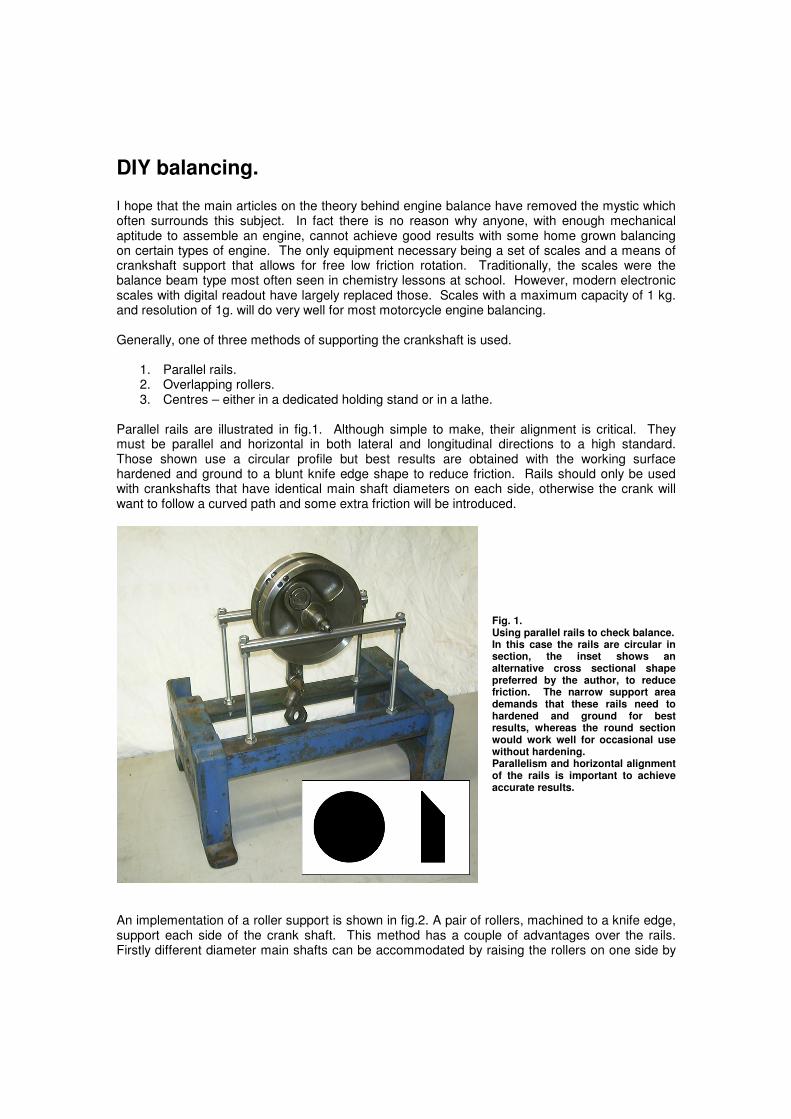
An implementation of a roller support is shown in fig.2. A pair of rollers, machined to a knife edge, support each side of the crank shaft. This method has a couple of advantages over the rails. Firstly different diameter main shafts can be accommodated by raising the rollers on one side by
the difference in main shaft radii. Secondly, it only has one axis that needs to be aligned horizontally and that is less critical than with the rails.
Fig. 2. A pair of roller discs are used to support each side of the crankshaft. The inset shows more detail of the roller support. Note also the centre holes drilled in the ends of the main-shafts.
Most crankshafts have tapered centre holes drilled in each main shaft, which can be seen in fig. 2. Therefore, the crankshaft can be supported with two lathe centres. Such centres are available in solid form and what is known as rolling centres. The rolling centres are best for our task because friction is reduced. This method has the advantage that if you already have access to a lathe then the scales are the only other piece of equipment needed. The disadvantages are that friction is likely to be higher and for large crankshafts there may not be enough room above the lathe bed to clear the dangling conrod and weights. We have seen that there are two classes of balance to consider – static and dynamic. Without a proper balancing machine it is not really feasible to consider DIY dynamic balancing and this is best left to those with the experience and equipment. We have seen that when we balance an engine we do it to a certain “balance factor” which balances a percentage of the primary reciprocating force at TDC. However we can only do this statically with a limited number of engine types. Single cylinder, 360° vertical twins and V-twins being suitable. Other types, for example, boxer engines and 180° twins can be in static balance with any value of balance factor and so we cannot statically balance this type to a specified factor. These have to be done on a normal dynamic balancing machine.
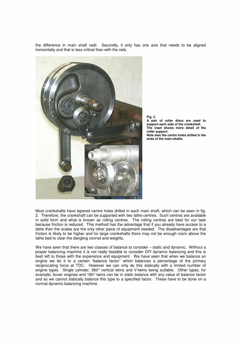
To achieve a given balance factor we must balance 100% of the rotating parts of the big-end and conrod as well as the specified percentage of the reciprocating components. Therefore we need some extra mass opposite the crank pin or less mass on the crankpin side of the flywheels. This effect can be achieved in any number of ways as shown in fig. 3. Another less common way is to make the flywheels eccentric with respect to the main-shafts as illustrated in fig. 4. This is a crank made by Greg Summerton of South Australia for an Eso speedway engine. It is clear that the flywheels are not concentric with the crankcase housing. There are several holes drilled and tapped around the periphery to allow fine tuning of the balance factor. The degree of eccentricity is calculated with half of these holes filled with grub screws, this allows adjustment to be made to increase or decrease the balance factor and to adjust for different weight pistons.
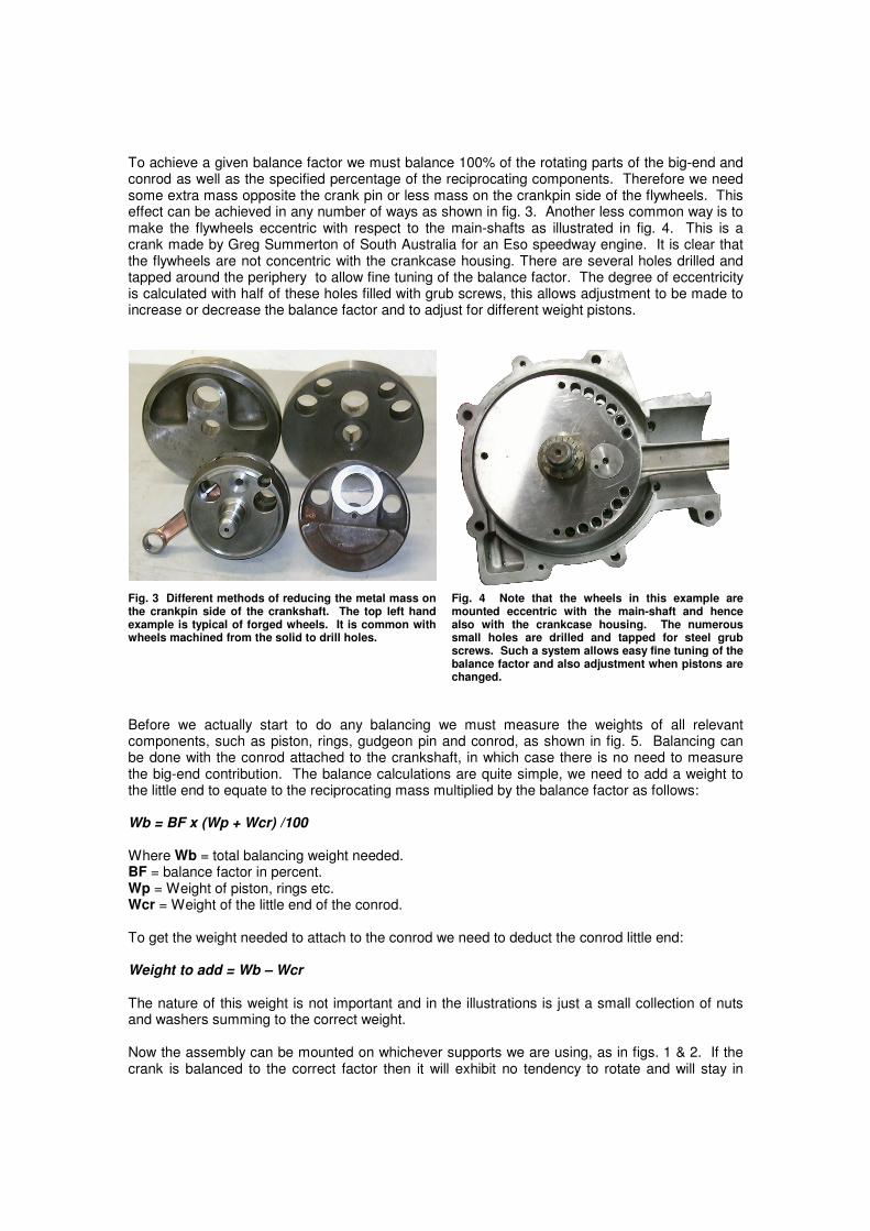
Fig. 3 Different methods of reducing the metal mass on the crankpin side of the crankshaft. The top left hand example is typical of forged wheels. It is common with wheels machined from the solid to drill holes.
Fig. 4 Note that the wheels in this example are mounted eccentric with the main-shaft and hence also with the crankcase housing. The numerous small holes are drilled and tapped for steel grub screws. Such a system allows easy fine tuning of the balance factor and also adjustment when pistons are changed.
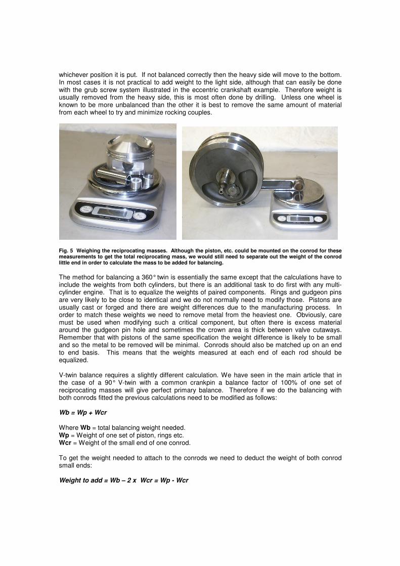
Before we actually start to do any balancing we must measure the weights of all relevant components, such as piston, rings, gudgeon pin and conrod, as shown in fig. 5. Balancing can be done with the conrod attached to the crankshaft, in which case there is no need to measure the big-end contribution. The balance calculations are quite simple, we need to add a weight to the little end to equate to the reciprocating mass multiplied by the balance factor as follows: Wb = BF x (Wp + Wcr) /100 Where Wb = total balancing weight needed. BF = balance factor in percent. Wp = Weight of piston, rings etc. Wcr = Weight of the little end of the conrod. To get the weight needed to attach to the conrod we need to deduct the conrod little end: Weight to add = Wb – Wcr
The nature of this weight is not important and in the illustrations is just a small collection of nuts and washers summing to the correct weight. Now the assembly can be mounted on whichever supports we are using, as in figs. 1 & 2. If the crank is balanced to the correct factor then it will exhibit no tendency to rotate and will stay in
whichever position it is put. If not balanced correctly then the heavy side will move to the bottom. In most cases it is not practical to add weight to the light side, although that can easily be done with the grub screw system illustrated in the eccentric crankshaft example. Therefore weight is usually removed from the heavy side, this is most often done by drilling. Unless one wheel is known to be more unbalanced than the other it is best to remove the same amount of material from each wheel to try and minimize rocking couples.
Fig. 5 Weighing the reciprocating masses. Although the piston, etc. could be mounted on the conrod for these measurements to get the total reciprocating mass, we would still need to separate out the weight of the conrod little end in order to calculate the mass to be added for balancing.
The method for balancing a 360° twin is essentially the same except that the calculations have to include the weights from both cylinders, but there is an additional task to do first with any multi-cylinder engine. That is to equalize the weights of paired components. Rings and gudgeon pins are very likely to be close to identical and we do not normally need to modify those. Pistons are usually cast or forged and there are weight differences due to the manufacturing process. In order to match these weights we need to remove metal from the heaviest one. Obviously, care must be used when modifying such a critical component, but often there is excess material around the gudgeon pin hole and sometimes the crown area is thick between valve cutaways. Remember that with pistons of the same specification the weight difference is likely to be small and so the metal to be removed will be minimal. Conrods should also be matched up on an end to end basis. This means that the weights measured at each end of each rod should be equalized. V-twin balance requires a slightly different calculation. We have seen in the main article that in the case of a 90° V-twin with a common crankpin a balance factor of 100% of one set of reciprocating masses will give perfect primary balance. Therefore if we do the balancing with both conrods fitted the previous calculations need to be modified as follows: Wb = Wp + Wcr
Where Wb = total balancing weight needed. Wp = Weight of one set of piston, rings etc. Wcr = Weight of the small end of one conrod. To get the weight needed to attach to the conrods we need to deduct the weight of both conrod small ends: Weight to add = Wb – 2 x Wcr = Wp - Wcr
Other than that the procedure is exactly the same as with the single cylinder machine. We have seen that non 90° V-twins can have perfect primary balance with staggered crankpins for each cylinder. The main article gives a formula and graph for deciding on the optimal balance factor. The offset of the crankpins introduces a slight additional complication to the calculation of the mass to be added to the little end to check the balance, as follows: Wb = BF x (Wp + Wcr) /100 Where Wb = total balancing weight needed. BF = balance factor in percent. Wp = Weight of one set of piston, rings etc. Wcr = Weight of the small end of one conrod. To get the weight needed to attach to each conrod we need to account for the stagger of the pins:
Weight to add = 0.5 x (Wb – Wcr) / cos(θθθθ/2)
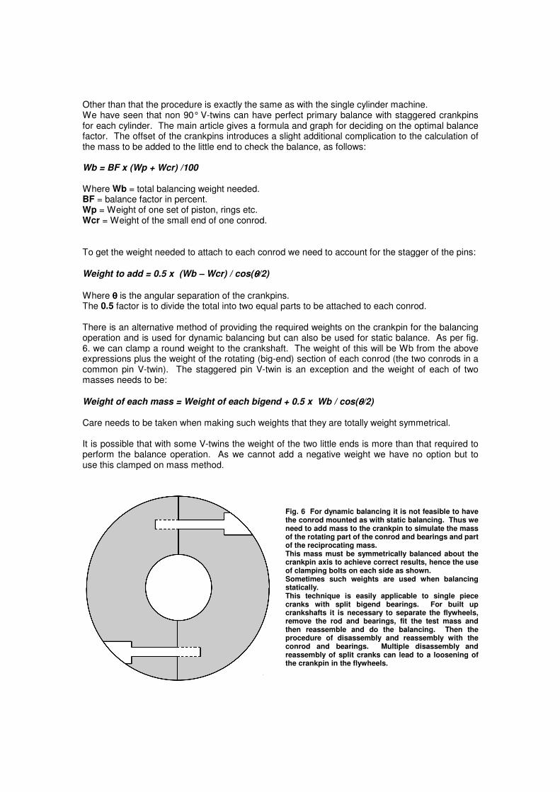
Where θθθθ is the angular separation of the crankpins. The 0.5 factor is to divide the total into two equal parts to be attached to each conrod. There is an alternative method of providing the required weights on the crankpin for the balancing operation and is used for dynamic balancing but can also be used for static balance. As per fig. 6. we can clamp a round weight to the crankshaft. The weight of this will be Wb from the above expressions plus the weight of the rotating (big-end) section of each conrod (the two conrods in a common pin V-twin). The staggered pin V-twin is an exception and the weight of each of two masses needs to be:
Weight of each mass = Weight of each bigend + 0.5 x Wb / cos(θθθθ/2) Care needs to be taken when making such weights that they are totally weight symmetrical. It is possible that with some V-twins the weight of the two little ends is more than that required to perform the balance operation. As we cannot add a negative weight we have no option but to use this clamped on mass method.
Fig. 6 For dynamic balancing it is not feasible to have the conrod mounted as with static balancing. Thus we need to add mass to the crankpin to simulate the mass of the rotating part of the conrod and bearings and part of the reciprocating mass. This mass must be symmetrically balanced about the crankpin axis to achieve correct results, hence the use of clamping bolts on each side as shown. Sometimes such weights are used when balancing statically. This technique is easily applicable to single piece cranks with split bigend bearings. For built up crankshafts it is necessary to separate the flywheels, remove the rod and bearings, fit the test mass and then reassemble and do the balancing. Then the procedure of disassembly and reassembly with the conrod and bearings. Multiple disassembly and reassembly of split cranks can lead to a loosening of the crankpin in the flywheels.
Except for the 90° common pin V-twin where we aim for a 100% factor, or staggered pin V-twins where we can calculate an optimal factor, the biggest problem with balancing other types of engine is deciding what factor to aim for. In the end this usually has to be done by experiment or experience. Even then we may find that a given engine and frame combination will be smoothest with different balance factors at different RPM. Hence the best factor to use will depend on how the engine is used. As mentioned earlier there are many types of engine that we can’t balance by a static method and long shafts really need proper dynamic balance anyway. In such cases we need to use the services of a specialist, however, those who enjoy doing as much of their own work as possible can probably save some money by matching piston and conrod weights before going to the balance shop. Foot note: Special thanks are due to Greg Summerton who took time out to set up and photograph his equipment for the benefit of this article.