Embed Size (px)
Citation preview

© 4 Ris0-R-923(EN)
DK9700006
Reliability and radiationtolerance of robotsfor nuclear applicationsKurt Lauridsen, Ris0 National Laboratory, DenmarkMarc Decreton, SCK • CEN, BelgiumClaudia-Christina Seifert, Siemens AG, GermanyRichard E. Sharp, AEA Technology, United Kingdom
i^AEA
SIEMENS
D.
Ris0 National Laboratory, Roskilde, DenmarkOctober 1996
VOL 2

Reliability and radiationtolerance of robotsfor nuclear applications
Kurt Lauridsen, Ris0 National Laboratory, DenmarkMarc Decreton, SCK-CEN, BelgiumClaudia-Christina Seifert, Siemens AG, GermanyRichard E. Sharp, AEA Technology, United Kingdom
Ris0 National Laboratory, Roskilde, DenmarkOctober 1996
Abstract The reliability of a robot for nuclear applications will be affected by environ-mental factors such as dust, water, vibrations, heat, and, in particular, ionising radiation. Thepresent report describes the work carried out in a project addressing the reliability andradiation tolerance of such robots.
A widely representative range of components and materials have been radiation tested and thetest results has been collated in a database along with data provided by the participants fromearlier work and data acquired from other sources. A radiation effects guide has been writtenfor the use by designers of electronic equipment for robots. A generic reliability model hasbeen set up together with generic failure strategies, forming the basis for specific reliabilitymodelling carried out in other projects. Modelling tools have been examined and developedfor the prediction of the performance of electronic circuits subjected to radiation. Reports havebeen produced dealing with the prediction and detection of upcoming failures in electronicsystems.
Operational experience from the use of robots in radiation work in various contexts has beencompiled in a report, and another report has been written on cost/benefit considerations aboutthe use of robots. Also the possible impact of robots on the safety of the surrounding planthas been considered and reported.
The present report is an edited version of the final report for the CEC/TELEMAN projectNo. FI2T-CT90-0011, ENTOREL.
ISBN 87-550-2219-7
ISSN 0106-2840
Grafisk Service, Ris0 1996

Contents
Introduction 5
The ENTOREL project team 6
Work carried out on individual tasks 6Task 1: Definition of work scope 6Task 2: Database 7Task 3: Testing 10
Task 3.1 Electronic Components, High Power 11Task 3.2 Electronic Components, Low Power 12Task 3.3 Sensor systems 14Task 3.4 Multiplexing and communication systems 19Task 3.5 Vision systems 20Task 3.6 Materials 21Task 3.7 Radiation testing of a selected group of subsystems 23
Task 4: Radiation effects guidelines 23Task 5: Simulation of faulty electronic circuits 23Task 6: Reliability models 25Task 7: Development of failure strategies 27Task 8: Coordination 29Task 9: Gathering of external data 29Task 10: Dissemination of data to other TELEMAN projects 31Task 11: Assessment of the performance of TELEMAN prototype machines in a
radiation environment 31Task 12: Robots and plant safety 32Task 13: Cost-benefit investigation of the use of robots 32Task 14: Formulation of testing strategies 32Task 15: Fault detection and prediction 32Task 16: Gathering of operational experience with robots 33
Project meetings 33
Conference participation relevant to the project, and related publications 33
Exploitation of the results of the project 33
General experience 34
Acknowledgements 35
Literature 35Internal project reports 36Conference papers and other publications 39Non-ENTOREL references 45Student theses relevant to ENTOREL 45
Ris0-R-923(EN) 3

Contact points to the ENTOREL partners 46
Figures 47
Appendix A: Participating staff from each partner 63
Appendix B: List of data sets in the database 65
Ris0-R-923(EN)

Introduction
From 1990 to 1996 the European Commission ran a research programme, TELEMAN, withthe aim to develop robots for use in radiation environments, in particular with a view to thenuclear power industry. A total of 21 projects were run under TELEMAN, related to develop-ment of components and subsystems, and designing and building test machines. An importantpart of the programme was the study of reliability and radiation tolerance. One of the projects,ENTOREL, was devoted to these subjects in general and, in addition, the subjects wereintegral parts of three of the other projects. The present report describes the results of theENTOREL project.
The reliability of a "TELEMAN machine" will be affected by environmental factors such asdust, water, vibrations, heat, and ionising radiation. The effects of many of these factors onthe components and materials in question were well known prior to TELEMAN, butknowledge was missing about the effects of large doses of ionising radiation (=106 Gy) whichwere relevant here. Furthermore, there was a need to establish knowledge at system level, i.e.about complete TELEMAN machines. Components and materials which are especiallysusceptible to radiation damage are: electronics, sensors, fibre optics, signal communicationsystems, insulating materials, lubricants, and adhesives.
In order to assess how much the various factors influence the reliability, the project was toprovide data as well as models for the calculation of the reliability of TELEMAN machinesas a function of time and exposure. Furthermore, failure strategies were to be developed toplan the difficult task of recovery of a stranded machine. Reliability data already existing withthe partners and elsewhere for relevant equipment were to be collated in a data base. Possiblegaps in the existing data were to be covered by component or materials testing. Concurrently,reliability models as well as other models for the assessment of the behaviour of the machinewere to be set up. A very important part of the work throughout the project was to be thecollection of data and other information from external (to TELEMAN) sources and thedissemination of this information as well as information generated by the project to thepartners of all the TELEMAN projects. Procedures to detect emerging radiation inducedfailures at an early stage were to be proposed, based on knowledge about failure mechanismsin materials and electronic systems. By literature studies and contacts to robot operatorsoperational experience with robots was to be collected with a view to assessing the benefitsand drawbacks in the use of robots.
Ris0-R-923(EN)

The ENTOREL project team
The ENTOREL project had four contractors: Ris0 National Laboratory (Denmark,coordinator), SCK»CEN, Mol (Belgium), Siemens Energieerzeugung KWU (former Interatom)(Germany), and AEA Technology - Harwell Laboratory (UK) (the AEA group participatingin ENTOREL now resides at the Culham laboratory). In addition, three subcontractors havebeen active during the project, the IMEC laboratory of Leuven, Belgium, RadiationExperiments and Monitors (REM) of Oxford, England, and Roger Home, RHC, France.Furthermore, Spur Electron Ltd., England, under a special study contract has producedsoftware for the import of data from the European Space Agency.
In addition, most of the ENTOREL partners have taken part in other TELEMAN projects.This gave the project good contacts to the TELEMAN community, enabling it to direct itswork towards the needs of the machine-building projects, and at the same time gather datafrom these projects for inclusion in the ENTOREL database.
Work carried out on individual tasks
In the following, the work performed and results achieved are described task by task, usingthe task numbers defined in the project's Technical Annex. Some of the tasks were carriedout by one partner alone, others had more than one partner working on them. Where possible,the description below gives an indication of which work was carried out by which partner.
Task 1: Definition of work scope.The first part of the whole programme was the preparation of a document defining its scope
and the types of equipment and components most in need of environmental/safety/reliability
assessment This document also provided rather more detail of the environmental conditions
being considered for TELEMAN machines in order to enable the ENTOREL participants to
tailor their testing programmes to yield relevant and useful data.
The report [1] was issued during the first year of the project. Three classes of machine wereoutlined: a mobile vehicle for inspection, monitoring and intervention purposes in low tomoderate radiation environments; a gantry-based manipulator for operational and maintenancetasks in high radiation environments; and a long reach device for internal pipe work in lowradiation environments. The list of tasks and duties for each of these machines has enableda preliminary assessment to be made of the likely requirements in terms of components witha relatively low radiation tolerance, i.e. sensors, on-board intelligence or some materials. Inturn, this assessment helped to shape and define the direction of further work packages withinthe programme.
6 Ris0-R-923(EN)

The report then considered each of the other tasks in detail, describing the aim of each and
the end result, be it a report, a computer programme or some other result. Finally, a copy of
the ENTOREL technical annex was included for reference purposes.
In addition to the work mentioned above, SCK»CEN carried out a preliminary review of
different typical nuclear situations, especially relevant to PWR (normal operation and
dismantling tasks) in order to define the environmental conditions [2,3,105].
With regard to the identification of equipment and components most in need of environmentaltolerance-, safety-, and reliability assessment Siemens prepared a report on the Criteria for theSelection of Components for Irradiation Tests within the TELEMAN Project [4]. These cri-teria are related to sensor systems being relevant to the three types of the conceptualmanipulators for TELEMAN.
The work scope was extended when the project was extended into the second phase of
TELEMAN. This change was reflected in the revised Technical Annex.
In addition, a certain effort was put into amending the scope of the project in 1993/94 inorder to cater for possible inclusion of possible new partners under the EC's PECOprogramme for cooperation in science and technology with central and eastern Europeancountries and with new independent states of the former Soviet Union. ENTOREL was amongthe three projects under the Nuclear Safety Programme which were mentioned in PECO'sinformation material as projects where partners from the above countries could apply forparticipation. This led to requests from some 30 companies and institutes, resulting in anapplication to PECO for support to the inclusion of five new partners from Lithuania,Hungary, the Slovak Republic, Russia and Poland. In order to comply with the conditions setout by PECO, the contributions of the new partners had to be additional features to the scopeof the project. Most of the work in formulating the additions and the application was carriedout by the coordinator. As it turned out, no funding was granted to the applicants toENTOREL, and the effort had been more or less in vain.
Task 2: Database.The purpose of this task was to modify and amend a database of radiation effects in electroniccomponents which already existed at Siemens (then Interatom). Originally the task had threesubtasks, "Modify existing database", "Upgrading gathered information" and "Update database". As the work progressed it turned out to be impractical to make a distinction. Therefore,the work is described under one heading below. It also turned out that the effort needed toadapt the database to the needs of TELEMAN was substantially larger than originallyanticipated. This, unfortunately, is a rather frequent phenomenon for software projects.Furthermore, the version changes of the commercial software used has given rise to someinconvenience as well.
Ris0-R-923(EN) 7

As a first step, the requirements for the ENTOREL database were analyzed and assessed,leading to the overall structure of the database, shown in Figure 1. This structure wasprogrammed and adjusted to the formerly existing database at Siemens/In teratom. The threepartners carrying out testing (Siemens, SCK»CEN and AEA Technology) had different formatsfor storing the test results. Therefore, in order to accommodate the test data from thesedifferent sources, some data input routines had to be written; this also turned out to be rathertime consuming, both for Siemens and the other partners who were not originally assumedto spend manpower on the database task. At an early stage it was decided to put the highestpriority to the entry of data for electronic components rather than materials, because thematerials data seemed difficult to handle in the database format at hand.
In 1991 an agreement of exchange of data was made with the European Space Agency (ESA)and ESA made its radiation effects database available to ENTOREL. This database containsmany data which are not so interesting seen from a TELEMAN point of view, e.g. data foreffects from heavy particles which are only met in space. But it also contains many data forthe effects of y-radiation on electronic components which are of interest in nuclearapplications. Since the ESA database has a completely different data structure, compared tothe ENTOREL database, the feasibility of constructing data transfer software had to beconsidered thoroughly. This feasibility study was carried out by Spur Electron Limited [5]with an extensive collaboration by Siemens. Spur is the company that runs and maintains thedatabase for ESA. The study showed the general possibility for automatic transfer of totaldose data from the ESA/ESTEC database to the ENTOREL database system. Automatic datatransfer was chosen, in particular with a view to future, not yet available, ESA-data.
The feasibility study and the following construction of the data transfer software wereperformed under separate CEC study contracts to Spur Electron. To accept data from the ESAdatabase transfer programme, written by Spur, an interface-system adapted to the ENTORELdatabase was written by Siemens. A characteristic scheme to sort out TELEMAN irrelevantdata from the ESA data was elaborated by Siemens who also specified which total dose datashould be transferred. After the different pieces of software had been completed, the relevantESA data were transferred to the ENTOREL database.
In order to record the degree of confidence in the data entered into the ENTOREL databasethree validation categories (high confidence, some confidence, low confidence) were definedby the partners [6]. The validation "marks" given by the persons entering the data into thedatabase later on was tested by an independent validation of part of the data sets fromdifferent contributors [7, 8]. Samples were selected for validation with a slight view to"dubious looks", and some had to be degraded in classification because some formalrequirements were not met; but, in general, the data were deemed to be of good quality.
Ris0-R-923(EN)

The final version of the ENTOREL-database by the end of the project contains more than 600data sets, including all tests performed by AEA Technology, SCK>CEN and Siemens as partof the project. Furthermore, the above mentioned ESA data are included, as well as dataprovided by the partners from other sources, e.g. the Fusion research programme. The ESAdata were produced by the test houses CNES, HMI and MBB. The database provides steadystate, total dose radiation test data. It gathers results of total dose tests performed onelectronic components in the Mega Gray dose ranges of gamma radiation. The database holdsmore than 40 device subclasses, 250 different device types and about 60 manufacturers.Additional 38 records on literature relevant to the tests are provided. A list of the data setsin the database is supplied in appendix A. Some of the data may not be freely available, butthe database will hold information about their existence and a reference to the source.
The database now exists in a fully operational PC-version which has been installed at each
partner site. The use of the database is to a large extent self-explanatory, but is supported by
a user's manual [9]. The database is suitable for selecting devices during the design stage of
robotics and remote systems for nuclear environments.
The user application of the ENTOREL-Database is distributed as a PC runtime version of aread-only database. With more than 600 tests gathered, its size is about 17 MB. The databasemanagement system is DataEase 4.2, and the graphics programme used is GRAFTALK 5.0.
All information is accessible on the one hand by overview tables, referring to e.g. devicesubclasses, device types or manufacturers, and on the other hand by different query paths, asthere are requested device subclasses, requested device types and requested manufacturers.All of the requests may be carried out with a request or without a request for an indicationof threshold values. The term threshold value here represents a value of accumulated dosewhere a defined degradation of a component takes place.
The data in this database refer to discrete components such as diodes, transistors (bipolar,FET) as well as to integrated circuits like amplifiers, comparators, multiplexers, micropro-cessors and others as fibre optic cables, force sensors and inclination sensors.
The tests cover a range of maximum accumulated dose from 2-103 to 1107 Gy (Si) withrespective dose rates of 0.27-103 to 3.3-107 Gy(Si)/h and a maximum accumulated dose fromHO3 to 1106Gy(H2O) with respective dose rates from 0.085-103 to 11.4-103Gy(H2O)/h. Mainquery paths in the ENTOREL-database are the views of threshold values and parameterdependence of device subclasses, device types and manufacturers.
Queries result in data output of lists with device data (device classes, device types,technology, manufacturers), piecepart identification (lot number, serial number, date ofmanufacture), test data (test facility, test identification, test conditions, number of samples),
Ris0-R-923(EN) 9

measurement data (parameters, bias conditions, temperature, damage criteria), radiation data(total dose, dose rate, threshold value, annealing) and quality assurance (data validation, datasources, comments on data). In addition, tables of measurement data for mean-, max- andmin-values for device parameters may be looked up and the same values are given in agraphical presentation according to the relevant query. The whole structure of the ENTOREL-Database is shown in Figure 1 [62].
Two guides for installation of the ENTOREL-database's runtime version have been provided[10, 11]. In order to make the ENTOREL-Database known to the public and interested parties,papers have been prepared for national and international conferences [126,131 and 121]. Oneof these efforts to make the ENTOREL-database known resulted in the interest of the FloridaUniversity (USA) to take data from the ENTOREL-Database on to the WWW (World WideWeb).
After the completion of the ENTOREL project the database will be maintained and distributed
by one of the ENTOREL partners.
Task 3: Testing.Task 3 involves the radiation tolerance assessment of components and subsystems considered
susceptible to the effects of radiation. Work on this task was carried out by three of the
project partners, AEA Technology, SCK»CEN and Siemens.
The choice of items to be tested in the first part of the project was made based mainly on theexperience of the partners with respect to components and materials used in already existingrobot systems. In addition, advice about which sensors and materials to test was sought fromother TELEMAN contractors by means of a questionnaire [52], mentioned later.
The technical annex divides Task 3 into the seven subtasks, listed below.
3.1 Testing of high power electronic components
3.2 Testing of low power electronic components
3.3 Testing of sensor systems
3.4 Testing of multiplexing and communications systems3.5 Testing of vision systems
3.6 Testing of materials
3.7 Testing of a selected group of subsystems
Within the first six areas, lists of relevant tests already performed were set up before plans
for testing were prepared. As a special exercise within this task, comparative tests were
performed of a few selected components by all three testing partners. The main reason for
carrying out these common tests was to show what differences exist due to the partners'
10 Ris0-R-923(EN)

different methods of testing, thus enabling them to compare their other results. The tests
concerned small-signal transistors and their results are described in more detail under task 3.2.
As the work progressed the distribution of activities on the above mentioned subtasks betweenthe testing partners was changed somewhat compared to the original planning set out in theTechnical Annex. This fact reflected the change in priorities among component types and -for the part of Siemens - the lack of irradiation facility when the Jiilich reactor they wereusing closed. However, the total effort put into task 3 was close to the planned one.
Task 3.1 Electronic Components, High Power. The assessment of radiation effects on fourtypes of power bipolar transistor, five types of power diode and seven types of powerMOSFETs has been carried out in both Co-60 and spent fuel radiation environments.
Parameters measured were as follows, with data being obtained before irradiation and
at seven increasing stages of total integrated dose (1,3, 10, 30, 100, 300 and 1,000
kGy):
Power bipolars: forward current gain
saturation voltage (VCE(slt))
breakdown voltage (BVCB0)
leakage current
Power MOSFETs: gate threshold voltage (VGS(th))gate leakage current (IGSS)
drain-source breakdown voltage (BVDSS)
Power diodes: forward voltage (VF)reverse breakdown voltage (V(BR)R)reverse leakage current (IR).
Results were much as expected with a fall in gain, increase in saturation voltage andbreakdown voltage and a small rise in leakage current for the bipolar transistors, an increasein threshold voltage, leakage current and breakdown voltage for the MOSFETs; and very littlechange in any parameters for the power diodes.
In addition, some measurements have been carried out on power bipolar transistors in orderto characterise the nature of radiation-induced defects on a microscopic scale. These haveincluded deep level transient spectroscopy (DLTS) and forward and reverse transit timemeasurements. All measurements have been made before and after each of a series ofincreasing total integrated gamma radiation doses and a total of four device types has beenstudied.
Ris0-R-923(EN) 11
The work provided detailed information on the effects of radiation on these components,covering total integrated doses across the whole range of interest to TELEMAN. Differencesbetween the effects caused by the two different radiation environments have been shown tobe negligible.
This subtask was carried out by AEA solely.
Task 3.2 Electronic Components, Low Power. All three testing partners were active onthis subtask. At an early stage of the project the comparative tests, mentioned above, werecarried out. These tests were performed on four device types, all small signal bipolartransistors: BC108 (NPN, metal can), 2N3704 (NPN, plastic package), BCY70 (PNP, metalcan) and 2N3906 (PNP, plastic package). To assure homogeneity in the devices tested,devices from the same batches have been used for the tests. Siemens used a spent fuelirradiation facility (up to 0.8 MGy at up to 500 Gy/h) for the tests [12]. At SCK»CEN thetransistors were tested up to a total dose of 300 kGy at a rate of 300 Gy/h using Co-60sources. They were tested as part of the RIT-1 irradiation described under Task 3.3[13,14,15]. At a later stage SCK»CEN performed further irradiation of the transistors up toa total dose of 830 kGy [16]. At Harwell testing took place in a Co-60 irradiation cell (up to1 MGy at 10.5 kGy/h) [17], and periodic re-testing of the transistors took place in order toassess the annealing of radiation effects.
A comparison of the obtained results showed some slight differences due to the measuringconditions, dose rates and energy spectrum. In general, a good consistency was observedbetween transistor types and experimental sites. Both for the amplification factor hFE (Figure2) and for the saturation voltage Vce(sat) (Figure 3), some variation of degradation speedcould be observed along the dose build-up, with even slight recovery in some cases. This canbe due to the different mechanisms responsible for degradation and changes in their relativeimportance with time. Figure 4 from the Harwell tests illustrates the spread in results for hFEfor 15 transistors of the same type tested simultaneously. A detailed discussion of thecommon tests was published in the International Journal on Microelectronics and Reliability[110]. Furthermore, comparisons are reported by Siemens and Harwell in separate reports[18,19], and a paper [118] was presented at the RADECS'93 conference in St. Malo, France.
Apart from the common tests, many other tests were carried out.
At Harwell, component types examined under this heading have included small-signal bipolartransistors, signal- and zener diodes, i.e. the fundamental semiconductor components of anyelectronic circuit. A comparison of the effects of radiation from cobalt-60 and spent fuel hasalso been carried out for these components. This yielded similar results to those found inWP3.1, i.e. that the differences between the two environments did not lead to significantlydifferent effects in the devices.
12 Ris0-R-923(EN)

A further assessment covered four types of operational amplifier and four types of comparator[20,21]. Some examples of these components were found to be suitable for operation in activeenvironments. Their use would permit significant reductions in the size and number of cablespenetrating cell walls and would make mobile operation of equipment possible. Figure 5shows the results of measurements of one parameter for two device types.
Richard Sharp from Harwell carried out a thorough study of the published literature relating
to radiation effects on bipolar devices and silicon samples, in conjunction with the Ris0
National Laboratory programme for visiting scientists. This covered work published over the
last 45 years, dealing with gamma, beta and neutron radiation effects on bulk silicon samples,
bipolar test structures, discrete bipolar devices and bipolar integrated circuits. The aim of the
study was to attempt to identify any underlying properties which are easily measurable and
also direct indicators of the radiation tolerance of a device before any exposure to radiation
has taken place.
At Harwell, furthermore, the usability of pMOS dosimeters at total integrated doses between1 kGy and 1 MGy was examined. This work was part funded by other sources. Two typesof dosimeter were included in the trials, one from REM and the other from NMRC. Further-more, the REM type was tested in two different package styles. Irradiation was carried outat two widely separated dose rates, 13.6 kGy/h and 85 Gy/h, to a series of total integrateddose stages. Irradiation data sheets presenting the results obtained to date have been issued[22].
Also at Harwell, a comparison of the effects of radiation on devices packaged in bothstandard and surface mount versions has been made for three pairs of bipolar transistors [23].This showed that within the limits of accuracy of the measurements (generally 15% or better),no significant differences between the two styles of packaging were discernable. A papersummarising this work was published at the RADECS'95 conference [149].
For Siemens' tests, spent fuel was used as the gamma source where the mean energy as wellas the decay characteristic was measured and calculated exactly. The tests were carried outin accordance with the ESA/SCC Basic Specification No. 22900 and MIL STD-883C, Method1019.2. To cater for constant measuring values current sources were used for power supplyto keep the current conditions very stable, and a four-wire technique was used to minimizeerrors resulting from voltage drops over contact points and cabling. For each device typemeasured (bipolar transistors and linear ICs) a special technique was developed makingallowance for a manual measurement of the single parameters. An automatic test equipmentmay in some cases, where temperature or electrical effects impact the measured device, giveerroneous results. In addition to the common tests, described above, operational amplifiers(Type TAA 765A, LM 741 CH, TBA 222 BS1, MAX 400 CPA) were tested up to 580 kGy.Static and dynamic parameters were measured in accordance to the experience and results
Ris0-R-923(EN) 13

gained from the common tests. Some devices turned out to be suitable for the application ina high radiation environment. The test results are evaluated and reported in [24].
Task 3.3 Sensor systems. The main part of the work at this task was done by SCK«CEN.
At the outset, particular attention was given to a review of typical sensors with respect to their
radiation hardening availability. The sensors considered were:ultrasonic proximeters (capacitive and piezoelectric types)
inductive proximeterscapacitive proximetersLVDT contact sensors
tactile sensorsinfrared proximity switches
encoders and resolvers
Industrially available position sensors were evaluated and in some instances procured.Laboratory tests were conducted prior to real environment testing. Particular attention wasgiven to their constitutive materials, their tolerance to degradation and their reliability [106].
In addition, it was decided to assess the needs of all the TELEMAN participants in terms oftheir sensor requirements. The vast range of different types of sensor means that any arbitrarychoice made by the ENTOREL team alone is less likely to be relevant than a choice basedupon the individual project needs. To this end, a questionnaire requesting information on thetypes of sensor intended for use was prepared and circulated to all TELEMAN participants[25]. This yielded several replies, although there was little consistency between them. Thereplies, summarised in [26], led to the selection of two types of inductive proximity detectorfor radiation testing in order to give indicative results for the programme.
Testing at SCK«CEN took place in two different facilities, the CMF spent BR2-fuel facility,where a series of experiments called GASTAFIORE took place, and the RITA Co-60 facility,where experiments in the RIT- series were carried out. Some of the tests were funded in partor fully by other research programmes, such as the European Fusion Technology programmeor the Dismantling programme. The following tests were performed and the results enteredinto the ENTOREL database.
Irradiation test GASTAFIORE IIThis gamma irradiation test contained the following items:
Seven optical fibres, six of them being monitored on-line
One inductive proximity sensor
One capacitive sensorThree ultrasonic sensorsTwo multiplexer designs (monitored on line)
14 Ris0-R-923(EN)

Four types of relays (monitored on line)
The radiation dose rate was 20 kGy/h, and the test was performed up to a maximum totaldose of 10 MGy. The results, detailed in [27], showed that carefully chosen fibre optics,inductive and ultrasonic sensors can be used at the highest levels of radiation specified forthe TELEMAN machines. The tolerant design of multiplexing circuit was also found to befeasible at these levels [28,103].
Irradiation test GASTAFIORE VIIThis experiment was performed in 5 irradiation campaigns, at a dose rate of 20 kGy/h,leading to a total dose of 10 MGy. Targets were ultrasonic sensors, potentiometers andinclinometers. The following specimens were tested:
Penny & Giles (UK) Inclinometer: radiation hardened potentiometer based tilt sensor,
specified to at least 1 MGy by manufacturer.Penny & Giles (UK) Potentiometer: radiation hardened rotary potentiometer,
specified up to a total dose of 1 MGy by manufacturer.Pewatron (Switzerland) Inclinometer: accelerometer type tilt sensor.Pewatron(Switzerland) Potentiometer: rotary potentiometer.
MicroMeasurement (USA) strain gauge: K-alloy and constantan fully encapsulated
strain gauges.Sensy Loadcell (Belgium): 500 N radiation hardened load cell.MuRata (Japan) ultrasonic transducers: piezoelectric ultrasonic transducers.
The tests, performed also partially for the fusion programme, show that the Penny & Gilesinclinometer did not reach the total dose specified by the manufacturer: after the secondirradiation campaign, at a total dose of 0.5 MGy, the sensor was jammed, due to solidificationof the damping liquid.
The Penny & Giles potentiometer showed no significant degradation up to a total dose of2.7 MGy, which was reached after the 4th irradiation campaign. After the 5th irradiationcampaign, at a total dose of 7 MGy, the potentiometer did not operate any more. Postirradiation examination revealed that corrosion, probably from gas releases of the plastic partsof the sensor, damaged the thin leads from the potentiometer resistor to the contact pins,outside the potentiometer.
The Pewatron inclinometers showed a relatively good behaviour up to a total dose of 7 MGy.The output range of the sensor slightly decreases, and a decalibration was observed. Thelinearity of the sensor remained good.
The Pewatron potentiometers only showed a small decrease in output range up to a total dose
of 7 MGy. At this dose an increased friction of the bearings was observed. After the last
Ris0-R-923(EN) 15

irradiation campaign, at a total dose of 10 MGy, the friction of the bearings was so high thatit was impossible to turn the potentiometer without breaking it.
The strain gauges showed no significant degradation in sensitivity and performance. Special
attention has to be put however on the soldering pads to connect the instrumentation wire to
the gauges. When small pads are used, they tend to come loose easily with possible damage
to the strain gauge.
The load cell shows a large offset (150 %) at 10 MGy, but remains linear. The electroniccontrol unit allows for compensation of this offset, and hence the loadcell can provide forcemeasurements up to 10 MGy total dose, when regular compensation of the offset is done.
The ultrasonic transducers showed a decrease in sensitivity and sound pressure level of up to50 dB. This, however, did not influence the distance measuring capabilities of the sensorsystem built around these transducers. The maximum detectable distance decreased from 4m down to 2.5 m, but the system still allows to measure a distance ranging from 30 cm to2.5 m with a 2 % accuracy. A dedicated electronic circuit was built to allow remote operationwith long cables between the transducer and the electronic control circuit: tests with cablelength of up to 30 m showed no degradation in performance.
Irradiation test RIT-1
This experiment was performed in six irradiation campaigns, up to a total dose of 300 kGy,at a rate of 350 Gy/h [29,30]. The targets were the following :
Two types of piezoelectric ultrasonic sensorsOne capacitive sensor
Light Emitting Diodes, phototransistors and photodiodesTransistors, as part of the common ENTOREL test described under Task 3.2Tactile force sensors, one of which coming from a complementary TELEMANproject (TM-18, Univ. Brussels)Two optical fibres including their connectors.
The experiment showed that piezoelectric ultrasonic transducers are well suited for nuclearoperations at least up to a dose of 300 kGy. The tests on optoelectronics showed aperformance decrease, in particular the optical output power of light emitting diodes and theoptical sensitivity of photodiodes and phototransistors, but no failure. The components are stilloperational at 200 kGy and their degraded performance can be eventually compensated by aproper circuit design. A decrease of 15 dB is for instance observed at this dose. Allcomponents show a particular dependency on irradiation and biasing history (Figure 6)[29,30].
16 Ris0-R-923(EN)

Tactile sensors, based on variable resistance of polymers have been shown to be operationalup to at least 250 kGy, and offer a good solution for contact detection. Tactile sensors basedon optical measurement of polymer dimensional changes (in collaboration with TELEMANproject TM18) showed a good behaviour of the polymer (stable elasticity), but improvementof the optoelectronic parts is required to achieve sufficient radiation tolerance.
The experiment confirmed the good results obtained for optical fibres focusing on mechanicalresistance of cabling material, buffer and coating, up to 300 kGy, and radiation tolerance ofconnectors.
Irradiation test RIT-2
The RIT-2 experiment was performed in six irradiation subcampaigns, up to a total dose of300 kGy at a dose rate of 300 Gy/h [16]. The following targets were tested :
capacitive proximity sensor
optical fibre couplers and optical fibre switches
one resolver type absolute encoder.some targets already irradiated in RIT-1 [30] : bipolar transistors (see Task 3.2),
ultrasonic sensors, two types of optical fibres, a tactile sensor.
Irradiation test RIT-3
The RIT-3 experiment was performed in six irradiation subcampaigns, up to a total dose of
300 kGy at a dose rate of 270 Gy/h [31,32]. The following targets were tested :
two types of capacitive transducer ((one already irradiated in RIT-2 [16])one visible laser dioderadiation hardened optoelectronic components, to compare their behaviour with the
not resistant counterparts, as irradiated in RIT-1 [30]
several RADFETs (dosimeters), provided by REMsome targets already irradiated during the previous campaigns (bipolar transistors aspart of the common ENTOREL test described under Task 3.2, one type ofpiezoelectric transducer, a prototype of optical fibre proximity switch, two types ofoptical fibres, optical fibre couplers and switches, a resolver).radiation resistant multiplexing circuits (cf. Task 3.4)
The results obtained in RIT-2 and RIT-3 can be summarised as follows.
Piezoelectric ultrasonic transducers are well suited for nuclear operations, at least up todose of 730 kGy. Particular attention should be put on the materials used for any acousticimpedance matching and acoustic focusing, since standard polymers become too brittle.
Ris0-R-923(EN) 17

A commercial capacitive transducer has been identified, without observable degradation withrespect to sensing distance and linearity. Another capacitive transducer shows smalldegradation with increasing dose and a decrease of hysteresis up to 220 kGy.
The experiment confirmed the results obtained for optical fibres with respect to attenuation.Mechanical strength of the fibre depends on the radiation resistance of buffer and coating, andinteraction with corrosive gases can damage the surface of the fibre at the connector side.
Fibre optics switches and couplers show relative good results: radiation induced attenuationand functionality remain within tolerable limits up to 300 kGy. For higher total doses, thecorrosion of the fibre surface at the connector side gives rise to an attenuation which exceeds50%.
The tactile force sensors show a decrease in sensitivity for higher total dose, but still remain
usable for contact detection.
The resolver type absolute encoder did not undergo any noticeable degradation with respectto repeatability and resolution, and this up to at least 480 kGy.
The visible laser diode showed no optical output at a total dose of 0.8 kGy.
Radiation resistant optoelectronic components prove to show better performances than theirstandard counterparts [30]. The degradation is smaller and stabilizes at a total dose of 100kGy. Bias conditions and presence of radiation also have less influence (Figure 7).
The results on RADFETs have been analyzed by REM [33]. They show the applicability ofRADFETs for on-line monitoring of doses on a nuclear manipulator.
Irradiation test RIT-4
This experiment was carried out in nine irradiation campaigns. Campaign number 1 to 8 wereconducted at a low dose rate (22 Gy/h), leading to a total dose of 15 kGy. Campaign number9 was conducted at a dose rate of 267 Gy/h, up to a total dose of 34 kGy. The followingtargets were tested:
three types of strain gauges,
one special design force-torque sensor,
one rad-hard design 500 N loadcell.
The tests showed that the strain gauges keep a very good behaviour up to the specified totaldose. The zero reference shift varies from 1 pe up to 12 ue, and the response to applied forceschanges less than 1% before and after the irradiation. A custom designed force-torque robotwrist sensor was provided by JR3 (USA). The sensor showed no noticeable degradation up
18 Ris0-R-923(EN)
to a total dose of 34 kGy. A radiation hardened load cell, provided by Sensy (Belgium),proved to show no degradation at all up to 30 kGy.
Finally, at SCK»CEN an experiment was performed on optical fibre with partial support fromthe ENTOREL project. It was focused on the use of fibres in the visible spectrum forfibroscopy. A special Russian fibre with aluminium coating and very low OH and Cl contentin the silica core has shown to be very resistant in the visible spectrum, up to 1.5 MGy. Theoptical degradation shows a quick levelling-off and this hardening phenomenon is anticipatedto continue up to the higher doses.
At Harwell, two types of inductive proximity detector have been tested. Irradiation test reportshave been issued for both types [34, 35]. Very different behaviour was observed to occur inthe two types of detector. One type showed complete failure after a total integrated dose ofonly 3 kGy, while the other type all continued to function, albeit with a slight rise inswitching distance, to a total dose of 1 MGy.
Task 3.4 Multiplexing and communication systems. Work on this task was performed bySCK«CEN alone.
Communication between sensors and control unit needs specific links that must be chosencarefully in order to ensure their environmental resistance and their operational practicality.The following aspects have been studied:
cable connection
• radiation hardened cables• radiation hardened optical fibres and connectorsResults of experiments reported under WP 3.3 showed the feasibility of optical linksup to high doses,multiplexing capabilities• analogue remote switch designed for high radiation doses. A tolerant design of
multiplexer circuits using standard components has been made and tested inrepresentative environment. The feasibility of this approach was demonstrated andpublished [28,103].
• an analysis of available rad-hard integrated circuits, and their integration in aprototype multiplexing circuit including Analogue to Digital Conversion was carriedout and tests performed as part of the RIT-3 experiment [36]. The tests show thatall components failed at total doses lower than indicated in the manufacturer's datasheets. The analog devices (the analog multiplexer and the analogue-to-digitalconverter) proved to be more sensitive to radiation (failure between 1 and 2 kGy)than the digital components (the latch and the parallel in/serial out register), whichfailed at about 3 kGy.
• rad hard optical time domain multiplexing
Ris0-R-923(EN) 19
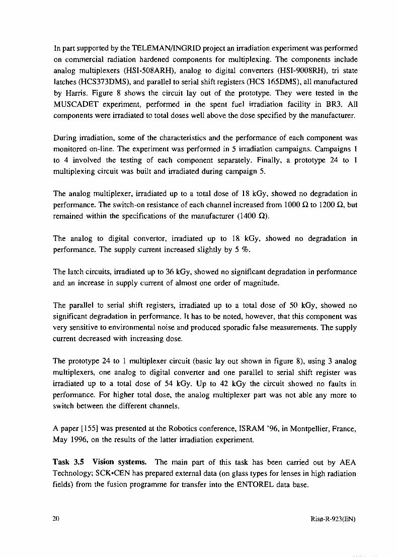
In part supported by the TELEMAN/INGRID project an irradiation experiment was performedon commercial radiation hardened components for multiplexing. The components includeanalog multiplexers (HSI-508ARH), analog to digital converters (HSI-9008RH), tri statelatches (HCS373DMS), and parallel to serial shift registers (HCS 165DMS), all manufacturedby Harris. Figure 8 shows the circuit lay out of the prototype. They were tested in theMUSCADET experiment, performed in the spent fuel irradiation facility in BR3. Allcomponents were irradiated to total doses well above the dose specified by the manufacturer.
During irradiation, some of the characteristics and the performance of each component wasmonitored on-line. The experiment was performed in 5 irradiation campaigns. Campaigns 1to 4 involved the testing of each component separately. Finally, a prototype 24 to 1multiplexing circuit was built and irradiated during campaign 5.
The analog multiplexer, irradiated up to a total dose of 18 kGy, showed no degradation in
performance. The switch-on resistance of each channel increased from 1000 Q to 1200 Q, but
remained within the specifications of the manufacturer (1400 Q).
The analog to digital convertor, irradiated up to 18 kGy, showed no degradation in
performance. The supply current increased slightly by 5 %.
The latch circuits, irradiated up to 36 kGy, showed no significant degradation in performanceand an increase in supply current of almost one order of magnitude.
The parallel to serial shift registers, irradiated up to a total dose of 50 kGy, showed nosignificant degradation in performance. It has to be noted, however, that this component wasvery sensitive to environmental noise and produced sporadic false measurements. The supplycurrent decreased with increasing dose.
The prototype 24 to 1 multiplexer circuit (basic lay out shown in figure 8), using 3 analogmultiplexers, one analog to digital converter and one parallel to serial shift register wasirradiated up to a total dose of 54 kGy. Up to 42 kGy the circuit showed no faults inperformance. For higher total dose, the analog multiplexer part was not able any more toswitch between the different channels.
A paper [155] was presented at the Robotics conference, ISRAM '96, in Montpellier, France,
May 1996, on the results of the latter irradiation experiment.
Task 3.5 Vision systems. The main part of this task has been carried out by AEATechnology; SCK»CEN has prepared external data (on glass types for lenses in high radiationfields) from the fusion programme for transfer into the ENTOREL data base.
20 Ris0-R-923(EN)

At the outset of the project, a review of equipment standards and test procedures for the doserate and total dose radiation tolerance assessment of CCTV cameras was carried out. As aresult, dose rate radiation testing over six levels can now be completed in one hour, ratherthan two days, as previously (see Figure 9). The procedure permits data capture by videorecording, still photography (35 mm), digital frame stored images, vectorscope images (forcolour cameras) and oscilloscope waveforms. All measurements are carried out undercomputer control, allowing efficient 24-hour operation. The procedure also restricts the totaldose uptake of the camera during dose rate testing to about 5 Gy, allowing total dose testingto commence from a realistic "zero". A poster paper describing this work was presented atthe First European Conference on Radiations and their effects on Devices and Systems,RADECS-91 at Montpellier [101]. Furthermore, another paper [112] relating to the radiationtolerance assessment of CCTV cameras was presented at the BNES conference on RemoteTechniques for Nuclear Plant conference in Stratford, UK in May 1993. A third paper [116],relating to the modelling of radiation effects on CCTV cameras was presented at theInstitution of Nuclear Engineers conference on Modelling and Simulation for the NuclearIndustry in Glasgow in September 1993.
One example of a monochrome, CCD-based camera has been radiation tested [37]. Thiscamera (a Panasonic WV-BL200) was tested according to the standard Radiation TestingService procedure [112], incorporating both dose rate and total dose assessments, in a cobaltcell at Harwell. The highest dose rate at which this camera gave an acceptable picture wasabout 270 Gy/h. At higher dose rates, there was sufficient "snow" on the image to render itunusable for most tasks. For tasks requiring fine detail and high resolution, a lower dose ratelimit would be appropriate. The sensor used in this camera was of the line transfer type andso the picture deteriorated in the usual fashion, with a reduction in charge transfer efficiencybecoming apparent by "smearing" of the image. The degree of smearing had progressed tosuch an extent that the picture was judged unusable after a total integrated dose of 600 Gy.This figure is marginally lower than for some other, typical CCD-based cameras but, as onlyone example was tested, a suitable margin of error should be applied to the results.
Task 3.6 Materials. This task was approached in the same manner as Task 3.3, by aquestionnaire [38]. Rather fewer replies were received regarding materials but, again, thesehave been summarised [26]. At Harwell it was judged that no irradiations were feasiblebecause of the difficulty in choosing materials that would be used on TELEMAN machines.Published data has indicated the extreme variations that can arise in organic materials,depending on the precise composition of the material, the temperature, dose rate andatmospheric conditions. Thus, results from one manufacturer's particular material could bearno relation whatsoever to those for a second manufacturer of nominally the same material.This variation has been shown to be up to three orders of magnitude of total dose. Therefore,work at Harwell was restricted to an awareness exercise, indicating the problems that can
Ris0-R-923(EN) 21

arise. In addition, a standard procedure for radiation testing of organic materials incorporatingthe provisions of the IEC-544 [201] was set up with a view to testing for other customers.
Some tests on organic material samples have, nevertheless, been carried out by AEA
Technology in conjunction with other irradiations. These have included circuit board
materials, cable and wire insulation and adhesives.
Circuit board materials examined include glass fibre, synthetic resin bonded paper (SRBP) andsynthetic resin bonded fibre (SRBF). All three of these survived intact up to a total integratedgamma radiation dose of 1 MGy, although the SRBP had started to lose some of itsmechanical strength at this point. SRBP is not recommended for applications requiring 1 MGyover periods longer than a few weeks.
Cable and wire insulation has been tested where used as power or signal leads for otherexperiments. Materials covered include PEEK, PVC and polyurethane. All of these surviveto 1 MGy under non-oxidative conditions, i.e. at dose rates greater than 1 kGy/h. However,the PVC emits hydrogen chloride which hydrolyses to yield hydrochloric acid, causingcorrosion of surfaces in contact with the material and of the material itself. Under oxidativeconditions, mechanical failure would be expected after about 10 kGy and the hydrogenchloride problem still occurs. PVC is not recommended for applications requiring a radiationtolerance of greater than 10 kGy or for time periods of more than six months in a radioactiveenvironment. Polyether-based polyurethane survives well up to 1 MGy. Polyester-basedpolyurethane also survives to 1 MGy under dry conditions but will not exceed 10 kGy in thepresence of water as it readily undergoes radiation-induced hydrolysis. PEEK survives up toand beyond 1 MGy under all conditions but is rather stiffer than the other materialsmentioned.
At SCK»CEN some irradiation tests were conducted on polymers as parts of tactile sensors,as reported under Task 3.3. Furthermore, selected electrical cables were tested. The selectionwas based mainly on the insulation material: halogen free insulation materials were chosenas well as materials that are known for their inherent radiation resistance, such as polyimide(Kapton) and PEEK. The irradiation was performed in several irradiation campaigns.Irradiation was performed in inert atmosphere (NJ at a dose rate of 20 kGy/h and an ambienttemperature of 50°C up to a total dose of 40 MGy. Further irradiation continued at a dose rateof 5 kGy/h and a temperature of 30°C, up to the total dose of 60 MGy. The cables wereregularly bent during irradiation to simulate dynamic operating conditions in manipulator use.The results confirm the data obtained in static conditions for the selected polymers: no majordegradation of Kapton and PEEK insulation material has been observed.
In addition, external data (on radiation and chemical resistance of O-rings, sealing materials,
insulation, etc) were transferred to the ENTOREL data base by SCK'CEN. These tests
22 Ris0-R-923(EN)

identify materials undergoing only small radiation induced loss of elasticity, with no
correlation between radiation and acid interaction. Silicone O-rings, on the other hand, tend
to harden quickly, and even in an accelerated way in the presence of acids.
Task 3.7 Radiation testing of a selected group of subsystems. This task was added as partof the extension of ENTOREL into phase 2 of TELEMAN with a view to testing subsystemsspecific to the test machines designed during this phase. Accordingly, contacts were taken toother TELEMAN partners in order to identify testing needs of specific subsystems. Thisinvolved the gamma camera in TELEMAN project TM45 (Ciemat), the LACWAP project(ATNutech) and the ROBUG in project (Portech). However, the preliminary contacts did notlead to a real test with samples provided by external partners. The reason was considered tobe mainly the lack of any TELEMAN continuation beyond phase 2. But the contacts showedthat some subsystems are critical to achieve large scale installations. Such a subsystem is themultiplexing circuit allowing to reduce the burden of cable management. This subsystem,therefore, was studied extensively as reported under task 3.4.
Task 4: Radiation effects guidelines.This task was carried out by Siemens with proof-reading assistance from the other partners
as well as subcontractor Andrew Holmes-Siedle, REM. The resulting report "A Guide to Total
Dose Effects on Electronic Components" [39] was distributed to more than 120 participants
of other TELEMAN projects. The 123-pages guide is intended for use as an aid to the
electronics design engineer in understanding the processes involved in radiation absorption
and their effects on, mainly, semiconductor components. It was not intended to be an
assurance of radiation tolerant design. Particular emphasis is given to the radiation
environments specified for the TELEMAN machines.
The contents of the guide comprise chapters on basic effects of ionising radiation and moredetailed information on the effects in specific types of electronic device, e.g. diodes,transistors and integrated circuits. A large number of tables and diagrams give the results oftests carried out by ENTOREL partners or available from literature. The guide, furthermore,contains a useful glossary of terms used within the field and a comprehensive literature list.
Task 5: Simulation of faulty electronic circuits.The PSPICE modelling software for electronic circuits was chosen to be the basic tool used
for this task. It is a well proven package with all the necessary facilities for this purpose and,
furthermore, it is fairly easy to install and operate.
Data for the degradation of semiconductor components under irradiation was collected frominside the ENTOREL group, and the modelling of irradiation effects on a few circuit designswas carried out. Special attention was paid to a Schmitt trigger circuit developed at SCIOCENas a basic building block for an irradiation resistant digital multiplexer. Irradiation until
Ris0-R-923(EN) 23

breakdown of this circuit had previously been carried out in Mol, thus facilitating a good
check of the result of the simulation.
PSPICE has a facility to scan its simulations over sets of parameter values both in the caseof discrete sets of values and for algebraically expressed dependencies. An algebraicexpression for irradiation dependent current amplification of the transistor type used wasderived and inserted in the PSPICE model. The diagram and the outcome of the simulationare shown in Figures 10 and 11. The Mol experience was that the circuit stopped working alittle above 1 MGy. This is in good agreement with the simulation results. From the curvesit can be seen that the output voltage swing, which must be around 5 volts to secureoperation, becomes insufficient between 1.0 and 1.2 MGy.
The next object of study was CMOS-circuitry, which in the last few years has gained a widerapplication in radiation hardened equipment. This is mainly because new radiation tolerantintegrated circuits have appeared on the market. The simulation work concentrated on lifeprediction of a fairly simple flip-flop circuit constructed from elements of the CD4007integrated circuit, which contains separate complementary MOS transistors. The total doseeffects on the so-called threshold voltage is used in the simulation, based on published curvematerial.
The simulations with PSpice raised a number of questions. One problem is to predictreliability for scenarios where normal stochastic faults and the deterministic wear out ofcomponents due to radiation are mixed. No direct methods were found in the literature, butsome guidance was given which, however, was in the direction of very complex methods. Forthe purpose of this task it was chosen to study only scenarios where the deterministiccontribution to faults are overwhelming, so that the stochastic ones can be neglected.
The formulation of circuit failure criteria, which are needed when simulation results are usedto predict failure situations, can be based on traditional specifications according tomanufacturers' handbooks, but often such judgements will be too conservative, especially forscenarios, where continued operation even by degraded equipment will be of value. In thepresent task, these failure criteria assessments were based on designer experience.
The work on this task led to the general conclusion that the use of simulation is a fruitful wayfor the prediction of circuit behaviour when the dependence of component parameters onradiation dose is known. The results were reported in [40] and, furthermore, presented at theEURISCON '94 conference [124].
The work was carried out by Ris0 National Laboratory, and as the project progressed, it wasclosely intertwined with the work of task 15, Fault detection and prediction, and thus thework of subcontractor Andrew Holmes-Siedle, REM.
24 Ris0-R-923(EN)

Task 6: Reliability models.This task was carried out by Ris0 National Laboratory.
Based on the assumptions and specifications concerning design and operation of the"TELEMAN machine" laid out in the work scope report (Task 1) and the call for proposalsto TELEMAN phase 2, a qualitative reliability analysis was carried out for a gantry-type ofmachine, outlined in figure 12. The analysis comprised a Failure Mode and Effects Analysis(FMEA) and a fault tree analysis (FTA). The FTA served as the starting ground foridentifying components and systems with an especially great impact on the reliability of theoverall system. Furthermore, it can serve as the basis for a quantitative analysis, even though"hard" reliability data will be missing for a long time. In the analysis, failures of threedifferent types were considered: equipment failure, human error and organizational error.
The influence of each of these types differs, depending on the operational mode of themachine (manual, semi-autonomous or autonomous).
Since the design of the machine was not yet settled the top events were defined in general
terms and on a functional basis rather than on a component and system basis. They were
classified in 3 levels of severity and effect on the continued functioning of the machine (this
number is not "magic", there may be more or fewer levels).
Level 1: The machine is lost.Level 2: A task is not accomplished and repair is necessary. The machine can be
recovered for repair, but this may be dangerous or difficult due to radiation and
contamination.
Level 3: A task is not completed or is performed incorrectly, but the failure can be
corrected remotely.Examples of events leading to these top events are:
For level 1:* irrecoverable loss of communication between the machine and the control/operator* irrecoverable loss of gantry mobility due to failures at inaccessible locations in the
power transmission system or the motion system* component failure causing the robot to end in a locked position from which it cannot
be recoveredFor level 2:* loss of tool* loss of power to tool
* loss of critical (with respect to the task considered) sensor capabilityFor level 3:
* loss of orientation
* wrong tool* wrong sequence of operations
Ris0-R-923(EN) 25

Based on the anticipated design of the robot, a failure mode and effects analysis (FMEA) wascarried out. The format used for the FMEA was based on a standard format used in theEuropean System Reliability Benchmark Exercise, modified for the special conditions in thisanalysis (e.g. radiation damage). Figure 13 shows one page from the FMEA as an example.
Based on the result of the FMEA a fault tree was constructed for the level 1,2 and 3 eventsdescribed above. The following scenarios were included:
* Failure of a drilling operation* Failure of a decontamination operation
* Failure of an ultrasonic inspection
The generic reliability analysis was described in a report [41] which was distributed to theENTOREL partners, to the members of the TELEMAN Users Group, to all the coordinatorsof TELEMAN phase 2 projects and to all the partners in the TM48 (INGRID) project.
The generic analysis formed the basis for the work on failure strategies in Task 7.Furthermore, the reliability analysis which the Ris0 team carried out as part of theTELEMAN/INGRID project was based on the ENTOREL work. The INGRID analysis, onthe other hand, generated some problems of a general nature for TELEMAN machines whichwere subsequently taken up in the framework of ENTOREL. The problems related to the wayto treat the radiation dependent degradation - which to a large extent is of a deterministicnature - together with the traditional probabilistic reliability parameters. The problem wasapproached in two alternative ways: 1) attempts were made to convert radiation degradationto failure data, 2) reliability- and radiation degradation analyses were made separately.
A Polish guest scientist to Ris0 performed an analysis of some of the test results from thecommon radiation tests described under Task 3.2, in order to examine the possibilities fordeducting reliability data, so-called 7C-factors, from that kind of test data [42]. Due to timelimitation this work was not carried completely through to an operational method.
At a later stage, a Russian guest scientist visiting Ris0 in the period August 1994 to June1996, who is a specialist on reliability data analysis, took another approach to the subject.Investigations were performed on the possible use of the theory of fuzzy sets and theBayesian approach [43, 140]. Further investigations, still going on by the end of the project,include use of the Dempster-Schafer theory of evidence for eliciting useful reliability data fora given component or system from generic data. This is often necessary in systems like theones studied in TELEMAN where many components are prototypic. The work on this subjecthas been presented at one conference [140], and proposals have been made for otherconferences as well as for articles in journals.
26 Ris0-R-923(EN)

Since the attempts to unite the reliability- and radiation tolerance data were not quitesuccessful, the practical approach taken in the various TELEMAN projects (TM18, TM44,TM48) was to treat the two phenomena separately, but using the same reliability model. Theapproach was developed mainly under the headings of TM48 (INGRID) and ENTOREL. Theidea is to use radiation degradation factors as input to the reliability model instead of theusual failure frequencies. The radiation degradation factors, A, are defined as:
A = m i n { | ( P 0 - P t ) / ( P 0 - P f ) | , l }
where
Po = Value of a characteristic parameter before exposure.Pt = Value of the characteristic parameter after a total radiation dose Dt.
Pf = Value of the characteristic parameter at failure.
Similar to the usual failure probabilities, A will lie in the interval [0;l].
The parameter values were estimated for the relevant components and subsystems fromradiation degradation functions. These functions were derived from radiation testing datafrom ENTOREL and literature. The degradation functions used have been, mainly, piece-wiselinear functions with logarithmic dose values and linear parameter values, as illustrated infigure 14. In some cases only the doses at failure were available, and in these cases a loga-rithmic/linear curve was assumed in the entire range of exposure, cf. figure 15. A particularlysimple version of the degradation function is the one shown in figure 16. This function hasthe value 1 up to Df, above which it has the value 0, i.e. the component is assumed to failabruptly at the threshold dose.
When the radiation degradation factors are input to the cut set evaluation instead of the usualfailure probabilities, the result will be a list of cut sets, ordered after radiation sensitivity. Thislist will serve to show the designer where more tolerant components may be needed. It hasnot been attempted to go any further than this list of cut sets; i.e. no calculation of a "systemradiation degradation" has been performed.
The experience gained by the Ris0 team by performing the ENTOREL reliability work andthe reliability analyses for TM18, TM44 and TM48 has been summarized in a report issuedby the end of the project [44]. Furthermore, this work has been published in various contexts[111, 139, 143, 153, 156, 164].
Task 7: Development of failure strategies.This task was carried out by Ris0 National Laboratory.
Based on the generic reliability model developed in Task 6 failure strategies were formulatedfor the gantry-type of machine considered, taking into account the functional characteristicsof the robot as well as the relevant robot tasks and environmental conditions.
Ris0-R-923(EN) 27

In general, a failure strategy comprises all the systematic precautions, that are taken for thepurpose of ensuring an appropriate performance of a system at an acceptable level of risk dueto failures of its equipment or human errors. The failure strategy, therefore, includes bothprecautions for the prevention of events which contribute to the risks and the consequencemitigating measures to be taken if the events do occur. The risks can concern either the robotitself or its surroundings and can involve damage to humans or equipment.
In order that a failure strategy be as efficient as possible, precautions must be taken in all of
the following phases of a project:1. Design, manufacturing and installation2. Operation
3. Repair, testing and maintenance
The failure strategy analysis was carried out in two steps. The first step was based on thefault tree developed in the reliability analysis and comprised a systematic review of the faulttree corresponding to the top event: Loss of the robot. During the first step of the analysis aseries of potential single failures were identified in the motion systems, which could lead tothe top event analyzed.
On the basis of the result of the first step, the design of the motion system was suggested tobe modified by introducing redundancies, which remove the possibilities for the aboveconsequences of single failures. A fault tree for the modified machine was constructed. Themodified system was analyzed for common cause failures (CCFs), and in total 13 possibilitiesof such failures were identified and included in the fault tree and basic event data files.
In the second step the cut sets for the top event analyzed were calculated. The probability oftwo components being hit by a CCF was very difficult to estimate in this analysis. In anumber of other applications the probability is estimated to lie in the range of 0.05-0.15 timesthe corresponding single event probabilities, but in this system ionising radiation acts as anadditional contributor to the CCF causes, while on the other hand the condition monitoringserves to counteract both single events and common cause failures.
The cut sets were reviewed systematically. During this review proposals were made for
additional measures against failures relative to the ones implied in the design basis and the
assumptions underlying the reliability analysis. All such measures in the three project phases,
which were necessary in order to reduce the risks to an acceptable level, were included.
The proposed failure strategy was divided into two parts: Preventive measures and Consequ-ence mitigating measures. The preventive measures concern all the three phases of a robotproject, mentioned above. An example of a preventive measure concerning the design phaseis:
28 Ris0-R-923(EN)

• Condition monitoring should be applied, for instance to the following parameters:
- The integrated gamma dose to the end effector, the electronics closest to the end
effector, the pneumatic cylinders and the travel bridge and transverse carriage drive
motors and wheel bearings.
- The current and temperature in the windings of the drive motors for the travel
bridge, the transverse carriage and the robot.
In case that any of the parameters monitored approach a critical level, clear unambi-
guous advice should be presented to the operator by appropriate indications, warnings
and alarms, in order that the operator will respond in time, so that failures can be
avoided as far as possible.
The consequence mitigating measures concern only the operating phase of the project. An
example of consequence mitigating measures is:
• In case of situations, where high radiation prevents access to the transverse carriagein its entire travelling distance, special attention must be paid to the travel bridgemotion system in order to avoid failures in this system, which will cause a loss ofthe robot. Routine checks of all parameters subject to condition monitoring in thissystem should be performed more frequently, and special care should be taken toavoid overloading of its equipment.
The work was reported and comments were received from ENTOREL partners. The finalversion of the report [45] was distributed to the ENTOREL partners, to the members of theTELEMAN Users Group, to all the coordinators of TELEMAN phase 2 projects and to allthe partners in the TM48 (INGRID) project. The findings in the study formed the basis forthe considerations concerning failure strategies for the INGRID reliability study.
Task 8: Coordination.The coordinator of the project was Ris0 National Laboratory. The work comprised theadministration of the funding and writing of progress reports, as foreseen. But in addition anumber of other activities have been counted under this heading, for instance the preparationof papers to and participation in conferences where ENTOREL was presented [102,125, 145].Also the extension of the project, the incorporation of subcontractors REM and RHC and thePECO-related activities, mentioned under Task 1, gave some unforeseen work to thecoordinator.
Task 9: Gathering of external data.As already mentioned under WP2, contact was established to the European Space Agency in
order to exchange data between ESA's and ENTOREL's databases. A study contract was set
up between the CEC and the company Spur Electron Ltd. which operates the ESA database.
Under the contract, Spur together with Siemens conducted a feasibility study [5] and set up
Ris0-R-923(EN) 29

the specifications for the transfer software. The software was written by Spur under a secondstudy contract and was implemented during the third year of the project.
In addition to the ESA database, a few other relevant radiation effects databases have beenidentified. Harwell has accessed the JPL/NASA radiation effects, RAD ATA, database by PCand distributed some examples of data amongst the ENTOREL partners. This data base coverstotal dose and Single Event Upset (SEU) radiation effects in a space context, i.e. useful forrelatively low dose TELEMAN missions and for ruling out certain component types. Thedatabase is available to everyone by dialling up the database server in the USA.
Another database which has been identified by Harwell in the UK Ministry of Defence (MoD)database SIRE (Semiconductor Index of Radiation Effects), covering gamma total dose andneutron- and gamma dose rate radiation effects in a military context, i.e. very low dosemissions. Access to this database is restricted to MoD contractors.
SCK»CEN established contact with the IMEC laboratory at Leuven, Belgium. Thismicroelectronics research laboratory works on radiation hardened electronics for spaceapplication. A state-of-the-art report was produced in October 1991 on suitable radiationhardened silicon processes [46]. Common tests performed outside the ENTOREL frame, havebeen performed on prototype SOI GAA transistors [47,48,122].
Contacts were established, both by Harwell, SCK'CEN and Siemens, to SPAR Aerospace inCanada, mainly with a view to collaboration under the European Fusion TechnologyProgramme. No direct data exchange with ENTOREL resulted from the contacts, however.Other contacts have been made to the PSE&G utility in the USA and Ontario Hydro inCanada. Also the Microelectronics User Group at CERN has been contacted by Harwell withregard to the use of electronics in high energy detectors [49, 50]. Their requirement is for atotal dose gamma radiation tolerance of 100 kGy over ten years.
In particular SCK»CEN has gathered data from the Fusion Technology- and Dismantling
programmes and transferred these data to the ENTOREL database.
ENTOREL partners have been involved in work under several other TELEMAN projects, andsome data have been brought to ENTOREL from these activities.
Ris0 has collected reliability data in the context of analyses carried out for the INGRID,ROBUG III and Gripper projects. These data have been put together in a report [51]. The datacomprise failure rate data from reliability literature for robot components which could befound there, as well as data derived by means of "engineering judgement" for prototypiccomponents which could not be found in the literature.
30 Ris0-R-923(EN)

Task 10: Dissemination of data to other TELEMAN projects.In order to examine the needs of other projects for data and other information generated by
ENTOREL a questionnaire was set up and distributed to all TELEMAN contractors [52]. The
questionnaire asked for wishes concerning the way of disseminating information and
concerning the components and materials to be tested, as already mentioned above. A total
of 11 answers from nine projects were received. Concerning the way of distributing
information, the following options were given: newsletter, electronic mail, electronic
conference, only on request, database on floppy disk. The most popular options turned out to
be a newsletter and database on floppy disks. Consequently, a newsletter was prepared and
issued three times during the project [63, 64, 65] and once after the formal end of the project
[66], reporting on ENTOREL progress and running special articles on selected subjects. In
addition, an address list of the ENTOREL partners was given. The newsletter was distributed
to a total of 130 persons involved in TELEMAN projects and a few outside of TELEMAN.
Although the feedback from readers has been very limited the newsletter was considered the
best way of communicating the results of ENTOREL to other TELEMAN projects - apart
from conference participation and replying to direct questions on specific matters.
In a number of cases other TELEMAN projects (TM-2, TM-18, TM-44) have been givenassistance on request in the search for radiation tolerance data (for materials, electronics ingeneral, sensors, optical fibres, multiplexers and microprocessors).
Task 11: Assessment of the performance of TELEMAN prototypemachines in a radiation environment.
This task was initiated by approaching the other TELEMAN projects with a questionnaire [53]in order to establish the needs and wishes of these projects for interaction with the ENTORELpartners concerning reliability and radiation tolerance. After a couple of reminders replieswere received from most of the TELEMAN phase 2 projects. However, the task provedsomewhat difficult to get going along the originally planned lines, because feedback fromother TELEMAN projects, specifying their needs, was very scarce. Therefore, the partnersperforming radiation testing have sought to define themselves the needs for testing ofcomponents and subsystems which could be relevant to the prototype machines - taking intoconsideration the components and subsystems mentioned in the replies to the questionnaire.The subsequent testing was carried out as part of the tasks 3.x.
With respect to reliability assessment, Ris0 used this task to enhance an analysis which wasperformed as a subcontract to TELEMAN project 44, ROBUG ID [54]. Calculations wereperformed on a design containing more radiation hardened components than the originaldesign. In addition, Andrew Holmes-Siedle, REM, as part of his subcontract to Ris0 carriedout a special analysis of the radiation tolerance of the microcontroller [55] and of a dosimetrysystem [56] for ROBUG DI.
Ris0-R-923(EN) 31

Meetings were held by Ris0 with representatives of the Fraunhofer-Gesellschaft/IPA
concerning possible assistance to their part of the IMPACT project, and by SCK»CEN with
representatives of AT Nutech concerning the LACWAP project; but in neither case did we
receive further feedback.
Task 12: Robots and plant safety.A literature survey was carried out in order to identify useful experience - also from otherthan nuclear applications of robots. The findings, together with experience from theTELEMAN reliability analyses, were written into a report [154]. The report highlights areaswhere particular attention is necessary when taking more or less autonomous robots into usein plants which are expensive and/or where damage to the plant may lead to safety problems.The report was issued in the Ris0-R series, giving it a distribution to a large number oflibraries in relevant research institutions, in addition to entry into relevant databases.
Task 13: Cost-benefit investigation of the use of robots.For this task a subcontract was entered with Roger Home, former CERN now a privateconsultant on remote handling. Based on his long experience with remote handling, RHproduced a report [57], drawing the attention to a large number of factors apart from moneywhich should be taken into consideration when assessing the costs and benefits of applyingrobots in a given situation. Draft versions of the report were studied and commented by Ris0as well as by the TELEMAN office. The final versions of the report was sent to ENTORELpartners, coordinators of other TELEMAN projects, members of the TELEMAN Users Group,and one external recipient.
Task 14: Formulation of testing strategies.This task, which was to be performed by Ris0, was abandoned in order to allow time forother tasks such as Ris0's work on validation of the database in task 2. The formulation oftesting strategies, to a large extent, pointed to the anticipated phase 3 of TELEMAN; so, sincethis phase will not be effectuated, it was considered an acceptable solution to give up task 14.
Task 15: Fault detection and prediction.To perform the bulk of the effort in this task, Dr. Andrew Holmes-Siedle, Radiation
Experiments and Monitors (REM), was commissioned as a subcontractor to Ris0. The work
resulted in three reports [58, 59, 60], dealing with the effects of radiation to MOS devices.
The physical effects in the MOS devices subjected to radiation were described and a model
was set up of the variation of the threshold voltage shift AVT as a function of radiation dose.
This model can be used in the type of simulation performed under Task 5 in order to predict
the failure of circuits and subsystems. The reports also give a survey of the status of hardened
MOS technology on the commercial market. Draft versions of the reports were discussed and
commented thoroughly by the ENTOREL partners. The final reports were distributed to the
32 Ris0-R-923(EN)

ENTOREL partners, coordinators of other TELEMAN projects and a selection of TUGmembers. In addition, some people external to TELEMAN have received copies of thereports.
Task 16: Gathering of operational experience with robots.Similar to task 13, this task was carried out by Roger Home under subcontract to Ris0. Basedon his long experience with remote handling and knowledge of what has gone on in thatworld, RH wrote a report [61], describing a large number of solutions to problemsencountered in remote handling in radiation environments, mainly at CERN, but alsoexperience from the USA was included. Draft versions of the report were studied andcommented by Ris0 as well as by the TELEMAN office. The final report was sent toENTOREL partners, coordinators of other TELEMAN projects, members of the TELEMANUsers Group, and one external recipient
Project meetings
During the SVi years of the project the partners have met in regular project meetings a totalof 14 times, i.e. a little more than 2 meetings per year. In addition, smaller meetings havebeen held between some of the partners, e.g. in the context of the database work. This reflectsthe closely knit collaboration which has taken place between the partners.
Conference participation relevant to the project, andrelated publications
ENTOREL work or ENTOREL related work has been published at a large number ofconferences and in journals during the project's lifetime, and some publications are still tocome during the year following the end of the project. Under a separate heading in theliterature list all the publications have been put together in a list; of course, many of themhave already been mentioned and referred to in the text.
Exploitation of the results of the project
The results of the project were already being exploited during the project through radiation
testing of components and materials relevant for the prototype machines being designed in
other TELEMAN projects, through other advice given to TELEMAN project participants and
by distributing the results of ENTOREL to other projects via newsletters and reports.
Ris0-R-923(EN) 33

Concerning the reliability analysis, ENTOREL work formed the basis for specific analysescarried out under the projects INGRID (TM48), ROBUG III (TM44) and Gripper (TM18).
After the project has finished some of the partners will continue to use the results created byENTOREL. The radiation effects database will be kept operational and radiation testing willbe continued in other contexts, and on a commercial basis. The reliability analysis methodsdevised during ENTOREL will be carried over to other areas, e.g. unmanned submarines forinspection of pipelines and cables.
SCK»CEN is involved in dismantling work of some of its installations, including a PWRreactor. It also performs waste characterisation research and waste storage assessment. For allthese activities, the radiation resistance of instrumentation installed on remote handlingequipment is important. Results from the ENTOREL project are here of primary use.Recently, involvement has been started on restoration of contaminated sites. Monitoringsystems to be used over long periods are also relying on results obtained during theENTOREL project. Fusion contracts are connected to the same issue and will continue in thefuture the testing activities performed under ENTOREL. Finally, SCK«CEN will be furtherconnected into the management of the data base, by providing future data.
The data generated by the project is being and will continue to be used for the design anddevelopment of remote handling products by AEA Technology. These products include robots,CCTV cameras and associated equipment The data will also be used by the Radiation TestingService as part of its radiation effects consultancy service, providing advice and adesign/development capability for suppliers of equipment into applications requiring radiationtolerance.
At the time of writing the final report it had not yet been settled which partner shouldmaintain the ENTOREL database in the future. The work may not find a place in the Siemensorganisation. But AEA Technology is prepared to take on the responsibility for making thedatabase available to industry. In this case the database will be converted to run underMicrosoft Access. It is planned to extend the coverage to include data on materials as wellas on electronic components. Greater search capabilities and improved graphical presentationwill also be provided. Further details can be obtained from Richard Sharp or Claudia-ChristinaSeifert (addresses in the section "Contact points to the ENTOREL partners").
General experience
The ENTOREL project was set up as a "general" project among the TELEMAN programme'scomponent- and machine building projects in order to study subjects which are common torobots that are going to work in a radiation environment. It was an important aim of the
34 Ris0-R-923(EN)

project that it should provide information and guidance to the other projects concerningradiation tolerance, reliability and safety of such robots. The project partners have done theirbest to provide information about the project results to other TELEMAN participants bysending out newsletters and reports. But the feedback from many other projects has beenrather sparse; the best interaction has been with projects where one or more of the ENTORELpartners have also been partners and one or more of the subjects of ENTOREL have beenintegrated in the project. A useful construction with respect to the information exchangebetween projects was also the so-called CIRCUIT group of projects in TELEMAN's firstphase, where four projects, including ENTOREL, held regular common meetings. The projectshad a substantial overlap of partners, thus facilitating this common activity. Most partnersfrom CIRCUIT went on to form the ENGRID consortium in phase 2, where ENTORELactivities were also integral parts of the project.
Should TELEMAN start all over again now it would be prudent to consider a constructionwhere the ENTOREL activities to a larger extent in a formal way were integrated in eachproject, in order to get an even better utilisation of the results. When this is said, however,it should be stressed that the project has been a very fruitful one to the partners and thesynergy between the partners has been very good.
Acknowledgements
The project owes its existence to the European Commission's research programmeTELEMAN which has given the financial support necessary. Furthermore, the continuedinterest and support from the TELEMAN office's Brian Tolley and Barry Robertson has beena great inspiration for the project partners and is much appreciated.
Literature
The literature list has been divided into four parts: internal project reports, publishedpapers or reports, non-ENTOREL references, and student theses relevant to ENTOREL.The internal reports are all referenced in the text and the list below is not a complete listof all internal reports produced throughout the project; but it contains the important ones.The conference papers and other publications given in the second part of the list ofreferences is intended to be a complete list in chronological order; not all of these havebeen mentioned in the text of the present report.
Ris0-R-923(EN) 35

Internal project reports1) Sharp, R.E., "ENTOREL - TELEMAN TM41 - WP1 Definition of work scope",
reference TELEMAN/ENTOREL/HarweU-1-1.1 (AEA-D&R-0213), August 1991.2) M. Decreton, Gamma irradiation of components at SCK»CEN-Mol, Note TEL/G400-
3/90-12/MD, Dec. 17, 1991.
3) M. Decreton, Letter TEL G4003/91-26/MD to B. Robertson, CEC, Brussels, Feb. 20,1991.
4) A. Benemann, J. Podgorski, ENTOREL Test Plan: Criteria for the Selection ofComponents for Irradiation Tests Within the TELEMAN project. Siemens-11-26-91-06, Nov. 1991.
5) S. Johnson, Feasibility Study. To Investigate the Exchange of Data from the ESARadiation Effects Database to the ENTOREL Radiation Effects Database. Document-No.: A.33.001/3703/SJ, Spur Electron Limited.
6) R. Sharp, Validation of Radiation Effects Data. 6th October, 1993.TELEM AN/ENTOREL/Harwell-1-2.3.
7) Validation of the ENTOREL radiation effects database. April 26, 1995. PalleChristensen. TELEMAN/ENTOREL-Ris0-2-1.
8) Validation of the ENTOREL database - Conclusions. February 1996. PalleChristensen. TELEMAN/ENTOREL-Ris0-2-2.
9) C.-Ch. Seifert, ENTOREL database for radiation stressed electronic components andsystems. Final report. Siemens 01-18-96-02, March, 1996.
10) C.-Ch. Seifert, User's Guide Installation of ENTOREL-DATABASE Runtime-Vers-ion 0. Siemens-02-23-94-01, February 1994.
11) C.-Ch. Seifert, User's Guide Installation of ENTOREL-DATABASE Run TimeVersion 1.0, Siemens-06-26-95-01, June 95.
12) A. Benemann, J. Podgorski, Test Report on Common Radiation Tests (ENTOREL)Siemens-02-20-92-04, Feb. 1992
13) S. Coenen, RITA Irradiations for Teleoperation, RIT-1 Experiment, Target List,SCK«CEN Report TEL/G4003/SC/24, June 6, 1991, Document Teleman/Entorel/-Mol/3.4/3.
14) D. Van Beckhoven, Project Teleman/Entorel, Common Entorel Irradiation Test ofTransistors, Measurement Procedure and Selection of Transistors, Sept. 15, 1991,SCK'CEN Report TEL/G4003/91-13/DVB, Document Teleman/Entorel/Mol/3.2.2/5.
15) Van Beckhoven, D., Coenen, S., RIT-1 Gamma Irradiation Experiment, CommonEntorel Test on Transistors, Document Teleman/Entorel/Mol/4/7, March 20, 1992.
16) Coenen, S., RIT-2 Gamma Irradiation Experiment Test Report. SCK»CEN reportTELEMAN/ENTOREL/4/16/Mol, April 19, 1993.
17) Pater, S L, Scott, P J and Sharp, R E, "ENTOREL Common radiation tests ofbipolar transistors", AEA Technology report AEA-D&R-O361, TELEMAN/-ENTOREL-Harwell-3.2-5
36 Ris0-R-923(EN)

18) A. Benemann, J. Podgorski, Comparison and Evaluation of Common Irradiation TestResults (ENTOREL) Siemens-04-16-92-05, April 1992
19) Sharp, R E, "Common transistor test results paper", TELEMAN/ENTOREL/-Harwell-3.2-9
20) Pater, S L and Sharp, R E, "Radiation effects on electronics: trials on operationalamplifiers", AEA Technology report AEA-D&R-0336, TELEMAN/ ENTOREL--Harwell-3.2-6;
21) Pater, S L and Sharp, R E, "Radiation effects on electronics: trials on voltagecomparators", AEA Technology report AEA-D&R-0337, TELEMAN/ENTOREL--Harwell-3.2-7;
22) Radiation Testing Service irradiation data sheets numbers DS1468 - 1473, issuedSeptember 1994, AEA Technology.
23) Radiation Testing Service irradiation data sheets numbers DS1475, DS1478, DS1479,DS1494, DS1498, DS1499, issued September 1994, AEA Technology.
24) A.E. Benemann, J. Podgorski, Irradiation test Report (ENTOREL), Radiation Effectson Op. Amps. Siemens-11-20-93-07, November 1993
25) Questionnaire on sensors and transducers, TELEMAN/ENTOREL-Harwell-3.3-1;26) Sharp, R E, "2nd summary of replies to ENTOREL questionnaire", TELEMAN/
ENTOREL-Harwell-3.6-2.2;
27) Decre"ton, M., Coenen, S., Du Moitier, F., Vos, F., Experiment Gastafiore II Irradi-ation report, Teleman/Entorel/Mol/3.3/6, Dec. 18, 1991.
28) P. Leszkow, Techniques of Multiplexing Analogue Signals in an EnvironmentSubject to Gamma Radiation, SCK»CEN Report TEL/X5500/91-0I/PL, Jan. 4, 1991.
29) Coenen, S., RIT-1 Gamma Irradiation Experiment, Description of Targets, SCK»CENnote TEL/G4003/91-28/SC, September 30, 1991.
30) Coenen, S., Decr6ton, M., RIT-1 Gamma Irradiation Experiment, Test Results,TELEMAN/ENTOREL/Mol/4/8, September 8, 1992.
31) Coenen, S., RIT-3 Gamma Irradiation Experiment Target List. SCK-CEN ReportTELEMAN/ENTOREL/4/17/Mol, April 23, 1993.
32) Coenen, S., RIT-3 Gamma Irradiation Experiment Test Report. SCK«CEN ReportTELEMAN/ENTOREL/3/19/Mol.
33) Holmes-Siedle, A., The response of RadFet devices to MegaGray gamma irradiation.REM report RISR-4.W51, September 30, 1993.
34) Irradiation Test Report on Pepperl & Fuchs NJ5-18GM inductive proximity detectors.Harwell irradiation test report TR287.
35) Irradiation Test Report on Klaschka OAS-m-18rg-lK inductive proximity detectors.Harwell irradiation test report TR288
36) D. Van Beckhoven, Project Teleman/Entorel, Rad-hard Multiplexers, documentTeleman/Entorel/Mol/3.4/4, September 15, 1991.
37) Radiation Testing Service irradiation test report number TR309, issued 5/7/94, AEATechnology.
Ris0-R-923(EN) 37

38) Questionnaire on materials, TELEMAN/ENTOREL-Harwell-3.6-1;
39) A.E. Benemann, A Guide to Total Dose Effects on Electronic Components.Siemens-01-10-93-06, October 1993.
40) Simulation for irradiated bipolar and CMOS circuits with PSpice. August 17, 1995Palle Christensen. TELEMAN/ENTOREL-Ris0-5-2. Ris0-I-934.
41) Lauridsen, K., Kongs0, H.E., Becher, P.E., Petersen, K.E., Reliability assessment ofthe TELEMAN machine. Qualitative analysis. TELEMAN/ENTOREL-Ris0-6.1 Final.Ris0-I-63O(EN), September 1992.
42) Antoni Drapella. Evaluation of the TC, factor. TELEMAN/ENTOREL-Ris0-6-2. April1992.
43) The analysis of reliability assessment methods for systems under the influence ofradiation. I. Kozin. October 1994. TELEMAN/ENTOREL-Ris0-9-3.
44) Lauridsen, Kurt; Christensen, Palle; Kongs0, Hans Erik; Petersen, Kurt E.: Assess-ment of the reliability of robotic systems for use in radiation environments. Experi-ence gained through TELEMAN. TELEMAN/ENTOREL-Ris0-6-4. March 1996.
45) Lauridsen, K., Kongs0, H.E., Becher, P.E., Petersen, K.E., Reliability Assessment ofthe TELEMAN Machine. Failure Strategy. TELEMAN/ENTOREL-Ris0-7-1. April1993.
46) Colinge, J.P., Rad-hard Technologies Survey, IMEC-Leuven Report, September 1991.47) Simoen, E., Magnusson, U., Born, I., Vlummens, J., Claeys, C , Coenen, S., Decre"-
ton, M., Ionisation Damage in Gate-all-Around Silicon-on-Insulator nMOSFET's,IMEC/SCK«CEN internal report, April 1993.
48) Simoen, E., Magnusson, U., Born, I., Vlummens, J., Claeys, C , Coenen, S., Decrd-ton, M., Mrad(Si) irradiation effects in Gate-all-Around Silicon-on-InsulatornMOST's, IMEC/SCK»CEN internal report, May 1993.
49) Sharp, R.E., "6th CERN MUG/RHE Meeting", AEA-D&W-0593, TELEMAN/-ENTOREL-Harwell-9-2.
50) Pater, S.L., "8th CERN MUG/RHE Meeting", TS/DOC/333, TELEMAN/ENTOREL-Harwell-9-3.
51) Kurt Lauridsen, Hans Erik Kongs0, Palle Christensen. "Reliability data relevant toTELEMAN robots. Data collected under TELEMAN projects." TELEMAN/-ENTOREL-Ris0-9-5. Ris0-I-lO15. March 1996.
52) ENTOREL questionnaire. August 14, 1991, Kurt Lauridsen and Richard Sharp.TELEMAN/ENTOREL-Ris0-lO-l. Ris0 J.nr. 2585-89-99.
53) Request for information concerning environmental tolerance of TELEMAN machines(ENTOREL questionnaire 2). TELEMAN/ENTOREL/Ris0-ll-l. 13 July 1993, KurtLauridsen.
54) Christensen, Palle; Lauridsen, Kurt; Kongs0, Hans Erik: TELEMAN-44, ROBUG HIReliability Assessment. TELEMAN-44-Ris0-l. Ris0-I-8O2(EN). First version Decem-ber 1994, Revised version August 1995.
38 Ris0-R-923(EN)

55) Radiation problems, a radiation test plan and a microcontroller suitable for ROBUGIII. A. Holmes-Siedle. TELEMAN/ENTOREL-REM-11-1. June 1995.
56) Study of a RADFET dosimetry system suitable for ROBUG ffl. A. Holmes-Siedle.TELEMAN/ENTOREL-REM-11-2. June 1995.
57) Home, R.A., "Cost Benefit Investigation of the Use of Robots", TELEMAN/-ENTOREL-RHC-13-1, April 1994.
58) Holmes-Siedle, A., "The detection, prediction and management of radiation-inducedfaults in teleoperators used in nuclear plants". Report No. TELEMAN/ENTOREL/-REM/15/1. Radiation Experiments and Monitors, Oxford, England, 1994.
59) Holmes-Siedle, A., "MOS technology in nuclear industry environments: tolerance toradiation and prediction methods". Report No. TELEMAN/ENTOREL/REM/15/2.Radiation Experiments and Monitors, Oxford, England, 1994.
60) Holmes-Siedle, A., "Advances in microelectronics tolerant to the radiation levels innuclear industry". Report No. TELEMAN/ENTOREL/REM/15/3. Radiation Experi-ments and Monitors, Oxford, England, 1994.
61) Home, R.A., "Gathering of Operational Experience with Robots", TELEMAN/-ENTOREL-RHC-16-1, April 1994.
62) C.-Ch. Seifert, ENTOREL-Database for Radiation Stressed Electronic Componentsand Systems. Contents and Design. TM41 ENTOREL Final Symposium, Ris0 March27, 1996.
63) ENTOREL newsletter N°l. June 1993, Kurt Lauridsen. TELEMAN/ENTOREL-Ris0-10-2.
64) ENTOREL newsletter N°2. January 1994, Kurt Lauridsen. TELEMAN/ENTOREL-Ris0-lO-3.
65) ENTOREL newsletter N°3. February 1995, Kurt Lauridsen. TELEMAN/ENTOREL-Ris0-lO-4.
66) ENTOREL newsletter N°4. September 1996, Kurt Lauridsen. TELEMAN/ENTOREL-Ris0-lO-5.
Conference papers and other publications101) Sharp, R E and Dumbreck, A.A., "A standard method for the radiation testing of
solid-state sensor-based, CCTV cameras", RADECS-91 First European Conference onRadiations and their Effects on Devices and Systems, Sept. 9-12, 1991, Montpellier.
102) Lauridsen, K., "The TELEMAN/ENTOREL project". Paper presented at theRADECS-91 conference, September 10-12, 1991, La Grande-Motte (Montpellier),France. TELEMAN/ENTOREL-Ris0-8-8.
103) P. Leszkow, M. Decre"ton, Radiation Tolerant Techniques of Multiplexing AnalogueSignals in a Nuclear Environment, RADECS-91 Conference on Radiations and theirEffects on Devices and Systems, Sept. 9-12, 1991, Montpellier, IEEE ProceedingSeries, vol. 15, pp. 254-258.
Ris0-R-923(EN) 39

104) C.-Ch. Seifert, Database for Radiation Stressed Electronic Components. Paperaccepted for RADECS 91, Montpellier, France. January 1991. (Withdrawn foradministrative reasons).
105) M. Decreton, Nuclear Teleoperation - Particular Challenges in DecommissioningApplications, JRC Ispra Eurocourse on Teleoperation, Nov. 18-22, 1991, published inTeleoperation, Numerical Simulation and Experimental Validation, Ed. M. Becquet,Kluwer, Dordrecht, pp. 109-138 (1991).
106) M. Decreton, Position Sensing for Advanced Teleoperation in Nuclear Environments,JRC Ispra Eurocourse on Teleoperation, Nov. 18-22, 1991, published in Teleopera-tion, Numerical Simulation and Experimental Validation, Ed. M. Becquet, Kluwer,Dordrecht, pp. 163-194 (1991).
107) S. Coenen, M. Decreton, R. Liesenborgs, Gamma irradiation facilities at SCK'CEN -Testing of sensors, electronics and optical components for remote handling systems,International Conference on Irradiation Technology, Sarclay, May 20-22, 1992.
108) S. Coenen, M. Decreton, Feasibility of Optical Sensing for Nuclear Robotics inHighly Radioactive Environments, IEEE Nuclear Science Symposium, Orlando,October 27-31, 1992.
109) C.-Ch. Seifert, A. Benemann, Database for Radiation Stressed Electronic Compo-nents and Systems Paper prepared for IEEE 29th Annual International Nuclear andSpace Radiation Effects Conference, 1992, New Orleans, USA.
110) M. Decr6ton, A. Benemann, R. Sharp, S. Coenen, D. Van Beckhoven, J. Podgorski,L. Pater, Influence of the Testing Environment in Bipolar Transistors RadiationResistance Results - A Benchmark Exercise, International Journal on Microelectron-ics and Reliability, vol. 33, No. 14, pp. 2107-2117, 1993.
111) Kongs0, H.E. and Lauridsen, K., Securing the Reliability of Robots for Operation inHigh-Radiation Areas. Paper presented at the European Safety and Reliability Confer-ence, ESREL '93, in Munchen, 10-12 May 1993. (In:) Safety and Reliability Assess-ment - An Integral Approach. Peter Kafka and Josefa Wolf (Eds.). (Elsevier SciencePublishers B.V., Amsterdam, 1993) p. 583-594. TELEMAN/ENTOREL-Ris0-6.3.
112) Sharp, R.E. and Dumbreck, A.A., Radiation testing solid-state sensor-based CCTVcameras the easy way. BNES Conference on Remote Techniques for Nuclear Plant,10th - 13th May 1993, Stratford, UK.
113) M. Decreton, State of the Art in Position Sensing for Highly Radioactive Environ-ment, Proceedings of the International Symposium on Intelligent Instrumentation forRemote and On Site Measurements, Brussels, May 12-13, 1993, PP. 364-369.
114) M. Decreton, S. Coenen, Use of Optical Fibers in Nuclear Environment, Proceedingsof the International Symposium on Intelligent Instrumentation for Remote and On-Site Measurements, Brussels, May 12-13, 1993, PP. 371-375.
115) S. Coenen, M. Decreton, Feasibility of Optical Sensing for Nuclear Robotics inHighly Radioactive Environments, IEEE Trans. Nuclear Sciences, NS-40, No. 4,August 1993, pp. 851-856
40 Ris0-R-923(EN)

116) Sharp, R.E. and Scheiwiller, P.M., Simulation of radiation effects on closed circuitTV cameras. Institution of Nuclear Engineers conference on Modelling and Simula-tion for the Nuclear Industry, Glasgow, 8th - 10th September 1993.
117) M. Decreton, O. Departs, D. Van Beckhoven, F. Vos, High Gamma Doses TolerantGlasses for Vision Systems in Nuclear Applications, Proceedings of the Second Euro-pean Conference on Radiations and their Effects on Devices and Systems (RADECS),Saint Malo (France), Sept. 13-16, 1993, pp. 37-42.
118) Sharp, R.E. and Pater, S.L., Comparison of the effects of gamma radiation from spentfuel and cobalt-60 on electronic components. RADECS'93 conference, 13th - 16thSeptember 1993, St. Malo, France.
119) Nina Noppe, Marc Decreton, Straingages in a Nuclear Environment, presented at theEuropean Seminar on Strain Measurement at High Temperatures, Cologne, October14, 1993, and published in Materials and Design, vol. 14, No. 6, 1993, pp. 339-341.
120) Lauridsen, K.: Reliability of Remote Manipulator Systems for Use in RadiationEnvironments. Paper presented at the IEE colloquium on "Safety and reliability ofrobotic systems", Savoy Place, London, April 6, 1994. March 1994.
121) Claudia-Ch. Seifert, ENTOREL-DATENBANK fur strahlenbelastete Elektronik.Paper given at 51 VOR VIS / 411 Vortrags- und Visualisierungstechnik Seminar.Siemens Erlangen, Germany 4-6 May 1994.
122) E. Simoen, U. Magnusson, I. Born, J. Vlummens, C. Claeys, S. Coenen, M. Decre-ton, Mrad(Si) Irradiation Effects in Gate-all-Around Silicon-on-InsulatornMOSFET's, Sixth International Symposium on SOI Technology and Devices, SanFrancisco, May 22-27, 1994, Electrochemical Society, Extended Abstract Series vol.94-01, pp. 900-901, Proceedings Series Vol.94-11, Ed. S. Cristoloveanu, pp. 375-380
123) F. Berghmans, O. Deparis, S. Coenen, M. Decreton, Ph. Jucker, Optical Fibres inNuclear Radiation Environments, Potential Applications, Radiation Effects, Need forStandards, NATO Summer School on Trends in Optical Fibre Metrology andStandards, Viana do Castelo, Portugal, June 27-July 8, 1994, published in "Trends inOptical Fibre Metrology and Standards, Ed. O. Soares, NATO ASI Series No. 285,Kluwer Acad. Publ., 1995, pp. 131-156.
124) Christensen, P., "Simulation of the Performance of Electronic Circuits in the High-Irradiation Environment of TELEMAN". Proceedings of the EURISCON '94conference in Malaga, Spain, August 22-25, 1994.
125) Lauridsen, K.: Environmental Tolerance, Reliability and Safety for TELEMAN robots- the ENTOREL Project. Proceedings of the EURISCON '94 conference, Malaga,Spain, August 22-25, 1994.
126) C.-Ch. Seifert, ENTOREL Database for Radiation Stressed Electronic Componentsand Systems. Proceedings EURISCON '94, Malaga, Spain August 22-25, 1994.
127) M. Decre"ton, V. Massaut, P. Borgermans, Potential Benefit of Fibre Optics inNuclear Applications - The Case of the Decommissioning and the Waste StorageActivities, Symposium on Optical Fibre Sensing and Systems in Nuclear Environ-
Ris0-R-923(EN) 41

ments, Mol, October 17-18, 1994, Proceedings Series No. 2425, Editors F. Bergh-mans, M. Decreton, SPDE, Washington, 1994, pp. 2-10.
128) J.W. Spencer, A. Fitzgerald, R.E. Sharp, et al, Fibre optic sensor system assessmentin radiation environments. Symposium on Optical Fibre Sensing and Systems inNuclear Environments, Mol, October 17-18, 1994, Proceedings Series No. 2425,Editors F. Berghmans, M. Decreton, SPIE, Washington, 1994.
129) J. Bell, M. Decreton, Nuclear Industry must Tackle Fibre Optic Issue, Opto and LaserEurope, No. 14, October 1994, pp. 14-16.
130) M. Decreton, Radiation Tolerance Requirements in Reactor Dismantling Tasks -Application to the BR3 PWR Reactor, BNES Seminar on Radiation Effects on Elec-tronics, Risley, October 27, 1994.
131) C.-Ch. Seifert, Resistenz elektronischer Komponenten und Systeme gegen ionisier-ende Strahlung. Paper given on VGB - meeting: 36. Sitzung der AG "Geratequalifi-zierung Elektro- und Leittechnik" 22.12.94 Offenbach/Main Germany
132) Sharp, R.E., "Radiation effects on power devices", IEE Digest 1994/247.
133) E. Simoen, C. Claeys, S. Coenen, M. Decreton, DC and Low Frequency NoiseCharacteristics of Gamma Irradiated Gate-all-Around Silicon-on-Insulator MOSTransistors, Solid State Electronics, vol.38, No.l, pp. 1-8, 1995.
134) S. Coenen, M. Decreton, The Radiation Resistance of Force Sensors used on Tele-robotic Nuclear Equipment, Proceedings of the ANS 6th Topical Meeting onRobotics and Remote Systems, Monterey (USA), February 5-10, 1995, pp. 159-164.
135) Ph. Jucker, G. Breuzi, F. Berghmans, M. Decreton, Radiation Tolerant Fibre-OpticTransmission and Sensing for Use in Remote Systems in Nuclear Power Plant, Dis-mantling and Fusion Applications, Proceedings of the ANS 6th Topical Meeting onRobotics and Remote Systems, Monterey (USA), February 5-10, 1995, pp. 151-158.
136) Holmes-Siedle, A., Lauridsen, K., Christensen, P. and Watts, S.: The Management ofRadiation-Induced Faults in Teleoperators used in Nuclear Plants. Paper presented atthe ANS 6th Topical Meeting on Robotics and Remote Systems, Monterey, USA,February 5-10, 1995.
137) M. Decreton, J. De Geeter, The Use of Intelligent Sensors in Nuclear Environment :The Example of the Nuclear Robotics, presented at the Journie d'Etude sur lesCapteurs Intelligents: Etat de l'Art et Perspectives, Brussels, March 8, 1995, andpublished in HF-Revue (Brussels), No. 1, pp. 13-27, 1995.
138) M. Decreton, Distance Sensing in Nuclear Remote Operation, Measurement -Journalof the International Measurement Confederation IMEKO, Vol.15, No. 1, March 1995,pp. 43-51.
139) Lauridsen, K.; Christensen, P.; Kongs0, H.E.: Reliability Assessment of Robots forRadiation Applications. In: Systems Analysis Department Annual Progress Report1994. Ris0-R-8OO. March 1995. Edited by Hans Larsen and Kurt E. Petersen.
140) Kozin, I. and Lauridsen, K.: Fuzzy Approach to the Reliability Assessment ofSystems under the Influence of Radiation. Paper presented at the OECD/NEA
42 Ris0-R-923(EN)

International Workshop on Reliability Data Collection, Toronto, Canada, 15-17 May,1995. TELEMAN/ENTOREL-RÍS0-9-4.
141) O. Deparis, P. Mégret, M. Decréton, M. Blondel, Mesures spectrales de l'atténuationinduite par les radiations gamma dans les fibres optiques en silice pure, Colloque"SiO2 et ses défauts", Caen, 12-14 juin, 1995.
142) S. Coenen, Les installations d'irradiation gamma au SCK«CEN et les essais de tenueaux radiations pour la fusion et le démanthlement, presented at the RADECS Journéenationale d'étude sur les moyens d'irradiation et leur environnement, Toulouse,September 23, 1994, and published in L'Onde Electrique, Mai-Juin 1995, Vol. 75,No. 3, pp. 53-57.
143) Kongs0, H.E.; Lauridsen, K.: Reliability Analysis of Robots for Radiation Environ-ments. Paper presented at the European Safety and Reliability Conference, ESREL'95, Bournemouth, England, June 26-28, 1995.
144) Sharp, R. and Pater, L., "The design and qualification of radiation tolerant equipmentfor the nuclear power industry", Nuclear Energy, volume 34, number 3, June 1995,pp. 149 - 154.
145) Lauridsen, K.: TELEMAN project TM41 - ENTOREL. Progress report for the periodOctober 1, 1993 to September 30, 1994. In: Proceedings of the TELEMAN Tele-Robotics Research Conference, Noordwijkerhout, The Netherlands, July 1995.
146) F. Berghmans, Nuclear Industry Puts Fibre Optics on Trial, Opto and Laser Europe,July 1995, pp. 25-30.
147) O. Deparis, P. Mégret, M. Decréton, M. Blondel, The Radiation Induced AbsorptionBand at 600 nm and its Impact in Fibroscopy, Third European Symposium on theRadiations and their Effects on Components and Systems (RADECS'95), Arcachon,September 18-22, 1995.
148) Andrew Holmes-Siedle, Palle Christensen, Leonard Adams, Claudia-Christina Seifert,Modelling CMOS Radiation Tolerance in the High-Dose Range. Publication onRADECS 95, 18-22. September 1995, Arcachon, France
149) Pater, S.L. and Sharp, R.E., "Gamma radiation effects on bipolar transistors - acomparison of surface mount and standard packages", presented at RADECS'95,18-22. September 1995, Arcachon, France.
150) Sharp, R.E. and Pater, S.L., "The use of pMOS dosimeters at megagray total doses",presented at RADECS'95, 18-22. September 1995, Arcachon, France.
151) Sharp, R.E., Pater, S.L. and Garlick, D.R., "Radiation tolerance of current CCD-basedCCTV cameras", presented at RADECS'95, 18-22. September 1995, Arcachon,France.
152) Sharp, R.E., "Radiation effects on advanced bipolar and MOS devices", IEE Digest1995/033.
153) Petersen, K.E.; Lauridsen, K.; Rasmussen, B.: Use of functional modelling to assessthe reliability of complex industrial systems in the design phase. In: PVP-
Ris0-R-923(EN) 43

Vol.320/SERA-Vol.5, Risk and Safety Assessments: Building Viable Solutions.ASME 1995.
154) Palle Christensen: "Robots and Plant Safety." TELEMAN/ENTOREL-Ris0-12-1.Ris0-R-875(EN). February 1996.
155) S. Coenen, M. Decreton, Radiation Hardened Multiplexing Systems, a NecessaryAspect of the Radiation Hardening of a Robot. Sixth International Symposium onRobotics and Manufacturing (ISRAM-96), Montpellier, France, May 28-30, 1996.
156) Lauridsen, K.; Kongs0, H.E.; Christensen, P.: Methods for determining the reliabilityof robotic systems for use in radiation environments. Presented at the ISRAM '96(International Symposium on Robotics and Manufacturing), Montpellier, France, 28-30 May 1996.
157) M. Decreton, S. Coenen, J. Vermunt, A. Rahn, Gamma irradiation facilities forassessment of advanced instrumentation - New reactors design and plant life exten-sion increase their need, ENS Class I Topical Meeting on "Research Facilities for theFuture of Nuclear Energy", June 4-6, 1996, Brussels.
158) H. Henschel, O. Kohn, S. Metzger, M. Decreton, O. Departs, P. Devos, Neutron doseand fluence measurements by optical fibres, Neutrons in Research and Industry -Fifth International Conference on Applications of Nuclear Techniques, Crete, June9-15, 1996.
159) Kozin, I.; Lauridsen, K.: Improving reliability estimates based on generic data. To bepresented at the European Safety and Reliability Conference, ESREL '96, Crete,Greece, 24-28 June 1996.
160) M. Decreton, S. Coenen, On-Line Measurement under High Gamma and NeutronRadiation - The Choice of Transducers and Signal Processing Electronics, SecondIEEE International On-Line Testing Workshop, Biarritz (France), July 8-10, 1996.
161) O. Deparis, P. Megret, M. Blondel, M. Decreton, Gamma Radiation Tests of Poten-tial Optical Fibre Candidates for Fibrescopy, IEEE Nuclear and Space RadiationEffects Conference, Indian Wells (USA), July 15-19, 1996.
162) F. Berghmans, M. Decreton, H. Thienpont, I. Veretennicoff, Radiation effects onnematic liquid crystal devices, SPIE Annual Meeting - Conference on Photonics forSpace Environments IV, August, 4-9, 1996, Denver (USA).
163) R. Sharp, M. Decreton, Radiation Tolerance of Components and Materials in NuclearRobot Applications, submitted for a special issue of the "Journal of Reliability Engin-eering and Systems Safety" related to Safety of Robotic Systems, 1996.
164) Lauridsen, K.; Christensen, P.; Kongs0, H.E.: Assessment of the reliability of roboticsystems for use in radiation environments. To be published in a special issue ofReliability and Engineering Safety.
44 Ris0-R-923(EN)

Non-ENTOREL references201) Guide for determining the effects of ionising radiation on insulating materials. IEC-
544 parts 1, 2 and 4, International Electrotechnical Commission, Geneva, Switzer-
land.
Student theses relevant to ENTOREL301) S. Demol, Ontwerp van signaalverwerkende elektronica voor een afstand sensor in
een hoog radioactieve omgeving (Design of a signal processing electronics for adistance sensor in a highly radioactive environment), Engineering MSc thesis, VUBUniversity of Brussels, July 1993 (in Dutch).
302) R. Hoogmartens, R. Vandebroek, Studie van pneumatische proximiteitssensoren voortoepassing in nucleaire robotica, (Study of pneumatic proximity sensors for applica-tion in nuclear robotics), BSc thesis, KIHL Engineering School, Hasselt, July 1993(in Dutch).
303) N. Noppe, De stralingsbestendigheid van rekstrookjes in een gamma omgeving (Theradiation resistance of strain gauges in a gamma environment), BSc thesis, IHGLEngineering School, Mol, June 1994 (in Dutch).
304) V. Moricau, Les capteurs a fibres optiques et leurs applications aux mesures detemperature en environnement nucle"aire (The fibre optics sensors and their applica-tions for temperature measurement in nuclear environment), Engineering MSc thesis,FPMs University of Mons, June 1995 (in French).
305) I. Baetens, Gevoeligheid van microfonen en hydrofonen aan gamma straling (Sensi-tivity of microphones and hydrophones to gamma radiation), BSc thesis, HIKEngineering School, Geel, June 1996 (in Dutch).
Ris0-R-923(EN) 45

Contact points to the ENTOREL partners
At the time of reporting the contact addresses to the partners were the following:
Ris0 National Laboratory:Dr. Kurt Lauridsen
Ris0 National LaboratorySYS-110P.O. Box 49
DK-4000 RoskildeDenmarkTel.+45 4677 5124, Fax+45 4675 7101, E-mail: [email protected]
SCK-CEN, Mol:Dr. Marc Decreton
Research Unit Waste and Dismantling,SCK-CEN Nuclear Research Centre200 BoeretangB-2400 MolBelgium.Tel. +32 1433 2655, Fax +32 1431 1993, E-mail: [email protected]
Siemens AG:Mrs. Claudia-Christina SeifertSiemens AG, KWU
NLL3Postfach 10 10 63
D-63010 OffenbachGermany
Tel. +49 69 807 4849, Fax +49 69 807 2480, E-mail: [email protected]
AEA TechnologyMr. Richard E. Sharp
AEA Technology
F4 Culham
Abingdon
Oxfordshire, OX14 3DB
United Kingdom
Tel. +44 1235 46 3407, Fax +44 1235 46 3041, E-mail: [email protected]
46 Ris0-R-923(EN)

Figures
Ris0-R-923(EN) MIXT PA@E(S)tef tBLANK
47

nof*-923
S
CONTENTS
Device Sub-
Device TypesRAD-HARD-ComponenteManufacturers
9 ENTOREL DATABASE
I
DATABASEOPTIONS
TOTAL DOSETEST DATA
THRESHOLDVALUES
Device Sub-classesDsvice TypeManufacturers
VIEWS
Threshold
Tsst InformationResultsParametersDsta Validation
LStartup H
mmm®,wmmmmm
GLOSSARYOF TERMS
PARAMETER-DEPENDENCE
Dsvice Sub-classesDsvice TypeManufacturers
Views underspecial Para-meter-Preference
COMPLETE STRUCTURE OFENTOREL DATABASE
MATERIALS
Planned
QueryProce-durefor Graphs
CALL UPGRAFTALK
GraphicalDataProcessing
Queries andlistings
Data Output
LITERATURE
DATAVALIDATION
IMPORT |Databass |
DATAIMPORT
-\ r
DATABASEDatabaseManagementProgramme
\
IMPORTS
RECORDFORMS
Main FormNumerical DataGlossary of TermsLiterature
RECFILE
ORDS
Main File
Glossary of TermsLiterature
Figure 1 Database structure

life at 1 mA : BCY 70
160 x
140 - •
120 -
100 -
60 +
40 4-
20 +
• Harwell
0 Siemens
• SCK/CEN
a•
10
Dose (kGy)
100 1000
Figure 2 Common transistor tests. Comparative results for the amplification factor hFE
50 Ris0-R-923(EN)

Vce(sat) : 2N3704
0 -1
140 -|
120 •
100 •
8 0 •
6 0 •
40 -
20 |
• Harwell
D Siemens
• SCK/CEN
+ •
a•
H
10 100 1000
Dose (Gy)
10000 100000 1000000
Figure 3 Common transistor tests. Comparative results for the saturation Vce voltage
Ris0-R-923(EN) 51

5
700 - r
600 - -
500
Results from Radiation Testing Service Irradiation Datasheet DS1399
400 - -
hFE(Ic = 10mA)
300 - -
200 - -
100 - -
10 30
Total integrated dose, kGy
100 300 1,000
Figure 4 Change in gain of 15 BC 108 transistors with total integrated dose

Results from TELEMAN/ENTOREL-Harwell-3.2-6
120 I
100 - -
80 - -
Gain(dB) 60 - -
40 - -
20 - -
-• LM124AJ/883C
MC1558N
10
Total integrated dose, kGy
100 1000
Figure 5 Change in gain of two types of operational amplifier with total integrated dose

Honeywell Phototransistor SD 5433 - 3 : Photocurrent ID VS Dose
111Al-5 I
73
?JO
bb00
I m
Pliolocurrent Ip
0.5 -
50
i
\
\ ,
/
/
,•
\ , /
\ /
iBias
/
. . . - . f.
/ '
internipled
/
//
to
—
/
r 5 hours
Light Emitting diodeGaAs LED SE
Irradiation stopped for
^ - ~ - _
5Tu>urs|
= Honeywel3455 - 3
100 150 200
Total Integrated Dose
250 300
kGy
Figure 6 Honeywell phototransistor SD-5443-3 : Photocurrent vs. dose

73
to
§PIN Phofodiode
Radiation tolerant photodiode
Standard photodiode
50 100 150
Total integrated Dose
200 250 300
kGy
Figure 7 Photocurrent in PIN diodes as a function of integrated y-radiation dose

MUSCADET MULTIPLEXER CIRCUIT
HS1-508 HS 1-508
•
HS 1-9008
HCS165D
HS1-508
8 CHANNELANALOGMULTIPLEXERS
8-BITA TODCONVERTER
FARALLELTO SERIALCONVERTER
Figure 8 Circuit lay out of the prototype radiation hardened multiplexer
56 Ris0-R-923(EN)

Results from Radiation Testing Service Irradiation Test Report TR262
m 800 -r
700 - -
600 - -
500 - -
Total dose (Gy) 400 - -
300 - -
200 - -
100 - -
10
Time (hours)
15 20
Figure 9 Total dose uptake of a CCTV camera during radiation testing

_rr<$>A Ul Kl' s 6U 5 0
KU1)
11(1UIN
RBIK
.- I(U£)
T usPUL
_J__
'A'3)UQ1 ,4
.•' 's
UTIN1
euRELAY
UTIN2R2 VIK
V A
Q4QN23S9A
P2 -''"
A
tQ2QN2369f»
/ 03QH236SA
6
RE <io S.
Figure 10 Diagram of the Schmitt trigger circuit studied
Ris0-R-923(EN)

10V-
Schmitt trigger designed by SCK/CENOutput voltage for different total gamma dosesCurrent amplification BF versus dose D: BF=90.5-14.71ogD
BVn
4V-5
OVOs
C A vV(l) o
Figure 11 Results of a PSPICE simulation. The changes in output voltage (V(8)) and
shifting time is shown for different dose levels. V(l) is the input voltage.
Ris0-R-923(EN) 59
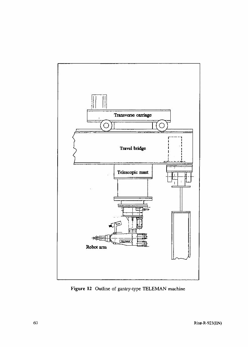
Transverse carriage
O) ToT
Travel bridge
Telescopic mast
Robot arm
[.A..
1
Figure 12 Outline of gantry-type TELEMAN machine
60 Ris0-R-923(EN)

!fbto
1 Identification
ROBOT ARM
Electrical motor
Bearings
Gear
Brakes
Limit switches
Position indicators
Electrical cables &plugs
Signal wires & connec-tors
Compressed air hoses* plugs
Compressed air supply
Compressed air cylin-ders
Functions Failure Modes
Failure to start,Failure to operate
Bearing laikjre
Electrical failure
Failure of start relay
Failure of bearings
Failure of gear
Failure of brakes
Failure of limit switches
Failure of positionindicators
Fracture,short circuit
Fracture,short circuit
Fracture
Failure of solenoidvalves
Failure of relative mo-vement
Failure Causes
Conven-tional
Various
Various
Various
Various
Mechanical
Mechanical
Electrical
Electrical,mechanical
Electrical,mechanical
Electrical,mechanical
Mechanical
Mechanical
Mechanical
Radiationdamage to
Lubricant
Insulation
Component
Lubricant
Lubricant
Sensors
Sensors
Insulation
Cables, insu-lation
Hoses
Component
Component
Serviceinterval
(h)
2000
FailureEffects
onSystem
Robot Arm MotionSystem Failure
Failure of brake
End stop failure
Robot Motion SystemFailure
Failure of signalling toand from manipulator
Failure of compressedair to the manipulator
No compressed air tocylinders
Failure of cylinder move-ment
FailureEffects
onRobot
FailureDetectionPossibility
No arm motion
Brake inoperable
No Arm Motion
No signals frommanipulator
No compressedair to manipulator
No cylinder move-ment
OperatorActions
Repair
Figure 13 Example of a FMEA form
O\
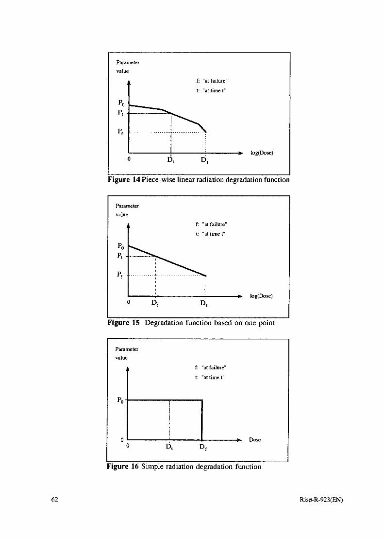
Parameter
value
Po
p , •
Pf
(> E
f: "at failure"
t: "at time t"
Figure 14 Piece-wise linear radiation degradation function
Parameter
value
i
Pop , •
Pf
(
1
—55*
) E
f: "at failure"
t: "at time t"
Figure 15 Degradation function based on one point
Parameter
value
j
0()
1
Dt
f: "at failure"
t: "at time t"
Df
Dose
Figure 16 Simple radiation degradation function
62 Ris0-R-923(EN)

Appendix A: Participating staff from each partner
SCK.CEN, Mol:• Marc Decreton, tel. +32 14 33 26 55, e-mail: [email protected]
• Simon Coenen, tel. +32 14 33 26 57, e-mail: [email protected]
• Dirk Van Beckhoven, tel. +32 14 33 26 14, e-mail: [email protected] for all three: Research Unit Waste and Dismantling, SCK»CEN NuclearResearch Centre, 200 Boeretang, B-2400 Mol, Belgium. Fax +32 14 31 19 93.
Siemens AG:• Claudia-Christina Seifert, tel. +49 69 807 4849, fax +49 69 807 2480,
E-mail: seifertc@offbl 1.kwu.siemens.de
Address: Siemens AG, KWU, NLL 3, Postfach 10 10 63, D-63010 Offenbach,Germany
• Dr. Hans-Joachim Roegler, NL-S (technical project leader)Tel.: +49-9131-18-6420, Fax: +49-9131-18-6685
Address: Siemens AG, KWU, P.O. Box 3230, D-91050 Erlangen, Germany• Anneli Benemann (retired)• Jan Podgorski (retired)
• Hartwig Rohrs (retired) (technical project leader)
AEA Technology• Richard E. Sharp, tel. +44 1235 46 3407, e-mail: [email protected]
• Lee Pater, tel. +44 1235 46 4003, e-mail: [email protected]
Address for both: AEA Technology, F4 Culham, Abingdon, Oxfordshire, OX14 3DB,
United Kingdom. Fax +44 1235 46 3041.
Ris0 National Laboratory:• Kurt Lauridsen, tel. +45 4677 5124, e-mail: [email protected]• Palle Christensen, tel. +45 4677 5122, e-mail: [email protected]
• Hans E. Kongs0, tel. +45 4677 5123, e-mail: [email protected]
• Kurt E. Petersen, tel. +45 4677 5121, e-mail: [email protected]
Address of the above: Ris0 National Laboratory, SYS-110, P.O. Box 49, DK-4000Roskilde, Denmark. Fax +45 4675 7101
• Per E. Becher, tel. +45 4677 4928, fax +45 4675 3533
Address: Ris0 National Laboratory, NUK-201, P.O. Box 49, DK-4000 Roskilde,Denmark.
• Igor O. Kozin (guest scientist 1994-96), tel. +7 08439 78467, fax +7 09525 52225,(private telephone: +7 08439 45175)
Address: Obninsk Institute of Nuclear Power Engineering, Studgorodok, INPE,Obninsk, Russia 249020.
Ris0-R-923(EN) 63

IMEC• Prof. Claeys, tel: +32 16 28 12 11, fax +32 16 22 94 00
Address: IMEC, Kapeldreef, 75, B-3030 Leuven (Belgium)
• Jean Pierre Colinge (now professor in Microelectronics at UCL University in Louvain-la-Neuve)
Radiation Experiments and Monitors (REM)• Andrew Holmes-Siedle, tel. +44 1865 880050, fax +44 1865 880030, e-mail:
[email protected]: 64A Acre End Street, Eynsham, Oxford OX8 1PD, England.
Remote Handling Consultant (R.H.C.)• Roger Home, tel./fax: +33 5041 1765.
Address: 26 La Vigne au Chat, 01220 Sauverny, Divonne, France.
64 Ris0-R-923(EN)

Appendix B: List of data sets in the database
AMPLIFIERDeviceAMP01AHA2520HA2620HA2700LM108LM108ALM108AFLM108AH
Records12213156
BIPOLAR TRANSISTORDevice2N37042N39042N3906BC108BC109BC109CBC212
Records6278221
DeviceLM118LM124LM124AJOP07OP07AJOP08-883AJOP16OP16AJ
DeviceBC549CBC559BC559CBCY70BCY71BCY72BFY50
Records82221111
Records4648442
COMPARATOR / FOLLOWER / REGULATORDeviceCMP05BJLM105LM105HLM111HLM117LM117HLM117KLM119LM137HLM139LM139A
CONVERTERSDeviceAD565ATAD574
Records12141221211
Records12
FET N CHANNELDevice2N4856A2N51962N6756
Records211
DeviceLM139AFLM139AJLM139AYLM139JLM193AH/833CLT1021BMH-10MC1723GOP220AZOP221AZOP400AYOP421
DeviceDAC08DAC08Q
Device2N67642N67662N6782
Records23142111111
Records11
Records454
DeviceOP27OP27AJOP37AJOP97PM157AJSFC2118MSMP11AY
DeviceZTX108ZTX109CZTX214CZTX650ZTX750
DeviceOP470AYPM-111REF10AJREF43SFC2105SG1524SG1524BJSG1524JTL074MJBTL084UA723
DeviceTP5211
Device2N67842N67862N6796
Records1111111
Records31242
Records11211121112
Records2
Records224
Ris0-R-923(EN) 65

FET N CHANNEL (continued)Device Records2N6798 52N6800 12N6802 1
FET P CHANNELDevice2N68042N6806
FIBRE OPTICDevice
Records42
CABLERecords
AS100/140A 1AS200/280A 1FBP200220240 1FHP200220240 1
FORCE SENSORSDevice Records5960R 1CEA-06-125UW350 4
HIGH POWER NPNDevice2N26582N28802N34212N3439
HIGH POWERDevice2N36372N50052N5153
INCLINATIONDevice3920UA-1-SW2
LOW POWERDevice2N22192N22222N2222A2N23692N2369A2N2484
Records1624
PNPRecords
344
SENSORRecords
111
NPNRecords
113236
DeviceFHX04FLC091FSX02
Device2N68452N6849
DeviceFIP100110125FVP100110125G15G099DF16HCRM0200T05
DeviceFSR-ULTEM
Device2N37492N50042N51542N5154HR
Device2N5153HR2N54152N5416
LEDDevice1N6094
Device2N28572N30132N30192N32532N35012N5666
Records111
Records25
Records7717
Records1
Records1441
Records121
Records2
Records122282
DeviceMGF1425NE202NE673
Device2N6851
DeviceST-R 100C(V)TCLM0100H12
DeviceSK-06-125DQ-350
Device2N56642N5664B2N5672LM110
DeviceBUX78
DeviceBUX77MMCM2222MMCM2369MMCM2484YFXFJ
Records121
Records2
Records1
14
Records4
Records7141
Records3
Records11111
66 Ris0-R-923(EN)

LOW POWER PNPDevice2N29052N2905A
Records14
MICROPROCESSORDevice RecordsHS-80C85RH 1MA31750 1MAS281 1
MOSFETDevice2N7330RH504AESAPMOS1
MULTIPLE NPNDevice2N2219A2N29202N2920A
MULTIPLE PNPDeviceMD2905AMQ3467
Records184
Records532
Records12
Device2N29072N2907A
MICROWAVEDeviceNE57807NE64508
DeviceIRF510IRF511IRF720
DeviceMD2219AFMHQ3467MQ2219A
DeviceS501TS502T
MULTIPLIER/REGISTER/COUNTERDeviceHCC40105BD
OPERATIONALDeviceLF155H/883C
OSCILLATORDeviceX5016
Records1
AMPLIFIERRecords
1
Records1
PHOTOCOUPLERDevice Records3C91C 36N134 1
DeviceLM107J/883C
Records34
Records12
Records333
Records122
Records11
Records1
OTHER FUNCTIONSDevice RecordsCD40116
DeviceCNY18OP224/OP604
1
Records31
Device2N3251A2N3467
DeviceIRF9522IRF9523VN67AFD
DeviceMQ2905AMQ3725ULS2004H
Records13
Records333
Records112
MULTIVIBRATORDevice4D4047B
DeviceLM124AJ/883C
Records1
Records: 4
Ris0-R-923(EN) 67

POSITION SENSORDeviceKD2310-15UMA40S20
POWER DIODEDevice1N4001GP1N40061N5401
SIGNAL DIODEDevice1N41481N916AA119
Records11
Records
to t
o
toRecords
522
DeviceU15 SPL
Device1N54061N5624
DeviceBAT85BAW62OA202
Records1
Records12
Records222
POTENTIOMETERDevice RecordsCP-2UT 19HRP08/1E/340/8K 19
PROXIMITY SENSORDeviceNJ5-18-GMOAS-ml8rg-lk
SWITCHINGDevice1N4148
Records11
Records1
TIMER / TRIGGER / SWITCHDevice RecordsDG182 2 LM555H
TRANSCEIVER / RECEIVER / DRIVER
SW201Q
DeviceSNJ55107SNJ55182
VOLTAGEDevice1N8271N4733A1N4739A1N5336B1N5338B1N5347BBZT03C10BZT03C36
VOLTAGEDeviceLM113
Records11
REFERENCE /Records
12222223
REGULATORRecords
1
DeviceSNJ55183UA55110A
ZENER DIODEDeviceBZV85C10BZV85C36BZV85C5V1BZW03C10BZX55C10BZX55C36BZX55C5V1BZX70C10
Records11
Records22222212
DeviceBZX70C36BZX79C10BZX79C36BZX79C5V1BZX85C10BZX85C36BZX85C5V1
Records2323222
68 Ris0-R-923(EN)

Bibliographic Data Sheet Ris0-R-923(EN)
Title and authors
Reliability and radiation tolerance of robots for nuclear applications
Kurt Lauridsen, Marc Decr6ton, Claudia-Christina Seifert, Richard E. Sharp
ISBN
87-550-2219-7
Dept. or group
Systems Analysis Department
Group's own reg. numbers)
Pages Tables
68
Appendices
A: Participating staff from each partnerB: List of data sets in the database
Date
October 1996
ISSN
0106-2840
Project/contract No.
MIR-02585EC contract FI2T-CT90-0011
Illustrations
16
References
236
Abstract
The reliability of a robot for nuclear applications will be affected by environmentalfactors such as dust, water, vibrations, heat, and, in particular, ionising radiation.The present report describes the work carried out in a project addressing thereliability and radiation tolerance of such robots.
A widely representative range of components and materials has been radiation testedand the test results have been collated in a database along with data provided by theparticipants from earlier work and data acquired from other sources. A radiationeffects guide has been written for the use by designers of electronic equipment forrobots. A generic reliability model has been set up together with generic failurestrategies, forming the basis for specific reliability modelling carried out in otherprojects. Modelling tools have been examined and developed for the prediction ofthe performance of electronic circuits subjected to radiation. Reports have beenproduced dealing with the prediction and detection of upcoming failures inelectronic systems.
Operational experience from the use of robots in radiation work in various contextshas been compiled in a report, and another report has been written on cost/benefitconsiderations about the use of robots. Also the possible impact of robots on thesafety of the surrounding plant has been considered and reported.
Descriptors INIS/EDB
COORDINATED RESEARCH PROGRAMMES; DATA BASE MANAGEMENT;ELECTRONIC CIRCUITS; FAILURE MODE ANALYSIS; MATHEMATICALMODELS; NUCLEAR INDUSTRY; PHYSICAL RADIATION EFFETS;RELIABILITY; REMOTE HANDLING EQUIPMENT; ROBOTS
Available on request from Information Service Department, Ris0 National Laboratory(Afdelingen for Informationsservice, Forskningscenter Riso), P.O. Box 49,DK-4000 RoskUde, DenmarkTelephone (+45) 46 77 46 77, ext. 4004/4005Telex 43 116 • Telefax (+45) 46 75 56 27

ObjectiveRis0's objective is to provide society and industry withnew opportunities for development in three main areas:
• Energy technology and energy planning• Environmental aspects of energy, industrial and agricultural production• Materials and measuring techniques for industry
In addition, Ris0 advises the authorities on nuclear issues.
Research profileRis0's research is strategic, which means that it islong-term and directed toward areas which technologicalsolutions are called for, whether in Denmark or globally.The reasearch takes place within 11 programme areas:
• Wind energy• Energy materials and energy technologies for the future• Energy planning• Environmental impact of atmospheric processes• Processes and cycling of matter in ecosystems• Industrial safety• Environmental aspects of agricultural production• Nuclear safety and radiation protection• Structural materials• Materials with special physical and chemical properties• Optical measurement techniques and information processing
Ris0-R-923(EN)ISBN 87-550-2219-7ISSN 0106-2840
Available on request from:Information Service DepartmentRis0 National LaboratoryEO. Box 49, DK-4000 Roskilde, DenmarkPhone +45 46 77 46 77, ext. 4004/4005Telex 43116, Fax +45 46 75 56 27http://www.risoe.dke-mail: [email protected]
Transfer of KnowledgeRis0's research results are transferred to industry andauthorities through:
• Co-operation on research• Co-operation in R&D consortia• R&D clubs and exchange of researchers• Centre for Advanced Technology• Patenting and licencing activities
And to the world of science through:
• Publication activities• Network co-operation• PhD education and post docs
Key FiguresRis0 has a staff of more than 900, including more than 300researchers and 100 PhD students and post docs. Ris0's1996 budget totals DKK 471 m, of which 45 % come fromresearch programmes and commercial contracts, while theremainder is covered by government appropriations.
![Teach Industrial Robots Peg-Hole-Insertion by Human ...wjchen84.github.io/publications/C2016_AIM.pdf · robots such as Baxter [11] and PR2 [12], with the as-sembly tolerance H5h10](https://img.pdfslide.net/doc/110x75/5fd89ccc18ad255b9c791b66/teach-industrial-robots-peg-hole-insertion-by-human-robots-such-as-baxter-11.jpg)


![Computation of Sequential AVF - People | MIT CSAILpeople.csail.mit.edu/emer/papers/2015.12.micro.seqavf.pdf · B.8 [Performance and Reliability]: B.8.1 Reliability, Testing, and Fault-Tolerance](https://img.pdfslide.net/doc/110x75/5f4ca22e09b5fa18f7092d5b/computation-of-sequential-avf-people-mit-b8-performance-and-reliability.jpg)

![Recovering Device Drivershomes.cs.washington.edu/~levy/shadowdrivers.pdfall to existing device drivers. Categories and Subject Descriptors: D.4.5 [Operating Systems]: Reliability—Fault-tolerance](https://img.pdfslide.net/doc/110x75/5f3efee720fffb50a938bd45/recovering-device-levyshadowdriverspdf-all-to-existing-device-drivers-categories.jpg)