Embed Size (px)
Citation preview

DATAKOM DKG-705 Dual Genset Parallel Application
Electronics Ltd.
[email protected] http://www.datakom.com.tr
Tel: +90-216-466 84 60 Fax: +90-216 364 65 65
DKG-705 DUAL GENSET PARALLEL APPLICATION
FEATURES Automatic mains failure, Engine control, Generator protection, Built in alarms and warnings, Programmable analogue inputs: 4 Programmable digital inputs: 8 Programmable relay outputs: 7 I/O expansion capability, Periodic maintenance request indicator, True RMS AC measurements, Statistical counters, Event logging, Field adjustable parameters,
Governor and AVR control outputs, Dual genset parallel with load sharing, Dual Genset Paralleling with the mains, Dual Genset No break transfer, Dual Genset Soft transfer, Single Genset Load capability, Automatic Start/Stop depending on load, Quick and delayed start depending on load, G-59 protections, Remote monitoring (MS-Windows based), RS-232 serial port, Software downloadable from serial port,
VERSION: 01.10 DATE: 09-05-2005

DATAKOM DKG-705 Dual Genset Parallel Application
705-DUAL_USER.doc - 2 -
TABLE OF CONTENTS Section
1. INTRODUCTION 2. APPLICATION BASICS 3. APPLICATION VARIANTS
3.1. Dual Genset with Soft Transfer to and from the Mains 3.2. Dual Genset with No Break Transfer to and from the Mains 3.3. Dual Genset with Interrupted Transfer
3.4 Dual Genset with fixed Master and Interrupted Transfer 3.5 Dual Genset with Remote Start 4. DISPLAYS AND MODE SWITCHING 5. PROGRAMMING IN DUAL GENSET MODE 6. INSTALLATION 6.1. Serial Communication Cable 6.2. Checking the Mains Phase Rotation Direction 6.3. Checking the Genset Phase Rotation Direction 6.4. Adjusting the Governor Control Output 6.5. Adjusting the AVR Control Output 6.6. Synchronizing two Gensets 6.7. Load Sharing 6.8. Synchronizing with Mains 6.9. Automatic Master / Slave Switching 7. MAINTENANCE 8. DECLARATION OF CONFORMITY 9. TECHNICAL SPECIFICATIONS 10. CONNECTION DIAGRAMS

DATAKOM DKG-705 Dual Genset Parallel Application
705-DUAL_USER.doc - 3 -
1. INTRODUCTION This manual describes the Dual Genset Synchronization specific features of the DKG-705 unit and should be considered as a supplement to the DKG-705 User Manual. Topics already emphasized the DKG-705 User Manual will not be repeated in this document. 2. APPLICATION BASICS The DKG-705 offers a simple and cost effective solution for paralleling two gensets with load sharing. The unit allows the synchronization scheme defined in the below picture. This is the basic application with one mains input and two gensets running in parallel.
The Dual Genset application is made with standard DKG-705 units and standard software, no extra hardware or software is needed. The same DKG-705 unit is able to be used in both single genset and dual genset applications.
The two gensets may be of a different rating; this will not effect the load sharing. They will share the load with equal percentage of their rated active power. For example if a 200KW genset is running in parallel with a 1000KW genset under 600KW total load, the first genset will supply 100KW and the second genset will supply 500KW. Reactive load sharing will be made the same way. One of the gensets will be selected as the MASTER one, it will determine the voltage and the frequency of the genset system. The other one will be called the SLAVE genset and will do the task of load sharing. The master/slave switching may be done in several ways: -one of the gensets may be constantly master, -manual master/slave switching, -automatic master/slave switching. Different master/slave switching applications will be explained in detail later in this document with related schematic diagrams. The load transfer between mains and gensets may be interrupted, uninterrupted or soft transfer with ramp control. Practically the unit is able to adapt to all kind of AVRs and governor controllers without additional hardware. The AVR control output is an isolated resistor with adjustable range, the governor control output is a 0-10V DC output. When a mains failure occurs, both gensets will run, synchronize and supply the load. Depending on user defined power levels and time delays, the master unit may decide to stop the slave genset.
The load switching is also controlled by the DKG-705 units.

DATAKOM DKG-705 Dual Genset Parallel Application
705-DUAL_USER.doc - 4 -
3. APPLICATION VARIANTS
3.1 Dual Genset with Soft Transfer to and from the Mains
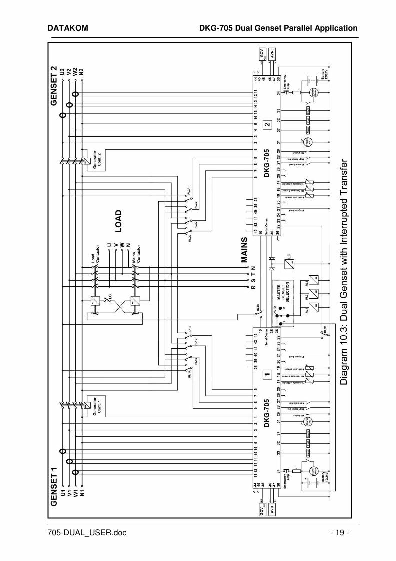
This configuration given in the schematic diagram 10.1 represents the most complex application of the DKG-705 in Dual Genset mode. The load will be gradually transferred between mains and gensets with KW and KVAr ramp control. The features of this application are: -Both gensets able to be Master or Slave, -Both automatic and manual master/slave switching allowed, -Soft transfer to/from the mains allowed, 3.2 Dual Genset with No Break Transfer to and from the Mains This configuration given in the schematic diagram 10.2 is similar to the one given in the schematic diagram 10.1 with the exception that there will be no need for the mains current transformers. To transfer the load, the gensets will synchronize to the mains, then close both contactors and then open the unnecessary contactor. The features of this application are: -Both gensets able to be Master or Slave, -Both automatic and manual master/slave switching allowed, -No Break transfer to/from the mains allowed, 3.3 Dual Genset with Interrupted Transfer This configuration given in the schematic diagram 10.3 is similar to the one given in the schematic diagram 10.1 with the exception that there will be no need for the mains current transformers. To transfer the load, the gensets will open both contactors and then close the necessary contactor. The features of this application are: -Both gensets able to be Master or Slave, -Both automatic and manual master/slave switching allowed,
If this transfer method is used, it is advised to make an electrical interlock between LOAD and MAINS contactors to prevent a phase to phase short circuit.
3.4 Dual Genset with fixed Master and Interrupted Transfer This configuration given in the schematic diagram 10.4 is the simplest application of a dual genset synchronized system. The master/slave selection cannot be changed. This configuration offers the advantage of using the master genset without AVR and GOV controls. Thus a small uncontrolled genset may be paralleled with a large genset. The small genset will supply enough power for non-working hours. Thus the large size genset will only run in work hours, which brings economy. An electrical interlock between Mains Contactor and Load Contactor is also advised. To transfer the load, the gensets will open both contactors and then close the necessary contactor.

DATAKOM DKG-705 Dual Genset Parallel Application
705-DUAL_USER.doc - 5 -
3.5 Dual Genset with Remote Start This configuration given in the schematic diagram 10.5 excludes the load transfer to mains since there are no mains available. Either fixed or selectable master application is possible. The related schematic diagram features both automatic and manual master/slave switching. 4. DISPLAYS AND MODE SWITCHING In a dual genset system, the front panel mimic diagram indicates the dual genset system status on both units:
Genset led ( ): turns on if the master genset generator contactor is closed (when Single Genset Load Enable parameter P_A32=1) or both generator contactors are closed (when Single Genset Load Enable parameter P_A32=0)
Mains led ( ): turns on when the mains voltages are applied to the master genset.
Genset contactor ( ): turns on when the load contactor is closed.
Mains contactor ( ): turns on when the mains contactor is closed. In a dual genset system, the operating mode selection is always made on the master unit, the slave unit always switches to AUTO mode but its operation is controlled by the master unit.

DATAKOM DKG-705 Dual Genset Parallel Application
705-DUAL_USER.doc - 6 -
5. PROGRAMMING IN DUAL GENSET MODE Below parameters are needed to be programmed carefully in Dual Genset Mode: Group Parameter Definition Unit Min Max Description
6 601 Current Transformer Primary
A 50 5000 This is the rated value of current transformers for both mains and genset. All transformers must have the same rating. The secondary of the transformer will be 5 Amps.
6 629 Emergency Backup - 0 1 If this parameter is set to 1, in the TEST mode, the load will be transferred to the genset if the mains fail.
6 633 Mains Current Transformers
- 0 1 0: Mains current transformers are not connected. All mains current, power and cosΦ values are zeros, peak lopping and soft transfer to genset are not allowed 1: Mains current transformers are connected and used. All mains current, power and cosΦ measurements are valid, peak lopping and soft transfer to genset are allowed.
Group Parameter Definition Value Description
7 770 Digital input 7 function 22 Force Master mode 7 771 Digital input 7 alarm
level 3 No alarm given from this input
7 772 Digital input 7 delay 0 Delay= 1 second. This is the detection speed of the input.
7 773 Digital input 7 sampling type
0 Always active. The signal is continuously checked.
7 774 Digital input 7 latching 0 Non latching. The alarm turns off when the alarm signal is removed.
7 775 Digital input 7 contact type
0 Normally open, closed on signal.
7 776 Digital input 7 switch polarity
0 Battery (-) switching. The signal source pulls to battery negative (ground).
Group Parameter Value Definition Terminal
8 801 12 Master request relay for dual 36 8 807 10 Load Contactor relay for dual 35

DATAKOM DKG-705 Dual Genset Parallel Application
705-DUAL_USER.doc - 7 -
Group Param. Definition Unit Value Description
10 A00 No Break Transfer - 0 0: Single genset no break transfer disabled. 10 A01 Soft Transfer Enable - 0 0: Single genset soft transfer disabled. 10 A02 GOV Control Enable - 1 0: Governor control disabled.
1: Governor control enabled. 10 A03 GOV Reverse Polarity - 1 0: Governor control normal polarity (speed
increases with voltage increase). 1: Governor control reverse polarity (speed decreases with voltage increase).
10 A04 AVR Control Enable - 1 0: AVR control disabled. 1. AVR control enabled.
10 A05 AVR Reverse Polarity - 0 0: AVR control normal polarity (voltage increases with resistor decrease). 1: AVR control reverse polarity (voltage decreases with resistor decrease).
10 A06 Ignore Phase Order - 0 0: Phase order check enabled. This option is used in 3 phase gensets. 1: Phase order check disabled. This option is used in single phase gensets.
10 A07 Synchronization Fail Timeout
Sec. 60 If the phase and voltage synchronization is not successful before the expiration of this timer, then a Synchronization Fail Warning or alarm is given.
10 A08 Soft Transfer Timer Sec. 20 This is the time duration of the Soft Transfer. At the end of this timer one of the contactors will release to terminate the parallel operation.
10 A09 Contactor Timeout Sec. 0.5 This is the maximum time duration in which both contactors are active in case of No Break Transfer.
10 A10 Max Frequency Difference
Hz 0.5 This is the maximum difference between mains and genset frequencies to accept the synchronization. Note that the DKG-705 adjusts the GOV output to bring the genset to the same frequency with the mains.
10 A11 Max Voltage Difference
V 5 This is the maximum difference between the mains phase-R and the genset phase-U voltages to accept the synchronization. Note that the DKG-705 adjusts the AVR output to bring the genset to the same voltage with the mains.
10 A12 Max Phase Difference Deg. 5 This is the maximum phase difference between the mains phase-R and the genset phase-U to accept the synchronization. Note that the DKG-705 adjusts the GOV output to bring the genset to the same phase with the mains.
10 A13 Governor Start - 128 This is the rest value of the governor control output. Always set this value to 128, which is the mid-course. However, if needed, engine frequency adjustment may be made through this parameter.
10 A14 AVR Start - 160 This is the rest value of the AVR control output. Always set this value to 160. However, if needed, genset voltage adjustment may be made through this parameter.
DATAKOM DKG-705 Dual Genset Parallel Application
705-DUAL_USER.doc - 8 -
Group Param. Definition Unit Value Description
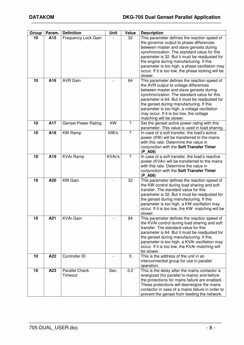
10 A15 Frequency Lock Gain - 32 This parameter defines the reaction speed of the governor output to phase differences between master and slave gensets during synchronization. The standard value for this parameter is 32. But it must be readjusted for the engine during manufacturing. If this parameter is too high, a phase oscillation may occur. If it is too low, the phase locking will be slower.
10 A16 AVR Gain - 64 This parameter defines the reaction speed of the AVR output to voltage differences between master and slave gensets during synchronization. The standard value for this parameter is 64. But it must be readjusted for the genset during manufacturing. If this parameter is too high, a voltage oscillation may occur. If it is too low, the voltage matching will be slower.
10 A17 Genset Power Rating KW ? Set the genset active power rating with this parameter. This value is used in load sharing.
10 A18 KW Ramp KW/s ? In case of a soft transfer, the load’s active power (KW) will be transferred to the mains with this rate. Determine the value in conjunction with the Soft Transfer Timer (P_A08)
10 A19 KVAr Ramp KVAr/s ? In case of a soft transfer, the load’s reactive power (KVAr) will be transferred to the mains with this rate. Determine the value in conjunction with the Soft Transfer Timer (P_A08)
10 A20 KW Gain - 32 This parameter defines the reaction speed of the KW control during load sharing and soft transfer. The standard value for this parameter is 32. But it must be readjusted for the genset during manufacturing. If this parameter is too high, a KW oscillation may occur. If it is too low, the KW matching will be slower.
10 A21 KVAr Gain - 64 This parameter defines the reaction speed of the KVAr control during load sharing and soft transfer. The standard value for this parameter is 64. But it must be readjusted for the genset during manufacturing. If this parameter is too high, a KVAr oscillation may occur. If it is too low, the KVAr matching will be slower.
10 A22 Controller ID - 0 This is the address of the unit in an interconnected group for use in parallel operation.
10 A23 Parallel Check Timeout
Sec. 0.2 This is the delay after the mains contactor is energized (for parallel to mains) and before the protections for mains failure are enabled. These protections will deenergize the mains contactor in case of a mains failure in order to prevent the genset from feeding the network.

DATAKOM DKG-705 Dual Genset Parallel Application
705-DUAL_USER.doc - 9 -
Group Param. Definition Unit Value Description
10 A24 Reverse Power Limit KW ? This parameter defines the sensitivity of the reverse power protection while operating in parallel with the mains. When the parallel protections are enabled, if the genset supplies a power over this limit to the mains, the mains contactor will be deenergized and a warning will be generated. It is advised to set this parameter to 25% of the genset power rating.
10 A25 ROCOF df/dt Limit Hz/Sec
5.0 This parameter defines the sensitivity of the ROCOF (rate of change of frequency) protection while operating in parallel with mains. When the parallel protections are enabled, if the mains frequency change exceeds this limit for 4 consecutive periods, the mains contactor will be deenergized and a warning will be generated. It is advised to set this parameter to 5 Hz/Sec.
10 A26 Vector Shift Limit Degr. 10 This parameter defines the sensitivity of the vector shift protection while operating in parallel with mains. When the parallel protections are enabled, if the phase of the mains measured on last 2 cycles jumps over this limit on the phase measured on last 4th and 5th period, the mains contactor will be deenergized and a warning will be generated. It is advised to set this parameter to 10 degrees.
10 A27 Peak Lopping Enable - 0 Peak lopping disabled. In AUTO mode the genset will start only if a mains failure occurs.
10 A31 Dual Genset Operation Enable
- 1 Dual genset operation.
10 A32 Single Genset Load Enable (dual genset mode)
- 0 0: Single genset loading disabled. On mains failure both gensets will run and synchronize between them, after this the load will be transferred to gensets. 1: Single genset loading enabled. On mains failure, at first the master genset will take the load and then the slave genset will synchronize and share the load. Also when one of the gensets fails, the other will be authorized to feed the load.
10 A33 Dual Genset No Break Transfer to Mains Enable
- ? 0: No break transfer disabled. 1: No break transfer enabled.
10 A34 Dual Genset Soft Transfer to Mains Enable
- ? 0: Soft transfer disabled. 1: Soft transfer enabled.

DATAKOM DKG-705 Dual Genset Parallel Application
705-DUAL_USER.doc - 10 -
Group Param. Definition Unit Value Description
10 A35 Dual Genset Delayed Start Power
% ? If the total active load is above this level for the period defined in P_A38, the slave genset will start, synchronize and share the load. This parameter is defined as a percentage of the Genset Power Rating defined in parameter P_A17.
10 A36 Dual Genset Quick Start Power
% ? If the total active load is above this level, the slave genset will start, synchronize and share the load without delay. This parameter is defined as a percentage of the Genset Power Rating defined in parameter P_A17.
10 A37 Dual Genset Delayed Stop Power
% ? If the total active load is below this level for the period defined in P_A38, the slave genset will stop. This parameter is defined as a percentage of the Genset Power Rating defined in parameter P_A17.
10 A38 Dual Genset Start/Stop Delay
Sec 5 This is the time delay used for starting and stopping of the slave genset. Related starting and stopping power levels are defined in parameters P_A35 and P_A37.
10 A39 Master Genset Frequency Lock Gain in Dual Genset Mode
- 4 This parameter defines the reaction speed of the governor output to phase differences between the dual genset system and mains phases during synchronization. The standard value for this parameter is 4. But it must be readjusted for the dual genset system during manufacturing. If this parameter is too high, a phase oscillation may occur. If it is too low, the phase locking will be slower.
10 A40 Master Genset AVR Gain in Dual Genset Mode
- 8 This parameter defines the reaction speed of the AVR output to voltage differences between the dual genset system and mains phases during synchronization. The standard value for this parameter is 8. But it must be readjusted for the dual genset system during manufacturing. If this parameter is too high, a voltage oscillation may occur. If it is too low, the voltage matching will be slower.

DATAKOM DKG-705 Dual Genset Parallel Application
705-DUAL_USER.doc - 11 -
6. INSTALLATION The installation is a more complex and delicate work in a dual genset system comparing a single genset application. Before running the gensets make sure that the panel cabling is correctly applied and program parameters are set in coherence with the genset specifications. Before running tests, disable the dual genset mode via programming menu on both units. (P_A31=0) 6.1. Serial Communication Cable Use a standard cross type serial cable to connect the two gensets. The cable configuration is:
DKG-705 DKG-705 D_SUB 9 pin male……………………………….. D_SUB 9 pins male Pin_2…………………… connected to…………… pin_3 Pin_3…………………… connected to…………… pin_2 Pin_5…………………… connected to…………… pin_5 (using the shield)
If the cable connection is not made correctly, this will result in a COMMUNICATION FAIL alarm or warning. If Single Genset Load Enable parameter is set (P_A32=1) a warning is issued and the dual system will operate as a single genset system. If Single Genset Load Enable parameter is not set (P_A32=0) an alarm is issued and the dual system will not operate. 6.2. Checking the Mains Phase Rotation Direction 1) Apply the mains voltages to the dual genset system. 2) Set the Master Selection switch on position 1, in order to apply the mains voltages to the genset 1.
3) Check that the green MAINS led on the mimic diagram turns on. 4) Check that no MAINS PHASE SEQUENCE warning appears. If the warning appears change the order of any two phases outside the panel, before current transformers. Make sure that the connections of the panel are not modified with this operation; otherwise severe problems will arise in the continuing tests. Misplaced phases or current transformers are delicate to rearrange. 5) Set the Master Selection switch on position 2, in order to apply the mains voltages to the genset 2. 6) Repeat steps 3 and 4 for the genset 2. 7) Cut the mains phase voltages. 6.3. Checking the Genset Phase Rotation Direction Before running tests, disable the dual genset mode via programming menu on both units. (P_A31=0)
Switch the genset-1 to LOAD TEST mode. Wait until the genset runs and the yellow GENSET led of the mimic diagram turns on, then stop the engine. If a GENSET PHASE SEQUENCE Alarm occurs, change the order of any two phases outside the panel, before current transformers. Make sure that the connections of the panel are not modified with this operation; otherwise severe problems will arise in the continuing tests. Misplaced phases or current transformers are delicate to rearrange. Repeat the same test for genset 2.

DATAKOM DKG-705 Dual Genset Parallel Application
705-DUAL_USER.doc - 12 -
6.4. Adjusting the Governor Control Output Before running tests, disable the dual genset mode via programming menu on both units. (P_A31=0) The GOV output of the unit is a 0-10V DC output with 180 ohms internal impedance. Connect the GOV output (terminal 48) to the AUXILIARY input or J input of the electronic governor controller. Make sure that the Governor Start parameter (P_A13) is set to 128 in programming menu. Switch the unit on TEST mode. The genset will run. Adjust the desired genset frequency using the electronic governor controller’s SPEED potentiometer. Get in the programming menu and start increasing the Governor Start parameter (P_A13). The engine speed should decrease. If the engine speed increases, then set the Gov Reverse Polarity parameter (P_A03) to 0. Increase the engine speed using the Governor Start parameter (P_A13) in small steps until end value (0 or 255). The engine speed should not rise excessively. If this happens, insert a resistor (or potentiometer) serially to the GOV output. The value of the resistor should be determined in order to obtain approximately +/- 5Hz frequency variation when the Governor Start parameter (P_A13) sweeps between 0 and 255. Repeat the same operations for the genset 2. 6.5. Adjusting the AVR Control Output Before running tests, disable the dual genset mode via programming menu on both units. (P_A31=0) The AVR outputs of the unit are similar to an isolated resistor with variable value. Connect the AVR outputs (terminals 46-47) to the voltage adjusting potentiometer inputs of the AVR. The connection cable should be of coaxial type. Connect the cable shield to ground. Make sure that the AVR Start parameter (P_A14) is set to 160 in programming menu. Adjust approximately the unit’s rear panel AVR adjusting potentiometer. For 1K-ohms AVRs turn the knob clockwise until stop. For 100 K-ohm AVRs, turn the knob to anticlockwise approximately to 80% course. Switch the unit on TEST mode. The genset will run. Adjust the desired genset voltage using the AVR controller’s VOLT potentiometer. Get in the programming menu and start decreasing the AVR Start parameter (P_A14). The genset voltage should decrease. If the genset voltage increases, then set the AVR Reverse Polarity parameter (P_A05) to 1. Increase the genset voltage using the AVR Start parameter (P_A14) in small steps until end (0 or 255). The genset voltage should not rise excessively. If this happens, turn the unit’s rear panel AVR adjusting potentiometer in clockwise direction. The position of the potentiometer should be determined in order to obtain approximately +/- 25 volt variation in the genset voltage when the AVR Start parameter (P_A14) sweeps between 0 and 255. Repeat the same operations for the genset 2.

DATAKOM DKG-705 Dual Genset Parallel Application
705-DUAL_USER.doc - 13 -
6.6. Synchronizing two Gensets Before running tests, enable the dual genset mode via programming menu on both units. (P_A31=1) Check that the communication cable between two gensets is installed. Check that no COMMUNICATION ERROR alarm or warning appears. It is advised to use an oscilloscope to visualize the synchronization process. The first channel will display the genset bar phase-U voltage and the second channel will display the slave genset phase-U voltage. The triggering will use the channel-1. Disconnect the slave unit’s generator contactor output in order to prevent an eventual phase-to-phase short circuit. Switch the master unit to TEST mode. Both gensets will run and the master genset will operate its generator contactor. Then the master will issue a command to the slave unit for synchronization. The slave unit will switch to the synchronization display screen. Watch the phase matching process on the oscilloscope screen. Adjust the Frequency Lock Gain parameter (P_A15) for the fastest phase locking. If this parameter is too high, a phase oscillation may occur. If it is too low, the phase locking will be slower. Set an adequate value for a fast matching without oscillation. If no oscilloscope is available, watch the synchronization screen for frequency matching. The slave genset should match the master frequency in 2 to 5 seconds. Adjust the value of P_A15 in order to obtain this delay. Another way of adjusting the synchronization is to measure the delay. If the phase matching does not occur in 10 seconds, reduce the value of the parameter P_A15 to half of its value and restart the test until an acceptable synchronization delay is obtained. The voltage matching between master and slave gensets is adjusted with the AVR Gain parameter (P_A16). Generally this parameter is not critical and often does not require a special adjustment. It defines the reaction speed of the AVR output to voltage differences between master and slave gensets during synchronization. If this parameter is too high, a voltage oscillation may occur. If it is too low, the voltage matching will be slower. 6.7. Load Sharing Before running tests: -enable the dual genset mode via programming menu on both units. (P_A31=1) -set the dual genset delayed stop power (P_A37) to 0%. Check that the communication cable between two gensets is installed. Check that no COMMUNICATION ERROR alarm or warning appears. Switch the master unit to LOAD TEST mode. Both gensets will run, the slave will synchronize on the master and the load share process will begin. Follow the load share screen displayed on slave unit LCD display. If there is possibility to load the systems, suddenly load the system at 50% of the nominal load and follow the KW fluctuations on the LCD. The system should get in the equilibrium in approximately 5 seconds. If the response is stable but slow, then increase the KW gain parameter (P_A20). If the response is fast but with fluctuations, then decrease the KW gain parameter. Unload the system and suddenly reload it with 50% of the nominal load and follow the KVAr fluctuations on the LCD. The system should get in the equilibrium in approximately 5 seconds. If the response is stable but slow, then increase the KVAr gain parameter (P_A21). If the response is fast but with fluctuations, then decrease the KVAr gain parameter. If the two gensets are identical the same values of P_A20 and P_A21 may be used commonly. If they are different, toggle the master/slave selection and make the same adjustments for the other genset.

DATAKOM DKG-705 Dual Genset Parallel Application
705-DUAL_USER.doc - 14 -
6.8. Synchronizing with Mains Before running tests: -enable the dual genset mode via programming menu on both units. (P_A31=1) -set the dual genset delayed stop power (P_A37) to 0%. -enable Dual Genset No Break Transfer to Mains (P_A33=1). Check that the communication cable between two gensets is installed. Check that no COMMUNICATION ERROR alarm or warning appears. It is advised to use an oscilloscope to visualize the synchronization process. The first channel will display the mains phase R voltage and the second channel will display the genset bar phase-U voltage. The triggering will use the channel-1. Disconnect the load contactor coil to prevent an eventual phase-to-phase short circuit. Switch the master unit to LOAD TEST mode. Both gensets will run and supply the genset bar. Then the master will start synchronization to mains. It will switch to the synchronization display screen. Watch the phase matching process on the oscilloscope screen. Normally phase matching to mains is a delicate process as speed changes of the master genset influences also the load share. Adjust the Master Genset Frequency Lock Gain in Dual Genset parameter (P_A39) for the smoothest phase locking. The phase locking with mains is a slower process than phase locking between two gensets. If this parameter is too high, a phase oscillation may occur. If it is too low, the phase locking will be slower. Set an adequate value for a smooth matching without oscillation. If no oscilloscope is available, watch the synchronization screen for frequency matching. The dual genset system should match the mains frequency in approximately 10 seconds. Adjust the value of P_A39 in order to obtain this delay. Another way of adjusting the synchronization is to measure the delay. If the phase matching does not occur in 20 seconds, reduce the value of the parameter P_A39 to half of its value and restart the test until an acceptable synchronization delay is obtained. The voltage matching between mains and dual genset system is adjusted with the Master Genset AVR Gain in Dual Genset Mode parameter (P_A40). Generally this parameter is not critical and often does not require a special adjustment. It defines the reaction speed of the AVR output to voltage differences between mains and dual genset system during synchronization. If this parameter is too high, a voltage oscillation may occur. If it is too low, the voltage matching will be slower.

DATAKOM DKG-705 Dual Genset Parallel Application
705-DUAL_USER.doc - 15 -
6.9. Automatic Master / Slave Switching The dual genset system may be installed with automatic master/slave switching feature. The main advantages of this system are: -automatic master/slave switching in case of failure in master genset -equal aging of both gensets -simultaneous periodic maintenance request on both gensets. The master/slave selection is made on each unit using an external master request input signal. This signal may be: -hard wired if there is no need for master/slave switching, -manually switched if a manual master/slave switching is required, -operated by the Master relay output of one unit, if automatic master/slave switching is required. The MASTER RELAY output is energized if the Engine Hours to Service of the master genset is equal or greater than the Engine Hours to Service of the slave genset. The MASTER RELAY output is deenergized if the Engine Hours to Service of the master genset is lower than the Engine Hours to Service of the slave genset. The slave unit’s MASTER RELAY output is always the opposite of the master unit’s output, thus the switching will be correctly done by any of the two units. 7. MAINTENANCE
DO NOT OPEN THE UNIT
There are NO serviceable parts inside the unit.
Wipe the unit, if necessary with a soft damp cloth. Do not use chemical agents
8. DECLARATION OF CONFORMITY
The unit conforms to the EU directives
-73/23/EEC and 93/68/EEC (low voltage) -89/336/EEC, 92/31/EEC and 93/68/EEC (electro-magnetic compatibility)
Norms of reference: EN 61010 (safety requirements) EN 50081-2 (EMC requirements) EN 50082-2 (EMC requirements) The CE mark indicates that this product complies with the European requirements for safety, health environmental and customer protection. 9. TECHNICAL SPECIFICATIONS
The technical specifications are identical to the standard DKG-705 unit. 10. CONNECTION DIAGRAMS Sample connection diagrams for each case studied in section_3 are given below.

DATAKOM DKG-705 Dual Genset Parallel Application
705-DUAL_USER.doc - 16 -

DATAKOM DKG-705 Dual Genset Parallel Application
705-DUAL_USER.doc - 17 -

DATAKOM DKG-705 Dual Genset Parallel Application
705-DUAL_USER.doc - 18 -
DATAKOM DKG-705 Dual Genset Parallel Application
705-DUAL_USER.doc - 19 -

DATAKOM DKG-705 Dual Genset Parallel Application
705-DUAL_USER.doc - 20 -

DATAKOM DKG-705 Dual Genset Parallel Application
705-DUAL_USER.doc - 21 -

DATAKOM DKG-705 Dual Genset Parallel Application
705-DUAL_USER.doc - 22 -
DATAKOM Electronics Limited Tel : +90-216-466 84 60 Fax : +90-216-364 65 65 e-mail : [email protected] http: www.datakom.com.tr