Embed Size (px)
Citation preview

IM 701610-17E4th Edition
Digital OscilloscopeCommunication Interface
DL1620/DL1640/DL1640L
iIM 701610-17E
IntroductionThank you for purchasing YOKOGAWA’s DL1620/DL1640/DL1640L Digital
Oscilloscope.
This Communication Interface User’s Manual describes the functions and commands of
the serial (RS-232), GP-IB (optional) , USB (optional), and Ethernet (optional) interfaces,
mainly with the DL1640. To ensure proper use of the GP-IB/serial (RS-232)/USB
interfaces, please read this manual thoroughly.
Keep the manual in a safe place for quick reference whenever a question arises.
Five manuals are provided with the DL1620/DL1640/DL1640L including this
Communication Interface User’s Manual.
Manual Name Manual No. Description
DL1620/DL1640/DL1640L IM 701610-01E Describes all functions except for theUser’s Manual communications functions and operation
procedures of the instrument.
DL1620/DL1640/DL1640L IM 701610-02E Explains basic operations only.Operation Guide
DL1620/DL1640/DL1640L IM 701610-17E Describes the communications functionsCommunication Interface of the GP-IB/serial (RS-232)/USB/User’s Manual Ethernet interfaces.
DL1640/DL1640L IM 701610-51E Describes the CAN bus signal analysis functionCAN Bus Signal Analysis and SPI bus signal analysis function (option).Function
DL1640/DL1640L IM 701610-61E Describes the I2C-bus signal analysis functionI2C-Bus Signal Analysis and SPI bus signal analysis function (option).Function
Notes• The contents of this manual are subject to change without prior notice as a result of
improvements in instrument’s performance and functions.
• Every effort has been made in the preparation of this manual to ensure the accuracy
of its contents. However, should you have any questions or find any errors, please
contact your nearest YOKOGAWA dealer.
• Copying or reproduction of all or any part of the contents of this manual without
YOKOGAWA’s permission is strictly prohibited.
• A guarantee card is attached to the instrument. The card will not be reissued, so
please read it carefully and keep it in a safe place.
USB Interface and Ethernet Interface• The following items must be installed on the PC to access the communications
functions using the USB interface.
1. A dedicated library for the USB interface.
2. A USB device driver for the PC-to-DL1620/DL1640/DL1640L connection.
• The following item must be installed on the PC to access the communications
functions using the Ethernet interface.
1. A dedicated library for the network interface.
For information on obtaining the library or the driver, please contact your sales
representative.
4th Edition : July 2005 (YK)
All Rights Reserved, Copyright © 2002 Yokogawa Electric Corporation
ii IM 701610-17E
Trademarks• Microsoft, MS-DOS, Visual C++, Windows, Windows NT, Windows Me, and
Windows XP are either registered trademarks or trademarks of Microsoft
Corporation in the United States and/or other countries.
• Adobe, Acrobat, and PostScript are either trademarks or registered trademarks of
Adobe Systems incorporated.
• Zip is a registered trademark or trademark of Iomega corporation in the United States
and/or other countries.
• For purposes of this manual, the TM and ® symbols do not accompany their
respective trademark names or registered trademark names.
• Other product names are trademarks or registered trademarks of their respective
holders.
• The TCP/IP software and TCP/IP-related documentation accompanying this
instrument was developed/created from the BSD Networking Software, Release 1
licensed from the Regents of the University of California.
Revisions1st Edition: August 2002
2nd Edition: February 2003
3rd Edition: December 2003
4th Edition: July 2005
iiiIM 701610-17E
How to Use this Manual
Structure of this ManualThis User’s Manual consists of eight chapters, an Appendix and an Index as described
below.
Chapter 1 Overview of the Serial (RS-232) Interface
Describes the functions and specifications of the serial interface (RS-232).
Chapter 2 Overview of the GP-IB Interface (Option)
Describes the functions and specifications of the GP-IB interface.
Chapter 3 Overview of the USB Interface (Option)
Describes the functions and specifications of the USB interface.
Chapter 4 Overview of the Ethernet Interface (Option)
Describes the functions and specifications of the Ethernet interface.
Chapter 5 Before Programming
Describes formats used when sending a command.
Chapter 6 Commands
Describes each command.
Chapter 7 Status Report
Describes the status byte, various registers and queues.
Chapter 8 Sample Programs
Sample programs, written in Visual BASIC, for MS-DOS/V machines
equipped with the following GP-IB board: AT-GPIB/TNT IEEE-488.2, from
National Instruments.
Appendix
Contains references including the ASCII character code table.
Index
Provides an index ordered alphabetically.
iv IM 701610-17E
Conventions Used in this ManualUnits
k ............. Denotes 1000. Example: 100 kS/s (sample rate)
K ............ Denotes 1024. Example: 720 KB (storage capacity of a floppy disk)
Displayed Characters
• Bold characters used in the procedural explanations indicate characters that are
displayed on the panel keys for the respective procedure or the characters on the
screen.
• SHIFT+key means you will press SHIFT to turn ON the indicator that is located to the
left of SHIFT followed by the operation key. The menu written above or below the
pressed key appears on the screen.
Symbols
The following symbols are used in to this manual.
Note Provides information that is important for proper operation of the
instrument.
Terms Used for Descriptions of Operations
The following terms are used in chapters 1 to 4 to distinguish certain features in
descriptions.
Operating Procedure Carry out steps in the order shown. The operating
procedures are given with the assumption that you
are not familiar with the operation. Thus, it may not
be necessary to carry out all the steps when
changing settings.
Explanation Describes settings and restrictions relating to the
operation.
Symbols Used for Notes and Keys
Type Symbol Description
Unitk 1000 e.g.: 100 kS/s (sample rate)K 1024 e.g.: 720 KB (floppy disk memory capacity)
Notes Note Provides information that is necessary for proper operation of the instrument.
Key "Probe" Refers to a soft key displayed on the screen.
Symbols Used in Syntax Descriptions
Symbols which are used in the syntax descriptions in Chapter 6 are shown below.
These symbols are referred to as BNF notation (Backus-Naur Form). For detailed
information, refer to page 5-5.
Symbol Description Example Example of Input
< > Defined value CHANnel <x> <x>=1 to 4 -> CHANNEL2
One of the options in is selected. COUPling AC|DC|GND -> COUPLING AC| Exclusive OR
[ ] Abbreviated TRIGger [:SIMPle]:SLOPe -> TRIGger:SLOPe
How to Use this Manual
vIM 701610-17E
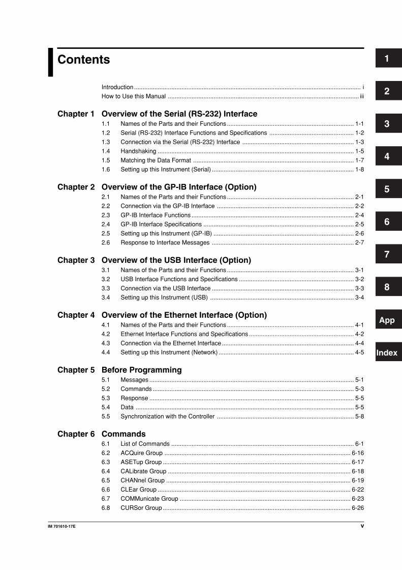
Contents
Introduction ...................................................................................................................................... i
How to Use this Manual ................................................................................................................. iii
Chapter 1 Overview of the Serial (RS-232) Interface 1.1 Names of the Parts and their Functions ........................................................................... 1-1
1.2 Serial (RS-232) Interface Functions and Specifications .................................................. 1-2
1.3 Connection via the Serial (RS-232) Interface .................................................................. 1-3
1.4 Handshaking .................................................................................................................... 1-5
1.5 Matching the Data Format ............................................................................................... 1-7
1.6 Setting up this Instrument (Serial) .................................................................................... 1-8
Chapter 2 Overview of the GP-IB Interface (Option)2.1 Names of the Parts and their Functions ........................................................................... 2-1
2.2 Connection via the GP-IB Interface ................................................................................. 2-2
2.3 GP-IB Interface Functions ................................................................................................ 2-4
2.4 GP-IB Interface Specifications ......................................................................................... 2-5
2.5 Setting up this Instrument (GP-IB) ................................................................................... 2-6
2.6 Response to Interface Messages .................................................................................... 2-7
Chapter 3 Overview of the USB Interface (Option)3.1 Names of the Parts and their Functions ........................................................................... 3-1
3.2 USB Interface Functions and Specifications .................................................................... 3-2
3.3 Connection via the USB Interface .................................................................................... 3-3
3.4 Setting up this Instrument (USB) ..................................................................................... 3-4
Chapter 4 Overview of the Ethernet Interface (Option)4.1 Names of the Parts and their Functions ........................................................................... 4-1
4.2 Ethernet Interface Functions and Specifications .............................................................. 4-2
4.3 Connection via the Ethernet Interface .............................................................................. 4-4
4.4 Setting up this Instrument (Network) ................................................................................ 4-5
Chapter 5 Before Programming5.1 Messages ......................................................................................................................... 5-1
5.2 Commands ....................................................................................................................... 5-3
5.3 Response ......................................................................................................................... 5-5
5.4 Data ................................................................................................................................. 5-5
5.5 Synchronization with the Controller ................................................................................. 5-8
Chapter 6 Commands6.1 List of Commands ............................................................................................................ 6-1
6.2 ACQuire Group .............................................................................................................. 6-16
6.3 ASETup Group ............................................................................................................... 6-17
6.4 CALibrate Group ............................................................................................................ 6-18
6.5 CHANnel Group ............................................................................................................. 6-19
6.6 CLEar Group .................................................................................................................. 6-22
6.7 COMMunicate Group ..................................................................................................... 6-23
6.8 CURSor Group ............................................................................................................... 6-26
1
2
3
4
5
6
7
8
App
Index
vi IM 701610-17E
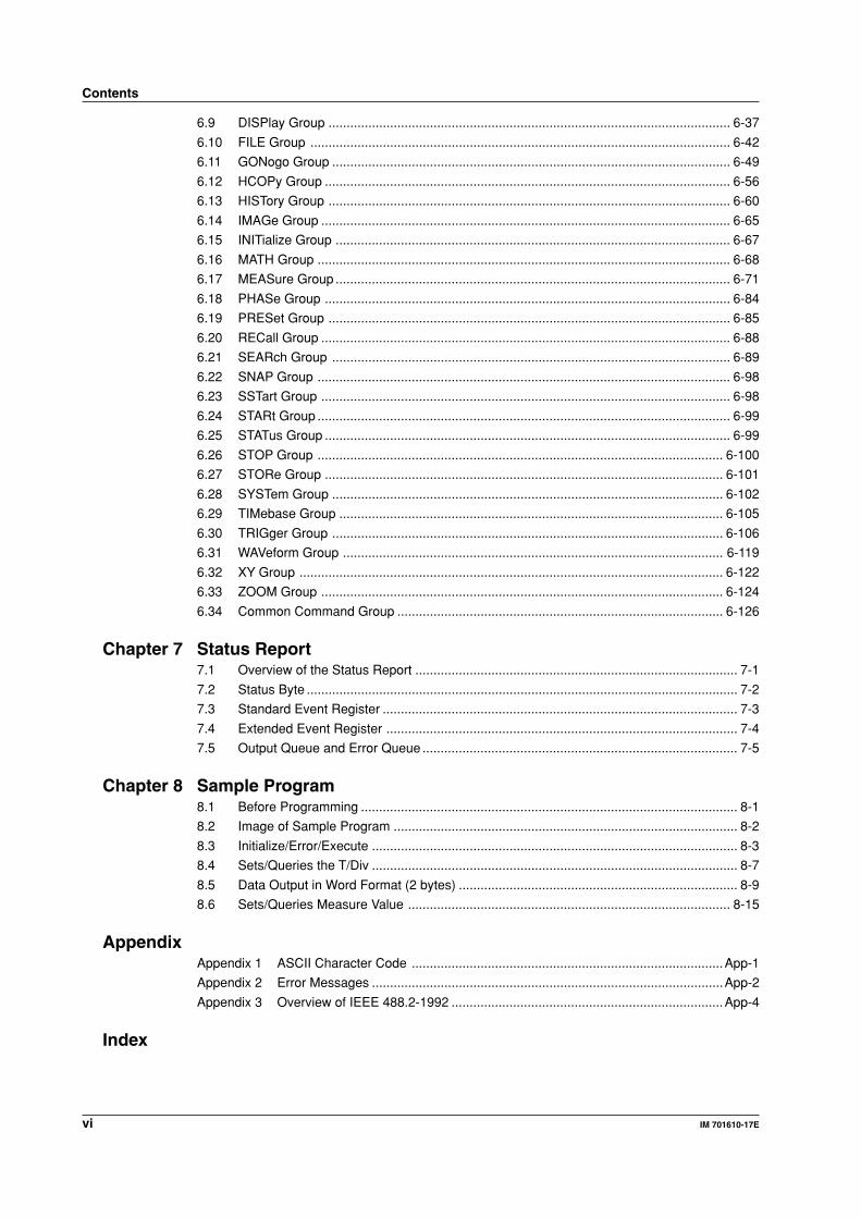
Contents
6.9 DISPlay Group ............................................................................................................... 6-37
6.10 FILE Group .................................................................................................................... 6-42
6.11 GONogo Group .............................................................................................................. 6-49
6.12 HCOPy Group ................................................................................................................ 6-56
6.13 HISTory Group ............................................................................................................... 6-60
6.14 IMAGe Group ................................................................................................................. 6-65
6.15 INITialize Group ............................................................................................................. 6-67
6.16 MATH Group .................................................................................................................. 6-68
6.17 MEASure Group ............................................................................................................. 6-71
6.18 PHASe Group ................................................................................................................ 6-84
6.19 PRESet Group ............................................................................................................... 6-85
6.20 RECall Group ................................................................................................................. 6-88
6.21 SEARch Group .............................................................................................................. 6-89
6.22 SNAP Group .................................................................................................................. 6-98
6.23 SSTart Group ................................................................................................................. 6-98
6.24 STARt Group .................................................................................................................. 6-99
6.25 STATus Group ................................................................................................................ 6-99
6.26 STOP Group ................................................................................................................ 6-100
6.27 STORe Group .............................................................................................................. 6-101
6.28 SYSTem Group ............................................................................................................ 6-102
6.29 TIMebase Group .......................................................................................................... 6-105
6.30 TRIGger Group ............................................................................................................ 6-106
6.31 WAVeform Group ......................................................................................................... 6-119
6.32 XY Group ..................................................................................................................... 6-122
6.33 ZOOM Group ............................................................................................................... 6-124
6.34 Common Command Group .......................................................................................... 6-126
Chapter 7 Status Report7.1 Overview of the Status Report ......................................................................................... 7-1
7.2 Status Byte ....................................................................................................................... 7-2
7.3 Standard Event Register .................................................................................................. 7-3
7.4 Extended Event Register ................................................................................................. 7-4
7.5 Output Queue and Error Queue ....................................................................................... 7-5
Chapter 8 Sample Program8.1 Before Programming ........................................................................................................ 8-1
8.2 Image of Sample Program ............................................................................................... 8-2
8.3 Initialize/Error/Execute ..................................................................................................... 8-3
8.4 Sets/Queries the T/Div ..................................................................................................... 8-7
8.5 Data Output in Word Format (2 bytes) ............................................................................. 8-9
8.6 Sets/Queries Measure Value ......................................................................................... 8-15
AppendixAppendix 1 ASCII Character Code ......................................................................................App-1
Appendix 2 Error Messages .................................................................................................App-2
Appendix 3 Overview of IEEE 488.2-1992 ...........................................................................App-4
Index
1-1IM 701610-17E
Overview
of th
e Serial (R
S-232) In
terface
1Chapter 1 Overview of the Serial (RS-232) Interface
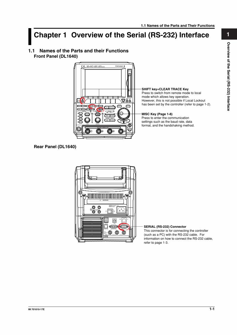
1.1 Names of the Parts and their FunctionsFront Panel (DL1640)
HELP
SELECTRESET
SIMPLE
ACTION DELAY
MODE POSITION
MATHMISCFILE
COPY
CLEARTRACE
HISTORY
MEASURE
PRESET
CURSOR
SETUP DISPLAY
X - Y
CH 1
CH 2
CH 3
CH 4
V DIV
POWER
TIME DIV
MENU
IMAGE SAVE
MENUPHASE
SHIFT
ZOOM
SEARCHHORIZONTALVERTICAL
GO/NOGO
COMP
ENHANCED
ACQ START/STOP
TRIGGERTRIG D
SNAPSHOT
MISC Key (Page 1-8)Press to enter the communication settings such as the baud rate, data format, and the handshaking method.
SHIFT key+CLEAR TRACE KeyPress to switch from remote mode to local mode which allows key operation. However, this is not possible if Local Lockout has been set by the controller (refer to page 1-2).
Rear Panel (DL1640)
SERIAL (RS-232) ConnectorThis connector is for connecting the controller (such as a PC) with the RS-232 cable. For information on how to connect the RS-232 cable, refer to page 1-3.
1.1 Names of the Parts and Their Functions
1-2 IM 701610-17E
1.2 Serial (RS-232) Interface Functions and Specifications
Reception FunctionIt is possible to make the same settings via the serial (RS-232) interface as can be made
using the front panel keys.
Measured/computed data, panel setup information and error codes can be received.
Transmission FunctionMeasured/computed data can be output.
Panel setup information and the status byte can be output.
Error codes which have occurred can be output.
Serial (RS-232) Interface SpecificationsElectrical Characteristics: Conforms to EIA 574 Standard (EIA-232 (RS-232) Standard
for 9-pin)
Connection: Point-to-point
Communications: Full-duplex
Synchronization: Start-stop system
Baud Rate: 1200, 2400, 4800, 9600, 19200, 38400, 57600
Start Bit: 1 bit (fixed)
Data Length: 7 or 8 bits
Parity: Even, odd or no parity
Stop Bit: 1 or 2 bits
Connector: DELC-J9PAF-13L6 (JAE or equivalent)
Hardware Handshaking: User can select whether CA or CB signals will always be
True, or will be used for control.
Software Handshaking: User can control both transmission and reception using X-on
and X-off signals. (X-on (ASCII 11H), X-off (ASCII 13H))
Receive Buffer Size: 256 bytes
Switching between Remote and Local ModeWhen Switched from Local to Remote Mode
Remote mode is activated when the ":COMMunicate:REMote ON" command is
received from a controller while local mode is active.
• REMOTE is displayed on the upper right of the screen.
• All front panel keys except SHIFT+CLEAR TRACE can no longer be operated any
more.
• Settings entered in local mode are retained.
When Switched from Remote to Local Mode
Pressing SHIFT+CLEAR TRACE in remote mode puts the instrument in local mode.
However, this is not possible of Local Lockout (when the ":COMMunicate:LOCKout
ON" command is received) has been set by the controller.
Local mode is activated when the ":COMMunicate:REMote OFF" command
regardless of Local Lockout.
• The REMOTE indicator on the upper right of the screen is turned off.
• All front panel keys are operative.
• Settings entered in remote mode are retained.
NoteThe serial interface cannot be used simultaneously with other communications interface (GP-
IB, USB, or network)
1.2 Serial (RS-232) Interface Functions and Specifications
1-3IM 701610-17E
Overview
of th
e Serial (R
S-232) In
terface
11.3 Connection via the Serial (RS-232) InterfaceWhen connecting this instrument to a computer, make sure that the handshaking
method, data transmission rate and data format selected for the instrument match those
selected for the computer.
For details, refer to the following pages. Also make sure that the correct interface cable
is used.
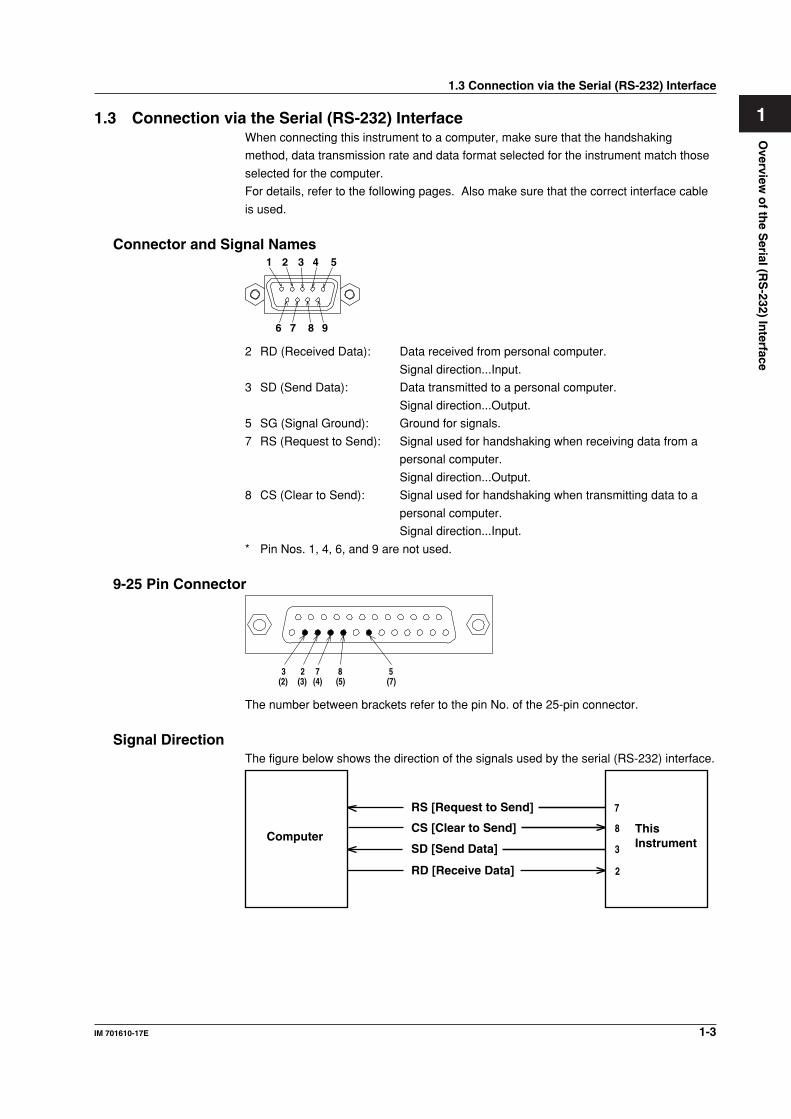
Connector and Signal Names21 3 4 5
6 7 8 9
2 RD (Received Data): Data received from personal computer.
Signal direction...Input.
3 SD (Send Data): Data transmitted to a personal computer.
Signal direction...Output.
5 SG (Signal Ground): Ground for signals.
7 RS (Request to Send): Signal used for handshaking when receiving data from a
personal computer.
Signal direction...Output.
8 CS (Clear to Send): Signal used for handshaking when transmitting data to a
personal computer.
Signal direction...Input.
* Pin Nos. 1, 4, 6, and 9 are not used.
9-25 Pin Connector
58723(2) (3) (4) (5) (7)
The number between brackets refer to the pin No. of the 25-pin connector.
Signal DirectionThe figure below shows the direction of the signals used by the serial (RS-232) interface.
ComputerThis Instrument
RS [Request to Send]
SD [Send Data]
RD [Receive Data] 2
3
8
7
CS [Clear to Send]
1.3 Connection via the Serial (RS-232) Interface
1-4 IM 701610-17E
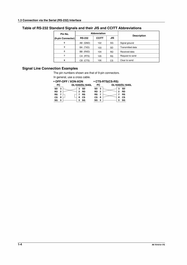
Table of RS-232 Standard Signals and their JIS and CCITT Abbreviations
Pin No.
(9-pin Connector)
Abbreviation
RS-232Description
CCITT JIS
5
3
2
8
7
AB (GND)
BA (TXD)
BB (RXD)
CB (CTS)
CA (RTS)
102 SG
103
104
106
105
SD
RD
CS
RS
Signal ground
Transmitted data
Request to send
Received data
Clear to send
Signal Line Connection ExamplesThe pin numbers shown are that of 9-pin connectors.
In general, use a cross cable.
SDRDRSCSSG
SDRDRS
SG
• OFF-OFF / XON-XONPC DL1640/DL1640L
SDRDRSCSSG
SDRDRS
SG
• CTS-RTS(CS-RS)PC DL1640/DL1640L
CS CS
2 3
8 7
5
2 3
8 7
5
2 3
8 7
5
2 3
8 7
5
1.3 Connection via the Serial (RS-232) Interface
1-5IM 701610-17E
Overview
of th
e Serial (R
S-232) In
terface
11.4 HandshakingTo use an serial (RS-232) interface for transferring data between this instrument and a
computer, it is necessary to use certain procedures by mutual agreement to ensure the
proper transfer of data. These procedures are called “handshaking.” Various
handshaking systems are available depending on the computer to be used; the same
handshaking system must be used for both the computer and this instrument.
This instrument allows you to choose any handshaking mode from the following three
modes.
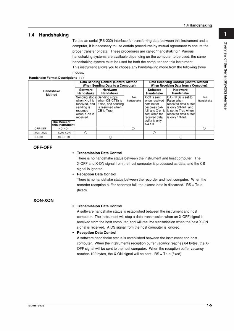
Data Sending Control (Control Method When Sending Data to a Computer)
Data Receiving Control (Control Method When Receiving Data from a Computer)
SoftwareHandshake
SoftwareHandshake
Handshake Format Descriptions→
NO-NO
XON-XON
CTS-RTS
HandshakeMethod
Sending stops when X-off is received, and sending is resumed when X-on is received.
Sending stops when CB(CTS) is False, and sending is resumed when CB is True.
Nohandshake
Nohandshake
X-off is sent when received data buffer becomes 3/4-full, and X-on is sent when the received data buffer is only 1/4-full.
CA (RTS) is set to False when received data buffer is only 3/4-full, and is set to True when received data buffer is only 1/4-full.
HardwareHandshake
HardwareHandshake
OFF-OFF
XON-XON
CS-RS
The Menu of this Instrument
OFF-OFF• Transmission Data Control
There is no handshake status between the instrument and host computer. The
X-OFF and X-ON signal from the host computer is processed as data, and the CS
signal is ignored.
• Reception Data Control
There is no handshake status between the recorder and host computer. When the
recorder reception buffer becomes full, the excess data is discarded. RS = True
(fixed).
XON-XON• Transmission Data Control
A software handshake status is established between the instrument and host
computer. The instrument will stop a data transmission when an X-OFF signal is
received from the host computer, and will resume transmission when the next X-ON
signal is received. A CS signal from the host computer is ignored.
• Reception Data Control
A software handshake status is established between the instrument and host
computer. When the intstruments reception buffer vacancy reaches 64 bytes, the X-
OFF signal will be sent to the host computer. When the reception buffer vacancy
reaches 192 bytes, the X-ON signal will be sent. RS = True (fixed).
1.4 Handshaking
1-6 IM 701610-17E
CS-RS• Transmission Data Control
A software handshake status is established between the instrument and host
computer. The instrument will stop a data transmission if a “CS = False” status is
established, and will resume the transmission when a “CS = True” status is
established. The X-OFF and X-ON signals from the host computer are processed as
data.
• Reception Data Control
A hardware handshake status is established between the instrument and host
computer. When the intstruments reception buffer vacancy reaches 64 bytes, an
“RS=False” status will be established. When the reception buffer vacancy reaches
192 bytes, an “RS=True” status will be established.
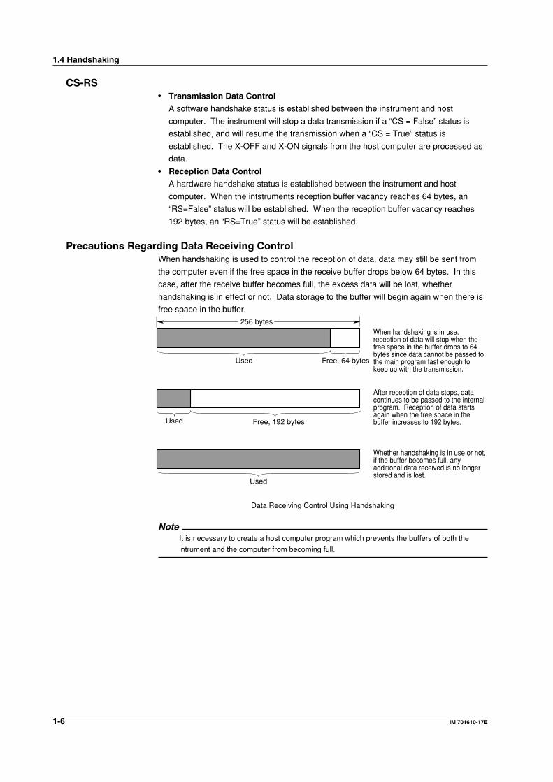
Precautions Regarding Data Receiving ControlWhen handshaking is used to control the reception of data, data may still be sent from
the computer even if the free space in the receive buffer drops below 64 bytes. In this
case, after the receive buffer becomes full, the excess data will be lost, whether
handshaking is in effect or not. Data storage to the buffer will begin again when there is
free space in the buffer.
256 bytes
Used Free, 64 bytes
When handshaking is in use, reception of data will stop when the free space in the buffer drops to 64 bytes since data cannot be passed to the main program fast enough to keep up with the transmission.
Used Free, 192 bytes
After reception of data stops, data continues to be passed to the internal program. Reception of data starts again when the free space in the buffer increases to 192 bytes.
Used
Whether handshaking is in use or not, if the buffer becomes full, any additional data received is no longer stored and is lost.
Data Receiving Control Using Handshaking
NoteIt is necessary to create a host computer program which prevents the buffers of both the
intrument and the computer from becoming full.
1.4 Handshaking
1-7IM 701610-17E
Overview
of th
e Serial (R
S-232) In
terface
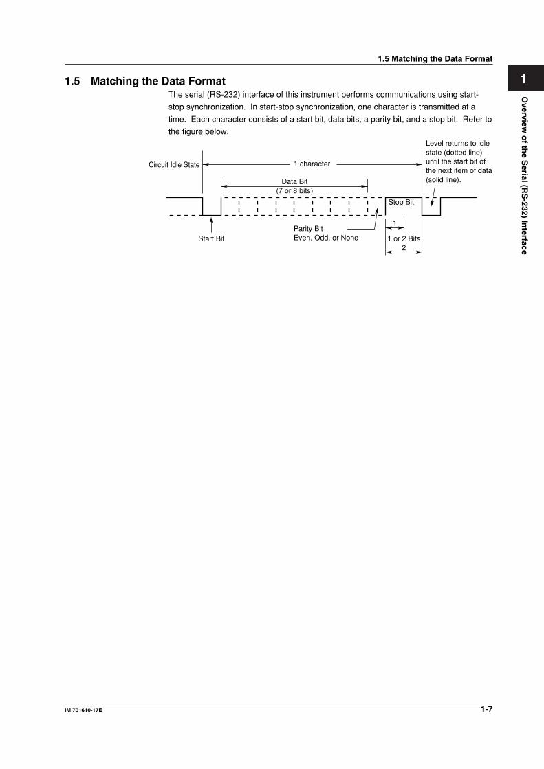
11.5 Matching the Data FormatThe serial (RS-232) interface of this instrument performs communications using start-
stop synchronization. In start-stop synchronization, one character is transmitted at a
time. Each character consists of a start bit, data bits, a parity bit, and a stop bit. Refer to
the figure below.
Data Bit(7 or 8 bits)
1 character
Stop Bit
1
1 or 2 Bits2
Parity BitEven, Odd, or NoneStart Bit
Circuit Idle State
Level returns to idlestate (dotted line)until the start bit ofthe next item of data(solid line).
1.5 Matching the Data Format
1-8 IM 701610-17E
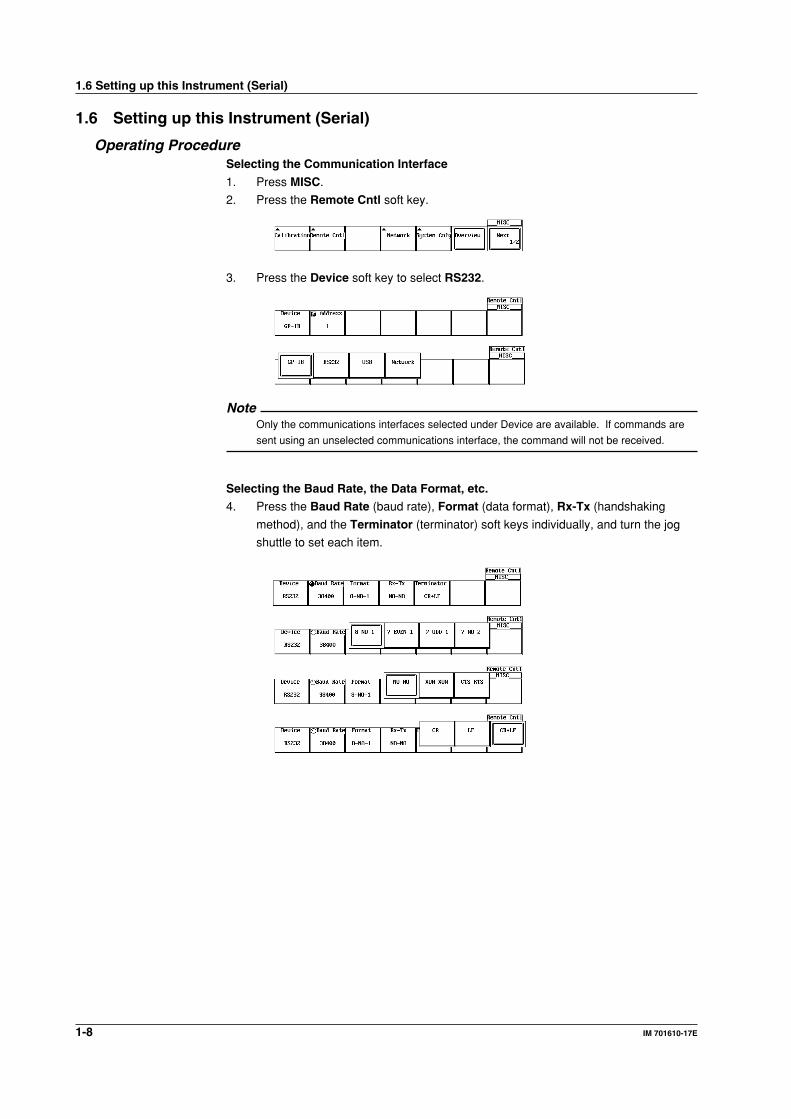
1.6 Setting up this Instrument (Serial)
Operating ProcedureSelecting the Communication Interface
1. Press MISC.
2. Press the Remote Cntl soft key.
3. Press the Device soft key to select RS232.
NoteOnly the communications interfaces selected under Device are available. If commands are
sent using an unselected communications interface, the command will not be received.
Selecting the Baud Rate, the Data Format, etc.
4. Press the Baud Rate (baud rate), Format (data format), Rx-Tx (handshaking
method), and the Terminator (terminator) soft keys individually, and turn the jog
shuttle to set each item.
1.6 Setting up this Instrument (Serial)
1-9IM 701610-17E
Overview
of th
e Serial (R
S-232) In
terface
1
1.6 Setting up this Instrument (Serial)
ExplanationWhen using the controller to set the items which can be set locally using the keys on the
instrument, or when outputting the setup information or the waveform data to the
controller, set the following items.
Baud Rate
Select from the following choices.
1200, 2400, 4800, 9600, 19200, 38400, 57600
Data Format
Select the combination of the data length and the stop bit from the following choices.
8-NO-1, 7-EVEN-1, 7-ODD-1, 7-NO-2
Handshaking Method
Select the transmit data control and the receive data control from the following choices.
NO-NO, XON-XON, CTS-RTS
Terminator
Select from the following choices. The terminator used when sending the data from this
instrument is selected on the menu. Use either “LF” or “CR+LF” for the terminator in
receiving the data.
CR, LF, CR+LF

2-1IM 701610-17E
Overview
of th
e GP
-IB In
terface (Op
tion
)
2
Chapter 2 Overview of the GP-IB Interface (Option)
2.1 Names of the Parts and their Functions
Front Panel (DL1640)
HELP
SELECTRESET
SIMPLE
ACTION DELAY
MODE POSITION
MATHMISCFILE
COPY
CLEARTRACE
HISTORY
MEASURE
PRESET
CURSOR
X - Y
CH 1
CH 2
CH 3
CH 4
V DIV
POWER
TIME DIV
MENU
IMAGE SAVE
MENUPHASE
SHIFT
ZOOM
SEARCHHORIZONTALVERTICAL
GO/NOGO
COMP
ENHANCED
ACQ START/STOP
TRIGGERTRIG D
SNAPSHOT
SETUP DISPLAY
SHIFT Key+CLEAR TRACE KeyPress to switch from remote mode to local mode which allows key operation. However, this is not possible if Local Lockout has been set by the controller (refer to page 2-7).
MISC Key (Page 2-6)Press to enter the communication settings such as the address and the timeout.
Rear Panel (DL1640)
GP-IB ConnectorThis connector is for connecting the controller (such as a PC) with the GP-IB cable. For information on how to connect the GP-IB cable, refer to the following page.
2.1 Names of the Parts and Their Functions
2-2 IM 701610-17E
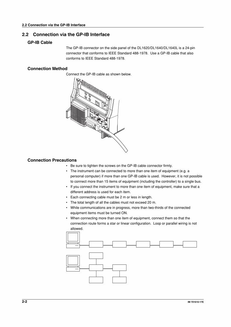
2.2 Connection via the GP-IB Interface
GP-IB CableThe GP-IB connector on the side panel of the DL1620/DL1640/DL1640L is a 24-pin
connector that conforms to IEEE Standard 488-1978. Use a GP-IB cable that also
conforms to IEEE Standard 488-1978.
Connection MethodConnect the GP-IB cable as shown below.
Connection Precautions• Be sure to tighten the screws on the GP-IB cable connector firmly.
• The instrument can be connected to more than one item of equipment (e.g. a
personal computer) if more than one GP-IB cable is used. However, it is not possible
to connect more than 15 items of equipment (including the controller) to a single bus.
• If you connect the instrument to more than one item of equipment, make sure that a
different address is used for each item.
• Each connecting cable must be 2 m or less in length.
• The total length of all the cables must not exceed 20 m.
• While communications are in progress, more than two-thirds of the connected
equipment items must be turned ON.
• When connecting more than one item of equipment, connect them so that the
connection route forms a star or linear configuration. Loop or parallel wiring is not
allowed.
2.2 Connection via the GP-IB Interface
2-3IM 701610-17E
Overview
of th
e GP
-IB In
terface (Op
tion
)
2
CAUTIONBe sure to switch off power to both your PC and the oscilloscope before
connecting or disconnecting cables. Failure to switch power off may causeinternal circuit failure or improper operation.
2.2 Connection via the GP-IB Interface
2-4 IM 701610-17E
2.3 GP-IB Interface Functions
GP-IB Interface FunctionsListener Function
• Allows you to make the settings which you can make using the panel keys on the
instrument, except for the power ON/OFF and GP-IB communications settings.
• Receives commands from a controller requesting output of setup and waveform data.
• Also receives status report commands.
Talker Function
Outputs setup and waveform data.
NoteThe listen-only, talk-only and controller functions are not available on this instrument.
Switching between Remote and Local ModeWhen Switched from Local to Remote Mode
Remote mode is activated when a REN (Remote Enable) message is received from a
controller while local mode is active.
• REMOTE is displayed on the upper right of the screen.
• All front panel keys except SHIFT+CLEAR TRACE can no longer be operated any
more.
• Settings entered in local mode are retained.
When Switched from Remote to Local Mode
Pressing SHIFT+CLEAR TRACE in remote mode puts the instrument in local mode.
However, this is not possible if Local Lockout has been set by the controller (page 2-7).
• The REMOTE indicator on the upper right of the screen is turned off.
• All front panel keys are operative.
• Settings entered in remote mode are retained.
NoteThe GP-IB interface cannot be used simultaneously with other communications interfaces
(serial (RS-232), USB, or network).
2.3 GP-IB Interface Functions
2-5IM 701610-17E
Overview
of th
e GP
-IB In
terface (Op
tion
)
2
2.4 GP-IB Interface Specifications
GP-IB Interface SpecificationsElectrical and Mechanical Specifications: Conforms to IEEE Standard 488-1978.
Interface Functions: Refer to the table below.
Protocol: Conforms to IEEE Standard 488.2-1992.
Code: ISO (ASCII) code
Mode: Addressable mode
Address Setting: Addresses 0 to 30 can be selected from the
GP-IB setting screen, displayed when you
press the MISC key.
Remote Mode Clear: Remote mode can be cleared by pressing
SHIFT key+CLEAR TRACE key. However,
this is not possible if Local Lockout has been
set by the controller.
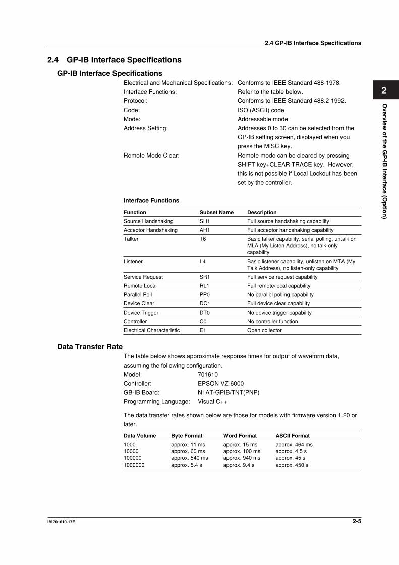
Interface Functions
Function Subset Name Description
Source Handshaking SH1 Full source handshaking capability
Acceptor Handshaking AH1 Full acceptor handshaking capability
Talker T6 Basic talker capability, serial polling, untalk onMLA (My Listen Address), no talk-onlycapability
Listener L4 Basic listener capability, unlisten on MTA (MyTalk Address), no listen-only capability
Service Request SR1 Full service request capability
Remote Local RL1 Full remote/local capability
Parallel Poll PP0 No parallel polling capability
Device Clear DC1 Full device clear capability
Device Trigger DT0 No device trigger capability
Controller C0 No controller function
Electrical Characteristic E1 Open collector
Data Transfer RateThe table below shows approximate response times for output of waveform data,
assuming the following configuration.
Model: 701610
Controller: EPSON VZ-6000
GB-IB Board: NI AT-GPIB/TNT(PNP)
Programming Language: Visual C++
The data transfer rates shown below are those for models with firmware version 1.20 or
later.
Data Volume Byte Format Word Format ASCII Format
1000 approx. 11 ms approx. 15 ms approx. 464 ms10000 approx. 60 ms approx. 100 ms approx. 4.5 s100000 approx. 540 ms approx. 940 ms approx. 45 s1000000 approx. 5.4 s approx. 9.4 s approx. 450 s
2.4 GP-IB Interface Specifications
2-6 IM 701610-17E
2.5 Setting up this Instrument (GP-IB)
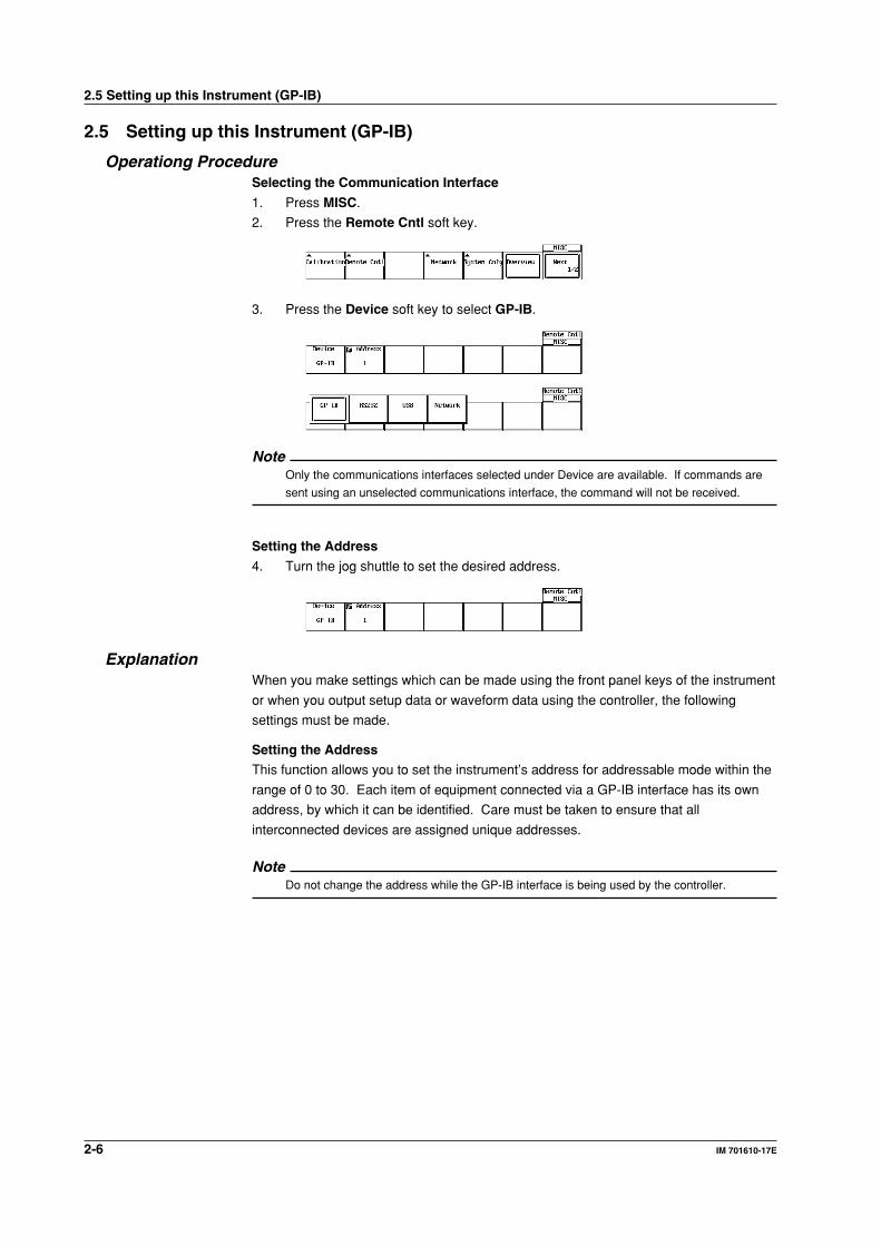
Operationg ProcedureSelecting the Communication Interface
1. Press MISC.
2. Press the Remote Cntl soft key.
3. Press the Device soft key to select GP-IB.
NoteOnly the communications interfaces selected under Device are available. If commands are
sent using an unselected communications interface, the command will not be received.
Setting the Address
4. Turn the jog shuttle to set the desired address.
ExplanationWhen you make settings which can be made using the front panel keys of the instrument
or when you output setup data or waveform data using the controller, the following
settings must be made.
Setting the Address
This function allows you to set the instrument’s address for addressable mode within the
range of 0 to 30. Each item of equipment connected via a GP-IB interface has its own
address, by which it can be identified. Care must be taken to ensure that all
interconnected devices are assigned unique addresses.
NoteDo not change the address while the GP-IB interface is being used by the controller.
2.5 Setting up this Instrument (GP-IB)

2-7IM 701610-17E
Overview
of th
e GP
-IB In
terface (Op
tion
)
2
2.6 Response to Interface Messages
Response to Interface MessageResponse to a Uni-line Message
IFC (InterFace Clear)
Clears the talker and listener. Stops output if data is being output.
REN (Remote ENable)
Switches between remote and local modes.
IDY (Identify) is not supported.
Response to a Multi-Line Message (Address Command)
GTL (Go To Local)
Switches to local mode.
SDC (Selected Device Clear)
Clears the program message (command) which is currently being output. Also clears the
output queue (page 7-5).
*OPC and *OPC? will be disabled if they are currently being executed.
*WAI and :COMMunicate:WAIT will be stopped immediately.
PPC (Parallel Poll Configure), GET (Group Execute Trigger) and TCT (Take Control) are
not supported.
Response to a Multi-Line Message (Universal Command)
LLO (Local LockOut)
Invalidates SHIFT+CLEAR on the front panel to disable switching to local mode.
DCL (Device CLear)
Same as SDC.
SPE (Serial Poll Enable)
Sets the talker function to serial poll mode for all equipment connected to the
communications bus. The controller performs polling on equipment sequentially.
SPD (Serial Poll Disable)
Clears serial poll mode as the talker function for all equipment connected to the
communications bus.
PPU (Parallel Poll Unconfigure) is not supported.
What is an Interface Message?An interface message is also called an interface command or bus command, and is
issued by the controller. Interface messages are classified as follows.
Uni-Line Messages
Messages are transferred through a single control line. The following three types of uni-
line message are available.
IFC (InterFace Clear)
REN (Remote ENable)
IDY (IDentifY)
2.6 Response to Interface Messages
2-8 IM 701610-17E
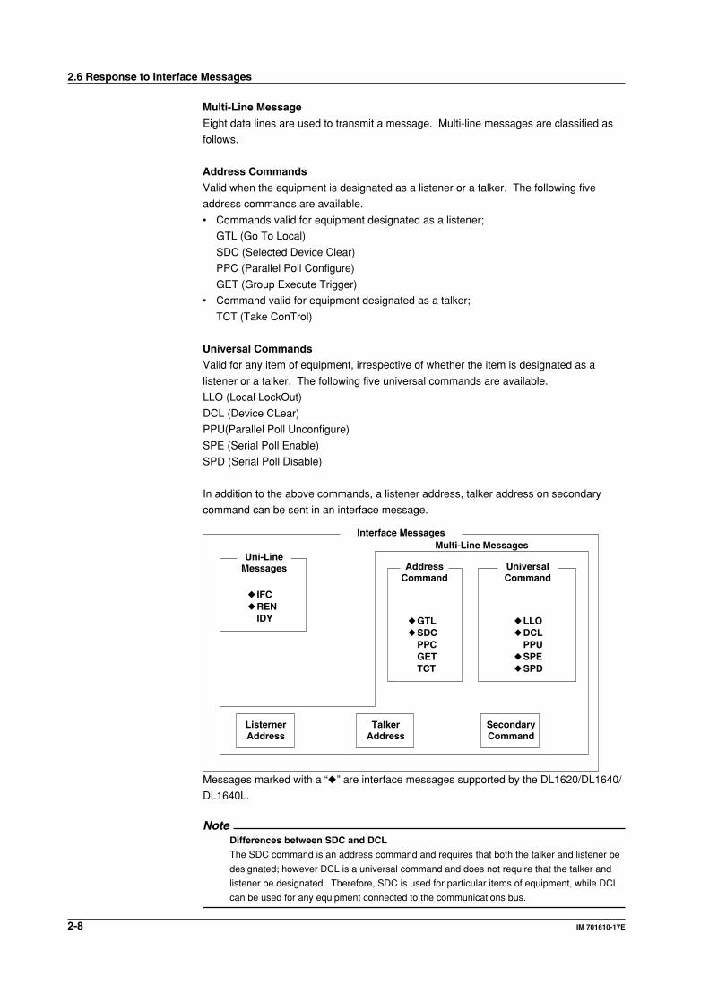
Multi-Line Message
Eight data lines are used to transmit a message. Multi-line messages are classified as
follows.
Address Commands
Valid when the equipment is designated as a listener or a talker. The following five
address commands are available.
• Commands valid for equipment designated as a listener;
GTL (Go To Local)
SDC (Selected Device Clear)
PPC (Parallel Poll Configure)
GET (Group Execute Trigger)
• Command valid for equipment designated as a talker;
TCT (Take ConTrol)
Universal Commands
Valid for any item of equipment, irrespective of whether the item is designated as a
listener or a talker. The following five universal commands are available.
LLO (Local LockOut)
DCL (Device CLear)
PPU(Parallel Poll Unconfigure)
SPE (Serial Poll Enable)
SPD (Serial Poll Disable)
In addition to the above commands, a listener address, talker address on secondary
command can be sent in an interface message.
Interface Messages
Uni-LineMessages Address
CommandUniversalCommand
IFC REN
IDY GTL SDC
PPCGETTCT
LLO DCL
PPU SPE SPD
ListernerAddress
TalkerAddress
SecondaryCommand
Multi-Line Messages
Messages marked with a “” are interface messages supported by the DL1620/DL1640/
DL1640L.
NoteDifferences between SDC and DCL
The SDC command is an address command and requires that both the talker and listener be
designated; however DCL is a universal command and does not require that the talker and
listener be designated. Therefore, SDC is used for particular items of equipment, while DCL
can be used for any equipment connected to the communications bus.
2.6 Response to Interface Messages
3-1IM 701610-17E
Overview
of th
e US
B In
terface (Op
tion
)
3
Chapter 3 Overview of the USB Interface (Option)
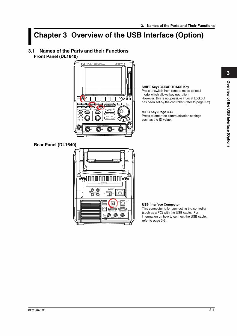
3.1 Names of the Parts and their FunctionsFront Panel (DL1640)
SHIFT Key+CLEAR TRACE KeyPress to switch from remote mode to local mode which allows key operation. However, this is not possible if Local Lockout has been set by the controller (refer to page 3-2).
MISC Key (Page 3-4)Press to enter the communication settings such as the ID value.
HELP
SELECTRESET
SIMPLE
ACTION DELAY
MODE POSITION
MATHMISCFILE
COPY
CLEARTRACE
HISTORY
MEASURE
PRESET
CURSOR
X - Y
CH 1
CH 2
CH 3
CH 4
V DIV
POWER
TIME DIV
MENU
IMAGE SAVE
MENUPHASE
SHIFT
ZOOM
SEARCHHORIZONTALVERTICAL
GO/NOGO
COMP
ENHANCED
ACQ START/STOP
TRIGGERTRIG D
SNAPSHOT
SETUP DISPLAY
Rear Panel (DL1640)
USB Interface ConnectorThis connector is for connecting the controller (such as a PC) with the USB cable. For information on how to connect the USB cable, refer to page 3-3.
3.1 Names of the Parts and Their Functions
3-2 IM 701610-17E
3.2 USB Interface Functions and Specifications
Reception FunctionYou can specify the same settings as those specified by front panel key operations.
Receives output requests for measured and computed data, setting parameters of the
panel, and error codes.
Transmission FunctionOutputs measured and computed data.
Outputs setting parameters of the panel and the status byte.
Outputs error codes that are generated.
USB Interface SpecificationsElectrical and Mechanical Specifications: Conforms to USB Rev.1.0
Connector: Type B connector (receptacle)
Number of Ports: 1
Power Supply: Self-powered
Supported Systems: PC system supported. Models with a standard
USB port that operates on Windows 98 SE,
Windows Me, Windows 2000, or Windows XP
(a separate device driver is required for
connection to the PC).
Switching between Remote and Local ModeWhen Switching from Local to Remote Mode
If the DL1620/DL1640/DL1640L receives a ":COMMunicate:REMote ON" command
from the PC when it is in the local mode, it switches to the remote mode.
• REMOTE is displayed at the lower left corner of the screen.
• All keys except SHIFT+CLEAR TRACE are disabled.
• The settings that existed in the local mode are maintained even when the DL1620/
DL1640/DL1640L switches to the remote mode.
When Switching from Remote to Local Mode
Pressing SHIFT+CLEAR TRACE when the instrument is in the remote mode causes the
instrument to switch to the local mode. However, this is void when the DL1620/DL1640/
DL1640L has received a ":COMMunicate:LOCKout ON" command from the PC (local
lockout condition). When the DL1620/DL1640/DL1640L receives a
":COMMunicate:REMote OFF" command from the PC, the DL1620/DL1640/DL1640L
switches to the local mode regardless of the local lock condition.
• REMOTE indication at the lower right corner disappears.
• Key operations are enabled.
• The settings that existed in the remote mode are maintained even when the
instrument switches to the local mode.
NoteThe USB interface cannot be used simultaneously with other communications interface (GP-
IB, serial (RS-232), or network).
3.2 USB Interface Functions and Specifications
3-3IM 701610-17E
Overview
of th
e US
B In
terface (Op
tion
)
3
3.3 Connection via the USB Interface
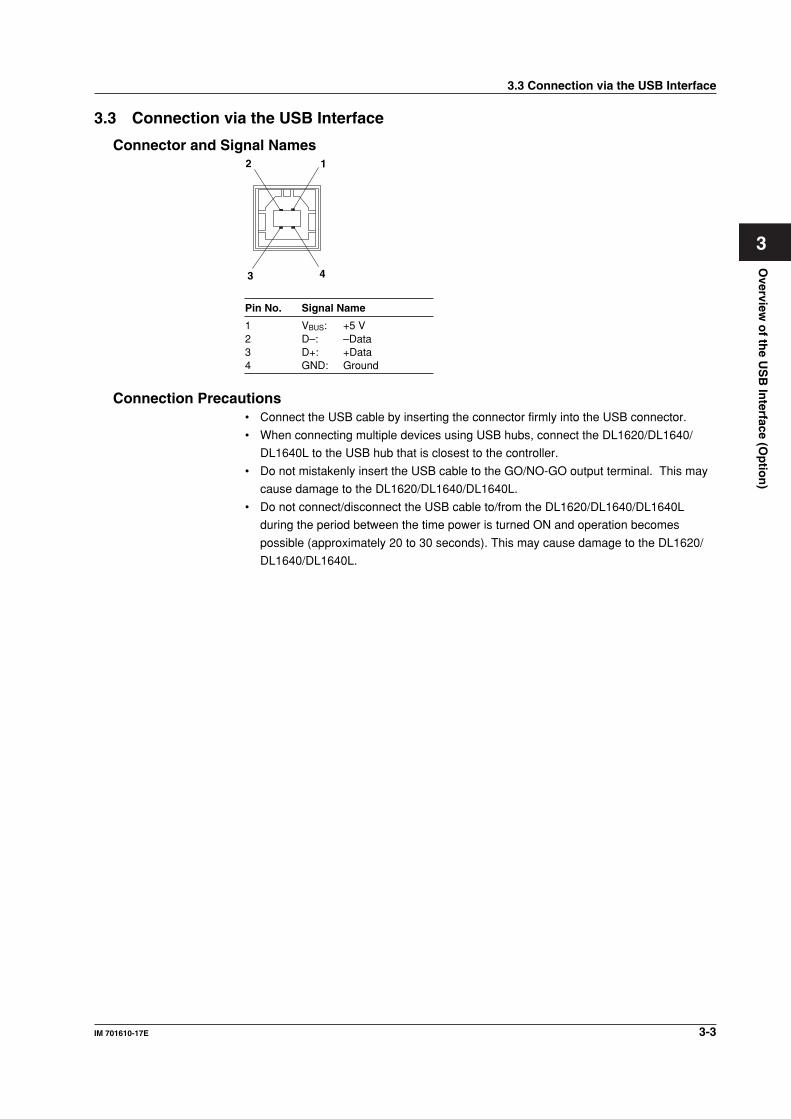
Connector and Signal Names12
43
Pin No. Signal Name
1 VBUS: +5 V2 D–: –Data3 D+: +Data4 GND: Ground
Connection Precautions• Connect the USB cable by inserting the connector firmly into the USB connector.
• When connecting multiple devices using USB hubs, connect the DL1620/DL1640/
DL1640L to the USB hub that is closest to the controller.
• Do not mistakenly insert the USB cable to the GO/NO-GO output terminal. This may
cause damage to the DL1620/DL1640/DL1640L.
• Do not connect/disconnect the USB cable to/from the DL1620/DL1640/DL1640L
during the period between the time power is turned ON and operation becomes
possible (approximately 20 to 30 seconds). This may cause damage to the DL1620/
DL1640/DL1640L.
3.3 Connection via the USB Interface
3-4 IM 701610-17E
3.4 Setting up this Instrument (USB)
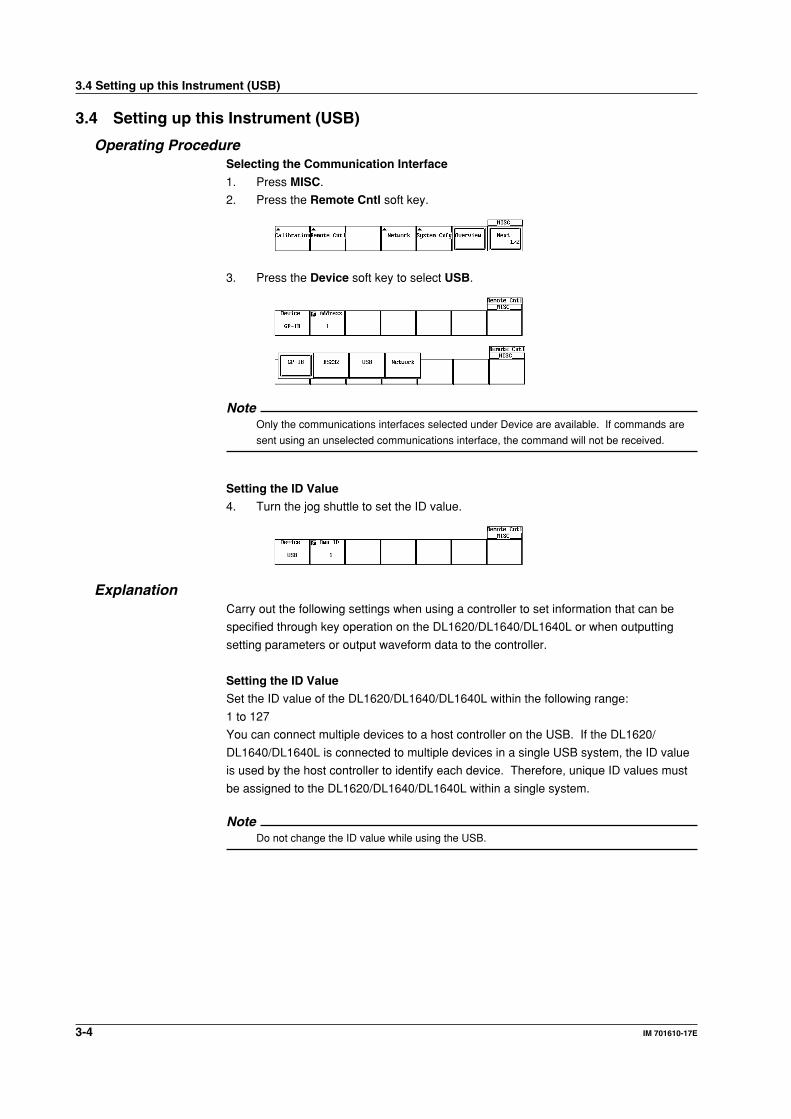
Operating ProcedureSelecting the Communication Interface
1. Press MISC.
2. Press the Remote Cntl soft key.
3. Press the Device soft key to select USB.
NoteOnly the communications interfaces selected under Device are available. If commands are
sent using an unselected communications interface, the command will not be received.
Setting the ID Value
4. Turn the jog shuttle to set the ID value.
ExplanationCarry out the following settings when using a controller to set information that can be
specified through key operation on the DL1620/DL1640/DL1640L or when outputting
setting parameters or output waveform data to the controller.
Setting the ID Value
Set the ID value of the DL1620/DL1640/DL1640L within the following range:
1 to 127
You can connect multiple devices to a host controller on the USB. If the DL1620/
DL1640/DL1640L is connected to multiple devices in a single USB system, the ID value
is used by the host controller to identify each device. Therefore, unique ID values must
be assigned to the DL1620/DL1640/DL1640L within a single system.
NoteDo not change the ID value while using the USB.
3.4 Setting up this Instrument (USB)
4-1IM 701610-17E
Overview
of th
e Eth
ernet In
terface (Op
tion
)
4
Chapter 4 Overview of the Ethernet Interface(Option)
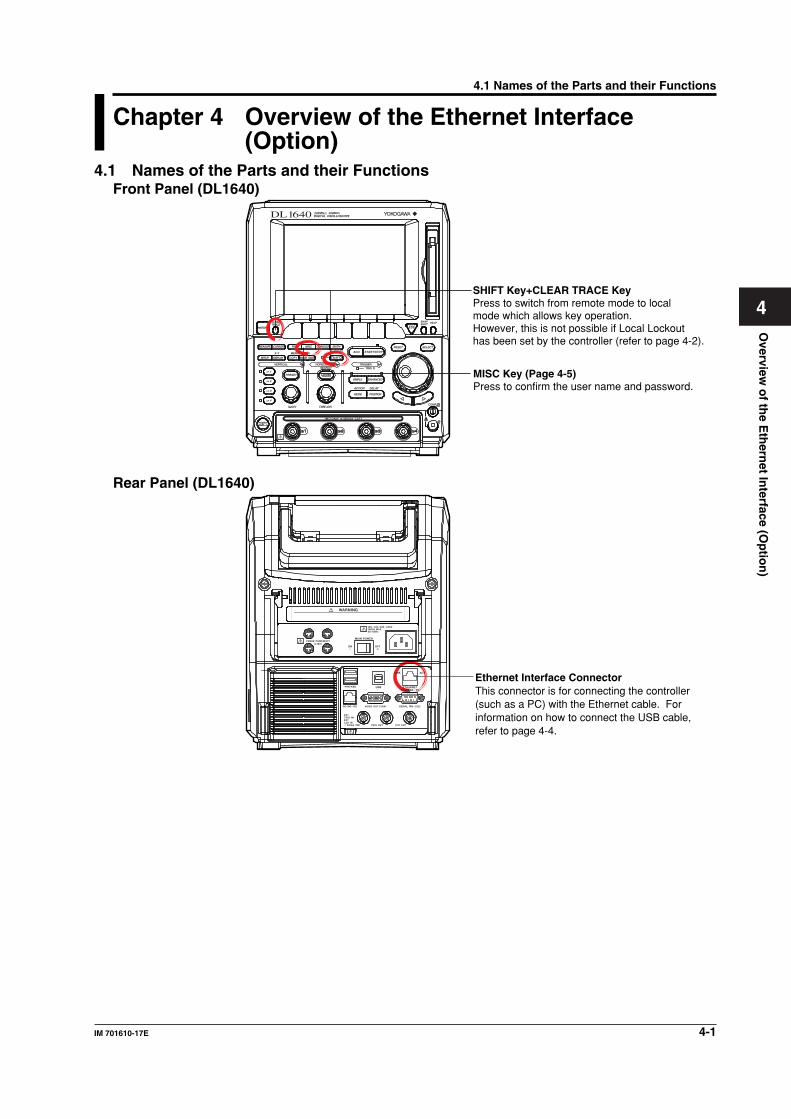
4.1 Names of the Parts and their FunctionsFront Panel (DL1640)
SHIFT Key+CLEAR TRACE KeyPress to switch from remote mode to local mode which allows key operation. However, this is not possible if Local Lockout has been set by the controller (refer to page 4-2).
MISC Key (Page 4-5)Press to confirm the user name and password.
HELP
SELECTRESET
SIMPLE
ACTION DELAY
MODE POSITION
MATHMISCFILE
COPY
CLEARTRACE
HISTORY
MEASURE
PRESET
CURSOR
X - Y
CH 1
CH 2
CH 3
CH 4
V DIV
POWER
TIME DIV
MENU
IMAGE SAVE
MENUPHASE
SHIFT
ZOOM
SEARCHHORIZONTALVERTICAL
GO/NOGO
COMP
ENHANCED
ACQ START/STOP
TRIGGERTRIG D
SNAPSHOT
SETUP DISPLAY
Rear Panel (DL1640)
Ethernet Interface ConnectorThis connector is for connecting the controller (such as a PC) with the Ethernet cable. For information on how to connect the USB cable, refer to page 4-4.
4.1 Names of the Parts and their Functions
4-2 IM 701610-17E
4.2 Ethernet Interface Functions and Specifications
Reception FunctionIt is possible to make the same settings via the RS-232 interface as can be made using
the front panel keys.
Measured or computed data, panel setup information, and error codes can be received.
Transmission FunctionMeasured/computed data can be output.
Panel setup information and the status byte can be output.
Error codes which have occurred can be output.
Ethernet Interface SpecificationsElectrical and Mechanical Specifications: IEEE802.3 Compliant
No. of simultaneous connections: 1
Port No.: 10001/tcp
Data Transfer RateThe table below shows approximate response times for output of waveform data,
assuming the following configuration.
Model: 701610
Controller: EPSON VZ-6000
Network Adaptor: Corega FEther PCI-TXL
Programming Language: Visual C++
Data Volume Byte Format Word Format ASCII Format
1000 approx. 9 ms approx. 10 ms approx. 191 ms10000 approx. 28 ms approx. 38 ms approx. 1.9 s100000 approx. 216 ms approx. 486 ms approx. 19 s1000000 approx. 2.3 s approx. 3 s approx. 187 s
Switching between Remote and Local ModeWhen Switched from Local to Remote
Remote mode is activated when the :COMMunicate:REMote ON command is received
from a controller while local mode is active.
• REMOTE is displayed on the upper right of the screen.
• All front panel keys except SHIFT +CLEAR TRACE can no longer be operated.
• Settings entered in local mode are retained even when switching to remote mode.
When Switched from Remote to Local Mode
Pressing SHIFT +CLEAR TRACE in remote mode puts the instrument in local mode.
However, this is not possible when the :COMMunicate:REMote ON command is
received from the computer while Local Lockout mode is active. Local mode is activated
when the :COMMunicate:REMote OFF command is received regardless of Local
Lockout.
• The REMOTE indicator on the upper right of the screen is turned off.
• All front panel keys are operative.
• Settings entered in remote mode are retained even when switching to local mode.
NoteThe Ethernet interface cannot be used simultaneously with other communications interfaces
(GP-IB, serial (RS-232), or USB).
4.2 Ethernet Interface Functions and Specifications
4-3IM 701610-17E
Overview
of th
e Eth
ernet In
terface (Op
tion
)
4
User Verification FunctionThe user must enter a user name and password for the Ethernet interface when
connecting to the network. The user name and password is set on the instrument in the
Remote Cntl setting screen under the MISC menu. For details, see section 4.4, “Setting
up this Instrument (Network).”
4.2 Ethernet Interface Functions and Specifications
4-4 IM 701610-17E
4.3 Connection via the Ethernet Interface
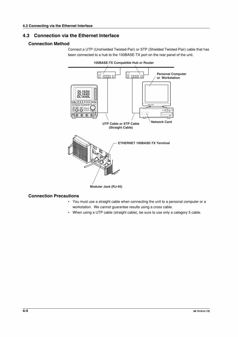
Connection MethodConnect a UTP (Unshielded Twisted-Pair) or STP (Shielded Twisted-Pair) cable that has
been connected to a hub to the 100BASE-TX port on the rear panel of the unit.
100BASE-TX Compatible Hub or Router
Personal Computeror Workstation
DL1620/DL1640/ DL1640L
UTP Cable or STP Cable(Straight Cable)
Network Card
ETHERNET 100BASE-TX Terminal
Modular Jack (RJ-45)
Connection Precautions• You must use a straight cable when connecting the unit to a personal computer or a
workstation. We cannot guarantee results using a cross cable.
• When using a UTP cable (straight cable), be sure to use only a category 5 cable.
4.3 Connecting via the Ethernet Interface
4-5IM 701610-17E
Overview
of th
e Eth
ernet In
terface (Op
tion
)
4
4.4 Setting up this Instrument (Network)
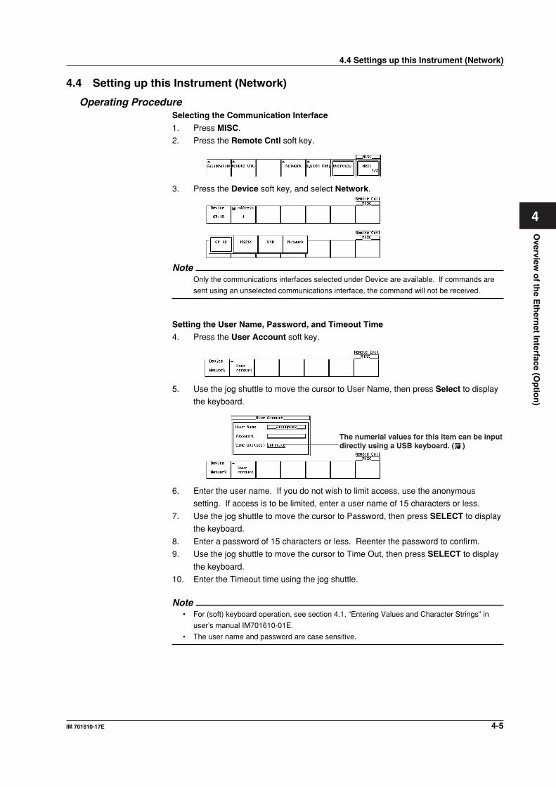
Operating ProcedureSelecting the Communication Interface
1. Press MISC.
2. Press the Remote Cntl soft key.
3. Press the Device soft key, and select Network.
NoteOnly the communications interfaces selected under Device are available. If commands are
sent using an unselected communications interface, the command will not be received.
Setting the User Name, Password, and Timeout Time
4. Press the User Account soft key.
5. Use the jog shuttle to move the cursor to User Name, then press Select to display
the keyboard.
The numerial values for this item can be inputdirectly using a USB keyboard. ( )
6. Enter the user name. If you do not wish to limit access, use the anonymous
setting. If access is to be limited, enter a user name of 15 characters or less.
7. Use the jog shuttle to move the cursor to Password, then press SELECT to display
the keyboard.
8. Enter a password of 15 characters or less. Reenter the password to confirm.
9. Use the jog shuttle to move the cursor to Time Out, then press SELECT to display
the keyboard.
10. Enter the Timeout time using the jog shuttle.
Note• For (soft) keyboard operation, see section 4.1, “Entering Values and Character Strings” in
user’s manual IM701610-01E.
• The user name and password are case sensitive.
4.4 Settings up this Instrument (Network)
4-6 IM 701610-17E
TCP/IP Settings
The following TCP/IP settings must be entered in order to use the Ethernet interface
functions.
• IP Address
• Subnet Mask
• Default Gateway
For details about how to enter these settings, see section 13.2, “Configuring the Ethernet
Interface (TCP/IP)” in user’s manual IM701610-01E.
DescriptionUse the settings below to setup communications so that you can input settings on the
instrument using the controller, or output settings or values to the controller.
Setting the User Name and Password
There is a user verification function for the Ethernet interface. The user name and
password are set on the instrument ahead of time.
• User Name Setting
15 characters or less may be used. The default value is anonymous.
• Password Setting
15 characters or less may be used.
Setting the Timeout Time
If the unit is not being accessed at the specified timeout time, the connection to the
network will be automatically closed.
TCP/IP Settings
For details, see section 13.2, “Configuring the Ethernet Interface (TCP/IP)” in user’s
manual IM701610-01E.
Note• If a user verification error occurs, the connection to the instrument is cut.
• If the login name is anonymous, it is not necessary to enter a password.
• When changing the user name, password, timeout time, or TCP/IP settings, the settings will
not take effect until the unit is turned OFF then back ON again.
4.4 Settings up this Instrument (Network)
5-1IM 701610-17E
Befo
re Pro
gram
min
g
5
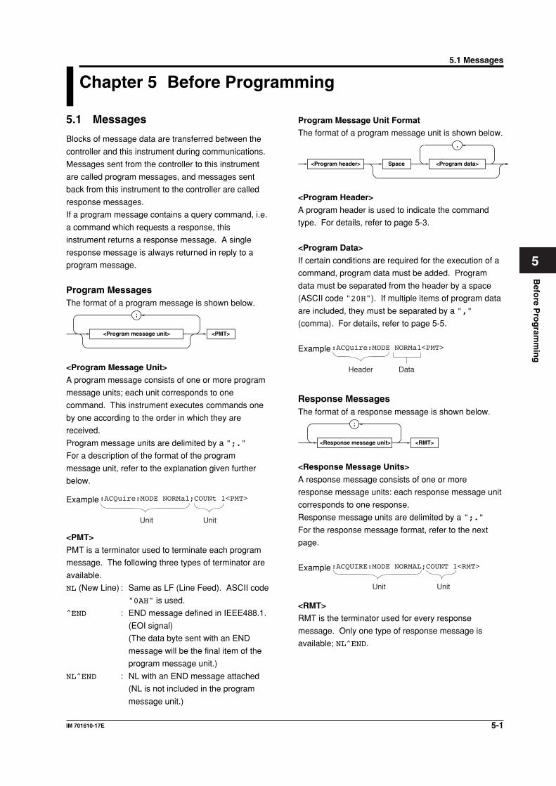
Program Message Unit Format
The format of a program message unit is shown below.,
<Program header> <Program data>Space
<Program Header>
A program header is used to indicate the command
type. For details, refer to page 5-3.
<Program Data>
If certain conditions are required for the execution of a
command, program data must be added. Program
data must be separated from the header by a space
(ASCII code "20H"). If multiple items of program data
are included, they must be separated by a ","
(comma). For details, refer to page 5-5.
Example:ACQuire:MODE NORMal<PMT>
Header Data
Response MessagesThe format of a response message is shown below.
<RMT>
;
<Response message unit>
<Response Message Units>
A response message consists of one or more
response message units: each response message unit
corresponds to one response.
Response message units are delimited by a ";."
For the response message format, refer to the next
page.
Example
Unit Unit
:ACQUIRE:MODE NORMAL;COUNT 1<RMT>
<RMT>
RMT is the terminator used for every response
message. Only one type of response message is
available; NL^END.
5.1 Messages
Blocks of message data are transferred between the
controller and this instrument during communications.
Messages sent from the controller to this instrument
are called program messages, and messages sent
back from this instrument to the controller are called
response messages.
If a program message contains a query command, i.e.
a command which requests a response, this
instrument returns a response message. A single
response message is always returned in reply to a
program message.
Program MessagesThe format of a program message is shown below.
<PMT>
;
<Program message unit>
<Program Message Unit>
A program message consists of one or more program
message units; each unit corresponds to one
command. This instrument executes commands one
by one according to the order in which they are
received.
Program message units are delimited by a ";."
For a description of the format of the program
message unit, refer to the explanation given further
below.
Example
Unit Unit
:ACQuire:MODE NORMal;COUNt 1<PMT>
<PMT>
PMT is a terminator used to terminate each program
message. The following three types of terminator are
available.
NL (New Line) : Same as LF (Line Feed). ASCII code
"0AH" is used.
^END : END message defined in IEEE488.1.
(EOI signal)
(The data byte sent with an END
message will be the final item of the
program message unit.)
NL^END : NL with an END message attached
(NL is not included in the program
message unit.)
Chapter 5 Before Programming5.1 Messages
5-2 IM 701610-17E
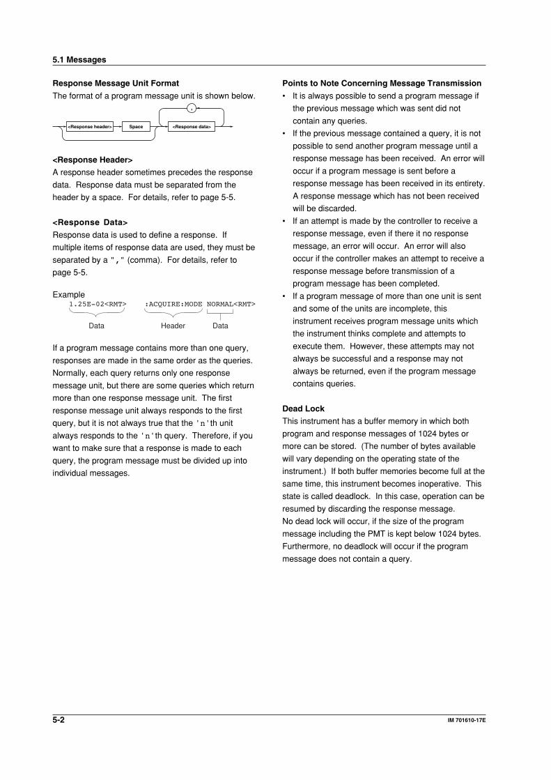
Response Message Unit Format
The format of a program message unit is shown below.,
<Response header> <Response data>Space
<Response Header>
A response header sometimes precedes the response
data. Response data must be separated from the
header by a space. For details, refer to page 5-5.
<Response Data>
Response data is used to define a response. If
multiple items of response data are used, they must be
separated by a "," (comma). For details, refer to
page 5-5.
Example1.25E-02<RMT> :ACQUIRE:MODE NORMAL<RMT>
Header Data Data
If a program message contains more than one query,
responses are made in the same order as the queries.
Normally, each query returns only one response
message unit, but there are some queries which return
more than one response message unit. The first
response message unit always responds to the first
query, but it is not always true that the 'n'th unit
always responds to the 'n'th query. Therefore, if you
want to make sure that a response is made to each
query, the program message must be divided up into
individual messages.
Points to Note Concerning Message Transmission
• It is always possible to send a program message if
the previous message which was sent did not
contain any queries.
• If the previous message contained a query, it is not
possible to send another program message until a
response message has been received. An error will
occur if a program message is sent before a
response message has been received in its entirety.
A response message which has not been received
will be discarded.
• If an attempt is made by the controller to receive a
response message, even if there it no response
message, an error will occur. An error will also
occur if the controller makes an attempt to receive a
response message before transmission of a
program message has been completed.
• If a program message of more than one unit is sent
and some of the units are incomplete, this
instrument receives program message units which
the instrument thinks complete and attempts to
execute them. However, these attempts may not
always be successful and a response may not
always be returned, even if the program message
contains queries.
Dead Lock
This instrument has a buffer memory in which both
program and response messages of 1024 bytes or
more can be stored. (The number of bytes available
will vary depending on the operating state of the
instrument.) If both buffer memories become full at the
same time, this instrument becomes inoperative. This
state is called deadlock. In this case, operation can be
resumed by discarding the response message.
No dead lock will occur, if the size of the program
message including the PMT is kept below 1024 bytes.
Furthermore, no deadlock will occur if the program
message does not contain a query.
5.1 Messages
5-3IM 701610-17E
Befo
re Pro
gram
min
g
5
When Concatenating Commands
Command Group
A command group is a group of commands which have
the same compound header. A command group may
contain sub-groups.
Example Commands relating to acquisition settings
:ACQuire:AVERage:COUNt
:ACQuire:MODE
:ACQuire:AVERage:EWEight
:ACQuire:REPetitive
:ACQuire:CLOCK
:ACQuire:RLENgth
:ACQuire:COUNt
:ACQuire:RESolution
When Concatenating Commands of the Same
Group
This instrument stores the hierarchical level of the
command which is currently being executed, and
performs analysis on the assumption that the next
command to be sent will also belong to the same level.
Therefore, it is possible to omit the header if the
commands belong to the same group.
Example :ACQuire:MODE NORMal;
COUNt 1<PMT>
When Concatenating Commands of Different
Groups
A colon (:) must be included before the header of a
command, if the command does not belong to the
same group as the preceding command. It is
impossible to omit a colon (:).
Example :ACQuire:MODE NORMal;:DISPlay:
FORMat SINGle<PMT>
When Concatenating Simple Headers
When you type in a simple header after another
command, you must include a colon (:) before the
simple header. It is impossible to omit a colon (:).
Example :ACQuire:MODE NORMal;:STARt<PMT>
When Concatenating Common Commands
Common commands defined in IEEE 488.2-1987 are
independent of hierarchical level. Thus, it is not
necessary to add a colon (:) before a common
command.
Example :ACQuire:MODE NORMal;*CLS;
COUNt 1<PMT>
5.2 Commands
There are three types of command (program header)
which can be sent from the controller to this
instrument. They differ in the format of their program
headers.
They are
• Common command header
• Compound header
• Simple header
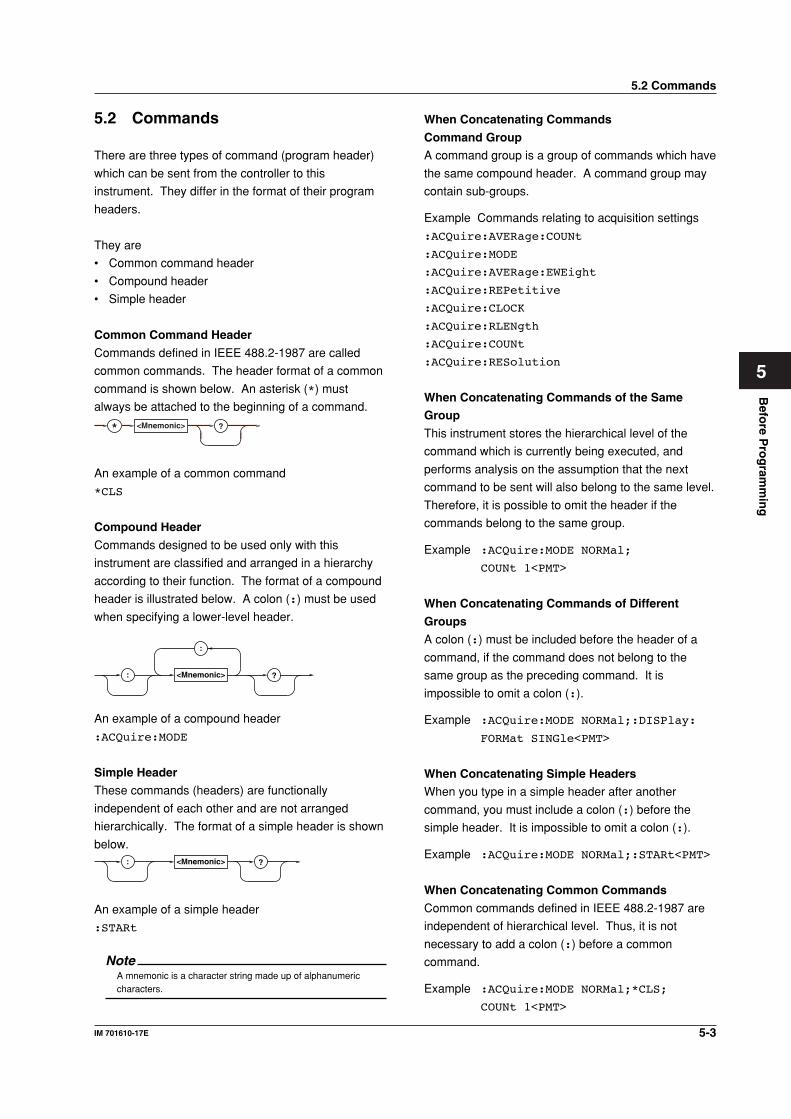
Common Command Header
Commands defined in IEEE 488.2-1987 are called
common commands. The header format of a common
command is shown below. An asterisk (*) must
always be attached to the beginning of a command.
* <Mnemonic> ?
An example of a common command
*CLS
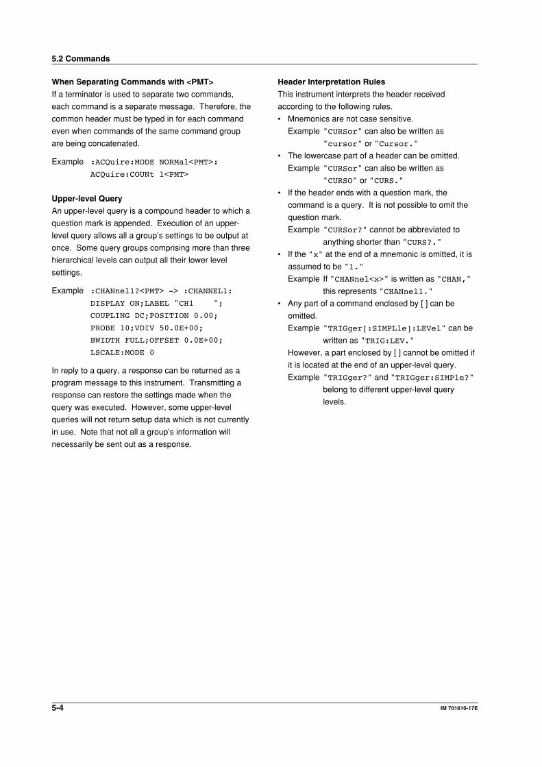
Compound Header
Commands designed to be used only with this
instrument are classified and arranged in a hierarchy
according to their function. The format of a compound
header is illustrated below. A colon (:) must be used
when specifying a lower-level header.
:
<Mnemonic> ?:
An example of a compound header
:ACQuire:MODE
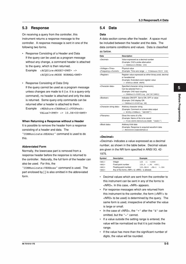
Simple Header
These commands (headers) are functionally
independent of each other and are not arranged
hierarchically. The format of a simple header is shown
below.<Mnemonic> ?:
An example of a simple header
:STARt
NoteA mnemonic is a character string made up of alphanumericcharacters.
5.2 Commands
5-4 IM 701610-17E
Header Interpretation Rules
This instrument interprets the header received
according to the following rules.
• Mnemonics are not case sensitive.
Example "CURSor" can also be written as
"cursor" or "Cursor."
• The lowercase part of a header can be omitted.
Example "CURSor" can also be written as
"CURSO" or "CURS."
• If the header ends with a question mark, the
command is a query. It is not possible to omit the
question mark.
Example "CURSor?" cannot be abbreviated to
anything shorter than "CURS?."
• If the "x" at the end of a mnemonic is omitted, it is
assumed to be "1."
Example If "CHANnel<x>" is written as "CHAN,"
this represents "CHANnel1."
• Any part of a command enclosed by [ ] can be
omitted.
Example "TRIGger[:SIMPLle]:LEVel" can be
written as "TRIG:LEV."
However, a part enclosed by [ ] cannot be omitted if
it is located at the end of an upper-level query.
Example "TRIGger?" and "TRIGger:SIMPle?"
belong to different upper-level query
levels.
When Separating Commands with <PMT>
If a terminator is used to separate two commands,
each command is a separate message. Therefore, the
common header must be typed in for each command
even when commands of the same command group
are being concatenated.
Example :ACQuire:MODE NORMal<PMT>:
ACQuire:COUNt 1<PMT>
Upper-level Query
An upper-level query is a compound header to which a
question mark is appended. Execution of an upper-
level query allows all a group’s settings to be output at
once. Some query groups comprising more than three
hierarchical levels can output all their lower level
settings.
Example :CHANnel1?<PMT> -> :CHANNEL1:
DISPLAY ON;LABEL "CH1 ";
COUPLING DC;POSITION 0.00;
PROBE 10;VDIV 50.0E+00;
BWIDTH FULL;OFFSET 0.0E+00;
LSCALE:MODE 0
In reply to a query, a response can be returned as a
program message to this instrument. Transmitting a
response can restore the settings made when the
query was executed. However, some upper-level
queries will not return setup data which is not currently
in use. Note that not all a group’s information will
necessarily be sent out as a response.
5.2 Commands
5-5IM 701610-17E
Befo
re Pro
gram
min
g
5
5.3 Response
On receiving a query from the controller, this
instrument returns a response message to the
controller. A response message is sent in one of the
following two forms.
• Response Consisting of a Header and Data
If the query can be used as a program message
without any change, a command header is attached
to the query, which is then returned.
Example :ACQUire:MODE?<PMT> ->
:ACQUire:MODE NORMAL<RMT>
• Response Consisting of Data Only
If the query cannot be used as a program message
unless changes are made to it (i.e. it is a query-only
command), no header is attached and only the data
is returned. Some query-only commands can be
returned after a header is attached to them.
Example :MEASure:CHANnel1:PTOPeak:
VALue?<PMT> -> 10.0E+00<RMT>
When Returning a Response without a Header
It is possible to remove the header from a response
consisting of a header and data. The
"COMMunicate:HEADer" command is used to do
this.
Abbreviated Form
Normally, the lowercase part is removed from a
response header before the response is returned to
the controller. Naturally, the full form of the header can
also be used. For this, the
"COMMunicate:VERBose" command is used. The
part enclosed by [ ] is also omitted in the abbreviated
form.
5.4 Data
Data
A data section comes after the header. A space must
be included between the header and the data. The
data contains conditions and values. Data is classified
as below.
Data Description
<Decimal> Value expressed as a decimal number(Example: CH2’s probe attenuation -> CHANnel2:PROBe 100)
<Voltage><Time> Physical value<Frequency><Current> (Example: Time axis range -> TIMebase:TDIV 1US)
<Register> Register value expressed as either binary,octal, decimalor hexadecimal(Example: Extended event register value -> STATus:EESE #HFE)
<Character data> Specified character string (mnemonic).Can be selected from (Example: CH2 input coupling -> CHANnel2:COUPling AC|DC|GND)
<Boolean> Indicates ON/OFF. Set to ON, OFF or value(Example: CH2 display ON-> CHANnel2:DISPlay ON)
<Character string data> Arbitrary character string(Example: Comment on screen-data output -> HCOPy:COMMent "ABCDEF")
<Filename> Gives the name of a file.(Example: Name of file to be saved -> FILE:SAVE:WAVeform:NAME "CASE1")
<Block data> Arbitrary 8-bit data(Example: Response to acquired waveform data-> #800000010ABCDEFGHIJ)
<Decimal>
<Decimal> indicates a value expressed as a decimal
number, as shown in the table below. Decimal values
are given in the NR form specified in ANSI X3. 42-
1975.
Symbol Description Example
<NR1> Integer 125 –1 +1000
<NR2> Fixed point number 125.0 –.90 +001.
<NR3> Floating point number 125.0E+0 –9E–1 +.1E4
<NRf> Any of the forms <NR1> to <NR3> is allowed.
• Decimal values which are sent from the controller to
this instrument can be sent in any of the forms to
<NR3>. In this case, <NRf> appears.
• For response messages which are returned from
this instrument to the controller, the form (<NR1> to
<NR3> to be used) is determined by the query. The
same form is used, irrespective of whether the value
is large or small.
• In the case of <NR3>, the "+" after the "E" can be
omitted, but the "–" cannot.
• If a value outside the setting range is entered, the
value will be normalized so that it is just inside the
range.
• If the value has more than the significant number of
digits, the value will be rounded.
5.3 Response/5.4 Data
5-6 IM 701610-17E
<Register>
<Register> indicates an integer, and can be expressed
in hexadecimal, octal, or binary as well as as a decimal
number. <Register> is used when each bit of a value
has a particular meaning. <Register> is expressed in
one of the following forms.
Form Example
<NRf> 1
#H<Hexadecimal value made up of the digits 0 to 9, and A to F> #H0F
#Q<Octal value made up of the digits 0 to 7> #Q777
#B<Binary value made up of the digits 0 and 1> #B001100
• <Register> is not case sensitive.
• Response messages are always expressed as
<NR1>.
<Character Data>
<Character data> is a specified string of character data
(a mnemonic). It is mainly used to indicate options,
and is chosen from the character strings given in .
For interpretation rules, refer to “Header Interpretation
Rules” on page 5-4.
Form Example
AC|DC|GND AC
• As with a header, the "COMMunicate:VERBose"
command can be used to return a response
message in its full form. Alternatively, the
abbreviated form can be used.
• The "COMMunicate:HEADer" command does not
affect <character data>.
<Boolean>
<Boolean> is data which indicates ON or OFF, and is
expressed in one of the following forms.
Form Example
ON|OFF|<NRf> ON OFF 1 0
• When <Boolean> is expressed in <NRf> form, OFF
is selected if the rounded integer value is "0" and
ON is selected if the rounded integer is "Not 0."
• A response message is always "1" if the value is
ON and "0" if it is OFF.
<Voltage>, <Time>, <Frequency>, and <Current>
<Voltage>, <Time>, <Frequency> , and <Current>
indicate decimal values which have physical
significance. <Multiplier> or <Unit> can be attached to
<NRf>. They can be entered in any of the following
forms.
Form Example
<NRf><Multiplier><Unit> 5MV
<NRf><Unit> 5E-3V
<NRf><Multiplier> 5M
<NRf> 5E-3
<Multiplier>
Multipliers which can be used are shown below.
Symbol Word Description
EX Exa 1018
PE Peta 1015
T Tera 1012
G Giga 109
MA Mega 106
K Kilo 103
M Milli 10–3
U Micro 10–6
N Nano 10–9
P Pico 10–12
F Femto 10–15
A Atto 10–18
<Unit>
Units which can be used are shown below.
Symbol Word Description
V Volt VoltageS Second TimeHZ Hertz FrequencyMHZ Megahertz FrequencyA Ampere Current
• <Multiplier> and <Unit> are not case sensitive.
• "U" is used to indicate "µ."• "MA" is used for Mega (M) to distinguish it from
Milli, except for in the case of Megahertz, which is
expressed as "MHZ." Hence, it is not permissible
to use "M" (Milli) for Hertz.
• If both <Multiplier> and <Unit> are omitted, the
default unit will be used.
• Response messages are always expressed in
<NR3> form. Neither <Multiplier> nor <Unit> is
used, therefore the default unit is used.
5.4 Data
5-7IM 701610-17E
Befo
re Pro
gram
min
g
5
<Character String Data>
<Character string data> is not a specified character
string like <Character data>. It is an arbitrary
character string. A character string must be enclosed
in apostrophes (') or double quotation marks (").
Form Example
<Character string data> 'ABC' "IEEE488.2-1987"
• Response messages are always enclosed in double
quotation marks.
• If a character string contains a double quotation
mark ("), the double quotation mark will be replaced
by two concatenated double quotation marks ("").
This rule also applies to a single quotation mark
within a character string.
• <Character string data> is an arbitrary character
string, therefore this instrument assumes that the
remaining program message units are part of the
character string if no apostrophe (') or double
quotation mark (") is encountered. As a result, no
error will be detected if a quotation mark is omitted.
<Filename>
Gives the name of a file. The format is as follows.
Form Example
<NRf>|<Character data>|<Character string> 1 CASE "CASE"
• If you input an <NRf> value, the system converts
the value (after rounding to the nearest integer) to
the corresponding 8-character ASCII string. (If you
set the value to 1, the name becomes
"00000001".) Note that negative values are not
allowed.
• The first 12 characters of <Character Data> are
assigned as the file name.
• The first 16 characters of <Character String Data>
are assigned as the file name.
• Response messages always return filenames as
<character string> arguments.
5.4 Data
<Block Data>
<Block data> is arbitrary 8-bit data. <Block data> is
only used for response messages. Response
messages are expressed in the following form.
Form Example
#N<N-digit decimal value><Data byte string> #800000010ABCDEFGHIJ
• #N
Indicates that the data is <Block data>. "N" is an
ASCII character string number (digits) which
indicates the number of data bytes that follow.
• <N-digits decimal value>
Indicates the number of bytes of data. (Example:
00000010=10 bytes)
• <Data byte string>
The actual data. (Example: ABCDEFGHIJ)
• Data is comprised of 8-bit values (0 to 255). This
means that the ASCII code "0AH," which stands
for "NL," can also be a code used for data. Hence,
care must be taken when programming the
controller.
5-8 IM 701610-17E
5.5 Synchronization with theController
Overlap Commands and Sequential Commands
There are two kinds of command; overlap commands
and sequential commands. Execution of an overlap
command may start before execution of the previously
sent command is completed.
The "CHANnel1:VDIV" command, for example, is a
sequential command. Assume that you set a new V/
div value and immediately request return of the new
value, as follows:
:CHANnel1:VDIV 5V;VIDV?<PMT>
In this case, the oscilloscope always returns the
newest setting ("5V"). This is because it always
completes processing of the current sequential
command (in this case, "VDIV 5V") before moving on
to the next command ("VDIV?").
In contrast, assume that you begin a file load and then
immediately query the V/div value:
:FILE:LOAD:SETup:EXECute "CASE1";:
CHANnel1:VDIV?
Because "FILE:LOAD:SETup:EXECute "CASE1""
is an overlapped command, the oscilloscope will
advance to the "CHANNel1:VDIV?" command before
it finishes the load. The returned V/div value will not
show the newest setting, but will rather show the
setting in use before the setup was changed.
Obviously, use of overlapped commands may in some
cases produce inappropriate results. Where
necessary, you can avoid such problems as described
below.
Synchronization with an Overlap Command
Using the *WAI Command
The *WAI command causes the commands which
follow it to wait until an overlap command has been
executed.
Example :COMMunicate:OPSE #0040;:FILE:
LOAD:SETup:EXECute "CASE1";
*WAI;:CHANnel1:VDIV?<PMT>
The "COMMunicate:OPSE" command is used to
designate which commands are to be subject to the
*WAI command. In the above example, only auto
setup is designated.
Since a *WAI command is executed just before
"CHANnel1:VDIV?," "CHANnel1:VDIV?" will not
be executed until auto setup has been completed.
Using the COMMunicate:OVERlap Command
The "COMMunicate:OVERlap" command is used to
enable or disable overlap operation.
Example :COMMunicate:OVERlap #HFFBF;:
FILE:LOAD:SETup:
EXECute "CASE1";:CHANnel1:VDIV:
VALue?<PMT>
The "COMMunicate:OVERlap #HFFBF" command
disables overlapped operation of the medium access
command, while enabling all other overlap-type
operations. The oscilloscope will therefore handle
"FILE:LOAD:SETup:EXECute "CASE1"" as
sequential command, ensuring that the
"CHANnel1:VIDV?" command (in the above
example) will not execute until file loading is
completed.
Using the *OPC Command
The *OPC command causes the OPC bit (bit 0) of the
standard event register (page 7-3) to be set to "1"
when an overlap operation has been completed.
Example :COMMunicate:OPSE #H0040;*ESE 1;
*ESR?;*SRE 32;:FILE:LOAD:SETup:
EXECute "CASE1";*OPC<PMT>
(Response to *ESR? is decoded.)
(Service request is awaited.)
CHANnel1:VDIV?<PMT>
The "COMMunicate:OPSE" command is used to
designate which commands are to be subject to the
*OPC command. In the above example, only medium
access commands are designated.
*ESE 1 and *SRE 32 stipulate that a service request
is generated only when the OPC bit is set to "1."
*ESR? is used to clear the standard event register.
In the above example, "CHANnel1:VDIV?" will not
be executed until a service request is generated.
5.5 Synchronization with the Controller
5-9IM 701610-17E
Befo
re Pro
gram
min
g
5
5.5 Synchronization with the Controller
Using the *OPC? Query
The *OPC? query generates a response when an
overlap operation has been completed.
Example :COMMunicate:OPSE #H0040;:FILE:
LOAD:SETup:EXECute "CASE1";
*OPC?<PMT>
(Response to *OPC? is decoded.)
:CHANnel1:VDIV?<PMT>
The "COMMunicate:OPSE" command is used to
designate which commands are to be subject to the
*OPC? command. In the above example, only medium
access commands are designated.
Since *OPC? does not generate a response until an
overlap operation is completed, file loading will have
been completed when a response to *OPC? is read.
NoteMost commands are sequential commands. Commands used inChapter 6 are sequential commands unless otherwise specified.
Synchronization with Non-Overlap Commands
Synchronization is sometimes required for reasons
other than communications-related reasons, such as
the activation of a trigger, even if a sequential
command is used.
For example, if a “next program” message is
transmitted to make an inquiry about the waveform
data which has been acquired using single mode as
the trigger mode, the "WAVeform:SEND?" command
is sometimes executed whether acquisition has been
completed or not, causing a command execution error.
:TRIGger:MODE SINGle;:STARt;:WAVeform:
SEND?<PMT>
In this case, synchronization with the time at which
acquisition is completed must be accomplished, as
shown next.
Using STATus:CONDition? Query
A "STATus:CONDition?" query is used to make an
query about the contents of the condition register
(page 7-4). It is possible to judge whether acquisition
is in progress or not by reading bit 0 of the condition
register. Bit 0 is "1" if acquisition is in progress, and
"0" if acquisition is stopped.
Example :TRIGger:MODE SINGle;:STARt<PMT>
:STATus:CONDition?<PMT>
(Returns to the previous status if bit 0 is
found to be "1" when the response is
decoded.)
:WAVeform:SEND?<PMT>
A "WAVeform:SEND?" query will not be executed
until bit 0 of the condition register has been set to
"0."
Using the Extended Event Register
Changes in the condition register are reflected in the
extended event register (page 7-4).
Example :STATus:FILTer1
FALL;:STATus:EESE 1;EESR?;
*SRE 8;:TRIGger:MODE SINGle;:
STARt<PMT>
(Response to "STATus:EESR?" is
decoded.)
(Service request is awaited.)
:WAVeform:SEND?<PMT>
The "STATus:FILTer1 FALL" command sets the
transition filter such that Bit 0 (FILTer1) of the
Extended Event Register sets to 1 when Bit 0 of the
Condition Register changes from 1 to 0.
"STATus:EESE 1" is a command used only to reflect
the status of bit 0 of the extended event register in the
status byte.
"STATus:EESR?" is used to clear the extended event
register.
The *SRE command is used to generate a service
request caused solely by the extended event register.
"WAVeform:SEND?" will not be executed until a
service request is generated.
Using the COMMunicate:WAIT Command
The "COMMunicate:WAIT" command halts
communications until a specific event is generated.
Example :STATus:FILTer1 FALL;:STATus:
EESR?;:TRIGger:MODE SINGle;:
STARt<PMT>
(Response to "STATus:EESR?" is
decoded.)
:COMMunicate:WAIT 1;:WAVeform:
SEND?<PMT>
For a description of "STATus:FILTer1 FALL" and
"STATus:EESR?," refer to “Using the extended event
register” on this page.
"COMMunicate:WAIT 1" means that
communications is halted until bit 0 of the extended
event register is set to "1."
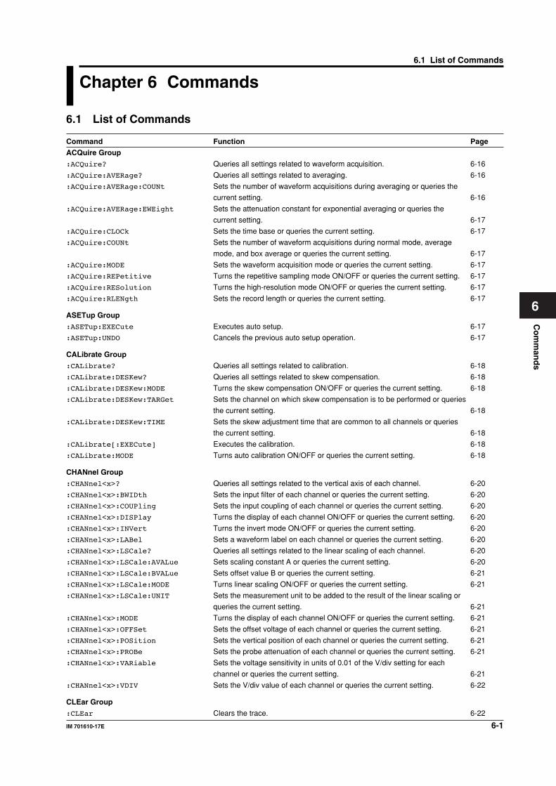
Co
mm
and
s
6-1IM 701610-17E
6
Chapter 6 Commands
6.1 List of Commands
Command Function Page
ACQuire Group
:ACQuire? Queries all settings related to waveform acquisition. 6-16
:ACQuire:AVERage? Queries all settings related to averaging. 6-16
:ACQuire:AVERage:COUNt Sets the number of waveform acquisitions during averaging or queries the
current setting. 6-16
:ACQuire:AVERage:EWEight Sets the attenuation constant for exponential averaging or queries the
current setting. 6-17
:ACQuire:CLOCk Sets the time base or queries the current setting. 6-17
:ACQuire:COUNt Sets the number of waveform acquisitions during normal mode, average
mode, and box average or queries the current setting. 6-17
:ACQuire:MODE Sets the waveform acquisition mode or queries the current setting. 6-17
:ACQuire:REPetitive Turns the repetitive sampling mode ON/OFF or queries the current setting. 6-17
:ACQuire:RESolution Turns the high-resolution mode ON/OFF or queries the current setting. 6-17
:ACQuire:RLENgth Sets the record length or queries the current setting. 6-17
ASETup Group
:ASETup:EXECute Executes auto setup. 6-17
:ASETup:UNDO Cancels the previous auto setup operation. 6-17
CALibrate Group
:CALibrate? Queries all settings related to calibration. 6-18
:CALibrate:DESKew? Queries all settings related to skew compensation. 6-18
:CALibrate:DESKew:MODE Turns the skew compensation ON/OFF or queries the current setting. 6-18
:CALibrate:DESKew:TARGet Sets the channel on which skew compensation is to be performed or queries
the current setting. 6-18
:CALibrate:DESKew:TIME Sets the skew adjustment time that are common to all channels or queries
the current setting. 6-18
:CALibrate[:EXECute] Executes the calibration. 6-18
:CALibrate:MODE Turns auto calibration ON/OFF or queries the current setting. 6-18
CHANnel Group
:CHANnel<x>? Queries all settings related to the vertical axis of each channel. 6-20
:CHANnel<x>:BWIDth Sets the input filter of each channel or queries the current setting. 6-20
:CHANnel<x>:COUPling Sets the input coupling of each channel or queries the current setting. 6-20
:CHANnel<x>:DISPlay Turns the display of each channel ON/OFF or queries the current setting. 6-20
:CHANnel<x>:INVert Turns the invert mode ON/OFF or queries the current setting. 6-20
:CHANnel<x>:LABel Sets a waveform label on each channel or queries the current setting. 6-20
:CHANnel<x>:LSCale? Queries all settings related to the linear scaling of each channel. 6-20
:CHANnel<x>:LSCale:AVALue Sets scaling constant A or queries the current setting. 6-20
:CHANnel<x>:LSCale:BVALue Sets offset value B or queries the current setting. 6-21
:CHANnel<x>:LSCale:MODE Turns linear scaling ON/OFF or queries the current setting. 6-21
:CHANnel<x>:LSCale:UNIT Sets the measurement unit to be added to the result of the linear scaling or
queries the current setting. 6-21
:CHANnel<x>:MODE Turns the display of each channel ON/OFF or queries the current setting. 6-21
:CHANnel<x>:OFFSet Sets the offset voltage of each channel or queries the current setting. 6-21
:CHANnel<x>:POSition Sets the vertical position of each channel or queries the current setting. 6-21
:CHANnel<x>:PROBe Sets the probe attenuation of each channel or queries the current setting. 6-21
:CHANnel<x>:VARiable Sets the voltage sensitivity in units of 0.01 of the V/div setting for each
channel or queries the current setting. 6-21
:CHANnel<x>:VDIV Sets the V/div value of each channel or queries the current setting. 6-22
CLEar Group
:CLEar Clears the trace. 6-22
6.1 List of Commands
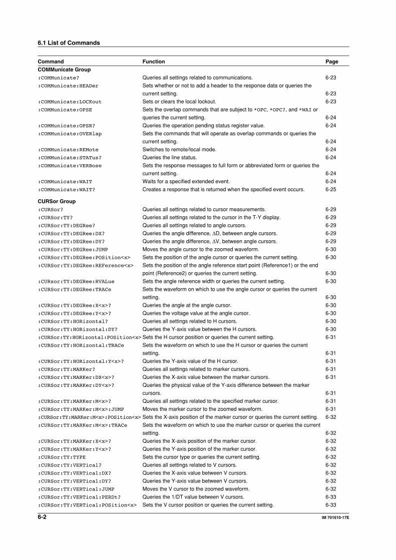
6-2 IM 701610-17E
6.1 List of Commands
Command Function Page
COMMunicate Group
:COMMunicate? Queries all settings related to communications. 6-23
:COMMunicate:HEADer Sets whether or not to add a header to the response data or queries the
current setting. 6-23
:COMMunicate:LOCKout Sets or clears the local lockout. 6-23
:COMMunicate:OPSE Sets the overlap commands that are subject to *OPC, *OPC?, and *WAI or
queries the current setting. 6-24
:COMMunicate:OPSR? Queries the operation pending status register value. 6-24
:COMMunicate:OVERlap Sets the commands that will operate as overlap commands or queries the
current setting. 6-24
:COMMunicate:REMote Switches to remote/local mode. 6-24
:COMMunicate:STATus? Queries the line status. 6-24
:COMMunicate:VERBose Sets the response messages to full form or abbreviated form or queries the
current setting. 6-24
:COMMunicate:WAIT Waits for a specified extended event. 6-24
:COMMunicate:WAIT? Creates a response that is returned when the specified event occurs. 6-25
CURSor Group
:CURSor? Queries all settings related to cursor measurements. 6-29
:CURSor:TY? Queries all settings related to the cursor in the T-Y display. 6-29
:CURSor:TY:DEGRee? Queries all settings related to angle cursors. 6-29
:CURSor:TY:DEGRee:DX? Queries the angle difference, ∆D, between angle cursors. 6-29
:CURSor:TY:DEGRee:DY? Queries the angle difference, ∆V, between angle cursors. 6-29
:CURSor:TY:DEGRee:JUMP Moves the angle cursor to the zoomed waveform. 6-30
:CURSor:TY:DEGRee:POSition<x> Sets the position of the angle cursor or queries the current setting. 6-30
:CURSor:TY:DEGRee:REFerence<x> Sets the position of the angle reference start point (Reference1) or the end
point (Reference2) or queries the current setting. 6-30
:CURsor:TY:DEGRee:RVALue Sets the angle reference width or queries the current setting. 6-30
:CURSor:TY:DEGRee:TRACe Sets the waveform on which to use the angle cursor or queries the current
setting. 6-30
:CURSor:TY:DEGRee:X<x>? Queries the angle at the angle cursor. 6-30
:CURSor:TY:DEGRee:Y<x>? Queries the voltage value at the angle cursor. 6-30
:CURSor:TY:HORizontal? Queries all settings related to H cursors. 6-30
:CURSor:TY:HORizontal:DY? Queries the Y-axis value between the H cursors. 6-30
:CURSor:TY:HORizontal:POSition<x>Sets the H cursor position or queries the current setting. 6-31
:CURSor:TY:HORizontal:TRACe Sets the waveform on which to use the H cursor or queries the current
setting. 6-31
:CURSor:TY:HORizontal:Y<x>? Queries the Y-axis value of the H cursor. 6-31
:CURSor:TY:MARKer? Queries all settings related to marker cursors. 6-31
:CURSor:TY:MARKer:DX<x>? Queries the X-axis value between the marker cursors. 6-31
:CURSor:TY:MARKer:DY<x>? Queries the physical value of the Y-axis difference between the marker
cursors. 6-31
:CURSor:TY:MARKer:M<x>? Queries all settings related to the specified marker cursor. 6-31
:CURSor:TY:MARKer:M<x>:JUMP Moves the marker cursor to the zoomed waveform. 6-31
:CURSor:TY:MARKer:M<x>:POSition<x> Sets the X-axis position of the marker cursor or queries the current setting. 6-32
:CURSor:TY:MARKer:M<x>:TRACe Sets the waveform on which to use the marker cursor or queries the current
setting. 6-32
:CURSor:TY:MARKer:X<x>? Queries the X-axis position of the marker cursor. 6-32
:CURSor:TY:MARKer:Y<x>? Queries the Y-axis position of the marker cursor. 6-32
:CURSor:TY:TYPE Sets the cursor type or queries the current setting. 6-32
:CURSor:TY:VERTical? Queries all settings related to V cursors. 6-32
:CURSor:TY:VERTical:DX? Queries the X-axis value between V cursors. 6-32
:CURSor:TY:VERTical:DY? Queries the Y-axis value between V cursors. 6-32
:CURSor:TY:VERTical:JUMP Moves the V cursor to the zoomed waveform. 6-32
:CURSor:TY:VERTical:PERDt? Queries the 1/DT value between V cursors. 6-33
:CURSor:TY:VERTical:POSition<x> Sets the V cursor position or queries the current setting. 6-33
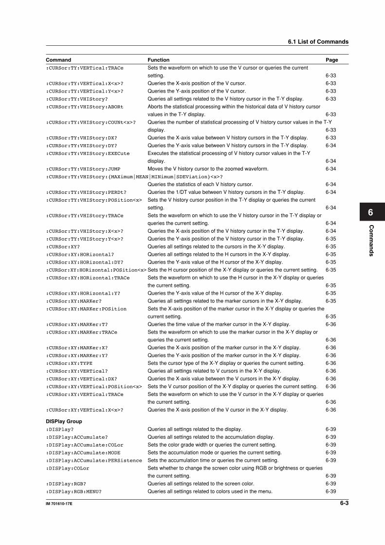
Co
mm
and
s
6-3IM 701610-17E
6
6.1 List of Commands
Command Function Page
:CURSor:TY:VERTical:TRACe Sets the waveform on which to use the V cursor or queries the current
setting. 6-33
:CURSor:TY:VERTical:X<x>? Queries the X-axis position of the V cursor. 6-33
:CURSor:TY:VERTical:Y<x>? Queries the Y-axis position of the V cursor. 6-33
:CURSor:TY:VHIStory? Queries all settings related to the V history cursor in the T-Y display. 6-33
:CURSor:TY:VHIStory:ABORt Aborts the statistical processing within the historical data of V history cursor
values in the T-Y display. 6-33
:CURSor:TY:VHIStory:COUNt<x>? Queries the number of statistical processing of V history cursor values in the T-Y
display. 6-33
:CURSor:TY:VHIStory:DX? Queries the X-axis value between V history cursors in the T-Y display. 6-33
:CURSor:TY:VHIStory:DY? Queries the Y-axis value between V history cursors in the T-Y display. 6-34
:CURSor:TY:VHIStory:EXECute Executes the statistical processing of V history cursor values in the T-Y
display. 6-34
:CURSor:TY:VHIStory:JUMP Moves the V history cursor to the zoomed waveform. 6-34
:CURSor:TY:VHIStory:MAXimum|MEAN|MINimum|SDEViation<x>?
Queries the statistics of each V history cursor. 6-34
:CURSor:TY:VHIStory:PERDt? Queries the 1/DT value between V history cursors in the T-Y display. 6-34
:CURSor:TY:VHIStory:POSition<x> Sets the V history cursor position in the T-Y display or queries the current
setting. 6-34
:CURSor:TY:VHIStory:TRACe Sets the waveform on which to use the V history cursor in the T-Y display or
queries the current setting. 6-34
:CURSor:TY:VHIStory:X<x>? Queries the X-axis position of the V history cursor in the T-Y display. 6-34
:CURSor:TY:VHIStory:Y<x>? Queries the Y-axis position of the V history cursor in the T-Y display. 6-35
:CURSor:XY? Queries all settings related to the cursors in the X-Y display. 6-35
:CURSor:XY:HORizontal? Queries all settings related to the H cursors in the X-Y display. 6-35
:CURSor:XY:HORizontal:DY? Queries the Y-axis value of the H cursor of the X-Y display. 6-35
:CURSor:XY:HORizontal:POSition<x>Sets the H cursor position of the X-Y display or queries the current setting. 6-35
:CURSor:XY:HORizontal:TRACe Sets the waveform on which to use the H cursor in the X-Y display or queries
the current setting. 6-35
:CURSor:XY:HORizontal:Y? Queries the Y-axis value of the H cursor of the X-Y display. 6-35
:CURSor:XY:MARKer? Queries all settings related to the marker cursors in the X-Y display. 6-35
:CURSor:XY:MARKer:POSition Sets the X-axis position of the marker cursor in the X-Y display or queries the
current setting. 6-35
:CURSor:XY:MARKer:T? Queries the time value of the marker cursor in the X-Y display. 6-36
:CURSor:XY:MARKer:TRACe Sets the waveform on which to use the marker cursor in the X-Y display or
queries the current setting. 6-36
:CURSor:XY:MARKer:X? Queries the X-axis position of the marker cursor in the X-Y display. 6-36
:CURSor:XY:MARKer:Y? Queries the Y-axis position of the marker cursor in the X-Y display. 6-36
:CURSor:XY:TYPE Sets the cursor type of the X-Y display or queries the current setting. 6-36
:CURSor:XY:VERTical? Queries all settings related to V cursors in the X-Y display. 6-36
:CURSor:XY:VERTical:DX? Queries the X-axis value between the V cursors in the X-Y display. 6-36
:CURSor:XY:VERTical:POSition<x> Sets the V cursor position of the X-Y display or queries the current setting. 6-36
:CURSor:XY:VERTical:TRACe Sets the waveform on which to use the V cursor in the X-Y display or queries
the current setting. 6-36
:CURSor:XY:VERTical:X<x>? Queries the X-axis position of the V cursor in the X-Y display. 6-36
DISPlay Group
:DISPlay? Queries all settings related to the display. 6-39
:DISPlay:ACCumulate? Queries all settings related to the accumulation display. 6-39
:DISPlay:ACCumulate:COLor Sets the color grade width or queries the current setting. 6-39
:DISPlay:ACCumulate:MODE Sets the accumulation mode or queries the current setting. 6-39
:DISPlay:ACCumulate:PERSistence Sets the accumulation time or queries the current setting. 6-39
:DISPlay:COLor Sets whether to change the screen color using RGB or brightness or queries
the current setting. 6-39
:DISPlay:RGB? Queries all settings related to the screen color. 6-39
:DISPlay:RGB:MENU? Queries all settings related to colors used in the menu. 6-39
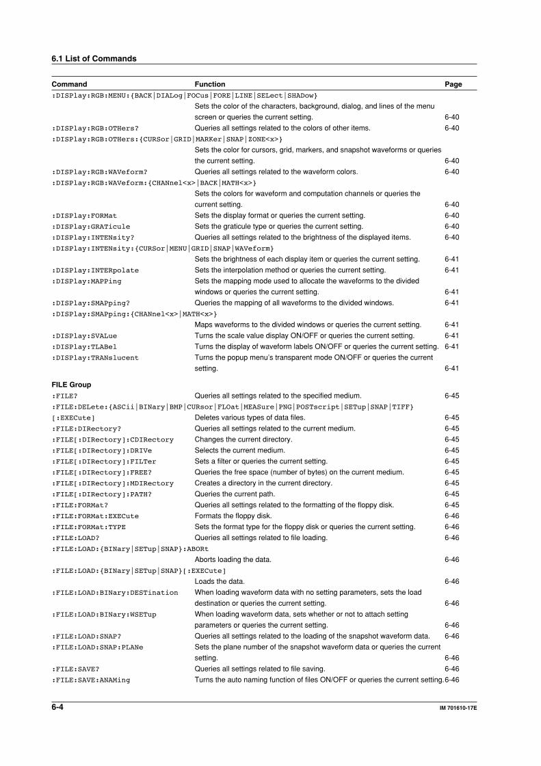
6-4 IM 701610-17E
Command Function Page
:DISPlay:RGB:MENU:BACK|DIALog|FOCus|FORE|LINE|SELect|SHADow
Sets the color of the characters, background, dialog, and lines of the menu
screen or queries the current setting. 6-40
:DISPlay:RGB:OTHers? Queries all settings related to the colors of other items. 6-40
:DISPlay:RGB:OTHers:CURSor|GRID|MARKer|SNAP|ZONE<x>
Sets the color for cursors, grid, markers, and snapshot waveforms or queries
the current setting. 6-40
:DISPlay:RGB:WAVeform? Queries all settings related to the waveform colors. 6-40
:DISPlay:RGB:WAVeform:CHANnel<x>|BACK|MATH<x>
Sets the colors for waveform and computation channels or queries the
current setting. 6-40
:DISPlay:FORMat Sets the display format or queries the current setting. 6-40
:DISPlay:GRATicule Sets the graticule type or queries the current setting. 6-40
:DISPlay:INTENsity? Queries all settings related to the brightness of the displayed items. 6-40
:DISPlay:INTENsity:CURSor|MENU|GRID|SNAP|WAVeform
Sets the brightness of each display item or queries the current setting. 6-41
:DISPlay:INTERpolate Sets the interpolation method or queries the current setting. 6-41
:DISPlay:MAPPing Sets the mapping mode used to allocate the waveforms to the divided
windows or queries the current setting. 6-41
:DISPlay:SMAPping? Queries the mapping of all waveforms to the divided windows. 6-41
:DISPlay:SMAPping:CHANnel<x>|MATH<x>
Maps waveforms to the divided windows or queries the current setting. 6-41
:DISPlay:SVALue Turns the scale value display ON/OFF or queries the current setting. 6-41
:DISPlay:TLABel Turns the display of waveform labels ON/OFF or queries the current setting. 6-41
:DISPlay:TRANslucent Turns the popup menu’s transparent mode ON/OFF or queries the current
setting. 6-41
FILE Group
:FILE? Queries all settings related to the specified medium. 6-45
:FILE:DELete:ASCii|BINary|BMP|CURsor|FLOat|MEASure|PNG|POSTscript|SETup|SNAP|TIFF
[:EXECute] Deletes various types of data files. 6-45
:FILE:DIRectory? Queries all settings related to the current medium. 6-45
:FILE[:DIRectory]:CDIRectory Changes the current directory. 6-45
:FILE[:DIRectory]:DRIVe Selects the current medium. 6-45
:FILE[:DIRectory]:FILTer Sets a filter or queries the current setting. 6-45
:FILE[:DIRectory]:FREE? Queries the free space (number of bytes) on the current medium. 6-45
:FILE[:DIRectory]:MDIRectory Creates a directory in the current directory. 6-45
:FILE[:DIRectory]:PATH? Queries the current path. 6-45
:FILE:FORMat? Queries all settings related to the formatting of the floppy disk. 6-45
:FILE:FORMat:EXECute Formats the floppy disk. 6-46
:FILE:FORMat:TYPE Sets the format type for the floppy disk or queries the current setting. 6-46
:FILE:LOAD? Queries all settings related to file loading. 6-46
:FILE:LOAD:BINary|SETup|SNAP:ABORt
Aborts loading the data. 6-46
:FILE:LOAD:BINary|SETup|SNAP[:EXECute]
Loads the data. 6-46
:FILE:LOAD:BINary:DESTination When loading waveform data with no setting parameters, sets the load
destination or queries the current setting. 6-46
:FILE:LOAD:BINary:WSETup When loading waveform data, sets whether or not to attach setting
parameters or queries the current setting. 6-46
:FILE:LOAD:SNAP? Queries all settings related to the loading of the snapshot waveform data. 6-46
:FILE:LOAD:SNAP:PLANe Sets the plane number of the snapshot waveform data or queries the current
setting. 6-46
:FILE:SAVE? Queries all settings related to file saving. 6-46
:FILE:SAVE:ANAMing Turns the auto naming function of files ON/OFF or queries the current setting.6-46
6.1 List of Commands
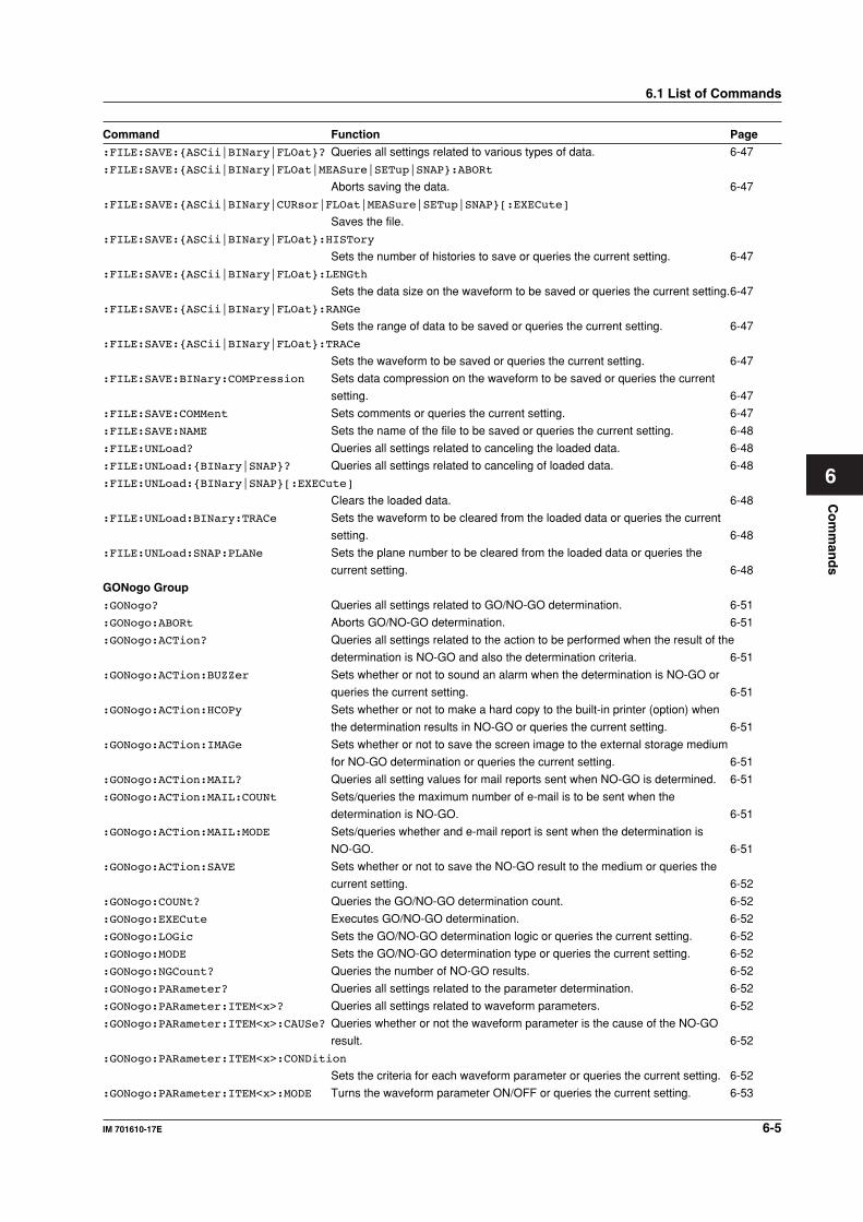
Co
mm
and
s
6-5IM 701610-17E
6
Command Function Page
:FILE:SAVE:ASCii|BINary|FLOat? Queries all settings related to various types of data. 6-47
:FILE:SAVE:ASCii|BINary|FLOat|MEASure|SETup|SNAP:ABORt
Aborts saving the data. 6-47
:FILE:SAVE:ASCii|BINary|CURsor|FLOat|MEASure|SETup|SNAP[:EXECute]
Saves the file.
:FILE:SAVE:ASCii|BINary|FLOat:HISTory
Sets the number of histories to save or queries the current setting. 6-47
:FILE:SAVE:ASCii|BINary|FLOat:LENGth
Sets the data size on the waveform to be saved or queries the current setting.6-47
:FILE:SAVE:ASCii|BINary|FLOat:RANGe
Sets the range of data to be saved or queries the current setting. 6-47
:FILE:SAVE:ASCii|BINary|FLOat:TRACe
Sets the waveform to be saved or queries the current setting. 6-47
:FILE:SAVE:BINary:COMPression Sets data compression on the waveform to be saved or queries the current
setting. 6-47
:FILE:SAVE:COMMent Sets comments or queries the current setting. 6-47
:FILE:SAVE:NAME Sets the name of the file to be saved or queries the current setting. 6-48
:FILE:UNLoad? Queries all settings related to canceling the loaded data. 6-48
:FILE:UNLoad:BINary|SNAP? Queries all settings related to canceling of loaded data. 6-48
:FILE:UNLoad:BINary|SNAP[:EXECute]
Clears the loaded data. 6-48
:FILE:UNLoad:BINary:TRACe Sets the waveform to be cleared from the loaded data or queries the current
setting. 6-48
:FILE:UNLoad:SNAP:PLANe Sets the plane number to be cleared from the loaded data or queries the
current setting. 6-48
GONogo Group
:GONogo? Queries all settings related to GO/NO-GO determination. 6-51
:GONogo:ABORt Aborts GO/NO-GO determination. 6-51
:GONogo:ACTion? Queries all settings related to the action to be performed when the result of the
determination is NO-GO and also the determination criteria. 6-51
:GONogo:ACTion:BUZZer Sets whether or not to sound an alarm when the determination is NO-GO or
queries the current setting. 6-51
:GONogo:ACTion:HCOPy Sets whether or not to make a hard copy to the built-in printer (option) when
the determination results in NO-GO or queries the current setting. 6-51
:GONogo:ACTion:IMAGe Sets whether or not to save the screen image to the external storage medium
for NO-GO determination or queries the current setting. 6-51
:GONogo:ACTion:MAIL? Queries all setting values for mail reports sent when NO-GO is determined. 6-51
:GONogo:ACTion:MAIL:COUNt Sets/queries the maximum number of e-mail is to be sent when the
determination is NO-GO. 6-51
:GONogo:ACTion:MAIL:MODE Sets/queries whether and e-mail report is sent when the determination is
NO-GO. 6-51
:GONogo:ACTion:SAVE Sets whether or not to save the NO-GO result to the medium or queries the
current setting. 6-52
:GONogo:COUNt? Queries the GO/NO-GO determination count. 6-52
:GONogo:EXECute Executes GO/NO-GO determination. 6-52
:GONogo:LOGic Sets the GO/NO-GO determination logic or queries the current setting. 6-52
:GONogo:MODE Sets the GO/NO-GO determination type or queries the current setting. 6-52
:GONogo:NGCount? Queries the number of NO-GO results. 6-52
:GONogo:PARameter? Queries all settings related to the parameter determination. 6-52
:GONogo:PARameter:ITEM<x>? Queries all settings related to waveform parameters. 6-52
:GONogo:PARameter:ITEM<x>:CAUSe? Queries whether or not the waveform parameter is the cause of the NO-GO
result. 6-52
:GONogo:PARameter:ITEM<x>:CONDition
Sets the criteria for each waveform parameter or queries the current setting. 6-52
:GONogo:PARameter:ITEM<x>:MODE Turns the waveform parameter ON/OFF or queries the current setting. 6-53
6.1 List of Commands
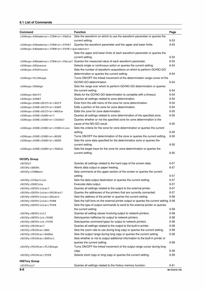
6-6 IM 701610-17E
Command Function Page
:GONogo:PARameter:ITEM<x>:TRACe Sets the waveform on which to use the waveform parameter or queries the
current setting. 6-53
:GONogo:PARameter:ITEM<x>:TYPE? Queries the waveform parameter and the upper and lower limits. 6-53
:GONogo:PARameter:ITEM<x>:TYPE:<parameter>
Sets the upper and lower limits of each waveform parameter or queries the
current setting. 6-53
:GONogo:PARameter:ITEM<x>:VALue? Queries the measured value of each waveform parameter. 6-53
:GONogo:SEQuence Selects single or continuous action or queries the current setting. 6-54
:GONogo:STOPcount Sets the number of waveform acquisitions on which to perform GO/NO-GO
determination or queries the current setting. 6-54
:GONogo:TLINkage Turns ON/OFF the linked movement of the determination range cursor of the
GO/NO-GO determination. 6-54
:GONogo:TRANge Sets the range over which to perform GO/NO-GO determination or queries
the current setting. 6-54
:GONogo:WAIT? Waits for the GO/NO-GO determination to complete with a timeout. 6-54
:GONogo:ZONE? Queries all settings related to zone determination. 6-54
:GONogo:ZONE:EDIT<x>:EXIT Exits from the edit menu of the zone for zone determination. 6-54
:GONogo:ZONE:EDIT<x>:PART Edits a portion of the zone for zone determination. 6-54
:GONogo:ZONE:EDIT<x>:WHOLe Edits the zone for zone determination. 6-55
:GONogo:ZONE:ZONE<x>? Queries all settings related to zone determination of the specified zone. 6-55
:GONogo:ZONE:ZONE<x>:CAUSe? Queries whether or not the specified zone for zone determination is the
cause of the NO-GO result. 6-55
:GONogo:ZONE:ZONE<x>:CONDition Sets the criteria for the zone for zone determination or queries the current
setting. 6-55
:GONogo:ZONE:ZONE<x>:MODE Turns ON/OFF the determination of the zone or queries the current setting. 6-55
:GONogo:ZONE:ZONE<x>:SEND Sets the zone data specified for the determination zone or queries the
current setting. 6-55
:GONogo:ZONE:ZONE<x>:TRACe Sets the target trace for the zone for zone determination or queries the
current setting. 6-55
HCOPy Group
:HCOPy? Queries all settings related to the hard copy of the screen data. 6-57
:HCOPy:ABORt Aborts data output or paper feeding. 6-57
:HCOPy:COMMent Sets comments at the upper section of the screen or queries the current
setting. 6-57
:HCOPy:DIRection Sets the data output destination or queries the current setting. 6-57
:HCOPy:EXECute Executes data output. 6-57
:HCOPy:EXTPrinter? Queries all settings related to the output to the external printer. 6-57
:HCOPy:EXTPrinter:PRINter? Queries the addresses of the printers that are currently connected. 6-57
:HCOPy:EXTPrinter:SELect Sets the address of the printer or queries the current setting. 6-58
:HCOPy:EXTPrinter:TONE Sets the half tone on the external printer output or queries the current setting. 6-58
:HCOPy:EXTPrinter:TYPE Sets the type of output commands to send to the external printer or queries
the current setting. 6-58
:HCOPy:NETPrint? Queries all setting values involving output to network printers. 6-58
:HCOPy:NETPrint:TONE Sets/queries halftones for output to network printers. 6-58
:HCOPy:NETPrint:TYPE Sets/queries command types for output to network printers. 6-58
:HCOPy:PRINter? Queries all settings related to the output to the built-in printer. 6-58
:HCOPy:PRINter:MAG Sets the zoom rate to use during long copy or queries the current setting. 6-58
:HCOPy:PRINter:RANGe Sets the output range during long copy or queries the current setting. 6-58
:HCOPy:PRINter:REPort Sets whether or not to output additional information to the built-in printer or
queries the current setting. 6-58
:HCOPy:PRINter:TLINkage Turns ON/OFF the linked movement of the output range cursor during long
copy. 6-59
:HCOPy:PRINter:TYPE Selects short copy or long copy or queries the current setting. 6-59
HISTory Group
:HISTory? Queries all settings related to the history memory function. 6-61
6.1 List of Commands
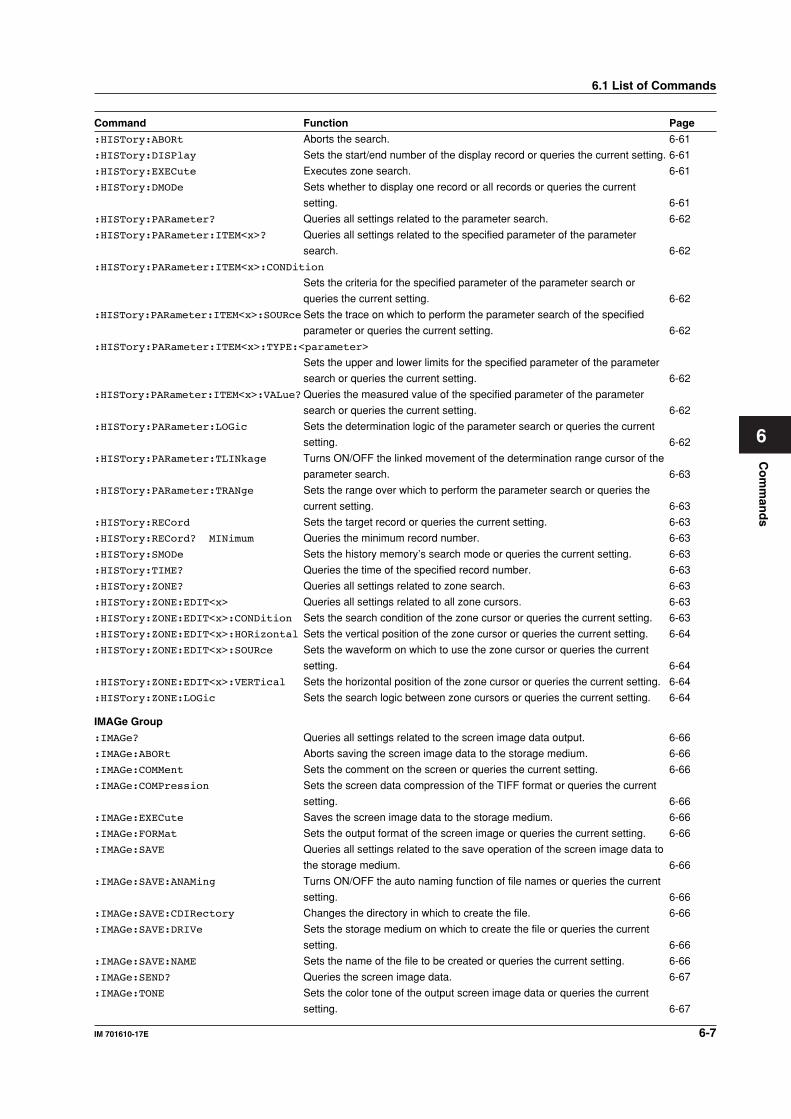
Co
mm
and
s
6-7IM 701610-17E
6
Command Function Page
:HISTory:ABORt Aborts the search. 6-61
:HISTory:DISPlay Sets the start/end number of the display record or queries the current setting. 6-61
:HISTory:EXECute Executes zone search. 6-61
:HISTory:DMODe Sets whether to display one record or all records or queries the current
setting. 6-61
:HISTory:PARameter? Queries all settings related to the parameter search. 6-62
:HISTory:PARameter:ITEM<x>? Queries all settings related to the specified parameter of the parameter
search. 6-62
:HISTory:PARameter:ITEM<x>:CONDition
Sets the criteria for the specified parameter of the parameter search or
queries the current setting. 6-62
:HISTory:PARameter:ITEM<x>:SOURceSets the trace on which to perform the parameter search of the specified
parameter or queries the current setting. 6-62
:HISTory:PARameter:ITEM<x>:TYPE:<parameter>
Sets the upper and lower limits for the specified parameter of the parameter
search or queries the current setting. 6-62
:HISTory:PARameter:ITEM<x>:VALue?Queries the measured value of the specified parameter of the parameter
search or queries the current setting. 6-62
:HISTory:PARameter:LOGic Sets the determination logic of the parameter search or queries the current
setting. 6-62
:HISTory:PARameter:TLINkage Turns ON/OFF the linked movement of the determination range cursor of the
parameter search. 6-63
:HISTory:PARameter:TRANge Sets the range over which to perform the parameter search or queries the
current setting. 6-63
:HISTory:RECord Sets the target record or queries the current setting. 6-63
:HISTory:RECord? MINimum Queries the minimum record number. 6-63
:HISTory:SMODe Sets the history memory’s search mode or queries the current setting. 6-63
:HISTory:TIME? Queries the time of the specified record number. 6-63
:HISTory:ZONE? Queries all settings related to zone search. 6-63
:HISTory:ZONE:EDIT<x> Queries all settings related to all zone cursors. 6-63
:HISTory:ZONE:EDIT<x>:CONDition Sets the search condition of the zone cursor or queries the current setting. 6-63
:HISTory:ZONE:EDIT<x>:HORizontal Sets the vertical position of the zone cursor or queries the current setting. 6-64
:HISTory:ZONE:EDIT<x>:SOURce Sets the waveform on which to use the zone cursor or queries the current
setting. 6-64
:HISTory:ZONE:EDIT<x>:VERTical Sets the horizontal position of the zone cursor or queries the current setting. 6-64
:HISTory:ZONE:LOGic Sets the search logic between zone cursors or queries the current setting. 6-64
IMAGe Group
:IMAGe? Queries all settings related to the screen image data output. 6-66
:IMAGe:ABORt Aborts saving the screen image data to the storage medium. 6-66
:IMAGe:COMMent Sets the comment on the screen or queries the current setting. 6-66
:IMAGe:COMPression Sets the screen data compression of the TIFF format or queries the current
setting. 6-66
:IMAGe:EXECute Saves the screen image data to the storage medium. 6-66
:IMAGe:FORMat Sets the output format of the screen image or queries the current setting. 6-66
:IMAGe:SAVE Queries all settings related to the save operation of the screen image data to
the storage medium. 6-66
:IMAGe:SAVE:ANAMing Turns ON/OFF the auto naming function of file names or queries the current
setting. 6-66
:IMAGe:SAVE:CDIRectory Changes the directory in which to create the file. 6-66
:IMAGe:SAVE:DRIVe Sets the storage medium on which to create the file or queries the current
setting. 6-66
:IMAGe:SAVE:NAME Sets the name of the file to be created or queries the current setting. 6-66
:IMAGe:SEND? Queries the screen image data. 6-67
:IMAGe:TONE Sets the color tone of the output screen image data or queries the current
setting. 6-67
6.1 List of Commands
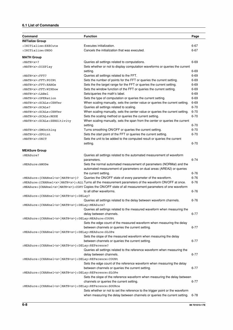
6-8 IM 701610-17E
Command Function Page
INITialize Group
:INITialize:EXECute Executes initialization. 6-67
:INITialize:UNDO Cancels the initialization that was executed. 6-67
MATH Group
:MATH<x>? Queries all settings related to computations. 6-69
:MATH<x>:DISPlay Sets whether or not to display computation waveforms or queries the currentsetting. 6-69
:MATH<x>:FFT? Queries all settings related to the FFT. 6-69:MATH<x>:FFT:POINt Sets the number of points for the FFT or queries the current setting. 6-69:MATH<x>:FFT:RANGe Sets the the target range for the FFT or queries the current setting. 6-69:MATH<x>:FFT:WINDow Sets the window function of the FFT or queries the current setting. 6-69:MATH<x>:LABel Sets/queries the math’s label. 6-69:MATH<x>:OPERation Sets the type of computation or queries the current setting. 6-69:MATH<x>:SCALe:CENTer When scaling manually, sets the center value or queries the current setting. 6-69:MATH<x>:SCALe? Queries all settings related to scaling. 6-70:MATH<x>:SCALe:CENTer When scaling manually, sets the center value or queries the current setting. 6-70:MATH<x>:SCALe:MODE Sets the scaling method or queries the current setting. 6-70:MATH<x>:SCALe:SENSitivity When scaling manually, sets the span from the center or queries the current
setting. 6-70:MATH<x>:SMOothing Turns smoothing ON/OFF or queries the current setting. 6-70:MATH<x>:SPOint Sets the start point of the FFT or queries the current setting. 6-70:MATH<x>:UNIT Sets the unit to be added to the computed result or queries the current
setting. 6-70
MEASure Group
:MEASure? Queries all settings related to the automated measurement of waveform
parameters. 6-74:MEASure:AMODe Sets the normal automated measurement of parameters (NORMal) and the
automated measurement of parameters on dual areas (AREA2) or queriesthe current setting. 6-76
:MEASure:CHANnel<x>|MATH<x>? Queries the ON/OFF state of every parameter of the waveform. 6-76:MEASure:CHANnel<x>|MATH<x>:ALL Turns all the measurement parameters of the waveform ON/OFF at once. 6-76:MEASure:CHANnel<x>|MATH<x>:COPY Copies the ON/OFF state of all measurement parameters of one waveform
to all other waveforms. 6-76:MEASure:CHANnel<x>|MATH<x>:DELay?
Queries all settings related to the delay between waveform channels. 6-76:MEASure:CHANnel<x>|MATH<x>:DELay:MEASure?
Queries all settings related to the measured waveform when measuring thedelay between channels. 6-77
:MEASure:CHANnel<x>|MATH<x>:DELay:MEASure:COUNt
Sets the edge count of the measured waveform when measuring the delaybetween channels or queries the current setting. 6-77
:MEASure:CHANnel<x>|MATH<x>:DELay:MEASure:SLOPe
Sets the slope of the measured waveform when measuring the delaybetween channels or queries the current setting. 6-77
:MEASure:CHANnel<x>|MATH<x>:DELay:REFerence?
Queries all settings related to the reference waveform when measuring thedelay between channels. 6-77
:MEASure:CHANnel<x>|MATH<x>:DELay:REFerence:COUNt
Sets the edge count of the reference waveform when measuring the delaybetween channels or queries the current setting. 6-77
:MEASure:CHANnel<x>|MATH<x>:DELay:REFerence:SLOPe
Sets the slope of the reference waveform when measuring the delay betweenchannels or queries the current setting. 6-77
:MEASure:CHANnel<x>|MATH<x>:DELay:REFerence:SOURce
Sets whether or not to set the reference to the trigger point or the waveform
when measuring the delay between channels or queries the current setting. 6-78
6.1 List of Commands
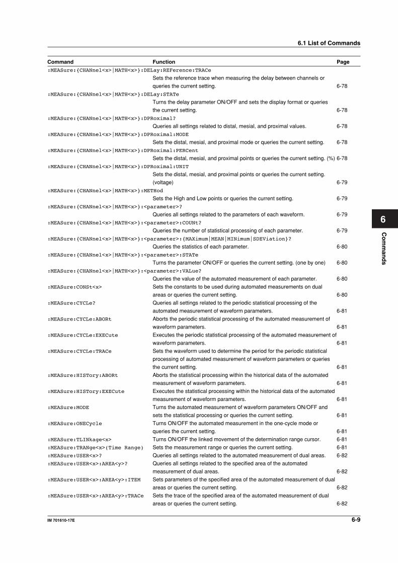
Co
mm
and
s
6-9IM 701610-17E
6
Command Function Page
:MEASure:CHANnel<x>|MATH<x>:DELay:REFerence:TRACe
Sets the reference trace when measuring the delay between channels or
queries the current setting. 6-78
:MEASure:CHANnel<x>|MATH<x>:DELay:STATe
Turns the delay parameter ON/OFF and sets the display format or queries
the current setting. 6-78
:MEASure:CHANnel<x>|MATH<x>:DPRoximal?
Queries all settings related to distal, mesial, and proximal values. 6-78
:MEASure:CHANnel<x>|MATH<x>:DPRoximal:MODE
Sets the distal, mesial, and proximal mode or queries the current setting. 6-78
:MEASure:CHANnel<x>|MATH<x>:DPRoximal:PERCent
Sets the distal, mesial, and proximal points or queries the current setting. (%) 6-78
:MEASure:CHANnel<x>|MATH<x>:DPRoximal:UNIT
Sets the distal, mesial, and proximal points or queries the current setting.
(voltage) 6-79
:MEASure:CHANnel<x>|MATH<x>:METHod
Sets the High and Low points or queries the current setting. 6-79
:MEASure:CHANnel<x>|MATH<x>:<parameter>?
Queries all settings related to the parameters of each waveform. 6-79
:MEASure:CHANnel<x>|MATH<x>:<parameter>:COUNt?
Queries the number of statistical processing of each parameter. 6-79
:MEASure:CHANnel<x>|MATH<x>:<parameter>:MAXimum|MEAN|MINimum|SDEViation?
Queries the statistics of each parameter. 6-80
:MEASure:CHANnel<x>|MATH<x>:<parameter>:STATe
Turns the parameter ON/OFF or queries the current setting. (one by one) 6-80
:MEASure:CHANnel<x>|MATH<x>:<parameter>:VALue?
Queries the value of the automated measurement of each parameter. 6-80
:MEASure:CONSt<x> Sets the constants to be used during automated measurements on dual
areas or queries the current setting. 6-80
:MEASure:CYCLe? Queries all settings related to the periodic statistical processing of the
automated measurement of waveform parameters. 6-81
:MEASure:CYCLe:ABORt Aborts the periodic statistical processing of the automated measurement of
waveform parameters. 6-81
:MEASure:CYCLe:EXECute Executes the periodic statistical processing of the automated measurement of
waveform parameters. 6-81
:MEASure:CYCLe:TRACe Sets the waveform used to determine the period for the periodic statistical
processing of automated measurement of waveform parameters or queries
the current setting. 6-81
:MEASure:HISTory:ABORt Aborts the statistical processing within the historical data of the automated
measurement of waveform parameters. 6-81
:MEASure:HISTory:EXECute Executes the statistical processing within the historical data of the automated
measurement of waveform parameters. 6-81
:MEASure:MODE Turns the automated measurement of waveform parameters ON/OFF and
sets the statistical processing or queries the current setting. 6-81
:MEASure:ONECycle Turns ON/OFF the automated measurement in the one-cycle mode or
queries the current setting. 6-81
:MEASure:TLINkage<x> Turns ON/OFF the linked movement of the determination range cursor. 6-81
:MEASure:TRANge<x>(Time Range) Sets the measurement range or queries the current setting. 6-81
:MEASure:USER<x>? Queries all settings related to the automated measurement of dual areas. 6-82
:MEASure:USER<x>:AREA<y>? Queries all settings related to the specified area of the automated
measurement of dual areas. 6-82
:MEASure:USER<x>:AREA<y>:ITEM Sets parameters of the specified area of the automated measurement of dual
areas or queries the current setting. 6-82
:MEASure:USER<x>:AREA<y>:TRACe Sets the trace of the specified area of the automated measurement of dual
areas or queries the current setting. 6-82
6.1 List of Commands
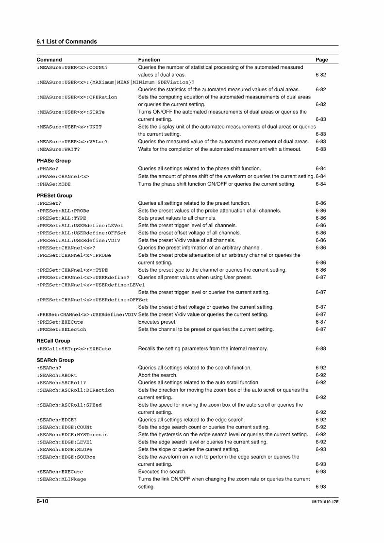
6-10 IM 701610-17E
Command Function Page:MEASure:USER<x>:COUNt? Queries the number of statistical processing of the automated measured
values of dual areas. 6-82:MEASure:USER<x>:MAXimum|MEAN|MINimum|SDEViation?
Queries the statistics of the automated measured values of dual areas. 6-82:MEASure:USER<x>:OPERation Sets the computing equation of the automated measurements of dual areas
or queries the current setting. 6-82:MEASure:USER<x>:STATe Turns ON/OFF the automated measurements of dual areas or queries the
current setting. 6-83:MEASure:USER<x>:UNIT Sets the display unit of the automated measurements of dual areas or queries
the current setting. 6-83:MEASure:USER<x>:VALue? Queries the measured value of the automated measurement of dual areas. 6-83
:MEASure:WAIT? Waits for the completion of the automated measurement with a timeout. 6-83
PHASe Group
:PHASe? Queries all settings related to the phase shift function. 6-84
:PHASe:CHANnel<x> Sets the amount of phase shift of the waveform or queries the current setting. 6-84
:PHASe:MODE Turns the phase shift function ON/OFF or queries the current setting. 6-84
PRESet Group:PRESet? Queries all settings related to the preset function. 6-86:PRESet:ALL:PROBe Sets the preset values of the probe attenuation of all channels. 6-86:PRESet:ALL:TYPE Sets preset values to all channels. 6-86:PRESet:ALL:USERdefine:LEVel Sets the preset trigger level of all channels. 6-86:PRESet:ALL:USERdefine:OFFSet Sets the preset offset voltage of all channels. 6-86:PRESet:ALL:USERdefine:VDIV Sets the preset V/div value of all channels. 6-86:PRESet:CHANnel<x>? Queries the preset information of an arbitrary channel. 6-86:PRESet:CHANnel<x>:PROBe Sets the preset probe attenuation of an arbitrary channel or queries the
current setting. 6-86:PRESet:CHANnel<x>:TYPE Sets the preset type to the channel or queries the current setting. 6-86:PRESet:CHANnel<x>:USERdefine? Queries all preset values when using User preset. 6-87:PRESet:CHANnel<x>:USERdefine:LEVel
Sets the preset trigger level or queries the current setting. 6-87:PRESet:CHANnel<x>:USERdefine:OFFSet
Sets the preset offset voltage or queries the current setting. 6-87:PRESet:CHANnel<x>:USERdefine:VDIV Sets the preset V/div value or queries the current setting. 6-87:PRESet:EXECute Executes preset. 6-87:PRESet:SELectch Sets the channel to be preset or queries the current setting. 6-87
RECall Group
:RECall:SETup<x>:EXECute Recalls the setting parameters from the internal memory. 6-88
SEARch Group:SEARch? Queries all settings related to the search function. 6-92:SEARch:ABORt Abort the search. 6-92:SEARch:ASCRoll? Queries all settings related to the auto scroll function. 6-92:SEARch:ASCRoll:DIRection Sets the direction for moving the zoom box of the auto scroll or queries the
current setting. 6-92:SEARch:ASCRoll:SPEed Sets the speed for moving the zoom box of the auto scroll or queries the
current setting. 6-92:SEARch:EDGE? Queries all settings related to the edge search. 6-92:SEARch:EDGE:COUNt Sets the edge search count or queries the current setting. 6-92:SEARch:EDGE:HYSTeresis Sets the hysteresis on the edge search level or queries the current setting. 6-92:SEARch:EDGE:LEVEl Sets the edge search level or queries the current setting. 6-92:SEARch:EDGE:SLOPe Sets the slope or queries the current setting. 6-93:SEARch:EDGE:SOURce Sets the waveform on which to perform the edge search or queries the
current setting. 6-93:SEARch:EXECute Executes the search. 6-93:SEARch:MLINkage Turns the link ON/OFF when changing the zoom rate or queries the current
setting. 6-93
6.1 List of Commands
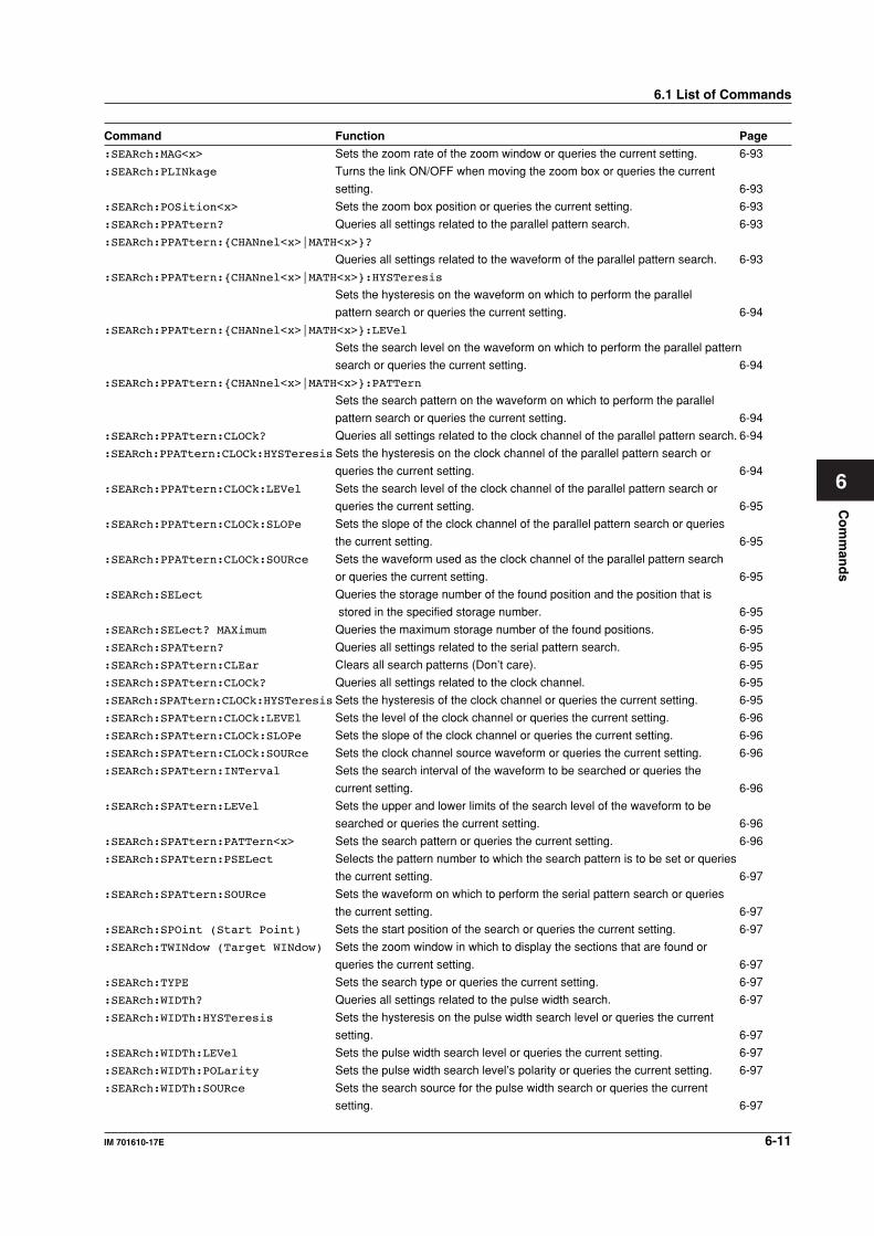
Co
mm
and
s
6-11IM 701610-17E
6
Command Function Page
:SEARch:MAG<x> Sets the zoom rate of the zoom window or queries the current setting. 6-93
:SEARch:PLINkage Turns the link ON/OFF when moving the zoom box or queries the current
setting. 6-93
:SEARch:POSition<x> Sets the zoom box position or queries the current setting. 6-93
:SEARch:PPATtern? Queries all settings related to the parallel pattern search. 6-93
:SEARch:PPATtern:CHANnel<x>|MATH<x>?
Queries all settings related to the waveform of the parallel pattern search. 6-93
:SEARch:PPATtern:CHANnel<x>|MATH<x>:HYSTeresis
Sets the hysteresis on the waveform on which to perform the parallel
pattern search or queries the current setting. 6-94
:SEARch:PPATtern:CHANnel<x>|MATH<x>:LEVel
Sets the search level on the waveform on which to perform the parallel pattern
search or queries the current setting. 6-94
:SEARch:PPATtern:CHANnel<x>|MATH<x>:PATTern
Sets the search pattern on the waveform on which to perform the parallel
pattern search or queries the current setting. 6-94
:SEARch:PPATtern:CLOCk? Queries all settings related to the clock channel of the parallel pattern search. 6-94
:SEARch:PPATtern:CLOCk:HYSTeresisSets the hysteresis on the clock channel of the parallel pattern search or
queries the current setting. 6-94
:SEARch:PPATtern:CLOCk:LEVel Sets the search level of the clock channel of the parallel pattern search or
queries the current setting. 6-95
:SEARch:PPATtern:CLOCk:SLOPe Sets the slope of the clock channel of the parallel pattern search or queries
the current setting. 6-95
:SEARch:PPATtern:CLOCk:SOURce Sets the waveform used as the clock channel of the parallel pattern search
or queries the current setting. 6-95
:SEARch:SELect Queries the storage number of the found position and the position that is
stored in the specified storage number. 6-95
:SEARch:SELect? MAXimum Queries the maximum storage number of the found positions. 6-95
:SEARch:SPATtern? Queries all settings related to the serial pattern search. 6-95
:SEARch:SPATtern:CLEar Clears all search patterns (Don’t care). 6-95
:SEARch:SPATtern:CLOCk? Queries all settings related to the clock channel. 6-95
:SEARch:SPATtern:CLOCk:HYSTeresisSets the hysteresis of the clock channel or queries the current setting. 6-95
:SEARch:SPATtern:CLOCk:LEVEl Sets the level of the clock channel or queries the current setting. 6-96
:SEARch:SPATtern:CLOCk:SLOPe Sets the slope of the clock channel or queries the current setting. 6-96
:SEARch:SPATtern:CLOCk:SOURce Sets the clock channel source waveform or queries the current setting. 6-96
:SEARch:SPATtern:INTerval Sets the search interval of the waveform to be searched or queries the
current setting. 6-96
:SEARch:SPATtern:LEVel Sets the upper and lower limits of the search level of the waveform to be
searched or queries the current setting. 6-96
:SEARch:SPATtern:PATTern<x> Sets the search pattern or queries the current setting. 6-96
:SEARch:SPATtern:PSELect Selects the pattern number to which the search pattern is to be set or queries
the current setting. 6-97
:SEARch:SPATtern:SOURce Sets the waveform on which to perform the serial pattern search or queries
the current setting. 6-97
:SEARch:SPOint (Start Point) Sets the start position of the search or queries the current setting. 6-97
:SEARch:TWINdow (Target WINdow) Sets the zoom window in which to display the sections that are found or
queries the current setting. 6-97
:SEARch:TYPE Sets the search type or queries the current setting. 6-97
:SEARch:WIDTh? Queries all settings related to the pulse width search. 6-97
:SEARch:WIDTh:HYSTeresis Sets the hysteresis on the pulse width search level or queries the current
setting. 6-97
:SEARch:WIDTh:LEVel Sets the pulse width search level or queries the current setting. 6-97
:SEARch:WIDTh:POLarity Sets the pulse width search level’s polarity or queries the current setting. 6-97
:SEARch:WIDTh:SOURce Sets the search source for the pulse width search or queries the current
setting. 6-97
6.1 List of Commands
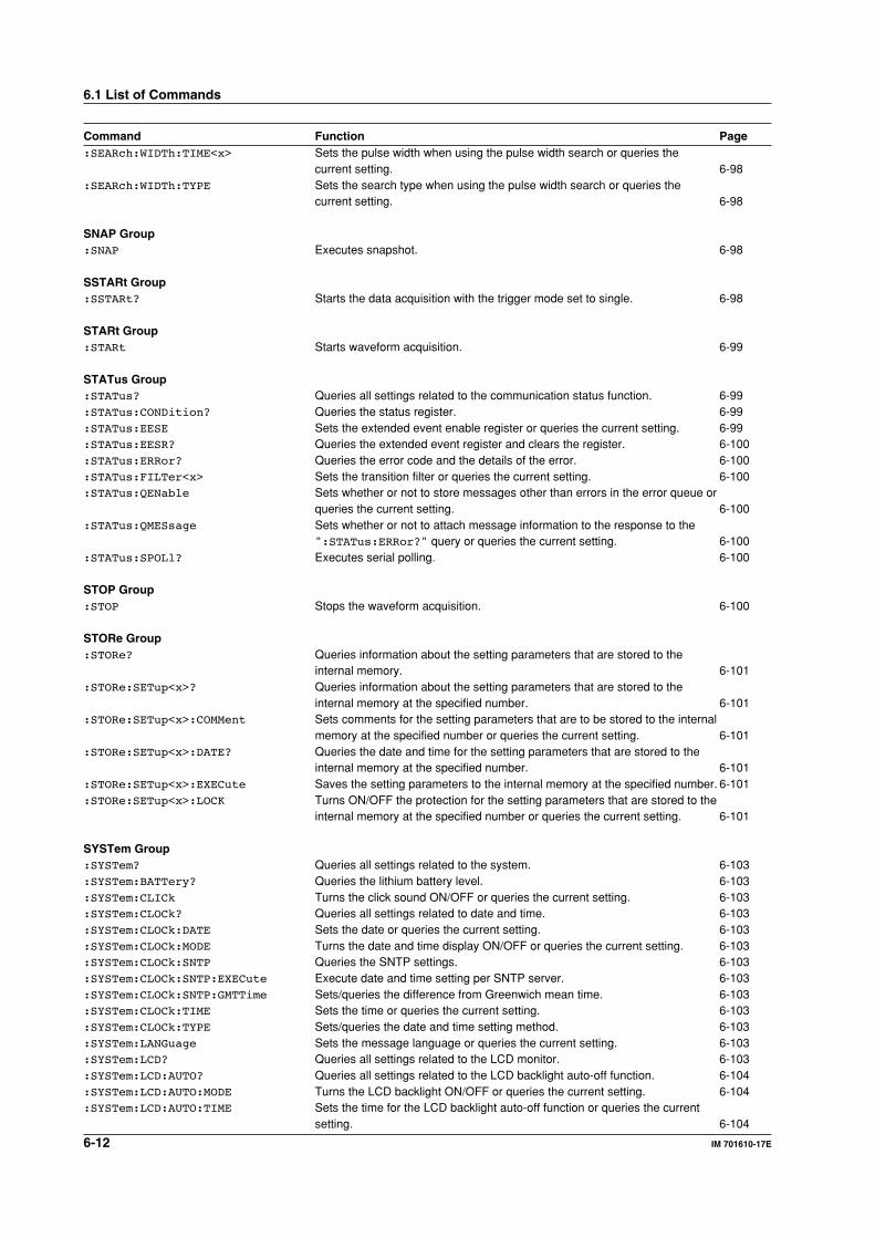
6-12 IM 701610-17E
Command Function Page:SEARch:WIDTh:TIME<x> Sets the pulse width when using the pulse width search or queries the
current setting. 6-98:SEARch:WIDTh:TYPE Sets the search type when using the pulse width search or queries the
current setting. 6-98
SNAP Group:SNAP Executes snapshot. 6-98
SSTARt Group:SSTARt? Starts the data acquisition with the trigger mode set to single. 6-98
STARt Group:STARt Starts waveform acquisition. 6-99
STATus Group:STATus? Queries all settings related to the communication status function. 6-99:STATus:CONDition? Queries the status register. 6-99:STATus:EESE Sets the extended event enable register or queries the current setting. 6-99:STATus:EESR? Queries the extended event register and clears the register. 6-100:STATus:ERRor? Queries the error code and the details of the error. 6-100:STATus:FILTer<x> Sets the transition filter or queries the current setting. 6-100:STATus:QENable Sets whether or not to store messages other than errors in the error queue or
queries the current setting. 6-100:STATus:QMESsage Sets whether or not to attach message information to the response to the
":STATus:ERRor?" query or queries the current setting. 6-100:STATus:SPOLl? Executes serial polling. 6-100
STOP Group:STOP Stops the waveform acquisition. 6-100
STORe Group:STORe? Queries information about the setting parameters that are stored to the
internal memory. 6-101:STORe:SETup<x>? Queries information about the setting parameters that are stored to the
internal memory at the specified number. 6-101:STORe:SETup<x>:COMMent Sets comments for the setting parameters that are to be stored to the internal
memory at the specified number or queries the current setting. 6-101:STORe:SETup<x>:DATE? Queries the date and time for the setting parameters that are stored to the
internal memory at the specified number. 6-101:STORe:SETup<x>:EXECute Saves the setting parameters to the internal memory at the specified number. 6-101:STORe:SETup<x>:LOCK Turns ON/OFF the protection for the setting parameters that are stored to the
internal memory at the specified number or queries the current setting. 6-101
SYSTem Group:SYSTem? Queries all settings related to the system. 6-103:SYSTem:BATTery? Queries the lithium battery level. 6-103:SYSTem:CLICk Turns the click sound ON/OFF or queries the current setting. 6-103:SYSTem:CLOCk? Queries all settings related to date and time. 6-103:SYSTem:CLOCk:DATE Sets the date or queries the current setting. 6-103:SYSTem:CLOCk:MODE Turns the date and time display ON/OFF or queries the current setting. 6-103:SYSTem:CLOCk:SNTP Queries the SNTP settings. 6-103:SYSTem:CLOCk:SNTP:EXECute Execute date and time setting per SNTP server. 6-103:SYSTem:CLOCk:SNTP:GMTTime Sets/queries the difference from Greenwich mean time. 6-103:SYSTem:CLOCk:TIME Sets the time or queries the current setting. 6-103:SYSTem:CLOCk:TYPE Sets/queries the date and time setting method. 6-103:SYSTem:LANGuage Sets the message language or queries the current setting. 6-103:SYSTem:LCD? Queries all settings related to the LCD monitor. 6-103:SYSTem:LCD:AUTO? Queries all settings related to the LCD backlight auto-off function. 6-104:SYSTem:LCD:AUTO:MODE Turns the LCD backlight ON/OFF or queries the current setting. 6-104:SYSTem:LCD:AUTO:TIME Sets the time for the LCD backlight auto-off function or queries the current
setting. 6-104
6.1 List of Commands
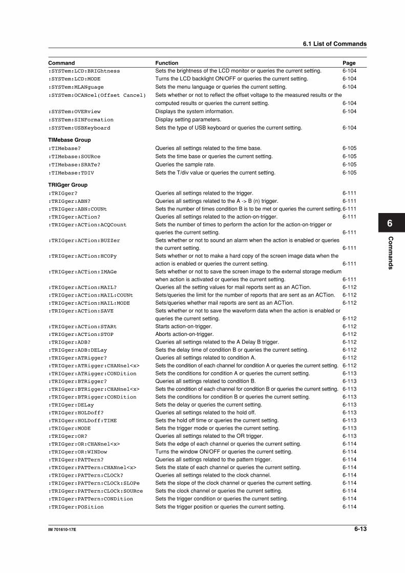
Co
mm
and
s
6-13IM 701610-17E
6
6.1 List of Commands
Command Function Page:SYSTem:LCD:BRIGhtness Sets the brightness of the LCD monitor or queries the current setting. 6-104
:SYSTem:LCD:MODE Turns the LCD backlight ON/OFF or queries the current setting. 6-104
:SYSTem:MLANguage Sets the menu language or queries the current setting. 6-104
:SYSTem:OCANcel(Offset Cancel) Sets whether or not to reflect the offset voltage to the measured results or the
computed results or queries the current setting. 6-104
:SYSTem:OVERview Displays the system information. 6-104
:SYSTem:SINFormation Display setting parameters.
:SYSTem:USBKeyboard Sets the type of USB keyboard or queries the current setting. 6-104
TIMebase Group
:TIMebase? Queries all settings related to the time base. 6-105
:TIMebase:SOURce Sets the time base or queries the current setting. 6-105
:TIMebase:SRATe? Queries the sample rate. 6-105
:TIMebase:TDIV Sets the T/div value or queries the current setting. 6-105
TRIGger Group
:TRIGger? Queries all settings related to the trigger. 6-111
:TRIGger:ABN? Queries all settings related to the A -> B (n) trigger. 6-111:TRIGger:ABN:COUNt Sets the number of times condition B is to be met or queries the current setting.6-111:TRIGger:ACTion? Queries all settings related to the action-on-trigger. 6-111:TRIGger:ACTion:ACQCount Sets the number of times to perform the action for the action-on-trigger or
queries the current setting. 6-111:TRIGger:ACTion:BUZZer Sets whether or not to sound an alarm when the action is enabled or queries
the current setting. 6-111:TRIGger:ACTion:HCOPy Sets whether or not to make a hard copy of the screen image data when the
action is enabled or queries the current setting. 6-111:TRIGger:ACTion:IMAGe Sets whether or not to save the screen image to the external storage medium
when action is activated or queries the current setting. 6-111:TRIGger:ACTion:MAIL? Queries all the setting values for mail reports sent as an ACTion. 6-112:TRIGger:ACTion:MAIL:COUNt Sets/queries the limit for the number of reports that are sent as an ACTion. 6-112:TRIGger:ACTion:MAIL:MODE Sets/queries whether mail reports are sent as an ACTion. 6-112:TRIGger:ACTion:SAVE Sets whether or not to save the waveform data when the action is enabled or
queries the current setting. 6-112:TRIGger:ACTion:STARt Starts action-on-trigger. 6-112:TRIGger:ACTion:STOP Aborts action-on-trigger. 6-112:TRIGger:ADB? Queries all settings related to the A Delay B trigger. 6-112:TRIGger:ADB:DELay Sets the delay time of condition B or queries the current setting. 6-112:TRIGger:ATRigger? Queries all settings related to condition A. 6-112:TRIGger:ATRigger:CHANnel<x> Sets the condition of each channel for condition A or queries the current setting. 6-112:TRIGger:ATRigger:CONDition Sets the conditions for condition A or queries the current setting. 6-113:TRIGger:BTRigger? Queries all settings related to condition B. 6-113:TRIGger:BTRigger:CHANnel<x> Sets the condition of each channel for condition B or queries the current setting. 6-113:TRIGger:BTRigger:CONDition Sets the conditions for condition B or queries the current setting. 6-113:TRIGger:DELay Sets the delay or queries the current setting. 6-113:TRIGger:HOLDoff? Queries all settings related to the hold off. 6-113:TRIGger:HOLDoff:TIME Sets the hold off time or queries the current setting. 6-113:TRIGger:MODE Sets the trigger mode or queries the current setting. 6-113:TRIGger:OR? Queries all settings related to the OR trigger. 6-113:TRIGger:OR:CHANnel<x> Sets the edge of each channel or queries the current setting. 6-114:TRIGger:OR:WINDow Turns the window ON/OFF or queries the current setting. 6-114:TRIGger:PATTern? Queries all settings related to the pattern trigger. 6-114:TRIGger:PATTern:CHANnel<x> Sets the state of each channel or queries the current setting. 6-114:TRIGger:PATTern:CLOCk? Queries all settings related to the clock channel. 6-114:TRIGger:PATTern:CLOCk:SLOPe Sets the slope of the clock channel or queries the current setting. 6-114:TRIGger:PATTern:CLOCk:SOURce Sets the clock channel or queries the current setting. 6-114:TRIGger:PATTern:CONDition Sets the trigger condition or queries the current setting. 6-114
:TRIGger:POSition Sets the trigger position or queries the current setting. 6-114
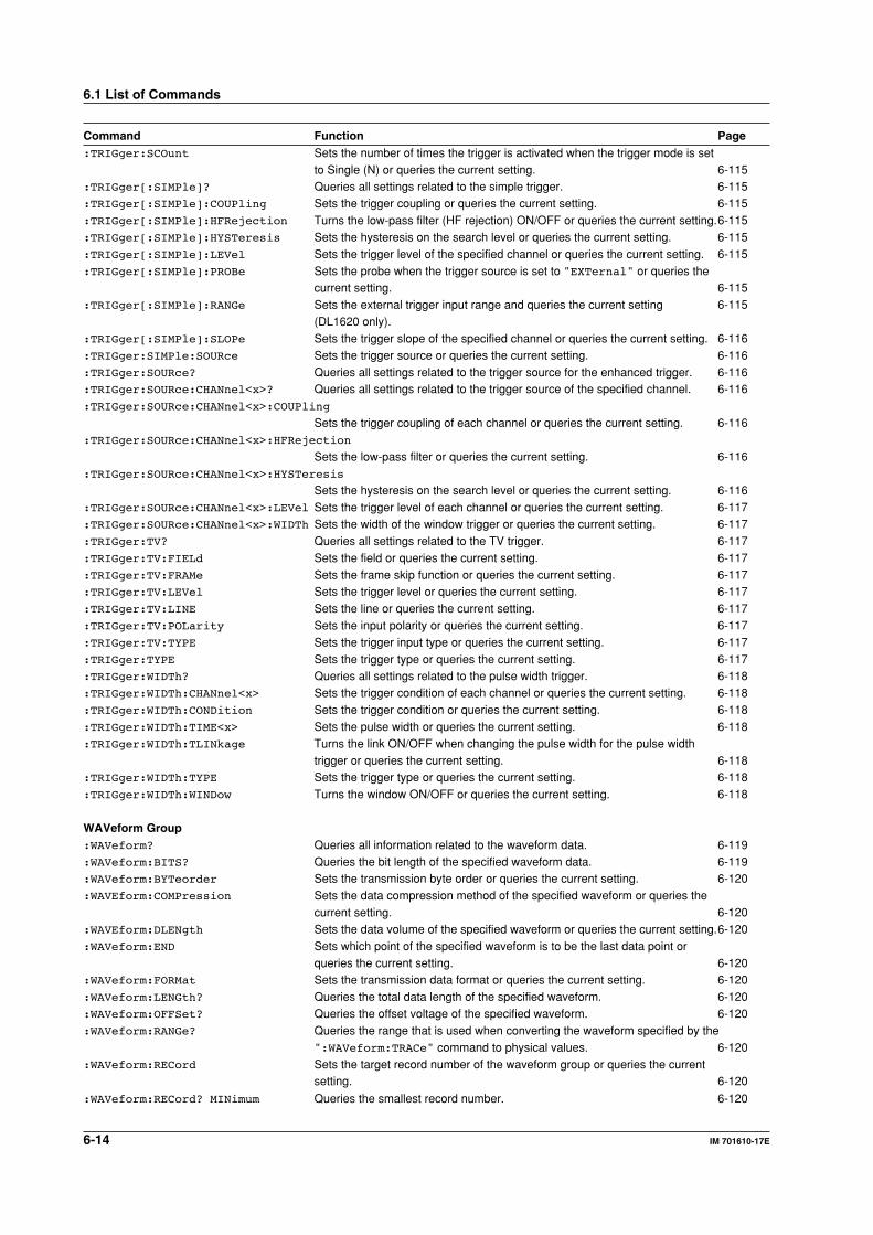
6-14 IM 701610-17E
6.1 List of Commands
Command Function Page:TRIGger:SCOunt Sets the number of times the trigger is activated when the trigger mode is set
to Single (N) or queries the current setting. 6-115:TRIGger[:SIMPle]? Queries all settings related to the simple trigger. 6-115:TRIGger[:SIMPle]:COUPling Sets the trigger coupling or queries the current setting. 6-115:TRIGger[:SIMPle]:HFRejection Turns the low-pass filter (HF rejection) ON/OFF or queries the current setting.6-115:TRIGger[:SIMPle]:HYSTeresis Sets the hysteresis on the search level or queries the current setting. 6-115:TRIGger[:SIMPle]:LEVel Sets the trigger level of the specified channel or queries the current setting. 6-115:TRIGger[:SIMPle]:PROBe Sets the probe when the trigger source is set to "EXTernal" or queries the
current setting. 6-115:TRIGger[:SIMPle]:RANGe Sets the external trigger input range and queries the current setting 6-115
(DL1620 only).:TRIGger[:SIMPle]:SLOPe Sets the trigger slope of the specified channel or queries the current setting. 6-116:TRIGger:SIMPle:SOURce Sets the trigger source or queries the current setting. 6-116:TRIGger:SOURce? Queries all settings related to the trigger source for the enhanced trigger. 6-116:TRIGger:SOURce:CHANnel<x>? Queries all settings related to the trigger source of the specified channel. 6-116:TRIGger:SOURce:CHANnel<x>:COUPling
Sets the trigger coupling of each channel or queries the current setting. 6-116:TRIGger:SOURce:CHANnel<x>:HFRejection
Sets the low-pass filter or queries the current setting. 6-116:TRIGger:SOURce:CHANnel<x>:HYSTeresis
Sets the hysteresis on the search level or queries the current setting. 6-116:TRIGger:SOURce:CHANnel<x>:LEVel Sets the trigger level of each channel or queries the current setting. 6-117:TRIGger:SOURce:CHANnel<x>:WIDTh Sets the width of the window trigger or queries the current setting. 6-117:TRIGger:TV? Queries all settings related to the TV trigger. 6-117:TRIGger:TV:FIELd Sets the field or queries the current setting. 6-117:TRIGger:TV:FRAMe Sets the frame skip function or queries the current setting. 6-117:TRIGger:TV:LEVel Sets the trigger level or queries the current setting. 6-117:TRIGger:TV:LINE Sets the line or queries the current setting. 6-117:TRIGger:TV:POLarity Sets the input polarity or queries the current setting. 6-117:TRIGger:TV:TYPE Sets the trigger input type or queries the current setting. 6-117:TRIGger:TYPE Sets the trigger type or queries the current setting. 6-117:TRIGger:WIDTh? Queries all settings related to the pulse width trigger. 6-118:TRIGger:WIDTh:CHANnel<x> Sets the trigger condition of each channel or queries the current setting. 6-118:TRIGger:WIDTh:CONDition Sets the trigger condition or queries the current setting. 6-118:TRIGger:WIDTh:TIME<x> Sets the pulse width or queries the current setting. 6-118:TRIGger:WIDTh:TLINkage Turns the link ON/OFF when changing the pulse width for the pulse width
trigger or queries the current setting. 6-118:TRIGger:WIDTh:TYPE Sets the trigger type or queries the current setting. 6-118:TRIGger:WIDTh:WINDow Turns the window ON/OFF or queries the current setting. 6-118
WAVeform Group:WAVeform? Queries all information related to the waveform data. 6-119:WAVeform:BITS? Queries the bit length of the specified waveform data. 6-119:WAVeform:BYTeorder Sets the transmission byte order or queries the current setting. 6-120:WAVEform:COMPression Sets the data compression method of the specified waveform or queries the
current setting. 6-120:WAVEform:DLENgth Sets the data volume of the specified waveform or queries the current setting.6-120:WAVeform:END Sets which point of the specified waveform is to be the last data point or
queries the current setting. 6-120:WAVeform:FORMat Sets the transmission data format or queries the current setting. 6-120:WAVeform:LENGth? Queries the total data length of the specified waveform. 6-120:WAVeform:OFFSet? Queries the offset voltage of the specified waveform. 6-120:WAVeform:RANGe? Queries the range that is used when converting the waveform specified by the
":WAVeform:TRACe" command to physical values. 6-120:WAVeform:RECord Sets the target record number of the waveform group or queries the current
setting. 6-120
:WAVeform:RECord? MINimum Queries the smallest record number. 6-120
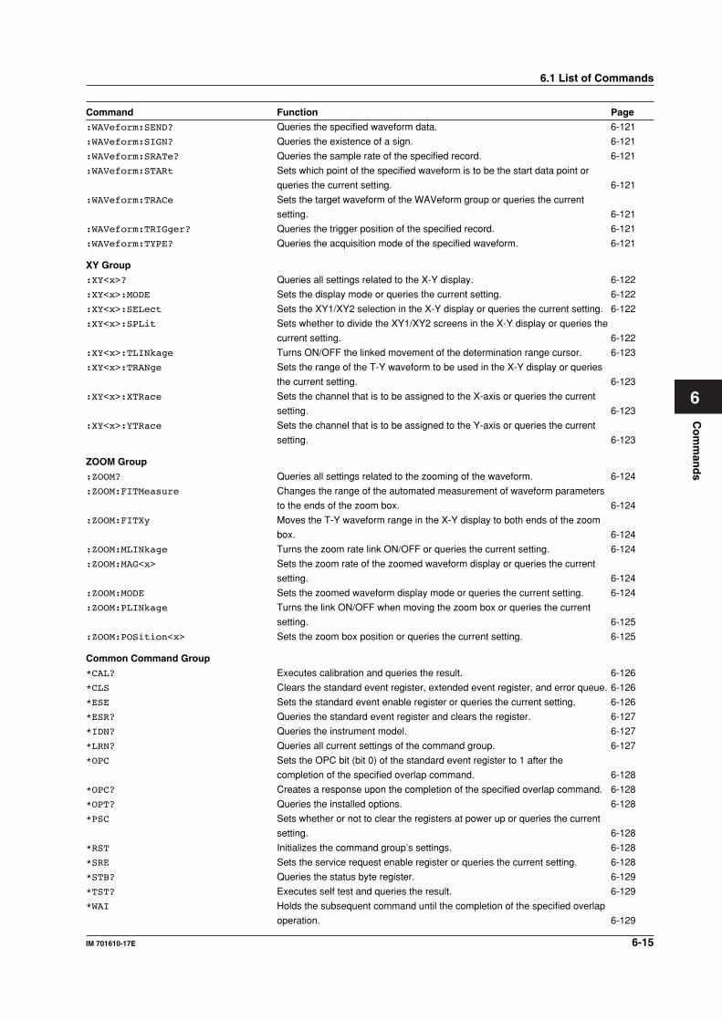
Co
mm
and
s
6-15IM 701610-17E
6
6.1 List of Commands
Command Function Page
:WAVeform:SEND? Queries the specified waveform data. 6-121
:WAVeform:SIGN? Queries the existence of a sign. 6-121
:WAVeform:SRATe? Queries the sample rate of the specified record. 6-121
:WAVeform:STARt Sets which point of the specified waveform is to be the start data point or
queries the current setting. 6-121
:WAVeform:TRACe Sets the target waveform of the WAVeform group or queries the current
setting. 6-121
:WAVeform:TRIGger? Queries the trigger position of the specified record. 6-121
:WAVeform:TYPE? Queries the acquisition mode of the specified waveform. 6-121
XY Group
:XY<x>? Queries all settings related to the X-Y display. 6-122
:XY<x>:MODE Sets the display mode or queries the current setting. 6-122
:XY<x>:SELect Sets the XY1/XY2 selection in the X-Y display or queries the current setting. 6-122
:XY<x>:SPLit Sets whether to divide the XY1/XY2 screens in the X-Y display or queries the
current setting. 6-122
:XY<x>:TLINkage Turns ON/OFF the linked movement of the determination range cursor. 6-123
:XY<x>:TRANge Sets the range of the T-Y waveform to be used in the X-Y display or queries
the current setting. 6-123
:XY<x>:XTRace Sets the channel that is to be assigned to the X-axis or queries the current
setting. 6-123
:XY<x>:YTRace Sets the channel that is to be assigned to the Y-axis or queries the current
setting. 6-123
ZOOM Group
:ZOOM? Queries all settings related to the zooming of the waveform. 6-124
:ZOOM:FITMeasure Changes the range of the automated measurement of waveform parameters
to the ends of the zoom box. 6-124
:ZOOM:FITXy Moves the T-Y waveform range in the X-Y display to both ends of the zoom
box. 6-124
:ZOOM:MLINkage Turns the zoom rate link ON/OFF or queries the current setting. 6-124
:ZOOM:MAG<x> Sets the zoom rate of the zoomed waveform display or queries the current
setting. 6-124
:ZOOM:MODE Sets the zoomed waveform display mode or queries the current setting. 6-124
:ZOOM:PLINkage Turns the link ON/OFF when moving the zoom box or queries the current
setting. 6-125
:ZOOM:POSition<x> Sets the zoom box position or queries the current setting. 6-125
Common Command Group
*CAL? Executes calibration and queries the result. 6-126
*CLS Clears the standard event register, extended event register, and error queue. 6-126
*ESE Sets the standard event enable register or queries the current setting. 6-126
*ESR? Queries the standard event register and clears the register. 6-127
*IDN? Queries the instrument model. 6-127
*LRN? Queries all current settings of the command group. 6-127
*OPC Sets the OPC bit (bit 0) of the standard event register to 1 after the
completion of the specified overlap command. 6-128
*OPC? Creates a response upon the completion of the specified overlap command. 6-128
*OPT? Queries the installed options. 6-128
*PSC Sets whether or not to clear the registers at power up or queries the current
setting. 6-128
*RST Initializes the command group’s settings. 6-128
*SRE Sets the service request enable register or queries the current setting. 6-128
*STB? Queries the status byte register. 6-129
*TST? Executes self test and queries the result. 6-129
*WAI Holds the subsequent command until the completion of the specified overlap
operation. 6-129
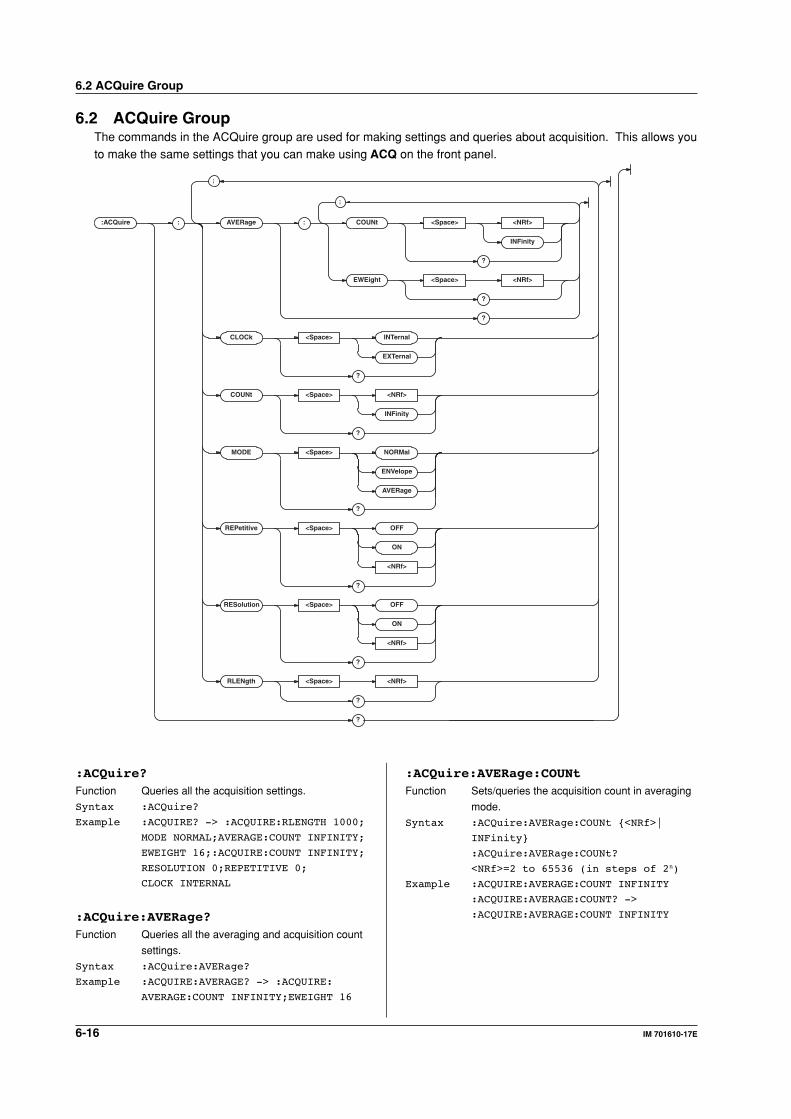
6-16 IM 701610-17E
6.2 ACQuire GroupThe commands in the ACQuire group are used for making settings and queries about acquisition. This allows youto make the same settings that you can make using ACQ on the front panel.
:ACQuire : AVERage : COUNt <Space> <NRf>
INFinity
?
EWEight <Space> <NRf>
?
?
CLOCk <Space> INTernal
EXTernal
?
COUNt <Space> <NRf>
INFinity
?
RESolution <Space> OFF
ON
<NRf>
?
MODE <Space> NORMal
ENVelope
AVERage
?
REPetitive <Space> OFF
ON
<NRf>
?
RLENgth <Space> <NRf>
?
?
;
;
:ACQuire?Function Queries all the acquisition settings.
Syntax :ACQuire?
Example :ACQUIRE? -> :ACQUIRE:RLENGTH 1000;
MODE NORMAL;AVERAGE:COUNT INFINITY;
EWEIGHT 16;:ACQUIRE:COUNT INFINITY;
RESOLUTION 0;REPETITIVE 0;
CLOCK INTERNAL
:ACQuire:AVERage?Function Queries all the averaging and acquisition count
settings.
Syntax :ACQuire:AVERage?
Example :ACQUIRE:AVERAGE? -> :ACQUIRE:
AVERAGE:COUNT INFINITY;EWEIGHT 16
6.2 ACQuire Group
:ACQuire:AVERage:COUNtFunction Sets/queries the acquisition count in averaging
mode.
Syntax :ACQuire:AVERage:COUNt <NRf>|
INFinity
:ACQuire:AVERage:COUNt?
<NRf>=2 to 65536 (in steps of 2n)
Example :ACQUIRE:AVERAGE:COUNT INFINITY
:ACQUIRE:AVERAGE:COUNT? ->
:ACQUIRE:AVERAGE:COUNT INFINITY
6-17IM 701610-17E
Co
mm
and
s
6
:ACQuire:AVERage:EWEight
(Exponent WEIGHT)Function Sets/queries the average weight for infinite
averaging mode.
Syntax :ACQuire:AVERage:EWEight <NRf>
:ACQuire:AVERage:EWEight?
<NRf>=2 to 256 (in steps of 2n)
Example :ACQUIRE:AVERAGE:EWEIGHT 16
:ACQUIRE:AVERAGE:EWEIGHT? ->
:ACQUIRE:AVERAGE:EWEIGHT 16
:ACQuire:CLOCkFunction Sets/queries the time base.
Syntax :ACQuire:CLOCk INTernal|EXTernal
:ACQuire:CLOCk?
Example :ACQUIRE:CLOCK INTERNAL
:ACQUIRE:CLOCK? -> :ACQUIRE:
CLOCK INTERNAL
:ACQuire:COUNtFunction Sets the number of waveform acquisitions
during normal mode, envelope mode, and
average mode or queries the current setting.
Syntax :ACQuire:COUNt <NRf>|INFinity
:ACQuire:COUNt?
<NRf>=2 to 65536
Example :ACQUIRE:COUNT INFINITY
:ACQUIRE:COUNT? -> :ACQUIRE:
COUNT INFINITY
:ACQuire:MODEFunction Sets/queries the waveform acquisition mode.
Syntax :ACQuire:MODE AVERage|ENVelope|
NORMal
:ACQuire:MODE?
Example :ACQUIRE:MODE NORMAL
:ACQUIRE:MODE? -> :ACQUIRE:
MODE NORMAL
6.2 ACQuire Group/6.3 ASETup Group
:ACQuire:REPetitiveFunction Turns the repetitive sampling mode ON/OFF or
queries the current setting.
Syntax :ACQuire:REPetitive <Boolean>
:ACQuire:REPetitive?
Example :ACQUIRE:REPETITIVE OFF
:ACQUIRE:REPETITIVE? -> :ACQUIRE:
REPETITIVE 0
:ACQuire:RESolutionFunction Turns the high-resolution mode ON/OFF or
queries the current setting.
Syntax :ACQuire:RESolution <Boolean>
:ACQuire:RESolution?
Example :ACQUIRE:RESOLUTION ON
:ACQUIRE:RESOLUTION?->
:ACQUIRE:RESOLUTION 1
Description When the high resolution mode is on, the
maximum record length is reduced by half.
(DL1620/DL1640, 8 M --> 4 M; DL1640L, 32 M
--> 16 M.)
:ACQuire:RLENgthFunction Sets/queries the record length.
Syntax :ACQuire:RLENgth <NRf>
:ACQuire:RLENgth?
<NRf>=1000 to 32000000 (DL1620/
DL1640L)
1000 to 8000000 (DL1640)
Example :ACQUIRE:RLENGTH 1000
:ACQUIRE:RLENGTH? -> :ACQUIRE:
RLENGTH 1000
:ASETup:EXECuteFunction Executes auto-setup.
Syntax :ASETup:EXECute
Example :ASETUP:EXECUTE
6.3 ASETup GroupThe commands in the ASETup group are used for setting and querying auto-setup. This allows you to make the
same settings and queries that you can make using the Auto Setup menu of SETUP on the front panel.:ASETup : EXECute
UNDO
:ASETup:UNDOFunction Cancels auto setup settings.
Syntax :ASETup:UNDO
Example :ASETUP:UNDO
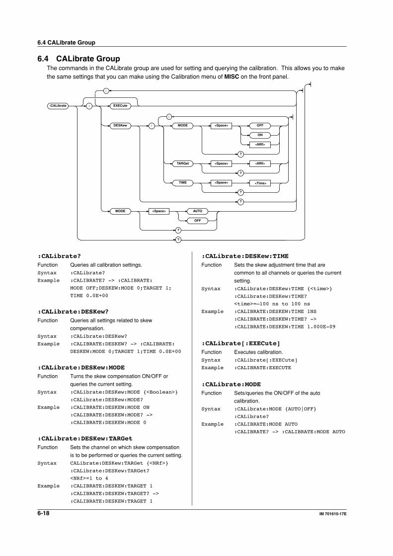
6-18 IM 701610-17E
6.4 CALibrate GroupThe commands in the CALibrate group are used for setting and querying the calibration. This allows you to makethe same settings that you can make using the Calibration menu of MISC on the front panel.
:CALibrate : EXECute
DESKew : MODE <Space> OFF
ON
<NRf>
?
TARGet <Space> <NRf>
?
TIME <Space>
?
?
MODE <Space> AUTO
OFF
?
?
;
;
<Time>
6.4 CALibrate Group
:CALibrate?Function Queries all calibration settings.
Syntax :CALibrate?
Example :CALIBRATE? -> :CALIBRATE:
MODE OFF;DESKEW:MODE 0;TARGET 1;
TIME 0.0E+00
:CALibrate:DESKew?Function Queries all settings related to skew
compensation.
Syntax :CALibrate:DESKew?
Example :CALIBRATE:DESKEW? -> :CALIBRATE:
DESKEW:MODE 0;TARGET 1;TIME 0.0E+00
:CALibrate:DESKew:MODEFunction Turns the skew compensation ON/OFF or
queries the current setting.
Syntax :CALibrate:DESKew:MODE <Boolean>
:CALibrate:DESKew:MODE?
Example :CALIBRATE:DESKEW:MODE ON
:CALIBRATE:DESKEW:MODE? ->
:CALIBRATE:DESKEW:MODE 0
:CALibrate:DESKew:TARGetFunction Sets the channel on which skew compensation
is to be performed or queries the current setting.
Syntax CALibrate:DESKew:TARGet <NRf>
:CALibrate:DESKew:TARGet?
<NRf>=1 to 4
Example :CALIBRATE:DESKEW:TARGET 1
:CALIBRATE:DESKEW:TARGET? ->
:CALIBRATE:DESKEW:TRAGET 1
:CALibrate:DESKew:TIMEFunction Sets the skew adjustment time that are
common to all channels or queries the current
setting.
Syntax :CALibrate:DESKew:TIME <time>
:CALibrate:DESKew:TIME?
<time>=–100 ns to 100 ns
Example :CALIBRATE:DESKEW:TIME 1NS
:CALIBRATE:DESKEW:TIME? ->
:CALIBRATE:DESKEW:TIME 1.000E-09
:CALibrate[:EXECute]Function Executes calibration.
Syntax :CALibrate[:EXECute]
Example :CALIBRATE:EXECUTE
:CALibrate:MODEFunction Sets/queries the ON/OFF of the auto
calibration.
Syntax :CALibrate:MODE AUTO|OFF
:CALibrate?
Example :CALIBRATE:MODE AUTO
:CALIBRATE? -> :CALIBRATE:MODE AUTO
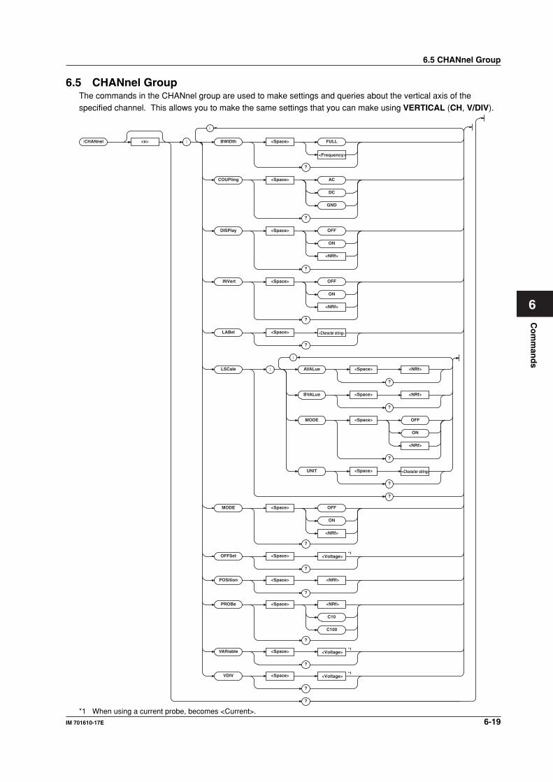
Co
mm
and
s
6-19IM 701610-17E
6
6.5 CHANnel GroupThe commands in the CHANnel group are used to make settings and queries about the vertical axis of thespecified channel. This allows you to make the same settings that you can make using VERTICAL (CH, V/DIV).
:CHANnel <x> : BWIDth <Space> FULL
?
COUPling <Space> AC
DC
GND
?
DISPlay <Space> OFF
ON
<NRf>
?
INVert <Space> OFF
ON
<NRf>
?
LABel <Space> <Character string>
<Frequency>
<Character string>
<Voltage>
<Voltage>
<Voltage>
?
LSCale : AVALue <Space> <NRf>
?
BVALue <Space> <NRf>
?
MODE <Space> OFF
ON
<NRf>
?
UNIT <Space>
?
?
MODE <Space> OFF
ON
<NRf>
C10
C100
?
OFFSet <Space>
?
POSition <Space> <NRf>
*1
*1
*1
?
PROBe <Space> <NRf>
?
VARiable <Space>
?
VDIV <Space>
?
?
;
;
*1 When using a current probe, becomes <Current>.
6.5 CHANnel Group
6-20 IM 701610-17E
:CHANnel<x>?Function Queries all vertical axis settings for the
specified channel.
Syntax :CHANnel<x>?
<x>=1 to 4 (or 1 to 2 for the DL1620)
Example :CHANNEL? -> :CHANNEL1:DISPLAY 1;
VDIV 50.000E+00;POSITION 0.00;
COUPLING DC;PROBE 10;
OFFSET 0.0E+00;
BWIDTH FULL;INVERT 0;
VARIABLE 50.000E+00;
LSCALE:MODE 0;AVALUE 1.00000E+00;
BVALUE 0.00000E+00;
UNIT “V”;:CHANNEL1:
LABEL “CH1”
:CHANnel<x>:BWIDthFunction Sets the input filter of each channel or queries
the current setting.
Syntax :CHANnel<x>:BWIDth FULL|
<frequency>
:CHANnel<x>:BWIDth?
<x>=1 to 4 (or 1 to 2 for the DL1620)
<frequency>=20 MHz, 1.28 MHz,
640 kHz, 320 KHz, 160 KHz, 80 kHz,
20 kHz, 10 kHz
Example :CHANNEL1:BWIDTH FULL
:CHANNEL1:BWIDTH? -> :CHANNEL1:
BWIDTH FULL
:CHANnel<x>:COUPlingFunction Sets the input coupling of each channel or
queries the current setting.
Syntax :CHANnel<x>:COUPling AC|DC|GND
:CHANnel<x>:COUPling?
<x>=1 to 4 (or 1 to 2 for the DL1620)
Example :CHANNEL1:COUPLING DC
:CHANNEL1:COUPLING? -> :CHANNEL1:
COUPLING DC
:CHANnel<x>:DISPlayFunction Sets/queries display ON/OFF for the specified
channel.
Syntax :CHANnel<x>:DISPlay <Boolean>
:CHANnel<x>:DISPlay?
<x>=1 to 4 (or 1 to 2 for the DL1620)
Example :CHANNEL1:DISPLAY ON
:CHANNEL1:DISPLAY? -> :CHANNEL1:
DISPLAY 1
Description The same function can be performed using
":CHANnel<x>:MODE."
6.5 CHANnel Group
:CHANnel<x>:INVertFunction Turns the invert mode ON/OFF or queries the
current setting.
Syntax :CHANnel<x>:INVert <Boolean>
:CHANnel<x>:INVert?
<x>=1 to 4 (or 1 to 2 for the DL1620)
Example :CHANNEL1:INVERT ON
:CHANNEL1:INVERT? ->
:CHANNEL1:INVERT 1
:CHANnel<x>:LABelFunction Sets/queries the channel’s waveform label.
Syntax :CHANnel<x>:LABel <Character
string>
:CHANnel<x>:LABel?
<x>=1 to 4 (or 1 to 2 for the DL1620)
<Character string>=Within 8
characters.
Example :CHANNEL1:LABEL "CH1"
:CHANNEL1:LABEL? -> :CHANNEL1:
LABEL "CH1"
Description • Only characters and symbols on the
displayed keyboard are available for use in
the label.
• ASCII codes for "Ω" and "µ" are 1EH and
1FH, respectively.
:CHANnel<x>:LSCale?Function Queries all linear scaling settings.
Syntax :CHANnel<x>:LSCale?
<x>=1 to 4 (or 1 to 2 for the DL1620)
Example :CHANNEL1:LSCALE:MODE 1;
AVALUE 1.00000E+00;
BVALUE 0.00000E+00;UNIT "V"
:CHANnel<x>:LSCale:AVALueFunction Sets/queries the constant (coefficient) A of
linear scaling.
Syntax :CHANnel<x>:LSCale:AVALue <NRf>
:CHANnel<x>:LSCale:AVALue?
<x>=1 to 4 (or 1 to 2 for the DL1620)
<NRf>=–9.9999E+30 to 9.9999E+30
Example :CHANNEL1:LSCALE:AVALUE 10
:CHANNEL1:LSCALE:AVALUE? ->
:CHANNEL:LSCALE:AVALUE 10.0000E+00
6-21IM 701610-17E
Co
mm
and
s
6
6.5 CHANnel Group
:CHANnel<x>:LSCale:BVALueFunction Sets/queries the offset value B of linear scaling.
Syntax :CHANnel<x>:LSCale:BVALue <NRf>
:CHANnel<x>:LSCale:BVALue?
<x>=1 to 4 (or 1 to 2 for the DL1620)
<NRf>=–9.9999E+30 to 9.9999E+30
Example :CHANNEL1:LSCALE:BVALUE 10
:CHANNEL1:LSCALE:BVALUE? ->
:CHANNEL:LSCALE:BVALUE 10.0000E+00
:CHANnel<x>:LSCale:MODEFunction Sets/queries the ON/OFF condition of linear
scaling.
Syntax :CHANnel<x>:LSCale:MODE <Boolean>
:CHANnel<x>:LSCale:MODE?
<x>=1 to 4 (or 1 to 2 for the DL1620)
Example :CHANNEL1:LSCALE:MODE ON
:CHANNEL1:LSCALE:MODE? ->
:CHANNEL1:LSCALE:MODE 1
:CHANnel<x>:LSCale:UNITFunction Sets/queries the dimensional unit which is
appended to the linear scaling result.
Syntax :CHANnel<x>:LSCale:UNIT <Character
string>
:CHANnel<x>:LSCale:UNIT?
<x>=1 to 4 (or 1 to 2 for the DL1620)
<Character string>=Within to 4
characters.
Example :CHANNEL1:LSCALE:UNIT "EU"
:CHANNEL1:LSCALE:UNIT? ->
:CHANNEL1:LSCALE:UNIT "EU"
Description • Only the characters and symbols on the
keyboard that appear on the instrument’s
screen can be used.
• ASCII codes for "Ω" and "µ" are 1EH and
1FH, respectively.
• This unit will not affect the scaled value in
any way.
:CHANnel<x>:MODEFunction Sets/queries display ON/OFF for the specified
channel.
Syntax :CHANnel<x>:MODE <Boolean>
:CHANnel<x>:MODE?
<x>=1 to 4 (or 1 to 2 for the DL1620)
Example :CHANNEL1:MODE ON
:CHANNEL1:MODE? -> :CHANNEL1:MODE 1
Description The same function can be performed using
":CHANnel<x>:DISPlay."
:CHANnel<x>:OFFSetFunction Sets/queries the offset voltage, when the
voltage module is installed at the channel (slot).
Syntax :CHANnel<x>:OFFSet <Voltage>
:CHANnel<x>:OFFSet?
<x>=1 to 4 (or 1 to 2 for the DL1620)
<Voltage>=See the IM701610-01E
User's Manual.
Example :CHANNEL1:OFFSET 0V
:CHANNEL1:OFFSET? -> :CHANNEL1:
OFFSET 0.000E+00
Description When set to the current probe, sets the
<Current> value or queries the current setting.
:CHANnel<x>:POSitionFunction Sets/queries the vertical position, when the
voltage module is installed at the channel (slot).
Syntax :CHANnel<x>:POSition <NRf>
:CHANnel<x>:POSition?
<x>=1 to 4 (or 1 to 2 for the DL1620)
<NRf>=–4.00 to 4.00div (in 1/100
steps)
Example :CHANNEL1:POSITION 1
:CHANNEL1:POSITION? -> :CHANNEL1:
POSITION 1.00E+00
:CHANnel<x>:PROBeFunction Sets/queries the probe attenuation.
Syntax :CHANnel<x>:PROBe <NRf|C10|C100>
:CHANnel<x>:PROBe?
<x>=1 to 4 (or 1 to 2 for the DL1620)
<NRf>=1,10,100,1000 (See the
IM701610-01E User's Manual)
Example :CHANNEL1:PROBE 1
:CHANNEL1:PROBE? -> :CHANNEL1:
PROBE 1
Description When using a "700937" current probe, set to
"C10". When using a "701930" current probe,
set to "C100".
:CHANnel<x>:VARiableFunction Sets the voltage sensitivity in units of 0.01 of
the V/div setting for each channel or queries the
current setting.
Syntax :CHANnel<x>:VARiable <voltage>
:CHANnel<x>:VARiable?
<x>=1 to 4 (or 1 to 2 for the DL1620)
<voltage>=See the IM701610-01E
User's Manual.
Example :CHANNEL1:VARIABLE 1V
:CHANNEL1:VARIABLE? -> :CHANNEL1:
VARIABLE 1.000E+00
Description When set to the current probe, sets the
<Current> value or queries the current setting.
6-22 IM 701610-17E
:CHANnel<x>:VDIVFunction Sets/queries the voltage sensitivity (V/div).
Syntax :CHANnel<x>:VDIV <Voltage>
:CHANnel<x>:VDIV?
<x>=1 to 4 (or 1 to 2 for the DL1620)
<Voltage>=2 mV to 10 V
(Probe attenuation 1:1, See the
IM701610-01E User's Manual)
Example :CHANNEL1:VDIV 2V
:CHANNEL1:VDIV? -> :CHANNEL1:
VDIV 2.000E+00
Description When set to the current probe, sets the
<Current> value or queries the current setting.
6.6 CLEar GroupThe CLEar command is used to clear the trace. This allows you to perform the same operation that you can
perform using CLEAR TRACE on the front panel.:CLEar
:CLEarFunction Clears trace.
Syntax :CLEar
Example :CLEAR
6.5 CHANnel Group/6.6 CLEar Group

6-23IM 701610-17E
Co
mm
and
s
6
6.7 COMMunicate GroupThe commands in the COMMunicate group are used to make settings and queries about communications. Thereis no front panel key with this function.
:COMMunicate
;
:
?
OPSE
HEADer <Space> OFF
ON
<NRf>
<Space> <Register>
?
OPSR ?
OVERlap <Space> <Register>
?
VERBose <Space> OFF
ON
<NRf>
WAIT ? <Space> <Register>
?
STATus ?
?
LOCKout <Space> OFF
ON
<NRf>
?
REMote <Space> OFF
ON
<NRf>
?
:COMMunicate?Function Queries all communication settings.
Syntax :COMMunicate?
Example :COMMUNICATE? -> :COMMUNICATE:
HEADER 1;OPSE 2400;OVERLAP 2400;
VERBOSE 1
:COMMunicate:HEADerFunction Determines whether a header is to be added
(for example: CHANNEL1:VOLTAGE:PROBE
10) or not (example: 10) when sending a
response to a query; or queries the current
setting.
Syntax :COMMunicate:HEADer <Boolean>
:COMMunicate:HEADer?
Example :COMMUNICATE:HEADER ON
:COMMUNICATE:HEADER? ->
:COMMUNICATE:HEADER 1
:COMMunicate:LOCKoutFunction Sets/releases the local lockout.
Syntax :COMMunicate:LOCKout <Boolean>
:COMMunicate:LOCKout?
Example :COMMUNICATE:LOCKOUT ON
:COMMUNICATE:LOCKOUT? ->
:COMMUNICATE:LOCKOUT 1
Description This is an exclusive command for the serial
(RS-232) interface, USB interface, or network
interface. In the case of a GP-IB interface, only
an interface message is returned.
6.7 COMMunicate Group
6-24 IM 701610-17E
6.7 COMMunicate Group
:COMMunicate:OPSE
(Operation Pending Status Enable
register)Function Sets the overlap command to be used with
*OPC, *OPC?, and *WAI, or queries the current
setting.
Syntax :COMMunicate:OPSE <Register>
:COMMunicate:OPSE?
<Register>=0 to 65535, refer to the
figure on the next page.
Example :COMMUNICATE:OPSE 65535
:COMMUNICATE:OPSE? -> :COMMUNICATE:
OPSE 2400
Description In the above example, all bits are masked to
"1" so that all overlap commands can be used
by this command. However, bits that are fixed
as "0" cannot be set to "1," so only bits 5, 6,
8, and 11 are actually set to "1" and appears
as "1" when a query is made.
:COMMunicate:OPSR?
(Operation Pending Status Register)Function Inquires about the value in the operation
pending status register.
Syntax :COMMunicate:OPSR?
Example :COMMUNICATE:OPSR? -> 0
Description For a description of the operation pending
status register, refer to the figure on the next
page.
:COMMunicate:OVERlapFunction Selects/queries the commands enabled for
overlap.
Syntax :COMMunicate:OVERlap <Register>
:COMMunicate:OVERlap?
<Register>=0 to 65535, refer to the
figure on the next page.
Example :COMMUNICATE:OVERLAP 65535
:COMMUNICATE:OVERLAP? ->
:COMMUNICATE:OVERLAP 2400
Description • In the above example, all bits are set to "1"
so that all overlap commands can be used by
this command. However, bits that are fixed
as "0" cannot be set to "1," so only bits 5,
6, 8, and 11 are actually set to "1" and
appears as "1" when a query is made.
• COMMunicate: For the synchronization
method using "OVERlap," refer to page 5-
8.
• In the above example, bits 5, 6, 8, and 11 are
set to "1" so that all overlap commands can
be used by this command. (Refer to the
figure on the next page.)
:COMMunicate:REMoteFunction Sets remote/local. It is in remote mode when it
is set to ON.
Syntax :COMMunicate:REMote <Boolean>
:COMMunicate:REMote?
Example :COMMUNICATE:REMOTE ON
:COMMUNICATE:REMOTE? -> 1
Description This is an exclusive command for the serial
(RS-232) interface (option), USB interface, or
network interface. In the case of a GP-IB
interface, only an interface message is
returned.
:COMMunicate:STATus?Function Queries the circuit status.
Syntax :COMMunicate:STATus?
Example :COMMUNICATE:STATUS? ->
:COMMUNICATE:STATUS 0
Description Status-bit meanings are as follows.
Bit GP-IB Serial (RS-232)
0 Unrecoverable Parity error
transmission error
1 Always 0 Framing error
2 Always 0 Break character
detected
3 to Always 0 Always 0
USB/Network interface: Always 0
Status bit sets when cause occurs, and clears
when read.
:COMMunicate:VERBoseFunction Determines whether a response to a query is to
be returned in full form (for example:
CHANNEL1:VOLTAGE:PROBE 10) or in
abbreviated form (for example: CHAN:PROB
10), or queries the current setting.
Syntax :COMMunicate:VERBose <Boolean>
:COMMunicate:VERBose?
Example :COMMUNICATE:VERBOSE ON
:COMMUNICATE:VERBOSE? ->
:COMMUNICATE:VERBOSE 1
:COMMunicate:WAITFunction Waits until one of the specified extended events
occurs.
Syntax :COMMunicate:WAIT <Register>
<Register>=0 to 65535 (Extended
event register; refer to page 7-4.)
Example :COMMUNICATE:WAIT 65535
Description COMMunicate: For a description of the
synchronizing method using "WAIT," refer to
page 5-8.
6-25IM 701610-17E
Co
mm
and
s
6
:COMMunicate:WAIT?Function Generates a response when one of the
specified extended events occurs.
Syntax :COMMunicate:WAIT? <Register>
<Register>=0 to 65535 (Extended
event register; refer to page 7-4.)
Example :COMMUNICATE:WAIT? 65535 -> 1
Operation pending status register/overlap
enable register15 14 13 12 11 10 9 8 7 6 5 4 3 2 1 00 0 0 0 SCH 0 0 HST 0 ACS 0 0 0 0 0PRN
When bit 5 (PRN)=1:
Printer operation not completed
When bit 6 (ACS)=1:
Medium not accessed
When bit 8 (HST)=1:
History search not completed
When bit 11 (SCH)=1:
Edeg/pattern search not completed
6.7 COMMunicate Group
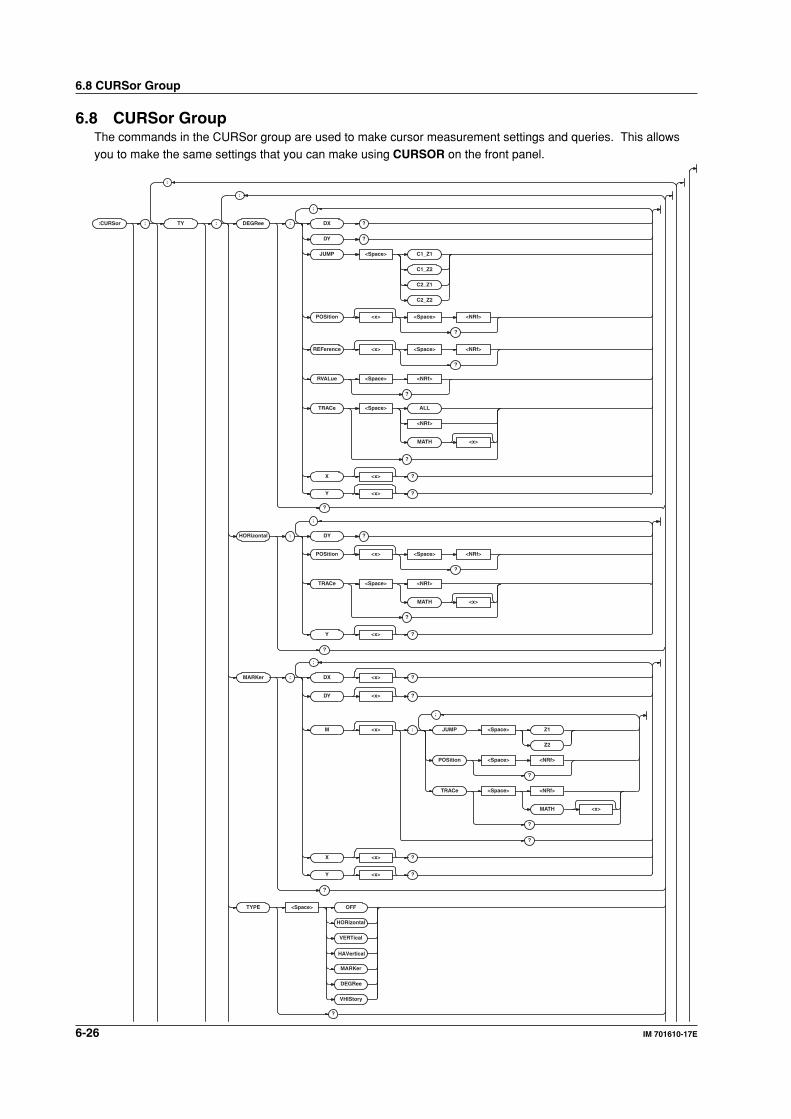
6-26 IM 701610-17E
6.8 CURSor Group
6.8 CURSor GroupThe commands in the CURSor group are used to make cursor measurement settings and queries. This allowsyou to make the same settings that you can make using CURSOR on the front panel.
:CURSor : TY : DEGRee : DX ?
DY ?
JUMP <Space> C1_Z1
C1_Z2
C2_Z1
C2_Z2
POSition <x> <Space> <NRf>
?
REFerence <x> <Space> <NRf>
?
RVALue <Space> <NRf>
?
TRACe <Space> ALL
<NRf>
MATH <x>
?
X <x> ?
Y <x> ?
?
HORizontal : DY ?
POSition <x> <Space> <NRf>
?
TRACe <Space> <NRf>
MATH <x>
?
Y <x> ?
?
;
;
;
;
MARKer : DX <x> ?
DY <x> ?
M <x> : JUMP <Space> Z1
Z2
POSition <Space> <NRf>
?
TRACe <Space> <NRf>
MATH <x>
?
?
X <x> ?
Y <x> ?
?
;
;
TYPE <Space> OFF
HORizontal
VERTical
HAVertical
MARKer
DEGRee
VHIStory
?
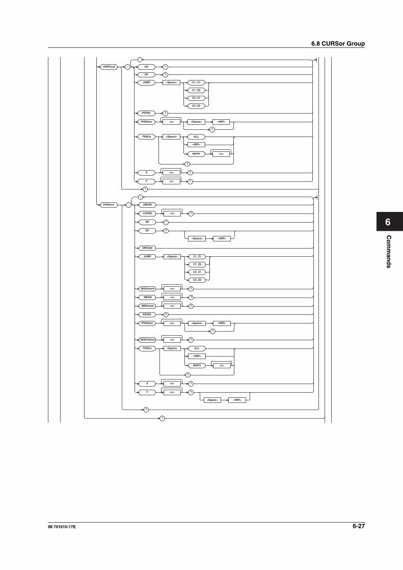
Co
mm
and
s
6-27IM 701610-17E
6
VERTical : DX ?
DY ?
DX ?
DY ?
EXECute
JUMP <Space> C1_Z1
C1_Z2
C2_Z1
C2_Z2
PERDt ?
POSition <x> <Space> <NRf>
?
<Space> <NRf>
TRACe <Space> ALL
<NRf>
MATH <x>
?
X <x> ?
Y
PERDt ?
<x> ?
?
?
;
POSition <x> <Space> <NRf>
?
TRACe <Space> ALL
<NRf>
MATH <x>
?
JUMP <Space>
<Space> <NRf>
VHIStory : ABORt
COUNt <x> ?
MAXimum <x> ?
MEAN <x> ?
MINimum <x> ?
SDEViation <x> ?
C1_Z1
C1_Z2
C2_Z1
C2_Z2
X <x> ?
Y <x> ?
?
;
6.8 CURSor Group
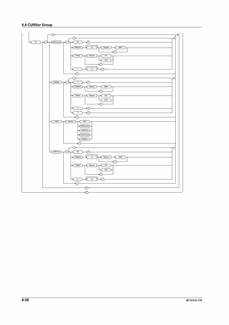
6-28 IM 701610-17E
XY : HORizontal : DY ?
POSition <x> <Space> <NRf>
?
TRACe <Space> XY1
XY2
?
Y <x> ?
?
MARKer : T ?
POSition <Space> <NRf>
?
TRACe <Space> XY1
XY2
?
X ?
Y ?
?
TYPE <Space> OFF
HORizontal
VERTical
HAVertical
MARKer
?
;
;
;
VERTical : DX ?
POSition <x> <Space> <NRf>
?
TRACe <Space> XY1
XY2
?
X <x> ?
?
?
?
;
6.8 CURSor Group
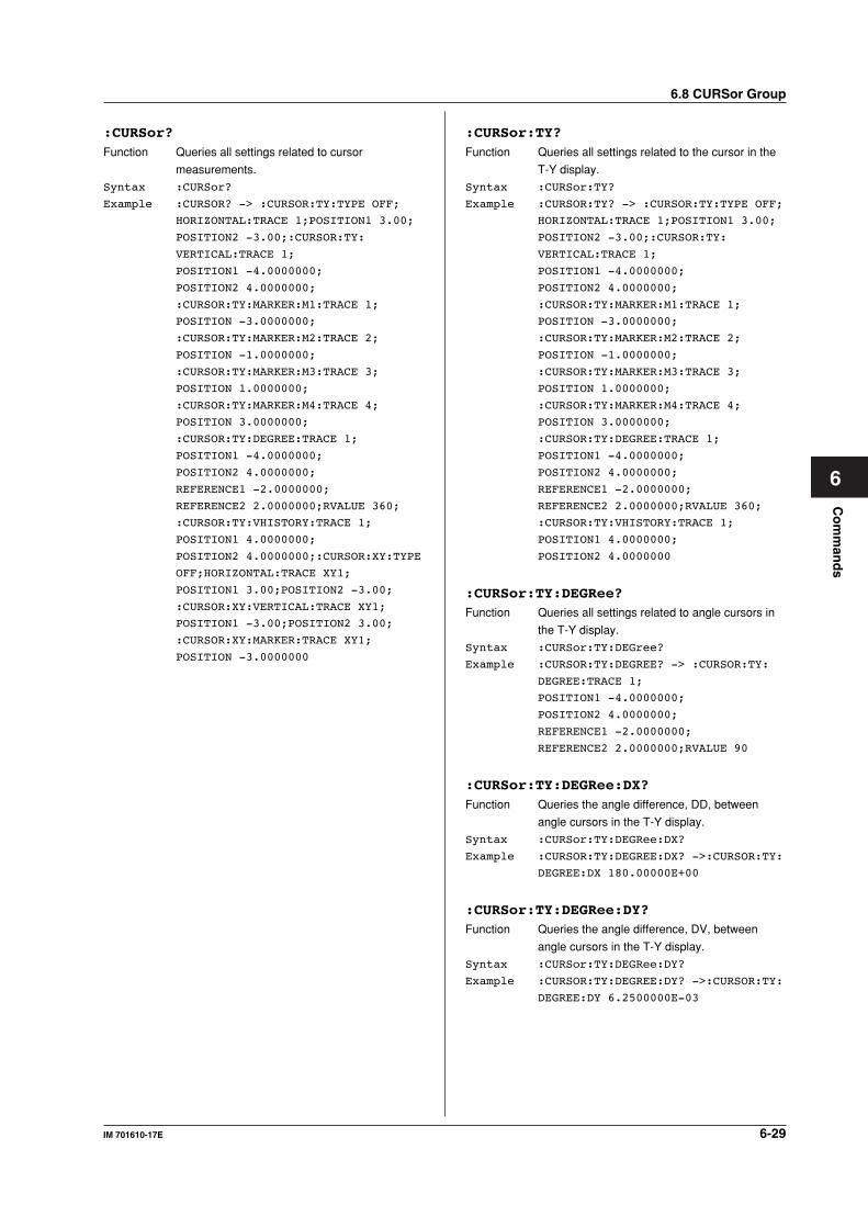
6-29IM 701610-17E
Co
mm
and
s
6
6.8 CURSor Group
:CURSor?Function Queries all settings related to cursor
measurements.
Syntax :CURSor?
Example :CURSOR? -> :CURSOR:TY:TYPE OFF;
HORIZONTAL:TRACE 1;POSITION1 3.00;
POSITION2 -3.00;:CURSOR:TY:
VERTICAL:TRACE 1;
POSITION1 -4.0000000;
POSITION2 4.0000000;
:CURSOR:TY:MARKER:M1:TRACE 1;
POSITION -3.0000000;
:CURSOR:TY:MARKER:M2:TRACE 2;
POSITION -1.0000000;
:CURSOR:TY:MARKER:M3:TRACE 3;
POSITION 1.0000000;
:CURSOR:TY:MARKER:M4:TRACE 4;
POSITION 3.0000000;
:CURSOR:TY:DEGREE:TRACE 1;
POSITION1 -4.0000000;
POSITION2 4.0000000;
REFERENCE1 -2.0000000;
REFERENCE2 2.0000000;RVALUE 360;
:CURSOR:TY:VHISTORY:TRACE 1;
POSITION1 4.0000000;
POSITION2 4.0000000;:CURSOR:XY:TYPE
OFF;HORIZONTAL:TRACE XY1;
POSITION1 3.00;POSITION2 -3.00;
:CURSOR:XY:VERTICAL:TRACE XY1;
POSITION1 -3.00;POSITION2 3.00;
:CURSOR:XY:MARKER:TRACE XY1;
POSITION -3.0000000
:CURSor:TY?Function Queries all settings related to the cursor in the
T-Y display.
Syntax :CURSor:TY?
Example :CURSOR:TY? -> :CURSOR:TY:TYPE OFF;
HORIZONTAL:TRACE 1;POSITION1 3.00;
POSITION2 -3.00;:CURSOR:TY:
VERTICAL:TRACE 1;
POSITION1 -4.0000000;
POSITION2 4.0000000;
:CURSOR:TY:MARKER:M1:TRACE 1;
POSITION -3.0000000;
:CURSOR:TY:MARKER:M2:TRACE 2;
POSITION -1.0000000;
:CURSOR:TY:MARKER:M3:TRACE 3;
POSITION 1.0000000;
:CURSOR:TY:MARKER:M4:TRACE 4;
POSITION 3.0000000;
:CURSOR:TY:DEGREE:TRACE 1;
POSITION1 -4.0000000;
POSITION2 4.0000000;
REFERENCE1 -2.0000000;
REFERENCE2 2.0000000;RVALUE 360;
:CURSOR:TY:VHISTORY:TRACE 1;
POSITION1 4.0000000;
POSITION2 4.0000000
:CURSor:TY:DEGRee?Function Queries all settings related to angle cursors in
the T-Y display.
Syntax :CURSor:TY:DEGree?
Example :CURSOR:TY:DEGREE? -> :CURSOR:TY:
DEGREE:TRACE 1;
POSITION1 -4.0000000;
POSITION2 4.0000000;
REFERENCE1 -2.0000000;
REFERENCE2 2.0000000;RVALUE 90
:CURSor:TY:DEGRee:DX?Function Queries the angle difference, DD, between
angle cursors in the T-Y display.
Syntax :CURSor:TY:DEGRee:DX?
Example :CURSOR:TY:DEGREE:DX? ->:CURSOR:TY:
DEGREE:DX 180.00000E+00
:CURSor:TY:DEGRee:DY?Function Queries the angle difference, DV, between
angle cursors in the T-Y display.
Syntax :CURSor:TY:DEGRee:DY?
Example :CURSOR:TY:DEGREE:DY? ->:CURSOR:TY:
DEGREE:DY 6.2500000E-03
6-30 IM 701610-17E
:CURSor:TY:DEGRee:TRACeFunction Sets the waveform on which to use the angle
cursor in the T-Y display or queries the current
setting.
Syntax :CURSor:TY:DEGRee:TRACe <NRf>|
MATH<x>|ALL
:CURSor:TY:DEGRee:TRACe?
<NRf>=1 to 4
<x>=1 or 2
Example :CURSOR:TY:DEGREE:TRACE 1
:CURSOR:TY:DEGREE:TRACE? ->:CURSOR:
TY:DEGREE:TRACE 1
:CURSor:TY:DEGRee:X<x>?Function Queries the angle at the angle cursor in the T-Y
display.
Syntax :CURSor:TY:DEGRee:X<x>?
<x>=1 or 2
Example (This is an example in which
Cursor1 is queried.)
:CURSOR:TY:DEGREE:X1? -> :CURSOR:
TY:DEGREE:X1 -120.00000E+00
:CURSor:TY:DEGRee:Y<x>?Function Queries the voltage value at the angle cursor in
the T-Y display.
Syntax :CURSor:TY:DEGRee:Y<x>?
<x>=1 or 2
Example (This is an example in which
Cursor1 is queried.)
:CURSOR:TY:DEGREE:Y1? -> :CURSOR:
TY:DEGREE:Y1 10.000000E-03
:CURSor:TY:HORizontal?Function Queries all settings related to H cursors in the
T-Y display.
Syntax :CURSor:TY:HORizontal?
Example :CURSOR:TY:HORIZONTAL? -> :CURSOR:
TY:HORIZONTAL:TRACE 1;
POSITION1 3.00;POSITION2 -3.00
:CURSor:TY:HORizontal:DY?Function Queries the Y-axis value between the H cursors
in the T-Y display.
Syntax :CURSor:TY:HORizontal:DY?
Example :CURSOR:TY:HORIZONTAL:DY? ->
:CURSOR:TY:HORIZONTAL:
DY 3.0000000E+00
Description When the linear scaling is ON, the scaled value
is queried.
:CURSor:TY:DEGRee:JUMPFunction Moves the angle cursor in the T-Y display to the
specified zoomed waveform.
Syntax :CURSor:TY:DEGRee:JUMP C1_Z1|
C1_Z2|C2_Z1|C2_Z2
Example :CURSOR:TY:DEGREE:JUMP C1_Z1
Description The cursor jumps to the center position of the
zoomed waveform.
C1 and C2 represent Cursor1 and Cursor2,
respectively.
:CURSor:TY:DEGRee:POSition<x>Function Sets the position of the angle cursor in the T-Y
display or queries the current setting.
Syntax :CURSor:TY:DEGRee:
POSition<x> <NRf>
:CURSor:TY:DEGRee:POSition<x>?
<x>=1 or 2
<NRf>=–5 to 5 (10 div/displayed
record length steps)
Example :CURSOR:TY:DEGREE:POSITION1 2
:CURSOR:TY:DEGREE:POSITION1? ->
:CURSOR:TY:DEGREE:
POSITION1 2.0000000
:CURSor:TY:DEGRee:REFerence<x>Function Sets the position of the angle reference start
point (Reference1) or the end point
(Reference2) in the T-Y display or queries the
current setting.
Syntax :CURSor:TY:DEGRee:
REFerence<x> <NRf>
:CURSor:TY:DEGRee:REFerence<x>?
<x>=1 or 2
<NRf>=–5 to 5 (10 div/displayed
record length steps)
Example :CURSOR:TY:DEGREE:REFERENCE1 -1
:CURSOR:TY:DEGREE:REFERENCE1? ->
:CURSOR:TY:DEGREE:
REFERENCE1 -1.0000000
:CURsor:TY:DEGRee:RVALueFunction Sets the angle reference width or queries the
current setting.
Syntax :CURSor:TY:DEGRee:RVALue <NRf>
:CURSor:TY:DEGRee:RVALue?
<NRf>=1 to 720
Example :CURSOR:TY:DEGREE:RVALUE 180
:CURSOR:TY:DEGREE:RVALUE? ->
:CURSOR:TY:DEGREE:RVALUE 180
6.8 CURSor Group
6-31IM 701610-17E
Co
mm
and
s
6
6.8 CURSor Group
:CURSor:TY:HORizontal:POSition<x>Function Sets the H cursor position in the T-Y display or
queries the current setting.
Syntax :CURSor:TY:HORizontal:
POSition<x> <NRf>
:CURSor:TY:HORizontal:POSition<x>?
<x>=1 or 2
<NRf>=–4 to 4div (1/100 steps)
Example :CURSOR:TY:HORIZONTAL:POSITION1 2
:CURSOR:TY:HORIZONTAL:POSITION1? ->
:CURSOR:TY:HORIZONTAL:
POSITION1 2.00
Description The <NRf> value is accurate to two digits
beyond the decimal.
:CURSor:TY:HORizontal:TRACeFunction Sets the waveform on which to use the H cursor
in the T-Y display or queries the current setting.
Syntax :CURSor:TY:HORizontal:TRACe <NRf>|
MATH<x>
:CURSor:TY:HORizontal:TRACe?
<NRf>=1 to 4 (or 1 to 2 for the
DL1620)
<x>=1 or 2 (or 1 for the DL1620)
Example :CURSOR:TY:HORIZONTAL:TRACE 1
:CURSOR:TY:HORIZONTAL:TRACE? ->
:CURSOR:TY:HORIZONTAL:TRACE 1
:CURSor:TY:HORizontal:Y<x>?Function Queries the Y-axis value of the H cursor in the
T-Y display.
Syntax :CURSor:TY:HORizontal:Y<x>?
<x>=1 or 2
Example :CURSOR:TY:HORIZONTAL:Y1? ->
:CURSOR:TY:HORIZONTAL:
Y1 -1.5000000E+00
Description When the linear scaling is ON, the scaled value
is queried.
:CURSor:TY:MARKer?Function Queries all settings related to marker cursors in
the T-Y display.
Syntax :CURSor:TY:MARKer?
Example :CURSOR:TY:MARKER? -> :CURSOR:TY:
MARKER:M1:TRACE 1;
POSITION -3.0000000;:CURSOR:TY:
MARKER:M2:TRACE 2;
POSITION -1.0000000;:CURSOR:TY:
MARKER:M3:TRACE 3;
POSITION 1.0000000;:CURSOR:TY:
MARKER:M4:TRACE 4;
POSITION 3.0000000
:CURSor:TY:MARKer:DX<x>?Function Queries the X-axis value between the marker
cursors in the T-Y display.
Syntax :CURSor:TY:MARKer:DX<x>?
<x>=1 to 4
Example :CURSOR:TY:MARKER:DX1? -> :CURSOR:
TY:MARKER:DX1 0.0000000E+00
Description • When the time base is set to internal clock
The query is for the time between the
markers in the time domain and the
frequency between the markers in the
frequency domain.
• When the time base is set to external clock
The number of points between the marker
cursors is queried.
:CURSor:TY:MARKer:DY<x>?Function Queries the physical value of the Y-axis
difference between the marker cursors in the T-
Y display.
Syntax :CURSor:TY:MARKer:DY<x>?
<x>=1 to 4
Example :CURSOR:TY:MARKER:DY2? -> :CURSOR:
TY:MARKER:DY2 500.00000E-03
Description When the linear scaling is ON, the scaled value
is queried.
:CURSor:TY:MARKer:M<x>?Function Queries all settings related to the specified
marker cursor.
Syntax :CURSor:TY:MARKer:M<x>?
<x>=1 to 4
Example :CURSOR:TY:MARKER:M1? -> :CURSOR:
TY:MARKER:M1:TRACE 1:
POSITION -3.0000000
:CURSor:TY:MARKer:M<x>:JUMPFunction Moves the marker cursor in the T-Y display to
the specified zoomed waveform.
Syntax :CURSor:MARKer:M<x>:JUMP Z1|Z2
<x>=1 to 4
Example :CURSOR:TY:MARKER:M1:JUMP Z1
Description The cursor jumps to the center position of the
zoomed waveform.
6-32 IM 701610-17E
:CURSor:TY:MARKer:M<x>:POSitionFunction Sets the X-axis position of the marker cursor in
the T-Y display or queries the current setting.
Syntax :CURSor:TY:MARKer:M<x>:
POSition <NRf>
:CURSor:TY:MARKer:M<x>:POSition?
<x>=1 to 4
<NRf>=–5 to 5 div (10 div/displayed
record length steps)
Example :CURSOR:TY:MARKER:M1:POSITION -1
:CURSOR:TY:MARKER:M1:POSITION? ->
:CURSOR:TY:MARKER:M1:
POSITION -1.0000000
:CURSor:TY:MARKer:M<x>:TRACeFunction Sets the waveform on which to use the marker
cursor in the T-Y display or queries the current
setting.
Syntax :CURSor:TY:MARKer:M<x>:
TRACe <NRf>|MATH<x>
:CURSor:TY:MARKer:M<x>:TRACe?
<x>=1 to 4
<NRf>=1 to 4 (or 1 to 2 for the
DL1620)
The <x> in MATH<x>=1 or 2(or 1 for
the DL1620)
Example :CURSOR:TY:MARKER:M1:TRACE 1
:CURSOR:TY:MARKER:M1:TRACE? ->
:CURSOR:TY:MARKER:M1:TRACE 1
:CURSor:TY:MARKer:X<x>?Function Queries the X-axis position of the marker cursor
in the T-Y display.
Syntax :CURSor:TY:MARKer:X<x>?
<x>=1 to 4
Example :CURSOR:TY:MARKER:X1? -> :CURSOR:
TY:MARKER:X1 -4.5000E-03
Description • When the time base is set to internal clock
The query is for the time in the time domain
and frequency in the frequency domain.
• When the time base is set to external
clock
The query is for the number of points with
respect to delay 0 in the time domain and the
number of points from the beginning of the
memory in the frequency domain.
:CURSor:TY:MARKer:Y<x>?Function Queries the Y-axis position of the marker cursor
in the T-Y display.
Syntax :CURSor:TY:MARKer:Y<x>?
<x>=1 to 4
Example :CURSOR:TY:MARKER:Y1? -> :CURSOR:
TY:MARKER:Y1 1.5000E-03
Description When the linear scaling is ON, the scaled value
is queried.
6.8 CURSor Group
:CURSor:TY:TYPEFunction Sets the type of cursor in the T-Y display or
queries the current setting.
Syntax :CURSor:TY:TYPE OFF|HORizontal|
VERTical|MARKer|DEGRee|HAVertical|
VHIStory
:CURSor:TY:TYPE?
Example :CURSOR:TY:TYPE HORIZONTAL
:CURSor:TY:TYPE? -> :CURSOR:TY:
TYPE HORIZONTAL
:CURSor:TY:VERTical?Function Queries all settings related to V cursors in the
T-Y display.
Syntax :CURSor:TY:VERTical?
Example :CURSOR:TY:VERTICAL -> :CURSOR:TY:
VERTICAL:TRACE 1;
POSITION1 -4.0000000;
POSITION2 4.0000000
:CURSor:TY:VERTical:DX?Function Queries the X-axis value between V cursors in
the T-Y display.
Syntax :CURSor:TY:VERTical:DX?
Example :CURSOR:TY:VERTICAL:DX? -> :CURSOR:
TY:VERTICAL:DX 2.50E-06
Description • When the time base is set to internal clock
The query is for the time between the
markers in the time domain and the
frequency between the markers in the
frequency domain.
• When the time base is set to external clock
The number of points between the marker
cursors is queried.
:CURSor:TY:VERTical:DY?Function Queries the Y-axis value between V cursors in
the T-Y display.
Syntax :CURSor:TY:VERTical:DY?
Example :CURSOR:TY:VERTICAL:DY? -> :CURSOR:
TY:VERTICAL:DY 1.50E+03
Description When the linear scaling of the Y trace is ON,
the scaled value is queried.
:CURSor:TY:VERTical:JUMPFunction Moves the V cursor in the T-Y display to the
specified zoomed waveform.
Syntax :CURSor:TY:VERTical:JUMP C1_Z1|
C1_Z2|C2_Z1|C2_Z2
Example :CURSOR:TY:VERTICAL:JUMP C1_Z1
Description The cursor jumps to the center position of the
zoomed waveform.
C1 and C2 represent V cursors, Cursor1 and
Cursor2, respectively.
6-33IM 701610-17E
Co
mm
and
s
6
:CURSor:TY:VERTical:PERDt?Function Queries the 1/DT value between V cursors in
the T-Y display.
Syntax :CURSor:TY:VERTical:PERDt?
Example :CURSOR:TY:VERTICAL:PERDT? ->
:CURSOR:TY:VERTICAL:PERDT 2.50E+06
Description When the specified trace is in the frequency
domain, "NAN(Not A Number)" is returned.
:CURSor:TY:VERTical:POSition<x>Function Sets the V cursor position in the T-Y display or
queries the current setting.
Syntax :CURSor:TY:VERTical:POSition<x>
<NRf>
:CURSor:TY:VERTical:POSition<x>?
<x>=1 or 2
<NRf>=–5 to 5 div (10 div/displayed
record length steps)
Example :CURSOR:TY:VERTICAL:POSITION1 2
:CURSOR:TY:VERTICAL:POSITION1? ->
:CURSOR:TY:VERTICAL:
POSITION1 2.00E+00
:CURSor:TY:VERTical:TRACeFunction Sets the waveform on which to use the V cursor
in the T-Y display or queries the current setting.
Syntax :CURSor:TY:VERTical:TRACe <NRf>|
MATH<x>|ALL
:CURSor:TY:VERTical:TRACe?
<NRf>=1 to 4 (or 1 to 2 for the
DL1620)
<x>=1 or 2 (or 1 for the DL1620)
Example :CURSOR:TY:VERTICAL:TRACE 1
:CURSOR:TY:VERTICAL:TRACE? ->
:CURSOR:TY:VERTICAL:TRACE 1
:CURSor:TY:VERTical:X<x>?Function Queries the X-axis position of the V cursor in
the T-Y display.
Syntax :CURSor:TY:VERTical:X<x>?
<x>=1 or 2
Example :CURSOR:TY:VERTICAL:X1?TY::CURSOR:
TY:VERTICAL:X1 -2.50E-06
Description • When the time base is set to internal clock
The query is for the time in the time domain
and frequency in the frequency domain.
• When the time base is set to external
clock
The query is for the number of points with
respect to delay 0 in the time domain and the
number of points from the beginning of the
memory in the frequency domain.
6.8 CURSor Group
:CURSor:TY:VERTical:Y<x>?Function Queries the Y-axis position of the V cursor in
the T-Y display.
Syntax :CURSor:TY:VERTical:Y<x>?
<x>=1 or 2
Example :CURSOR:TY:VERTICAL:Y1? -> :CURSOR:
TY:VERTICAL:Y1 2.50E+03
:CURSor:TY:VHIStory?Function Queries all settings related to the V history
cursor in the T-Y display.
Syntax :CURSor:TY:VHIStory?
Example :CURSOR:TY:VHISTORY? ->
:CURSOR:TY:VHISTORY:TRACE 1;
POSITION1 4.0000000;
POSITION2 4.0000000
:CURSor:TY:VHIStory:ABORtFunction Aborts the statistical processing within the
historical data of V history cursor values in the
T-Y display.
Syntax :CURSor:TY:VHIStory:ABORt
Example :CURSOR:TY:VHISTORY:ABORT
:CURSor:TY:VHIStory:COUNt<x>?Function Queries the number of statistical processing of
V history cursor values in the T-Y display.
Syntax :CURSor:TY:VHIStory:COUNt<x>?
<x> = 1 to 2
Example :CURSOR:TY:VHISTORY:COUNT1? -> 10
:CURSor:TY:VHIStory:DX?Function Queries the X-axis value between V history
cursors in the T-Y display.
Syntax :CURSor:TY:VHIStory:DX?
Example :CURSOR:TY:VHISTORY:DX? ->
8.0000000E-03
Description This message queries the X-axis value between
cursors after executing
":CURSor:VHIStory:EXECute".
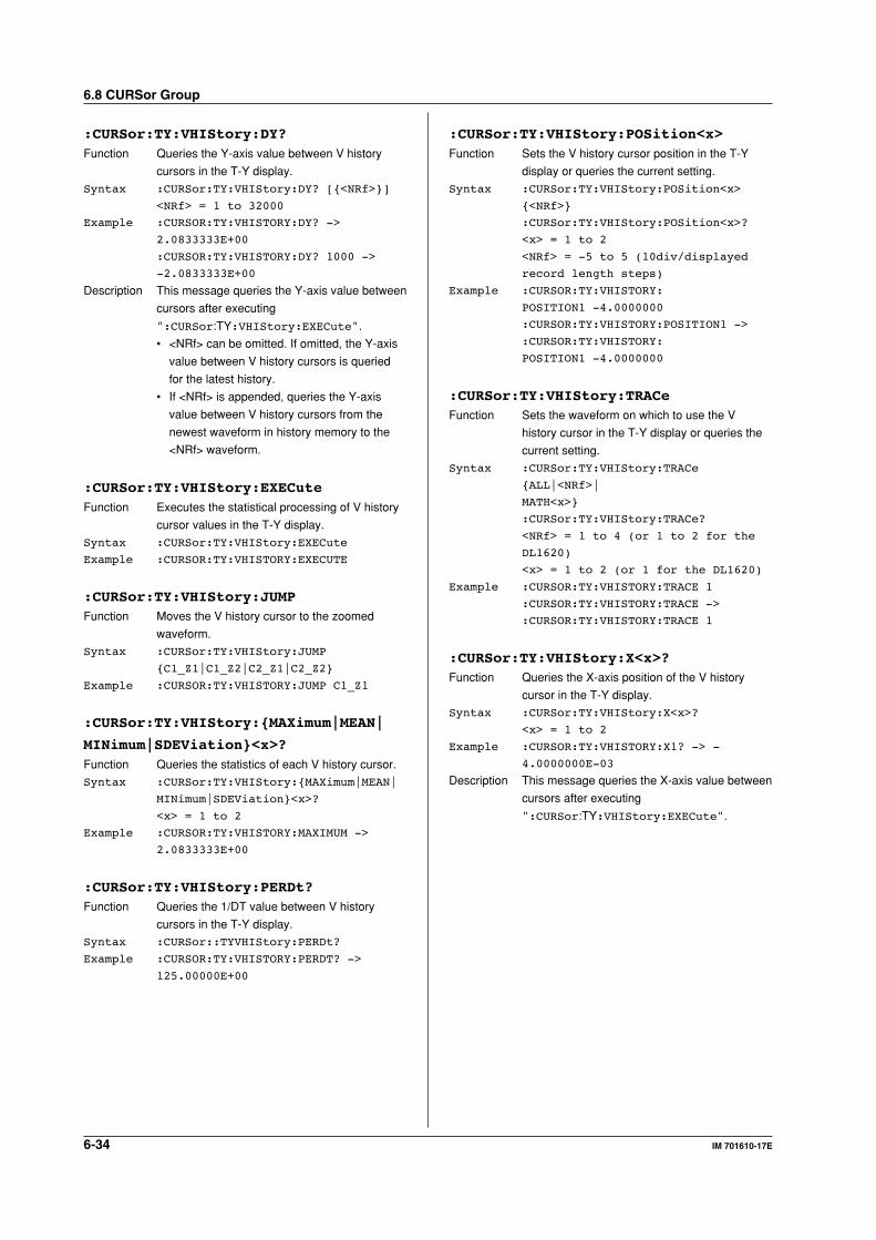
6-34 IM 701610-17E
:CURSor:TY:VHIStory:DY?Function Queries the Y-axis value between V history
cursors in the T-Y display.
Syntax :CURSor:TY:VHIStory:DY? [<NRf>]
<NRf> = 1 to 32000
Example :CURSOR:TY:VHISTORY:DY? ->
2.0833333E+00
:CURSOR:TY:VHISTORY:DY? 1000 ->
-2.0833333E+00
Description This message queries the Y-axis value between
cursors after executing
":CURSor:TY:VHIStory:EXECute".
• <NRf> can be omitted. If omitted, the Y-axis
value between V history cursors is queried
for the latest history.
• If <NRf> is appended, queries the Y-axis
value between V history cursors from the
newest waveform in history memory to the
<NRf> waveform.
:CURSor:TY:VHIStory:EXECuteFunction Executes the statistical processing of V history
cursor values in the T-Y display.
Syntax :CURSor:TY:VHIStory:EXECute
Example :CURSOR:TY:VHISTORY:EXECUTE
:CURSor:TY:VHIStory:JUMPFunction Moves the V history cursor to the zoomed
waveform.
Syntax :CURSor:TY:VHIStory:JUMP
C1_Z1|C1_Z2|C2_Z1|C2_Z2
Example :CURSOR:TY:VHISTORY:JUMP C1_Z1
:CURSor:TY:VHIStory:MAXimum|MEAN|
MINimum|SDEViation<x>?Function Queries the statistics of each V history cursor.
Syntax :CURSor:TY:VHIStory:MAXimum|MEAN|
MINimum|SDEViation<x>?
<x> = 1 to 2
Example :CURSOR:TY:VHISTORY:MAXIMUM ->
2.0833333E+00
:CURSor:TY:VHIStory:PERDt?Function Queries the 1/DT value between V history
cursors in the T-Y display.
Syntax :CURSor::TYVHIStory:PERDt?
Example :CURSOR:TY:VHISTORY:PERDT? ->
125.00000E+00
:CURSor:TY:VHIStory:POSition<x>Function Sets the V history cursor position in the T-Y
display or queries the current setting.
Syntax :CURSor:TY:VHIStory:POSition<x>
<NRf>
:CURSor:TY:VHIStory:POSition<x>?
<x> = 1 to 2
<NRf> = -5 to 5 (10div/displayed
record length steps)
Example :CURSOR:TY:VHISTORY:
POSITION1 -4.0000000
:CURSOR:TY:VHISTORY:POSITION1 ->
:CURSOR:TY:VHISTORY:
POSITION1 -4.0000000
:CURSor:TY:VHIStory:TRACeFunction Sets the waveform on which to use the V
history cursor in the T-Y display or queries the
current setting.
Syntax :CURSor:TY:VHIStory:TRACe
ALL|<NRf>|
MATH<x>
:CURSor:TY:VHIStory:TRACe?
<NRf> = 1 to 4 (or 1 to 2 for the
DL1620)
<x> = 1 to 2 (or 1 for the DL1620)
Example :CURSOR:TY:VHISTORY:TRACE 1
:CURSOR:TY:VHISTORY:TRACE ->
:CURSOR:TY:VHISTORY:TRACE 1
:CURSor:TY:VHIStory:X<x>?Function Queries the X-axis position of the V history
cursor in the T-Y display.
Syntax :CURSor:TY:VHIStory:X<x>?
<x> = 1 to 2
Example :CURSOR:TY:VHISTORY:X1? -> -
4.0000000E-03
Description This message queries the X-axis value between
cursors after executing
":CURSor:TY:VHIStory:EXECute".
6.8 CURSor Group
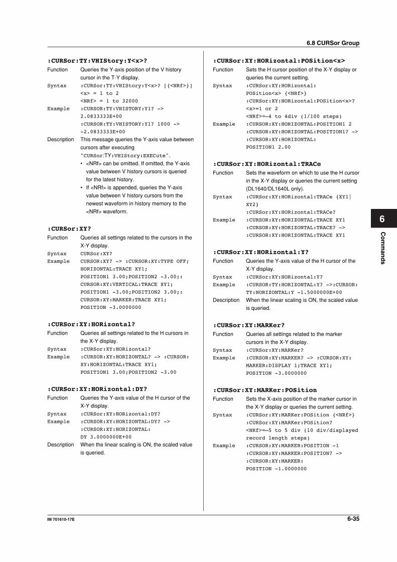
6-35IM 701610-17E
Co
mm
and
s
6
:CURSor:TY:VHIStory:Y<x>?Function Queries the Y-axis position of the V history
cursor in the T-Y display.
Syntax :CURSor:TY:VHIStory:Y<x>? [<NRf>]
<x> = 1 to 2
<NRf> = 1 to 32000
Example :CURSOR:TY:VHISTORY:Y1? ->
2.0833333E+00
:CURSOR:TY:VHISTORY:Y1? 1000 ->
-2.0833333E+00
Description This message queries the Y-axis value between
cursors after executing
"CURSor:TY:VHIStory:EXECute".
• <NRf> can be omitted. If omitted, the Y-axis
value between V history cursors is queried
for the latest history.
• If <NRf> is appended, queries the Y-axis
value between V history cursors from the
newest waveform in history memory to the
<NRf> waveform.
:CURSor:XY?Function Queries all settings related to the cursors in the
X-Y display.
Syntax CURSor:XY?
Example CURSOR:XY? -> :CURSOR:XY:TYPE OFF;
HORIZONTAL:TRACE XY1;
POSITION1 3.00;POSITION2 -3.00;:
CURSOR:XY:VERTICAL:TRACE XY1;
POSITION1 -3.00;POSITION2 3.00;:
CURSOR:XY:MARKER:TRACE XY1;
POSITION -3.0000000
:CURSor:XY:HORizontal?Function Queries all settings related to the H cursors in
the X-Y display.
Syntax :CURSor:XY:HORizontal?
Example :CURSOR:XY:HORIZONTAL? -> :CURSOR:
XY:HORIZONTAL:TRACE XY1;
POSITION1 3.00;POSITION2 -3.00
:CURSor:XY:HORizontal:DY?Function Queries the Y-axis value of the H cursor of the
X-Y display.
Syntax :CURSor:XY:HORizontal:DY?
Example :CURSOR:XY:HORIZONTAL:DY? ->
:CURSOR:XY:HORIZONTAL:
DY 3.0000000E+00
Description When the linear scaling is ON, the scaled value
is queried.
:CURSor:XY:HORizontal:POSition<x>Function Sets the H cursor position of the X-Y display or
queries the current setting.
Syntax :CURSor:XY:HORizontal:
POSition<x> <NRf>
:CURSor:XY:HORizontal:POSition<x>?
<x>=1 or 2
<NRf>=–4 to 4div (1/100 steps)
Example :CURSOR:XY:HORIZONTAL:POSITION1 2
:CURSOR:XY:HORIZONTAL:POSITION1? ->
:CURSOR:XY:HORIZONTAL:
POSITION1 2.00
:CURSor:XY:HORizontal:TRACeFunction Sets the waveform on which to use the H cursor
in the X-Y display or queries the current setting
(DL1640/DL1640L only).
Syntax :CURSor:XY:HORizontal:TRACe XY1|
XY2
:CURSor:XY:HORizontal:TRACe?
Example :CURSOR:XY:HORIZONTAL:TRACE XY1
:CURSOR:XY:HORIZONTAL:TRACE? ->
:CURSOR:XY:HORIZONTAL:TRACE XY1
:CURSor:XY:HORizontal:Y?Function Queries the Y-axis value of the H cursor of the
X-Y display.
Syntax :CURSor:XY:HORizontal:Y?
Example :CURSOR:TY:HORIZONTAL:Y? ->:CURSOR:
TY:HORIZONTAL:Y -1.5000000E+00
Description When the linear scaling is ON, the scaled value
is queried.
:CURSor:XY:MARKer?Function Queries all settings related to the marker
cursors in the X-Y display.
Syntax :CURSor:XY:MARKer?
Example :CURSOR:XY:MARKER? -> :CURSOR:XY:
MARKER:DISPLAY 1;TRACE XY1;
POSITION -3.0000000
:CURSor:XY:MARKer:POSitionFunction Sets the X-axis position of the marker cursor in
the X-Y display or queries the current setting.
Syntax :CURSor:XY:MARKer:POSition <NRf>
:CURSor:XY:MARKer:POSition?
<NRf>=–5 to 5 div (10 div/displayed
record length steps)
Example :CURSOR:XY:MARKER:POSITION -1
:CURSOR:XY:MARKER:POSITION? ->
:CURSOR:XY:MARKER:
POSITION -1.0000000
6.8 CURSor Group
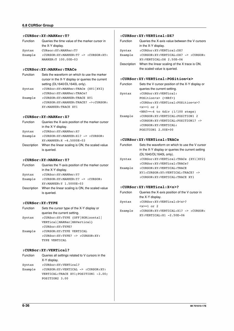
6-36 IM 701610-17E
:CURSor:XY:MARKer:T?Function Queries the time value of the marker cursor in
the X-Y display.
Syntax CURsor:XY:MARKer:T?
Example :CURSOR:XY:MARKER:T? -> :CURSOR:XY:
MARKER:T 100.00E-03
:CURSor:XY:MARKer:TRACeFunction Sets the waveform on which to use the marker
cursor in the X-Y display or queries the current
setting (DL1640/DL1640L only).
Syntax :CURSor:XY:MARKer:TRACe XY1|XY2
:CURSor:XY:MARKer:TRACe?
Example :CURSOR:XY:MARKER:TRACE XY1
:CURSOR:XY:MARKER:TRACE? ->:CURSOR:
XY:MARKER:TRACE XY1
:CURSor:XY:MARKer:X?Function Queries the X-axis position of the marker cursor
in the X-Y display.
Syntax :CURSor:XY:MARKer:X?
Example :CURSOR:XY:MARKER:X1? -> :CURSOR:
XY:MARKER:X -4.5000E-03
Description When the linear scaling is ON, the scaled value
is queried.
:CURSor:XY:MARKer:Y?Function Queries the Y-axis position of the marker cursor
in the X-Y display.
Syntax :CURSor:XY:MARKer:Y?
Example :CURSOR:XY:MARKER:Y? -> :CURSOR:
XY:MARKER:Y 1.5000E-03
Description When the linear scaling is ON, the scaled value
is queried.
:CURSor:XY:TYPEFunction Sets the cursor type of the X-Y display or
queries the current setting.
Syntax :CURSor:XY:TYPE OFF|HORizontal|
VERTical|MARKer|HAVertical
:CURSor:XY:TYPE?
Example :CURSOR:XY:TYPE VERTICAL
:CURSor:XY:TYPE? -> :CURSOR:XY:
TYPE VERTICAL
:CURSor:XY:VERTical?Function Queries all settings related to V cursors in the
X-Y display.
Syntax :CURSor:XY:VERTical?
Example :CURSOR:XY:VERTICAL -> :CURSOR:XY:
VERTICAL:TRACE XY1;POSITION1 -3.00;
POSITION2 3.00
:CURSor:XY:VERTical:DX?Function Queries the X-axis value between the V cursors
in the X-Y display.
Syntax :CURSor:XY:VERTical:DX?
Example :CURSOR:XY:VERTICAL:DX? -> :CURSOR:
XY:VERTICAL:DX 2.50E-06
Description When the linear scaling of the X trace is ON,
the scaled value is queried.
:CURSor:XY:VERTical:POSition<x>Function Sets the V cursor position of the X-Y display or
queries the current setting.
Syntax :CURSor:XY:VERTical:
POSition<x> <NRf>
:CURSor:XY:VERTical:POSition<x>?
<x>=1 or 2
<NRf>=–4 to 4div (1/100 steps)
Example :CURSOR:XY:VERTICAL:POSITION1 2
:CURSOR:XY:VERTICAL:POSITION1? ->
:CURSOR:XY:VERTICAL:
POSITION1 2.00E+00
:CURSor:XY:VERTical:TRACeFunction Sets the waveform on which to use the V cursor
in the X-Y display or queries the current setting
(DL1640/DL1640L only).
Syntax :CURSor:XY:VERTical:TRACe XY1|XY2
:CURSor:XY:VERTical:TRACe?
Example :CURSOR:XY:VERTICAL:TRACE
XY1:CURSOR:XY:VERTICAL:TRACE? ->
:CURSOR:XY:VERTICAL:TRACE XY1
:CURSor:XY:VERTical:X<x>?Function Queries the X-axis position of the V cursor in
the X-Y display.
Syntax :CURSor:XY:VERTical:X<x>?
<x>=1 or 2
Example :CURSOR:XY:VERTICAL:X1? -> :CURSOR:
XY:VERTICAL:X1 -2.50E-06
6.8 CURSor Group
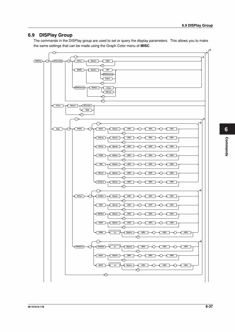
Co
mm
and
s
6-37IM 701610-17E
6
6.9 DISPlay Group
6.9 DISPlay GroupThe commands in the DISPlay group are used to set or query the display parameters. This allows you to makethe same settings that can be made using the Graph Color menu of MISC.
:DISPlay : ACCumlate : COLor <Space> <NRf>
?
MODE <Space> OFF
PERSistence
COLor
?
PERSistence <Space> <Time>
INFinity
?
COLor <Space>
RGB
INTensity
?
?
RGB :
;
;
MENU : BACK <Space> <NRf> , <NRf> , <NRf>
?
DIALog <Space> <NRf> , <NRf> , <NRf>
?
FOCus <Space> <NRf> , <NRf> , <NRf>
?
FORE <Space> <NRf> , <NRf> , <NRf>
?
LINE <Space> <NRf> , <NRf> , <NRf>
?
SELect <Space> <NRf> , <NRf> , <NRf>
?
SHADow <Space> <NRf> , <NRf> , <NRf>
?
OTHers : CURSor <Space> <NRf> , <NRf> , <NRf>
?
GRID <Space> <NRf> , <NRf> , <NRf>
?
MARKer <Space> <NRf> , <NRf> , <NRf>
?
SNAP <Space> <NRf> , <NRf> , <NRf>
?
ZONE <x> <Space> <NRf> , <NRf> , <NRf>
?
WAVeform : CHANnel <x> <Space> <NRf> , <NRf> , <NRf>
?
BACK <Space> <NRf> , <NRf> , <NRf>
?
MATH <x> <Space> <NRf> , <NRf> , <NRf>
?
;
;
;
;
?
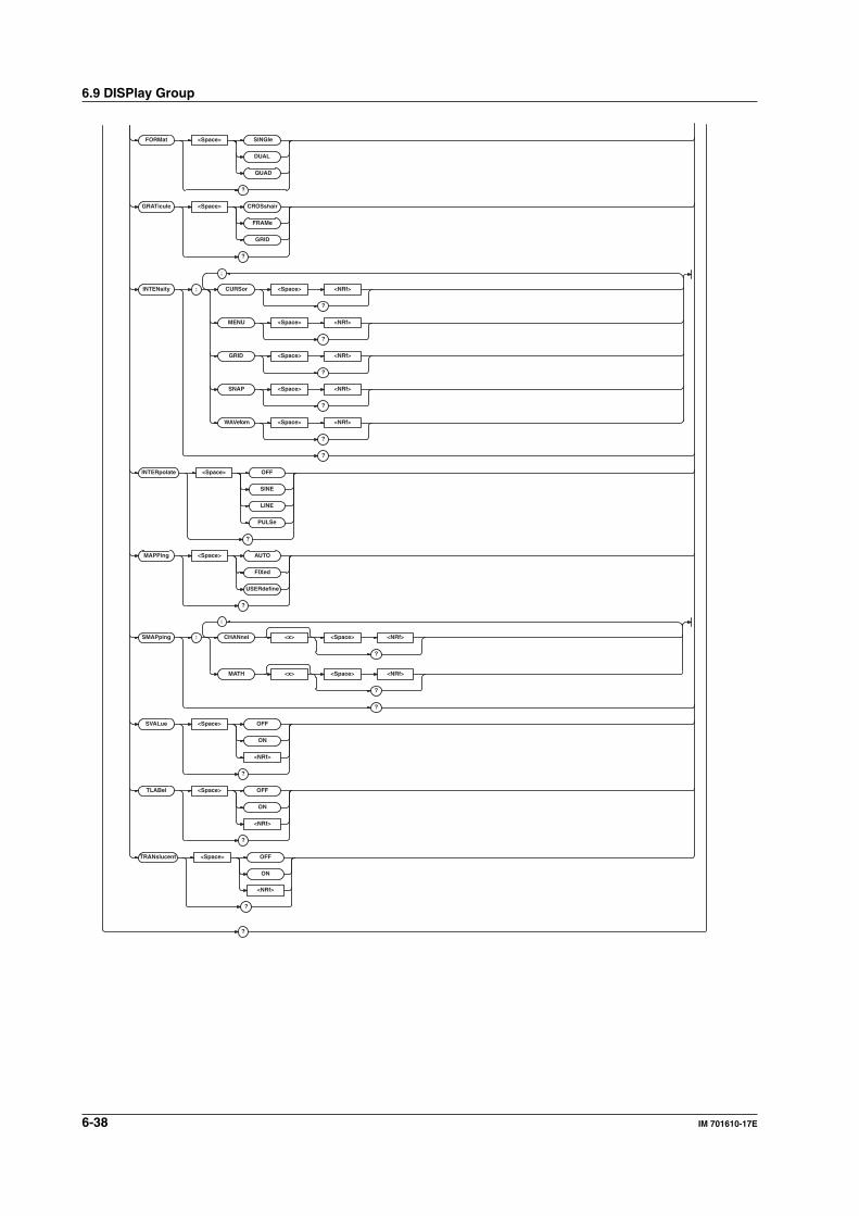
6-38 IM 701610-17E
FORMat <Space> SINGle
DUAL
QUAD
?
GRATicule <Space> CROSshair
FRAMe
GRID
?
INTENsity : CURSor <Space> <NRf>
?
MENU <Space> <NRf>
?
GRID <Space> <NRf>
?
SNAP <Space> <NRf>
?
WAVeforn <Space> <NRf>
?
?
INTERpolate <Space> OFF
SINE
LINE
PULSe
?
MAPPing <Space> AUTO
FIXed
USERdefine
?
SMAPping : CHANnel <x> <Space> <NRf>
?
MATH <x> <Space> <NRf>
?
?
SVALue <Space> OFF
ON
<NRf>
?
TLABel <Space> OFF
ON
<NRf>
?
TRANslucent <Space> OFF
ON
;
;
<NRf>
?
?
6.9 DISPlay Group
6-39IM 701610-17E
Co
mm
and
s
6
6.9 DISPlay Group
:DISPlay?Function Queries all display settings.
Syntax :DISPlay?
Example :DISPLAY? -> :DISPLAY:FORMAT QUAD;
INTERPOLATE SINE;GRATICULE GRID;
SVALUE 0;TLABEL 0;ACCUMLATE:
MODE OFF;PERSISTENCE 100.0E-03;
COLOR 16;:DISPLAY:TRANSLUCENT 0;
MAPPING AUTO;SMAPPING:CHANNEL1 0;
CHANNEL2 1;CHANNEL3 2;CHANNEL4 3;
MATH1 4;MATH2 5;:DISPLAY:
COLOR INTENSITY;INTENSITY:MENU 10;
WAVEFORM 10;SNAP 10;GRID 10;
CURSOR 10;:DISPLAY:RGB:MENU:
FORE 15,15,15;BACK 0,0,7;
FOCUS 0,0,7;SELECT 0,7,15;
DIALOG 7,7,7;SHADOW 0,0,0;
LINE 15,15,15;:DISPLAY:RGB:
WAVEFORM:CHANNEL1 15,15,0;
CHANNEL2 0,15,0;CHANNEL3 15,0,15;
CHANNEL4 0,15,15;MATH1 15,0,0;
MATH2 15,7,0;BACK 0,0,0;:DISPLAY:
RGB:OTHERS:SNAP 15,15,15;
ZONE1 0,0,15;ZONE2 15,4,11;
ZONE3 11,15,4;ZONE4 0,7,15;
GRID 8,8,8;CURSOR 13,13,13;
MARKER 15,15,15
:DISPlay:ACCumulate?Function Queries all accumulation settings.
Syntax :DISPlay:ACCumulate?
Example :DISPLAY:ACCUMULATE? -> :DISPLAY:
ACCUMULATE:MODE OFF;
PERSISTENCE 100.0E-03;COLOR 16
:DISPlay:ACCumulate:COLorFunction Sets/queries the color grading width.
Syntax :DISPlay:ACCumulate:COLor <NRf>
:DISPlay:ACCumulate:COLor?
<NRf>=2 to 2048 (in steps of 2n)
Example :DISPLAY:ACCUMULATE:COLOR 16
:DISPLAY:ACCUMULATE:COLOR? ->
:DISPLAY:ACCUMULATE:COLOR 16
:DISPlay:ACCumulate:MODEFunction Selects/queries the accumulation mode.
Syntax :DISPlay:ACCumulate:MODE COLor|
OFF|PERSistence
:DISPlay:ACCumulate:MODE?
Example :DISPLAY:ACCUMULATE:
MODE PERSISTENCE
:DISPLAY:ACCUMULATE:MODE? ->
:DISPLAY:ACCUMULATE:
MODE PERSISTENCE
:DISPlay:ACCumulate:PERSistenceFunction Sets/queries the accumulation time.
Syntax :DISPlay:ACCumulate:
PERSistence <Time>|INFinity
:DISPlay:ACCumulate:PERSistence?
<Time>=100 ms to 50 s (in 1-2-5
steps)
Example :DISPLAY:ACCUMULATE:
PERSISTENCE 100MS
:DISPLAY:ACCUMULATE:PERSISTENCE? ->
:DISPLAY:ACCUMULATE:
PERSISTENCE 100.0E-03
:DISPlay:COLorFunction Sets whether to change the screen color using
RGB or brightness or queries the current
setting.
Syntax :DISPlay:COLor INTensity|RGB
:DISPlay:COLor?
Example :DISPLAY:COLOR INTENSITY
:DISPLAY:COLOR? -> :DISPLAY:
COLOR INTENSITY
:DISPlay:RGB?Function Queries all settings related to the screen color.
Syntax :DISPlay:RGB?
Example :DISPLAY:RGB? -> :DISPLAY:RGB:MENU:
FORE 15,15,15;BACK 0,0,7;
FOCUS 0,0,7;SELECT 0,7,15;
DIALOG 7,7,7;SHADOW 0,0,0;
LINE 15,15,15;:DISPLAY:RGB:
WAVEFORM:CHANNEL1 15,15,0;
CHANNEL2 0,15,0;CHANNEL3 15,0,15;
CHANNEL4 0,15,15;MATH1 15,0,0;
MATH2 15,7,0;BACK 0,0,0;:DISPLAY:
RGB:OTHERS:SNAP 15,15,15;
ZONE1 0,0,15;ZONE2 15,4,11;
ZONE3 11,15,4;ZONE4 0,7,15;
GRID 8,8,8;CURSOR 13,13,13;
MARKER 15,15,15
:DISPlay:RGB:MENU?Function Queries all settings related to colors used in the
menu.
Syntax :DISPlay:RGB:MENU?
Example :DISPLAY:RGB:MENU? -> :WAVEFORM::
DISPLAY:RGB:MENU:FORE 15,15,15;
BACK 0,0,7;FOCUS 0,0,7;
SELECT 0,7,15;DIALOG 7,7,7;
SHADOW 0,0,0;LINE 15,15,15

6-40 IM 701610-17E
6.9 DISPlay Group
:DISPlay:RGB:MENU:BACK|DIALog|
FOCus|FORE|LINE|SELect|SHADowFunction Sets the color of the characters, background,
focus, select, dialog, shade, and lines of the
menu screen or queries the current setting.
Syntax :DISPlay:RGB:MENU:BACK|DIALog|
FOCus|FORE|LINE|SELect|
SHADow <NRf>,<NRf>,<NRf>
:DISPlay:RGB:MENU:BACK|DIALog|
FOCus|FORE|LINE|SELect|SHADow?
<NRf>=0 to 15 (R, G, B, in that
order)
Example :DISPlay:RGB:MENU:BACK 15,15,15
:DISPLAY:RGB:MENU:BACK? ->
:DISPLAY:RGB:MENU:BACK 15,15,15
Description Set the ":DISPlay:COLor" command to "RGB"
before executing this command.
:DISPlay:RGB:OTHers?Function Queries all settings related to the colors of other
items.
Syntax :DISPlay:RGB:OTHers?
Example :DISPLAY:RGB:OTHERS? -> :DISPLAY:
RGB:OTHERS:SNAP 15,15,15;
ZONE1 0,0,15;ZONE2 15,4,11;
ZONE3 11,15,4;ZONE4 0,7,15;
GRID 8,8,8;CURSOR 13,13,13;
MARKER 15,15,15
:DISPlay:RGB:OTHers:CURSor|GRID|
MARKer|SNAP|ZONE<x>Function Sets the color for cursors, grid, markers, and
snapshot waveforms or queries the current
setting.
Syntax :DISPlay:RGB:OTHers:CURSor|GRID|
MARKer|SNAP|ZONE<x> <NRf>,<NRf>,
<NRf>
:DISPlay:RGB:OTHers:CURSor|GRID|
MARKer|SNAP|ZONE<x>?
<x>=1 or 2
<NRf>=0 to 15 (R, G, B, in that
order)
Example :DISPLAY:RGB:OTHERS:CURSOR 0,0,0
:DISPLAY:RGB:OTHERS:CURSOR? ->
:DISPLAY:RGB:OTHERS:CURSOR 0,0,0
Description Set the ":DISPlay:COLor" command to "RGB"
before executing this command.
:DISPlay:RGB:WAVeform?Function Queries all settings related to the waveform
colors.
Syntax :DISPlay:RGB:WAVeform?
Example :DISPLAY:RGB:WAVEFORM? -> :DISPLAY:
RGB:WAVEFORM:CHANNEL1 15,15,0;
CHANNEL2 0,15,0;CHANNEL3 15,0,15;
CHANNEL4 0,15,15;MATH1 15,0,0;
MATH2 15,7,0;BACK 0,0,0
:DISPlay:RGB:WAVeform:CHANnel<x>|
BACK|MATH<x>Function Sets the colors for waveform, computation, and
logic channels and the background or queries
the current setting.
Syntax :DISPlay:RGB:WAVeform:CHANnel<x>|
BACK|MATH<x> <NRf>,<NRf>,<NRf>
:DISPlay:RGB:WAVeform:CHANnel<x>|
BACK|MATH<x>
The <x> in CHANnel<x>=1 to 4 (or 1
to 2 for the DL1620)
The <x> in MATH<x>=1 or 2 (or 1 for
the DL1620)
<NRf>=0 to 15 (R, G, B, in that
order)
Example :DISPLAY:RGB:WAVEFORM:
CHANNEL1 0,0,0
:DISPLAY:RGB:WAVEFORM:CHANNEL1? ->
:DISPLAY:RGB:WAVEFORM:
CHANNEL1 0,0,0
Description Set the ":DISPlay:COLor" command to "RGB"
before executing this command.
:DISPlay:FORMatFunction Sets/queries the display format.
Syntax :DISPlay:FORMat SINGle|DUAL|QUAD
:DISPlay:FORMat?
Example :DISPLAY:FORMAT QUAD
:DISPLAY:FORMAT? -> :DISPLAY:
FORMAT QUAD
Description QUAD cannot be use on the DL1620.
:DISPlay:GRATiculeFunction Sets/queries the graticule.
Syntax :DISPlay:GRATicule CROSshair|
FRAMe|GRID
:DISPlay:GRATicule?
Example :DISPLAY:GRATICULE GRID
:DISPLAY:GRATICULE? -> :DISPLAY:
GRATICULE GRID
:DISPlay:INTENsity?Function Queries all settings related to the brightness of
the displayed items.
Syntax :DISPlay:INTENsity?
Example :DISPLAY:INTENSITY? -> :DISPLAY:
INTENSITY:MENU 10;WAVeform 10;
SNAP 10;GRID 10;CURSOR 10
6-41IM 701610-17E
Co
mm
and
s
6
6.9 DISPlay Group
:DISPlay:INTENsity:CURSor|
MENU|GRID|SNAP|WAVeformFunction Sets the brightness of each display item or
queries the current setting.
Syntax :DISPlay:INTENsity:CURSor|MENU|
GRID|SNAP|WAVeform <NRf>
:DISPlay:INTENsity:CURSor|MENU|
GRID|SNAP|WAVeform?
<NRf>=1 to 15
Example (The following example is for the
cursor.)
:DISPLAY:INTENSITY:CURSOR 6
:DISPLAY:INTENSITY:CURSOR? ->
:DISPLAY:INTENSITY:CURSOR 6
Description Set the ":DISPlay:COLor" command to
"INTensity" before executing this command.
:DISPlay:INTERpolateFunction Selects/queries the interpolation method.
Syntax :DISPlay:INTerpolate LINE|OFF|
PULSe|SINE
:DISPlay:INTerpolate?
Example :DISPLAY:INTERPOLATE LINE
:DISPLAY:INTERPOLATE? -> :DISPLAY:
INTERPOLATE LINE
:DISPlay:MAPPingFunction Sets/queries the mapping mode.
Syntax :DISPlay:MAPPing AUTO|FIXed|
USERdefine
:DISPlay:MAPPing?
Example :DISPLAY:MAPPING AUTO
:DISPLAY:MAPPING? -> :DISPLAY:
MAPPING AUTO
:DISPlay:SMAPping?Function Queries all settings relating to the assignment
of the waveforms to the split window.
Syntax :DISPlay:SMAPping?
Example :DISPLAY:SMAPPING? -> :DISPLAY:
SMAPPING:CHANNEL1 0;CHANNEL2 1;
CHANNEL3 2;CHANNEL4 3;MATH1 4;
MATH2 5
:DISPlay:SMAPping:CHANnel<x>|
MATH<x> (Set Mapping)Function Sets/queries the assignment of the waveforms
to the split window.
Syntax :DISPlay:SMAPping:CHANnel<x>|
MATH<x> <NRf>
:DISPlay:SMAPping:CHANnel<x>|
MATH<x>?
CHANnel<x>=1 to 4 (or 1 to 2 for
the DL1620)
<x> of MATH<x>=1, 2 (or 1 for the
DL1620)
<NRf>=0 to 5 (or 0 to 2 for the
DL1620)
Example (Below is an example of CH1.)
:DISPLAY:SMAPPING:CHANNEL1
0:DISPLAY:SMAPPING:CHANNEL1? ->
:DISPLAY:SMAPPING:CHANNEL1 0
:DISPlay:SVALue (Scale VALUE)Function Selects/queries whether scaling values are
displayed.
Syntax :DISPlay:SVALue <Boolean>
:DISPlay:SVALue?
Example :DISPLAY:SVALUE OFF
:DISPLAY:SVALUE? -> :DISPLAY:
SVALUE 0
:DISPlay:TLABel (Trace LABEL)Function Selects/queries whether waveform labels are
displayed.
Syntax :DISPlay:TLABel <Boolean>
:DISPlay:TLABel?
Example :DISPLAY:TLABEL ON
:DISPLAY:TLABEL? -> :DISPLAY:
TLABEL 1
Description You can set a user defined waveform label
using the ":CHANnel<x>:LABel" command.
:DISPlay:TRANslucentFunction Sets/queries the ON/OFF condition of the
translucent mode of the pop-up menu.
Syntax :DISPlay:TRANslucent <Boolean>
:DISPlay:TRANslucent?
Example :DISPLAY:TRANSLUCEENT ON
:DISPLAY:TRANSLUCEENT? -> :DISPLAY:
TRANSLUCEENT 1
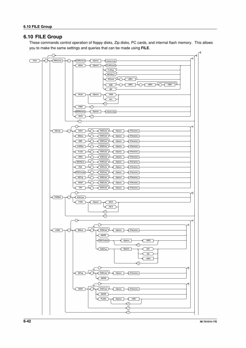
6-42 IM 701610-17E
6.10 FILE Group
6.10 FILE GroupThese commands control operation of floppy disks, Zip disks, PC cards, and internal flash memory. This allowsyou to make the same settings and queries that can be made using FILE.
:FILE :
FORMat : EXECute
;
;
TYPE <Space> DD72
HD14
?
?
LOAD : BINar y : EXECute
ABORt
SETup : EXECute
ABORt
SNAP : EXECute
ABORt
PLANe <Space> <NRf>
?
?
?
;
<Space> <Filename>
<Space> <Filename>
<Space> <Filename>
;
;
;
DELete : : EXECute <Space> <Filename>
: EXECute <Space> <Filename>
: EXECute <Space> <Filename>
: EXECute <Space> <Filename>
: EXECute <Space> <Filename>
: EXECute <Space> <Filename>
: EXECute <Space> <Filename>
: EXECute <Space> <Filename>
: EXECute <Space> <Filename>
: EXECute <Space> <Filename>
: EXECute <Space> <Filename>
ASCii
BINary
BMP
FLOat
MEASure
CURSor
PNG
POSTscript
SETup
SNAP
TIFF
DIRector y : CDIRector y <Space>
DRIVe <Space>
FILTer <Space> ITEM
ALL
?
FREE ?
MDIRector y <Space>
PA TH ?
?
<Character string>
<Character string>
;
: EXECute <Space> <Filename>JPEG
<Space>
<NRf>
OFF
ON
?
WSETup
?
<NRf>DESTination <Space>
FLAShmem
*1
*2
*1
FLOPpy
, <NRf>PCCard
ZIP*1
NETWork
*1,, <NRf><NRf>USB , <NRf>
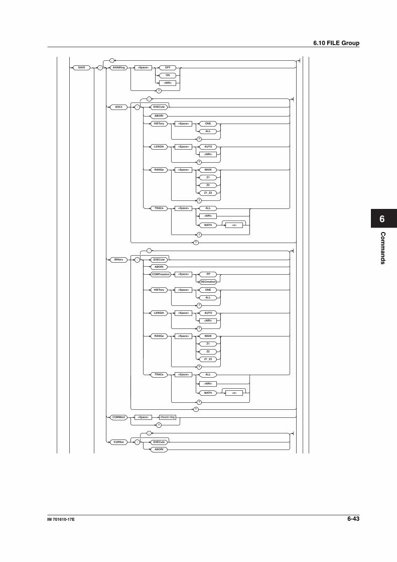
Co
mm
and
s
6-43IM 701610-17E
6
6.10 FILE Group
SAVE : ANAMing <Space> OFF
ON
<NRf>
?
ASCii : EXECute
ABORt
HISTor y <Space> ONE
ALL
?
RANGe <Space> MAIN
Z1
Z2
Z1_Z2
?
TRACe <Space> ALL
LENGth <Space> AUTO
?
<NRf>
LENGth <Space> AUTO
?
<NRf>
<NRf>
MATH <x>
?
?
BINar y :
ABORt
HISTor y <Space> ONE
ALL
?
RANGe <Space> MAIN
Z1
Z2
Z1_Z2
?
;
;
;
COMPression <Space> PP
DECimation
<NRf>
MATH <x>
?
?
COMMent <Space> <Character string>
?
TRACe <Space> ALL
EXECute
CURSor :
ABORt
;
EXECute
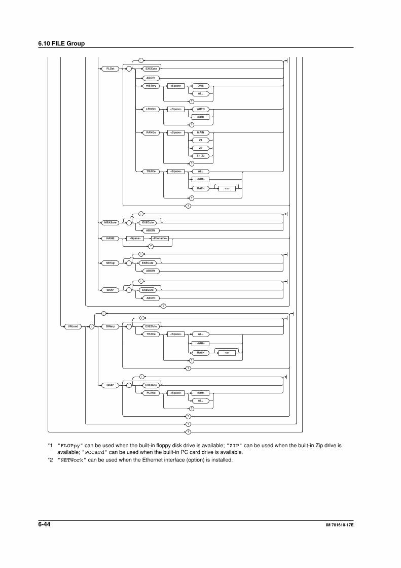
6-44 IM 701610-17E
FLOat : EXECute
ABORt
HISTor y <Space> ONE
ALL
?
RANGe <Space> MAIN
Z1
Z2
Z1_Z2
?
TRACe <Space> ALL
<NRf>
MATH <x>
?
?
MEASure : EXECute
ABORt
NAME <Space> <Filename>
?
SETup : EXECute
ABORt
SNAP : EXECute
ABORt
?
;
<NRf>
MATH <x>
?
?
SNAP : EXECute
PLANe <Space> <NRf>
ALL
?
?
?
?
;
UNLoad : BINar y : EXECute
TRACe <Space> ALL
;
;
;
;
;
LENGth <Space> AUTO
?
<NRf>
*1 "FLOPpy" can be used when the built-in floppy disk drive is available; "ZIP" can be used when the built-in Zip drive isavailable; "PCCard" can be used when the built-in PC card drive is available.
*2 "NETWork" can be used when the Ethernet interface (option) is installed.
6.10 FILE Group
6-45IM 701610-17E
Co
mm
and
s
6
6.10 FILE Group
:FILE?Function Queries the settings for the specified medium.
Syntax :FILE?
Example :FILE? -> :FILE:DIRECTORY:
FILTER ITEM;:FILE:SAVE:BINARY:
TRACE ALL;RANGE MAIN;HISTORY ONE;
LENGTH:DLENGTH AUTO;
COMPRESSION PP;INTERPOLATE SINE;
:FILE:SAVE:ASCII:TRACE ALL;
RANGE MAIN;HISTORY ONE;LENGTH:
DLENGTH AUTO;COMPRESSION PP;
INTERPOLATE SINE;:FILE:SAVE:FLOAT:
TRACE ALL;RANGE MAIN;HISTORY ONE;
LENGTH:DLENGTH AUTO;
COMPRESSION PP;INTERPOLATE SINE;
:FILE:SAVE:ANAMING 1;NAME "";
COMMENT "";:FILE:LOAD:SNAP:
PLANE 1;:FILE:UNLOAD:BINARY:
TRACE ALL;:FILE:UNLOAD:SNAP:
PLANE ALL;:FILE:FORMAT:TYPE HD14
:FILE:DELete:ASCii|BINary|BMP|CURSor|
FLOat|JPEG|MEASure|PNG|POSTscript|SETup|
SNAP|TIFF[:EXECute]Function Deletes various types of data files. This is an
overlap command.
Syntax :FILE:DELete:ASCii|BINary|BMP|
CURSor|FLOat|MEASure|PNG|
POSTscript|SETup|SNAP|
TIFF[:EXECute] <Filename>
Example (The following example is for the
setup data.)
:FILE:DELete:SETUP "COPYED1"
Description Select the medium using the
":FILE:DIRectory:DRIVe" command.
:FILE:DIRectory?Function Queries all settings related to the current
medium.
Syntax :FILE:DIRectory?
Example :FILE:DIRECTORY? ->:FILE:DIRECTORY:
FILTER ITEM
:FILE[:DIRectory]:CDIRectory
(Change Directory)Function Changes the current directory.
Syntax :FILE[:DIRectory]:
CDIRectory <Character string>
Example :FILE[:DIRECTORY]:CDIRECTORY "NO_1"
:FILE[:DIRectory]:DRIVeFunction Selects the current medium.
Syntax :FILE[:DIRectory]:DRIVe FLOPpy|
FLAShmem|PCCard[,<NRf>]|NETWork|
USB,<NRf>[,<NRf>][,<NRf>]|ZIP
<NRf>=0 to 3
Example :FILE:DIRECTORY:DRIVE FLASH
Description If the PC card drive does not contain partitions,
omit the second <NRf>.
"FLOPpy" can be used when the built-in floppy
disk drive is available; "PCCard" can be used
when the built-in PC card drive is available.
"ZIP" can be used when the built-in Zip drive is
available.
"NETWork" can be used when the Ethernet
interface (option) is installed.
The second or third <NRf> for USB can be
omitted if the drive is not partitioned or divided
by LUN.
:FILE[:DIRectory]:FILTerFunction Sets a filter on the current file or queries the
current setting.
Syntax :FILE[:DIRectory]:FILTer ITEM|ALL
:FILE[:DIRectory]:FILTer?
Example :FILE[:DIRECTORY]:FILTER ITEM
:FILE[:DIRECTORY]:FILTER? ->
:FILE[:DIRECTORY]:FILTER ITEM
:FILE[:DIRectory]:FREE?Function Queries the free space (number of bytes) on
the current medium.
Syntax :FILE[:DIRectory]:FREE?
Example :FILE:DIRECTORY:FREE? -> :FILE:
DIRECTORY:FREE 65536
:FILE[:DIRectory]:MDIRectory
(Make Directory)Function Creates a directory in the current directory.
This is an overlap command.
Syntax :FILE[:DIRectory]:
MDIRectory <Character string>
Example :FILE:DIRECTORY:MDIRECTORY "NO_1"
:FILE[:DIRectory]:PATH?Function Queries the current path.
Syntax :FILE[:DIRectory]:PATH?
Example :FILE[:DIRECTORY]:PATH? ->
:FILE[:DIRECTORY]:PATH "PATH=FD0"
:FILE:FORMat?Function Queries all settings related to the formatting of
the floppy disk.
Syntax :FILE:FORMat?
Example :FILE:FORMAT? -> :FILE:FORMAT:
TYPE HD14
6-46 IM 701610-17E
:FILE:LOAD:BINary:WSETupFunction When loading waveform data, sets whether or
not to attach setting parameters or queries the
current setting.
Syntax :FILE:LOAD:BINary:
WSETup <Boolean>
:FILE:LOAD:BINary:WSETup?
Example :FILE:LOAD:BINARY:WSETUP ON
:FILE:LOAD:BINARY:WSETUP? -->
:FILE:LOAD:BINARY:WSETUP 1
Description When loading waveform data with no setting
parameters, select a channel to set the load
destination in
":FILE:LOAD:BINary:DESTination."
:FILE:LOAD:SNAP?Function Queries all settings related to the loading of the
snapshot waveform data.
Syntax :FILE:LOAD:SNAP?
Example :FILE:LOAD:SNAP? ->:FILE:LOAD:SNAP:
PLANE 1
:FILE:LOAD:SNAP:PLANeFunction Sets the plane number of the snapshot
waveform data or queries the current setting.
Syntax :FILE:LOAD:SNAP:PLANe <NRf>
:FILE:LOAD:SNAP:PLANe?
<NRf>=1 to 4
Example :FILE:LOAD:SNAP:PLANE 1
:FILE:LOAD:SNAP:PLANE? -> :FILE:
LOAD:SNAP:PLANE 1
:FILE:SAVE?Function Queries all settings related to file saving.
Syntax :FILE:SAVE?
Example :FILE:SAVE? -> :FILE:SAVE:BINARY:
TRACE 1;RANGE MAIN;HISTORY ONE;
COMPRESSION ON;FILE:ASCII:TRACE 1;
RANGE MAIN;HISTORY ONE;:FILE:FLOAT:
TRACE 1:RANGE MAIN;HISTORY ONE;:
SAVE:ANAMING OFF;:NAME "SAVED1";:
COMMENT "TEST1"
:FILE:SAVE:ANAMingFunction Turns the auto naming function of files ON/OFF
or queries the current setting.
Syntax :FILE:SAVE:ANAMing <Boolean>
:FILE:SAVE:ANAMing?
Example :FILE:SAVE:ANAMING ON
:FILE:SAVE:ANAMING? -> :FILE:SAVE:
ANAMING 1
:FILE:FORMat:EXECuteFunction Formats the floppy disk or the Zip disk. This is
an overlap command.
Syntax :FILE:FORMat:EXECute
Example :FILE:FORMAT:EXECUTE
Description The format of the Zip disk is quick format.
:FILE:FORMat:TYPEFunction Sets the format type for the floppy disk or
queries the current setting.
Syntax :FILE:FORMat:TYPE DD72|HD14
:FILE:FORMat:TYPE?
Example :FILE:FORMAT:TYPE HD14
:FILE:FORMAT:TYPE? -> :FILE:FORMAT:
TYPE HD14
:FILE:LOAD?Function Queries all settings related to file loading.
Syntax :FILE:LOAD?
Example :FILE:LOAD? -> :FILE:LOAD:SNAP:
PLANE 1
:FILE:LOAD:BINary|SETup|SNAP:
ABORtFunction Aborts loading the data.
Syntax :FILE:LOAD:BINary|SETup|SNAP:
ABORt
Example (The following example is for the
setup data.)
:FILE:LOAD:SETUP:ABORT
:FILE:LOAD:BINary|SETup|SNAP
[:EXECute]Function Loads the data. This is an overlap command.
Syntax :FILE:LOAD:BINary|SETup|SNAP
[:EXECute] <Filename>
Example (The following example is for the
setup data.)
:FILE:LOAD:SETUP:EXECUTE "CASE1"
:FILE:LOAD:BINary:DESTinationFunction When loading waveform data with no setting
parameters, sets the load destination or queries
the current setting.
Syntax :FILE:LOAD:BINary:
DESTination <NRf>
:FILE:LOAD:BINary:DESTination?
<NRf> = 1 to 4
Example :FILE:LOAD:BINARY:DESTINATION 1
:FILE:LOAD:BINARY:DESTINATION? -->
:FILE:LOAD:BINARY:DESTINATION 1
Description Set whether setting parameters are attached
when loading waveform data in
":FILE:LOAD:BINary:WSETup."
6.10 FILE Group
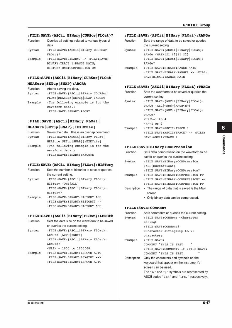
6-47IM 701610-17E
Co
mm
and
s
6
6.10 FILE Group
:FILE:SAVE:ASCii|BINary|CURSor|FLOat?Function Queries all settings related to various types of
data.
Syntax :FILE:SAVE:ASCii|BINary|COURSor|
FLOat?
Example :FILE:SAVE:BINARY? -> :FILE:SAVE:
BINARY:TRACE 1;RANGE MAIN;
HISTORY ONE;COMPRESSION ON
:FILE:SAVE:ASCii|BINary|CURSor|FLOat|
MEASure|SETup|SNAP:ABORtFunction Aborts saving the data.
Syntax :FILE:SAVE:ASCii|BINary|COURSor|
FLOat|MEASure|SETup|SNAP:ABORt
Example (The following example is for the
waveform data.)
:FILE:SAVE:BINARY:ABORT
:FILE:SAVE:ASCii|BINary|FLOat|
MEASure|SETup|SNAP[:EXECute]Function Saves the data. This is an overlap command.
Syntax :FILE:SAVE:ASCii|BINary|FLOat|
MEASure|SETup|SNAP[:EXECute]
Example (The following example is for the
waveform data.)
:FILE:SAVE:BINARY:EXECUTE
:FILE:SAVE:ASCii|BINary|FLOat:HISToryFunction Sets the number of histories to save or queries
the current setting.
Syntax :FILE:SAVE:ASCii|BINary|FLOat:
HISTory ONE|ALL
:FILE:SAVE:ASCii|BINary|FLOat:
HISTory?
Example :FILE:SAVE:BINARY:HISTORY ALL
:FILE:SAVE:BINARY:HISTORY? ->
:FILE:SAVE:BINARY:HISTORY ALL
:FILE:SAVE:ASCii|BINary|FLOat:LENGthFunction Sets the data size on the waveform to be saved
or queries the current setting.
Syntax :FILE:SAVE:ASCii|BINary|FLOat:
LENGth AUTO|<NRf>
:FILE:SAVE:ASCii|BINary|FLOat:
LENGth?
<NRf> = 1000 to 1000000
Example :FILE:SAVE:BINARY:LENGTH AUTO
:FILE:SAVE:BINARY:LENGTH? -->
:FILE:SAVE:BINARY:LENGTH AUTO
:FILE:SAVE:ASCii|BINary|FLOat:RANGeFunction Sets the range of data to be saved or queries
the current setting.
Syntax :FILE:SAVE:ASCii|BINary|FLOat:
RANGe MAIN|Z1|Z2|Z1_Z2
:FILE:SAVE:ASCii|BINary|FLOat:
RANGe?
Example :FILE:SAVE:BINARY:RANGE MAIN
:FILE:SAVE:BINARY:RANGE? -> :FILE:
SAVE:BINARY:RANGE MAIN
:FILE:SAVE:ASCii|BINary|FLOat:TRACeFunction Sets the waveform to be saved or queries the
current setting.
Syntax :FILE:SAVE:ASCii|BINary|FLOat:
TRACe ALL|<NRf>|MATH<x>
:FILE:SAVE:ASCii|BINary|FLOat:
TRACe?
<NRf>=1 to 4
<x>=1 or 2
Example :FILE:SAVE:ASCII:TRACE 1
:FILE:SAVE:ASCII:TRACE? -> :FILE:
SAVE:ASCII:TRACE 1
:FILE:SAVE:BINary:COMPressionFunction Sets data compression on the waveform to be
saved or queries the current setting.
Syntax :FILE:SAVE:BINary:COMPression
<PP|DECimation>
:FILE:SAVE:BINary:COMPression?
Example :FILE:SAVE:BINARY:COMPRESSION PP
:FILE:SAVE:BINARY:COMPRESSION? ->
:FILE:SAVE:BINARY:COMPRESSION PP
Description • The range of data that is saved is the Main
screen.
• Only binary data can be compressed.
:FILE:SAVE:COMMentFunction Sets comments or queries the current setting.
Syntax :FILE:SAVE:COMMent <Character
string>
:FILE:SAVE:COMMent?
<Character string>=Up to 25
characters
Example :FILE:SAVE:
COMMENT "THIS IS TEST. "
:FILE:SAVE:COMMENT? -> :FILE:SAVE:
COMMENT "THIS IS TEST. "
Description Only the characters and symbols on the
keyboard that appear on the instrument's
screen can be used.
The "Ω" and "µ" symbols are represented by
ASCII codes "1EH" and "1FH," respectively.
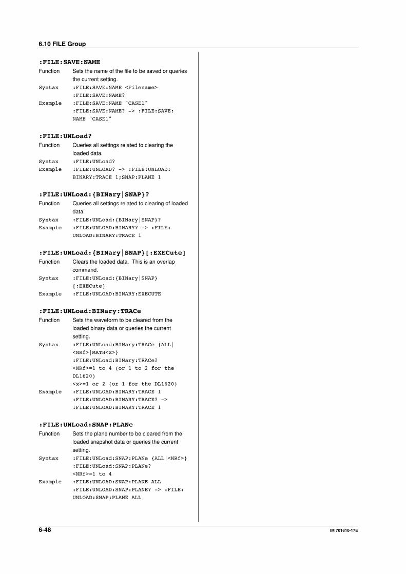
6-48 IM 701610-17E
:FILE:SAVE:NAMEFunction Sets the name of the file to be saved or queries
the current setting.
Syntax :FILE:SAVE:NAME <Filename>
:FILE:SAVE:NAME?
Example :FILE:SAVE:NAME "CASE1"
:FILE:SAVE:NAME? -> :FILE:SAVE:
NAME "CASE1"
:FILE:UNLoad?Function Queries all settings related to clearing the
loaded data.
Syntax :FILE:UNLoad?
Example :FILE:UNLOAD? -> :FILE:UNLOAD:
BINARY:TRACE 1;SNAP:PLANE 1
:FILE:UNLoad:BINary|SNAP?Function Queries all settings related to clearing of loaded
data.
Syntax :FILE:UNLoad:BINary|SNAP?
Example :FILE:UNLOAD:BINARY? -> :FILE:
UNLOAD:BINARY:TRACE 1
:FILE:UNLoad:BINary|SNAP[:EXECute]Function Clears the loaded data. This is an overlap
command.
Syntax :FILE:UNLoad:BINary|SNAP
[:EXECute]
Example :FILE:UNLOAD:BINARY:EXECUTE
:FILE:UNLoad:BINary:TRACeFunction Sets the waveform to be cleared from the
loaded binary data or queries the current
setting.
Syntax :FILE:UNLoad:BINary:TRACe ALL|
<NRf>|MATH<x>
:FILE:UNLoad:BINary:TRACe?
<NRf>=1 to 4 (or 1 to 2 for the
DL1620)
<x>=1 or 2 (or 1 for the DL1620)
Example :FILE:UNLOAD:BINARY:TRACE 1
:FILE:UNLOAD:BINARY:TRACE? ->
:FILE:UNLOAD:BINARY:TRACE 1
:FILE:UNLoad:SNAP:PLANeFunction Sets the plane number to be cleared from the
loaded snapshot data or queries the current
setting.
Syntax :FILE:UNLoad:SNAP:PLANe ALL|<NRf>
:FILE:UNLoad:SNAP:PLANe?
<NRf>=1 to 4
Example :FILE:UNLOAD:SNAP:PLANE ALL
:FILE:UNLOAD:SNAP:PLANE? -> :FILE:
UNLOAD:SNAP:PLANE ALL
6.10 FILE Group
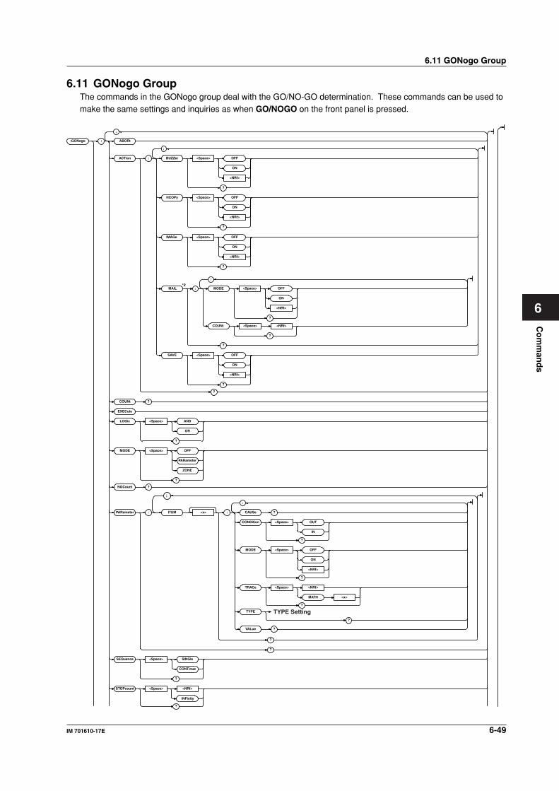
Co
mm
and
s
6-49IM 701610-17E
6
6.11 GONogo GroupThe commands in the GONogo group deal with the GO/NO-GO determination. These commands can be used tomake the same settings and inquiries as when GO/NOGO on the front panel is pressed.
:GONogo : ABORt
ACTion : BUZZer <Space> OFF
ON
<NRf>
?
HCOPy <Space> OFF
ON
<NRf>
?
?
MAIL MODE
SAVE <Space> OFF
ON
<NRf>
?
?
COUNt ?
EXECute
LOGic <Space> AND
OR
?
MODE <Space> OFF
PARameter
ZONE
?
NGCount ?
PARameter : ITEM <x> : CAUSe ?
CONDition <Space> OUT
IN
?
MODE <Space> OFF
ON
<NRf>
?
TRACe <Space> <NRf>
MATH <x>
?
TYPE
;
;
;
;
;
VALue ?
?
?
;
SEQuence <Space> SINGle
CONTinue
?
STOPcount <Space> <NRf>
?
INFinity
TYPE Setting?
<Space> <NRf>COUNt
?
IMAGe <Space> OFF
ON
<NRf>
?
<Space> OFF
ON
<NRf>
?
*2
6.11 GONogo Group
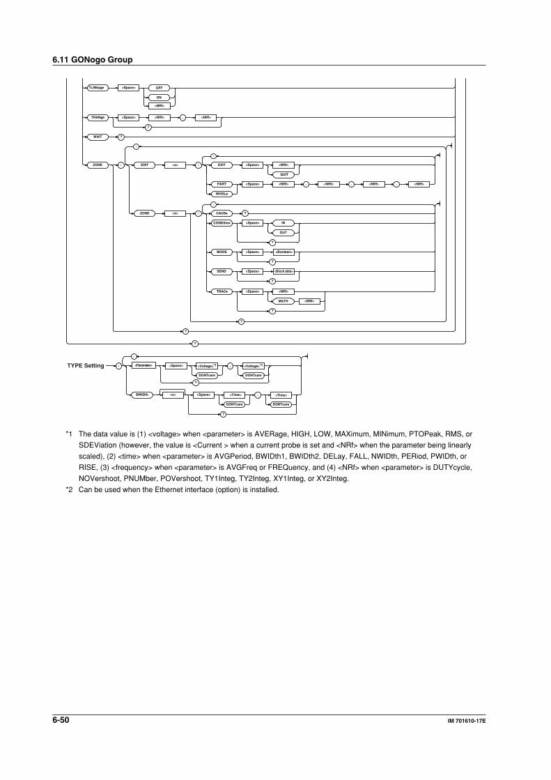
6-50 IM 701610-17E
6.11 GONogo Group
;
;
?
,
?
: <Parameter> <Space> *1 *1<Voltage> ,
DONTcareDONTcare
?
BWIDth <x> <Space> <Time> ,
DONTcareDONTcare
?
<Voltage>
<Time>
;
TYPE Setting
ZONE : EDIT <x> EXIT <Space>
QUIT
: <NRf>
PART
WHOLe
<Space> <NRf>
<NRf>
<NRf>
,<NRf> ,<NRf> <NRf>
?
;
?
ZONE <x> CAUSe:
CONDition <Space>
OUT
IN
?
TRACe <Space>
MATH
?
MODE <Space> <Boolean>
?
SEND <Space> <Block data>
?
TRANg e <Space> <NRf>
<NRf>
, <NRf>
?
TLINkage <Space>
ON
OFF
WAIT ?
*1 The data value is (1) <voltage> when <parameter> is AVERage, HIGH, LOW, MAXimum, MINimum, PTOPeak, RMS, or
SDEViation (however, the value is <Current > when a current probe is set and <NRf> when the parameter being linearly
scaled), (2) <time> when <parameter> is AVGPeriod, BWIDth1, BWIDth2, DELay, FALL, NWIDth, PERiod, PWIDth, or
RISE, (3) <frequency> when <parameter> is AVGFreq or FREQuency, and (4) <NRf> when <parameter> is DUTYcycle,
NOVershoot, PNUMber, POVershoot, TY1Integ, TY2Integ, XY1Integ, or XY2Integ.
*2 Can be used when the Ethernet interface (option) is installed.
6-51IM 701610-17E
Co
mm
and
s
6
:GONogo?Function Queries all settings related to GO/NO-GO
determination.
Syntax :GONogo?
Example :GONOGO? -> :GONOGO:MODE OFF;
PARAMETER:ITEM1:MODE 0;TRACE 1;
TYPE:MAXIMUM DONTCARE,DONTCARE;:
GONOGO:PARAMETER:ITEM1:
CONDITION OUT;:GONOGO:PARAMETER:
ITEM2:MODE 0;TRACE 1;TYPE:
MINIMUM DONTCARE,DONTCARE;:GONOGO:
PARAMETER:ITEM2:CONDITION OUT;:
GONOGO:PARAMETER:ITEM3:MODE 0;
TRACE 1;TYPE:RMS DONTCARE,
DONTCARE;:GONOGO:PARAMETER:ITEM3:
CONDITION OUT;:GONOGO:PARAMETER:
ITEM4:MODE 0;TRACE 1;TYPE:
AVERAGE DONTCARE,DONTCARE;
HIGH DONTCARE,DONTCARE;:GONOGO:
PARAMETER:ITEM4:CONDITION OUT;:
GONOGO:ZONE:ZONE1:TRACE 1;MODE 0;
CONDITION OUT;:GONOGO:ZONE:ZONE2:
TRACE 2;MODE 0;CONDITION OUT;:
GONOGO:ZONE:ZONE3:TRACE 3;MODE 0;
CONDITION OUT;:GONOGO:ZONE:ZONE4:
TRACE 4;MODE 0;CONDITION OUT;:
GONOGO:ZONE:ZONE5:TRACE MATH1;
MODE 0;CONDITION OUT;:GONOGO:ZONE:
ZONE6:TRACE MATH2;MODE 0;
CONDITION OUT;:GONOGO:LOGIC AND;
SEQUENCE SINGLE;STOPCOUNT INFINITE;
ACTION:BUZZER 0;SAVE 0;IMAGE 0;
HCOPY 0;MAIL:MODE 0;COUNT 100;:
GONOGO:TLINKAGE 0;
TRANGE -5.0000000,5.0000000
:GONogo:ABORtFunction Aborts GO/NO-GO determination.
Syntax :GONogo:ABORt
Example :GONOGO:ABORT
:GONogo:ACTion?Function Queries all settings related to the action to be
performed when the result of the determination
is NO-GO and also the determination criteria.
Syntax :GONogo:ACTion?
Example :GONOGO:ACTION? -> :GONOGO:ACTION:
BUZZER 0;IMAGE 0;HCOPY 0;SAVE 0
:GONogo:ACTion:BUZZerFunction Sets whether or not to sound an alarm when
the determination is NO-GO or queries the
current setting.
Syntax :GONogo:ACTion:BUZZer <Boolean>
:GONogo:ACTion:BUZZer?
Example :GONOGO:ACTION:BUZZER OFF
:GONOGO:ACTION:BUZZER? -> :GONOGO:
ACTION:BUZZER 0
:GONogo:ACTion:HCOPy (Hard COPY)Function Sets whether or not to make a hard copy to the
built-in printer (option) or the external printer
when the determination results in NO-GO or
queries the current setting.
Syntax :GONogo:ACTion:HCOPy <Boolean>
:GONogo:ACTion:HCOPy?
Example :GONOGO:ACTION:HCOPY OFF
:GONOGO:ACTION:HCOPY? -> :GONOGO:
ACTION:HCOPY 0
:GONogo:ACTion:IMAGeFunction Sets whether or not to save the screen image to
the external storage medium for NO-GO
determination or queries the current setting.
Syntax :GONogo:ACTion:IMAGe <Boolean>
:GONogo:ACTion:IMAGe?
Example :GONOGO:ACTION:IMAGE OFF
:GONOGO:ACTION:IMAGE? -> :GONOGO:
ACTION:IMAGE 0
:GONogo:ACTion:MAIL?Function Queries the all settings for an e-mail to be sent
when the determination is NO-GO.
Syntax :GONogo:ACTion:MAIL?
Example :GONOGO:ACTION:MAIL? -> :GONOGO:
ACTION:MAIL:MODE 1;COUNT 100
Description Can be used when the Ethernet interface
(option) is installed.
:GONogo:ACTion:MAIL:COUNtFunction Sets/queries the maximum number of e-mail to
be sent when the determination is NO-GO.
Syntax :GONogo:ACTion:MAIL:COUNt <NRf>
:GONogo:ACTion:MAIL:COUNt?
<NRf>=1 to 1000
Example :GONOGO:ACTION:MAIL:COUNT 100
:GONOGO:ACTION:MAIL:COUNT? ->
:GONOGO:ACTION:MAIL:COUNT 100
Description Can be used when the Ethernet interface
(option) is installed.
:GONogo:ACTion:MAIL:MODEFunction Sets/queries whether an e-mail report is sent
when the determination is NO-GO.
Syntax :GONogo:ACTion:MAIL:MODE <Boolean>
:GONogo:ACTion:MAIL:MODE?
Example :GONOGO:ACTION:MAIL:MODE OFF
:GONOGO:ACTION:MAIL:MODE? ->
:GONOGO:ACTION:MAIL:MODE 0
Description Can be used when the Ethernet interface
(option) is installed.
6.11 GONogo Group
6-52 IM 701610-17E
6.11 GONogo Group
:GONogo:ACTion:SAVEFunction Sets whether or not to save the NO-GO result
to the medium or queries the current setting.
Syntax :GONogo:ACTion:SAVE <Boolean>
:GONogo:ACTion:SAVE?
Example :GONOGO:ACTION:SAVE OFF
:GONOGO:ACTION:SAVE? -> :GONOGO:
ACTION:SAVE 0
Description Use the ":FILE:DIRECTORY:DRIVE"
command to set or query the medium type.
:GONogo:COUNt?Function Queries the actual number of times the GO/NO-
GO determination has been performed.
Syntax :GONogo:COUNt?
Example :GONOGO:COUNT? -> :GONOGO:COUNT 100
:GONogo:EXECuteFunction Executes GO/NO-GO determination. This is an
overlap command.
Syntax :GONogo:EXECute
Example :GONOGO:EXECUTE
:GONogo:LOGicFunction Sets the GO/NO-GO determination logic or
queries the current setting.
Syntax :GONogo:LOGic AND|OR
:GONogo:LOGic?
Example :GONOGO:LOGIC AND
:GONOGO:LOGIC? -> :GONOGO:LOGIC AND
:GONogo:MODEFunction Sets the GO/NO-GO determination type or
queries the current setting.
Syntax :GONogo:MODE OFF|PARameter|ZONE
:GONogo:MODE?
Example :GONOGO:MODE PARAMETER
:GONOGO:MODE? -> :GONOGO:
MODE PARAMETER
:GONogo:NGCount?Function Queries the number of NO-GO results.
Syntax :GONogo:NGCount?
Example :GONOGO:NGCOUNT? -> :GONOGO:
NGCOUNT 5
:GONogo:PARameter?Function Queries all settings related to the parameter
determination.
Syntax :GONogo:PARameter?
Example :GONOGO:PARAMETER? -> :GONOGO:
PARAMETER:ITEM1:MODE 0;TRACE 1;
TYPE:MAXIMUM 1.0000E+00,
-1.0000E+00;:GONOGO:PARAMETER:
ITEM1:CONDITION OUT;:GONOGO:
PARAMETER:ITEM2:MODE 0;TRACE 1;
TYPE:MINIMUM 1.0000E+00,
-1.0000E+00;:GONOGO:PARAMETER:
ITEM2:CONDITION OUT;:GONOGO:
PARAMETER:ITEM3:MODE 0;TRACE 1;
TYPE:RMS 1.0000E+00,-1.0000E+00;:
GONOGO:PARAMETER:ITEM3:
CONDITION OUT;:GONOGO:PARAMETER:
ITEM4:MODE 0;TRACE 1;TYPE:
AVERAGE 1.0000E+00,-1.0000E+00;:
GONOGO:PARAMETER:ITEM4:
CONDITION OUT
:GONogo:PARameter:ITEM<x>?Function Queries all settings related to waveform
parameters.
Syntax :GONogo:PARameter:ITEM<x>?
<x>=1 to 4
Example :GONOGO:PARAMETER:ITEM1? ->
:GONOGO:PARAMETER:ITEM1:MODE 0;
TRACE 1;TYPE:MAXIMUM 1.0000E+00,
-1.0000E+00;:GONOGO:PARAMETER:
ITEM1:CONDITION OUT
:GONogo:PARameter:ITEM<x>:CAUSe?Function Queries whether or not the waveform
parameter is the cause of the NO-GO result.
Syntax GONogo:PARameter:ITEM<x>:CAUSe?
<x>=1 to 4
Example :GONOGO:PARAMETER:ITEM1:CAUSE? ->
:GONOGO:PARAMETER:ITEM1:CAUSE 1
Description The query returns a "1" if the parameter is the
cause of the NO-GO result or a "0" if it is not.
:GONogo:PARameter:ITEM<x>:CONDitionFunction Sets the criteria for each waveform parameter
or queries the current setting.
Syntax :GONogo:PARameter:ITEM<x>:
CONDition IN|OUT
:GONogo:PARameter:ITEM<x>:
CONDition?
<x>=1 to 4
Example :GONOGO:PARAMETER:ITEM1:CONDITION
OUT
:GONOGO:PARAMETER:ITEM1:CONDITION?
-> :GONOGO:PARAMETER:ITEM1:
CONDITION OUT
6-53IM 701610-17E
Co
mm
and
s
6
:GONogo:PARameter:ITEM<x>:MODEFunction Turns the waveform parameter ON/OFF or
queries the current setting.
Syntax :GONogo:PARameter:ITEM<x>:
MODE <Boolean>
:GONogo:PARameter:ITEM<x>:MODE?
Example :GONOGO:PARAMETER:ITEM<x>:MODE OFF
:GONOGO:PARAMETER:ITEM<x>:MODE? ->
:GONOGO:PARAMETER:ITEM<x>:MODE 0
:GONogo:PARameter:ITEM<x>:TRACeFunction Sets the waveform on which to use the
waveform parameter or queries the current
setting.
Syntax :GONogo:PARameter:ITEM<x>:
TRACe <NRf>|MATH<x>
:GONogo:PARameter:ITEM<x>:TRACe?
The <x> in ITEM<x>=1 to 4
<NRf>=1 to 4(or 1 to 2 for the
DL1620)
The <x> in MATH<x>=1 or 2(or 1 to 2
for the DL1620)
Example :GONOGO:PARAMETER:ITEM1:TRACE 1
:GONOGO:PARAMETER:ITEM1:TRACE? ->
:GONOGO:PARAMETER:ITEM1:TRACE 1
:GONogo:PARameter:ITEM<x>:TYPE?Function Queries the waveform parameter and the upper
and lower limits.
Syntax :GONogo:PARameter:ITEM<x>:TYPE?
<x>=1 to 4
Example :GONOGO:PARAMETER:ITEM1:TYPE? ->
:GONOGO:PARAMETER:ITEM1:TYPE:
PTOPEAK 2.000E+00,1.000E+00
:GONogo:PARameter:ITEM<x>:TYPE:
<parameter>Function Sets the upper and lower limits of each
waveform parameter or queries the current
setting.
Syntax :GONogo:PARameter:ITEM<x>:TYPE:
<parameter> <voltage|DONTcare>,
<voltage|DONTcare>|
<current|DONTcare>,
<current|DONTcare>|
<time|DONTcare>,
<time|DONTcare>|
<frequency|DONTcare>,
<frequency|DONTcare>|<<NRf>|
DONTcare>,<<NRf>|DONTcare>
:GONogo:PARameter:ITEM<x>:TYPE:
<parameter>?
<parameter>=AVERage|AVGFreq|
AVGPeriod|BWIDth1|
BWIDth2|DELay|
DUTYcycle|FALL|
FREQuency|HIGH|LOW|
MAXimum|MINimum|
NOVershoot|NWIDth|
PERiod|PNUMber|
POVershoot|PTOPeak|
PWIDth|RISE|RMS|
SDEViation|TY1Integ|
TY2Integ|XY1Integ|
XY2Integ
<voltage>,<time>,<frequency>,<current>,
<NRf>=See the IM701610-01E User's
Manual.
Example :GONOGO:PARAMETER:ITEM1:TYPE:
AVERAGE 100mV,-100mV
:GONOGO:PARAMETER:ITEM1:TYPE:
AVERAGE? -> :GONOGO:PARAMETER:
ITEM1:TYPE:AVERAGE 100.0E-03,
-100.0E-03
Description Only the parameters that are set using this
command can be queried.
:GONogo:PARameter:ITEM<x>:VALue?Function Queries the measured value of each waveform
parameter.
Syntax :GONogo:PARameter:ITEM<x>:VALue?
<x>=1 to 4
Example :GONOGO:PARAMETER:ITEM1:VALUE? ->
:GONOGO:PARAMETER:ITEM1:
VALUE 1.98E-03
Description If the measurement is not possible (the mode is
OFF, for example), "NAN(Not A Number)" is
returned.
6.11 GONogo Group

6-54 IM 701610-17E
6.11 GONogo Group
:GONogo:SEQuenceFunction Selects single or continuous action or queries
the current setting.
Syntax :GONogo:SEQuence CONTinuous|
SINGle
:GONogo:SEQuence?
Example :GONOGO:SEQUENCE SINGLE
:GONOGO:SEQUENCE? -> :GONOGO:
SEQUENCE SINGLE
:GONogo:STOPcountFunction Sets the number of waveform acquisitions on
which to perform GO/NO-GO determination or
queries the current setting.
Syntax :GONogo:STOPcount <NRf>|INFinity
:GONogo:STOPcount?
<NRf>=1 to 65536
Example :GONOGO:PARAMETER:STOPCOUNT 10
:GONOGO:PARAMETER:STOPCOUNT? ->
:GONOGO:STOPCOUNT 10
:GONogo:TLINkageFunction Turns ON/OFF the linked movement of the
determination range cursor of the GO/NO-GO
determination.
Syntax :GONogo:TLINkage <Boolean>
:GONogo:TLINkage?
Example :GONOGO:TLINKAGE ON
:GONOGO:TLINKAGE? ->GONOGO:
TLINKAGE 1
:GONogo:TRANgeFunction Sets the range over which to perform GO/NO-
GO determination or queries the current setting.
Syntax :GONogo:TRANge <NRf>,<NRf>
:GONogo:TRANge?
<NRf>=-5.00 to 5.00 (10 div/
displayed record length steps)
Example :GONOGO:TRANGE -5.00,5.00
:GONOGO:TRANGE? -> :GONOGO:
TRANGE -5.00,5.00
:GONogo:WAIT?Function Waits for the GO/NO-GO determination to
complete with a timeout.
Syntax :GONogo:WAIT? <NRf>
<NRf>=0 to 864000 (in units of 100 ms)
Example (Set the timeout to 5 s.)
:GONOGO:WAIT? 50 -> :GONOGO:WAIT 0
Description Returns "1" if it times out, "0" if it completes
before timing out.
:GONogo:ZONE?Function Queries all settings related to zone
determination.
Syntax :GONogo:ZONE?
Example :GONOGO:ZONE? -> :GONOGO:ZONE:ZONE1:
TRACE 1;MODE 0;CONDITION OUT;:
GONOGO:ZONE:ZONE2:TRACE 2;MODE 0;
CONDITION OUT;:GONOGO:ZONE:ZONE3:
TRACE 3;MODE 0;CONDITION OUT;:
GONOGO:ZONE:ZONE4:TRACE 4;MODE 0;
CONDITION OUT;:GONOGO:ZONE:ZONE5:
TRACE MATH1;MODE 0;CONDITION OUT;:
GONOGO:ZONE:ZONE6:TRACE MATH2;
MODE 0;CONDITION OUT
:GONogo:ZONE:EDIT<x>:EXITFunction Exits from the edit menu of the zone for zone
determination.
Syntax :GONogo:ZONE:EDIT<x>:EXIT <NRf>|
QUIT
<X>= 1 to 12 (1 to 4 are traces; 5
and 6 is MATH1 and 2; 7 to 12 are
determination zones 1 to 6.)
On the DL1620, <X>=1, 2, 5, 7, 8,
or 9 (1 to 2 are traces; 5 is MATH1
; 7 to 9 are determination zones 1
to 3.)
<NRf>=1 to 6 (destination zone No.
for saving the zone being edited)
On the DL1620, <NRf>=1 to 3
Example :GONOGO:ZONE:EDIT1:EXIT 1
Description This command must be issued to keep the
zones specified using ":GONogo:ZONE:
EDIT<x>:PART|WHOLe."
An error occurs if this command is issued when
the zone is not being edited.
:GONogo:ZONE:EDIT<x>:PARTFunction Edits a portion of the zone for zone
determination.
Syntax :GONogo:ZONE:EDIT<x>:PART <NRf>,
<NRf>,<NRf>,<NRf>
<X>= 1 to 12 (1 to 4 are traces; 5
and 6 is MATH1 and 2; 7 to 12 are
determination zones 1 to 6.)
On the DL1620, <X>=1, 2, 5, 7, 8,
or 9 (1 to 2 are traces; 5 is MATH1
; 7 to 9 are determination zones 1
to 3.)
<NRf>=-5.00 to 5.00 (div, 0.01
steps: T1 and T2 cursor)
-8.00 to 8.00 (div, 0.05 steps: up
and down)
(in the order T1, T2, ↑, and ↓)Example :GONOGO:ZONE:EDIT1:PART -
2.50,2.50,1.00,
1.00
6-55IM 701610-17E
Co
mm
and
s
6
Description When you finish editing, you must exit the edit
mode using the ":GONogo:ZONE:
EDIT<x>:EXIT" command to keep the new
zone.
:GONogo:ZONE:EDIT<x>:WHOLeFunction Edits the zone for zone determination.
Syntax :GONogo:ZONE:EDIT<x>:WHOLe <NRf>,
<NRf>,<NRf>,<NRf>
<X>= 1 to 12 (1 to 4 are traces; 5
and 6 is MATH1 and 2; 7 to 12 are
determination zones 1 to 6.)
On the DL1620, <X>=1, 2, 5, 7, 8,
or 9 (1 to 2 are traces; 5 is MATH1
; 7 to 9 are determination zones 1
to 3.)
<NRf>=0 to 5.00 (div, 0.01 steps:
left and right)
0 to 8.00 (div, 0.05 steps: up and
down)
(in the order <-, ->, ↑, and ↓)Example :GONOGO:ZONE:EDIT1:WHOLE -2.50,
2.50,1.00,1.00
Description When you finish editing, you must exit the edit
mode using the ":GONogo:ZONE:
EDIT<x>:EXIT" command to keep the new
zone.
:GONogo:ZONE:ZONE<x>?Function Queries all settings related to zone
determination of the specified zone.
Syntax :GONogo:ZONE:ZONE<x>?
<x>=1 to 6 (or 1 to 3 for the
DL1620)
Example :GONOGO:ZONE:ZONE1? -> :GONOGO:
ZONE:ZONE1:TRACE 1;MODE 0;
CONDITION OUT
:GONogo:ZONE:ZONE<x>:CAUSe?Function Queries whether or not the specified zone for
zone determination is the cause of the NO-GO
result.
Syntax :GONogo:ZONE:ZONE<x>:CAUSe?
<x>=1 to 6 (or 1 to 3 for the
DL1620)
Example :GONOGO:ZONE:ZONE1:CAUSE? ->
:GONOGO:ZONE:ZONE1:CAUSE 1
Description The query returns a "1" if the zone is the
cause of the NO-GO result or a "0" if it is not.
:GONogo:ZONE:ZONE<x>:CONDitionFunction Sets the criteria for the zone for zone
determination or queries the current setting.
Syntax :GONogo:ZONE:ZONE<x>:CONDition IN|
OUT
:GONogo:ZONE:ZONE<x>:CONDition?
<x>=1 to 6 (or 1 to 3 for the
DL1620)
Example :GONOGO:ZONE:ZONE1:CONDITION IN
:GONOGO:ZONE:ZONE1:CONDITION? ->
:GONOGO:ZONE:ZONE1:CONDITION IN
:GONogo:ZONE:ZONE<x>:MODEFunction Turns ON/OFF the determination of the zone or
queries the current setting.
Syntax :GONogo:ZONE:ZONE<x>:
MODE <Boolean>
:GONogo:ZONE:ZONE<x>:MODE?
<x>=1 to 6 (or 1 to 3 for the
DL1620)
Example :GONOGO:ZONE:ZONE1:MODE ON
:GONOGO:ZONE:ZONE1:MODE? ->
:GONOGO:ZONE:ZONE1:MODE 1
:GONogo:ZONE:ZONE<x>:SENDFunction Sets the zone data specified for the
determination zone or queries the current
setting.
Syntax :GONogo:ZONE:ZONE<x>:SEND #6004028
(data string)
:GONnogo:ZONE:ZONE<x>:SEND?
<x>=1 to 6 (or 1 to 3 for the
DL1620)
Example :GONOGO:ZONE:ZONE1:SEND #6004028
(data string)
:GONOGO:ZONE:ZONE1:SEND? ->
:GONOGO:ZONE:ZONE1:
SEND #6004028(data string)
Description • The (data string) consists of zone data of
length 4028 bytes.
• Zone data consist of 8-bit data (0 to 255).
This data string may contain ASCII codes
"0AH" or "00H" that stand for "NL."
Hence, care must be taken when
programming the controller.
• This command is used to save the zone data
to the PC and set the data as zone data on
the instrument.
• When this command is used to set the zone
data to the instrument to perform the
determination, issue the ":GONogo:ZONE:
ZONE<x>:MODE ON" command afterwards.
:GONogo:ZONE:ZONE<x>:TRACeFunction Sets the target trace for the zone for zone
determination or queries the current setting.
Syntax :GONogo:ZONE:ZONE<x>:TRACe <NRf>|
MATH<y>
:GONogo:ZONE:ZONE<x>:TRACe?
<NRf>=1 to 4 (or 1 to 2 for the
DL1620)
<x>=1 to 6 (or 1 to 3 for the
DL1620)
<y>=1,2 (or 1 for the DL1620)
Example :GONOGO:ZONE:ZONE1:TRACE 1
:GONOGO:ZONE:ZONE1:TRACE ->
:GONOGO:ZONE:ZONE1:TRACE 1
6.11 GONogo Group
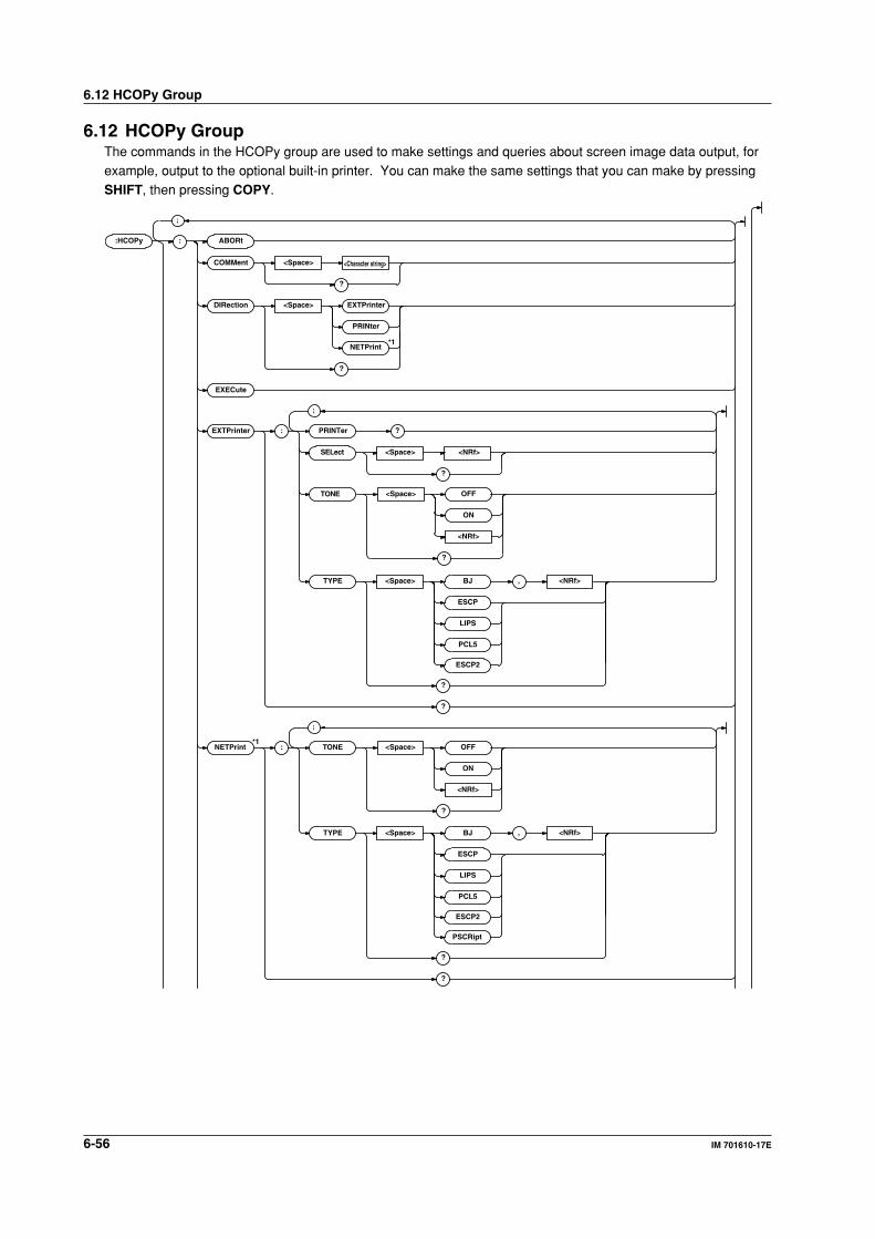
6-56 IM 701610-17E
6.12 HCOPy Group
6.12 HCOPy GroupThe commands in the HCOPy group are used to make settings and queries about screen image data output, forexample, output to the optional built-in printer. You can make the same settings that you can make by pressingSHIFT, then pressing COPY.
:HCOPy : ABORt
COMMent <Space> <Character string>
?
DIRection <Space> EXTPrinter
PRINter
NETPrint*1
?
?
EXECute
;
EXTPrinter : PRINTer
SELect <Space> <NRf>
?
TYPE
TONE
<Space> BJ
ESCP
LIPS
PCL5
ESCP2
?
?
;
, <NRf>
NETPrint*1
: TONE
TYPE <Space> BJ
ESCP
LIPS
PCL5
ESCP2
?
PSCRipt
?
;
, <NRf>
<Space> OFF
ON
<NRf>
?
<Space> OFF
ON
<NRf>
?
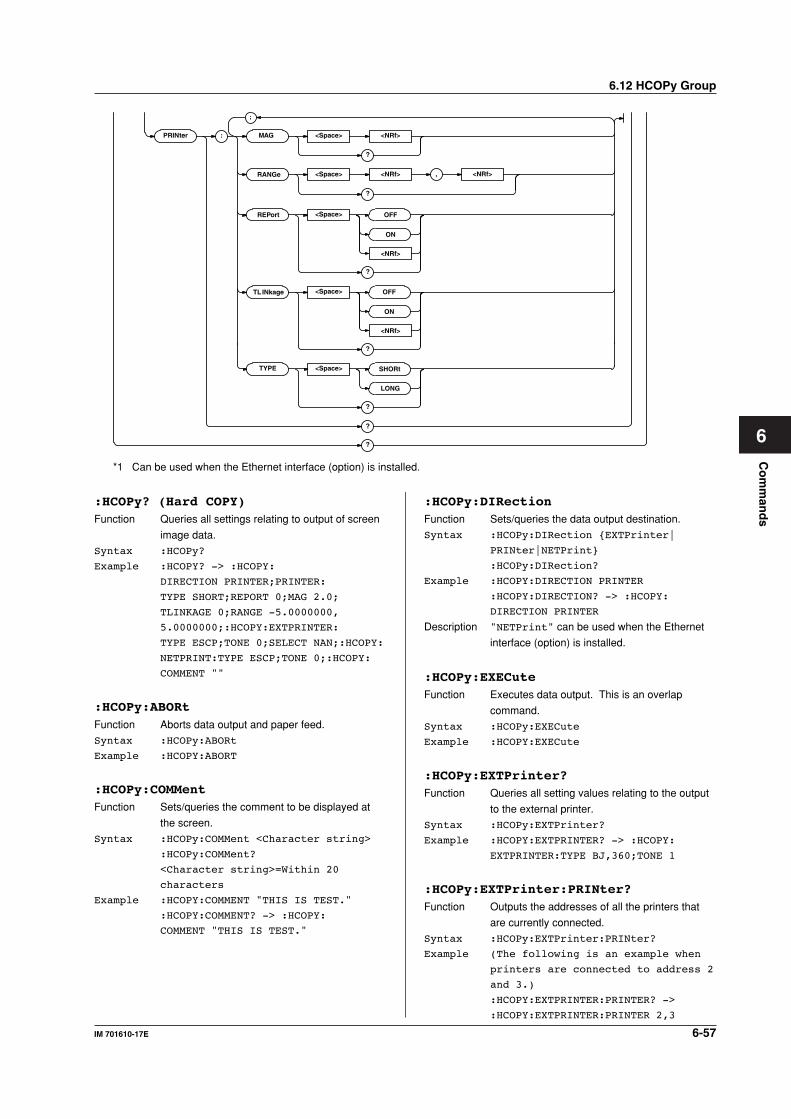
6-57IM 701610-17E
Co
mm
and
s
6
PRINter
RANGe
REPort
: MAG <Space> <NRf>
?
<Space> <NRf>
?
<Space>
<NRf>
OFF
ON
?
<Space>
<NRf>
OFF
ON
?
;
, <NRf>
TYPE <Space> SHORt
LONG
?
?
?
TLINkage
*1 Can be used when the Ethernet interface (option) is installed.
:HCOPy? (Hard COPY)Function Queries all settings relating to output of screen
image data.
Syntax :HCOPy?
Example :HCOPY? -> :HCOPY:
DIRECTION PRINTER;PRINTER:
TYPE SHORT;REPORT 0;MAG 2.0;
TLINKAGE 0;RANGE -5.0000000,
5.0000000;:HCOPY:EXTPRINTER:
TYPE ESCP;TONE 0;SELECT NAN;:HCOPY:
NETPRINT:TYPE ESCP;TONE 0;:HCOPY:
COMMENT ""
:HCOPy:ABORtFunction Aborts data output and paper feed.
Syntax :HCOPy:ABORt
Example :HCOPY:ABORT
:HCOPy:COMMentFunction Sets/queries the comment to be displayed at
the screen.
Syntax :HCOPy:COMMent <Character string>
:HCOPy:COMMent?
<Character string>=Within 20
characters
Example :HCOPY:COMMENT "THIS IS TEST."
:HCOPY:COMMENT? -> :HCOPY:
COMMENT "THIS IS TEST."
:HCOPy:DIRectionFunction Sets/queries the data output destination.
Syntax :HCOPy:DIRection EXTPrinter|
PRINter|NETPrint
:HCOPy:DIRection?
Example :HCOPY:DIRECTION PRINTER
:HCOPY:DIRECTION? -> :HCOPY:
DIRECTION PRINTER
Description "NETPrint" can be used when the Ethernet
interface (option) is installed.
:HCOPy:EXECuteFunction Executes data output. This is an overlap
command.
Syntax :HCOPy:EXECute
Example :HCOPY:EXECute
:HCOPy:EXTPrinter?Function Queries all setting values relating to the output
to the external printer.
Syntax :HCOPy:EXTPrinter?
Example :HCOPY:EXTPRINTER? -> :HCOPY:
EXTPRINTER:TYPE BJ,360;TONE 1
:HCOPy:EXTPrinter:PRINter?Function Outputs the addresses of all the printers that
are currently connected.
Syntax :HCOPy:EXTPrinter:PRINter?
Example (The following is an example when
printers are connected to address 2
and 3.)
:HCOPY:EXTPRINTER:PRINTER? ->
:HCOPY:EXTPRINTER:PRINTER 2,3
6.12 HCOPy Group
6-58 IM 701610-17E
6.12 HCOPy Group
:HCOPy:EXTPrinter:SELectFunction Sets the printer address or queries the current
setting.
Syntax :HCOPy:EXTPrinter:SELect <NRf>
:HCOPy:EXTPrinter:SELect?
<NRf>=1 to 127
Example :HCOPY:EXTPRINTER:SELECT 3
:HCOPY:EXTPRINTER:SELECT? ->
:HCOPY:EXTPRINTER:SELECT 3
Description If you specify an address at which no printer is
connected, an error occurs. In this case, "NAN
(Not A Number)" is returned.
:HCOPy:EXTPrinter:TONEFunction Sets/queries the half tone setting for the
external printer.
Syntax :HCOPy:EXTPrinter:TONE <Boolean>
:HCOPy:EXTPrinter:TONE?
Example :HCOPY:EXTPRINTER ON
:HCOPY:EXTPRINTER? -> :HCOPY:
EXTPRINTER TONE 1
:HCOPy:EXTPrinter:TYPEFunction Sets/queries the command type to output to the
external printer.
Syntax :HCOPy:EXTPrinter:TYPE BJ,<NRf>|
ESCP|LIPS|PCL5|ESCP2
:HCOPy:EXTPrinter:TYPE?
<NRf>=180, 300, 360 or 600 (dpi)
Example :HCOPY:EXTPRINTER:TYPE BJ,360
:HCOPY:EXTPRINTER:TYPE? -> :HCOPY:
EXTPRINTER:TYPE BJ,360
Description <NRf> is specified only when the type is set to
"BJ."
:HCOPy:NETprint?Function Queries all settings values involving output to
network printers.
Syntax :HCOPy:NETPrint?
Example :HCOPY:NETPRINT? -> :HCOPY:
NETPRINT:TYPE POSTSCRIPT;TONE 1
Description Can be used when the Ethernet interface
(option) is installed.
:HCOPy:NETprint:TONEFunction Sets/queries halftones for output to network
printers.
Syntax :HCOPy:NETPrint:TONE <Boolean>
:HCOPy:NETPrint:TONE?
Example :HCOPY:NETPRINT:TONE ON
:HCOPY:NETPRINT:TONE? -> :HCOPY:
NETPRINT:TONE 1
Description Can be used when the Ethernet interface
(option) is installed.
:HCOPy:NETprint:TYPEFunction Sets/queries command types for output to
network printers.
Syntax :HCOPy:NETPrint:TYPE BJ,<NRf>|
ESCP|LIPS|PCL5|ESCP2|PSCRipt
:HCOPy:NETPrint:TYPE?
<NRf>=180, 300, 360 or 600 (dpi)
Example :HCOPY:NETPRINT:TYPE PSCRIPT
:HCOPY:NETPRINT:TYPE? -> :HCOPY:
NETPRINT:TYPE PSCRIPT
Description <NRf> is specified only when the type is set to
"BJ." Can be used when the Ethernet
interface (option) is installed.
:HCOPy:PRINter?Function Queries all settings relating to the built-in
printer.
Syntax :HCOPy:PRINter?
Example :HCOPY:PRINTER? -> :HCOPY:PRINTER:
TYPE SHORT;REPORT 0;TLINKAGE 0;
RANGE -5.00,5.00;MAG 2
:HCOPy:PRINter:MAGFunction Sets the zoom rate to use when using the long
copy function to print to the built-in printer or
queries the current setting.
Syntax :HCOPy:PRINter:MAG <NRf>
:HCOPy:PRINter:MAG?
<NRf>=2 to 8000000 (See the
IM701610-01E User's Manual.)
Example :HCOPY:PRINTER:MAG 1
:HCOPY:PRINTER:MAG? -> :HCOPY:
PRINTER:MAG 1
:HCOPy:PRINter:RANGeFunction Sets the output range when using the long copy
function to print to the built-in printer or queries
the current setting.
Syntax :HCOPy:PRINter:
RANGe <NRf>,<NRf>
:HCOPy:PRINter:RANGe?
<NRf>=–5.00 to 5.00 (10 div/
displayed record length steps)
Example :HCOPY:PRINTER:RANGE -2.50,2.50
:HCOPY:PRINTER:RANGE? -> :HCOPY:
PRINTER:RANGE -2.50,2.50
:HCOPy:PRINter:REPortFunction Sets whether or not to output additional
information to the built-in printer or queries the
current setting.
Syntax :HCOPy:PRINter:REPort <Boolean>
:HCOPy:PRINter:REPort?
Example :HCOPY:PRINTER:REPORT ON
:HCOPY:PRINTER:REPORT? -> :HCOPY:
PRINTER:REPORT 1
6-59IM 701610-17E
Co
mm
and
s
6
:HCOPy:PRINter:TLINkageFunction Turns ON/OFF the linked movement of the
output range cursor during long copy.
Syntax :HCOPy:PRINter:TLINkage <Boolean>
:HCOPy:PRINter:TLINkage?
Example :HCOPY:PRINTER:TLINKAGE ON
:HCOPY:PRINTER:TLINKAGE -> :HCOPY:
PRINTER:TLINKAGE 1
:HCOPy:PRINter:TYPEFunction Selects short copy or long copy when printing to
the built-in printer or queries the current setting.
Syntax :HCOPy:PRINter:TYPE LONG|SHORt
:HCOPy:PRINter:TYPE?
Example :HCOPY:PRINTER:TYPE SHORT
:HCOPY:PRINTER:TYPE? -> :HCOPY:
PRINTER:TYPE SHORT
6.12 HCOPy Group
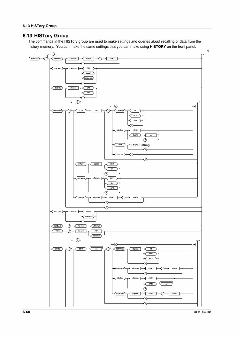
6-60 IM 701610-17E
6.13 HISTory Group
6.13 HISTory GroupThe commands in the HISTory group are used to make settings and queries about recalling of data from thehistory memory. You can make the same settings that you can make using HISTORY on the front panel.
:HISTor y : DISPlay <Space> <NRf> , <NRf>
?
<Space> OFF
ZONE
PARameter
?
DMODe
SMODe
<Space> MINimum?RECord
<Space> ONE
ALL
?
RECord <Space> <NRf>
MINimum
?
TIME ? <Space> <NRf>
MINimum
ZONE : EDIT <x> : CONDition <Space> IN
OUT
OFF
?
HORizontal <Space> <NRf> , <NRf>
?
SOURce <Space> <NRf>
MATH <x>
?
VERTical <Space> <NRf> , <NRf>
?
?
;
;
;
PARameter : ITEM <x> : CONDition IN
OUT
OFF
?
?
SOURce <NRf>
TYPE
MATH <x>
?
VALue ?
?
LOGic <Space> AND
OR
?
?
TRANge <Space> <NRf> <NRf>
?
,
;
;
TYPE Setting
<Space>
<NRf>
OFF
ON
?
TLINkage
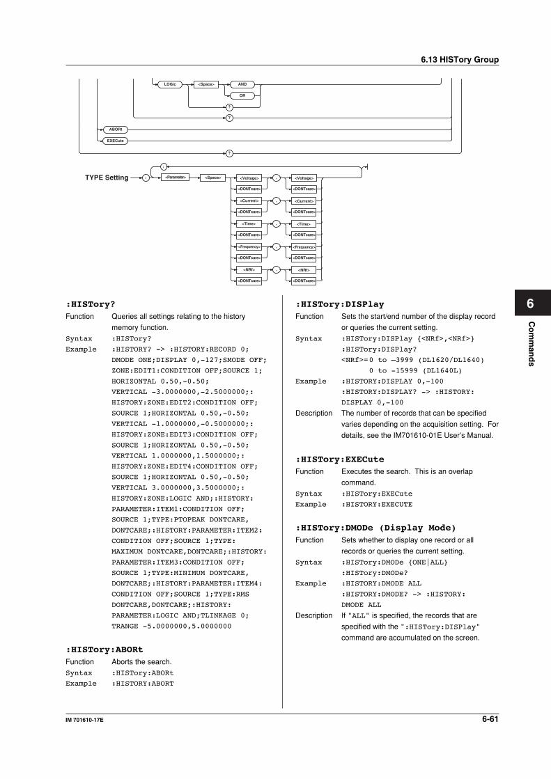
6-61IM 701610-17E
Co
mm
and
s
6
ABORt
EXECute
?
: <Parameter> <Space> <Voltage> ,
<DONTcare><DONTcare>
<Voltage>
<Time> ,
<DONTcare><DONTcare>
<Time>
<Current> ,
<DONTcare><DONTcare>
<Current>
<Frequency> ,
<DONTcare><DONTcare>
<Frequency>
<NRf> ,
<DONTcare><DONTcare>
<NRf>
TYPE Setting
;
LOGic <Space> AND
OR
?
?
:HISTory?Function Queries all settings relating to the history
memory function.
Syntax :HISTory?
Example :HISTORY? -> :HISTORY:RECORD 0;
DMODE ONE;DISPLAY 0,-127;SMODE OFF;
ZONE:EDIT1:CONDITION OFF;SOURCE 1;
HORIZONTAL 0.50,-0.50;
VERTICAL -3.0000000,-2.5000000;:
HISTORY:ZONE:EDIT2:CONDITION OFF;
SOURCE 1;HORIZONTAL 0.50,-0.50;
VERTICAL -1.0000000,-0.5000000;:
HISTORY:ZONE:EDIT3:CONDITION OFF;
SOURCE 1;HORIZONTAL 0.50,-0.50;
VERTICAL 1.0000000,1.5000000;:
HISTORY:ZONE:EDIT4:CONDITION OFF;
SOURCE 1;HORIZONTAL 0.50,-0.50;
VERTICAL 3.0000000,3.5000000;:
HISTORY:ZONE:LOGIC AND;:HISTORY:
PARAMETER:ITEM1:CONDITION OFF;
SOURCE 1;TYPE:PTOPEAK DONTCARE,
DONTCARE;:HISTORY:PARAMETER:ITEM2:
CONDITION OFF;SOURCE 1;TYPE:
MAXIMUM DONTCARE,DONTCARE;:HISTORY:
PARAMETER:ITEM3:CONDITION OFF;
SOURCE 1;TYPE:MINIMUM DONTCARE,
DONTCARE;:HISTORY:PARAMETER:ITEM4:
CONDITION OFF;SOURCE 1;TYPE:RMS
DONTCARE,DONTCARE;:HISTORY:
PARAMETER:LOGIC AND;TLINKAGE 0;
TRANGE -5.0000000,5.0000000
:HISTory:ABORtFunction Aborts the search.
Syntax :HISTory:ABORt
Example :HISTORY:ABORT
:HISTory:DISPlayFunction Sets the start/end number of the display record
or queries the current setting.
Syntax :HISTory:DISPlay <NRf>,<NRf>
:HISTory:DISPlay?
<NRf>=0 to –3999 (DL1620/DL1640)
0 to -15999 (DL1640L)
Example :HISTORY:DISPLAY 0,-100
:HISTORY:DISPLAY? -> :HISTORY:
DISPLAY 0,-100
Description The number of records that can be specified
varies depending on the acquisition setting. For
details, see the IM701610-01E User’s Manual.
:HISTory:EXECuteFunction Executes the search. This is an overlap
command.
Syntax :HISTory:EXECute
Example :HISTORY:EXECUTE
:HISTory:DMODe (Display Mode)Function Sets whether to display one record or all
records or queries the current setting.
Syntax :HISTory:DMODe ONE|ALL
:HISTory:DMODe?
Example :HISTORY:DMODE ALL
:HISTORY:DMODE? -> :HISTORY:
DMODE ALL
Description If "ALL" is specified, the records that are
specified with the ":HISTory:DISPlay"
command are accumulated on the screen.
6.13 HISTory Group
6-62 IM 701610-17E
6.13 HISTory Group
:HISTory:PARameter?Function Queries all settings related to the parameter
search.
Syntax :HISTory:PARameter?
Example :HISTORY:PARAMETER? -> :HISTORY:
PARAMETER:ITEM1:CONDITION OFF;
SOURCE 1;TYPE:PTOPEAK DONTCARE,
DONTCARE;:HISTORY:PARAMETER:ITEM2:
CONDITION OFF;SOURCE 1;TYPE:
MAXIMUM DONTCARE,DONTCARE;:HISTORY:
PARAMETER:ITEM3:CONDITION OFF;
SOURCE 1;TYPE:MINIMUM DONTCARE,
DONTCARE;:HISTORY:PARAMETER:ITEM4:
CONDITION OFF;SOURCE 1;TYPE:
RMS DONTCARE,DONTCARE;:HISTORY:
PARAMETER:LOGIC AND;TLINKAGE 0;
TRANGE -5.0000000,5.0000000
:HISTory:PARameter:ITEM<x>?Function Queries all settings related to the specified
parameter of the parameter search.
Syntax :HISTory:PARameter:ITEM<x>?
<x>=1 to 4
Example :HISTORY:PARAMETER:ITEM1? ->
:HISTORY:PARAMETER:ITEM1:
CONDITION OFF;SOURCE 1;TYPE:
PTOPEAK DONTCARE,DONTCARE
:HISTory:PARameter:ITEM<x>:CONDitionFunction Sets the criteria for the specified parameter of
the parameter search or queries the current
setting.
Syntax :HISTory:PARameter:ITEM<x>:
CONDition OFF|IN|OUT
:HISTory:PARameter:ITEM<x>:
CONDition?
<x>=1 to 4
Example :HISTORY:PARAMETER:ITEM1:
CONDITION IN
:HISTORY:PARAMETER:ITEM1:CONDITION?
-> :HISTORY:PARAMETER:ITEM1:
CONDITION IN
:HISTory:PARameter:ITEM<x>:SOURceFunction Sets the trace on which to perform the
parameter search of the specified parameter or
queries the current setting.
Syntax :HISTory:PARameter:ITEM<x>:
SOURce <NRf>|MATH<x>
:HISTory:PARameter:ITEM<x>:SOURce?
The <x> in ITEM<x>=1 to 4
<NRf>=1 to 4 (or 1 to 2 for the
DL1620)
The <x> in MATH<x>=1 or 2 (or 1 for
the DL1620)
Example :HISTORY:PARAMETER:ITEM1:SOURCE 1
:HISTORY:PARAMETER:ITEM1:SOURCE? ->
:HISTORY:PARAMETER:ITEM1:SOURCE 1
:HISTory:PARameter:ITEM<x>:TYPE:
<parameter>Function Sets the upper and lower limits for the specified
parameter of the parameter search or queries
the current setting.
Syntax :HISTory:PARameter:ITEM<x>:TYPE:
<parameter> <voltage|DONTcare>,
<voltage|DONTcare>|
<current|DONTcare>,
<current|DONTcare>|
<time|DONTcare>,
<time|DONTcare>|<frequency|
DONTcare>,<frequency|DONTcare>|
<<NRf>|DONTcare>,<<NRf>|
DONTcare>
:HISTory:PARameter:ITEM<x>:TYPE?
<x>=1 to 4
<parameter>= AVERage|AVGFreq|
AVGPeriod|BWIDth1|
BWIDth2|DELay|DUTYcycle|
FALL|FREQuency|HIGH|LOW|
MAXimum|MINimum|
NOVershoot|NWIDth|
PERiod|PNUMber|POVershoot|
PTOPeak|PWIDth|RISE|RMS|
SDEViation|xcY1Integ|
xcY2Integ|XY1Integ|
XY2Integ
<voltage>,<time>,<frequency>,<current>,
<NRf>=See the IM701610-01E User's
Manual.
Example :HISTORY:PARAMETER:ITEM1:TYPE:
AVERAGE 1.00,-1.00
:HISTory:PARameter:ITEM<x>:VALue?Function Queries the measured value of the specified
parameter of the parameter search or queries
the current setting.
Syntax :HISTory:PARameter:ITEM<x>:VALue?
<x>=1 to 4
Example :HISTORY:PARAMETER:ITEM1:VALUE? ->
:HISTORY:PARAMETER:ITEM1:
VALUE 1.00E-03
:HISTory:PARameter:LOGicFunction Sets the determination logic of the parameter
search or queries the current setting.
Syntax :HISTory:PARameter:LOGic AND|OR
:HISTory:PARameter:LOGic?
Example :HISTORY:PARAMETER:LOGIC AND
:HISTORY:PARAMETER:LOGIC? ->
:HISTORY:PARAMETER:LOGIC AND
6-63IM 701610-17E
Co
mm
and
s
6
:HISTory:PARameter:TLINkageFunction Turns ON/OFF the linked movement of the
determination range cursor of the parameter
search.
Syntax :HISTory:PARameter:
TLINkage <Boolean>
:HISTory:PARameter:TLINkage?
Example :HISTORY:PARAMETER:TLINKAGE ON
:HISTORY:PARAMETER:TLINKAGE ->
:HISTORY:PARAMETER:TLINKAGE 1
:HISTory:PARameter:TRANgeFunction Sets the range over which to perform the
parameter search or queries the current setting.
Syntax :HISTory:PARameter:TRANge <NRf>,
<NRf>
:HISTory:PARameter:TRANge?
<NRf>=-5.00 to 5.00 (10 div/
displayed record length steps)
Example :HISTORY:PARAMETER:
TRANGE -5.00,5.00
:HISTORY:PARAMETER:TRANGE? ->
:HISTORY:PARAMETER:TRANGE -5.00,5.00
:HISTory:RECordFunction Sets the target record or queries the current
setting.
Syntax :HISTory:RECord <NRf>|MINimum
:HISTory:RECord?
<NRf>=0 to -3999 (DL1620/DL1640)
0 to -15999 (DL1640L)
Example :HISTORY:RECORD 0
:HISTORY:RECORD? -> :HISTORY:
RECORD 0
Description • If "MINimum" is specified, the minimum
record number is selected.
• The selectable target record varies
depending on record length, and interleave
mode settings. For details, see the
IM701610-01E User’s Manual.
:HISTory:RECord? MINimumFunction Queries the minimum record number.
Syntax :HISTory:RECord? MINimum
Example :HISTORY:RECORD? MINIMUM -> -999
Description The minimum record number varies depending
on record length. For details, see the
IM701610-01E User’s Manual.
:HISTory:SMODe (Search Mode)Function Sets the history memory’s search mode or
queries the current setting.
Syntax :HISTory:SMODe OFF|ZONE|PARameter
:HISTory:SMODe?
Example :HISTORY:SMODE ZONE
:HISTORY:SMODE? -> :HISTORY:
SMODE ZONE
:HISTory:TIME?Function Queries the time of the specified record
number.
Syntax :HISTory:TIME? <NRf>|MINimum
Example :HISTORY:TIME? -100 -> :HISTORY:
TIME "-0100 10:20:30.40"
Description If "MINimum" is specified, the minimum record
number is selected.
:HISTory:ZONE?Function Queries all settings related to zone search.
Syntax :HISTory:ZONE?
Example :HISTORY:ZONE? -> :HISTORY:ZONE:
EDIT1:CONDITION OFF;SOURCE 1;
HORIZONTAL 0.50,-0.50;
VERTICAL -3.0000000,-1.0000000;:
HISTORY:ZONE:EDIT2:CONDITION OFF;
SOURCE 1;HORIZONTAL 0.50,-0.50;
VERTICAL -1.0000000,1.0000000;:
HISTORY:ZONE:EDIT3:CONDITION OFF;
SOURCE 1;HORIZONTAL 0.50,-0.50;
VERTICAL 1.0000000,3.0000000;:
HISTORY:ZONE:EDIT4:CONDITION OFF;
SOURCE 1;HORIZONTAL 0.50,-0.50;
VERTICAL 3.0000000,-2.5000000;:
HISTORY:ZONE:LOGIC AND
:HISTory:ZONE:EDIT<x>Function Queries all settings related to all zone cursors.
Syntax :HISTory:ZONE:EDIT<x>?
<x>=1 to 4
Example :HISTORY:ZONE:EDIT1? -> :HISTORY:
ZONE:EDIT1:CONDITION OFF;SOURCE 1;
HORIZONTAL 0.50,-0.50;
VERTICAL -3.0000000,-1.0000000
:HISTory:ZONE:EDIT<x>:CONDitionFunction Sets the search condition of the zone cursor or
queries the current setting.
Syntax :HISTory:ZONE:EDIT<x>:CONDition
OFF|IN|OUT
:HISTory:ZONE:EDIT<x>:CONDition?
<x>=1 to 4
Example :HISTORY:ZONE:EDIT1:CONDITION IN
:HISTORY:ZONE:EDIT1:CONDITION? ->
:HISTORY:ZONE:EDIT1:CONDITION IN
Description Use EDIT<x> to specify the zone cursor.
6.13 HISTory Group
6-64 IM 701610-17E
6.13 HISTory Group
:HISTory:ZONE:EDIT<x>:HORizontalFunction Sets the vertical position (upper and lower
values) of the specified zone cursor or queries
the current setting.
Syntax :HISTory:ZONE:EDIT<x>:
HORizontal <NRf>,<NRf>
:HISTory:ZONE:EDIT<x>:HORizontal?
<x>=1 to 4
<NRf>=–4 to 4 div (0.01 steps, in
the order Upper and Lower)
Example :HISTORY:ZONE:EDIT1:
HORIZONTAL 4.00,-4.00
:HISTORY:ZONE:EDIT1:HORIZONTAL? ->
:HISTORY:ZONE:EDIT1:
HORIZONTAL 4.00,-4.00
Description Use EDIT<x> to specify the zone cursor.
:HISTory:ZONE:EDIT<x>:SOURceFunction Sets the waveform on which to use the
specified zone cursor or queries the current
setting.
Syntax :HISTory:ZONE:EDIT<x>:
SOURce <NRf>|MATH<x>
:HISTory:ZONE:EDIT<x>:SOURce?
<x>=1 to 4
<NRf>=1 to 4 (or 1 to 2 for the
DL1620)
The <x> in MATH<x>=1 or 2 (or 1 for
the DL1620)
Example :HISTORY:ZONE:EDIT1:SOURCE 1
:HISTORY:ZONE:EDIT1:SOURCE? ->
:HISTORY:ZONE:EDIT1:SOURCE 1
Description Use EDIT<x> to specify the zone cursor.
:HISTory:ZONE:EDIT<x>:VERTicalFunction Sets the horizontal position (left and right
values) of the specified zone cursor or queries
the current setting.
Syntax :HISTory:ZONE:EDIT<x>:
VERTical <NRf>,<NRf>
:HISTory:ZONE:EDIT<x>:VERTical?
<x>=1 to 4
<NRf>=–5 to 5 div (10 div/displayed
record length steps, in the order
left and right)
Example :HISTORY:ZONE:EDIT1:VARTICAL -2,2
:HISTORY:ZONE:EDIT1:VARTICAL? ->
:HISTORY:ZONE:EDIT1:
VARTICAL -2.0000000,2.0000000
Description Use EDIT<x> to specify the zone cursor.
:HISTory:ZONE:LOGicFunction Sets the search logic between zone cursors or
queries the current setting.
Syntax :HISTory:ZONE:LOGic AND|OR
:HISTory:ZONE:LOGic?
Example :HISTORY:ZONE:LOGIC AND
:HISTORY:ZONE:LOGIC? -> :HISTORY:
ZONE:LOGIC AND
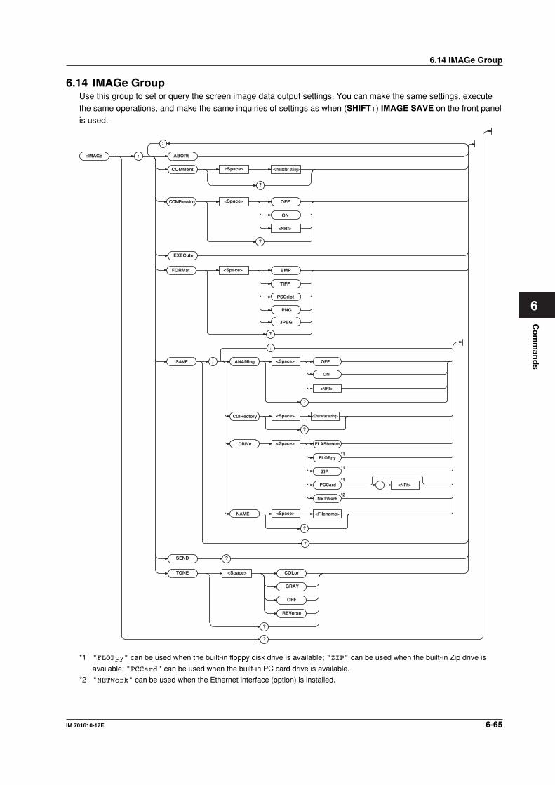
Co
mm
and
s
6-65IM 701610-17E
6
6.14 IMAGe GroupUse this group to set or query the screen image data output settings. You can make the same settings, executethe same operations, and make the same inquiries of settings as when (SHIFT+) IMAGE SAVE on the front panelis used.
:IMAGe : ABORt
COMMent <Character string>
EXECute
<Space>
?
;
COMPression <Space> OFF
ON
<NRf>
?
FORMat <Space> BMP
TIFF
PSCript
PNG
SEND ?
TONE <Space> COLor
OFF
GRAY
REVerse
?
?
?
?
<Space>
<NRf>
SAVE ANAMing;
;
ON
OFF
<Space> <Character string>CDIRectory
?
<Space> <Filename>NAME
<Space>DRIVe
NETWork
FLAShmem
ZIP
?
?
PCCard <NRf>,
*1
FLOPpy*1
*2
*1
JPEG
*1 "FLOPpy" can be used when the built-in floppy disk drive is available; "ZIP" can be used when the built-in Zip drive is
available; "PCCard" can be used when the built-in PC card drive is available.
*2 "NETWork" can be used when the Ethernet interface (option) is installed.
6.14 IMAGe Group
6-66 IM 701610-17E
6.14 IMAGe Group
:IMAGe?Function Queries all screen image data output settings.
Syntax IMAGe?
Example :IMAGE? -> :IMAGE:FORMAT TIFF;
TONE OFF;COMMENT "";COMPRESSION 0;
SAVE:ANAMING 1;NAME ""
:IMAGe:ABORtFunction Aborts saving the screen image data to the
storage medium.
Syntax :IMAGe:ABORt
Example :IMAGE:ABORT
:IMAGe:COMMentFunction Sets the comment at the lower right corner of
the screen or queries the current setting.
Syntax :IMAGe:COMMent <Character string>
:IMAGe:COMMent?
Example :IMAGE:COMMENT "THIS IS TEST."
:IMAGE:COMMENT? -> :IMAGE:
COMMENT "THIS IS TEST."
:IMAGe:COMPressionFunction Enables or disables the screen data
compression of the BMP format or queries the
current setting.
Syntax :IMAGe:COMPression <Boolean>
:IMAGe:COMPression?
Example :IMAGE:COMPRESSION ON
:IMAGE:COMPRESSION? -> :IMAGE:
COMPRESSION 1
Description This setting is valid when saving to the external
storage medium.
:IMAGe:EXECuteFunction Stores the screen image data to the storage
medium.
Syntax :IMAGe:EXECute
Example :IMAGE:EXECUTE
:IMAGe:FORMatFunction Sets/queries the screen image data output
format.
Syntax :IMAGe:FORMat TIFF|BMP|PSCRipt|
PNG|JPEG :IMAGe:FORMat?
Example :IMAGE:FORMAT TIFF
:IMAGE:FORMAT? -> :IMAGE:
FORMAT TIFF
:IMAGe:SAVE?Function Queries all settings related to file output.
Syntax :IMAGe:SAVE?
Example :IMAGE:SAVE? -> :IMAGE:SAVE:
DRIVE FLOPPY;DIRECTORY "NO_1";
ANAMING 0;NAME "DISP_1"
:IMAGe:SAVE:ANAMingFunction Turns ON/OFF the auto naming function of
output file names or queries the current setting.
Syntax :IMAGe:ANAMing <Boolean>
:IMAGe:SAVE:ANAMing?
Example :IMAGE:ANAMING ON
:IMAGE:SAVE:ANAMING? -> :IMAGE:
SAVE:ANAMING 1
:IMAGe:SAVE:CDIRectoryFunction Changes the file directory.
Syntax :IMAGe:SAVE:DIRectory <Character
string>
<Character string>= Up to eight
characters.
Example :IMAGE:SAVE:DIRECTORY "NO_1"
:IMAGe:SAVE:DRIVeFunction Sets the medium on which to create the file.
Syntax :IMAGe:SAVE:DRIVe FLOPpy|FLAShmem|
PCCard[,<NRf>]|ZIP|
NETWork
:IMAGe:SAVE:DRIVe?
<NRf>=0 to 3
Example :IMAGE:SAVE:DRIVE FLOPPY
:IMAGE:SAVE:DRIVE? -> :IMAGE:SAVE:
DRIVE FLOPPY
Description If the PC card drive does not contain partitions,
omit the <NRf>. "Floppy" can be used when
the built-in floppy disk drive is avaliable; "ZIP"
can be used when the built-in Zip drive is
avaliable; "PCCard" can be used when built-in
PC card drive is avaliable. "NETWork" can be
used when the Ethernet interface (option) is
installed.
:IMAGe:SAVE:NAMEFunction Sets the name of the file to be created or
queries the current setting.
Syntax :IMAGe:SAVE:NAME <Filename>
:IMAGe:SAVE:NAME?
Example :IMAGE:SAVE:NAME "DISP_1"
:IMAGE:SAVE:NAME? -> :IMAGE:SAVE:
NAME "DISP_1"
6-67IM 701610-17E
Co
mm
and
s
6
:IMAGe:SEND?Function Queries screen image data.
Syntax :IMAGe:SEND?
Example :IMAGE:SEND? -> #6 (number of
bytes[6-digit value]) (Data byte
string) (Block data)
Description Number of bytes in <block data> is
(2+6+Number of data+1(delimiter). For
information about block data, refer to page 5-6.
6.15 INITialize GroupThe commands in the INITialize group are related to initializing. You can make the same settings using theInitialize menu of SETUP on the front panel.
:INITializ e : EXECute
UNDO
:INITialize:EXECuteFunction Executes initializing.
Syntax :INITialize:EXECute
Example :INITIALIZE:EXECUTE
:INITialize:UNDOFunction Nullifies initializing.
Syntax :INITialize:UNDO
Example :INITIALIZE:UNDO
:IMAGe:TONEFunction Sets/queries the color tone of the BMP (TIFF)
format of the screen image data to output.
Syntax :IMAGe:TONE COLor|OFF|REVerse|
GRAY
:IMAGe:TONE?
Example :IMAGE:TONE COLOR
:IMAGE:TONE? -> :IMAGE:TONE COLOR
6.14 IMAGe Group/6.15 INITialize Group
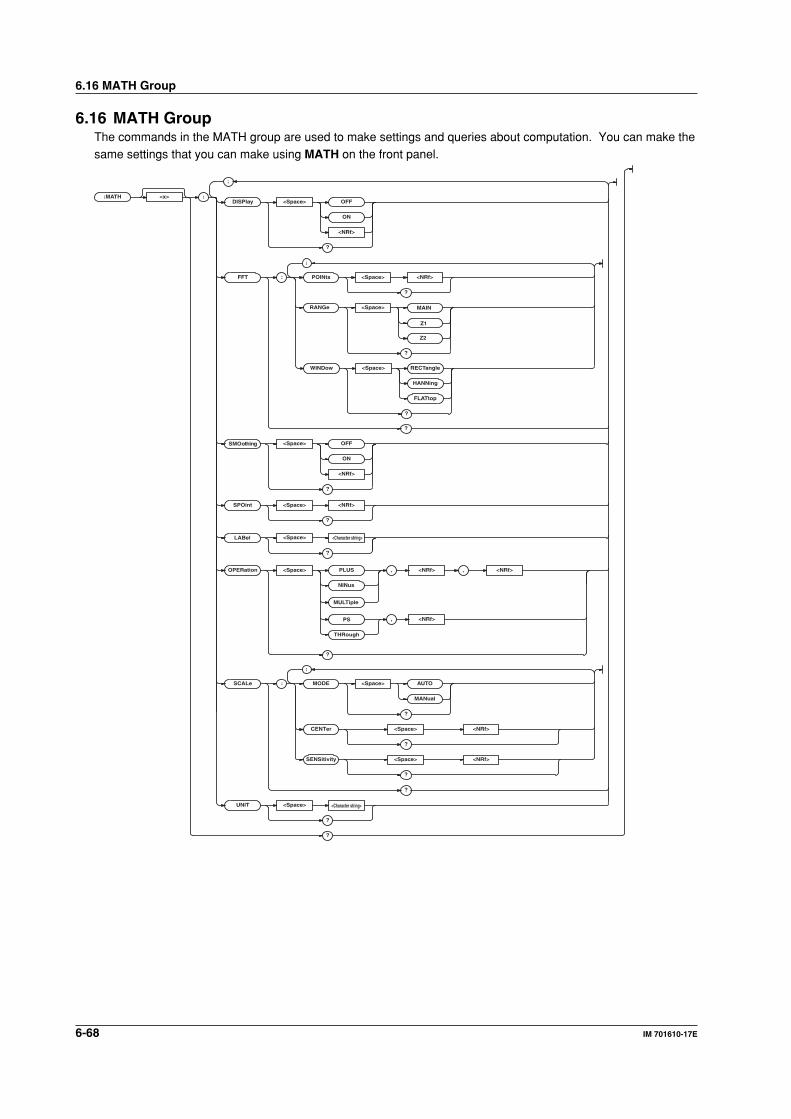
6-68 IM 701610-17E
6.16 MATH Group
6.16 MATH GroupThe commands in the MATH group are used to make settings and queries about computation. You can make thesame settings that you can make using MATH on the front panel.
:MATH <x> :DISPlay <Space> OFF
ON
<NRf>
?
FFT : POINts <Space> <NRf>
?
SPOint <Space> <NRf>
?
RANGe <Space> MAIN
Z1
Z2
?
?
SMOothing <Space> OFF
ON
<NRf>
?
LABel <Space>
?
OPERation <Space> PLUS , <NRf> , <NRf>
NINus
MUL Tiple
?
, <NRf>PS
THRough
SCALe : MODE <Space> AUTO
MANual
?
CENTer <Space> <NRf>
?
?
UNIT <Space>
?
?
;
;
SENSitivity <Space> <NRf>
?
;
WINDow <Space> RECTangle
HANNing
FLATtop
?
<Character string>
<Character string>
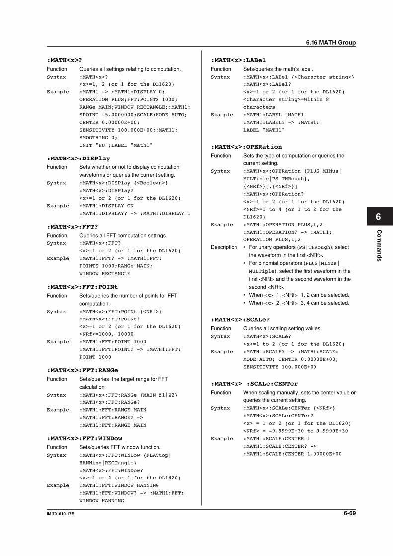
6-69IM 701610-17E
Co
mm
and
s
6
:MATH<x>?Function Queries all settings relating to computation.
Syntax :MATH<x>?
<x>=1, 2 (or 1 for the DL1620)
Example :MATH1 -> :MATH1:DISPLAY 0;
OPERATION PLUS;FFT:POINTS 1000;
RANGe MAIN;WINDOW RECTANGLE;:MATH1:
SPOINT -5.0000000;SCALE:MODE AUTO;
CENTER 0.00000E+00;
SENSITIVITY 100.000E+00;:MATH1:
SMOOTHING 0;
UNIT "EU";LABEL "Math1"
:MATH<x>:DISPlayFunction Sets whether or not to display computation
waveforms or queries the current setting.
Syntax :MATH<x>:DISPlay <Boolean>
:MATH<x>:DISPlay?
<x>=1 or 2 (or 1 for the DL1620)
Example :MATH1:DISPLAY ON
:MATH1:DIPSLAY? -> :MATH1:DISPLAY 1
:MATH<x>:FFT?Function Queries all FFT computation settings.
Syntax :MATH<x>:FFT?
<x>=1 or 2 (or 1 for the DL1620)
Example :MATH1:FFT? -> :MATH1:FFT:
POINTS 1000;RANGe MAIN;
WINDOW RECTANGLE
:MATH<x>:FFT:POINtFunction Sets/queries the number of points for FFT
computation.
Syntax :MATH<x>:FFT:POINt <NRf>
:MATH<x>:FFT:POINt?
<x>=1 or 2 (or 1 for the DL1620)
<NRf>=1000, 10000
Example :MATH1:FFT:POINT 1000
:MATH1:FFT:POINT? -> :MATH1:FFT:
POINT 1000
:MATH<x>:FFT:RANGeFunction Sets/queries the target range for FFT
calculation
Syntax :MATH<x>:FFT:RANGe MAIN|Z1|Z2
:MATH<x>:FFT:RANGe?
Example :MATH1:FFT:RANGE MAIN
:MATH1:FFT:RANGE? ->
:MATH1:FFT:RANGE MAIN
:MATH<x>:FFT:WINDowFunction Sets/queries FFT window function.
Syntax :MATH<x>:FFT:WINDow FLATtop|
HANNing|RECTangle
:MATH<x>:FFT:WINDow?
<x>=1 or 2 (or 1 for the DL1620)
Example :MATH1:FFT:WINDOW HANNING
:MATH1:FFT:WINDOW? -> :MATH1:FFT:
WINDOW HANNING
:MATH<x>:LABelFunction Sets/queries the math’s label.
Syntax :MATH<x>:LABel <Character string>
:MATH<x>:LABel?
<x>=1 or 2 (or 1 for the DL1620)
<Character string>=Within 8
characters
Example :MATH1:LABEL "MATH1"
:MATH1:LABEL? -> :MATH1:
LABEL "MATH1"
:MATH<x>:OPERationFunction Sets the type of computation or queries the
current setting.
Syntax :MATH<x>:OPERation PLUS|MINus|
MULTiple|PS|THRough,
<NRf>[,<NRf>]
:MATH<x>:OPERation?
<x>=1 or 2 (or 1 for the DL1620)
<NRf>=1 to 4 (or 1 to 2 for the
DL1620)
Example :MATH1:OPERATION PLUS,1,2
:MATH1:OPERATION? -> :MATH1:
OPERATION PLUS,1,2
Description • For unary operators (PS|THRough), select
the waveform in the first <NRf>.
• For binomial operators (PLUS|MINus|
MULTiple), select the first waveform in the
first <NRf> and the second waveform in the
second <NRf>.
• When <x>=1, <NRf>=1, 2 can be selected.
• When <x>=2, <NRf>=3, 4 can be selected.
:MATH<x>:SCALe?Function Queries all scaling setting values.
Syntax :MATH<x>:SCALe?
<x>=1 to 2 (or 1 for the DL1620)
Example :MATH1:SCALE? -> :MATH1:SCALE:
MODE AUTO; CENTER 0.00000E+00;
SENSITIVITY 100.000E+00
:MATH<x> :SCALe:CENTerFunction When scaling manually, sets the center value or
queries the current setting.
Syntax :MATH<x>:SCALe:CENTer <NRf>
:MATH<x>:SCALe:CENTer?
<x> = 1 or 2 (or 1 for the DL1620)
<NRf> = -9.9999E+30 to 9.9999E+30
Example :MATH1:SCALE:CENTER 1
:MATH1:SCALE:CENTER? ->
:MATH1:SCALE:CENTER 1.00000E+00
6.16 MATH Group
6-70 IM 701610-17E
6.16 MATH Group
:MATH<x>:SCALe:MODEFunction Sets/queries the scaling method.
Syntax :MATH<x>:SCALe:MODE AUTO|MANual
:MATH<x>:SCALe:MODE?
<x>=1 or 2 (or 1 for the DL1620)
Example :MATH1:SCALE:MODE AUTO
:MATH1:SCALE:MODE? -> :MATH1:SCALE:
MODE AUTO
:MATH<x>:SCALe:SENSitivityFunction When scaling manually, sets the span from the
center or queries the current setting.
Syntax :MATH<x>:SCALe:SENSitivity <NRf>
:MATH<x>:SCALe:SENSitivity?
<x> = 1 or 2 (or 1 for the DL1620)
<NRf> = -9.9999E+30 to 9.9999E+30
Example :MATH1:SCALE:SENSITIVITY 10
:MATH1:SCALE:SENSITIVITY? ->
:MATH1:SCALE:SENSITIVITY
10.0000E+00
:MATH<x>:SMOothingFunction Turns smoothing ON/OFF or queries the
current setting.
Syntax :MATH<x>:SMOothing <Boolean>
:MATH<x>:SMOothing?
<x>=1 or 2 (or 1 for the DL1620)
Example :MATH1:SMOOTHING ON
:MATH1:SMOOTHING? -> :MATH1:
SMOOTHING 1
Description This command is void, if "PS" is selected with
the "MATH<x>:OPERation" command.
:MATH<x>:SPOintFunction Sets the start point or queries the current
setting.
Syntax :MATH<x>:SPOint <NRf>
:MATH<x>:POINt?
<x>=1 or 2 (or 1 for the DL1620)
<NRf> = -5 to 5 div (10 div/
displayed record length steps)
Example :MATH1:SPOINT 1.5
:MATH1:SPOINT? -> :MATH1:SPOINT
1.5000000
:MATH<x>:UNITFunction Sets/queries the dimensional unit appended to
computation result.
Syntax :MATH<x>:UNIT <Character string>
:MATH<x>:UNIT?
<x>=1 or 2 (or 1 for the DL1620)
<Character string>=Within 4
characters
Example :MATH1:UNIT "EU"
:MATH1:UNIT? -> :MATH1:UNIT "EU"
Description The unit is reflected in the scale value. The unit
setting has no effect on the calculation result.
Co
mm
and
s
6-71IM 701610-17E
6
6.17 MEASure GroupThe commands in the MEASure group are used to make settings and queries about automatic measurement ofwaveform parameters. You can make the same settings which you can make using MEASURE on the frontpanel.
:MEASure :
CHANnel
MATH
<x>
<x>
: ALL <Space> OFF
ON
<NRf>
COPY
DELay : COUNt ?
SDEViation ?
MAXimum ?
MEAN ?
MEASure : COUNt <Space> <NRf>
?
<Space> <NRf>
SLOPe <Space> RISE
FALL
?
?
MINimum ?
STAT e <Space> OFF
DEGRee
ON
?
REFerence : COUNt <Space> <NRf>
?
SLOPe <Space>
TRACe
FALL
?
TRACe <Space> <NRf>
MATH <x>
?
VALue ?
?
DPRoximal : MODE <Space> UNIT
PERCent
?
PERCent <Space> <NRf> , <NRf> , <NRf>
<NRf>
*1 *1 *1
, <NRf> , <NRf>
?
UNIT <Space> , , <Voltage>
?
<Space>
RISE
TRIGger
?
SOURce
;
;
<Voltage><Voltage>
;
;
;
;
?
?
AMODe <Space> NORMal
AREA 2
?
6.17 MEASure Group
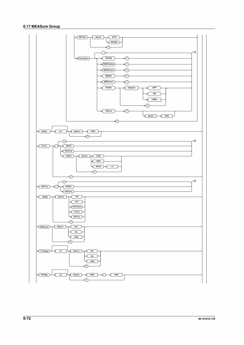
6-72 IM 701610-17E
6.17 MEASure Group
<Parameter>
?
MODE <Space> ON
OFF
STATistics
CYCLe
HISTory
?
TRANge <Space> <NRf> , <NRf>
?
CONSt <X> <Space> <NRf>
?
<X>
COUNt ?
SDEViation ?
MAXimum ?
MEAN ?
MINimum ?
STAT e <Space> OFF
ON
<NRf>
?
VALue ?
;
CYCLe : ABORt
EXECute
<x>
TRACe OWN
MATH
<Space>
?
<NRf>
?
HISTory : ABORt
EXECute
;
;
METHod <Space> AUTO
MAXMin
?
<Space>
<NRf>
OFF
ON
?
ONECycle
<X>
<Space>
<NRf>
OFF
ON
?
TLINkage
<Space> <NRf>

Co
mm
and
s
6-73IM 701610-17E
6
?
WAIT ? <Space> <NRf>
<NRf>
?
VALue ?
OPERation
?
<Space>
MULTiple
MiNus
PLUS
DIVision
SDEVitation ?
STATe
?
<Space>
ON
OFF
<Character string>UNIT
?
<Space>
?
USER <X> <Space> <NRf>AREA <X>:
;
;
TRACe:
COUNt ?
MAXimum ?
MEAN ?
MINimum ?
NONE
<x>MATH
<Space> <Parameter>ITEM
<x>CONSt
?
?
<Space> <NRf>
*1 When using a current probe, becomes <Current>.
6.17 MEASure Group
6-74 IM 701610-17E
6.17 MEASure Group
:MEASure?Function Queries all settings relating to automatic
measurement of waveform parameters.
Syntax :MEASure?
Example :MEASURE? -> :MEASURE:MODE ON;
AMODE NORMAL;CHANNEL1:AVERAGE:
STATE 0;:MEASURE:CHANNEL1:AVGFREQ:
STATE 0;:MEASURE:CHANNEL1:
AVGPERIOD:STATE 0;:MEASURE:
CHANNEL1:BWIDTH1:STATE 0;:MEASURE:
CHANNEL1:BWIDTH2:STATE 0;:MEASURE:
CHANNEL1:DUTYCYCLE:STATE 0;:
MEASURE:CHANNEL1:FALL:STATE 0;:
MEASURE:CHANNEL1:FREQUENCY:
STATE 0;:MEASURE:CHANNEL1:HIGH:
STATE 0;:MEASURE:CHANNEL1:LOW:
STATE 0;:MEASURE:CHANNEL1:MAXIMUM:
STATE 0;:MEASURE:CHANNEL1:MINIMUM:
STATE 0;:MEASURE:CHANNEL1:
NOVERSHOOT:STATE 0;:MEASURE:
CHANNEL1:NWIDTH:STATE 0;:MEASURE:
CHANNEL1:PERIOD:STATE 0;:MEASURE:
CHANNEL1:PNUMBER:STATE 0;:MEASURE:
CHANNEL1:POVERSHOOT:STATE 0;:
MEASURE:CHANNEL1:PTOPEAK:STATE 1;:
MEASURE:CHANNEL1:PWIDTH:STATE 0;:
MEASURE:CHANNEL1:RISE:STATE 0;:
MEASURE:CHANNEL1:RMS:STATE 0;:
MEASURE:CHANNEL1:SDEVIATION:
STATE 0;:MEASURE:CHANNEL1:TY1INTEG:
STATE 0;:MEASURE:CHANNEL1:TY2INTEG:
STATE 0;:MEASURE:CHANNEL1:XY1INTEG:
STATE 0;:MEASURE:CHANNEL1:XY2INTEG:
STATE 0;:MEASURE:CHANNEL1:DELAY:
STATE OFF;MEASURE:SLOPE RISE;
COUNT 1;:MEASURE:CHANNEL1:DELAY:
REFERENCE:SOURCE TRACE;TRACE 1;
SLOPE RISE;COUNT 1;:MEASURE:
CHANNEL1:DPROXIMAL:MODE PERCENT;
PERCENT 10.0,50.0,90.0;
UNIT -150.000E+00,0.0E+00,
150.000E+00;:MEASURE:CHANNEL1:
METHOD AUTO;:MEASURE:CHANNEL2:
AVERAGE:STATE 0;:MEASURE:CHANNEL2:
AVGFREQ:STATE 0;:MEASURE:CHANNEL2:
AVGPERIOD:STATE 0;:MEASURE:
CHANNEL2:BWIDTH1:STATE 0;:MEASURE:
CHANNEL2:BWIDTH2:STATE 0;:MEASURE:
CHANNEL2:DUTYCYCLE:STATE 0;:
MEASURE:CHANNEL2:FALL:STATE 0;:
MEASURE:CHANNEL2:FREQUENCY:
STATE 0;:MEASURE:CHANNEL2:HIGH:
STATE 0;:MEASURE:CHANNEL2:LOW:
STATE 0;:MEASURE:CHANNEL2:MAXIMUM:
STATE 0;:MEASURE:CHANNEL2:MINIMUM:
STATE 0;:MEASURE:CHANNEL2:
NOVERSHOOT:STATE 0;:MEASURE:
CHANNEL2:NWIDTH:STATE 0;:MEASURE:
CHANNEL2:PERIOD:STATE 0;:MEASURE:
CHANNEL2:PNUMBER:STATE 0;:MEASURE:
CHANNEL2:POVERSHOOT:STATE 0;:
MEASURE:CHANNEL2:PTOPEAK:STATE 0;:
MEASURE:CHANNEL2:PWIDTH:STATE 0;:
MEASURE:CHANNEL2:RISE:STATE 0;:
MEASURE:CHANNEL2:RMS:STATE 0;:
MEASURE:CHANNEL2:SDEVIATION:
STATE 0;:MEASURE:CHANNEL2:TY1INTEG:
STATE 0;:MEASURE:CHANNEL2:TY2INTEG:
STATE 0;:MEASURE:CHANNEL2:XY1INTEG:
STATE 0;:MEASURE:CHANNEL2:XY2INTEG:
STATE 0;:MEASURE:CHANNEL2:DELAY:
STATE OFF;MEASURE:SLOPE RISE;
COUNT 1;:MEASURE:CHANNEL2:DELAY:
REFERENCE:SOURCE TRACE;TRACE 2;
SLOPE RISE;COUNT 1;:MEASURE:
CHANNEL2:DPROXIMAL:MODE PERCENT;
PERCENT 10.0,50.0,90.0;
UNIT -150.000E+00,0.0E+00,
150.000E+00;:MEASURE:CHANNEL2:
METHOD AUTO;:MEASURE:CHANNEL3:
AVERAGE:STATE 0;:MEASURE:CHANNEL3:
AVGFREQ:STATE 0;:MEASURE:CHANNEL3:
AVGPERIOD:STATE 0;:MEASURE:
CHANNEL3:BWIDTH1:STATE 0;:MEASURE:
CHANNEL3:BWIDTH2:STATE 0;:MEASURE:
CHANNEL3:DUTYCYCLE:STATE 0;:
MEASURE:CHANNEL3:FALL:STATE 0;:
MEASURE:CHANNEL3:FREQUENCY:
STATE 0;:MEASURE:CHANNEL3:HIGH:
STATE 0;:MEASURE:CHANNEL3:LOW:
STATE 0;:MEASURE:CHANNEL3:MAXIMUM:
STATE 0;:MEASURE:CHANNEL3:MINIMUM:
STATE 0;:MEASURE:CHANNEL3:
NOVERSHOOT:STATE 0;:MEASURE:
CHANNEL3:NWIDTH:STATE 0;:MEASURE:
CHANNEL3:PERIOD:STATE 0;:MEASURE:
CHANNEL3:PNUMBER:STATE 0;:MEASURE:
CHANNEL3:POVERSHOOT:STATE 0;:
MEASURE:CHANNEL3:PTOPEAK:STATE 0;:
MEASURE:CHANNEL3:PWIDTH:STATE 0;:
MEASURE:CHANNEL3:RISE:STATE 0;:
MEASURE:CHANNEL3:RMS:STATE 0;:
MEASURE:CHANNEL3:SDEVIATION:
STATE 0;:MEASURE:CHANNEL3:TY1INTEG:
STATE 0;:MEASURE:CHANNEL3:TY2INTEG:
STATE 0;:MEASURE:CHANNEL3:XY1INTEG:
STATE 0;:MEASURE:CHANNEL3:XY2INTEG:
STATE 0;:MEASURE:CHANNEL3:DELAY:
STATE OFF;MEASURE:SLOPE RISE;
COUNT 1;:MEASURE:CHANNEL3:DELAY:
REFERENCE:SOURCE TRACE;TRACE 3;
SLOPE RISE;COUNT 1;:MEASURE:
CHANNEL3:DPROXIMAL:MODE PERCENT;
PERCENT 10.0,50.0,90.0;
UNIT -150.000E+00,0.0E+00,
150.000E+00;:MEASURE:CHANNEL3:
METHOD AUTO;:MEASURE:CHANNEL4:
AVERAGE:STATE 0;:MEASURE:CHANNEL4:
6-75IM 701610-17E
Co
mm
and
s
6
AVGFREQ:STATE 0;:MEASURE:CHANNEL4:
AVGPERIOD:STATE 0;:MEASURE:
CHANNEL4:BWIDTH1:STATE 0;:MEASURE:
CHANNEL4:BWIDTH2:STATE 0;:MEASURE:
CHANNEL4:DUTYCYCLE:STATE 0;:
MEASURE:CHANNEL4:FALL:STATE 0;:
MEASURE:CHANNEL4:FREQUENCY:
STATE 0;:MEASURE:CHANNEL4:HIGH:
STATE 0;:MEASURE:CHANNEL4:LOW:
STATE 0;:MEASURE:CHANNEL4:MAXIMUM:
STATE 0;:MEASURE:CHANNEL4:MINIMUM:
STATE 0;:MEASURE:CHANNEL4:
NOVERSHOOT:STATE 0;:MEASURE:
CHANNEL4:NWIDTH:STATE 0;:MEASURE:
CHANNEL4:PERIOD:STATE 0;:MEASURE:
CHANNEL4:PNUMBER:STATE 0;:MEASURE:
CHANNEL4:POVERSHOOT:STATE 0;:
MEASURE:CHANNEL4:PTOPEAK:STATE 0;:
MEASURE:CHANNEL4:PWIDTH:STATE 0;:
MEASURE:CHANNEL4:RISE:STATE 0;:
MEASURE:CHANNEL4:RMS:STATE 0;:
MEASURE:CHANNEL4:SDEVIATION:
STATE 0;:MEASURE:CHANNEL4:TY1INTEG:
STATE 0;:MEASURE:CHANNEL4:TY2INTEG:
STATE 0;:MEASURE:CHANNEL4:XY1INTEG:
STATE 0;:MEASURE:CHANNEL4:XY2INTEG:
STATE 0;:MEASURE:CHANNEL4:DELAY:
STATE OFF;MEASURE:SLOPE RISE;
COUNT 1;:MEASURE:CHANNEL4:DELAY:
REFERENCE:SOURCE TRACE;TRACE 4;
SLOPE RISE;COUNT 1;:MEASURE:
CHANNEL4:DPROXIMAL:MODE PERCENT;
PERCENT 10.0,50.0,90.0;
UNIT -150.000E+00,0.0E+00,
150.000E+00;:MEASURE:CHANNEL4:
METHOD AUTO;:MEASURE:MATH1:AVERAGE:
STATE 0;:MEASURE:MATH1:AVGFREQ:
STATE 0;:MEASURE:MATH1:AVGPERIOD:
STATE 0;:MEASURE:MATH1:BWIDTH1:
STATE 0;:MEASURE:MATH1:BWIDTH2:
STATE 0;:MEASURE:MATH1:DUTYCYCLE:
STATE 0;:MEASURE:MATH1:FALL:
STATE 0;:MEASURE:MATH1:FREQUENCY:
STATE 0;:MEASURE:MATH1:HIGH:
STATE 0;:MEASURE:MATH1:LOW:
STATE 0;:MEASURE:MATH1:MAXIMUM:
STATE 0;:MEASURE:MATH1:MINIMUM:
STATE 0;:MEASURE:MATH1:NOVERSHOOT:
STATE 0;:MEASURE:MATH1:NWIDTH:
STATE 0;:MEASURE:MATH1:PERIOD:
STATE 0;:MEASURE:MATH1:PNUMBER:
STATE 0;:MEASURE:MATH1:POVERSHOOT:
STATE 0;:MEASURE:MATH1:PTOPEAK:
STATE 0;:MEASURE:MATH1:PWIDTH:
STATE 0;:MEASURE:MATH1:RISE:
STATE 0;:MEASURE:MATH1:RMS:
STATE 0;:MEASURE:MATH1:SDEVIATION:
STATE 0;:MEASURE:MATH1:TY1INTEG:
STATE 0;:MEASURE:MATH1:TY2INTEG:
STATE 0;:MEASURE:MATH1:XY1INTEG:
STATE 0;:MEASURE:MATH1:XY2INTEG:
STATE 0;:MEASURE:MATH1:DELAY:
STATE OFF;MEASURE:SLOPE RISE;
COUNT 1;:MEASURE:MATH1:DELAY:
REFERENCE:SOURCE TRACE;TRACE MATH1;
SLOPE RISE;COUNT 1;:MEASURE:MATH1:
DPROXIMAL:MODE PERCENT;
PERCENT 10.0,50.0,90.0;UNIT -3.00,
0.00,3.00;:MEASURE:MATH1:
METHOD AUTO;:MEASURE:MATH2:AVERAGE:
STATE 0;:MEASURE:MATH2:AVGFREQ:
STATE 0;:MEASURE:MATH2:AVGPERIOD:
STATE 0;:MEASURE:MATH2:BWIDTH1:
STATE 0;:MEASURE:MATH2:BWIDTH2:
STATE 0;:MEASURE:MATH2:DUTYCYCLE:
STATE 0;:MEASURE:MATH2:FALL:
STATE 0;:MEASURE:MATH2:FREQUENCY:
STATE 0;:MEASURE:MATH2:HIGH:
STATE 0;:MEASURE:MATH2:LOW:
STATE 0;:MEASURE:MATH2:MAXIMUM:
STATE 0;:MEASURE:MATH2:MINIMUM:
STATE 0;:MEASURE:MATH2:NOVERSHOOT:
STATE 0;:MEASURE:MATH2:NWIDTH:
STATE 0;:MEASURE:MATH2:PERIOD:
STATE 0;:MEASURE:MATH2:PNUMBER:
STATE 0;:MEASURE:MATH2:POVERSHOOT:
STATE 0;:MEASURE:MATH2:PTOPEAK:
STATE 0;:MEASURE:MATH2:PWIDTH:
STATE 0;:MEASURE:MATH2:RISE:
STATE 0;:MEASURE:MATH2:RMS:
STATE 0;:MEASURE:MATH2:SDEVIATION:
STATE 0;:MEASURE:MATH2:TY1INTEG:
STATE 0;:MEASURE:MATH2:TY2INTEG:
STATE 0;:MEASURE:MATH2:XY1INTEG:
STATE 0;:MEASURE:MATH2:XY2INTEG:
STATE 0;:MEASURE:MATH2:DELAY:
STATE OFF;MEASURE:SLOPE RISE;
COUNT 1;:MEASURE:MATH2:DELAY:
REFERENCE:SOURCE TRACE;TRACE MATH2;
SLOPE RISE;COUNT 1;:MEASURE:MATH2:
DPROXIMAL:MODE PERCENT;
PERCENT 10.0,50.0,90.0;UNIT -3.00,
0.00,3.00;:MEASURE:MATH2:
METHOD AUTO;:MEASURE:USER1:STATE 0;
AREA1:TRACE 1;ITEM PTOPEAK;:
MEASURE:USER1:AREA2:TRACE 2;
ITEM MAXIMUM;:MEASURE:USER1:
OPERATION PLUS;UNIT "";:MEASURE:
USER2:STATE 0;AREA1:TRACE 3;
ITEM MINIMUM;:MEASURE:USER2:AREA2:
TRACE 4;ITEM RMS;:MEASURE:USER2:
OPERATION MINUS;UNIT "";:MEASURE:
USER3:STATE 0;AREA1:TRACE MATH1;
ITEM PERIOD;:MEASURE:USER3:AREA2:
TRACE MATH2;ITEM AVGPERIOD;:
MEASURE:USER3:OPERATION MULTIPLE;
UNIT "";:MEASURE:USER4:STATE 0;
AREA1:TRACE NONE;ITEM XY1INTEG;:
6.17 MEASure Group
6-76 IM 701610-17E
6.17 MEASure Group
MEASURE:USER4:AREA2:TRACE CONST1;
ITEM XY2INTEG;:MEASURE:USER4:
OPERATION DIVISION;UNIT "";:
MEASURE:CONST1 1.00000E+00;
CONST2 1.00000E+00;
CONST3 1.00000E+00;
CONST4 1.00000E+00;CYCLE:TRACE 1;:
MEASURE:ONECYCLE 0;TLINKAGE1 0;
TLINKAGE2 0;TRANGE1 -5.0000000,
5.0000000;TRANGE2 -5.0000000,
5.0000000
:MEASure:AMODeFunction Sets whether to perform the automated
measurement of waveform parameters on a
normal single area (NORMal) or dual areas
(AREA2) or queries the current setting.
Syntax :MEASure:AMODe NORMal|AREA2
:MEASure:AMODe?
Example :MEASURE:AMODE AREA2:MEASURE:AMODE?
-> :MEASURE:AMODE AREA2
:MEASure:CHANnel<x>|MATH<x>?Function Queries all specified parameter ON/OFF
settings.
Syntax :MEASure:CHANnel<x>|MATH<x>?
<x> (CHANnel)=1 to 4 (or 1 to 2 for
the DL1620)
<x> (MATH)=1 or 2 (or 1 for the
DL1620)
Example (An example for CH1 is given
below.)
:MEASURE:CHANNEL1? -> :MEASURE:
CHANNEL1:AVERAGE:STATE 0;:MEASURE:
CHANNEL1:AVGFREQ:STATE 0;:MEASURE:
CHANNEL1:AVGPERIOD:STATE 0;:
MEASURE:CHANNEL1:BWIDTH1:STATE 0;:
MEASURE:CHANNEL1:BWIDTH2:STATE 0;:
MEASURE:CHANNEL1:DUTYCYCLE:
STATE 0;:MEASURE:CHANNEL1:FALL:
STATE 0;:MEASURE:CHANNEL1:
FREQUENCY:STATE 0;:MEASURE:
CHANNEL1:HIGH:STATE 0;:MEASURE:
CHANNEL1:LOW:STATE 0;:MEASURE:
CHANNEL1:MAXIMUM:STATE 0;:
MEASURE:CHANNEL1:MINIMUM:STATE 0;:
MEASURE:CHANNEL1:NOVERSHOOT:
STATE 0;:MEASURE:CHANNEL1:NWIDTH:
STATE 0;:MEASURE:CHANNEL1:PERIOD:
STATE 0;:MEASURE:CHANNEL1:PNUMBER:
STATE0;:MEASURE:CHANNEL1:
POVERSHOOT:STATE 0;:MEASURE:
CHANNEL1:PTOPEAK:STATE 0;:MEASURE:
CHANNEL1:PWIDTH:STATE 0;:MEASURE:
CHANNEL1:RISE:STATE 0;:MEASURE:
CHANNEL1:RMS:STATE 0;:MEASURE:
CHANNEL1:SDEVIATION:STATE 0;:
MEASURE:CHANNEL1:TY1INTEG:STATE 0;:
MEASURE:CHANNEL1:TY2INTEG:STATE 0;:
MEASURE:CHANNEL1:XY1INTEG:STATE 0;:
MEASURE:CHANNEL1:XY2INTEG:STATE 0;:
MEASURE:CHANNEL1:DELAY:STATE 0;
MEASURE:SLOPE RISE;COUNT 1;:
MEASURE:CHANNEL1:DELAY:REFERENCE:
TRACE 1;SLOPE RISE;COUNT 1;:
MEASURE:CHANNEL1:DPROXIMAL:
MODE PERCENT;PERCENT 10.0,50.0,
90.0;UNIT -150.000E+00,0.0E+00,
150.000E+00;:MEASURE:CHANNEL1:
METHOD AUTO 0
:MEASure:CHANnel<x>|MATH<x>:ALLFunction Turns all the measurement parameters of the
waveform ON/OFF at once.
Syntax :MEASure:CHANnel<x>|MATH<x>:
ALL <Boolean>
The <x> in CHANnel<x>=1 to 4 (or 1
to 2 for the DL1620)
The <x> in MATH<x>=1 or 2 (or 1 for
the DL1620)
Example (The following example is for CH1.)
:MEASURE:CHANNEL1:ALL OFF
:MEASure:CHANnel<x>|MATH<x>:COPYFunction Copies the ON/OFF state of all measurement
parameters of one waveform to all other
waveforms.
Syntax :MEASure:CHANnel<x>|MATH<x>:COPY
The <x> in CHANnel<x>=1 to 4 (or 1
to 2 for the DL1620)
The <x> in MATH<x>=1 or 2 (or 1 for
the DL1620)
Example :MEASURE:CHANNEL1:COPY
:MEASure:CHANnel<x>|MATH<x>:DELay?Function Queries all settings related to the delay
between waveform channels.
Syntax :MEASure:CHANnel<x>|MATH<x>:
DELay?
The <x> in CHANnel<x>=1 to 4 (or 1
to 2 for the DL1620)
The <x> in MATH<x>=1 or 2 (or 1 for
the DL1620)
Example :MEASURE:CHANNEL1:DELAY? ->
:MEASURE:CHANNEL1:DELAY:STATE 0;
MEASURE:SLOPE RISE;COUNT 1;:
MEASURE:CHANNEL1:DELAY:REFERENCE:
TRACE 1;SLOPE RISE;COUNT 1
6-77IM 701610-17E
Co
mm
and
s
6
:MEASure:CHANnel<x>|MATH<x>:DELay:
MEASure?Function Queries all settings related to the measured
waveform when measuring the delay between
channels.
Syntax :MEASure:CHANnel<x>|MATH<x>:
DELay:MEASure?
The <x> in CHANnel<x>=1 to 4 (or 1
to 2 for the DL1620)
The <x> in MATH<x>=1 or 2 (or 1 for
the DL1620)
Example :MEASURE:CHANNEL1:DELAY:MEASURE? ->
:MEASURE:CHANNEL1:MEASURE:
SLOPE RISE;COUNT 1
:MEASure:CHANnel<x>|MATH<x>:DELay:
MEASure:COUNtFunction Sets the edge count of the measured waveform
when measuring the delay between channels or
queries the current setting.
Syntax :MEASure:CHANnel<x>|MATH<x>:
DELay:MEASure:COUNt <NRf>
:MEASure:CHANnel<x>|MATH<x>:
DELay:MEASure:COUNt?
The <x> in CHANnel<x>=1 to 4 (or 1
to 2 for the DL1620)
The <x> in MATH<x>=1 or 2 (or 1 for
the DL1620)
<NRf>=1 to 9
Example :MEASURE:CHANNEL1:DELAY:MEASURE:
COUNT 2
:MEASURE:CHANNEL1:DELAY:MEASURE:
COUNT? -> :MEASURE:CHANNEL1:DELAY:
MEASURE:COUNT 2
:MEASure:CHANnel<x>|MATH<x>:DELay:
MEASure:SLOPeFunction Sets the slope of the measured waveform when
measuring the delay between channels or
queries the current setting.
Syntax :MEASure:CHANnel<x>|MATH<x>:
DELay:MEASure:SLOPe RISE|FALL
:MEASure:CHANnel<x>|MATH<x>:
DELay:MEASure:SLOPe?
The <x> in CHANnel<x>=1 to 4 (or 1
to 2 for the DL1620)
The <x> in MATH<x>=1 or 2 (or 1 for
the DL1620)
Example :MEASURE:CHANNEL1:DELAY:MEASURE:
SLOPE RISE
:MEASURE:CHANNEL1:DELAY:MEASURE:
SLOPE? -> :MEASURE:CHANNEL1:DELAY:
MEASURE:SLOPE RISE
:MEASure:CHANnel<x>|MATH<x>:DELay:
REFerence?Function Queries all settings related to the reference
waveform when measuring the delay between
channels.
Syntax :MEASure:CHANnel<x>|MATH<x>:
DELay:REFerence?
The <x> in CHANnel<x>=1 to 4 (or 1
to 2 for the DL1620)
The <x> in MATH<x>=1 or 2 (or 1 for
the DL1620)
Example :MEASURE:CHANNEL1:DELAY:REFERENCE?
-> :MEASURE:CHANNEL1:DELAY:
REFERENCE:TRACE 1;SLOPE RISE;
COUNT 1
:MEASure:CHANnel<x>|MATH<x>:DELay:
REFerence:COUNtFunction Sets the edge count of the reference waveform
when measuring the delay between channels or
queries the current setting.
Syntax :MEASure:CHANnel<x>|MATH<x>:
DELay:REFerence:COUNt <NRf>
:MEASure:CHANnel<x>|MATH<x>:
DELay:REFerence:COUNt?
The <x> in CHANnel<x>=1 to 4 (or 1
to 2 for the DL1620)
The <x> in MATH<x>=1 or 2 (or 1 for
the DL1620)
<NRf>=1 to 9
Example :MEASURE:TRACE1:DELAY:REFERENCE:
COUNT 2
:MEASURE:TRACE1:DELAY:REFERENCE:
COUNT? -> :MEASURE:TRACE1:DELAY:
REFERENCE:COUNT 2
:MEASure:CHANnel<x>|MATH<x>:DELay:
REFerence:SLOPeFunction Sets the slope of the reference waveform when
measuring the delay between channels or
queries the current setting.
Syntax :MEASure:CHANnel<x>|MATH<x>:
DELay:REFerence:SLOPe RISE|FALL
:MEASure:CHANnel<x>|MATH<x>:
DELay:REFerence:SLOPe?
The <x> in CHANnel<x>=1 to 4 (or 1
to 2 for the DL1620)
The <x> in MATH<x>=1 or 2 (or 1 for
the DL1620)
Example :MEASURE:CHANNEL1:DELAY:REFERENCE:
SLOPE RISE
:MEASURE:CHANNEL1:DELAY:REFERENCE:
SLOPE? -> :MEASURE:CHANNEL1:DELAY:
REFERENCE:SLOPE RISE
6.17 MEASure Group
6-78 IM 701610-17E
6.17 MEASure Group
:MEASure:CHANnel<x>|MATH<x>:DELay:
REFerence:SOURceFunction Sets whether or not to set the reference to the
trigger point or the waveform when measuring
the delay between channels or queries the
current setting.
Syntax :MEASure:CHANnel<x>|MATH<x>:
DELay:REFerence:SOURce TRACe|
TRIGger
:MEASure:CHANnel<x>|MATH<x>:
DELay:REFerence:SOURce?
The <x> in CHANnel<x>=1 to 4 (or 1
to 2 for the DL1620)
The <x> in MATH<x>=1 or 2 (or 1 for
the DL1620)
Example :MEASURE:CHANNEL1:DELAY:REFERENCE:
SOURCE TRACE
:MEASURE:CHANNEL1:DELAY:REFERENCE:
SOURCE? -> :MEASURE:CHANNEL1:DELAY:
REFERENCE:SOURCE TRACE
:MEASure:CHANnel<x>|MATH<x>:DELay:
REFerence:TRACeFunction Sets the reference trace when measuring the
delay between channels or queries the current
setting.
Syntax :MEASure:CHANnel<x>|MATH<x>:
DELay:REFerence:TRACe <NRf>|
MATH<x>
:MEASure:CHANnel<x>|MATH<x>:
DELay:REFerence:TRACe?
The <x> in CHANnel<x>=1 to 4 (or 1
to 2 for the DL1620)
The <x> in MATH<x>=1 or 2 (or 1 for
the DL1620)
Example :MEASURE:CHANNEL1:DELAY:REFERENCE:
TRACE 2
:MEASURE:CHANNEL1:DELAY:REFERENCE:
TRACE? -> :MEASURE:CHANNEL1:DELAY:
REFERENCE:TRACE 2
:MEASure:CHANnel<x>|MATH<x>:DELay:
STATeFunction Turns the delay parameter ON/OFF and sets
the display format or queries the current setting.
Syntax :MEASure:CHANnel<x>|MATH<x>:
DELay:STATe OFF|ON|DEGRee
:MEASure:CHANnel<x>|MATH<x>:
DELay:STATe?
The <X> in CHANnel<x>=1 to 4 (or 1
to 2 for the DL1620)
The <X> in MATH<x>=1 or 2 (or 1 for
the DL1620)
Example :MEASURE:CHANNEL1:DELAY:STATE ON
:MEASURE:CHANNEL1:DEALY:STATE? ->
:MEASURE:CHANNEL1:DELAY:STATE ON
:MEASure:CHANnel<x>|MATH<x>:
DPRoximal?Function Queries all settings related to distal, mesial, and
proximal values.
Syntax MEASure:CHANnel<x>|MATH<x>:
DPRoximal?
The <x> in CHANnel<x>=1 to 4 (or 1
to 2 for the DL1620)
The <x> in MATH<x>=1 or 2 (or 1 for
the DL1620)
Example :MEASURE:CHANNEL1:DPROXIMAL? ->
:MEASURE:CHANNEL1:DPROXIMAL:
MODE PERCENT;PERCENT 10.0,50.0,
90.0;UNIT -2.000E+00,0.0E+00,
2.000E+00
:MEASure:CHANnel<x>|MATH<x>:
DPRoximal:MODEFunction Sets the distal, mesial, and proximal mode or
queries the current setting.
Syntax :MEASure:CHANnel<x>|MATH<x>:
DPRoximal:MODE PERCent|UNIT
:MEASure:CHANnel<x>|MATH<x>:
DPRoximal:MODE?
The <x> in CHANnel<x>=1 to 4 (or 1
to 2 for the DL1620)
The <x> in MATH<x>=1 or 2 (or 1 for
the DL1620)
Example :MEASURE:CHANNEL1:DPROXIMAL:MODE
PERCENT
:MEASURE:CHANNEL1:DPROXIMAL:MODE?
-> :MEASURE:CHANNEL1:DPROXIMAL:
MODE PERCENT
:MEASure:CHANnel<x>|MATH<x>:
DPRoximal:PERCentFunction Sets the distal, mesial, and proximal points in
terms of a percentage or queries the current
setting.
Syntax :MEASure:CHANnel<x>|MATH<x>:
DPRoximal:PERCent <NRf>,<NRf>,
<NRf>
:MEASure:CHANnel<x>|MATH<x>:
DPRoximal:PERCent?
The <x> in CHANnel<x>=1 to 4 (or 1
to 2 for the DL1620)
The <x> in MATH<x>=1 or 2 (or 1 for
the DL1620)
<NRf>=0 to 100 (%, 1% steps)
Example :MEASURE:CHANNEL1:DPROXIMAL:PERCENT
80,60,40
:MEASURE:CHANNEL1:DPROXIMAL:
PERCENT? -> :MEASURE:CHANNEL1:
DPROXIMAL:PERCENT 80,60,40
6-79IM 701610-17E
Co
mm
and
s
6
:MEASure:CHANnel<x>|MATH<x>:
DPRoximal:UNITFunction Sets the distal, mesial, and proximal points in
terms of a voltage or queries the current setting.
Syntax :MEASure:CHANnel<x>|MATH<x>:
DPRoximal:UNIT <voltage>,
<voltage>,<voltage>|<NRf>,<NRf>,
<NRf>
:MEASure:CHANnel<x>|MATH<x>:
DPRoximal:UNIT?
The <x> in CHANnel<x>=1 to 4 (or 1
to 2 for the DL1620)
The <x> in MATH<x>=1 or 2 (or 1 for
the DL1620)
<voltage>=8 div on the screen (0.01
div steps)
<NRf>=–4 to 4 div (0.01 div steps)
Example :MEASURE:CHANNEL1:DPROXIMAL:UNIT
50V,0V,-50V
:MEASURE:CHANNEL1:DPROXIMAL:UNIT?
-> :MEASURE:CHANNEL1:DPROXIMAL:
UNIT 50.0E+00,0.0E+00,-50.0E+00
Description When set to the current probe, sets the
<Current> value or queries the current setting.
:MEASure:CHANnel<x>|MATH<x>:METHodFunction Sets the High and Low points or queries the
current setting.
Syntax :MEASure:CHANnel<x>|MATH<x>:
METHod AUTO|MAXMin
:MEASure:CHANnel<x>|MATH<x>:
METHod?
The <x> in CHANnel<x>=1 to 4 (or 1
to 2 for the DL1620)
The <x> in MATH<x>=1 or 2 (or 1 for
the DL1620)
Example :MEASURE:CHANNEL1:METHOD AUTO
:MEASURE:CHANNEL1:METHOD? ->
:MEASURE:CHANNEL1:METHOD AUTO
:MEASure:CHANnel<x>|MATH<x>:
<parameter>?Function Queries all settings related to the parameters of
each waveform.
Syntax :MEASure:CHANnel<x>|MATH<x>:
<parameter>?
The <x> in CHANnel<x>=1 to 4 (or 1
to 2 for the DL1620)
The <x> in MATH<x>=1 or 2 (or 1 for
the DL1620)
<parameter>= AVERage|AVGFreq|
AVGPeriod|BWIDth1|
BWIDth2|DUTYcycle|FALL|
FREQuency|HIGH|LOW|
MAXimum|MINimum|
NOVershoot|NWIDth|
PERiod|PNUMber|POVershoot|
PTOPeak|PWIDth|RISE|RMS|
SDEViation|TY1Integ|
TY2Integ|XY1Integ|
XY2Integ
Example (The following example is for the
average value of CH1.)
:MEASURE:CHANNEL1:AVERAGE? ->
:MEASURE:CHANNEL1:AVERAGE:STATE 1
:MEASure:CHANnel<x>|MATH<x>:
<parameter>:COUNt?Function Queries the number of statistical processing of
each parameter.
Syntax :MEASure:CHANnel<x>|MATH<x>:
<parameter>:COUNt?
The <x> in CHANnel<x>=1 to 4 (or 1
to 2 for the DL1620)
The <x> in MATH<x>=1 or 2 (or 1 for
the DL1620)
<parameter>= AVERage|AVGFreq|
AVGPeriod|BWIDth1|
BWIDth2|DELay|DUTYcycle|
FALL|FREQuency|HIGH|LOW|
MAXimum|MINimum|
NOVershoot|NWIDth|
PERiod|PNUMber|
POVershoot|PTOPeak|
PWIDth|RISE|RMS|
SDEViation|TY1Integ|
TY2Integ|XY1Integ|
XY2Integ
Example (The following example is for the
average value of CH1.)
:MEASURE:CHANNEL1:AVERAGE:COUNT? ->
:MEASURE:CHANNEL1:AVERAGE:COUNT 100
6.17 MEASure Group
6-80 IM 701610-17E
6.17 MEASure Group
:MEASure:CHANnel<x>|MATH<x>:
<parameter>:MAXimum|MEAN|MINimum|
SDEViation?Function Queries the statistics of each parameter.Syntax :MEASure:CHANnel<x>|MATH<x>:
<parameter>:MAXimum|MEAN|MINimum|
SDEViation?
The <x> in CHANnel<x>=1 to 4 (or 1
to 2 for the DL1620)
The <x> in MATH<x>=1 or 2 (or 1 for
the DL1620)
<parameter>= AVERage|AVGFreq|
AVGPeriod|BWIDth1|
BWIDth2|DELay|DUTYcycle|
FALL|FREQuency|HIGH|LOW|
MAXimum|MINimum|
NOVershoot|NWIDth|
PERiod|PNUMber|
POVershoot|PTOPeak|
PWIDth|RISE|RMS|
SDEViation|TY1Integ|
TY2Integ|XY1Integ|
XY2Integ
Example (The following example is for the
maximum value.)
:MEASURE:CHANNEL1:AVERAGE:MAXIMUM?
-> :MEASURE:CHANNEL1:AVERAGE:
MAXIMUM -40.0000E-06
Description If the statistics cannot be found, "NAN (Not ANumber)" is returned.
:MEASure:CHANnel<x>|MATH<x>:
<parameter>:STATeFunction Turns the parameter ON/OFF one by one or
queries the current setting.Syntax :MEASure:CHANnel<x>|MATH<x>:
<parameter>:STATe <Boolean>
:MEASure:CHANnel<x>|MATH<x>:
<parameter>:STATe?
The <x> in CHANnel<x>=1 to 4 (or 1
to 2 for the DL1620)
The <x> in MATH<x>=1 or 2 (or 1 for
the DL1620)
<parameter>= AVERage|AVGFreq|
AVGPeriod|BWIDth1|
BWIDth2|DUTYcycle|FALL|
FREQuency|HIGH|LOW|
MAXimum|MINimum|
NOVershoot|NWIDth|
PERiod|PNUMber|
POVershoot|PTOPeak|PWIDth|
RISE|RMS|SDEViation|
TY1Integ|TY2Integ|
XY1Integ|XY2Integ
Example (The following example is for the
average value of CH1.)
:MEASURE:CHANNEL1:AVERAGE:STATE ON
:MEASURE:CHANNEL1:AVERAGE:STATE? ->
:MEASURE:CHANNEL1:AVERAGE:STATE 1
:MEASure:CHANnel<x>|MATH<x>:
<parameter>:VALue?Function Queries the value of the automated
measurement of each parameter.
Syntax :MEASure:CHANnel<x>|MATH<x>:
<parameter>:VALue? [<NRf]
The <x> in CHANnel<x>=1 to 4 (or 1
to 2 for the DL1620)
The <x> in MATH<x>=1 or 2 (or 1 for
the DL1620)
<parameter>= AVERage|AVGFreq|
AVGPeriod|BWIDth1|
BWIDth2|DELay|DUTYcycle|
FALL|FREQuency|HIGH|LOW|
MAXimum|MINimum|
NOVershoot|NWIDth|
PERiod|PNUMber|
POVershoot|PTOPeak|PWIDth|
RISE|RMS|SDEViation|
TY1Integ|TY2Integ|
XY1Integ|XY2Integ
<NRF>=1 to 32000
Example (The following example is for the
average value of CH1.)
:MEASURE:CHANNEL1:AVERAGE:VALUE? ->
:MEASURE:CHANNEL1:AVERAGE:
VALUE 4.950E+00
Description If the measurement is not possible, "NAN (Not
A Number)" is returned.
The last appended <NRf> is used to query each
parameter of <NRf> numbers after statistical
processing.
When the value corresponding to a number
does not exist, "NAN (Not A Number)" is
returned.
• Times other than periodic statisticalprocessing
<NRf> can be omitted. If omitted, the newest
parameter in history is queried.
• After periodic statistical processing
<NRf> can be omitted. If omitted, the
parameters within the last measured period
are queried.
If <NRf> is appended, from the left of the
screen, the parameters measured for the
<NRf> numbers within the period are queried.
:MEASure:CONSt<x>Function Sets the constants to be used during the
computation of automated measurements on
dual areas or queries the current setting.
Syntax :MEASure:CONSt<x> <NRf>
:MEASure:CONSt<x>?
<NRf>=-9.9999E+30 to 9.9999E+30
<x>=1 to 4
Example :MEASURE:CONST1 1.0000E+00
:MEASURE:CONST1? -> :MEASURE:
CONST1 1.0000E+00
6-81IM 701610-17E
Co
mm
and
s
6
:MEASure:CYCLe?Function Queries all settings related to the periodic
statistical processing of the automated
measurement of waveform parameters.
Syntax :MEASure:CYCLe?
Example :MEASURE:CYCLE? -> :MEASURE:CYCLE:
TRACE 1
:MEASure:CYCLe:ABORtFunction Aborts the periodic statistical processing of the
automated measurement of waveform
parameters.
Syntax :MEASure:CYCLe:ABORt
Example :MEASURE:CYCLE:ABORT
:MEASure:CYCLe:EXECuteFunction Executes the periodic statistical processing of
the automated measurement of waveform
parameters.
Syntax :MEASure:CYCLe:EXECute
Example :MEASURE:CYCLE:EXECUTE
:MEASure:CYCLe:TRACeFunction Sets the waveform used to determine the
period for the periodic statistical processing of
automated measurement of waveform
parameters or queries the current setting.
Syntax :MEASure:CYCLe:TRACe OWN|<NRf>|
MATH<x>
:MEASure:CYCLe:TRACe?
<NRf>=1 to 4 (or 1 to 2 for the
DL1620)
<x>=1 or 2 (or 1 for the DL1620)
Example :MEASURE:CYCLE:TRACE 1
:MEASURE:CYCLE:TRACE? -> :MEASURE:
CYCLE:TRACE 1
:MEASure:HISTory:ABORtFunction Aborts the statistical processing within the
historical data of the automated measurement
of waveform parameters.
Syntax :MEASure:HISTory:ABORt
Example :MEASURE:HISTORY:ABORT
:MEASure:HISTory:EXECuteFunction Executes the statistical processing within the
historical data of the automated measurement
of waveform parameters.
Syntax :MEASure:HISTory:EXECute
Example :MEASURE:HISTORY:EXECUTE
:MEASure:MODEFunction Turns the automated measurement of
waveform parameters ON/OFF and sets the
statistical processing or queries the current
setting.
Syntax :MEASure:MODE OFF|ON|STATistics|
CYCLE|HISTory
:MEASure:MODE?
Example :MEASURE:MODE ON
:MEASURE:MODE? -> :MEASURE:MODE ON
:MEASure:ONECycleFunction Turns ON/OFF the automated measurement in
the one-cycle mode or queries the current
setting.
Syntax :MEASure:ONECycle <Boolean>
:MEASure:ONECycle?
Example :MEASURE:ONECYCLE ON
:MEASURE:ONECYCLE -> :MEASURE:
ONECYCLE 1
:MEASure:TLINkage<x>Function Turns ON/OFF the linked movement of the
determination range cursor.
Syntax :MEASure:TLINkage<x> <Boolean>
:MEASure:TLINkage<x>?
<x>=1,2
Example :MEASURE:TLINKAGE1 ON
:MEASURE:TLINKAGE1 -> :MEASURE:
TLINKAGE1 1
Description ":MEASURE:TLINKAGE1" sets the links for T-
Range1 and T-Range2 or queries the current
settings. ":MEASURE:TLINKAGE2" sets the
links for T-Range3 and T-Range4 or queries the
current settings.
:MEASure:TRANge<x> (Time Range)Function Sets the measurement range or queries the
current setting.
Syntax :MEASure:TRANge<x> <NRf>,<NRf>
:MEASure:TRANge<x>?
<x>=1,2
<NRf>=–5 to 5 div (10 div/displayed
record length steps)
Example :MEASURE:TRANGE1 -4,4
:MEASURE:TRANGE1? -> :MEASURE:
TRANGE1 -4.00E+00,4.00E+00
Description ":Measure:TRANge1" sets the measurement
range of Area1 during normal measurement
and during measurement on dual areas or
queries the current setting.
":Measure:TRANge2" sets the measurement
range of Area2 during the measurement on
dual areas or queries the current setting.
6.17 MEASure Group
6-82 IM 701610-17E
6.17 MEASure Group
:MEASure:USER<x>?Function Queries all settings related to the automated
measurement of dual areas.
Syntax :MEASure:USER<x>?
<x>=1 to 4
Example :MEASURE:USER1? -> :MEASURE:USER1:
AREA1:TRACE 1;ITEM PTOPEAK;:
MEASURE:USER1:AREA2:TRACE 2;
ITEM MAXIMUM;:MEASURE:USER2:AREA1:
TRACE 3;ITEM MINIMUM;:MEASURE:
USER2:AREA2:TRACE 4;ITEM RMS;:
MEASURE:USER3:AREA1:TRACE MATH1;
ITEM PERIOD;:MEASURE:USER3:AREA2:
TRACE MATH2;ITEM AVGPERIOD;:
MEASURE:USER4:AREA1:TRACE CONST1;
ITEM TY1INTEG:MEASURE:USER4:
AREA2:TRACE NONE;ITEM XY2INTEG
:MEASure:USER<x>:AREA<y>?Function Queries all settings related to the specified area
of the automated measurement of dual areas.
Syntax :MEASure:USER<x>:AREA<y>?
<x>=1 to 4
<y>=1,2
Example :MEASURE:USER1:AREA1? -> :MEASURE:
USER1:AREA1:TRACE 1;ITEM PTOPEAK
:MEASure:USER<x>:AREA<y>:ITEMFunction Sets parameters of the specified area of the
automated measurement of dual areas or
queries the current setting.
Syntax :MEASure:USER<x>:AREA<y>:
ITEM <Parameter>
:MEASure:USER<x>:AREA<y>:ITEM?
<x>=1 to 4
<y>=1,2
<Parameter>= AVERage|AVGFreq|
AVGPeriod|BWIDth1|
BWIDth2|DUTYcycle|FALL|
FREQuency|HIGH|LOW|
MAXimum|MINimum|
NOVershoot|NWIDth|
PERiod|PNUMber|POVershoot|
PTOPeak|PWIDth|RISE|RMS|
SDEViation|TY1Integ|
TY2Integ|XY1Integ|
XY2Integ
Example :MEASURE:USER1:AREA1:ITEM PTOPEAK
:MEASURE:USER1:AREA1:ITEM? ->
:MEASURE:USER1:AREA1:ITEM PTOPEAK
:MEASure:USER<x>:AREA<y>:TRACeFunction Sets the target trace of the specified area of the
automated measurement of dual areas or
queries the current setting.
Syntax :MEASure:USER<x>:AREA<y>:
TRACe <NRf>|MATH<z>|NONE|CONSt<w>
:MEASure:USER<x>:AREA<y>:TRACe?
<x>=1 to 4
<y>=1,2
<NRf>=1 to 4 (or 1 to 2 for the
DL1620)
<z>=1,2 (or 1 for the DL1620)
<w>=1 to 4
Example :MEASURE:USER1:AREA1:TRACE 1
:MEASURE:USER1:AREA1:TRACE ->
:MEASURE:USER1:AREA1:TRACE 1
:MEASure:USER<x>:COUNt?Function Queries the number of statistical processing of
the automated measured values of dual areas.
Syntax :MEASure:USER<x>:COUNt?
<x>=1 to 4
Example :MEASURE:USER1:COUNT? -> :MEASURE:
USER1:COUNT 100
:MEASure:USER<x>:MAXimum|MEAN|
MINimum|SDEViation?Function Queries the statistics of the automated
measured values of dual areas.
Syntax :MEASure:USER<x>:MAXimum|MEAN|
MINimum|SDEViation?
<x>=1 to 4
Example (The following is an example for
the maximum value.)
:MEASURE:USER1:MAXIMUM? ->
:MEASURE:USER1:MAXIMUM 1.000E+00
Description If the statistics cannot be determined, "NAN
(Not A Number)" is returned.
:MEASure:USER<x>:OPERationFunction Sets the computing equation between the areas
of the automated measurements of dual areas
or queries the current setting.
Syntax :MEASure:USER<x>:OPERation PLUS|
MINus|MULTiple|DIVision
:MEASure:USER<x>:OPERation?
<x>=1 to 4
Example :MEASURE:USER1:OPERATION PLUS
:MEASURE:USER1:OPERATION ->
:MEASURE:USER1:OPERATION PLUS
6-83IM 701610-17E
Co
mm
and
s
6
:MEASure:USER<x>:STATeFunction Turns ON/OFF the automated measurements
of dual areas or queries the current setting.
Syntax :MEASure:USER<x>:STATe <Boolean>
:MEASure:USER<x>:STATe?
<x>=1 to 4
Example :MEASURE:USER1:STATE ON
:MEASURE:USER1:STATE -> :MEASURE:
USER1:STATE 1
:MEASure:USER<x>:UNITFunction Sets the unit to be added to the display of the
automated measured values of dual areas or
queries the current setting.
Syntax :MEASure:USER<x>:UNIT <Character
string>
:MEASure:USER<x>:UNIT?
<x>=1 to 4
Example :MEASURE:USER1:UNIT "UNIT"
:MEASURE:USER1:UNIT -> :MEASURE:
USER1:UNIT "UNIT"
:MEASure:USER<x>:VALue?Function Queries the measured values of the automated
measurement of dual areas.
Syntax :MEASure:USER<x>:VALue? [<NRf>]
<x>=1 to 4
<NRf>=1 to 32000
Example :MEASURE:USER1:VALUE? -> :MEASURE:
USER1:VALUE 1.000E+00
Description The last appended <NRf> is used to query each
parameter of <NRf> numbers after statistical
processing.
When the value corresponding to a number
does not exist, "NAN (Not A Number)" is
returned.
<NRf> can be omitted. If omitted, the newest
parameter in history is queried.
If <NRf> is appended, queries the parameters
from the newest waveform in history memory to
the <NRf> waveform.
:MEASure:WAIT?Function Waits for the completion of the automated
measurement with a timeout.
Syntax :MEASure:WAIT? <NRf>
<NRf>=1 to 36000 (timeout period,
100 ms steps)
Example :MEASURE:WAIT? 100 -> :MEASURE:
WAIT 1
Description • Returns "0" if the automated measurement
completes within the timeout period or "1" if
it is not complete or automated measurement
is not in progress.
• Even if the timeout period is sufficiently long,
"0" is returned when the automated
measurement completes.
6.17 MEASure Group
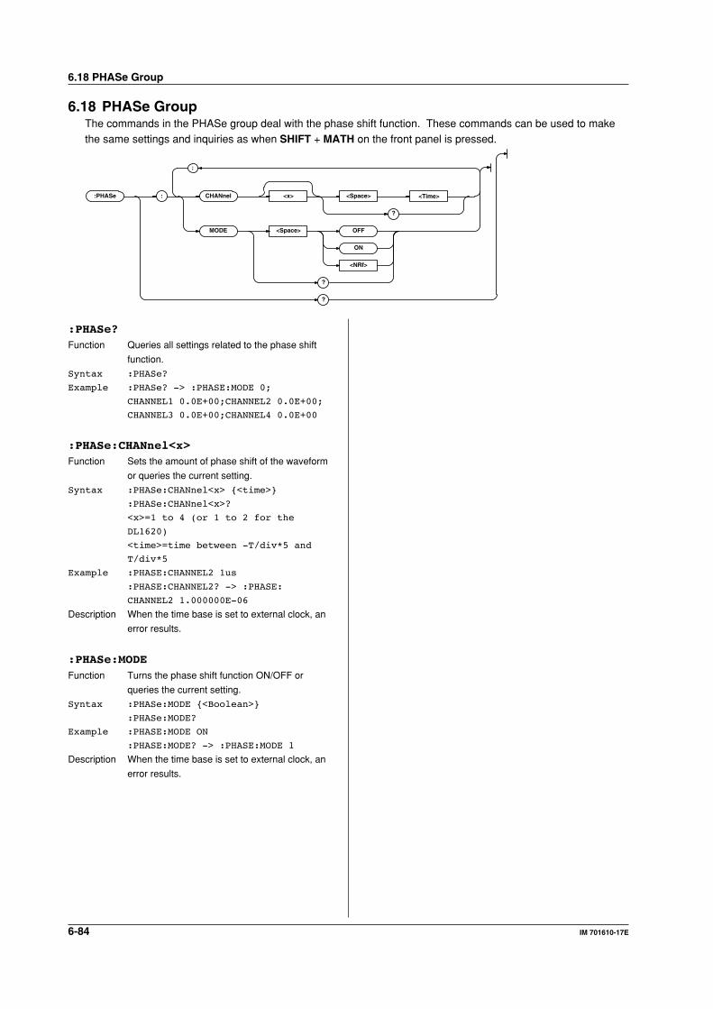
6-84 IM 701610-17E
6.18 PHASe GroupThe commands in the PHASe group deal with the phase shift function. These commands can be used to makethe same settings and inquiries as when SHIFT + MATH on the front panel is pressed.
:PHASe : CHANnel <x> <Space> <Time>
?
MODE <Space> OFF
ON
<NRf>
?
?
;
:PHASe?Function Queries all settings related to the phase shift
function.
Syntax :PHASe?
Example :PHASe? -> :PHASE:MODE 0;
CHANNEL1 0.0E+00;CHANNEL2 0.0E+00;
CHANNEL3 0.0E+00;CHANNEL4 0.0E+00
:PHASe:CHANnel<x>Function Sets the amount of phase shift of the waveform
or queries the current setting.
Syntax :PHASe:CHANnel<x> <time>
:PHASe:CHANnel<x>?
<x>=1 to 4 (or 1 to 2 for the
DL1620)
<time>=time between -T/div*5 and
T/div*5
Example :PHASE:CHANNEL2 1us
:PHASE:CHANNEL2? -> :PHASE:
CHANNEL2 1.000000E-06
Description When the time base is set to external clock, an
error results.
:PHASe:MODEFunction Turns the phase shift function ON/OFF or
queries the current setting.
Syntax :PHASe:MODE <Boolean>
:PHASe:MODE?
Example :PHASE:MODE ON
:PHASE:MODE? -> :PHASE:MODE 1
Description When the time base is set to external clock, an
error results.
6.18 PHASe Group
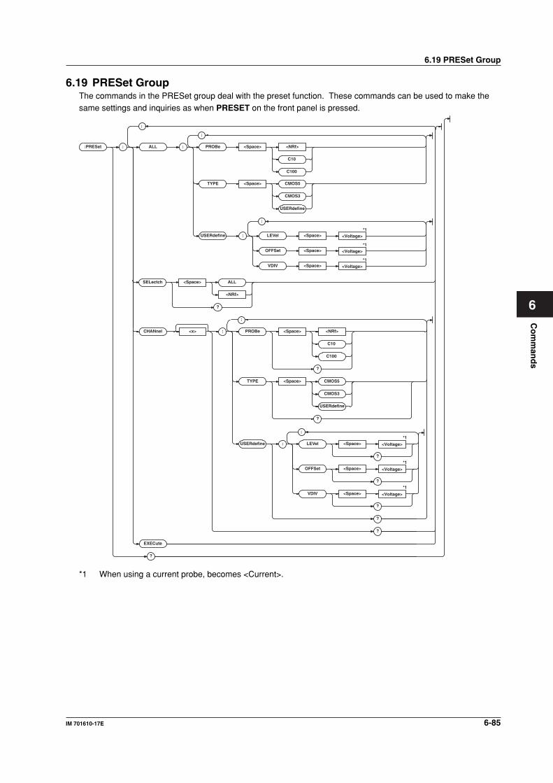
Co
mm
and
s
6-85IM 701610-17E
6
6.19 PRESet GroupThe commands in the PRESet group deal with the preset function. These commands can be used to make thesame settings and inquiries as when PRESET on the front panel is pressed.
:PRESet : ALL : PROBe <Space> <NRf>
TYPE <Space> CMOS5
CMOS3
USERdefine
C10
C100
C10
C100
USERdefine : LEVel <Space>
OFFSet <Space>
VDIV <Space>
CHANnel <x> : PROBe <Space> <NRf>
?
TYPE <Space> CMOS5
CMOS3
USERdefine
?
USERdefine : LEVel <Space>*1
*1
*1
*1
*1
*1
?
OFFSet <Space>
?
VDIV <Space>
?
?
?
EXECute
?
;
<Voltage>
<Voltage>
<Voltage>
<Voltage>
<Voltage>
<Voltage>
;
;
;
;
SELectch <Space> ALL
?
<NRf>
*1 When using a current probe, becomes <Current>.
6.19 PRESet Group
6-86 IM 701610-17E
6.19 PRESet Group
:PRESet?Function Queries all settings related to the preset
function.
Syntax :PRESet?
Example :PRESET -> :PRESET:ALL:TYPE CMOS5;
USERDEFINE:VDIV 50.000E+00;
LEVEL 0.0E+00;
OFFSET 0.0E+00;:PRESET:
ALL:PROBE 10;:PRESET:SELECTCH ALL;
CHANNEL1:TYPE CMOS5;USERDEFINE:
VDIV 50.000E+00;LEVEL 0.0E+00;
OFFSET 0.0E+00;:PRESET:CHANNEL1:
PROBE 10;:PRESET:CHANNEL2:
TYPE CMOS5;USERDEFINE:
VDIV 50.000E+00;LEVEL 0.0E+00;
OFFSET 0.0E+00;:PRESET:CHANNEL2:
PROBE 10;:PRESET:CHANNEL3:
TYPE CMOS5;USERDEFINE:
VDIV 50.000E+00;LEVEL 0.0E+00;
OFFSET 0.0E+00;:PRESET:CHANNEL3:
PROBE 10;:PRESET:CHANNEL4:
TYPE CMOS5;USERDEFINE:
VDIV 50.000E+00;LEVEL 0.0E+00;
OFFSET 0.0E+00;:PRESET:CHANNEL4:
PROBE 10
:PRESet:ALL:PROBeFunction Sets the preset values of the probe attenuation
of all channels.
Syntax :PRESet:ALL:PROBe <NRf>|C10|C100
<NRf>=1,10,100,1000
Example :PRESET:ALL:PROBE 10
:PRESet:ALL:TYPEFunction Sets preset values to all channels.
Syntax :PRESet:ALL:TYPE CMOS5|CMOS3|
USERdefine
Example :PRESET:ALL:TYPE USERDEFINE
:PRESet:ALL:USERdefine:LEVelFunction Sets the preset trigger level of all channels.
Syntax :PRESet:ALL:USERdefine:
LEVel <voltage>
<voltage>=8 div on the screen (0.01
div steps)
Example :PRESET:ALL:USERDEFINE:LEVEL 0V
Description When set to the current probe, sets the
<Current> value.
:PRESet:ALL:USERdefine:OFFSetFunction Sets the preset offset voltage of all channels.
Syntax :PRESet:ALL:USERdefine:
OFFSet <voltage>
<voltage>=See the IM701610-01E
User's Manual.
Example :PRESET:ALL:USERDEFINE:OFFSET 0V
Description When set to the current probe, sets the
<Current> value.
:PRESet:ALL:USERdefine:VDIVFunction Sets the preset V/div value of all channels.
Syntax :PRESet:ALL:USERdefine:
VDIV <voltage>
<voltage>=2 mV to 10 V (when the
probe attenuation is 1:1, See the
IM701610-01E User's Manual.)
Example :PRESET:ALL:USERDEFINE:VDIV 2V
Description When set to the current probe, sets the
<Current> value.
:PRESet:CHANnel<x>?Function Queries the preset information of an arbitrary
channel.
Syntax :PRESet:CHANnel<x>?
<x>=1 to 4 (or 1 to 2 for the DL1620)
Example :PRESET:CHANNEL1? -> :PRESET:
CHANNEL1:TYPE TTL;USERDEFINE:
VDIV 50.000E+00;LEVEL 0.0E+00;
OFFSET 0.0E+00;:PRESET:CHANNEL1:
PROBE 10
:PRESet:CHANnel<x>:PROBeFunction Sets the preset probe attenuation of an arbitrary
channel or queries the current setting.
Syntax :PRESet:CHANnel<x>:PROBe <NRf>
:PRESet:CHANnel<x>:PROBe?
<x>=1 to 4 (or 1 to 2 for the DL1620)
<NRf>=1,10,100,1000
Example :PRESET:CHANNEL1:PROBE 1
:PRESET:CHANNEL1:PROBE? -> :PRESET:
CHANNEL1:PROBE 1
:PRESet:CHANnel<x>:TYPEFunction Sets the preset type to the channel or queries
the current setting.
Syntax :PRESet:CHANnel<x>:TYPE ECL|TTL|
USERdefine|CURRent<y>
:PRESet:CHANnel<x>:TYPE?
<x>=1 to 4 (or 1 to 2 for the DL1620)
<y>=1,2
Example :PRESET:CHANNEL1:TYPE USERDEFINE
:PRESET:CHANNEL1:TYPE? -> :PRESET:
CHANNEL1:TYPE USERDEFINE
Description "CURRent1" is the current probe (700937),
"CURRent2" is the current probe (701930).
6-87IM 701610-17E
Co
mm
and
s
6
:PRESet:CHANnel<x>:USERdefine?Function Queries all preset values when using User
preset.
Syntax :PRESet:CHANnel<x>:USERdefine?
<x>=1 to 4 (or 1 to 2 for the DL1620)
Example :PRESET:CHANNEL1:USERDEFINE? ->
:PRESET:CHANNEL1:USERDEFINE:
VDIV 50.000E+00;LEVEL 0.0E+00;
OFFSET 0.0E+00
:PRESet:CHANnel<x>:USERdefine:LEVelFunction Sets the preset trigger level of the channel or
queries the current setting.
Syntax :PRESet:CHANNEL<x>:USERdefine:
LEVel <voltage>
:PRESet:CHANNEL<x>:USERdefine:
LEVel?
<x>=1 to 4 (or 1 to 2 for the DL1620)
<voltage>=8 div on the screen (0.01
div steps)
Example :PRESET:CHANNEL1:USERDEFINE:
LEVEL 0V
:PRESET:CHANNEL1:USERDEFINE:LEVEL?
-> :PRESET:CHANNEL1:USERDEFINE:
LEVEL 0.000E+00
Description When set to the current probe, queries the
<Current> value.
:PRESet:CHANnel<x>:USERdefine:OFFSetFunction Sets the preset offset voltage of the channel or
queries the current setting.
Syntax :PRESet:CHANNEL<x>:USERdefine:
OFFSet <voltage>
:PRESet:CHANNEL<x>:USERdefine:
OFFSet?
<x>=1 to 4 (or 1 to 2 for the DL1620)
<voltage>=See the IM701610-01E
User's Manual.
Example :PRESET:CHANNEL1:USERDEFINE:
OFFSET 0V
:PRESET:CHANNEL1:USERDEFINE:OFFSET?
-> :PRESET:CHANNEL1:USERDEFINE:
OFFSET 0.000E+00
Description When set to the current probe, queries the
<Current> value.
6.19 PRESet Group`
:PRESet:CHANnel<x>:USERdefine:VDIVFunction Sets the preset V/div value of the channel or
queries the current setting.
Syntax :PRESet:CHANNEL<x>:USERdefine:
VDIV <voltage>
:PRESet:CHANNEL<x>:USERdefine:VDIV?
<x>=1 to 4 (or 1 to 2 for the DL1620)
<voltage>=2 mV to 10 V(when the
probe attenuation is 1:1, See the
IM701610-01E User's Manual.)
Example :PRESET:CHANNEL1:USERDEFINE:VDIV 2V
:PRESET:CHANNEL1:USERDEFINE:VDIV?
-> :PRESET:CHANNEL1:USERDEFINE:
VDIV 2.000E+00
Description When set to the current probe, queries the
<Current> value.
:PRESet:EXECuteFunction Executes preset.
Syntax :PRESet:EXECute
Example :PRESET:EXECUTE
Description Preset the channel which is selected by the
":PRESet:SELectch" command.
:PRESet:SELectchFunction Sets the channel to be preset or queries the
current setting.
Syntax :PRESet:SELectch ALL|<NRf>
:PRESet:SELectch?
<x>=1 to 4 (or 1 to 2 for the DL1620)
Example :PRESET:SELECTCH 1
:PRESET:SELECTCH? -> :PRESET:
SELECTCH 1
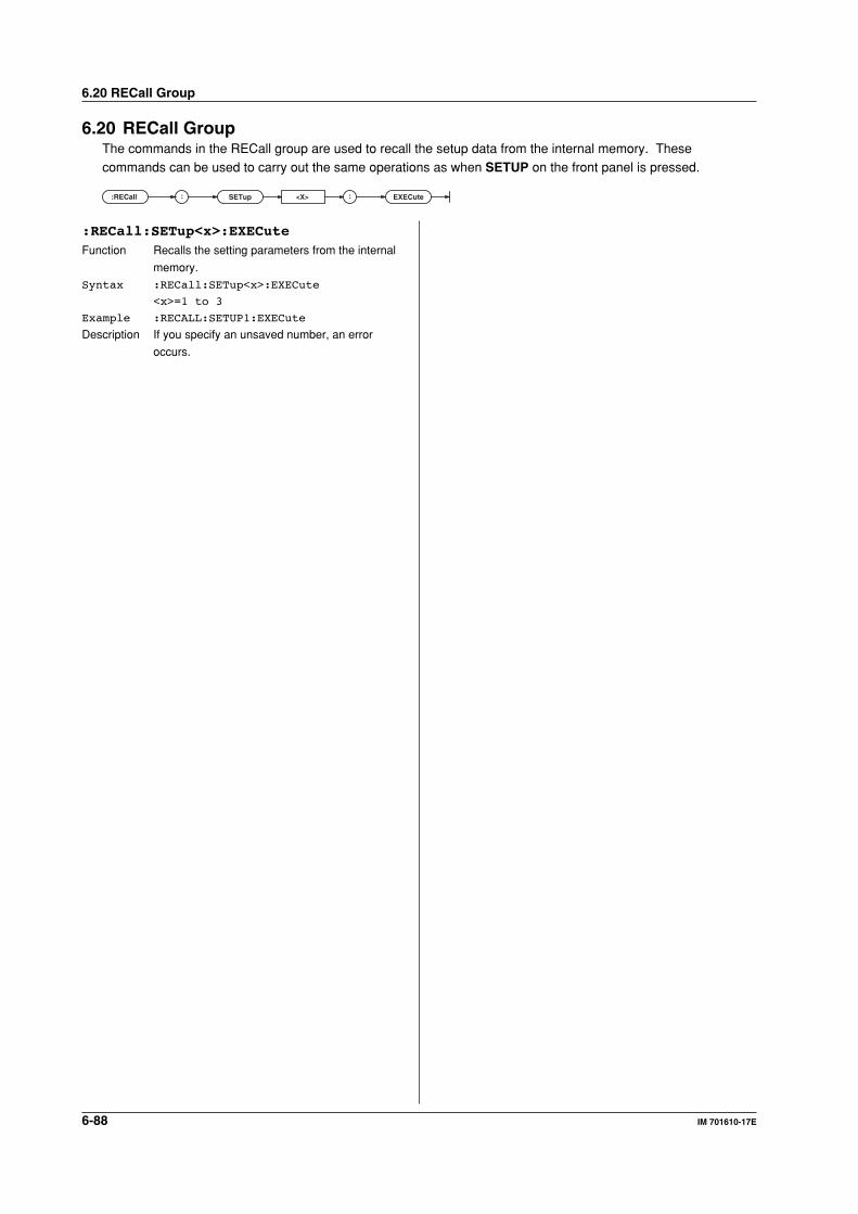
6-88 IM 701610-17E
6.20 RECall GroupThe commands in the RECall group are used to recall the setup data from the internal memory. Thesecommands can be used to carry out the same operations as when SETUP on the front panel is pressed.
:RECall : :SETup <X> EXECute
:RECall:SETup<x>:EXECuteFunction Recalls the setting parameters from the internal
memory.
Syntax :RECall:SETup<x>:EXECute
<x>=1 to 3
Example :RECALL:SETUP1:EXECute
Description If you specify an unsaved number, an error
occurs.
6.20 RECall Group
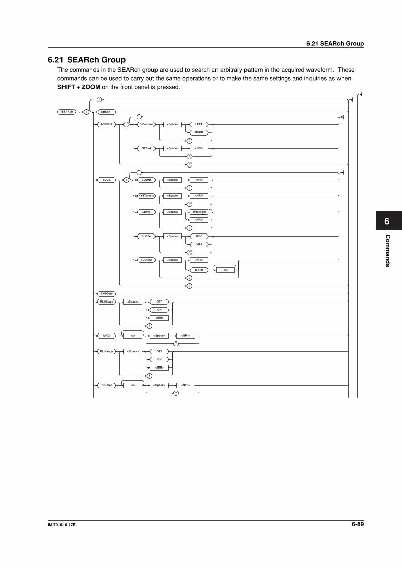
Co
mm
and
s
6-89IM 701610-17E
6
6.21 SEARch Group
6.21 SEARch GroupThe commands in the SEARch group are used to search an arbitrary pattern in the acquired waveform. Thesecommands can be used to carry out the same operations or to make the same settings and inquiries as whenSHIFT + ZOOM on the front panel is pressed.
:SEARch :
EDGE : COUNt <Space> <NRf>
?
HYSTeresis <Space> <NRf>
?
LEVel <Space>
?
SLOPe <Space> RISE
FALL
?
SOURce <Space> <NRf>
MATH <x>
?
?
EXECute
MLINkage <Space> OFF
ON
<NRf>
?
MAG <x> <Space> <NRf>
?
PLINkage <Space> OFF
ON
<NRf>
?
POSition <x> <Space> <NRf>
?
;
;
<NRf>
ASCRoll :
SPEed <Space> <NRf>
?
?
DIRection LEFT
RIGHt
<Space>
?
;
*1
ABORt
<Voltage>
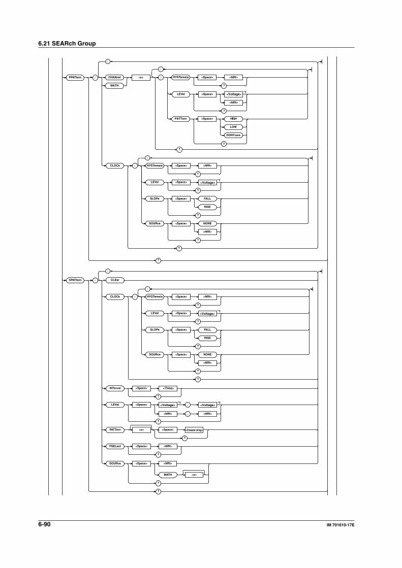
6-90 IM 701610-17E
6.21 SEARch Group
<Space><x>PPATtern : : HYSTeresisCHANnel
MATH
<NRf>
?
PATTern <Space> HIGH
LOW
DONTcare
LEVel <Space>
?
<Voltage>
<NRf>
;
;
?
CLOCk : HYSTeresis <Space> <NRf>
?
LEVel <Space>
?
SLOPe <Space> FALL
RISE
?
SOURce <Space> NONE
<NRf>
?
?
<Voltage>
;
?
SPATtern : CLEar
CLOCk : HYSTeresis <Space> <NRf>
?
LEVel <Space>
?
SLOPe <Space> FALL
RISE
?
SOURce <Space> NONE
<NRf>
?
?
<Voltage>
;
;
INTer val <Space> <Time>
<Voltage> <Voltage>
?
LEVel <Space> ,
?
<NRf> , <NRf>
MATH <x>
?
?
SOURce <Space> <NRf>
<Character string>PA TTern <x> <Space>
?
PSELect <Space> <NRf>
?
?
*1
*1
*1
*1*1
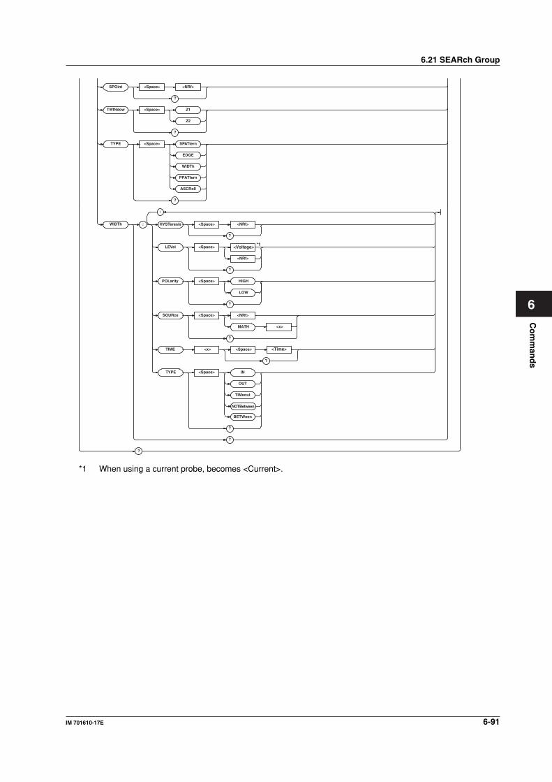
Co
mm
and
s
6-91IM 701610-17E
6
6.21 SEARch Group
SPOint <Space> <NRf>
?
TWINdow <Space> Z1
Z2
?
TYPE <Space> SPATtern
EDGE
WIDTh
PPATtern
ASCRoll
?
?
WIDTh : HYSTeresis <Space> <NRf>
<NRf>
?
TIME <x> <Space> <Time>
?
LEVel <Space>
?
POLarity <Space> HIGH
LOW
MATH
OUT
IN
?
SOURce <Space> <NRf>
<x>
?
<Voltage>
TYPE <Space>
?
TIMeout
BETWeen
;
?
*1
NOTBetween
*1 When using a current probe, becomes <Current>.
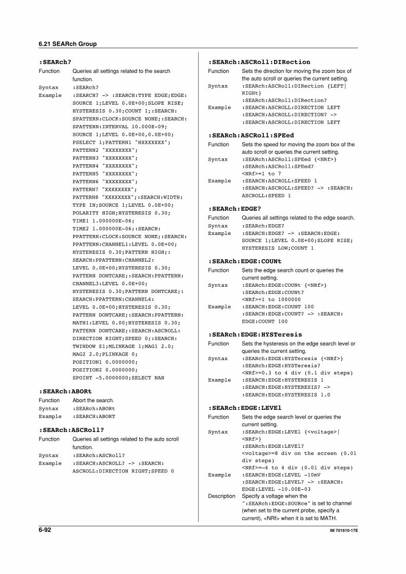
6-92 IM 701610-17E
6.21 SEARch Group
:SEARch?Function Queries all settings related to the search
function.
Syntax :SEARch?
Example :SEARCH? -> :SEARCH:TYPE EDGE;EDGE:
SOURCE 1;LEVEL 0.0E+00;SLOPE RISE;
HYSTERESIS 0.30;COUNT 1;:SEARCH:
SPATTERN:CLOCK:SOURCE NONE;:SEARCH:
SPATTERN:INTERVAL 10.000E-09;
SOURCE 1;LEVEL 0.0E+00,0.0E+00;
PSELECT 1;PATTERN1 "HXXXXXXX";
PATTERN2 "XXXXXXXX";
PATTERN3 "XXXXXXXX";
PATTERN4 "XXXXXXXX";
PATTERN5 "XXXXXXXX";
PATTERN6 "XXXXXXXX";
PATTERN7 "XXXXXXXX";
PATTERN8 "XXXXXXXX";:SEARCH:WIDTH:
TYPE IN;SOURCE 1;LEVEL 0.0E+00;
POLARITY HIGH;HYSTERESIS 0.30;
TIME1 1.000000E-06;
TIME2 1.000000E-06;:SEARCH:
PPATTERN:CLOCK:SOURCE NONE;:SEARCH:
PPATTERN:CHANNEL1:LEVEL 0.0E+00;
HYSTERESIS 0.30;PATTERN HIGH;:
SEARCH:PPATTERN:CHANNEL2:
LEVEL 0.0E+00;HYSTERESIS 0.30;
PATTERN DONTCARE;:SEARCH:PPATTERN:
CHANNEL3:LEVEL 0.0E+00;
HYSTERESIS 0.30;PATTERN DONTCARE;:
SEARCH:PPATTERN:CHANNEL4:
LEVEL 0.0E+00;HYSTERESIS 0.30;
PATTERN DONTCARE;:SEARCH:PPATTERN:
MATH1:LEVEL 0.00;HYSTERESIS 0.30;
PATTERN DONTCARE;:SEARCH:ASCROLL:
DIRECTION RIGHT;SPEED 0;:SEARCH:
TWINDOW Z1;MLINKAGE 1;MAG1 2.0;
MAG2 2.0;PLINKAGE 0;
POSITION1 0.0000000;
POSITION2 0.0000000;
SPOINT -5.0000000;SELECT NAN
:SEARch:ABORtFunction Abort the search.
Syntax :SEARch:ABORt
Example :SEARCH:ABORT
:SEARch:ASCRoll?Function Queries all settings related to the auto scroll
function.
Syntax :SEARch:ASCRoll?
Example :SEARCH:ASCROLL? -> :SEARCH:
ASCROLL:DIRECTION RIGHT;SPEED 0
:SEARch:ASCRoll:DIRectionFunction Sets the direction for moving the zoom box of
the auto scroll or queries the current setting.Syntax :SEARch:ASCRoll:DIRection LEFT|
RIGHt
:SEARch:ASCRoll:DIRection?Example :SEARCH:ASCROLL:DIRECTION LEFT
:SEARCH:ASCROLL:DIRECTION? ->
:SEARCH:ASCROLL:DIRECTION LEFT
:SEARch:ASCRoll:SPEedFunction Sets the speed for moving the zoom box of the
auto scroll or queries the current setting.Syntax :SEARch:ASCRoll:SPEed <NRf>
:SEARch:ASCRoll:SPEed?
<NRf>=1 to 7Example :SEARCH:ASCROLL:SPEED 1
:SEARCH:ASCROLL:SPEED? -> :SEARCH:
ASCROLL:SPEED 1
:SEARch:EDGE?Function Queries all settings related to the edge search.
Syntax :SEARch:EDGE?
Example :SEARCH:EDGE? -> :SEARCH:EDGE:SOURCE 1;LEVEL 0.0E+00;SLOPE RISE;
HYSTERESIS LOW;COUNT 1
:SEARch:EDGE:COUNtFunction Sets the edge search count or queries the
current setting.Syntax :SEARch:EDGE:COUNt <NRf>
:SEARch:EDGE:COUNt?<NRf>=1 to 1000000
Example :SEARCH:EDGE:COUNT 100:SEARCH:EDGE:COUNT? -> :SEARCH:
EDGE:COUNT 100
:SEARch:EDGE:HYSTeresisFunction Sets the hysteresis on the edge search level or
queries the current setting.Syntax :SEARch:EDGE:HYSTeresis <NRf>
:SEARch:EDGE:HYSTeresis?
<NRf>=0.3 to 4 div (0.1 div steps)Example :SEARCH:EDGE:HYSTERESIS 1
:SEARCH:EDGE:HYSTERESIS? ->
:SEARCH:EDGE:HYSTERESIS 1.0
:SEARch:EDGE:LEVElFunction Sets the edge search level or queries the
current setting.Syntax :SEARch:EDGE:LEVEl <voltage>|
<NRf>
:SEARch:EDGE:LEVEl?<voltage>=8 div on the screen (0.01
div steps)<NRf>=–4 to 4 div (0.01 div steps)
Example :SEARCH:EDGE:LEVEL -10mV:SEARCH:EDGE:LEVEL? -> :SEARCH:
EDGE:LEVEL -10.00E-03Description Specify a voltage when the
":SEARch:EDGE:SOURce" is set to channel(when set to the current probe, specify acurrent), <NRf> when it is set to MATH.

6-93IM 701610-17E
Co
mm
and
s
6
6.21 SEARch Group
:SEARch:EDGE:SLOPeFunction Sets the slope of the edge search or queries
the current setting.
Syntax :SEARch:EDGE:SLOPe FALL|RISE
:SEARch:EDGE:SLOPe?
Example :SEARCH:EDGE:SLOPE RISE
:SEARCH:EDGE:SLOPE? -> :SEARCH:
EDGE:SLOPE RISE
:SEARch:EDGE:SOURceFunction Sets the waveform on which to perform the
edge search or queries the current setting.
Syntax :SEARch:EDGE:SOURce <NRf>|MATH<x>
:SEARch:EDGE:SOURce?
<NRf>=1 to 4 (or 1 to 2 for the
DL1620)
<x>=1 or 2 (or 1 for the DL1620)
Example :SEARCH:EDGE:SOURCE MATH1
:SEARCH:EDGE:SOURCE? -> :SEARCH:
EDGE:SOURCE MATH1
:SEARch:EXECuteFunction Executes the search. This is an overlap
command.
Syntax :SEARch:EXECute
Example :SEARCH:EXECUTE
:SEARch:MLINkage (Mag Linkage)Function Turns the link ON/OFF when changing the
zoom rate or queries the current setting.
Syntax :SEARch:MLINkage <Boolean>
:SEARch:MLINkage?
Example :SEARCH:MLINKAGE ON
:SEARCH:MLINKAGE? -> :SEARCH:
MLINKAGE 1
:SEARch:MAG<x>Function Sets the zoom rate of the zoom window or
queries the current setting.
Syntax :SEARch:MAG<x> <NRf>
:SEARch:MAG<x>?
<x>=1 or 2
<NRf>=Up to the point in which 40
points are displayed, see the
IM701610-01E User's Manual.
Example :SEARCH:MAG1 100
:SEARCH:MAG1? -> :SEARCH:MAG1 100
:SEARch:PLINkage (Position Linkage)Function Turns the link ON/OFF when moving the zoom
box or queries the current setting.
Syntax :SEARch:PLINkage <Boolean>
:SEARch:PLINkage?
Example :SEARCH:PLINKAGE OFF
:SEARCH:PLINKAGE? -> :SEARCH:
PLINKAGE 0
:SEARch:POSition<x>Function Sets the zoom box position or queries the
current setting.
Syntax :SEARch:POSition<x> <NRf>
:SEARch:POSition<x>?
<x>=1 or 2
<NRf>=–5 to 5 div (10 div/displayed
record length steps)
Example :SEARCH:POSITION1 2.5
:SEARCH:POSITION1? -> :SEARCH:
POSITION1 2.5000000
:SEARch:PPATtern?Function Queries all settings related to the parallel
pattern search.
Syntax :SEARch:PPATtern?
Example :SEARCH:PPATTERN? -> :SEARCH:
PPATTERN:CLOCK:SOURCE NONE;:SEARCH:
PPATTERN:CHANNEL1:LEVEL 0.0E+00;
HYSTERESIS 0.30;PATTERN HIGH;:
SEARCH:PPATTERN:CHANNEL2:
LEVEL 0.0E+00;HYSTERESIS 0.30;
PATTERN DONTCARE;:SEARCH:PPATTERN:
CHANNEL3:LEVEL 0.0E+00;
HYSTERESIS 0.30;PATTERN DONTCARE;:
SEARCH:PPATTERN:CHANNEL4:
LEVEL 0.0E+00;HYSTERESIS 0.30;
PATTERN DONTCARE;:SEARCH:PPATTERN:
MATH1:LEVEL 0.00;HYSTERESIS 0.30;
PATTERN DONTCARE;:SEARCH:PPATTERN:
MATH2:LEVEL 0.00;HYSTERESIS 0.30;
PATTERN DONTCARE
:SEARch:PPATtern:CHANnel<x>|MATH<x>?Function Queries all settings related to the waveform of
the parallel pattern search.
Syntax :SEARch:PPATtern:CHANnel<x>|
MATH<x>?
The <x> in CHANnel<x>=1 to 4 (or 1
to 2 for the DL1620)
The <x> in MATH<x>=1 or 2 (or 1 for
the DL1620)
Example :SEARCH:PPATTERN:CHANNEL1? ->
:SEARCH:PPATTERN:CHANNEL1:
LEVEL 0.0E+00;HYSTERESIS 0.30;
PATTERN HIGH
6-94 IM 701610-17E
:SEARch:PPATtern:CHANnel<x>|MATH<x>:
HYSTeresisFunction Sets the hysteresis on the waveform on which
to perform the parallel pattern search or queries
the current setting.
Syntax :SEARch:PPATtern:CHANnel<x>|
MATH<x>:HYSTeresis <NRf>
:SEARch:PPATtern:CHANnel<x>|
MATH<x>:HYSTeresis?
The <x> in CHANnel<x>=1 to 4 (or 1
to 2 for the DL1620)
The <x> in MATH<x>=1 or 2 (or 1 for
the DL1620)
<NRf>=0.3 to 4 div (0.1 steps)
Example :SEARCH:PPATTERN:CHANNEL1:
HYSTERESIS 0.3
:SEARCH:PPATTERN:CHANNEL1:
HYSTERESIS? -> :SEARCH:PPATTERN:
CHANNEL1:HYSTERESIS 0.30
:SEARch:PPATtern:CHANnel<x>|MATH<x>:
LEVelFunction Sets the search level on the waveform on which
to perform the parallel pattern search or queries
the current setting.
Syntax :SEARch:PPATtern:CHANnel<x>|
MATH<x>:LEVel <voltage>|<NRf>
:SEARch:PPATtern:CHANnel<x>|
MATH<x>:LEVel?
The <x> in CHANnel<x>=1 to 4 (or 1
to 2 for the DL1620)
The <x> in MATH<x>=1 or 2 (or 1 for
the DL1620)
<voltage>=8 div on the screen (when
the waveform is CH1 to CH4)
<NRf>=-4 to 4 div (0.01 steps when
the waveform is MATH1 or MATH2)
Example :SEARCH:PPATTERN:CHANNEL1:LEVEL 1v
:SEARCH:PPATTERN:CHANNEL1:LEVEL? ->
:SEARCH:PPATTERN:CHANNEL1:
LEVEL 1.000E+00
Description When set to the current probe, sets the
<Current> value or queries the current setting.
:SEARch:PPATtern:CHANnel<x>|MATH<x>:
PATTernFunction Sets the search pattern on the waveform on
which to perform the parallel pattern search or
queries the current setting.
Syntax :SEARch:PPATtern:CHANnel<x>|
MATH<x>:PATTern HIGH|LOW|
DONTcare
:SEARch:PPATtern:CHANnel<x>|
MATH<x>:PATTern?
The <x> in CHANnel<x>=1 to 4 (or 1
to 2 for the DL1620)
The <x> in MATH<x>=1 or 2 (or 1 for
the DL1620)
Example :SEARCH:PPATTERN:CHANNEL1:
PATTERN HIGH
:SEARCH:PPATTERN:CHANNEL1:PATTERN?
-> :SEARCH:PPATTERN:CHANNEL1:
PATTERN HIGH
:SEARch:PPATtern:CLOCk?Function Queries all settings related to the clock channel
of the parallel pattern search.
Syntax :SEARch:PPATtern:CLOCk?
Example :SEARCH:PPATTERN:CLOCK? -> :SEARCH:
PPATTERN:CLOCK:SOURCE 1;
LEVEL 1.000E+00;HYSTERESIS 0.30;
SLOPE RISE
:SEARch:PPATtern:CLOCk:HYSYeresisFunction Sets the hysteresis on the clock channel of the
parallel pattern search or queries the current
setting.
Syntax :SEARch:PPATtern:CLOCk:
HYSYeresis <NRf>
:SEARch:PPATtern:CLOCk:HYSYeresis?
<NRf>=0.3 to 4 div (0.1 steps)
Example :SEARCH:PPATTERN:CLOCK:
HYSTERESIS 4.0
:SEARCH:PPATTERN:CLOCK:HYSTERESIS?
-> :SEARCH:PPATTERN:CLOCK:
HYSTERESIS 4.00
Description An error occurs if ":SEARch:PPATtern:
CLOCk:SOURce" is set to "NONE."
6.21 SEARch Group
6-95IM 701610-17E
Co
mm
and
s
6
6.21 SEARch Group
:SEARch:PPATtern:CLOCk:LEVelFunction Sets the search level of the clock channel of the
parallel pattern search or queries the current
setting.
Syntax :SEARch:PPATtern:CLOCk:
LEVel <voltage>
:SEARch:PPATtern:CLOCk:LEVel?
8 divisions within the screen (0.01
division steps).
Example :SEARCH:PPATTERN:CLOCK:LEVEL 1V
:SEARCH:PPATTERN:CLCOK:LEVEL? ->
:SEARCH:PPATTERN:CLOCK:
LEVEL 1.000E+00
Description • An error occurs if ":SEARch:PPATtern:
CLOCk:SOURce" is set to "NONE."
• When set to the current probe, sets the
<Current> value or queries the current
setting.
:SEARch:PPATtern:CLOCk:SLOPeFunction Sets the slope of the clock channel of the
parallel pattern search or queries the current
setting.
Syntax :SEARch:PPATtern:CLOCk:
SLOPe FALL|RISE
:SEARch:PPATtern:CLOCk:SLOPe?
Example :SEARCH:PPATTERN:CLOCK:SLOPE FALL
:SEARCH:PPATTERN:CLOCK:SLOPE? ->
:SEARCH:PPATTERN:CLOCK:SLOPE FALL
Description An error occurs if ":SEARch:PPATtern:
CLOCk:SOURce" is set to "NONE."
:SEARch:PPATtern:CLOCk:SOURceFunction Sets the waveform used as the clock channel of
the parallel pattern search or queries the
current setting.
Syntax :SEARch:PPATtern:CLOCk:
SOURce NONE|<NRf>
:SEARch:PPATtern:CLOCk:SOURce?
<NRf>=1 to 4 (or 1 to 2 for the
DL1620)
Example :SEARCH:PPATTERN:CLOCK:SOURce 1
:SEARCH:PPATTERN:CLOCK:SOURce? ->
:SEARCH:PPATTERN:CLOCK:SOURCE 1
:SEARch:SELectFunction Queries the storage number of the found
position and the position that is stored in the
specified storage number.
Syntax :SEARch:SELect <NRf>|MAXimum
:SEARch:SELect?
<NRf>=1 to 1000
Example :SEARCH:SELECT 1
:SEARCH:SELECT? -> :SEARCH:
SELECT 2.5000000
Description If no positions are found, "NAN" is returned.
:SEARch:SELect? MAXimumFunction Queries the maximum storage number of the
found positions.
Syntax :SEARch:SELect? MAXimum
Example :SEARCH:SELECT? MAXIMUM -> :SEARCH:
SELECT 100
Description If no positions are found, "NAN" is returned.
:SEARch:SPATtern? (Serial Pattern)Function Queries all settings related to the serial pattern
search.
Syntax :SEARch:SPATtern?
Example :SEARCH:SPATTERN? -> :SEARCH:
SPATTERN:CLOCK:SOURCE NONE;:
SEARCH:SPATTERN:INTERVAL 1.0E-06;
SOURCE 1;LEVEL 0.0E+00;PSELECT 1;
PATTERN1 "HXXXXXXX";
PATTERN2 "XXXXXXXX";
PATTERN3 "XXXXXXXX";
PATTERN4 "XXXXXXXX";
PATTERN5 "XXXXXXXX";
PATTERN6 "XXXXXXXX";
PATTERN7 "XXXXXXXX";
PATTERN8 "XXXXXXXX"
:SEARch:SPATtern:CLEarFunction Clears all search patterns (Don't care).
Syntax :SEARch:SPATtern:CLEar
Example :SEARCH:SPATTERN:CLEAR
:SEARch:SPATtern:CLOCk?Function Queries all settings related to the clock channel.
Syntax :SEARch:SPATtern:CLOCk?
Example :SEARCH:SPATTERN:CLOCK? -> :SEARCH:
SPATTERN:CLOCK:SOURCE 1;
LEVEL 0.0E+00;SLOPE RISE;
HYSTERESIS 0.3
:SEARch:SPATtern:CLOCk:HYSTeresisFunction Sets the hysteresis of the clock channel or
queries the current setting.
Syntax :SEARch:SPATtern:CLOCk:
HYSTeresis <NRf>
:SEARch:SPATtern:CLOCk:HYSTeresis?
<NRf>=0.3 to 4 div (0.1 steps)
Example :SEARCH:SPATTERN:CLOCK:HYSTERESIS 1
:SEARCH:SPATTERN:CLOCK:HYSTERESIS?
-> :SEARCH:SPATTERN:CLOCK:
HYSTERESIS 1.0
Description An error occurs if ":SEAEch:SPATtern:
CLOCk:SOURce" is set to "NONE."
6-96 IM 701610-17E
6.21 SEARch Group
:SEARch:SPATtern:CLOCk:LEVElFunction Sets the level of the clock channel or queries
the current setting.
Syntax :SEARch:SPATtern:CLOCk:
LEVEl <voltage>
:SEARch:SPATtern:CLOCk:LEVEl?
<voltage>=8 div on the screen (0.01
div steps)
Example :SEARCH:SPATTERN:CLOCK:LEVEL -10MV
:SEARCH:SPATTERN:CLOCK:LEVEL? ->
:SEARCH:SPATTERN:CLOCK:
LEVEL -10.00E-03
Description • An error occurs if ":SEAEch:SPATtern:
CLOCk:SOURce" is set to "NONE."
• When set to the current probe, sets the
<Current> value or queries the current
setting.
:SEARch:SPATtern:CLOCk:SLOPeFunction Sets the slope of the clock channel or queries
the current setting.
Syntax :SEARch:SPATtern:CLOCk:
SLOPe FALL|RISE
:SEARch:SPATtern:CLOCk:SLOPe?
Example :SEARCH:SPATTERN:CLOCK:SLOPE RISE
:SEARCH:SPATTERN:CLOCK:SLOPE? ->
:SEARCH:SPATTERN:CLOCK:SLOPE RISE
Description An error occurs if ":SEAEch:SPATtern:
CLOCk:SOURce" is set to "NONE."
:SEARch:SPATtern:CLOCk:SOURceFunction Sets the clock channel source waveform or
queries the current setting.
Syntax :SEARch:SPATtern:CLOCk:
SOURce <NRf>|NONE
:SEARch:SPATtern:CLOCk:SOURce?
<NRf>=1 to 4 (or 1 to 2 for the
DL1620)
Example :SEARCH:SPATTERN:CLOCK:SOURCE 1
:SEARCH:SPATTERN:CLOCK:SOURCE? ->
:SEARCH:SPATTERN:SOURCE 1
:SEARch:SPATtern:INTervalFunction Sets the search interval of the waveform to be
searched or queries the current setting.
Syntax :SEARch:SPATtern:INTerval <time>
:SEARch:SPATtern:INTerval?
<time>=10 ps to 500 s
Example :SEARCH:SPATTERN:INTERVAL 100US
:SEARCH:SPATTERN:INTERVAL? ->
:SEARCH:SPATTERN:
INTERVAL 100.00E-06
:SEARch:SPATtern:LEVelFunction Sets the upper and lower limits of the search
level of the waveform to be searched or queries
the current setting.
Syntax :SEARch:SPATtern:LEVel <voltage>,
<voltage>|<NRf>,NRf>
:SEARch:SPATtern:LEVel?
<voltage>=8 div on the screen (when
the waveform is CH1 to CH4)
<NRf>=–4 to 4 div (0.01 steps when
the waveform is MATH1 or MATH2)
Example :SEARCH:SPATTERN:LEVEL -1V,1V
:SEARCH:SPATTERN:LEVEL? -> :SEARCH:
SPATTERN:LEVEL -1.000E+00,1.000E+00
Description When set to the current probe, sets the
<Current> value or queries the current setting.
:SEARch:SPATtern:PATTern<x>Function Sets the search pattern or queries the current
setting.
Syntax :SEARch:SPATtern:
PATTern<x> <Character string>
:SEARch:SPATtern:PATTern<x>?
<x>=1 to 8
<Character string>=8 characters of
the combination of 'H','L', and 'X'
(The left most character represents
the smallest bit. Total of 8 bits.)
Example :SEARCH:SPATTERN:
PATTERN1 "HLXHLXHL"
:SEARCH:SPATTERN:PATTERN1? ->
:SEARCH:SPATTERN:
PATTERN1 "HLXHLXHL"
Description • <x> represents the 8 bit block number. Thus,
when <x>=1, the left most character
represents bit 0 and the right most character
represents bit 7. The relationship between
<x> and the character string is as follows.
<x>=1: <character string>=bits 0 to 7,
<x>=2: <character string>=bits 8 to 15,
<x>=3: <character string>=bits 16 to 23,
<x>=4: <character string>=bits 24 to 31,
<x>=5: <character string>=bits 32 to 39,
<x>=6: <character string>=bits 40 to 47,
<x>=7: <character string>=bits 48 to 55,
<x>=8: <character string>=bits 56 to 63
• The pattern is assigned the pattern number
that is selected with the ":SEARch:
SPATtern:PSELect" command.
6-97IM 701610-17E
Co
mm
and
s
6
6.21 SEARch Group
:SEARch:SPATtern:PSELect (Pattern
Select)Function Selects the pattern number to which the search
pattern is to be set or queries the current
setting.
Syntax :SEARch:SPATtern:PSELect <NRf>
:SEARch:SPATtern:PSELect?
<x>=1 to 4
Example :SEARCH:SPATTERN:PSELECT 1
Description The values 1 to 4 of <x> correspond to pattern
A to D.
:SEARch:SPATtern:SOURceFunction Sets the waveform on which to perform the
serial pattern search or queries the current
setting.
Syntax :SEARch:SPATtern:SOURce <NRf>|
MATH<x>
:SEARch:SPATtern:SOURce?
<NRf>=1 to 4 (or 1 to 2 for the
DL1620)
<x>=1 or 2 (or 1 for the DL1620)
Example :SEARCH:SPATTERN:SOURCE 1
:SEARCH:SPATTERN:SOURCE? ->
:SEARCH:SPATTERN:SOURCE 1
:SEARch:SPOint (Start Point)Function Sets the start position of the search or queries
the current setting.
Syntax :SEARch:SPOint <NRf>
:SEARch:SPOint?
<NRf>=–5 to 5 div (10 div/displayed
record length steps)
Example :SEARCH:SPOINT 3
:SEARCH:SPOINT? -> :SEARCH:
SPOINT 3.0000000
:SEARch:TWINdow (Target WINdow)Function Sets the zoom window in which to display the
sections that are found or queries the current
setting.
Syntax :SEARch:TWINdow Z1|Z2
:SEARch:TWINdow?
Example :SEARCH:TWINDOW Z1:SEARCH:TWINDOW?
-> :SEARCH:TWINDOW Z1
:SEARch:TYPEFunction Sets the search type or queries the current
setting.
Syntax :SEARch:TYPE SPATtern|EDGE|WIDTh|
PPATtern|ASCRoll
:SEARch:TYPE?
Example :SEARCH:TYPE SPATTERN
:SEARCH:TYPE? -> :SEARCH:
TYPE SPATTERN
:SEARch:WIDTh?Function Queries all settings related to the pulse width
search.
Syntax :SEARch:WIDTh?
Example :SEARCH:WIDTH? -> :SEARCH:WIDTH:
TYPE IN;SOURCE 1;LEVEL 0.0E+00;
POLARITY HIGH;HYSTERESIS 0.30;
TIME1 1.000000E-06;
TIME2 1.000000E-06
:SEARch:WIDTh:HYSTeresisFunction Sets the hysteresis on the pulse width search
level or queries the current setting.
Syntax :SEARch:WIDTh:HYSTeresis <NRf>
:SEARch:WIDTh:HYSTeresis?
<NRf>=0.3 to 4.0div (0.1 steps)
Example :SEARCH:WIDTH:HISTERESIS 0.3
:SEARCH:WIDTH:HISTERESIS? ->
:SEARCH:WIDTH:HYSTERESIS 0.30
:SEARch:WIDTh:LEVelFunction Sets the pulse width search level or queries the
current setting.
Syntax :SEARch:WIDTh:LEVel <voltage>|
<NRf>
:SEARch:WIDTh:LEVel?
<voltage>=8 div on the screen
(0.01div steps)
<NRf>=-4 to 4div(0.01div steps)
Example :SEARCH:WIDTH:LEVEL 1V
:SEARCH:WIDTH:LEVEL? ->
:SEARCH:WIDTH:LEVEL 1.000E+00
Description When set to the current probe, sets the
<Current> value or queries the current setting.
:SEARch:WIDTh:POLarityFunction Sets the pulse width search level’s polarity or
queries the current setting.
Syntax :SEARch:WIDTh:POLarity HIGH|LOW
:SEARch:WIDTh:POLarity?
Example :SEARCH:WIDTH:POLARUTY HIGH
:SEARCH:WIDTH:POLARITY? ->
:SEARCH:WIDTH:POLARITY HIGH
:SEARch:WIDTh:SOURceFunction Sets the search source for the pulse width
search or queries the current setting.
Syntax :SEARch:WIDTh:SOURce <NRf>|
MATH<x>
:SEARch:WIDTh:SOURce?
<NRf>=1 to 4 (or 1 to 2 for the
DL1620)
<x>=1 or 2 (or 1 for the DL1620)
Example :SEARCH:WIDTH:SOURCE 1
:SEARCH:WIDTH:SOURCE? -> :SEARCH:
WIDTH:SOURCE 1
6-98 IM 701610-17E
:SEARch:WIDTh:TIME<x>Function Sets the pulse width when using the pulse width
search or queries the current setting.
Syntax :SEARch:WIDTh:TIME<x> <time>
:SEARch:WIDTh:TIME<x>?
<x>=1 or 2
<time>=20 ps to 500 s
Example :SEARCH:WIDTH:TIME1 20PS
:SEARCH:WIDTH:TIME1? -> :SEARCH:
WIDTH:TIME1 20.0E-12
6.21 SEARch Group/6.22 SNAP Group/6.23 SSTart Group
6.22 SNAP GroupThe SNAP command is used to execute a snapshot. The same function can be performed using SNAPSHOT onthe front panel.
:SNAP
6.23 SSTart GroupThe commands in the SSTart group are used to execute the single start operation. It operates in the same fashionas the single trigger.
:SSTart <Space> <NRf>?
:SEARch:WIDTh:TYPEFunction Sets the search type when using the pulse
width search or queries the current setting.
Syntax :SEARch:WIDTh:TYPE IN|OUT|TIMeout|
BETWeen|NOTBetween
:SEARch:WIDTh:TYPE?
Example :SEARCH:WIDTH:TYPE IN
:SEARCH:WIDTH:TYPE? -> :SEARCH:
WIDTH:TYPE IN
:SNAPFunction Executes a snapshot.
Syntax :SNAP
Example :SNAP
:SSTart?Function Starts the data acquisition with the trigger mode
set to single. If the operation is stopped within
the specified time period, 0 is returned.
Otherwise, 1 is returned.
Syntax :SSTart? <NRf>
<NRf>=1 to 36000 (100 ms resolution
: wait period, START and wait)
0 (START only. No wait.)
-36000 to -1 (100 ms resolution:
wait period, START and wait)
Example :SSTART? 100 -> :SSTART 0
Description • If the specified time period is positive, data
acquisition is started in the SINGLE
TRIGGER mode and waits for the operation
to stop.
• If the specified time period is 0, data
acquisition is started and 0 is returned
without waiting for the operation to stop.
• If the specified time period is negative, the
instrument simply waits for the operation to
stop. Data acquisition is not started.
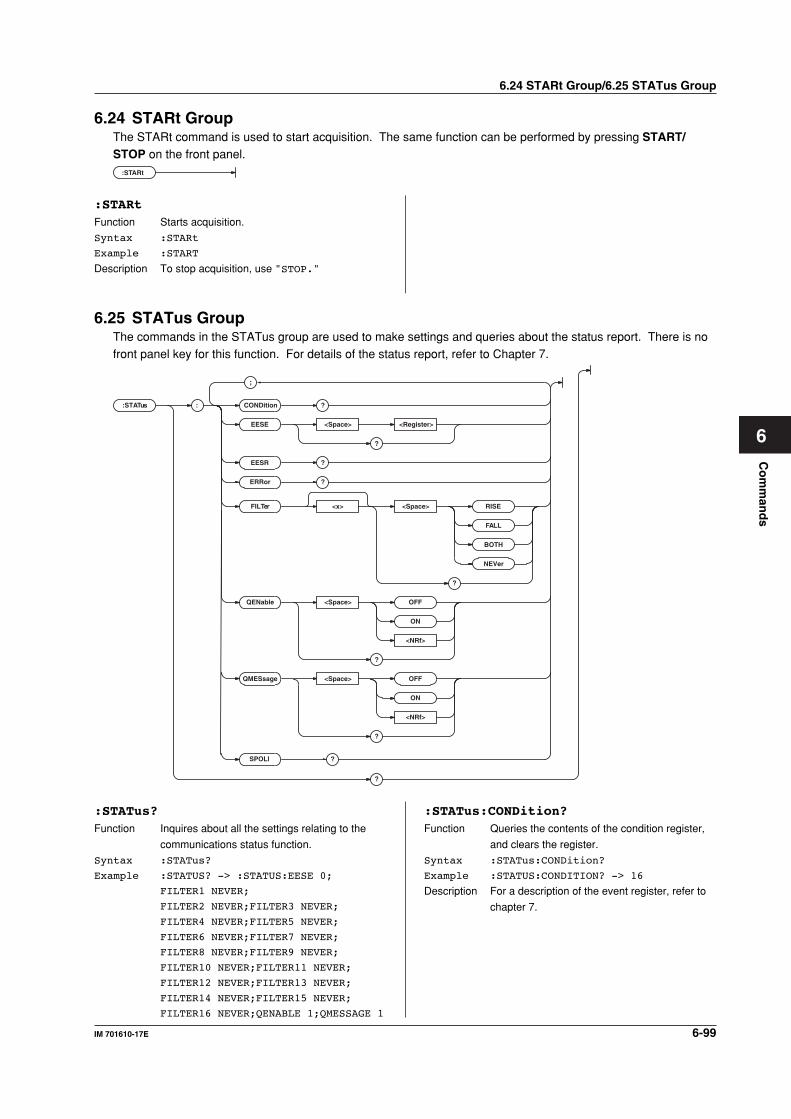
6-99IM 701610-17E
Co
mm
and
s
6
6.24 STARt Group/6.25 STATus Group
6.24 STARt GroupThe STARt command is used to start acquisition. The same function can be performed by pressing START/STOP on the front panel.
:STARt
:STARtFunction Starts acquisition.
Syntax :STARt
Example :START
Description To stop acquisition, use "STOP."
6.25 STATus GroupThe commands in the STATus group are used to make settings and queries about the status report. There is nofront panel key for this function. For details of the status report, refer to Chapter 7.
:STATus : CONDition ?
EESE <Space> <Register>
?
EESR ?
ERRor ?
FILTer <x> <Space> RISE
FALL
BOTH
NEVer
?
QENable <Space> OFF
ON
<NRf>
?
QMESsage <Space> OFF
ON
<NRf>
?
?
SPOLl ?
;
:STATus?Function Inquires about all the settings relating to the
communications status function.
Syntax :STATus?
Example :STATUS? -> :STATUS:EESE 0;
FILTER1 NEVER;
FILTER2 NEVER;FILTER3 NEVER;
FILTER4 NEVER;FILTER5 NEVER;
FILTER6 NEVER;FILTER7 NEVER;
FILTER8 NEVER;FILTER9 NEVER;
FILTER10 NEVER;FILTER11 NEVER;
FILTER12 NEVER;FILTER13 NEVER;
FILTER14 NEVER;FILTER15 NEVER;
FILTER16 NEVER;QENABLE 1;QMESSAGE 1
:STATus:CONDition?Function Queries the contents of the condition register,
and clears the register.
Syntax :STATus:CONDition?
Example :STATUS:CONDITION? -> 16
Description For a description of the event register, refer to
chapter 7.
6-100 IM 701610-17E
:STATus:EESEFunction Sets/queries the extended event enable
register.
Syntax :STATus:EESE <Register>
:STATus:EESE?
<Register>=0 to 65535
Example :STATUS:EESE #B00000000
:STATUS:EESE? -> :STATUS:EESE 0
Description For a description of the event register, refer to
chapter 7.
:STATus:EESR?Function Queries the content of the extended event
register, and clears the register.
Syntax :STATus:EESR?
Example :STATUS:EESR? -> 1
Description For a description of the event register, refer to
chapter 7.
:STATus:ERRor?Function Queries the code and message (at the
beginning of the error queue) of the error which
has occurred.
Syntax :STATus:ERRor?
Example :STATUS:ERROR? ->
113",Undefined header"
:STATus:FILTer<x>Function Sets/queries the transit filter.
Syntax :STATus:FILTer<x> RISE|FALL|BOTH|
NEVer
:STATus:FILTer<x>?
<x>=1 to 16
Example :STATUS:FILTER2 RISE
:STATUS:FILTER2? -> :STATUS:
FILTER2 RISE
Description For a description of the event register, refer to
chapter 7.
:STATus:QENableFunction Selects/queries whether messages other than
errors are stored in the error queue.
Syntax :STATus:QENable <Boolean>
:STATus:QENable?
Example :STATUS:QENABLE ON
:STATUS:QENABLE? -> :STATUS:
QENABLE 1
:STATus:QMESsageFunction Selects/queries whether message content is
appended to responses to "STATus:ERRor?".
Syntax :STATus:QMESsage <Boolean>
:STATus:QMESsage?
Example :STATUS:QMESSAGE ON
:STATUS:QMESSAGE? -> :STATUS:
QMESSAGE 1
:STATus:SPOLl? (Serial Poll)Function Executes the serial polling.
Syntax :STATus:SPOLl?
Example :STATUS:SPOLL? -> 0
Description This is a command for the serial (RS-232)
interface, USB interface, or network interface.
In the case of a GP-IB interface, only an
interface message is returned.
6.25 STATus Group/6.26 STOP Group
6.26 STOP GroupThe STOP command is used to stop acquisition. The same function can be performed using START/STOP onthe front panel.
:STOP
:STOPFunction Stops acquisition.
Syntax :STOP
Example :STOP
Description To start acquisition, use "STARt."
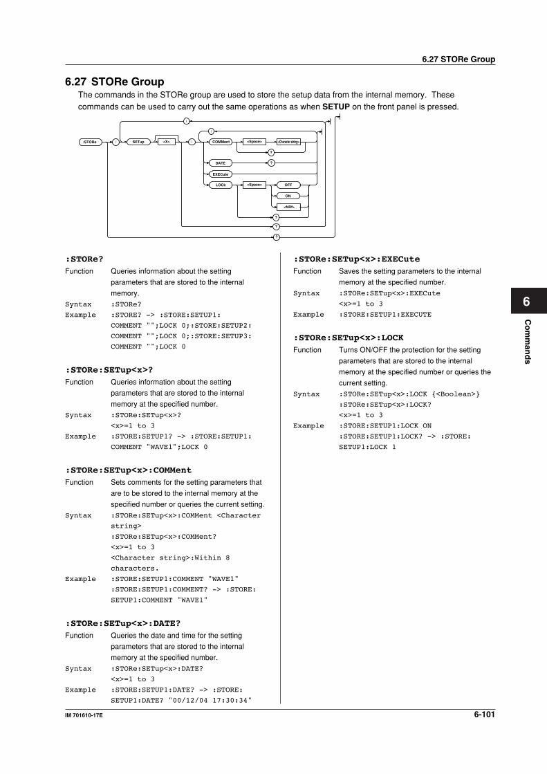
6-101IM 701610-17E
Co
mm
and
s
6
6.27 STORe GroupThe commands in the STORe group are used to store the setup data from the internal memory. Thesecommands can be used to carry out the same operations as when SETUP on the front panel is pressed.
:STORe : SETup : COMMent <Space> <Character string><X>
DATE ?
?
EXECute
LOCk OFF<Space>
<NRf>
ON
?
?
?
;
;
6.27 STORe Group
:STORe?Function Queries information about the setting
parameters that are stored to the internal
memory.
Syntax :STORe?
Example :STORE? -> :STORE:SETUP1:
COMMENT "";LOCK 0;:STORE:SETUP2:
COMMENT "";LOCK 0;:STORE:SETUP3:
COMMENT "";LOCK 0
:STORe:SETup<x>?Function Queries information about the setting
parameters that are stored to the internal
memory at the specified number.
Syntax :STORe:SETup<x>?
<x>=1 to 3
Example :STORE:SETUP1? -> :STORE:SETUP1:
COMMENT "WAVE1";LOCK 0
:STORe:SETup<x>:COMMentFunction Sets comments for the setting parameters that
are to be stored to the internal memory at the
specified number or queries the current setting.
Syntax :STORe:SETup<x>:COMMent <Character
string>
:STORe:SETup<x>:COMMent?
<x>=1 to 3
<Character string>:Within 8
characters.
Example :STORE:SETUP1:COMMENT "WAVE1"
:STORE:SETUP1:COMMENT? -> :STORE:
SETUP1:COMMENT "WAVE1"
:STORe:SETup<x>:DATE?Function Queries the date and time for the setting
parameters that are stored to the internal
memory at the specified number.
Syntax :STORe:SETup<x>:DATE?
<x>=1 to 3
Example :STORE:SETUP1:DATE? -> :STORE:
SETUP1:DATE? "00/12/04 17:30:34"
:STORe:SETup<x>:EXECuteFunction Saves the setting parameters to the internal
memory at the specified number.
Syntax :STORe:SETup<x>:EXECute
<x>=1 to 3
Example :STORE:SETUP1:EXECUTE
:STORe:SETup<x>:LOCKFunction Turns ON/OFF the protection for the setting
parameters that are stored to the internal
memory at the specified number or queries the
current setting.
Syntax :STORe:SETup<x>:LOCK <Boolean>
:STORe:SETup<x>:LOCK?
<x>=1 to 3
Example :STORE:SETUP1:LOCK ON
:STORE:SETUP1:LOCK? -> :STORE:
SETUP1:LOCK 1
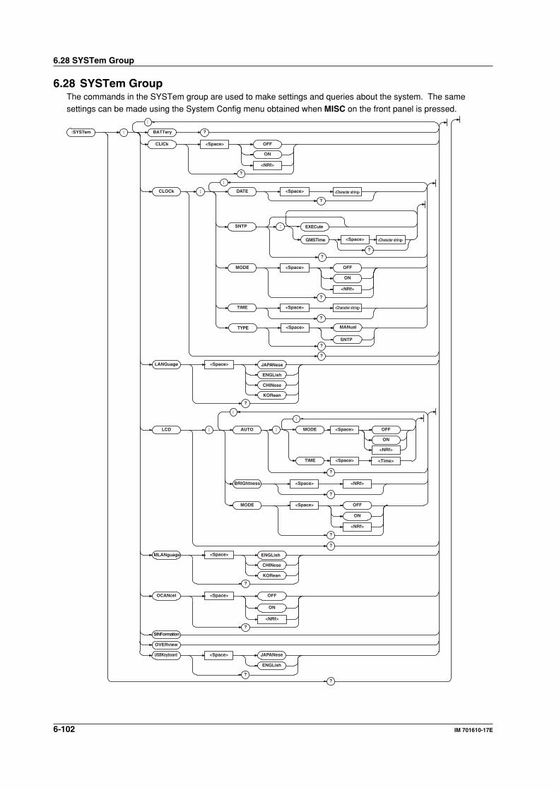
6-102 IM 701610-17E
6.28 SYSTem Group
6.28 SYSTem GroupThe commands in the SYSTem group are used to make settings and queries about the system. The samesettings can be made using the System Config menu obtained when MISC on the front panel is pressed.
:SYSTem :
CLICk <Space> OFF
ON
<NRf>
?
CLOCk : DATE <Space>
?
MODE <Space> OFF
ON
<NRf>
?
TIME <Space>
?
?
SINFormation
LANGuage <Space> JAPANese
ENGLish
CHINese
KORean
?
MLANguage <Space> ENGLish
CHINese
KORean
?
LCD : AUTO
?
BRIGhtness <Space> <NRf>
?
MODE
<Space>
<Space> OFF
ON
<NRf>
?
?
OCANcel <Space> OFF
ON
<NRf>
?
?
;
;
;
BATTery ?
:
;
MODE
TIME
<Space> OFF
ON
<NRf>
OVERview
USBKeyboard <Space> JAPANese
ENGLish
?
GMSTime <Space>
?
EXECute
TYPE <Space>
?
MANual
SNTP
SNTP :
?
<Character string>
<Character string>
<Character string>
<Time>
6-103IM 701610-17E
Co
mm
and
s
6
6.28 SYSTem Group
:SYSTem?Function Queries all system settings.
Syntax :SYSTem?
Example :SYSTEM? -> :SYSTEM:CLOCK:MODE 1;
DATE "2000/06/19";TIME "17:47:17";:
SYSTEM:LANGUAGE JAPANESE;
CLICK 1;LCD:MODE 1;
BRIGHTNESS 4;AUTO:MODE 0;TIME 1;:
SYSTEM:OCANCEL 0;
SYSTEMKEYBOARD JAPANESE
:SYSTem:BATTery?Function Queries the condition of the internal lithium
battery.
Syntax :SYSTem:BATTery?
Example :SYSTEM:BATTERY? -> :SYSTEM:
BATTERY 1
Description "1" is returned if the battery is functioning, and
"0" is returned if the battery has run out.
:SYSTem:CLICkFunction Sets the click sound ON or OFF, or queries the
current setting.
Syntax :SYSTem:CLICk <Boolean>
:SYSTem:CLICk?
Example :SYSTEM:CLICK ON
:SYSTEM:CLICK? -> :SYSTEM:CLICK 1
:SYSTem:CLOCk?Function Queries all settings related to date and time.
Syntax :SYSTem:CLOCk?
Example :SYSTEM:CLOCK? -> :SYSTEM:CLOCK:
MODE 1;TYPE SNTP;DATE "2000/06/19";
TIME "17:47:17";
SNTP:GMTTIME "09:00"
:SYSTem:CLOCk:DATEFunction Sets/queries the date.
Syntax :SYSTem:CLOCK:DATE <Character
string>
:SYSTem:CLOCK:DATE?
<Character string>=YY/MM/DD,refer
to User's Manual IM701610-01E
Example :SYSTEM:CLOCK:DATE "2000/09/30"
:SYSTEM:CLOCK:DATE? -> :SYSTEM:
CLOCK:DATE "2000/09/30"
:SYSTem:CLOCk:MODEFunction Turns the date and time display ON/OFF or
queries the current setting.
Syntax :SYSTem:CLOCk:MODE <Boolean>
:SYSTem:CLOCk:MODE?
Example :SYSTEM:CLOCK:MODE ON
:SYSTEM:CLOCK:MODE? -> :SYSTEM:
CLOCK:MODE 1
:SYSTem:CLOCk:SNTP?Function Queries the SNTP settings.
Syntax :SYSTem:CLOCK:SNTP?
Example :SYSTEM:CLOCK:SNTP? ->
:SYSTEM:CLOCK:SNTP:GMTTime "09:00"
:SYSTem:CLOCk:SNTP:EXECuteFunction Sets/queries date and time setting per SNTP
server.
Syntax :SYSTem:CLOCK:SNTP:EXECute
Example :SYSTem:CLOCK:SNTP:EXECute
:SYSTem:CLOCk:SNTP:GMTTimeFunction Sets/queries the difference from Greenwich
mean time.
Syntax :SYSTem:CLOCK:SNTP:GMTTime
<Character string>
:SYSTem:CLOCK:SNTP:GMTTime?
<Character string>=HH:MM, See the
IM701610-01E User's Manual.
Example :SYSTEM:CLOCK:SNTP:GMTTime "09:00"
:SYSTEM:CLOCK:SNTP:GMTTime? ->
:SYSTEM:CLOCK:SNTP:GMTTime "09:00"
:SYSTem:CLOCk:TIMEFunction Sets the time or queries the current setting.
Syntax :SYSTem:CLOCk:TIME <Character
string>
:SYSTem:CLOCk:TIME?
<Character string>=HH:MM:SS, See
the IM701610-01E User's Manual.
Example :SYSTEM:CLOCK:TIME "14:30:00"
:SYSTEM:CLOCK:TIME? -> :SYSTEM:
CLOCK:TIME "14:30:00"
:SYSTem:CLOCk:TYPEFunction Sets/queries the date and time setting method.
Syntax :SYSTem:CLOCK:TYPE MANual|SNTP
:SYSTem:CLOCK:TYPE?
Example :SYSTEM:CLOCK:TYPE SNTP
:SYSTEM:CLOCK:TYPE? -> :SYSTEM:
CLOCK:TYPE SNTP
:SYSTem:LANGuageFunction Sets/queries the message language.
Syntax :SYSTem:LANGuage ENGLish|JAPANese|
CHINese|KORean
:SYSTem:LANGuage?
Example :SYSTEM:LANGUAGE JAPANESE
:SYSTEM:LANGUAGE? -> :SYSTEM:
LANGUAGE JAPANESE
:SYSTem:LCD?Function Queries all settings related to the LCD monitor.
Syntax :SYSTem:LCD?
Example :SYSTEM:LCD? -> :SYSTEM:LCD:MODE 1;
BRIGHTNESS 1;AUTO:MODE 0;TIME 1
6-104 IM 701610-17E
6.28 SYSTem Group
:SYSTem:LCD:AUTO?Function Queries all settings related to the LCD backlight
auto-off function.
Syntax :SYSTem:LCD:AUTO?
Example :SYSTEM:LCD:AUTO? -> :SYSTEM:LCD:
AUTO:MODE 0;TIME 1
:SYSTem:LCD:AUTO:MODEFunction Turns the LCD backlight ON/OFF or queries the
current setting.
Syntax :SYSTem:LCD:AUTO:MODE <Boolean>
:SYSTem:LCD:AUTO:MODE?
Example :SYSTEM:LCD:AUTO:MODE ON
:SYSTEM:LCD:AUTO:MODE? -> :SYSTEM:
LCD:AUTO:MODE 1
:SYSTem:LCD:AUTO:TIMEFunction Sets the time for the LCD backlight to
automatically turn OFF or queries the current
setting.
Syntax :SYSTem:LCD:AUTO:TIME <NRf>
:SYSTem:LCD:AUTO:TIME?
<NRf>=1 to 60 (s)
Example :SYSTEM:LCD:AUTO:TIME 1
:SYSTEM:LCD:AUTO:TIME? -> :SYSTEM:
LCD:AUTO:TIME 1
:SYSTem:LCD:BRIGhtnessFunction Sets/queries the brightness of the screen.
Syntax :SYSTem:LBRightness<NRf>
:SYSTEM:LBRightness?
<NRf>=1 to 4
Example :SYSTEM:LCD:BRIGTHNESS 2
:SYSTEM:LCD:BRIGTHNESS? -> :SYSTEM:
LCD:BRIGTHNESS 2
:SYSTem:LCD:MODEFunction Turns the LCD backlight ON/OFF or queries the
current setting.
Syntax :SYSTem:LCD:MODE <Boolean>
:SYSTem:LCD:MODE?
Example :SYSTEM:LCD:MODE OFF
:SYSTEM:LCD:MODE? -> :SYSTEM:LCD:
MODE 0
:SYSTem:MLANguageFunction Sets/queries the menu language.
Syntax :SYSTem:MLANguage ENGLish|CHINese|
KORean
:SYSTem:MLANguage?
Example :SYSTEM:MLANGUAGE ENGLISH
:SYSTEM:MLANGUAGE? -> :SYSTEM:
MLANGUAGE ENGLISH
:SYSTem:OCANcel (Offset Cancel)Function Sets whether or not to reflect the offset voltage
to the measured results or the computed results
(ON/OFF) or queries the current setting.
Syntax :SYSTem:OCANcel <Boolean>
:SYSTem:OCANcel?
Example :SYSTEM:OCANCEL ON
:SYSTEM:OCANCEL? -> :SYSTEM:
OCANCEL 0
:SYSTem:OVERviewFunction Displays the system information.
Syntax :SYSTem:OVERview
Example :SYSTEM:OVERVIEW
:SYSTem:SINFormationFunction Displays the setting parameters of the device.
Syntax :SYSTem:SINFormation
Example :SYSTEM:SINFORMATION
SYSTem:USBKeyboardFunction Sets/queries the type of USB keyboard.
Syntax :SYSTem:USBKeyboard ENGLish|
JAPANese
:SYSTem:USBKeyboard?
Example :SYSTEM:USBKEYBOARD JAPANESE
:SYSTEM:USBKEYBOARD? ->
:SYSTEM:USBKEYBOARD JAPANESE
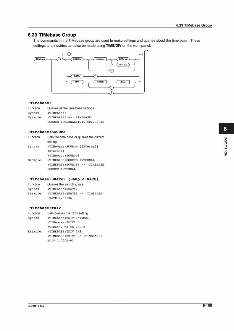
6-105IM 701610-17E
Co
mm
and
s
6
6.29 TIMebase GroupThe commands in the TIMebase group are used to make settings and queries about the time base. Thesesettings and inquiries can also be made using TIME/DIV on the front panel.
:TIMebase : SOURce <Space> EXTernal
INTernal
?
SRATe ?
TDIV <Space> <Time>
?
?
;
6.29 TIMebase Group
:TIMebase?Function Queries all the time base settings.
Syntax :TIMebase?
Example :TIMEBASE? -> :TIMEBASE:
SOURCE INTERNAL;TDIV 500.0E-06
:TIMebase:SOURceFunction Sets the time base or queries the current
setting.
Syntax :TIMebase:SOURce EXTernal|
INTernal
:TIMebase:SOURce?
Example :TIMEBASE:SOURCE INTERNAL
:TIMEBASE:SOURCE? -> :TIMEBASE:
SOURCE INTERNAL
:TIMebase:SRATe? (Sample RATE)Function Queries the sampling rate.
Syntax :TIMebase:SRATe?
Example :TIMEBASE:SRATE? -> :TIMEBASE:
SRATE 1.0E+06
:TIMebase:TDIVFunction Sets/queries the T/div setting.
Syntax :TIMebase:TDIV <Time>
:TIMebase:TDIV?
<Time>=2 ns to 800 s
Example :TIMEBASE:TDIV 1MS
:TIMEBASE:TDIV? -> :TIMEBASE:
TDIV 1.000E-03
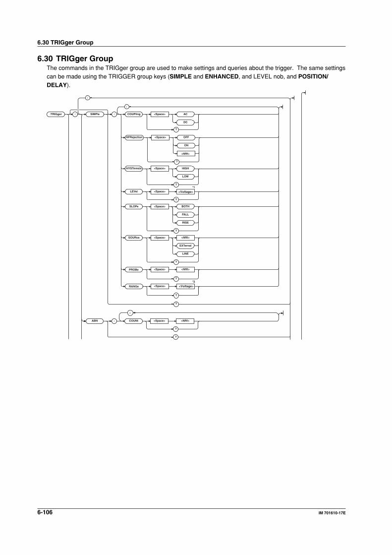
6-106 IM 701610-17E
6.30 TRIGger Group
6.30 TRIGger GroupThe commands in the TRIGger group are used to make settings and queries about the trigger. The same settingscan be made using the TRIGGER group keys (SIMPLE and ENHANCED, and LEVEL nob, and POSITION/DELAY).
:TRIGg er :
;
ABN : COUNt <Space> <NRf>
?
?
;
SIMPle : COUPling <Space> AC
DC
?
HFRejection <Space> OFF
ON
?
HYSTeresis <Space> HIGH
LOW
?
LEVel <Space>*1
*2
?
SLOPe <Space> BOTH
FALL
RISE
?
SOURce <Space> <NRf>
EXTernal
LINE
?
?
<Voltage>
<NRf>
;
PROBe <Space> <NRf>
?
<Voltage>RANGe <Space>
?
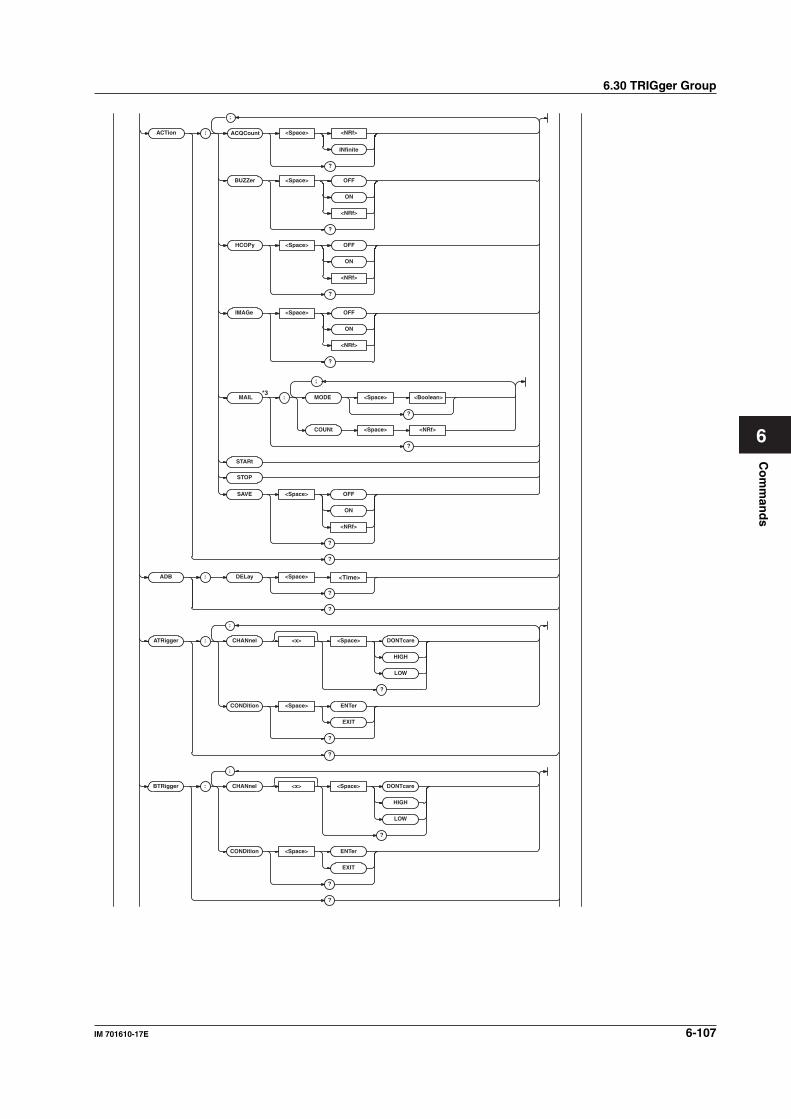
Co
mm
and
s
6-107IM 701610-17E
6
6.30 TRIGger Group
BTRigger : CHANnel <x> <Space> DONTcare
HIGH
LOW
?
CONDition <Space> ENTer
EXIT
?
?
;
STARt
STOP
SAVE <Space> OFF
ON
<NRf>
?
?
ADB : DELay <Space> <Time>
?
?
ATRigger : CHANnel <x> <Space> DONTcare
HIGH
LOW
?
CONDition <Space> ENTer
EXIT
?
?
;
ACTion :
BUZZer <Space> OFF
ON
<NRf>
?
HCOPy <Space> OFF
ON
<NRf>
?
IMAGe <Space> OFF
ON
<NRf>
?
ACQCount <Space>
INfinite
<NRf>
?
;
MAIL : MODE <Space> <Boolean>
?
COUNt <Space> <NRf>
?
;
*3
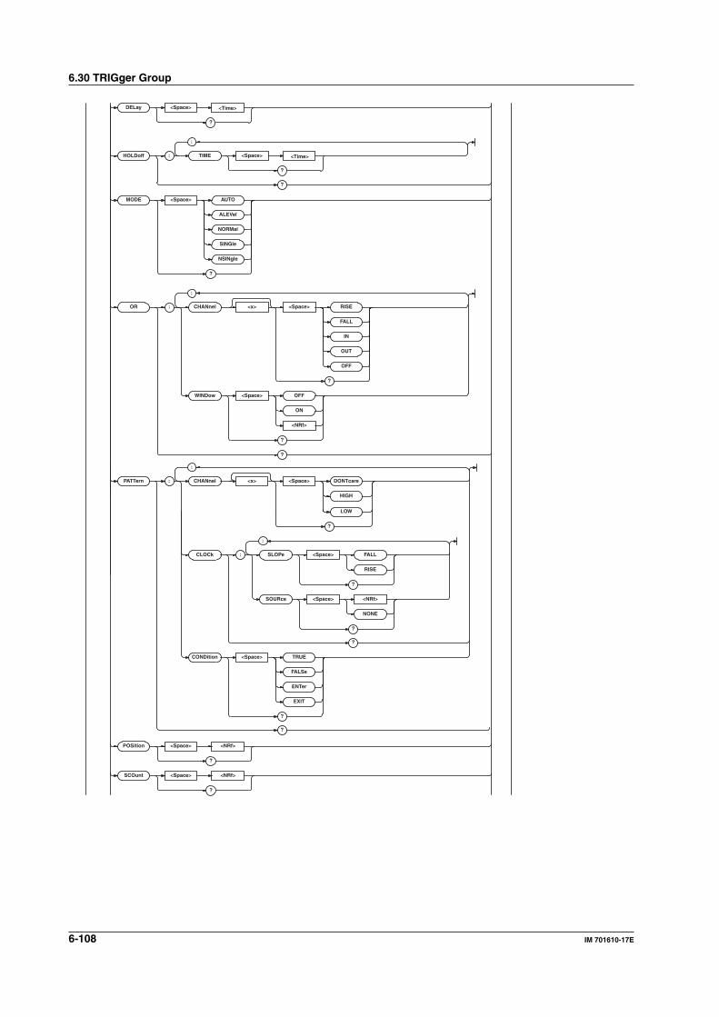
6-108 IM 701610-17E
6.30 TRIGger Group
POSition <Space> <NRf>
?
SCOunt <Space> <NRf>
?
LOW
?
CLOCk : SLOPe <Space> FALL
RISE
?
SOURce <Space> <NRf>
NONE
?
?
CONDition <Space> TRUE
FALSe
ENTer
EXIT
?
?
;
PA TTern : CHANnel <x> <Space> DONTcare
HIGH
;
MODE <Space> AUTO
ALEVel
NORMal
SINGle
NSINgle
?
OR : CHANnel <x> <Space> RISE
FALL
IN
OUT
OFF
?
WINDow <Space> OFF
ON
<NRf>
?
?
;
<Time>HOLDoff : TIME <Space>
?
?
;
<Time>DELay <Space>
?
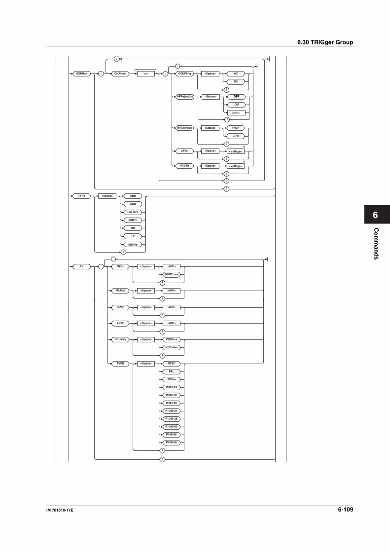
Co
mm
and
s
6-109IM 701610-17E
6
6.30 TRIGger Group
LINE <Space> <NRf>
?
POLarity <Space> POSitive
NEGative
?
TYPE <Space> NTSC
PAL
I1080-24
I1080-50
I1080-60
P1080-24
P1080-25
P1080-60
P480-60
P720-60
SECam
?
?
LEVel <Space> <NRf>
?
SOURce : CHANnel <x> :
OFF
ON
<NRf>
COUPling <Space> AC
DC
?
HFRejection <Space> OFF
?
;
;
HYSTeresis <Space> HIGH
LOW
?
LEVel <Space> <Voltage>
<Voltage>
?
WIDTh <Space>
*1
*1
?
?
?
TYPE <Space> ABN
ADB
PA TTern
WIDTh
OR
TV
SIMPle
?
TV : FIELd <Space> <NRf>
DONTcare
?
FRAMe <Space> <NRf>
?
;
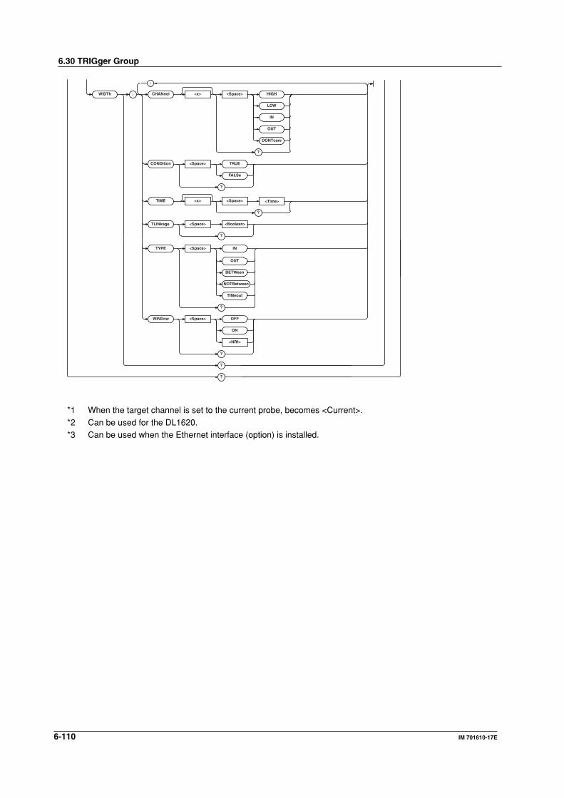
6-110 IM 701610-17E
6.30 TRIGger Group
<Time>
TLINkage <Space> <Boolean>
?
WIDTh : CHANnel <x> <Space> HIGH
LOW
IN
OUT
DONTcare
?
CONDition <Space> TRUE
FALSe
?
TIME <x> <Space>
?
;
OUT
BETWeen
NOTBetween
TIMeout
?
WINDow <Space> OFF
ON
<NRf>
?
?
?
TYPE <Space> IN
*1 When the target channel is set to the current probe, becomes <Current>.
*2 Can be used for the DL1620.*3 Can be used when the Ethernet interface (option) is installed.
6-111IM 701610-17E
Co
mm
and
s
6
:TRIGger?Function Queries all trigger settings.
Syntax :TRIGger?
Example :TRIGGER? -> :TRIGGER:ACTION:
BUZZER 0;SAVE 0;HCOPY 0;IMAGE 0;
ACQCOUNT INFINITE;:TRIGGER:SIMPLE:
SOURCE 1;LEVEL 0.0E+00;SLOPE RISE;
COUPLING DC;HFREJECTION OFF;
HYSTERESIS LOW;PROBE 1;:TRIGGER:
SOURCE:CHANNEL1:LEVEL 0.0E+00;
COUPLING DC;HFREJECTION OFF;
HYSTERESIS LOW;WIDTH 500.000E-03;:
TRIGGER:SOURCE:CHANNEL2:
LEVEL 0.0E+00;COUPLING DC;
HFREJECTION OFF;HYSTERESIS LOW;
WIDTH 50.000E+00;:TRIGGER:SOURCE:
CHANNEL3:LEVEL 0.0E+00;COUPLING DC;
HFREJECTION OFF;HYSTERESIS LOW;
WIDTH 1.000E+00;:TRIGGER:SOURCE:
CHANNEL4:LEVEL 0.0E+00;COUPLING DC;
HFREJECTION OFF;HYSTERESIS LOW;
WIDTH 50.000E+00;:TRIGGER:ABN:
COUNT 1;:TRIGGER:HOLDOFF:
TIME 80.000E-09;:TRIGGER:ADB:
DELAY 1.000E-09;:TRIGGER:
DELAY 0.0E+00;PATTERN:CLOCK:
SOURCE 1;SLOPE RISE;:TRIGGER:
PATTERN:CHANNEL1 HIGH;
CHANNEL2 DONTCARE;
CHANNEL3 DONTCARE;
CHANNEL4 DONTCARE;
CONDITION TRUE;:TRIGGER:
POSITION 50.000;MODE AUTO;WIDTH:
TYPE IN;CHANNEL1 HIGH;
CHANNEL2 HIGH;CHANNEL3 HIGH;
CHANNEL4 HIGH;CONDITION TRUE;
TLINKAGE 0TIME1 1.000E-09;
TIME2 1.000E-09;WINDOW 0;:TRIGGER:
OR:WINDOW 0;CHANNEL1 RISE;
CHANNEL2 OFF;CHANNEL3 OFF;
CHANNEL4 OFF;:TRIGGER:SCOUNT 2;TV:
TYPE NTSC;POLARITY NEGATIVE;
LEVEL 5000000.0;FIELD 1;LINE 5;
FRAME 1;:TRIGGER:TYPE SIMPLE;
ATRIGGER:CHANNEL1 HIGH;
CHANNEL2 DONTCARE;
CHANNEL3 DONTCARE;
CHANNEL4 DONTCARE;CONDITION ENTER;:
TRIGGER:BTRIGGER:CHANNEL1 DONTCARE;
CHANNEL2 HIGH;CHANNEL3 DONTCARE;
CHANNEL4 DONTCARE;CONDITION ENTER
:TRIGger:ABN? (A -> B (n))Function Queries all A -> B (n) trigger settings.
Syntax :TRIGger:ABN?
Example :TRIGGER:ABN? -> :TRIGGER:ABN:
COUNT 1
:TRIGger:ABN:COUNtFunction Sets/queries the number of times the pattern for
the A -> B (n) trigger should become true.
Syntax :TRIGger:ABN:COUNt <NRf>
:TRIGger:ABN:COUNt?
<NRf>=1 to 100000000
Example :TRIGGER:ABN:COUNT 1
:TRIGGER:ABN:COUNT? -> :TRIGGER:
ABN:COUNT 1
:TRIGger:ACTion?Function Queries all settings relating to the action on
trigger.
Syntax :TRIGger:ACTion?
Example :TRIGGER:ACTION? -> :TRIGGER:
ACTION:BUZZER 0;SAVE 0;HCOPY 0;
IMAGE 0;ACQCOUNT INFINITE
:TRIGger:ACTion:ACQCountFunction Sets the number of times to perform the action
for the action-on-trigger or queries the current
setting.
Syntax :TRIGger:ACTion:ACQCount <NRf|
INFinite>
:TRIGger:ACTion:ACQCount?
<NRf>=1 to 65536
Example :TRIGGER:ACTION:ACQCOUNT 10
:TRIGGER:ACTION:ACQCOUNT? ->
:TRIGGER:ACTION:ACQCOUNT 10
:TRIGger:ACTion:BUZZerFunction Sets/queries the ON/OFF condition of the
buzzer at the time of the trigger action.
Syntax :TRIGger:ACTion:BUZZer <Boolean>
:TRIGger:ACTion:BUZZer?
Example :TRIGGER:ACTION:BUZZER ON
:TRIGGER:ACTION:BUZZER? ->
:TRIGGER:ACTION:BUZZER 1
:TRIGger:ACTion:HCOPyFunction Sets/queries whether the screen image data is
output at the time of the trigger action.
Syntax :TRIGger:ACTion:HCOPy <Boolean>
:TRIGger:ACTion:HCOPy?
Example :TRIGGER:ACTION:HCOPY ON
:TRIGGER:ACTION:HCOPY? -> :TRIGGER:
ACTION:HCOPY 1
:TRIGger:ACTion:IMAGeFunction Sets whether or not to save the screen image to
the external storage medium when action is
activated or queries the current setting.
Syntax :TRIGger:ACTion:IMAGe <Boolean>
:TRIGger:ACTion:IMAGe?
Example :TRIGGER:ACTION:IMAGE
ON:TRIGGER:ACTION:IMAGE ->
:TRIGGER:ACTION:IMAGE 1
6.30 TRIGger Group
6-112 IM 701610-17E
:TRIGger:ACTion:MAIL?Function Queries all the setting values for mail reports
sent as an ACTion.
Syntax :TRIGger:ACTion:MAIL?
Example :TRIGGER:ACTION:MAIL:MODE? ->
:TRIGGER:ACTION:MAIL:MODE 0;
COUNT 100
Description Can be used when the Ethernet interface
(option) is installed.
:TRIGger:ACTion:MAIL:COUNtFunction Sets/queries the limit for the number of reports
that are sent as an ACTion.
Syntax :TRIGger:ACTion:MAIL:COUNt <NRf>
:TRIGger:ACTion:MAIL:COUNt?
<NRf>=1 to 1000
Example :TRIGGER:ACTION:MAIL:COUNT 100
:TRIGGER:ACTION:MAIL:COUNT? ->
:TRIGGER:ACTION:MAIL:COUNT 100
Description Can be used when the Ethernet interface
(option) is installed.
:TRIGger:ACTion:MAIL:MODEFunction Sets/queries whether mail reports are sent as
an ACTion.
Syntax :TRIGger:ACTion:MAIL:
MODE <Boolean>
Example :TRIGGER:ACTION:MAIL:MODE OFF
:TRIGGER:ACTION:MAIL:MODE? ->
:TRIGGER:ACTION:MAIL:MODE 0
Description Can be used when the Ethernet interface
(option) is installed.
:TRIGger:ACTion:SAVEFunction Sets/queries whether the waveform data is
saved to the medium at the time of the trigger
action.
Syntax :TRIGger:ACTion:SAVE <Boolean>
:TRIGger:ACTion:SAVE?
Example :TRIGGER:ACTION:SAVE ON
:TRIGGER:ACTION:SAVE? -> :TRIGGER:
ACTION:SAVE 1
:TRIGger:ACTion:STARtFunction Starts action-on-trigger.
Syntax :TRIGger:ACTion:STARt
Example :TRIGGER:ACTION:START
Description Use :TRIGger:ACTION:STOP to abort the
trigger action.
:TRIGger:ACTion:STOPFunction Aborts action-on-trigger.
Syntax :TRIGger:ACTion:STOP
Example :TRIGGER:ACTION:STOP
Description This command only aborts the trigger action. It
does not cancel the settings.
The :TRIGger:ACTION:STARt command can
be used to resume the trigger action.
:TRIGger:ADB? (A Delay B)Function Queries all A Delay B trigger settings.
Syntax :TRIGger:ADB?
Example :TRIGGER:ADB? -> :TRIGGER:ADB:
DELAY 0.000E+00
:TRIGger:ADB:DELayFunction Sets/queries the delay time for pattern B for an
A Delay B trigger.
Syntax :TRIGger:ADB:DELay <Time>
:TRIGger:ADB:DELay?
<Time>=5 ns to 5 s
Example :TRIGGER:ADB:DELAY 1NS
:TRIGGER:ADB:DELAY? -> :TRIGGER:
ADB:DELAY 1.0E-09
:TRIGger:ATRigger?Function Queries all the pattern A settings.
Syntax :TRIGger:ATRigger?
Example :TRIGGER:ATRIGGER? -> :TRIGGER:
ATRIGGER:CHANNEL1 HIGH;
CHANNEL2 DONTCARE;
CHANNEL3 DONTCARE;
CHANNEL4 DONTCARE;CONDITION ENTER
:TRIGger:ATRigger:CHANnel<x>Function Sets/queries the channel condition for pattern
A.
Syntax :TRIGger:ATRigger:
CHANnel<x> DONTcare|HIGH|LOW
:TRIGger:ATRigger:CHANnel<x>?
<x>=1 to 4 (or 1 to 2 for the DL1620)
Example (An example for CH1 is given
below.)
:TRIGGER:ATRIGGER:CHANNEL1 HIGH
:TRIGGER:ATRIGGER:CHANNEL1? ->
:TRIGGER:ATRIGGER:CHANNEL1 HIGH
6.30 TRIGger Group
6-113IM 701610-17E
Co
mm
and
s
6
6.30 TRIGger Group
:TRIGger:ATRigger:CONDitionFunction Sets/queries the conditions under which pattern
A should become true.
Syntax :TRIGger:ATRigger:CONDition ENTer|
EXIT
:TRIGger:ATRigger:CONDition?
Example :TRIGGER:ATRIGGER:CONDITION ENTER
:TRIGGER:ATRIGGER:CONDITION? ->
:TRIGGER:ATRIGGER:CONDITION ENTER
Description This command is valid when the trigger type is
"ABN" or "ADB."
:TRIGger:BTRigger?Function Queries all pattern B settings.
Syntax :TRIGger:BTRigger?
Example :TRIGGER:BTRIGGER? -> :TRIGGER:
BTRIGGER:CHANNEL1 DONTCARE;
CHANNEL2 HIGH;CHANNEL3 DONTCARE;
CHANNEL4 DONTCARE;CONDITION ENTER
:TRIGger:BTRigger:CHANnel<x>Function Sets/queries the channel condition for pattern
B.
Syntax :TRIGger:BTRigger:
CHANnel<x> DONTcare|HIGH|LOW
:TRIGger:BTRigger:CHANnel<x>?
<x>=1 to 4 (or 1 to 2 for the DL1620)
Example (An example for CH1 is given
below.)
:TRIGGER:BTRIGGER:CHANNEL1 HIGH
:TRIGGER:BTRIGGER:CHANNEL1? ->
:TRIGGER:BTRIGGER:CHANNEL1 HIGH
:TRIGger:BTRigger:CONDitionFunction Sets/queries the conditions under which pattern
B becomes true.
Syntax :TRIGger:BTRigger:
CONDition ENTer|EXIT
:TRIGger:BTRigger:CONDition?
Example :TRIGGER:BTRIGGER:CONDITION ENTER
:TRIGGER:BTRIGGER:CONDITION? ->
:TRIGGER:BTRIGGER:CONDITION ENTER
Description This command is valid when the trigger type is
"ABN" or "ADB."
:TRIGger:DELayFunction Sets/queries the trigger delay (time between
trigger point and trigger position).
Syntax :TRIGger:DELay <Time>
:TRIGger:DELay?
<Time>=0 to 4 s (1/sampling rate
steps)
Example :TRIGGER:DELLAY 2US
:TRIGGER:DELAY? -> :TRIGGER:
DELAY 2.00E-06
Description If timebase is external clock, the value is fixed
at 0.
On this oscilloscope, the delay is the time
difference between the trigger point and the
trigger position. You can set/query the trigger
position using the ":TRIGger:POSition"
command.
:TRIGger:HOLDoff?Function Queries all settings related to the hold off.
Syntax :TRIGger:HOLDoff?
Example :TRIGGER:HOLDOFF? -> :TRIGGER:
HOLDOFF:TIME 80.0E-09
:TRIGger:HOLDoff:TIMEFunction Sets the hold off time or queries the current
setting.
Syntax :TRIGger:HOLDoff:TIME <time>
:TRIGger:HOLDoff:TIME?
<time>=80 ns to 10 s
Example :TRIGGER:HOLDOFF:TIME 80NS
:TRIGGER:HOLDOFF:TIME? -> :TRIGGER:
HOLDOFF:TIME 80.0E-09
:TRIGger:MODEFunction Sets the trigger mode or queries the current
setting.
Syntax :TRIGger:MODE AUTO|ALEVel|NORMal|
SINGle|NSINgle
:TRIGger:MODE?
Example :TRIGGER:MODE AUTO
:TRIGGER:MODE? -> :TRIGGER:
MODE AUTO
Description Use the ":TRIGger:SCOunt" command to
query the count when "NSINgle" is selected.
:TRIGger:OR?Function Queries all settings related to the OR trigger.
Syntax :TRIGger:OR?
Example :TRIGGER:OR? -> :TRIGGER:OR:
WINDOW 0;CHANNEL1 OFF;CHANNEL2 OFF;
CHANNEL3 OFF;CHANNEL4 OFF
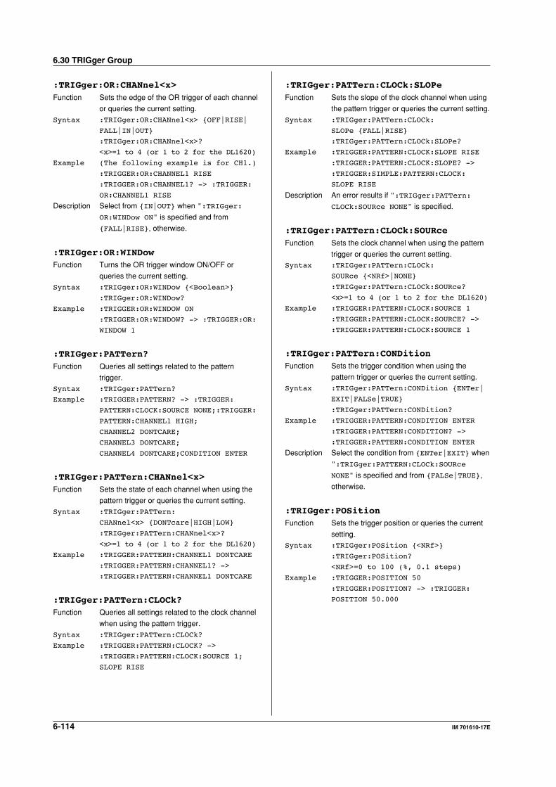
6-114 IM 701610-17E
6.30 TRIGger Group
:TRIGger:OR:CHANnel<x>Function Sets the edge of the OR trigger of each channel
or queries the current setting.
Syntax :TRIGger:OR:CHANnel<x> OFF|RISE|
FALL|IN|OUT
:TRIGger:OR:CHANnel<x>?
<x>=1 to 4 (or 1 to 2 for the DL1620)
Example (The following example is for CH1.)
:TRIGGER:OR:CHANNEL1 RISE
:TRIGGER:OR:CHANNEL1? -> :TRIGGER:
OR:CHANNEL1 RISE
Description Select from IN|OUT when ":TRIGger:
OR:WINDow ON" is specified and from
FALL|RISE, otherwise.
:TRIGger:OR:WINDowFunction Turns the OR trigger window ON/OFF or
queries the current setting.
Syntax :TRIGger:OR:WINDow <Boolean>
:TRIGger:OR:WINDow?
Example :TRIGGER:OR:WINDOW ON
:TRIGGER:OR:WINDOW? -> :TRIGGER:OR:
WINDOW 1
:TRIGger:PATTern?Function Queries all settings related to the pattern
trigger.
Syntax :TRIGger:PATTern?
Example :TRIGGER:PATTERN? -> :TRIGGER:
PATTERN:CLOCK:SOURCE NONE;:TRIGGER:
PATTERN:CHANNEL1 HIGH;
CHANNEL2 DONTCARE;
CHANNEL3 DONTCARE;
CHANNEL4 DONTCARE;CONDITION ENTER
:TRIGger:PATTern:CHANnel<x>Function Sets the state of each channel when using the
pattern trigger or queries the current setting.
Syntax :TRIGger:PATTern:
CHANnel<x> DONTcare|HIGH|LOW
:TRIGger:PATTern:CHANnel<x>?
<x>=1 to 4 (or 1 to 2 for the DL1620)
Example :TRIGGER:PATTERN:CHANNEL1 DONTCARE
:TRIGGER:PATTERN:CHANNEL1? ->
:TRIGGER:PATTERN:CHANNEL1 DONTCARE
:TRIGger:PATTern:CLOCk?Function Queries all settings related to the clock channel
when using the pattern trigger.
Syntax :TRIGger:PATTern:CLOCk?
Example :TRIGGER:PATTERN:CLOCK? ->
:TRIGGER:PATTERN:CLOCK:SOURCE 1;
SLOPE RISE
:TRIGger:PATTern:CLOCk:SLOPeFunction Sets the slope of the clock channel when using
the pattern trigger or queries the current setting.
Syntax :TRIGger:PATTern:CLOCk:
SLOPe FALL|RISE
:TRIGger:PATTern:CLOCk:SLOPe?
Example :TRIGGER:PATTERN:CLOCK:SLOPE RISE
:TRIGGER:PATTERN:CLOCK:SLOPE? ->
:TRIGGER:SIMPLE:PATTERN:CLOCK:
SLOPE RISE
Description An error results if ":TRIGger:PATTern:
CLOCk:SOURce NONE" is specified.
:TRIGger:PATTern:CLOCk:SOURceFunction Sets the clock channel when using the pattern
trigger or queries the current setting.
Syntax :TRIGger:PATTern:CLOCk:
SOURce <NRf>|NONE
:TRIGger:PATTern:CLOCk:SOURce?
<x>=1 to 4 (or 1 to 2 for the DL1620)
Example :TRIGGER:PATTERN:CLOCK:SOURCE 1
:TRIGGER:PATTERN:CLOCK:SOURCE? ->
:TRIGGER:PATTERN:CLOCK:SOURCE 1
:TRIGger:PATTern:CONDitionFunction Sets the trigger condition when using the
pattern trigger or queries the current setting.
Syntax :TRIGger:PATTern:CONDition ENTer|
EXIT|FALSe|TRUE
:TRIGger:PATTern:CONDition?
Example :TRIGGER:PATTERN:CONDITION ENTER
:TRIGGER:PATTERN:CONDITION? ->
:TRIGGER:PATTERN:CONDITION ENTER
Description Select the condition from ENTer|EXIT when
":TRIGger:PATTERN:CLOCk:SOURce
NONE" is specified and from FALSe|TRUE,
otherwise.
:TRIGger:POSitionFunction Sets the trigger position or queries the current
setting.
Syntax :TRIGger:POSition <NRf>
:TRIGger:POSition?
<NRf>=0 to 100 (%, 0.1 steps)
Example :TRIGGER:POSITION 50
:TRIGGER:POSITION? -> :TRIGGER:
POSITION 50.000
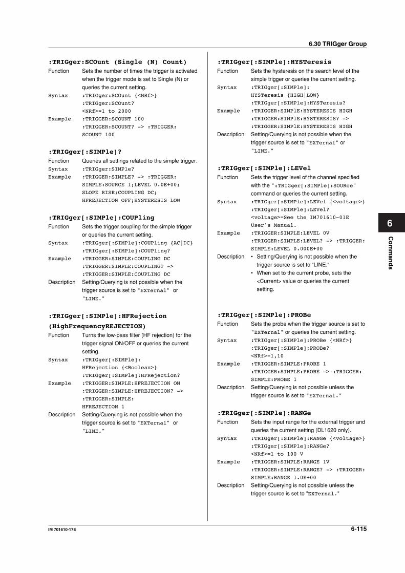
6-115IM 701610-17E
Co
mm
and
s
6
6.30 TRIGger Group
:TRIGger:SCOunt (Single (N) Count)Function Sets the number of times the trigger is activated
when the trigger mode is set to Single (N) or
queries the current setting.
Syntax :TRIGger:SCOunt <NRf>
:TRIGger:SCOunt?
<NRf>=1 to 2000
Example :TRIGGER:SCOUNT 100
:TRIGGER:SCOUNT? -> :TRIGGER:
SCOUNT 100
:TRIGger[:SIMPle]?Function Queries all settings related to the simple trigger.
Syntax :TRIGger:SIMPle?
Example :TRIGGER:SIMPLE? -> :TRIGGER:
SIMPLE:SOURCE 1;LEVEL 0.0E+00;
SLOPE RISE;COUPLING DC;
HFREJECTION OFF;HYSTERESIS LOW
:TRIGger[:SIMPle]:COUPlingFunction Sets the trigger coupling for the simple trigger
or queries the current setting.
Syntax :TRIGger[:SIMPle]:COUPling AC|DC
:TRIGger[:SIMPle]:COUPling?
Example :TRIGGER:SIMPLE:COUPLING DC
:TRIGGER:SIMPLE:COUPLING? ->
:TRIGGER:SIMPLE:COUPLING DC
Description Setting/Querying is not possible when the
trigger source is set to "EXTernal" or
"LINE."
:TRIGger[:SIMPle]:HFRejection
(HighFrequencyREJECTION)Function Turns the low-pass filter (HF rejection) for the
trigger signal ON/OFF or queries the current
setting.
Syntax :TRIGger[:SIMPle]:
HFRejection <Boolean>
:TRIGger[:SIMPle]:HFRejection?
Example :TRIGGER:SIMPLE:HFREJECTION ON
:TRIGGER:SIMPLE:HFREJECTION? ->
:TRIGGER:SIMPLE:
HFREJECTION 1
Description Setting/Querying is not possible when the
trigger source is set to "EXTernal" or
"LINE."
:TRIGger[:SIMPle]:HYSTeresisFunction Sets the hysteresis on the search level of the
simple trigger or queries the current setting.
Syntax :TRIGger[:SIMPle]:
HYSTeresis HIGH|LOW
:TRIGger[:SIMPle]:HYSTeresis?
Example :TRIGGER:SIMPlE:HYSTERESIS HIGH
:TRIGGER:SIMPlE:HYSTERESIS? ->
:TRIGGER:SIMPlE:HYSTERESIS HIGH
Description Setting/Querying is not possible when the
trigger source is set to "EXTernal" or
"LINE."
:TRIGger[:SIMPle]:LEVelFunction Sets the trigger level of the channel specified
with the ":TRIGger[:SIMPle]:SOURce"
command or queries the current setting.
Syntax :TRIGger[:SIMPle]:LEVel <voltage>
:TRIGger[:SIMPle]:LEVel?
<voltage>=See the IM701610-01E
User's Manual.
Example :TRIGGER:SIMPLE:LEVEL 0V
:TRIGGER:SIMPLE:LEVEL? -> :TRIGGER:
SIMPLE:LEVEL 0.000E+00
Description • Setting/Querying is not possible when the
trigger source is set to "LINE."
• When set to the current probe, sets the
<Current> value or queries the current
setting.
:TRIGger[:SIMPle]:PROBeFunction Sets the probe when the trigger source is set to
"EXTernal" or queries the current setting.
Syntax :TRIGger[:SIMPle]:PROBe <NRf>
:TRIGger[:SIMPle]:PROBe?
<NRf>=1,10
Example :TRIGGER:SIMPLE:PROBE 1
:TRIGGER:SIMPLE:PROBE -> :TRIGGER:
SIMPLE:PROBE 1
Description Setting/Querying is not possible unless the
trigger source is set to "EXTernal."
:TRIGger[:SIMPle]:RANGeFunction Sets the input range for the external trigger and
queries the current setting (DL1620 only).
Syntax :TRIGger[:SIMPle]:RANGe <voltage>
:TRIGger[:SIMPle]:RANGe?
<NRf>=1 to 100 V
Example :TRIGGER:SIMPLE:RANGE 1V
:TRIGGER:SIMPLE:RANGE? -> :TRIGGER:
SIMPLE:RANGE 1.0E+00
Description Setting/Querying is not possible unless the
trigger source is set to "EXTernal."

6-116 IM 701610-17E
6.30 TRIGger Group
:TRIGger[:SIMPle]:SLOPeFunction Sets the trigger slope of the channel specified
with the ":TRIGger[:SIMPle]:SOURce"
command or queries the current setting.
Syntax :TRIGger[:SIMPle]:SLOPe BOTH|FALL|
RISE
:TRIGger[:SIMPle]:SLOPe?
Example :TRIGGER:SIMPLE:SLOPE RISE
:TRIGGER:SIMPLE:SLOPE? -> :TRIGGER:
SIMPLE:SLOPE RISE
Description Setting/Querying is not possible when the
trigger source is set to "LINE."
:TRIGger:SIMPle:SOURceFunction Sets the trigger source for the simple trigger or
queries the current setting.
Syntax :TRIGger:SIMPle:SOURce <NRf>|
EXTernal|LINE
:TRIGger:SIMPle:SOURce?
<NRf>=1 to 4 (or 1 to 2 for the
DL1620)
Example :TRIGGER:SIMPLE:SOURCE 1
:TRIGGER:SIMPLE:SOURCE? ->
:TRIGGER:SIMPLE:SOURCE 1
Description Within the :TRIGger:SIMPle series of
commands, "SIMPle" may be omitted except
in the case of the :TRIGger:SIMPle:SOURce
command.
:TRIGger:SOURce?Function Enhanced Queries all settings related to the
trigger source for the enhanced trigger.
Syntax :TRIGger:SOURce?
Example :TRIGGER:SOURCE? -> :TRIGGER:
SOURCE:CHANNEL1:LEVEL 0.0E+00;
COUPLING DC;HFREJECTION OFF;
HYSTERESIS HIGH;CENTER0.0E+00;
WIDTH 2.000E+00;:TRIGGER:SOURCE:
CHANNEL2:LEVEL 0.0E+00;COUPLING DC;
HFREJECTION OFF;HYSTERESIS HIGH;
CENTER 0.0E+00;WIDTH 20.000E+00;:
TRIGGER:SOURCE:CHANNEL3:
LEVEL 0.0E+00;COUPLING DC;
HFREJECTION OFF;HYSTERESIS HIGH;
CENTER 0.0E+00;WIDTH 2.000E+00;:
TRIGGER:SOURCE:CHANNEL4:
LEVEL 0.0E+00;COUPLING DC;
HFREJECTION OFF;HYSTERESIS HIGH;
CENTER 0.0E+00;WIDTH 50.000E+00
:TRIGger:SOURce:CHANnel<x>?Function Queries all settings related to the trigger source
of the enhanced trigger of the specified
channel.
Syntax :TRIGger:SOURce:CHANnel<x>?
<x>=1 to 4 (or 1 to 2 for the DL1620)
Example :TRIGGER:SOURCE:CHANNEL1? ->
:TRIGGER:SOURCE:CHANNEL1:
LEVEL 0.0E+00;COUPLING DC;
HFREJECTION OFF;HYSTERESIS LOW;
CENTER 0.0E+00;WIDTH 2.000E+00
:TRIGger:SOURce:CHANnel<x>:COUPlingFunction Sets the trigger coupling of each channel when
using the enhanced trigger or queries the
current setting.
Syntax :TRIGger:SOURce:CHANnel<x>:
COUPling AC|DC
:TRIGger:SOURce:CHANnel<x>:
COUPling?
<x>=1 to 4 (or 1 to 2 for the DL1620)
Example :TRIGGER:SOURCE:CHANNEL1:COUPLING
DC
:TRIGGER:SOURCE:CHANNEL1:COUPLING?
-> :TRIGGER:SOURCE:CHANNEL1:
COUPLING DC
:TRIGger:SOURce:CHANnel<x>:HFRejection
(HighFrequencyREJECTION)Function Sets the low-pass filter when using the
enhanced trigger or queries the current setting.
Syntax :TRIGger:SOURce:CHANnel<x>:
HFRejection <Boolean>
:TRIGger:SOURce:CHANnel<x>:
HFRejection?
<x>=1 to 4 (or 1 to 2 for the DL1620)
Example :TRIGGER:SOURCE:CHANNEL1:
HFREJECTION ON
:TRIGGER:SOURCE:CHANNEL1:
HFREJECTION? -> :TRIGGER:SOURCE:
CHANNEL1:HFREJECTION 1
:TRIGger:SOURce:CHANnel<x>:HYSTeresisFunction Sets the hysteresis on the search level when
using the enhanced trigger or queries the
current setting.
Syntax :TRIGger:SOURce:CHANnel<x>:
HYSTeresis HIGH|LOW
:TRIGger:SOURce:CHANnel<x>:
HYSTeresis?
<x>=1 to 4 (or 1 to 2 for the DL1620)
Example :TRIGGER:SOURCE:CHANNEL1:
HYSTERESIS HIGH
:TRIGGER:SOURCE:CHANNEL1:
HYSTERESIS? -> :TRIGGER:SOURCE:
CHANNEL1:HYSTERESIS HIGH
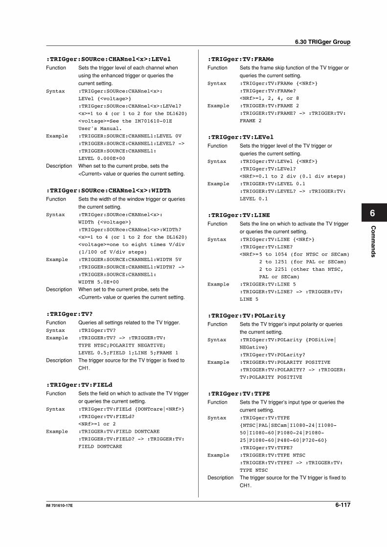
6-117IM 701610-17E
Co
mm
and
s
6
6.30 TRIGger Group
:TRIGger:SOURce:CHANnel<x>:LEVelFunction Sets the trigger level of each channel when
using the enhanced trigger or queries the
current setting.
Syntax :TRIGger:SOURce:CHANnel<x>:
LEVel <voltage>
:TRIGger:SOURce:CHANnel<x>:LEVel?
<x>=1 to 4 (or 1 to 2 for the DL1620)
<voltage>=See the IM701610-01E
User's Manual.
Example :TRIGGER:SOURCE:CHANNEL1:LEVEL 0V
:TRIGGER:SOURCE:CHANNEL1:LEVEL? ->
:TRIGGER:SOURCE:CHANNEL1:
LEVEL 0.000E+00
Description When set to the current probe, sets the
<Current> value or queries the current setting.
:TRIGger:SOURce:CHANnel<x>:WIDThFunction Sets the width of the window trigger or queries
the current setting.
Syntax :TRIGger:SOURce:CHANnel<x>:
WIDTh <voltage>
:TRIGger:SOURce:CHANnel<x>:WIDTh?
<x>=1 to 4 (or 1 to 2 for the DL1620)
<voltage>=one to eight times V/div
(1/100 of V/div steps)
Example :TRIGGER:SOURCE:CHANNEL1:WIDTH 5V
:TRIGGER:SOURCE:CHANNEL1:WIDTH? ->
:TRIGGER:SOURCE:CHANNEL1:
WIDTH 5.0E+00
Description When set to the current probe, sets the
<Current> value or queries the current setting.
:TRIGger:TV?Function Queries all settings related to the TV trigger.
Syntax :TRIGger:TV?
Example :TRIGGER:TV? -> :TRIGGER:TV:
TYPE NTSC;POLARITY NEGATIVE;
LEVEL 0.5;FIELD 1;LINE 5;FRAME 1
Description The trigger source for the TV trigger is fixed to
CH1.
:TRIGger:TV:FIELdFunction Sets the field on which to activate the TV trigger
or queries the current setting.
Syntax :TRIGger:TV:FIELd DONTcare|<NRf>
:TRIGger:TV:FIELd?
<NRf>=1 or 2
Example :TRIGGER:TV:FIELD DONTCARE
:TRIGGER:TV:FIELD? -> :TRIGGER:TV:
FIELD DONTCARE
:TRIGger:TV:FRAMeFunction Sets the frame skip function of the TV trigger or
queries the current setting.
Syntax :TRIGger:TV:FRAMe <NRf>
:TRIGger:TV:FRAMe?
<NRf>=1, 2, 4, or 8
Example :TRIGGER:TV:FRAME 2
:TRIGGER:TV:FRAME? -> :TRIGGER:TV:
FRAME 2
:TRIGger:TV:LEVelFunction Sets the trigger level of the TV trigger or
queries the current setting.
Syntax :TRIGger:TV:LEVel <NRf>
:TRIGger:TV:LEVel?
<NRf>=0.1 to 2 div (0.1 div steps)
Example :TRIGGER:TV:LEVEL 0.1
:TRIGGER:TV:LEVEL? -> :TRIGGER:TV:
LEVEL 0.1
:TRIGger:TV:LINEFunction Sets the line on which to activate the TV trigger
or queries the current setting.
Syntax :TRIGger:TV:LINE <NRf>
:TRIGger:TV:LINE?
<NRf>=5 to 1054 (for NTSC or SECam)
2 to 1251 (for PAL or SECam)
2 to 2251 (other than NTSC,
PAL or SECam)
Example :TRIGGER:TV:LINE 5
:TRIGGER:TV:LINE? -> :TRIGGER:TV:
LINE 5
:TRIGger:TV:POLarityFunction Sets the TV trigger’s input polarity or queries
the current setting.
Syntax :TRIGger:TV:POLarity POSitive|
NEGative
:TRIGger:TV:POLarity?
Example :TRIGGER:TV:POLARITY POSITIVE
:TRIGGER:TV:POLARITY? -> :TRIGGER:
TV:POLARITY POSITIVE
:TRIGger:TV:TYPEFunction Sets the TV trigger’s input type or queries the
current setting.
Syntax :TRIGger:TV:TYPE
NTSC|PAL|SECam|I1080-24|I1080-
50|I1080-60|P1080-24|P1080-
25|P1080-60|P480-60|P720-60
:TRIGger:TV:TYPE?
Example :TRIGGER:TV:TYPE NTSC
:TRIGGER:TV:TYPE? -> :TRIGGER:TV:
TYPE NTSC
Description The trigger source for the TV trigger is fixed to
CH1.
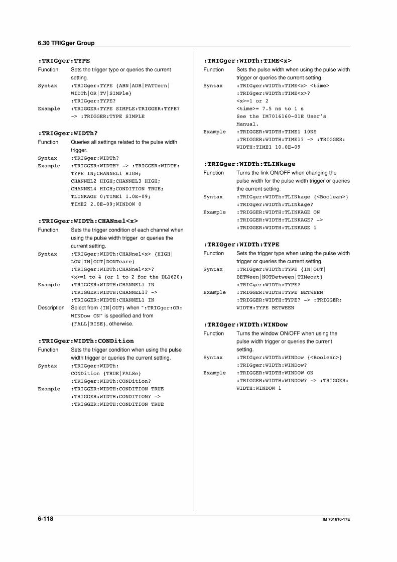
6-118 IM 701610-17E
:TRIGger:TYPEFunction Sets the trigger type or queries the current
setting.
Syntax :TRIGger:TYPE ABN|ADB|PATTern|
WIDTh|OR|TV|SIMPle
:TRIGger:TYPE?
Example :TRIGGER:TYPE SIMPLE:TRIGGER:TYPE?
-> :TRIGGER:TYPE SIMPLE
:TRIGger:WIDTh?Function Queries all settings related to the pulse width
trigger.
Syntax :TRIGger:WIDTh?
Example :TRIGGER:WIDTH? -> :TRIGGER:WIDTH:
TYPE IN;CHANNEL1 HIGH;
CHANNEL2 HIGH;CHANNEL3 HIGH;
CHANNEL4 HIGH;CONDITION TRUE;
TLINKAGE 0;TIME1 1.0E-09;
TIME2 2.0E-09;WINDOW 0
:TRIGger:WIDTh:CHANnel<x>Function Sets the trigger condition of each channel when
using the pulse width trigger or queries the
current setting.
Syntax :TRIGger:WIDTh:CHANnel<x> HIGH|
LOW|IN|OUT|DONTcare
:TRIGger:WIDTh:CHANnel<x>?
<x>=1 to 4 (or 1 to 2 for the DL1620)
Example :TRIGGER:WIDTH:CHANNEL1 IN
:TRIGGER:WIDTH:CHANNEL1? ->
:TRIGGER:WIDTH:CHANNEL1 IN
Description Select from IN|OUT when ":TRIGger:OR:
WINDow ON" is specified and from
FALL|RISE, otherwise.
:TRIGger:WIDTh:CONDitionFunction Sets the trigger condition when using the pulse
width trigger or queries the current setting.
Syntax :TRIGger:WIDTh:
CONDition TRUE|FALSe
:TRIGger:WIDTh:CONDition?
Example :TRIGGER:WIDTH:CONDITION TRUE
:TRIGGER:WIDTH:CONDITION? ->
:TRIGGER:WIDTH:CONDITION TRUE
:TRIGger:WIDTh:TIME<x>Function Sets the pulse width when using the pulse width
trigger or queries the current setting.
Syntax :TRIGger:WIDTh:TIME<x> <time>
:TRIGger:WIDTh:TIME<x>?
<x>=1 or 2
<time>= 7.5 ns to 1 s
See the IM7016160-01E User's
Manual.
Example :TRIGGER:WIDTH:TIME1 10NS
:TRIGGER:WIDTH:TIME1? -> :TRIGGER:
WIDTH:TIME1 10.0E-09
:TRIGger:WIDTh:TLINkageFunction Turns the link ON/OFF when changing the
pulse width for the pulse width trigger or queries
the current setting.
Syntax :TRIGger:WIDTh:TLINkage <Boolean>
:TRIGger:WIDTh:TLINkage?
Example :TRIGGER:WIDTH:TLINKAGE ON
:TRIGGER:WIDTH:TLINKAGE? ->
:TRIGGER:WIDTH:TLINKAGE 1
:TRIGger:WIDTh:TYPEFunction Sets the trigger type when using the pulse width
trigger or queries the current setting.
Syntax :TRIGger:WIDTh:TYPE IN|OUT|
BETWeen|NOTBetween|TIMeout
:TRIGger:WIDTh:TYPE?
Example :TRIGGER:WIDTH:TYPE BETWEEN
:TRIGGER:WIDTH:TYPE? -> :TRIGGER:
WIDTH:TYPE BETWEEN
:TRIGger:WIDTh:WINDowFunction Turns the window ON/OFF when using the
pulse width trigger or queries the current
setting.
Syntax :TRIGger:WIDTh:WINDow <Boolean>
:TRIGger:WIDTh:WINDow?
Example :TRIGGER:WIDTH:WINDOW ON
:TRIGGER:WIDTH:WINDOW? -> :TRIGGER:
WIDTH:WINDOW 1
6.30 TRIGger Group
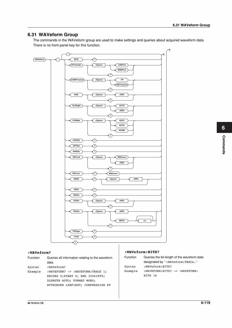
6-119IM 701610-17E
Co
mm
and
s
6
6.31 WAVeform Group
6.31 WAVeform GroupThe commands in the WAVeform group are used to make settings and queries about acquired waveform data.There is no front panel key for this function.
:WAV eform : BITS ?
BYTeorder <Space> LSBFirst
MSBFirst
?
COMPression <Space> PP
DECimation
?
DLENgth <Space>
?
END <Space> <NRf>
?
FORMat <Space> ASCii
BYTE
WORD
?
LENGth ?
OFFSet ?
RANGe ?
RECord
RECord
<Space> MINimum
<NRf>
?
SEND ?
SIGN ?
SRATe ?
STARt <Space> <NRf>
?
<Space> <NRf>
?
TRACe <Space> <NRf>
MATH <x>
?
TRIGg er ?
TYPE ?
?
;
MINimum
AUTO
<NRf>
:WAVeform?Function Queries all information relating to the waveform
data.
Syntax :WAVeform?
Example :WAVEFORM? -> :WAVEFORM:TRACE 1;
RECORD 0;START 0; END 32063999;
DLENGTH AUTO; FORMAT WORD;
BYTEORDER LSBFIRST; COMPRESSION PP
:WAVeform:BITS?Function Queries the bit length of the waveform data
designated by ":WAVeform:TRACe."
Syntax :WAVeform:BITS?
Example :WAVEFORM:BITS? -> :WAVEFORM:
BITS 16
6-120 IM 701610-17E
6.31 WAVeform Group
:WAVeform:BYTeorderFunction Sets/queries the order used to transmit words
consisting of multiple bytes.
Syntax :WAVeform:BYTeorder LSBFirst|
MSBFirst
:WAVeform:BYTeorder?
Example :WAVEFORM:BYTEORDER LSBFIRST
:WAVEFORM:BYTEORDER? -> :WAVEFORM:
BYTEORDER LSBFIRST
:WAVeform:COMPressionFunction Sets the data compression method of the
waveform specified in ."WAVeform:TRACe" or
queries the current setting.
Syntax :WAVeform:COMPression PP|
DECimation
:WAVeform:COMPression
Example :WAVEFORM:COMPRESSION PP
:WAVEFORM:COMPRESSION?->
:WAVEFORM:COMPRESSION PP
:WAVeform:DLENgthFunction Sets the data volume of the waveform specified
in "WAVeform:TRAce" or queries the current
setting.
Syntax :WAVeform:DLENgth AUTO|<NRf>
:WAVeform:DLENgth?
<NRf> = 1000 to 32063999
Example :WAVEFORM:DLENGTH AUTO
:WAVEFORM:DLENGTH?->
:WAVEFORM:DLENGTH AUTO
:WAVeform:ENDFunction Sets/queries the point at which the last item of
data of the waveform designated by
"WAVeform:TRACe" is to be located.
Syntax :WAVeform:END <NRf>
:WAVeform:END?
<NRf>=0 to 32063999
Example· :WAVEFORM:END 1001
:WAVEFORM:END? -> :WAVEFORM:
END 1001
Description You can query total data length (points) with the
":WAVeform:LENgth" command.
:WAVeform:FORMatFunction Sets/queries the format in which the data is to
be transmitted.
Syntax :WAVeform:FORMat ASCii|BYTE|WORD
:WAVeform:FORMat?
Example :WAVEFORM:FORMAT ASCII
:WAVEFORM:FORMAT? -> :WAVEFORM:
FORMAT ASCII
Description For information on the different formats
selected with this command, refer to the
Description section of ":WAVeform:SEND?."
:WAVeform:LENGth?Function Queries the number of records (total number of
data points) in the waveform designated by
"WAVeform:TRACe."
Syntax :WAVeform:LENGth?
Example :WAVEFORM:LENGTH? -> :WAVEFORM:
LENGTH 1002
:WAVeform:OFFSet?Function Queries the offset value that is used when
converting the waveform specified by the
":WAVeform:TRACe" command to physical
values.
Syntax :WAVeform:OFFSet?
Example :WAVEFORM:OFFSET? -> 0.000E+00
Description This offset value is used when converting the
<block data> that are output by the
":WAVeform:SEND?" command to physical
values.
:WAVeform:RANGe?Function Queries the range that is used when converting
the waveform specified by the
":WAVeform:TRACe" command to physical
values.
Syntax :WAVeform:RANGe?
Example :WAVeform:RANGe? -> 5.000E+00
Description This value is used when converting the <block
data> that is output with the
":WAVeform:SEND?" command to physical
values.
:WAVeform:RECordFunction Sets/queries the target record No. for the
WAVeform group.
Syntax :WAVeform:RECord MINimum|<NRf>
:WAVeform:RECord?
<NRf>=0 to –3999 (DL1640)
<NRf>=0 to -15999 (DL1640L)
Example :WAVEFORM:RECORD 0
:WAVEFORM:RECORD? -> :WAVEFORM:
RECORD 0
Description If "MINimum" is specified, the record number is
set to the minimum value. The record numbers
that can be selected vary depending on the
acquisition settings. For details, see the
IM701610-01E User’s Manual.
:WAVeform:RECord? MINimumFunction Queries the smallest record number of the
history of the channel.
Syntax :WAVeform:RECord? MINimum
Example :WAVEFORM:RECORD? MINimum ->
:WAVEFORM:RECORD -1023
6-121IM 701610-17E
Co
mm
and
s
6
6.31 WAVeform Group
:WAVeform:SEND?Function Queries the waveform data specified with the
":WAVeform:TRACe" command.
Syntax :WAVeform:SEND? [<NRf>]
<NRf>=0 to 4000 (DL1620/DL1640)
0 to 16000 (DL1640L)
(depends on the record length
setting)
Example :WAVEFORM:SEND? -> #8 (number of
bytes, 8 digits)(data string) or,
<NRf>,<NRf>, ....
Description The output format of ":WAVeform:SEND?"
varies depending on the ":WAVeform:
FORMat" setting.
(1) When set to "ASCii"
• When the ":WAVeform:TRACe" is 1 to 4
and the linear scaling is OFF, the values
are returned in the following format:
<voltage>, <voltage>, ...<voltage>
• For all other cases, the values are
returned in the form: <NRf>, <NRf>, ...,
<NRf>.
(2) When set to "BYTE" or "WORD"
The values are returned in the <block data>
format.
• The following equation can be used to
convert the values.
Voltage (computed value) =
(Range × data ÷ division*) + offset
*"BYTE": Division=12
"WORD": Division=3072
Query is not possible if
":WAVeform:TRACe" set to MATH1 or
MATH2 and the computation is turned
OFF.
• <NRf> can be omitted. If <NRf> is added,
waveform data are queried <NRf> times
from the record number specified by the
":WAVeform:RECord" command -
<NRf> in order.
:WAVeform:SIGN?Function Queries the presence of the sign, when
querying the waveform specified with
":WAVeform:TRACe" in binary data form.
Syntax :WAVeform:SIGN?
Example :WAVEFORM:SIGN? -> :WAVEFORM:SIGN 1
:WAVeform:SRATe? (Sample RATE)Function Queries the sampling rate for the record
designated by ":WAVeform:RECord".
Syntax :WAVeform:SRATe?
Example :WAVEFORM:SRATE? -> :WAVEFORM:
SRATE 1.0E+09
:WAVeform:STARtFunction Sets/queries the point at which the first item of
data of the waveform designated by
":WAVeform:TRACe" is to be located.
Syntax :WAVeform:STARt <NRf>
:WAVeform:STARt?
<NRf>=0 to 32063999
Example :WAVEFORM:START 0
:WAVEFORM:START? -> :WAVEFORM:
START 0
:WAVeform:TRACeFunction Sets/queries the target waveform for the
WAVeform group.
Syntax :WAVeform:TRACe <NRf>|MATH<x>
:WAVeform:TRACe?
<NRf>=1 to 4 (or 1 to 2 for the
DL1620)
<x>=1 or 2 (or 1 for the DL1620)
Example :WAVEFORM:TRACE 1
:WAVEFORM:TRACE? -> :WAVEFORM:
TRACE 1
:WAVeform:TRIGger?Function Queries the trigger point for the record
designated by ":WAVeform:RECord".
Syntax :WAVeform:TRIGger?
Example :WAVEFORM:TRIGGER? -> :WAVEFORM:
TRIGGER 2000
Description Returns the number of points between the
record start and the trigger position.
:WAVeform:TYPE?Function Queries the acquisition mode for the waveform
specified by the ":WAVeform:TRACe"
command.
Syntax :WAVeform:TYPE?
Example :WAVEFORM:TYPE? -> :WAVEFORM:
TYPE NORMAL
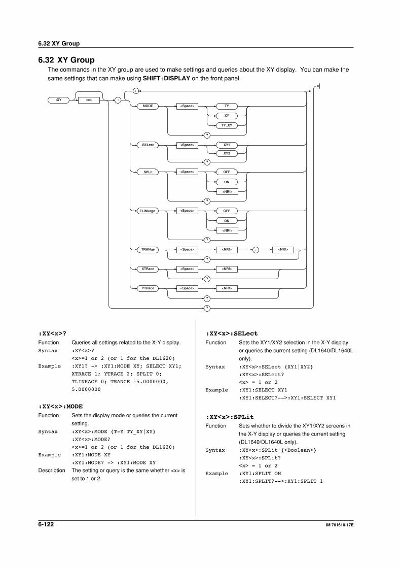
6-122 IM 701610-17E
6.32 XY Group
6.32 XY GroupThe commands in the XY group are used to make settings and queries about the XY display. You can make thesame settings that can make using SHIFT+DISPLAY on the front panel.
:XY <x> :
TRANg e <Space> <NRf> , <NRf>
?
MODE <Space> TY
XY
TY_XY
?
XTRace <Space> <NRf>
?
YTRace <Space> <NRf>
?
?
;
<Space> OFF
?
TLINkage
<Space>
<NRf>
OFF
ON
?
SPLit
SELect <Space>
?
<NRf>
ON
XY1
XY2
:XY<x>?Function Queries all settings related to the X-Y display.
Syntax :XY<x>?
<x>=1 or 2 (or 1 for the DL1620)
Example :XY1? -> :XY1:MODE XY; SELECT XY1;
XTRACE 1; YTRACE 2; SPLIT 0;
TLINKAGE 0; TRANGE -5.0000000,
5.0000000
:XY<x>:MODEFunction Sets the display mode or queries the current
setting.
Syntax :XY<x>:MODE T-Y|TY_XY|XY
:XY<x>:MODE?
<x>=1 or 2 (or 1 for the DL1620)
Example :XY1:MODE XY
:XY1:MODE? -> :XY1:MODE XY
Description The setting or query is the same whether <x> is
set to 1 or 2.
:XY<x>:SELectFunction Sets the XY1/XY2 selection in the X-Y display
or queries the current setting (DL1640/DL1640L
only).
Syntax :XY<x>:SELect XY1|XY2
:XY<x>:SELect?
<x> = 1 or 2
Example :XY1:SELECT XY1
:XY1:SELECT?-->:XY1:SELECT XY1
:XY<x>:SPLitFunction Sets whether to divide the XY1/XY2 screens in
the X-Y display or queries the current setting
(DL1640/DL1640L only).
Syntax :XY<x>:SPLit <Boolean>
:XY<x>:SPLit?
<x> = 1 or 2
Example :XY1:SPLIT ON
:XY1:SPLIT?-->:XY1:SPLIT 1
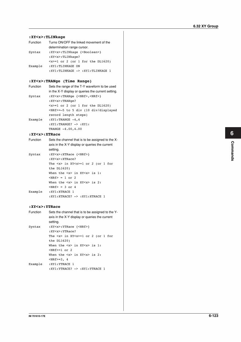
6-123IM 701610-17E
Co
mm
and
s
6
6.32 XY Group
:XY<x>:TLINkageFunction Turns ON/OFF the linked movement of the
determination range cursor.
Syntax :XY<x>:TLINkage <Boolean>
:XY<x>:TLINkage?
<x>=1 or 2 (or 1 for the DL1620)
Example :XY1:TLINKAGE ON
:XY1:TLINKAGE -> :XY1:TLINKAGE 1
:XY<x>:TRANge (Time Range)Function Sets the range of the T-Y waveform to be used
in the X-Y display or queries the current setting.
Syntax :XY<x>:TRANge <NRf>,<NRf>
:XY<x>:TRANge?
<x>=1 or 2 (or 1 for the DL1620)
<NRf>=–5 to 5 div (10 div/displayed
record length steps)
Example :XY1:TRANGE -4,4
:XY1:TRANGE? -> :XY1:
TRANGE -4.00,4.00
:XY<x>:XTRaceFunction Sets the channel that is to be assigned to the X-
axis in the X-Y display or queries the current
setting.
Syntax :XY<x>:XTRace <NRf>
:XY<x>:XTRace?
The <x> in XY<x>=1 or 2 (or 1 for
the DL1620)
When the <x> in XY<x> is 1:
<NRf> = 1 or 2
When the <x> in XY<x> is 2:
<NRf> = 3 or 4
Example :XY1:XTRACE 1
:XY1:XTRACE? -> :XY1:XTRACE 1
:XY<x>:YTRaceFunction Sets the channel that is to be assigned to the Y-
axis in the X-Y display or queries the current
setting.
Syntax :XY<x>:YTRace <NRf>
:XY<x>:YTRace?
The <x> in XY<x>=1 or 2 (or 1 for
the DL1620)
When the <x> in XY<x> is 1:
<NRf>=1 or 2
When the <x> in XY<x> is 2:
<NRf>=3, 4
Example :XY1:YTRACE 1
:XY1:YTRACE? -> :XY1:YTRACE 1
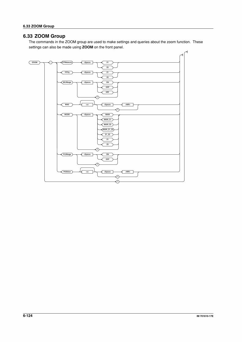
6-124 IM 701610-17E
6.33 ZOOM Group
6.33 ZOOM GroupThe commands in the ZOOM group are used to make settings and queries about the zoom function. Thesesettings can also be made using ZOOM on the front panel.
:ZOOM : FITMeasure <Space> Z1
Z2
FITXy <Space> Z1
Z2
MLINkage <Space> ON
OFF
NRf
?
MAG <x> <Space> <NRf>
?
MODE <Space> MAIN
MAIN_Z1
MAIN_Z2
MAIN_Z1_Z2
Z1_Z2
Z1
Z2
?
PLINkage <Space> ON
OFF
?
POSition <x> <Space> <NRf>
?
?

6-125IM 701610-17E
Co
mm
and
s
6
6.33 ZOOM Group
:ZOOM?Function Queries all waveform zoom settings.
Syntax :ZOOM?
Example :ZOOM? -> :ZOOM:MODE MAIN;
MLINKAGE ON;
MAG1 2.0E+00;MAG2 2.0E+00;
PLINKAGE OFF;POSITION1 0.0000000;
POSITION2 0.0000000
:ZOOM:FITMeasureFunction Changes the range of the automated
measurement of waveform parameters to the
ends of the zoom box.
Syntax :ZOOM:FITMeasure Z1|Z2
:ZOOM:FITMeasure?
Example :ZOOM:FITMEAURE Z1
:ZOOM:FITMEAURE? -> :ZOOM:
FITMEAURE Z1
:ZOOM:FITXyFunction Moves the T-Y waveform range in the X-Y
display to both ends of the zoom box.
Syntax :ZOOM:FITXy Z1|Z2
Example :ZOOM:FITXY Z1
:ZOOM:MLINkage (Mag Linkage)Function Enables/disables/queries zoom ratio linkage.
Syntax :ZOOM:MLINKage <Boolean>
:ZOOM:MLINKage?
Example :ZOOM:MLINKAGE ON
:ZOOM:MLINKAGE? -> :ZOOM:MLINKAGE 1
:ZOOM:MAG<x>Function Sets/queries the zoom ratio.
Syntax :ZOOM:MAG<x> <NRf>
:ZOOM:MAG<x>?
<x>=1, 2
<NRf>=magnification up to 40
points. See the IM701610-01E
User's Manual.
Example :ZOOM:MAG1 2.5
:ZOOM:MAG1? -> :ZOOM:MAG1 2.5
:ZOOM:MODEFunction Sets/queries the zoom display mode.
Syntax :ZOOM:MODE MAIN|MAIN_Z1|MAIN_Z2|
MAIN_Z1_Z2|Z1_Z2|Z1|Z2
:ZOOM:MODE?
Example :ZOOM:MODE MAIN_Z1_Z2
:ZOOM:MODE? -> :ZOOM:
MODE MAIN_Z1_Z2
:ZOOM:PLINkage (Position Linkage)Function Turns the link ON/OFF when moving the zoom
box or queries the current setting.
Syntax :ZOOM:PLINkage <Boolean>
:ZOOM:PLINkage?
Example :ZOOM:PLINKAGE ON
:ZOOM:PLINKAGE? -> :ZOOM:PLINKAGE 1
:ZOOM:POSition<x>Function Sets/queries the zoom box position.
Syntax :ZOOM:POSition<x> <NRf>
:ZOOM:POSition<x>?
<x>=1, 2
<NRf>=-5 to 5 div(in steps of 10
div/display-record-length)
Example :ZOOM:POSITION1 2
:ZOOM:POSITION1? -> :ZOOM:
POSITION1 2.00E+00
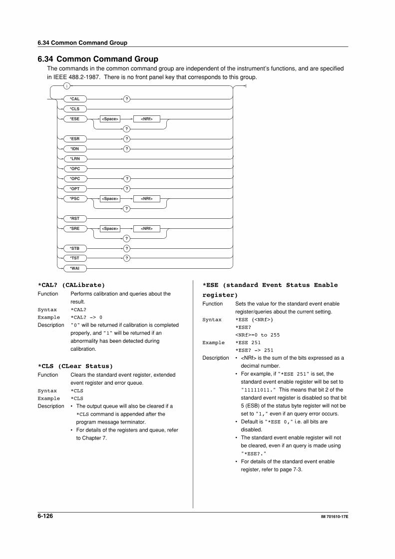
6-126 IM 701610-17E
6.34 Common Command Group
6.34 Common Command GroupThe commands in the common command group are independent of the instrument’s functions, and are specifiedin IEEE 488.2-1987. There is no front panel key that corresponds to this group.
;
*CAL ?
?
<Space> <NRf>*ESE
?
?
?
?
<Space> <NRf>
?
<Space> <NRf>
*CLS
*ESR
?*IDN
*OPC
*OPC
*LRN
*OPT
*PSC
*RST
*SRE
*STB
?*TST
*WAI
?
*CAL? (CALibrate)Function Performs calibration and queries about the
result.
Syntax *CAL?
Example *CAL? -> 0
Description "0" will be returned if calibration is completed
properly, and "1" will be returned if an
abnormality has been detected during
calibration.
*CLS (CLear Status)Function Clears the standard event register, extended
event register and error queue.
Syntax *CLS
Example *CLS
Description • The output queue will also be cleared if a
*CLS command is appended after the
program message terminator.
• For details of the registers and queue, refer
to Chapter 7.
*ESE (standard Event Status Enable
register)Function Sets the value for the standard event enable
register/queries about the current setting.
Syntax *ESE <NRf>
*ESE?
<NRf>=0 to 255
Example *ESE 251
*ESE? -> 251
Description • <NRf> is the sum of the bits expressed as a
decimal number.
• For example, if "*ESE 251" is set, the
standard event enable register will be set to
"11111011." This means that bit 2 of the
standard event register is disabled so that bit
5 (ESB) of the status byte register will not be
set to "1," even if an query error occurs.
• Default is "*ESE 0," i.e. all bits are
disabled.
• The standard event enable register will not
be cleared, even if an query is made using
"*ESE?."
• For details of the standard event enable
register, refer to page 7-3.
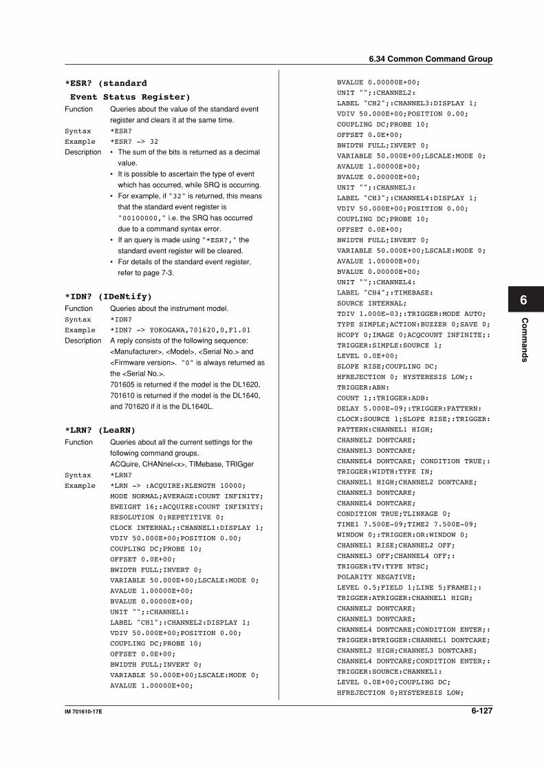
6-127IM 701610-17E
Co
mm
and
s
6
6.34 Common Command Group
*ESR? (standard
Event Status Register)Function Queries about the value of the standard event
register and clears it at the same time.
Syntax *ESR?
Example *ESR? -> 32
Description • The sum of the bits is returned as a decimal
value.
• It is possible to ascertain the type of event
which has occurred, while SRQ is occurring.
• For example, if "32" is returned, this means
that the standard event register is
"00100000," i.e. the SRQ has occurred
due to a command syntax error.
• If an query is made using "*ESR?," the
standard event register will be cleared.
• For details of the standard event register,
refer to page 7-3.
*IDN? (IDeNtify)Function Queries about the instrument model.
Syntax *IDN?
Example *IDN? -> YOKOGAWA,701620,0,F1.01
Description A reply consists of the following sequence:
<Manufacturer>, <Model>, <Serial No.> and
<Firmware version>. "0" is always returned as
the <Serial No.>.
701605 is returned if the model is the DL1620,
701610 is returned if the model is the DL1640,
and 701620 if it is the DL1640L.
*LRN? (LeaRN)Function Queries about all the current settings for the
following command groups.
ACQuire, CHANnel<x>, TIMebase, TRIGger
Syntax *LRN?
Example *LRN -> :ACQUIRE:RLENGTH 10000;
MODE NORMAL;AVERAGE:COUNT INFINITY;
EWEIGHT 16;:ACQUIRE:COUNT INFINITY;
RESOLUTION 0;REPETITIVE 0;
CLOCK INTERNAL;:CHANNEL1:DISPLAY 1;
VDIV 50.000E+00;POSITION 0.00;
COUPLING DC;PROBE 10;
OFFSET 0.0E+00;
BWIDTH FULL;INVERT 0;
VARIABLE 50.000E+00;LSCALE:MODE 0;
AVALUE 1.00000E+00;
BVALUE 0.00000E+00;
UNIT "";:CHANNEL1:
LABEL "CH1";:CHANNEL2:DISPLAY 1;
VDIV 50.000E+00;POSITION 0.00;
COUPLING DC;PROBE 10;
OFFSET 0.0E+00;
BWIDTH FULL;INVERT 0;
VARIABLE 50.000E+00;LSCALE:MODE 0;
AVALUE 1.00000E+00;
BVALUE 0.00000E+00;
UNIT "";:CHANNEL2:
LABEL "CH2";:CHANNEL3:DISPLAY 1;
VDIV 50.000E+00;POSITION 0.00;
COUPLING DC;PROBE 10;
OFFSET 0.0E+00;
BWIDTH FULL;INVERT 0;
VARIABLE 50.000E+00;LSCALE:MODE 0;
AVALUE 1.00000E+00;
BVALUE 0.00000E+00;
UNIT "";:CHANNEL3:
LABEL "CH3";:CHANNEL4:DISPLAY 1;
VDIV 50.000E+00;POSITION 0.00;
COUPLING DC;PROBE 10;
OFFSET 0.0E+00;
BWIDTH FULL;INVERT 0;
VARIABLE 50.000E+00;LSCALE:MODE 0;
AVALUE 1.00000E+00;
BVALUE 0.00000E+00;
UNIT "";:CHANNEL4:
LABEL "CH4";:TIMEBASE:
SOURCE INTERNAL;
TDIV 1.000E-03;:TRIGGER:MODE AUTO;
TYPE SIMPLE;ACTION:BUZZER 0;SAVE 0;
HCOPY 0;IMAGE 0;ACQCOUNT INFINITE;:
TRIGGER:SIMPLE:SOURCE 1;
LEVEL 0.0E+00;
SLOPE RISE;COUPLING DC;
HFREJECTION 0; HYSTERESIS LOW;:
TRIGGER:ABN:
COUNT 1;:TRIGGER:ADB:
DELAY 5.000E-09;:TRIGGER:PATTERN:
CLOCK:SOURCE 1;SLOPE RISE;:TRIGGER:
PATTERN:CHANNEL1 HIGH;
CHANNEL2 DONTCARE;
CHANNEL3 DONTCARE;
CHANNEL4 DONTCARE; CONDITION TRUE;:
TRIGGER:WIDTH:TYPE IN;
CHANNEL1 HIGH;CHANNEL2 DONTCARE;
CHANNEL3 DONTCARE;
CHANNEL4 DONTCARE;
CONDITION TRUE;TLINKAGE 0;
TIME1 7.500E-09;TIME2 7.500E-09;
WINDOW 0;:TRIGGER:OR:WINDOW 0;
CHANNEL1 RISE;CHANNEL2 OFF;
CHANNEL3 OFF;CHANNEL4 OFF;:
TRIGGER:TV:TYPE NTSC;
POLARITY NEGATIVE;
LEVEL 0.5;FIELD 1;LINE 5;FRAME1;:
TRIGGER:ATRIGGER:CHANNEL1 HIGH;
CHANNEL2 DONTCARE;
CHANNEL3 DONTCARE;
CHANNEL4 DONTCARE;CONDITION ENTER;:
TRIGGER:BTRIGGER:CHANNEL1 DONTCARE;
CHANNEL2 HIGH;CHANNEL3 DONTCARE;
CHANNEL4 DONTCARE;CONDITION ENTER;:
TRIGGER:SOURCE:CHANNEL1:
LEVEL 0.0E+00;COUPLING DC;
HFREJECTION 0;HYSTERESIS LOW;
6-128 IM 701610-17E
6.34 Common Command Group
WIDTH 50.000E+00;:TRIGGER:SOURCE:
CHANNEL2:LEVEL 0.0E+00;COUPLING DC;
HFREJECTION 0;HYSTERESIS LOW;
WIDTH 50.000E+00;:TRIGGER:SOURCE:
CHANNEL3:LEVEL 0.0E+00;COUPLING DC;
HFREJECTION 0;HYSTERESIS LOW;
WIDTH 50.000E+00;:TRIGGER:SOURCE:
CHANNEL4:LEVEL 0.0E+00;
COUPLING DC;HFREJECTION 0;
HYSTERESIS LOW;WIDTH50.000E+00;:
TRIGGER:SCOUNT 2;DELAY 0.0E+00;
HOLDOFF:
TIME 80.000E-09;:
TRIGGER:POSITION 50.000
*OPC (OPeration Complete)Function Sets bit 0 (OPC bit) of the standard event
register to "1" when execution of an overlap
command is completed.
Syntax *OPC
Example *OPC
Description • For a description of the synchronization
method using "*OPC," refer to page 5-8.
• Designation of an overlap command is
performed using ":COMMunicate:OPSE."
• Operation is not guaranteed if "*OPC" is not
appended to the end of the message.
*OPC? (OPeration Complete)Function After "*OPC?" is sent, "1" (ASCII) will be
returned if execution of the designated overlap
command has been completed.
Syntax *OPC?
Example *OPC? -> 1
Description • For a description of the synchronization
method using "*OPC?," refer to page 5-8.
• Designation of an overlap command is
performed using "COMMunicate:OPSE."
• Operation is not guaranteed if "*OPC" is not
appended to the end of the message.
*OPT? (OPTion)Function Queries the installed options.
Syntax *OPT?
Example *OPT? -> CH1MW,PRINTER,LOGIC
Description • Returns the existence of the <memory
model>, <printer>, <GPIB>, <USB>, <floppy
disk or Zip disk>, and <ethernet>.
• The "*OPT?" command must be the last
query in a program message. Otherwise, an
error results.
*PSC (Power-on Status Clear)Function Selects/queries whether following registers are
cleared when power is turned ON. However,
they cannot be cleared if the parameter is "0"
when rounded.
• Standard event enable register
• Extended event enable register
• Transit filter
Syntax *PSC <NRf>
*PSC?
<NRf>=0(does not clear the
registers), a value other than 0
(clears the registers)
Example *PSC 1
*PSC? -> 1
Description For details of each register, refer to Chapter 7.
*RST (ReSeT)Function Resets the current settings of the following
groups at once.
ACCumulate, ACQuire, CHANnel<x>,
TIMebase, TRIGger
Syntax *RST
Example *RST
Description Previously sent *OPC and *OPC? commands
are also cleared.
*SRE (Service Request Enable
register)Function Sets the value of the service request enable
register/inquires about the current setting.
Syntax *SRE <NRf>
*SRE?
<NRf>=0 to 255
Example *SRE 239
*SRE? -> 239
Description • <NRf> is the sum of the bits expressed as a
decimal number. For example, if "*ESE
239" is set, the service request enable
register will be set to "11101111." This
means that bit 4 of the service request
enable register is disabled, so that bit 5
(ESB) of the status byte register will not be
set to "1," even if the output queue is not
empty. However, bit 6 (MSS) of the status
byte register is the MSS bit, so it will be
ignored.
• Default is "*SRE 0," i.e. all bits are
disabled.
• The service request enable register will not
be cleared, even if a query is made using
"*SRE?."
• For details of the service request enable
register, refer to page 7-1.
6-129IM 701610-17E
Co
mm
and
s
6
6.34 Common Command Group
*STB? (STatus Byte)Function Queries about the value of the status byte
register.
Syntax *STB?
Example *STB? -> 4
Description • The sum of the bits expressed as a decimal
value is returned.
• Bit 6 is MSS not RQS, since the register is
read without serial polling. For example, if
"4" is returned, the status byte register is set
to "00000100," i.e. the error queue is not
empty (an error has occurred).
• The status byte register will be cleared, even
if a query is made using "*STB?."
• For details of the status byte register, refer to
page 7-2.
*TST?Function Executes self test and queries the result. The
self test involves internal memory tests.
Syntax *TST?
Example *TST? -> 0
Description "0" is returned if the self test is successful,
"1" if it is not.
*WAI (WAIt)Function Waits for the command following "*WAI" until
execution of the designated overlap command
is completed.
Syntax *WAI
Example *WAI
Description • For a description of the synchronization
method using "*WAI," refer to page 5-8.
• Designation of overlap commands can be
performed using ":COMMunicate:OPSE."
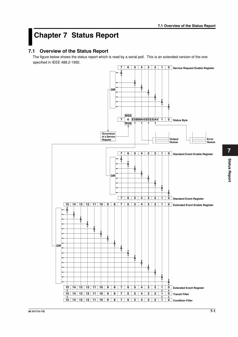
7-1IM 701710-17E
Statu
s Rep
ort
7
Chapter 7 Status Report
7.1 Overview of the Status ReportThe figure below shows the status report which is read by a serial poll. This is an extended version of the one
specified in IEEE 488.2-1992.
15 14 13 12 11 10 9 8 7 6 5 4 3 2 1 0
15 14 13 12 11 10 9 8 7 6 5 4 3 2 1 0
15 14 13 12 11 10 9 8 7 6 5 4 3 2 1 0
Condition Filter
Transit Filter
Extended Event Register
&
15 14 13 12 11 10 9 8 7 6 5 4 3 2 1 0 Extended Event Enable Register
&
&
&
&
&
&
&
&
&
&
&
&
&
&
&
7 6 5 4 3 2 1 0 Standard Event Register
&
&
&
&
&
&
&
&
7 6 5 4 3 2 1 0 Standard Event Enable Register
OR
OR
7 6 ESBMAVEES EAV 1 0 Status Byte
MSS
RQS
Output Queue
Error Queue
Occurrence of a Service Request
&
&
&
&
&
&
&
7 6 5 4 3 2 1 0 Service Request Enable Register
OR
7.1 Overview of the Status Report
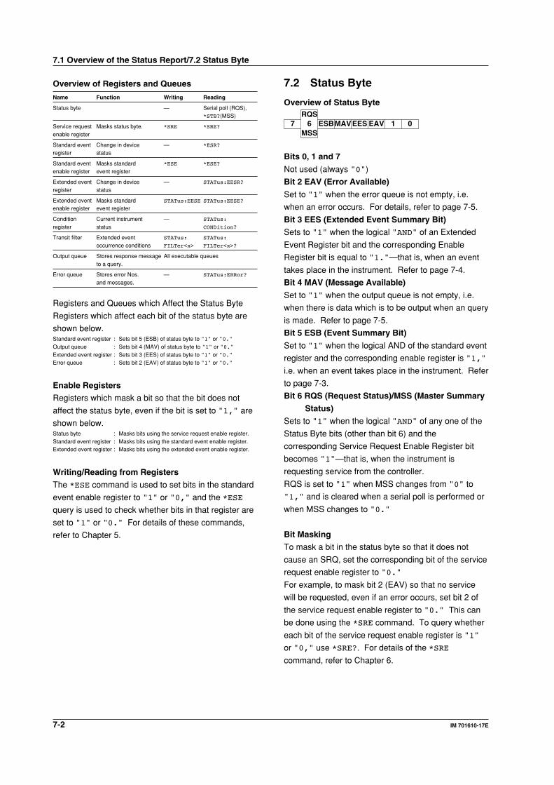
7-2 IM 701610-17E
Overview of Registers and Queues
Name Function Writing Reading
Status byte — Serial poll (RQS),*STB?(MSS)
Service request Masks status byte. *SRE *SRE?
enable register
Standard event Change in device — *ESR?
register status
Standard event Masks standard *ESE *ESE?
enable register event register
Extended event Change in device — STATus:EESR?
register status
Extended event Masks standard STATus:EESE STATus:EESE?
enable register event register
Condition Current instrument — STATus:
register status CONDition?
Transit filter Extended event STATus: STATus:
occurrence conditions FILTer<x> FILTer<x>?
Output queue Stores response message All executable queuesto a query.
Error queue Stores error Nos. — STATus:ERRor?
and messages.
Registers and Queues which Affect the Status Byte
Registers which affect each bit of the status byte are
shown below.Standard event register : Sets bit 5 (ESB) of status byte to "1" or "0."Output queue : Sets bit 4 (MAV) of status byte to "1" or "0."Extended event register : Sets bit 3 (EES) of status byte to "1" or "0."Error queue : Sets bit 2 (EAV) of status byte to "1" or "0."
Enable Registers
Registers which mask a bit so that the bit does not
affect the status byte, even if the bit is set to "1," are
shown below.Status byte : Masks bits using the service request enable register.Standard event register : Masks bits using the standard event enable register.Extended event register : Masks bits using the extended event enable register.
Writing/Reading from Registers
The *ESE command is used to set bits in the standard
event enable register to "1" or "0," and the *ESE
query is used to check whether bits in that register are
set to "1" or "0." For details of these commands,
refer to Chapter 5.
7.2 Status Byte
Overview of Status Byte
7 6 ESBMAVEES EAV 1 0RQS
MSS
Bits 0, 1 and 7
Not used (always "0")
Bit 2 EAV (Error Available)
Set to "1" when the error queue is not empty, i.e.
when an error occurs. For details, refer to page 7-5.
Bit 3 EES (Extended Event Summary Bit)
Sets to "1" when the logical "AND" of an Extended
Event Register bit and the corresponding Enable
Register bit is equal to "1."—that is, when an event
takes place in the instrument. Refer to page 7-4.
Bit 4 MAV (Message Available)
Set to "1" when the output queue is not empty, i.e.
when there is data which is to be output when an query
is made. Refer to page 7-5.
Bit 5 ESB (Event Summary Bit)
Set to "1" when the logical AND of the standard event
register and the corresponding enable register is "1,"
i.e. when an event takes place in the instrument. Refer
to page 7-3.
Bit 6 RQS (Request Status)/MSS (Master Summary
Status)
Sets to "1" when the logical "AND" of any one of the
Status Byte bits (other than bit 6) and the
corresponding Service Request Enable Register bit
becomes "1"—that is, when the instrument is
requesting service from the controller.
RQS is set to "1" when MSS changes from "0" to
"1," and is cleared when a serial poll is performed or
when MSS changes to "0."
Bit Masking
To mask a bit in the status byte so that it does not
cause an SRQ, set the corresponding bit of the service
request enable register to "0."
For example, to mask bit 2 (EAV) so that no service
will be requested, even if an error occurs, set bit 2 of
the service request enable register to "0." This can
be done using the *SRE command. To query whether
each bit of the service request enable register is "1"
or "0," use *SRE?. For details of the *SRE
command, refer to Chapter 6.
7.1 Overview of the Status Report/7.2 Status Byte
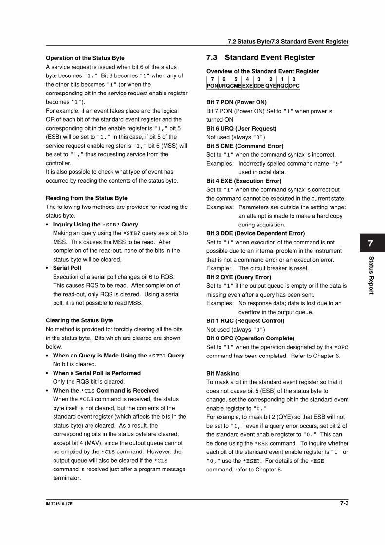
Statu
s Rep
ort
7-3IM 701610-17E
7
Operation of the Status Byte
A service request is issued when bit 6 of the status
byte becomes "1." Bit 6 becomes "1" when any of
the other bits becomes "1" (or when the
corresponding bit in the service request enable register
becomes "1").
For example, if an event takes place and the logical
OR of each bit of the standard event register and the
corresponding bit in the enable register is "1," bit 5
(ESB) will be set to "1." In this case, if bit 5 of the
service request enable register is "1," bit 6 (MSS) will
be set to "1," thus requesting service from the
controller.
It is also possible to check what type of event has
occurred by reading the contents of the status byte.
Reading from the Status Byte
The following two methods are provided for reading the
status byte.
• Inquiry Using the *STB? Query
Making an query using the *STB? query sets bit 6 to
MSS. This causes the MSS to be read. After
completion of the read-out, none of the bits in the
status byte will be cleared.
• Serial Poll
Execution of a serial poll changes bit 6 to RQS.
This causes RQS to be read. After completion of
the read-out, only RQS is cleared. Using a serial
poll, it is not possible to read MSS.
Clearing the Status Byte
No method is provided for forcibly clearing all the bits
in the status byte. Bits which are cleared are shown
below.
• When an Query is Made Using the *STB? Query
No bit is cleared.
• When a Serial Poll is Performed
Only the RQS bit is cleared.
• When the *CLS Command is Received
When the *CLS command is received, the status
byte itself is not cleared, but the contents of the
standard event register (which affects the bits in the
status byte) are cleared. As a result, the
corresponding bits in the status byte are cleared,
except bit 4 (MAV), since the output queue cannot
be emptied by the *CLS command. However, the
output queue will also be cleared if the *CLS
command is received just after a program message
terminator.
7.3 Standard Event Register
Overview of the Standard Event Register
URQ6
PON7 5 4 3 2 1 0
CMEEXE DDEQYERQCOPC
Bit 7 PON (Power ON)
Bit 7 PON (Power ON) Set to "1" when power is
turned ON
Bit 6 URQ (User Request)
Not used (always "0")
Bit 5 CME (Command Error)
Set to "1" when the command syntax is incorrect.
Examples: Incorrectly spelled command name; "9"
used in octal data.
Bit 4 EXE (Execution Error)
Set to "1" when the command syntax is correct but
the command cannot be executed in the current state.
Examples: Parameters are outside the setting range:
an attempt is made to make a hard copy
during acquisition.
Bit 3 DDE (Device Dependent Error)
Set to "1" when execution of the command is not
possible due to an internal problem in the instrument
that is not a command error or an execution error.
Example: The circuit breaker is reset.
Bit 2 QYE (Query Error)
Set to "1" if the output queue is empty or if the data is
missing even after a query has been sent.
Examples: No response data; data is lost due to an
overflow in the output queue.
Bit 1 RQC (Request Control)
Not used (always "0")
Bit 0 OPC (Operation Complete)
Set to "1" when the operation designated by the *OPC
command has been completed. Refer to Chapter 6.
Bit Masking
To mask a bit in the standard event register so that it
does not cause bit 5 (ESB) of the status byte to
change, set the corresponding bit in the standard event
enable register to "0."
For example, to mask bit 2 (QYE) so that ESB will not
be set to "1," even if a query error occurs, set bit 2 of
the standard event enable register to "0." This can
be done using the *ESE command. To inquire whether
each bit of the standard event enable register is "1" or
"0," use the *ESE?. For details of the *ESE
command, refer to Chapter 6.
7.2 Status Byte/7.3 Standard Event Register
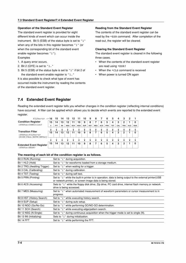
7-4 IM 701610-17E
Operation of the Standard Event Register
The standard event register is provided for eight
different kinds of event which can occur inside the
instrument. Bit 5 (ESB) of the status byte is set to "1"
when any of the bits in this register becomes "1" (or
when the corresponding bit of the standard event
enable register becomes "1").
Examples
1. A query error occurs.
2. Bit 2 (QYE) is set to "1."
3. Bit 5 (ESB) of the status byte is set to "1" if bit 2 of
the standard event enable register is "1."
It is also possible to check what type of event has
occurred inside the instrument by reading the contents
of the standard event register.
Reading from the Standard Event Register
The contents of the standard event register can be
read by the *ESR command. After completion of the
read-out, the register will be cleared.
Clearing the Standard Event Register
The standard event register is cleared in the following
three cases.
• When the contents of the standard event register
are read using *ESR?
• When the *CLS command is received
• When power is turned ON again
7.3 Standard Event Register/7.4 Extended Event Register
7.4 Extended Event Register
Reading the extended event register tells you whether changes in the condition register (reflecting internal conditions)
have occurred. A filter can be applied which allows you to decide which events are reported to the extended event
register.
ACS
6MES
7 5 4 3 2 1 0PRN TST CAL TRG HLD RUNHST
8SUP
9NGO
10SCH
11NSG
12INI
13FFT
140
15
67 5 4 3 2 1 089101112131415
Condition Register:STATus:CONDition?
Transition Filter
01415Extended Event Register
167 5 4 38910111213 2
67 5 4 3 2 18910111213141516
:STATus:FILTer<x>RISE|FALL|BOTH|NEVer
:STATus:EESR?
FILTer<x> ->
The meaning of each bit of the condition register is as follows.Bit 0 RUN (Running) Set to "1" during acquisition.
Bit 1 HLD (Hold) Set to "1" for waveforms loaded from a storage medium.
Bit 2 TRG (Awaiting Trigger) Set to "1" when waiting for a trigger.
Bit 3 CAL (Calibrating) Set to "1" during calibration.
Bit 4 TST (Testing) Set to "1" during self-test.
Bit 5 PRN (Printing) Set to "1" while the built-in printer is in operation, data is being output to the external printer(USBor network printer), or screen image data is being stored.
Bit 6 ACS (Accessing) Sets to "1" while the floppy disk drive, Zip drive, PC card drive, internel flash memory,or networkdrive is being accessed.
Bit 7 MES (Measuring) Set to "1" when automated measurement of waveform parameters or cursor measurement is inprogress.
Bit 8 HST (History Search) Set to "1" while executing history search.
Bit 9 SUP (Setup) Set to "1" during auto setup.
Bit 10 NGO (Go/No-Go) Set to "1" while performing GO/NO-GO determination.
Bit 11 SCH (Search) Set to "1" while executing edge/pattern search.
Bit 12 NSG (N-Single) Set to "1" during continuous acquisition when the trigger mode is set to single (N).
Bit 13 INI (Initializing) Sets to "1" during initialization.
Bit 14 FFT Set to "1" while performing the FFT.
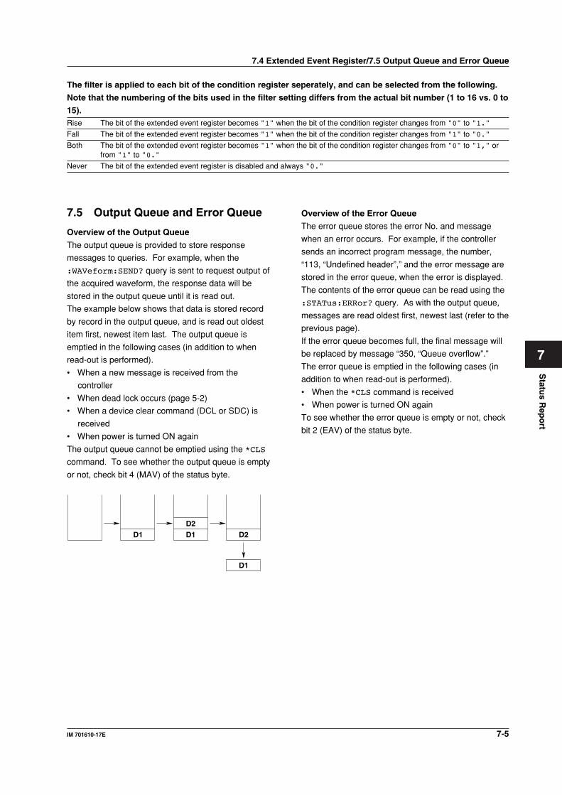
Statu
s Rep
ort
7-5IM 701610-17E
7
7.4 Extended Event Register/7.5 Output Queue and Error Queue
The filter is applied to each bit of the condition register seperately, and can be selected from the following.
Note that the numbering of the bits used in the filter setting differs from the actual bit number (1 to 16 vs. 0 to
15).Rise The bit of the extended event register becomes "1" when the bit of the condition register changes from "0" to "1."
Fall The bit of the extended event register becomes "1" when the bit of the condition register changes from "1" to "0."
Both The bit of the extended event register becomes "1" when the bit of the condition register changes from "0" to "1," orfrom "1" to "0."
Never The bit of the extended event register is disabled and always "0."
7.5 Output Queue and Error Queue
Overview of the Output Queue
The output queue is provided to store response
messages to queries. For example, when the
:WAVeform:SEND? query is sent to request output of
the acquired waveform, the response data will be
stored in the output queue until it is read out.
The example below shows that data is stored record
by record in the output queue, and is read out oldest
item first, newest item last. The output queue is
emptied in the following cases (in addition to when
read-out is performed).
• When a new message is received from the
controller
• When dead lock occurs (page 5-2)
• When a device clear command (DCL or SDC) is
received
• When power is turned ON again
The output queue cannot be emptied using the *CLS
command. To see whether the output queue is empty
or not, check bit 4 (MAV) of the status byte.
D1D2D1 D2
D1
Overview of the Error Queue
The error queue stores the error No. and message
when an error occurs. For example, if the controller
sends an incorrect program message, the number,
“113, “Undefined header”,” and the error message are
stored in the error queue, when the error is displayed.
The contents of the error queue can be read using the
:STATus:ERRor? query. As with the output queue,
messages are read oldest first, newest last (refer to the
previous page).
If the error queue becomes full, the final message will
be replaced by message “350, “Queue overflow”.”
The error queue is emptied in the following cases (in
addition to when read-out is performed).
• When the *CLS command is received
• When power is turned ON again
To see whether the error queue is empty or not, check
bit 2 (EAV) of the status byte.
Sam
ple P
rog
ram
8-1IM 701610-17E
8
Chapter 8 Sample Program
8.1 Before Programming
EnvironmentModel: MS-DOS/V Computer
Language: Visual BASIC Ver. 6.0 Professional Edition or more
GP-IB board: AT-GPIB/TNT IEEE-488.2 board from National Instruments.
Setting up the Visual BasicCompornent: MSComm
Standardmodule: Niglobal.bas
Vbib-32.bas
Setting up the DL1620/DL1640/DL1640LGP-IB
All the sample programs given in this chapter use address 1 for the DL1620/DL1640/
DL1640L, so be sure to assign the instrument to address 1 as described on page 2-6.
Serial (RS-232)
All the sample programs in this chapter assume the below settings, so be sure to set
parameters as described on page 1-8.
Baud Rate: 19200
Handshake: CTS-RTS
Parity Check: NO
Stop Bit: 1
Character Length: 8
Terminator: LF
8.1 Before Programming
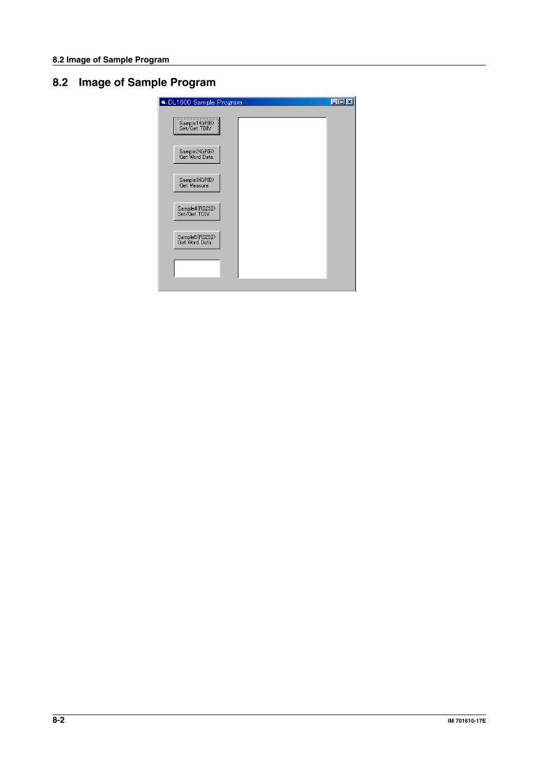
8-2 IM 701610-17E
8.2 Image of Sample Program
8.2 Image of Sample Program
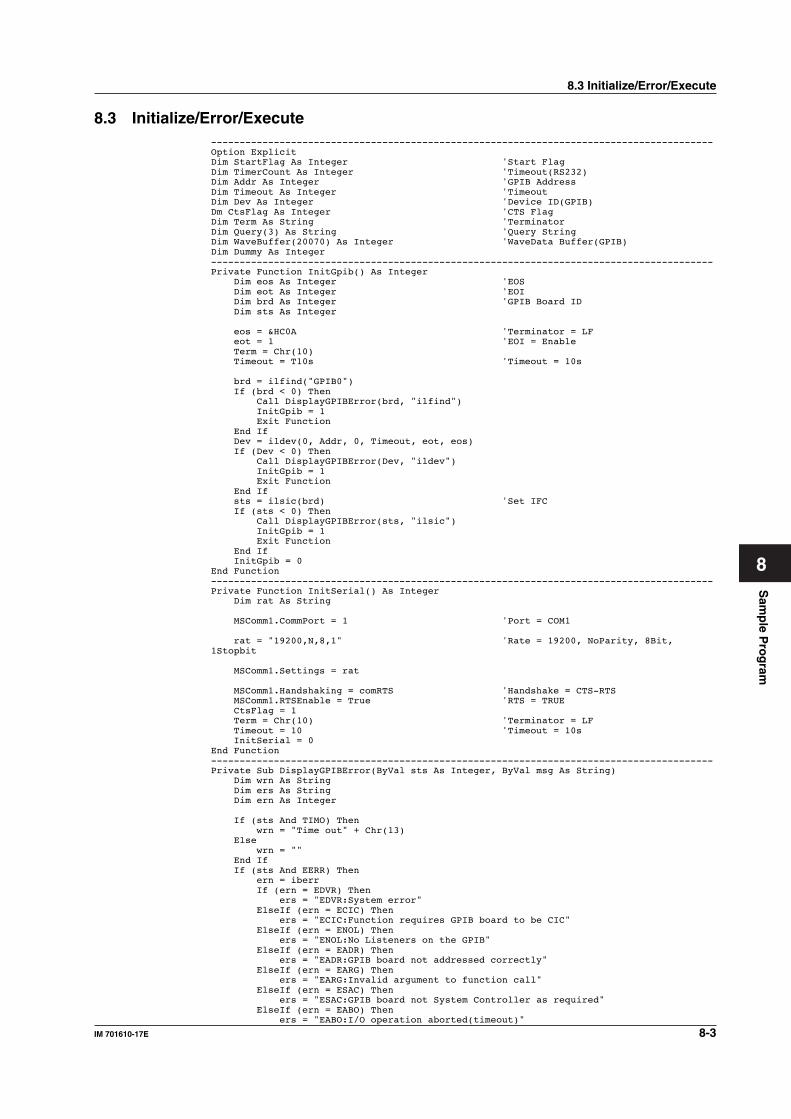
Sam
ple P
rog
ram
8-3IM 701610-17E
8
8.3 Initialize/Error/Execute----------------------------------------------------------------------------------------Option ExplicitDim StartFlag As Integer 'Start FlagDim TimerCount As Integer 'Timeout(RS232)Dim Addr As Integer 'GPIB AddressDim Timeout As Integer 'TimeoutDim Dev As Integer 'Device ID(GPIB)Dm CtsFlag As Integer 'CTS FlagDim Term As String 'TerminatorDim Query(3) As String 'Query StringDim WaveBuffer(20070) As Integer 'WaveData Buffer(GPIB)Dim Dummy As Integer----------------------------------------------------------------------------------------Private Function InitGpib() As Integer Dim eos As Integer 'EOS Dim eot As Integer 'EOI Dim brd As Integer 'GPIB Board ID Dim sts As Integer
eos = &HC0A 'Terminator = LF eot = 1 'EOI = Enable Term = Chr(10) Timeout = T10s 'Timeout = 10s
brd = ilfind("GPIB0") If (brd < 0) Then Call DisplayGPIBError(brd, "ilfind") InitGpib = 1 Exit Function End If Dev = ildev(0, Addr, 0, Timeout, eot, eos) If (Dev < 0) Then Call DisplayGPIBError(Dev, "ildev") InitGpib = 1 Exit Function End If sts = ilsic(brd) 'Set IFC If (sts < 0) Then Call DisplayGPIBError(sts, "ilsic") InitGpib = 1 Exit Function End If InitGpib = 0End Function----------------------------------------------------------------------------------------Private Function InitSerial() As Integer Dim rat As String
MSComm1.CommPort = 1 'Port = COM1
rat = "19200,N,8,1" 'Rate = 19200, NoParity, 8Bit,1Stopbit
MSComm1.Settings = rat
MSComm1.Handshaking = comRTS 'Handshake = CTS-RTS MSComm1.RTSEnable = True 'RTS = TRUE CtsFlag = 1 Term = Chr(10) 'Terminator = LF Timeout = 10 'Timeout = 10s InitSerial = 0End Function----------------------------------------------------------------------------------------Private Sub DisplayGPIBError(ByVal sts As Integer, ByVal msg As String) Dim wrn As String Dim ers As String Dim ern As Integer
If (sts And TIMO) Then wrn = "Time out" + Chr(13) Else wrn = "" End If If (sts And EERR) Then ern = iberr If (ern = EDVR) Then ers = "EDVR:System error" ElseIf (ern = ECIC) Then ers = "ECIC:Function requires GPIB board to be CIC" ElseIf (ern = ENOL) Then ers = "ENOL:No Listeners on the GPIB" ElseIf (ern = EADR) Then ers = "EADR:GPIB board not addressed correctly" ElseIf (ern = EARG) Then ers = "EARG:Invalid argument to function call" ElseIf (ern = ESAC) Then ers = "ESAC:GPIB board not System Controller as required" ElseIf (ern = EABO) Then ers = "EABO:I/O operation aborted(timeout)"
8.3 Initialize/Error/Execute
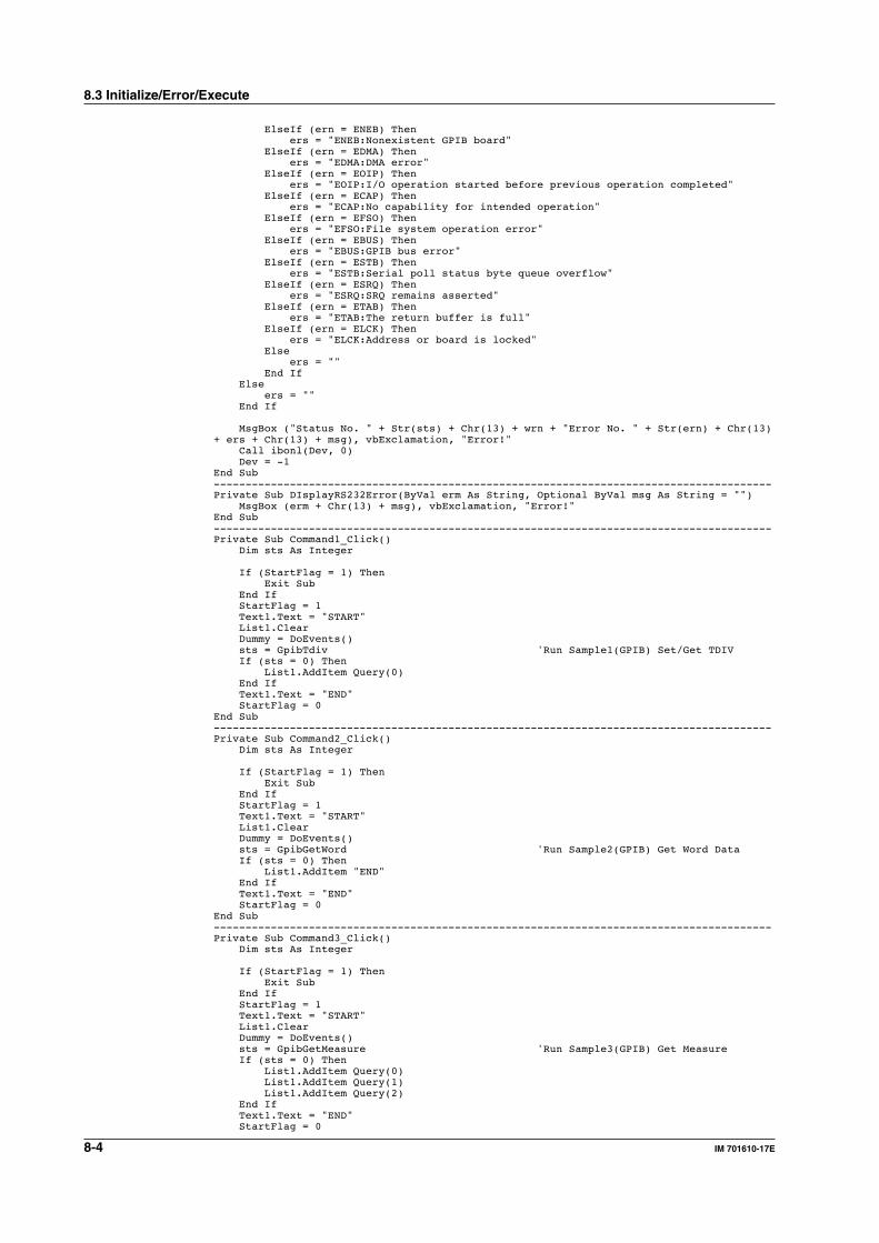
8-4 IM 701610-17E
ElseIf (ern = ENEB) Then ers = "ENEB:Nonexistent GPIB board" ElseIf (ern = EDMA) Then ers = "EDMA:DMA error" ElseIf (ern = EOIP) Then ers = "EOIP:I/O operation started before previous operation completed" ElseIf (ern = ECAP) Then ers = "ECAP:No capability for intended operation" ElseIf (ern = EFSO) Then ers = "EFSO:File system operation error" ElseIf (ern = EBUS) Then ers = "EBUS:GPIB bus error" ElseIf (ern = ESTB) Then ers = "ESTB:Serial poll status byte queue overflow" ElseIf (ern = ESRQ) Then ers = "ESRQ:SRQ remains asserted" ElseIf (ern = ETAB) Then ers = "ETAB:The return buffer is full" ElseIf (ern = ELCK) Then ers = "ELCK:Address or board is locked" Else ers = "" End If Else ers = "" End If
MsgBox ("Status No. " + Str(sts) + Chr(13) + wrn + "Error No. " + Str(ern) + Chr(13)+ ers + Chr(13) + msg), vbExclamation, "Error!" Call ibonl(Dev, 0) Dev = -1End Sub----------------------------------------------------------------------------------------Private Sub DIsplayRS232Error(ByVal erm As String, Optional ByVal msg As String = "") MsgBox (erm + Chr(13) + msg), vbExclamation, "Error!"End Sub----------------------------------------------------------------------------------------Private Sub Command1_Click() Dim sts As Integer
If (StartFlag = 1) Then Exit Sub End If StartFlag = 1 Text1.Text = "START" List1.Clear Dummy = DoEvents() sts = GpibTdiv 'Run Sample1(GPIB) Set/Get TDIV If (sts = 0) Then List1.AddItem Query(0) End If Text1.Text = "END" StartFlag = 0End Sub----------------------------------------------------------------------------------------Private Sub Command2_Click() Dim sts As Integer
If (StartFlag = 1) Then Exit Sub End If StartFlag = 1 Text1.Text = "START" List1.Clear Dummy = DoEvents() sts = GpibGetWord 'Run Sample2(GPIB) Get Word Data If (sts = 0) Then List1.AddItem "END" End If Text1.Text = "END" StartFlag = 0End Sub----------------------------------------------------------------------------------------Private Sub Command3_Click() Dim sts As Integer
If (StartFlag = 1) Then Exit Sub End If StartFlag = 1 Text1.Text = "START" List1.Clear Dummy = DoEvents() sts = GpibGetMeasure 'Run Sample3(GPIB) Get Measure If (sts = 0) Then List1.AddItem Query(0) List1.AddItem Query(1) List1.AddItem Query(2) End If Text1.Text = "END" StartFlag = 0
8.3 Initialize/Error/Execute
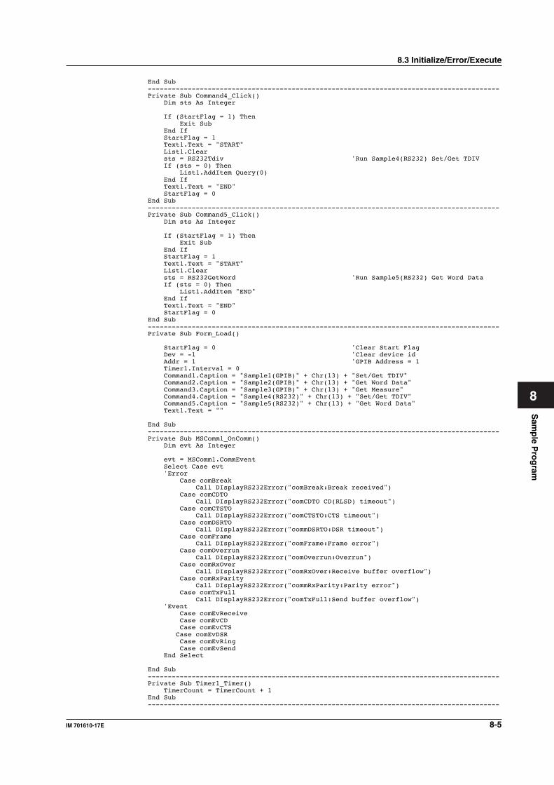
Sam
ple P
rog
ram
8-5IM 701610-17E
8
End Sub----------------------------------------------------------------------------------------Private Sub Command4_Click() Dim sts As Integer
If (StartFlag = 1) Then Exit Sub End If StartFlag = 1 Text1.Text = "START" List1.Clear sts = RS232Tdiv 'Run Sample4(RS232) Set/Get TDIV If (sts = 0) Then List1.AddItem Query(0) End If Text1.Text = "END" StartFlag = 0End Sub----------------------------------------------------------------------------------------Private Sub Command5_Click() Dim sts As Integer
If (StartFlag = 1) Then Exit Sub End If StartFlag = 1 Text1.Text = "START" List1.Clear sts = RS232GetWord 'Run Sample5(RS232) Get Word Data If (sts = 0) Then List1.AddItem "END" End If Text1.Text = "END" StartFlag = 0End Sub----------------------------------------------------------------------------------------Private Sub Form_Load()
StartFlag = 0 'Clear Start Flag Dev = -1 'Clear device id Addr = 1 'GPIB Address = 1 Timer1.Interval = 0 Command1.Caption = "Sample1(GPIB)" + Chr(13) + "Set/Get TDIV" Command2.Caption = "Sample2(GPIB)" + Chr(13) + "Get Word Data" Command3.Caption = "Sample3(GPIB)" + Chr(13) + "Get Measure" Command4.Caption = "Sample4(RS232)" + Chr(13) + "Set/Get TDIV" Command5.Caption = "Sample5(RS232)" + Chr(13) + "Get Word Data" Text1.Text = ""
End Sub----------------------------------------------------------------------------------------Private Sub MSComm1_OnComm() Dim evt As Integer
evt = MSComm1.CommEvent Select Case evt 'Error Case comBreak Call DIsplayRS232Error("comBreak:Break received") Case comCDTO Call DIsplayRS232Error("comCDTO CD(RLSD) timeout") Case comCTSTO Call DIsplayRS232Error("comCTSTO:CTS timeout") Case comDSRTO Call DIsplayRS232Error("commDSRTO:DSR timeout") Case comFrame Call DIsplayRS232Error("comFrame:Frame error") Case comOverrun Call DIsplayRS232Error("comOverrun:Overrun") Case comRxOver Call DIsplayRS232Error("comRxOver:Receive buffer overflow") Case comRxParity Call DIsplayRS232Error("commRxParity:Parity error") Case comTxFull Call DIsplayRS232Error("comTxFull:Send buffer overflow") 'Event Case comEvReceive Case comEvCD Case comEvCTS Case comEvDSR Case comEvRing Case comEvSend End Select
End Sub----------------------------------------------------------------------------------------Private Sub Timer1_Timer() TimerCount = TimerCount + 1End Sub----------------------------------------------------------------------------------------
8.3 Initialize/Error/Execute
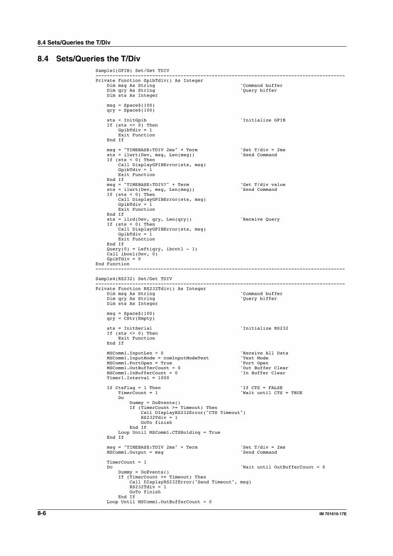
8-6 IM 701610-17E
8.4 Sets/Queries the T/DivSample1(GPIB) Set/Get TDIV----------------------------------------------------------------------------------------Private Function GpibTdiv() As Integer Dim msg As String 'Command buffer Dim qry As String 'Query biffer Dim sts As Integer
msg = Space$(100) qry = Space$(100)
sts = InitGpib 'Initialize GPIB If (sts <> 0) Then GpibTdiv = 1 Exit Function End If
msg = "TIMEBASE:TDIV 2ms" + Term 'Set T/div = 2ms sts = ilwrt(Dev, msg, Len(msg)) 'Send Command If (sts < 0) Then Call DisplayGPIBError(sts, msg) GpibTdiv = 1 Exit Function End If msg = "TIMEBASE:TDIV?" + Term 'Get T/div value sts = ilwrt(Dev, msg, Len(msg)) 'Send Command If (sts < 0) Then Call DisplayGPIBError(sts, msg) GpibTdiv = 1 Exit Function End If sts = ilrd(Dev, qry, Len(qry)) 'Receive Query If (sts < 0) Then Call DisplayGPIBError(sts, msg) GpibTdiv = 1 Exit Function End If Query(0) = Left(qry, ibcntl - 1) Call ibonl(Dev, 0) GpibTdiv = 0End Function----------------------------------------------------------------------------------------
Sample4(RS232) Set/Get TDIV----------------------------------------------------------------------------------------Private Function RS232Tdiv() As Integer Dim msg As String 'Command buffer Dim qry As String 'Query biffer Dim sts As Integer
msg = Space$(100) qry = CStr(Empty)
sts = InitSerial 'Initialize RS232 If (sts <> 0) Then Exit Function End If
MSComm1.InputLen = 0 'Receive All Data MSComm1.InputMode = comInputModeText 'Text Mode MSComm1.PortOpen = True 'Port Open MSComm1.OutBufferCount = 0 'Out Buffer Clear MSComm1.InBufferCount = 0 'In Buffer Clear Timer1.Interval = 1000
If CtsFlag = 1 Then 'If CTS = FALSE TimerCount = 1 'Wait until CTS = TRUE Do Dummy = DoEvents() If (TimerCount >= Timeout) Then Call DIsplayRS232Error("CTS Timeout") RS232Tdiv = 1 GoTo finish End If Loop Until MSComm1.CTSHolding = True End If
msg = "TIMEBASE:TDIV 2ms" + Term 'Set T/div = 2ms MSComm1.Output = msg 'Send Command
TimerCount = 1 Do 'Wait until OutBufferCount = 0 Dummy = DoEvents() If (TimerCount >= Timeout) Then Call DIsplayRS232Error("Send Timeout", msg) RS232Tdiv = 1 GoTo finish End If Loop Until MSComm1.OutBufferCount = 0
8.4 Sets/Queries the T/Div
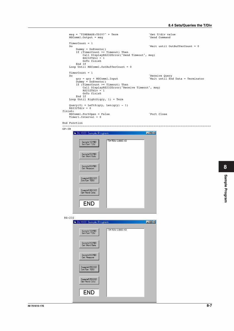
Sam
ple P
rog
ram
8-7IM 701610-17E
8
msg = "TIMEBASE:TDIV?" + Term 'Get T/div value MSComm1.Output = msg 'Send Command
TimerCount = 1 Do 'Wait until OutBufferCount = 0 Dummy = DoEvents() If (TimerCount >= Timeout) Then Call DIsplayRS232Error("Send Timeout", msg) RS232Tdiv = 1 GoTo finish End If Loop Until MSComm1.OutBufferCount = 0
TimerCount = 1 Do 'Receive Query qry = qry + MSComm1.Input 'Wait until End Data = Terminator Dummy = DoEvents() If (TimerCount >= Timeout) Then Call DIsplayRS232Error("Receive Timeout", msg) RS232Tdiv = 1 GoTo finish End If Loop Until Right$(qry, 1) = Term
Query(0) = Left$(qry, Len(qry) - 1) RS232Tdiv = 0finish: MSComm1.PortOpen = False 'Port Close Timer1.Interval = 0
End Function----------------------------------------------------------------------------------------GP-IB
RS-232
8.4 Sets/Queries the T/Div
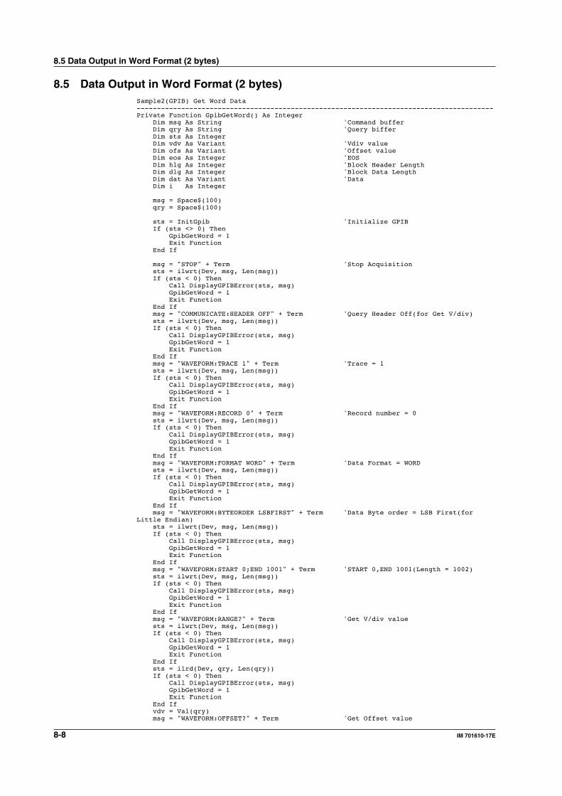
8-8 IM 701610-17E
8.5 Data Output in Word Format (2 bytes)Sample2(GPIB) Get Word Data----------------------------------------------------------------------------------------Private Function GpibGetWord() As Integer Dim msg As String 'Command buffer Dim qry As String 'Query biffer Dim sts As Integer Dim vdv As Variant 'Vdiv value Dim ofs As Variant 'Offset value Dim eos As Integer 'EOS Dim hlg As Integer 'Block Header Length Dim dlg As Integer 'Block Data Length Dim dat As Variant 'Data Dim i As Integer
msg = Space$(100) qry = Space$(100)
sts = InitGpib 'Initialize GPIB If (sts <> 0) Then GpibGetWord = 1 Exit Function End If
msg = "STOP" + Term 'Stop Acquisition sts = ilwrt(Dev, msg, Len(msg)) If (sts < 0) Then Call DisplayGPIBError(sts, msg) GpibGetWord = 1 Exit Function End If msg = "COMMUNICATE:HEADER OFF" + Term 'Query Header Off(for Get V/div) sts = ilwrt(Dev, msg, Len(msg)) If (sts < 0) Then Call DisplayGPIBError(sts, msg) GpibGetWord = 1 Exit Function End If msg = "WAVEFORM:TRACE 1" + Term 'Trace = 1 sts = ilwrt(Dev, msg, Len(msg)) If (sts < 0) Then Call DisplayGPIBError(sts, msg) GpibGetWord = 1 Exit Function End If msg = "WAVEFORM:RECORD 0" + Term 'Record number = 0 sts = ilwrt(Dev, msg, Len(msg)) If (sts < 0) Then Call DisplayGPIBError(sts, msg) GpibGetWord = 1 Exit Function End If msg = "WAVEFORM:FORMAT WORD" + Term 'Data Format = WORD sts = ilwrt(Dev, msg, Len(msg)) If (sts < 0) Then Call DisplayGPIBError(sts, msg) GpibGetWord = 1 Exit Function End If msg = "WAVEFORM:BYTEORDER LSBFIRST" + Term 'Data Byte order = LSB First(forLittle Endian) sts = ilwrt(Dev, msg, Len(msg)) If (sts < 0) Then Call DisplayGPIBError(sts, msg) GpibGetWord = 1 Exit Function End If msg = "WAVEFORM:START 0;END 1001" + Term 'START 0,END 1001(Length = 1002) sts = ilwrt(Dev, msg, Len(msg)) If (sts < 0) Then Call DisplayGPIBError(sts, msg) GpibGetWord = 1 Exit Function End If msg = "WAVEFORM:RANGE?" + Term 'Get V/div value sts = ilwrt(Dev, msg, Len(msg)) If (sts < 0) Then Call DisplayGPIBError(sts, msg) GpibGetWord = 1 Exit Function End If sts = ilrd(Dev, qry, Len(qry)) If (sts < 0) Then Call DisplayGPIBError(sts, msg) GpibGetWord = 1 Exit Function End If vdv = Val(qry) msg = "WAVEFORM:OFFSET?" + Term 'Get Offset value
8.5 Data Output in Word Format (2 bytes)
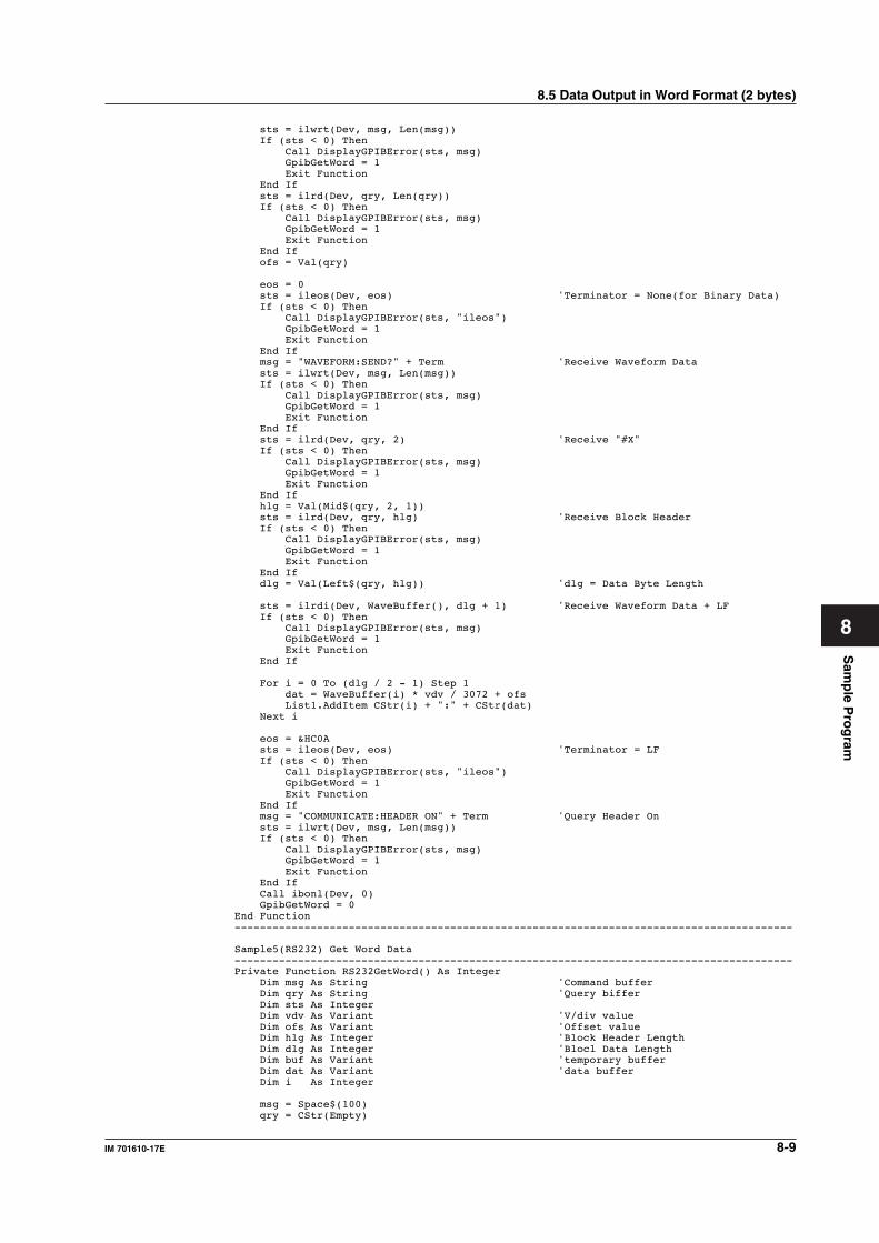
Sam
ple P
rog
ram
8-9IM 701610-17E
8
sts = ilwrt(Dev, msg, Len(msg)) If (sts < 0) Then Call DisplayGPIBError(sts, msg) GpibGetWord = 1 Exit Function End If sts = ilrd(Dev, qry, Len(qry)) If (sts < 0) Then Call DisplayGPIBError(sts, msg) GpibGetWord = 1 Exit Function End If ofs = Val(qry)
eos = 0 sts = ileos(Dev, eos) 'Terminator = None(for Binary Data) If (sts < 0) Then Call DisplayGPIBError(sts, "ileos") GpibGetWord = 1 Exit Function End If msg = "WAVEFORM:SEND?" + Term 'Receive Waveform Data sts = ilwrt(Dev, msg, Len(msg)) If (sts < 0) Then Call DisplayGPIBError(sts, msg) GpibGetWord = 1 Exit Function End If sts = ilrd(Dev, qry, 2) 'Receive "#X" If (sts < 0) Then Call DisplayGPIBError(sts, msg) GpibGetWord = 1 Exit Function End If hlg = Val(Mid$(qry, 2, 1)) sts = ilrd(Dev, qry, hlg) 'Receive Block Header If (sts < 0) Then Call DisplayGPIBError(sts, msg) GpibGetWord = 1 Exit Function End If dlg = Val(Left$(qry, hlg)) 'dlg = Data Byte Length
sts = ilrdi(Dev, WaveBuffer(), dlg + 1) 'Receive Waveform Data + LF If (sts < 0) Then Call DisplayGPIBError(sts, msg) GpibGetWord = 1 Exit Function End If
For i = 0 To (dlg / 2 - 1) Step 1 dat = WaveBuffer(i) * vdv / 3072 + ofs List1.AddItem CStr(i) + ":" + CStr(dat) Next i
eos = &HC0A sts = ileos(Dev, eos) 'Terminator = LF If (sts < 0) Then Call DisplayGPIBError(sts, "ileos") GpibGetWord = 1 Exit Function End If msg = "COMMUNICATE:HEADER ON" + Term 'Query Header On sts = ilwrt(Dev, msg, Len(msg)) If (sts < 0) Then Call DisplayGPIBError(sts, msg) GpibGetWord = 1 Exit Function End If Call ibonl(Dev, 0) GpibGetWord = 0End Function----------------------------------------------------------------------------------------
Sample5(RS232) Get Word Data----------------------------------------------------------------------------------------Private Function RS232GetWord() As Integer Dim msg As String 'Command buffer Dim qry As String 'Query biffer Dim sts As Integer Dim vdv As Variant 'V/div value Dim ofs As Variant 'Offset value Dim hlg As Integer 'Block Header Length Dim dlg As Integer 'Blocl Data Length Dim buf As Variant 'temporary buffer Dim dat As Variant 'data buffer Dim i As Integer
msg = Space$(100) qry = CStr(Empty)
8.5 Data Output in Word Format (2 bytes)
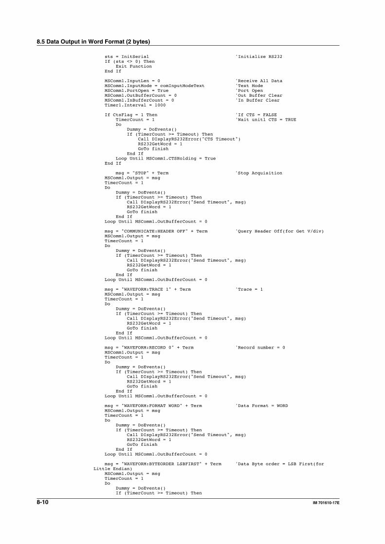
8-10 IM 701610-17E
sts = InitSerial 'Initialize RS232 If (sts <> 0) Then Exit Function End If
MSComm1.InputLen = 0 'Receive All Data MSComm1.InputMode = comInputModeText 'Text Mode MSComm1.PortOpen = True 'Port Open MSComm1.OutBufferCount = 0 'Out Buffer Clear MSComm1.InBufferCount = 0 'In Buffer Clear Timer1.Interval = 1000
If CtsFlag = 1 Then 'If CTS = FALSE TimerCount = 1 'Wait unitl CTS = TRUE Do Dummy = DoEvents() If (TimerCount >= Timeout) Then Call DIsplayRS232Error("CTS Timeout") RS232GetWord = 1 GoTo finish End If Loop Until MSComm1.CTSHolding = True End If
msg = "STOP" + Term 'Stop Acquisition MSComm1.Output = msg TimerCount = 1 Do Dummy = DoEvents() If (TimerCount >= Timeout) Then Call DIsplayRS232Error("Send Timeout", msg) RS232GetWord = 1 GoTo finish End If Loop Until MSComm1.OutBufferCount = 0
msg = "COMMUNICATE:HEADER OFF" + Term 'Query Header Off(for Get V/div) MSComm1.Output = msg TimerCount = 1 Do Dummy = DoEvents() If (TimerCount >= Timeout) Then Call DIsplayRS232Error("Send Timeout", msg) RS232GetWord = 1 GoTo finish End If Loop Until MSComm1.OutBufferCount = 0
msg = "WAVEFORM:TRACE 1" + Term 'Trace = 1 MSComm1.Output = msg TimerCount = 1 Do Dummy = DoEvents() If (TimerCount >= Timeout) Then Call DIsplayRS232Error("Send Timeout", msg) RS232GetWord = 1 GoTo finish End If Loop Until MSComm1.OutBufferCount = 0
msg = "WAVEFORM:RECORD 0" + Term 'Record number = 0 MSComm1.Output = msg TimerCount = 1 Do Dummy = DoEvents() If (TimerCount >= Timeout) Then Call DIsplayRS232Error("Send Timeout", msg) RS232GetWord = 1 GoTo finish End If Loop Until MSComm1.OutBufferCount = 0
msg = "WAVEFORM:FORMAT WORD" + Term 'Data Format = WORD MSComm1.Output = msg TimerCount = 1 Do Dummy = DoEvents() If (TimerCount >= Timeout) Then Call DIsplayRS232Error("Send Timeout", msg) RS232GetWord = 1 GoTo finish End If Loop Until MSComm1.OutBufferCount = 0
msg = "WAVEFORM:BYTEORDER LSBFIRST" + Term 'Data Byte order = LSB First(forLittle Endian) MSComm1.Output = msg TimerCount = 1 Do Dummy = DoEvents() If (TimerCount >= Timeout) Then
8.5 Data Output in Word Format (2 bytes)
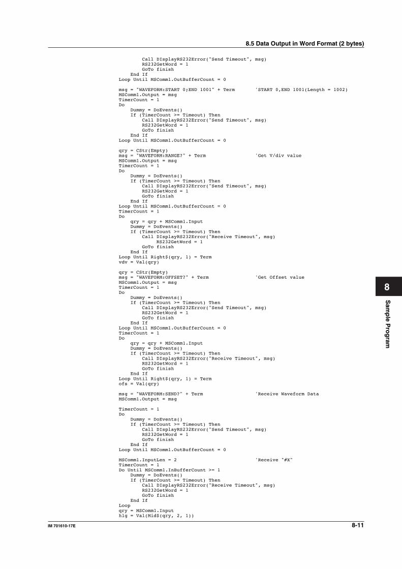
Sam
ple P
rog
ram
8-11IM 701610-17E
8
Call DIsplayRS232Error("Send Timeout", msg) RS232GetWord = 1 GoTo finish End If Loop Until MSComm1.OutBufferCount = 0
msg = "WAVEFORM:START 0;END 1001" + Term 'START 0,END 1001(Length = 1002) MSComm1.Output = msg TimerCount = 1 Do Dummy = DoEvents() If (TimerCount >= Timeout) Then Call DIsplayRS232Error("Send Timeout", msg) RS232GetWord = 1 GoTo finish End If Loop Until MSComm1.OutBufferCount = 0
qry = CStr(Empty) msg = "WAVEFORM:RANGE?" + Term 'Get V/div value MSComm1.Output = msg TimerCount = 1 Do Dummy = DoEvents() If (TimerCount >= Timeout) Then Call DIsplayRS232Error("Send Timeout", msg) RS232GetWord = 1 GoTo finish End If Loop Until MSComm1.OutBufferCount = 0 TimerCount = 1 Do qry = qry + MSComm1.Input Dummy = DoEvents() If (TimerCount >= Timeout) Then Call DIsplayRS232Error("Receive Timeout", msg)
RS232GetWord = 1 GoTo finish End If Loop Until Right$(qry, 1) = Term vdv = Val(qry)
qry = CStr(Empty) msg = "WAVEFORM:OFFSET?" + Term 'Get Offset value MSComm1.Output = msg TimerCount = 1 Do Dummy = DoEvents() If (TimerCount >= Timeout) Then Call DIsplayRS232Error("Send Timeout", msg) RS232GetWord = 1 GoTo finish End If Loop Until MSComm1.OutBufferCount = 0 TimerCount = 1 Do qry = qry + MSComm1.Input Dummy = DoEvents() If (TimerCount >= Timeout) Then Call DIsplayRS232Error("Receive Timeout", msg) RS232GetWord = 1 GoTo finish End If Loop Until Right$(qry, 1) = Term ofs = Val(qry)
msg = "WAVEFORM:SEND?" + Term 'Receive Waveform Data MSComm1.Output = msg
TimerCount = 1 Do Dummy = DoEvents() If (TimerCount >= Timeout) Then Call DIsplayRS232Error("Send Timeout", msg) RS232GetWord = 1 GoTo finish End If Loop Until MSComm1.OutBufferCount = 0
MSComm1.InputLen = 2 'Receive "#X" TimerCount = 1 Do Until MSComm1.InBufferCount >= 1 Dummy = DoEvents() If (TimerCount >= Timeout) Then Call DIsplayRS232Error("Receive Timeout", msg) RS232GetWord = 1 GoTo finish End If Loop qry = MSComm1.Input hlg = Val(Mid$(qry, 2, 1))
8.5 Data Output in Word Format (2 bytes)
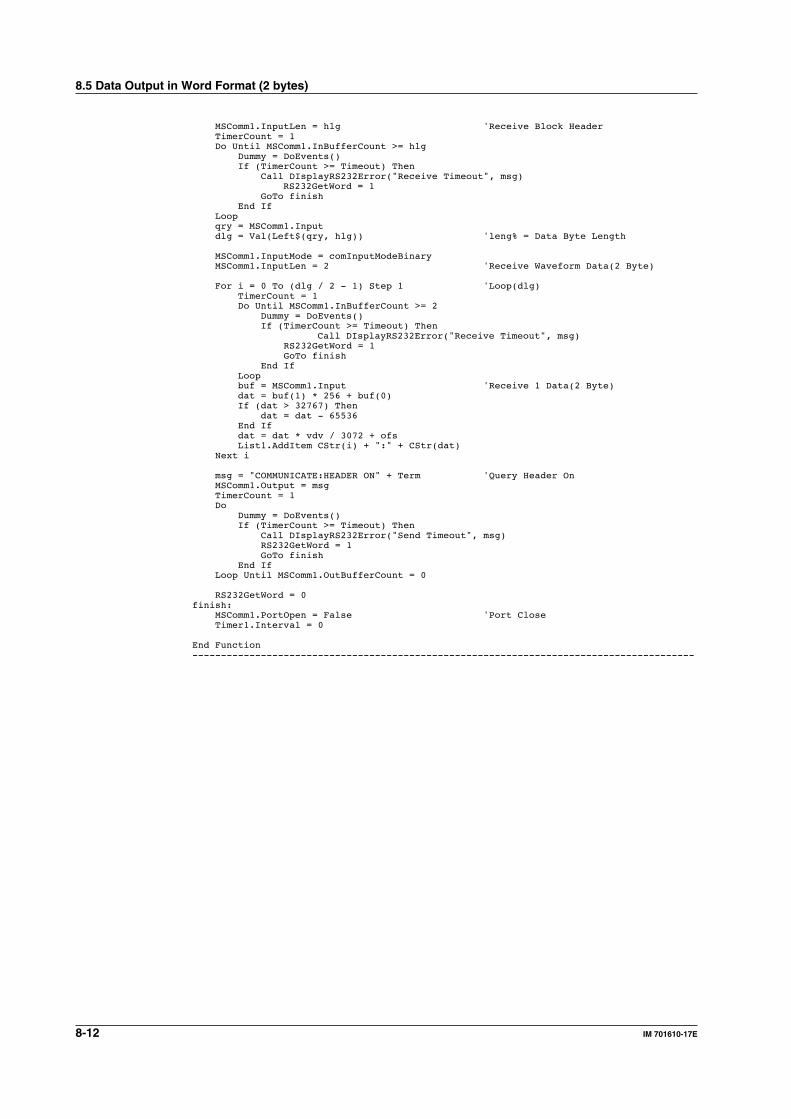
8-12 IM 701610-17E
MSComm1.InputLen = hlg 'Receive Block Header TimerCount = 1 Do Until MSComm1.InBufferCount >= hlg Dummy = DoEvents() If (TimerCount >= Timeout) Then Call DIsplayRS232Error("Receive Timeout", msg)
RS232GetWord = 1 GoTo finish End If Loop qry = MSComm1.Input dlg = Val(Left$(qry, hlg)) 'leng% = Data Byte Length
MSComm1.InputMode = comInputModeBinary MSComm1.InputLen = 2 'Receive Waveform Data(2 Byte)
For i = 0 To (dlg / 2 - 1) Step 1 'Loop(dlg) TimerCount = 1 Do Until MSComm1.InBufferCount >= 2 Dummy = DoEvents() If (TimerCount >= Timeout) Then
Call DIsplayRS232Error("Receive Timeout", msg) RS232GetWord = 1 GoTo finish End If Loop buf = MSComm1.Input 'Receive 1 Data(2 Byte) dat = buf(1) * 256 + buf(0) If (dat > 32767) Then dat = dat - 65536 End If dat = dat * vdv / 3072 + ofs List1.AddItem CStr(i) + ":" + CStr(dat) Next i
msg = "COMMUNICATE:HEADER ON" + Term 'Query Header On MSComm1.Output = msg TimerCount = 1 Do Dummy = DoEvents() If (TimerCount >= Timeout) Then Call DIsplayRS232Error("Send Timeout", msg) RS232GetWord = 1 GoTo finish End If Loop Until MSComm1.OutBufferCount = 0
RS232GetWord = 0finish: MSComm1.PortOpen = False 'Port Close Timer1.Interval = 0
End Function----------------------------------------------------------------------------------------
8.5 Data Output in Word Format (2 bytes)
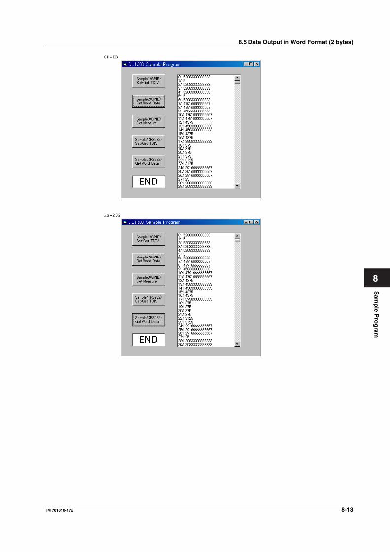
Sam
ple P
rog
ram
8-13IM 701610-17E
8
8.5 Data Output in Word Format (2 bytes)
GP-IB
RS-232
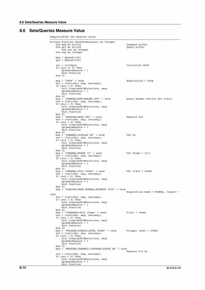
8-14 IM 701610-17E
8.6 Sets/Queries Measure Value
8.6 Sets/Queries Measure ValueSample3(GPIB) Get Measure value----------------------------------------------------------------------------------------Private Function GpibGetMeasure() As Integer Dim msg As String 'Command buffer Dim qry As String 'Query biffer
Dim sts As Integer Dim stp As Integer
msg = Space$(100) qry = Space$(100)
sts = InitGpib 'Initialize GPIB If (sts <> 0) Then GpibGetMeasure = 1 Exit Function End If
msg = "STOP" + term 'Acquisition = Stop sts = ilwrt(Dev, msg, Len(msg)) If (sts < 0) Then Call DisplayGPIBError(sts, msg) GpibGetMeasure = 1 Exit Function End If msg = "COMMUNICATE:HEADER OFF" + term 'Query Header Off(for Get V/div) sts = ilwrt(Dev, msg, Len(msg)) If (sts < 0) Then Call DisplayGPIBError(sts, msg) GpibGetMeasure = 1 Exit Function End If msg = "MEASURE:MODE OFF" + term 'Measure Off sts = ilwrt(Dev, msg, Len(msg)) If (sts < 0) Then Call DisplayGPIBError(sts, msg) GpibGetMeasure = 1 Exit Function End If msg = "CHANNEL:DISPLAY ON" + term 'CH1 On sts = ilwrt(Dev, msg, Len(msg)) If (sts < 0) Then Call DisplayGPIBError(sts, msg) GpibGetMeasure = 1 Exit Function End If msg = "CHANNEL:PROBE 10" + term 'CH1 Probe = 10:1 sts = ilwrt(Dev, msg, Len(msg)) If (sts < 0) Then Call DisplayGPIBError(sts, msg) GpibGetMeasure = 1 Exit Function End If msg = "CHANNEL:VDIV 500mV" + term 'CH1 V/div = 500mV sts = ilwrt(Dev, msg, Len(msg)) If (sts < 0) Then Call DisplayGPIBError(sts, msg) GpibGetMeasure = 1 Exit Function End If msg = "ACQUIRE:MODE NORMAL;RLENGTH 1000" + term 'Acquisition mode = NORMAL, length =1000 sts = ilwrt(Dev, msg, Len(msg)) If (sts < 0) Then Call DisplayGPIBError(sts, msg) GpibGetMeasure = 1 Exit Function End If msg = "TIMEBASE:TDIV 100ms" + term 'T/div = 100ms sts = ilwrt(Dev, msg, Len(msg)) If (sts < 0) Then Call DisplayGPIBError(sts, msg) GpibGetMeasure = 1 Exit Function End If msg = "TRIGGER:SIMPLE:LEVEL 500mV" + term 'Trigger level = 500mV sts = ilwrt(Dev, msg, Len(msg)) If (sts < 0) Then Call DisplayGPIBError(sts, msg) GpibGetMeasure = 1 Exit Function End If msg = "MEASURE:CHANNEL1:PTOPEAK:STATE ON" + term 'Measure P-P On sts = ilwrt(Dev, msg, Len(msg)) If (sts < 0) Then Call DisplayGPIBError(sts, msg) GpibGetMeasure = 1 Exit Function
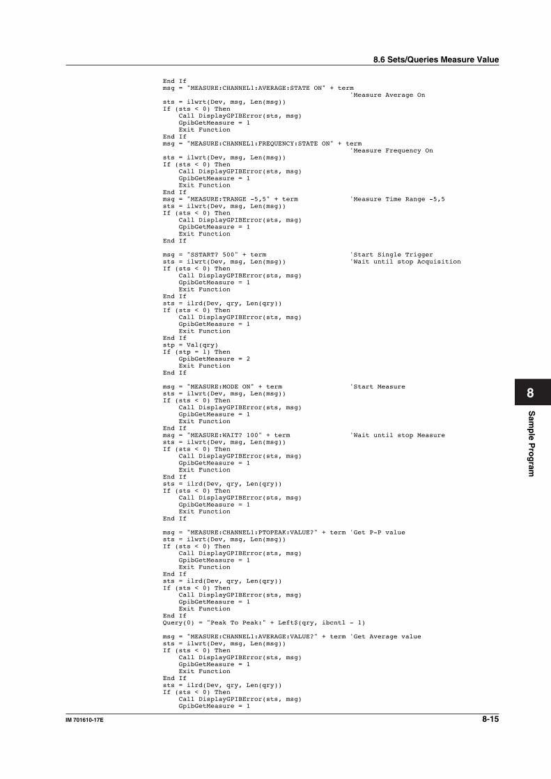
Sam
ple P
rog
ram
8-15IM 701610-17E
8
End If msg = "MEASURE:CHANNEL1:AVERAGE:STATE ON" + term 'Measure Average On sts = ilwrt(Dev, msg, Len(msg)) If (sts < 0) Then Call DisplayGPIBError(sts, msg) GpibGetMeasure = 1 Exit Function End If msg = "MEASURE:CHANNEL1:FREQUENCY:STATE ON" + term 'Measure Frequency On sts = ilwrt(Dev, msg, Len(msg)) If (sts < 0) Then Call DisplayGPIBError(sts, msg) GpibGetMeasure = 1 Exit Function End If msg = "MEASURE:TRANGE -5,5" + term 'Measure Time Range -5,5 sts = ilwrt(Dev, msg, Len(msg)) If (sts < 0) Then Call DisplayGPIBError(sts, msg) GpibGetMeasure = 1 Exit Function End If
msg = "SSTART? 500" + term 'Start Single Trigger sts = ilwrt(Dev, msg, Len(msg)) 'Wait until stop Acquisition If (sts < 0) Then Call DisplayGPIBError(sts, msg) GpibGetMeasure = 1 Exit Function End If sts = ilrd(Dev, qry, Len(qry)) If (sts < 0) Then Call DisplayGPIBError(sts, msg) GpibGetMeasure = 1 Exit Function End If stp = Val(qry) If (stp = 1) Then GpibGetMeasure = 2 Exit Function End If
msg = "MEASURE:MODE ON" + term 'Start Measure sts = ilwrt(Dev, msg, Len(msg)) If (sts < 0) Then Call DisplayGPIBError(sts, msg) GpibGetMeasure = 1 Exit Function End If msg = "MEASURE:WAIT? 100" + term 'Wait until stop Measure sts = ilwrt(Dev, msg, Len(msg)) If (sts < 0) Then Call DisplayGPIBError(sts, msg) GpibGetMeasure = 1 Exit Function End If sts = ilrd(Dev, qry, Len(qry)) If (sts < 0) Then Call DisplayGPIBError(sts, msg) GpibGetMeasure = 1 Exit Function End If
msg = "MEASURE:CHANNEL1:PTOPEAK:VALUE?" + term 'Get P-P value sts = ilwrt(Dev, msg, Len(msg)) If (sts < 0) Then Call DisplayGPIBError(sts, msg) GpibGetMeasure = 1 Exit Function End If sts = ilrd(Dev, qry, Len(qry)) If (sts < 0) Then Call DisplayGPIBError(sts, msg) GpibGetMeasure = 1 Exit Function End If Query(0) = "Peak To Peak:" + Left$(qry, ibcntl - 1)
msg = "MEASURE:CHANNEL1:AVERAGE:VALUE?" + term 'Get Average value sts = ilwrt(Dev, msg, Len(msg)) If (sts < 0) Then Call DisplayGPIBError(sts, msg) GpibGetMeasure = 1 Exit Function End If sts = ilrd(Dev, qry, Len(qry)) If (sts < 0) Then Call DisplayGPIBError(sts, msg) GpibGetMeasure = 1
8.6 Sets/Queries Measure Value
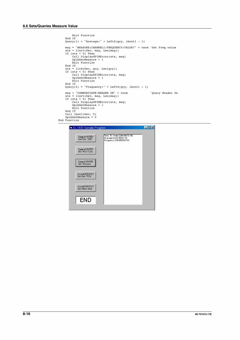
8-16 IM 701610-17E
Exit Function End If Query(1) = "Average:" + Left$(qry, ibcntl - 1)
msg = "MEASURE:CHANNEL1:FREQUENCY:VALUE?" + term 'Get Freq value sts = ilwrt(Dev, msg, Len(msg)) If (sts < 0) Then Call DisplayGPIBError(sts, msg) GpibGetMeasure = 1 Exit Function End If sts = ilrd(Dev, qry, Len(qry)) If (sts < 0) Then Call DisplayGPIBError(sts, msg) GpibGetMeasure = 1 Exit Function End If Query(2) = "Frequency:" + Left$(qry, ibcntl - 1)
msg = "COMMUNICATE:HEADER ON" + term 'Query Header On sts = ilwrt(Dev, msg, Len(msg)) If (sts < 0) Then Call DisplayGPIBError(sts, msg) GpibGetMeasure = 1 Exit Function End If Call ibonl(Dev, 0) GpibGetMeasure = 0End Function----------------------------------------------------------------------------------------
8.6 Sets/Queries Measure Value
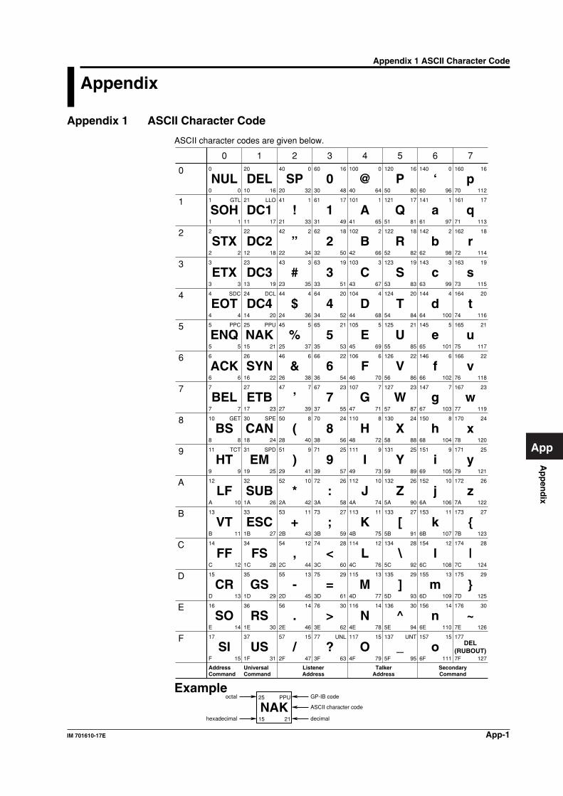
Ap
pen
dix
App-1IM 701610-17E
App
Appendix
Appendix 1 ASCII Character Code
ASCII character codes are given below.
0
1
2
3
4
5
6
7
10
11
12
13
14
15
16
17
NUL
SOH
STX
ETX
EOT
ENQ
ACK
BEL
BS
HT
LF
VT
FF
CR
SO
SI
20
21
22
23
24
25
26
27
30
31
32
33
34
35
36
37
40
41
42
43
44
45
46
47
50
51
52
53
54
55
56
57
60
61
62
63
64
65
66
67
70
71
72
73
74
75
76
77
100
101
102
103
104
105
106
107
110
111
112
113
114
115
116
117
120
121
122
123
124
125
126
127
130
131
132
133
134
135
136
137
140
141
142
143
144
145
146
147
150
151
152
153
154
155
156
157
160
161
162
163
164
165
166
167
170
171
172
173
174
175
176
177
0
1
2
3
4
5
6
7
8
9
A
B
C
D
E
F
0
1
2
3
4
5
6
7
8
9
A
B
C
D
E
F
10
11
12
13
14
15
16
17
18
19
1A
1B
1C
1D
1E
1F
20
21
22
23
24
25
26
27
28
29
2A
2B
2C
2D
2E
2F
30
31
32
33
34
35
36
37
38
39
3A
3B
3C
3D
3E
3F
40
41
42
43
44
45
46
47
48
49
4A
4B
4C
4D
4E
4F
50
51
52
53
54
55
56
57
58
59
5A
5B
5C
5D
5E
5F
60
61
62
63
64
65
66
67
68
69
6A
6B
6C
6D
6E
6F
70
71
72
73
74
75
76
77
78
79
7A
7B
7C
7D
7E
7F
0
1
2
3
4
5
6
7
8
9
10
11
12
13
14
15
16
17
18
19
20
21
22
23
24
25
26
27
28
29
30
31
32
33
34
35
36
37
38
39
40
41
42
43
44
45
46
47
48
49
50
51
52
53
54
55
56
57
58
59
60
61
62
63
64
65
66
67
68
69
70
71
72
73
74
75
76
77
78
79
80
81
82
83
84
85
86
87
88
89
90
91
92
93
94
95
96
97
98
99
100
101
102
103
104
105
106
107
108
109
110
111
112
113
114
115
116
117
118
119
120
121
122
123
124
125
126
127
GTL
SDC
PPC
GET
TCT
LLO
DCL
PPU
SPE
SPD
0
1
2
3
4
5
6
7
8
9
10
11
12
13
14
15
16
17
18
19
20
21
22
23
24
25
26
27
28
29
30
UNL
DEL
DC1
DC2
DC3
DC4
NAK
SYN
ETB
CAN
EM
SUB
ESC
FS
GS
RS
US
SP
!
”
#
$
%
&
’
(
)
*
+
,
-
.
/
0
1
2
3
4
5
6
7
8
9
:
;
<
=
>
?
@
A
B
C
D
E
F
G
H
I
J
K
L
M
N
O
P
Q
R
S
T
U
V
W
X
Y
Z
[
\
]
^
_
‘
a
b
c
d
e
f
g
h
i
j
k
l
m
n
o
p
q
r
s
t
u
v
w
x
y
z
|
~
DEL(RUBOUT)
0
1
2
3
4
5
6
7
8
9
10
11
12
13
14
15
16
17
18
19
20
21
22
23
24
25
26
27
28
29
30
UNT
0
1
2
3
4
5
6
7
8
9
10
11
12
13
14
15
16
17
18
19
20
21
22
23
24
25
26
27
28
29
30
AddressCommand
UniversalCommand
ListenerAddress
TalkerAddress
SecondaryCommand
25
15 21
PPU
NAKoctal
hexadecimal
GP-IB code
decimal
ASCII character code
Example
0 1 2 3 4 5 6 7
Appendix 1 ASCII Character Code
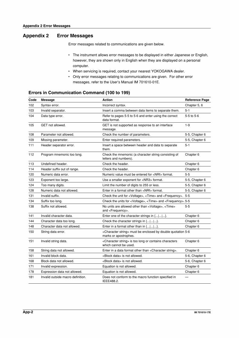
App-2 IM 701610-17E
Appendix 2 Error Messages
Error messages related to communications are given below.
• The instrument allows error messages to be displayed in either Japanese or English,
however, they are shown only in English when they are displayed on a personal
computer.
• When servicing is required, contact your nearest YOKOGAWA dealer.
• Only error messages relating to communications are given. For other error
messages, refer to the User’s Manual IM 701610-01E.
Errors in Communication Command (100 to 199)
Code Message Action Reference Page
102 Syntax error. Incorrect syntax. Chapter 5, 6
103 Invalid separator. Insert a comma between data items to separate them. 5-1
104 Data type error. Refer to pages 5-5 to 5-6 and enter using the correct 5-5 to 5-6data format.
105 GET not allowed. GET is not supported as response to an interface 1-9message.
108 Parameter not allowed. Check the number of parameters. 5-5, Chapter 6
109 Missing parameter. Enter required parameters. 5-5, Chapter 6
111 Header separator error. Insert a space between header and data to separate 5-1them.
112 Program mnemonic too long. Check the mnemonic (a character string consisting of Chapter 6letters and numbers).
113 Undefined header. Check the header. Chapter 6
114 Header suffix out of range. Check the header. Chapter 6
120 Numeric data error. Numeric value must be entered for <NRf> format. 5-5
123 Exponent too large. Use a smaller exponent for <NR3> format. 5-5, Chapter 6
124 Too many digits. Limit the number of digits to 255 or less. 5-5, Chapter 6
128 Numeric data not allowed. Enter in a format other than <NRf> format. 5-5, Chapter 6
131 Invalid suffix. Check the unit for <Voltage>, <Time> and <Frequency>. 5-5
134 Suffix too long. Check the units for <Voltage>, <Time> and <Frequency>. 5-5
138 Suffix not allowed. No units are allowed other than <Voltage>, <Time> 5-5and <Frequency>.
141 Invalid character data. Enter one of the character strings in ...|...|.... Chapter 6
144 Character data too long. Check the character strings in ...|...|.... Chapter 6
148 Character data not allowed. Enter in a format other than in ...|...|.... Chapter 6
150 String data error. <Character string> must be enclosed by double quotation 5-6marks or apostrophes.
151 Invalid string data. <Character string> is too long or contains characters Chapter 6which cannot be used.
158 String data not allowed. Enter in a data format other than <Character string>. Chapter 6
161 Invalid block data. <Block data> is not allowed. 5-6, Chapter 6
168 Block data not allowed. <Block data> is not allowed. 5-6, Chapter 6
171 Invalid expression. Equation is not allowed. Chapter 6
178 Expression data not allowed. Equation is not allowed. Chapter 6
181 Invalid outside macro definition. Does not conform to the macro function specified in —IEEE488.2.
Appendix 2 Error Messages
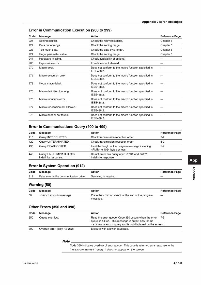
Ap
pen
dix
App-3IM 701610-17E
App
Error in Communication Execution (200 to 299)
Code Message Action Reference Page
221 Setting conflict. Check the relevant setting. Chapter 6
222 Data out of range. Check the setting range. Chapter 6
223 Too much data. Check the data byte length. Chapter 6
224 Illegal parameter value. Check the setting range. Chapter 6
241 Hardware missing. Check availability of options. —
260 Expression error. Equation is not allowed. —
270 Macro error. Does not conform to the macro function specified in —IEEE488.2.
272 Macro execution error. Does not conform to the macro function specified in —IEEE488.2.
273 Illegal macro label. Does not conform to the macro function specified in —IEEE488.2.
275 Macro definition too long. Does not conform to the macro function specified in —IEEE488.2.
276 Macro recursion error. Does not conform to the macro function specified in —IEEE488.2.
277 Macro redefinition not allowed. Does not conform to the macro function specified in —IEEE488.2.
278 Macro header not found. Does not conform to the macro function specified in —IEEE488.2.
Error in Communications Query (400 to 499)
Code Message Action Reference Page
410 Query INTERRUPTED. Check transmission/reception order. 5-2
420 Query UNTERMINATED. Check transmission/reception order. 5-2
430 Query DEADLOCKED. Limit the length of the program message including 5-2<PMT> to 1024 bytes or less.
440 Query UNTERMINATED after Do not enter any query after *IDN? and *OPT?. —indefinite response. indefinite response
Error in System Operation (912)
Code Message Action Reference Page
912 Fatal error in the communication driver. Servicing is required. —
Warning (50)
Code Message Action Reference Page
50 *OPC/? exists in message. Place the *OPC or *OPC? at the end of the program —message.
Other Errors (350 and 390)
Code Message Action Reference Page
350 Queue overflow. Read the error queue. Code 350 occurs when the error 7-5queue is full up. This message is output only for the:STATus:ERRor? query and is not displayed on the screen.
390 Overrun error. (only RS-232) Execute with a lower baud rate. —
NoteCode 350 indicates overflow of error queue. This code is returned as a response to the
":STATus:ERRor?" query; it does not appear on the screen.
Appendix 2 Error Messages
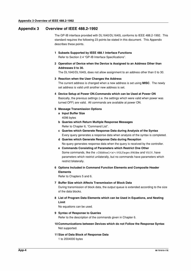
App-4 IM 701610-17E
Appendix 3 Overview of IEEE 488.2-1992
The GP-IB interface provided with DL1640/DL1640L conforms to IEEE 488.2-1992. This
standard requires the following 23 points be stated in this document. This Appendix
describes these points.
1 Subsets Supported by IEEE 488.1 Interface Functions
Refer to Section 2.4 “GP-IB Interface Specifications”.
2 Operation of Device when the Device is Assigned to an Address Other than
Addresses 0 to 30.
The DL1640/DL1640L does not allow assignment to an address other than 0 to 30.
3 Reaction when the User Changes the Address
The current address is changed when a new address is set using MISC. The newly
set address is valid until another new address is set.
4 Device Setup at Power ON.Commands which can be Used at Power ON
Basically, the previous settings (i.e. the settings which were valid when power was
turned OFF) are valid. All commands are available at power ON.
5 Message Transmission Options
a Input Buffer Size
4096 bytes
b Queries which Return Multiple Response Messages
Refer to Chapter 6, “Command List”.
c Queries which Generate Response Data during Analysis of the Syntax
Every query generates a response data when analysis of the syntax is completed.
d Queries which Generate Response Data during Reception
No query generates response data when the query is received by the controller.
e Commands Consisting of Parameters which Restrict One Other
Some commands, like the :CHANnel<x>:VOLTage:PROBe and VDIV, have
parameters which restrict unilaterally, but no commands have parameters which
restrict bilaterally.
6 Options Included in Command Function Elements and Composite Header
Elements
Refer to Chapters 5 and 6.
7 Buffer Size which Affects Transmission of Block Data
During transmission of block data, the output queue is extended according to the size
of the data blocks.
8 List of Program Data Elements which can be Used in Equations, and Nesting
Limit
No equations can be used.
9 Syntax of Response to Queries
Refer to the description of the commands given in Chapter 6.
10 Communications between Devices which do not Follow the Response Syntax
Not supported.
11 Size of Data Block of Response Data
1 to 2004000 bytes
Appendix 3 Overview of IEEE 488.2-1992
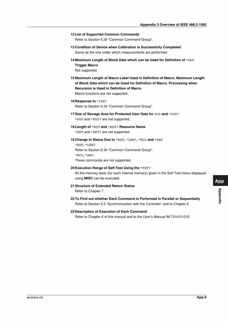
Ap
pen
dix
App-5IM 701610-17E
App
12 List of Supported Common Commands
Refer to Section 6.34 “Common Command Group”.
13 Condition of Device when Calibration is Successfully Completed
Same as the one under which measurements are performed
14 Maximum Length of Block Data which can be Used for Definition of *DDT
Trigger Macro
Not supported
15 Maximum Length of Macro Label Used in Definition of Macro, Maximum Length
of Block Data which can be Used for Definition of Macro, Processing when
Recursion is Used in Definition of Macro
Macro functions are not supported.
16 Response to *IDN?
Refer to Section 6.34 “Common Command Group”.
17 Size of Storage Area for Protected User Data for PUD and *PUD?
*PUD and *PUD? are not supported.
18 Length of *RDT and *RDT? Resource Name
*RDT and *RDT? are not supported.
19 Change in Status Due to *RST, *LRN?, *RCL and *SAV
*RST, *LRN?
Refer to Section 6.34 “Common Command Group”.
*RCL, *SAV
These commands are not supported.
20 Execution Range of Self-Test Using the *TST?
All the memory tests (for each internal memory) given in the Self Test menu displayed
using MISC can be executed.
21 Structure of Extended Return Status
Refer to Chapter 7.
22 To Find out whether Each Command is Performed in Parallel or Sequentially
Refer to Section 5.5 “Synchronization with the Controller” and to Chapter 6.
23 Description of Execution of Each Command
Refer to Chapter 6 of this manual and to the User’s Manual IM 701610-01E.
Appendix 3 Overview of IEEE 488.2-1992
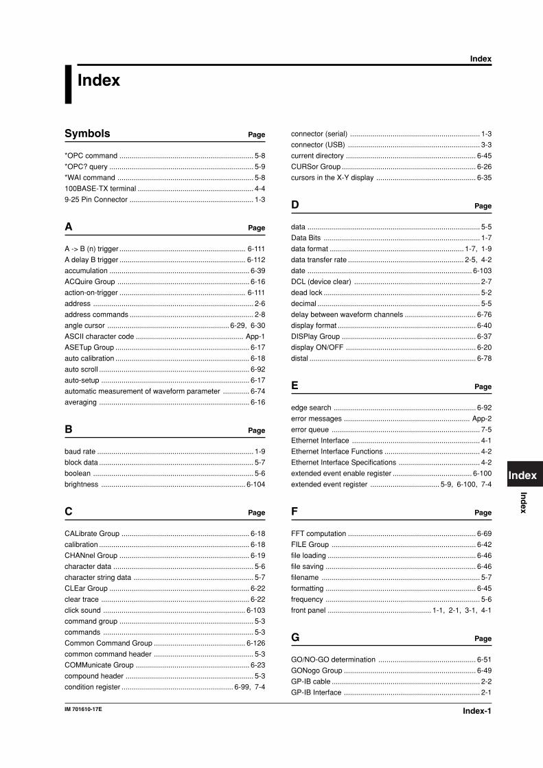
Index-1IM 701610-17E
Ind
ex
Index
Index
connector (serial) ................................................................ 1-3
connector (USB) ................................................................. 3-3
current directory ................................................................ 6-45
CURSor Group .................................................................. 6-26
cursors in the X-Y display ................................................. 6-35
D Page
data ..................................................................................... 5-5
Data Bits ............................................................................. 1-7
data format .................................................................. 1-7, 1-9
data transfer rate ......................................................... 2-5, 4-2
date ................................................................................. 6-103
DCL (device clear) .............................................................. 2-7
dead lock ............................................................................. 5-2
decimal ................................................................................ 5-5
delay between waveform channels ................................... 6-76
display format .................................................................... 6-40
DISPlay Group .................................................................. 6-37
display ON/OFF ................................................................ 6-20
distal .................................................................................. 6-78
E Page
edge search ...................................................................... 6-92
error messages .............................................................. App-2
error queue ......................................................................... 7-5
Ethernet Interface ............................................................... 4-1
Ethernet Interface Functions ............................................... 4-2
Ethernet Interface Specifications ........................................ 4-2
extended event enable register ....................................... 6-100
extended event register .................................. 5-9, 6-100, 7-4
F Page
FFT computation ............................................................... 6-69
FILE Group ....................................................................... 6-42
file loading ......................................................................... 6-46
file saving .......................................................................... 6-46
filename .............................................................................. 5-7
formatting .......................................................................... 6-45
frequency ............................................................................ 5-6
front panel ................................................... 1-1, 2-1, 3-1, 4-1
G Page
GO/NO-GO determination ................................................ 6-51
GONogo Group ................................................................. 6-49
GP-IB cable ......................................................................... 2-2
GP-IB Interface ................................................................... 2-1
Symbols Page
*OPC command .................................................................. 5-8
*OPC? query ....................................................................... 5-9
*WAI command ................................................................... 5-8
100BASE-TX terminal ......................................................... 4-4
9-25 Pin Connector ............................................................. 1-3
A Page
A -> B (n) trigger .............................................................. 6-111
A delay B trigger .............................................................. 6-112
accumulation ..................................................................... 6-39
ACQuire Group ................................................................. 6-16
action-on-trigger .............................................................. 6-111
address ............................................................................... 2-6
address commands ............................................................. 2-8
angle cursor ............................................................ 6-29, 6-30
ASCII character code ..................................................... App-1
ASETup Group .................................................................. 6-17
auto calibration .................................................................. 6-18
auto scroll .......................................................................... 6-92
auto-setup ......................................................................... 6-17
automatic measurement of waveform parameter ............. 6-74
averaging .......................................................................... 6-16
B Page
baud rate ............................................................................. 1-9
block data ............................................................................ 5-7
boolean ............................................................................... 5-6
brightness ....................................................................... 6-104
C Page
CALibrate Group ............................................................... 6-18
calibration .......................................................................... 6-18
CHANnel Group ................................................................ 6-19
character data ..................................................................... 5-6
character string data ........................................................... 5-7
CLEar Group ..................................................................... 6-22
clear trace ......................................................................... 6-22
click sound ...................................................................... 6-103
command group .................................................................. 5-3
commands .......................................................................... 5-3
Common Command Group ............................................. 6-126
common command header ................................................. 5-3
COMMunicate Group ........................................................ 6-23
compound header ............................................................... 5-3
condition register ....................................................... 6-99, 7-4
Index
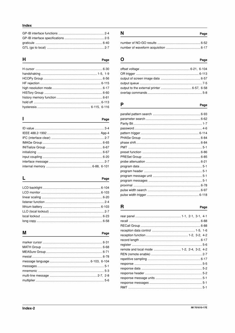
Index-2 IM 701610-17E
GP-IB interface functions .................................................... 2-4
GP-IB interface specifications ............................................. 2-5
graticule ............................................................................ 6-40
GTL (go to local) ................................................................. 2-7
H Page
H cursor ............................................................................ 6-30
handshaking ................................................................ 1-5, 1-9
HCOPy Group ................................................................... 6-56
HF rejection ..................................................................... 6-115
high resolution mode ......................................................... 6-17
HISTory Group .................................................................. 6-60
history memory function .................................................... 6-61
hold off ............................................................................ 6-113
hysteresis ............................................................ 6-115, 6-116
I Page
ID value ............................................................................... 3-4
IEEE 488.2-1992 ............................................................ App-4
IFC (interface clear) ............................................................ 2-7
IMAGe Group .................................................................... 6-65
INITialize Group ................................................................ 6-67
initializing .......................................................................... 6-67
input coupling .................................................................... 6-20
interface message ............................................................... 2-7
internal memory .................................................... 6-88, 6-101
L Page
LCD backlight .................................................................. 6-104
LCD monitor .................................................................... 6-103
linear scaling ..................................................................... 6-20
listener function ................................................................... 2-4
lithium battery .................................................................. 6-103
LLO (local lockout) .............................................................. 2-7
local lockout ...................................................................... 6-23
long copy ........................................................................... 6-58
M Page
marker cursor .................................................................... 6-31
MATH Group ..................................................................... 6-68
MEASure Group ................................................................ 6-71
mesial ................................................................................ 6-78
message language .............................................. 6-103, 6-104
messages ............................................................................ 5-1
mnemonic ........................................................................... 5-3
multi-line message ...................................................... 2-7, 2-8
multiplier .............................................................................. 5-6
N Page
number of NO-GO results ................................................. 6-52
number of waveform acquisition ....................................... 6-17
O Page
offset voltage ......................................................... 6-21, 6-104
OR trigger ....................................................................... 6-113
output of screen image data ............................................. 6-57
output queue ....................................................................... 7-5
output to the external printer ................................... 6-57, 6-58
overlap commands .............................................................. 5-8
P Page
parallel pattern search ...................................................... 6-93
parameter search .............................................................. 6-62
Parity Bit .............................................................................. 1-7
password ............................................................................. 4-6
pattern trigger .................................................................. 6-114
PHASe Group ................................................................... 6-84
phase shift ......................................................................... 6-84
PMT .................................................................................... 5-1
preset function .................................................................. 6-86
PRESet Group .................................................................. 6-85
probe attenuation .............................................................. 6-21
program data ....................................................................... 5-1
program header .................................................................. 5-1
program message unit ........................................................ 5-1
program messages ............................................................. 5-1
proximal ............................................................................ 6-78
pulse width search ............................................................ 6-97
pulse width trigger ........................................................... 6-118
R Page
rear panel .................................................... 1-1, 2-1, 3-1, 4-1
recall ................................................................................. 6-88
RECall Group .................................................................... 6-88
reception data control ................................................. 1-5, 1-6
reception function ................................................ 1-2, 3-2, 4-2
record length ..................................................................... 6-17
register ................................................................................ 5-6
remote and local mode ............................... 1-2, 2-4, 3-2, 4-2
REN (remote enable) .......................................................... 2-7
repetitive sampling ............................................................ 6-17
response ............................................................................. 5-5
response data ..................................................................... 5-2
response header ................................................................. 5-2
response message units ..................................................... 5-1
response messages ............................................................ 5-1
RMT .................................................................................... 5-1
Index
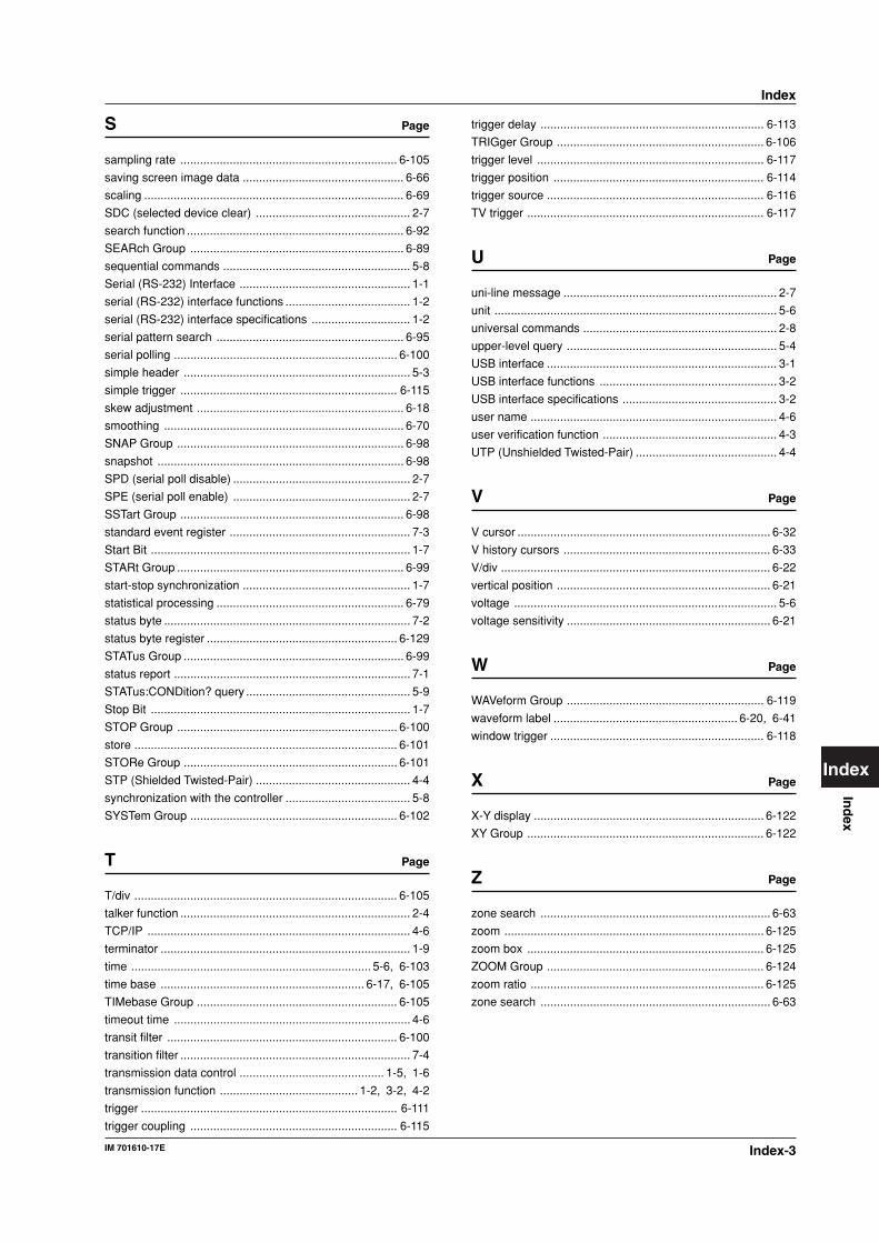
Index-3IM 701610-17E
Ind
ex
Index
Index
S Page
sampling rate .................................................................. 6-105
saving screen image data ................................................. 6-66
scaling ............................................................................... 6-69
SDC (selected device clear) ............................................... 2-7
search function .................................................................. 6-92
SEARch Group ................................................................. 6-89
sequential commands ......................................................... 5-8
Serial (RS-232) Interface .................................................... 1-1
serial (RS-232) interface functions ...................................... 1-2
serial (RS-232) interface specifications .............................. 1-2
serial pattern search ......................................................... 6-95
serial polling .................................................................... 6-100
simple header ..................................................................... 5-3
simple trigger .................................................................. 6-115
skew adjustment ............................................................... 6-18
smoothing ......................................................................... 6-70
SNAP Group ..................................................................... 6-98
snapshot ........................................................................... 6-98
SPD (serial poll disable) ...................................................... 2-7
SPE (serial poll enable) ...................................................... 2-7
SSTart Group .................................................................... 6-98
standard event register ....................................................... 7-3
Start Bit ............................................................................... 1-7
STARt Group ..................................................................... 6-99
start-stop synchronization ................................................... 1-7
statistical processing ......................................................... 6-79
status byte ........................................................................... 7-2
status byte register .......................................................... 6-129
STATus Group ................................................................... 6-99
status report ........................................................................ 7-1
STATus:CONDition? query .................................................. 5-9
Stop Bit ............................................................................... 1-7
STOP Group ................................................................... 6-100
store ................................................................................ 6-101
STORe Group ................................................................. 6-101
STP (Shielded Twisted-Pair) ............................................... 4-4
synchronization with the controller ...................................... 5-8
SYSTem Group ............................................................... 6-102
T Page
T/div ................................................................................ 6-105
talker function ...................................................................... 2-4
TCP/IP ................................................................................ 4-6
terminator ............................................................................ 1-9
time ......................................................................... 5-6, 6-103
time base .............................................................. 6-17, 6-105
TIMebase Group ............................................................. 6-105
timeout time ........................................................................ 4-6
transit filter ...................................................................... 6-100
transition filter ...................................................................... 7-4
transmission data control ............................................ 1-5, 1-6
transmission function .......................................... 1-2, 3-2, 4-2
trigger .............................................................................. 6-111
trigger coupling ............................................................... 6-115
trigger delay .................................................................... 6-113
TRIGger Group ............................................................... 6-106
trigger level ..................................................................... 6-117
trigger position ................................................................ 6-114
trigger source .................................................................. 6-116
TV trigger ........................................................................ 6-117
U Page
uni-line message ................................................................. 2-7
unit ...................................................................................... 5-6
universal commands ........................................................... 2-8
upper-level query ................................................................ 5-4
USB interface ...................................................................... 3-1
USB interface functions ...................................................... 3-2
USB interface specifications ............................................... 3-2
user name ........................................................................... 4-6
user verification function ..................................................... 4-3
UTP (Unshielded Twisted-Pair) ........................................... 4-4
V Page
V cursor ............................................................................. 6-32
V history cursors ............................................................... 6-33
V/div .................................................................................. 6-22
vertical position ................................................................. 6-21
voltage ................................................................................ 5-6
voltage sensitivity .............................................................. 6-21
W Page
WAVeform Group ............................................................ 6-119
waveform label ........................................................ 6-20, 6-41
window trigger ................................................................. 6-118
X Page
X-Y display ...................................................................... 6-122
XY Group ........................................................................ 6-122
Z Page
zone search ...................................................................... 6-63
zoom ............................................................................... 6-125
zoom box ........................................................................ 6-125
ZOOM Group .................................................................. 6-124
zoom ratio ....................................................................... 6-125
zone search ...................................................................... 6-63