Embed Size (px)
Citation preview

ww
w.y
oko
ga
wa
.co
m/t
m/
Su
bsc
rib
e to
"N
ewsw
ave"
ou
r fr
ee e
-mai
l new
slet
ter
DL1740EL
Up to 1 GS/s, 8 MW Memory 350MHz Analog Bandwidth : DL1735E
500MHz Analog Bandwidth : DL1720E, DL1740E, DL1740EL PC Card Interface USB Storage I2C & SPI Bus Trigger and Analysis
1GS/s8MW1GS/s8MWMax. Memory
Max. Sampling Rate
DL1700E SeriesDigital OscilloscopesDL1720E/DL1735E/DL1740E/DL1740EL
Bulletin 7017-40E
350MHz Analog Bandwidth
DL1735E
NEW!!
2
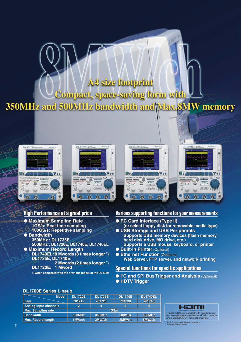
Various supporting functions for your measurements PC Card Interface (Type II)
(or select floppy disk for removable media type) USB Storage and USB Peripherals
Supports USB memory devices (flash memory,hard disk drive, MO drive, etc.)Supports a USB mouse, keyboard, or printer
Built-In Printer (Optional) Ethernet Function (Optional)
Web Server, FTP server, and network printing
Special functions for specific applications I2C and SPI Bus Trigger and Analysis (Optional) HDTV Trigger
High Performance at a great price Maximum Sampling Rate
1GS/s: Real-time sampling100GS/s: Repetitive sampling
Bandwidth350MHz : DL1735E500MHz : DL1720E, DL1740E, DL1740EL
Maximum Record LengthDL1740EL: 8 Mwords (8 times longer 1)DL1735E, DL1740E:
2 Mwords (2 times longer 1)DL1720E: 1 Mword1. When compared with the previous model of the DL1740
Various supporting functions for your measurements PC Card Interface (Type II)
(or select floppy disk for removable media type) USB Storage and USB Peripherals
Supports USB memory devices (flash memory,hard disk drive, MO drive, etc.)Supports a USB mouse, keyboard, or printer
Built-In Printer (Optional) Ethernet Function (Optional)
Web Server, FTP server, and network printing
Special functions for specific applications I2C and SPI Bus Trigger and Analysis (Optional) HDTV Trigger
DL1700E Series LineupModel DL1720E DL1735E DL1740E DL1740EL
Item 701715 701725 701730 701740Analog input channels 2 4 4 4Max. Sampling rate 1GS/s Bandwidth 500MHz 350MHz 500MHz 500MHzMax. Record length 1MW/ch 2MW/ch 2MW/ch 8MW/ch
DL1700E Series LineupModel DL1720E DL1735E DL1740E DL1740EL
Item 701715 701725 701730 701740Analog input channels 2 4 4 4Max. Sampling rate 1GS/s Bandwidth 500MHz 350MHz 500MHz 500MHzMax. Record length 1MW/ch 2MW/ch 2MW/ch 8MW/ch
The DL1700E series with the I2C analysis func-tion are officially accredited for HDMI*1 compli-ance testing(DDC*2 protocol analysis).
*1: High-Definition Multimedia Interface*2: Display Data Channel
3
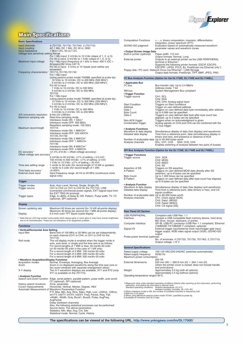
Smart Search Function for Effective Access to the Data You Need
"I want to find the serial data with a particular serialpattern", "I need to search for surge pulses of less than 30ns", "I want to only extract waveforms that occasionallyovershoot by an excessive amount".......As data volumeincreases, it becomes more important to be able to searchfor target phenomena efficiently. The Smart Searchfunction automatically detects serial patterns, pulse widths,rising edges, falling edges, and other phenomena in thecaptured waveform data. These phenomena are thendisplayed in the zoom screen. Smart Search willsignificantly improve the efficiency of your developmentand evaluation work.
When an abnormal signal is displayed on the screen, does it disappear before you can press the STOP key?
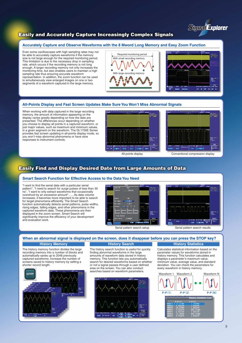
Even some oscilloscopes with high sampling rates may notbe able to accurately capture waveforms if the memorysize is not large enough for the required monitoring period.This limitation is due to the necessary drop in samplingrate, which occurs if the recording memory is not longenough. A larger recording memory not only increases themonitoring time, but also enables users to maintain a highsampling rate thus ensuring accurate waveformrepresentation. In addition, the zoom function can be usedto simultaneously view enlarged images on one or twosegments of a waveform captured in the large memory.
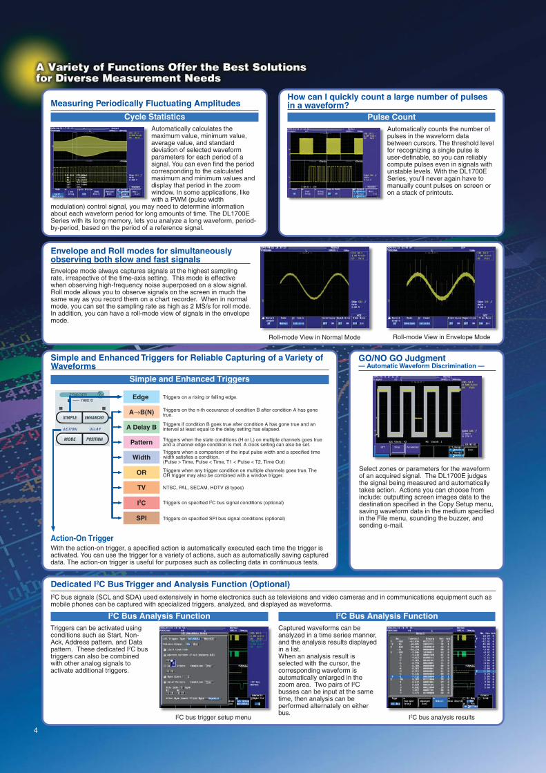
All-Points Display and Fast Screen Updates Make Sure You Won’t Miss Abnormal Signals
When working with data captured in the large recordingmemory, the amount of information appearing on thedisplay varies greatly depending on how the data arepresented. The differences occur depending on whetheryou choose to display all points in a captured waveform, orjust major values, such as maximum and minimum values,in a given segment on the waveform. The DL1700E Seriesprovides fast screen updating in all-points display mode, soyou won’t miss abnormal phenomena or have slowresponses to instrument controls.
With small recording memory
With large recording memory
Required monitoring period
Accurately Capture and Observe Waveforms with the 8 Mword Long Memory and Easy Zoom Function
P-P(1) P-P(2) P-P(N)
Waveform 1 Waveform 2 Waveform N
History MemoryThe history memory function divides the largerecording memory into a number of blocks andautomatically saves up to 2048 previouslycaptured waveforms. Increase the number ofscreens saved to history memory by setting ashorter record length.
History SearchThe history search function is useful for quicklyfinding abnormal waveforms in the largeamounts of waveform data stored in historymemory. This function lets you automaticallysearch for desired waveforms based on whetheror not a signal passes through a user-definedarea on the screen. You can also conductsearches based on waveform parameters.
History StatisticsCalculates statistical information based on theparameter values for waveforms stored inhistory memory. This function calculates anddisplays a parameter’s maximum value,minimum value, average value, and standarddeviation. You can check the parameters forevery waveform in history memory.
Serial pattern search resultsSerial pattern search setup
Conventional compression displayAll-points display
4
How can I quickly count a large number of pulsesin a waveform?
Pulse CountAutomatically counts the number ofpulses in the waveform databetween cursors. The threshold levelfor recognizing a single pulse isuser-definable, so you can reliablycompute pulses even in signals withunstable levels. With the DL1700ESeries, you’ll never again have tomanually count pulses on screen oron a stack of printouts.
Envelope and Roll modes for simultaneouslyobserving both slow and fast signalsEnvelope mode always captures signals at the highest samplingrate, irrespective of the time-axis setting. This mode is effectivewhen observing high-frequency noise superposed on a slow signal.Roll mode allows you to observe signals on the screen in much thesame way as you record them on a chart recorder. When in normalmode, you can set the sampling rate as high as 2 MS/s for roll mode.In addition, you can have a roll-mode view of signals in the envelopemode.
Dedicated I2C Bus Trigger and Analysis Function (Optional)I2C bus signals (SCL and SDA) used extensively in home electronics such as televisions and video cameras and in communications equipment such asmobile phones can be captured with specialized triggers, analyzed, and displayed as waveforms.
I2C Bus Analysis FunctionTriggers can be activated usingconditions such as Start, Non-Ack, Address pattern, and Datapattern. These dedicated I2C bustriggers can also be combinedwith other analog signals toactivate additional triggers.
I2C Bus Analysis FunctionCaptured waveforms can beanalyzed in a time series manner,and the analysis results displayedin a list.When an analysis result isselected with the cursor, thecorresponding waveform isautomatically enlarged in thezoom area. Two pairs of I2Cbusses can be input at the sametime, then analysis can beperformed alternately on eitherbus.
Cycle StatisticsAutomatically calculates themaximum value, minimum value,average value, and standarddeviation of selected waveformparameters for each period of asignal. You can even find the periodcorresponding to the calculatedmaximum and minimum values anddisplay that period in the zoomwindow. In some applications, likewith a PWM (pulse width
modulation) control signal, you may need to determine informationabout each waveform period for long amounts of time. The DL1700ESeries with its long memory, lets you analyze a long waveform, period-by-period, based on the period of a reference signal.
Measuring Periodically Fluctuating Amplitudes
Roll-mode View in Envelope ModeRoll-mode View in Normal Mode
I2C bus analysis resultsI2C bus trigger setup menu
Action-On TriggerWith the action-on trigger, a specified action is automatically executed each time the trigger isactivated. You can use the trigger for a variety of actions, such as automatically saving captureddata. The action-on trigger is useful for purposes such as collecting data in continuous tests.
Simple and Enhanced Triggers for Reliable Capturing of a Variety ofWaveforms
GO/NO GO Judgment— Automatic Waveform Discrimination —
Simple and Enhanced Triggers
Edge
SPI
I2C
TV
OR
Width
Pattern
A Delay B
A→B(N)
Triggers on a rising or falling edge.
Triggers on the n-th occurance of condition B after condition A has gone true.
Triggers if condition B goes true after condition A has gone true and an interval at least equal to the delay setting has elapsed.
Triggers when the state conditions (H or L) on multiple channels goes true and a channel edge condition is met. A clock setting can also be set.
Triggers when a comparison of the input pulse width and a specified time width satisfies a condition. (Pulse > Time, Pulse < Time, T1 < Pulse < T2, Time Out)
Triggers when any trigger condition on multiple channels goes true. The OR trigger may also be combined with a window trigger.
NTSC, PAL, SECAM, HDTV (8 types)
Triggers on specified I2C bus signal conditions (optional)
Triggers on specified SPI bus signal conditions (optional)
Select zones or parameters for the waveformof an acquired signal. The DL1700E judgesthe signal being measured and automaticallytakes action. Actions you can choose frominclude: outputting screen images data to thedestination specified in the Copy Setup menu,saving waveform data in the medium specifiedin the File menu, sounding the buzzer, andsending e-mail.

5
Dedicated SPI Bus Trigger and Analysis Function (Optional)The SPI data bus is a synchronous 8-bit serial bus used widely for inter-IC and data communications in embedded systems. SPI bus signals can becaptured using the DL1700E dedicated triggers and the waveforms can be analyzed and displayed on the screen.
SPI Bus Trigger FunctionTriggers can be activated by comparing each byte ofMOSI (master output slave input) and MISO (masterinput slave output) data with specified conditions. Youcan trigger on user-defined strings of data from 1 to 8bytes long.
SPI Bus Analysis FunctionData analysis results and SS (slave select) bits can bedisplayed in a list together with the waveforms. Youcan perform a high speed search for a specified MOSIor MISO data pattern (of 1 to 8 bytes) from within all ofthe captured data.
USB
Peripheral DeviceConnections• USB compatible flash memory, hard
drives, or MO drives can be connectedto easily save waveform data andscreen images.
• The DL1700E Series can be completelycontrolled using a USB mouse.
• File names can be entered using a USBkeyboard.
• Connect a USB printer for colorprintouts.
PC Connection• You can create a PC program to
remotely control the DL1700E via USB.This is similar to how you would controloperations via GP-IB.
Ethernet
Web ServerWith an Ethernet connection, you can perform various functions using Internet Explorer.
• FTPEasily copy and paste files fromthe DL1700E's internal storagedevices to connected PC ornetwork drive. The internalstorage device functions as oneof your PC file servers.
• Data CapturePerform actions such aswaveform monitoring, uploadingsettings, and starting/stoppingmeasurements.
• Measurement TrendAutomatically opens Excel, thenperiodically downloads waveformparameter values and graphsthem. Easily monitor parametertrends during extended-periodmeasurements.
• Printing on a NetworkPrinterThe screen image can be printedon a network printer in the sameway as you would print to theinternal printer or a USB printer.
Easily and Quickly Output Images and Data to a Variety of Devices
The COPY key lets you printscreenshots to the built-in printer, aUSB printer, or a network printer.
PC card
USB flash memory
USB hard disk
USB MO
By simply pressing IMAGE SAVE key, you caneasily and quickly save screen image data to thePC card, USB flash memory, MO, or USB harddisk media. Screen image formats include BMP,TIFF, PS, PNG, or JPEG. Thumbnail imagesmake previewing your captured images simple.The thumbnail appears together with the filename, allowing you to confirm, delete, or makespot changes to the image file name.
SPI bus analysis setting screen

6
MATLAB tool kit (701991)The MATLAB tool kit for the DLseries is a plug-in for MATALABsoftware. The toolkit can be usedto control supported DL seriesinstruments using MATLAB or toacquire data from a DL seriesinstrument for use in MATLABvia a communication interface(GP-IB, USB, Ethernet).
You can download a trial version of MATLAB tool kit from YOKOGAWA’s web site at:http://www.yokogawa.com/tm/701991/
Xviewer (701992)Xviewer is a PC softwareapplication designed to work withYokogawa’s DL series digitaloscilloscopes and the DL750series ScopeCorders. Xviewerallows you to display DL-acquired waveform data (usingthe “Viewer” function), performfile transfers, and control DLseries instruments remotely.
You can download a trial version of Xviewer from YOKOGAWA’s web site at:http://www.yokogawa.com/tm/701992/
900 MHz FET probe (700939)Attenuation ratio: 1/10 with 50 Ω load
Input voltage range: ±10 V
50 MHz current probe (701933)Input range: 30Arms
Basic accessories set for the701941 probe(B9852HF)
11 accessories are included in this set. *2
Miniature passive probe (701941)500MHz bandwidth, 1.2m long
Standard accessories: Basic Accessories setB9852HF-see right.
100 MHz current probe (701932)Input range: 30 Arms
10 MHz current probe (701930)Input range: 150 Arms
100 MHz differential probe (700924)
Attenuation ratio: Can be switched between 1/100 and 1/1000
Max. differential allowed voltage: ±350 V/(1/100), ±1400 V/(1/1000)
100 MHz differential probe (701921)
Attenuation ratio: Can be switchedbetween 1/10 and 1/100
Max. differential allowed voltage:±70 V/(1/10), ±700 V/(1/100)
200 MHz differential probe (701922)
Attenuation ratio: 1/10 with 50 Ω load Max. differential allowed voltage: ±20 V
500 MHz differential probe (701920)
Attenuation ratio: 1/10 with 50 Ω load Max. differential allowed voltage: ±12 V
*1: 701941 probes including the basic accessories set are included with the main unit when the /EX2, /EX4 options are specified.*2: The B9852HF contains the following eleven(11) kinds of accessories.
(Insulation cap, IC cap, BNC adapter, Rigid tip, Spring tip (Ø: 0.80 mm), Spring tip (Ø: 0.38 mm), Ground spring, Adjustment tool, Pincher tip, Standard ground lead, Color coding rings)
Probe Power Terminal(Optional)(Two outputs on the 701715)
Power output terminals for accessoryprobes.
Ethernet (Optional)100 BASE-TX/10-BASE-T compliantLets you take advantage of Web Serverand WebDAV functions.
USB-PC ConnectorCompliant with USB Rev. 1.1
USB Peripheral ConnectorsType A connectors: 2Compliant with USB Rev. 1.1Accepts a USB flash memory device, harddrive, MO drive, mouse, keyboard, orprinter.
Trigger OutputOutputs TTL level trigger signal.
RGB Video Signal OutputConnectorOutputs a video signal for viewingwaveforms on an external monitor.
External Trigger Input/ExternalClock Input/Trigger Gate Input(701715 is on the front panel)
Inputs DC to 100 MHz signal for externaltriggering (external trigger input).Inputs clock signal from 40 Hz to 20 MHzfrom exterior (external clock).Trigger occurrence can be controlled usingexternal signal (trigger gate input).
GO/NO-GO Output TerminalUsing the GO/NO-GO function, you canoutput waveform judgment results asTTL level signals.
GP-IB
7The specifications can be viewed at the following URL. http://www.yokogawa.com/tm/DL1700E/
Basic Specifications
Input channels 4 (701725, 701730, 701740) 2 (701715)Input coupling AC 1 MΩ, DC 1 MΩ, DC 50 Ω, GNDInput impedance 1 MΩ±1.0%, 50 Ω±1.0%Voltage axis sensitivity setting Range
For 1 MΩ input: 2 mV/div to 10 V/div (steps of 1, 2, or 5)For 50 Ω input: 2 mV/div to 1 V/div (steps of 1, 2, or 5)
Maximum input voltage For 1 MΩ input (frequency of 1 kHz or less): 400 V (DC +ACpeak)(282 Vrms CAT II)For 50 Ω input: 5 Vrms or 10 Vpeak (and neither areexceeded)
Frequency characteristics 1 701715,701730,701740For 1 MΩ input(using passive probe model 700988; specified at probe tip): 10 V/div to 10 mV/div: DC to 400 MHz (500 MHz4) 5 mV/div to 2 mV/div: DC to 300 MHz (400 MHz4)For 50 Ω input: 1 V/div to 10 mV/div: DC to 500 MHz 5 mV/div to 2 mV/div: DC to 400 MHz701725For 1 MΩ input(using passive probe model 700988; specified at probe tip): 10 V/div to 10 mV/div: DC to 350 MHz (350 MHz4) 5 mV/div to 2 mV/div: DC to 250 MHz (250 MHz4)For 50 Ω input: 1 V/div to 10 mV/div: DC to 350 MHz 5 mV/div to 2 mV/div: DC to 250 MHz
A/D conversion resolution 8 bits (24 LSB/div)Maximum sampling rate Real-time sampling mode
Interleave mode ON: 1 GS/s 2
Interleave mode OFF: 500 MS/sRepetitive sampling mode: 100 GS/s
Maximum record length 701715Interleave mode ON: 1 MW/CH 2
Interleave mode OFF: 500 kW/CH701725,701730Interleave mode ON: 2 MW/CH 2
Interleave mode OFF: 1 MW/CH701740Interleave mode ON: 8 MW/CH 2
Interleave mode OFF: 4 MW/CHDC accuracy 1 ±(1.5% of 8 div + offset voltage accuracy)Offset voltage axis accuracy 1
2 mV/div to 50 mV/div: ±(1% of setting + 0.2 mV)100 mV/div to 500 mV/div: ±(1% of setting +2 mV)1 V/div to 10 V/div: ±(1% of setting + 20 mV)
Time axis setting range 1 ns/div to 50 s/div (for record length of 10 kW or greater)1 ns/div to 5 s/div (for record length of 1 kW)
Time base accuracy 1 ±0.005%External clock input Input frequency range: 40 Hz to 20 MHz (continuous clock
signal only)
Trigger
Trigger modes Auto, Auto Level, Normal, Single, Single (N)Trigger source CH1 to CH4 (or CH1 to CH2 for the 701715), LINE
(connected commercial power signal), EXT (signal input fromthe EXT TRIG IN terminal)
Trigger types Edge, A->B(N), A Delay B, OR, Pattern, Pulse width, TV, I2C(optional), SPI (optional)
Display
Screen updating rate Maximum 60 times per second (for 10 kW all-points display)Maximum 30 times per second (for 1 MW all-points display)
Display 6.4-inch color TFT liquid crystal display
* Note that an LCD may contain some pixels which always glow or never glow or may have uneven brightnessdue to its characteristics. These are not indications of an equipment problem.
Functions
• Vertical/Horizontal Axis SettingInput filter Band limit of 100 MHz or 20 MHz can be set independently
on each channel (CH1 to CH4, or CH1 to CH2 for the701715)
Roll mode The roll display mode is enabled when the trigger mode isauto, auto level, or single and the time axis is as follows:For record lengths of 1 MW or less: 50 ms/div-50 s/div(or 50 ms/div-50 s/div in the case of 1 kW only)For a record length of 2 MW: 100 ms/div-50 s/divFor a record length of 4 MW: 200 ms/div-50 s/divFor a record length of 8 MW: 500 ms/div-50 s/div
• Waveform Acquisition/Display FunctionsAcquisition modes Normal, Envelope, Averaging, Box AverageZoom Zoom in on displayed waveforms along the time axis (one or
two zoom windows with separate enlargement ratios)X-Y display Two X-Y waveform displays are available, XY1 and XY2 (only
XY1 is available on the 701715).• Analysis FunctionSearch and Zoom function Edge, serial pattern, parallel pattern, pulse width, auto scroll,
I2C (optional), SPI (optional)History search functions Zone, parameterCursor measurements Horizontal, Vertical, Marker, Degree, H&VAutomatic Measurement of Waveform Parameters Function
P-P, Max, Min, Avg, Rms, Sdev, High, Low, +OShot, -OShot,Int1TY, Int2TY, Int1XY, Int2XY, Freq, Period, Rise, Fall,+Width, -Width, Duty, Burst1, Burst2, Pulse, AvgFreq,AvgPeriod,Delay (between channels)Also, the following statistical processes can be performedSource items: The above parametersStatistics: Min, Max, Avg, Cnt, SdvStatistical mode: Normal, Cycle, History
Computation Functions +, -, x, binary computation, inversion, differentiation,integration, power spectrum (FFT)
GO/NO-GO judgment Evaluation based on automatically measured waveformparameter values and waveform zones
• Output Screen Image DataBuilt-in printer (optional) Paper width: 112 mm
Output formats: Normal, LongExternal printer Outputs to an external printer via the USB PERIPHERAL
terminal or Ethernet 3.Supports the following printer formats: ESC/P, ESC/P2,ESC/PR5, LIPS3, PCL5, BJ, PostScript (via Ethernet only 3)
Floppy disk / PC card / Network Drive (via Ethernet 3 / USB StorageOutput data formats: PostScript, TIFF, BMP, JPEG, PNG
I2C Bus Analysis Function (Option for the DL1735E, DL1740E and DL1740EL)
• Applicable BusI2C bus Bus transfer rate: Up to 3.4 Mbit/s
Address mode: 7 bitSM bus System Management Bus compliant• Trigger FunctionTrigger source CH1: SCL
CH2: SDACH3, CH4: Analog signal input
Start Condition Triggers on Start conditionsAddress Trigger on user-defined addressData 1 Triggers on user-defined data byte immediately after addressByte Count Up to 9,999 can be specifiedData 2 Triggers on user-defined date byte after byte count has
elapsed, up to 2 bytes can be specifiedNon-ACK trigger Triggers when no acknowledgment is givenCombination trigger Analog signals on CH3 and CH4 can be combined with the
I2C bus trigger.• Analysis FunctionsWaveform & data display Simultaneous display of data (hex display) and waveformsDetailed data display Time from a reference point, data (simultaneous display in
binary and hex), and presence or absence of ACKNumber of analyzable data Up to 40,000 bytes worthAnalysis channels SCL: CH1, CH3 SDA: CH2, CH4
Enables switching of analysis between two pairs of busses
SPI Bus Analysis Function (Option for the DL1735E, DL1740E and DL1740EL)
• Trigger FunctionsTrigger source CH1: SCK
CH2: MOSICH3: MISOCH4: SS
Assertion of SS Triggers on SS assertionA Pattern Triggers on user-defined MOSI data directly after SS
assertion, up to 8 bytes can be specifiedByte Count Up to 1,000 times can be specifiedB Pattern Triggers on user-defined data after byte count has elapsed,
up to 8 bytes can be specified• Analysis FunctionWaveform & data display Simultaneous display of data (hex display) and waveformsDetailed data display Time from a reference point, data (binary or hex), and CS
signal conditionNumber of analyzable data Up to 80,000 bytes worthAnalysis channels CH1: Clock signal (SCK)
CH2: Data1 (MOSI)CH3: Data2 (MISO)CH4: CS signal (SS)
Rear Panel I/O Section
USB PERIPHERAL Compliant with USB Rev. 1.1Interface Accepts a USB compatible flash memory device, hard drive,
MO drive, mouse, keyboard, or printer.Computer interface GP-IB, USB-PC connector (USB Rev 1.1 compliant), Ethernet
(100BASE-TX/10BASE-T compliant, optional)Signal I/O External trigger input/external clock input/trigger gate input,
trigger output, RGB video signal output (VGA), GO/NO-GOoutput
Probe power terminal (optional)No. of terminals: 4 (701725, 701730, 701740) 2 (701715)Output voltage: ±12 V
General Specifications
Rated supply voltage 100-120 VAC/220-240VAC (switches automatically)Rated supply frequency 50/60 HzMaximum power consumption
200 VAExternal dimensions 220 mm (W) 265.8 mm (H) 264.1 mm (D)
(when the printer cover is closed; does not include handleand protrusions)
Weight Approximately 5.5 kg (with all options)Approximately 5.4 kg (without options)
Operating temperature range5-40°C
1:Measured value under standard operating conditions (below) after warming up the instrument, performingcalibration, and setting the time base to internal clock.Standard operating conditions Ambient temperature: 23 ±2°C
Ambient humidity: Humidity: 55 ±10% RH2:When Interleave mode is ON, the number of available channels is reduced by half.3:With the /C10 option4:When using Miniature passive probe model 701941; specified at probe tip.5:Available on firmware ver2.45 or later.

The instrument comes standard with passive probes (700988). Four probes are included with the 701730 and 701740, and two probes are included with the 701715. 1. One or the other must be selected. 2. Select /P2 for model 701715, or /P4 for models 701725, 701730 and 701740.3. Option for models 701725, 701730 and 701740 only. 4. Option for model 701715 only. The 700988 probes are not included when this option is
specified.5. Option for models 701725, 701730, 701740 only. The 700988 probes are not included when
this option is specified.
DL1720E, DL1735E, DL1740E, DL1740EL Model Number and Suffix CodesModel Suffix Code Description
701715 DL1720E digital oscilloscope with 2 ch input, 500MHz analog bandwidth and maximum 1 MW memory
701725 DL1735E digital oscilloscope with 4 ch input, 350MHz analog bandwidth and maximum 2 MW memory
701730 DL1740E digital oscilloscope with 4 ch input 500MHz analog bandwidth and maximum 2 MW memory
701740 DL1740EL digital oscilloscope with 4 ch input 500MHz analog bandwidth and maximum 8 MW memory
Power cable
Internal storage drive
Options
-D
-F
-Q
-R
-H
-J1
-J3
/B5
/P2
/P4
/C10
/F5
/EX2
/EX4
UL and CSA standard
VDE standard
BS standard
AS standard
GB standard
Floppy disk drive1
PC card interface (type II)1
Built-in printer
Probe power for model 701715 2
Probe power for models 701725, 701730 and 701740 2
Ethernet interface
I2C + SPI bus analysis function 3
Attach two 701941 probes 4
Attach four 701941 probes 5
Standard AccessoriesName
Power cable
Passive probe (700988)
Power fuse
Front cover (transparent type)
Soft case for probe
Printer roll paper (when the /B5 option is specified)
User's manual (one set)
Quantity1
1 per channel
1
1
1
1
1
Accessories (Optional)Name
FET probe
Current probe
Current probe
Current probe
Current probe
Differential probe
Differential probe
Differential probe
Differential probe
Differential probe
Miniature passive probe
Miniature passive probe
100:1 probe
100:1 probe
Probe Stand
Soft Carrying Case
Hard Carrying Case
Model700939
701933
701932
701930
701931
700925
700924
701921
701922
701920
701941
701942
701944
701945
701919
701964
701950
Description900 MHz
DC to 50 MHz, 30 Arms
DC to 100 MHz, 30 Arms
DC to 10 MHz, 150 Arms
DC to 2 MHz, 500 Arms
DC to 15 MHz
DC to 100 MHz
DC to 100 MHz
DC to 200 MHz
DC to 500 MHz
DC–500MHz bandwidth
10:1, 350 MHz, 3 m
100:1, 400 MHz, 1.2 m
100:1, 250 MHz, 3 m
Circular Base, with a flexible arm
Three pockets are provided.
Hard type Carrying Case
Note: Please see the Bulletin 7009-63E (DL series Accessories) for details.
Unit:mm (inch)
SuppliesName Part number Order QuantityDescription
Printer roll paper B9850NX 530 meter roll (1 roll per package)
Passive probe 700988 110 MΩ (10:1), 400 MHzband,1.5 m (1 probe per package)
Front cover B9989FA 1LCD, protects front panel
Exterior Dimensions
220 (8.66)
265.
8 (1
0.46
)26
7.8
(10.
54)
8 (0.3
2)
264.1 (10.40)305.6 (12.03)
29 (1.14)
Yokogawa's electrical products are developed and produced in facilities that have received ISO14001 approval.
In order to protect the global environment, Yokogawa's electrical products are designed in accordance with Yokogawa's Environmentally Friendly Product Design Guidelines and Product Design Assessment Criteria.
Yokogawa's Approach to Preserving the Global Environment[ is a registered trademark of Yokogawa Electric Corporation.]
Microsoft, MS, Windows, and Internet Explorer are trademarks or registered trademarks ofMicrosoft Corporation in the US and other countries.Ethernet is a registered trademark of Xerox Corporation.MATLAB is a registered trademark of the Math Works, Inc in the US.Other company names and product names appearing in this document are trademarks orregistered trademarks of their respective companies.
NOTICE Before operating the product, read the user's manual thoroughly for proper
and safe operation. If this product is for use with a system requiring safeguards that directly
involve personnel safety, please contact the Yokogawa sales offices.
Related Products
Digital OscilloscopeDL9000 Series
Digital OscilloscopeDL7400 Series
Mixed Signal ScopeDL9710L
Digital OscilloscopeDL1600 Series
Subject to change without notice.[Ed : 04/b] Copyright ©2004
Printed in Japan, 707(KP)
YOKOGAWA ELECTRIC CORPORATIONCommunication & Measurement Business Headquarters /Phone: (81)-422-52-6768, Fax: (81)-422-52-6624E-mail: [email protected] CORPORATION OF AMERICA Phone: (1)-770-253-7000, Fax: (1)-770-251-6427YOKOGAWA EUROPE B.V. Phone: (31)-33-4641858, Fax: (31)-33-4641859YOKOGAWA ENGINEERING ASIA PTE. LTD. Phone: (65)-62419933, Fax: (65)-62412606 MS-16E


![Revision and Exam Tips - New SMART website · =====trtrt]=-tr-trtrtrtrtrtr-tr F 1F]ilflfrritfltrft tr-trtr=tr tr=tr==tr tr-tlF-lflft 71 trtr=trtrtr=tr trtrtrtrtr=trtr trtrtrtrtr==tr](https://img.pdfslide.net/doc/110x75/5ed679a2e7ed90307a0783ea/revision-and-exam-tips-new-smart-trtrt-tr-trtrtrtrtrtr-tr-f-1filflfrritfltrft.jpg)
![SENT Protocol Data Decode - cdn.tmi.yokogawa.comcdn.tmi.yokogawa.com/2015_06_1443_SENT_Bus_Analysis_Flyer_v6__… · VU\W[VMV\YKP\LYLU[I\ZLZVWLYH[PUNH[KP\LYLU[ZWLLKZ HUKMV\YJVU]LU[PVUHSHUHSVNZPNUHSZ](https://img.pdfslide.net/doc/110x75/5aec64bc7f8b9ad73f8f979b/sent-protocol-data-decode-cdntmi-vuwvmvykplyluizlzvwlyhpunhkplyluzwllkz.jpg)


![trtr trn tru tr[] ujosephschwartzdermatology.com/wp-content/uploads/... · trtr UEI trtr E] utr E] Y-ES tr tr B D tr tr tr tr tr NO tr EI tr u u u EI E tr OlherSystemic: Diobetes](https://img.pdfslide.net/doc/110x75/5f655dabeca5702d4204d061/trtr-trn-tru-tr-ujosep-trtr-uei-trtr-e-utr-e-y-es-tr-tr-b-d-tr-tr-tr-tr-tr-no.jpg)


![Iggers, Historiografía del siglo XX [82746].pdf](https://img.pdfslide.net/doc/110x75/5695d4541a28ab9b02a115d0/iggers-historiografia-del-siglo-xx-82746pdf.jpg)