Embed Size (px)
Citation preview

Honeywell Process Solutions
DL5000 Dissolved Oxygen (D.O.) Probe User’s Manual
70-82-25-114
11/07

ii DL500 Dissolved Oxygen (D.O.) Probe – User’s Manual 11/07
Notices and Trademarks Copyright 2007 by Honeywell
November 2007
Warranty/Remedy Honeywell warrants goods of its manufacture as being free of defective materials and faulty workmanship. Contact your local sales office for warranty information. If warranted goods are returned to Honeywell during the period of coverage, Honeywell will repair or replace without charge those items it finds defective. The foregoing is Buyer's sole remedy and is in lieu of all other warranties, expressed or implied, including those of merchantability and fitness for a particular purpose. Specifications may change without notice. The information we supply is believed to be accurate and reliable as of this printing. However, we assume no responsibility for its use.
While we provide application assistance personally, through our literature and the Honeywell web site, it is up to the customer to determine the suitability of the product in the application.
Honeywell Process Solutions 512 Virginia Drive
Fort Washington, PA 19034
DirectLine is a trademark of Honeywell Other brands or product names are trademarks of their respective owners

11/07 DL5000 Dissolved Oxygen (D.O.) Probe – User’s Manual iii
About This Document
Abstract This manual provides description, specification, installation, mounting, maintenance and troubleshooting information for the Honeywell DL5000 Dissolved Oxygen (D.O.) Probe.
Contacts
World Wide Web http://hpsweb.honeywell.com
Telephone Contact us by telephone at the numbers listed below.
Organization Phone Number
United States and Canada
Honeywell 1-800-423-9883 Tech. Support 1-888-423-9883 Q&A Faxback (TACFACS)
1-800-525-7439 Service
Symbol Definitions The following table lists any symbols used in this document to denote certain conditions.
Symbol Definition
Earth Ground. Functional earth connection. NOTE: This connection shall be bonded to Protective earth at the source of supply in accordance with national and local electrical code requirements.

iv DL500 Dissolved Oxygen (D.O.) Probe – User’s Manual 11/07
Contents
1. INTRODUCTION ................................................................................................... 1 1.1 Overview ........................................................................................................................................ 1 1.2 Probe Description ........................................................................................................................... 1 1.3 Operating Principal......................................................................................................................... 2
2. SPECIFICATIONS ................................................................................................ 3
3. INSTALLATION .................................................................................................... 4 3.1 Mounting and Wiring with DirectLine........................................................................................... 4 3.2 Differences between the Quick Disconnect and Integral Cable options ........................................ 7 3.3 Mounting and Wiring with UDA2182 ........................................................................................... 7 3.4 Probe System Check..................................................................................................................... 10 3.5 Probe Mountings .......................................................................................................................... 12
4. MAINTENANCE .................................................................................................. 15 4.1 Introduction .................................................................................................................................. 15 4.2 To Clean ....................................................................................................................................... 15 4.3 O-Ring Replacement .................................................................................................................... 15 4.4 Probe Storage ............................................................................................................................... 16 4.5 Packing Probe for Shipment or Storage ....................................................................................... 16
5. TROUBLESHOOTING ........................................................................................ 17 5.1 Diagnostic Error Messages DL424/425 ....................................................................................... 17 5.2 Troubleshooting UDA2182 Analyzer .......................................................................................... 19 5.3 Processes Containing Carbon Dioxide ......................................................................................... 19 5.4 Leak Detection in PPB- μg/L Applications.................................................................................. 20

11/07 DL5000 Dissolved Oxygen (D.O.) Probe – User’s Manual v
Tables Table 2-1 DL5000 Specifications ________________________________________________________ 3 Table 3-1 Integral Mounting Procedure __________________________________________________ 4 Table 3-2 Remote Mounting and Wiring Procedure for DL5000 Probes_________________________ 5 Table 3-1 Wiring DL5000 Probes with Integral Cable to UDA2182 ____________________________ 7 Table 3-1 Wiring DL5000 Probes with Quick Disconnect Cable to UDA2182 ____________________ 9 Table 5-1 Online Diagnostic Errors ____________________________________________________ 17
Figures Figure 1-1 PVC Dissolved Oxygen Probe _________________________________________________ 1 Figure 1-2 Stainless Steel Dissolved Oxygen Probe__________________________________________ 1 Figure 3-1 Integral Mounting___________________________________________________________ 4 Figure 3-2 Remote Wiring _____________________________________________________________ 6 Figure 3-3 Connect/Disconnect Sequence for the DO Probe with an Integral Cable and the UDA2182__ 8 Figure 3-4 Connect/Disconnect Sequence for the DO Probe with Quick Disconnect Option and the UDA2182__ 10 Figure 3-5 In-Line Mounting Kit _______________________________________________________ 12 Figure 3-6 Flow Through Mounting _____________________________________________________ 13 Figure 3-7 Mounting Recommendation for Easy Calibration in Boiler Control Loop_______________ 14

vi DL500 Dissolved Oxygen (D.O.) Probe – User’s Manual 11/07
Introduction
11/07 DL5000 Dissolved Oxygen (D.O.) Probe – User’s Manual 1
1. Introduction
1.1 Overview This document provides description, specification, installation, mounting, maintenance, and trouble shooting information for the Honeywell DL5000 Dissolved Oxygen (D.O.) ppm, ppb, mg/L and µg/L probe. This probe can be used with the DL424, DL425, or the UDA2182 Dissolved Oxygen analyzers.
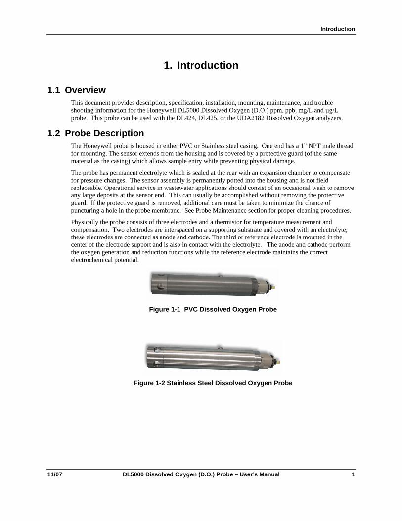
1.2 Probe Description The Honeywell probe is housed in either PVC or Stainless steel casing. One end has a 1” NPT male thread for mounting. The sensor extends from the housing and is covered by a protective guard (of the same material as the casing) which allows sample entry while preventing physical damage.
The probe has permanent electrolyte which is sealed at the rear with an expansion chamber to compensate for pressure changes. The sensor assembly is permanently potted into the housing and is not field replaceable. Operational service in wastewater applications should consist of an occasional wash to remove any large deposits at the sensor end. This can usually be accomplished without removing the protective guard. If the protective guard is removed, additional care must be taken to minimize the chance of puncturing a hole in the probe membrane. See Probe Maintenance section for proper cleaning procedures.
Physically the probe consists of three electrodes and a thermistor for temperature measurement and compensation. Two electrodes are interspaced on a supporting substrate and covered with an electrolyte; these electrodes are connected as anode and cathode. The third or reference electrode is mounted in the center of the electrode support and is also in contact with the electrolyte. The anode and cathode perform the oxygen generation and reduction functions while the reference electrode maintains the correct electrochemical potential.
Figure 1-1 PVC Dissolved Oxygen Probe
Figure 1-2 Stainless Steel Dissolved Oxygen Probe

2 DL500 Dissolved Oxygen (D.O.) Probe – User’s Manual 11/07
1.3 Operating Principal When the probe is placed into the sample stream, oxygen diffuses through the membrane and is reduced at the cathode, and an equal amount of oxygen is generated at the anode. The diffusion continues until the oxygen partial pressure on both sides of the membrane is equal and a balance exists. The electrical circuit is designed such that the current necessary to maintain this equilibrium is converted to read out the dissolved oxygen concentration in the solution.
The reactions are as follows:
At cathode: O2 + 4H+ + 4 e- → 2H2O
At anode: 2H2O → O2 + 4H+ + 4 e-
Result: No net reaction

Specifications
11/07 DL5000 Dissolved Oxygen (D.O.) Probe – User’s Manual 3
2. Specifications Table 2-1 DL5000 Specifications
Parameter Description
Temperature Range 2 – 60°C (35.6 – 140°F)
Storage Temperature: 2 – 60°C (35.6 – 140°F)**
Maximum Pressure PVC Probe: 30 psi (207 kPa) SS Probe: 50 psi (345 kPa)
Maximum Flow Rate No dependence on stirring or flow. However, a minimal flow of 100 ml/min is expected to provide a “flowing” sample. Flow through mounting: 300 ml/min
In-line mounting: 5 gal/min (18.9 L/min)in a 1” Schedule 40 line
Submersion mounting: Not applicable
Response Time 90% in 60 seconds (after probe warm-up)
Probe Accuracy In ppb measurements: ±5% or 2 ppb-μg/L whichever is greater at calibration conditions, after stabilization
In ppm measurements: ±0.2 ppm-μg/L at calibration conditions, after stabilization
Probe Materials of Construction PVC or Stainless Steel
Probe Dimensions (with integral cable) 8.62” L x 1.315” OD (219 x 34 mm)
Probe Weight PVC: 1.24 lb (0.6 kg)
SS: 3.5 lb (1.5 kg)
Approvals SS Probe is manufactured to comply with ASME boiler and pressure vessel code section III, Div. 1, UG-101 CRN #0F11607.5C
This CRN approval only applies to the SS Probe.
**ATTENTION Probe membrane must be kept wetted both in the process and during storage. See Storage under Maintenance section.
The silicone membrane surrounding the D.O. probe is permanent. If this membrane is removed by user for any reason, the warranty on the D.O. probe is voided

Installation
4 DL500 Dissolved Oxygen (D.O.) Probe – User’s Manual 11/07
3. Installation
3.1 Mounting and Wiring with DirectLine
3.1.1 DL424/425 The following section describes the installation of the Honeywell D.O. probe with the DL424/425 Integral Mounting.
Table 3-1 Integral Mounting Procedure
Step Procedure
1 Connect the probe to the process source (using the appropriate mounting from those supplied for the DL5000). Make sure that the final position of the installed electronics module allows the display to be easily viewed by personnel.
2 Apply a thin film of silicon grease on the ID of the electronics module’s probe mounting cavity.
3 Align the slots on the electronics module with those on the probe and press down to connect the electronics to the probe.
4 Tighten the locking screw on the bottom rear of the electronics module.
Step 1
Step 2
Step 3 Step 4
Locking Screw inRear of Housing
ElectronicsModule
Probe
Figure 3-1 Integral Mounting

Installation
11/07 DL5000 Dissolved Oxygen (D.O.) Probe – User’s Manual 5
3.1.2 DL424/425 Remote Mounting When the DL424 or DL425 module is specified for remote mounting, a remote connector assembly (part number 51500768-005) is supplied loose. The remote cable connector is used to connect the DL5000 probe cable to the DL424/425 module. Table 3-2 gives the mounting procedure.
Table 3-2 Remote Mounting and Wiring Procedure for DL5000 Probes
Step Procedure (Refer to Figure 3-2 )
1 Turning counterclockwise, remove strain relief/cover combination from the remote connector assembly.
2 Remove the protective plastic bag from the end of the probe cable. Be careful to keep bare fingers away from coax cable termination.
3 Loosen and remove compression cap from strain relief fitting. Carefully push cable end through cap and strain relief fitting so that these parts are strung back along cable jacket.
4 Connect cable leads as follows: See Figure 3-2.
Terminal 1 = Pigtail Shield Lead (Black/White) Terminal 2 = Temperature Compensation Lead (Orange) Terminal 3 = Temperature Compensation Lead (Yellow) Terminal 4 = Anode (Red) Terminal 5 = Reference (Green) Terminal 6 = Cathode Silver Pin (Coax) Earth Ground = Blue
5 Slide cover along cable and tighten by hand onto the remote connector assembly.
6 Slide cap along cable and tighten onto cable jacket with small wrench until cable cannot slide within strain relief rubber bushing.
7 Remove red protective vinyl boot from opposite end of connector assembly.
8 Apply a thin film of silicon grease to the ID of electronics module’s remote mounting cavity.
9 Plug remote connector assembly into DL424/425 module aligning polarity tab of module housing and mating groove on connector.

Installation
6 DL500 Dissolved Oxygen (D.O.) Probe – User’s Manual 11/07
1
2
3
6
5
4
123456
Pigtail Shield (Black/White)Temperature Compensation (Orange)Temperature Compensation (Yellow)Anode (Red)Reference (Green)Cathode Silver Pin (Coax)Earth Ground (Blue)
CompressionCap
StrainRelief
Cover
ProtectiveVinyl Boot(remove)
1
2
MODE
Remote Electronics forModule DL5000 Dissolved Oxygen Probes
Remote Wiring Cable
Probe
ElectronicsModule
DL5000 Probe Electronics
Figure 3-2 Remote Wiring

Installation
11/07 DL5000 Dissolved Oxygen (D.O.) Probe – User’s Manual 7
3.2 Differences between the Quick Disconnect and Integral Cable options
The cable options of quick disconnect and integral cable do not affect the performance of the DO probe. These options only relate to how the cell is connected to the instrument.
• There are different electrical connections for these options. Refer to Section 3.3 for instructions.
• Integral cable means the cable is potted into the DO probe. The cable and probe are one entity and cannot be separated.
• The quick disconnect option means the DO probe is connected to the cable by a receptacle on top of the probe. The probe and the cable are separate entities. When the time comes to replace the probe, the cable does not have to be replaced. The cable can simply be mated with another DO probe with the quick disconnect option.
3.3 Mounting and Wiring with UDA2182 When connecting the probe to the UDA2182 Analyzer, the probe wiring should always be separated from the AC power wiring. After the analyzer and probe have been securely mounted, the probe should be connected to the analyzer.
3.3.1 Wiring DO Probe with Integral Cable Table 3-3 Wiring DL5000 Probes with Integral Cable to UDA2182
Step Procedure (Refer to Figure 3-3)
1 Remove protective insulator tape from the green lead
2 Loosen screws holding the lock bar and slide the lock bar away from the DO input card
3 Completely withdraw the DO input card from its connection to the backplane motherboard
4 Inset the card back in its guides
5 Slide the card into the point where the lock bar will re-locate into the notch in the DO input card allowing the screw terminals to be accessed for probe wire connection
6 CONNECTING: Connect cable leads as follows (See Figure 3-3)** Wiring must be done in order shown!
Blue Shield wire first, then follow this order: Red Green Coax (clear) Guard (black) Yellow Orange
7 DISCONNECTING: Disconnect cable leads as follows Wiring must be done in order shown!
Orange wire first, then follow this order: Yellow Guard (Black) Coax (Clear) Green Red Blue Shield Wire

Installation
8 DL500 Dissolved Oxygen (D.O.) Probe – User’s Manual 11/07
CAUTION When installing the probe the wiring must be done in the order shown in Table 3-3, even if the analyzer is not powered. This is because the battery backup card is continuously supplying a voltage (bias) to the terminals.
Figure 3-3 Connect/Disconnect Sequence for the DO Probe with an Integral Cable and the
UDA2182

Installation
11/07 DL5000 Dissolved Oxygen (D.O.) Probe – User’s Manual 9
3.3.2 Wiring DO Probe with Quick Disconnect Option Table 3-4 Wiring DL5000 Probes with Quick Disconnect Cable to UDA2182
Step Procedure (Refer to Figure 3-4)
1 Remove protective insulator tape from the green lead
2 Loosen screws holding the lock bar and slide the lock bar away from the DO input card
3 Completely withdraw the DO input card from its connection to the backplane motherboard
4 Inset the card back in its guides
5 Slide the card into the point where the lock bar will re-locate into the notch in the DO input card allowing the screw terminals to be accessed for probe wire connection
6 CONNECTING: Connect cable leads as follows (See Figure 3-4)** Wiring must be done in order shown! Violet Shield wire first, then follow this order: Yellow Orange Coax Guard (Black) Green Red *Ignore blue and brown leads
7 DISCONNECTING: Disconnect cable leads as follows Wiring must be done in order shown! Red wire first, then follow this order: Green Guard (Black) Coax Orange Yellow Violet Shield Wire *Ignore blue and brown leads
CAUTION When installing the probe the wiring must be done in the order shown in Table 3-4, even if the analyzer is not powered. This is because the battery backup card is continuously supplying a voltage (bias) to the terminals.

Installation
10 DL500 Dissolved Oxygen (D.O.) Probe – User’s Manual 11/07
CONNECTING: Violet Shield wire first, then follow this order: Yellow Orange Coax Guard (Black) Green Red *Ignore blue and brown leads
DISCONNECTING: Red wire first, then follow this order: Green Guard (Black) Coax Orange Yellow Violet Shield Wire *Ignore blue and brown leads
Figure 3-4 Connect/Disconnect Sequence for the DO Probe with Quick Disconnect Option and the UDA2182
3.3.3 System Check for Probe with UDA2182 Analyzer Perform a system check upon completion of all wiring. AC noise in the various analyzer output connections may affect the bias amplifier resulting in a DC current in the reference lead. This DC current will cause dissolution on the silver reference electrode over time resulting in a shortened probe life.
See 14.8 Appendix G in the UDA2182 Operator manual for directions on Noise testing.
3.4 Probe System Check When the probe is connected for the first time, replaced or just disconnected and reconnected, a conditioning period of 24 hours is needed before the probe can make an accurate measurement. During this time period, the probe must be kept wetted by either putting it in the process water or in a container of water exposed to air. For ppb - µg/L applications, it is recommended that process conditions are used. Once the 24 hour period has elapsed, the probe can be calibrated. The calibration instructions are as follows:
1. Remove probe from either the process or container of water and put in ambient air. If probe was in process wastewater, clean probe first per cleaning instructions under the maintenance section. If the probe is in a ppb –µg/L process expose the probe to air for 2 - 4 hours before doing an Air calibration.
2. Perform an Air calibration or Sample calibration. Make sure probe temperature is stable before performing an Air calibration. If temperature is not stable, the Air calibration will fail.
Guard
RTH Low
RTH High
Earth Ground
Black
Orange
Green
Wire to chassis ground screw
SignalNameSignalName
Wire ColorWire Color
10 9 8 7 6 5 4 3 2 1
10 9 8 7 6 5 4 3 2 1
RTH Low
RTH High
Coax 10 9 8 7 6 5 4 3 2 1
10 9 8 7 6 5 4 3 2 1
RTH Low
RTH High
Yellow
Red
Cable shield (Violet) to chassis ground screw Cathode
Reference
Anode

Installation
11/07 DL5000 Dissolved Oxygen (D.O.) Probe – User’s Manual 11
ATTENTION Do not perform an Air calibration on a windy day or during freezing temperatures. The temperature will not stabilize on a windy day and freezing temperatures will cause the probe’s electrolyte to freeze and the membrane to crack.
3. At completion of a successful air or sample calibration, put probe into process water.
After the initial calibration, the probe should only be removed from the process for periodic cleaning and calibration. The recommended cleaning schedule for ppb applications is monthly and for ppm – mg/L applications it is bi-monthly. If the probe’s response has slowed or readings are lower than expected prior to the recommended cleaning schedule, the probe may need to be cleaned more frequently. The recommended calibration schedule for ppb – µg/L, and ppm - mg/L applications is monthly. If individual plant maintenance schedules require it, the probe may be calibrated more frequently.

Installation
12 DL500 Dissolved Oxygen (D.O.) Probe – User’s Manual 11/07
3.5 Probe Mountings
3.5.1 Inline flow mounting In applications where the probe goes directly into the process pipeline, the in-line flow mounting is available. This mounting is diagramed in Figure 3-5.
30669860-017 O-ring
Customer Installation
3/4” NPT (REF)
Kit #51452226-001 (SST)51452226-002 (PVC)
Figure 3-5 In-Line Mounting Kit
3.5.2 Flow - Through Mounting
In most low ppb- µg/L applications, the Pure Water Flow -Through mounting is recommended. This assembly is usually pipe clamp mounted close to the sampling port. A single 1” pipe clamp is normally all that is needed for physical mounting. Inlet and outlet fittings are designed to mate to ¼” O.D. tubing.
ATTENTION When assembling the flow through kit, extreme caution must be used when installing or removing the probe flow assembly from the probe. The assembly threads can cut the membrane if they contact it (especially the stainless steel assemblies).
In ppb - µg/L applications, the integrity of the sample lines feeding the ppb probe is of extreme importance. Since the oxygen level in air is usually three orders of magnitude greater than the sample level, oxygen can leak into the sample lines without any indication of liquid leaking out, resulting in erroneous readings. To reduce risk of leaks, use a minimum number of fittings in the sample lines and make sure each fitting is tightened.
The sample should be discharged to Atmospheric pressure (open drain).
Installation
11/07 DL5000 Dissolved Oxygen (D.O.) Probe – User’s Manual 13
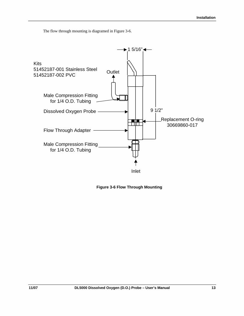
The flow through mounting is diagramed in Figure 3-6.
Kits51452187-001 Stainless Steel51452187-002 PVC
Male Compression Fittingfor 1/4 O.D. Tubing
Dissolved Oxygen Probe
Flow Through Adapter
Male Compression Fittingfor 1/4 O.D. Tubing
Inlet
9 1/2”
Replacement O-ring30669860-017
Outlet
1 5/16”
Figure 3-6 Flow Through Mounting

Installation
14 DL500 Dissolved Oxygen (D.O.) Probe – User’s Manual 11/07
3.5.3 Mounting Recommendation for Easy Calibration in Boiler Control Loop
A "Trap" arrangement should be plumbed in the incoming flow to the DO probe so that if flow is shut off or an "Upstream" pipe opened, water will remain around the tip of the probe. Keeping it moist on the outlet side, an arrangement such as a "TEE" should be made to assure that when the 3-way valve is opened (for Air Calibration), the water within the probe flows out. "Cracking" the fittings on the inlet side will achieve the same result as a 3-way valve, but repeated "Cracking" will cause wear on the parts and any additional handling may shorten the life of the probe.
AIR
DRAIN
DRAIN
PROBE
FLOWMETER
TRAP
3-WAYVALVE
FLOW
TEMP
PRESS
X
Figure 3-7 Mounting Recommendation for Easy Calibration in Boiler Control Loop
To avoid drying out the probe sensor when the sampling point is shut off, a water trap should be made in the inlet piping

Maintenance
11/07 DL5000 Dissolved Oxygen (D.O.) Probe – User’s Manual 15
4. Maintenance
4.1 Introduction The Honeywell D. O. probe requires no internal probe maintenance. However, like all other probes, it does need to be cleaned periodically. After a long period of use, the oxygen transfer may cease due to a coating buildup. This buildup may consume or block the oxygen, increase the response time and / or reduce the probe accuracy. Cleaning the probe is easy and is normally accomplished by agitating the probe in a container of fluid. The cleaning fluid can vary from water to a 10% HCl solution depending on the type of buildup or fouling encountered.
Inert Fouling (For example, hair, grease, and solids) This type of fouling normally occurs in wastewater applications; however, rust-like contaminants may occur in ppb-µg/L applications. When a significant amount of this debris is deposited on the probe, the response time of the probe slows down. Normal cleaning practices should restore probe to correct operation.
Biologically Active Slime This type of fouling consists of biologically active slime adhering either loosely or tightly to the probe or the protective cap or both. This slime can be visible or invisible and may produce a sticky feel to the probe and / or cap’s surface area. This type of fouling is usually characterized by the following performance: the signal drifts slowly downward for several hours (or days) and then drops precipitously toward zero in a matter of a few hours or less. Proper air calibration can be restored only after very careful wiping of the probe tip or a 30 second rinse in a 10% HCl solution. The time between cleanings can be extended by relocating the probe to a cleaner environment (nearer the effluent) or relocating the probe to where the water is flowing faster. After these actions are taken, a cleaning schedule should be established.
ATTENTION Never use a brush to clean a Honeywell D.O. probe as it can cause a tear in the probe membrane rendering it inoperable. This type of abuse is not covered under probe warranty.
4.2 To Clean Cleaning should consist of the simplest of the following required to re-establish proper performance: 1.) Rinse with water 2.) Rinse with mild detergent followed by water 3.) Rinse with 10% HCl followed by mild detergent followed by water. If the probe must be wiped, carefully use a paper towel or cotton swab. After cleaning is completed, place the probe back into the process and allow 60 minutes before a calibration.
4.3 O-Ring Replacement To replace the O-ring shown in Figure 3-6:
1. Place the O-ring over the threads of either the flow through or in-line fitting.
2. Silicone grease may be used to assist in O-ring installation.
3. Attach the adapter to the probe. Be careful not to touch the probe membrane.

Maintenance
16 DL500 Dissolved Oxygen (D.O.) Probe – User’s Manual 11/07
4.4 Probe Storage
Short term The Honeywell probe arrives from the factory with a red cap on the end of the probe. This cap contains a 3% solution of Isopropyl alcohol and water. The water keeps the probe wetted until it is put into the process. The alcohol minimizes the growth of bacteria.
Long term If the probe remains on the shelf for longer than 6 months, the solution inside the cap must be replaced. To do this, remove the side mounted, threaded pipe plug using a 3/16 hex key wrench. Fill the hole with a fresh solution of 3% Isopropyl alcohol and water, and replace the hex screw. This procedure keeps the probe wetted and minimizes incidence of bacteria.
4.5 Packing Probe for Shipment or Storage When removing the probe from service for storage or shipment, replace the red cap that came with the probe. Fill the probe as described in Storage – Long term. This prevents damage caused by long-term contact with the other probe leads.

Troubleshooting
11/07 DL5000 Dissolved Oxygen (D.O.) Probe – User’s Manual 17
5. Troubleshooting
5.1 Diagnostic Error Messages DL424/425 When a diagnostic error or status condition occurs, the Online Display alternates between measured DO and a text message.
Table 5-1 Online Diagnostic Errors
What you see What it is What to do
CnFG Configuration or Calibration data is defective. Reset unit or cycle power.
Second occurrence will show FALt.
FALt Unit electronics are defective. Replace electronics module.
These errors may occur when on-line DO Concentration or on-line Temperature is displayed.
dOHI Measured DO is > 20 ppm/200 ppb Bring process to within limits
dOLo Measured DO is < 0.00 ppm/ppb Bring process to within limits
PrbE Probe is defective, wrong type, or not connected.
Probe current is excessive with probe voltage near 0 volts.
Forces the output to burnout level (greater than 22 mA).
Check for an electrical short between the anode and the cathode.
Check the reference electrode connection.
When the source of the error is removed, the error will clear and the output will return to normal operation.
T HI Measured temperature is > 60 °C Bring process to within limits
T LO Measured temperature is < 2.0 °C Bring process to within limits
bErr Probe Bias Error: Probe current has exceeded expected probe current by 33% for at least 20 seconds.
If the excessive current condition continues after a manual probe bias , the PrbE error is generated. If excessive current is not present then the bErr remains.
Application related shift in probe bias voltage
Remove the probe from process and do a probe bias calibration. In ppm applications in processes containing CO2, the probe may be left in the process and the Bias can be manually adjusted.
Remove the probe from the process and do an Air Calibration
Troubleshooting
18 DL500 Dissolved Oxygen (D.O.) Probe – User’s Manual 11/07
What you see What it is What to do
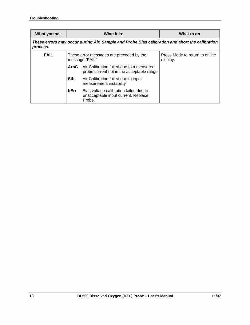
These errors may occur during Air, Sample and Probe Bias calibration and abort the calibration process.
FAIL These error messages are preceded by the message “FAIL”
ArnG Air Calibration failed due to a measured probe current not in the acceptable range
Stbl Air Calibration failed due to input measurement instability
bErr Bias voltage calibration failed due to unacceptable input current. Replace Probe.
Press Mode to return to online display.

Troubleshooting
11/07 DL5000 Dissolved Oxygen (D.O.) Probe – User’s Manual 19
5.2 Troubleshooting UDA2182 Analyzer The Honeywell UDA2`182 Operator manual contains many tips for trouble shooting the UDA2182 analyzer. Consult the DO Probe and Analyzer Tests section of the Manual 14.9 Appendix H for a comprehensive range of checks.
In addition, the appendix section of the Honeywell UDA2182 Operator manual provides information on various subjects related to the D.O. probe, including the following topics:
• Excess AC noise can result in a shorten probe life. To ensure that there is no excess noise on the probe leads, use the procedure in 14.8 Appendix G in the UDA2182 Operator manual – Noise Testing to test your probe installation.
• If a D.O. reading doesn’t seem correct, check that the probe and analyzer are working correctly by using the procedures provided in 14.9 Appendix H in the UDA2182 manual – Probe and Analyzer Tests.
• To confirm the D.O. measurement in air at a specific temperature, consult 14.12 Appendix K in the UDA2182 manual – Percent Saturation Readout to get the expected DO concentration in air or air saturated water at various temperatures. This information will confirm if the probe is giving a valid measurement in air.
• If a leak is suspected in a ppb system, consult 14.13 Appendix L in the UDA2182 manual – Leak Detection in PPB Applications to understand how to use the D.O. probe to find a leak.
• Want proof that a D.O. probe can go down to zero ppb’s? Consult 14.14 Appendix M in the UDA2182 manual – Procedure for Low level ppb Dissolved Oxygen testing to confirm that your probe can get down to zero ppb’s.
5.3 Processes Containing Carbon Dioxide When measuring D.O. in a process containing carbon dioxide (e.g. beer or soda) special procedures are required to protect the probe. To remove the probe from the line:
1. Shut off sample line containing CO2.
2. Purge the line containing the probe with fresh water at the same pressure for 15 minutes to remove the CO2 from the D. O. probe.
3. Remove probe when convenient.
CAUTION Not following this procedure will cause internal rupture of the membrane rendering the probe inoperable, un-repairable and void of any probe warranty. For optimum performance in this application, the bias voltage should be adjusted to measure 450 mV instead 600 mV. Review the UDA2182 operator manuals for adjusting the Probe Bias.
Troubleshooting
20 DL500 Dissolved Oxygen (D.O.) Probe – User’s Manual 11/07
5.4 Leak Detection in PPB- μg/L Applications Before performing and air leak detection, it is necessary to determine that both the probe and analyzer are working properly.
First, check to see that the probe contains an O-ring. Per the probe directions, an O-ring must go into a probe that is used in ppb applications. This creates a tight seal between the probe and flow chamber.
MAKE SURE THIS O-RING IS IN THE PROBE.
1. Unless already in air, open the probe to air for 30 seconds.
2. Put it back into the process again.
3. Allow the DO to drift down to the 20-30 ppb-µg/L range. The 20-30 ppb-µg/L range was chosen because the reading was low enough that the drift was small with respect to the changes observed for various flow rates but high enough that changes could be observed.
4. At this range, vary the flow rate from 10 to 100 ml/min. These low flow rates were selected for two reasons. The first, the tester many only have a 0 - 100 ml/min flow indicator. The other reason, is a leak that exists at this low flow, will cause a change in the DO reading.
5. If the DO value at 10 ml/min exceeds the DO value at 100 ml/min, a leak is present in the sampling line.
6. Fixing the leak may require plastic tubing to be replaced with metal tubing, tape to be put on fittings, and/or fittings at the bottom of the probe to be tightened securely.
7. Now, repeat Steps 2 - 6 until the flow can be changed from >100 ml/min to 10 ml/min with no change in the DO value.
Troubleshooting
11/07 DL5000 Dissolved Oxygen (D.O.) Probe – User’s Manual 21

Honeywell Process Solutions
512 Virginia Drive
Fort Washington, PA 19034
70-82-25-114 1107 Printed in USA http://hpsweb.honeywell.com