Embed Size (px)
DESCRIPTION
Dlro60
Citation preview
M
DLRO® 600High Current, Low Resistance Ohmmeter
USER MANUAL
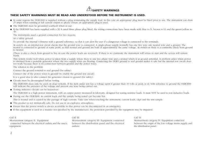
GSAFETY WARNINGS
THESE SAFETY WARNINGS MUST BE READ AND UNDERSTOOD BEFORE THE INSTRUMENT IS USED.
n In some regions the DLRO600 is supplied without a plug terminating the supply lead. In this case an appropriate plug must be fitted prior to use. The instrument can draw 25 amps when running at full current output so please ensure an appropriate plug is used.
n The DLRO600 must be grounded (earthed) when in use.
n If the DLRO600 has been supplied with a 32 A rated three phase plug fitted, the wiring connections have been made with blue to N, brown to L1 and the green/yellow to g.
The instruments need a ground connection for two reasons.
As a safety ground.
To provide the internal voltmeter with a ground reference, so that it can alert the user if a dangerous voltage is connected to the terminals.
At switch on, an internal test circuit checks that the ground wire is connected. A single-phase supply normally has one live wire one neutral wire and a ground. The neutral is connected to ground at some point, so that neutral and ground are both at approximately the same voltage. At switch-on there is a continuity check from ground to neutral.
(There is also a check from ground to live in case the power leads are reversed). If there is no continuity the instrument will refuse to start and the screen will remain blank.
This system works well when power is taken from a supply where there is one live phase wire and a neutral which is at ground potential. A problem arises when power is obtained from a portable generator where the two supply wires are floating. Connecting the DLRO ground to real ground makes it safe but the internal test circuit does not work because there is no connection between ground and the power wires.
The solution to the problem:
Connect the ground terminal to real ground (for safety).
Connect one of the power wires to ground (to enable the ground test circuit).
It is a good idea to also connect the generator chassis to ground (for safety).
n Circuits must be de-energised before testing.
The DLRO600 must only be used on dead systems. If the item under test has a voltage upon it greater than 10 volts ac peak or dc with reference to ground the DLRO600 will indicate the presence of the voltage and prevent any tests being carried out.
n Testing inductive circuits can be hazardous:
The DLRO600 is a high power instrument, with an output power measured in kilowatts, designed for testing resistive loads. It must NOT be used to test inductive loads.
n During use the DLRO600, its current leads and the sample being tested can become hot.
This is normal and is caused by the passage of high currents. Take care when touching the instrument, current leads, clips and the test sample.
n This product is not intrinsically safe. Do not use in an explosive atmosphere.
n Ensure that the power switch is always accessible so that power can be disconnected in an emergency.
n If this equipment is used in a manner not specified by the manufacturer, the protection provided by the equipment may be impaired.
2
CAT IIMeasurement category II: Equipment connected between the electrical outlets and the user’s equipment.
CAT IIIMeasurement category III: Equipment connected between the distribution panel and the electrical outlets.
CAT IV Measurement category IV: Equipment connected between the origin of the low-voltage mains supply and the distribution panel.
SYMBOLS USED IN THIS DOCUMENT AND ON THE INSTRUMENT
u Protective conductor terminal
s Hot terminals
G Refer to the User Manual for more information
1 Power On
0 Power Off
c Equipment complies with relevant EU Directives
Do not dispose of in the normal waste stream
CONTENTS
3
SAFETY WARNINGS 2
GENERAL DESCRIPTION 4
OPERATION 5
Main menu screen 5
TEST menu 6
OPTIONS menu 7
CURRENT menu 9
Warning messages 9
Entering notes in the memo screen 9
Test result storage 10
Real time downloading of test data. 10
TEST TECHNIQUES & APPLICATIONS 11
Test sequence 11
Lead resistance 11
Interference and grounding the sample 11
SPECIFICATIONS 12
Repair and Warranty 13
End of life disposal 13
The use of a four terminal measurement technique removes the test lead resistance from the measured value although the use of lightweight current leads may prevent the DLRO600 from producing the full requested current. In this case the instrument will produce the highest current possible taking into account the resistance of the current leads and the item being tested.
Before a test may be started the potential test lead contact is monitored to ensure good contact is present. This reduces the chance of erroneous readings and prevents arcing at the contact point, which would otherwise damage the item under test and the test lead contacts. A resistance measurement takes approximately 7 seconds.
DLRO600 is supplied complete with a pair of 5 metre (16 feet) current leads terminated with large clamps, and smaller, lighter potential leads. Other lengths and terminations are available if required.
The DLRO600 will operate with a supply voltage from 100 to 265 volts but it will only work to full specification from 207 to 265 volts. If the input voltage is less than 207 volts it may not be possible to obtain an output of 600 amps. When the supply is at its lower limit of 100 volts, an output current of at least 200 amps will be possible when using the standard leads (connected to C1 and C2 terminals). If the supply voltage is low, higher output currents can be obtained by using thicker or shorter current leads.
The large terminals C1 and C2 supply a low voltage (from zero to 5 volts) which is adjusted automatically to produce the desired current (from 10 A to 600 A). C1 is the positive terminal. This d.c. voltage is half wave rectified and unsmoothed, the inductance of the test leads providing sufficient smoothing for the current.
P1 and P2 are voltage measuring terminals. P1 is nominally positive, but connections can be reversed without affecting the measurement. All four terminals are floating.
A warning will be given if dangerous voltages are connected to any terminal (C or P) with respect to ground.
GENERAL DESCRIPTION
4
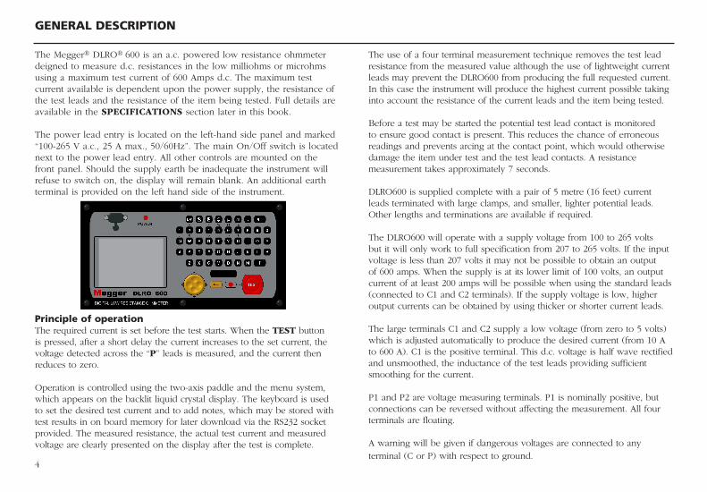
The Megger® DLRO® 600 is an a.c. powered low resistance ohmmeter deigned to measure d.c. resistances in the low milliohms or microhms using a maximum test current of 600 Amps d.c. The maximum test current available is dependent upon the power supply, the resistance of the test leads and the resistance of the item being tested. Full details are available in the SPECIFICATIONS section later in this book.
The power lead entry is located on the left-hand side panel and marked “100-265 V a.c., 25 A max., 50/60Hz”. The main On/Off switch is located next to the power lead entry. All other controls are mounted on the front panel. Should the supply earth be inadequate the instrument will refuse to switch on, the display will remain blank. An additional earth terminal is provided on the left hand side of the instrument.
Principle of operationThe required current is set before the test starts. When the TEST button is pressed, after a short delay the current increases to the set current, the voltage detected across the “P” leads is measured, and the current then reduces to zero.
Operation is controlled using the two-axis paddle and the menu system, which appears on the backlit liquid crystal display. The keyboard is used to set the desired test current and to add notes, which may be stored with test results in on board memory for later download via the RS232 socket provided. The measured resistance, the actual test current and measured voltage are clearly presented on the display after the test is complete.
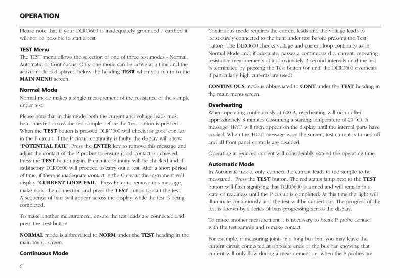
After a slight pause the display will change to the Main Menu screen.
MAIN MENU SCREENThis screen provides access to the menuing system, through which you set
up your instrument and choose the desired test parameters. Navigation of
this menuing system is by means of the cursor control and Enter key.
At the top of the screen are the three main menu choices; “TEST”,
“OPTIONS” and “CURRENT”.
Below this are details of the test current selected (SET CURRENT),
maximum current to be allowed (CURRENT LIMIT), the number of stored
tests and the current date and time.
To perform a measurement is straightforward.
1. Use the Left and Right arrows of the two-axis cursor control to
highlight the TEST menu. Use the down arrow to select the
required test type. Press Enter.
2. Use the Left and Right arrows of the two-axis cursor control to
highlight the CURRENT menu. Use the down arrow to select SET
and press Enter. Type in the desired current using the numeric keys
on the keypad. When finished press Enter.
If the current you have set is greater than the current limit, DLRO600
will beep and clear the SET CURRENT field. Re-enter the desired
current, if necessary increasing the current limit to a value equal to
or greater than the desired level. (See separate topic for setting the
current limit).
3. Connect the sample to be tested to the instrument terminals and
press the TEST button. The different test types have slightly
different connection requirements, which are detailed, in the
sections below.
OPERATION
5
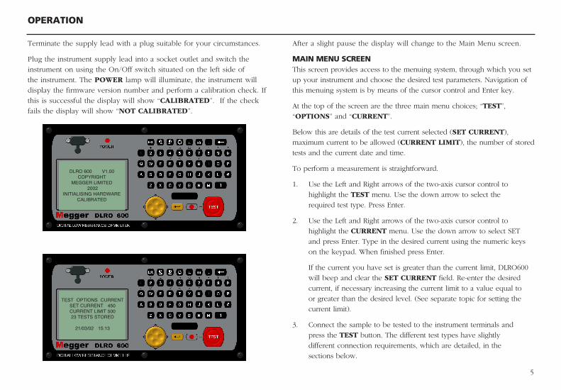
Terminate the supply lead with a plug suitable for your circumstances.
Plug the instrument supply lead into a socket outlet and switch the
instrument on using the On/Off switch situated on the left side of
the instrument. The POWER lamp will illuminate, the instrument will
display the firmware version number and perform a calibration check. If
this is successful the display will show “CALIBRATED”. If the check
fails the display will show “NOT CALIBRATED”.
DLRO 600 V1.00COPYRIGHT
MEGGER LIMITED 2002
INITIALISING HARDWARECALIBRATED
TEST OPTIONS CURRENTSET CURRENT 450 CURRENT LIMIT 500 23 TESTS STORED
21/03/02 15:13
6
OPERATION
Please note that if your DLRO600 is inadequately grounded / earthed it
will not be possible to start a test.
TEST MenuThe TEST menu allows the selection of one of three test modes - Normal,
Automatic or Continuous. Only one mode can be active at a time and the
active mode is displayed below the heading TEST when you return to the
MAIN MENU screen.
Normal ModeNormal mode makes a single measurement of the resistance of the sample
under test.
Please note that in this mode both the current and voltage leads must
be connected across the test sample before the Test button is pressed.
When the TEST button is pressed DLRO600 will check for good contact
in the P circuit. If the P circuit continuity is faulty the display will show
“POTENTIAL FAIL”. Press the ENTER key to remove this message and
adjust the contact of the P probes to ensure good contact is achieved.
Press the TEST button again. P circuit continuity will be checked and if
satisfactory DLRO600 will proceed to carry out a test. After a short period
of time, if there is inadequate contact in the C circuit the instrument will
display “CURRENT LOOP FAIL”. Press Enter to remove this message,
make good the connection and press the TEST button to start the test.
A sequence of bars will appear across the display while the test is being
completed.
To make another measurement, ensure the test leads are connected and
press the Test button.
NORMAL mode is abbreviated to NORM under the TEST heading in the
main menu screen.
Continuous Mode
Continuous mode requires the current leads and the voltage leads to
be securely connected to the item under test before pressing the Test
button. The DLRO600 checks voltage and current loop continuity as in
Normal Mode and, if adequate, passes a continuous d.c. current, repeating
resistance measurements at approximately 2-second intervals until the test
is terminated by pressing the Test button (or until the DLRO600 overheats
if particularly high currents are used).
CONTINUOUS mode is abbreviated to CONT under the TEST heading in
the main menu screen.
OverheatingWhen operating continuously at 600 A, overheating will occur after
approximately 3 minutes (assuming a starting temperature of 20 ºC). A
message ‘HOT’ will then appear on the display until the internal parts have
cooled. When the ‘HOT’ message is on the screen, test current is turned off
and all front panel controls are disabled.
Operating at reduced current will considerably extend the operating time.
Automatic ModeIn Automatic mode, only connect the current leads to the sample to be
measured. Press the TEST button. The red status lamp next to the TEST
button will flash signifying that DLRO600 is armed and will remain in a
state of readiness until the P circuit is completed. At this time the light will
illuminate continuously and the test will be carried out. The progress of the
test is shown by a series of bars progressing across the display.
To make another measurement it is necessary to break P probe contact
with the test sample and remake contact.
For example, if measuring joints in a long bus bar, you may leave the
current circuit connected at opposite ends of the bus bar knowing that
current will only flow during a measurement i.e. when the P probes are
OPERATION
7
OPERATION
downloading and formats the data, is also supplied. If using another
package please note the settings should be 9600 baud, 8 data bits, 1
stop bit, and no parity.
Downloading data does not cause the stored data to be erased from
memory. To clear data from memory see “Delete Data” below.
Please note – DLRO600 also makes data available via the RS232
Port in real time and is suitable for printing on a self-powered serial
printer. (See later for details.)
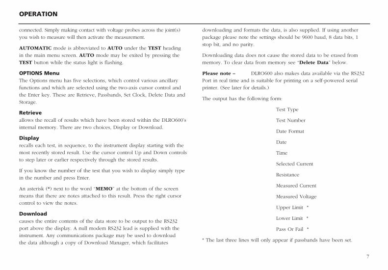
The output has the following form:
Test Type
Test Number
Date Format
Date
Time
Selected Current
Resistance
Measured Current
Measured Voltage
Upper Limit *
Lower Limit *
Pass Or Fail *
* The last three lines will only appear if passbands have been set.
connected. Simply making contact with voltage probes across the joint(s)
you wish to measure will then activate the measurement.
AUTOMATIC mode is abbreviated to AUTO under the TEST heading
in the main menu screen. AUTO mode may be exited by pressing the
TEST button while the status light is flashing.
OPTIONS MenuThe Options menu has five selections, which control various ancillary
functions and which are selected using the two-axis cursor control and
the Enter key. These are Retrieve, Passbands, Set Clock, Delete Data and
Storage.
Retrieveallows the recall of results which have been stored within the DLRO600’s
internal memory. There are two choices, Display or Download.
Displayrecalls each test, in sequence, to the instrument display starting with the
most recently stored result. Use the cursor control Up and Down controls
to step later or earlier respectively through the stored results.
If you know the number of the test that you wish to display simply type
in the number and press Enter.
An asterisk (*) next to the word “MEMO” at the bottom of the screen
means that there are notes attached to this result. Press the right cursor
control to view the notes.
Downloadcauses the entire contents of the data store to be output to the RS232
port above the display. A null modem RS232 lead is supplied with the
instrument. Any communications package may be used to download
the data although a copy of Download Manager, which facilitates
OPERATION
8
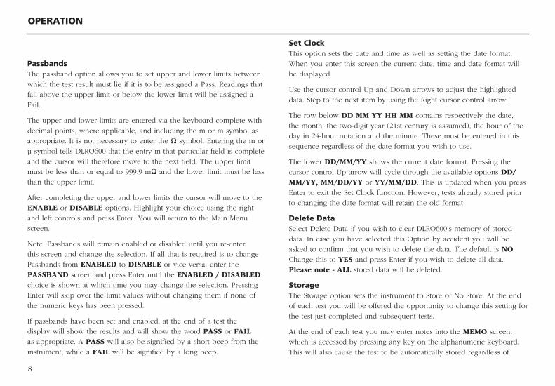
Set ClockThis option sets the date and time as well as setting the date format.
When you enter this screen the current date, time and date format will
be displayed.
Use the cursor control Up and Down arrows to adjust the highlighted
data. Step to the next item by using the Right cursor control arrow.
The row below DD MM YY HH MM contains respectively the date,
the month, the two-digit year (21st century is assumed), the hour of the
day in 24-hour notation and the minute. These must be entered in this
sequence regardless of the date format you wish to use.
The lower DD/MM/YY shows the current date format. Pressing the
cursor control Up arrow will cycle through the available options DD/MM/YY, MM/DD/YY or YY/MM/DD. This is updated when you press
Enter to exit the Set Clock function. However, tests already stored prior
to changing the date format will retain the old format.
Delete DataSelect Delete Data if you wish to clear DLRO600’s memory of stored
data. In case you have selected this Option by accident you will be
asked to confirm that you wish to delete the data. The default is NO.
Change this to YES and press Enter if you wish to delete all data.
Please note - ALL stored data will be deleted.
StorageThe Storage option sets the instrument to Store or No Store. At the end
of each test you will be offered the opportunity to change this setting for
the test just completed and subsequent tests.
At the end of each test you may enter notes into the MEMO screen,
which is accessed by pressing any key on the alphanumeric keyboard.
This will also cause the test to be automatically stored regardless of
PassbandsThe passband option allows you to set upper and lower limits between
which the test result must lie if it is to be assigned a Pass. Readings that
fall above the upper limit or below the lower limit will be assigned a
Fail.
The upper and lower limits are entered via the keyboard complete with
decimal points, where applicable, and including the m or m symbol as
appropriate. It is not necessary to enter the Ω symbol. Entering the m or
µ symbol tells DLRO600 that the entry in that particular field is complete
and the cursor will therefore move to the next field. The upper limit
must be less than or equal to 999.9 mΩ and the lower limit must be less
than the upper limit.
After completing the upper and lower limits the cursor will move to the
ENABLE or DISABLE options. Highlight your choice using the right
and left controls and press Enter. You will return to the Main Menu
screen.
Note: Passbands will remain enabled or disabled until you re-enter
this screen and change the selection. If all that is required is to change
Passbands from ENABLED to DISABLE or vice versa, enter the
PASSBAND screen and press Enter until the ENABLED / DISABLED
choice is shown at which time you may change the selection. Pressing
Enter will skip over the limit values without changing them if none of
the numeric keys has been pressed.
If passbands have been set and enabled, at the end of a test the
display will show the results and will show the word PASS or FAIL
as appropriate. A PASS will also be signified by a short beep from the
instrument, while a FAIL will be signified by a long beep.
OPERATION
9
other settings.
If all memory has been filled, a message MEMORY FULL will appear
and no more tests results will be stored although testing may continue
without storing results. The main menu screen will also display “300 MEMORY FULL” instead of the number of stored tests.
Data is stored for up to 10 years in battery backed RAM.
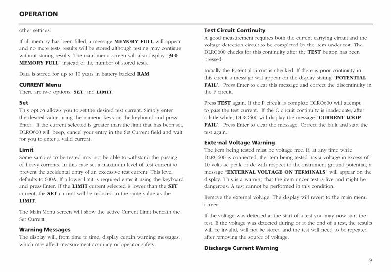
CURRENT MenuThere are two options, SET, and LIMIT.
SetThis option allows you to set the desired test current. Simply enter
the desired value using the numeric keys on the keyboard and press
Enter. If the current selected is greater than the limit that has been set,
DLRO600 will beep, cancel your entry in the Set Current field and wait
for you to enter a valid current.
LimitSome samples to be tested may not be able to withstand the passing
of heavy currents. In this case set a maximum level of test current to
prevent the accidental entry of an excessive test current. This level
defaults to 600A. If a lower limit is required enter it using the keyboard
and press Enter. If the LIMIT current selected is lower than the SET
current, the SET current will be reduced to the same value as the
LIMIT.
The Main Menu screen will show the active Current Limit beneath the
Set Current.
Warning MessagesThe display will, from time to time, display certain warning messages,
which may affect measurement accuracy or operator safety.
Test Circuit ContinuityA good measurement requires both the current carrying circuit and the
voltage detection circuit to be completed by the item under test. The
DLRO600 checks for this continuity after the TEST button has been
pressed.
Initially the Potential circuit is checked. If there is poor continuity in
this circuit a message will appear on the display stating “POTENTIAL FAIL”. Press Enter to clear this message and correct the discontinuity in
the P circuit.
Press TEST again. If the P circuit is complete DLRO600 will attempt
to pass the test current. If the C circuit continuity is inadequate, after
a little while, DLRO600 will display the message “CURRENT LOOP FAIL”. Press Enter to clear the message. Correct the fault and start the
test again.
External Voltage WarningThe item being tested must be voltage free. If, at any time while
DLRO600 is connected, the item being tested has a voltage in excess of
10 volts ac peak or dc with respect to the instrument ground potential, a
message “EXTERNAL VOLTAGE ON TERMINALS” will appear on the
display. This is a warning that the item under test is live and might be
dangerous. A test cannot be performed in this condition.
Remove the external voltage. The display will revert to the main menu
screen.
If the voltage was detected at the start of a test you may now start the
test. If the voltage was detected during or at the end of a test, the results
will be invalid, will not be stored and the test will need to be repeated
after removing the source of voltage.
Discharge Current Warning
OPERATION
10
A message CURRENT FLOW will appear if a current greater than
approximately 10 mA is still flowing after a test is completed. This
suggests that an inductive load has been accidentally tested and is
still discharging. Do not disconnect the current loop while the discharge
warning is showing.
ENTERING NOTES IN THE MEMO SCREENAt the end of each test you may add comments to the test results. Instead
of pressing Enter to return to the Main Menu screen, briefly press any
alphanumeric key. You will enter a MEMO screen that allows you to enter
up to 160 characters of alphanumeric information concerning the test.
When you have entered all information press Enter and the measurement
and memo will be stored in memory.
If you do not wish to add notes press the Test button and a new test will
be started, or the Enter button to return to the Main Screen.
TEST RESULT STORAGEEach test is numbered sequentially, dated and timed. The test result
memory can store a maximum of 300 tests, each being identified by its
test number, date and time. When memory is full the message “MEMORY FULL” will be shown. Testing may continue but no more results will be
stored. See Options Menu – Storage for more information.
REAL TIME DOWNLOADING OF TEST DATA.DLRO600 will output data to the RS232 port every second. The data
is in ASCII format at 9600 baud, 8 bits with 1 stop bit. Connecting an
appropriately configured PC to the RS232 port will enable data to be
captured in real time.
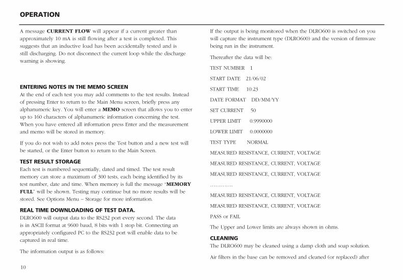
The information output is as follows:
If the output is being monitored when the DLRO600 is switched on you
will capture the instrument type (DLRO600) and the version of firmware
being run in the instrument.
Thereafter the data will be:
TEST NUMBER 1
START DATE 21/06/02
START TIME 10:23
DATE FORMAT DD/MM/YY
SET CURRENT 50
UPPER LIMIT 0.9990000
LOWER LIMIT 0.0000000
TEST TYPE NORMAL
MEASURED RESISTANCE, CURRENT, VOLTAGE
MEASURED RESISTANCE, CURRENT, VOLTAGE
MEASURED RESISTANCE, CURRENT, VOLTAGE
………….
MEASURED RESISTANCE, CURRENT, VOLTAGE
MEASURED RESISTANCE, CURRENT, VOLTAGE
PASS or FAIL
The Upper and Lower limits are always shown in ohms.
CLEANINGThe DLRO600 may be cleaned using a damp cloth and soap solution.
Air filters in the base can be removed and cleaned (or replaced) after
TEST TECHNIQUES & APPLICATIONS
11
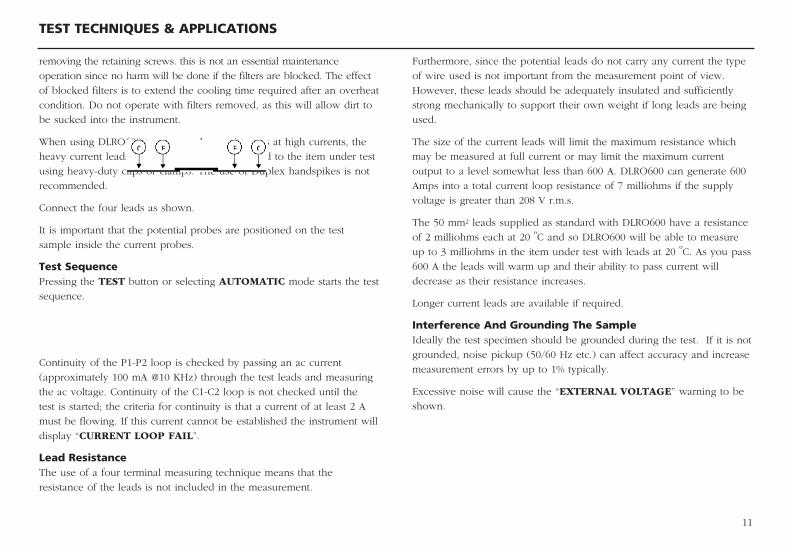
removing the retaining screws. this is not an essential maintenance
operation since no harm will be done if the filters are blocked. The effect
of blocked filters is to extend the cooling time required after an overheat
condition. Do not operate with filters removed, as this will allow dirt to
be sucked into the instrument.
When using DLRO600 to measure low resistances at high currents, the
heavy current leads should be securely connected to the item under test
using heavy-duty clips or clamps. The use of Duplex handspikes is not
recommended.
Connect the four leads as shown.
It is important that the potential probes are positioned on the test
sample inside the current probes.
Test SequencePressing the TEST button or selecting AUTOMATIC mode starts the test
sequence.
Continuity of the P1-P2 loop is checked by passing an ac current
(approximately 100 mA @10 KHz) through the test leads and measuring
the ac voltage. Continuity of the C1-C2 loop is not checked until the
test is started; the criteria for continuity is that a current of at least 2 A
must be flowing. If this current cannot be established the instrument will
display “CURRENT LOOP FAIL”.
Lead ResistanceThe use of a four terminal measuring technique means that the
resistance of the leads is not included in the measurement.
Furthermore, since the potential leads do not carry any current the type
of wire used is not important from the measurement point of view.
However, these leads should be adequately insulated and sufficiently
strong mechanically to support their own weight if long leads are being
used.
The size of the current leads will limit the maximum resistance which
may be measured at full current or may limit the maximum current
output to a level somewhat less than 600 A. DLRO600 can generate 600
Amps into a total current loop resistance of 7 milliohms if the supply
voltage is greater than 208 V r.m.s.
The 50 mm2 leads supplied as standard with DLRO600 have a resistance
of 2 milliohms each at 20 ºC and so DLRO600 will be able to measure
up to 3 milliohms in the item under test with leads at 20 ºC. As you pass
600 A the leads will warm up and their ability to pass current will
decrease as their resistance increases.
Longer current leads are available if required.
Interference And Grounding The SampleIdeally the test specimen should be grounded during the test. If it is not
grounded, noise pickup (50/60 Hz etc.) can affect accuracy and increase
measurement errors by up to 1% typically.
Excessive noise will cause the “EXTERNAL VOLTAGE” warning to be
shown.
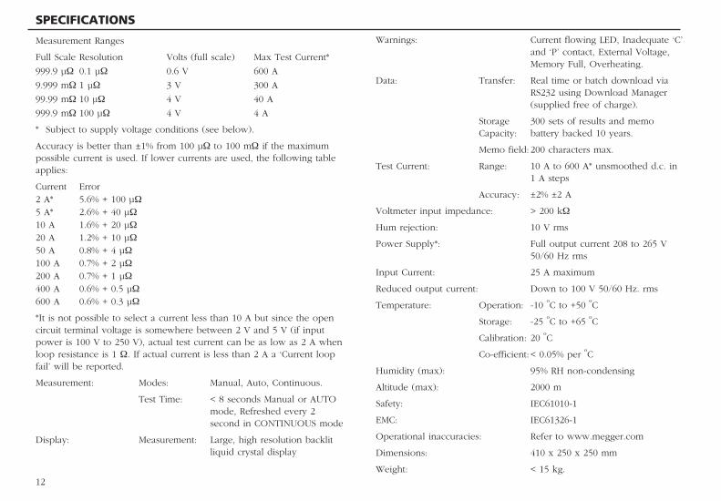
Warnings: Current flowing LED, Inadequate ‘C’ and ‘P’ contact, External Voltage, Memory Full, Overheating.
Data: Transfer: Real time or batch download via RS232 using Download Manager (supplied free of charge).
Storage 300 sets of results and memo Capacity: battery backed 10 years.
Memo field: 200 characters max.
Test Current: Range: 10 A to 600 A* unsmoothed d.c. in 1 A steps
Accuracy: ±2% ±2 A
Voltmeter input impedance: > 200 kΩ
Hum rejection: 10 V rms
Power Supply*: Full output current 208 to 265 V 50/60 Hz rms
Input Current: 25 A maximum
Reduced output current: Down to 100 V 50/60 Hz. rms
Temperature: Operation: -10 ºC to +50 ºC
Storage: -25 ºC to +65 ºC
Calibration: 20 ºC
Co-efficient: < 0.05% per ºC
Humidity (max): 95% RH non-condensing
Altitude (max): 2000 m
Safety: IEC61010-1
EMC: IEC61326-1
Operational inaccuracies: Refer to www.megger.com
Dimensions: 410 x 250 x 250 mm
Weight: < 15 kg.
Measurement Ranges
Full Scale Resolution Volts (full scale) Max Test Current*
999.9 µΩ 0.1 µΩ 0.6 V 600 A
9.999 mΩ 1 µΩ 3 V 300 A
99.99 mΩ 10 µΩ 4 V 40 A
999.9 mΩ 100 µΩ 4 V 4 A
* Subject to supply voltage conditions (see below).
Accuracy is better than ±1% from 100 µΩ to 100 mΩ if the maximum possible current is used. If lower currents are used, the following table applies:
Current Error2 A* 5.6% + 100 µΩ5 A* 2.6% + 40 µΩ10 A 1.6% + 20 µΩ20 A 1.2% + 10 µΩ50 A 0.8% + 4 µΩ100 A 0.7% + 2 µΩ200 A 0.7% + 1 µΩ400 A 0.6% + 0.5 µΩ600 A 0.6% + 0.3 µΩ
*It is not possible to select a current less than 10 A but since the open circuit terminal voltage is somewhere between 2 V and 5 V (if input power is 100 V to 250 V), actual test current can be as low as 2 A when loop resistance is 1 Ω. If actual current is less than 2 A a ‘Current loop fail’ will be reported.
Measurement: Modes: Manual, Auto, Continuous.
Test Time: < 8 seconds Manual or AUTO mode, Refreshed every 2 second in CONTINUOUS mode
Display: Measurement: Large, high resolution backlit liquid crystal display
SPECIFICATIONS
12
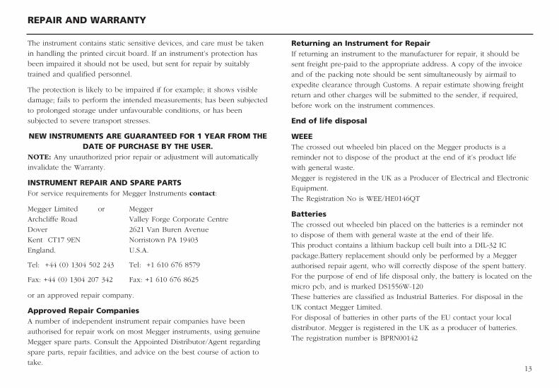
Returning an Instrument for RepairIf returning an instrument to the manufacturer for repair, it should be
sent freight pre-paid to the appropriate address. A copy of the invoice
and of the packing note should be sent simultaneously by airmail to
expedite clearance through Customs. A repair estimate showing freight
return and other charges will be submitted to the sender, if required,
before work on the instrument commences.
End of life disposal
WEEE
The crossed out wheeled bin placed on the Megger products is a
reminder not to dispose of the product at the end of it’s product life
with general waste.
Megger is registered in the UK as a Producer of Electrical and Electronic
Equipment.
The Registration No is WEE/HE0146QT
Batteries
The crossed out wheeled bin placed on the batteries is a reminder not
to dispose of them with general waste at the end of their life.
This product contains a lithium backup cell built into a DIL-32 IC
package.Battery replacement should only be performed by a Megger
authorised repair agent, who will correctly dispose of the spent battery.
For the purpose of end of life disposal only, the battery is located on the
micro pcb, and is marked DS1556W-120
These batteries are classified as Industrial Batteries. For disposal in the
UK contact Megger Limited.
For disposal of batteries in other parts of the EU contact your local
distributor. Megger is registered in the UK as a producer of batteries.
The registration number is BPRN00142
REPAIR AND WARRANTY
13
The instrument contains static sensitive devices, and care must be taken
in handling the printed circuit board. If an instrument’s protection has
been impaired it should not be used, but sent for repair by suitably
trained and qualified personnel.
The protection is likely to be impaired if for example; it shows visible
damage; fails to perform the intended measurements; has been subjected
to prolonged storage under unfavourable conditions, or has been
subjected to severe transport stresses.
NEW INSTRUMENTS ARE GUARANTEED FOR 1 YEAR FROM THE DATE OF PURCHASE BY THE USER.
NOTE: Any unauthorized prior repair or adjustment will automatically
invalidate the Warranty.
INSTRUMENT REPAIR AND SPARE PARTSFor service requirements for Megger Instruments contact:
Megger Limited or Megger
Archcliffe Road Valley Forge Corporate Centre
Dover 2621 Van Buren Avenue
Kent CT17 9EN Norristown PA 19403
England. U.S.A.
Tel: +44 (0) 1304 502 243 Tel: +1 610 676 8579
Fax: +44 (0) 1304 207 342 Fax: +1 610 676 8625
or an approved repair company.
Approved Repair CompaniesA number of independent instrument repair companies have been
authorised for repair work on most Megger instruments, using genuine
Megger spare parts. Consult the Appointed Distributor/Agent regarding
spare parts, repair facilities, and advice on the best course of action to
take.

14
M
Megger LimitedArchcliffe Road DoverKent CT17 9EN ENGLAND T +44 (0)1 304 502101 F +44 (0)1 304 207342
Megger4271 Bronze Way Dallas TX 75237-1017 USAT +1 800 723 2861 T +1 214 330 3203 F +1 214 337 3038
Megger Z.A. Du Buisson de la Couldre 23 rue Eugène Henaff78190 TRAPPES France T +33 (1) 30.16.08.90F +33 (1) 34.61.23.77
Megger products are distributed in 146 countries worldwide.
This instrument is manufactured in the United Kingdom.The company reserves the right to change the specification or design without prior notice. Megger is a registered trademark
DLRO600_UG_EN_V09 10/13www.megger.com


![V09-vodni_udar [557,94 KiB]](https://img.pdfslide.net/doc/110x75/588dbcff1a28ab53218bdb7a/v09-vodniudar-55794-kib.jpg)