Embed Size (px)
Citation preview

358 Technical Gazette 25, 2(2018), 358-367
ISSN 1330-3651 (Print), ISSN 1848-6339 (Online) https://doi.org/10.17559/TV-20160802143634 Original scientific paper
DLWUC: Distance and Load Weight Updated Clustering-Based Clock Distribution for SOC Architecture
A. SRIDEVI, V. LAKSHMIPRABHA
Abstract: High-clock skew variations and degradation of driving ability of buffers lead to an additional power dissipation in Clock Distribution Network (CDN) that increases the dimensionality of buffers and coordination among flip-flops. The manual threshold level to predict the Region of Interest (ROI) is not applicable in clustering process due to the complexities of excessive wire length and critical delay. This paper proposes the Distance and Load Weight Updated Clustering (DLWUC) to determine the suitable position of logical components. Initially, the DLWUC utilizes the Hybrid Weighted Distance (HWD) to estimate the distance and construct the distance matrix. The weight value extracted from the sorted distance matrix facilitates the projection of buffers. The updated weight value serves as the base for clustering with labeled outputs. The placement of buffer at the suitable place from load weight updated clustering provides the necessary trade-off between clock provision and load balance. The DLWUC discussed in this paper reduces the size of buffers, skew, power and latency compared to the existing topologies.
Keywords: buffers placement; Clock Distribution Network (CDN); clock mesh; clustering; Flip Flop (FF); Tree based CDN
1 INTRODUCTION
Dimensionality reduction and the minimum power supply are the major issues for progressive scaling of Integrated Circuit (IC) fabrication technologies. The utilization of minimal width transistors with the constant ion deposited charges makes the circuit as vulnerable to soft errors called Single Event Effects (SEE) [1]. The entire circuits of IC are controlled by Clock Distribution Network (CDN) and hence the hardening process is difficult. The presence of extreme node proximities in the advanced bulk CMOS technologies provides the strong sharing of the charges among the nodes called single event behaviors. Hence, the hardened designs are highly vulnerable to the node proximities in the advanced technologies. The identification and the separation of critical nodes in the layout improve the single-event sensitivity of hardened designs. The error-aware positioning -based layout designs (LEAP) [2] efficiently handle the charge sharing. The rearranging of transistor layout by using the LEAP method minimizes the single event effects on the circuit output. Hence, the research studies focus on the layout minimization techniques to reduce the area, power with high-speed operation.
The power dissipation in CDN is high due to the participation of high-speed processors in the IC fabrication. Hence, the driving of timing elements is the major task with the resonant clocking process. The operational inabilities are outside the limited range that requires core power management schemes. The interactions between the inductors and nearby wires cause the noise implications that lead to challenges in achieving the efficient LC resonance. The extent of inductive coupling to the nearby conductors and the dependence of inductive winding resistance efficiently achieve the good system quality factor. The dynamic power consumption is higher due to the following reasons: dominant effect of leakage power, maximum insertion delay and the low swing technology. Hence, the evolution of low swing clock trees in research studies efficiently reduces the power consumption.
The multi-power modes utilization reduces the power consumption significantly in clock is driven modules.
But, the minimization of clock skew is the difficult task due to the wide supply voltage levels. The set of modules utilized to remove the clock skew under various power domains is called Power Mode Aware Buffers (PMAB) [3]. Based on the power modes, the supply voltage level is changed to assure the dynamic operation. The introduction of the numerous advanced nodes and their dynamic operation cause the SEE in the IC fabrication process by the radiation particles. The failure in the clock network disrupts the operation in IC fabrication drastically. The pre-mesh clock tree-based hardening still introduces the significant number of errors. With the consideration of circuit complexity, clock generation components utilize the Digital Phase Locked Loops (DPLLs) [4] to minimize the jitter effectively.
The major concern in IC-based applications is the power consumption due to the following factors: design complexities, high integration, and supply voltage scaling issues. The CDN consumes the 20-45 % and the flip-flops consume 90 % of total on-chip power due to the increase of pipeline stages. A number of pipeline stages increases the number of flip-flops and the total length of the clock network. To overcome these issues, research studies introduce the Low-Swing (LS) signaling topologies [5] to reduce the dynamic power consumption for long interconnections. The high-clock net capacitance in CDN requires an extension of the operation of clock network in near-threshold voltages. Reliable LS clock achievement with less power consumption is the major concern in CDN-based IC and it is challengeable due to the following issues: • Low voltage-based clock buffers operation increases
the insertion delay that leads to higher clock skew• Driven ability level degradation• LS clock signal and the flip-flop integration increases
the clock-Q-delay that leads to excessive powerconsumption.
The detailed study conveys that the prediction / localization of best placement for the buffers and the merging of the flip-flop are the necessary stages to provide the trade-off between the high efficiency and low circuit complexity. Clustering algorithms play a major

A. SRIDEVI, V. LAKSHMIPRABHA: DLWUC: Distance and Load Weight Updated Clustering-Based Clock Distribution for SOC Architecture
Tehnički vjesnik 25, 2(2018), 358-367 359
role in buffer placement prediction. The weight updating-based flip-flop merging and the optimal buffer allocation predicts the best location for the respective buffer. These clustering methods use manual threshold effect to predict the Region of Interest (ROI) that increases the wire length and critical path delay.
This paper focuses on the load balance with the suitable clock provision by implementing the novel Distance and Load Weight Updated Clustering (DLWUC) model. The technical contributions of proposed work are listed as follows: • A measure of distance between the particles
constructs the distance matrix and the sorting of its elements in the ascending order (based on weight values) provides the relevant value of the load in clustering.
• The placement of buffer at the center of weight update-based clustering and the application of Hybrid Tree (HT) provide the trade-off between load balance and the clock signal provision effectively.
• The construction of Netlist file for FPGA architecture with the DLWUC-HT based locational information reduces the critical path delay, area consumption and wire length effectively compared to existing methods.
Section 2 presents a description of the previous
research which is relevant to the Clock Distribution Networks and its difficulties. Section 3 involves the detailed description of the implementation of proposed Distance and Load Weight Updated Clustering (DLWUC) model based CDN. Section 4 presents the performance analysis. This paper concludes in Section 5.
2 RELATED WORK
The continuous increase in frequency and resources of clock maximize the power consumption. Hence, the several research studies focused on the minimization of clock power. This section discusses the issues in the topology design and constraints to minimize the power consumption. Due to the capability of storing the energy in the inductors, the resonant clock networks provide the power saving effectively. Hu et al. [6] proposed the first automated algorithm called resonant clock synthesis (ROCKS) including distributed LC tank placement and novel AC-based resonant grid buffer incremental placement optimization. Ahn et al. [7] employed the power reduction techniques called Dynamic Voltage Frequency Scaling (DVFS) on the resonant network to maximize the synergy effect for the reduction in power consumption. They proposed the two-phase synthesis algorithm with the inductor allocation problem and the resizing adjustable buffers. The utilization of swing inverters at clock port of 3 D models was higher. Esmaeili et al. [8] introduced the new FF for low swing LC resonant clocking scheme which reduced the swing inverters effectively. The high-frequency supply voltage VCC drop in LC models affected the operational performance and energy efficiency when they were used in the design of microprocessors. While the ion deposited charges are constant, the diminishing of drive currents make the circuits vulnerable to soft errors called Single Event Effects (SEE). The Radiation Hardening by Design
(RHBD) approaches mitigated the soft error vulnerabilities effectively. Chellappa et al. [1] described the RHBD Clock Distribution Network (CDN) that synchronized the signals by using the Integrated Circuits (IC) in the presence of Single Event Transistors (SET). The RHBD utilized the techniques to reduce the jitter and detected the error due to SET. An effective layout design is a major requirement to reduce the error rate. Lilja et al. [2] performed alpha, neutron and heavy ion single event measures on the hardened Flip-Flop (FF) design in bulk CMOS technology. The layout optimization involved the analysis, design and the simulation of conventional FF design.
The inclusion of alpha and proton particles did not introduce the errors in clock networks. But, the participation of heavy ions caused the huge size errors in buffered clock tree structure. Wang et al. [9] presented and evaluated the two type of clock networks such as clock meshes and the buffered clock tree. They achieved more robustness to SET with the high-protection of buffered clock tree. The significant reduction in power consumption with power density and timing slack require the clock mesh and synthesis approaches. Lu et al. [10] performed post-placement stage with three major steps as feasible region construction, mesh grid wire generation and placement and incremental register placement. The buffers post placement significantly reduced the power dissipation, wire length and timing slack. The introduction of dynamically adaptive clock distribution models mitigated the effects of high-frequency voltage. Bowman et al. [11] integrated the tunable length delay before clock distribution. The prevention of degradation in timing margin by tunable length delay models allowed the sufficient response time for dynamic adaptation. The functional faults occur in CDN due to the effect of clock skew variations on timing margin. To overcome this problem, Abdelhadi et al. [12] presented an algorithm which combined the non-uniform meshes and Un-Buffered Tree (UBT). They tested the proposed UBT with the circuits from ISCAS89 benchmark suite and compared with the various mesh optimization works. Sassone et al. [13] analyzed the clock skew variations due to the non-uniform temperature profiles in a tree based CDNs. The low voltage operation of CDN induced the Process, Voltage, and Temperature (PVT) variation problem.
The alteration in radiance effects and the abnormal behavior in the system required the representation of signal by the CDNs. Chipana et al. [14] analyzed the two types of CDN to investigate the sensitivity to the radiation threats. The comparison between the clock mesh and clock tree showed that the clock mesh has the higher sensitivity to the radiation threats. The achievement of good Q-factor was dependent on the winding resistance and the nearby inductive coupling. Physical constraints and the increase in area overhead limited the applicability of high-volume microprocessors. With maintenance of low clock skew, the resonant global CDN efficiently reduced the clock distribution power. Sathe et al. [15] implemented dual mode feature to minimize the area and average power dissipation for maximum constrained performance. The implementation of a core in conventional and resonant mode at frequencies higher
A. SRIDEVI, V. LAKSHMIPRABHA: DLWUC: Distance and Load Weight Updated Clustering-Based Clock Distribution for SOC Architecture
360 Technical Gazette 25, 2(2018), 358-367
than the natural frequency achieved the energy-efficient clocking. The increase in a number of pipeline stages maximized the number of FF and power consumption in two-mode operation. Sitik et al. [5] proposed the Low-Swing (LS) clocking methodology by using the circuit and algorithmic innovations. The primary components involved in the LS strategy were novel D-FF and the clock tree synthesis algorithm to satisfy the timing constraints. They proposed LS-DFF cell to maintain the clock-to-Q delay with the power saving capabilities. Sitik et al. [16] introduced the Fin-FET-based LS methodology for a preservation of dynamic power to minimize the above three negative issues. With the scaled performance constraints, the FinFET models improved the dynamic power savings compared to conventional LS strategies. The factors limited LS applicability such as degradation in skew performance, power, data timing that initiated the Full-Swing (FS) topologies. The building of industrial Clock Tree Synthesis (CTS) required the optimization process for the conversion of FS. Sitik et al. [17] introduced the optimization method to reduce the clock switching power under skew bound. The introduction of heuristic optimization process kept the skew level of LS topology with the same skew budget originated from FS topology.
The presence of variations in the clock mesh or tree topologies caused the skew mismatches and the sorting of branches was the important task to reduce the mismatch problem. The research studies discussed yet did not cover the multi-corner analysis (sorting of branches) that provided the remarkable robustness against the variations in PVT. Sitik et al. [18] discussed the multi-voltage domain clock mesh designs based on a multi-corner analysis. The incompatible voltage levels of the clock drivers made the multiple voltage domain spanning infeasible. The matching of skew among the isolated meshes with the pre-mesh tree synthesis was the major requirement to tolerate the PVT variations. Predictive MOSFET models were the major requirement in the circuit design and co-optimization research studies. Sinha et al. [19] developed the predictive technology model files for sub-20nm multi-gate transistors. The 2011 ITRS roadmap integrated with the earlier stage silicon results were obtained based on the MOSFET scaling theory. The Power Mode Aware Buffers (PMAB) removed the clock skew effectively. Chou et al. [3] presented the new PMAB architecture with two sub-modules serially connected buffers under different voltage levels. The low-voltage level was used to remove the clock skew in front side sub-PMA module and the high voltage level removed the clock skew problem in back side sub-PMAB. With an account of internal and external noise sources and associated filtering properties, Phase Locked Loops (PLLs) provided the best jitter performance. Kuan et al. [20] proposed the loop gain optimization technique for PLL to attain the loops gain automatically for jitter minimization. They discussed the impact of loop latency on the stability and provided the good agreement compared to behavioral simulations.The development of dedicated ICs extends its applicability to the real-time system creation i.e. neuromorphic system. Scholze et al. [21] considered the bandwidth requirements with the density of large size components involved. They
presented the VLSI realization on System on Chip (SoC) to improve the throughput of the system. Support of wide range of radio standards and the high energy efficiency were the major requirements for Multiprocessors Systems-on-Chip (MPSoC).
The single Phase Locked Loop (PLL) was not suitable for the design of MPSoC due to the huge power management techniques and the clock quality demands. Hence, the low chip area and low-power All Digital Phase Locked Loops (ADPLL) provided an alternative solution. Höppner et al. [4] presented the ADPLL clock generator for Globally Asynchronous and Locally Synchronous (GALS) multiprocessors. With the consideration of low circuit design complexity, the evolution of bang-bang ADPLL supported the clock generation for high-speed links and memory interfaces that required the minimum jitter as mandatory. Höppner et al. [22] presented the Built-In Self-Calibration (BISC) to minimize the jitter for ADPLL circuits. On the basis of the addition of monitoring phase frequencies detector with the tunable cells allowed the on-chip binary comparisons. The adaptation of ADPLL filter coefficients efficiently minimized the jitter against PVT variations. Jeon et al. [23] enhanced the Clock and Data Recovery (CDR) jitter performance with the inherent Bang-Bang Phase Detector (BBPD). The adaptive adjustment loop gain on the basis of estimated jitter spectrum provides the PVT insensitive and power loop gain. They performed the jitter tolerance tests to show the effective tracking of low-frequency and filtering of high-frequency simultaneously. Jang et al. [24] proposed the ADPLL with phase frequency detector tracking of optimal loop gain for the low jitter. The formulation of autocorrelation function denoted the operating state of ADPLL on either non-linear or random noise regime. The employment of an adaptive loop gain controller and digital loop filter provided the automatic adjustments and the loop latency reduction.The similar properties of input / output waveform caused the time modeling of clock buffers as the challenging task compared to logical gates. Traditionally, look-up table approaches were used to obtain the buffer timing against the capacitance effects. Sitik et al. [25] proposed the timing estimation scheme that modeled the delay and skew variations as the linear equations. The linear-equation-based timing model provided the significant reduction in error rates and bypassed the costly LUT-based approaches.
Clock Distribution Problems in SOC environment: • The Single Event Error (SEE) rates were high [9] due
to the strong dependence of single event sensitivity. • The conventional LS strategies [5] faced the trade-off
issues in three dimensions such as dominant leakage power, more insertion delay and difficulties in driving DFF sinks.
• The multiple power mode operation significantly reduced the power consumption effectively. But, the clock skew minimization was difficult [19].
• The single PLL was unsuitable for the design of MPSoC due to the huge power management techniques [21] and the clock quality demands. The detailed study of traditional CDN topologies
conveyed that the trade-off between the clock provision

A. SRIDEVI, V. LAKSHMIPRABHA: DLWUC: Distance and Load Weight Updated Clustering-Based Clock Distribution for SOC Architecture
Tehnički vjesnik 25, 2(2018), 358-367 361
and load balance was required. A large number of buffer incorporation and the grouping of FFs were the major requirements to provide the necessary trade-off. Hence, the placement and the localization were the important issues in the trade-off provision.
3 DISTANCE AND LOAD WEIGHT UPDATED
CLUSTERING
The proposed distance and load weight update processes are helpful to predict the suitable position for the buffer to distribute the clock signal. In general, the clock tree topology contains two sections such as High-to-Low (HL) and Low-to-High (LH) as in Fig. 1.
Figure 1 Clock tree architecture
The HL and LH converters are the buffers that
convert the incoming clock signal from high to low swing and vice versa respectively. The low voltage clock signal applied to the chip ensures the low-power distribution network. When the signal passes through the network, the utilization of intermediate buffers is responsible for regeneration and the slew rate maintenance. The buffer insertion in post routing phases causes the delay and jitter values are maximum and hence the positioning and localization of buffer is the necessary stage to reduce them. The major criterion for the buffer insertion is the faster slew rate of input and sink node compared to given specification. The faster slew rate limits the slope effect of delay and controls the short-circuit power effectively. The major objective of this paper is to find out the location of buffer and the estimation of power dissipated is the prior task to location prediction. The total power dissipated includes two components as • Power dissipated by the buffers in the tree (Pb) • Power dissipated by the wires (Pw).
The location of buffers has a serious impact on the power dissipation significantly discussed as follows: • Number of buffers at the lowest stage of tree and the
transistors utilization increases the power dissipation • The wire downstream operation on low swing
increases the consumption of power per unit length of wire.
The insertion of buffer into the tree offers the separation of clock tree and it serves as the capacitance, separators for phase delay reduction. The pulsed latch designs offer the timing verification and minimum power consumption effectively. The high-level synthesis is the major requirement to adopt the pulsed latches in the design flow. The pulse generator is responsible for clock pulse and it consumes more power than the latches and buffer. The connection between the latches and buffer at the limited position and the communication between the nearby buffers forms the tree based network. There are three patterns in the clock generation listed as follows: • Separate pulse generation for each block (Small load
and large power consumption) • Single-pulse generation for overall FFs (large load
and small power consumption) • Separate clusters of pulse generation (small load and
small power consumption).
Case i: Small load and large power consumption: The load of each pulse generator is small in this case. But, the large number of pulse generators cause the high power consumption.
Case ii: Large load and small power consumption: The utilization of single pulse generator to drive the latches efficiently reduces the power consumption with the reduction of driver capacitance. The maximum fan-out constraint and the heavy output load degrade the clock pulsed waveform.
Case iii: Small load and small power consumption: The replacement of pulse generators with small size reduces the power consumption.
Since the clock pulse is sensitive to output load, the control of pulse generator load is necessary to prevent degradation in pulse. The factors considered to control the load of pulse generator are minimum driving load compared to tolerable load and the smaller pulsed latches than the maximum fan-out. The power consumption in pulsed latch circuits is higher and hence the reduction of pulse generator power is the critical issue in CDN design.
Problem formulation: The total capacitance of the clock tree contains interconnect, register and buffer. The register capacitance is certain in nature and the buffer capacitance is determined based on the skew and slew requirements. A number of buffers insertion at the leaf level of tree offers the effective tuning in delay of operation in components and thus skew is reduced. Hence, the clustering of components limits the number of buffers in leaf level, skew and interconnect capacitance. The analysis of the amount of wire length reduction is the quantification parameter for the quality of clustering algorithm. Hence, the power reduction problem is modelled as distance-based clustering to minimize the wire length as follows:
Input: A set of components Sc = (c1, c2, …, cn) with the location ( , )c ci ix y for component ci.
Output: A set of clusters SC = (C1, C2, …, Cm). The center location of cluster Ci is estimated by using
the following equations:
1 , , 1, 2,...,p
cj jC j ii
xx c C j p
p== ∈ =
∑ (1)

A. SRIDEVI, V. LAKSHMIPRABHA: DLWUC: Distance and Load Weight Updated Clustering-Based Clock Distribution for SOC Architecture
362 Technical Gazette 25, 2(2018), 358-367
1 , , 1, 2,...,p
cj jC j ii
yy c C j p
p== ∈ =
∑ (2)
Figure 2 Flow diagram of proposed work
Objective: To minimize the total wire length at the
leaf level of the clock tree by the mathematical formulation of wire length estimation is described as
( )1m
w c C c Ci c C j i j ij iL x x y y= ∈= − + −∑ ∑ (3)
Subject to the following constraints
{ }
1
0, 1, 2,...,0, , 1, 2,..., and
i
i j
m
i ci
C i mC C i j i m i j
C S=
≠ =
∩ = ∈ = ≠
=
With these constraints, this paper proposes the
distance-based clustering and load balanced weight update of clustering to predict the best placement for buffer. Fig. 2 shows the workflow prior to the buffer placement in leafs of hybrid tree. Initially, the components and their placement details from the netlist are extracted for suitable position of buffer. Then, the distance between the components is computed. Based on the distance measures, the binary matrix with the indices of 0s and 1s that denotes the connection between the components is either present or absent. Then, the maximum number of 1s are measured and computed the index corresponds to count value.
The elements of the binary matrix are updated by neglecting the connected components. The component list is updated based on the matrix elements. Once the cluster
matrix is formed, the weight value is updated based on load-partitioning. The index corresponding to the center portion is computed and it denotes the suitable position for buffers to distribute the clock signal. The major prior processes to find the position of buffers are listed as follows: • Hybrid weighed distance • Load partitioning based weight update. 3.1 Hybrid Weighed Distance
The sequence based representation serves as the base for initial floor plan. The floor plane layouts for pins and the components are formed using the Corner List (CL). The major properties of proposed algorithms are listed as follows: • If there are 𝑛𝑛 number of components placed into the
floor plan region, then the (n + 1) number of corners exists only if the width of the modules is not same.
• If the two components are same in size, then they are regarded as a single component. Fig. 3 shows the contest of example benchmark
circuit called ISPD2010 CNS which contains several IP cores.
Figure 3 ISPD 2010 CNS contest
The iterative processes in proposed algorithm form
the large cluster of registers in IP core. The presence of some empty clusters (no register chooses to join them) leads to failures. These failures arise due to the invalid conditions of (1) and (2). Hence, the center of the cluster is computed with the distance between the nearest neighbors. The mathematical formulation of distance is expressed as
2 2Δ Δx yD I I= + (4) where ΔIx, ΔIy – Component details with respect to the coordinates (x, y). The distance between the current component to the nearest cell existing means the connection is established. The binary matrix is constructed by using 1’s and 0’s. The value 1 represents the possible connection existing between the components and 0 denotes the absence of connection. The cluster matrix is obtained from the component details by using the following algorithm.

A. SRIDEVI, V. LAKSHMIPRABHA: DLWUC: Distance and Load Weight Updated Clustering-Based Clock Distribution for SOC Architecture
Tehnički vjesnik 25, 2(2018), 358-367 363
Hybrid Weighed Distance Input: Component details ‘I’ Output: Cluster matrix ‘T’ Step 1: Calculate the distance (D) between the
components and find the possible connection with the components by using (4)
Step 2: Estimate the nearest possible cells with (Dmin) Step 3: Extract the components present on Dmin Step 4: Create binary matrix for the location of
components, ‘B’. Step 5: Find Maximum number of value ‘1’ in that table
and identify the index, ‘𝑙𝑙’ Step 6: Extract the index connected to it,
E = idx(B{l}) Step 7: Consider centroid of the cluster,
C = l Step 8: Update the binary table by neglecting the
connected components by, B{E} = 0
Step 9: Update the cluster Matrix, Ti = {l, E} (1 < i < N)
Step 10: Repeat from Step 3 to 7 until the binary table becomes zero.
Then, the algorithm estimates the nearest possible
cells with the minimum distance value (Dmin). The components present on Dmin are extracted and then create the binary matrix. The maximum number of 1s that specify the connection between the components is measured and extracted index corresponds to the count value. Then, the index that corresponds to maximum number of 1’s is regarded as the center of cluster. Now, the binary matrix is updated by replacing the values with 0 for the connected components. Finally, the cluster matrix is updated with the new head and the leaf as follows: Ti = {l, E} (1 < i < N) (5) where: l and E are the cluster head and its leaf respectively; N – Number of components. Fig. 4 shows the formation of cluster of connected components with the root node.
Figure 4 Cluster formation for benchmark circuit
The cluster of components is formed by using the
distance and load weight based algorithm. But, the best placement is the investigating one according to the load conditions. Hence, the load partitioning based weight update is necessary to predict the suitable placement for buffer.
3.2 Load Portioning Based Weight Update
The buffers placement at the center of clusters causes the higher wirelength that leads to delay and excessive power consumption. Hence, the prediction of optimal location for the buffer is the necessary process. The algorithm for load partitioning-based weight update is listed as follows: Load partitioning based weight update Input: Cluster matrix ‘T’ Output: Placement position ‘P’ Step 1: Estimate average value of cluster matrix by using (6) Step 2: Estimate S.D. value of cluster matrix by using (7) Step 3: Estimate the window limit as,
( )2 2
( , )1
( )x yi
W V f x=
= −∑
{ }( ) ,f x A SD= Step 4: Calculate weight value of the extracted window
limit as, 2 2
eW Wx yWt
− +=
Step 5: Update the cluster matrix according to weight value.
( , )xy xy x yCL T Wt W W= × Step 6: Find distance for the cluster according to
minimum cluster weight
( )2( ) ( )( , )
min( )CL j CL k
U j kCL−
=
Step 7: Find minimum cluster index as centroid, min( )
ix UCent
N−
=
Step 8: If (Cemti < mean(cent)), P = Centi; End if;
The window limit to locate the components and
buffers is defined by fitness function f(x) containing the average (A) and standard deviation (SD) of cluster matrix (T) as follows:
1 1N M
iji j TA
M N= ==
×
∑ ∑ (6)
where M and N denote the row and column size of matrix
( ) 21
1 ( )M NiiSD T A
M N×
== −× ∑ (7)
{ }( ) ,f x A SD= (8)
The difference between the random vector
corresponds to the position and the fitness function decides the window limit (W(x,y)). The weight value that corresponds to the coordinates of window limit is used to

A. SRIDEVI, V. LAKSHMIPRABHA: DLWUC: Distance and Load Weight Updated Clustering-Based Clock Distribution for SOC Architecture
364 Technical Gazette 25, 2(2018), 358-367
update the cluster matrix. Now, the distance estimation is again performed for the updated minimum cluster weight. The index that corresponds to the minimum distance is regarded as the necessary position to locate buffer. Fig. 5 and 6 show the locating of buffers with suitable positions to reduce the wire length and delay.
Figure 5 Buffer placement
Figure 6 Weight update-based buffer placement
Then, the buffers located in suitable locations are
connected to the root as shown in Fig. 7.
Figure 7 Interconnection of buffers with root node
Once the buffers are placed at the suitable position,
the CDN follows the hybrid tree topology (H-tree+ Binary tree) to reduce the wire length and power consumption. The sectors in the hybrid tree contain the set of spiral inductors and capacitors (LC) and driving buffers. The resonance nature of LC circuits that causes the energy variation instead of dissipation efficiently reduces the power consumption. The parameters for hybrid tree are width wi, length li and thickness ti of each sector (i), clock frequency (fo) and capacitive load Cl as
H = f(wi, li, ti, fo, Cl)i (9)
The total number of nodes handling by the hybrid tree topology is more than the traditional H-tree architecture that leads to large components handling with minimum wire length and delay.
4 PERFORMANCE ANALYSIS
This section discusses the effectiveness of the proposed DLWUC algorithm with the benchmark circuits of ISCAS’89 and ISPD 2010 [26] and ISCAS’89 [27]. The ISCAS’89 includes the 31 digital sequential circuits that are distributed on tape to the sequential test generation participants. There are two files in the ISCAS’89 such as generic gate level netlist and equivalence collapsed faults. The proposed DLWUC offers the significant reduction in the following parameters: wirelength (nanometer), channel width (nanometer) and delay (nanoseconds) compared to the traditional clustering methods [28, 29] for the benchmark circuits CKT1 to CKT10 as shown in Tab. 1, 2 and 3 respectively.
Table1 Wirelength analysis CKT Traditional Clustering DLWUC
1 23 18 2 25 21 3 26 20 4 26 23 5 21 19 6 20 15 7 19 13 8 17 14 9 21 17
10 15 11
Table 2 Channel width analysis CKT Traditional Clustering DLWUC
1 78 73 2 82 77 3 85 78 4 85 81 5 74 68 6 73 70 7 70 64 8 68 64 9 74 69
10 62 58
Table 3 Delay Analysis CKT Traditional Clustering DLWUC
1 26.4 21.82563 2 25.8 22.43196 3 25 20.35503 4 25.4 20.48353 5 26 23.87316 6 26 21.13314 7 27 24.33837 8 26.5 22.55228 9 29 24.55861
10 27 23.12255
The circuits CKT1-CKT6 are created using the ISCAS’89 to validate the number of buffers requirement (Power Mode Aware Buffers (PMAB), Clock Buffers (CKB) and Delay Buffers(DLB)) [3]. The ISPD 2010 benchmark circuits used to validate the effectiveness of proposed algorithm over the existing obstacle avoiding

A. SRIDEVI, V. LAKSHMIPRABHA: DLWUC: Distance and Load Weight Updated Clustering-Based Clock Distribution for SOC Architecture
Tehnički vjesnik 25, 2(2018), 358-367 365
[30], clustering-based Clock Tree Synthesis (CTS) models [28, 29] . The comparative analysis shows that the proposed algorithm efficiently achieves the reduction in wirelength, skew and power consumption effectively. 4.1 Buffer Analysis
The comparison between the existing Multi-mode Power Aware Buffer (MPAB), Integer Linear Programming (ILP) and proposed DLWUC regarding the buffer utilization shows the reduction due to the load portioning based weight update. Tab. 4 presents the comparative analysis regarding the buffer consumption in existing and proposed DLWUC model.
The hybrid weight based clustering and load partitioning based weight update reduce the number of delay buffers into 2 and 4 for CKT3 and CKT6. In
existing methods, the ILP provide the significant reduction in DLB compared to MPAB. But, the modification in clustering based on the load partition-based weight update in proposed work reduces the DLB by 33.33 and 20 % for CKT3 and CKT6. 4.2 Clock Latency Analysis
The comparison between the existing Multi-mode Power Aware Buffer (MPAB), Integer Linear Programming (ILP) and proposed DLWUC methods regarding the clock latency analysis shows that the proposed DLWUC offers the significant reduction in the minimum and maximum values (ns). Tab. 5 presents the comparative analysis regarding the clock latency in existing and proposed DLWUC model.
Table 4 Buffer consumption analysis
Benchmark Circuits
MPMAB ILP DLWUC #PMAB #CKB #DLB #PMAB #CKB #DLB #PMAB #CKB #DLB
CKT1 2 9 6 2 48 1 2 46 1 CKT2 2 34 1 2 41 1 2 45 1 CKT3 2 5 10 2 49 3 2 48 2 CKT4 2 12 2 2 14 0 2 15 0 CKT5 2 30 23 2 22 0 2 25 0 CKT6 2 9 66 2 48 5 2 50 4
Table 5 Clock latency analysis
Benchmark Circuits
CONV MPMAB ILP DLWUC Min (ns) Max (ns) Min (ns) Max (ns) Min (ns) Max (ns) Min (ns) Max (ns)
CKT1 13.2 13.5 0.16 14.53 14.6 14.89 10.72 15.63 CKT2 13.26 13.56 0.72 14.53 14.26 14.56 10.41 15.22 CKT3 8.86 9.16 0.16 9.72 9.38 9.68 6.65 7.04 CKT4 16.53 16.8 0.12 19.3 16.8 16.85 11.42 14.7 CKT5 8.81 9.1 0.26 21.22 9.34 9.62 6.67 8.83 CKT6 13.2 13.5 0.15 15.99 14.6 14.89 10.72 12.18
In existing methods, the ILP provides the minimum
latency values compared to conventional PMAB (CONV), MPAB. The DLWUC is further reduced clock latency value due to the hybrid methods. For example, the minimum and maximum clock latency values for CKT1 are 14.6 and 14.89 ns. But, the latency values for DLWUC are 10.72 and 15.63 ns which are 26.58% less and 4.73% more compared to ILP method. For other circuits (CKT6), the proposed DLWUC provides 10.72 and 12.18 ns that are 26.58 and 18.2% less compared to ILP models. 4.3 SPL Analysis
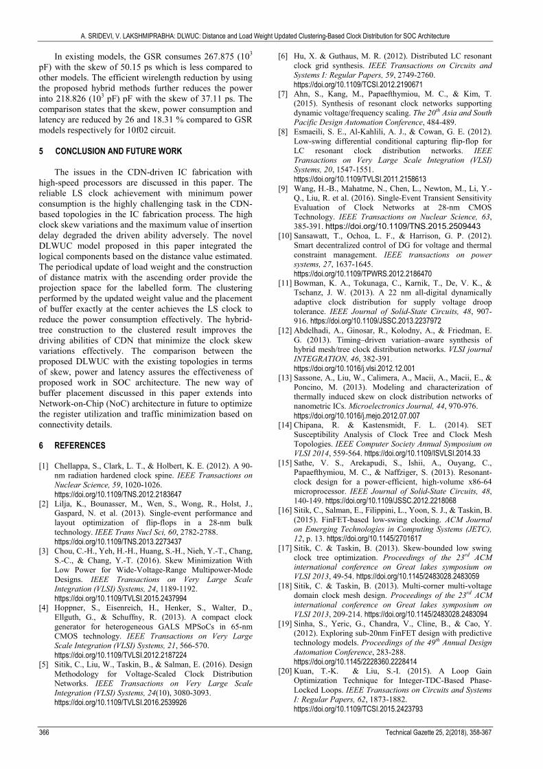
This section discusses the comparative analysis of Skew (pico seconds (ps)), Power (in terms of capacitance limit (pico Farad)) [31] and Latency (pico seconds (ps)) (SPL) variations for existing obstacle avoiding, clustering and K-means based CTS models with the proposed DLWUC. The 10f01 and 10f02 circuits from the ISPD 2010 benchmark are used to validate the performance of proposed and existing models. Tab. 6 lists the SPL variations for 10f01 circuits.
In existing models, the GSR consumes 142.847 (103 pF) with the latency of 763.59 ps which is less compared to other models. The efficient wirelength reduction by using the proposed hybrid methods further reduces the power into 125.309 (103 pF) with the latency of 753.25
ps. The comparison states that the power consumption and latency are reduced by 12.27 and 6.32 % compared to GSR models respectively for 10f01 circuit. Fig. 8 shows the comparative analysis between the SPL variations (10f02 circuits) for existing and proposed models respectively.
Table 6 Comparative analysis of SPL for 10f01
Methods Skew (ps) Power (103 pF)
Max. Latency (ps)
Obstacle Avoiding 45.22 194.024 798.97 Clustering 79.19 151.773 791.25 KMR 30.67 153.885 756.28 KSR 46.81 146.083 779.67 GSR 34.67 142.847 763.59 DLWUC 31.27 125.309 753.25
Figure 8 Skew and power variations
A. SRIDEVI, V. LAKSHMIPRABHA: DLWUC: Distance and Load Weight Updated Clustering-Based Clock Distribution for SOC Architecture
366 Technical Gazette 25, 2(2018), 358-367
In existing models, the GSR consumes 267.875 (103 pF) with the skew of 50.15 ps which is less compared to other models. The efficient wirelength reduction by using the proposed hybrid methods further reduces the power into 218.826 (103 pF) pF with the skew of 37.11 ps. The comparison states that the skew, power consumption and latency are reduced by 26 and 18.31 % compared to GSR models respectively for 10f02 circuit. 5 CONCLUSION AND FUTURE WORK
The issues in the CDN-driven IC fabrication with high-speed processors are discussed in this paper. The reliable LS clock achievement with minimum power consumption is the highly challenging task in the CDN-based topologies in the IC fabrication process. The high clock skew variations and the maximum value of insertion delay degraded the driven ability adversely. The novel DLWUC model proposed in this paper integrated the logical components based on the distance value estimated. The periodical update of load weight and the construction of distance matrix with the ascending order provide the projection space for the labelled form. The clustering performed by the updated weight value and the placement of buffer exactly at the center achieves the LS clock to reduce the power consumption effectively. The hybrid-tree construction to the clustered result improves the driving abilities of CDN that minimize the clock skew variations effectively. The comparison between the proposed DLWUC with the existing topologies in terms of skew, power and latency assures the effectiveness of proposed work in SOC architecture. The new way of buffer placement discussed in this paper extends into Network-on-Chip (NoC) architecture in future to optimize the register utilization and traffic minimization based on connectivity details. 6 REFERENCES [1] Chellappa, S., Clark, L. T., & Holbert, K. E. (2012). A 90-
nm radiation hardened clock spine. IEEE Transactions on Nuclear Science, 59, 1020-1026.
https://doi.org/10.1109/TNS.2012.2183647 [2] Lilja, K., Bounasser, M., Wen, S., Wong, R., Holst, J.,
Gaspard, N. et al. (2013). Single-event performance and layout optimization of flip-flops in a 28-nm bulk technology. IEEE Trans Nucl Sci, 60, 2782-2788.
https://doi.org/10.1109/TNS.2013.2273437 [3] Chou, C.-H., Yeh, H.-H., Huang, S.-H., Nieh, Y.-T., Chang,
S.-C., & Chang, Y.-T. (2016). Skew Minimization With Low Power for Wide-Voltage-Range Multipower-Mode Designs. IEEE Transactions on Very Large Scale Integration (VLSI) Systems, 24, 1189-1192.
https://doi.org/10.1109/TVLSI.2015.2437994 [4] Hoppner, S., Eisenreich, H., Henker, S., Walter, D.,
Ellguth, G., & Schuffny, R. (2013). A compact clock generator for heterogeneous GALS MPSoCs in 65-nm CMOS technology. IEEE Transactions on Very Large Scale Integration (VLSI) Systems, 21, 566-570.
https://doi.org/10.1109/TVLSI.2012.2187224 [5] Sitik, C., Liu, W., Taskin, B., & Salman, E. (2016). Design
Methodology for Voltage-Scaled Clock Distribution Networks. IEEE Transactions on Very Large Scale Integration (VLSI) Systems, 24(10), 3080-3093.
https://doi.org/10.1109/TVLSI.2016.2539926
[6] Hu, X. & Guthaus, M. R. (2012). Distributed LC resonant clock grid synthesis. IEEE Transactions on Circuits and Systems I: Regular Papers, 59, 2749-2760.
https://doi.org/10.1109/TCSI.2012.2190671 [7] Ahn, S., Kang, M., Papaefthymiou, M. C., & Kim, T.
(2015). Synthesis of resonant clock networks supporting dynamic voltage/frequency scaling. The 20th Asia and South Pacific Design Automation Conference, 484-489.
[8] Esmaeili, S. E., Al-Kahlili, A. J., & Cowan, G. E. (2012). Low-swing differential conditional capturing flip-flop for LC resonant clock distribution networks. IEEE Transactions on Very Large Scale Integration (VLSI) Systems, 20, 1547-1551.
https://doi.org/10.1109/TVLSI.2011.2158613 [9] Wang, H.-B., Mahatme, N., Chen, L., Newton, M., Li, Y.-
Q., Liu, R. et al. (2016). Single-Event Transient Sensitivity Evaluation of Clock Networks at 28-nm CMOS Technology. IEEE Transactions on Nuclear Science, 63, 385-391. https://doi.org/10.1109/TNS.2015.2509443
[10] Sansawatt, T., Ochoa, L. F., & Harrison, G. P. (2012). Smart decentralized control of DG for voltage and thermal constraint management. IEEE transactions on power systems, 27, 1637-1645.
https://doi.org/10.1109/TPWRS.2012.2186470 [11] Bowman, K. A., Tokunaga, C., Karnik, T., De, V. K., &
Tschanz, J. W. (2013). A 22 nm all-digital dynamically adaptive clock distribution for supply voltage droop tolerance. IEEE Journal of Solid-State Circuits, 48, 907-916. https://doi.org/10.1109/JSSC.2013.2237972
[12] Abdelhadi, A., Ginosar, R., Kolodny, A., & Friedman, E. G. (2013). Timing–driven variation–aware synthesis of hybrid mesh/tree clock distribution networks. VLSI journal INTEGRATION, 46, 382-391.
https://doi.org/10.1016/j.vlsi.2012.12.001 [13] Sassone, A., Liu, W., Calimera, A., Macii, A., Macii, E., &
Poncino, M. (2013). Modeling and characterization of thermally induced skew on clock distribution networks of nanometric ICs. Microelectronics Journal, 44, 970-976.
https://doi.org/10.1016/j.mejo.2012.07.007 [14] Chipana, R. & Kastensmidt, F. L. (2014). SET
Susceptibility Analysis of Clock Tree and Clock Mesh Topologies. IEEE Computer Society Annual Symposium on VLSI 2014, 559-564. https://doi.org/10.1109/ISVLSI.2014.33
[15] Sathe, V. S., Arekapudi, S., Ishii, A., Ouyang, C., Papaefthymiou, M. C., & Naffziger, S. (2013). Resonant-clock design for a power-efficient, high-volume x86-64 microprocessor. IEEE Journal of Solid-State Circuits, 48, 140-149. https://doi.org/10.1109/JSSC.2012.2218068
[16] Sitik, C., Salman, E., Filippini, L., Yoon, S. J., & Taskin, B. (2015). FinFET-based low-swing clocking. ACM Journal on Emerging Technologies in Computing Systems (JETC), 12, p. 13. https://doi.org/10.1145/2701617
[17] Sitik, C. & Taskin, B. (2013). Skew-bounded low swing clock tree optimization. Proceedings of the 23rd ACM international conference on Great lakes symposium on VLSI 2013, 49-54. https://doi.org/10.1145/2483028.2483059
[18] Sitik, C. & Taskin, B. (2013). Multi-corner multi-voltage domain clock mesh design. Proceedings of the 23rd ACM international conference on Great lakes symposium on VLSI 2013, 209-214. https://doi.org/10.1145/2483028.2483094
[19] Sinha, S., Yeric, G., Chandra, V., Cline, B., & Cao, Y. (2012). Exploring sub-20nm FinFET design with predictive technology models. Proceedings of the 49th Annual Design Automation Conference, 283-288.
https://doi.org/10.1145/2228360.2228414 [20] Kuan, T.-K. & Liu, S.-I. (2015). A Loop Gain
Optimization Technique for Integer-TDC-Based Phase-Locked Loops. IEEE Transactions on Circuits and Systems I: Regular Papers, 62, 1873-1882.
https://doi.org/10.1109/TCSI.2015.2423793

A. SRIDEVI, V. LAKSHMIPRABHA: DLWUC: Distance and Load Weight Updated Clustering-Based Clock Distribution for SOC Architecture
Tehnički vjesnik 25, 2(2018), 358-367 367
[21] Scholze, S., Eisenreich, H., Höppner, S., Ellguth, G., Henker, S., Ander, M. et al. (2012). A 32GBit/s communication SoC for a waferscale neuromorphic system. VLSI journal INTEGRATION, 45, 61-75.
https://doi.org/10.1016/j.vlsi.2011.05.003 [22] Höppner, S., Partzsch, J., Neumann, J., Schüffny, R., &
Mayr, C. (2016). A Calibration Technique for Bang-Bang ADPLLs Using Jitter Distribution Monitoring. IEEE Transactions on Very Large Scale Integration (VLSI) Systems, 24(12). https://doi.org/10.1109/TVLSI.2016.2558664
[23] Jeon, H.-J., Kulkarni, R., Lo, Y.-C., Kim, J., & Silva-Martinez, J. (2013). A bang-bang clock and data recovery using mixed mode adaptive loop gain strategy. IEEE Journal of Solid-State Circuits, 48, 1398-1415.
https://doi.org/10.1109/JSSC.2013.2253414 [24] Jang, S., Kim, S., Chu, S.-H., Jeong, G.-S., Kim, Y., &
Jeong, D.-K. (2015). An optimum loop gain tracking all-digital PLL using autocorrelation of bang–bang phase-frequency detection. IEEE Transactions on Circuits and Systems II: Express Briefs, 62, 836-840.
https://doi.org/10.1109/TCSII.2015.2435691 [25] Sitik, C., Lerner, S., & Taskin, B. (2014). Timing
characterization of clock buffers for clock tree synthesis. 2014 IEEE 32nd International Conference on Computer Design (ICCD), 230-236.
https://doi.org/10.1109/ICCD.2014.6974686 [26] Adya, S. & Markov, I. (2002). ISPD02 IBM-MS mixed-
size placement benchmarks, ed. http://vlsicad.eecs.umich.edu/BK/ISPD02bench/ [27] Kim, J., Joo, D., & Kim, T. (2016). Optimal utilization of
adjustable delay clock buffers for timing correction in designs with multiple power modes. Integration, the VLSI Journal, 52, 91-101. https://doi.org/10.1016/j.vlsi.2015.08.005
[28] Deng, C., Cai, Y.-C., & Zhou, Q. (2015). Register Clustering Methodology for Low Power Clock Tree Synthesis. Journal of Computer Science and Technology, 30, 391-403. https://doi.org/10.1007/s11390-015-1531-4
[29] Shelar, R. S. (2007). An efficent clustering algorithm for low power clock tree synthesis. Proceedings of the 2007 International Symposium on Physical Design, 181-188.
https://doi.org/10.1145/1231996.1232037 [30] Niu, F., Zhou, Q., Yao, H., Cai, Y., Yang, J., & Sze, C. N.
(2011). Obstacle-avoiding and slew-constrained buffered clock tree synthesis for skew optimization. Proceedings of the 21st edition of the great lakes symposium on Great lakes symposium on VLSI 2011, 199-204.
https://doi.org/10.1145/1973009.1973049 [31] ISPD 2010. (2010). High Performance Clock Network
Synthesis Contest. http://archive.sigda.org/ispd/contests/ 10/ispd10cns.html
Contact information: A. SRIDEVI, Professor, Corresponding author ECE department, SreeSakthi Engineering College, 839/1-D, Bettathapuram, Pudur, Karamadai, Coimbatore - 641 104, Tamil Nadu, India [email protected] Dr. V. LAKSHMIPRABHA, Principal Government College of Technology, Coimbatore, Tamil Nadu, India