Embed Size (px)
Citation preview
May 2005
DESIGN MANUAL FOR ROADS AND BRIDGES
VOLUME 1 HIGHWAY STRUCTURES:APPROVAL PROCEDURESAND GENERAL DESIGN
SECTION 3 GENERAL DESIGN
PART 17
BD 90/05
DESIGN OF FRP BRIDGES ANDHIGHWAY STRUCTURES
SUMMARY
This Departmental Standard gives the requirements forthe design of highway bridge and structures using FibreReinforced Polymer materials.
INSTRUCTIONS FOR USE
This is a new document to be incorporated into theManual.
1. Remove Contents pages for Volume 1.
2. Insert New Contents pages for Volume 1 datedMay 2005.
3. Insert BD 90/05 into Volume 1, Section 3,Part 17.
4. Please archive this sheet as appropriate.
Note: A quarterly index with a full set of VolumeContents Pages is available separately from TheStationery Office Ltd.
BD 90/05
Design of FRP Bridges andHighway Structures
Summary: This Departmental Standard gives the requirements for the design of highwaybridge and structures using Fibre Reinforced Polymer materials.
DESIGN MANUAL FOR ROADS AND BRIDGES
THE HIGHWAYS AGENCY
SCOTTISH EXECUTIVE
WELSH ASSEMBLY GOVERNMENTLLYWODRAETH CYNULLIAD CYMRU
THE DEPARTMENT FOR REGIONAL DEVELOPMENTNORTHERN IRELAND

Volume 1 Section 3Part 17 BD 90/05
May 2005
REGISTRATION OF AMENDMENTS
Amend Page No Signature & Date of Amend Page No Signature & Date ofNo incorporation of No incorporation of
amendments amendments
Registration of Amendments

Volume 1 Section 3Part 17 BD 90/05
May 2005
REGISTRATION OF AMENDMENTS
Amend Page No Signature & Date of Amend Page No Signature & Date ofNo incorporation of No incorporation of
amendments amendments
Registration of Amendments
VOLUME 1 HIGHWAY STRUCTURES:APPROVAL PROCEDURESAND GENERAL DESIGN
SECTION 3 GENERAL DESIGN
PART 17
BD 90/05
DESIGN OF FRP BRIDGES ANDHIGHWAY STRUCTURES
Contents
Chapter
1. Introduction
2. Components and Sub-Assemblies
3. Overview of Design
4. Design Requirements
5. General Requirements
6. Construction and Maintenance
7. References
8. Enquiries
Annex A Verification of Design Properties
DESIGN MANUAL FOR ROADS AND BRIDGES
May 2005
Volume 1 Section 3Part 17 BD 90/05
Chapter 1Introduction
1. INTRODUCTION
Background
1.1 Highway structures built with steel and concreteare designed by Engineers using Design Codes andProduct Standards which set limits on themanufacturing process and specify approval tests toensure that the finished product meets the requiredmaterial properties. Fibre Reinforced Polymer (FRP)products for use in highway structures are not currentlysupported by Product Standards. There are manystandards for FRP materials, but few are directlyapplicable to highway structures. In addition, suppliers’data sheets and design guides, similar to those providedby steel and concrete producers, are just beginning toappear.
1.2 Limit State principles as set out in BS 5400: Part1, with suitable amendments, can be used to designhighway structures in which main members are madefrom FRP materials. This Standard gives guidance andadditional/amended requirements for the technicalapproval of highway structures schemes utilising FRP.As far as possible, it is a performance standard, withinbroad limits on permitted materials and manufacturingprocesses. It is intended to be relevant to as wide arange of FRP systems as possible, and not to restrictfuture developments in materials, manufacturingprocesses and innovative forms of construction.
Applications
1.3 In the early stages, FRP decks are likely to beused in combination with conventional materials. FRPmay provide an effective solution in cases where theadvantages of light weight, rapid construction andcorrosion resistance outweigh the additional materialcost. These could include design of new bridges,replacement of under-strength decks in existing bridges,and provision of running surfaces over soft ground.
1.4 Examples of potential applications are:
a) a new or replacement bridge with an FRProadway supported by FRP, steel or concretemain members (i.e. longitudinal beams). Thismay be particularly beneficial in road wideningand at congested sites where an FRP deck couldbe assembled and then lifted into place rapidlywith a mobile crane, minimising installation andtraffic delay costs;
b)
c)
d)
Sc
1.deremdespmhian
1.FRinwstrstrre
1.str
a)
b)
May 2005
replacing a concrete deck with an FRP roadway.This would free up additional live load capacityin an under-strength bridge;
sites with restrictions or difficult groundconditions where an FRP bridge would minimisesubstructure works and costs;
locations where conditions are particularlysevere, for example, in marine environments orwhere application of de-icing salt is high.
ope
5 This standard presents the requirements for thesign of highway bridges and structures and for-decking existing bridges using structural membersade of FRP materials. It is intended to enable bridgesigners with knowledge of FRP materials, but withoutecialist expertise or facilities for analysis at theaterial science level, to design an FRP bridge orghway structure using standard components validatedd supplied by others.
6 ‘Bespoke’ solutions are also permitted in whichP materials are designed specifically for an
dividual structure. In this case, the bridge designerould have to have specialist expertise to design FRPuctures at material science level and verify theiructural adequacy by testing according to thequirements of this Standard.
7 The following parts of a highway bridge oructure are included in this Standard:
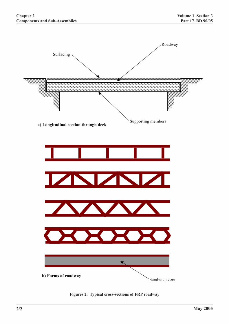
Roadway. The part of the bridge deck formingthe carriageway and transferring wheel loads tothe supporting members. It is assumed that theroadway would consist of top and bottomflanges, separated by a core of FRP webs or afiller material; Figure 2 shows some typicalexamples;
Supporting members. The remaining part of thebridge deck, consisting of the main structuralmembers (usually longitudinal beams) thatsupport the roadway and transfer loads to piers orabutments. Note: the supporting members may beFRP, steel, concrete, or a combination of these;
1/1
Volume 1 Section 3Part 17 BD 90/05
Chapter 1Introduction
c) Connections between the roadway andsupporting members;
d) Surfacing system. The surface course, includingwaterproofing if required, and anti-skid runningsurface;
e) Joints. Structural joints between sections ofroadway or supporting members;
f) Parapet anchorage. Requirements for bridgeparapets are given elsewhere: only the anchorageis covered in this standard;
g) Ancillaries: kerbs, footways, drainage, serviceducts, anchorage of street furniture (lightingcolumns, signs, etc).
Roles and Responsibilities
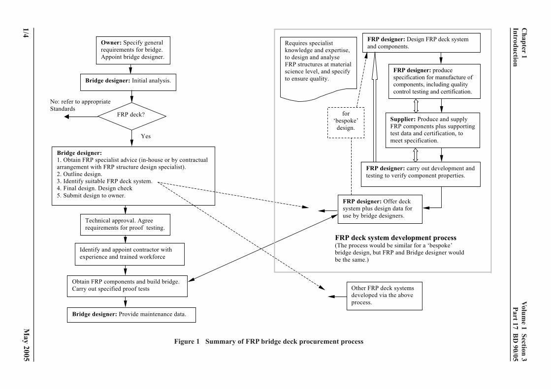
1.8 The design and approval process is summarisedin Figure 1. The process may be divided into:
a) Analysis and design of FRP components atmaterial science level, specification andprocurement;
b) Verification and validation of componentproperties by full-scale tests;
c) Supply of components and supporting designinformation;
d) Design and check of a bridge deck or highwaystructure using components with definedproperties;
e) Technical approval, construction andmaintenance of the structure.
1.9 The roles and responsibilities are separated anddefined so that FRP bridge design is accessible toengineers without specialist expertise. They are asfollows.
The FRP designer is an experienced engineer withspecialist knowledge of FRP materials and designmethods as well as experience relevant to structuraldesign. The FRP designer is responsible to the Bridgedesigner for:
a
b
c
Temedthdfs
TSacs
TthFcbthcThsccc
1bocpwo
1cO
1/2
) Design of FRP components at a material sciencelevel;
) Production of a specification and advice on theprocurement of components from an FRPmanufacturer or supplier;
) Verification of the structural properties of thecomponents in relation to the specification andprovision of design data.
he Bridge designer is an experienced charteredngineer with knowledge of the properties of FRPaterials relevant to structural design but no specialist
xpertise at the material science level. The bridgeesigner may rely on the use of standard components,e properties of which are supplied by the FRP
esigner. The bridge designer has overall responsibilityor the structural adequacy of the bridge or highwaytructure.
he Supplier is usually a specialist FRP producer. Theupplier’s role is to produce components, sub-ssemblies and ancillary items, together with qualityontrol test data and certification to meet thepecifications provided by the FRP designer.
he Contractor is employed to, through liaising withe FRP designer, procure FRP components from anRP manufacturer or supplier and shall assemble FRPomponents and other materials supplied to site and touild the bridge or highway structure, and shallerefore be experienced in assembling FRP
omponents or sub-contract this activity to a specialist.he Contractor’s responsibilities include storage andandling of materials and provision of a methodtatement for all critical processes. In other respects, theontractor’s responsibilities are similar to those for aonventional bridge or highway structure. They shall belearly defined in the contract.
.10 It is anticipated that the FRP design and theridge design shall be carried out by the same companyr Group, or by separate companies with a formalontractual agreement. Whatever arrangement is inlace, the design team shall either include an engineerith sufficient experience of designing FRP structures,r have access to specialist advice.
.11 It shall be necessary to carry out an independentheck (Category II or Category III) of the design. Theverseeing Organisation shall decide what level of
checking is required on a case-by-case basis.
May 2005
Volume 1 Section 3Part 17 BD 90/05
Chapter 1Introduction
1.12 Construction of an FRP bridge deck requiresspecialist expertise and training. Careful attention shallbe paid to the selection of a contractor able todemonstrate (a) relevant experience and (b) a workforcewith appropriate training and skills.
Implementation
1.13 This Standard shall be used for the design of FRPhighway structures and components.
Feedback
1.14 Feedback on the use of this Standard shall beprovided in accordance with HD34, the Implementationand Use of the Standard Improvement System. (DMRB5.3.1)
Abbreviations
1.15 The following abbreviations are used in thisstandard:
BS 5400: Part x means BS 5400: Part x as implementedby the relevant HA standard (BD).
Definitions
Adhesive: A polymeric material capable ofbonding two materials together.
Aramid fibre: A high strength, long-chain,aromatic polyamide synthetic fibre.
Bond: The adhesion of one surface toanother using a high strengthadhesive or other bonding agent.
Carbon fibre: High strength, high modulus fibresproduced from organic materialssuch as rayon, polyacrylonitrile(PAN) or pitch. The term is oftenused interchangeably with“graphite”.
Composite: Or advanced composite. Alternativeterm for FRP, i.e. fibres plus resin toproduce specific performanceproperties.
Fabric: Fibres woven into a fabric. Fibrescan be aligned in any direction, with0°, 45° and 90° being the mostcommon.
May 2005
FRP: Fibre reinforced polymer comprisinghigh strength fibres in a resinmatrix.
FRP properties: Properties of the completed laminateor structural section, or part sectionsuch as web or flange.
Glass fibre: A fibre spun from an inorganicproduct of fusion that has cooled toa rigid condition withoutcrystallising.
Hand layup: A process in which resin andreinforcement are applied manuallyeither to a mould or to a workingsurface in a number of successivelayers.
Laminate: A composite material consisting ofone or more layers of fibresimpregnated in a resin system andcured.
Prepreg: Fibres, fabrics or mats impregnatedwith resin and attached to a backingpaper or plastic release film in flatform that can be stored for later usein moulds or for hand lay-up.
Pultrusion: A semi-continuous factory methodfor manufacturing FRP laminates ofconstant section in long lengths.Sections currently available includeplates, rods, I, T, angle sections etcand special profiles.
Resin: A polymer which may exist in solid,semi-solid or liquid state. A resinmatrix is used to impregnate thefibres and bind filaments, fibres andlayers of fibre together.
Stress rupture: Also known as creep rupture.Property whereby the material canfail (rupture) at a sustained stresslevel considerably less than theshort-term ultimate stress.
Voids: Air bubbles trapped in the resin orbetween the FRP and parentsubstrate.
Wet layup: A method of installing FRP by hand.The laminates are produced byimpregnating layers of fibres or matsby applying a liquid resin system tothem as they are laid up.
1/3
Volume 1 Section 3
Part 17 BD
90/05
1/4
Chapter 1
Introduction
cess
FRP designer: Design FRP deck system
and components.
Supplier: Produce and supply
FRP components plus supporting
test data and certification, to
meet specification.
FRP designer: produce
specification for manufacture of
components, including quality
control testing and certification.
FRP designer: carry out development and
testing to verify component properties.
designer: Offer deck
em plus design data for
by bridge designers.
eck system development process rocess would be similar for a ‘bespoke’
design, but FRP and Bridge designer would
same.)
ther FRP deck systems
eveloped via the above
rocess.
e’
.
May 2005
Figure 1 Summary of FRP bridge deck procurement pro
Requires specialist
knowledge and expertise,
to design and analyse
FRP structures at material
science level, and specify
to ensure quality.
FRP
syst
use
Owner: Specify general
requirements for bridge.
Appoint bridge designer.
FRP d(The p
bridge
be the
Bridge designer: Initial analysis.
FRP deck?
No: refer to appropriate
Standards
Yes
Bridge designer: 1. Obtain FRP specialist advice (in-house or by contractual
arrangement with FRP structure design specialist).
2. Outline design.
3. Identify suitable FRP deck system.
4. Final design. Design check
5. Submit design to owner.
Technical approval. Agree
requirements for proof testing.
Identify and appoint contractor with
experience and trained workforce
Obtain FRP components and build bridge.
Carry out specified proof tests O
d
p
Bridge designer: Provide maintenance data.
for
‘bespok
design
Volume 1 Section 3Part 17 BD 90/05
Chapter 2Components and Sub-Assemblies
-ASSEMBLIES
2. COMPONENTS AND SUBGeneral
2.1 FRP bridge decks or highway structures coveredby this standard may be made up of closed or opensections bonded and/or bolted together, or by sectionsof deck produced as a single piece. These componentsor sub-assemblies are likely to be transported to site forfinal assembly and erection, so that site joints andancillary components will be required.
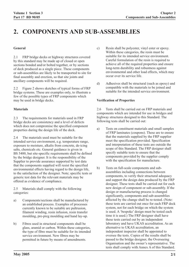
2.2 Figure 2 shows sketches of typical forms of FRPbridge systems. These are examples only, to illustrate afew of the possible types of FRP components whichmay be used in bridge decks.
Materials
2.3 The requirements for materials used in FRPbridge decks are consistency and a level of defectswhich does not compromise the specified componentproperties during the design life of the deck.
2.4 The materials used must be suitable for theintended service environment, e.g. temperature range,exposure to moisture, alkalis from concrete, de-icingsalts, chemicals etc. General guidance is given inBS 5400, but site-specific requirements shall be definedby the bridge designer. It is the responsibility of theSupplier to provide assurance supported by test datathat the components supplied will resist the specifiedenvironmental effects having regard to the design life,to the satisfaction of the designer. Note; specific tests orgeneric test data for the relevant materials may beoffered as evidence of compliance.
2.5 Materials shall comply with the followingcategories:
a) Components/sections shall be manufactured byan established process. Examples of processescurrently known to be suitable are pultrusion,filament winding, resin infusion, resin transfermoulding, pre-preg moulding and hand lay-up.
b) Fibres used in structural components shall beglass, aramid or carbon. Within these categories,the type of fibre must be suitable for its intendedservice environment. New fibres may bepermitted in future by means of amendments.
May 2005
c) Resin shall be polyester, vinyl ester or epoxy.Within these categories, the resin must besuitable for its intended service environment.Careful formulation of the resin is required toachieve all of the required properties and ensurelong-term durability and robustness againstenvironmental and other load effects, which mayoccur over its service life.
d) Adhesives shall be structural (such as epoxy) andcompatible with the materials to be joined andsuitable for the intended service environment.
Verification of Properties
2.6 Tests shall be carried out on FRP materials andcomponents which are intended for use in bridges andhighway structures designed to this Standard. Thefollowing tests shall be carried out:
a) Tests on constituent materials and small samplesof FRP laminates (coupons). These are to ensurethat the materials supplied by the FRP suppliermeet the specification provided. Specificationand interpretation of these tests are outside thescope of this Standard. The FRP designer shallspecify suitable tests to ensure that thecomponents provided by the supplier complywith the specification for manufacture.
b) Tests on full-scale components and sub-assemblies including connections betweencomponents, to verify their structural adequacyand support the design data produced by the FRPdesigner. These tests shall be carried out for eachnew design of component or sub-assembly. If thedesign or manufacturing process is changedsignificantly, components and sub-assembliesaffected by the change shall be re-tested. (Note:these tests are carried out once for each FRP decksystem, not for each bridge on which the systemis used. A ‘bespoke’ design must be tested eachtime it is used.) The FRP designer shall havethese tests carried out by an independentlaboratory and have UKAS accreditation. As analternative to UKAS accreditation, anindependent inspector shall be appointed tooversee the tests. Copies of the results shall bepassed to the bridge designer, the OverseeingOrganisation and the owner’s representative. Thetests shall comply with Annex A of this Standard.
2/1
Volume 1 Section 3Part 17 BD 90/05
Chapter 2Components and Sub-Assemblies
Sandwich coreb) Forms of roadway
a) Longitudinal section through deck
Roadway
Supporting members
Surfacing
Figures 2. Typical cross-sections of FRP roadway
May 20052/2
Volume 1 Section 3Part 17 BD 90/05
Chapter 2Components and Sub-Assemblies
c) Tests on materials, samples and processes (e.g.adhesive bonding) during construction to ensurethe quality of the materials and processes used tobuild the bridge or highway structure. These testsshall be agreed between the bridge designer andFRP designer. They shall be included in thecontract and relevant method statements and besubject to the agreement of the OverseeingOrganisation.
d) Static proof load tests on components or sectionsof deck supplied for a particular bridge. The testsshall consist of a 200 x 200mm patch load placedat a typical ‘worst case’ location on thecomponent. The purpose is to verify the materialand FRP component connection characteristics,and demonstrate that the ‘as-built’ deck has theload capacities and stiffnesses given in the designdata supplied by the FRP designer. The testconditions and the number of tests shall beagreed between the bridge designer and theOverseeing Organisation in consultation with theFRP designer. A minimum of one test per 50m² ofdeck area will generally be required. The first testdeck shall initially be loaded to 1.2 times theserviceability load, with deflection and strainrecorded, then unloaded and re-loaded up tofailure of the deck. Subsequent tests shall becarried out to 1.2 times the serviceability load.
Provision of Design Data
2.7 Design data shall be made available by the FRPdesigner in a form suitable for use by a bridge designerwho is not an FRP specialist. The data shall be ‘designvalues’ which are the lower 95% confidence limit of thetest data. Properties of any connections, anchorages andother ancillary components offered by the FRP designershall be included. The data provided shall include:
a) load capacities, e.g. bending moment and shear,of components for global and local loading;
b) stiffness, e.g. load-deflection curves;
c) reduction in strength and stiffness under longterm loading;
2fprt
2prtB
2rabbsd
2tiTa(u
May 2005
d) fatigue strength for each component or criticaldetail.
.8 Resistance to local loading at locations offeredor such loading by the FRP designer or supplier, e.g.ull-out of bolts, grout plugs, shear keys, etc, andeductions in component properties and limitations onhe placing of holes shall be included.
.9 The temperature range over which the specifiedroperties are achieved shall be stated. The temperatureange shall exceed the full range of serviceemperatures for a UK highway bridge, as specified inD 37 (DMRB 1.3.14).
.10 Durability data, including chemical and UVesistance, uptake of moisture, resistance to freeze/thawnd de-icing salts, mechanical impact of the FRP/resinseing used in the structural member shall be providedy the FRP designer. (Note: Durability data may beupported by specific tests or by previously existing testata).
.11 The bridge designer shall ensure that theemperature and durability data are taken into accountn setting the design values for component properties.he partial factors shall not be relied upon to takeccount of known degradation of material propertiesNote: the partial factors take account of variability andnknown effects).
2/3
Volume 1 Section 3Part 17 BD 90/05
Chapter 3Overview of Design
3. OVERVIEW OF DESIGN
Design Philosophy
3.1 The philosophy to be adopted in the design ofFRP bridge or highway structures and components is asstated in BS 5400: Part 1. The objective is to verifystructural adequacy at the defined ultimate andserviceability limit states. However, the materialcharacteristics of FRP are fundamentally different fromthose of steel or concrete and this needs to be taken intoaccount in the design procedure. This section isintended to give general design advice on the structuraluse of FRP in bridges and how it differs from that of themore traditional construction materials.
3.2 The configuration of the structure and theinteraction between the structural members shall besuch as to ensure a robust and stable design. Thestructure shall be designed to support loads caused bynormal function, but there should be a reasonableprobability that it will not collapse or sufferdisproportionate damage under the effects of misuse oraccident (Clause 3.4 of BS 5400: Part 1).
3.3 In general, currently available FRP materials andcomponents used for bridge decks or highwaystructures have high strength and low stiffnesscompared to steel. Therefore design may be governedby deflection rather than stress and by Serviceabilityrather than Ultimate limit states, to a greater extent thanfor conventional designs.
3.4 The ratio of maximum design stress to ultimatestress will be smaller for FRP than for steel. Forexample BS 5400: Part 4 places a Serviceability limit of0.75fy on steel reinforcement for dead load and/or liveload stresses. The limit on FRP is lower for severalreasons:
a) FRP materials are brittle in the sense of beinglinear elastic to failure: this does not necessarilymean that the structure will fail in a brittlemanner but it does suggest that re-distribution ofload may not occur to the same extent as in steeland reinforced or pre-stressed concretestructures. However, cracking and excessive localdeformations may occur before failure and somelimited load capacity may remain after failure.
b) Creep and/or stress rupture reduce the capacity ofsome fibres and resins under long-term sustainedload.
c)
It shpropstiffn
3.5comdesigdetailongdamnecebehato fa
Mat
3.6diffeconsthe baffec
a)
b)
c)
d)
May 2005
FRP materials are relatively new in the serviceenvironment found on highway bridges, so thereis greater uncertainty over their long-termbehaviour.
all be necessary to reduce the mechanicalerties by gamma (material) factors for strength andess, which are given in section 4.5.
If the FRP roadway is designed to actpositely with the supporting members then thener must ensure through appropriate analysis andling that the connections provide sufficientitudinal shear strength without causing localage to the FRP components. It shall also bessary to provide data to show the long-termviour of the connections are not compromised duetigue or environmental loading.
erial Characteristics
The bridge designer should be aware of therences between FRP and other, more familiar,truction materials. Some of these differences affectehaviour of the finished structure, while otherst construction. The main differences are:
Light weight, permitting different handling,assembly and transport methods.
FRP materials are generally linear elastic up tofailure and do not behave in a ductile manner,like steel. Non-linear analysis methods such asyield-line and moment re-distribution shall not beused.
The properties of FRP materials depend on thedirection being considered and are a function ofthe amount and strength of fibres in thatdirection. Those which are mainly uni-directionalwill have very low transverse properties.
The effect of local stress concentrations isdifferent from that in steel and concrete due tothe lower ductility of FRP. Hence, the effect ofattachments, joints, holes, etc, will be different.The bridge designer should consider these effectsin relation to the applied loading.
3/1
Volume 1 Section 3Part 17 BD 90/05
Chapter 3Overview of Design
Modulus (%) at (kg/m3)(GPa) Failure
220 - 240 1.6 - 2.0 1740 - 2200
300 - 350 0.9 - 1.14 1740 - 2200
540 - 640 0.39 - 0.4 1740 - 2200
70 - 80 5.0 - 5.1 1390 - 1470
115 -130 3.0 - 3.1 1390 - 1470
70 2.9 - 4.3 2460 - 2580
85 - 90 4.1 - 5.3 2460 - 2580
Elastic Elongation DensityModulus (%) at (kg/m3)
(GPa) Failure
3.1 - 4.6 1.6 - 2.5 1110 - 1250
2.6 - 3.8 1.5 - 8.0 1110 - 1200
3.0 - 4.0 1.0 - 1.8 1000 - 1250
Elastic Elongation DensityModulus (%) at (kg/m3)
(GPa) Failure
150 1.6 - 2.0 1600
40 5.0 - 5.1 1400
70 3.0 - 3.1 1400
40 2.9 - 4.3 1800
e) Special attention shall be paid to the design ofbearings, movement joints, parapets, kerbs, signsand lighting, provision for services, etc. in orderto limit local stress concentrations.
f) Special attention shall be paid to loads that donot act in the principal fibre directions of thematerial.
g) The lower modulus of some FRP materialscompared to steel results in larger displacementsand dynamic effects. In addition, bucklingcapacity is more likely to be critical than in steelstructures.
h)
i)
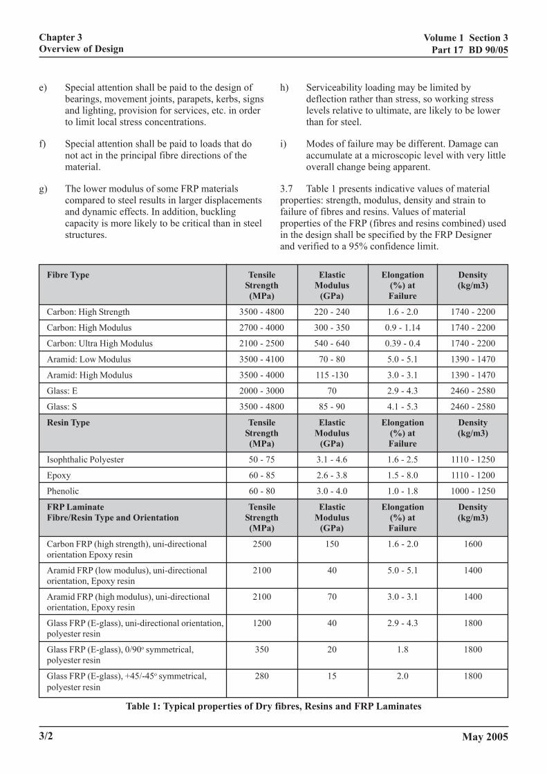
3.7propefailurpropein theand v
Fibre Type TensileStrength(MPa)
Carbon: High Strength 3500 - 4800
Carbon: High Modulus 2700 - 4000
Carbon: Ultra High Modulus 2100 - 2500
Aramid: Low Modulus 3500 - 4100
Aramid: High Modulus 3500 - 4000
Glass: E 2000 - 3000
Glass: S 3500 - 4800
Resin Type TensileStrength(MPa)
Isophthalic Polyester 50 - 75
Epoxy 60 - 85
Phenolic 60 - 80
FRP Laminate TensileFibre/Resin Type and Orientation Strength
(MPa)
Carbon FRP (high strength), uni-directional 2500orientation Epoxy resin
Aramid FRP (low modulus), uni-directional 2100orientation, Epoxy resin
Aramid FRP (high modulus), uni-directional 2100orientation, Epoxy resin
Glass FRP (E-glass), uni-directional orientation, 1200polyester resin
o
3/2
Glass FRP (E-glass), 0/90 symmetrical, 350polyester resin
Glass FRP (E-glass), +45/-45o symmetrical, 280polyester resin
Table 1: Typical properties of Dry
Serviceability loading may be limited bydeflection rather than stress, so working stresslevels relative to ultimate, are likely to be lowerthan for steel.
Modes of failure may be different. Damage canaccumulate at a microscopic level with very littleoverall change being apparent.
Table 1 presents indicative values of materialrties: strength, modulus, density and strain toe of fibres and resins. Values of materialrties of the FRP (fibres and resins combined) used design shall be specified by the FRP Designererified to a 95% confidence limit.
Elastic Elongation Density
May 2005
20 1.8 1800
15 2.0 1800
fibres, Resins and FRP Laminates
Volume 1 Section 3Part 17 BD 90/05
Chapter 3Overview of Design
3.8 In general, a stress limit approach to design shallbe adequate in most cases, but a more sophisticatedapproach is also permitted. High local stresses mayoccur at specific locations, eg. under wheel loads andclose to bearings, so testing is considered necessary.The tests are intended to cover both global and localwheel loading.
Analysis
3.9 Conventional methods of linear elastic analysismay be used assuming plane sections remain plane. Noredistribution is permitted.
3.10 BS 5400: Part 1 states the general principles to beadopted in the calculation of load effects and memberresistance and these should be followed for FRP bridgesand components. However the use of plastic methods ofanalysis is not permitted.
3.11 The effect of local stress concentrations needscareful consideration, e.g. at connections and adjacentto bearings. The bridge designer shall seek specialistadvice from the FRP designer in this area.
May 2005 3/3
Volume 1 Section 3Part 17 BD 90/05
Chapter 4Design Requirements
4. DESIGN REQUIREMENTS
4.1 This section relates to the design of a bridgeusing FRP components, carried out by the Bridgedesigner. Design of FRP components is outside thescope of this Standard.
Loading
4.2 The design loading to be used for FRP bridgesfor serviceability and ultimate limit states are as givenin BD 37 (DMRB 1.3.14).
Design Life
4.3 The design life of an FRP deck shall normally be120 years as given in BS 5400: Part 1, Section 6 (andelsewhere). The provisions of that section regardinginspection, repair and maintenance shall be taken intoaccount in the design.
4.4 A shorter design life may be permitted where it isotherwise desirable to use a material which is so newlydeveloped that it is not possible to provide reliableevidence for a life of 120 years and where the followingconditions are met:
a) The main structural members shall have a designlife of 120 years;
b) Where FRP main beams are used, higher materialfactors for ULS and SLS shall be used as given inTables 2 and 3. Provision shall also be made forinspection and rapid replacement without unduedisruption to users, should the design life not beachieved;
c) Other parts have a life of at least 30 years andprovision is made for inspection and rapidreplacement without undue disruption to users;
d) Failure of a single affected part or componentdoes not endanger the stability of the structure;
e) A design life of less than 120 years may bejustified under the provisions of BS 5400 or otherStandard, for example for re-decking an existingbridge or highway structure.
U
4.stTthstoftein
Se
4.limB
D
4.devaoritslimlodebo
4.stth25th4.
V
4.“ldisuoutoinbr
May 2005
ltimate Limit States
5 The general requirements for the ultimate limitates are as specified in BS 5400: Part 1, Clause 3.2.he design should be carried out using data supplied bye FRP designer for appropriate values of ultimaterength and/or strain limits. These should take account creep, sustained load, deterioration, ageing,mperature effects and any other effect that mightfluence the strength and stiffness.
rviceability Limit States
6 The general requirements for the serviceabilityit states to be considered are as specified in
S 5400: Part 1, Clause 3.2.
eflection
7 Serviceability requirements may govern thesign of FRP components due to the relatively lowlue of elastic modulus. The deflection of the structure any part of it shall not be such as to adversely affect appearance or serviceability. This can be achieved byiting the deflection of FRP components under live
ad to span/300, including shear deformation. Theflection limit shall be applied locally and globally, inth longitudinal and transverse directions.
8 Where the FRP components are supported oneel or concrete main beams, the global deflection ofe main beams under live load shall be limited to span/0. The global and local deflection under live load ofe FRP components shall be limited to span/300 as per7 above.
ibration
9 The lightweight nature of FRP may result in aively” bridge. Excessive vibrations may cause userscomfort and affect the bond in joints and betweenrfacing and FRP. Dynamic analysis shall be carriedt to determine the natural frequencies of the structure indicate the susceptibility of the bridge to trafficduced vibrations. Experience with conventionalidges suggests that if the fundamental natural
frequency is above 5Hz, then dynamic effects are notsignificant.
4/1
Volume 1 Section 3Part 17 BD 90/05
Chapter 4Design Requirements
4.10 Vibrations due to wind shall be considered inaccordance with BD 49 (DMRB 1.3.3).
4.11 For footbridges and the structural components ofbridges whose prime function is to carry pedestrianloading, the requirements of BD 37 (DMRB 1.3.14),Appendix B shall be applied.
Fatigue Limit State
4.12 This Standard covers fatigue due to trafficloading. If other effects such as wind loading orvibration are significant, they shall be taken intoaccount in the fatigue assessment.
4.13 As far as possible, details which introduce stressconcentrations, such as bolted or bonded attachmentsshould be located where they are not subject to dynamicloading. Where such details are subjected to dynamicloading they shall be included in the fatigue check. TheFRP designer shall provide data for any ‘standarddetails’ offered by him for use in areas subject todynamic loading.
4.14 Unless otherwise agreed with the OverseeingOrganisation, design traffic loading for fatigue shall betaken from BS 5400 Part 10, table 11. A single wheelmay be represented by a uniformly distributed load on asquare contact area 200mm x 200mm. Note. The fatiguechecks required by this Standard are based on alldynamic loads being lower than the fatigue damagethreshold, so the number of vehicles is not relevant.
4.15 Consideration shall be given to the risk of highlocal dynamic stresses at locations remote from wheelloads, e.g. in an FRP section close to a bearing. Thesestresses may arise from secondary effects such as out ofplane bending, or unintended restraint.
4.16 A full fatigue assessment is outside the scope ofthis Standard. Checks shall be carried out for thefollowing:
a) Local effects. Wheel loads on the roadwayaffecting details such as webs, flanges, web-flange connections, plus joints betweencomponents or sections of deck.
b) Global effects. Bending moment and shearforces on components and joints in the roadwayand supporting decks due to wheels, axles or
4.1decthe5Ache
4.1as
Fa
4.1
locloa
wh
Fa
4.2
4.2and
4/2
groups of axles.
7 Where a bridge or highway structure with an FRPk is designed for less than 45 units of HB loading, axle loads of vehicle types 18GT, 9TT, 7GT, 7A and-H may be reduced as follows for the global effectsck:
For 37.5 units HB divide axle weight by 1.3.
For 25 units HB divide axle weight by 1.7.
8 The partial factor for fatigue, γfatm shall be taken1.0.
tigue check (i) local effects
9 The requirements of this Standard will be met if:
al wheel load capacity, Wfatm.γfatm ≥ design wheeld, Wfatd.γfatd
ere Wfatm is the wheel load corresponding to aconstant amplitude endurance of 107 cycles(L0) on the design S-N curve. The value ofWfatm shall be provided by the FRP designeron the basis of tests, see annex A.
For bridges designed to BS 5400, Wfatd isequal to 30kN, and γfatd is equal to 1.5.
(Note. the highest single wheel load inBS 5400 Part 10 Table 11 for vehicles<40t GVW is 30kN. A factor of 1.5 is appliedto allow for the combined effect of twinwheels and for wheel loads >30kN due tovehicle types 5A-H to 18GT-H.)
tigue check (ii) global effects
0 The requirements of this Standard will be met if:
Bending moment fatigue capacity, BMfatm.γfatm ≥Maximum bending moment due to dynamicloading, BMfatd.γfatd
and
Shear force fatigue capacity, SFfatm.γfatm ≥Maximum shear force due to dynamic loading,SFfatd.γfatd
1 Values of BMfatm and SFfatm for each component joint between components shall be provided by the
FRP designer on the basis of tests, see Annex A.
May 2005
Volume 1 Section 3Part 17 BD 90/05
FRP main beams
anent Transient Permanent
3.0 3.0 4.5
3.0 3.0 4.5
2.0 2.5 4.5
tors to be applied at ULS
FRP main beams
anent Transient Permanent
1.5 1.8 2.5
1.5 1.8 2.5
.25 1.5 2.3
tors to be applied at SLS
Chapter 4Design Requirements
Partial Safety Factors for Load
4.22 The partial safety factors for load shall be takenfrom BD 37/01.
Partial Safety Factors for Material
Ultimate Limit States
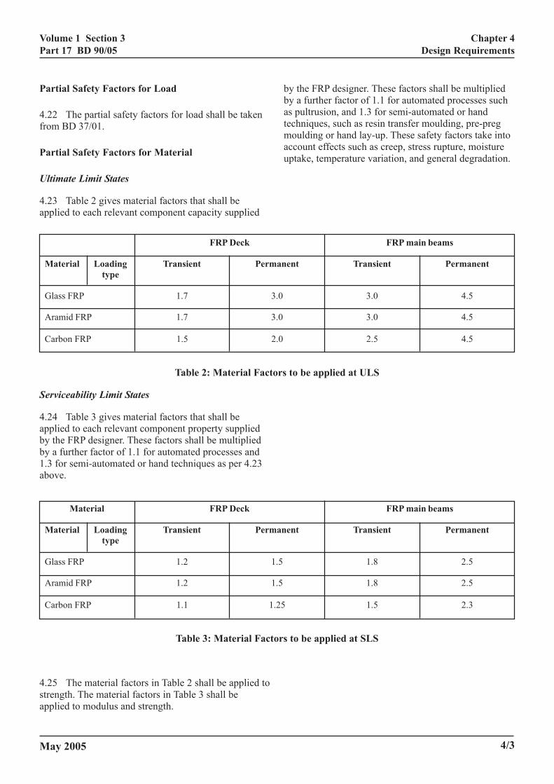
4.23 Table 2 gives material factors that shall beapplied to each relevant component capacity supplied
FRP Deck
Material Loading Transient Permtype
Glass FRP 1.7
Aramid FRP 1.7
Carbon FRP 1.5
Table 2: Material Fac
Serviceability Limit States
4.24 Table 3 gives material factors that shall beapplied to each relevant component property suppliedby the FRP designer. These factors shall be multipliedby a further factor of 1.1 for automated processes and1.3 for semi-automated or hand techniques as per 4.23above.
Material FRP Deck
Material Loading Transient Permtype
Glass FRP 1.2
Aramid FRP 1.2
Carbon FRP 1.1 1
Table 3: Material Fac
4.25 The material factors in Table 2 shall be applied tostrength. The material factors in Table 3 shall beapplied to modulus and strength.
May 2005
by the FRP designer. These factors shall be multipliedby a further factor of 1.1 for automated processes suchas pultrusion, and 1.3 for semi-automated or handtechniques, such as resin transfer moulding, pre-pregmoulding or hand lay-up. These safety factors take intoaccount effects such as creep, stress rupture, moistureuptake, temperature variation, and general degradation.
4/3
Volume 1 Section 3Part 17 BD 90/05
TS
Chapter 5General Requirements
5. GENERAL REQUIREMEN
Durability
Service Environment
5.1 The resistance of the FRP material to theexpected extreme in-service environmental conditionsshall be verified by appropriate testing and/or back-updata. This includes resistance to water, alkalis,chlorides, ultra-violet light, chemicals (vehicle oil andfuel) and de-icing salts.
Resistance to Impact Damage
5.2 FRP can be susceptible to impact damage fromvehicle accidents or falling loads. The FRP designershall provide information on the resistance of therelevant FRP components to impact damage. StructuralFRP components shall have a minimum headroomabove the carriageway of 5.5m.
Detailing
5.3 Proper detailing of connections is one of the mostimportant aspects in ensuring the long-termperformance of any FRP bridge structure. Mostconnections shall be either bonded, bolted or acombination of both. It is therefore critical that thesedetails are carefully worked up and designed to ensurethat they do not compromise the integrity of the overallstructure. In particular careful consideration shall begiven to protection of the end of the FRP units,levelling of main beams for effective connectionbetween main beams and roadway units, deck endconnections, parapet connections and application of therunning surface.
5.4 Where bolted connections are used, the effect ofhigh stress concentrations should be considered. Pleaserefer to Clauses 2.7 and 2.8.
Surfacing
5.5 The surfacing shall be considered part of the FRPdeck system. The FRP designer may offer a surfacingsystem as part of an FRP deck. In this case, test datashall be provided to demonstrate the durability of thesurfacing.
5.ofspshtode
5.cobr
5.noinmmshne
5.sudefa
5.betegrco
5.berem
5.enpa
5.is no
Pa
5.vem
May 2005
6 Care is needed to select materials which fulfil all the service conditions. If the surfacing is to beecified by the Bridge designer, particular attentionall be given to the requirements listed in Clauses 5.7 5.13 below, and tests carried out where necessary tomonstrate the durability of the materials selected.
7 The surface shall provide skid resistancempatible with the pavement on either side of theidge.
8 Although a conventional waterproofing layer ist required to protect the deck, the design shallcorporate adequate drainage to avoid excessiveoisture take-up. The effects of differential thermalovement between surface course and FRP roadwayall be considered and a ‘buffer’ layer provided ifcessary.
9 The designer shall ensure that strains in therface course due to wheel loading and resulting localflection of the roadway are not so high as to causetigue failure of the surfacing material.
10 The bond between roadway and surfacing shall sufficient to prevent failure of the bond in service. Ansile bond strength ≥1N/mm² and a shear strengtheater than the shear strength of the surfacing shall bensidered sufficient.
11 Provision shall be made for the surface course to replaced at the end of its life. A method statement forplacement shall be included in the maintenanceanual. (See also Clause 6.6)
12 The method of installation shall be such as tosure a smooth transition between deck and adjacentvement.
13 The temperature at which the surfacing materiallaid shall be considered to ensure that the roadway ist adversely affected.
rapets
14 Vehicle parapets and combined pedestrian/hicle parapets (referred to below as parapets) musteet the requirements of the Interim Requirements for
Road Restraint Systems (IRRRS) and BS EN 1317Parts 1 & 2. Careful consideration must be given to the
5/1
Volume 1 Section 3Part 17 BD 90/05
Chapter 5General Requirements
way in which forces from the parapet are transferred tothe bridge and its supports
5.15 Where an FRP deck is to be installed ontoexisting steel or concrete beams, parapets may beattached directly to the beams subject to the agreementof the Overseeing Organisation, and provided that thebeams have been assessed as capable of carrying theadditional loads resulting from attaching the parapets.
Movement Joints
5.16 Depending on the properties of the materialsused, conventional movement joints may not berequired at the ends of the deck. However, a gap will bepresent between deck ends and abutments and someform of movement joint is necessary.
5.17 The movement joints shall:
a) prevent leakage between deck end and abutment;
b) provide a smooth running surface over the gapand allow the level of the surface course adjacentto the deck and on the deck to be set equal, sothat dynamic magnification of wheel loading isminimised.
5.18 The continuity requirements of BD 57 (DMRB1.3.7) can be relaxed provided that extra precautionsare taken at the joint. These precautions may includeextra rebar cover, drainage falls, coating of the rebar oruse of stainless steel or FRP rebar, coating of theconcrete in the vicinity of the movement joint, etc.
Resistance to Fire
5.19 There are currently no requirements for fireresistance of bridges in BS 5400. FRP structures poseno particular threat over and above that to be found intraditional bridges. However, the use of fire retardantadditives in the resin shall be considered for criticalstructural components whose loss would result indisproportionate effects. Neither the fibre reinforcementnor the fillers currently used in the resin supportcombustion.
5.20 The high fibre content of structural componentslikely to be used in bridge and highway structureapplications offer good fire resistance. Componentswith long unidirectional fibres maintain strength muchlonger than chopped fibres. Because of the low thermalconductivity of FRP, fire damage if it occurs is likely tobe localised.
5/2
Surface Finish
5.21 Care shall be taken to ensure that the colour andtexture of visible FRP surfaces are consistent.
May 2005
Volume 1 Section 3Part 17 BD 90/05
AINTENANCE
Chapter 6Construction and Maintenance
6. CONSTRUCTION AND M
6.1 Construction of an FRP deck shall be carried outby a suitable specialist contractor employing operativestrained in the techniques to be used. Special attentionshall be paid to the provision of method statements, to aprogramme of inspection at each stage of theconstruction process and to provision of suppliers’certificates and samples for quality control testing.
6.2 FRP components can be less robust thantraditional materials and may be damaged by carelesshandling. It is therefore important to select a contractorable to specify and adhere to procedures for lifting,storage, transportation and installation.
6.3 It is a requirement that a covered area withappropriate environmental control, ie temperature,humidity, etc be set up for the assembly of FRPcomponents into sections of deck or a complete deck,where site bonding is required.
6.4 The following information shall be provided bythe FRP designer to aid construction, maintenance andrepair:
a) requirements for transportation, handling andstorage. These should be sufficient to preventdamage and deterioration of properties;
b) guidance on methods of cutting and drilling,including protective treatment to cut surfaces;
c) method of repairing local damage duringconstruction and criteria for assessing thestructural adequacy of damaged parts;
d) guidance on assembly methods which willproduce a structure in which the specifiedproperties will be achieved;
e) data to enable repairs to be carried out to FRPcomponents during the life of the bridge,including sufficient details of the materials toenable compatible repair materials to beindependently sourced;
f) sufficient data to enable a replacement surfacingsystem to be specified and independentlysourced, including details of the system installedat the time of construction, plus chemical andmechanical characteristics of the FRP material atthe surface of the deck;
May 2005
g) guidance on inspection and the significance ofdefects.
6.5 Manufacturers’ advice shall be sought in relationto the safe storage of adhesives on site, and otherassociated items such as surface primers.
6.6 The bridge designer shall provide sufficientinformation and data to the bridge owner or his agent toenable the bridge to be maintained in a serviceablecondition throughout its design life. The informationshall be sufficient to allow materials for repair andreplacement to be sourced independently of the FRPdesigner or supplier of the deck. The informationprovided shall include method statements and material/loading data for the following:
a) removal of the surfacing system;
b) installation of a replacement surfacing system;
c) replacement of a section of the roadway;
d) replacement of movement joints;
e) replacement of bearings;
f) reinstatement of a parapet following vehicleimpact (where standard anchorage details areoffered by the FRP designer or supplier);
g) de-commissioning and recycling.
6.7 The bridge designer shall provide Health andSafety data sheets detailing precautions to be takenwhen handling and working FRP materials includingdetails for safe disposal of FRP and adhesives.
6/1
Volume 1 Section 3Part 17 BD 90/05
May 2005
Chapter 7References
7/1
7. REFERENCES
7.1 Design Manual For Roads and Bridges
HD 34 Implementation and Use of the StandardsImprovement System (DMRB 5.3.1)
IAN 44/02 (Rev1) Introducing Interim Requirementsfor Road Restraint Systems (IRRRS)
BD 37 Loads for Highway Bridges (DMRB 1.3.14)
BD 49 Design Rules for Aerodynamic Effects onBridges (DMRB 1.3.3)
BD 57 Design for Durability (DMRB 1.3.7)
7.2 BSI Publications
BS5400: Part 1 Code of Practice for Steel, Concrete andComposite Bridges. General Statement
BS EN 1317-1-1998 Road Restraint Systems:Terminology and General Criteria for Test Methods
BS EN 1317-2-1998 Road Restraint Systems: ImpactTests acceptance and tests methods for safety barriers
7.3 Other Publications
The following background information will be ofassistance to designers:
Clarke, J L (1996). Structural design of polymercomposites. EUROCOMP Design code and handbook.The European Structural Polymeric Composites Group,edited by J L Clarke, E and FN Spon, London.
Cripps, A (2002). Fibre-reinforced polymer compositesin construction. CIRIA C564, Construction IndustryResearch and Information Centre, Department of Tradeand Industry.
Hollaway, L C and P R Head (2001). Advanced polymercomposites and polymers in the civil infrastructure.Elsevier Science, London.
Hutchinson, A R (1997) CIRIA Project Report 46,Joining of fibre-reinforced polymer compositematerials, CIRIA, UK.
CIRIA (2000), The use of FRP in construction, CIRIA,UK.
Volume 1 Section 3Part 17 BD 90/05
May 2005 8/1
8. ENQUIRIES
All technical enquiries or comments on this Standard should be sent in writing as appropriate to:
Chief Highway EngineerThe Highways Agency123 Buckingham Palace RoadLondon G CLARKESW1W 9HA Chief Highway Engineer
Chief Road EngineerScottish ExecutiveVictoria QuayEdinburgh J HOWISONEH6 6QQ Chief Road Engineer
Chief Highway EngineerTransport WalesWelsh Assembly GovernmentCathays Parks M J A PARKERCardiff Chief Highway EngineerCF10 3NQ Transport Wales
Director of EngineeringThe Department for Regional DevelopmentRoads ServiceClarence Court10-18 Adelaide Street G W ALLISTERBelfast BT2 8GB Director of Engineering
Chapter 8Enquiries
Volume 1 Section 3Part 17 BD 90/05
OF DESIGN PROPERTIES
Annex AVerification of Design Properties
ANNEX A VERIFICATION
A. Verification of Properties for Roadway Panels
1. The properties provided by the FRP designershall be supported by experimental evidence.
2. Production of components and sub-assembliesshall be carried out to a quality assurance plan approvedby the FRP designer and which includes sampling andtesting to appropriate Standards.
3. The FRP designer shall ensure that the contractorcarries out static tests on completed components or sub-assemblies. Connections between components shall beincluded in the tests. Test configurations and loadsapplied shall be generally similar to highway bridgedeck loading. A sufficient number of each test shall becarried out to enable the characteristic (95%) value tobe determined. Tests shall be carried out to confirm thestrength and modulus of the components. The majorityof tests shall be carried out to the serviceability loadmultiplied by a factor of 1.2. The tests shall be for atleast one simply supported condition and one 2-spancontinuous support condition. At least one test shall becarried out to failure per support condition, after havingbeen loaded to 1.2 times the serviceability load.
4. Where a recommended design for attachments,e.g. of FRP deck components to supporting members,parapets or street furniture, is provided by the FRPdesigner, the design shall be verified by testing and/ordata provided by the supplier. Alternatively, the bridgedesigner may design attachments and have themverified by testing.
B. Test Requirements for Static and FatigueLoads
1. Tests shall be carried out by the FRP designer toverify the static and fatigue strength of the deck. Thesetests are required for each new deck system (or‘bespoke’ bridge design) and following significantmodifications to an existing system. The tests shallinclude:
(a) all potential fatigue failure locations;
(b) all joints and connections;
(c) any proposed method of repair, or replacement ofcomponents provided by the FRP designer.
May 2005
2. The tests shall be submitted to the OverseeingOrganisation for approval.
3. The tests shall be carried out on full-scalesections of the component taken from a normalproduction batch.
Local Effects
4. Identify all potential failure locations anddetermine the position of a single wheel, which willproduce the most severe effect at each location, i.e. thepositions corresponding to the peak and trough valuesof an influence line for strain, due to the passage of asingle wheel.
5. The test is to reproduce the effect of a singlewheel passing over the potential failure location. Thewheel load may be represented by a steel loading pad200mm x 200mm square faced with ≥6mm thick rubber.For some locations the most severe effect will beproduced by two adjacent pads loading alternately, e.g.if the passage of a wheel produces both tensile andcompressive strains. Where possible, several locationsmay be covered by one load position. The fatigue testload shall be set to the required value of local wheelload capacity, Wfatm.
Global Effects
6. The component to be tested shall be supported ina manner that is similar to its intended servicecondition. The test load shall be applied by a loadingpad designed to minimise local effects, e.g. a 300mm x100mm pad faced with ≥6mm thick rubber. The fatiguetest load shall be set to induce the required designbending moment, BMfatm or shear force, SFfatm.
Test Procedure
7. Carry out five static tests to failure using 200mmx 200mm load pads. The design ultimate static capacityis the characteristic (95%) value of the averagemaximum load, BM or SF achieved.
8. Carry out three fatigue tests. Each test shall berun to failure or 107 cycles. At the end of the fatigue testeach specimen shall be subjected to a static test tofailure under the same conditions as the static tests, seeClause 7.
A/1
Volume 1 Section 3Part 17 BD 90/05
Annex AVerification of Design Properties
9. The result of a fatigue test shall be deemed a‘pass’ if 107 cycles are completed without failure andthe result of the following static test is within twostandard deviations of the mean value of the maximumload, BM or SF achieved in the static tests.
10. If a ‘pass’ result is obtained in all three fatiguetests, the value of the test load, BM or SF may be usedas the design fatigue capacity for the location(s) orcomponent tested.
C. Proof Tests
1. Tests shall be carried out on sections of deck, byan independent laboratory. The purpose of the tests is toverify that the properties used by the Bridge designerare achieved on site, taking into account bothcomponent properties and the methods and materialsused in assembly.
2. The size and number of sections to be tested shallbe determined by the Overseeing Organisation as partof the technical approval, e.g. one test per 50m² of FRPdeck area, in consultation with the bridge designer, theFRP designer and the contractor.
3. The tests shall be specified to enable a directcomparison to be made with the capacities provided bythe FRP designer for strength and modulus.
Where a complete FRP bridge is being assembled (ieFRP main beams and deck), the tests shall include themain structural members, the roadway and theconnections. In other words, a load test on the installedbridge shall be required, in addition to tests on sectionsof the roadway assembled on site.
May 2005A/2