Embed Size (px)
Citation preview

DMVA 100-PS SOLID STATE DUAL DISPLAY/THREE-PHASE DIGITAL VOLTS MONITOR
User's Installation & Operation Manual and
User’s Programming Manual
Revision 1.3 April 19, 2001
Doc # E104-7-06-13
E Electro Industries/GaugeTech
1800 Shames Drive Westbury, New York 11590
Tel: 516-334-0870 u Fax: 516-338-4741 E-mail:[email protected] u www.electroind.com
"The World Leader in Power Monitoring Systems"

D M V A 1 0 0 - P S
Address: Electro Industries/Gaugetech Division of E. I. Electronics, Inc.
1800 Shames Drive Westbury, New York 11590 U. S. A
For Customer or Technical Assistance, Repair and Calibration:
Phone: (516) 334-0870 Fax: (516) 338-4741 E-mail:[email protected] Customer Support & Repair Service
Customer support is available 9:00 A.M. to 4:30 P.M., Eastern Time, Monday through Friday. Please have the model, serial number and a detailed problem description available. If the problem concerns a particular reading, please have all meter readings available. When returning any merchandise to E.I.G., a return authorization number is required. PRODUCT WARRANTY:
Electro Industries/Gaugetech warrants this product to be free from defects in material and workmanship for a period of 1 year from date of shipment. During the warranty period, we will, at our option, either repair or replace any product that proves to be defective. To exercise this warranty, fax or call our customer service department. You will receive prompt assistance and return instructions. Send the instrument, transportation prepaid, to the address above. Repairs will be made and the instrument will be returned.
LIMITATION OF WARRANTY:
This warranty does not apply to defects resulting from unauthorized modification, misuse, or use for any reason other than electrical power monitoring. This unit is not to be used for primary over current protection. Any protection feature in this unit is to be used for alarm or secondary protection only.
This warranty is in lieu of all other warranties, expressed or implied, including any implied warranty of merchantability or fitness for a particular purpose. Electro Industries/Gaugetech shall not be liable for any indirect, special or consequential damages arising from any authorized or unauthorized use of any Electro Industries / Gaugetech product.
STATEMENT OF CALIBRATION:
This instrument has been inspected and tested in accordance with specifications published by Electro Industries/Gaugetech. The accuracy and calibration of this instrument are traceable to the National Bureau of Standards through equipment which is calibrated at planned intervals by comparison to certified standards.
DISCLAIMER:
Information presented in this publication has been carefully checked for reliability; however, no responsibility is assumed for inaccuracies. The information contained in this document is subject to change without notice.
COPYRIGHT:
No part of this manual may be reproduced or transmitted in any form or by any means, electronic or mechanical, including photocopying, recording, or information storage or retrieval systems or any future forms of duplication, for any purpose other than the purchaser's use, without the expressed written permission of Electro Industries/Gaugetech, a division of E.I. Electronics, Inc.
Copyright (C) 2001 Electro Industries/Gaugetech. Division of E. I. Electronics, Inc. All rights reserved. Printed in the United States of America.

D M V A 1 0 0 - P S

TABLE OF CONTENTS
I N S T A L L A T I O N & O P E R A T I O N
CHAPTER 1 MECHANICAL INSTALLATION 1 w Installation of the DMVA 100-PS with K-110 Option for limited
space conditions 1
w Standard Installation of the DMVA 100-PS 1 w Standard Cutout of DMVA 100-PS 2 w Communication Converter
2
CHAPTER 2 ELECTRICAL INSTALLATION 3 Section 2.1 Connecting the Current Circuit 3
2.2 Connecting Voltage Circuit of Potential Transformer 3 2.3 Selecting the Voltage Fuses 3 2.4 Connection to the Main Power Supply 3 2.5 Electrical Connection Installation 4
w 3-Phase, 3-Wire Open Delta Connection 4 w 3-Phase, 4-Wire Wye Connection 4
2.6 Relays and Protection
5
CHAPTER 3 COMMUNICATION INSTALLATION 6 Section 3.1 RS-232C 6
3.2 RS-485 6 3.3 Unicom 2500 9 3.4 Network of Instruments and Long Distance Communication 10
CHAPTER 4 DMVA 100-PS: OVERVIEW 11 Section 4.1 Accessing Max/Min Values 11
4.2 Resetting Values 12 4.3 Accessing the LM1/LM2 Set Limits 13 4.4 Printing Operating Data 14 4.5 Printing Programming Data 14 4.6 Accessing LED Test 15 4.7 Accessing Firmware Versions 16

TABLE OF CONTENTS
P R O G R A M M I N G
CHAPTER 1 GENERAL PROCEDURE OVERVIEW 17 Section 1.1 How to Use This Portion of the Manual 17
1.2 Switch Packs 17 1.3 Programming Mode Entry 18 1.4 Standard Numeric Data Entry
18
CHAPTER 2 ENTERING THE PROGRAMMING MODE 19 Section 2.1 Checksum Error - Protective Mechanism 19
2.2 Password Entry 19
CHAPTER 3 PROGRAMMING GROUP 0: GLOBAL METER SETUP 20 Section 3.1 The Integration Interval 20
3.2 The Meter Address 21 3.3 Communication Baud Rate 22 3.4 System Configuration 23 3.5 Programming Procedure 25
CHAPTER 4 PROGRAMMING GROUP 1 26 Section 4.1 Scale Selections & Full Scale Settings 26
4.2 Full Scale Settings, Volt Channels, Volt Decimal Placement 26
CHAPTER 5 PROGRAMMING GROUP 2: METER CALIBRATION 29 Section 5.1 Standard Calibration 29
5.2 Calibration of Voltage Channels
30
CHAPTER 6 PROGRAMMING GROUP 4: SET LIMITS 32 Section 6.1 Set Limits 32
CHAPTER 7 EXITING THE PROGRAMMING MODE 34
INSTALLATION & OPERATION
CHAPTER 1
MECHANICAL INSTALLATION
1 Electro Industries / GAUGETECH
Doc # E104-7-06-13 DMVA 100-PS Installation & Operation
The following diagrams display the various possible DMVA100-PS mechanical installations and CommunicationConverter installation.
NOTE: ALL MEASUREMENTS ARE IN INCHES.
4.375SQ. .890
2.45
2.425
.336
.714(4) 8-32 SCREWS
4.50SQ.
36" CABLE
.80
3.00
5.00
Electro Industries
MAX/MIN
MINIMUMLIMITS
PHASE
NEXT
PROG
MAX
MIN
LM1 LM2
KVOLTSA B CB C A
VOLTS
A B CB C A
FREQUENCY
PRI
SEC
Diagram 1.1 Installation of the DMVA100 with K-110 Option for limited space conditions.
4.375.890
2.0
SQ.
4.50SQ.
3.0
Electro Industries
MAX/MIN
MINIMUMLIMITS
PHASENEXT
PROG
MAX
MIN
LM1
LM2
KVOLTS
VOLTSA B C C B A
C B A A B C
FREQUENCY
PRI
SEC
Diagram 1.2 Standard Installation of the DMVA100-PS

Chapter 1 Mechanical Installation
2 Electro Industries / GAUGETECH
Doc # E104-7-06-13 DMVA 100-PS Installation & Operation
FIRST PUT (16) PIN
CONNECTOR TOGETHER.
(2) 8-32 SCREWS WILL
SIDE VIEW
0.80
(4) 8-32 SCREWS
LINE UP WITH 2 PEMSON THE BACK PLATE.
0.198 DIA.
3.375
3.375
4.0 DIA.
1.6875
1.6875
RECOMMENDEDCUTOUT
BACK VIEW
Diagram 1.3 Standard cutout for DMVA100-PS.
W Port
Diagram 1.4 Optional Communication Converter or DC Output Module Installation
NOTE: CAREFULLY LINE UP THE GUIDE SCREW AND 8 PIN PORT CONNECTOR TO PREVENT PINS FROM BREAKING

CHAPTER 2
ELECTRICAL INSTALLATION
3 Electro Industries / GAUGETECH
Doc # E104-7-06-13 DMVA 100-PS: Installation & Operation
2.1 CONNECTING THE CURRENT CIRCUIT
The cable used for the current should be installed at 600V AC minimum. The cable connector should be rated at 6 Amps orgreater, and it should have a cross-sectional area of 16 AWG.
The current transformers should be mounted as close as possible to the meter. The following table gives the maximumrecommended distances for various CT sizes, assuming the connection is made via 16 AWG cable.
CT SIZE (VA) MAXIMUM DISTANCE (CT TO DMMS)2.5 VA 10 FEET
5.0 VA 15 FEET
7.5 VA 30 FEET
10.0 VA 40 FEET
15.0 VA 60 FEET
30.0 VA 120 FEET
WARNING: DO NOT LEAVE SECONDARY OF CT WHEN PRIMARY CURRENT IS FLOWING. THIS MAY CAUSE HIGH VOLTAGE WHICH
OVERHEATS THE SECONDARY OF THE CT. IF THE CT IS NOT CONNECTED, PROVIDE A SHORTING BLOCK ON THE SECONDARY OF THE CT.
2.2 CONNECTING VOLTAGE CIRCUIT OF POTENTIAL TRANSFORMER
For proper operation, the voltage connection must be maintained. If an error occurs, such as mistaking Line A for Line B, a PHmessage appears, indicating a Phase Reversal (see Phase Imbalance and Reversal).
The cable required to terminate the voltage sense circuit should have an insulation rating greater than 600V AC and a currentrating greater than 0.1 A.
2.3 SELECTING THE VOLTAGE FUSES
We recommend using fuses, although connection diagrams do not show them. Slow blow, 200 mA rating fuses should be used.
The maximum voltage DMVA100-PS can handle 150V phase to neutral. If Suffix -G is added to the model number, themaximum voltage to be used is 300V phase to neutral.
2.4 CONNECTION TO THE MAIN POWER SUPPLY
The DMVA100-PS requires a separate power supply connection. Listed are the 5 different power supply options andcorresponding.
NOTE: FOR DC-POWERED UNITS POLARITY MUST BE OBSERVED. AN EARTH TO GROUND CONNECTION TO CHASSIS IS MANDATORY FOR
NORMAL OPERATION (TERMINAL 3). DO NOT GROUND THE UNIT THROUGH THE NEGATIVE OF THE DC SUPPLY. SEPARATE GROUNDING IS
REQUIRED.
POWER SUPPLY OPTIONS SUFFIXES CURRENT120V AC NO SUFFIX .1 AAC
240V AC A .05 AAC
24V DC D .5 ADC
48V DC D1 .25 ADC
125V DC D2 .1 ADC

Chapter 2 Electrical Installation
4 Electro Industries / GAUGETECH
Doc # E104-7-06-13 DMVA 100-PS: Installation & Operation
2.5 ELECTRICAL CONNECTION INSTALLATION
Choose the diagram that best suits your application and maintain the polarity. Follow the outlined procedure toverify correct connection.
CONNECTION DIAGRAMS
I. Open Delta PT Connection Three-Phase, Three-Wire Open Delta with and two PTs.(Open Delta System Installation should only be used if the electrical system is a 3-wire OPEN DELTA. Open Deltacan be enabled or disabled in Programming Group 0, Function 3.)
CONTROL +
-
POWER
7
6
5
4
3
2
1
8 9 10 11 12 13
PORT
L1
L
LINEA B C
LOAD
3-PHASE, 3-WIRE OPEN DELTA
BACK VIEW
WITH 2 PTs
II. Three Phase, Four-Wire Wye Connection
7
6
5
4
3
2
1
8 9 10 11 12 13
LINE
N A B C
LOAD
3-PHASE, 4-WIRE WYE
L1
L2POWER
+
-
PORTN.O.N.C.COMN.O.N.C.COM
ALARM 1
ALARM 2
*OPTIONAL RELAY OUTPUT
*
*
BACK VIEW
WITH PT'S

Chapter 2 Electrical Installation
5 Electro Industries / GAUGETECH
Doc # E104-7-06-13 DMVA 100-PS: Installation & Operation
NOTE ON ABOVE DIAGRAMS: SEE PHASE REVERSAL IF A MESSAGE OF PH APPEARS AFTER INSTALLATION.SPECIAL PROGRAMMING IS REQUIRED FOR BOTH CONNECTION DIAGRAMS.
2.6 RELAYS AND PROTECTION
NOTE: THIS SECTION IS APPLICABLE ONLY IF THE -NL RELAY OPTION WAS ORDERED.
The DMVA100-PS's allows the user to access a variety of relay options through the programming mode. The relay optionpackage consists of two relays, which can be dedicated to alarm or communication (or both).
TIME DELAY: Sets off the alarm, alerting the user that an out-of-limits condition occurred during the defined time limit. Thetime delay can be programmed for any desirable duration.
If the relays are dedicated to communication, there are two different modes:
§ Lock ON Relay will not be affected by any alarm condition.§ Lock OFF Relay will not be affected by any alarm condition.
If the relays are used for communication and alarm, there are four different modes:
§ Lock ON Relay stays on regardless of any alarm condition.§ Lock OFF Relay stays off regardless of any alarm condition.§ Free ON Relay turns on unless other conditions force it off.§ Free OFF Relay turns off unless other conditions force it on.
Figure 2.1 - Relay Connection
Close-up of the relays on the rear panel. The relays shown arein the NOT energized state. (Form C relays, rated 250V, 5A, 2each)
20
21
22
23
24
25
N.O.
N.C.
COM
N.O.
N.C.
COM
ALARM #1
ALARM #2
THE INSTRUMENT CAN BE PROGRAMMED TO DETECT TWO ALARM LEVELS FOR THE FOLLOWING FUNCTIONS:
§ LM1/LM2 Voltage AN, BN, CN, AB, BC, CA
§ LM1/LM2 Current A, B, C, N
§ Voltage Imbalance (One level only)
§ Voltage Phase Reversals (One level only)

CHAPTER 3
COMMUNICATION INSTALLATION
6 Electro Industries / GAUGETECH
Doc # E104-7-06-13 DMVA 100-PS: Installation & Operation
3.1 RS-232C
All DMVA100-PS’s can be equipped with: the EIA RS-232C or the EIA RS-485.
RS-232C communication links a single instrument with a computer. Its capability is capable up to 100 feet. Astandard 9-pin female serial port connector mounts on the instrument for direct connection to a computer with a 9-pin cable.
NOTE: ONLY THREE PINS ARE USED IN RS-232C. (See Figure 3.1).
COMMUNICATION
CONVERTER
RS-232 COMMUNICATION CONNECTION
CONNECTION FOR DB-9 FEMALEPIN 2 - RECEIVE OF THE HOST/COMPUTER
PIN 3 - TRANSMIT OF THE HOST/COMPUTER
PIN 5 - GROUND OF THE HOST/COMPUTER
DB-9 CONNECTOR
5 4 3 2 1
9 8 7 6
7
6
5
4
3
2
1
20
21
22
* A DIRECT PIN-TO-PIN CABLE CAN BE USED.
23
24
25
27
26
28
8 9 10 11 12 13
Model SF-232DB
NO NULL-MODEM IS REQUIRED.
Figure 3.1 RS-232C Communication Connection Installation
NOTE: TO AVOID GROUND LOOPS, THE NEUTRAL AND SAFETY GROUND (PIN 3) SHOULD BE CONNECTED TOGETHER AT
ONLY ONE POINT.
3.2 RS-485
NOTE: THIS SECTION APPLIES ONLY IF A COMMUNICATION OPTION WAS ORDERED.
Each DMVA100-PS has an unique address up to four digits long. This allows the user to communicate with up to10,000 instruments. Standard baud rates are available up to 4800 baud. To select the proper baud rate, apply thefollowing rules:
The unit operates up to 4800. For a smaller number of instruments over a long distance, use alower baud. Optimal recommended baud rate is 1200 baud if noisy conditions exist.

Chapter 3 Communication Installation
Electro Industries / GAUGETECH
Doc # E104-7-06-13 DMVA 100-PS Installation & Operation
7
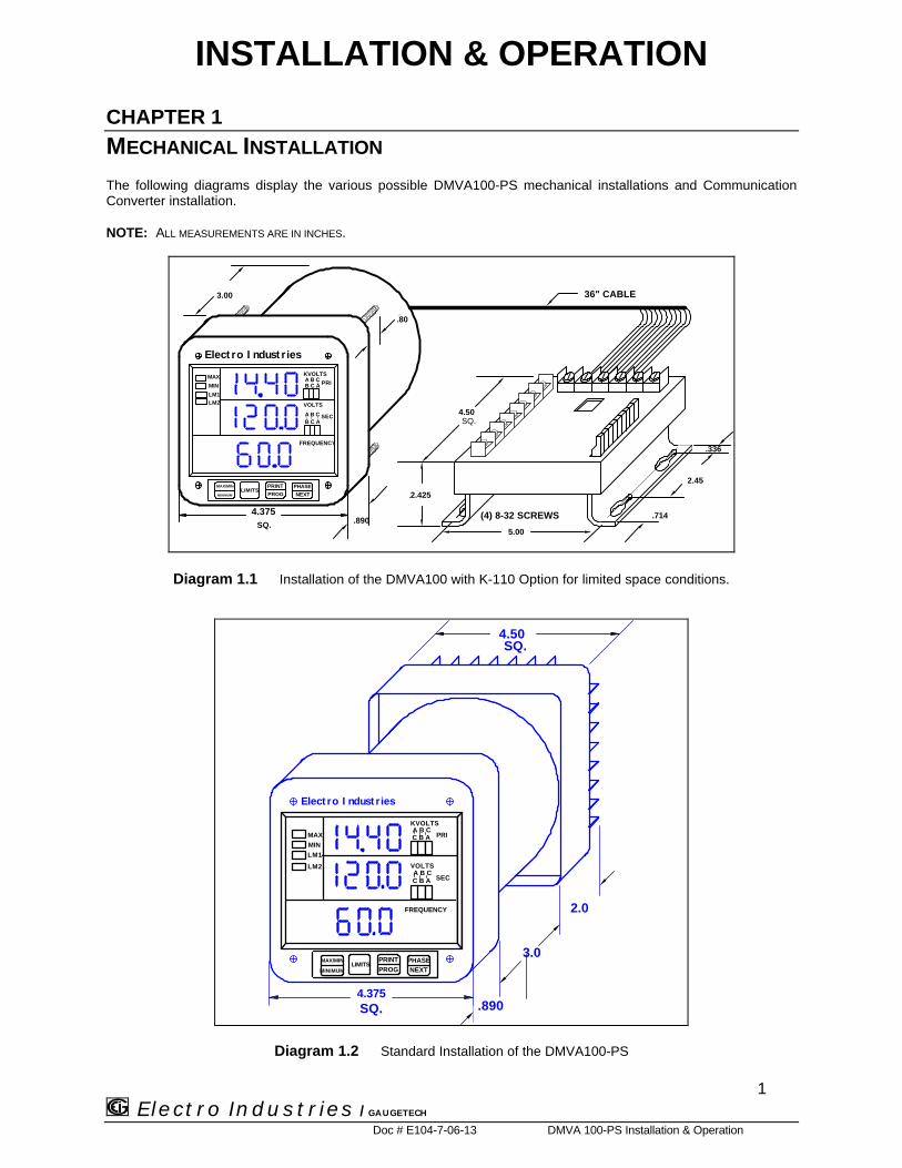
RS-485 is used to parallel multiple instruments on the same link. Its operating capability is up to 4000 feet.• When only 2 wires are used (on the RS-485), the link can include up to 30 instruments, (Figure 3.2).• When using all 4 wires, the link can include up to 60 instruments, (Figure 3.3).
RS-485 Hookup Diagram(2 wire) Half Duplex
Electro IndustriesRS-485 to RS232Communication
Converter
(-)(+)
RS
-232
IBM CompatibleDrawing By: ENGINEERING
Date: August 21, 1997
Electro Industries / GaugeTech
RS
-485
RT
RT
Figure 3.2 2Wire RS-485 Communication Connection Installation Half Duplex
Chapter 3 Communication Installation
Electro Industries / GAUGETECH
Doc # E104-7-06-13 DMVA 100-PS Installation & Operation
8
Drawing By: ENGINEERING
Date: August 21, 1997
Electro Industries / GaugeTech
Electro IndustriesRS-485 to RS232Communication
Converter
RS-2
32RS
-485
RS-485 Hookup Diagram(2 wire) Half Duplex(Closed Loop)
Figure 3.3 2-Wire RS-485 Communication Connection Installation Half Duplex (closed loop)

Chapter 3 Communication Installation
Electro Industries / GAUGETECH
Doc # E104-7-06-13 DMVA 100-PS Installation & Operation
9
RS-485 Hookup Diagram(2 wire) Half Duplex Detail View
Gnd
R+
T+
R-
T-
G R+ T+ R- T- G R+ T+ R- T-
RS-485Communications
Port
Model#SF485DB
RS-485Communications
Port
Model#SF485DB
Electro IndustriesRS-485 to RS232Communication
Converter
RS-
485
Port
Drawing By: ENGINEERING
Date: August 21, 1997
Electro Industries / GaugeTech
RT
Figure 3.4 2-Wire RS-485 Communication Connection Installation Half Duplex Detail View

Chapter 3 Communication Installation
Electro Industries / GAUGETECH
Doc # E104-7-06-13 DMVA 100-PS: Installation & Operation
10
RS-485 Hookup Diagram(4 wire) Full Duplex
Electro IndustriesRS-485 to RS232Communication
Converter
T+ T-R-R+
RS
-232
RS
-485
IBM CompatibleDrawing By: ENGINEERING
Date: August 21, 1997
Electro Industries / GaugeTech
Figure 3.5 4-Wire RS-485 Communication Connection Installation Full Duplex

Chapter 3 Communication Installation
Electro Industries / GAUGETECH
Doc # E104-7-06-13 DMVA 100-PS: Installation & Operation
11
RS-485 Hookup Diagram(4 wire) Full Duplex Detail view
Gnd
R+
T+
R-
T-
G R+ T+ R- T- G R+ T+ R- T-
RS-485Communications
Port
Model#SF485DB
RS-485Communications
Port
Model#SF485DB
Electro IndustriesRS-485 to RS232Communication
Converter
RS-
485
Port
Drawing By: ENGINEERING
Date: August 21, 1997
Electro Industries / GaugeTech
Figure 3.6 4-Wire RS-485 Communication Connection Installation full duplex detail view

Chapter 3 Communication Installation
Electro Industries / GAUGETECH
Doc # E104-7-06-13 DMVA 100-PS: Installation & Operation
12
<==32 UNITS==>
<==32 UNITS==>
32 TRANSPONDER COMPUTER
DEVICE
DEVICE
DEVICE
DEVICE
RS 485TRANSPONDER
RS 485TRANSPONDER
Figure 3.7 2-Wire RS-485 Communication Installation Connection with Transponder
<==32 UNITS==>
<==32 UNITS==>
32 TRANSPONDER COMPUTER
DEVICE
DEVICE
DEVICE
DEVICE
RS 485TRANSPONDER
RS 485TRANSPONDER
Figure 3.8 4-Wire RS-485 Communication Installation Connection with Transponder
3.3 NETWORK OF INSTRUMENTS AND LONG DISTANCE COMMUNICATION
The RS-485 Transponder is required for a large network of instruments.
• In a two-wire connection, a maximum of 900 instruments can be included in the same network, (Figure 3.4).
• Meanwhile, in a four-wire connection, a maximum of 3600 instruments can be included in the same link,(Figure 3.5).
Use modems (dedicated or dial-up) when the instruments are located at great distances. However, set the modemto auto answer at the recommended value of 1200 baud rate if noise conditions exist. Also, flow control must bedisabled.

CHAPTER 4
DMVA 100-PS OVERVIEW
13 Electro Industries / GAUGETECH
Doc# E104-7-06-13 DMVA 100-PS Installation & Operation
The DMVA100-PS measures 10 electrical parameters. Values for each parameter are accessed through the keypad on themeter's front panel (See Figure 4.1).
VOLTAGE PRIMARY AND SECONDARY
A-B
B-C
C-A
B THE PHASE/NEXT BUTTON SELECTS THEPHASE TO BE DISPLAYED.
CA GLOWING ANNUNCIATOR
CURRENTLY DISPLAYED.INDICATES THE PHASE
APRESS LIMITS TO ACCESSPRE PROGRAMMED LIMITS VALUE.
MAXIMUM, MINIMUM,D
PRESS THE
BUTTON TO ACCESSMAX/MIN/LIMITS
KVOLTS
VOLTS
FREQUENCY
MAXMIN
Electro Industries
LM2
LM1
BA
C B
C
A
CBA
MAX/MIN
MINIMUMLIMITS
NEXT
PHASE
PROG
ABC
Figure 4.1The DMVA100-PS front panel with display and keypad
4.1 ACCESSING MAX/MIN VALUES FROM OPERATING MODE
The max/min values represent the highest and lowest average demand over a user programmable time period, know as theINTEGRATION INTERVAL. The readings are calculated using a rolling average technique. Each second, a new reading isused to calculate the max/min and the last reading of the interval is dropped.
ððTo ACCESS MAX/MIN VALUES, follow these steps:
Electro Industries
MAX/MIN
MINIMUMLIMITS
NEXT
PHASEPROGPRINT
KVOLTS
VOLTS
FREQUENCY
MAX
MIN
LM2
LM1
BA
C B
C
A
CBA
ABC
Electro Industries
MAX/MIN
MINIMUMLIMITS
NEXT
PHASEPROGPRINT
KVOLTS
VOLTS
FREQUENCY
MAX
MIN
LM2
LM1
BA
C B
C
A
CBA
ABC
Step 1:a. Press PHASE/ NEXT until thedesired phase is selected.
Step 2:a. Press MAX/MIN/ LIMITS:ððONCE for max of VOLT A-NððTWICE for min of VOLTS A-N

Chapter 4 DMVA 100-PS Overview
Electro Industries / GAUGETECH
Doc# E104-7-06-13 DMVA 100-PS Installation & Operation
14
4.2 RESETTING VALUES FROM OPERATING MODE
Use the reset function if a new value is desired. It is available in two different modes:The standard factory settings is the unprotected mode.
1. UNPROTECTED MODE: allows quick and easy resetting of max/min values.2. PROTECTED MODE: prevents unauthorized personnel from resetting the max/min.3. qq UNPROTECTED RESET
Electro Industries
MAX/MIN
MINIMUMLIMITS
NEXT
PHASEPROGPRINT
KVOLTS
VOLTS
FREQUENCY
MAX
MIN
LM2
LM1
BA
C B
C
A
CBA
ABC
Electro Industries
MAX/MIN
MINIMUMLIMITS
NEXT
PHASEPROGPRINT
KVOLTS
VOLTS
FREQUENCY
MAX
MIN
LM2
LM1
BA
C B
C
A
CBA
ABC
Electro Industries
MAX/MIN
MINIMUMLIMITS
NEXT
PHASEPROGPRINT
KVOLTS
VOLTS
FREQUENCY
MAX
MIN
LM2
LM1
BA
C B
C
A
CBA
ABC
Step 1:a. Press PHASE/ NEXT until thedesired phase is selected.
Step 2:a. Press MAX/MIN/ LIMITS:ððONCE for maxððTWICE for min
Step 3:a. Press PHASE/NEXT to reset.
⇒ The display blanks and a checkmarkappears confirming successful reset.
qq PROTECTED RESET
NOTE: IF THE METER WAS PROGRAMMED TO HAVE A PROTECTED RESET, A PASSWORD MUST BE ENTERED BEFORE ANY READINGS MAY
BE RESET. THE PASSWORD IS 005.
Electro Industries
MAX/MIN
MINIMUMLIMITS
NEXT
PHASEPROGPRINT
KVOLTS
VOLTS
FREQUENCY
MAX
MIN
LM2
LM1
BA
C B
C
A
CBA
ABC
Electro Industries
MAX/MIN
MINIMUMLIMITS
NEXT
PHASEPROGPRINT
KVOLTS
VOLTS
FREQUENCY
MAX
MIN
LM2
LM1
BA
C B
C
A
CBA
ABC
Step 1:a. Press PHASE/NEXT to select the desired phase.
b. Press MAX/MIN/LIMITS:ððONCE for maxððTWICE for min
Step 2:a. Press PHASE/NEXT to commence the Protected reset.
ððThe display blanks, three dashes appear in lower displayand digits begin scrolling in upper display.
ððThe password required is 005.

Chapter 4 DMVA 100-PS Overview
Electro Industries / GAUGETECH
Doc# E104-7-06-13 DMVA 100-PS Installation & Operation
15
Electro Industries
MAX/MIN
MINIMUMLIMITS
NEXT
PHASEPROGPRINT
KVOLTS
VOLTS
FREQUENCY
MAX
MIN
LM2
LM1
BA
C B
C
A
CBA
ABC
Electro Industries
MAX/MIN
MINIMUMLIMITS
NEXT
PHASEPROGPRINT
KVOLTS
VOLTS
FREQUENCY
MAX
MIN
LM2
LM1
BA
C B
C
A
CBA
ABC
Step 3:a. Press PHASE/NEXT twice to enter two zeros and pressagain when the counter reaches the number five.
Step 4:ððUpon entering the correct password, the display blanks anda checkmark appears, confirming successful reset.
4.3 ACCESSING THE LM1/LM2 SET LIMITS FROM OPERATING MODE
The DMVA100-PS is designed with two manual set limits. The set limits monitor the instantaneous readings, warning the userof abnormal conditions. Each limit can detect readings above or below the set level. SET LIMITS: the point when the relaychanges position, if the DMVA100-PS is equipped with the Relay Option (Suffix -NL).
If a limit is exceeded, the annunciator LM1 and/or LM2 indicator glow and the display flashes, alternating between theinstantaneous reading.
ððTo VIEW THE SETUP OF THE LM1/LM2 SET LIMITS OF THE FUNCTIONS, follow these steps:
Electro Industries
MAX/MIN
MINIMUMLIMITS
NEXT
PHASEPROGPRINT
KVOLTS
VOLTS
FREQUENCY
MAX
MIN
LM2
LM1
BA
C B
C
A
CBA
ABC
Electro Industries
MAX/MIN
MINIMUMLIMITS
NEXT
PHASEPROGPRINT
KVOLTS
VOLTS
FREQUENCY
MAX
MIN
LM2
LM1
BA
C B
C
A
CBA
ABC
Electro Industries
MAX/MIN
MINIMUMLIMITS
NEXT
PHASEPROGPRINT
KVOLTS
VOLTS
FREQUENCY
MAX
MIN
LM2
LM1
BA
C B
C
A
CBA
ABC
Step 1:a. To access the set limit, pressLIMITS:ððONE times for LM1ððTWO times for LM2
Step 2:a. Press PHASE/NEXT when the LM1annunciator glows.
ððThe annunciators that glow are out-of-limits in LM1.
Step 3:a. Press PHASE/NEXT when the LM2annunciator glows.
ððThe annunciators that glow are out-of-limits in LM2.
ACCESS MODE
Sections 4.6, 4.7 and 4.8 allow the user to access specific operation tasks (see table below).
ACCESS OPERATION1 Print Operating Data2 Print Programming Data3 Enter Programming Mode (see Programming Section)4 LED Test/ View Firmware Version
NOTE: PRINT COMMANDS 1 AND 2 ARE ONLY AVAILABLE IF ENABLED IN THE PROGRAMMING MODE AND ARE NOT RECOMMENDED
WHEN USING THE MULITMETER CONNECTION RS485.

Chapter 4 DMVA 100-PS Overview
Electro Industries / GAUGETECH
Doc# E104-7-06-13 DMVA 100-PS Installation & Operation
16
4.4 PRINTING OPERATING DATA FROM OPERATING MODE
NOTE: THIS FUNCTION APPLIES ONLY IF A SERIAL PRINTER IS CONNECTED TO THE DMVA 100-PS VIA AN RS232C COMMUNICATION
CONVERTER.
This function sends the data to a serial printer. This allows hard copy of the instantaneous and max/min data of all thefunctions to compile without manually copying the data.
ððTo PRINT THE OPERATING DATA, follow these steps:
Electro Industries
MAX/MIN
MINIMUMLIMITS
NEXT
PHASEPROGPRINT
KVOLTS
VOLTS
FREQUENCY
MAX
MIN
LM2
LM1
BA
C B
C
A
CBA
ABC
Electro Industries
MAX/MIN
MINIMUMLIMITS
NEXT
PHASEPROGPRINT
KVOLTS
VOLTS
FREQUENCY
MAX
MIN
LM2
LM1
BA
C B
C
A
CBA
ABC
Electro Industries
MAX/MIN
MINIMUMLIMITS
NEXT
PHASEPROGPRINT
KVOLTS
VOLTS
FREQUENCY
MAX
MIN
LM2
LM1
BA
C B
C
A
CBA
ABC
Step 1:a. Press PRINT/PROG to begin thespecial printing sequence.
Step 2:a. The display blanks and 1 appears.
b. Press PHASE/NEXT to select.
ðð111 appears confirming a successfulprint command.
4.5 PRINTING PROGRAMMING DATA FROM OPERATING MODE
NOTE: THIS FUNCTION APPLIES ONLY IF A SERIAL PRINTER IS CONNECTED TO THE DMVA 100 VIA AN RS232C COMMUNICATION
CONVERTER.
This function sends the programming data (or the meter setup) to a serial printer for verification and quickreference.
ððTo PRINT THE PROGRAMMING DATA, follow these steps:
Electro Industries
MAX/MIN
MINIMUMLIMITS
NEXT
PHASEPROGPRINT
KVOLTS
VOLTS
FREQUENCY
MAX
MIN
LM2
LM1
BA
C B
C
A
CBA
ABC
Electro Industries
MAX/MIN
MINIMUMLIMITS
NEXT
PHASEPROGPRINT
KVOLTS
VOLTS
FREQUENCY
MAX
MIN
LM2
LM1
BA
C B
C
A
CBA
ABC
Electro Industries
MAX/MIN
MINIMUMLIMITS
NEXT
PHASEPROGPRINT
KVOLTS
VOLTS
FREQUENCY
MAX
MIN
LM2
LM1
BA
C B
C
A
CBA
ABC
Step 1:a. Press PRINT/PROG to enter the ac-cess mode.
Step 2:ððThe display blanks.
a. Press PRINT/PROG until 2 appears.
b. Press PHASE/NEXT to select.
ðð222 appears confirming a successfulprint command.

Chapter 4 DMVA 100-PS Overview
Electro Industries / GAUGETECH
Doc# E104-7-06-13 DMVA 100-PS Installation & Operation
17
4.6 LED TEST FROM OPERATING MODE
The DMVA100-PS is equipped with an LED test to check if the LEDs and annunciators are functioning properly.
Electro Industries
MAX/MIN
MINIMUMLIMITS
NEXT
PHASEPROGPRINT
KVOLTS
VOLTS
FREQUENCY
MAX
MIN
LM2
LM1
BA
C B
C
A
CBA
ABC
Electro Industries
MAX/MIN
MINIMUMLIMITS
NEXT
PHASEPROGPRINT
KVOLTS
VOLTS
FREQUENCY
MAX
MIN
LM2
LM1
BA
C B
C
A
CBA
ABC
Electro Industries
MAX/MIN
MINIMUMLIMITS
NEXT
PHASEPROGPRINT
KVOLTS
VOLTS
FREQUENCY
MAX
MIN
LM2
LM1
BA
C B
C
A
CBA
ABC
Step 1:a. Press PRINT/PROG to enter the Ac-cess Mode.
Step 2:ððThe display blanks.
a. Press PRINT/PROG until 4 appears.
Step 3:a. Press PHASE/NEXT for the LEDtest.
ððAll segments and annunciators glow.
4.7 ACCESSING FIRMWARE VERSION FROM OPERATING MODE
The DMVA100-PS is equipped with a function to access the firmware version.
Electro Industries
MAX/MIN
MINIMUMLIMITS
NEXT
PHASEPROGPRINT
KVOLTS
VOLTS
FREQUENCY
MAX
MIN
LM2
LM1
BA
C B
C
A
CBA
ABC
Step 1:a. Disconnect power to the meter.
b. Press MAX/MIN/LIMITS upon power up.
ððUpper display indicates the version number.
ORPress PRINT/PROG until a 4 appears and press MAX/MIN.

PROGRAMMING YOUR DMVA 100-PS
CHAPTER 1
GENERAL PROCEDURE OVERVIEW
18 Electro Industries / GAUGETECH
Doc # E104-7-06-13 DMVA 100-PS: Programming
1.1 HOW TO USE THIS PORTION OF THE MANUAL
This manual contains programming for basic operation, available options and parameters. Using the Table of Contents or“Quick Reference Guide”, find the programming feature location and read that chapter.
Programming tasks are arranged into nine major GROUPS. Within each GROUP are the specific meter FUNCTIONS.Outlined is the general approach to alter programming mode values.
1. Enter the Programming Mode.2. Select the desired GROUP.3. Select a FUNCTION within the GROUP.4. After the FUNCTION selection, proceed with DATA ENTRY of the new value for the desired parameter.5. Proceed to program another location and/or exit the programming mode.
IMPORTANT: THE FULL EXITING PROCEDURE MUST BE FOLLOWED TO STORE ANY NEW PROGRAMMING.
1.2 SWITCH PACKS
KVOLTS
VOLTS
MIN
LM2LM1
BA
C B
C
A
CA
MAX/MIN
MINIMUMLIMITS
NEXTPHASE
PROGPRINT
ABC
E le c t r o
NEWENTRY
GROUPFUNCTION
PACK
GROUPS, Functions, and Switch PACKS:
• GROUPS are the main category.• Functions are sub categories of GROUPS.• Switch PACKS are sub categories of Functions.
THE DIAGRAM BELOW ILLUSTRATES THE ARRANGEMENT OF THE THREE CATEGORIES:
GROUPS FUNCTIONS SWITCH PACKS
NOTE: THESE ARE VERY SIMILAR TO DIP SWITCH CONCEPT.

Chapter 1 General Procedure Overview
19 Electro Industries / GAUGETECH
Doc # E104-7-06-13 DMVA 100: Programming
1.3 PROGRAMMING MODE ENTRY
USED FOR
PASSWORD
ENTRYMAX/MIN
MINIMUMLIMITS
NEXTPHASE
PROGPRINT
USED FOR PROGRAMMING
BUTTON FUNCTION DESCRIPTIONMAX/MIN ADVANCE Scrolls groups, functions, and advances to exit point from function and group level.
LIMITS CHANGEVALUE
Scrolls packs, digit counters, and changes Switch PACK position UP or DOWN.
PRINT/PROG STORE Activates new data entry, stores digits, and enters or exits from group or functionlevel.
1.4 STANDARD NUMERIC DATA ENTRY
Programmable FUNCTION values are always three digit numeric fields designed to accept any value between 000and 1999. When entering the value of a function enter all three digits, leading zero's included. For instance, toenter 25, enter: 025.
When activating the Data Entry Sequence, certain Functions allow for a four digit entry. The display indicates ablank followed by three dashes (see diagram). The first digit may only be a 1 or a blank (the blank signifying 0).Press PRINT/PROG ONCE for 0, TWICE for 1.

CHAPTER 2
ENTERING THE PROGRAMMING MODE
20 Electro Industries / GAUGETECH
Doc # E104-7-06-13 DMVA 100:-PS Programming
2.1 CHECKSUM ERROR - PROTECTIVE MECHANISM
If the control power is interrupted while in Programming Mode or the user does not fully exit, the meter enters achecksum mode. The display blanks, except for the max LED. Press PRINT/PROG for several seconds and theunit recovers. Follow the procedure to enter the Programming Mode to check program data, then exit.
2.2 PASSWORD ENTRY
The DMVA 100-PS is password protected. To enter the programming mode, key in the following password. Thepassword is 555.
NOTE: THE METER WILL NOT STORE ANY PROGRAMMING UNLESS PROPERLY EXITED. (SEE CHAPTER 8 TO EXIT).
ððENTERING THE PROGRAMMING MODE:
Electro Industries
MAX/MIN
MINIMUMLIMITS
NEXT
PHASEPROGPRINT
KVOLTS
VOLTS
FREQUENCY
MAX
MIN
LM2
LM1
BA
C B
C
A
CBA
ABC
Electro Industries
MAX/MIN
MINIMUMLIMITS
NEXT
PHASEPROGPRINT
KVOLTS
VOLTS
FREQUENCY
MAX
MIN
LM2
LM1
BA
C B
C
A
CBA
ABC
Electro Industries
MAX/MIN
MINIMUMLIMITS
NEXT
PHASEPROGPRINT
KVOLTS
VOLTS
FREQUENCY
MAX
MIN
LM2
LM1
BA
C B
C
A
CBA
ABC
Step 1:a. Press PRINT/PROG until 3appears in lower display.
b. Press PHASE/NEXT to select.
c. 333 appears in lower display.
Step 2:ððDigits begin scrolling in upperdisplay.
⌦⌦The password is 555.
a. Press PHASE/NEXT each time 5appears.
ððThe selected digits appear in lowerdisplay.
ððDisplay blanks and PPP flashes inupper display, confirming a correctlyentered password.
ððPPP is replaced by 0. and themeter is now in the ProgrammingMode, GROUP 0.

CHAPTER 3
PROGRAMMING GROUP 0: GLOBAL METER SETUP
21 Electro Industries / GAUGETECH
Doc # E104-7-06-13 DMVA 100-PS: Programming
The Global Meter Setup includes Functions 0 through 5 that control configuration and basic operation. Below is anoutline of GROUP 0 to assist in locating a feature. FUNCTION 3 System Configuration contains Switch PACKSwith various options, including open delta installation and communications.
TABLE 3-1: GROUP 0 PROGRAMMING FORMAT
FUNCTION NUMBER FUNCTION0. Integration Interval1. Meter Address for Communication2. Baud Rate for Communication3. System Configuration4. Relay 1 Set-up/Time Delay5. Relay 2 Set-up/Time DelayE. Exit Programming GROUP 0
3.1 GROUP 0, FUNCTION 0 - THE INTEGRATION INTERVAL
INTEGRATION INTERVAL: The time over which all instantaneous readings are averaged to obtain a maximumand minimum demand. The Integration Interval is entered in seconds. When entering 15 minutes, enter: 0900seconds.
ððTo change the INTEGRATION INTERVAL, follow these steps:
NOTE: PRESS MAX/MIN/LIMITS, AT ANY TIME, TO CANCEL BEFORE STORING THE LAST DIGIT ORSWITCH.
Electro Industries
MAX/MIN
MINIMUMLIMITS
NEXT
PHASEPROGPRINT
KVOLTS
VOLTS
FREQUENCY
MAX
MIN
LM2
LM1
BA
C B
C
A
CBA
ABC
Electro Industries
MAX/MIN
MINIMUMLIMITS
NEXT
PHASEPROGPRINT
KVOLTS
VOLTS
FREQUENCY
MAX
MIN
LM2
LM1
BA
C B
C
A
CBA
ABC
Step 1:a. Enter Group Level of Programming Mode,(see Chp. 2).
b. 0. appears in upper display.
c. Press PRINT/PROG to activate the GROUP.
ðð00. appears in upper display, indicating current Groupand Function number.
ððLower display indicates current Interval setting.
Electro Industries
MAX/MIN
MINIMUMLIMITS
NEXT
PHASEPROGPRINT
KVOLTS
VOLTS
FREQUENCY
MAX
MIN
LM2
LM1
BA
C B
C
A
CBA
ABC
Electro Industries
MAX/MIN
MINIMUMLIMITS
NEXT
PHASEPROGPRINT
KVOLTS
VOLTS
FREQUENCY
MAX
MIN
LM2
LM1
BA
C B
C
A
CBA
ABC

Chapter 3 Global Meter Setup
22 Electro Industries / GAUGETECH
Doc # E104-7-06-13 DMVA 100-PS: Programming
Step 2:a. Press PRINT/PROG to begin Data Entry Sequence.
ððThree dashes appear in lower display.
b. Press LIMITS for desired number.Press LIMITS once and the blank signifies zero.Press PRINT/PROG twice and 1 appears for the firstdigits
c. Press PRINT to store and move to next digit.
ððRepeat this procedure until new Integration Interval isentered.
ððWhen complete, lower display indicates new IntegrationInterval.
See Chapter 6 to Exit.
3.2 GROUP 0, FUNCTION 1 - THE METER ADDRESS
METER ADDRESS: Identifies the meter when communicating with a computer system or an RS485 bus. Whennumerous meters are at one site, it is essential that each meter have its own address.
ððTo change the METER ADDRESS, follow these steps:
NOTE: PRESS MAX/MIN/LIMITS, AT ANY TIME, TO CANCEL BEFORE STORING THE LAST DIGIT OR SWITCH.
Electro Industries
MAX/MIN
MINIMUMLIMITS
NEXT
PHASEPROGPRINT
KVOLTS
VOLTS
FREQUENCY
MAX
MIN
LM2
LM1
BA
C B
C
A
CBA
ABC
Electro Industries
MAX/MIN
MINIMUMLIMITS
NEXT
PHASEPROGPRINT
KVOLTS
VOLTS
FREQUENCY
MAX
MIN
LM2
LM1
BA
C B
C
A
CBA
ABC
Step 1:a. Enter Group Level of Programming Mode,(see Chp. 2).
b. 0. appears in upper display.
c. Press PRINT to activate the GROUP.
ðð01. appears in upper display.
ððMiddle display indicates the current Meter Address.
Electro Industries
MAX/MIN
MINIMUMLIMITS
NEXT
PHASEPROGPRINT
KVOLTS
VOLTS
FREQUENCY
MAX
MIN
LM2
LM1
BA
C B
C
A
CBA
ABC
Electro Industries
MAX/MIN
MINIMUMLIMITS
NEXT
PHASEPROGPRINT
KVOLTS
VOLTS
FREQUENCY
MAX
MIN
LM2
LM1
BA
C B
C
A
CBA
ABC
Step 2:a. Press PRINT to activate Data Entry Sequence.
ððThree dashes appear in Middle display.
b. Press LIMITS for desired number.• Press LIMITS once and the blank signifies a zero.• Press LIMITS twice and 1 appears.
c. Press PRINT to store.
ððRepeat this procedure until new Address is entered.
ððWhen complete, lower display indicates new Address.
See Chapter 6 to Exit.

Chapter 3 Global Meter Setup
23 Electro Industries / GAUGETECH
Doc # E104-7-06-13 DMVA 100-PS: Programming
3.3 GROUP 0, FUNCTION 2 - COMMUNICATION BAUD RATE
BAUD RATE: Speed at which data is transmitted between device and remote computer. The rate programmed intothe meter must match the rate used by the remote polling device.
Valid Baud Rates are 1200, 2400, and 4800. When entering a baud rate, the last zero is omitted. Therefore, threedigits and a leading zero (or blank) must be entered. Example: to enter a baud rate of 2400, enter 0240.
ððTo change the COMMUNICATION BAUD RATE, follow these steps:
NOTE: PRESS MAX/MIN/LIMITS, AT ANY TIME, TO CANCEL BEFORE STORING THE LAST DIGIT ORSWITCH.
Electro Industries
MAX/MIN
MINIMUMLIMITS
NEXT
PHASEPROGPRINT
KVOLTS
VOLTS
FREQUENCY
MAX
MIN
LM2
LM1
BA
C B
C
A
CBA
ABC
Electro Industries
MAX/MIN
MINIMUMLIMITS
NEXT
PHASEPROGPRINT
KVOLTS
VOLTS
FREQUENCY
MAX
MIN
LM2
LM1
BA
C B
C
A
CBA
ABC
Step 1:a. Enter Group Level of Programming Mode(see Chp. 2).
b. Press MAX/MIN until 0. appears in upper display.
c. Press PRINT to activate the Group.
ðð02. appears in upper display.
ððLower display indicates current Baud Rate.
Electro Industries
MAX/MIN
MINIMUMLIMITS
NEXT
PHASEPROGPRINT
KVOLTS
VOLTS
FREQUENCY
MAX
MIN
LM2
LM1
BA
C B
C
A
CBA
ABC
Electro Industries
MAX/MIN
MINIMUMLIMITS
NEXT
PHASEPROGPRINT
KVOLTS
VOLTS
FREQUENCY
MAX
MIN
LM2
LM1
BA
C B
C
A
CBA
ABC
Step 2:a. Press PRINT to begin Data Entry Sequence.
b. Three dashes appear in lower display.
c. Press LIMIT to select.
d. Press PRINT to store and move to see next digit.
ððRepeat this procedure until new Communication BaudRate is entered.
ððWhen complete, lower display indicates new BaudRate.
See Chapter 6 to Exit.

Chapter 3 Global Meter Setup
24 Electro Industries / GAUGETECH
Doc # E104-7-06-13 DMVA 100-PS: Programming
3.4 GROUP 0, FUNCTION 3 - SYSTEM CONFIGURATION
The System Configuration Function is used to set basic meter operational parameters. (This Functionutilizes Switch PACKS).
FUNCTION 3 contains six Switch PACKS, 0 - 5. Each PACK contains three individual UP/DOWN(toggle) switches.
• Toggling the segment UP and DOWN, toggles the switch ON and OFF respectively, or choosesbetween two options.
• The meter displays one Switch PACK at a time.
ððPress PRINT/PROG to scroll from PACK to PACK.
FUNCTIONPACKGROUP
NEW
ENTRY
A B C
KVOLTS
VOLTS
FREQUENCY
MAX
MIN
LM2
LM1
BA
C B
C
A
CB
MAX/MIN
MINIMUMLIMITS
NEXT
PHASE
PROG
ABC
E l e c t r o

Chapter 3 Global Meter Setup
25 Electro Industries / GAUGETECH
Doc # E104-7-06-13 DMVA 100-PS: Programming
TABLE 3-2: SWITCH FEATURES
PACK SWITCH FEATURE SEGMENT POSITION0 A Reserved -
B Reserved -C Reserved -
1 A Reserved -B Blank non-significant leading zero(s) UP ð Enable
DOWN ð DisableC Reset Protection
(See User’s Installation & OperationSection)
UP ð EnableDOWN ð Disable
2 A Reserved -B * Three Phase Connections UP ð Open Delta
DOWN ð WyeC Reserved -
3 A Reserved -B Reserved -C Reserved -
4 A Relay Control I UP ð Alarm OnlyDOWN ð Computer Control & Alarm
B Relay Control II UP ð Alarm OnlyDOWN ð Computer Control & Alarm
C-
UP ð Comm.DOWN ð Disable Comm. and Print
5 A-
UP ð PrintDOWN ð Disable Print
* The DMVA 100-PS will only display Phase to Phase Measurements.
Chapter 3 Global Meter Setup
Electro Industries / GAUGETECH
Doc # E104-7-06-13 DMVA 100-PS: Programming
26
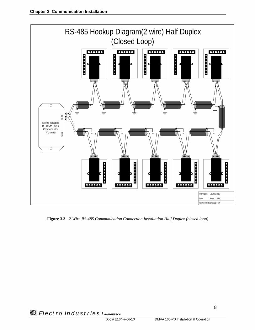
3.5 GROUP 0, FUNCTION 3 - PROGRAMMING PROCEDURE
ððTo change the SYSTEM CONFIGURATION SWITCH settings, follow these steps:
NOTE: PRESS MAX/MIN/LIMITS, AT ANY TIME, BEFORE STORING THE LAST DIGIT OR SWITCH.
Electro Industries
MAX/MIN
MINIMUMLIMITS
NEXT
PHASEPROGPRINT
KVOLTS
VOLTS
FREQUENCY
MAX
MIN
LM2
LM1
BA
C B
C
A
CBA
ABC
Electro Industries
MAX/MIN
MINIMUMLIMITS
NEXT
PHASEPROGPRINT
KVOLTS
VOLTS
FREQUENCY
MAX
MIN
LM2
LM1
BA
C B
C
A
CBA
ABC
Step 1:a. Enter Group Level of Programming Mode,(see Chapter 2).
b. Press MAX/MIN until 0. appears in upper display.
c. Press VPRINTOLTS to activate the Group.
ðð03.0 appears in upper display.
ððLower display indicates current PACK 0 SwitchSettings.
Electro Industries
MAX/MIN
MINIMUMLIMITS
NEXT
PHASEPROGPRINT
KVOLTS
VOLTS
FREQUENCY
MAX
MIN
LM2
LM1
BA
C B
C
A
CBA
ABC
Electro Industries
MAX/MIN
MINIMUMLIMITS
NEXT
PHASEPROGPRINT
KVOLTS
VOLTS
FREQUENCY
MAX
MIN
LM2
LM1
BA
C B
C
A
CBA
ABC
Step 2:a. Press LIMIT until desired PACK appears.
b. Press PRINT to begin Data Entry Sequence.
ððThree dashes appear in lower display.
Step 3:a. Press LIMITS to toggle the segments UP or DOWNfor desired setting.
b. Press PRINT to store and move to the next switch.
See Chapter 6 to Exit.

CHAPTER 4
PROGRAMMING GROUP 1 4.1 SCALE SELECTIONS AND FULL SCALE SETTINGS Programming GROUP 1 functions provide a selection of Full Scale Settings to accommodate the different CTs and PTs. The decimal point may be positioned for maximum resolution. The user can perform Scale Selection in each function. The site technician has a choice of Full Scale selection between volts and kilovolts, and amps and kiloamps. NOTE: DUE TO THE RESOLUTION CAPABILITY, READINGS OVER 2000 COUNTS RESULT IN A LESS STABLE MEASUREMENT.
Tables 4-0 and 4-1 contain Full Scale settings for typical voltages and currents (PT and CT arrangements):
TABLE 4-0 INPUT VOLTAGE PT RATIO FULL SCALE
120 100/1 12.00KV 120 120/1 14.40KV
TABLE 4-1: GROUP 1 PROGRAMMING FORMAT
FUNCTION NUMBER FUNCTION 0. Full Scale Selection for Primary Voltage 1. Full Scale Selection for Secondary voltage E. Exit Programming GROUP 1
4.2 GROUP 1, FUNCTIONS 0-1: FULL SCALE SETTINGS, VOLT & AMP CHANNELS, VOLT & AMP DECIMAL PLACEMENT
To change the VOLT OR AMP FULL SCALE settings (Function 0 and 1, respectively), follow these steps: NOTE: PRESS MAX/MIN/LIMITS, AT ANY TIME, TO CANCEL BEFORE STORING THE LAST DIGIT OR SWITCH.
Electro Industries
MAX/MIN
MINIMUMLIMITS
NEXTPHASE
PROGPRINT
KVOLTS
VOLTS
FREQUENCY
MAXMIN
LM2LM1
BA
C B
C
A
CBAABC
Electro Industries
MAX/MIN
MINIMUMLIMITS
NEXTPHASE
PROGPRINT
KVOLTS
VOLTS
FREQUENCY
MAXMIN
LM2LM1
BA
C B
C
A
CBAABC
Step 1: a. Enter Group Level of Programming Mode, (see Chp. 2). b. Press MAX/MIN until 1. appears in upper display. c. Press PRINT to activate the Group.
Step 2: 10. appears in upper display.
Lower display indicates Full Scale setting.
A segment appears in upper display.
UP signifies - Kilovolts. DOWN signifies - Volts.
a. Press PRINT to begin Data Entry Sequence.
27 Electro Industries / GAUGETECH
Doc # E104-7-06-13 DMVA 100-PS: Programming

Chapter 4 Programming GROUP 1
Electro Industries
MAX/MIN
MINIMUMLIMITS
NEXTPHASE
PROGPRINT
KVOLTS
VOLTS
FREQUENCY
MAXMIN
LM2LM1
BA
C B
C
A
CBAABC
Electro Industries
MAX/MIN
MINIMUMLIMITS
NEXTPHASE
PROGPRINT
KVOLTS
VOLTS
FREQUENCY
MAXMIN
LM2LM1
BA
C B
C
A
CBAABC
ENTERING THE FULL SCALE FACTOR Step 3:
A dash appears in lower display. a. Press LIMITS to move the segment UP or DOWN. b. Press PRINT to store.
DECIMAL POINT SELECTION Step 4: a. Press LIMITS to begin decimal placement. b. Press PRINTS to store
NOTE: THE DECIMAL POINT FOR 1999. DOES NOT APPEAR ON THE DISPLAY.
Electro Industries
MAX/MIN
MINIMUMLIMITS
NEXTPHASE
PROGPRINT
KVOLTS
VOLTS
FREQUENCY
MAXMIN
LM2LM1
BA
C B
C
A
CBAABC
Electro Industries
MAX/MIN
MINIMUMLIMITS
NEXTPHASE
PROGPRINT
KVOLTS
VOLTS
FREQUENCY
MAXMIN
LM2LM1
BA
C B
C
A
CBAABC
Step 5 :
Three dashes appear in lower display. a. Press LIMITS for desired number. • Press LIMTS once and the blank signifies a zero. • Press LIMITS twice and 1 appears. b. Press PRINT to store and move to the next digit.
Repeat this procedure until desired value is entered
When complete, lower display indicates new Full Scale
setting. See Chapter 6 to Exit.
Electro Industries / GAUGETECH
Doc # E104-7-06-13 DMVA 100: Programming
28

CHAPTER 5PROGRAMMING GROUP 2: METER CALIBRATION
29 Electro Industries / GAUGETECH
Doc # E104-7-06-13 DMVA 100-PS: Programming
5.1 STANDARD CALIBRATION
WARNING - READ THIS SECTION CAREFULLY BEFORE PROCEEDING
⌦⌦ Calibration does not need to be accomplished to change CT or PT ratios. (See GROUP 1)
⌦⌦ Meter calibration cannot be performed if the meter is installed for service. The sensing must be connected to a power supply with variable voltage and separate current outputs.
⌦⌦ The calibration procedure requires highly accurate and stable input signals. Incorrect readings result from improper calibration procedures. If unsure, return unit to the factory for calibration.
⌦⌦ BEFORE calibrating any channel, make note of its Full Scale Setting (see Chp. 4). Set the Full Scale in accordance with Table 5-1 for calibration. Restore original Full Scale Setting when calibration is completed.
⌦⌦ The first function in GROUP 2 (STD.CORR) is NOT to be changed by the user. Please make note of the value here (oooooooo) before using any other function in this Group. If the
STD.CORR value is inadvertently lost or changed, contact the factory for assistance.
All sensitive electronic measuring devices drift slightly over time, requiring periodic calibration. We recommendreturning the meter to the factory on a yearly basis.
TABLE 5-0: GROUP 2 PROGRAMMING FORMAT
FUNCTION NUMBER FUNCTIONP. Standard Correction. Factory Procedure only.0. High End Calibration, VOLTS AN1. High End Calibration, VOLTS BN2. High End Calibration, VOLTS CN
The Full Scale and Calibration values should be equal during the calibration procedure. The meter may be rescaledwithout calibrating by changing the full scale in GROUP 1, FUNCTION 0 or 1. (See Table 5-1)
TABLE 5-1: SOURCE, FULL SCALE AND VALUE SETTINGS FOR CALIBRATION
CALIBRATION TYPE/RANGES
CALIB. SOURCENECESSARY
FULL SCALE SETTING CALIBRATION VALUE
VOLTS 120 120V 14.40 14.40

Chapter 5 Programming GROUP 2: Meter Calibration
Electro Industries / GAUGETECH
Doc # E104-7-06-13 DMVA 100: Programming
30
5.2 GROUP 2, FUNCTIONS 0-8: HIGH END CALIBRATION OF VOLTAGE CHANNELS, HIGH & LOW END
CALIBRATION OF AMPERAGE CHANNELS
ððTo change the CALIBRATION, follow these steps:
NOTE: PRESS MAX/MIN. AT ANY TIME, TO CANCEL BEFORE STORING THE LAST DIGIT OR SWITCH.
Electro Industries
MAX/MIN
MINIMUMLIMITS
NEXT
PHASEPROGPRINT
KVOLTS
VOLTS
FREQUENCY
MAX
MIN
LM2
LM1
BA
C B
C
A
CBA
ABC
Electro Industries
MAX/MIN
MINIMUMLIMITS
NEXT
PHASEPROGPRINT
KVOLTS
VOLTS
FREQUENCY
MAX
MIN
LM2
LM1
BA
C B
C
A
CBA
ABC
Step 1:a. Enter Group Level of Programming Mode,(see Chp. 2).
b. Press MAX/MIN/LIMITS until 2. appears in upperdisplay.
c. Press PRINT activate the Group.
ððA one digit password is required to continue.
d. Press LIMITS until 5 appears.
e. Press PRINT to select.
Step 2:ððRefer to Table 5-0 for Function Number thatcorresponds to channel requiring calibration.
a. Press PRINT (to calibrate VOLTS AN) until 20.appears in upper display.
The correct Value is 981
ðð(2P is pre-calibrated. This is a factory set value andshould not be altered).
Electro Industries
MAX/MIN
MINIMUMLIMITS
NEXT
PHASEPROGPRINT
KVOLTS
VOLTS
FREQUENCY
MAX
MIN
LM2
LM1
BA
C B
C
A
CBA
ABC
Electro Industries
MAX/MIN
MINIMUMLIMITS
NEXT
PHASEPROGPRINT
KVOLTS
VOLTS
FREQUENCY
MAX
MIN
LM2
LM1
BA
C B
C
A
CBA
ABC
Step 3:ððApply the calibration to the appropriate channel.
a. Press PRINT to activate calibration.
b. Press LIMITS for desired number.
Press LIMITS once and the blank signifies a zero. Press LIMITS twice and 1 appears.
c. Press PRINT to store and move to the next digit
ððWhen complete, lower display indicates the calibratedreading after 10-15 seconds.
Step 4:a. Press MAX/MIN to exit calibration sequence.
ððProceed to calibrate another function, or exit.
See Chapter 6 to Exit.
¦¦ REPEAT THIS PROCEDURE FOR FUNCTIONS 1 AND 2.

CHAPTER 6
EXITING THE PROGRAMMING MODE
Electro Industries / GAUGETECH
Doc # E104-7-06-13 DMVA 100-PS: Programming
31
NOTE: STEPS TO EXIT THE PROGRAMMING MODE VARIES AS THE PROGRAMMING STAGE VARY.
Exiting the Programming Mode is ALWAYS necessary to store any new changes and to calculate a new checksum.Failure to exit results in a checksum error. The display blanks and the max LED intermittently flashes.
IF YOU ARE LOCATED AT: FUNCTION LEVEL - begin at Step 1GROUP LEVEL - begin at Step 2
Electro Industries
MAX/MIN
MINIMUMLIMITS
NEXT
PHASEPROGPRINT
KVOLTS
VOLTS
FREQUENCY
MAX
MIN
LM2
LM1
BA
C B
C
A
CBA
ABC
Electro Industries
MAX/MIN
MINIMUMLIMITS
NEXT
PHASEPROGPRINT
KVOLTS
VOLTS
FREQUENCY
MAX
MIN
LM2
LM1
BA
C B
C
A
CBA
ABC
Electro Industries
MAX/MIN
MINIMUMLIMITS
NEXT
PHASEPROGPRINT
KVOLTS
VOLTS
FREQUENCY
MAX
MIN
LM2
LM1
BA
C B
C
A
CBA
ABC
EXITING FROM FUNCTION LEVEL EXITING FROM GROUP LEVEL
Step 1:a. Press MAX/MIN until the Groupnumber in upper display is followedby E.
ððThe DMVA 100 re-turns toFunction Level.
Step 1a:a. Press PRINT to exit fromFunction Level to Group Level.
Step 2:a. Press MAX/MIN until E. appearsin upper display.
b. Press PRINT to exit entirely fromProgramming Mode.
YOU HAVE EXITED THE PROGRAMMING MODE.
AFTER A MOMENT, THE METER RETURNS TO THE OPERATING MODE.


![20 kV-Leitung (wird abgebaut) · PS PS PS PS PS P' P' Versorgungsleitungen werden verlegt! 20 kV-Leitung (wird abgebaut) W^ > ] µ v P Z K ( o Z v Á W^ V V 110.00 110.00 3.00 8.00](https://img.pdfslide.net/doc/110x75/608cbd0fb83f3468f808b8e2/20-kv-leitung-wird-abgebaut-ps-ps-ps-ps-ps-p-p-versorgungsleitungen-werden-verlegt.jpg)