Embed Size (px)
Citation preview
DMVPN, czyli Transport Independent Design dla IWAN Adam Śniegórski Systems Engineer, CCIE R&S Solutions & Innovation
2 © 2013-2014 Cisco and/or its affiliates. All rights reserved.
MPLS
Oddział
3G/4G-LTE
AVC
Internet
Chmura prywatna
Wirtualna chmura
prywatna
Chmura publiczna WAAS
Akamai PfRv3
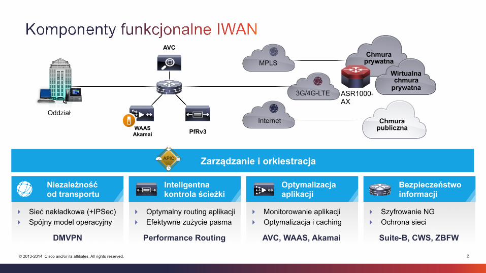
Niezależność od transportu
Inteligentna kontrola ścieżki
Optymalizacja aplikacji
Bezpieczeństwo informacji
! Sieć nakładkowa (+IPSec) ! Spójny model operacyjny
! Optymalny routing aplikacji ! Efektywne zużycie pasma
! Monitorowanie aplikacji ! Optymalizacja i caching
! Szyfrowanie NG ! Ochrona sieci
DMVPN Performance Routing AVC, WAAS, Akamai Suite-B, CWS, ZBFW
Zarządzanie i orkiestracja
ASR1000-AX
3 © 2013-2014 Cisco and/or its affiliates. All rights reserved.
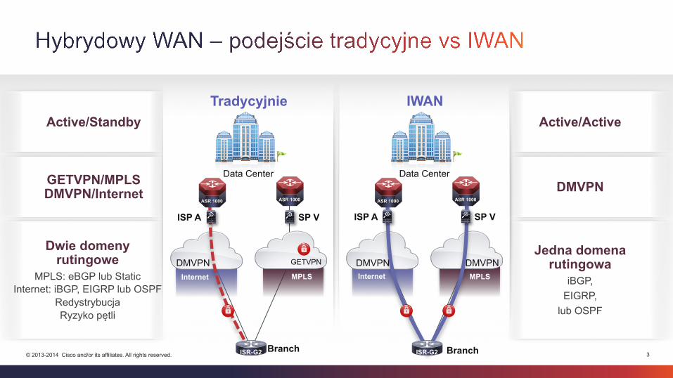
Dwie domeny rutingowe
MPLS: eBGP lub Static Internet: iBGP, EIGRP lub OSPF
Redystrybucja Ryzyko pętli
GETVPN/MPLS DMVPN/Internet
Active/Standby
Jedna domena rutingowa
iBGP, EIGRP,
lub OSPF
DMVPN
Active/Active IWAN
Internet MPLS
Branch
DMVPN DMVPN
ISR-G2
ISP A SP V
ASR 1000 ASR 1000
Data Center
Tradycyjnie
Internet MPLS
Branch
DMVPN GETVPN
ISR-G2
ASR 1000 ASR 1000
ISP A SP V
Data Center
4 © 2013-2014 Cisco and/or its affiliates. All rights reserved.
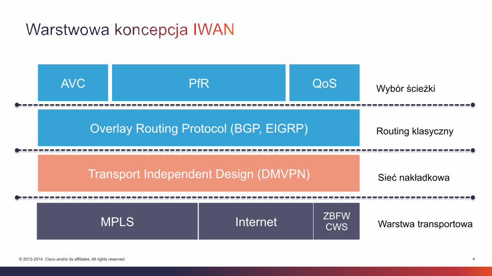
MPLS Internet
Overlay Routing Protocol (BGP, EIGRP)
Transport Independent Design (DMVPN)
PfR AVC QoS
Warstwa transportowa
Sieć nakładkowa
Routing klasyczny
Wybór ścieżki
ZBFW CWS
5 © 2013-2014 Cisco and/or its affiliates. All rights reserved.
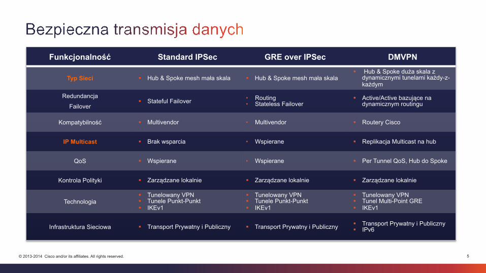
Funkcjonalność Standard IPSec GRE over IPSec DMVPN
Typ Sieci § Hub & Spoke mesh mała skala § Hub & Spoke mesh mała skala § Hub & Spoke duża skala z
dynamicznymi tunelami każdy-z-każdym
Redundancja
Failover § Stateful Failover • Routing
• Stateless Failover § Active/Active bazujące na
dynamicznym routingu
Kompatybilność § Multivendor • Multivendor § Routery Cisco
IP Multicast § Brak wsparcia • Wspierane § Replikacja Multicast na hub
QoS § Wspierane • Wspierane § Per Tunnel QoS, Hub do Spoke
Kontrola Polityki § Zarządzane lokalnie § Zarządzane lokalnie § Zarządzane lokalnie
Technologia § Tunelowany VPN § Tunele Punkt-Punkt § IKEv1
§ Tunelowany VPN § Tunele Punkt-Punkt § IKEv1
§ Tunelowany VPN § Tunel Multi-Point GRE § IKEv1
Infrastruktura Sieciowa § Transport Prywatny i Publiczny § Transport Prywatny i Publiczny § Transport Prywatny i Publiczny § IPv6
6 © 2013-2014 Cisco and/or its affiliates. All rights reserved.
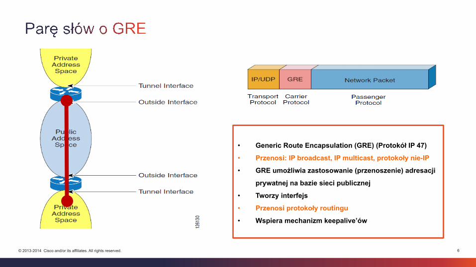
• Generic Route Encapsulation (GRE) (Protokół IP 47)
• Przenosi: IP broadcast, IP multicast, protokoły nie-IP
• GRE umożliwia zastosowanie (przenoszenie) adresacji
prywatnej na bazie sieci publicznej
• Tworzy interfejs
• Przenosi protokoły routingu
• Wspiera mechanizm keepalive’ów
7 © 2013-2014 Cisco and/or its affiliates. All rights reserved.
Dane
Zaszyfrowane
ESP HDR
IP HDR
GRE HDR
Tunel IPsec Tunel GRE L3
IP HDR
IP HDR Dane IP
HDR Dane IP HDR
GRE HDR
IP HDR
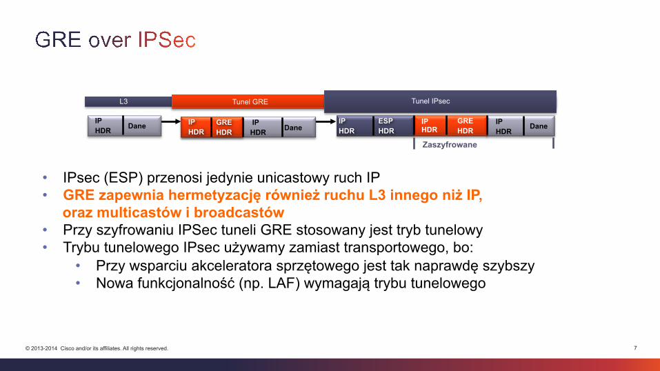
• IPsec (ESP) przenosi jedynie unicastowy ruch IP • GRE zapewnia hermetyzację również ruchu L3 innego niż IP,
oraz multicastów i broadcastów • Przy szyfrowaniu IPSec tuneli GRE stosowany jest tryb tunelowy • Trybu tunelowego IPsec używamy zamiast transportowego, bo:
• Przy wsparciu akceleratora sprzętowego jest tak naprawdę szybszy • Nowa funkcjonalność (np. LAF) wymagają trybu tunelowego
8 © 2013-2014 Cisco and/or its affiliates. All rights reserved.
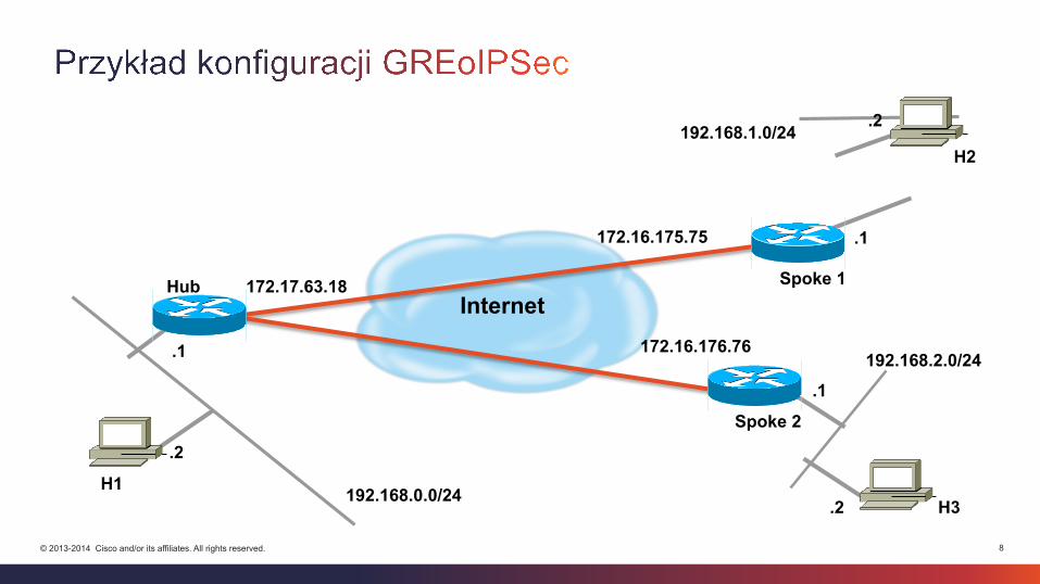
192.168.0.0/24
.1
.2
192.168.1.0/24 .2
.1
172.17.63.18
172.16.175.75
H1
H2
Internet
H3
192.168.2.0/24 172.16.176.76
.1
.2
Spoke 1 Hub
Spoke 2
9 © 2013-2014 Cisco and/or its affiliates. All rights reserved.
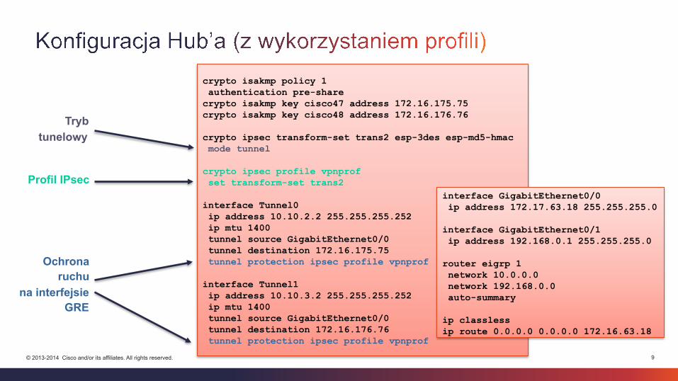
crypto isakmp policy 1 authentication pre-share crypto isakmp key cisco47 address 172.16.175.75 crypto isakmp key cisco48 address 172.16.176.76 crypto ipsec transform-set trans2 esp-3des esp-md5-hmac mode tunnel crypto ipsec profile vpnprof set transform-set trans2 interface Tunnel0 ip address 10.10.2.2 255.255.255.252 ip mtu 1400 tunnel source GigabitEthernet0/0 tunnel destination 172.16.175.75 tunnel protection ipsec profile vpnprof interface Tunnel1 ip address 10.10.3.2 255.255.255.252 ip mtu 1400 tunnel source GigabitEthernet0/0 tunnel destination 172.16.176.76 tunnel protection ipsec profile vpnprof
interface GigabitEthernet0/0 ip address 172.17.63.18 255.255.255.0 interface GigabitEthernet0/1 ip address 192.168.0.1 255.255.255.0 router eigrp 1 network 10.0.0.0 network 192.168.0.0 auto-summary ip classless ip route 0.0.0.0 0.0.0.0 172.16.63.18
Tryb tunelowy
Profil IPsec
Ochrona ruchu
na interfejsie GRE
10 © 2013-2014 Cisco and/or its affiliates. All rights reserved.
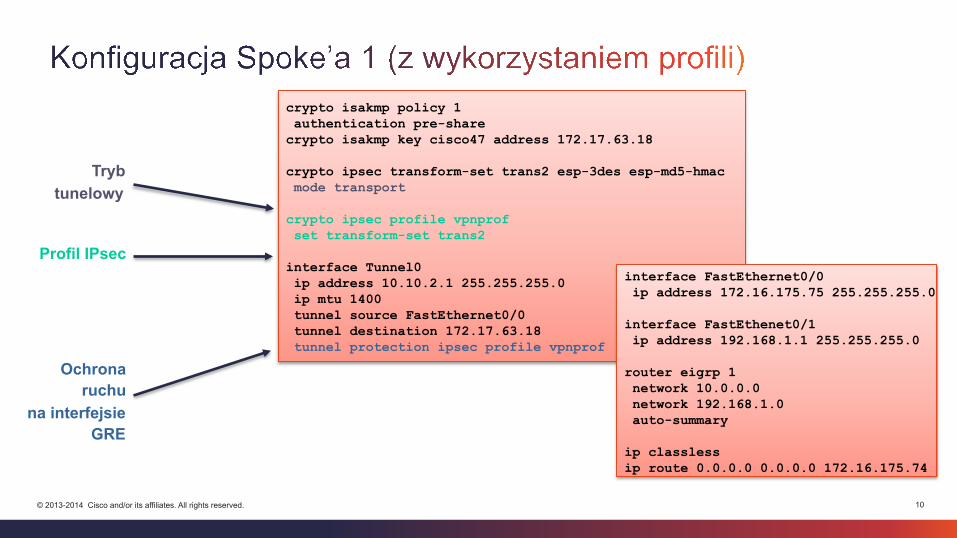
Tryb tunelowy
Profil IPsec
Ochrona ruchu
na interfejsie GRE
crypto isakmp policy 1 authentication pre-share crypto isakmp key cisco47 address 172.17.63.18 crypto ipsec transform-set trans2 esp-3des esp-md5-hmac mode transport crypto ipsec profile vpnprof set transform-set trans2 interface Tunnel0 ip address 10.10.2.1 255.255.255.0 ip mtu 1400 tunnel source FastEthernet0/0 tunnel destination 172.17.63.18 tunnel protection ipsec profile vpnprof
interface FastEthernet0/0 ip address 172.16.175.75 255.255.255.0 interface FastEthenet0/1 ip address 192.168.1.1 255.255.255.0 router eigrp 1 network 10.0.0.0 network 192.168.1.0 auto-summary ip classless ip route 0.0.0.0 0.0.0.0 172.16.175.74

11 © 2013-2014 Cisco and/or its affiliates. All rights reserved.
Tryb tunelowy
Profil IPsec
Ochrona ruchu
na interfejsie GRE
crypto isakmp policy 1 authentication pre-share crypto isakmp key cisco48 address 172.17.63.18 crypto ipsec transform-set trans2 esp-3des esp-md5-hmac mode transport crypto ipsec profile vpnprof set transform-set trans2 interface Tunnel0 ip address 10.10.3.1 255.255.255.0 ip mtu 1400 tunnel source FastEthernet0/0 tunnel destination 172.17.63.18 tunnel protection ipsec profile vpnprof
interface FastEthernet0/0 ip address 172.16.176.76 255.255.255.0 interface FastEthenet0/1 ip address 192.168.2.1 255.255.255.0 router eigrp 1 network 10.0.0.0 network 192.168.2.0 auto-summary ip classless ip route 0.0.0.0 0.0.0.0 172.16.176.75
12 © 2013-2014 Cisco and/or its affiliates. All rights reserved.
Spoke 1
Tunele statyczne
Tunele dynamiczne
Statyczny adres IP
Dynamiczny adres IP
Hub
VPN Spoke n
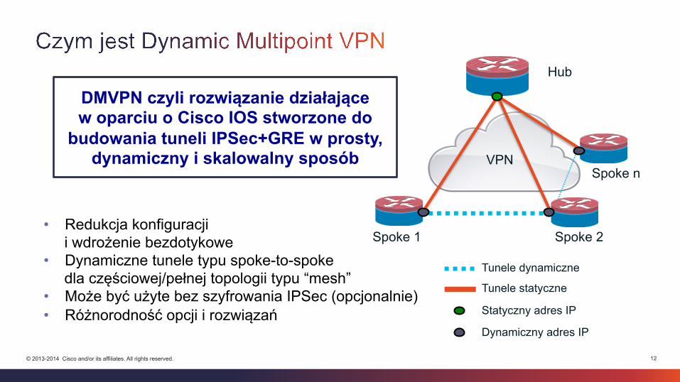
Spoke 2 • Redukcja konfiguracji
i wdrożenie bezdotykowe • Dynamiczne tunele typu spoke-to-spoke
dla częściowej/pełnej topologii typu “mesh” • Może być użyte bez szyfrowania IPSec (opcjonalnie) • Różnorodność opcji i rozwiązań
DMVPN czyli rozwiązanie działające w oparciu o Cisco IOS stworzone do
budowania tuneli IPSec+GRE w prosty, dynamiczny i skalowalny sposób
13 © 2013-2014 Cisco and/or its affiliates. All rights reserved.
Spoke 1
Tunele statyczne
Tunele dynamiczne
Statyczny adres IP
Dynamiczny adres IP
Hub
VPN Spoke n
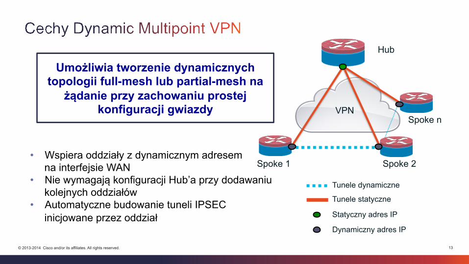
Spoke 2 • Wspiera oddziały z dynamicznym adresem
na interfejsie WAN • Nie wymagają konfiguracji Hub’a przy dodawaniu
kolejnych oddziałów • Automatyczne budowanie tuneli IPSEC
inicjowane przez oddział
Umożliwia tworzenie dynamicznych topologii full-mesh lub partial-mesh na żądanie przy zachowaniu prostej
konfiguracji gwiazdy
14 © 2013-2014 Cisco and/or its affiliates. All rights reserved.
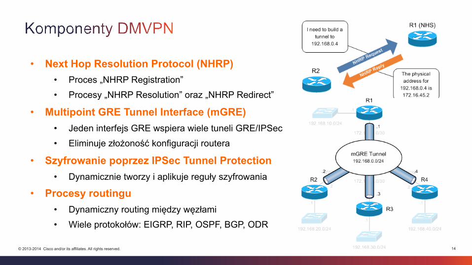
• Next Hop Resolution Protocol (NHRP) • Proces „NHRP Registration” • Procesy „NHRP Resolution” oraz „NHRP Redirect”
• Multipoint GRE Tunnel Interface (mGRE) • Jeden interfejs GRE wspiera wiele tuneli GRE/IPSec • Eliminuje złożoność konfiguracji routera
• Szyfrowanie poprzez IPSec Tunnel Protection • Dynamicznie tworzy i aplikuje reguły szyfrowania
• Procesy routingu • Dynamiczny routing między węzłami • Wiele protokołów: EIGRP, RIP, OSPF, BGP, ODR
15 © 2013-2014 Cisco and/or its affiliates. All rights reserved.
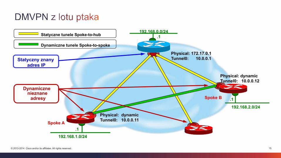
Dynamiczne tunele Spoke-to-spoke
Spoke A
Spoke B 192.168.2.0/24
.1
192.168.1.0/24 .1
192.168.0.0/24 .1
Physical: 172.17.0.1 Tunnel0: 10.0.0.1
Physical: dynamic Tunnel0: 10.0.0.11
Physical: dynamic Tunnel0: 10.0.0.12
Statyczne tunele Spoke-to-hub
Statyczny znany adres IP
Dynamiczne nieznane adresy
16 © 2013-2014 Cisco and/or its affiliates. All rights reserved.
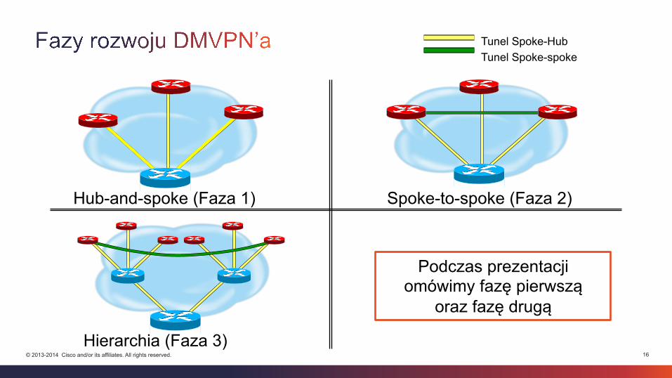
Tunel Spoke-Hub Tunel Spoke-spoke
Hub-and-spoke (Faza 1) Spoke-to-spoke (Faza 2)
Hierarchia (Faza 3)
Podczas prezentacji omówimy fazę pierwszą
oraz fazę drugą
17 © 2013-2014 Cisco and/or its affiliates. All rights reserved.
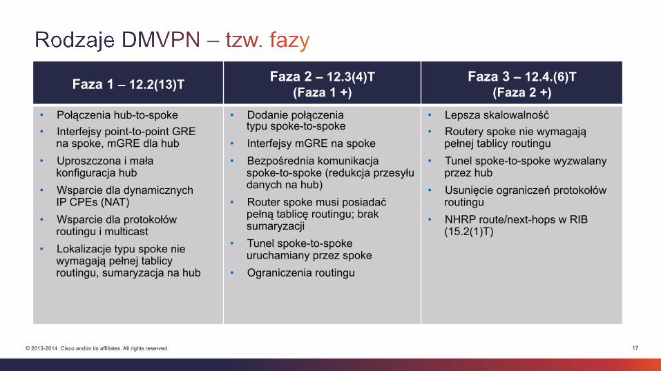
Faza 1 – 12.2(13)T Faza 2 – 12.3(4)T (Faza 1 +)
Faza 3 – 12.4.(6)T (Faza 2 +)
• Połączenia hub-to-spoke • Interfejsy point-to-point GRE
na spoke, mGRE dla hub • Uproszczona i mała
konfiguracja hub • Wsparcie dla dynamicznych
IP CPEs (NAT) • Wsparcie dla protokołów
routingu i multicast • Lokalizacje typu spoke nie
wymagają pełnej tablicy routingu, sumaryzacja na hub
• Dodanie połączenia typu spoke-to-spoke
• Interfejsy mGRE na spoke • Bezpośrednia komunikacja
spoke-to-spoke (redukcja przesyłu danych na hub)
• Router spoke musi posiadać pełną tablicę routingu; brak sumaryzacji
• Tunel spoke-to-spoke uruchamiany przez spoke
• Ograniczenia routingu
• Lepsza skalowalność • Routery spoke nie wymagają
pełnej tablicy routingu • Tunel spoke-to-spoke wyzwalany
przez hub • Usunięcie ograniczeń protokołów
routingu • NHRP route/next-hops w RIB
(15.2(1)T)
18 © 2013-2014 Cisco and/or its affiliates. All rights reserved.
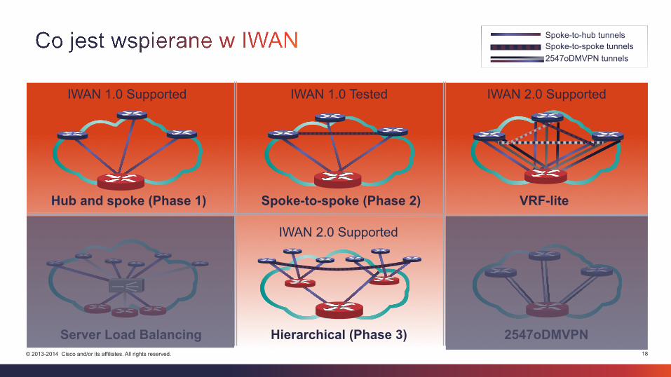
Spoke-to-hub tunnels Spoke-to-spoke tunnels 2547oDMVPN tunnels
Hub and spoke (Phase 1) Spoke-to-spoke (Phase 2)
Server Load Balancing Hierarchical (Phase 3)
VRF-lite
2547oDMVPN
IWAN 1.0 Supported IWAN 2.0 Supported IWAN 1.0 Tested
IWAN 2.0 Supported
19 © 2013-2014 Cisco and/or its affiliates. All rights reserved.
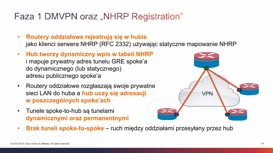
• Routery oddziałowe rejestrują się w hubie jako klienci serwera NHRP (RFC 2332) używając statyczne mapowanie NHRP
• Hub tworzy dynamiczny wpis w tabeli NHRP i mapuje prywatny adres tunelu GRE spoke’a do dynamicznego (lub statycznego) adresu publicznego spoke’a
• Routery oddziałowe rozgłaszają swoje prywatne sieci LAN do huba a hub uczy się adresacji w poszczególnych spoke’ach
• Tunele spoke-to-hub są tunelami dynamicznymi oraz permanentnymi
• Brak tuneli spoke-to-spoke – ruch między oddziałami przesyłany przez hub
VPN
20 © 2013-2014 Cisco and/or its affiliates. All rights reserved.
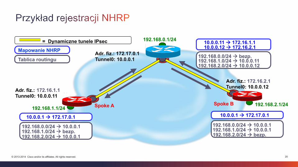
Spoke A 192.168.1.1/24
= Dynamiczne tunele IPsec
192.168.2.1/24
Adr. fiz.: 172.17.0.1 Tunnel0: 10.0.0.1
Spoke B
Adr. fiz.: (dynamiczny) Tunnel0: 10.0.0.11
Adr. fiz.: (dynamiczny) Tunnel0: 10.0.0.12
10.0.0.1 à 172.17.0.1 10.0.0.1 à 172.17.0.1
10.0.0.11 à 172.16.1.1 10.0.0.12 à 172.16.2.1
192.168.0.1/24
192.168.1.0/24 à 10.0.0.1 192.168.2.0/24 à 10.0.0.1
192.168.0.0/24 à 10.0.0.1 192.168.0.0/24 à 10.0.0.1
192.168.1.0/24 à 10.0.0.11 192.168.2.0/24 à 10.0.0.12
192.168.1.0/24 à bezp. 192.168.2.0/24 à bezp.
192.168.0.0/24 à bezp. Mapowanie NHRP
Tablica routingu
172.16.1.1
172.16.2.1
21 © 2013-2014 Cisco and/or its affiliates. All rights reserved.
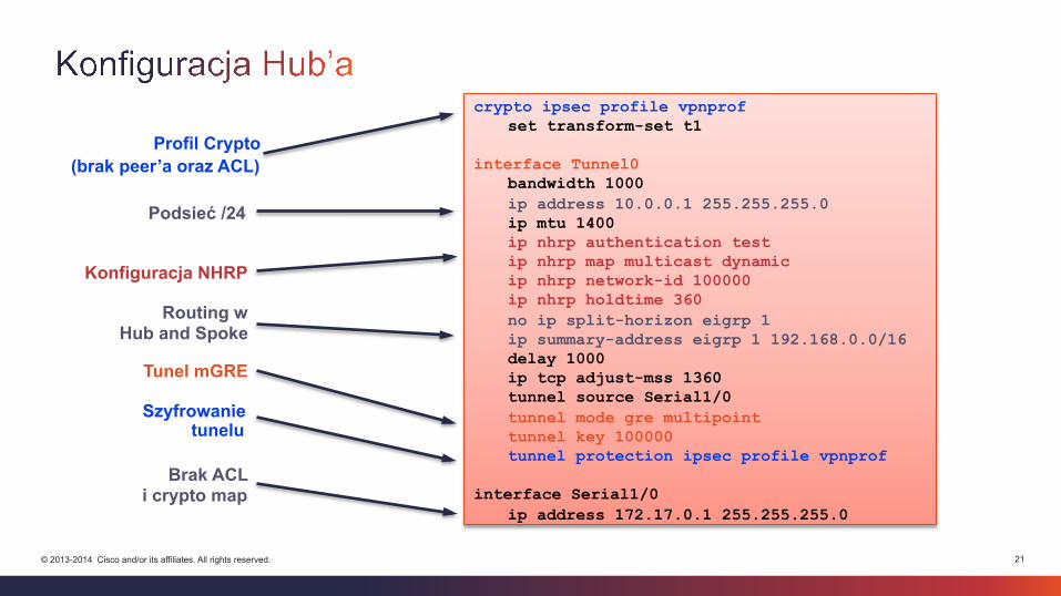
Brak ACL i crypto map
Profil Crypto (brak peer’a oraz ACL)
Konfiguracja NHRP
Tunel mGRE
Szyfrowanie tunelu
Podsieć /24
Routing w Hub and Spoke
crypto ipsec profile vpnprof set transform-set t1
interface Tunnel0
bandwidth 1000 ip address 10.0.0.1 255.255.255.0 ip mtu 1400 ip nhrp authentication test ip nhrp map multicast dynamic ip nhrp network-id 100000 ip nhrp holdtime 360 no ip split-horizon eigrp 1 ip summary-address eigrp 1 192.168.0.0/16 delay 1000 ip tcp adjust-mss 1360 tunnel source Serial1/0 tunnel mode gre multipoint tunnel key 100000 tunnel protection ipsec profile vpnprof
interface Serial1/0
ip address 172.17.0.1 255.255.255.0

22 © 2013-2014 Cisco and/or its affiliates. All rights reserved.
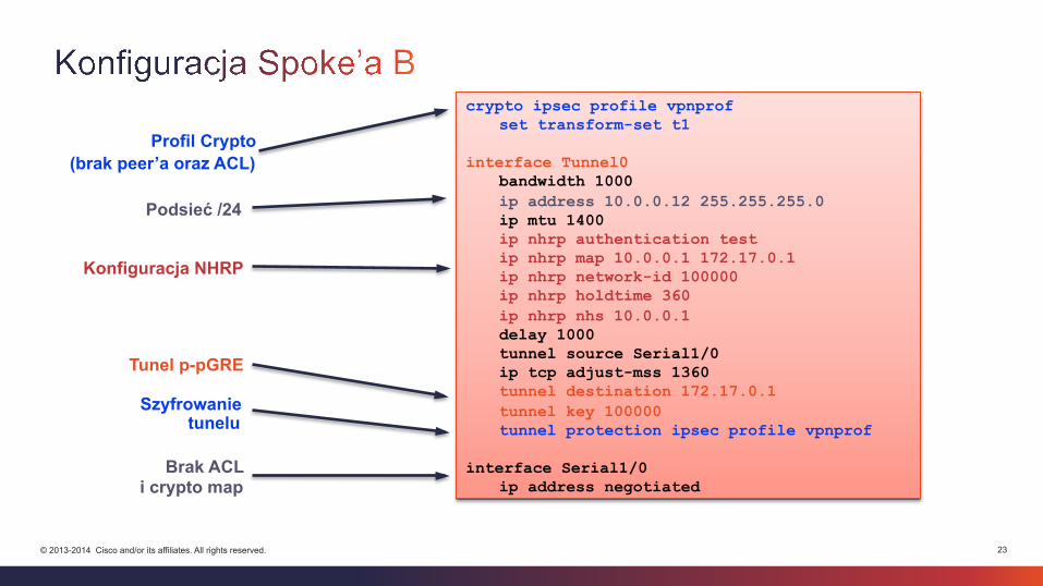
Tunel p-pGRE
Profil Crypto (brak peer’a oraz ACL)
Konfiguracja NHRP
Podsieć /24
Brak ACL i crypto map
Szyfrowanie tunelu
crypto ipsec profile vpnprof set transform-set t1
interface Tunnel0
bandwidth 1000 ip address 10.0.0.11 255.255.255.0 ip mtu 1400 ip nhrp authentication test ip nhrp map 10.0.0.1 172.17.0.1 ip nhrp network-id 100000 ip nhrp holdtime 360 ip nhrp nhs 10.0.0.1 delay 1000 tunnel source Serial1/0 ip tcp adjust-mss 1360 tunnel destination 172.17.0.1 tunnel key 100000 tunnel protection ipsec profile vpnprof
interface Serial1/0
ip address negotiated
23 © 2013-2014 Cisco and/or its affiliates. All rights reserved.
Tunel p-pGRE
Profil Crypto (brak peer’a oraz ACL)
Konfiguracja NHRP
Podsieć /24
Brak ACL i crypto map
Szyfrowanie tunelu
crypto ipsec profile vpnprof set transform-set t1
interface Tunnel0
bandwidth 1000 ip address 10.0.0.12 255.255.255.0 ip mtu 1400 ip nhrp authentication test ip nhrp map 10.0.0.1 172.17.0.1 ip nhrp network-id 100000 ip nhrp holdtime 360 ip nhrp nhs 10.0.0.1 delay 1000 tunnel source Serial1/0 ip tcp adjust-mss 1360 tunnel destination 172.17.0.1 tunnel key 100000 tunnel protection ipsec profile vpnprof
interface Serial1/0
ip address negotiated
24 © 2013-2014 Cisco and/or its affiliates. All rights reserved.
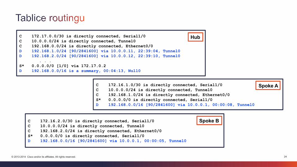
C 172.17.0.0/30 is directly connected, Serial1/0 C 10.0.0.0/24 is directly connected, Tunnel0 C 192.168.0.0/24 is directly connected, Ethernet0/0 D 192.168.1.0/24 [90/2841600] via 10.0.0.11, 22:39:04, Tunnel0 D 192.168.2.0/24 [90/2841600] via 10.0.0.12, 22:39:10, Tunnel0 . . . S* 0.0.0.0/0 [1/0] via 172.17.0.2 D 192.168.0.0/16 is a summary, 00:04:13, Null0
C 172.16.1.0/30 is directly connected, Serial1/0 C 10.0.0.0/24 is directly connected, Tunnel0 C 192.168.1.0/24 is directly connected, Ethernet0/0 S* 0.0.0.0/0 is directly connected, Serial1/0 D 192.168.0.0/16 [90/2841600] via 10.0.0.1, 00:00:08, Tunnel0
C 172.16.2.0/30 is directly connected, Serial1/0 C 10.0.0.0/24 is directly connected, Tunnel0 C 192.168.2.0/24 is directly connected, Ethernet0/0 S* 0.0.0.0/0 is directly connected, Serial1/0 D 192.168.0.0/16 [90/2841600] via 10.0.0.1, 00:00:05, Tunnel0
Spoke A
Spoke B
Hub
25 © 2013-2014 Cisco and/or its affiliates. All rights reserved.
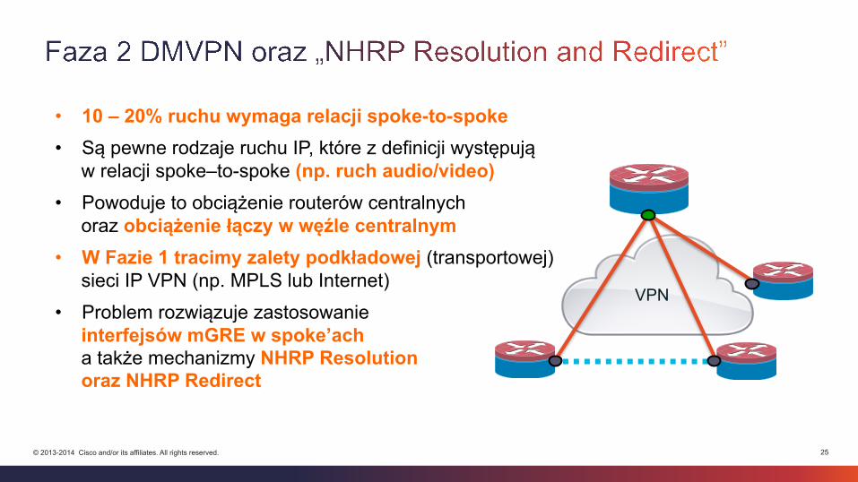
• 10 – 20% ruchu wymaga relacji spoke-to-spoke • Są pewne rodzaje ruchu IP, które z definicji występują
w relacji spoke–to-spoke (np. ruch audio/video) • Powoduje to obciążenie routerów centralnych
oraz obciążenie łączy w węźle centralnym • W Fazie 1 tracimy zalety podkładowej (transportowej)
sieci IP VPN (np. MPLS lub Internet)
• Problem rozwiązuje zastosowanie interfejsów mGRE w spoke’ach a także mechanizmy NHRP Resolution oraz NHRP Redirect
VPN
26 © 2013-2014 Cisco and/or its affiliates. All rights reserved.
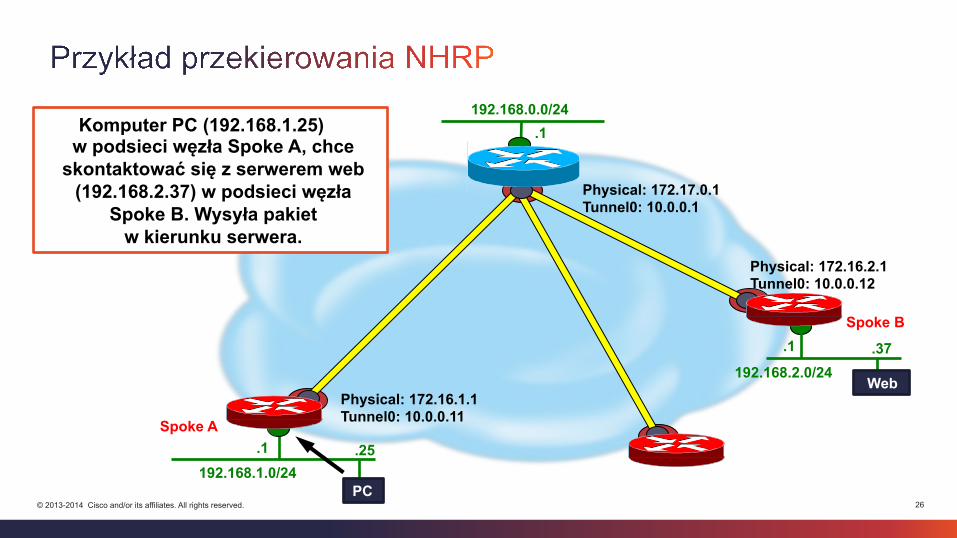
Spoke A
Spoke B
192.168.2.0/24
.1
192.168.1.0/24
.1
192.168.0.0/24 .1
Physical: 172.17.0.1 Tunnel0: 10.0.0.1
Physical: 172.16.1.1 Tunnel0: 10.0.0.11
Physical: 172.16.2.1 Tunnel0: 10.0.0.12
Web
.37
.25
Komputer PC (192.168.1.25) w podsieci węzła Spoke A, chce
skontaktować się z serwerem web (192.168.2.37) w podsieci węzła
Spoke B. Wysyła pakiet w kierunku serwera.
PC
27 © 2013-2014 Cisco and/or its affiliates. All rights reserved.
Spoke A
Spoke B
192.168.2.0/24 .1
192.168.1.0/24 .1
.1
Physical: 172.17.0.1 Tunnel0: 10.0.0.1
Physical: 172.16.1.1 Tunnel0: 10.0.0.11
Physical: 172.16.2.1 Tunnel0: 10.0.0.12
.37
.25
192.168.0.0/24 à 10.0.0.1 192.168.2.0/24 à 10.0.0.12
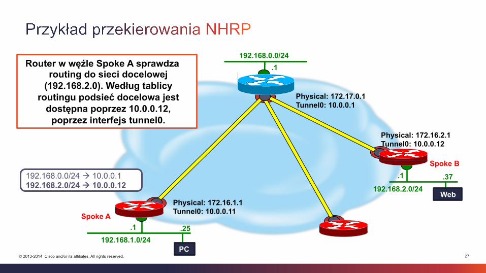
192.168.0.0/24 Router w węźle Spoke A sprawdza
routing do sieci docelowej (192.168.2.0). Według tablicy
routingu podsieć docelowa jest dostępna poprzez 10.0.0.12,
poprzez interfejs tunnel0.
Web
PC
28 © 2013-2014 Cisco and/or its affiliates. All rights reserved.
Spoke A
Spoke B
192.168.2.0/24 .1
192.168.1.0/24 .1
.1
Physical: 172.17.0.1 Tunnel0: 10.0.0.1
Physical: 172.16.1.1 Tunnel0: 10.0.0.11
Physical: 172.16.2.1 Tunnel0: 10.0.0.12
.37
.25
10.0.0.1 à 172.17.0.1
192.168.0.0/24
Web
PC
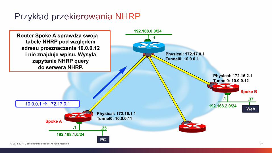
Router Spoke A sprawdza swoją tabelę NHRP pod względem
adresu przeznaczenia 10.0.0.12 i nie znajduje wpisu. Wysyła
zapytanie NHRP query do serwera NHRP.
29 © 2013-2014 Cisco and/or its affiliates. All rights reserved.
Spoke A
Spoke B
192.168.2.0/24 .1
192.168.1.0/24 .1
.1
Physical: 172.17.0.1 Tunnel0: 10.0.0.1
Physical: 172.16.1.1 Tunnel0: 10.0.0.11
Physical: 172.16.2.1 Tunnel0: 10.0.0.12
.37
.25
10.0.0.11 à 172.16.1.1 10.0.0.12 à 172.16.2.1 . . . . . .
192.168.0.0/24
Web
PC
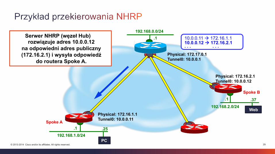
Serwer NHRP (węzeł Hub) rozwiązuje adres 10.0.0.12
na odpowiedni adres publiczny (172.16.2.1) i wysyła odpowiedź
do routera Spoke A.
30 © 2013-2014 Cisco and/or its affiliates. All rights reserved. = Dynamiczny, tymczasowy tunel IPSec Spoke-to-spoke
Spoke A
Spoke B
192.168.2.0/24 .1
192.168.1.0/24 .1
.1
Physical: 172.17.0.1 Tunnel0: 10.0.0.1
Physical: 172.16.1.1 Tunnel0: 10.0.0.11
Physical: 172.16.2.1 Tunnel0: 10.0.0.12
.37
.25
10.0.0.1 à 172.17.0.1 10.0.0.12 à 172.16.2.1
192.168.0.0/24
Web
PC
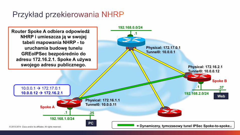
Router Spoke A odbiera odpowiedź NHRP i umieszcza ją w swojej tabeli mapowania NHRP - to uruchamia budowę tunelu
GREoIPSec bezpośrednio do adresu 172.16.2.1. Spoke A używa
swojego adresu publicznego.
31 © 2013-2014 Cisco and/or its affiliates. All rights reserved.
Spoke A
Spoke B
192.168.2.0/24 .1
192.168.1.0/24 .1
.1
Physical: 172.17.0.1 Tunnel0: 10.0.0.1
Physical: 172.16.1.1 Tunnel0: 10.0.0.11
Physical: 172.16.2.1 Tunnel0: 10.0.0.12
.37
.25
= Dynamiczny, tymczasowy tunel IPSec Spoke-to-spoke
192.168.0.0/24
Web
PC
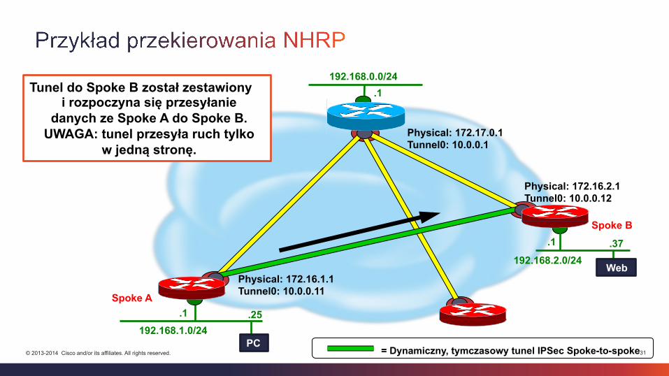
Tunel do Spoke B został zestawiony i rozpoczyna się przesyłanie
danych ze Spoke A do Spoke B. UWAGA: tunel przesyła ruch tylko
w jedną stronę.
32 © 2013-2014 Cisco and/or its affiliates. All rights reserved.
Spoke A
Spoke B
192.168.2.0/24 .1
192.168.1.0/24 .1
.1
Physical: 172.17.0.1 Tunnel0: 10.0.0.1
Physical: 172.16.1.1 Tunnel0: 10.0.0.11
Physical: 172.16.2.1 Tunnel0: 10.0.0.12
.37
.25
= Dynamiczny, tymczasowy tunel IPSec Spoke-to-spoke
192.168.0.0/24
Web
PC
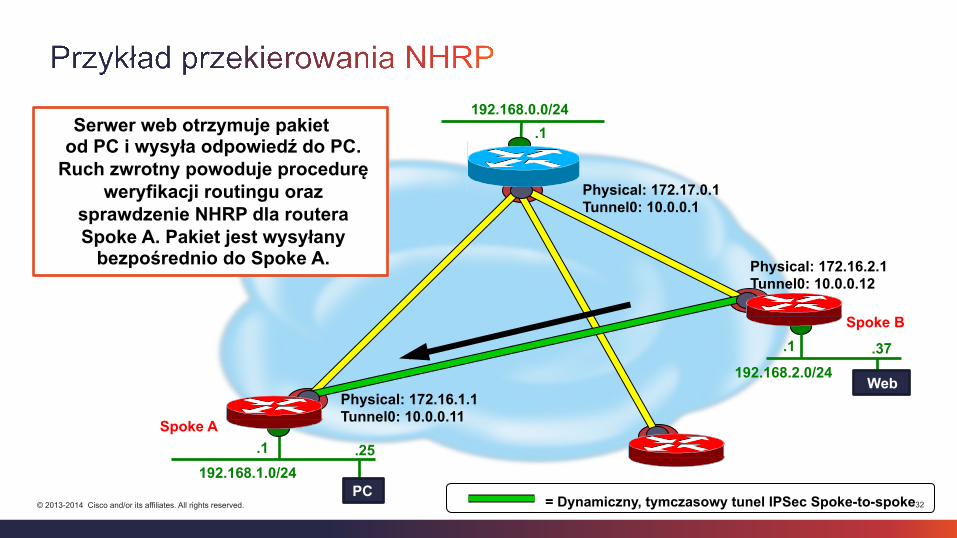
Serwer web otrzymuje pakiet od PC i wysyła odpowiedź do PC.
Ruch zwrotny powoduje procedurę weryfikacji routingu oraz
sprawdzenie NHRP dla routera Spoke A. Pakiet jest wysyłany
bezpośrednio do Spoke A.
33 © 2013-2014 Cisco and/or its affiliates. All rights reserved.
Spoke A
Spoke B
192.168.2.0/24 .1
192.168.1.0/24 .1
.1
Physical: 172.17.0.1 Tunnel0: 10.0.0.1
Physical: 172.16.1.1 Tunnel0: 10.0.0.11
Physical: 172.16.2.1 Tunnel0: 10.0.0.12
.37
.25
10.0.0.1 à 172.17.0.1
10.0.0.12 à 172.16.2.1
= Dynamiczny, tymczasowy tunel IPSec Spoke-to-spoke
192.168.0.0/24
Web
PC
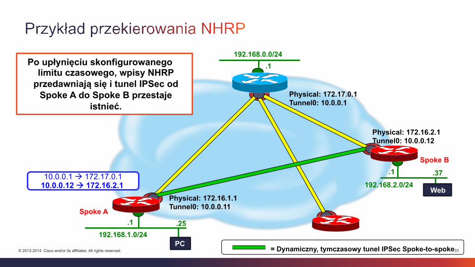
Po upłynięciu skonfigurowanego limitu czasowego, wpisy NHRP
przedawniają się i tunel IPSec od Spoke A do Spoke B przestaje
istnieć.

34 © 2013-2014 Cisco and/or its affiliates. All rights reserved.
crypto isakmp policy 1 encr aes authentication pre-share group 2 crypto isakmp key cisco123 address 0.0.0.0 0.0.0.0 crypto ipsec transform-set TSET esp-aes esp-sha-hmac mode transport crypto ipsec profile TP set transform-set TSET
interface Tunnel ip address 10.0.0.1 255.255.255.0 no ip redirects ip nhrp authentication cisco ip nhrp map multicast dynamic ip nhrp network-id 1111 ip nhrp redirect tunnel key 10 no ip split-horizon eigrp 10 ip summary-address eigrp 10 192.168.0.0 255.255.0.0 tunnel source FastEthernet0/0 tunnel mode gre multipoint tunnel protection ipsec profile TP
35 © 2013-2014 Cisco and/or its affiliates. All rights reserved.
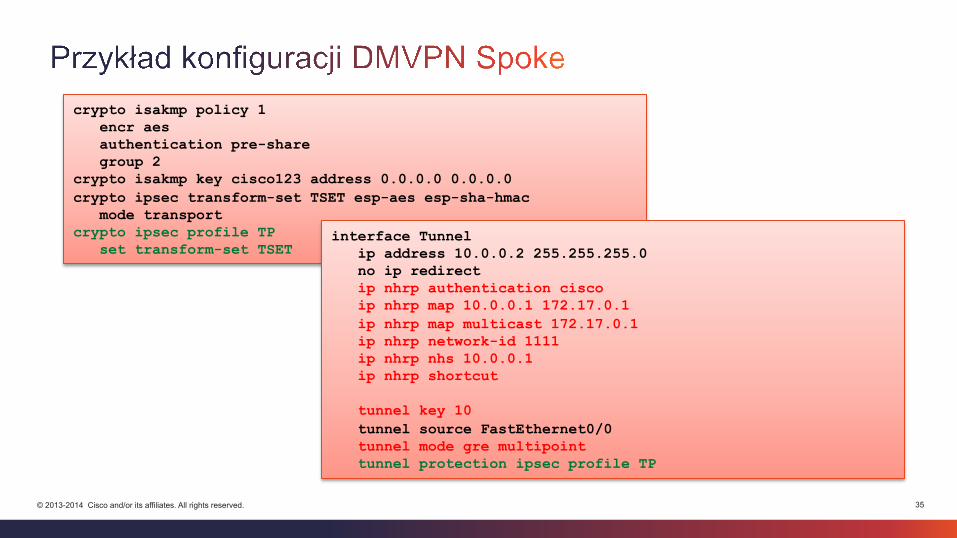
crypto isakmp policy 1 encr aes authentication pre-share group 2 crypto isakmp key cisco123 address 0.0.0.0 0.0.0.0 crypto ipsec transform-set TSET esp-aes esp-sha-hmac mode transport crypto ipsec profile TP set transform-set TSET
interface Tunnel ip address 10.0.0.2 255.255.255.0 no ip redirect ip nhrp authentication cisco ip nhrp map 10.0.0.1 172.17.0.1 ip nhrp map multicast 172.17.0.1 ip nhrp network-id 1111 ip nhrp nhs 10.0.0.1 ip nhrp shortcut tunnel key 10 tunnel source FastEthernet0/0 tunnel mode gre multipoint tunnel protection ipsec profile TP
36 © 2013-2014 Cisco and/or its affiliates. All rights reserved.
36
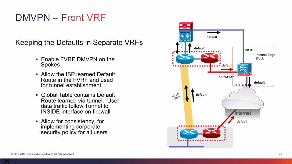
§ Enable FVRF DMVPN on the Spokes
§ Allow the ISP learned Default Route in the FVRF and used for tunnel establishment
§ Global Table contains Default Route learned via tunnel. User data traffic follow Tunnel to INSIDE interface on firewall
§ Allow for consistency for implementing corporate security policy for all users
Keeping the Defaults in Separate VRFs
Internet
VPN-DMZ
Internet Edge Block
default
default
INSIDE
OUTSIDE default
EIGRP
(200)
default
default
EIG
RP
default
Internet
37 © 2013-2014 Cisco and/or its affiliates. All rights reserved.
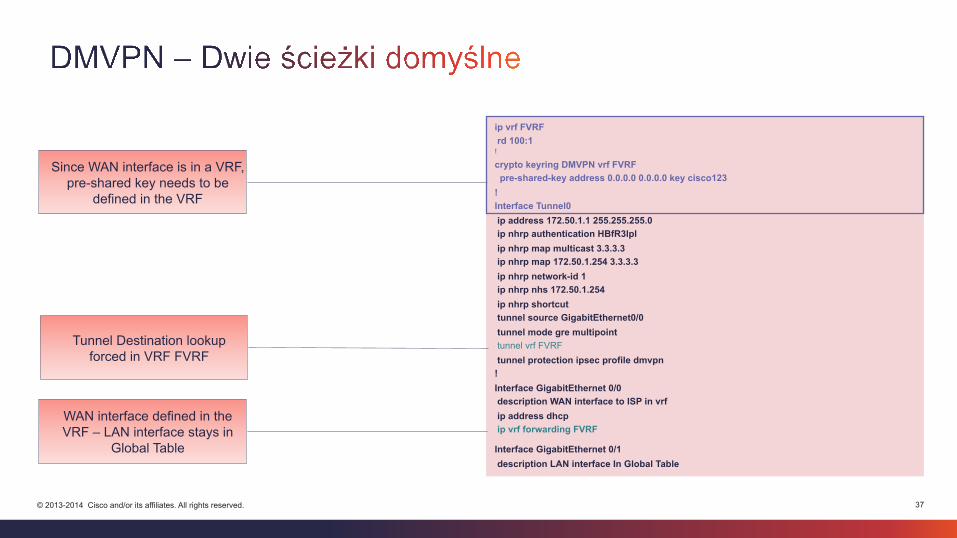
ip vrf FVRF rd 100:1 !
crypto keyring DMVPN vrf FVRF pre-shared-key address 0.0.0.0 0.0.0.0 key cisco123 ! Interface Tunnel0 ip address 172.50.1.1 255.255.255.0 ip nhrp authentication HBfR3lpl ip nhrp map multicast 3.3.3.3 ip nhrp map 172.50.1.254 3.3.3.3 ip nhrp network-id 1 ip nhrp nhs 172.50.1.254 ip nhrp shortcut tunnel source GigabitEthernet0/0 tunnel mode gre multipoint tunnel vrf FVRF tunnel protection ipsec profile dmvpn ! Interface GigabitEthernet 0/0 description WAN interface to ISP in vrf ip address dhcp ip vrf forwarding FVRF
Interface GigabitEthernet 0/1 description LAN interface In Global Table
Since WAN interface is in a VRF, pre-shared key needs to be
defined in the VRF
Tunnel Destination lookup forced in VRF FVRF
WAN interface defined in the VRF – LAN interface stays in
Global Table
38 © 2013-2014 Cisco and/or its affiliates. All rights reserved.
• IWAN CVD http://www.cisco.com/c/dam/en/us/td/docs/solutions/CVD/Jan2015/CVD-IWANDesignGuide-JAN15.pdf
• Introduction to IWAN (2015 Melbourne) https://www.ciscolive.com/online/connect/sessionDetail.ww?SESSION_ID=82772&backBtn=true
• Intelligent WAN (IWAN) Architecture (2015 Milan)https://www.ciscolive.com/online/connect/sessionDetail.ww?SESSION_ID=81978&backBtn=true
• IWAN and AVC Management with Cisco Prime Infrastructure (2015 Milan)https://www.ciscolive.com/online/connect/sessionDetail.ww?SESSION_ID=81876&backBtn=true
• Whitepapers, presentations, case studieshttp://www.cisco.com/c/en/us/solutions/enterprise-networks/intelligent-wan/index.html
• DMVPN http://www.cisco.com/c/en/us/td/docs/ios-xml/ios/sec_conn_dmvpn/configuration/15-s/sec-conn-dmvpn-15-s-book.html
• ISR and ASR AX Ordering Guide http://www.cisco.com/c/en/us/products/collateral/routers/3900-series-integrated-services-routers-isr/guide_c07-726864.html

Dziękuję J
Adam Śniegórski Systems Engineer, CCIE R&S Solutions & Innovation


![[1] Podstawy Budowy Tuneli - Kazimierz Furtak, Maciej Kędracki](https://img.pdfslide.net/doc/110x75/55cf8f58550346703b9b70db/1-podstawy-budowy-tuneli-kazimierz-furtak-maciej-kedracki.jpg)