Embed Size (px)
Citation preview
Intelligent BasesStandard, Relay, Isolator, Sounder, and Low-Frequency Sounder Bases
Intelligent/Addressable Devices
DN-60054:I • H-320
GeneralIntelligent FlashScan® and CLIP mounting bases and kits provide a variety of ways to install NOTIFIER detectors in any application. Intelligent detectors can be mounted in either flanged or flangeless bases depending on junction box selec-tion (see Junction Box Selection Guide). Across this product line, detectors plug in easily to the base with SEMS screws; and models employ various 12 to 24 AWG wire ranges.
Relay, isolator, and sounder bases can be used to meet local code requirements. Relay bases provide one Form-C contact relay for control of auxiliary functions such as door closure and elevator recall. Isolator bases allow loops to con-tinue to operate under fault conditions and automatically restore when the fault is removed. Sounder bases are avail-able in temporal and non-temporal pattern versions depend-ing on whether the signal is to be used for evacuation purposes. Low frequency sounder bases are UL listed for low frequency operation and comply with NFPA 72 requirements for sleeping spaces.
This datasheet discusses the following bases: B501(A), B200S(A), B200S-LF, B200SR(A), B200SR-LF, B210LP(A), B2241BI(A), B224RB(A), B200SCOA, mounting kits, and accessories.
SpecificationsDiameter:
• B501: 4.1" (104 mm).
• B224BI, B224RB, B210LP: 6.1" (155 mm).
• B200S, B200S-LF, B200SR, B200SR-LF, B200SCOA: 6.875" (17.46 cm).
Wire gauge:
• B224BI, B224RB: 14 to 24 AWG.
• B210LP, B501, B200S, B200S-LF, B200SR, B200SR-LF, B200SCOA: 12 to 24 AWG
Temperature range:
• B224BI, B224RB, B200S, B200S-LF, B200SR, B200SR-LF, B200SCOA: 32°F to 120°F (0°C to 49°C).
• B210LP, B501: -4°F to 150°F (-20°C to 66°C).
Humidity range: 10% to 93% RH, non-condensing.
System temperature and humidity ranges: This system meets NFPA requirements for operation at 0°C to 49°C (32°F to 120°F); and at a relative humidity (noncondensing) of 85% at 30°C (86°F) per NFPA, and 93% ± 2% at 32°C ± 2°C (89.6°F ± 1.1°F) per ULC. However, the useful life of the sys-tem’s standby batteries and the electronic components may be adversely affected by extreme temperature ranges and humidity. Therefore, it is recommended that this system and all peripherals be installed in an environment with a nominal room temperature of 15°C to 27°C (60°F to 80°F).
Electrical Ratings
FOR B200S, B200S-LF, B200SR, B200SR-LF, B200SCOA:External supply voltage: 16 to 33 VDC (VFWR)
Standby current:
• B200S: 500 µA maximum.
• B200S-LF, 550 µA maximum.
• B200SR: 500 µA maximum.
• B200SR-LF: 1 mA maximum.
Alarm current:
• B200S: 35 mA maximum at high-volume setting; 15 mA maximum at low-volume setting.
• B200S-LF, High-volume setting:
– 70 mA maximum @ 33.0 VDC. – 90 mA maximum @ 24.0 VDC. – 140 mA maximum @16.0 VDC.
• B200S-LF, Low-volume setting:
– 15 mA maximum @ 33.0 VDC. – 20 mA maximum @ 24.0 VDC. – 25 mA maximum @ 16.0 VDC.
• B200SR: 35 mA maximum.
• B200SR-LF:
– 65 mA maximum @ 33.0 VDC.
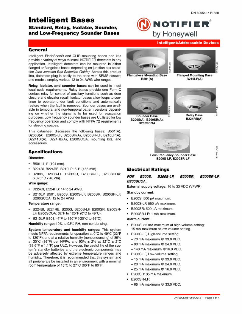
Flangeless Mounting Base B501(A)
Relay BaseB224RB(A)
Flanged Mounting Base B210LP(A)
Sounder Base B200S(A), B200SR(A),
B200SCOA
6005
4b5.
jpg
6005
4rb.
jpg
6005
4LP.
jpg
6005
4sr.j
pg
Low-Frequency Sounder Base B200S-LF, B200SR-LF B20
0S-L
F.jp
g
DN-60054:I • 2/3/2015 — Page 1 of 4
– 90 mA maximum @ 24.0 VDC. – 125 mA maximum @16.0 VDC.
• B200SCOA: 40mA Max. (DC), 70mA Max. (FWR)
SLC operating voltage: 15 to 32 VDC.
SLC standby current: See applicable sensor specification.
Sound output:
• B200S/B200S-LF, high-volume*: Greater than 85 dBA minimum.
• B200S/B200S-LF, low-volume*: Greater than 75 dBA mini-mum.
• B200SR*/B200SR-LF*: Greater than 85 dBA minimum.
• B200SCOA, high-volume**: Greater than 87 dBA mini-mum.
• B200SCOA, low-volume**: Greater than 85 dBA minimum*Measured in a UL reverberant room at 10 feet, 24 Volts (continuous tone)**Measured in a ULC anechoic room at 10 feet, 24 Volts continuous tone)
FOR B224RB, B224BI: Operating voltage: 15 to 32 VDC (powered by SLC).
Standby ratings: <500 µA maximum @ 24 VDC.
Set time (B224RB only): short delay 55 to 90 msec; long delay 6 to 9 seconds.
Reset time (B224RB only): 20 msec maximum.
Relay characteristics (B224RB only): two-coil latching relay; one Form-C contact; ratings (UL/CSA): 0.9 A @ 125 VAC, 0.9 A @ 110 VDC, and 3.0 A @ 30 VDC.
Product Line Information
INTELLIGENT BASESB501: Flangeless mounting base.
B501A: Flangeless mounting base, ULC Listed.
B501BP: Bulk pack of B501 (10).
B210LP: Flanged mounting base.
B210LPA: Flanged mounting base, ULC listed
B210LPBP: Bulk pack of B210LP (10).
B200S: Intelligent addressable sounder base capable of pro-ducing sound output in high or low volume with ANSI Tempo-ral 3, ANSI Temporal 4, continuous tone, marching tone, and custom tone. Uses FlashScan protocol. Only compatible with the NFS-320, NFS2-640 and NFS2-3030 operating version with version 15.0 or higher panel firmware.
B200SA: ULC-listed version of B200S.
B200SCOA: ULC-listed version of B200S with CO detector markings in English/French (required in Canada for ULC applications with FCO-851A).
B200S-LF: Low Frequency version of the B200S; produces a fundamental frequency of 520 Hz +/- 10% with a square wave or its equivalent; designed to meet the NFPA 72 sleep-ing space requirement.
B200SR: Intelligent sounder base capable of producing sound output with ANSI Temporal 3 or continuous tone.
B200SRA: ULC-listed version of B200SR.
B200SR-LF: Low Frequency version of the B200SR; pro-duces a fundamental frequency of 520 Hz +/- 10% with a square wave or its equivalent; designed to meet the NFPA 72 sleeping space requirement.
B224RB: Relay base.
B224RBA: Relay base, ULC Listed.
B224BI: Isolator base.
B224BIA: Isolator base, ULC Listed.
MOUNTING KITS AND ACCESSORIESSMB600: Surface mounting kit, flanged.
F110: Retrofit flange for converting high-profile bases to low-profile.
F110BP: Bulk pack of F110 (10).
F210: Accessory flange ring for B210LP(A) base (new design). 6-inch diameter.
F210BP: Bulk pack of F210 (10).
RA100Z: Remote LED annunciator.
RA100ZA: Remote LED annunciator, ULC Listed.
M02-04-00: Detector test magnet.
M02-09-00: Test magnet with telescoping handle.
XR2B: Detector removal tool for current heads (T55-127-010 included).
XR2: Detector Remove Tool for use with low profile detector heads, and FSL-751.
XP-4: Extension pole for XR2/B (5 to 15 ft/1.524 to 4.572 m).
T55-127-010: Detector removal head.
BCK-200B: Black detector kit, package of 10 (for use with photo and ion detectors).
WCK-200B: White detector kit, package of 10 (for use with photo and ion detectors).
Agency Listings and ApprovalsThe listings and approvals below apply to intelligent bases as noted. In some cases, certain modules or applications may not be listed by certain approval agencies, or listing may be in process. Consult factory for latest listing status.
• UL Listed: S911, S1115.
• ULC Listed: S911, S1115.
• FM Approved.
• MEA: 22-95-E, 205-94-E Vol. 2; 257-06-E
• CSFM: 7300-1653:0126, 7135-1653:0213, 7300-1653:0109
Page 2 of 4 — DN-60054:I • 2/3/2015

Junction Box Selection Guide
Base Models Single Gang 3.5" Oct. 4.0" Oct. 4.0" Sq.
4.0" Sq.with 3.0" mud ring
50 mm 60 mm 70 mm 75 mm
B200S, B200S-LF, B200SR, B200SR-LF, B200SCOA
Yes Yes Yes Yes Yes No No No No
B501 No Yes No No Yes Yes Yes Yes No
B210LP Yes Yes Yes Yes Yes No No No No
B224RB No Yes Yes Yes No No Yes Yes Yes
B224BI No Yes Yes Yes No No No Yes Yes
NOTE: Box depth contingent on base and wire size.Refer to National Electric Code or applicable local codes for appropriate recommendations.
DN-60054:I • 2/3/2015 — Page 3 of 4

FlashScan®, NOTIFIER® and System Sensor® are registered trademarksof Honeywell International Inc.©2015 by Honeywell International Inc. All rights reserved. Unauthorized use of this document is strictly prohibited.
Page 4 of 4 — DN-60054:I • 2/3/2015
This document is not intended to be used for installation purposes. We try to keep our product information up-to-date and accurate.
We cannot cover all specific applications or anticipate all requirements. All specifications are subject to change without notice.
For more information, contact Notifier. Phone: (203) 484-7161, FAX: (203) 484-7118.www.notifier.com

FSP-851(A) SeriesIntelligent Plug-In PhotoelectricSmoke Detectors with FlashScan®
Intelligent/Addressable Devices
DN-6935:E • H-202
GeneralNotifier FSP-851(A) Series intelligent plug-in smoke detec-tors with integral communication provide features that sur-pass conventional detectors. Detector sensitivity can beprogrammed in the control panel software. Sensitivity is con-tinuously monitored and reported to the panel. Point ID capa-bility allows each detector’s address to be set with rotary,decimal address switches, providing exact detector locationfor selective maintenance when chamber contaminationreaches an unacceptable level. The FSP-851(A) photoelec-tric detector’s unique optical sensing chamber is engineeredto sense smoke produced by a wide range of combustionsources. Dual electronic thermistors add 135°F (57°C) fixed-temperature thermal sensing on the FSP-851T(A). The FSP-851R(A) is a remote test capable detector for use withDNR(A)/DNRW duct detector housings. FSP-851(A) seriesdetectors are compatible with Notifier Onyx and CLIP seriesFire Alarm Control Panels (FACPs).
FlashScan® (U.S. Patent 5,539,389) is a communicationprotocol developed by Notifier that greatly increases thespeed of communication between analog intelligent devices.Intelligent devices communicate in a grouped fashion. If oneof the devices in the group has new information, the panel’sCPU stops the group poll and concentrates on single points.The net effect is response speed greater than five times thatof earlier designs.
Features• Sleek, low-profile design.
• Addressable-analog communication.
• Stable communication technique with noise immunity.
• Low standby current.
• Two-wire SLC connection.
• Compatible with FlashScan® and CLIP protocol systems.
• Rotary, decimal addressing (1-99 on CLIP systems, 1-159on FlashScan systems).
• Optional remote, single-gang LED accessory.
• Dual LED design provides 360° viewing angle.
• Visible bi-color LEDs blink green every time the detector isaddressed, and illuminate steady red on alarm (FlashS-can systems only).
• Remote test feature from the panel.
• Walk test with address display (an address on 121 willblink the detector LED: 12-[pause]-1(FlashScan systemsonly).
• Built-in functional test switch activated by external magnet.
• Built-in tamper-resistant feature.
• Sealed against back pressure.
• Constructed of off-white fire-resistant plastic, designed tocommercial standards, and offers an attractive appear-ance.
• 94-5V plastic flammability rating.
• SEMS screws for wiring of the separate base.
• Optional relay, isolator, and sounder bases.
SpecificationsSensitivity: 0.5% to 2.35% per foot obscuration
Size: 2.1" (5.3 cm) high; base determines diameter.
– B210LP(A): 6.1" (15.5 cm) diameter.
– B501(A): 4.1" (10.4 cm) diameter.
– B200S(A): 6.875" (17.46 cm) diameter.
– B200SR(A): 6.875" (17.46 cm) diameter.
– B224RB(A): 6.2" (15.748 cm) diameter.
– B224BI(A): 6.2" (15.748 cm) diameter.
Shipping Weight: 5.2oz. (147g).
Operating Temperature range: FSP-851(A), 0°C to 49°C(32°F to 120°F). FSP-851T(A), 0°C to 38°C (32°F to 100°F).Low temperature signal for FSP-851T(A) at 45°F +/- 10°F(7.22°C +/- 5.54°C). FSP-851R(A) installed in a DNR(A)/DNRW, -20°C to 70°C (-4°F to 158°F).
UL/ULC Listed Velocity Range: 0-4000 ft/min. (1219.2 m/min.), suitable for installation in ducts.
Relative Humidity: 10%-93% noncondensing.
Thermal Ratings: Fixed-temperature setpoint 135°F (57°C).
DETECTOR SPACING AND APPLICATIONS
Notifier recommends spacing detectors in compliance withNFPA 72. In low airflow applications with smooth ceiling,space detectors 30 feet (9.144m) for ceiling heights 10 feet(3.148m) and higher. For specific information regardingdetector spacing, placement, and special applications refer toNFPA 72. System Smoke Detector Application Guide, docu-ment A05-1003, is available at systemsensor.com
ELECTRICAL SPECIFICATIONS
Voltage Range: 15-32 volts DC peak.
Standby Current (max. avg.): 300µA @ 24VDC (one com-munication every five seconds with LED enabled).
LED Current (max.): 6.5mA @ 24 VDC (“ON”).
FSP-851(A) in B210LP(A) Base B210-2951.jpg
DN-6935:E • 2/11/2015 — Page 1 of 2

NOTIFIER® is a registered trademark of Honeywell International Inc.©2015 by Honeywell International Inc. All rights reserved. Unauthorized useof this document is strictly prohibited.
InstallationFSP-851(A) plug-in detectors use a separate base to simplifyinstallation, service, and maintenance. A special tool allowsmaintenance personnel to plug in and remove detectors with-out using a ladder.
Mount base (all base types) on an electrical backbox which isat least 1.5" (3.81 cm) deep. For a chart of compatible junc-tion boxes, see DN-60054.
NOTE: 1) Because of inherent supervision provided by the SLCloop, end-of-line resistors are not required. Wiring “T-taps” orbranches are permitted for Style 4 (Class “B”) wiring. 2) Whenusing relay or sounder bases, consult the ISO-X(A) installationsheet I56-1380 for device limitations between isolator modulesand isolator bases.
Agency Listings and ApprovalsThese listings and approvals apply to the modules specifiedin this document. In some cases, certain modules or applica-tions may not be listed by certain approval agencies, or listingmay be in process. Consult factory for latest listing status.
• UL Listed: S1115.
• ULC Listed: S1115 (FSP-851A, FSP-851RA, FSP-851TA).
• MEA Listed: 225-02-E .
• FM Approved.
• CSFM: 7272-0028:0206 .
• Maryland State Fire Marshal: Permit # 2122 .
• BSMI: CI313066760036.
• CCCF: Certif. # 2004081801000017 (FSP-851T)Certif. # 2004081801000016 (FSP-851).
• U.S. Coast Guard: 161.002/42/1 (NFS-640); 161.002/50/0 (NFS2-640/NFS-320/NFS-320C, excluding B210LP(A)).
• Lloyd’s Register: 11/600013 (NFS2-640/NFS-320/NFS-320C, excluding B210LP(A)).
Product Line InformationNOTE: “A” suffix indicates ULC Listed model.
FSP-851: Low-profile intelligent photoelectric sensor. Mustbe mounted to one of the bases listed below.
FSP-851A: Same as FSP-851 but with ULC listing.
FSP-851T: Same as FSP-851 but includes a built-in 135°F(57°C) fixed-temperature thermal device.
FSP-851TA: Same as FSP-851T but with ULC listing.
FSP-851R: Low-profile intelligent photoelectric sensor,remote test capable. For use with DNRA/DNRW.
FSP-851RA: Same as FSP-851R but with ULC listing. Foruse with DNRA.
INTELLIGENT BASES
NOTE: “A” suffix indicates ULC Listed model.
NOTE: For details on intelligent bases, see DN-60054.
B210LP(A): Standard U.S. flanged low-profile mountingbase.
B210LPBP: Bulk pack of B210LP; package contains 10.
B501(A): Standard European flangeless mounting base.
B501BP: Bulk pack of B501; package contains 10.
B200S(A): Intelligent, programmable sounder base capableof producing sound output in high or low volume with ANSITemporal 3, ANSI Temporal 4, continuous tone, marchingtone, and custom tone.
B200SR(A): Intelligent sounder base capable of producingsound output with ANSI Temporal 3 or continuous tone.Replaces B501BH series bases in retrofit applications.
B224RB(A): Plug-in System Sensor relay base. Screw ter-minals: up to 14 AWG (2.0 mm²). Relay type: Form-C. Rating:2.0 A @ 30 VDC resistive; 0.3 A @ 110 VDC inductive; 1.0 A@ 30 VDC inductive.
B224BI(A): Plug-in System Sensor isolator detector base.Maximum 25 devices between isolator bases.
ACCESSORIES
F110: Retrofit flange to convert B210LP(A) to match theB710LP(A) profile, or to convert older high-profile bases tolow-profile.
F110BP: Bulk pack of F110; package contains 15.
F210: Replacement flange for B210LP(A) base.
RA100Z(A): Remote LED annunciator. 3 – 32 VDC. Mountsto a U.S. single-gang electrical box. For use with B501(A)and B210LP(A) bases only.
SMB600: Surface mounting kit
M02-04-00: Test magnet.
M02-09-00: Test magnet with telescoping handle.
XR2B: Detector removal tool. Allows installation and/orremoval of detector heads from bases in high ceiling applica-tions.
XP-4: Extension pole for XR2B. Comes in three 5-foot (1.524m) sections.
T55-127-010: Detector removal tool without pole.
BCK-200B: Black detector covers for use with FSP-851(A)only; box of 10.
WCK-200B: White detector covers for use with FSP-851(A)only; box of 10.
Page 2 of 2 — DN-6935:E • 2/11/2015
This document is not intended to be used for installation purposes. We try to keep our product information up-to-date and accurate.
We cannot cover all specific applications or anticipate all requirements. All specifications are subject to change without notice.
For more information, contact Notifier. Phone: (203) 484-7161, FAX: (203) 484-7118.www.notifier.com

FlashScan (U.S. Patent 5,539,389) is a communication pro-tocol that greatly enhances the speed of communicationbetween analog intelligent devices. Intelligent devices com-municate in a grouped fashion. If one of the devices withinthe group has new information, the panel’s CPU stops thegroup poll and concentrates on single points. The net effectis response speed greater than five times that of earlierdesigns.
Technical InformationOperating Temperature:. . . . . 32 °F to 120 °F (0 °C to 49 °C)UL Listed Velocity Range: . . 0 – 4000 fpm (0 – 20.32 m/sec)Relative Humidity: . . . . . . . . . . . 10% to 93% noncondensingVoltage Range: . . . . . . . . . . . . . . . . . . 15 – 32 volts DC peakStandby Current: . 250 µA @ 24 VDC (w/o communication);
360 µA @ 24 VDC (one communicationevery 5 seconds with LED enabled)
LED Current (max.): . . . . . . . . . . . . . 6.5 mA @ 24 VDC (ON)Diameter:. . . . . . . . . . . . . . . . . . . . . . . . . . . . 4.1 in. (104 mm)Height: . . . . . . . . . . . . . . . . . . . . . . . . . . . . . . 1.69 in. (43 mm)Bases Available:
B710LP:. . . . . . . . . . . . . . . . . . . 6.1 in. (155 mm) diameterB501: . . . . . . . . . . . . . . . . . . . . . 4.1 in. (104 mm) diameterB501BH: . . . . . . . . . . . . . . . Sounder base with B501baseB224RB: . . . . 6.2 in. dia. x 1.2 in. high (157 mm x 30 mm)
Relay type: . . . . . . . . . . . . . . . . . . . . . . . . . . . . . Form-CRating: . . . . . . . . . . . . . . . . . . 2.0 A @ 30 VDC resistive
0.3 A @ 110 VDC inductive1.0 A @ 30 VDC inductive
Screw terminals: . . . . . . . . . Up to 14 AWG (2.00 mm2)B224BI: . . . . . 6.2 in. dia. x 1.2 in. high (157 mm x 30 mm)
Maximum:. . . . . . . . 25 devices between isolator bases
AutoPulse
Detection and Control Components
FSP-851 Intelligent PhotoelectricSmoke Detector
ANSUL®
Features
• Sleek low profile design
• Analog-addressable communication
• Stable communication technique with noise immunity
• Low standby current
• Rotary 01 to 159* address switches
• Optional remote, single-gang LED accessory (RA400Z)
• Dual LED design provides 360° viewing angle
• Visible bicolor LEDs blink green every time the detector isaddressed; illuminate steady red on alarm
• Walk test with address display (an address of 91 will blinkthe detector LED: 9-(pause)-1) (FlashScan® systems only)
• Built-in functional test switch activated by external magnet
• Optional relay, isolator, or sounder bases
• Listed to UL 268
• FlashScan® communication protocol
Applications
The FSP-851 is an analog, addressable, low-profile smokedetector designed for the AUTOPULSE® IQ-301, IQ-396X,and IQ-636X Fire Alarm Control Units.
The addressability of the FSP-851 detector enables the con-trol unit to provide firefighters with a pinpoint description ofwhere the fire is located. The control unit is capable of notonly knowing the detector’s location but also exactly howmuch smoke is in the chamber of the detector. The detectormay be set for different sensitivity settings appropriate to theenvironment of its location.
Analog devices continually send obscuration values to theAUTOPULSE control unit. These values may be gathered soas to allow the control unit to determine if a detector hasaccumulated an excessive amount of dirt or dust. A “main-tenance” required indication allows the installer to clean thesmoke detector before an unwanted false alarm occurs.
Description
The FSP-851 Intelligent Photoelectric Sensor’s unique opti-cal sensing chamber is designed with superior signal tonoise ratio. The optical chamber is engineered to sense thepresence of smoke produced by a wide range of combus-tion sources. The FSP-851 can be used to replace theSDX-751 or FSP-751 in existing systems.
* 01-99 with AUTOPULSE IQ-301 and IQ-396X
006878
FSP-851 with B710LP Base
3-162-1-06
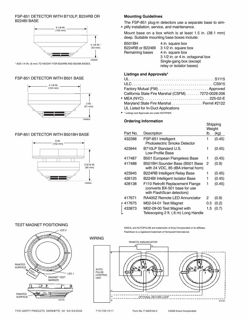
Mounting Guidelines
The FSP-851 plug-in detectors use a separate base to sim-plify installation, service, and maintenance.
Mount base on a box which is at least 1.5 in. (38.1 mm)deep. Suitable mounting base boxes include:
B501BH 4 in. square boxB224RB or B224BI 3 1/2 in. square boxRemaining bases 4 in. square box
3 1/2 in. or 4 in. octagonal boxSingle-gang box (exceptrelay or isolator bases)
Listings and Approvals*UL . . . . . . . . . . . . . . . . . . . . . . . . . . . . . . . . . . . . . . . . . . S1115ULC . . . . . . . . . . . . . . . . . . . . . . . . . . . . . . . . . . . . . . . . CS915Factory Mutual (FM). . . . . . . . . . . . . . . . . . . . . . . . . ApprovedCalifornia State Fire Marshal (CSFM). . . . . . . 7272-0028:206MEA (NYC) . . . . . . . . . . . . . . . . . . . . . . . . . . . . . . . . 225-02-EMaryland State Fire Marshal . . . . . . . . . . . . . . . Permit #2122UL Listed for In-Duct Applications* Listings and Approvals are under NOTIFIER.
Ordering InformationShippingWeight
Part No. Description lb. (kg)
432288 FSP-851 Intelligent 1 (0.45)Photoelectric Smoke Detector
423944 B710LP Standard U.S. 1 (0.45)Low-Profile Base
417487 B501 European Flangeless Base 1 (0.45)417488 B501BH Sounder Base (B501 Base 2 (0.9)
with 24 VDC, 85 dBA internal horn)423945 B224RB Intelligent Relay Base 1 (0.45)426125 B224BI Intelligent Isolator Base 1 (0.45)428138 F110 Retrofit Replacement Flange 1 (0.45)
(converts BX-501 base for usewith FlashScan detectors)
417671 RA400Z Remote LED Annunciator 2 (0.9)417675 M02-04-01 Test Magnet 0.5 (0.2)433873 M02-09-00 Test Magnet with 1.5 (0.7)
Telescoping 2 ft. (.6 m) Long Handle
TYCO SAFETY PRODUCTS, MARINETTE, WI 54143-2542 715-735-7411 Form No. F-2003164-2 ©2006 Ansul Incorporated
ANSUL and AUTOPULSE are trademarks of Ansul Incorporated or its affiliates.
FlashScan is a registered trademark of Honeywell International.
FSP-851 DETECTOR WITH B501BH BASE
006869c
6 IN.(152 mm)
3 9/16 IN.(90 mm)
TEST MAGNET POSITIONING
LED 1
LED 2
MAGNET TESTMARKER
PAINTEDSURFACE
PAINTEDSURFACE
TESTMAGNET
TESTMAGNET
004763
WIRINGREMOTE ANNUNCIATOR
AUTO-PULSECONTROLUNIT
OPTIONAL RETURN LOOP
004760
FSP-851 DETECTOR WITH B501 BASE
006869a
FSP-851 DETECTOR WITH B710LP, B224RB ORB224BI BASE
006869b
* ADD 1/4 IN. (6 mm) TO HEIGHT FOR B224RB AND B224BI BASES.
4 1/8 IN.(104 mm)
6 1/8 IN.(155 mm)
2 1/8 IN.*(53 mm)
2 IN.(51 mm)
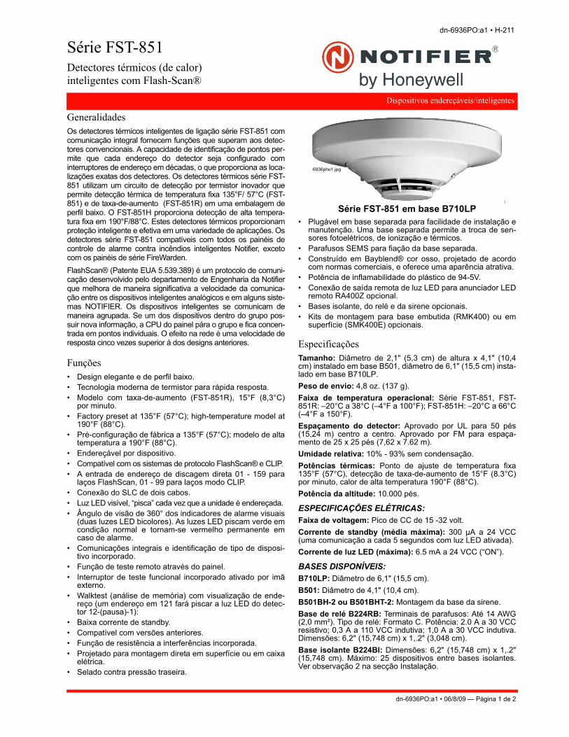
Série FST-851Detectores térmicos (de calor)inteligentes com Flash-Scan®
Dispositivos endereçáveis/inteligentes
dn-6936PO:a1 • H-211
GeneralidadesOs detectores térmicos inteligentes de ligação série FST-851 comcomunicação integral fornecem funções que superam aos detec-tores convencionais. A capacidade de identificação de pontos per-mite que cada endereço do detector seja configurado cominterruptores de endereço em décadas, o que proporciona as loca-lizações exatas dos detectores. Os detectores térmicos série FST-851 utilizam um circuito de detecção por termistor inovador quepermite detecção térmica de temperatura fixa 135°F/ 57°C (FST-851) e de taxa-de-aumento (FST-851R) em uma embalagem deperfil baixo. O FST-851H proporciona detecção de alta tempera-tura fixa em 190°F/88°C. Estes detectores térmicos proporcionamproteção inteligente e efetiva em uma variedade de aplicações. Osdetectores série FST-851 compatíveis com todos os painéis decontrole de alarme contra incêndios inteligentes Notifier, excetocom os painéis de série FireWarden.
FlashScan® (Patente EUA 5.539.389) é um protocolo de comuni-cação desenvolvido pelo departamento de Engenharia da Notifierque melhora de maneira significativa a velocidade da comunica-ção entre os dispositivos inteligentes analógicos e em alguns siste-mas NOTIFIER. Os dispositivos inteligentes se comunicam demaneira agrupada. Se um dos dispositivos dentro do grupo pos-suir nova informação, a CPU do painel pára o grupo e fica concen-trada em pontos individuais. O efeito na rede é uma velocidade deresposta cinco vezes superior à dos designs anteriores.
Funções • Design elegante e de perfil baixo. • Tecnologia moderna de termistor para rápida resposta. • Modelo com taxa-de-aumento (FST-851R), 15°F (8,3°C)
por minuto. • Factory preset at 135°F (57°C); high-temperature model at
190°F (88°C).• Pré-configuração de fábrica a 135°F (57°C); modelo de alta
temperatura a 190°F (88°C). • Endereçável por dispositivo. • Compatível com os sistemas de protocolo FlashScan® e CLIP. • A entrada de endereço de discagem direta 01 - 159 para
laços FlashScan, 01 - 99 para laços modo CLIP. • Conexão do SLC de dois cabos. • Luz LED visível, “pisca” cada vez que a unidade é endereçada. • Ângulo de visão de 360° dos indicadores de alarme visuais
(duas luzes LED bicolores). As luzes LED piscam verde emcondição normal e tornam-se vermelho permanente emcaso de alarme.
• Comunicações integrais e identificação de tipo de disposi-tivo incorporado.
• Função de teste remoto através do painel. • Interruptor de teste funcional incorporado ativado por imã
externo. • Walktest (análise de memória) com visualização de ende-
reço (um endereço em 121 fará piscar a luz LED do detec-tor 12-(pausa)-1):
• Baixa corrente de standby. • Compatível com versões anteriores. • Função de resistência a interferências incorporada. • Projetado para montagem direta em superfície ou em caixa
elétrica. • Selado contra pressão traseira.
• Plugável em base separada para facilidade de instalação emanutenção. Uma base separada permite a troca de sen-sores fotoelétricos, de ionização e térmicos.
• Parafusos SEMS para fiação da base separada. • Construído em Bayblend® cor osso, projetado de acordo
com normas comerciais, e oferece uma aparência atrativa. • Potência de inflamabilidade do plástico de 94-5V. • Conexão de saída remota de luz LED para anunciador LED
remoto RA400Z opcional. • Bases isolante, do relé e da sirene opcionais. • Kits de montagem para base embutida (RMK400) ou em
superfície (SMK400E) opcionais.
Especificações Tamanho: Diâmetro de 2,1" (5,3 cm) de altura x 4,1" (10,4cm) instalado em base B501, diâmetro de 6,1" (15,5 cm) insta-lado em base B710LP.
Peso de envio: 4,8 oz. (137 g).
Faixa de temperatura operacional: Série FST-851, FST-851R: –20°C a 38°C (–4°F a 100°F); FST-851H: –20°C a 66°C(–4°F a 150°F).
Espaçamento do detector: Aprovado por UL para 50 pés(15,24 m) centro a centro. Aprovado por FM para espaça-mento de 25 x 25 pés (7,62 x 7.62 m).
Umidade relativa: 10% - 93% sem condensação.
Potências térmicas: Ponto de ajuste de temperatura fixa135°F (57°C), detecção de taxa-de-aumento de 15°F (8.3°C)por minuto, calor de alta temperatura 190°F (88°C).
Potência da altitude: 10.000 pés.
ESPECIFICAÇÕES ELÉTRICAS:
Faixa de voltagem: Pico de CC de 15 -32 volt.
Corrente de standby (média máxima): 300 µA a 24 VCC(uma comunicação a cada 5 segundos com luz LED ativada).
Corrente de luz LED (máxima): 6.5 mA a 24 VCC (“ON”).
BASES DISPONÍVEIS:
B710LP: Diâmetro de 6,1" (15,5 cm).
B501: Diâmetro de 4,1" (10,4 cm).
B501BH-2 ou B501BHT-2: Montagem da base da sirene.
Base de relé B224RB: Terminais de parafusos: Até 14 AWG(2,0 mm²). Tipo de relé: Formato C. Potência: 2.0 A a 30 VCCresistivo; 0,3 A a 110 VCC indutiva; 1,0 A a 30 VCC indutiva.Dimensões: 6,2" (15,748 cm) x 1,.2" (3,048 cm).
Base isolante B224BI: Dimensões: 6,2" (15,748 cm) x 1,.2"(15,748 cm). Máximo: 25 dispositivos entre bases isolantes.Ver observação 2 na secção Instalação.
Série FST-851 em base B710LP
6936pho1.jpg
dn-6936PO:a1 • 06/8/09 — Página 1 de 2
Notifier® e FlashScan® são uma marca registrada da Honeywell International Inc. Bay-blend® é uma marca registrada da Bayer Corp. ©2011 by Honeywell International Inc. Todos os direitos reservados. É proibido o usonão autorizado deste documento.
Aplicações Utilize detectores térmicos para proteção da propriedade.Para obter mais informações, acesse systemsensor.com eveja o manual I56-407-00, Manual de aplicações para detecto-res de fumaça de sistemas, que proporciona informaçõesdetalhadas sobre o espaçamento e localização do detector.Zoneamento, fiação e aplicações especiais.
Instalação Os detectores térmicos inteligentes plugáveis da série FSTutilizam uma base separada para simplificar a instalação, ser-viço e manutenção. As instruções sobre a instalação sãoenviadas com cada detector.
Base de montagem (todo tipos de bases) em um caixa deconexões elétrica com uma profundidade de, pelo menos, 1,5"(3,81 cm). As caixas adequadas incluem:
• Caixa quadrada de 4,0" (10,16 cm).
• Caixa octogonal 3,5" (8,89 cm) ou de 4,0" (10,16 cm).
• Caixa de saída única (exceto base isolante ou de relé).
• Com base B501BH-2 ou B501BHT-2, utilize uma caixaquadrada de 4,0" (10,16 cm).
• Com base B224RB ou B224BI utilize uma caixa octogonalde 3,5" (8,89 cm) ou de 4,0" (10,16cm) ou uma caixa qua-drada de 4,0" (10,16cm).
OBSERVAÇÃO: 1) Devido à supervisão inerente fornecida pelo laçodo SLC, os resistores de final de linha não são necessários. A fiaçãocom conexões tipo “T-taps” ou suas ramificações estão permitidas paraa fiação estilo 4 (Classe B). 2) Ao utilizar as bases da sirene ou do relé,consulte a folha de dados DN-2243 (ISO-X) para limitações do disposi-tivo entre os módulos isolantes e as bases isolantes.
Aprovações e listados das agências de controle Estes listados e aprovações se aplicam aos módulos especifica-dos neste documento. Em alguns casos, é possível que algunsmódulos ou aplicativos não estejam listados por algumas agênciasde aprovação ou os listados podem estar ainda em andamento.Consulte a fábrica para o estado do último listado.
• Listado em UL: S747
• Listado em ULC: S6978
• Listado em MEA: 383-02-E
• Aprovado por FM
• CSFM: 7270-0028:196
• BSMI: CI313066760025
• CCCF: Certif. # 2004081801000018
• Guarda Costeira dos EUA: 161.002/23/3 (AFP-200);161.002/27/3 (AFP1010/AM2020); 161.002/42/1 (NFS-640)
• Lloyd’s Register: 03/60011
Informação da linha de produtos O sufixo “A” indica um modelo listado em ULC.
FST-851: Detector térmico inteligente. Deve ser montado auma das bases listadas abaixo.
FST-851A: O mesmo que o FST-851, mas listado em ULC.
FST-851R: Detector térmico inteligente com função de taxa-de-aumento.
FST-851RA: O mesmo que o FST-851R, mas listado em ULC.
FST-851H: Detector térmico inteligente de alta temperatura.
FST-851HA: O mesmo que o FST-851H, mas listado em ULC.
BASES:
B710LP: Base de perfil baixo padrão segundo a norma dosEUA.
B710LPBP: Base de perfil baixo padrão segundo a norma dosEUA, pacote de 10 unidades.
B710LP: Base de perfil baixo padrão segundo a norma dosEUA
B710LP(A): Base de perfil baixo padrão segundo a norma dosEUA.
B501BP: Base sem flange padrão segundo a norma européia,pacote de 10 unidades.
B501: Base sem flange padrão segundo a norma européia.
B501(A): Base sem flange padrão segundo a norma européia,listado em ULC.
BH501BH-2: Base de sirene, inclui base B501 acima.
BH501BHT-2: A mesma que a B501BH-2, mas inclui sirenetemporal.
BH501BHA: Base de sirene, inclui base B501 acima.
BH501BHTA: A mesma que a BH501BHA, mas inclui sirene tem-poral.
B224BI(A): Base isolante inteligente. Isola o SLC dos curtos-circuitos do laço.
ACESSÓRIOS:
F110: Flange de substituição de atualização para bases anti-gas de perfil alto. Converte as bases para seu uso com detec-tores FlashScan®.
RA400Z(A): Anunciador LED remoto. 3 - 32 VCC. Compatívelcom a caixa elétrica de saída única. Compatível somente combases B710LPBP(A) e B501(A).
SMK400E: Kit de montagem em superfície para entrada deconduto de fiação em superfície. Somente para uso com baseB501(A).
RMK400: Kit de montagem embutida. Somente para uso combase B501(A).
SMB600: Kit de montagem em superfície para uso comB710LPBP(A).
BCK-200B: Cobertas pretas para detectores, caixa de 10 uni-dades.
M02-04-00: Imã de teste.
M02-09-00: Imã de teste com cabo telescópico.
XR2B: Ferramenta para remoção do detector. Permite a insta-lação e/ou remoção dos cabeçalhos dos detectores sérieFlashScan® da base em instalações em tetos altos.
T55-127-010: Ferramenta de remoção do detector sem poste.
XP-4: Poste de extensão para XR2B. Oferece três seções de5 pés.
Página 2 de 2 — dn-6936PO:a1 • 06/8/09
Este documento não foi elaborado com o fim da instalação. Tentamos manter as informações do produto atualizadas e precisas.
Não podemos abranger todas as aplicações específicas nem prever todos os requerimentos. Todas as especificações estão sujeitas a modificações sem aviso prévio.
Para mais informações, entre em contato com a Notifier. Telefone: (203) 484-7161, FAX: (203) 484-7118.www.notifier.com
Fabricado nos EUA.

NFS2-3030Intelligent AddressableFire Alarm System
Intelligent Fire Alarm Control Panels
DN-7070:N • A-10
NFS2-3030 (left) and NFS2-3030 with DVC audio option (right)
7070covg.jpg
General The NFS2-3030 is an intelligent Fire Alarm Control Panel(FACP) designed for medium- to large-scale facilities. Fireemergency detection and evacuation are extremely critical tolife safety, and the NFS2-3030 is ideally suited for these appli-cations. The NFS2-3030 is part of the ONYX® Series of prod-ucts from NOTIFIER. The NFS2-3030 is ideal for virtually anyapplication because it features a modular design that is config-ured per project requirements. With one to ten Signaling LineCircuits (SLCs), the NFS2-3030 supports up to 3,180 intelli-gent addressable devices.
Information is critical to fire evacuation personnel, and theNFS2-3030’s large 640-character Liquid Crystal Display (LCD)presents vital information to operators concerning a fire situa-tion, fire progression, and evacuation details.
A host of other options are available, including single- or multi-channel voice; firefighter’s telephone; LED, LCD, or PC-basedgraphic annunciators; networking; advanced detection prod-ucts for challenging environments; wireless fire protection; andmany additional options.
Features• Certified for seismic applications when used with the appro-
priate seismic mounting kit.
• Approved for Marine applications when a marine-listed ver-sion is used with marine-listed compatible equipment. SeeDN-60688.
• Complies with UL 2572 Mass Notification Systems (NFS2-3030 version 20 or higher).
• One to ten isolated intelligent Signaling Line Circuits (SLC)Style 4, 6 or 7.
• Wireless fire protection using SWIFT Smart Wireless Inte-grated Fire Technology. See DN-60820.
• Up to 159 detectors and 159 modules per SLC; 318 devicesper loop/3,180 per FACP or network node.
– Detectors can be any mix of ion, photo, thermal, or multi-sensor; wireless detectors are available for use with theFWSG.
– Modules include addressable pull stations, normally opencontact devices, two-wire smoke detectors, notification, orrelay; wireless modules are available for use with theFWSG.
• Large 16 line, 640 character LCD backlit display or usedisplay-less as a network node.
• Network options:
– High-speed network for up to 200 nodes (NFS2-3030,NFS2-640, NFS-320(C), NFS-320SYS, NCA-2, DVC-EM,ONYXWorks, NFS-3030, NFS-640, and NCA).
– Standard network for up to 103 nodes (NFS2-3030,NFS2-640, NFS-320(C), NFS-320SYS, NCA-2, DVC-EM,ONYXWorks, NCS, NFS-3030, NFS-640, NCA, AFP-200,AFP-300/400, AFP-1010, and AM2020). Up to 54 nodeswhen DVC-EM is used in network paging.
• Built-in Alarm, Trouble, Security, and Supervisory relays.
• VeriFire® Tools online/offline program option.
• With built-in Degraded Mode operation, the system is capa-ble of general alarm if a fire alarm condition is present evenif the central processing unit (CPU) fails.
• Weekly Occupancy Schedules allow changing sensitivity bytime of day and day of week.
• EIA-485 annunciators, including custom graphics.
• History file with 4000-event capacity in nonvolatile memory,plus separate 1000-event alarm-only file.
• Advanced history filters allow sorting by event, time, date,or address.
• Alarm Verification selection per point, with automaticcounter.
• Autoprogramming and Walk Test reports.
• Multiple central station communication options:
– Standard UDACT
– Internet
– Internet/GSM
• Positive Alarm Sequence (PAS) Presignal.
• Silence Inhibit and Auto Silence timer options.
• Field-programmable on panel or on PC, with VeriFire Toolsprogram, also check, compare.
• Non-alarm points for lower priority functions.
• Remote ACK/Signal Silence/System Reset/Drill via monitormodules.
• Up to 1000 powerful Boolean logic equations.
• Supports SCS Series smoke control system in both HVACand FSCS modes.
• FM6320 approved Gas Detection System with FMM-4-20module and any FM listed gas detector.
• EIA-232 printer port.
• EIA-485 annunciator port.
DN-7070:N • 01/25/2016 — Page 1 of 8
640-CHARACTER DISPLAY FEATURES
• Backlit, 640-character display.
• Program keypad: full QWERTY keypad.
• Up to nine users, each with a password and selectableaccess levels.
• 11 LED indicators: Power; Fire Alarm; Pre-Alarm; Secu-rity; Supervisory; System Trouble; Other Event; SignalsSilenced; Point Disabled; CPU Failure; Controls Active.
• Membrane Switch Controls: Acknowledge; SignalSilence; Drill; System Reset; Lamp Test.
• LCD Display: 640 characters (16 lines x 40 characters)with long-life LED backlight.
FLASHSCAN® INTELLIGENT FEATURES
• Polls up to 318 devices on each loop in less than twoseconds.
• Activates up to 159 outputs in less than five seconds.
• Multicolor LEDs blink device address during Walk Test.
• Fully digital, high-precision protocol (U.S. Patent5,539,389).
• Manual sensitivity adjustment — up to nine levels.
• Pre-alarm ONYX intelligent sensing — up to nine levels.
• Sensitivity levels:
– Ion – 0.5 to 2.5%/foot obscuration.
– Photo – 0.5 to 2.35%/foot obscuration.
– Laser (VIEW®) – 0.02 to 2.0%/foot obscuration.
– Acclimate Plus™ – 0.5 to 4.0%/foot obscuration.
– IntelliQuad – 1.0 to 4.0%/foot obscuration.
– IntelliQuad™ PLUS – 1.0 to 4.0%/foot obscuration
• Drift compensation (U.S. Patent 5,764,142).
• Multi-detector algorithm involves nearby detectors in alarmdecision (U.S. Patent 5,627,515).
• Automatic detector sensitivity testing (NFPA-72 compliant).
• Maintenance alert (two levels).
• Self-optimizing pre-alarm.
• Programmable activation of sounder/relay bases duringalarm or pre-alarm.
• Read Status displays the level of detector cleanliness.
FSL-751 VIEW® (VERY INTELLIGENT EARLY WARNING)SMOKE DETECTION TECHNOLOGY
• Advanced ONYX intelligent sensing algorithms differentiatebetween smoke and non-smoke signals (U.S. Patent5,831,524).
• Addressable operation pinpoints the fire location.
• Early warning performance comparable to the best aspira-tion systems at a fraction of the lifetime cost.
FRM-1 Relay Contact
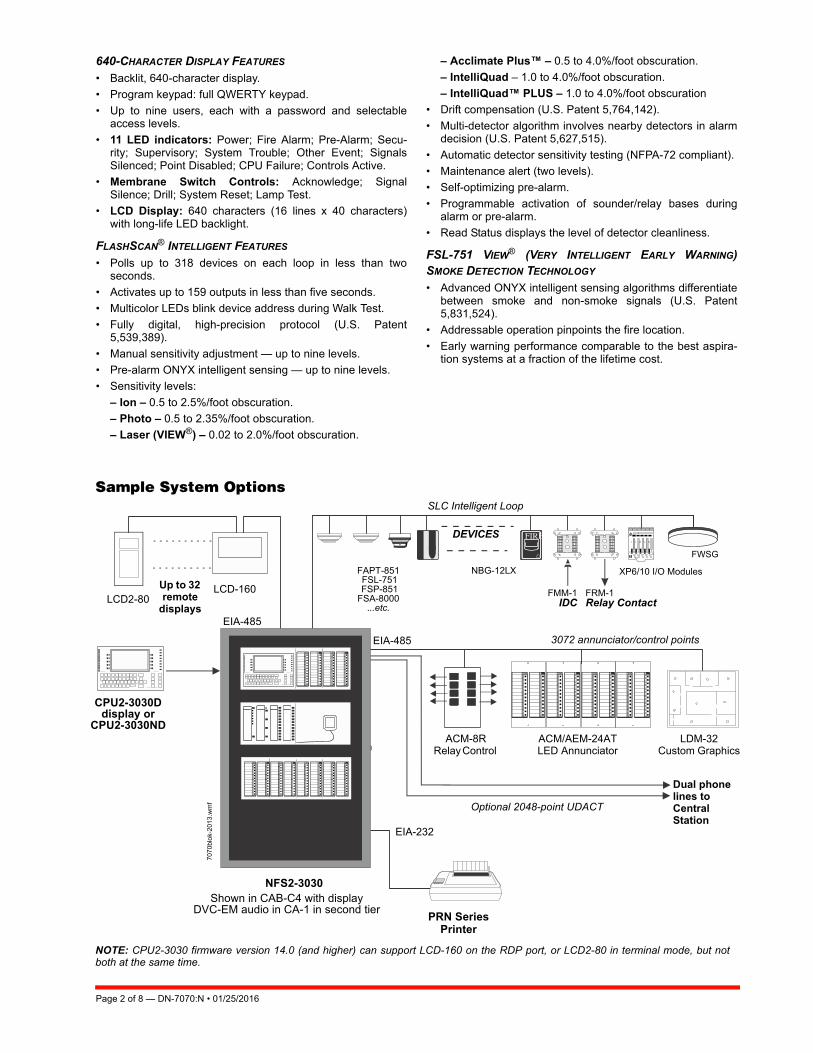
NOTE: CPU2-3030 firmware version 14.0 (and higher) can support LCD-160 on the RDP port, or LCD2-80 in terminal mode, but notboth at the same time.
CPU2-3030D display or
CPU2-3030ND
PRN Series Printer
NFS2-3030
Sample System Options
FAPT-851 FSL-751 FSP-851 FSA-8000
...etc.
Shown in CAB-C4 with displayDVC-EM audio in CA-1 in second tier
707
0blo
k-20
13.
wm
f
LCD-160LCD2-80
Up to 32 remote
displaysEIA-485
EIA-485
SLC Intelligent Loop
3072 annunciator/control points
Optional 2048-point UDACT
Dual phone lines to Central Station
EIA-232
DEVICES
ACM/AEM-24AT LED Annunciator
LDM-32 Custom Graphics
ACM-8R Relay Control
NBG-12LX XP6/10 I/O Modules
FMM-1IDC
FWSG
Page 2 of 8 — DN-7070:N • 01/25/2016
FAPT-851 ACCLIMATE PLUS™ LOW-PROFILE INTELLIGENT
MULTI-SENSOR
• Detector automatically adjusts sensitivity levels withoutoperator intervention or programming. Sensitivity increaseswith heat.
• Microprocessor-based technology; combination photo andthermal technology.
• Low-temperature signal at 40°F ± 5°F (4.44°C ± 2.77°C).
FSC-851 INTELLIQUAD ADVANCED MULTI-CRITERIA DETECTOR
• Detects all four major elements of a fire (smoke, heat, CO,and flame).
• Automatic drift compensation of smoke sensor and CO cell.
• High nuisance-alarm immunity.
INTELLIGENT FAAST® DETECTORS FSA-5000, FSA-8000,AND FSA-20000
• Connects directly to the SLC loop of compatible ONYXseries panels.
• Provides five event thresholds that can be individually pro-grammed with descriptive labels for control-by-event pro-gramming; uses five detector addresses.
• Uses patented particle separator and field-replaceable filterto remove contaminants.
• Advanced algorithms reject common nuisance conditions
• FSA-5000 covers 5,000 square feet through one pipe.• FSA-8000 covers 8,000 square feet through one pipe.
• FSA-20000 covers 28,800 square feet through one to fourpipes.
FCO-851 INTELLIQUAD™ PLUS
ADVANCED MULTI-CRITERIA FIRE/CO DETECTOR
• Detects all four major elements of a fire.• Separate signal for life-safety CO detection.• Optional addressable sounder base for Temp-3 (fire) or
Temp-4(CO) tone.• Automatic drift compensation of smoke sensor and CO cell.• High nuisance-alarm immunity.
FMM-4-20 GAS DETECTION MODULE
• Interface to industry-standard linear scale 4-20 mA sensors.
• Five programmable thresholds.
• FM Approved, Class 6320 (Stationary Gas Sensors/Detectors).
SWIFT WIRELESS
• Self-healing mesh wireless protocol.
• Each SWIFT Gateway supports up to 50 devices: 1 wire-less gateway and up to 49 SWIFT devices.
• Up to 4 wireless gateways can be installed with overlappingnetwork coverage.
RELEASING FEATURES
• Ten independent hazards.
• Sophisticated cross-zone (three options).
• Delay timer and Discharge timers (adjustable).
• Abort (four options).
VOICE AND TELEPHONE FEATURES
• Up to eight channels of digital audio.
• 35 watt, 50 watt, 75 watt, and 100/125 watt digital amplifiers(DAA2/DAX series and DS series).
• Solid state message generation.
• Hard-wired voice control module options.
• Firefighter telephone option.
• 30- to 120-watt analog amplifiers (AA Series).
• Backup tone generator and amplifier option.
FlashScan® Exclusive World-Leading Detector ProtocolAt the heart of the NFS2-3030 is a set of detection devices anddevice protocol — FlashScan (U.S. Patent 5,539,389). Flash-Scan is an all-digital protocol that gives superior precision andhigh noise immunity.
As well as giving quick identification of an active input device,this protocol can also activate many output devices in a frac-tion of the time required by competitive protocols. This highspeed also allows the NFS2-3030 to have the largest deviceper loop capacity in the industry — 318 points — yet everyinput and output device is sampled in less than two seconds.The microprocessor-based FlashScan® detectors have bicolorLEDs that can be coded to provide diagnostic information,such as device address during Walk Test.
ONYX Intelligent SensingONYX Intelligent Sensing is a set of software algorithms thatprovide the NFS2-3030 with industry-leading smoke detectioncapability. These complex algorithms require many calcula-tions on each reading of each detector, and are made possibleby the very high-speed microcomputer used by the NFS2-3030.
Drift Compensation and Smoothing. Drift compensationallows the detector to retain its original ability to detect actualsmoke, and resist false alarms, even as dirt accumulates. Itreduces maintenance requirements by allowing the system toautomatically perform the periodic sensitivity measurementsrequired by NFPA 72. Smoothing filters are also provided bysoftware to remove transient noise signals, usually caused byelectrical interference.
Maintenance Warnings. When the drift compensation per-formed for a detector reaches a certain level, the performanceof the detector may be compromised, and special warningsare given. There are three warning levels: (1) Low Chambervalue; (2) Maintenance Alert, indicative of dust accumulationthat is near but below the allowed limit; (3) MaintenanceUrgent, indicative of dust accumulation above the allowedlimit.
Sensitivity Adjust. Nine sensitivity levels are provided foralarm detection. These levels can be set manually, or canchange automatically between day and night. Nine levels ofpre-alarm sensitivity can also be selected, based on predeter-mined levels of alarm. Pre-alarm operation can be latching orself-restoring, and can be used to activate special control func-tions.
Self-Optimizing Pre-Alarm. Each detector may be set for“Self-Optimizing” pre-alarm. In this special mode, the detector“learns” its normal environment, measuring the peak analogreadings over a long period of time, and setting the pre-alarmlevel just above these normal peaks.
Cooperating Multi-Detector Sensing. A patented feature ofONYX Intelligent Sensing is the ability of a smoke sensor toconsider readings from nearby sensors in making alarm orpre-alarm decisions. Without statistical sacrifice in the ability toresist false alarms, it allows a sensor to increase its sensitivityto actual smoke by a factor of almost two to one.
DN-7070:N • 01/25/2016 — Page 3 of 8
Field Programming OptionsAutoprogram is a timesaving feature. The FACP “learns” whatdevices are physically connected and automatically loadsthem in the program with default values for all parameters.Requiring less than one minute to run, this routine allows theuser to have almost immediate fire protection in a new installa-tion, even if only a portion of the detectors are installed.
Keypad Program Edit. The NFS2-3030, like all NOTIFIERintelligent panels, has the exclusive feature of program cre-ation and editing capability from the front panel keypad, whilecontinuing to provide fire protection. The architecture of theNFS2-3030 software is such that each point entry carries itsown program, including control-by-event links to other points.This allows the program to be entered with independent per-point segments, while the NFS2-3030 simultaneously monitorsother (already installed) points for alarm conditions.
VERIFIRE® TOOLS
VeriFire® Tools is an offline programming and test utility thatcan greatly reduce installation programming time, andincrease confidence in the site-specific software. It is Win-dows® based and provides technologically advanced capabili-ties to aid the installer. The installer may create the entireprogram for the NFS2-3030 in the comfort of the office, test it,store a backup file, then bring it to the site and download froma laptop into the panel.
Product Line Information• “Configuration Guidelines” on page 4
• “Main System Components” on page 4
• “Networking Options” on page 4
• “Auxiliary Power Supplies and Batteries” on page 4
• “Audio Options” on page 5
• “Compatible Devices, EIA-232 Ports” on page 5
• “Compatible Devices, EIA-485 Ports” on page 5
• “Compatible Intelligent Devices” on page 5
• “Enclosures, Chassis, and Dress Plates” on page 6
• “Other Options” on page 7
CONFIGURATION GUIDELINES
Stand-alone and network systems require a main display. Onsingle-FACP systems (one NFS2-3030D), the display option isthe CPU2-3030D. On network systems (two or more net-worked fire panel nodes), at least one NCA-2, NCS, or ONYX-Works annunciation device is required. Options listed asfollows.
MAIN SYSTEM COMPONENTS
CPU2-3030D: NFS2-3030 Primary Display. CPU2-3030Dships with keypad/display installed; includes 640-characterbacklit LCD display, QWERTY programming and control key-pad. CPU2-3030 is a central processing unit and requires anAMPS-24(E) power supply. Non-English versions are avail-able: CPU2-3030D-FR, CPU2-3030D-HE, CPU2-3030D-KO,CPU2-3030D-PO, CPU2-3030D-SC, CPU2-3030D-SP, CPU2-3030D-TC, and CPU2-3030D-TH. For English Marine applica-tions order CPU2-3030D-M; for non-English Marine applica-tions order CPU2-3030D-M and the appropriate KP-KIT-XX.(See DN-60688.)
CPU2-3030ND: CPU2-3030 without display. Non-English ver-sions are available: CPU2-3030ND-FR, CPU2-3030ND-HE,CPU2-3030ND-KO, CPU2-3030ND-PO, CPU2-3030ND-SC,CPU2-3030ND-SP, CPU2-3030ND-TC.
LCM-320: Loop Control Module. Provides one SLC. NFS2-3030 supports up to five LCM-320s and five LEM-320 expand-ers for a total of ten SLCs. See DN-6881.
LEM-320: Loop Expander Module. Expands an LCM-320. SeeDN-6881.
SAMPLE SYSTEM: Four-loop NFS2-3030 with display:CPU2-3030D, DP-DISP, two BMP-1s, CHS-M3, two LCM-320s, two LEM-320s, AMPS-24, SBB-A4, DR-A4, BP2-4, BB-100, batteries.
NETWORKING OPTIONS
NCA-2: Network Control Annunciator, 640 characters. Analternate primary display for CPU2-3030 can be provided bythe NCA-2, NCS, or ONYXWorks. Using NCA-2 as primarydisplay enables non-English languages. On network systems(two or more networked fire panel nodes), one network display(either NCA-2, NCS, or ONYXWorks) is required for every sys-tem. On network systems, the NCA-2 connects (and requires)a standard Network Communication Module or High-SpeedNetwork Communication Module. Mounts in a row of FACPnode or in two annunciator positions. Mounting options includethe DP-DISP, ADP-4B, or in an annunciator box, such as theABS-2D. In CAB-4 top-row applications, a DP-DISP and twoBMP-1 blank modules are required for mounting. Non-Englishversions are available: NCA-2-FR, NCA-2-HE, NCA-2-KO,NCA-2-PO, NCA-2-SC, NCA-2-SP, NCA-2-TC, NCA-2-TH. Formarine applications, order NCA-2-M; for non-English marineapplications order NCA-2-M and appropriate KP-KIT-XX. SeeDN-7047.
NCM-W, NCM-F: Standard Network Communications Mod-ules. Wire and multi-mode fiber versions available. See DN-6861.
HS-NCM-W/MF/SF/WMF/WSF/MFSF: High-speed NetworkCommunications Modules that can connect to two nodes.Wire, single-mode fiber, multi-mode fiber, and media conver-sion models are available. See DN-60454.
RPT-W, RPT-F, RPT-WF: Standard-network repeater boardwith wire connection (RPT-W), multi-mode fiber connection(RPT-F), or allowing a change in media type between wire andfiber (RPT-WF). Not used with high-speed networks. See DN-6971.
ONYXWorks: UL-listed graphics PC workstation, ONYX-Works GUI software, and computer hardware. See DN-7048for specific part numbers.
NFN-GW-EM-3: NFN Gateway, embedded. (Replaces NFN-GW-EM.) See DN-60499.
NWS-3: NOTI•FIRE•NET™ Web Server. See DN-6928.
CAP-GW: Common Alerting Protocol Gateway. See DN-60756.
VESDA-HLI-GW: VESDAnet high-level interface gateway.See DN-60753.
LEDSIGN-GW: UL-listed sign gateway. Interfaces with classicand high-speed NOTI•FIRE•NET networks through the NFNGateway. See DN-60679.
OAX2-24V: UL-listed LED sign, used with LEDSIGN-GW. SeeDN-60679.
AUXILIARY POWER SUPPLIES AND BATTERIES
AMPS-24(E): One required for each NFS2-3030. Addressablepower supply and battery charger with two 24 VDC outputs.Addressable by any FlashScan® or CLIP mode FACP.Charges 7 to 200 AH batteries. Occupies up to five addresseson an SLC, depending on configuration. Primary input powerfor panel. See DN-6883.
APS2-6R: Auxiliary Power Supply. Provides up to 6.0amperes of power for peripheral devices. Includes batteryinput and transfer relay, and overcurrent protection. Mounts ontwo of four positions on a CHS-4L or CHS-4 chassis. See DN-5952.
Page 4 of 8 — DN-7070:N • 01/25/2016
ACPS-610: 6.0 A or 10.0 A addressable charging power sup-ply. See DN-60244.
FCPS-24S6/-24S8: Remote 6 A and 8 A power supplies withbattery charger. See DN-6927.
BAT Series: Batteries. AMPS-24 uses two 12 volt, 7 to 200 AHbatteries. See DN-6933.
AUDIO OPTIONS NOTE: See “Enclosures, Chassis, and Dress Plates” on page 6 formounting hardware.
DVC-EM: Digital Voice Command, digital audio processor withmessage storage for up to 32 minutes of standard quality (4minutes at high quality) digital audio. See DN-7045.
DVC-RPU: Digital Voice Command Remote Paging Unit foruse with DVC-EM. Includes the keypad/display. See DN-60726.
DS-DB: Digital Series Distribution Board, provides bulk ampli-fication capabilities to the DVC-EM while retaining digital audiodistribuition capabilities. Can be configured with up to four DS-AMPs, supplying high-level risers spread throughout an instal-lation. See DN-60565.
DVC-KD: DVC-EM keypad for local annunciation and controls;status LEDs and 24 user-programmable buttons. See DN-7045.
DS-AMP/E: 125W, 25 VRMS, or 100W, 70VRMS. 70VRMSrequires DS-XF70V step-up transformer. Digital Series Ampli-fier, part of the DS-DB system. See DN-60663.
DS-RFM, DS-FM, DS-SFM: Fiber conversion modules forDVC-EM, DS-DB distribution board, and DAA2/DAX Seriesamplifiers. See DN-60633.
DAA2-5025(E): 50W, 25 Vrms Digital Audio Amplifier assem-bly with power supply; includes chassis. See DN-60556.
DAA2-5070(E): 50W, 70.7 Vrms Digital Audio Amplifierassembly with power supply; includes chassis. See DN-60556.
DAA2-7525(E): 75W, 25 Vrms digital audio amplifier assemblywith power supply; includes chassis. See DN-60556.
DAX-3525(E): 35W, 25 Vrms Digital Audio Amplifier assemblywith power supply, includes chassis. See DN-60561.
DAX-3570(E): 35W, 70.7 Vrms Digital Audio Amplifier assem-bly with power supply, includes chassis. See DN-60561.
DAX-5025(E): 50W, 25 Vrms Digital Audio Amplifier assemblywith power supply, includes chassis. See DN-60561.
DAX-5070(E): 50W, 70.7 Vrms Digital Audio Amplifier assem-bly with power supply, includes chassis. See DN-60561.
TELH-1: Firefighter’s Telephone Handset for use with theDVC-EM when mounted in the CA-2 chassis. See DN-7045.
CMIC-1: Microphone used with DVC/DVC-EM. Included withCA-2 chassis assembly. See DN-7045.
RM-1/RM-1SA: Remote microphone assemblies, mount onADP-4 (RM-1) dress panel or CAB-RM/-RMR (RM-1SA)stand-alone cabinets. See DN-6728.
AA-30: Audio Amplifier, 30 watts, 25 Vrms. Includes amplifierand audio input supervision, backup input, and automatic swi-tchover, power supply, cables. See DN-3224.
AA-120/AA-100: Audio Amplifier. AA-120 is 120 watts, 25Vrms. AA-100 is 100 watts, 70.7 Vrms. The amplifier containsan integral chassis for mounting to a CAB-B4, -C4, or -D4backbox (consumes one row). Includes audio input and ampli-fied output supervision, backup input, and automatic switcho-ver to backup tone. See DN-3224.
DAA Series Digital Audio Amplifiers: Legacy DAA Seriesamplifiers are compatible with DVC systems running SR4.0.For specific information on DAA-50 series amplifiers, refer toDN-7046. For information on DAA-7525 Series, refer to DN-60257.
COMPATIBLE DEVICES, EIA-232 PORTS
PRN-6: 80-column printer. See DN-6956.
PRN-7: 80-column printer. See DN-60897
VS4095/5: Printer, 40-column, 24 V. Order from Keltron, Inc.See DN-3260.
DPI-232: Direct Panel Interface, specialized modem forextending serial data links to remotely located FACPs and/orperipherals. See DN-6870.
COMPATIBLE DEVICES, EIA-485 PORTS
ACM-24AT: ONYX® Series ACS annunciator – up to 96 pointsof annunciation with Alarm or Active LED, Trouble LED, andswitch per circuit. Active/Alarm LEDs can be programmed (bypowered-up switch selection) by point to be red, green, or yel-low; the Trouble LED is always yellow. See DN-6862.
AEM-24AT: Same LED and switch capabilities as ACM-24AT;expands the ACM-24AT to 48, 72, or 96 points. See DN-6862.
ACM-48A: ONYX® Series ACS annunciator – up to 96 pointsof annunciation with Alarm or Active LED per circuit. Active/Alarm LEDs can be programmed (by powered-up switchselection) in groups of 24 to be red, green, or yellow. Expand-able to 96 points with one AEM-48A. See DN-6862.
AEM-48A: Same LED capabilities as ACM-48A; expands theACM-48A to 96 points. See DN-6862.
ACM-8R: Remote Relay Module with eight Form-C contacts.Can be located up to 6,000 ft. (1828.8 m) from panel on fourwires. See DN-3558.
LCD-160: Liquid Crystal Display annunciator, 160-characterbacklit. Can store character sets for multiple languages. Sup-ports Canadian requirements. See DN-6940.
LCD2-80: Terminal and ACS mode. 80-character, backlit LCDdisplay. Mounts up to 6,000 ft. (1828.8 m) from panel. Up to 32per FACP. See LCD2-80 (DN-60548).
SCS Series: Smoke control station; eight (expandable to 16)circuits. See DN-4818.
TM-4: Transmitter Module. Includes three reverse-polarity cir-cuits and one municipal box circuit. Mounts in panel moduleposition (as in single-address mode applications) or in CHS-M3 position. See DN-6860.
UDACT-2: Universal Digital Alarm Communicator Transmitter,636 channel. See DN-60686.
UZC-256: Programmable Universal Zone Coder provides pos-itive non-interfering successive zone coding. Microprocessor-controlled, field-programmable from IBM®-compatible PCs(requires optional programming kit). Mounts on a CHS-4series chassis within NFS2-3030.
COMPATIBLE INTELLIGENT DEVICES
FWSG Wireless SWIFT Gateway: Addressable gateway sup-ports wireless SLC devices. Not appropriate for ULC applica-tions. See DN-60820.
FSA-5000: Intelligent FAAST® XS Fire Alarm Aspiration Sens-ing Technology. Intelligent aspirating smoke detector for appli-cations up to 5,000 sq.ft. For Canadian applications, orderFSA-5000A.
FSA-8000: Intelligent FAAST® XM Fire Alarm AspirationSensing Technology. Intelligent aspirating smoke detector forapplications up to 8,000 sq.ft. For Canadian applications,order FSA-8000A. See DN-60792.
DN-7070:N • 01/25/2016 — Page 5 of 8
FSA-20000: Intelligent FAAST® XT Fire Alarm AspirationSensing Technology. Intelligent aspirating smoke detector forapplications up to 28,800 sq.ft. For Canadian applications,order FSA-20000A. See DN-60849.
FSB-200: Intelligent beam smoke detector. See DN-6985.
FSB-200S: Intelligent beam smoke detector with integral sen-sitivity test. See DN-6985.
FSC-851: FlashScan IntelliQuad Advanced Multi-CriteriaDetector. See DN-60412.
FCO-851: FlashScan IntelliQuad PLUS Advanced Multi-Crite-ria Fire/CO Detector. See DN-60689.
FSI-851: Low-profile FlashScan ionization detector. See DN-6985.
FSP-851: Low-profile FlashScan photoelectric detector. SeeDN-6935.
FSP-851R: Low-profile intelligent photoelectric sensor, remotetest capable. For use with DNR(W). See DN-6935.
FSP-851T: Low-profile FlashScan photoelectric detector with135°F (57°C) thermal. See DN-6935.
FST-851: FlashScan thermal detector 135°F (57°C). See DN-6936.
FST-851R: FlashScan thermal detector 135°F (57°C) withrate-of-rise. See DN-6936.
FST-851H: FlashScan 190°F (88°C) high-temperature thermaldetector. See DN-6936.
FAPT-851: FlashScan Acclimate Plus™ low-profile multi-sen-sor detector. See DN-6937.
FSL-751: FlashScan VIEW® laser photo detector. See DN-6886.
DNR: InnovairFlex low-flow non-relay duct-detector housing(order FSP-851 separately). Replaces FSD-751PL/FSD-751RPL. See DN-60429.
DNRW: Same as above with NEMA-4 rating, watertight. SeeDN-60429.
B224RB: Low-profile relay base. See DN-60054.
B224BI: Isolator base for low-profile detectors. See DN-60054.
B210LP: Low-profile base. Standard U.S. style. ReplacesB710LP. See DN-60054.
B501: European-style, 4" (10.16 cm) base. See DN-60054.
B200S: Intelligent programmable sounder base, capable ofproducing a variety of tone patterns including ANSI Temporal3. Compatible with sychronization protocol. See DN-60054.
B200S-LF: Low-frequency version of B200S. See DN-60054.
B200SCOA: Based on B200SA, with added CO detectormarkings in English/French. For Canadian applications only.
B200SR: Sounder base, Temporal 3 or Continuous tone. SeeDN-60054.
B200SR-LF: Low-frequency version of B200SR. See DN-60054.
FMM-1: FlashScan monitor module. See DN-6720.
FDM-1: FlashScan dual monitor module. See DN-6720.
FZM-1: FlashScan two-wire detector monitor module. SeeDN-6720.
FMM-101: FlashScan miniature monitor module. See DN-6720.
FMM-4-20: FlashScan 4-20 mA protocol monitor module. SeeDN-60411.
FCM-1: FlashScan control module. See DN-6724.
FCM-1-REL: FlashScan releasing control module. See DN-60390.
FTM-1: Firephone Telephone Module connects a remote fire-fighter telephone to a centralized telephone console. Reportsstatus to panel. Wiring to jacks and handsets is supervised.See DN-6989.
FRM-1: FlashScan relay module. See DN-6724.
FDRM-1: FlashScan dual monitor/dual relay module. See DN-60709.
NBG-12LX: Manual pull station, addressable. See DN-6726.
ISO-X: Isolator module. See DN-2243.
ISO-6: Six Fault isolator module. For Canadian applicationsorder ISO-6A. See DN-60844.
XP6-C: FlashScan six-circuit supervised control module. SeeDN-6924.
XP6-MA: FlashScan six-zone interface module; connectsintelligent alarm system to two-wire conventional detectionzone. See DN-6925.
XP6-R: FlashScan six-relay (Form-C) control module. SeeDN-6926.
XP10-M: FlashScan ten-input monitor module. See DN-6923.
SLC-IM: SLC integration module, for VESDAnet detectors.See DN-60755.
ENCLOSURES, CHASSIS, AND DRESS PLATES
CAB-4 Series Enclosure: NFS2-3030 mounts in a standardCAB-4 Series enclosure (available in four sizes, “A” through“D”). Backbox and door ordered separately; requires BP2-4battery plate. A trim ring option is available for semi-flushmounting. See DN-6857.
EQ Series Cabinets: EQ series cabinets will house amplifiers,power supplies, battery chargers and control modules. EQcabinets are available in three sizes, “B” through “D”. See DN-60229.
CAB-BM Marine System: Protects equipment in shipboardand waterfront applications. Order CPU2-3030D-M; for non-English marine applications order CPU2-3030D and appropri-ate KP-KIT-XX. Also order BB-MB for systems using 100 AHbatteries. For a full list of required and optional equipment, seeDN-60688.
CHS-M3: Mounting chassis for CPU2-3030. One required foreach CPU2-3030D/3030ND.
CA-2: Chassis for FACP control panel when DVC-EM is usedwith firefighter's telephone. Mounts in the top two rows of aCAB-4 series enclosure.
DP-DISP: Dress panel for top row in cabinet with CPU2-3030D installed.
DP-1B: Blank dress panel. Provides dead-front panel forunused tiers; covers DAA2/DAX series or AA-series amplifier.See DN-7046.
CHS-BH1: Battery chassis; holds two 12.0 AH batteries.Mounts on the left side of DAA2 chassis. See DN-7046.
CA-1: Chassis, occupies one tier of a CAB-4 Series enclo-sure. The left side accommodates one DVC-EM and a DVC-KD (optional); and the right side houses a CMIC-1 microphoneand its well (optional). See DN-7045.
CA-2: Chassis assembly, occupies two tiers of a CAB-4 Seriesenclosure. The left side accommodates one DVC-EM mountedon a half-chassis and one NFS2-3030 or NCA-2 mounted on ahalf-chassis. The right side houses a microphone/handsetwell. The CA-2 assembly includes CMIC-1 microphone. ADDRSeries doors with two-tier visibility are available for use with
Page 6 of 8 — DN-7070:N • 01/25/2016
the CA-2 configuration: ADDR-B4, ADDR-C4, ADDR-D4(below).
ADDR-B4: Two-tier-sized door designed for use with the CA-2chassis configuration. ADDR Series doors are similar to CAB-4 Series “DR” doors, but a clear window space exposes thetop two tiers of the CAB-4 enclosure. Use an SBB-B4 backboxwith the ADDR-B4. See DN-7045, DN-6857.
ADDR-C4: Three-tier-sized door designed for use with theCA-2 chassis configuration. ADDR Series doors are similar toCAB-4 Series “DR” doors, but a clear window space exposesthe top two tiers of the CAB-4 enclosure. Use an SBB-C4backbox with the ADDR-C4. See DN-7045, DN-6857.
ADDR-D4: Four-tier-sized door designed for use with the CA-2 chassis configuration. ADDR Series doors are similar toCAB-4 Series “DR” doors, but a clear window space exposesthe top two tiers of the CAB-4 enclosure. Use an SBB-D4backbox with the ADDR-D4. See DN-7045, DN-6857.
DPA-1: Dress panel, used with the CA-1 chassis when config-ured with a DVC-EM, DVC-KD, and CMIC-1. See DN-7045.
DPA-2: Dress Panel used with the CA-2 chassis assembly.
DPA-1A4: Dress panel, used with the CA-1 chassis when theCMIC-1 is not used. Provides mounting options on right twobays for two ACS annunciators, or for blank plates. See DN-7045.
ADP-4B: Annunciator dress plate. Mounts in rows 2, 3 or 4 ofa CAB-4 series enclosure. Used with ACS series annuncia-tors.
BMP-1: Blank module for unused module positions.
DP-1B: Blank dress panel. Provides dead-front panel forunused tiers; covers DAA2/DAX series or AA-series amplifier.
BP2-4: Battery plate, required.
CHS-4L: Low-profile four-position Chassis. Mounts two AA-30amplifiers.
CHS-4N: Chassis for mounting up to four APS-6Rs.
CHS-6: Chassis used with the XP6 and XP10 Multi-Modules.Mounts up to six modules in any CAB-4 series row.
BB-100: Backbox for batteries and power supplies. The BB-100 is used to mount up to two 100 AH batteries and powersupply, if needed. 30" (76.20 cm) wide x 25" (63.50 cm) high x7.5" (19.05 cm) deep; depth includes door.
BB-200: Backbox for batteries and power supplies. Holds upto four 100 AH batteries (200 AH capacity) and power supply.30" (76.20 cm) wide x 36" (91.44 cm) high x 7.5" (19.05 cm)deep; depth includes door.
NFS-LBB: Battery Box. The NFS-LBB is used to mount up totwo 55 AH batteries. Dimensions: Box: 24" (610 mm) wide x14" (356 mm) high x 7.75" (197 mm) deep. Door: 24.125" (613mm) wide x 14.25" (362 mm) high; door adds 0.0625" (approx.1.6 mm) to depth.
BB-UZC: Backbox for housing the UZC-256 for applicationswhere the UZC will not fit in panel enclosure. Black; for red,order BB-UZC-R. See DN-3404.
SEISKIT-CAB: Seismic mounting kit. Required for seismic-certified applications with NFS2-3030 and other equipmentmounted in CAB-4 Series Enclosures. Includes battery bracketfor two 26 AH batteries.
SEISKIT-LBB: Seismic kit for the NFS-LBB. Includes batterybracket for two 55 AH batteries.
OTHER OPTIONS
411: Slave digital alarm communicator. See DN-6619.
411UDAC: Digital alarm communicator. See DN-6746.
IPDACT-2, IPDACT Internet Monitoring Module: Connectsto primary and secondary DACT telephone output ports forinternet communications over customer-provided Ethernetconnection. Requires compatible Teldat VisorALARM CentralStation Receiver. Can use DHCP or static IP. See DN-60408.
IPCHSKIT: IP Communicator Chassis Mounting Kit. Formounting an IPDACT-2/2UD onto the panel chassis or CHS-4series chassis. Use IPENC for external mounting applications.
IPSPLT: Y-adapter option allow connection of both panel dialeroutputs to one IPDACT-2/2UD cable input.
IPENC: External enclosure for IPDACT, includes IPBRKTmounting bracket; Red; for black, order IPENC-B.
IPGSM-4G: Internet and Digital Cellular Fire Alarm Communica-tor. Provides selectable configurable paths: cellular only, IP only,or IP primary with cellular backup. Connects to the primary andsecondary ports of a DACT. For Canadian applications orderIPGSM-4GC. See DH-60769.
NOTE: For other options including compatibility with retrofit equip-ment, refer to the panel's installation manual, the SLC manual, andthe Device Compatibility Document.
System Specifications
SYSTEM CAPACITY
• Intelligent Signaling Line Circuits ...........1 expandable to 10
• Intelligent detectors .......................................... 159 per loop
• Addressable monitor/control modules .............. 159 per loop
• Programmable software zones............................. over 2000
• ACS annunciators per CPU2-3030 .......................32 address x 64 or 96 points
NOTE: The CPU2-3030 can support up to 96 annunciatoraddress points per ACM-24AT/-48A.
SPECIFICATIONS
Primary Input Power:
– AMPS-24: 110-120 VAC, 50/60 Hz, 4.5 A maximum.
– AMPS-24E: 240 VAC, 50/60 Hz, 2.25 A maximum.
DC Output:
– Main 24 VDC: Up to 5.0 A
– Aux 24 VDC: Up to 5.0 A
– 5 VDC: Up to 0.15 A.
Current draw (Standby/Alarm):
– CPU2-3030D board: 0.340 A.
– CPU2-3030ND board: 0.120 A.
– LCM-320: 0.130 A.
– LEM-320: 0.100 A.
– AMPS-24(E)*: 0.13 A. (Draws power from secondary power source only.)
NOTE: See AMPS-24(E) Manual 51907 for a complete currentdraw calculation sheet and details of input and output values.
Battery charger range: 7 AH – 200 AH. Use separate cabinetfor batteries over 26 AH.
Float Rate: 27.6 V.
SHIPPING WEIGHT
• CPU2-3030D: 5.95 lb (2.70 kg).
• CPU2-3030ND: 2.90 lb (1.32 kg).
TEMPERATURE AND HUMIDITY RANGES
This system meets NFPA requirements for operation at 0 –49°C/32 – 120°F and at a relative humidity 93% ± 2% RH(noncondensing) at 32°C ± 2°C (90°F ± 3°F). However, theuseful life of the system's standby batteries and the electronic
DN-7070:N • 01/25/2016 — Page 7 of 8
IntelliQuad™, NOTI•FIRE•NET™, ONYXWorks™, and SWIFT™ are alltrademarks; and Acclimate® Plus™, FlashScan®, Intelligent FAAST®,NOTIFIER®, ONYX®, VeriFire® Tools, and VIEW® are all registeredtrademarks of Honeywell International Inc. ©2016 by Honeywell International Inc. All rights reserved. Unauthorized useof this document is strictly prohibited.
components may be adversely affected by extreme tempera-ture ranges and humidity. Therefore, it is recommended thatthis system and its peripherals be installed in an environmentwith a normal room temperature of 15 – 27°C/60 – 80°F.
AGENCY LISTINGS AND APPROVALS
These listings and approvals apply to the modules specified inthis document. In some cases, certain modules or applicationsmay not be listed by certain approval agencies, or listing maybe in process. Consult factory for latest listing status.
• UL Listed: S635.
• ULC Listed: S635.
• MEA: 232-06-E.
• Fire Dept. of New York: COA#6114.
• CSFM: 7165-0028:0224 (Commercial).
• FM Approved.
• FM6320 Approved. Class 6320 for Gas Detection.
• City of Chicago.
• City of Denver.
• Singapore Productivity and Standards Board (PSB).
• CCCF listed.
• Fire Services Department (Hong Kong).
Marine Applications: Marine approved systems must be con-figured using components itemized in this document. (SeeMain System Components, in “Product Line Information.) Spe-cific connections and requirements for those components aredescribed in the installation document, PN 54756. When theserequirements are followed, systems are approved by the fol-lowing agencies:
• US Coast Guard 161.002/55/0 (Standard 46 CFR and161.002).
• Lloyd's Register 11/600013 (ENV 3 category).• American Bureau of Shipping (ABS) Type Approval. NOTE: For information on marine applications, see DN-60688.
STANDARDS
The NFS2-3030 complies with the following UL Standards andNFPA 72, International Building Code (IBC), and CaliforniaBuilding Code (CBC) Fire Alarm Systems requirements:
• UL 864 (Fire).
• UL 1076 (Burglary).
• UL 2572 (Mass Notification Systems). (NFS2-3030 version20 or higher)
• LOCAL (Automatic, Manual, Waterflow and SprinklerSupervisory).
• AUXILIARY (Automatic, Manual and Waterflow) (requiresTM-4).
• REMOTE STATION (Automatic, Manual, Waterflow andSprinkler Supervisory) (requires TM-4).
• PROPRIETARY (Automatic, Manual, Waterflow and Sprin-kler Supervisory). Not applicable for FM.
• EMERGENCY VOICE/ALARM.
• OT, PSDN (Other Technologies, Packet-switched Data Net-work).
• IBC 2012, IBC 2009, IBC 2006, IBC 2003, IBC 2000 (Seis-mic).
• CBC 2007 (Seismic).
Page 8 of 8 — DN-7070:N • 01/25/2016
This document is not intended to be used for installation purposes. We try to keep our product information up-to-date and accurate.
We cannot cover all specific applications or anticipate all requirements. All specifications are subject to change without notice.
For more information, contact Notifier. Phone: (203) 484-7161, FAX: (203) 484-7118.www.notifier.com
Made in the U.S. A.
N500-46-00 4 I56-1169-07 © 2001 Notifier
WARNING
All relay switch contacts are shipped in the standby state (open) state, but may have transferred to the activated (closed) state during shipping. To ensure that the switch contacts are in their correct state, modules must be made to communicate with the panel before connecting circuits controlled by the module.
Relay Contact Ratings:
CURRENT RATING MAXIMUM VOLTAGE LOAD DESCRIPTION APPLICATION3 A
2 A
.9 A
.9 A
.5 A
1 A
.5 A
.7 A
30 VDC
30 VDC
110 VDC
125 VAC
30 VDC
30 VDC
125 VAC
75 VAC
Resistive
Resistive
Resistive
Resistive
Inductive (L/R=5ms)
Inductive (L/R=2ms)
Inductive (PF=.35)
Inductive (PF=.35)
Non Coded
Coded
Non Coded
Non Coded
Coded
Coded
Non Coded
Non Coded
LABEL
J1 UNDER LABEL
BACK OFMODULE
N500-46-00 1 I56-1169-07
FCM-1 Supervised Control Module
INSTALLATION AND MAINTENANCE INSTRUCTIONS
12 Clintonville Rd Northford, CT 06472-1653
(203) 484-7161
Before InstallingThis information is included as a quick reference installation guide. Refer to the control panel installation manual for detailed system information. If the modules will be installed in an existing operational system, inform the operator and local authority that the system will be temporarily out of service. Disconnect power to the control panel before installing the modules.
NOTICE: This manual should be left with the owner/user of this equipment.
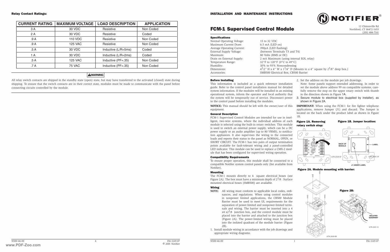
General DescriptionFCM-1 Supervised Control Modules are intended for use in intel-ligent, two-wire systems, where the individual address of each module is selected using the built-in rotary switches. This module is used to switch an external power supply, which can be a DC power supply or an audio amplifier (up to 80 VRMS), to notifica-tion appliances. It also supervises the wiring to the connected loads and reports their status to the panel as NORMAL, OPEN, or SHORT CIRCUIT. The FCM-1 has two pairs of output termination points available for fault-tolerant wiring and a panel-controlled LED indicator. This module can be used to replace a CMX-2 mod-ule that has been configured for supervised wiring operation.
Compatibility RequirementsTo ensure proper operation, this module shall be connected to a compatible Notifier system control panels only (list available from Notifier).
MountingThe FCM-1 mounts directly to 4 square electrical boxes (see Figure 2A). The box must have a minimum depth of 21/8 . Surface mounted electrical boxes (SMB500) are available.
WiringNOTE: All wiring must conform to applicable local codes, ordi-
nances, and regulations. When using control modules in nonpower limited applications, the CB500 Module Barrier must be used to meet UL requirements for the separation of power-limited and nonpower-limited termi-nals and wiring. The barrier must be inserted into a 4 x4 x21/8 junction box, and the control module must be placed into the barrier and attached to the junction box (Figure 2A). The power-limited wiring must be placed into the isolated quadrant of the module barrier (Figure 2B).
1. Install module wiring in accordance with the job drawings and appropriate wiring diagrams.
Figure 1A. Removingrotary switch stop:
Figure 2A. Module mounting with barrier:
A78-2611-11
A78-2610-08
SpecificationsNormal Operating Voltage: 15 to 32 VDCMaximum Current Draw: 6.5 mA (LED on)Average Operating Current: 390µA (LED flashing)External Supply Voltage: (between Terminals T3 and T4)Maximum: 80 Volts (RMS or DC)Drain on External Supply: 2 mA Maximum (using internal EOL relay)Temperature Range: 32°F to 120°F (0°C to 49°C)Humidity: 10% to 93% NoncondensingDimensions: 41/2” H x 4” W x 11/4” D (Mounts to a 4” square by 21/8” deep box.)Accessories: SMB500 Electrical Box; CB500 Barrier
2. Set the address on the module per job drawings. Note: Some panels support extended addressing. In order to
set the module above address 99 on compatible systems, care-fully remove the stop on the upper rotary switch with thumb in the direction shown in Figure 1A.
3. Secure module to electrical box (supplied by installer), as shown in Figure 2A.
IMPORTANT: When using the FCM-1 for fire fighter telephone applications, remove Jumper (J1) and discard. The Jumper is located on the back under the product label as shown in Figure 1B.
9
8
7
6
5 4
3
2
1
0
012345 6 7 8 9
TENS
ONESADDRESSLOOP
0
7 865432
1
910111213
1415
ISOLATEDQUADRANT
01
23
4
98
76
5
0
TENS
ONES
ADDRESS
LOOP9
87654321
09
87654321 101112131415
01
23
4
98
76
5
0
TENS
ONES
ADDRESS
LOOP9
87654321
09
87654321 101112131415
Figure 1B. Jumper location:
A78-2318-18
Figure 2B:
A78-2318-07
www.PDF-Zoo.com

MODULE
FROM PANEL OR(+)(—)TO NEXT
(+)(—)
DEVICE
(+)(—)
CONTROL
(—)
(+)
(—)
(+)
TO NEXT CONTROL MODULE LAST MODULE MUST RETURNWIRES FOR SUPERVISION
MODULE POLARITIES ARESHOWN IN ALARM
CONNECT MODULES TO LISTED COMPATIBLE
AUDIO CIRCUIT
3 & 4. BREAK WIRE TO ENSURESUPERVISION OF CONNECTIONS.
DO NOT LOOP WIRE AROUND TERMINALS
ALL WIRING SHOWN IS SUPERVISED.
(+)
NOTIFIER CONTROL PANELS ONLY
PREVIOUS DEVICE
47 K EOLRESISTORELR-47K
32 VDC MAX.TWISTED PAIR
IS RECOMMENDED
COMMUNICATION LINE
(—)AUDIO AMPLIFIER, 70.7 Vrms MAX.
USE ONLY MODELS AA-30, AA100 OR AA-120. AMPLIFIERMUST PROVIDE WIRING SUPERVISION PER NFPA.
SPEAKER SWITCHING CIRCUIT - NFPA STYLE WSPEAKERS MUST BE LISTED FOR FIRE PROTECTION. REFER
TO THE RELAY CONTACT RATING TABLE FOR MAXIMUM LOAD.
WIRES MUST BE SUPERVISED PER NFPA
WHEN A 70.7V AUDIO AMPLIFIER IS USED, TERMINALS 1 AND 2 ARE POWER LIMITED,WHILE TERMINALS 3-9 ARE NONPOWER LIMITED. IN THIS CASE THE CB500 BARRIER IS REQUIRED. OTHERWISE, ALL TERMINAL WIRING IS POWER LIMITED.¹ THE CB500 INCLUDES A LABEL INDICATING WHICH TERMINALS ARE NONPOWER LIMITED. THISLABEL MUST BE PLACED OVER THE POWER-LIMITED TERMINAL INFORMATION ON THE NAMEPLATE LABEL, PRESENT ON THE MODULE HOUSING.
AUDIO CIRCUIT WIRING MUST BE TWISTED PAIR AS A MINIMUM.SEE NOTIFIER INSTALLATION MANUAL FOR DETAILED INFORMATION.
SUPERVISION
9
8
7
6
5 4
3
2
1
0
012345 6 7 8 9
TENS
ONESADDRESSLOOP
0
7 865432
1
910111213
1415
MODULE
FROM PANEL OR(+)(—)TO NEXT
(+)(—)
DEVICE
(+)(—)
CONTROL
TO NEXT CONTROL MODULE LAST MODULE MUST RETURNWIRES FOR SUPERVISION
MODULE POLARITIES ARESHOWN IN ALARM
CONNECT MODULES TO LISTED COMPATIBLE
AUDIO CIRCUIT
3 & 4. BREAK WIRE TO ENSURESUPERVISION OF CONNECTIONS.
DO NOT LOOP WIRE AROUND TERMINALS
ALL WIRING SHOWN IS SUPERVISED.
(+)
NOTIFIER CONTROL PANELS ONLY
PREVIOUS DEVICE
47 K EOLRESISTORIS INTERNALAT TERMINALS8 AND 9
32 VDC MAX.TWISTED PAIR
IS RECOMMENDED
COMMUNICATION LINE
(—) AUDIO AMPLIFIER, 70.7 Vrms MAX.USE ONLY MODELS AA-30, AA100 OR AA-120. AMPLIFIER
MUST PROVIDE WIRING SUPERVISION PER NFPA.
SPEAKER SWITCHING CIRCUIT - NFPA STYLE XSPEAKERS MUST BE LISTED FOR FIRE PROTECTION. REFER
TO THE RELAY CONTACT RATING TABLE FOR MAXIMUM LOAD.
WIRES MUST BE SUPERVISED PER NFPA
WHEN A 70.7V AUDIO AMPLIFIER IS USED, TERMINALS 1 AND 2 ARE POWER LIMITED,WHILE TERMINALS 3-9 ARE NONPOWER LIMITED. IN THIS CASE THE CB500 BARRIER IS REQUIRED. OTHERWISE, ALL TERMINAL WIRING IS POWER LIMITED.¹ THE CB500 INCLUDES A LABEL INDICATING WHICH TERMINALS ARE NONPOWER LIMITED. THISLABEL MUST BE PLACED OVER THE POWER-LIMITED TERMINAL INFORMATION ON THE NAMEPLATE LABEL, PRESENT ON THE MODULE HOUSING.
AUDIO CIRCUIT WIRING MUST BE TWISTED PAIR AS A MINIMUM.SEE NOTIFIER INSTALLATION MANUAL FOR DETAILED INFORMATION.
SUPERVISION
(—)
(+)
(—)
(+)BYPASS CAPACITORS : 100 ¹ f, 16V
A2143-20 NONPOLARIZED <10 A LEAKAGE
9
8
7
6
5 4
3
2
1
0
012345 6 7 8 9
TENS
ONESADDRESSLOOP
0
7 865432
1
910111213
1415
MODULE
FROM PANEL OR(+)(-)
TO NEXT (+)(-)
DEVICE
(+)(-)
CONTROL
(-)
(+)
47K EOLRESISTORELR-47K
UL LISTED EOL RELAYSHOWN ENERGIZED24 VDC COILA77-716-02
TO NEXT CONTROL MODULE OR END-OF-LINE-RELAY.ONE RELAY REQUIRED FOR EACH CIRCUIT.SOME CONTROL PANELS HAVE RELAY BUILT IN ANDDO NOT REQUIRE EXTERNAL WIRING. REFER TO NOTIFIER MANUAL.
MODULE POLARITIES ARESHOWN IN ALARM
CONNECT MODULES TO LISTED COMPATIBLE32 VDC MAX.
IS RECOMMENDED
24 VDC CIRCUIT
3 & 4. BREAK WIRE RUN TO PROVIDESUPERVISION OF CONNECTIONS.
DO NOT LOOP WIRE ON TERMINALS
ALL WIRING SHOWN IS SUPERVISED AND POWER LIMITED
(-)(+)
TWISTED PAIRNOTIFIER CONTROL PANELS ONLY
COMMUNICATION LINE
PREVIOUS DEVICE
(-)
(+)
24 VDC POWER SUPPLYISOLATED, REGULATED, POWER LIMITED PER NFPA 70.LISTED FOR FIRE PROTECTION WITH BATTERY BACKUP.
9
8
7
6
5 4
3
2
1
0
012345 6 7 8 9
TENS
ONESADDRESSLOOP
0
7 865432
1
910111213
1415
MODULE
FROM PANEL OR(+)
(—)TO NEXT
(+)
(—)
DEVICE
(+)(—)
CONTROL
(—)
(+)
(—)
(+)
UL LISTED EOL RELAYSHOWN ENERGIZED
24VDC COILA77-716B
MODULE POLARITIES ARESHOWN IN ALARM
CONNECT MODULES TO LISTED COMPATIBLE
24 VDC CIRCUIT
3 & 4. BREAK WIRE RUN TO PROVIDESUPERVISION OF CONNECTIONS.
DO NOT LOOP WIRE ON TERMINALS
ALL WIRING SHOWN IS SUPERVISEDAND POWER LIMITED
(+)
NOTIFIER CONTROL PANELS ONLY
PREVIOUS DEVICE
EOL RESISTOR ISINTERNAL AT
TERMINALS 8 & 9
32 VDC MAX.TWISTED PAIR
IS RECOMMENDED
COMMUNICATION LINE
(—) 24 VDC POWER SUPPLYISOLATED, REGULATED, POWER LIMITED PER NFPA 70.LISTED FOR FIRE PROTECTION WITH BATTERY BACKUP.
TO NEXT CONTROL MODULE OR END-OF-LINE-RELAY.ONE RELAY REQUIRED FOR EACH CIRCUIT.SOME CONTROL PANELS HAVE RELAY BUILT IN ANDDO NOT REQUIRE EXTERNAL WIRING. REFER TO NOTIFIER MANUAL.
9
8
7
6
5 4
3
2
1
0
012345 6 7 8 9
TENS
ONESADDRESSLOOP
0
7 865432
1
910111213
1415
N500-46-00 3 I56-1169-07
Figure 5. Typical wiring for speaker supervision and switching, NFPA Style Y:
Figure 6. Typical fault tolerant wiring for speaker supervision and switching, NFPA Style Z:
A78-2284-11
A78-2285-10
CONNECT MODULES TO LISTED COMPATIBLENOTIFIER CONTROL PANELS ONLY
N500-46-00 2 I56-1169-07
Figure 3. Typical notification appliance circuit configuration, NFPA Style Y:
Figure 4. Typical fault tolerant notification appliance circuit configuration, NFPA Style Z:
A78-2283-12
A78-2282-12
A77-716B
www.PDF-Zoo.com
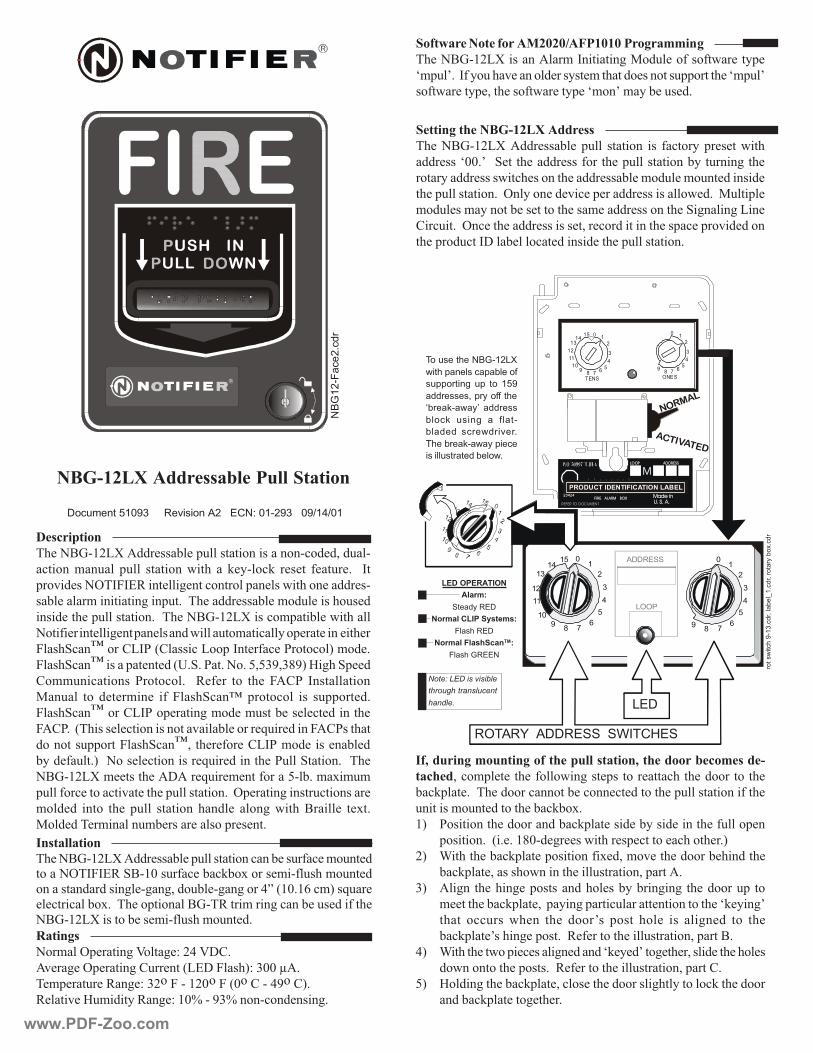
����
��
�������
4 3 2 1
� �
��
��
��
����
��� �
� �
� �
� �
�� ��
� � � �� �� �
������������� ���12345678901231234567890123123456789012312345678901231234567890123
�������
����
�
�
�
���
�
�
�
�
���
�
�
�
�
�����������
�� ���
��������
���� ��������������
��� ���
���� ���� ���� ���
��� �����
������������� ��
�������������������
�������
�������������� �����������
����������� ���������������� �������� ��� �������������������
����������� !� �"���������������������������������������������#����
�������������������������������������������$������$�������������
���������������� ��%����������&�������������������������� ��'�������
$�������$�����������������������$�����������������"�#�����#�����
(������ ��%����������������������)���������������������������&�������
������������*+��������������������������������������
�� ����������������������������
�����������
����������� ��������������������������������������)������
������� $������ ����� �������� ����� �� ,������,� ������ ������� � � *�
���&������%�*-*./��������#�����������������������������������
����������$����������#������ ������������������$���������������
����������������������� ������������������$����������������
����������������#������������������������$��������������������������
-����"���0����(�*1�2(������������*���������1�������3�$���
-����"���0���������������24 " �1�� ��� �5)567)6873�9�#��"����
(�$$����������� 1������� � � /����� ��� ���� - (1� *�����������
'������ ��� �����$���� ��� -����"���0� ��������� ��� ���������
-����"���0����(�*1���������#�$����$����������������������
- (1 ��2�����������������������&�������������:���������- (1������
���������������-����"���0)�����������(�*1�$��������������
���������� 3��������������������:�������������1����"������ �����
�������$��������� + ���:����$����������5��� �$�;�$�$
������������������&�������������������� ��%�������#�����������������
$������ ����� ���� ����� �������� ������� ����#� ����� �������� ��;�
'���������$�������$���������������������
�������
���$���%�������#�<����#�=�>�<+(
&���#��%�������#�(�������2�.+�-����3=�6���?
��$���������/��#�=�6��-������-�2���(���>7��(3
/�����&��9�$������/��#�=��@���76@��������������#
����������������������� ����������� ���!��������"�#"��
������������
����������� ���������������������������������������$������������%�*-*./�"���������������,��;������$��������$������
�����������������#���#��#)��������#��#����>A�2� B��$3��:����
�������������; �������������������/����$����#�������������������
������������������$��������$������
�� �!�������� ����"�#�#$�%� # #�������&&���
����������������� ���$�*��������#�'����������������������
�$���! ��*��������&����������������$����������������������������$���!
�������������)��������������������$��!�$����������
� '��������&��������� �����������������'��������������&������
������)���$������������������#����������������������������������
���,����� ���������������������������������������������������������
��������$�����������������,��;
3 1������������������������,�����������������������������������
�������� ��2� � �8����#������������������������������� 3
3 C�����������,�����������������;��)�$�&���������������������
���,�����)�����������������������������)������
63 ��#�� �������#�������������������������#��#� ������������ ��
$�����������,�����)�������#������������������������������,����#!
����� ������� ����� ���� ����!�� ����� ����� ��� ���#���� ��� ���
���,�����!�����#������ ��/������������������������)�������
>3 C����������������������#���������,����!���#�����)����������������
������������������� ��/������������������������)������(
53 9�����#��������,�����)�������������������#�����������,���������
�������,��������#�����
$��� �������%�!��&'
(����)���� ���)�*����+
�))�,���-� �)� ��� ���
���,� � .�),���++����
/*,��0!�(��1� ���,�
*���0� � ��-� �� +���!
*������ �,�(�,���,2
$���*,��0!�(���)����
� ����� �,�����*���(2
�3$��4���������56$�7�
&
����
� � � � � � � �
����������������� ����
����� � �� ������
�����
�����
������������ ���
�������
����
�
� �����
��������������� ����� ���
,��� (
������
!��2�
�,.���*��8
�2�
�,.�,
���
,��*
�92�
�,
�%
���!�
����2�
�,
www.PDF-Zoo.com
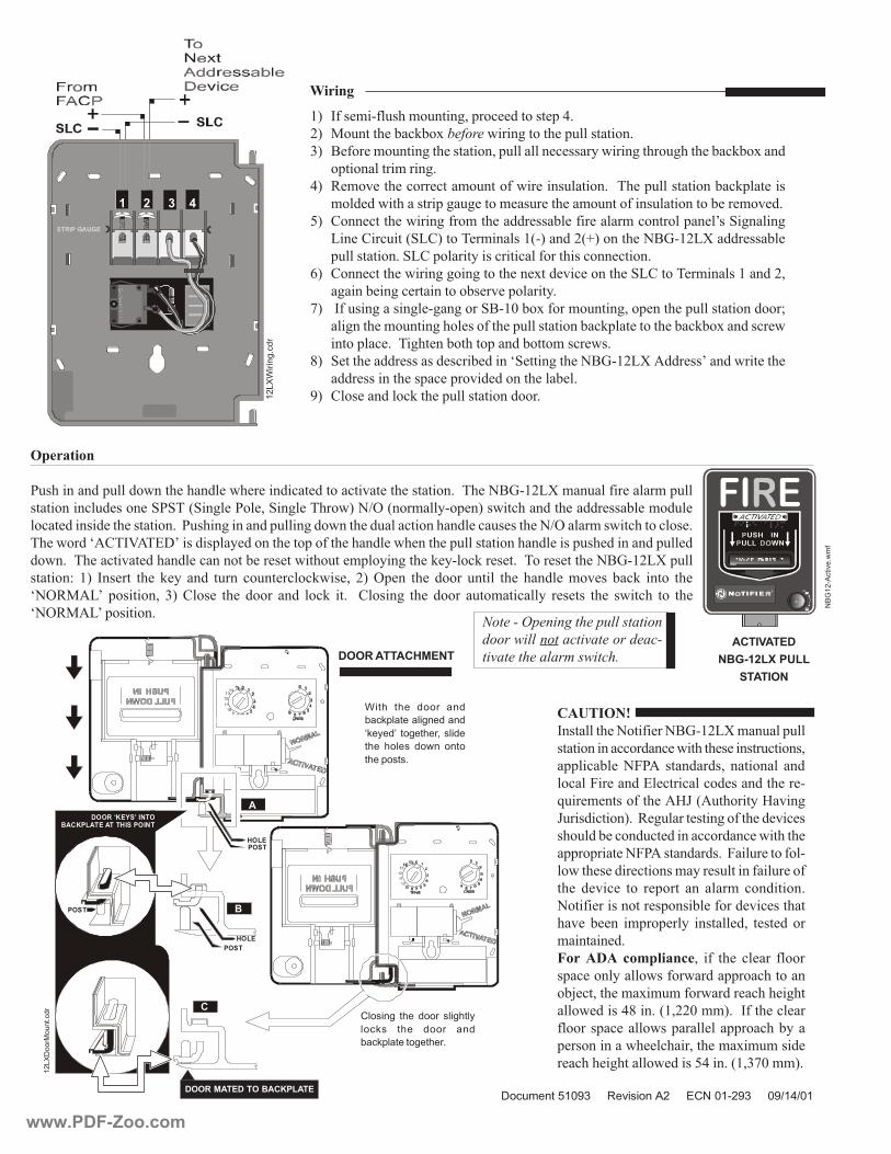
�������������
���������������
����� ��� �����
���� �������
��
��
��
��
�������������
������ ���������
����� ��� �����
���� �������
��
��
��
����
�
�
�
�
����
���������� ���
������������� ���� ��
����
����
���
���
(��������
1�������������������������������������������������������&��������������� �������������$���������������$�����
���������������������"1"��2"��#���1���)�"��#��������3��D%�2���$���������3����������������������������$�����
�������������������������� ��1�����#��������������#�����������������������������������������D%�����$����������������
���������� (�*< �.+!�������������������������������������������������������������������������������������������
���� ����������&��������������������������������������$������#�����,������,������ ��������������������������
�������=� 3� *������ ���� ,��� ���� ����� �����������,����)� 3� %���� ���� ����� ������ ���� ������� $�&��� ���,� ����� ���
��%/' �!� ��������)� 63� (����� ���� ����� ���� ���,� �� � � (�����#� ���� ����� ����$��������� ������� ���� ������� ��� ���
��%/' �!���������
������
��� !"�#��$��
����
)�*+�(,
*���������������������������$����������
���������������������������������������������)
����������� �-1 � ���������)� ��������� ���
������-��������.���������������������������
:����$������������ 9E�2 ���������9�&��#
E�����������3 ��/�#�����������#����������&����
������������������������������������������
�������������-1 ���������� ��-��������������
���������������������$�����������������������
���� ��&���� ��� ������� ��� ����$� ���������
����������������������������������&���������
��&������� �$��������� ���������)� ���������
$���������
%���������&�������)� ��� ���� ������ �����
����������������������������������������
��F���)�����$�;�$�$������������������#��
�����������>8��� �2)��$$3 ��*�����������
�����������������������������������������
����������������������)�����$�;�$�$�����
���������#��������������5>��� �2)6G��$$3
����������������������� ����������������!����������"�#"��
����������������� ��������
����������������������������
������������������������������%���
���������������&����
��� ������
������������������
��
���
���
��
�
5���� ���� ���,� ���
*��0)��������-�������
/0����1� ��-����,.� ����
���� ���� � ��(�� ����
����)� � 2
��� ��-� ���� ���,� ��-����
���0 � ���� ���,� ���
*��0)�������-����,2
3 *����$��������$������#)�����������������>
3 '������������,��;�������������#��������������������
63 �������$������#������������)�������������������������#������#���������,��;����
������������$����#
>3 /�$�&���������������$����������������������� ����������������������,��������
$�������������������#��#�����$������������$���������������������������$�&��
53 (����������������#����$��������������������������$��������������!��"�#�����#
�����(�������2"�(3�������$������2�3�����2H3��������������������������
������������ �"�(�����������������������������������������
B3 (����������������#�#���#����������;����&�����������"�(�������$�����������)
�#��������#�����������������&����������
G3 �*������#������#���#��#����"������;�����$������#)���������������������������I
���#������$������#������������������������������,����������������,��;����������
���������� ����#�����������������������$�������
83 "��������������������������������"�����#������������ ������!��������������
������������������������&�����������������
73 (������������,����������������������
-�����
��&'
5�,��
-2�
�,
��&'
��,:
����2��,
�%
���!�
�����2(
�+
www.PDF-Zoo.com

Agency Listings
Features
• Plug-in design with minimal intrusion into the back box
• Tamper-resistant construction
• Automatic selection of 12- or 24-volt operation at 15 and 15/75 candela
• Field-selectable candela settings on wall units: 15, 15/75, 30, 75, 95, 110, 115, 135, 150, 177, and 185
• Horn rated at 88+ dBA at 16 volts
• Rotary switch for horn tone and three volume selections
• Universal mounting plate for wall units
• Mounting plate shorting spring checks wiring continuity before device installation
• Electrically Compatible with legacy SpectrAlert devices
• Compatible with MDL3 sync module
• Listed for ceiling or wall mounting
The SpectrAlert Advance series offers the most versatile and easy-to-use line of horns, strobes, and horn strobes in the industry. With white and red plastic housings, wall and ceiling mounting options, and plain and FIRE-printed devices, SpectrAlert Advance can meet virtually any application requirement.
Like the entire SpectrAlert Advance product line, wall-mount horns, strobes, and horn strobes include a variety of features that increase their application versatility while simplifying installation. All devices feature plug-in designs with minimal intrusion into the back box, making installations fast and foolproof while virtually eliminating costly and time-consuming ground faults.
To further simplify installation and protect devices from construction damage, SpectrAlert Advance utilizes a universal mounting plate with an onboard shorting spring, so installers can test wiring continuity before the device is installed.
Installers can also easily adapt devices to a suit a wide range of application requirements using field-selectable candela settings, automatic selection of 12- or 24-volt operation, and a rotary switch for horn tones with three volume selections.
Indoor Selectable-Output Horns, Strobes, andHorn Strobes forWall Applications
SpectrAlert® Advance audible visible notification products
are rich with features guaranteed to cut installation times
and maximize profits.
MEA452-05-E3023572
7125-1653:186 (indoor strobes)7125-1653:188 (horn strobes,
chime strobes)7135-1653:189 (horns, chimes)
S4011 (chimes, horn strobes, horns)S5512 (strobes)
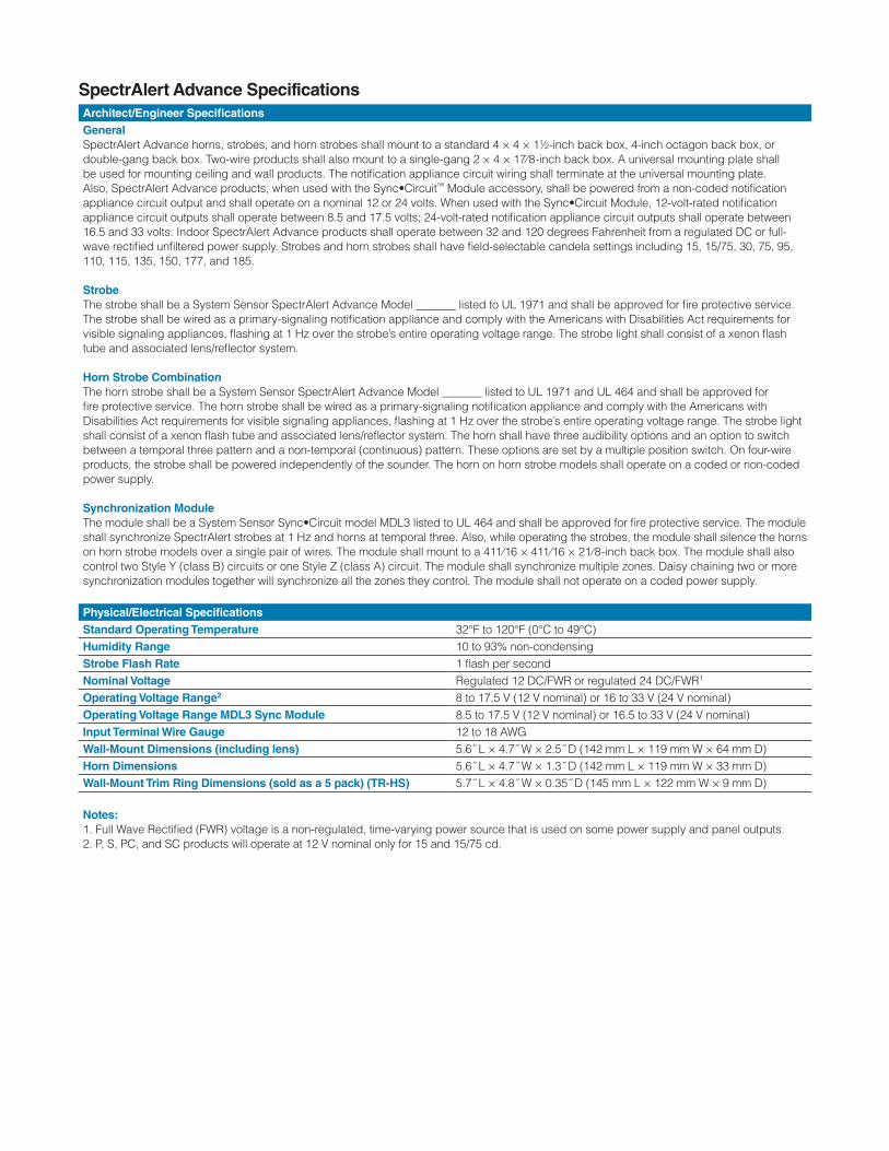
SpectrAlert Advance SpecificationsArchitect/Engineer SpecificationsGeneralSpectrAlert Advance horns, strobes, and horn strobes shall mount to a standard 4 × 4 × 1½-inch back box, 4-inch octagon back box, or double-gang back box. Two-wire products shall also mount to a single-gang 2 × 4 × 17⁄8-inch back box. A universal mounting plate shall be used for mounting ceiling and wall products. The notification appliance circuit wiring shall terminate at the universal mounting plate. Also, SpectrAlert Advance products, when used with the Sync•Circuit™ Module accessory, shall be powered from a non-coded notification appliance circuit output and shall operate on a nominal 12 or 24 volts. When used with the Sync•Circuit Module, 12-volt-rated notification appliance circuit outputs shall operate between 8.5 and 17.5 volts; 24-volt-rated notification appliance circuit outputs shall operate between 16.5 and 33 volts. Indoor SpectrAlert Advance products shall operate between 32 and 120 degrees Fahrenheit from a regulated DC or full-wave rectified unfiltered power supply. Strobes and horn strobes shall have field-selectable candela settings including 15, 15/75, 30, 75, 95, 110, 115, 135, 150, 177, and 185.
StrobeThe strobe shall be a System Sensor SpectrAlert Advance Model _______ listed to UL 1971 and shall be approved for fire protective service. The strobe shall be wired as a primary-signaling notification appliance and comply with the Americans with Disabilities Act requirements for visible signaling appliances, flashing at 1 Hz over the strobe’s entire operating voltage range. The strobe light shall consist of a xenon flash tube and associated lens/reflector system.
Horn Strobe CombinationThe horn strobe shall be a System Sensor SpectrAlert Advance Model _______ listed to UL 1971 and UL 464 and shall be approved for fire protective service. The horn strobe shall be wired as a primary-signaling notification appliance and comply with the Americans with Disabilities Act requirements for visible signaling appliances, flashing at 1 Hz over the strobe’s entire operating voltage range. The strobe light shall consist of a xenon flash tube and associated lens/reflector system. The horn shall have three audibility options and an option to switch between a temporal three pattern and a non-temporal (continuous) pattern. These options are set by a multiple position switch. On four-wire products, the strobe shall be powered independently of the sounder. The horn on horn strobe models shall operate on a coded or non-coded power supply.
Synchronization ModuleThe module shall be a System Sensor Sync•Circuit model MDL3 listed to UL 464 and shall be approved for fire protective service. The module shall synchronize SpectrAlert strobes at 1 Hz and horns at temporal three. Also, while operating the strobes, the module shall silence the horns on horn strobe models over a single pair of wires. The module shall mount to a 411⁄16 × 411⁄16 × 21⁄8-inch back box. The module shall also control two Style Y (class B) circuits or one Style Z (class A) circuit. The module shall synchronize multiple zones. Daisy chaining two or more synchronization modules together will synchronize all the zones they control. The module shall not operate on a coded power supply.
Physical/Electrical SpecificationsStandard Operating Temperature 32°F to 120°F (0°C to 49°C)Humidity Range 10 to 93% non-condensingStrobe Flash Rate 1 flash per secondNominal Voltage Regulated 12 DC/FWR or regulated 24 DC/FWR1
Operating Voltage Range2 8 to 17.5 V (12 V nominal) or 16 to 33 V (24 V nominal)Operating Voltage Range MDL3 Sync Module 8.5 to 17.5 V (12 V nominal) or 16.5 to 33 V (24 V nominal)Input Terminal Wire Gauge 12 to 18 AWGWall-Mount Dimensions (including lens) 5.6˝ L × 4.7˝ W × 2.5˝ D (142 mm L × 119 mm W × 64 mm D)Horn Dimensions 5.6˝ L × 4.7˝ W × 1.3˝ D (142 mm L × 119 mm W × 33 mm D)Wall-Mount Trim Ring Dimensions (sold as a 5 pack) (TR-HS) 5.7˝ L × 4.8˝ W × 0.35˝ D (145 mm L × 122 mm W × 9 mm D)
Notes:1. Full Wave Rectified (FWR) voltage is a non-regulated, time-varying power source that is used on some power supply and panel outputs.2. P, S, PC, and SC products will operate at 12 V nominal only for 15 and 15/75 cd.
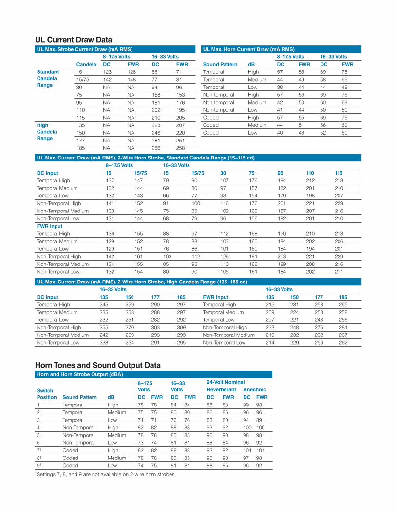
Horn and Horn Strobe Output (dBA)
Switch Position Sound Pattern dB
8–17.5 Volts
16–33Volts
24-Volt NominalReverberant Anechoic
DC FWR DC FWR DC FWR DC FWR1 Temporal High 78 78 84 84 88 88 99 982 Temporal Medium 75 75 80 80 86 86 96 963 Temporal Low 71 71 76 76 83 80 94 894 Non-Temporal High 82 82 88 88 93 92 100 1005 Non-Temporal Medium 78 78 85 85 90 90 98 986 Non-Temporal Low 73 74 81 81 88 84 96 927† Coded High 82 82 88 88 93 92 101 1018† Coded Medium 78 78 85 85 90 90 97 989† Coded Low 74 75 81 81 88 85 96 92
†Settings 7, 8, and 9 are not available on 2-wire horn strobes.
UL Max. Strobe Current Draw (mA RMS)
Candela8–17.5 Volts 16–33 VoltsDC FWR DC FWR
Standard Candela Range
15 123 128 66 7115/75 142 148 77 8130 NA NA 94 9675 NA NA 158 15395 NA NA 181 176110 NA NA 202 195115 NA NA 210 205
HighCandela Range
135 NA NA 228 207150 NA NA 246 220177 NA NA 281 251185 NA NA 286 258
UL Max. Current Draw (mA RMS), 2-Wire Horn Strobe, Standard Candela Range (15–115 cd)
DC Input8–17.5 Volts 16–33 Volts15 15/75 15 15/75 30 75 95 110 115
Temporal High 137 147 79 90 107 176 194 212 218Temporal Medium 132 144 69 80 97 157 182 201 210Temporal Low 132 143 66 77 93 154 179 198 207Non-Temporal High 141 152 91 100 116 176 201 221 229Non-Temporal Medium 133 145 75 85 102 163 187 207 216Non-Temporal Low 131 144 68 79 96 156 182 201 210FWR InputTemporal High 136 155 88 97 112 168 190 210 218Temporal Medium 129 152 78 88 103 160 184 202 206Temporal Low 129 151 76 86 101 160 184 194 201Non-Temporal High 142 161 103 112 126 181 203 221 229Non-Temporal Medium 134 155 85 95 110 166 189 208 216Non-Temporal Low 132 154 80 90 105 161 184 202 211
UL Max. Current Draw (mA RMS), 2-Wire Horn Strobe, High Candela Range (135–185 cd)
DC Input16–33 Volts
FWR Input16–33 Volts
135 150 177 185 135 150 177 185Temporal High 245 259 290 297 Temporal High 215 231 258 265Temporal Medium 235 253 288 297 Temporal Medium 209 224 250 258Temporal Low 232 251 282 292 Temporal Low 207 221 248 256Non-Temporal High 255 270 303 309 Non-Temporal High 233 248 275 281Non-Temporal Medium 242 259 293 299 Non-Temporal Medium 219 232 262 267Non-Temporal Low 238 254 291 295 Non-Temporal Low 214 229 256 262
UL Max. Horn Current Draw (mA RMS)
Sound Pattern dB8–17.5 Volts 16–33 VoltsDC FWR DC FWR
Temporal High 57 55 69 75Temporal Medium 44 49 58 69Temporal Low 38 44 44 48Non-temporal High 57 56 69 75Non-temporal Medium 42 50 60 69Non-temporal Low 41 44 50 50Coded High 57 55 69 75Coded Medium 44 51 56 69Coded Low 40 46 52 50
UL Current Draw Data
Horn Tones and Sound Output Data
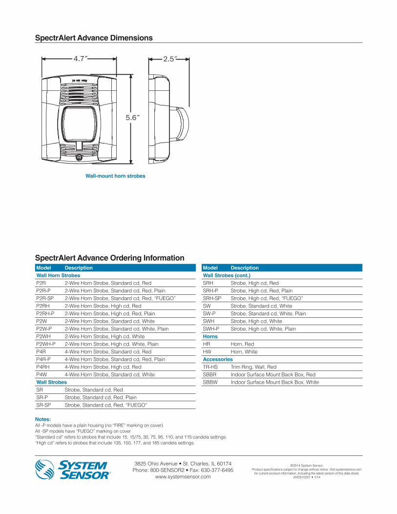
3825 Ohio Avenue • St. Charles, IL 60174 Phone: 800-SENSOR2 • Fax: 630-377-6495
www.systemsensor.com
©2014 System Sensor.Product specifications subject to change without notice. Visit systemsensor.com
for current product information, including the latest version of this data sheet.AVDS10201 • 1/14
SpectrAlert Advance Dimensions
Model DescriptionWall Horn StrobesP2R 2-Wire Horn Strobe, Standard cd, RedP2R-P 2-Wire Horn Strobe, Standard cd, Red, PlainP2R-SP 2-Wire Horn Strobe, Standard cd, Red, “FUEGO”P2RH 2-Wire Horn Strobe, High cd, RedP2RH-P 2-Wire Horn Strobe, High cd, Red, PlainP2W 2-Wire Horn Strobe, Standard cd, WhiteP2W-P 2-Wire Horn Strobe, Standard cd, White, PlainP2WH 2-Wire Horn Strobe, High cd, WhiteP2WH-P 2-Wire Horn Strobe, High cd, White, PlainP4R 4-Wire Horn Strobe, Standard cd, RedP4R-P 4-Wire Horn Strobe, Standard cd, Red, PlainP4RH 4-Wire Horn Strobe, High cd, RedP4W 4-Wire Horn Strobe, Standard cd, WhiteWall StrobesSR Strobe, Standard cd, RedSR-P Strobe, Standard cd, Red, PlainSR-SP Strobe, Standard cd, Red, “FUEGO”
SpectrAlert Advance Ordering Information
Notes:All -P models have a plain housing (no “FIRE” marking on cover)All -SP models have “FUEGO” marking on cover“Standard cd” refers to strobes that include 15, 15/75, 30, 75, 95, 110, and 115 candela settings. “High cd” refers to strobes that include 135, 150, 177, and 185 candela settings.
4.7˝
5.6˝
6.8˝Dia.
2.5˝
2.5˝
Wall-mount horn strobes
Model DescriptionWall Strobes (cont.)SRH Strobe, High cd, RedSRH-P Strobe, High cd, Red, PlainSRH-SP Strobe, High cd, Red, “FUEGO”SW Strobe, Standard cd, WhiteSW-P Strobe, Standard cd, White, PlainSWH Strobe, High cd, WhiteSWH-P Strobe, High cd, White, PlainHornsHR Horn, RedHW Horn, WhiteAccessoriesTR-HS Trim Ring, Wall, RedSBBR Indoor Surface Mount Back Box, RedSBBW Indoor Surface Mount Back Box, White

![Angle Seat Globe Valve, Metal · 550 3 Kv values [m³/h] DN 6 DN 8 DN 10 DN 15 DN 20 DN 25 DN 32 DN 40 DN 50 DN 65 DN 80 Butt weld spigots, DIN 11850 1.6 1.8 2.4 2.4 - - - - - - -](https://img.pdfslide.net/doc/110x75/5f9509c77c6fed50eb12dcff/angle-seat-globe-valve-metal-550-3-kv-values-mh-dn-6-dn-8-dn-10-dn-15-dn-20.jpg)