Embed Size (px)
Citation preview
Cabinet Interfaces and ExternalCables of MGW and RNC
DN0127056Issue 9-4 en
# Nokia Siemens Networks 1 (90)
Nokia Siemens Networks WCDMA RAN, Rel.RU10, System Library, v. 2
The information in this document is subject to change without notice and describes only theproduct defined in the introduction of this documentation. This documentation is intended for theuse of Nokia Siemens Networks customers only for the purposes of the agreement under whichthe document is submitted, and no part of it may be used, reproduced, modified or transmitted inany form or means without the prior written permission of Nokia Siemens Networks. Thedocumentation has been prepared to be used by professional and properly trained personnel,and the customer assumes full responsibility when using it. Nokia Siemens Networks welcomescustomer comments as part of the process of continuous development and improvement of thedocumentation.
The information or statements given in this documentation concerning the suitability, capacity, orperformance of the mentioned hardware or software products are given “as is” and all liabilityarising in connection with such hardware or software products shall be defined conclusively andfinally in a separate agreement between Nokia Siemens Networks and the customer. However,Nokia Siemens Networks has made all reasonable efforts to ensure that the instructionscontained in the document are adequate and free of material errors and omissions. NokiaSiemens Networks will, if deemed necessary by Nokia Siemens Networks, explain issues whichmay not be covered by the document.
Nokia Siemens Networks will correct errors in this documentation as soon as possible. IN NOEVENT WILL NOKIA SIEMENS NETWORKS BE LIABLE FOR ERRORS IN THISDOCUMENTATION OR FOR ANY DAMAGES, INCLUDING BUT NOT LIMITED TO SPECIAL,DIRECT, INDIRECT, INCIDENTAL OR CONSEQUENTIAL OR ANY LOSSES, SUCH AS BUTNOT LIMITED TO LOSS OF PROFIT, REVENUE, BUSINESS INTERRUPTION, BUSINESSOPPORTUNITY OR DATA, THAT MAYARISE FROM THE USE OF THIS DOCUMENT OR THEINFORMATION IN IT.
This documentation and the product it describes are considered protected by copyrights andother intellectual property rights according to the applicable laws.
The wave logo is a trademark of Nokia Siemens Networks Oy. Nokia is a registered trademark ofNokia Corporation. Siemens is a registered trademark of Siemens AG.
Other product names mentioned in this document may be trademarks of their respective owners,and they are mentioned for identification purposes only.
Copyright © Nokia Siemens Networks 2009. All rights reserved.
2 (90) # Nokia Siemens Networks DN0127056Issue 9-4 en
Cabinet Interfaces and External Cables of MGW and RNC
Contents
Contents 3
List of tables 5
List of figures 7
Summary of changes 9
1 Cabinet interfaces and cabling overview 131.1 Power supply interfaces 151.2 Interfaces from the front of the plug-in units 161.3 Interfaces from the back interface units 171.4 Interfaces from the cabling cabinet panels 201.5 Network Management Unit (NEMU) and service terminal interfaces 23
2 Network interfaces 252.1 PDH/TDM connector panels for E1 interfaces 252.1.1 CPETS-G, CPETS-E and CPETS 272.1.2 CPETC-E and CPETC-B 292.1.3 BIE1T-A, BIE1T and BIE1C 312.1.4 E1T48-A and E1C48-A 312.2 STM-1/OC-3 interfaces 322.2.1 Front panels of the NP8S1/-A/-B, NI4S1-B, IW1S1A and IW1S1 plug-in
units 322.2.2 Connector panel CPLC36 352.2.3 Connector panel CPRLC-B 362.3 LAN/Ethernet interfaces 372.3.1 Front panel of the NP2GE/-A plug-in unit 382.3.2 Front panel of the IPFGE plug-in unit 402.3.3 Front panels of the ESA24 and ESA12 plug-in units 422.3.4 Connector panel CPLAN-A 43
3 Maintenance interfaces 453.1 NEMU-specific maintenance interfaces 453.1.1 VDU (VGA) interface pinout 463.1.2 USB interface pinout 463.1.3 Keyboard and mouse pinout 473.1.4 SCSI interface pinout 473.1.5 LAN interface pinout 483.2 Service terminal interface 49
4 Connector panels for external alarm and synchronisationinterfaces 51
4.1 CPAL/-A and CPSAL/-B for alarm interfaces 514.2 CPSY-A, CPSY-B, CPSY and CPSAL/-B for synchronisation
interfaces 554.2.1 External inputs and outputs 57
DN0127056Issue 9-4 en
# Nokia Siemens Networks 3 (90)
Contents
5 Requirement specification for external cables 595.1 E1 and T1 balanced (symmetrical) PCM 595.2 E1 unbalanced (coaxial) cables 625.2.1 E1 unbalanced (coaxial) cables with the CPETC-E panel 625.2.2 E1 unbalanced (coaxial) cables with the BIE1C panels 645.2.3 E1 unbalanced (coaxial) cables with the E1C48-A or CPETC-B panel 655.3 Alarm output to EXAU/-A 675.4 Alarm input cable 715.5 Voltage-controlled alarm input 745.6 Current-controlled alarm input 775.7 Asymmetrical external synchronisation 795.8 Symmetrical external synchronisation 805.9 10Base-T/100Base-TX 835.10 1000Base-T 845.11 Optical STM-1 865.12 1000Base-LX (optical) 875.13 Reference standards and directions 89
4 (90) # Nokia Siemens Networks DN0127056Issue 9-4 en
Cabinet Interfaces and External Cables of MGW and RNC
List of tables
Table 1. Interfaces at the NP2GE/-A plug-in unit 39
Table 2. Interfaces at the IPFGE plug-in unit 41
Table 3. Interfaces at the ESA24/ESA12 units 42
Table 4. Interfaces on the NEMU units 45
Table 5. SVGA interface pinout (D15) 46
Table 6. USB interface pinout (4 pins) 46
Table 7. Keyboard and mouse pinout (6 pins) 47
Table 8. SCSI interface pinout (D68) 47
Table 9. LAN/Ethernet interface pinouts (RJ-45) for CPU, AL2S, CDSP and ESA24/ESA12 plug-in units 48
Table 10. Service terminal interface pinout (RJ-45) 49
Table 11. Voltage-controlled alarm inputs 1 (D37) 52
Table 12. Voltage-controlled alarm inputs 2 (D37) 53
Table 13. Current-controlled alarm inputs (D25) 53
Table 14. Alarm outputs to the External Alarm Unit (EXAU/-A) (D25) 54
Table 15. Alarm outputs (D37) 55
Table 16. External synchronisation inputs and outputs 57
Table 17. Synchronisation interface pinout (RJ-45) 57
Table 18. Synchronisation (OUT 2M) interface pinout (RJ-45) 58
Table 19. Cable CNIA E1 (120 Ω) component codes 60
Table 20. Cable CNIS T1 (100 Ω) component codes 60
Table 21. Cable CNIB (120 Ω) component codes 60
Table 22. RJ-45 connector pinouts (CNIA/CNIS) 60
Table 23. RJ-45 connector pinouts (CNIB) 61
Table 24. Component codes for the unbalanced (coaxial) CPRD cable 63
Table 25. D37 connector pinouts 64
Table 26. Component codes for unbalanced (coaxial) cable 65
Table 27. Component codes for unbalanced (coaxial) cable 66
DN0127056Issue 9-4 en
# Nokia Siemens Networks 5 (90)
List of tables
Table 28. Cable CNDC (version A01) component codes 68
Table 29. Cable CNDC (version A02) component codes 68
Table 30. Connector pinouts for a cable from CPSAL/-B to EXAU/-A or EXAU-A 1 toEXAU-A 2 with a direct cable 69
Table 31. Connector pinouts for a cable from EXAU-A 1 to EXAU-A 2 with acrossover cable 70
Table 32. Component codes for alarm output cable 72
Table 33. Connection pinouts for voltage-controlled alarm input 72
Table 34. Component codes for voltage-controlled alarm input cable 75
Table 35. Connection diagram for voltage-controlled alarm input 75
Table 36. Component codes for cable CNDC 77
Table 37. Connection diagram for current-controlled alarm input 78
Table 38. Component codes for asymmetrical external synchronisation cable 80
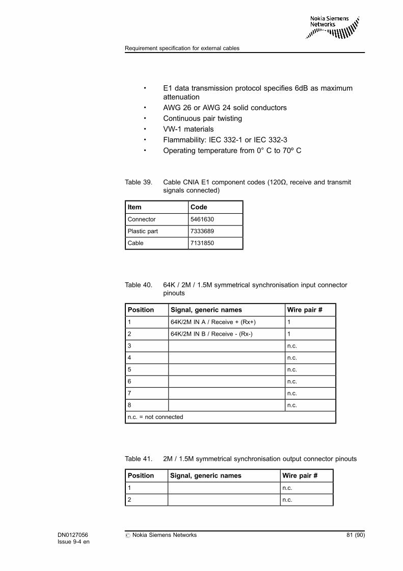
Table 39. Cable CNIA E1 component codes (120Ω, receive and transmit signalsconnected) 81
Table 40. 64K / 2M / 1.5M symmetrical synchronisation input connector pinouts 81
Table 41. 2M / 1.5M symmetrical synchronisation output connector pinouts 81
Table 42. Component codes for CNIX (cross-connected) or CNI (straight) cable 83
Table 43. Cross-connected cable 83
Table 44. Connector pinouts 85
Table 45. Cable types for single-mode optical cables 87
Table 46. Cable types for single-mode optical cables 89
6 (90) # Nokia Siemens Networks DN0127056Issue 9-4 en
Cabinet Interfaces and External Cables of MGW and RNC
List of figures
Figure 1. External interfaces of the MGW 14
Figure 2. External interfaces of the RNC 15
Figure 3. Interfaces from the front of the plug-in units of the MGW and RNC (IPFGEand IW1S1/A used in MGW only) 17
Figure 4. Interfaces from the back interface units of the equipment cabinet: CPSY-A(clock TSS3 0), CPSY-B (clock TSS3 1) and CPAL-A 18
Figure 5. Interfaces from the back interface units of the equipment cabinet: CPRLC-B, BIE1C, BIE1T, and BIE1T-A 20
Figure 6. Cabling cabinet panels 22
Figure 7. Network interfaces on the NEMU plug-in units MCPC2/-A and MCP18/-B 23
Figure 8. Back interface unit and connector panel equipping options 26
Figure 9. Connector panel CPETS-G for the cabling cabinet 27
Figure 10. Connector panel CPETS-E for the cabling cabinet 28
Figure 11. Connector panel CPETS for the cabling cabinet 29
Figure 12. Connector panel CPETC-E for the cabling cabinet 30
Figure 13. Connector panel CPETC-B for the cabling cabinet 31
Figure 14. E1T48-A (upper) and E1C48-A (lower) connector panels for the IC186equipment cabinet 32
Figure 15. Front panel of the NP8S1 plug-in unit 33
Figure 16. Front panel of the NI4S1-B plug-in unit 34
Figure 17. Front panel of the IW1S1/A plug-in unit 35
Figure 18. Connector panel CPLC36 in the cabling cabinet 36
Figure 19. Equipping the connector panel CPRLC-B 37
Figure 20. Front panel of the NP2GE plug-in unit 39
Figure 21. Front panel of the IPFGE plug-in unit 41
Figure 22. Front panel of the ESA24 plug-in unit 42
Figure 23. Connector panel CPLAN-A 43
Figure 24. Connector panels CPAL/-A and CPSAL/-B for alarm interfaces 52
Figure 25. Connector panels CPSY-A, CPSY-B, CPSY and CPSAL/-B for alarm andsynchronisation interfaces 56
DN0127056Issue 9-4 en
# Nokia Siemens Networks 7 (90)
List of figures
Figure 26. Example of CNIA cable assembly 61
Figure 27. Connecting a PCM E1 cable to a connector, CNIS (example) 62
Figure 28. D37 connector body with unbalanced (coaxial) contacts (1=pin,2=ring) 63
Figure 29. Example of E1 multicoaxial cable with SMB connectors 65
Figure 30. Example of E1 multicoaxial cable with BT43 connectors 67
Figure 31. Example of alarm cable to the EXAU/-A 71
Figure 32. Example of alarm output cable 74
Figure 33. Example of voltage-controlled alarm input cable 76
Figure 34. Example of current-controlled alarm input cable 79
Figure 35. Example of asymmetrical external synchronisation cable 80
Figure 36. Example of symmetrical external synchronisation cable 82
Figure 37. Example of LAN cable 84
Figure 38. Example of LAN cable 85
Figure 39. Example of a single-mode optical cable 87
Figure 40. Example of a single-mode optical cable 89
8 (90) # Nokia Siemens Networks DN0127056Issue 9-4 en
Cabinet Interfaces and External Cables of MGW and RNC
Summary of changes
Changes between document issues are cumulative. Therefore, the latestdocument issue contains all changes made to previous issues.
Changes for issue 9-4
Added new plug-in unit variants:
. MX1G6-A, ATM multiplexer 1.6 Gbits/s variant A. New variant forMXU.
. NP2GE-A, network interface and processing 2X1000Base-T/LXvariant A
. NP8S1-A/-B, network interface and processing 8xSTM-1 variant Aor B.
Some corrections and editorial changes.
Changes for issue 9-3
Some editorial changes and minor corrections.
Changes for issue 9-2
Two new panels to ETSI configuration introduced:
. BIE1T-A back interface panel
. CPETS-G connector panel
A new external site cable CNIB for the new panel types BIE1T-A andCPETS-G introduced.
DN0127056Issue 9-4 en
# Nokia Siemens Networks 9 (90)
Summary of changes
Updated information and a graphic regarding the equipping and cabling ofback interface units and connector panels, and the use of cabling cabinetsin RNC.
Some minor editorial changes.
Changes for issue 9-1
In this document, alarm outputs have been corrected to alarm inputs indrawings in chapters 4.1 and 4.2, and in a table header in chapter 5.2.
Changes for issue 9-0
New plug-in units introduced:
. IW1S1A plug-in unit for IWS1E/T with STM-1/OC-3 interfaces fromthe front panel
. NP2GE plug-in unit for NPGE(P) with optical and electrical gigabitEthernet interfaces from the front panel
. NP8S1 plug-in unit for NPS1(P) with STM-1/OC-3 interfaces fromthe front panel
. MX1G6 plug-in unit for MXU with service terminal interface from thefront panel
. SF20H plug-in unit for SFU with service terminal interface from thefront panel
Changes for issue 8-1
Updated the cable information regarding IPFGE plug-in unit: 1000Base-SX was corrected to a single-mode fibre cable 1000Base-LX.
Section Front panel of the IPFGE plug-in unit was updated with output andinput power values of the IPFGE plug-in unit's transceiver.
Section 1000Base-LX (optical) was updated to include the correct single-mode cable information.
Changes for issue 8–0
Document updated and restructured for the U3C and RN2.2 releases.
10 (90) # Nokia Siemens Networks DN0127056Issue 9-4 en
Cabinet Interfaces and External Cables of MGW and RNC
Five new connector panel types introduced: CPAL-A, CPSY-A, and CPSY-B for the rear of the cabinet, as well as the PDH/TDM connector panelsCPETS-E, and CPETC-E added.
Two new cables introduced: the external CPRD cable and the internalCPSM cable.
Changes for issue 7-3
Added information on the RoHS-compliant External Alarm Unit EXAU-A.SectionAlarm output to EXAU/-A updated.
DN0127056Issue 9-4 en
# Nokia Siemens Networks 11 (90)
Summary of changes

12 (90) # Nokia Siemens Networks DN0127056Issue 9-4 en
Cabinet Interfaces and External Cables of MGW and RNC
1 Cabinet interfaces and cabling overview
Cabinet Interfaces and External Cables of MGW and RNC containsinformation on the network interfaces and cables for IPA2800 networkelements, namely Multimedia Gateway (MGW) and Radio NetworkController (RNC). This document applies to all releases of both MGW andRNC.
The external cables of the MGW and RNC connect the network element toits environment, the mobile network it is used in. The MGW and RNCnetwork elements have the following interfaces to the environment:
. Power supply interfaces
. PDH/E1 T1 interfaces
. SDH/STM-1 OC-3 interfaces
. External synchronisation and alarm inputs and outputs
. LAN/Ethernet interfaces
. Service terminal interfaces from various plug-in units (for temporaryservice operations; not covered by this manual)
. Interfaces of the Network Management Unit (NEMU) to accessoriesand peripherals: mouse, keyboard, and VDU
The external cables connect to the front panels of the plug-in units, to theback interface units at the rear of the equipment cabinets, or to theconnector panels in the cabling cabinet.
For more information, see the Cable Lists, Equipment Lists, InstallationSite Requirements for MGW and RNC and Engineering Descriptions.
DN0127056Issue 9-4 en
# Nokia Siemens Networks 13 (90)
Cabinet interfaces and cabling overview
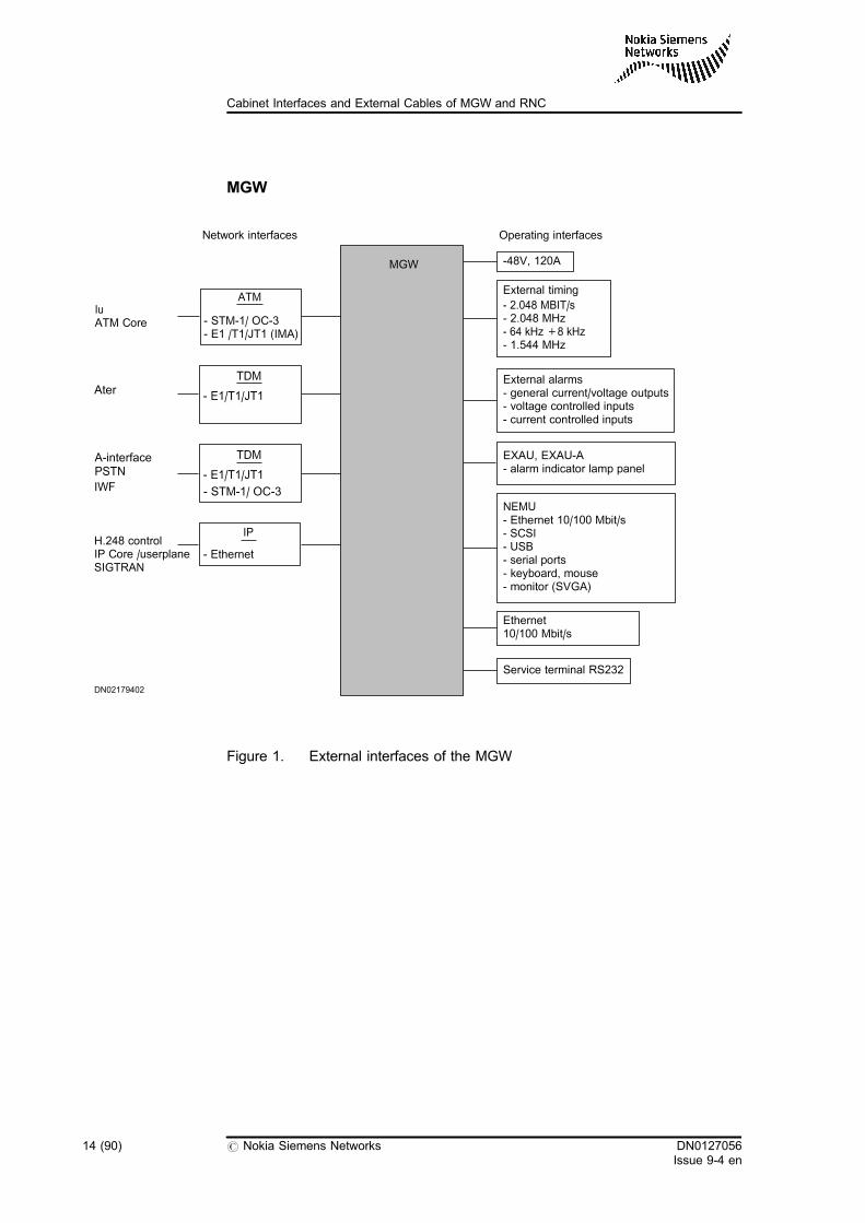
MGW
Figure 1. External interfaces of the MGW
External timing
- 2.048 MBIT/s- 2.048 MHz- 64 kHz +8 kHz- 1.544 MHz
Service terminal RS232
-48V, 120A
NEMU- Ethernet 10/100 Mbit/s- SCSI- USB- serial ports- keyboard, mouse- monitor (SVGA)
DN02179402
External alarms- general current/voltage outputs- voltage controlled inputs- current controlled inputs
MGW
Network interfaces Operating interfaces
EXAU, EXAU-A- alarm indicator lamp panel
Ethernet10/100 Mbit/s
- STM-1/ OC-3- E1 /T1/JT1 (IMA)
IuATM Core
ATM
A-interfacePSTN
IWF
TDM
- E1/T1/JT1
- STM-1/ OC-3
H.248 controlIP Core /userplaneSIGTRAN
IP
- Ethernet
AterTDM
- E1/T1/JT1
14 (90) # Nokia Siemens Networks DN0127056Issue 9-4 en
Cabinet Interfaces and External Cables of MGW and RNC
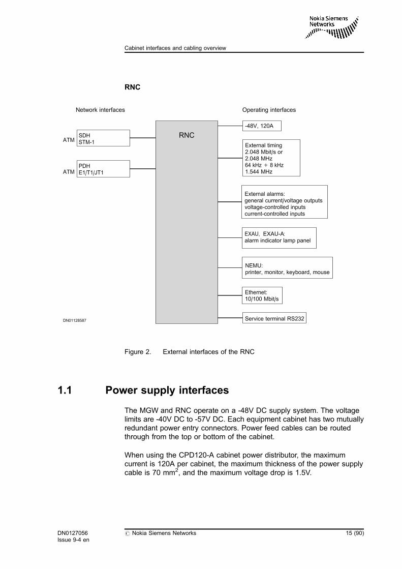
RNC
Figure 2. External interfaces of the RNC
1.1 Power supply interfaces
The MGW and RNC operate on a -48V DC supply system. The voltagelimits are -40V DC to -57V DC. Each equipment cabinet has two mutuallyredundant power entry connectors. Power feed cables can be routedthrough from the top or bottom of the cabinet.
When using the CPD120-A cabinet power distributor, the maximumcurrent is 120A per cabinet, the maximum thickness of the power supplycable is 70 mm2, and the maximum voltage drop is 1.5V.
SDHSTM-1
PDHE1/T1/JT1
ATM
ATM
Network interfaces
DN01128587
RNC
Operating interfaces
-48V, 120A
External alarms:general current/voltage outputsvoltage-controlled inputscurrent-controlled inputs
EXAU, EXAU-A:alarm indicator lamp panel
NEMU:printer, monitor, keyboard, mouse
Ethernet:10/100 Mbit/s
Service terminal RS232
External timing2.048 Mbit/s or2.048 MHz64 kHz + 8 kHz1.544 MHz
DN0127056Issue 9-4 en
# Nokia Siemens Networks 15 (90)
Cabinet interfaces and cabling overview
When using the CPD80-B/-A cabinet power distributor, the maximumcurrent is 80A per cabinet, the maximum thickness of the power supplycable is 50 mm2, and the maximum voltage drop is 1.5V.
1.2 Interfaces from the front of the plug-in units
The front panels of the plug-in units house several connectors:
. STM-1/OC-3 interfaces from NP8S1/-A/-B (NPS1P/NPS1), NI4S1-B(NIS1P/NIS1) and IW1S1/A (IW1SE, IWS1T; used in MGW only)
. Optical LAN 1000 BASE-LX (NPGEP/NPGE), IPGOP), electricalLAN 1000 BASE-T (NPGEP/NPGE), IPGEP), and electrical LAN100 BASE-T (IPFEP) interfaces from IPFGE (IPNIUP used in MGWonly)
. LAN 100 BASE-T interface(s) from the ESA24 plug-in unit (two frontpanel connectors for external use)
. LAN 100 BASE-T interface(s) from the ESA12 plug-in unit (twoupper front panel connectors for external use)
16 (90) # Nokia Siemens Networks DN0127056Issue 9-4 en
Cabinet Interfaces and External Cables of MGW and RNC
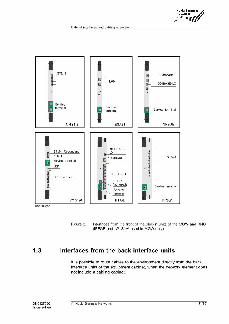
Figure 3. Interfaces from the front of the plug-in units of the MGW and RNC(IPFGE and IW1S1/A used in MGW only)
1.3 Interfaces from the back interface units
It is possible to route cables to the environment directly from the backinterface units of the equipment cabinet, when the network element doesnot include a cabling cabinet.
LAN
Serviceterminal
ESA24
100BASE-T
LAN(not used)
Serviceterminal
IPFGE
1000BASE-T
1000BASE-LX
STM-1
Serviceterminal
NI4S1-B
DN02179683
LED
LAN (not used)
Service terminal
STM-1
STM-1 Redundant
IW1S1/A
NP2GE
Service terminal
1000BASE-LX
1000BASE-T
NP8S1
Service terminal
STM-1
DN0127056Issue 9-4 en
# Nokia Siemens Networks 17 (90)
Cabinet interfaces and cabling overview
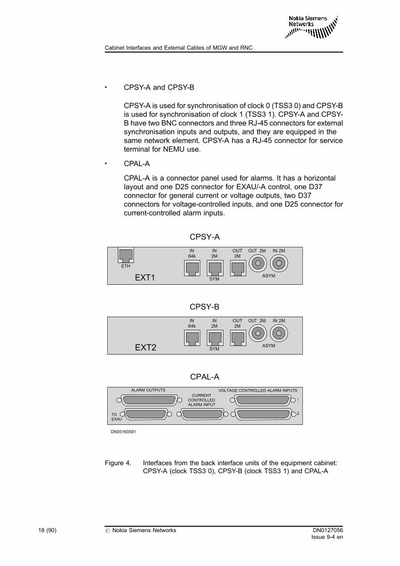
. CPSY-A and CPSY-B
CPSY-A is used for synchronisation of clock 0 (TSS3 0) and CPSY-Bis used for synchronisation of clock 1 (TSS3 1). CPSY-A and CPSY-B have two BNC connectors and three RJ-45 connectors for externalsynchronisation inputs and outputs, and they are equipped in thesame network element. CPSY-A has a RJ-45 connector for serviceterminal for NEMU use.
. CPAL-A
CPAL-A is a connector panel used for alarms. It has a horizontallayout and one D25 connector for EXAU/-A control, one D37connector for general current or voltage outputs, two D37connectors for voltage-controlled inputs, and one D25 connector forcurrent-controlled alarm inputs.
Figure 4. Interfaces from the back interface units of the equipment cabinet:CPSY-A (clock TSS3 0), CPSY-B (clock TSS3 1) and CPAL-A
IN64k
IN2M
OUT2M
OUT 2M IN 2M
SYMASYMEXT2
IN64k
IN2M
OUT2M
OUT 2M IN 2M
SYMASYMEXT1
CPSY-A
CPSY-B
CPAL-A
TOEXAU
ETH
ALARM OUTPUTS
CURRENTCONTROLLEDALARM INPUT
VOLTAGE CONTROLLED ALARM INPUTS
1
2
DN05160581
18 (90) # Nokia Siemens Networks DN0127056Issue 9-4 en
Cabinet Interfaces and External Cables of MGW and RNC
. CPSAL-B (in RNC only)
A connector panel type for external synchronisation and HW alarminterfaces.
. CPRLC-B (in RNC only)
A connector panel for STM-1/OC-3 interfaces with 16 pieces of LCconnectors.
. BIE1T
A back interface unit for E1/T1 balanced interfaces with 16 pieces ofRJ-45 connectors.
. BIE1T-A (in MGW only)
A back interface unit for E1 balanced interfaces with 8 pieces of RJ-45 connectors, two E1 interfaces via each RJ-45 connector.
. BIE1C
A back interface unit for E1 unbalanced interfaces with 32 pieces ofSMB connectors.
DN0127056Issue 9-4 en
# Nokia Siemens Networks 19 (90)
Cabinet interfaces and cabling overview
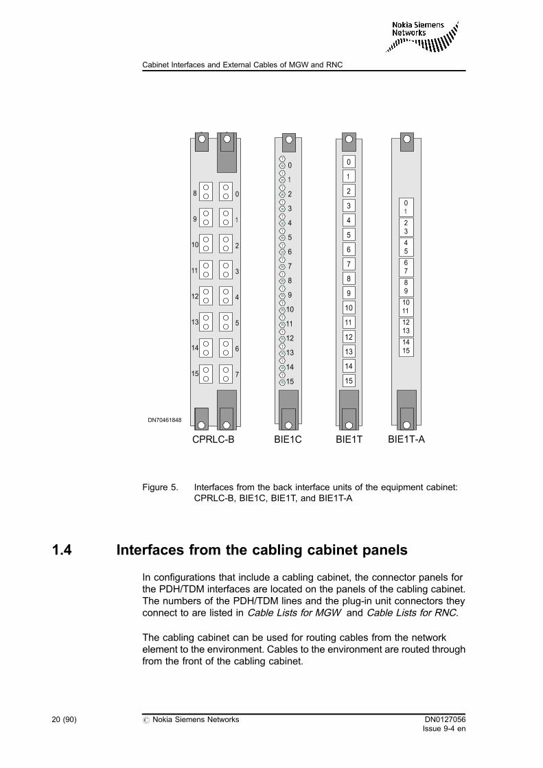
Figure 5. Interfaces from the back interface units of the equipment cabinet:CPRLC-B, BIE1C, BIE1T, and BIE1T-A
1.4 Interfaces from the cabling cabinet panels
In configurations that include a cabling cabinet, the connector panels forthe PDH/TDM interfaces are located on the panels of the cabling cabinet.The numbers of the PDH/TDM lines and the plug-in unit connectors theyconnect to are listed in Cable Lists for MGW and Cable Lists for RNC.
The cabling cabinet can be used for routing cables from the networkelement to the environment. Cables to the environment are routed throughfrom the front of the cabling cabinet.
BIE1T-A
01
23
45
67
89
1011
1213
1415
CPRLC-B BIE1C BIE1T
0
1
2
3
4
5
6
7
8
9
10
11
12
13
14
15
0
1
2
3
4
5
6
7
8
9
10
11
12
13
14
15
--
0
1
2
3
4
5
6
7
8
9
10
11
12
13
14
15
DN70461848
20 (90) # Nokia Siemens Networks DN0127056Issue 9-4 en
Cabinet Interfaces and External Cables of MGW and RNC
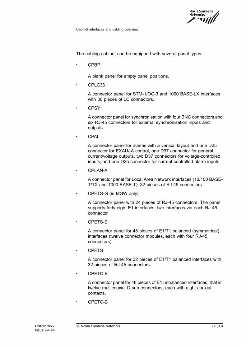
The cabling cabinet can be equipped with several panel types:
. CPBP
A blank panel for empty panel positions.
. CPLC36
A connector panel for STM-1/OC-3 and 1000 BASE-LX interfaceswith 36 pieces of LC connectors.
. CPSY
A connector panel for synchronisation with four BNC connectors andsix RJ-45 connectors for external synchronisation inputs andoutputs.
. CPAL
A connector panel for alarms with a vertical layout and one D25connector for EXAU/-A control, one D37 connector for generalcurrent/voltage outputs, two D37 connectors for voltage-controlledinputs, and one D25 connector for current-controlled alarm inputs.
. CPLAN-A
A connector panel for Local Area Network interfaces (10/100 BASE-T/TX and 1000 BASE-T), 32 pieces of RJ-45 connectors.
. CPETS-G (in MGW only)
A connector panel with 24 pieces of RJ-45 connectors. The panelsupports forty-eight E1 interfaces, two interfaces via each RJ-45connector.
. CPETS-E
A connector panel for 48 pieces of E1/T1 balanced (symmetrical)interfaces (twelve connector modules, each with four RJ-45connectors).
. CPETS
A connector panel for 32 pieces of E1/T1 balanced interfaces with32 pieces of RJ-45 connectors.
. CPETC-E
A connector panel for 48 pieces of E1 unbalanced interfaces, that is,twelve multicoaxial D-sub connectors, each with eight coaxialcontacts.
. CPETC-B
DN0127056Issue 9-4 en
# Nokia Siemens Networks 21 (90)
Cabinet interfaces and cabling overview
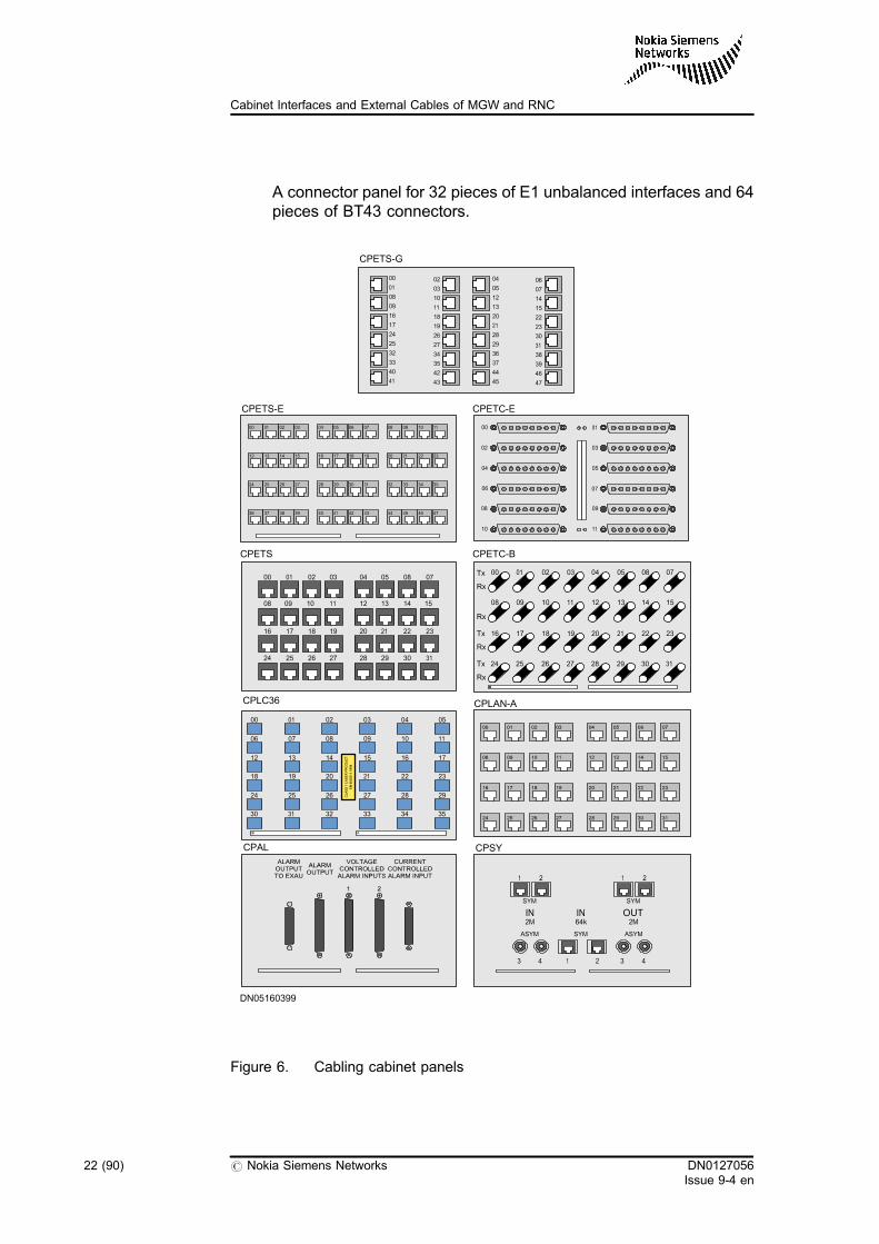
A connector panel for 32 pieces of E1 unbalanced interfaces and 64pieces of BT43 connectors.
Figure 6. Cabling cabinet panels
CPETC-BCPETS
CPLAN-ACPLC36
CPAL CPSY
00
06
12
18
24
30
01
07
13
19
25
31
02
08
14
20
26
32
03
09
15
21
27
33
04
10
16
22
28
34
05
11
17
23
29
35
00 01 02 03 04 05 08 07
08 09 10 11 12 13 14 15
16 17 18 19 20 21 22 23
24 25 26 27 28 29 30 31
Tx
Rx
Rx
Tx
Rx
Tx
Rx
00 01 02 03 04 05 08 07
08 09 10 11 12 13 14 15
16 17 18 19 20 21 22 23
24 25 26 27 28 29 30 31
DN05160399
IN OUT2M 2M
IN64k
ASYM ASYMSYM
SYM SYM
1 2 1 2
3 4 3 41 2
CPETC-E
00
02
04
06
08
10
01
03
05
07
09
11
CPETS-E
00 01 02 03 04 05 06 07 08 09 10 11
12 13 14 15 16 17 18 19 20 21 22 23
24 25 26 27 28 29 30 31 32 33 34 35
36 37 38 39 40 41 42 43 44 45 46 47
CPETS-G
00
01
08
09
16
17
24
25
32
33
40
41
02
03
10
11
18
19
26
27
34
35
42
43
04
05
12
13
20
21
28
29
36
37
44
45
06
07
14
15
22
23
30
31
38
39
46
47
22 (90) # Nokia Siemens Networks DN0127056Issue 9-4 en
Cabinet Interfaces and External Cables of MGW and RNC
1.5 Network Management Unit (NEMU) and serviceterminal interfaces
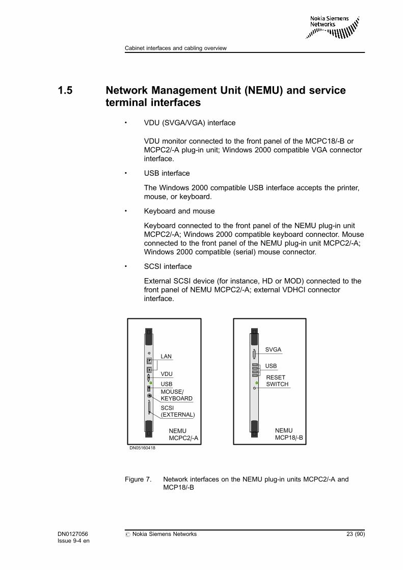
. VDU (SVGA/VGA) interface
VDU monitor connected to the front panel of the MCPC18/-B orMCPC2/-A plug-in unit; Windows 2000 compatible VGA connectorinterface.
. USB interface
The Windows 2000 compatible USB interface accepts the printer,mouse, or keyboard.
. Keyboard and mouse
Keyboard connected to the front panel of the NEMU plug-in unitMCPC2/-A; Windows 2000 compatible keyboard connector. Mouseconnected to the front panel of the NEMU plug-in unit MCPC2/-A;Windows 2000 compatible (serial) mouse connector.
. SCSI interface
External SCSI device (for instance, HD or MOD) connected to thefront panel of NEMU MCPC2/-A; external VDHCI connectorinterface.
Figure 7. Network interfaces on the NEMU plug-in units MCPC2/-A andMCP18/-B
DN05160418
NEMUMCPC2/-A
LAN
VDU
USB
MOUSE/KEYBOARD
SCSI(EXTERNAL)
NEMUMCP18/-B
SVGA
USB
RESETSWITCH
DN0127056Issue 9-4 en
# Nokia Siemens Networks 23 (90)
Cabinet interfaces and cabling overview

24 (90) # Nokia Siemens Networks DN0127056Issue 9-4 en
Cabinet Interfaces and External Cables of MGW and RNC
2 Network interfaces
2.1 PDH/TDM connector panels for E1 interfaces
There are five types of connector panels for the cabling cabinet:
. CPETS-G for E1 balanced PDH interfaces, ETSI
. CPETS-E for E1/T1 balanced PDH lines, ANSI
. CPETS for E1/T1 balanced PDH lines
. CPETC-E for E1 unbalanced PDH lines
. CPETC-B for E1 unbalanced PDH lines
There are three types of back interface units for connecting PDH lines:
. BIE1T-A for E1 balanced PDH interfaces, ETSI
. BIE1T for E1/T1 balanced PDH interfaces, ANSI
. BIE1C for E1 unbalanced PDH interfaces, ETSI
The back interface units BIE1T-A, BIE1Tand BIE1C are located at the rearof the equipment cabinet, directly behind the NIWU or NIP1 units that theyserve.
For information on cabling, see section Requirement specification forexternal cables.
DN0127056Issue 9-4 en
# Nokia Siemens Networks 25 (90)
Network interfaces
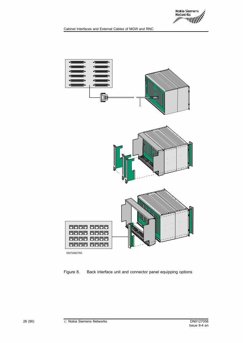
Figure 8. Back interface unit and connector panel equipping options
DN70462765
26 (90) # Nokia Siemens Networks DN0127056Issue 9-4 en
Cabinet Interfaces and External Cables of MGW and RNC
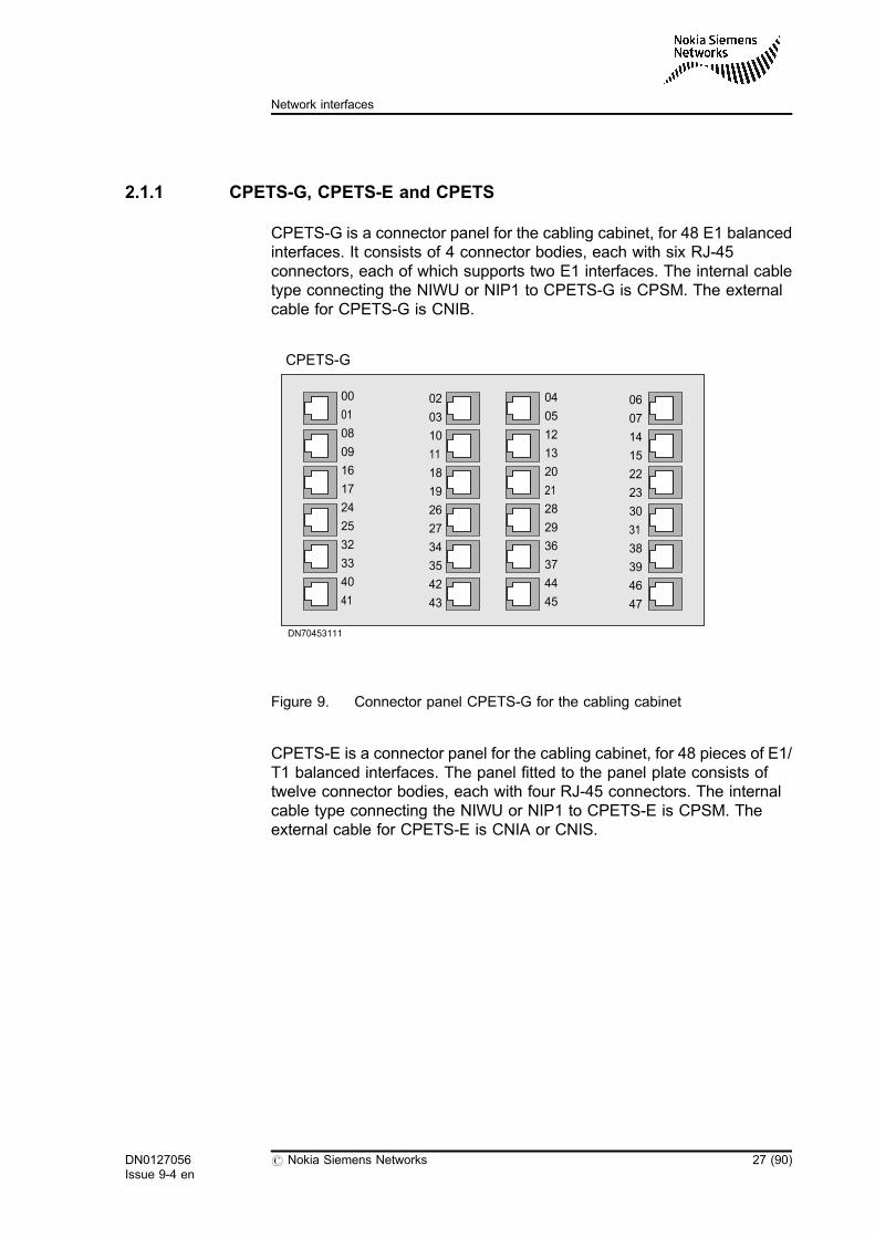
2.1.1 CPETS-G, CPETS-E and CPETS
CPETS-G is a connector panel for the cabling cabinet, for 48 E1 balancedinterfaces. It consists of 4 connector bodies, each with six RJ-45connectors, each of which supports two E1 interfaces. The internal cabletype connecting the NIWU or NIP1 to CPETS-G is CPSM. The externalcable for CPETS-G is CNIB.
Figure 9. Connector panel CPETS-G for the cabling cabinet
CPETS-E is a connector panel for the cabling cabinet, for 48 pieces of E1/T1 balanced interfaces. The panel fitted to the panel plate consists oftwelve connector bodies, each with four RJ-45 connectors. The internalcable type connecting the NIWU or NIP1 to CPETS-E is CPSM. Theexternal cable for CPETS-E is CNIA or CNIS.
DN70453111
CPETS-G
00
01
08
09
16
17
24
25
32
33
40
41
02
03
10
11
18
19
26
27
34
35
42
43
04
05
12
13
20
21
28
29
36
37
44
45
06
07
14
15
22
23
30
31
38
39
46
47
DN0127056Issue 9-4 en
# Nokia Siemens Networks 27 (90)
Network interfaces
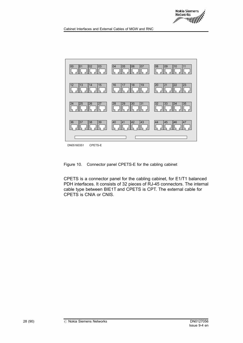
Figure 10. Connector panel CPETS-E for the cabling cabinet
CPETS is a connector panel for the cabling cabinet, for E1/T1 balancedPDH interfaces. It consists of 32 pieces of RJ-45 connectors. The internalcable type between BIE1T and CPETS is CPT. The external cable forCPETS is CNIA or CNIS.
00
DN05160351
01 02 03 04 05 06 07 08 09 10 11
12 13 14 15 16 17 18 19 20 21 22 23
24 25 26 27 28 29 30 31 32 33 34 35
36 37 38 39 40 41 42 43 44 45 46 47
CPETS-E
28 (90) # Nokia Siemens Networks DN0127056Issue 9-4 en
Cabinet Interfaces and External Cables of MGW and RNC
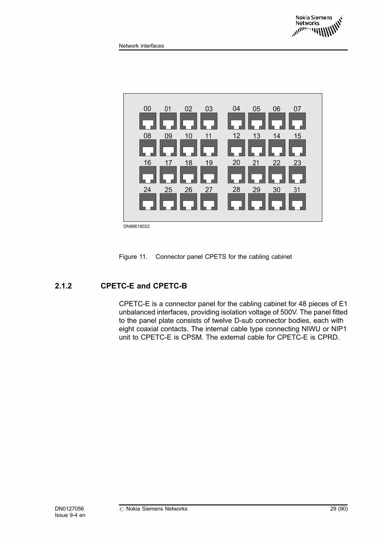
Figure 11. Connector panel CPETS for the cabling cabinet
2.1.2 CPETC-E and CPETC-B
CPETC-E is a connector panel for the cabling cabinet for 48 pieces of E1unbalanced interfaces, providing isolation voltage of 500V. The panel fittedto the panel plate consists of twelve D-sub connector bodies, each witheight coaxial contacts. The internal cable type connecting NIWU or NIP1unit to CPETC-E is CPSM. The external cable for CPETC-E is CPRD.
DN98618022
00
08
16
24
01
09
17
25
02
10
18
26
03
11
19
27
04
12
20
28
05
13
21
29
06
14
22
30
07
15
23
31
DN0127056Issue 9-4 en
# Nokia Siemens Networks 29 (90)
Network interfaces
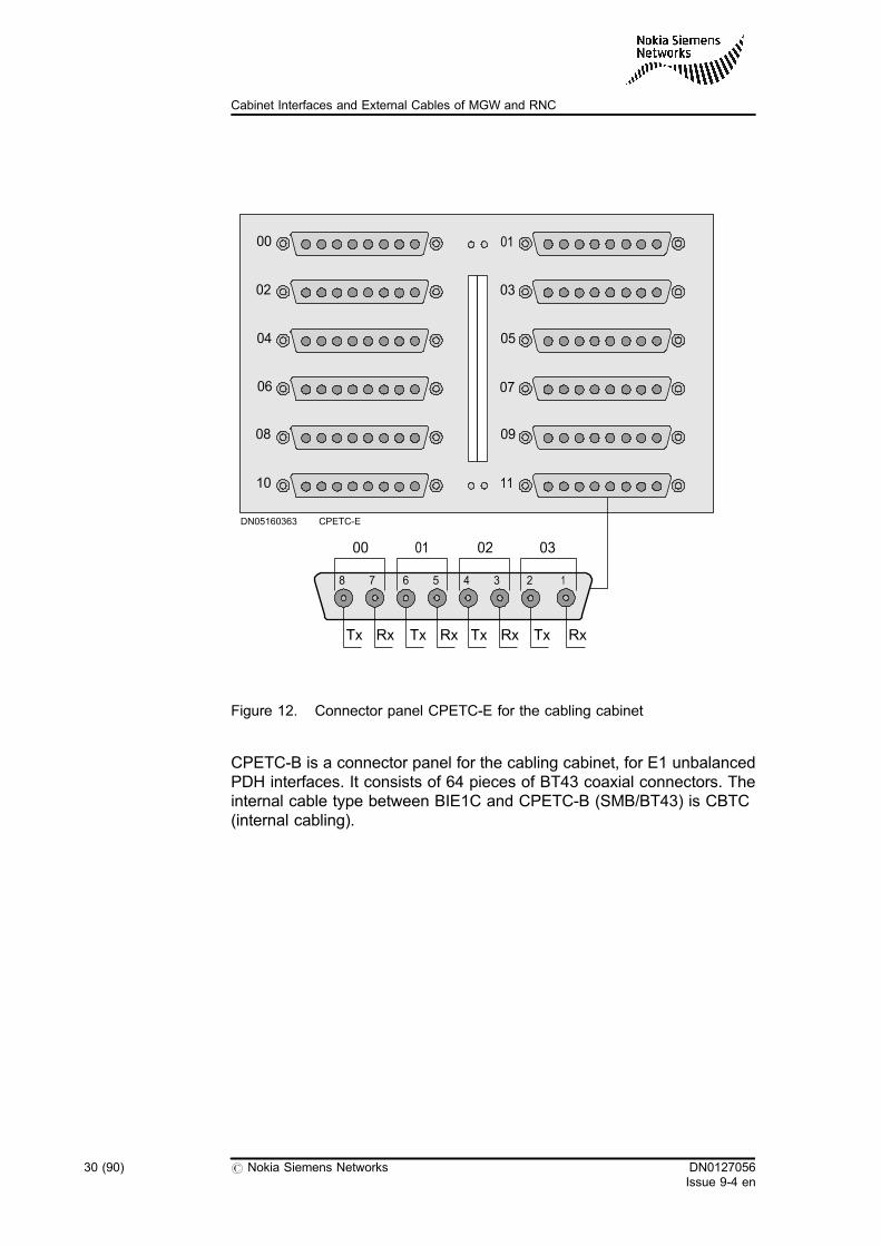
Figure 12. Connector panel CPETC-E for the cabling cabinet
CPETC-B is a connector panel for the cabling cabinet, for E1 unbalancedPDH interfaces. It consists of 64 pieces of BT43 coaxial connectors. Theinternal cable type between BIE1C and CPETC-B (SMB/BT43) is CBTC(internal cabling).
00
02
04
06
08
10
01
03
05
07
09
11
DN05160363 CPETC-E
RxTx RxTx RxTx RxTx
00
78 56 34 12
01 02 03
30 (90) # Nokia Siemens Networks DN0127056Issue 9-4 en
Cabinet Interfaces and External Cables of MGW and RNC
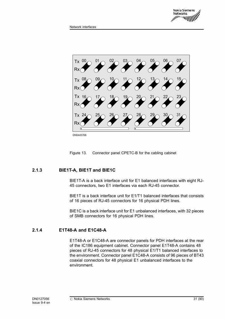
Figure 13. Connector panel CPETC-B for the cabling cabinet
2.1.3 BIE1T-A, BIE1T and BIE1C
BIE1T-A is a back interface unit for E1 balanced interfaces with eight RJ-45 connectors, two E1 interfaces via each RJ-45 connector.
BIE1T is a back interface unit for E1/T1 balanced interfaces that consistsof 16 pieces of RJ-45 connectors for 16 physical PDH lines.
BIE1C is a back interface unit for E1 unbalanced interfaces, with 32 piecesof SMB connectors for 16 physical PDH lines.
2.1.4 E1T48-A and E1C48-A
E1T48-A or E1C48-A are connector panels for PDH interfaces at the rearof the IC186 equipment cabinet. Connector panel E1T48-A contains 48pieces of RJ-45 connectors for 48 physical E1/T1 balanced interfaces tothe environment. Connector panel E1C48-A consists of 96 pieces of BT43coaxial connectors for 48 physical E1 unbalanced interfaces to theenvironment.
Tx
Rx
Tx
Rx
Tx
Rx
Tx
Rx
00
08
16
24
01
09
17
25
02
10
18
26
03
11
19
27
04
12
20
28
05
13
21
29
06
14
22
30
07
15
23
31
DN0445768
DN0127056Issue 9-4 en
# Nokia Siemens Networks 31 (90)
Network interfaces
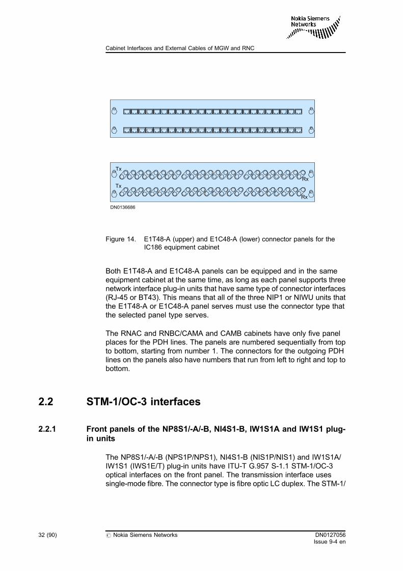
Figure 14. E1T48-A (upper) and E1C48-A (lower) connector panels for theIC186 equipment cabinet
Both E1T48-A and E1C48-A panels can be equipped and in the sameequipment cabinet at the same time, as long as each panel supports threenetwork interface plug-in units that have same type of connector interfaces(RJ-45 or BT43). This means that all of the three NIP1 or NIWU units thatthe E1T48-A or E1C48-A panel serves must use the connector type thatthe selected panel type serves.
The RNAC and RNBC/CAMA and CAMB cabinets have only five panelplaces for the PDH lines. The panels are numbered sequentially from topto bottom, starting from number 1. The connectors for the outgoing PDHlines on the panels also have numbers that run from left to right and top tobottom.
2.2 STM-1/OC-3 interfaces
2.2.1 Front panels of the NP8S1/-A/-B, NI4S1-B, IW1S1A and IW1S1 plug-in units
The NP8S1/-A/-B (NPS1P/NPS1), NI4S1-B (NIS1P/NIS1) and IW1S1A/IW1S1 (IWS1E/T) plug-in units have ITU-T G.957 S-1.1 STM-1/OC-3optical interfaces on the front panel. The transmission interface usessingle-mode fibre. The connector type is fibre optic LC duplex. The STM-1/
DN0136686
Tx
Tx
Rx
Rx
32 (90) # Nokia Siemens Networks DN0127056Issue 9-4 en
Cabinet Interfaces and External Cables of MGW and RNC
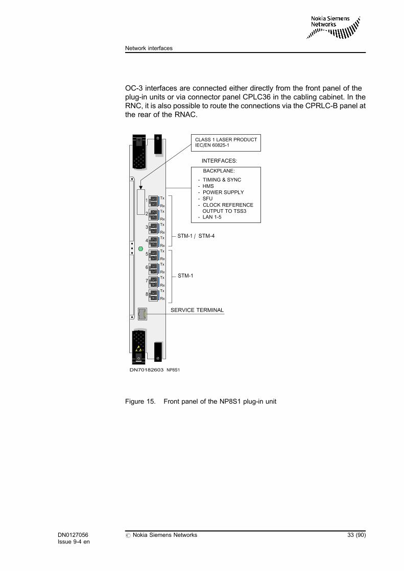
OC-3 interfaces are connected either directly from the front panel of theplug-in units or via connector panel CPLC36 in the cabling cabinet. In theRNC, it is also possible to route the connections via the CPRLC-B panel atthe rear of the RNAC.
Figure 15. Front panel of the NP8S1 plug-in unit
DN70182603 NP8S1
1
2
3
4
5
6
7
8
STM-1 / STM-4
Tx
Rx
Tx
Rx
Tx
Rx
Tx
Rx
Tx
Rx
Tx
Rx
Tx
Rx
Tx
Rx
STM-1
SERVICE TERMINAL
INTERFACES:
BACKPLANE:
- TIMING & SYNC
- HMS- POWER SUPPLY- SFU
- CLOCK REFERENCEOUTPUT TO TSS3
- LAN 1-5
CLASS 1 LASER PRODUCTIEC/EN 60825-1
DN0127056Issue 9-4 en
# Nokia Siemens Networks 33 (90)
Network interfaces
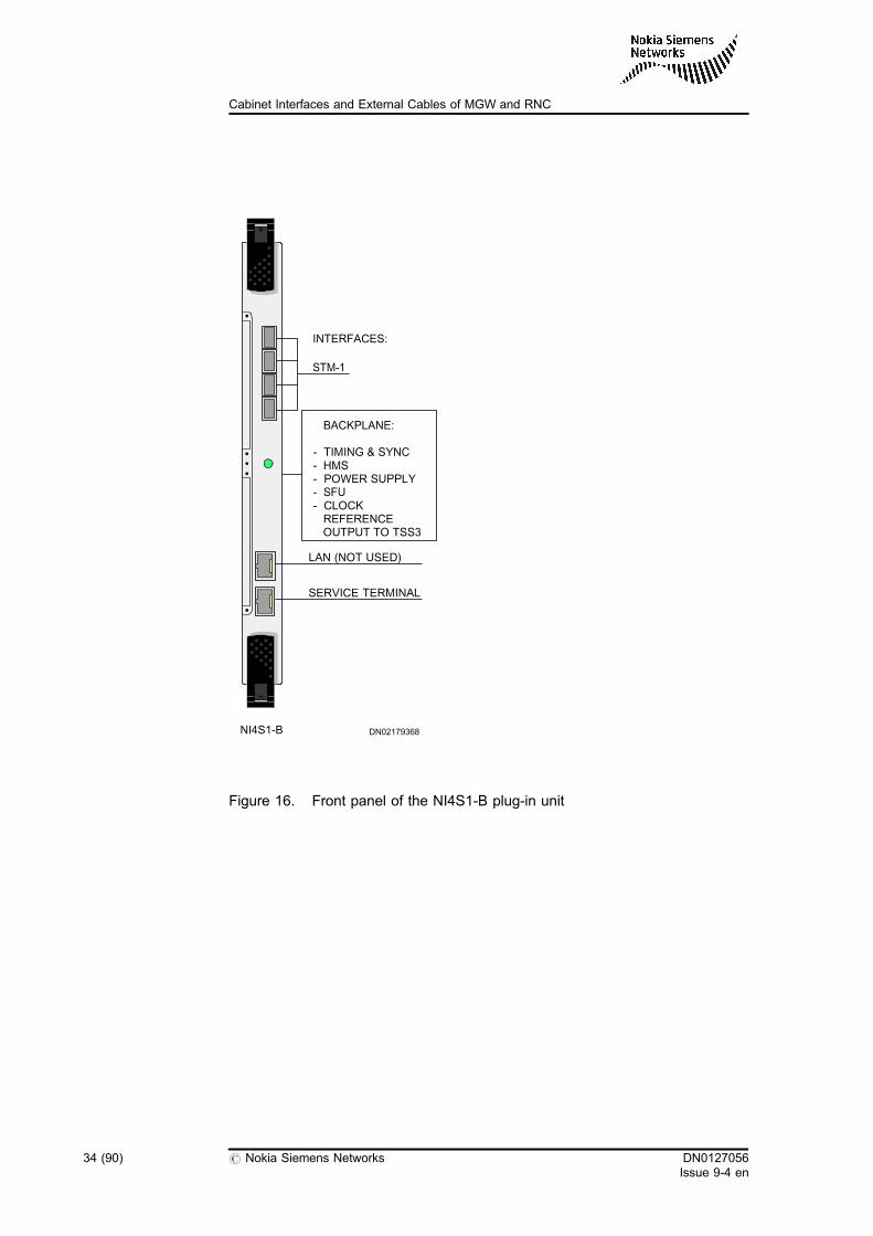
Figure 16. Front panel of the NI4S1-B plug-in unit
NI4S1-B DN02179368
INTERFACES:
BACKPLANE:
- TIMING & SYNC- HMS- POWER SUPPLY- SFU- CLOCKREFERENCEOUTPUT TO TSS3
LAN (NOT USED)
STM-1
SERVICE TERMINAL
34 (90) # Nokia Siemens Networks DN0127056Issue 9-4 en
Cabinet Interfaces and External Cables of MGW and RNC
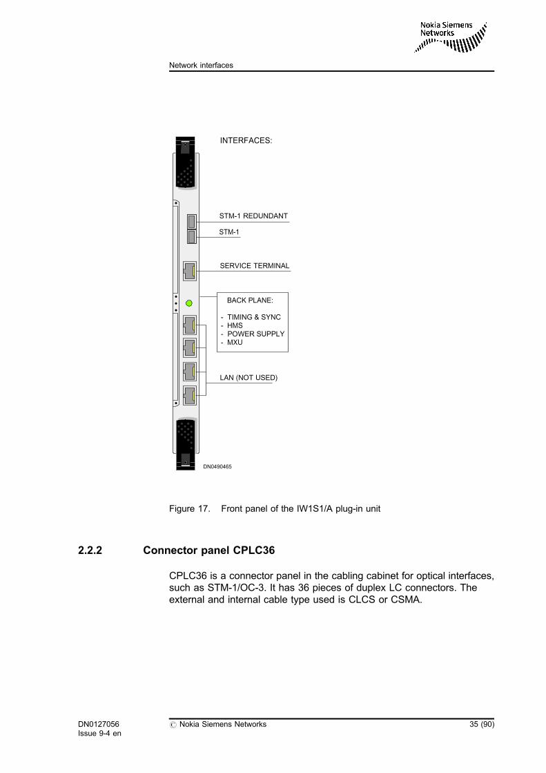
Figure 17. Front panel of the IW1S1/A plug-in unit
2.2.2 Connector panel CPLC36
CPLC36 is a connector panel in the cabling cabinet for optical interfaces,such as STM-1/OC-3. It has 36 pieces of duplex LC connectors. Theexternal and internal cable type used is CLCS or CSMA.
DN0490465
LAN (NOT USED)
SERVICE TERMINAL
BACK PLANE:
- TIMING & SYNC- HMS- POWER SUPPLY- MXU
INTERFACES:
STM-1
STM-1 REDUNDANT
DN0127056Issue 9-4 en
# Nokia Siemens Networks 35 (90)
Network interfaces
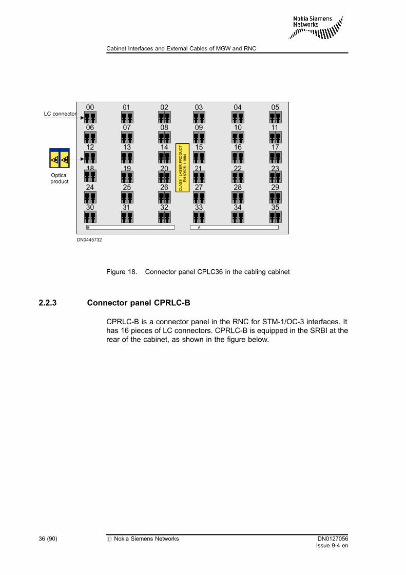
Figure 18. Connector panel CPLC36 in the cabling cabinet
2.2.3 Connector panel CPRLC-B
CPRLC-B is a connector panel in the RNC for STM-1/OC-3 interfaces. Ithas 16 pieces of LC connectors. CPRLC-B is equipped in the SRBI at therear of the cabinet, as shown in the figure below.
06 07 08 09 10 11
12 13 14 15 16 17
18 19 20 21 22 23
24 25 26 27 28 29
30 31 32 33 34 35
00 01 02 03 0504
CLASS1LASERPRODUCT
EN60825-1
1994
DN0445732
Opticalproduct
LC connector
36 (90) # Nokia Siemens Networks DN0127056Issue 9-4 en
Cabinet Interfaces and External Cables of MGW and RNC
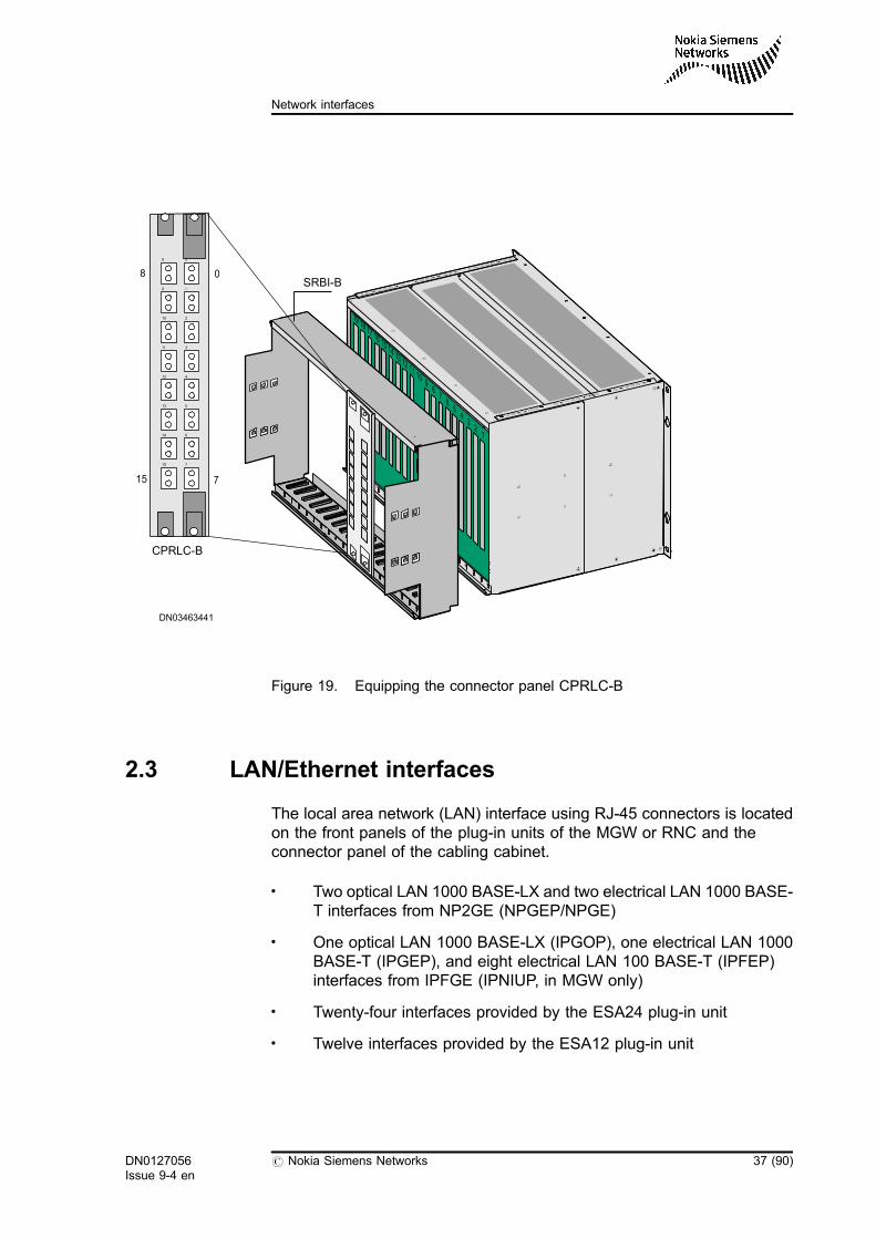
Figure 19. Equipping the connector panel CPRLC-B
2.3 LAN/Ethernet interfaces
The local area network (LAN) interface using RJ-45 connectors is locatedon the front panels of the plug-in units of the MGW or RNC and theconnector panel of the cabling cabinet.
. Two optical LAN 1000 BASE-LX and two electrical LAN 1000 BASE-T interfaces from NP2GE (NPGEP/NPGE)
. One optical LAN 1000 BASE-LX (IPGOP), one electrical LAN 1000BASE-T (IPGEP), and eight electrical LAN 100 BASE-T (IPFEP)interfaces from IPFGE (IPNIUP, in MGW only)
. Twenty-four interfaces provided by the ESA24 plug-in unit
. Twelve interfaces provided by the ESA12 plug-in unit
SRBI-B
--
8 0
9 1
10 2
11 3
12 4
13 5
14 6
15 7
CPRLC-B
DN03463441
08
715
DN0127056Issue 9-4 en
# Nokia Siemens Networks 37 (90)
Network interfaces
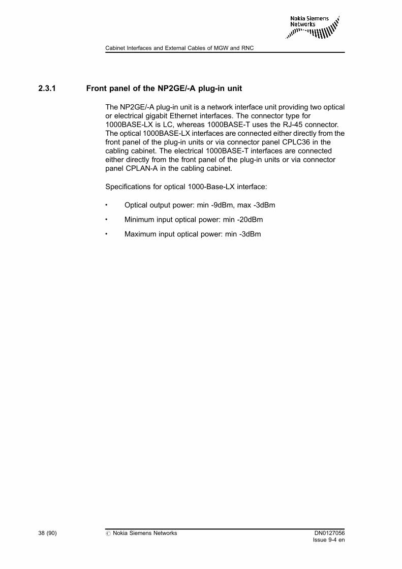
2.3.1 Front panel of the NP2GE/-A plug-in unit
The NP2GE/-A plug-in unit is a network interface unit providing two opticalor electrical gigabit Ethernet interfaces. The connector type for1000BASE-LX is LC, whereas 1000BASE-T uses the RJ-45 connector.The optical 1000BASE-LX interfaces are connected either directly from thefront panel of the plug-in units or via connector panel CPLC36 in thecabling cabinet. The electrical 1000BASE-T interfaces are connectedeither directly from the front panel of the plug-in units or via connectorpanel CPLAN-A in the cabling cabinet.
Specifications for optical 1000-Base-LX interface:
. Optical output power: min -9dBm, max -3dBm
. Minimum input optical power: min -20dBm
. Maximum input optical power: min -3dBm
38 (90) # Nokia Siemens Networks DN0127056Issue 9-4 en
Cabinet Interfaces and External Cables of MGW and RNC
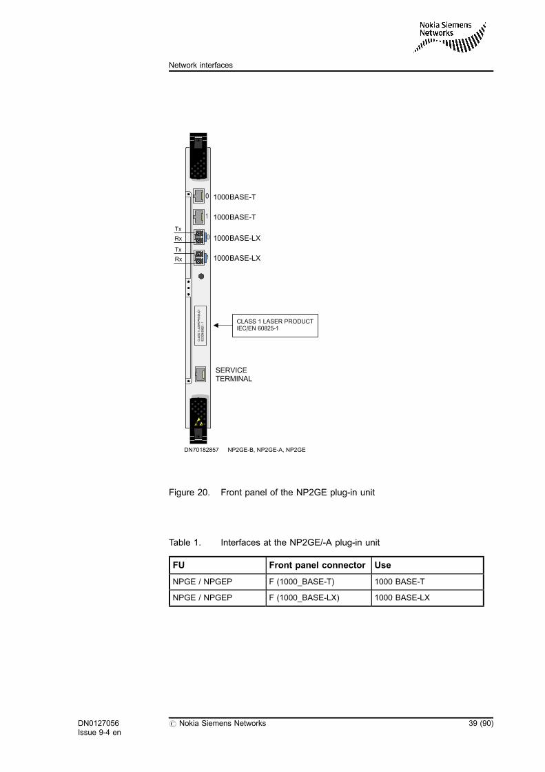
Figure 20. Front panel of the NP2GE plug-in unit
Table 1. Interfaces at the NP2GE/-A plug-in unit
FU Front panel connector Use
NPGE / NPGEP F (1000_BASE-T) 1000 BASE-T
NPGE / NPGEP F (1000_BASE-LX) 1000 BASE-LX
DN70182857 NP2GE-B, NP2GE-A, NP2GE
0
1
SERVICETERMINAL
CLASS 1 LASER PRODUCTIEC/EN 60825-1
1000BASE-T
1000BASE-LX
1000BASE-T
1000BASE-LX0
1
Tx
Rx
Tx
Rx
DN0127056Issue 9-4 en
# Nokia Siemens Networks 39 (90)
Network interfaces
2.3.2 Front panel of the IPFGE plug-in unit
The IPFGE plug-in unit is a network interface unit providing eight electricalFast Ethernet (100 Mbps) interfaces, one optical and one electrical gigabitEthernet. Only one of the gigabit interfaces can be used at a time (8 x fastEthernet, 1 x gigabit optical, or 1 x gigabit electrical). The connector typefor 1000BASE-LX is LC, whereas 1000BASE-T uses the RJ-45 connector.
Specifications for optical 1000-Base-LX interface:
. Optical output power: min -9dBm, max -3dBm
. Minimum input optical power: min -20dBm
. Maximum input optical power: min -3dBm
40 (90) # Nokia Siemens Networks DN0127056Issue 9-4 en
Cabinet Interfaces and External Cables of MGW and RNC
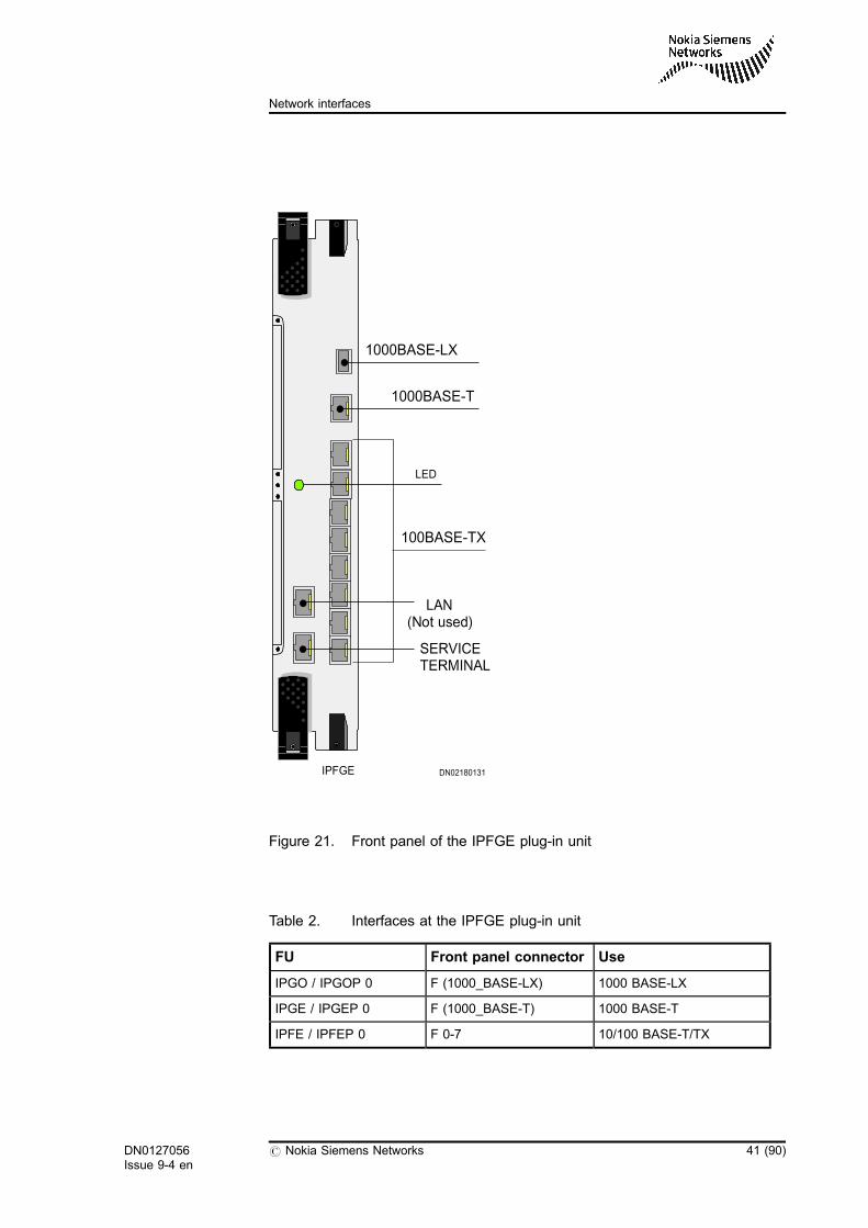
Figure 21. Front panel of the IPFGE plug-in unit
Table 2. Interfaces at the IPFGE plug-in unit
FU Front panel connector Use
IPGO / IPGOP 0 F (1000_BASE-LX) 1000 BASE-LX
IPGE / IPGEP 0 F (1000_BASE-T) 1000 BASE-T
IPFE / IPFEP 0 F 0-7 10/100 BASE-T/TX
IPFGE
LAN(Not used)
100BASE-TX
1000BASE-T
LED
1000BASE-LX
DN02180131
SERVICETERMINAL
DN0127056Issue 9-4 en
# Nokia Siemens Networks 41 (90)
Network interfaces
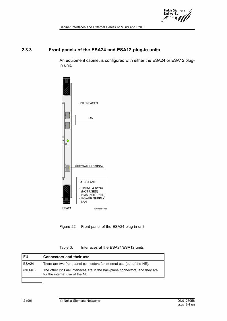
2.3.3 Front panels of the ESA24 and ESA12 plug-in units
An equipment cabinet is configured with either the ESA24 or ESA12 plug-in unit.
Figure 22. Front panel of the ESA24 plug-in unit
Table 3. Interfaces at the ESA24/ESA12 units
FU Connectors and their use
ESA24
(NEMU)
There are two front panel connectors for external use (out of the NE).
The other 22 LAN interfaces are in the backplane connectors, and they arefor the internal use of the NE.
ESA24 DN03451956
INTERFACES:
LAN
BACKPLANE:
- HMS (NOT USED)- POWER SUPPLY- LAN
SERVICE TERMINAL
- TIMING & SYNC(NOT USED)
42 (90) # Nokia Siemens Networks DN0127056Issue 9-4 en
Cabinet Interfaces and External Cables of MGW and RNC
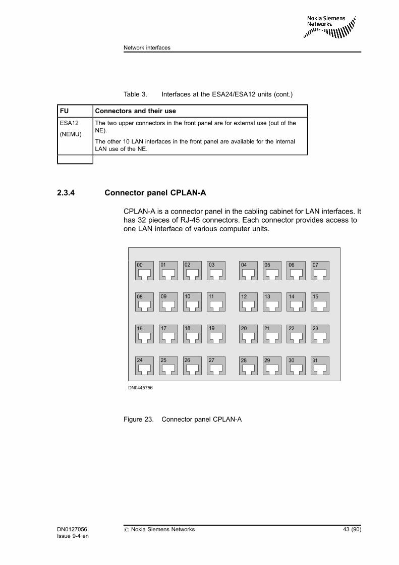
Table 3. Interfaces at the ESA24/ESA12 units (cont.)
FU Connectors and their use
ESA12
(NEMU)
The two upper connectors in the front panel are for external use (out of theNE).
The other 10 LAN interfaces in the front panel are available for the internalLAN use of the NE.
2.3.4 Connector panel CPLAN-A
CPLAN-A is a connector panel in the cabling cabinet for LAN interfaces. Ithas 32 pieces of RJ-45 connectors. Each connector provides access toone LAN interface of various computer units.
Figure 23. Connector panel CPLAN-A
00
08
16
24
01
09
17
02
10
18
03
11
19
04
12
20
05
13
21
06
14
22
07
15
23
25 26 27 28 29 30 31
DN0445756
DN0127056Issue 9-4 en
# Nokia Siemens Networks 43 (90)
Network interfaces

44 (90) # Nokia Siemens Networks DN0127056Issue 9-4 en
Cabinet Interfaces and External Cables of MGW and RNC
3 Maintenance interfaces
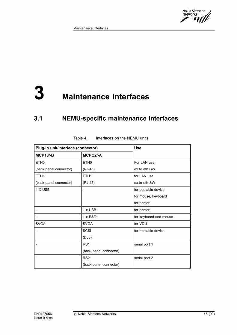
3.1 NEMU-specific maintenance interfaces
Table 4. Interfaces on the NEMU units
Plug-in unit/interface (connector) Use
MCP18/-B MCPC2/-A
ETH0
(back panel connector)
ETH0
(RJ-45)
For LAN use
ex to eth SW
ETH1
(back panel connector)
ETH1
(RJ-45)
for LAN use
ex to eth SW
4 X USB - for bootable device
for mouse, keyboard
for printer
- 1 x USB for printer
- 1 x PS/2 for keyboard and mouse
SVGA SVGA for VDU
- SCSI
(D68)
for bootable device
- RS1
(back panel connector)
serial port 1
- RS2
(back panel connector)
serial port 2
DN0127056Issue 9-4 en
# Nokia Siemens Networks 45 (90)
Maintenance interfaces
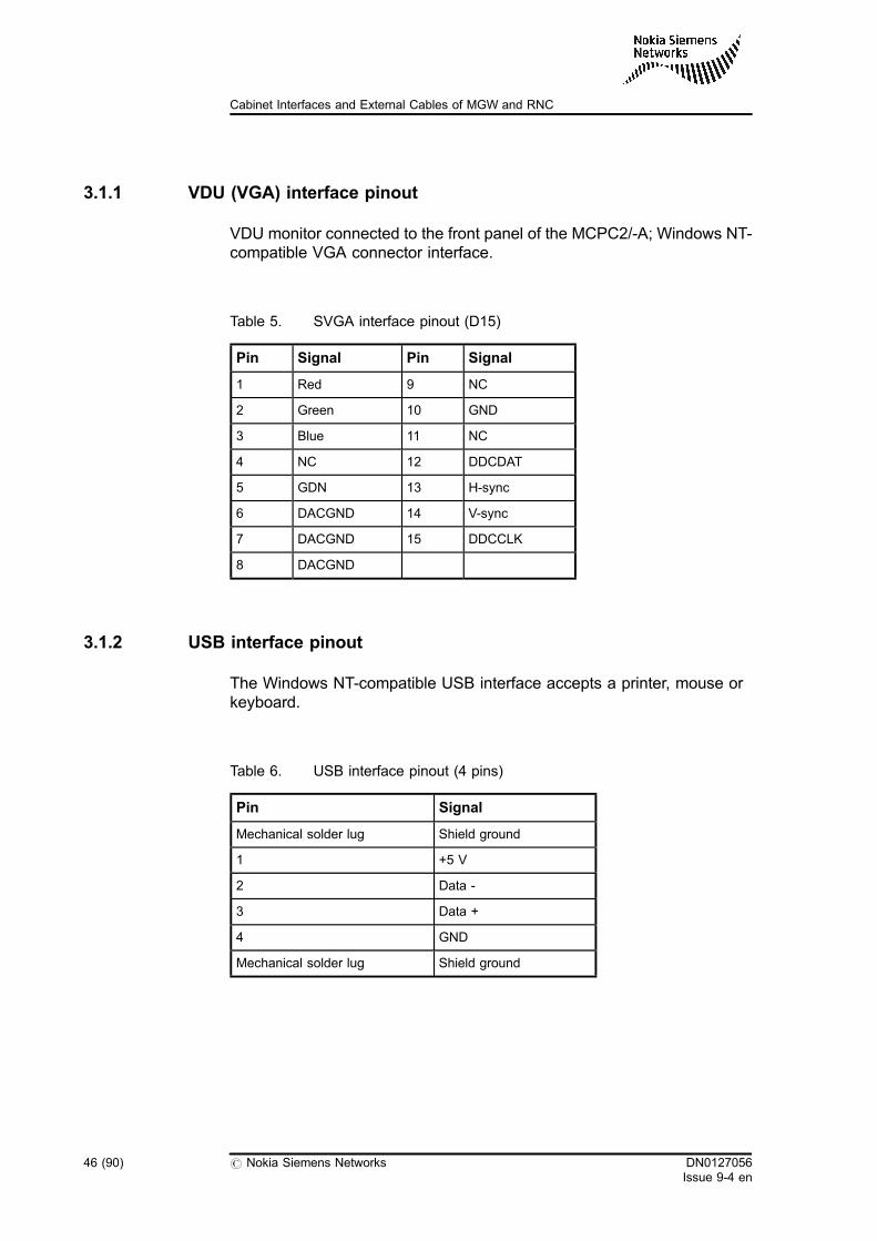
3.1.1 VDU (VGA) interface pinout
VDU monitor connected to the front panel of the MCPC2/-A; Windows NT-compatible VGA connector interface.
Table 5. SVGA interface pinout (D15)
Pin Signal Pin Signal
1 Red 9 NC
2 Green 10 GND
3 Blue 11 NC
4 NC 12 DDCDAT
5 GDN 13 H-sync
6 DACGND 14 V-sync
7 DACGND 15 DDCCLK
8 DACGND
3.1.2 USB interface pinout
The Windows NT-compatible USB interface accepts a printer, mouse orkeyboard.
Table 6. USB interface pinout (4 pins)
Pin Signal
Mechanical solder lug Shield ground
1 +5 V
2 Data -
3 Data +
4 GND
Mechanical solder lug Shield ground
46 (90) # Nokia Siemens Networks DN0127056Issue 9-4 en
Cabinet Interfaces and External Cables of MGW and RNC
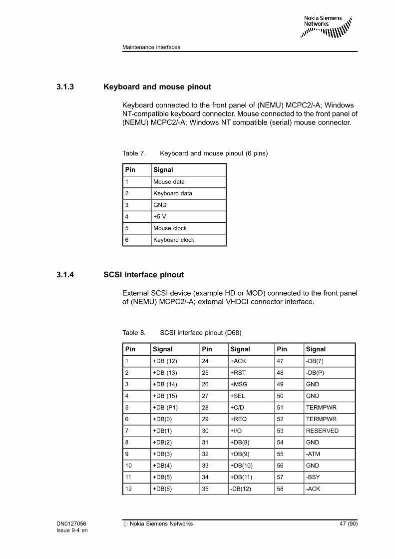
3.1.3 Keyboard and mouse pinout
Keyboard connected to the front panel of (NEMU) MCPC2/-A; WindowsNT-compatible keyboard connector. Mouse connected to the front panel of(NEMU) MCPC2/-A; Windows NT compatible (serial) mouse connector.
Table 7. Keyboard and mouse pinout (6 pins)
Pin Signal
1 Mouse data
2 Keyboard data
3 GND
4 +5 V
5 Mouse clock
6 Keyboard clock
3.1.4 SCSI interface pinout
External SCSI device (example HD or MOD) connected to the front panelof (NEMU) MCPC2/-A; external VHDCI connector interface.
Table 8. SCSI interface pinout (D68)
Pin Signal Pin Signal Pin Signal
1 +DB (12) 24 +ACK 47 -DB(7)
2 +DB (13) 25 +RST 48 -DB(P)
3 +DB (14) 26 +MSG 49 GND
4 +DB (15) 27 +SEL 50 GND
5 +DB (P1) 28 +C/D 51 TERMPWR
6 +DB(0) 29 +REQ 52 TERMPWR
7 +DB(1) 30 +I/O 53 RESERVED
8 +DB(2) 31 +DB(8) 54 GND
9 +DB(3) 32 +DB(9) 55 -ATM
10 +DB(4) 33 +DB(10) 56 GND
11 +DB(5) 34 +DB(11) 57 -BSY
12 +DB(6) 35 -DB(12) 58 -ACK
DN0127056Issue 9-4 en
# Nokia Siemens Networks 47 (90)
Maintenance interfaces
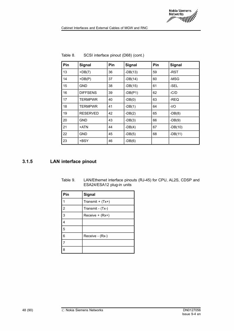
Table 8. SCSI interface pinout (D68) (cont.)
Pin Signal Pin Signal Pin Signal
13 +DB(7) 36 -DB(13) 59 -RST
14 +DB(P) 37 -DB(14) 60 -MSG
15 GND 38 -DB(15) 61 -SEL
16 DIFFSENS 39 -DB(P1) 62 -C/D
17 TERMPWR 40 -DB(0) 63 -REQ
18 TERMPWR 41 -DB(1) 64 -I/O
19 RESERVED 42 -DB(2) 65 -DB(8)
20 GND 43 -DB(3) 66 -DB(9)
21 +ATN 44 -DB(4) 67 -DB(10)
22 GND 45 -DB(5) 68 -DB(11)
23 +BSY 46 -DB(6)
3.1.5 LAN interface pinout
Table 9. LAN/Ethernet interface pinouts (RJ-45) for CPU, AL2S, CDSP andESA24/ESA12 plug-in units
Pin Signal
1 Transmit + (Tx+)
2 Transmit - (Tx-)
3 Receive + (Rx+)
4
5
6 Receive - (Rx-)
7
8
48 (90) # Nokia Siemens Networks DN0127056Issue 9-4 en
Cabinet Interfaces and External Cables of MGW and RNC
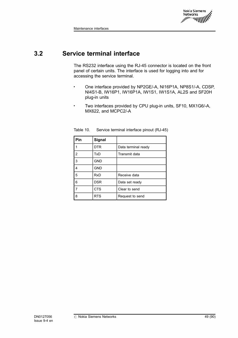
3.2 Service terminal interface
The RS232 interface using the RJ-45 connector is located on the frontpanel of certain units. The interface is used for logging into and foraccessing the service terminal.
. One interface provided by NP2GE/-A, NI16P1A, NP8S1/-A, CDSP,NI4S1-B, IW16P1, IW16P1A, IW1S1, IW1S1A, AL2S and SF20Hplug-in units
. Two interfaces provided by CPU plug-in units, SF10, MX1G6/-A,MX622, and MCPC2/-A
Table 10. Service terminal interface pinout (RJ-45)
Pin Signal
1 DTR Data terminal ready
2 TxD Transmit data
3 GND
4 GND
5 RxD Receive data
6 DSR Data set ready
7 CTS Clear to send
8 RTS Request to send
DN0127056Issue 9-4 en
# Nokia Siemens Networks 49 (90)
Maintenance interfaces
50 (90) # Nokia Siemens Networks DN0127056Issue 9-4 en
Cabinet Interfaces and External Cables of MGW and RNC
4 Connector panels for external alarm andsynchronisation interfaces
Depending on the equipment installed, the external alarm andsynchronisation interfaces are provided by different types of connectorpanels:
. CPAL-A and CPAL are for external alarm signals and for the externalalarm unit, EXAU/-A
. CPSY-A, CPSY-B and CPSY are for synchronisation
. CPSAL/-B is for both alarms and synchronisation
CPAL-A, CPSY-A, CPSY-B and CPSAL/-B are back panels of theequipment cabinet.
CPAL and CPSY are equipped in the cabling cabinet.
4.1 CPAL/-A and CPSAL/-B for alarm interfaces
Connector panels CPAL/-A and CPSAL/-B for alarms have one D25connector for EXAU/-A control, one D37 connector for general current orvoltage outputs, two D37 connectors for voltage-controlled inputs, and oneD25 connector for current-controlled alarm inputs.
DN0127056Issue 9-4 en
# Nokia Siemens Networks 51 (90)
Connector panels for external alarm and synchronisation interfaces
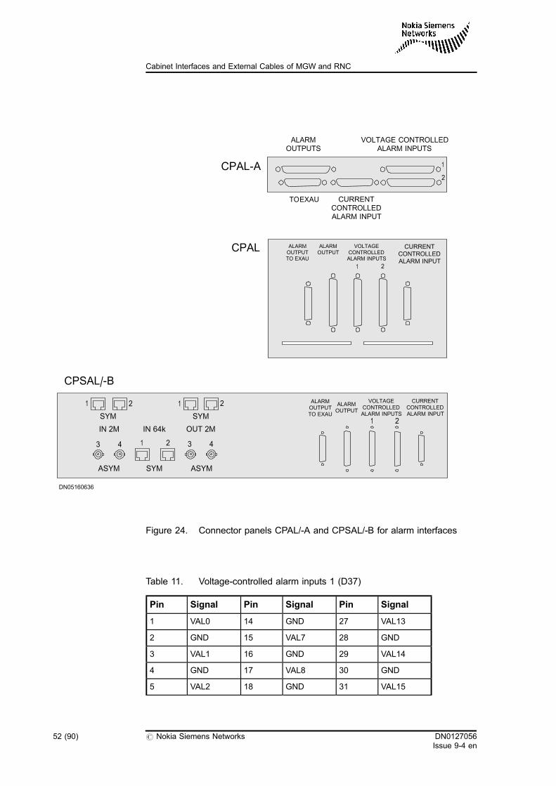
Figure 24. Connector panels CPAL/-A and CPSAL/-B for alarm interfaces
Table 11. Voltage-controlled alarm inputs 1 (D37)
Pin Signal Pin Signal Pin Signal
1 VAL0 14 GND 27 VAL13
2 GND 15 VAL7 28 GND
3 VAL1 16 GND 29 VAL14
4 GND 17 VAL8 30 GND
5 VAL2 18 GND 31 VAL15
CPAL ALARMOUTPUTTO EXAU
ALARMOUTPUT
VOLTAGECONTROLLEDALARM INPUTS
CURRENTCONTROLLEDALARM INPUT
1 2
DN05160636
1 2 1 2
1 23 4 3 4
SYM SYM
ASYM ASYMSYM
IN 2M OUT 2MIN 64k
ALARMOUTPUTTO EXAU
ALARMOUTPUT
VOLTAGECONTROLLEDALARM INPUTS
CURRENTCONTROLLEDALARM INPUT
21
CPSAL/-B
CPAL-A
TOEXAU
ALARMOUTPUTS
CURRENTCONTROLLEDALARM INPUT
VOLTAGE CONTROLLEDALARM INPUTS
1
2
52 (90) # Nokia Siemens Networks DN0127056Issue 9-4 en
Cabinet Interfaces and External Cables of MGW and RNC
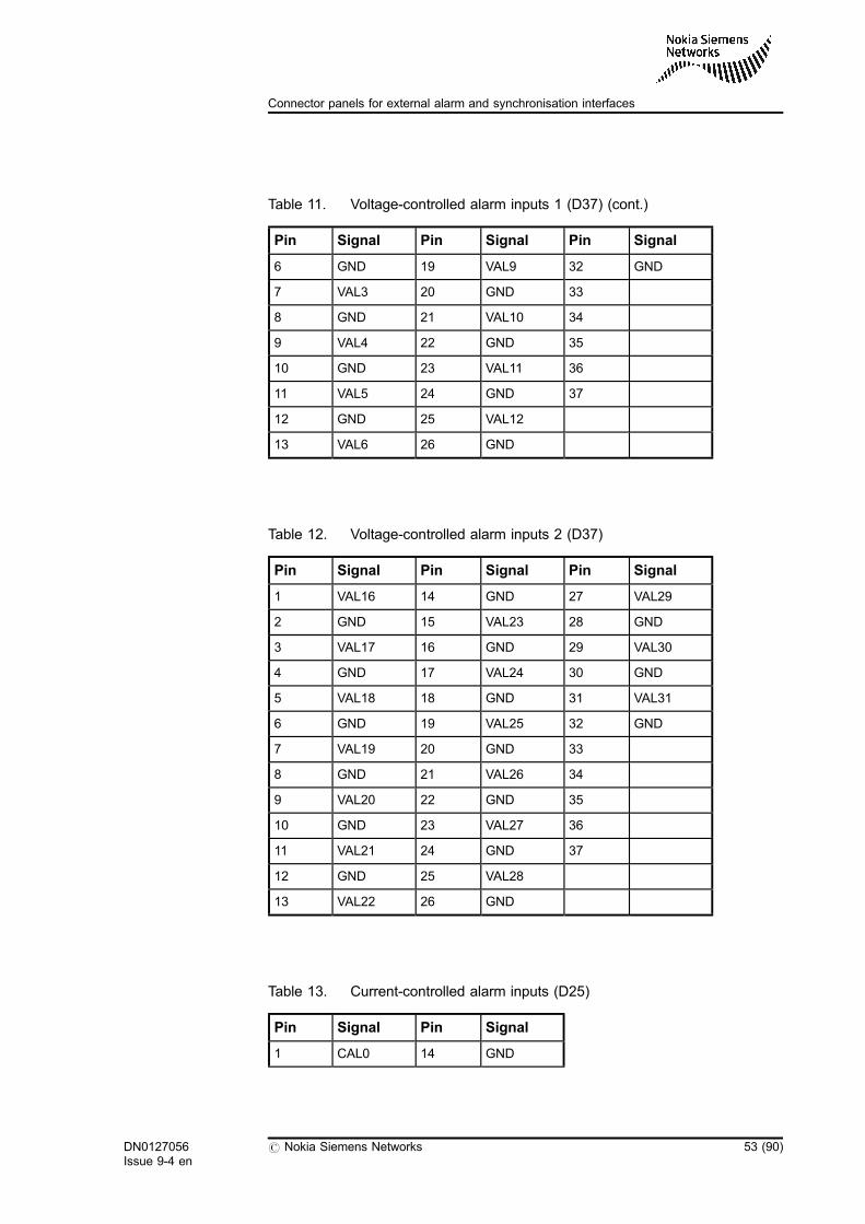
Table 11. Voltage-controlled alarm inputs 1 (D37) (cont.)
Pin Signal Pin Signal Pin Signal
6 GND 19 VAL9 32 GND
7 VAL3 20 GND 33
8 GND 21 VAL10 34
9 VAL4 22 GND 35
10 GND 23 VAL11 36
11 VAL5 24 GND 37
12 GND 25 VAL12
13 VAL6 26 GND
Table 12. Voltage-controlled alarm inputs 2 (D37)
Pin Signal Pin Signal Pin Signal
1 VAL16 14 GND 27 VAL29
2 GND 15 VAL23 28 GND
3 VAL17 16 GND 29 VAL30
4 GND 17 VAL24 30 GND
5 VAL18 18 GND 31 VAL31
6 GND 19 VAL25 32 GND
7 VAL19 20 GND 33
8 GND 21 VAL26 34
9 VAL20 22 GND 35
10 GND 23 VAL27 36
11 VAL21 24 GND 37
12 GND 25 VAL28
13 VAL22 26 GND
Table 13. Current-controlled alarm inputs (D25)
Pin Signal Pin Signal
1 CAL0 14 GND
DN0127056Issue 9-4 en
# Nokia Siemens Networks 53 (90)
Connector panels for external alarm and synchronisation interfaces
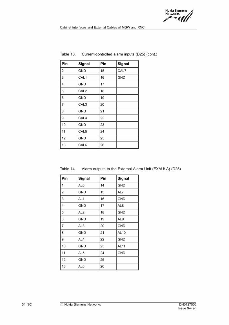
Table 13. Current-controlled alarm inputs (D25) (cont.)
Pin Signal Pin Signal
2 GND 15 CAL7
3 CAL1 16 GND
4 GND 17
5 CAL2 18
6 GND 19
7 CAL3 20
8 GND 21
9 CAL4 22
10 GND 23
11 CAL5 24
12 GND 25
13 CAL6 26
Table 14. Alarm outputs to the External Alarm Unit (EXAU/-A) (D25)
Pin Signal Pin Signal
1 AL0 14 GND
2 GND 15 AL7
3 AL1 16 GND
4 GND 17 AL8
5 AL2 18 GND
6 GND 19 AL9
7 AL3 20 GND
8 GND 21 AL10
9 AL4 22 GND
10 GND 23 AL11
11 AL5 24 GND
12 GND 25
13 AL6 26
54 (90) # Nokia Siemens Networks DN0127056Issue 9-4 en
Cabinet Interfaces and External Cables of MGW and RNC
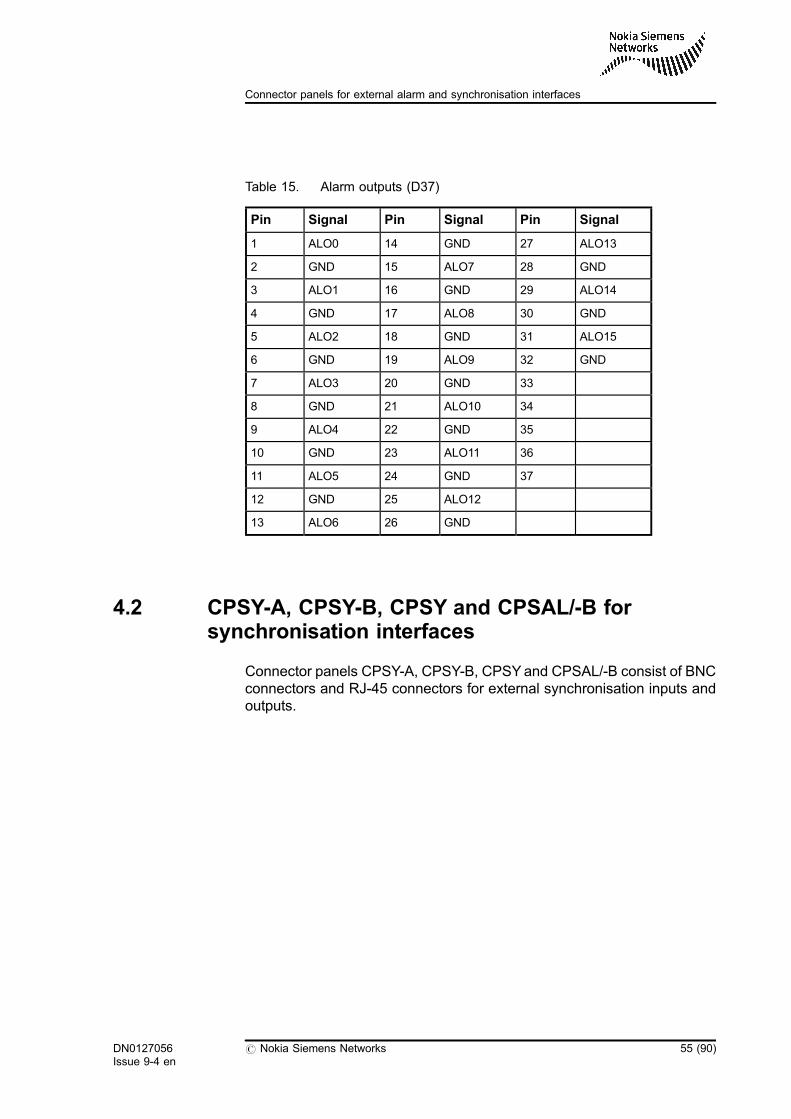
Table 15. Alarm outputs (D37)
Pin Signal Pin Signal Pin Signal
1 ALO0 14 GND 27 ALO13
2 GND 15 ALO7 28 GND
3 ALO1 16 GND 29 ALO14
4 GND 17 ALO8 30 GND
5 ALO2 18 GND 31 ALO15
6 GND 19 ALO9 32 GND
7 ALO3 20 GND 33
8 GND 21 ALO10 34
9 ALO4 22 GND 35
10 GND 23 ALO11 36
11 ALO5 24 GND 37
12 GND 25 ALO12
13 ALO6 26 GND
4.2 CPSY-A, CPSY-B, CPSY and CPSAL/-B forsynchronisation interfaces
Connector panels CPSY-A, CPSY-B, CPSYand CPSAL/-B consist of BNCconnectors and RJ-45 connectors for external synchronisation inputs andoutputs.
DN0127056Issue 9-4 en
# Nokia Siemens Networks 55 (90)
Connector panels for external alarm and synchronisation interfaces
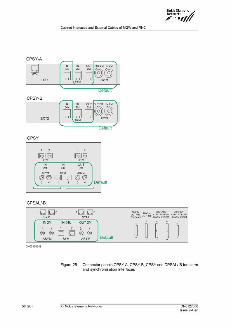
Figure 25. Connector panels CPSY-A, CPSY-B, CPSY and CPSAL/-B for alarmand synchronisation interfaces
DN05160648
CPSY-B
IN64k
IN2M
OUT2M
OUT 2M IN 2M
SYMASYMEXT2
Default
CPSY
1 2 1 2
SYM SYM
3 4 1 2 3 4
SYM ASYMASYM
2M 64k 2MIN IN OUT
Default
1 2 1 2
1 23 4 3 4
SYM SYM
ASYM ASYMSYM
IN 2M OUT 2MIN 64k
ALARMOUTPUTTO EXAU
ALARMOUTPUT
VOLTAGECONTROLLEDALARM INPUTS
CURRENTCONTROLLEDALARM INPUT
21
CPSAL/-B
Default
CPSY-A
IN64k
IN2M
OUT2M
OUT 2M IN 2M
SYMASYMEXT1
ETH
Default
56 (90) # Nokia Siemens Networks DN0127056Issue 9-4 en
Cabinet Interfaces and External Cables of MGW and RNC

Table 16. External synchronisation inputs and outputs
In Out Note
BNC BNC Default
BNC RJ-45 Optional
RJ-45 BNC Optional
RJ-45 RJ-45 Optional
It is possible to receive the line timing synchronisation from the externaloutput connectors on the synchronisation connector panel. Alternatively, ifthe line timing available in the network interface units is not used, the inputconnectors on the panel are also suitable for this purpose.
For cabling instructions, see Cable Lists for RNC and Cable Lists forMGW.
4.2.1 External inputs and outputs
IN 64K/IN 2M synchronisation interfaces
. Coaxial BNC connectors (unbalanced)
Two BNC connectors IN 2M provide two unbalanced inputinterfaces.
. RJ-45 connectors (balanced)
Two RJ-45 connectors provide balanced input interfaces for 2Msignals IN 2M, whereas two RJ-45 connectors provide balancedinput interfaces for 64K signals IN 64K.
Table 17. Synchronisation interface pinout (RJ-45)
Pin Signal
1 64K/2M IN A / Receive + (Rx+)
2 64K/2M IN B / Receive - (Rx-)
3–8 No signal
DN0127056Issue 9-4 en
# Nokia Siemens Networks 57 (90)
Connector panels for external alarm and synchronisation interfaces
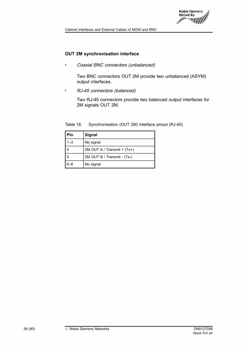
OUT 2M synchronisation interface
. Coaxial BNC connectors (unbalanced)
Two BNC connectors OUT 2M provide two unbalanced (ASYM)output interfaces.
. RJ-45 connectors (balanced)
Two RJ-45 connectors provide two balanced output interfaces for2M signals OUT 2M.
Table 18. Synchronisation (OUT 2M) interface pinout (RJ-45)
Pin Signal
1–3 No signal
4 2M OUT A / Transmit + (Tx+)
5 2M OUT B / Transmit - (Tx-)
6–8 No signal
58 (90) # Nokia Siemens Networks DN0127056Issue 9-4 en
Cabinet Interfaces and External Cables of MGW and RNC
5 Requirement specification for externalcables
5.1 E1 and T1 balanced (symmetrical) PCM
If the cabling cabinet is not used, E1 balanced (symmetrical) PCM cablesare connected to the BIE1T-A, BIE1T or E1T48-A interface panel, and ifthe cabling cabinet is used, the cables are connected to the CPETS-G,CPETS-E or CPETS interface panel.
Cable specifications
. Connector:. RJ-45 connector. Shielded construction. Gold plating on the contacts (0.76 µm). UL94 V-0 materials
. Cable:. Multi-cable (4 or more) bundled assembly. Nominal impedance: 120 ± 15 Ω for E1 and 100 ± 15 Ω for T1. E1 data transmission protocol specifies 6 dB as maximum
attenuation. AWG 26 or AWG 24 conductors. Continuous pair twisting. VW-1 materials. Flammability: IEC 332-1 or IEC 332-3. Operating temperature from 0° C to 70° C
DN0127056Issue 9-4 en
# Nokia Siemens Networks 59 (90)
Requirement specification for external cables
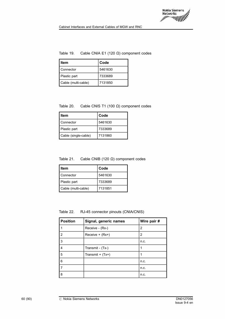
Table 19. Cable CNIA E1 (120 Ω) component codes
Item Code
Connector 5461630
Plastic part 7333689
Cable (multi-cable) 7131850
Table 20. Cable CNIS T1 (100 Ω) component codes
Item Code
Connector 5461630
Plastic part 7333689
Cable (single-cable) 7131860
Table 21. Cable CNIB (120 Ω) component codes
Item Code
Connector 5461630
Plastic part 7333689
Cable (multi-cable) 7131851
Table 22. RJ-45 connector pinouts (CNIA/CNIS)
Position Signal, generic names Wire pair #
1 Receive - (Rx-) 2
2 Receive + (Rx+) 2
3 n.c.
4 Transmit - (Tx-) 1
5 Transmit + (Tx+) 1
6 n.c.
7 n.c.
8 n.c.
60 (90) # Nokia Siemens Networks DN0127056Issue 9-4 en
Cabinet Interfaces and External Cables of MGW and RNC
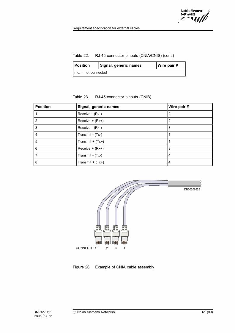
Table 22. RJ-45 connector pinouts (CNIA/CNIS) (cont.)
Position Signal, generic names Wire pair #
n.c. = not connected
Table 23. RJ-45 connector pinouts (CNIB)
Position Signal, generic names Wire pair #
1 Receive - (Rx-) 2
2 Receive + (Rx+) 2
3 Receive - (Rx-) 3
4 Transmit - (Tx-) 1
5 Transmit + (Tx+) 1
6 Receive + (Rx+) 3
7 Transmit - (Tx-) 4
8 Transmit + (Tx+) 4
Figure 26. Example of CNIA cable assembly
CONNECTOR
DN00206525
1 2 3 4
DN0127056Issue 9-4 en
# Nokia Siemens Networks 61 (90)
Requirement specification for external cables
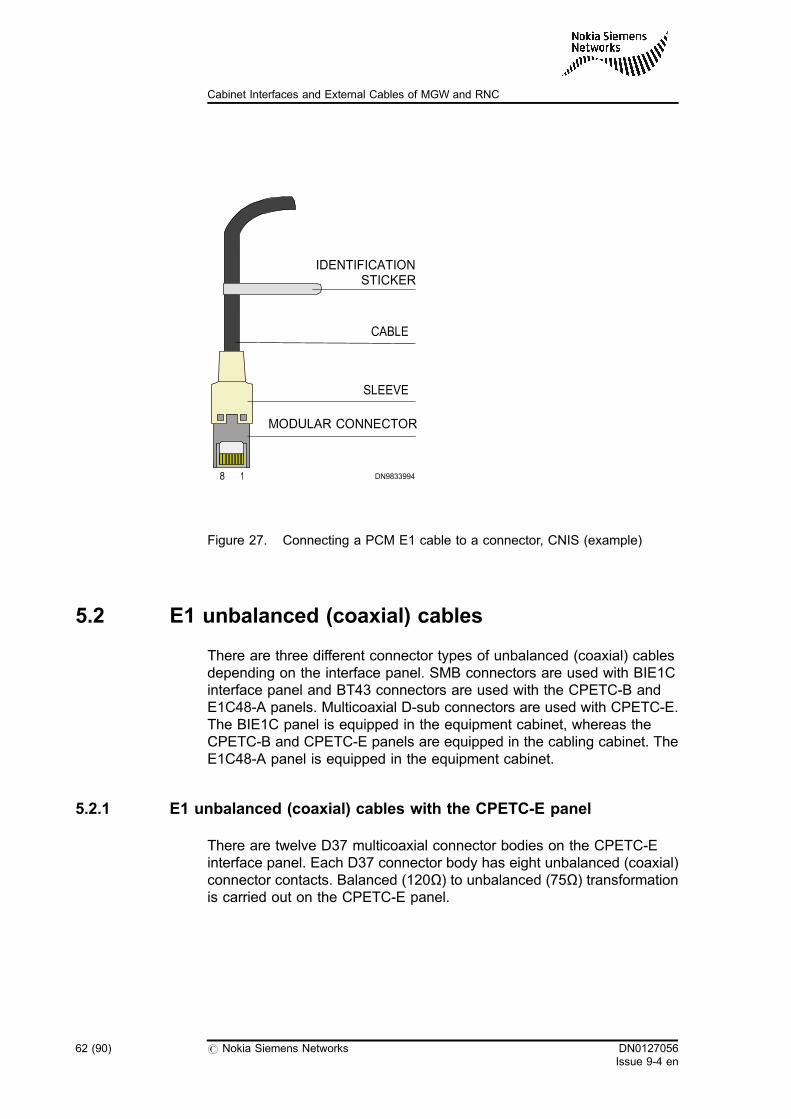
Figure 27. Connecting a PCM E1 cable to a connector, CNIS (example)
5.2 E1 unbalanced (coaxial) cables
There are three different connector types of unbalanced (coaxial) cablesdepending on the interface panel. SMB connectors are used with BIE1Cinterface panel and BT43 connectors are used with the CPETC-B andE1C48-A panels. Multicoaxial D-sub connectors are used with CPETC-E.The BIE1C panel is equipped in the equipment cabinet, whereas theCPETC-B and CPETC-E panels are equipped in the cabling cabinet. TheE1C48-A panel is equipped in the equipment cabinet.
5.2.1 E1 unbalanced (coaxial) cables with the CPETC-E panel
There are twelve D37 multicoaxial connector bodies on the CPETC-Einterface panel. Each D37 connector body has eight unbalanced (coaxial)connector contacts. Balanced (120Ω) to unbalanced (75Ω) transformationis carried out on the CPETC-E panel.
8
MODULAR CONNECTOR
SLEEVE
CABLE
IDENTIFICATIONSTICKER
DN98339941
62 (90) # Nokia Siemens Networks DN0127056Issue 9-4 en
Cabinet Interfaces and External Cables of MGW and RNC
Cable specifications
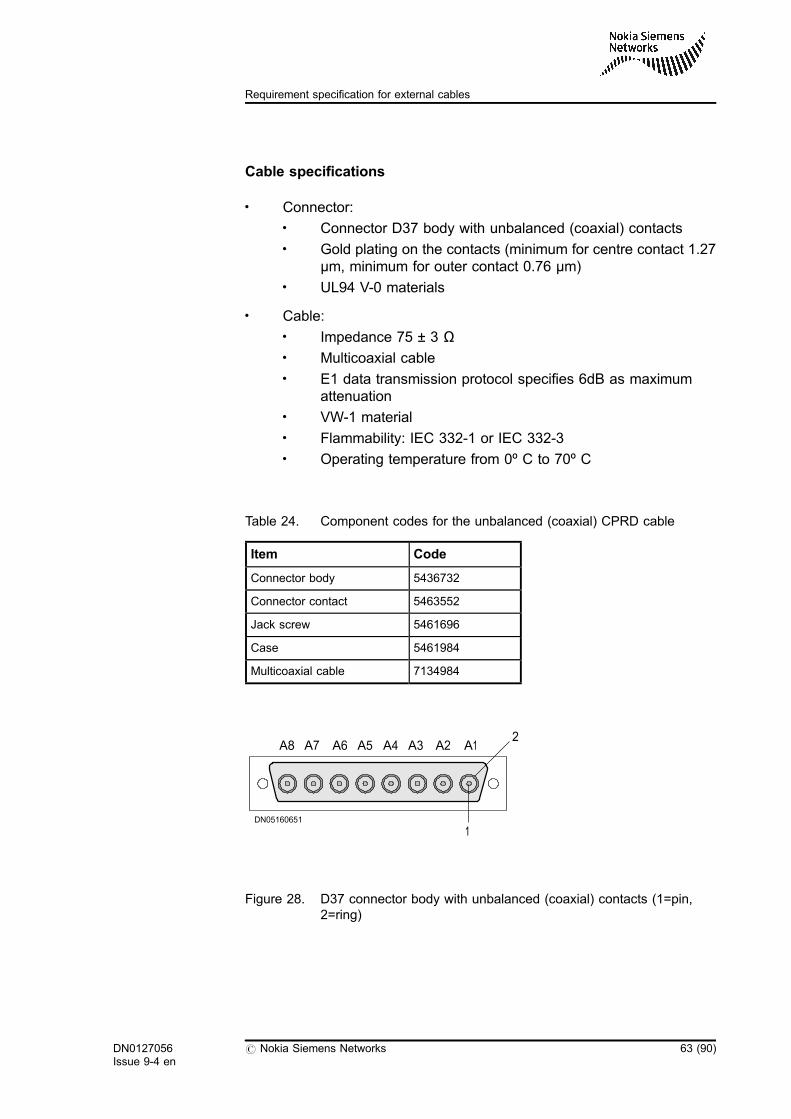
. Connector:. Connector D37 body with unbalanced (coaxial) contacts. Gold plating on the contacts (minimum for centre contact 1.27
µm, minimum for outer contact 0.76 µm). UL94 V-0 materials
. Cable:. Impedance 75 ± 3 Ω. Multicoaxial cable. E1 data transmission protocol specifies 6dB as maximum
attenuation. VW-1 material. Flammability: IEC 332-1 or IEC 332-3. Operating temperature from 0º C to 70º C
Table 24. Component codes for the unbalanced (coaxial) CPRD cable
Item Code
Connector body 5436732
Connector contact 5463552
Jack screw 5461696
Case 5461984
Multicoaxial cable 7134984
Figure 28. D37 connector body with unbalanced (coaxial) contacts (1=pin,2=ring)
A7A8 A5A6 A3A4 A1A2
DN05160651
1
2
DN0127056Issue 9-4 en
# Nokia Siemens Networks 63 (90)
Requirement specification for external cables
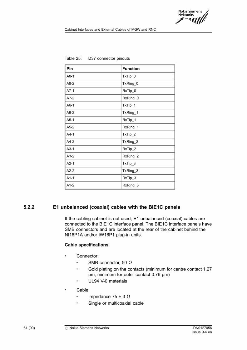
Table 25. D37 connector pinouts
Pin Function
A8-1 TxTip_0
A8-2 TxRing_0
A7-1 RxTip_0
A7-2 RxRing_0
A6-1 TxTip_1
A6-2 TxRing_1
A5-1 RxTip_1
A5-2 RxRing_1
A4-1 TxTip_2
A4-2 TxRing_2
A3-1 RxTip_2
A3-2 RxRing_2
A2-1 TxTip_3
A2-2 TxRing_3
A1-1 RxTip_3
A1-2 RxRing_3
5.2.2 E1 unbalanced (coaxial) cables with the BIE1C panels
If the cabling cabinet is not used, E1 unbalanced (coaxial) cables areconnected to the BIE1C interface panel. The BIE1C interface panels haveSMB connectors and are located at the rear of the cabinet behind theNI16P1A and/or IW16P1 plug-in units.
Cable specifications
. Connector:. SMB connector, 50 Ω. Gold plating on the contacts (minimum for centre contact 1.27
µm, minimum for outer contact 0.76 µm). UL94 V-0 materials
. Cable:. Impedance 75 ± 3 Ω. Single or multicoaxial cable
64 (90) # Nokia Siemens Networks DN0127056Issue 9-4 en
Cabinet Interfaces and External Cables of MGW and RNC
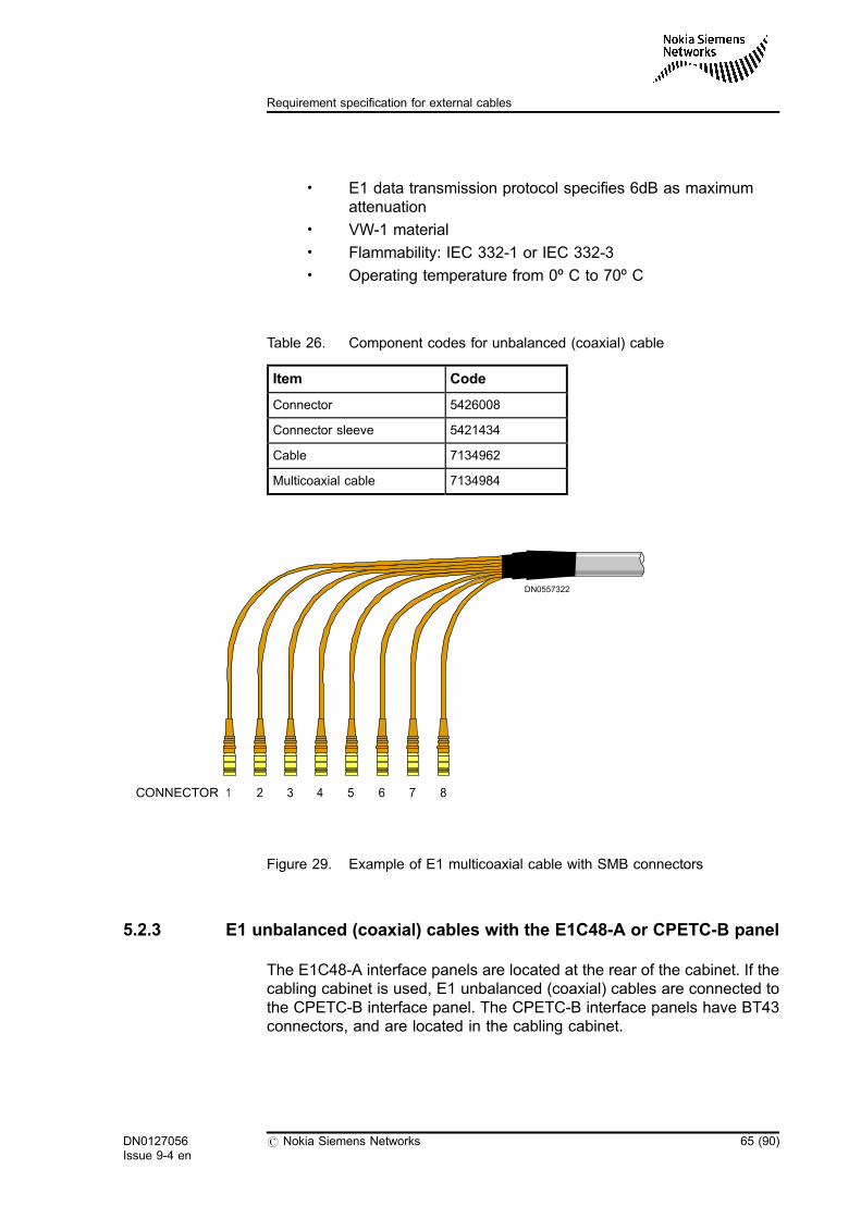
. E1 data transmission protocol specifies 6dB as maximumattenuation
. VW-1 material
. Flammability: IEC 332-1 or IEC 332-3
. Operating temperature from 0º C to 70º C
Table 26. Component codes for unbalanced (coaxial) cable
Item Code
Connector 5426008
Connector sleeve 5421434
Cable 7134962
Multicoaxial cable 7134984
Figure 29. Example of E1 multicoaxial cable with SMB connectors
5.2.3 E1 unbalanced (coaxial) cables with the E1C48-A or CPETC-B panel
The E1C48-A interface panels are located at the rear of the cabinet. If thecabling cabinet is used, E1 unbalanced (coaxial) cables are connected tothe CPETC-B interface panel. The CPETC-B interface panels have BT43connectors, and are located in the cabling cabinet.
CONNECTOR 1 2 3 4 5 6 7 8
DN0557322
DN0127056Issue 9-4 en
# Nokia Siemens Networks 65 (90)
Requirement specification for external cables
Cable specifications
. Connector:. BT43 connector, 75 Ω. Gold plating on the contacts (minimum for centre contact 1.27
µm, minimum for outer contact 0.76 µm). Recommended: UL94 V-0 materials
. Cable:. Impedance 75 ± 3 Ω. Single or multicoaxial cable. E1 data transmission protocol specifies 6dB as maximum
attenuation. VW-1 material. Flammability: IEC 332-1 or IEC 332-3. Operating temperature from 0° C to 70° C
Table 27. Component codes for unbalanced (coaxial) cable
Item Code
Connector 5425506
Connector sleeve 5421434
Cable 7134962
Multicoaxial cable 7134984
66 (90) # Nokia Siemens Networks DN0127056Issue 9-4 en
Cabinet Interfaces and External Cables of MGW and RNC
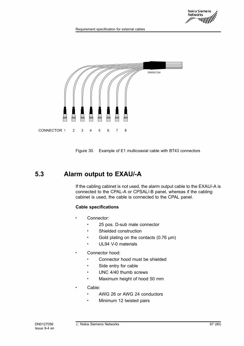
Figure 30. Example of E1 multicoaxial cable with BT43 connectors
5.3 Alarm output to EXAU/-A
If the cabling cabinet is not used, the alarm output cable to the EXAU/-A isconnected to the CPAL-A or CPSAL/-B panel, whereas if the cablingcabinet is used, the cable is connected to the CPAL panel.
Cable specifications
. Connector:. 25 pos. D-sub male connector. Shielded construction. Gold plating on the contacts (0.76 µm). UL94 V-0 materials
. Connector hood:. Connector hood must be shielded. Side entry for cable. UNC 4/40 thumb screws. Maximum height of hood 50 mm
. Cable:. AWG 26 or AWG 24 conductors. Minimum 12 twisted pairs
CONNECTOR 1 2 3 4 5 6 7 8
DN0557334
DN0127056Issue 9-4 en
# Nokia Siemens Networks 67 (90)
Requirement specification for external cables
. Shielded construction, screening effectiveness > 35dB at1GHz
. VW-1 materials
. Flammability: IEC 332-1 or IEC 332-3
. Operating temperature from 0° C to 70° C
Table 28. Cable CNDC (version A01) component codes
Item Code Note
Connector 5433649
Connector shell 5438878
Cable bushing 5438884
Cable 8 x 2 7131862 1)
1) Due to the 8 x 2 cable, only AL07 – AL7 alarm signals are connected.
Table 29. Cable CNDC (version A02) component codes
Item Code Note
Connector 5433649
Connector shell 5438878
Cable bushing 5438884
Cable 12 x 2 7131864 1)
1) Due to the 12 x 2 cable, alarm signal AL0 – AL11 are connected.Version A02 cable is needed when alarm signals AL6 – AL11 need to bechained. Only EXAU-A has the chaining feature.
The EXAU-A unit has an alarm output connector, allowing it to chain two ormore EXAU-A units so that alarms coming from the network element canbe displayed on two or more EXAU-A units.
The tables below describe the connector pinouts for the following cases:
68 (90) # Nokia Siemens Networks DN0127056Issue 9-4 en
Cabinet Interfaces and External Cables of MGW and RNC
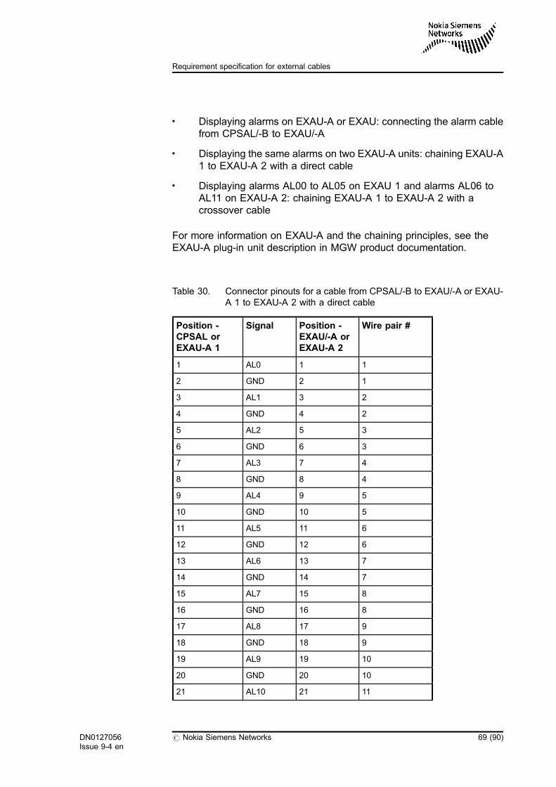
. Displaying alarms on EXAU-A or EXAU: connecting the alarm cablefrom CPSAL/-B to EXAU/-A
. Displaying the same alarms on two EXAU-A units: chaining EXAU-A1 to EXAU-A 2 with a direct cable
. Displaying alarms AL00 to AL05 on EXAU 1 and alarms AL06 toAL11 on EXAU-A 2: chaining EXAU-A 1 to EXAU-A 2 with acrossover cable
For more information on EXAU-A and the chaining principles, see theEXAU-A plug-in unit description in MGW product documentation.
Table 30. Connector pinouts for a cable from CPSAL/-B to EXAU/-A or EXAU-A 1 to EXAU-A 2 with a direct cable
Position -CPSAL orEXAU-A 1
Signal Position -EXAU/-A orEXAU-A 2
Wire pair #
1 AL0 1 1
2 GND 2 1
3 AL1 3 2
4 GND 4 2
5 AL2 5 3
6 GND 6 3
7 AL3 7 4
8 GND 8 4
9 AL4 9 5
10 GND 10 5
11 AL5 11 6
12 GND 12 6
13 AL6 13 7
14 GND 14 7
15 AL7 15 8
16 GND 16 8
17 AL8 17 9
18 GND 18 9
19 AL9 19 10
20 GND 20 10
21 AL10 21 11
DN0127056Issue 9-4 en
# Nokia Siemens Networks 69 (90)
Requirement specification for external cables
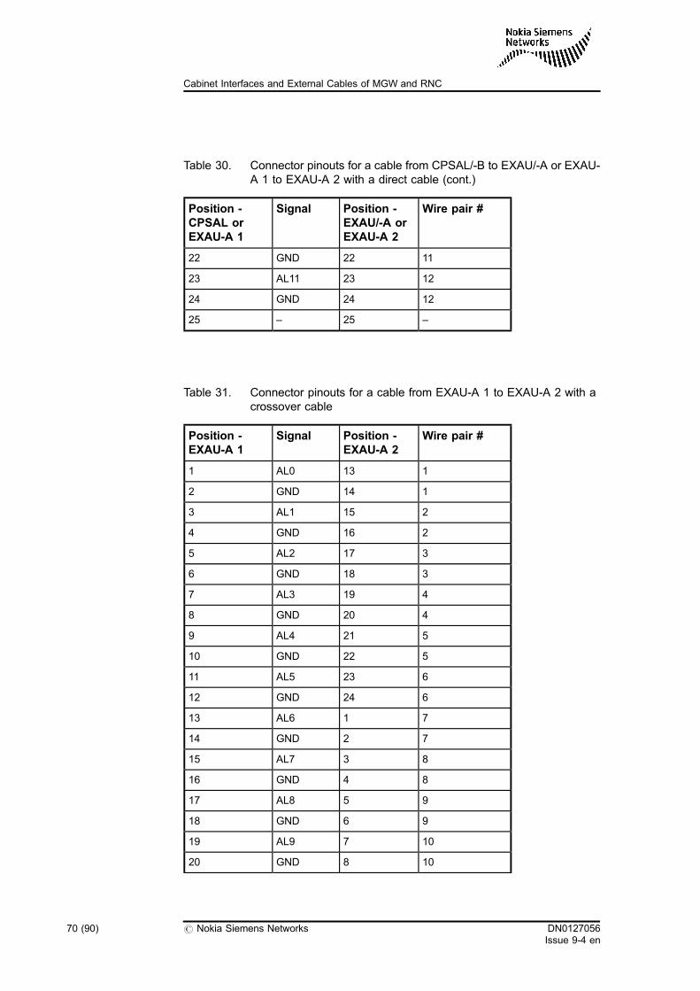
Table 30. Connector pinouts for a cable from CPSAL/-B to EXAU/-A or EXAU-A 1 to EXAU-A 2 with a direct cable (cont.)
Position -CPSAL orEXAU-A 1
Signal Position -EXAU/-A orEXAU-A 2
Wire pair #
22 GND 22 11
23 AL11 23 12
24 GND 24 12
25 – 25 –
Table 31. Connector pinouts for a cable from EXAU-A 1 to EXAU-A 2 with acrossover cable
Position -EXAU-A 1
Signal Position -EXAU-A 2
Wire pair #
1 AL0 13 1
2 GND 14 1
3 AL1 15 2
4 GND 16 2
5 AL2 17 3
6 GND 18 3
7 AL3 19 4
8 GND 20 4
9 AL4 21 5
10 GND 22 5
11 AL5 23 6
12 GND 24 6
13 AL6 1 7
14 GND 2 7
15 AL7 3 8
16 GND 4 8
17 AL8 5 9
18 GND 6 9
19 AL9 7 10
20 GND 8 10
70 (90) # Nokia Siemens Networks DN0127056Issue 9-4 en
Cabinet Interfaces and External Cables of MGW and RNC
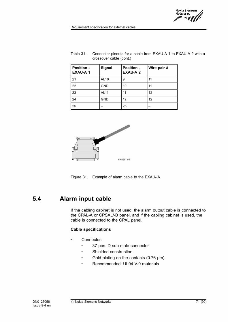
Table 31. Connector pinouts for a cable from EXAU-A 1 to EXAU-A 2 with acrossover cable (cont.)
Position -EXAU-A 1
Signal Position -EXAU-A 2
Wire pair #
21 AL10 9 11
22 GND 10 11
23 AL11 11 12
24 GND 12 12
25 – 25 –
Figure 31. Example of alarm cable to the EXAU/-A
5.4 Alarm input cable
If the cabling cabinet is not used, the alarm output cable is connected tothe CPAL-A or CPSAL/-B panel, and if the cabling cabinet is used, thecable is connected to the CPAL panel.
Cable specifications
. Connector:. 37 pos. D-sub male connector. Shielded construction. Gold plating on the contacts (0.76 µm). Recommended: UL94 V-0 materials
DN0557346
DN0127056Issue 9-4 en
# Nokia Siemens Networks 71 (90)
Requirement specification for external cables
. Connector hood:. Shielded construction. Side entry for cable. UNC 4/40 thumb screws. Maximum height of hood 55 mm (cable exits from side of
hood)
. Cable:. AWG 26 or AWG 24 conductors. Minimum 16 twisted pairs. Shielded construction, screening effectiveness > 35dB at
1GHz. VW-1 materials. Flammability: IEC 332-1 or IEC 332-3. Operating temperature from 0° C to 70º C
Table 32. Component codes for alarm output cable
Item Code
Connector 5437752
Connector shell 5461980
Strain relief 5434144
Cable 20 x 2 7131866
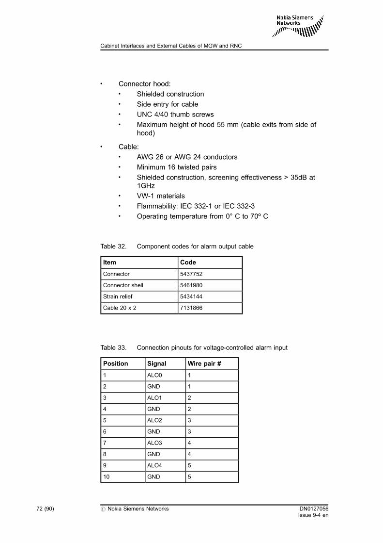
Table 33. Connection pinouts for voltage-controlled alarm input
Position Signal Wire pair #
1 ALO0 1
2 GND 1
3 ALO1 2
4 GND 2
5 ALO2 3
6 GND 3
7 ALO3 4
8 GND 4
9 ALO4 5
10 GND 5
72 (90) # Nokia Siemens Networks DN0127056Issue 9-4 en
Cabinet Interfaces and External Cables of MGW and RNC
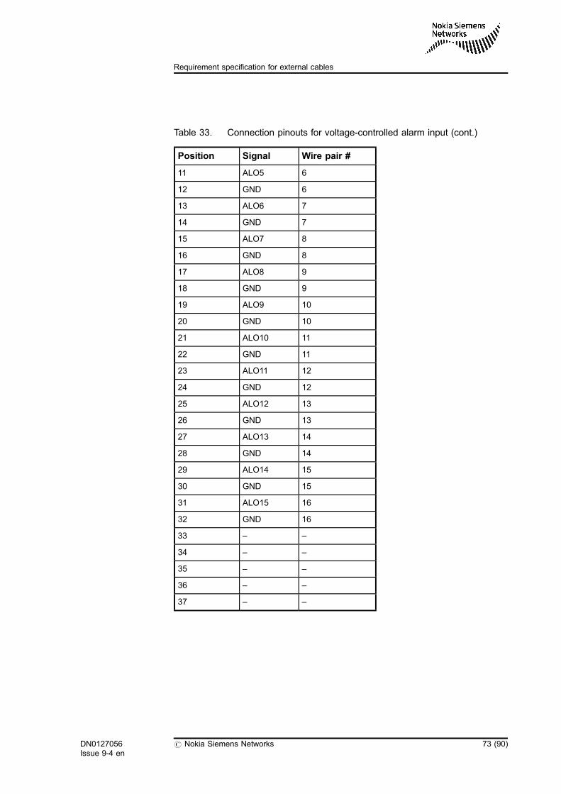
Table 33. Connection pinouts for voltage-controlled alarm input (cont.)
Position Signal Wire pair #
11 ALO5 6
12 GND 6
13 ALO6 7
14 GND 7
15 ALO7 8
16 GND 8
17 ALO8 9
18 GND 9
19 ALO9 10
20 GND 10
21 ALO10 11
22 GND 11
23 ALO11 12
24 GND 12
25 ALO12 13
26 GND 13
27 ALO13 14
28 GND 14
29 ALO14 15
30 GND 15
31 ALO15 16
32 GND 16
33 – –
34 – –
35 – –
36 – –
37 – –
DN0127056Issue 9-4 en
# Nokia Siemens Networks 73 (90)
Requirement specification for external cables
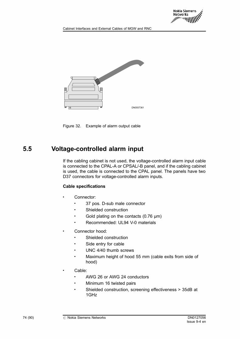
Figure 32. Example of alarm output cable
5.5 Voltage-controlled alarm input
If the cabling cabinet is not used, the voltage-controlled alarm input cableis connected to the CPAL-A or CPSAL/-B panel, and if the cabling cabinetis used, the cable is connected to the CPAL panel. The panels have twoD37 connectors for voltage-controlled alarm inputs.
Cable specifications
. Connector:. 37 pos. D-sub male connector. Shielded construction. Gold plating on the contacts (0.76 µm). Recommended: UL94 V-0 materials
. Connector hood:. Shielded construction. Side entry for cable. UNC 4/40 thumb screws. Maximum height of hood 55 mm (cable exits from side of
hood)
. Cable:. AWG 26 or AWG 24 conductors. Minimum 16 twisted pairs. Shielded construction, screening effectiveness > 35dB at
1GHz
DN0557361
74 (90) # Nokia Siemens Networks DN0127056Issue 9-4 en
Cabinet Interfaces and External Cables of MGW and RNC
. VW-1 materials
. Flammability: IEC 332-1 or IEC 332-3
. Operating temperature from 0° C to 70º C
Table 34. Component codes for voltage-controlled alarm input cable
Item Code
Connector 5437752
Connector shell 5461980
Strain relief 5434144
Cable 20x2 7131866
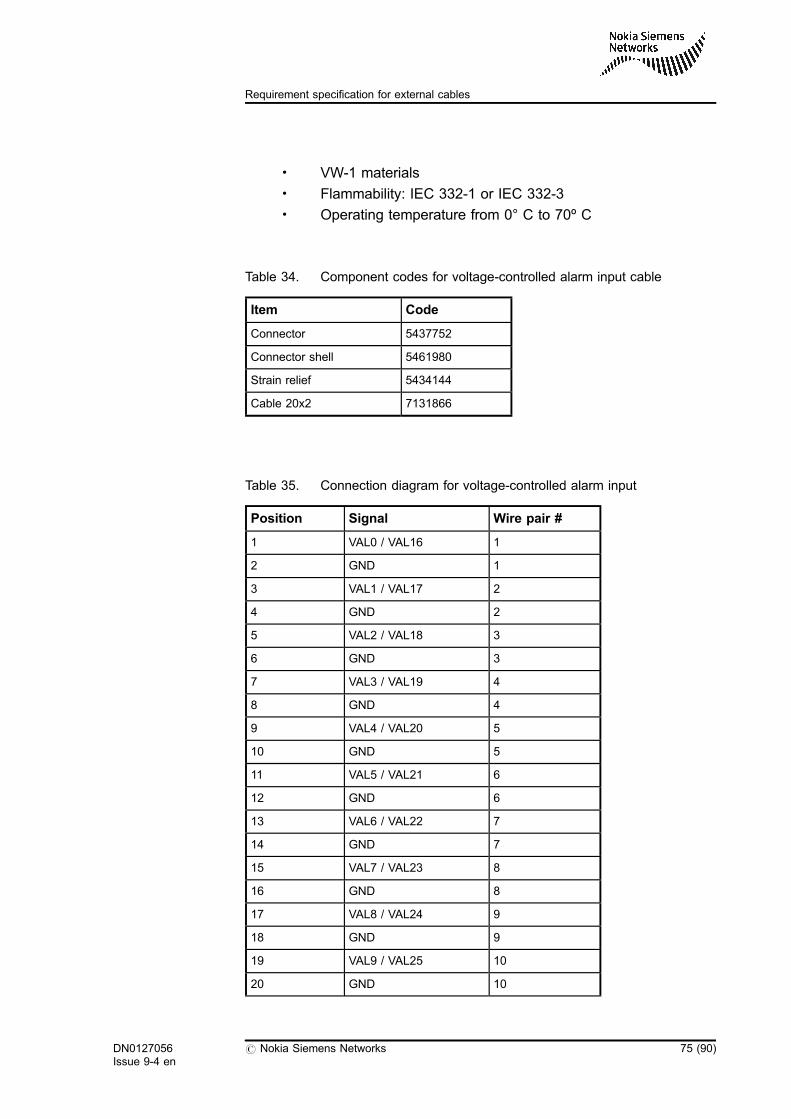
Table 35. Connection diagram for voltage-controlled alarm input
Position Signal Wire pair #
1 VAL0 / VAL16 1
2 GND 1
3 VAL1 / VAL17 2
4 GND 2
5 VAL2 / VAL18 3
6 GND 3
7 VAL3 / VAL19 4
8 GND 4
9 VAL4 / VAL20 5
10 GND 5
11 VAL5 / VAL21 6
12 GND 6
13 VAL6 / VAL22 7
14 GND 7
15 VAL7 / VAL23 8
16 GND 8
17 VAL8 / VAL24 9
18 GND 9
19 VAL9 / VAL25 10
20 GND 10
DN0127056Issue 9-4 en
# Nokia Siemens Networks 75 (90)
Requirement specification for external cables
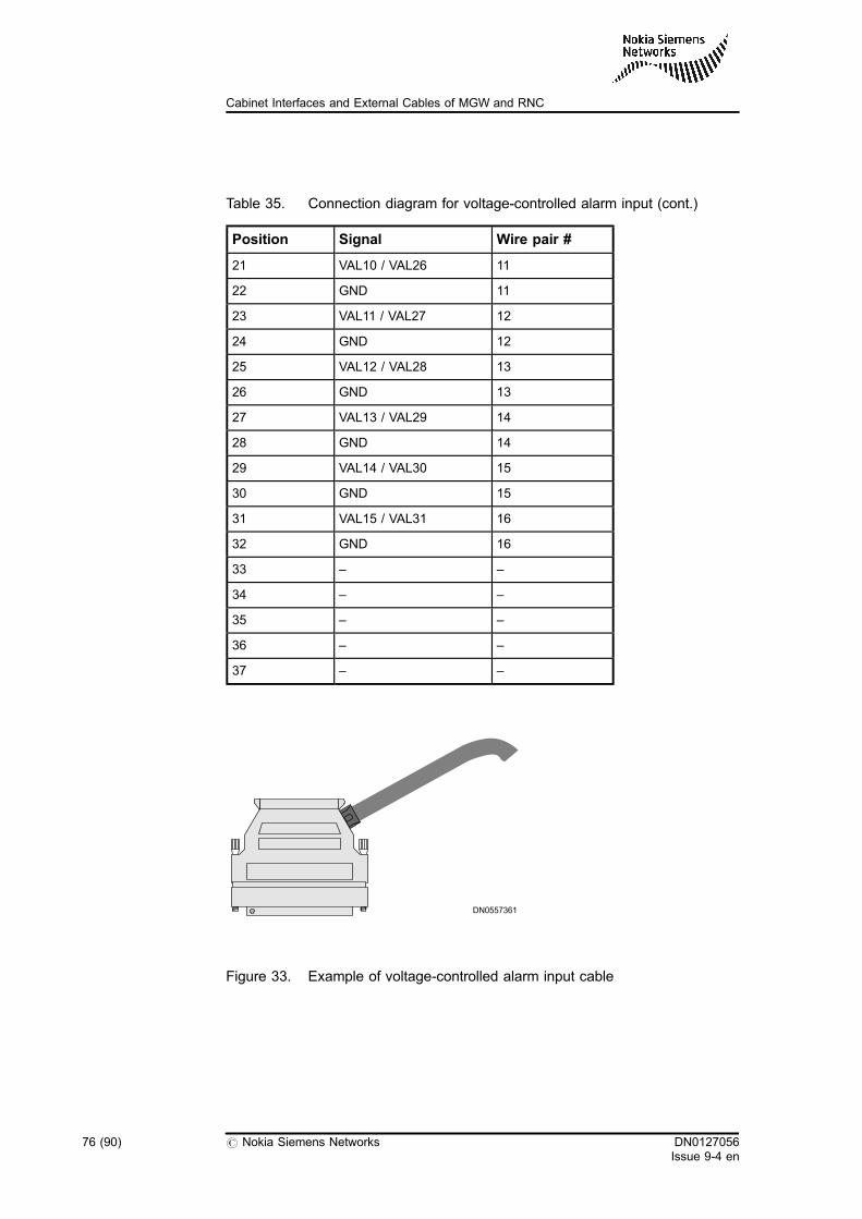
Table 35. Connection diagram for voltage-controlled alarm input (cont.)
Position Signal Wire pair #
21 VAL10 / VAL26 11
22 GND 11
23 VAL11 / VAL27 12
24 GND 12
25 VAL12 / VAL28 13
26 GND 13
27 VAL13 / VAL29 14
28 GND 14
29 VAL14 / VAL30 15
30 GND 15
31 VAL15 / VAL31 16
32 GND 16
33 – –
34 – –
35 – –
36 – –
37 – –
Figure 33. Example of voltage-controlled alarm input cable
DN0557361
76 (90) # Nokia Siemens Networks DN0127056Issue 9-4 en
Cabinet Interfaces and External Cables of MGW and RNC
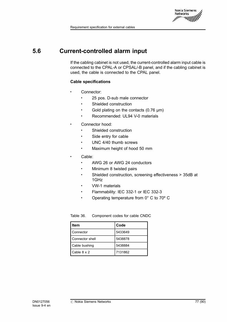
5.6 Current-controlled alarm input
If the cabling cabinet is not used, the current-controlled alarm input cable isconnected to the CPAL-A or CPSAL/-B panel, and if the cabling cabinet isused, the cable is connected to the CPAL panel.
Cable specifications
. Connector:. 25 pos. D-sub male connector. Shielded construction. Gold plating on the contacts (0.76 µm). Recommended: UL94 V-0 materials
. Connector hood:. Shielded construction. Side entry for cable. UNC 4/40 thumb screws. Maximum height of hood 50 mm
. Cable:. AWG 26 or AWG 24 conductors. Minimum 8 twisted pairs. Shielded construction, screening effectiveness > 35dB at
1GHz. VW-1 materials. Flammability: IEC 332-1 or IEC 332-3. Operating temperature from 0° C to 70º C
Table 36. Component codes for cable CNDC
Item Code
Connector 5433649
Connector shell 5438878
Cable bushing 5438884
Cable 8 x 2 7131862
DN0127056Issue 9-4 en
# Nokia Siemens Networks 77 (90)
Requirement specification for external cables
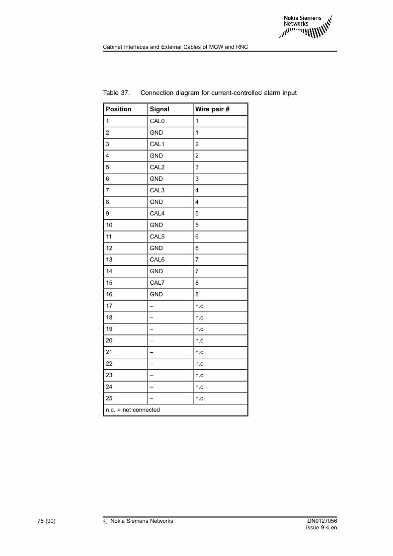
Table 37. Connection diagram for current-controlled alarm input
Position Signal Wire pair #
1 CAL0 1
2 GND 1
3 CAL1 2
4 GND 2
5 CAL2 3
6 GND 3
7 CAL3 4
8 GND 4
9 CAL4 5
10 GND 5
11 CAL5 6
12 GND 6
13 CAL6 7
14 GND 7
15 CAL7 8
16 GND 8
17 – n.c.
18 – n.c.
19 – n.c.
20 – n.c.
21 – n.c.
22 – n.c.
23 – n.c.
24 – n.c.
25 – n.c.
n.c. = not connected
78 (90) # Nokia Siemens Networks DN0127056Issue 9-4 en
Cabinet Interfaces and External Cables of MGW and RNC
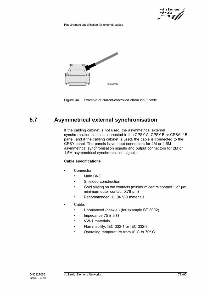
Figure 34. Example of current-controlled alarm input cable
5.7 Asymmetrical external synchronisation
If the cabling cabinet is not used, the asymmetrical externalsynchronisation cable is connected to the CPSY-A, CPSY-B or CPSAL/-Bpanel, and if the cabling cabinet is used, the cable is connected to theCPSY panel. The panels have input connectors for 2M or 1.5Masymmetrical synchronisation signals and output connectors for 2M or1.5M asymmetrical synchronisation signals.
Cable specifications
. Connector:. Male BNC. Shielded construction. Gold plating on the contacts (minimum centre contact 1.27 µm,
minimum outer contact 0.76 µm). Recommended: UL94 V-0 materials
. Cable:. Unbalanced (coaxial) (for example BT 3002). Impedance 75 ± 3 Ω. VW-1 materials. Flammability: IEC 332-1 or IEC 332-3. Operating temperature from 0° C to 70º C
DN0557346
DN0127056Issue 9-4 en
# Nokia Siemens Networks 79 (90)
Requirement specification for external cables
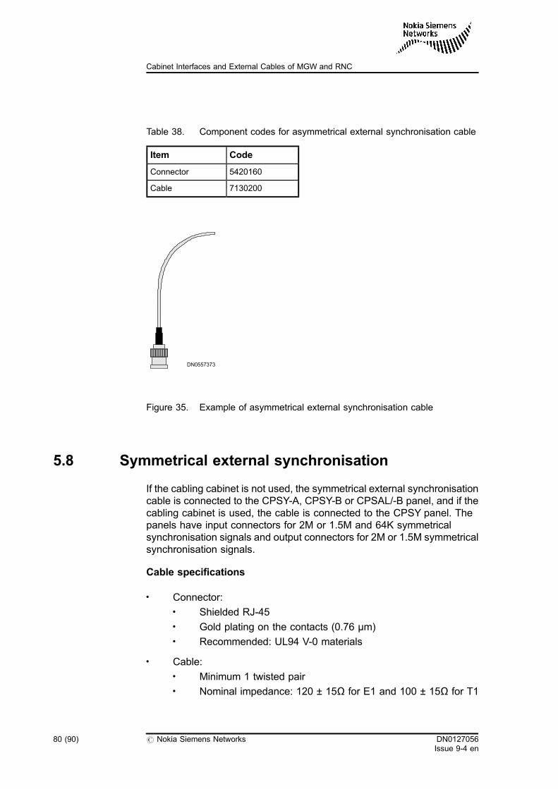
Table 38. Component codes for asymmetrical external synchronisation cable
Item Code
Connector 5420160
Cable 7130200
Figure 35. Example of asymmetrical external synchronisation cable
5.8 Symmetrical external synchronisation
If the cabling cabinet is not used, the symmetrical external synchronisationcable is connected to the CPSY-A, CPSY-B or CPSAL/-B panel, and if thecabling cabinet is used, the cable is connected to the CPSY panel. Thepanels have input connectors for 2M or 1.5M and 64K symmetricalsynchronisation signals and output connectors for 2M or 1.5M symmetricalsynchronisation signals.
Cable specifications
. Connector:. Shielded RJ-45. Gold plating on the contacts (0.76 µm). Recommended: UL94 V-0 materials
. Cable:. Minimum 1 twisted pair. Nominal impedance: 120 ± 15Ω for E1 and 100 ± 15Ω for T1
DN0557373
80 (90) # Nokia Siemens Networks DN0127056Issue 9-4 en
Cabinet Interfaces and External Cables of MGW and RNC
. E1 data transmission protocol specifies 6dB as maximumattenuation
. AWG 26 or AWG 24 solid conductors
. Continuous pair twisting
. VW-1 materials
. Flammability: IEC 332-1 or IEC 332-3
. Operating temperature from 0° C to 70º C
Table 39. Cable CNIA E1 component codes (120Ω, receive and transmitsignals connected)
Item Code
Connector 5461630
Plastic part 7333689
Cable 7131850
Table 40. 64K / 2M / 1.5M symmetrical synchronisation input connectorpinouts
Position Signal, generic names Wire pair #
1 64K/2M IN A / Receive + (Rx+) 1
2 64K/2M IN B / Receive - (Rx-) 1
3 n.c.
4 n.c.
5 n.c.
6 n.c.
7 n.c.
8 n.c.
n.c. = not connected
Table 41. 2M / 1.5M symmetrical synchronisation output connector pinouts
Position Signal, generic names Wire pair #
1 n.c.
2 n.c.
DN0127056Issue 9-4 en
# Nokia Siemens Networks 81 (90)
Requirement specification for external cables
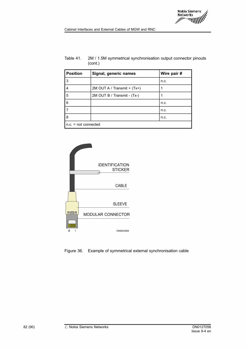
Table 41. 2M / 1.5M symmetrical synchronisation output connector pinouts(cont.)
Position Signal, generic names Wire pair #
3 n.c.
4 2M OUT A / Transmit + (Tx+) 1
5 2M OUT B / Transmit - (Tx-) 1
6 n.c.
7 n.c.
8 n.c.
n.c. = not connected
Figure 36. Example of symmetrical external synchronisation cable
8
MODULAR CONNECTOR
SLEEVE
CABLE
IDENTIFICATIONSTICKER
DN98339941
82 (90) # Nokia Siemens Networks DN0127056Issue 9-4 en
Cabinet Interfaces and External Cables of MGW and RNC
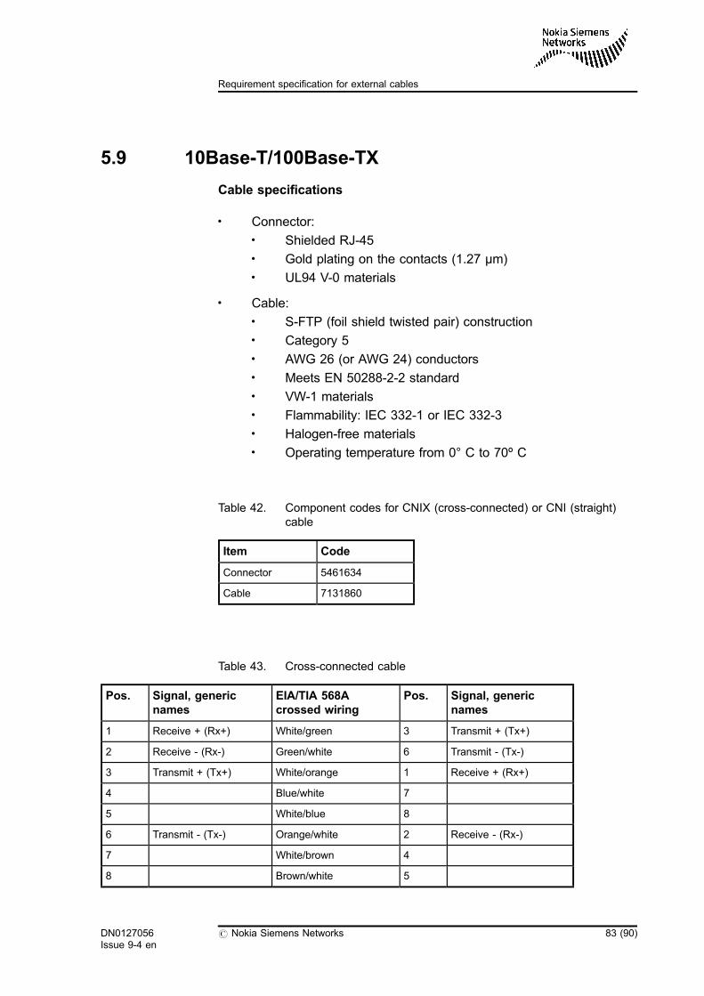
5.9 10Base-T/100Base-TX
Cable specifications
. Connector:. Shielded RJ-45. Gold plating on the contacts (1.27 µm). UL94 V-0 materials
. Cable:. S-FTP (foil shield twisted pair) construction. Category 5. AWG 26 (or AWG 24) conductors. Meets EN 50288-2-2 standard. VW-1 materials. Flammability: IEC 332-1 or IEC 332-3. Halogen-free materials. Operating temperature from 0° C to 70º C
Table 42. Component codes for CNIX (cross-connected) or CNI (straight)cable
Item Code
Connector 5461634
Cable 7131860
Table 43. Cross-connected cable
Pos. Signal, genericnames
EIA/TIA 568Acrossed wiring
Pos. Signal, genericnames
1 Receive + (Rx+) White/green 3 Transmit + (Tx+)
2 Receive - (Rx-) Green/white 6 Transmit - (Tx-)
3 Transmit + (Tx+) White/orange 1 Receive + (Rx+)
4 Blue/white 7
5 White/blue 8
6 Transmit - (Tx-) Orange/white 2 Receive - (Rx-)
7 White/brown 4
8 Brown/white 5
DN0127056Issue 9-4 en
# Nokia Siemens Networks 83 (90)
Requirement specification for external cables
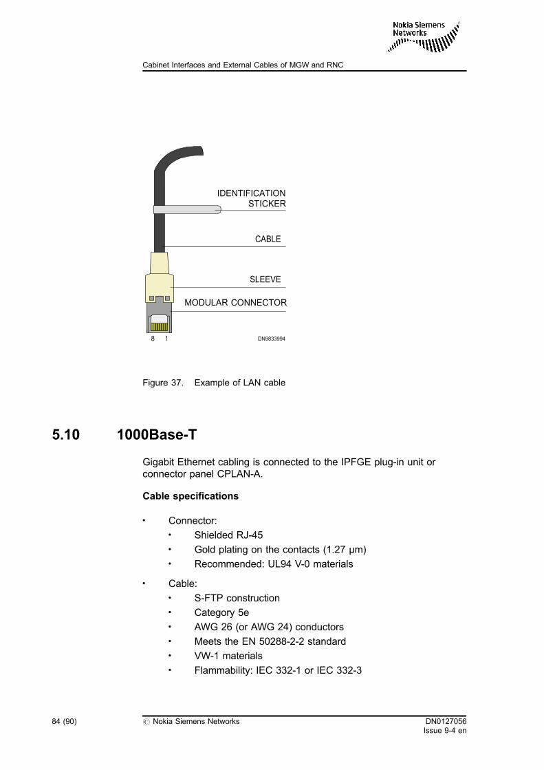
Figure 37. Example of LAN cable
5.10 1000Base-T
Gigabit Ethernet cabling is connected to the IPFGE plug-in unit orconnector panel CPLAN-A.
Cable specifications
. Connector:. Shielded RJ-45. Gold plating on the contacts (1.27 µm). Recommended: UL94 V-0 materials
. Cable:. S-FTP construction. Category 5e. AWG 26 (or AWG 24) conductors. Meets the EN 50288-2-2 standard. VW-1 materials. Flammability: IEC 332-1 or IEC 332-3
8
MODULAR CONNECTOR
SLEEVE
CABLE
IDENTIFICATIONSTICKER
DN98339941
84 (90) # Nokia Siemens Networks DN0127056Issue 9-4 en
Cabinet Interfaces and External Cables of MGW and RNC
. Halogen-free materials
. Operating temperature from 0° C to 70º C
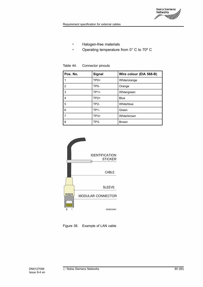
Table 44. Connector pinouts
Pos. No. Signal Wire colour (EIA 568-B)
1 TP0+ White/orange
2 TP0- Orange
3 TP1+ White/green
4 TP2+ Blue
5 TP2- White/blue
6 TP1- Green
7 TP3+ White/brown
8 TP3- Brown
Figure 38. Example of LAN cable
8
MODULAR CONNECTOR
SLEEVE
CABLE
IDENTIFICATIONSTICKER
DN98339941
DN0127056Issue 9-4 en
# Nokia Siemens Networks 85 (90)
Requirement specification for external cables
5.11 Optical STM-1
If the cabling cabinet is not used, optical STM-1 fiber is connected to theCPRLC-B panel (RNC), or directly to the front panel of the plug-in unit(MGW). If the cabling cabinet is used, the fiber is connected to theCPLC36 connector panel or to the front panel of the plug-in unit in theequipment cabinet.
Cable specifications
. Connector:. Duplex LC according to GR-326 and IEC 60874. Mating durability for 200 reconnects, insertion loss change <
0.2dB. Maximum insertion loss 0.3dB. SPC finish. Return loss > 45dB. Zirconia ferrule. Efficiency of strain relief > 80N. UL94V-0
. Boot:. 90° angle boot (minimum requirement at the MGW or RNC
connection end). Maximum installation height 70 mm. UL94V-0
. Cable:. 9/125 µm single mode fibre. Attenuation: ≤ 0,5 dB / Km at λ = 1310 nm and ≤ 0.4 dB / Km at
λ = 1550 nm. Cable must fulfill ITU-T G.652 for interface type STM-1 optical
(ITU-T G.957, table 1). Cable must fulfill ATM 155 Mb/s. Duplex type. UL VW-1 or UL94V-0. Fibre cables must be provided with a common secondary
overall jacket which will not slide along the cables. Maximum cable outer diameter 6.6 mm. Minimum bending radius during installation < 65 mm. Minimum bending radius in service < 43 mm (according to IEC
794-1-E11)
86 (90) # Nokia Siemens Networks DN0127056Issue 9-4 en
Cabinet Interfaces and External Cables of MGW and RNC
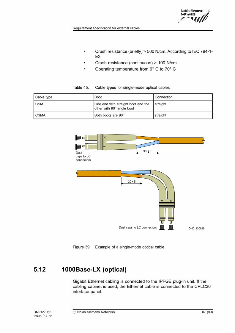
. Crush resistance (briefly) > 500 N/cm. According to IEC 794-1-E3
. Crush resistance (continuous) > 100 N/cm
. Operating temperature from 0° C to 70º C
Table 45. Cable types for single-mode optical cables
Cable type Boot Connection
CSM One end with straight boot and theother with 90º angle boot
straight
CSMA Both boots are 90º straight
Figure 39. Example of a single-mode optical cable
5.12 1000Base-LX (optical)
Gigabit Ethernet cabling is connected to the IPFGE plug-in unit. If thecabling cabinet is used, the Ethernet cable is connected to the CPLC36interface panel.
30 5
30 5
DN01130619Dust caps to LC connectors
Dustcaps to LCconnectors
B
B
DN0127056Issue 9-4 en
# Nokia Siemens Networks 87 (90)
Requirement specification for external cables
Cable specifications
. Connector. Duplex LC according to GR-326 and IEC 60874. Mating durability for 200 reconnects, insertion loss change <
0.2dB. Maximum insertion loss 0.3dB. SPC finish. Return loss > 45dB. Zirconia ferrule. Blue colour. Efficiency of strain relief > 80N. UL94V-0
. Boot. 90° angle boot. Maximum installation height 70 mm. UL94V-0
. Cable. 9/125 µm single mode fibre. Attenuation: ≤ 0,5 dB / Km at λ = 1310 nm and ≤ 0.4 dB / Km at
λ = 1550 nm. Cable must fulfill ITU-T G.652 for interface type STM-1 optical
(ITU-T G.957, table 1). Cable must fulfill ATM 155 Mb/s. Duplex type. UL VW-1 or UL94V-0. Fibre cables must be provided with a common secondary
overall jacket which will not slide along the cables. Maximum cable outer diameter 6.6 mm. Minimum bending radius during installation < 65 mm. Minimum bending radius in service < 43 mm (according to IEC
794-1-E11). Crush resistance (briefly) > 500 N/cm. According to IEC 794-1-
E3. Crush resistance (continuous) > 100 N/cm. Operating temperature from 0° C to 70º C
88 (90) # Nokia Siemens Networks DN0127056Issue 9-4 en
Cabinet Interfaces and External Cables of MGW and RNC
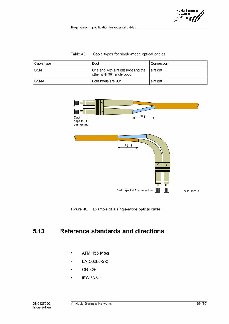
Table 46. Cable types for single-mode optical cables
Cable type Boot Connection
CSM One end with straight boot and theother with 90º angle boot
straight
CSMA Both boots are 90º straight
Figure 40. Example of a single-mode optical cable
5.13 Reference standards and directions
. ATM 155 Mb/s
. EN 50288-2-2
. GR-326
. IEC 332-1
30 5
30 5
DN01130619Dust caps to LC connectors
Dustcaps to LCconnectors
B
B
DN0127056Issue 9-4 en
# Nokia Siemens Networks 89 (90)
Requirement specification for external cables
. IEC 332-3
. IEC 754-1
. IEC 794-1
. IEC 874-1
. IEC 60874
. IEC 61754-20-4
. ITU-T G.652
. TIA/EIA-568
. UL94V-0
. UL VW-1
. GR253
90 (90) # Nokia Siemens Networks DN0127056Issue 9-4 en
Cabinet Interfaces and External Cables of MGW and RNC