Embed Size (px)
Citation preview
The electronic pdf version of this document, available free of chargefrom http://www.dnvgl.com, is the officially binding version.
DNV GL AS
SERVICE SPECIFICATION
DNVGL-SE-0479 Edition August 2017
Verification of process facilities
FOREWORD
DNV GL service specifications contain procedural requirements for obtaining and retainingcertificates and other conformity statements to the objects, personnel, organisations and/oroperations in question.
© DNV GL AS August 2017
Any comments may be sent by e-mail to [email protected]
This service document has been prepared based on available knowledge, technology and/or information at the time of issuance of thisdocument. The use of this document by others than DNV GL is at the user's sole risk. DNV GL does not accept any liability or responsibilityfor loss or damages resulting from any use of this document.

Cha
nges
- c
urre
nt
Service specification — DNVGL-SE-0479. Edition August 2017 Page 3Verification of process facilities
DNV GL AS
CHANGES – CURRENT
GeneralThis document supersedes the June 2004 edition of DNV-OSS-307.The purpose of the revision of this service document is to comply with the new DNV GL document reference code system and profile requirements following the merger between DNV and GL in 2013. Changes mainly consist of updated company name and references to other documents within the DNV GL portfolio.
Some references in this service document may refer to documents in the DNV GL portfolio not yet published (planned published within 2017). In such cases please see the relevant legacy DNV or GL document. References to external documents (non-DNV GL) have not been updated.
Editorial correctionsIn addition to the above stated changes, editorial corrections may have been made.
Con
tent
s
Service specification — DNVGL-SE-0479. Edition August 2017 Page 4Verification of process facilities
DNV GL AS
CONTENTS
Changes – current.................................................................................................. 3
Section 1 General....................................................................................................51.1 General............................................................................................. 51.2 Risk based verification..................................................................... 61.3 Defining a verification plan...............................................................71.4 DNV GL process facility statement of conformity..............................81.5 Definitions and abbreviations........................................................... 81.6 References...................................................................................... 11
Section 2 Service overview................................................................................... 122.1 General........................................................................................... 122.2 Service process...............................................................................122.3 Project initiation............................................................................. 142.4 Project realization.......................................................................... 142.5 Project operation............................................................................ 202.6 Verification documents................................................................... 21
Appendix A Selection of verification level.............................................................22A.1 General........................................................................................... 22A.2 Trigger questions............................................................................22
Appendix B Detailed example scope of work tables for verification...................... 25B.1 General........................................................................................... 25B.2 Description of terms used in the scope of work tables....................25B.3 Overall project management.......................................................... 26B.4 Design.............................................................................................27B.5 Construction..................................................................................33B.6 Operations.....................................................................................39
Appendix C Examples of verification documents...................................................40C.1 Verification documents................................................................... 40C.2 Use of quality management systems.............................................. 42C.3 Document forms............................................................................. 44
Changes – historic................................................................................................50

Service specification — DNVGL-SE-0479. Edition August 2017 Page 5Verification of process facilities
DNV GL AS
SECTION 1 GENERAL
1.1 General
1.1.1 Introduction
1.1.1.1 This DNV GL service specification gives criteria for and guidance on verification of the integrity andfunction of parts or phases of process facilities.
— It introduces a levelled description of verification involvement during all phases of an asset's life.— The document facilitates a categorisation into risk levels high, medium and low, assisting in an evaluation
of the risk level.— The document assists in planning the verification through the making of a verification plan, and describes
the DNV GL documentation of the process throughout.
1.1.1.2 This specification falls under the top level document DNVGL-SE-0474 Risk based verification.
1.1.1.3 The descriptions in this specification directly support a simplified verification planning as described inDNVGL-SE-0474. When using the advanced or combined planning, the descriptions will give good referencesand starting points.
Guidance note:The latest revision of all DNV GL documents may be found in the publications list in the DNV GL web site www.dnvgl.com.
---e-n-d---o-f---g-u-i-d-a-n-c-e---n-o-t-e---
1.1.2 Objectives
1.1.2.1 The objectives of this specification are to describe the following for a process facility:
— preparation of a verification plan using DNV GL’s risk differentiated levels of verification activities anddetailed example scope of work tables
— DNV GL’s implementation and reporting of the verification plan.
1.1.3 Scope of application for verification
1.1.3.1 This specification may be adopted for the verification of parts of process facilities or selected projectphases.
1.1.3.2 Process facilities typically comprise the following systems:
— process safety functions— pressure relieving devices— blowdown and flare system— HIPPS system— utility systems— piping— pressure vessels (not covered by this SE (service specification))— passive fire protection— active fire protection— HVAC systems— fire and gas detection systems— shutdown systems

Service specification — DNVGL-SE-0479. Edition August 2017 Page 6Verification of process facilities
DNV GL AS
— process equipment— hazardous area classification.
which are applied in various configurations and tailored to each particular project’s specific requirements.
1.1.3.3 This specification describes the principles of a levelled verification involvement. These principles maybe applied both for planning of any need or obligations for independent external verification (third party) aswell as internal company verification (second party).
1.1.4 Structure of this document— Section 1 explains the relationship between this document and DNV GL’s overall risk based verification
systematics.— Sec.2 describes the activities for each project and the project phases for a process facility.— App.A poses trigger questions to assist in the selection of verification level— App.B gives detailed example scope of work tables for the different phases and levels of involvement.
These tables are the basis for the development of project specific scope of work tables.— App.C gives example verification documents and describes the documents issued during and as a result of
the verification process. The use of quality management systems is addressed here also.
1.2 Risk based verification
1.2.1 Elements of the service
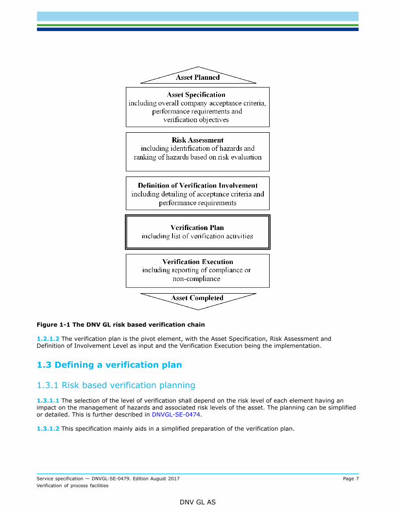
1.2.1.1 The risk based verification concept is described in DNVGL-SE-0474 and visualized by Figure 1-1.
Service specification — DNVGL-SE-0479. Edition August 2017 Page 7Verification of process facilities
DNV GL AS
Figure 1-1 The DNV GL risk based verification chain
1.2.1.2 The verification plan is the pivot element, with the Asset Specification, Risk Assessment andDefinition of Involvement Level as input and the Verification Execution being the implementation.
1.3 Defining a verification plan
1.3.1 Risk based verification planning
1.3.1.1 The selection of the level of verification shall depend on the risk level of each element having animpact on the management of hazards and associated risk levels of the asset. The planning can be simplifiedor detailed. This is further described in DNVGL-SE-0474.
1.3.1.2 This specification mainly aids in a simplified preparation of the verification plan.

Service specification — DNVGL-SE-0479. Edition August 2017 Page 8Verification of process facilities
DNV GL AS
Guidance note:Risk can be evaluated based on safety, environmental impact, economics, schedule, public relations, reputation or other criteria setby the owner.The example tables are mainly generated on the basis of safety and integrity risks. With business risk being the driver forverification involvement this will normally warrant a need to use the analytical approach.
---e-n-d---o-f---g-u-i-d-a-n-c-e---n-o-t-e---
1.4 DNV GL process facility statement of conformity
1.4.1 General on verification
1.4.1.1 Verification describes the individual activities undertaken by DNV GL at the various stages of design,construction and operation of the process facility. The scope of the verification plan is ultimately determinedby the owner.
1.4.2 Statement of conformity
1.4.2.1 A statement of conformity may be issued by DNV GL to confirm compliance according to the scope ofwork. An example is given in App.C.
1.4.3 General on certification
1.4.3.1 Certification describes the totality of verification activities leading up to the issue of a certification ofconformity. The scope of work and verification plan, called a certification plan, is set by DNV GL. All designand construction aspects, related to process facility safety and integrity, must be covered by the certificationplan.
1.4.3.2 This service specification does not define the scope of work necessary to achieve a DNV GLcertificate of conformity.
1.5 Definitions and abbreviations
1.5.1 General
1.5.1.1 Relevant definitions in ISO 10418 (API RP 14C) also apply to this SE.
1.5.2 AbbreviationsAbbreviation Description
PSD process shutdown system
FGS fire and gas system
ESD emergency shutdown system
PCS process control system
DHSV down hole safety valve
SSIV subsea isolation valve

Service specification — DNVGL-SE-0479. Edition August 2017 Page 9Verification of process facilities
DNV GL AS
Abbreviation Description
HIPPS high integrity pressure protection system
SIL safety integrity level
C&E cause and effect
1.5.3 Definitions of verbal formsTerm Definition
shall verbal form used to indicate requirements strictly to be followed in order to conform to the document
should verbal form used to indicate that among several possibilities one is recommended as particularlysuitable, without mentioning or excluding others, or that a certain course of action is preferred but notnecessarily required
may verbal form used to indicate a course of action permissible within the limits of the document
1.5.4 Definitions of termsTerm Definition
client DNV GL’s contractual partner. It may be the purchaser, the owner or the contractor
construction phase all phases during construction, including fabrication, installation, testing and commissioning,up until the installation or system is safe and operable for intended use. In relation to processfacilities, this include transportation, on-shore and on-barge assembly, installation, rectification,tie-in, pressure testing, commissioning and repair
design all related engineering to design the process facilities including both structural as well asmaterial and corrosion
design phase an initial phase that takes a systematic approach to the production of specifications, drawingsand other documents to ensure that the process facilities meets specified requirements(including design reviews to ensure that design output is verified against design inputrequirements)
fabrication activities related to the assembly of objects with a defined purpose. In relation to processfacilities, fabrication typically refers to the process of assembly or transformation of e.g. plates,profiles and pipes etc into production facilities
hazard deviation (departure from the design and operating intention) which could cause damage, injuryor other form of loss (Chemical Industries Association HAZOP Guide).
HAZOP(HAZard andOPerability study)
the application of a formal systematic critical examination to the process and engineeringintentions of new or existing facilities to assess the hazard potential of mal-operation or mal-function of individual items of equipment and their consequential effects on the facility as awhole (Chemical Industries Association HAZOP Guide)
installation(activity)
the operations related to installing the equipment or structure, e.g. marine operations relatedto placing equipment on seabed, tie-in, piling of structure etc., including final testing andpreparation for operation
manufacture making of articles or materials, often in large volumes. In relation to process facilities, thistypically refers to activities for the production of various components under contracts from oneor more contractor or supplier

Service specification — DNVGL-SE-0479. Edition August 2017 Page 10Verification of process facilities
DNV GL AS
Term Definition
operations (phase) phase when the process facilities are being used for the purpose for which it was designed
risk qualitative or quantitative likelihood of an accident or unplanned event occurring, considered inconjunction with the potential consequences of such a failure. In quantitative terms, risk is thequantified probability of a defined failure mode times its quantified consequence
Guidance note:Risk is not only related to physical failure modes, but also to operational errors, human errors andso on. For some risks the functional failures or physical failure modes contributes less than 20%while more than 80% of the risk relates to other devices.
---e-n-d---o-f---g-u-i-d-a-n-c-e---n-o-t-e---
risk reductionmeasures
those measures taken to reduce the risks to the operation of process facilities and to the healthand safety of personnel associated with it or in its vicinity by:
— reduction in the probability of failure— mitigation of the consequences of failure.
Guidance note:The usual order of preference of risk reduction measures is:
a) inherent safety
b) prevention
c) detection
d) control
e) mitigation
f) emergency response.
---e-n-d---o-f---g-u-i-d-a-n-c-e---n-o-t-e---
safety objectives safety goals for the construction, operation and decommissioning of the process facilitiesincluding acceptance criteria for the level of risk acceptable to the owner
statement ofconformity
statement or report signed by a qualified party affirming that, at the time of assessment, thedefined process facilities phase, or collection of activities, met the requirements stated by theowner
verification an examination to confirm that an activity, a product or a service is in accordance with specifiedrequirements
Guidance note:The examination shall be based on information, which can be proved true, based on facts obtainedthrough observation, measurement, test or other means.ISO 8402: 1994: Verification: Confirmation by examination and provision of objective evidence thatspecified requirements have been fulfilled.
---e-n-d---o-f---g-u-i-d-a-n-c-e---n-o-t-e---
verification plan defines the scope of the work (sow) for verification. It includes; verification objectives,acceptance criteria, elements to be verified, level of involvement by party and type ofverification activity. (see DNVGL-SE-0474)

Service specification — DNVGL-SE-0479. Edition August 2017 Page 11Verification of process facilities
DNV GL AS
1.6 References
1.6.1 List of references— A Guide to Hazard and Operability Studies, 1979, Chemical Industries Association Limited, London— ISO 8402 Quality – Vocabulary, 1994, International Organization for Standardization, Geneva— BS 4778 Quality Vocabulary, Part 2 Quality Concepts and Related Definitions, 1991, British Standards
Institute, London— EN 45011 General Criteria for Certification Bodies Operating Product Certification, 1998, European
Committee for Standardization, Brussels— EN ISO 10418 –(API RP14C) Offshore production installations - Analysis, design, installation and testing of
basic surface safety systems, International Organisation for Standardization

Service specification — DNVGL-SE-0479. Edition August 2017 Page 12Verification of process facilities
DNV GL AS
SECTION 2 SERVICE OVERVIEW
2.1 General
2.1.1 Objectives
2.1.1.1 The objectives of this section are to provide:
— an overview of life cycle verification activities relating to the system— details of DNV GL’s verification services for process facilities.
2.2 Service process
2.2.1 General principles
2.2.1.1 The description of the process of DNV GL’s verification of process facilities is based on distinct projectphases and the recognition of key milestones.
2.2.1.2 Verification performed by DNV GL normally progresses through one or more of these project phasesand may include all or selected aspects of the project.
2.2.1.3 The risk based verification process is described in relation to the normal project phases:Project initiation:
— conceptual design
Project realisation:
— detail design— construction— manufacturing of process facilities— manufacturing and fabrication of process facilities components and assemblies— installation— project completion (pre-commissioning)— commissioning— issue of as-built and as-installed documentation, including design fabrication and installation (DFI) resume
Project operation:
— issue of operation manuals— operations, maintenance and repair
Project abandonment:
— decommissioning— removal.
2.2.2 Simplified verification planning
2.2.2.1 The steps in the simplified verification planning are as follows:
1) Use trigger questions to assess the overall risk level of the project (or manageable elements thereof).

Service specification — DNVGL-SE-0479. Edition August 2017 Page 13Verification of process facilities
DNV GL AS
2) Evaluate the risk against the relevant owner or project acceptance criteria (often this can be directly tiedto the owner core values or a sub-set of these) and decide whether the general verification involvementshall be low, medium or high.
3) Use the example detailed scope of work tables in App.B to make a first draft of a verification plan4) Generate the project specific verification plan by including a project specific engineering judgment or risk
analysis to adjust the table to suit the project.5) Perform the verification execution according to the verification plan, making revision to the plan if and
when necessary.6) Report the verification.
2.2.2.2 The trigger questions are included in App.A.
2.2.2.3 Generic scopes of work for verification at the three levels of verification:
— low (L)— medium (M)— high (H).
are given in the tables in this section.
2.2.2.4 Project specific detailed scope of work descriptions, based on the generic scopes of work tables andshowing all the activities to be verified, should be made. Examples of the level of detail are given in App.B.
2.2.2.5 It is the tables in this section that give the principle difference between the levels of verificationinvolvement. The detailed example tables are to be treated as examples only. They shall not be used withouta project specific confirmation of their completeness.
2.2.2.6 The project specific scope of work definition, derived from the tables in App.B (or similar), shall bepart of the final DNV GL verification report.
2.2.3 Selection of level of verification
2.2.3.1 The selection of the level of verification for the simplified verification planning is facilitated by thetrigger questions included in App.A.
2.2.4 Codes, standards and reference documents
2.2.4.1 The verification process described in this service specification is not tailored to a specific technicalstandard, code or reference document.
2.2.4.2 It is recommended to use internationally recognised codes or standards. Where combinations ofstandards and external criteria are used the exact terms of reference and documents to be issued shall beagreed at the beginning of the project and formally defined in the contract.
2.2.4.3 It is recommended strongly not to mix standards due to the possible differences in safetyphilosophies.
Guidance note:Most standards are a coherent collection of requirements for all the relevant aspects of a process system. These aspects, e.g. loadand resistance, are normally among themselves adjusted to give an overall acceptable safety level. To pick requirements fromdifferent standards can then easily result in unpredictable (low) levels of safety and non-uniform level of safety.
---e-n-d---o-f---g-u-i-d-a-n-c-e---n-o-t-e---

Service specification — DNVGL-SE-0479. Edition August 2017 Page 14Verification of process facilities
DNV GL AS
2.3 Project initiation
2.3.1 Verification during conceptual design
2.3.1.1 Verification during the conceptual and or feasibility studies of a project and in the early stages of aproject can reduce the need for verification during the design and construction phases, and can reduce costsduring the long term operation, inspection and maintenance phases.
2.3.1.2 It is recommended to combine the design verification during project initiation phase with additionalreview of:
— environmental aspects— project schedule— cost.
2.3.1.3 During this phase it can be beneficial to make an initial verification plan. Risk evaluations are carriedout during this phase and should be used to get an indication of the general verification level; Low Medium orHigh.
2.4 Project realization
2.4.1 General
2.4.1.1 All design and construction aspects, relevant to a process facility, may be covered by the life cycleverification.
2.4.1.2 In this specification the split in the scope of work between design and construction is made betweensets of requirements (specifications) developed during design and description of the steps necessary tosatisfy the specification (procedures) showing how construction will be implemented.
Guidance note:The split between design and construction may vary, but it is useful spend some time on the definition to reduce interfaceproblems later.
---e-n-d---o-f---g-u-i-d-a-n-c-e---n-o-t-e---
2.4.2 Verification of overall project management
2.4.2.1 Verification of the overall project management is the examination of the means of controlling theentire process facility development project, or the phase for which verification is undertaken.
2.4.2.2 This verification should confirm that the necessary controls are in place to ensure information flowacross the various interfaces. It is especially important where separate contractors have been employed fordifferent phases of the project such as design and installation.
2.4.2.3 Typically the documentation is expected to be in line with ISO 9000 requirements.
2.4.2.4 Definition of scope of work for verification of overall project management should follow Table 2-1.

Service specification — DNVGL-SE-0479. Edition August 2017 Page 15Verification of process facilities
DNV GL AS
Table 2-1 Scope of work for verification of overall project management
LevelVerification activity
L M H
Review of the project management process by
— review of project quality management documentation. x x x
— audit of project quality management system x x
— review of sub-contractor control x x
— review of interface controls x x
— review of methods of information flow x x
2.4.2.5 The verification of the overall project management quality system and documentation is optional.The reviews and audits should typically be performed if an extensive verification of a project is performed,while might be omitted for smaller sub-phase verifications.
2.4.3 Verification during design
2.4.3.1 Design verification is the examination of the assumptions, methods and results of the design processand is performed at the specified level of verification to ensure that the specified requirements of the processfacility will be achieved.
2.4.3.2 Design verification should consist of one, or some, of the following:
— review of specifications for design (asset specifications),— review of design reports and drawings,— performing of independent parallel calculations,— review of specifications for construction and operation, resulting from design.
2.4.3.3 The documents that shall be produced in the project should as a minimum satisfy the requirementsof the selected code.
2.4.3.4 Definition of scope of work for verification of design should follow Table 2-2.
Table 2-2 Scope of work for verification of design
LevelVerification activity
L M H
Review of specifications for design by
— review of the design basis with emphasis on the design criteria x x x
Review of design reports and drawings by
— review of the main documentation to ensure that the main load conditions have beenaccounted for in design, that the governing conditions are identified, and that the chosendesign philosophies are in accordance with specified codes and standards
x x x

Service specification — DNVGL-SE-0479. Edition August 2017 Page 16Verification of process facilities
DNV GL AS
LevelVerification activity
L M H
— evaluation of the main methods used and spot checks of the input data and thecalculation results
x x
— detailed review of main design reports x
Performing independent parallel calculations by
— check of pressure containment or overall integrity x x x
— simplified independent analysisand and calculation(s) performed by spot checks x x
— advanced independent analysis and calculation(s) performed by spot checks x
Review of specifications for construction and operation by
— spot check of critical aspects x x x
— review of main specifications x x
— thorough review of main specifications x
Review of specific operational challenges (e.g. flow assurance etc.)
— general principles x x x
— review of main documents supported by simplified analyses x x
Guidance note:Design verification activities may be split up between basic design and detailed design, or other sub-phases, depending on type ofcontract.
---e-n-d---o-f---g-u-i-d-a-n-c-e---n-o-t-e---
2.4.4 Verification during construction
2.4.4.1 The construction phase comprises fabrication, manufacturing, sub-unit and unit integration testing,installation and commissioning. An important element is to ensure that the contractual design requirementsare incorporated in the purchase documentation, and that correct materials, joining and corrosion control,have been applied, and that pressure rating, capacity and function are meeting the requirements as perapproved specifications and procedures. It is imperative that relevant preparations for this is started as earlyas possible, e.g. by the appointment of a vendor supply verification co-ordinator.
2.4.4.2 Verification during construction is carried out by means of full time attendance, audits, inspection orspot checks of the work, as appropriate, in sufficient detail to ensure that the specified requirements of theprocess facility will be achieved.
2.4.4.3 Verification of these activities relates not only to the contractor’s work but also to the monitoring ofthis work carried out by others.
2.4.4.4 Construction verification should consist of one, or some, of the following:
— reviewing the construction process— reviewing construction procedures— reviewing qualification process

Service specification — DNVGL-SE-0479. Edition August 2017 Page 17Verification of process facilities
DNV GL AS
— surveillance during construction activities— reviewing final documentation.
2.4.4.5 The documents that should be produced in the project and submitted for review prior to start up aretypically:
a) Manufacturing procedure specification (MPS).b) Manufacturing procedures, including test requirements and acceptance criteria, repairs, personnel
qualification records etc.c) Material specifications.d) Quality plans.e) Welding procedure specifications (WPS) and welding procedure qualification record (WPQR).f) NDT procedures.g) Manufacturing procedure qualification test (MPQT) results.h) Manufacturer’s and fabricator’s quality system manual.
2.4.4.6 Particularly for installation it is highly recommended to prepare a formal ‘ready for start ofinstallation’ document to be verified prior to commencement.
2.4.4.7 The as-built documentation to be submitted after manufacturing should include but not be limited to:
a) Manufacturing procedures including test requirements and acceptance criteria, repairs, personnelqualification records etc.
b) Material certificates.c) Production test records (visual, NDT, test samples, dimensional, heat treatment etc.)d) Hydrostatic test report.e) Commissioning report.f) Relevant statistics of chemical composition, mechanical properties and dimensions for the deliveries.g) Relevant logs.
2.4.4.8 Definition of scope of work for verification of construction should follow Table 2-3 and Table 2-4 formanufacturing and fabrication, Table 2-5 for installation and Table 2-6 for final testing and completion.
Table 2-3 Scope of work for verification of manufacturing and fabrication of high risk components
LevelVerification activity
L M H
Review of the manufacturing and fabrication process
— Review of manufacturing and fabrication management systems x x x
— Audit of the quality management system (x) x
Review of manufacturing and fabrication procedures
— Review manufacturing, fabrication and inspection procedures for confirmation ofcompliance with the manufacturing specification
x x x
— Review method statements x x
Review of qualification process
— Review the Manufacturing Procedure Specification, (MPS), Manufacturing ProcedureQualification Test (MPQT), as applicable
x x x

Service specification — DNVGL-SE-0479. Edition August 2017 Page 18Verification of process facilities
DNV GL AS
LevelVerification activity
L M H
— Full time attendance during MPQT, as applicable, or first day production x x
Surveillance during manufacturing and fabrication activities
— Visit-based attendance during testing, to ensure, based on spot checks, that thedelivered products have been produced in accordance with the manufacturingspecification
x x x
— Visit-based or full-time attendance during manufacturing and fabrication to ensure,based on spot checks, that the delivered products have been produced in accordancewith the manufacturing specification
x x
— Full-time attendance during manufacturing and fabrication to ensure, based on spotchecks, that the delivered products have been produced in accordance with themanufacturing specification
x
Review of final documentation x x x
Table 2-4 Scope of work for verification of manufacturing and fabrication of components notconsidered high risk
LevelVerification activity
L M H
Review of manufacturing and fabrication procedures
— Review manufacturing, fabrication and inspection procedures for confirmation ofcompliance with the manufacturing specification
x x
Review of qualification process
— Review the Manufacturing Procedure Specification, (MPS), Manufacturing ProcedureQualification Test (MPQT), as applicable
x x x
— Full time attendance during MPQT, as applicable, or first day production x
Surveillance during manufacturing and fabrication activities
— Visit-based attendance during testing, to ensure, based on spot checks, that thedelivered products have been produced in accordance with the manufacturingspecification
x x
— Visit-based attendance during manufacturing and fabrication to ensure, based onspot checks, that the delivered products have been produced in accordance with themanufacturing specification
x
Review of final documentation x x x
Guidance note:Materials may be ordered with certificates of varying degrees of independent 3rd party verification (e.g. 3.1C according to EN10204). This can this be integrated in the overall verification activities, so not to duplicate work.
---e-n-d---o-f---g-u-i-d-a-n-c-e---n-o-t-e---

Service specification — DNVGL-SE-0479. Edition August 2017 Page 19Verification of process facilities
DNV GL AS
Table 2-5 Scope of work for verification of installation
LevelVerification activity
L M H
Review of installation procedures
— Spot check of Installation Manual (IM) x x x
— For critical operations (identified from the FMEA and HAZOP studies) review the IM x x
Review of qualification process
— For critical operations, review the qualification of the IM x x x
— Full time attendance during qualification tests, if applicable, or production start-up x x
Surveillance during installation activities
— Visit-based attendance during start-up of each offshore operation x x x
— Full time attendance during defined tests and trials x x
Review of final documentation x x x
Table 2-6 Scope of work for verification of final testing for operation, including as-built surveyand project completion
LevelVerification activity
L M H
Review of procedures
— Review of the procedures for infield tests and commissioning to ensure that theprocedure adequately covers the system in accordance with the design requirements
x x x
Surveillance during testing and completion activities
— Full time attendance during commissioning x x
— Full time attendance during specific tests testing and audit based attendance duringongoing testing
x
— Review of test results x x x
Review of final documentation
— Spot check of as-built documentation x x x
— Review of as-built documentation x
Service specification — DNVGL-SE-0479. Edition August 2017 Page 20Verification of process facilities
DNV GL AS
2.5 Project operation
2.5.1 Verification during operation
2.5.1.1 Verification during operation is carried out by audit or spot check of the work in sufficient detail toensure that the specified requirements of the process facility continue to be achieved.
2.5.1.2 Assessment of these activities will relate to the owner’s, as well as any contractor’s, work.
2.5.1.3 During operations, these assessments should consist of:
— review of operations processes:
— review of operations management systems— audit of the quality management system, if necessary
— review of operations specifications and procedures:
— confirmation of design assumptions,— method statements— inspection plans— inspection methods— procedures for evaluation of inspection results
— attendance during operations activities:
— attendance during inspections— review of inspection records.
2.5.1.4 In order to be able to carry out periodical surveys, the minimum documentation should include:
— personnel responsible for the operation of the process facility— history of the process facility operation with reference to events that may have significance with respect to
safety and functionality— installation condition data as required— physical and chemical characteristics of transported media including sand and sand detection measures— inspection and maintenance philosophy, schedules and records— inspection procedures and results as appropriate
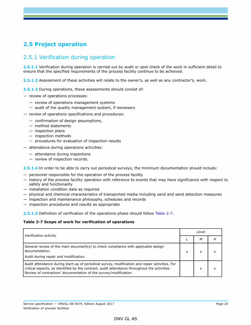
2.5.1.5 Definition of verification of the operations phase should follow Table 2-7.
Table 2-7 Scope of work for verification of operations
LevelVerification activity
L M H
General review of the main document(s) to check compliance with applicable designdocumentation.
Audit during repair and modification.x x x
Audit attendance during start-up of periodical survey, modification and repair activities. Forcritical aspects, as identified by the contract, audit attendance throughout the activities.Review of contractors' documentation of the survey/modification.
x x

Service specification — DNVGL-SE-0479. Edition August 2017 Page 21Verification of process facilities
DNV GL AS
LevelVerification activity
L M H
Review of the main document(s) to check compliance with applicable codes and standards.Audit attendance during start-up and performance of periodical survey, modification andrepair activities. For critical aspects, as identified by the contract, full attendance throughoutthe preparations of and the activities. Issuing of independent confirmation documentation ofthe survey/modification.
x
2.5.1.6 Verification during operations is carried out to confirm that the process facility continue to meet theOwner's specified requirements.
2.5.1.7 Annual assessments may be carried out to confirm that any deterioration of the process facility arewithin acceptable limits and that the facility continues to be fit for the intended purpose.
Guidance note:Annual assessments do not necessarily involve annual inspections as such regular inspections may not be required under a risk-based inspection strategy. Annual assessments may be limited to review of records confirming that the process facility have beenoperated within its design limits.
---e-n-d---o-f---g-u-i-d-a-n-c-e---n-o-t-e---
2.5.1.8 Additional assessments should be carried out to confirm that any damage, deterioration ormodification to the pipeline system or other systems does not render the process facility unsuitable for theintended purpose.
2.6 Verification documents
2.6.1 General
2.6.1.1 The hierarchy of verification document is given in DNVGL-SE-0474. The descriptions of the content ofthese documents as well as examples of document forms are given in App.C to this specification.

Service specification — DNVGL-SE-0479. Edition August 2017 Page 22Verification of process facilities
DNV GL AS
APPENDIX A SELECTION OF VERIFICATION LEVEL
A.1 General
A.1.1 General principles
A.1.1.1 The selection of the level of verification depends on the risk level of each of the elements that havean impact on the management of risks to the asset.
A.1.1.2 Verification shall direct greatest effort at those elements of the asset where the risk is highest andwhose failure or reduced performance will have the most significant impact on the project objective andgoals, e.g.:
— safety risks— environmental risks— economic risks.
A.1.1.3 Suitable selection factors include, but are not limited to, the:
a) Overall safety and other objectives for the asset.b) Assessment of the risks associated with the asset and the measures taken to reduce these risks.c) Degree of technical innovation in the asset.d) Experience of the contractors in carrying out the work.e) Quality management systems of the owner and its contractors.
A.1.1.4 Due to the diversity of various process facilities, their contents, their degree of innovation, thegeographic location, et cetera, it is not possible to give precise guidelines on how to decide what level ofverification is appropriate for each particular process facility.
A.1.1.5 Therefore, guidance is given as a series of questions that should be answered when deciding theappropriate level of verification for a process facility. This list is not exhaustive and other questions should beadded to the list if appropriate for a particular process facility.
A.1.1.6 It must be emphasised that the contribution of each element should be judged qualitatively and/or quantitatively. Wherever possible quantified risk assessment data should be used to provide a justifiablebasis for any decisions made.
A.1.1.7 Depending of the stage of the project, the activities may not have taken place yet in which case thequestions can also be posed in another form, i.e. “Is …. planned to be?”
A.2 Trigger questions
A.2.1 Overall project objective and goalsa) Does the safety objective address the main safety goals?b) Does the safety objective establish acceptance criteria for the level of risk acceptable to the owner?c) Is this risk (depending on the process facility and its location) measured in terms of human injuries as
well as environmental, economic and political consequences?Guidance note:Substitute Safety Objective with other relevant objectives for the project, and go through all of them.
---e-n-d---o-f---g-u-i-d-a-n-c-e---n-o-t-e---

Service specification — DNVGL-SE-0479. Edition August 2017 Page 23Verification of process facilities
DNV GL AS
A.2.2 Assessment of riska) Has a systematic review been carried out to identify and evaluate the probabilities and consequences of
failures in the process facility?b) Has this review judged the contribution of each element qualitatively and or quantitatively and used,
where possible, quantified risk assessment data to provide a justifiable basis for any decisions made?c) Does the extent of the review reflect the risk level of the process facility, the planned operation and
previous experience with similar process facilities?d) Does this review identify the risk to the operation of the process facility and to the health and safety of
personnel associated with it or in its vicinity?e) Has the extent of the identified risks been reduced to a level as low as reasonably practicable by means
of one or both of:
— Reduction in the probability of failure?— Mitigation of the consequences of failure?
f) Has the result of the systematic review of the risks been measured against the owner’s safety (or other)objective?
g) Has the result of this review been used in the selection of the appropriate verification activity level?
A.2.3 Technical innovationa) Has the degree of technical innovation in the process facility been considered?b) Has it been considered that risks to the process facility are likely to be greater with a high degree of
technical innovation than with a process facility designed, manufactured and installed to well-knowncriteria in well-known waters?
c) Have factors been considered in the selection of the appropriate verification level such as:
— Degree of difficulty in achieving technical requirements.— Knowledge of similar process facilities.— Effect of the new process facility on the surrounding area.
A.2.4 Contractors’ experiencea) Has the degree of risk to the process facility been considered where design, construction or installation
contractors are inexperienced?b) Has the degree of risk been considered where the contractors are experienced but not in similar work?c) Has the degree of risk been considered where the work schedule is tight?
A.2.5 Quality management systemsa) Have all parties involved in the process facility implemented an adequate quality management system to
ensure that gross errors in the work are limited?b) Do these parties include the:
— Owner?— Design contractor?— Construction contractors?— Installation contractor?— Operator?
c) Do the factors being considered when evaluating the adequacy of the quality management systeminclude:

Service specification — DNVGL-SE-0479. Edition August 2017 Page 24Verification of process facilities
DNV GL AS
— Whether or not an ISO 9000 or equivalent certified system is in place?— Results from external audits?— Results from internal audits?— Experience with contractors’ previous work?— Project work force familiarity with the quality management system?

Service specification — DNVGL-SE-0479. Edition August 2017 Page 25Verification of process facilities
DNV GL AS
APPENDIX B DETAILED EXAMPLE SCOPE OF WORK TABLES FORVERIFICATION
B.1 General
B.1.1 Introduction
B.1.1.1 This appendix gives the format of the detailed scope of work tables that shall be defined for eachparticular project.
B.1.1.2 For project scenarios or components not covered in this appendix, similar tables with the samedegree of detail shall be made.
B.1.1.3 If any of the activities are moved from one phase to another, then this must be identified clearlyidentified on the list where it is removed. Similarly, the detailed list for the phase to where it is moved shallbe amended.
Guidance note:Typically, contractual boundaries may give natural splits of activities between phases. However, then it is then even more importantto ensure that there is a traceably as to which phases what activity belong and that this is also conveyed to the contractors also.
---e-n-d---o-f---g-u-i-d-a-n-c-e---n-o-t-e---
B.2 Description of terms used in the scope of work tables
B.2.1 General
B.2.1.1 The following abbreviations have been used. The definitions of which are given subsequently:
A = auditS = surveillanceR = review
B.2.1.2 These abbreviations are DNV GL’s preferred terms and normally will be used in DNV GL-generateddocuments. However, other terms, for example monitoring or witnessing, will be used by DNV GL if theseare the terms commonly used in documents, such as Inspection and Test Plans, generated by others. In thatcase, it is expected that these other terms are defined in these documents.
B.2.2 Audit
B.2.2.1 Systematic and independent examination to determine whether quality activities and related resultscomply with planned arrangements and whether these arrangements are implemented effectively and aresuitable to achieve objectives (ISO 8402:1994).
Guidance note:This activity differs from the surveillance by being focused on the adherence to and completeness and robustness of theprocedures and not on the actual result of the procedure (although this is not ignored). Further, the audit is normally a ‘one-off’activity as opposed to the continuity in monitoring.
---e-n-d---o-f---g-u-i-d-a-n-c-e---n-o-t-e---

Service specification — DNVGL-SE-0479. Edition August 2017 Page 26Verification of process facilities
DNV GL AS
B.2.3 Surveillance
B.2.3.1 Continual monitoring and verification of the status of an entity and analysis of records to ensure thatspecified requirements are being fulfilled (ISO 8402:1994).
Guidance note:Other commonly used terms for surveillance are monitoring or witnessing.
---e-n-d---o-f---g-u-i-d-a-n-c-e---n-o-t-e---
B.2.3.2 The amount of work involved in surveillance is not described in detail in the tables. This shall be partof the final contractual scope of work which shall define the frequency of surveillance based on the overallsurveillance and the quality control performed by other parties as well as DNV GL’s experience.
B.2.3.3 The following shall be used to describe the frequency if nothing else is specifically defined:
S1 = surveillance on a visit basis, e.g. once per week or sample review 10-20%.S2 = surveillance frequency minimum once per day or review of 50-60%.S3 = surveillance frequency minimum once per shift or review of 100% of items.
Guidance note:These surveillance frequencies may be modified to correspond with production work flow.
---e-n-d---o-f---g-u-i-d-a-n-c-e---n-o-t-e---
B.2.4 Review
B.2.4.1 Systematic examination of reports and documentation against a project defined verification basis.The depth of review will depend both on the type of document and the level of involvement.
B.2.4.2 The following shall be used to describe the extent of the review if nothing else is specifically defined:
I = for information only.R1 = review of principles and general aspects.R2 = comprehensive review.
Guidance note:Review of production records does not guarantee their correctness. It is a confirmation to DNV GL that the manufacturer and orsub-contractor has preformed the required activity and issued a report.
---e-n-d---o-f---g-u-i-d-a-n-c-e---n-o-t-e---
B.2.4.3 Documents that are reviewed by DNV GL will, unless otherwise agreed, not be signed and stamped.
B.3 Overall project management
B.3.1 General
B.3.1.1 The project quality management documentation, if part of scope, should be available for review atthe early stages of the project, preferably before design is underway, to ensure that the necessary controlsare in place.

Service specification — DNVGL-SE-0479. Edition August 2017 Page 27Verification of process facilities
DNV GL AS
Table B-1 Overall project management
LevelItem Description
Low Medium High
1. Project quality management documentation R1 R2 R2
2. Project quality management system A
3. Sub-contractor control R2
4. Interface controls R1 R2
5. Methods of information flow R1
B.4 Design
B.4.1 Design verification
B.4.1.1 Table B-2 describes the issues to be reviewed and Table B-3 identifies the extent of independentanalyses and calculations included in the three verification levels.
B.4.1.2 Table B-4 describes the issues to be verified in relation to flow assurance as an additional verificationservice.
B.4.2 Low level design verification
B.4.2.1 The initial low level design verification consists of a detailed document review of the design basis,risk assessment and analysis documentation, quality management documentation and (if they exist) methodor design philosophy documents. The presumed high risk aspects of the project shall be identified by DNVGL from the initial review and conveyed to the Owner and designer for discussion and agreement on correctunderstanding.
B.4.2.2 The subsequent verification consists of document review of the calculations and analysis methodsused to conclude the high risk aspects. Other design documents are used as information and a few will bespot checked for confirmation of the quality control.
B.4.2.3 Implementation of the transfer of conclusions from design calculations and reports into drawings andspecifications is not included.
B.4.3 Medium level design verification
B.4.3.1 Medium level design verification consists of a review of all main design documents related to safetyand integrity. Less critical aspects will be spot checked. The review will be detailed for high risk aspects andindependent checks will be performed.
B.4.3.2 Implementation of the conclusions from design calculations and reports into drawings andspecifications will be included on a spot check basis.

Service specification — DNVGL-SE-0479. Edition August 2017 Page 28Verification of process facilities
DNV GL AS
B.4.4 High level design verification
B.4.4.1 High level design verification consists of a full review of most of the produced documents relatedto safety and integrity. The review will be detailed for all high risk aspects and independent checks will beperformed.
B.4.4.2 Implementation of the conclusions from design calculations and reports into drawings andspecifications is included.
B.4.4.3 The main specifications are also checked for clearness and ambiguity.
Table B-2 Verification of process facilities design
LevelItem Description
Low Medium High
General
1. Safety objective I R1 R2
2. Description of process facilities and overall project organisation. I I I
3. Design basis. I R1 R2
4. Risk assessment and or emergency preparedness analysis and identificationof critical aspects. R1 R1 R2
5. Document register. I I I
Specifications for design
6.Design philosophies for the facilities, typically; Active and Passive fireprotection, Safety systems (FGS/ESD/PSD/PCS), Shutdown logic, Processdesign, Piping design, Relief and Blowdown, Material choice etc.
R1 R1 R2
Process safety functions
7.
P&IDs and associated documentation to confirm:
— appropriate safety devices are specified (typically in accordance with APIRP 14C/ISO 10418)
— adequate margins between operating and design conditions— trip settings are suitable for the intended level of protection— the status or position of valves does not impair system safety (locked
open/closed; fail open/close/fixed; interlocking; etc.).
R1 R2 R2
8.P&IDs to confirm that shutdown valves are located such that systems canbe clearly segregated and give suitable segment boundaries and conformsto the assumptions and basis of the risk analysis.
R1 R2 R2
9. P&IDs showing block valves, isolating devices, etc. required formaintenance operations. I R1 R2
10. Process and safety shutdown C&E diagrams or equivalent have appropriateshutdown logic. I R1 R2
Pressure relieving devices

Service specification — DNVGL-SE-0479. Edition August 2017 Page 29Verification of process facilities
DNV GL AS
LevelItem Description
Low Medium High
11. Data sheets to confirm sizing case, set pressure, backpressure and valvetype. R2 R2 R2
12.
Process design calculations for the relieving devices (relief valve, rupturedisc, etc.) to confirm the sizing case (full flow, gas blowby, fire, thermalrelief, etc.) is appropriate and the specified capacity adequate.
I R1 R2
13.
Process design calculations focusing on relieving device inlet line pressuredrop, outlet line size and backpressure. I R1 R2
Blowdown and flare 1) design
14. P&IDs to confirm that isolatable sections are provided with remote operatedblowdown possibilities as required by the flare and blowdown philosophy R1 R2 R2
15.
Flare and blowdown documentation to confirm that:
— time to depressurise is appropriate 2)
— calculated flow rates do not exceed the system capacity— calculated backpressures do not exceed the system limits— flare system is separated into appropriate systems (e.g. high and low
pressure, hot and cold, wet and dry flare systems)— minimum temperature and material choice is acceptable.
I R1 R2
16.P&IDs to confirm that flare, relief and blowdown lines are self draining,and where low points are unavoidable these have an appropriate drainconnection with locked open isolation valve.
R1 R2 R2
17. Flare K-O drum sizing calculations and drawings to confirm that there willbe no unacceptable liquid carry over to the flare tip. I R1 R2
18.P&IDs to confirm a suitable purge gas system to prevent air ingress isspecified for the flare system (including alarms for low flow, back-upsystems, etc.)
R1 R1 R2
19 Flare radiation calculations (for worst case flow and wind conditions) toconfirm these are acceptable I R1 R2
20. Flare noise calculations to confirm compliance with noise requirements ofthe verification basis (as applicable). I I R1
21. P&IDs to confirm ‘snuffing’ package is specified for cold vent tip whereappropriate I R1 R2
22. Flare ignition system to confirm that acceptable reliability of ignition will beachieved during all possible scenarios. I R1 R2
HIPPS systems
23. HIPPS application in accordance with the requirements of the verificationbasis. R1 R1 R1
24.
Reliability documentation to confirm that the HIPPS system is independentof other systems and have the same or better safety reliability as apressure relief device system. Alternatively, confirm compliance with IEC61508 and that specified SIL level is achieved in accordance with HIPPSspecification.
R1 R1 R2

Service specification — DNVGL-SE-0479. Edition August 2017 Page 30Verification of process facilities
DNV GL AS
LevelItem Description
Low Medium High
25. System documentation to confirm that requirements for testing have beenaccounted for. I R1 R2
26.Process design calculations to confirm that the specified response times ofprotective systems are sufficiently short to prevent unacceptable processconditions.
I R1 R2
Utility systems
27.
P&ID’s to confirm that adequate safety requirements are implementedfor utility systems interfacing hydrocarbon systems such as e.g. heatingmedium, cooling medium, drains systems, pneumatic system, hydraulicsystems, chemical injection systems.
I R1 R2
Piping
28.Pipe stress analysis guidelines/philosophy/work instructions in order toidentify needs for additional information/guidelines not outlined in thespecified piping code or project standards.
R1 R1 R2
29.
Selection of pipe stress analysis reports and pipe stress isometrics in orderto ensure that the analysis meet the requirement outlined in the specificpiping code, project standards and project pipe stress analysis philosophy.A typical selection may be based on large pipe size, large temperaturedifferential and piping with high pressure. Piping/process line list, pipingcritical line list and project P&ID’s will normally be used as basis for thisselection.
R1 R2 R2
30.
Review of a selected number of piping classes in the piping materialspecification. Typical this work will consist of spot check of tabulated wallthickness against temperature, pressure, corrosion allowance, impacttesting and “fit for service”. Relevant material data sheets (MDS) will alsobe considered. If present, the selection may be based on sophisticatedmaterials not widely used (known) outside the offshore-industry. Typical arepiping made of Super Duplex, 6Mo, Titanium and GRP.
I R1 R2
Passive fire protection
31.PFP on vessels, piping, supports and structure and withhold this withassumptions in risk analysis ( if relevant), design accidental loads in eachspecific area, vessel integrity requirements, blowdown time etc.
R1 R1 R2
32.PFP drawings versus specified criteria for heat loads and exposure time,and withhold this against material approval certificates w.r.t thickness andapplication requirements.
I R1 R2
33.
Separation by fire divisions of individual process areas (if relevant) forcompliance with project requirements and withhold this with assumptionsin risk analysis (if relevant) and active fire fighting philosophy (firewaterdemand).
R1 R1 R2
34. Requirements for passive fire protection resulting from the project specificdesign philosophy and Risk Analysis R1 R1 R2
Active fire protection

Service specification — DNVGL-SE-0479. Edition August 2017 Page 31Verification of process facilities
DNV GL AS
LevelItem Description
Low Medium High
35.Layout drawings to confirm adequacy of firewater main routing andadequate number and location of manual fire fighting equipment such asfire extinguishers, hydrants, hoses and monitors.
R1 R1 R2
36. Adequacy of selected manual fire fighting equipment. R1 R1 R2
37. Sizing basis for firewater demand to cover process areas. R1 R1 R2
38. Firewater P&ID’s to confirm requirements for supply to equipment andareas, separation of supplies, bypass and isolation possibilities. R1 R1 R2
39. Firewater hydraulic calculations to confirm adequate capacity and pressureto all discharge points. I R1 R2
40. Layout drawings to confirm adequate location of deluge valves, choice ofareas to be protected and identification of dedicated equipment protection. R1 R1 R2
41. Nozzle type and density in each area. I R1 R1
42. Foam and other fire extinguishing systems w.r.t. application, type,concentration and capacity. R1 R1 R2
Fire and gas detection
43.Type (suitability), number and location of detectors taking into accountvoting philosophy and alarm levels. Review location and number of manualfire alarm stations.
R1 R1 R2
Shutdown logic
44.
Cause and effect diagrams, or similar, covering the following aspects:
— PSD; shutdown according to API RP 14C/ISO 10418— PSD; avoid unacceptable cascading effects— PSD; high level shutdown to include lower levels/individual shutdown
levels— FGS; initiation of relevant fire extinguishing systems, shutdown actions,
ignition prevention, alarm systems, blowdown (as applicable)— ESD; shutdown of production plant, DHSV’s/SSIV’s as appropriate and
initiation of blowdown.
I R1 R2
Process equipment
45. Specifications and data sheets for equipment like pressure vessels, valves,heat exchangers, pumps, compressors and turbines. - R1 R2
46. Manufacturers design documentation to verify that project specificationsand applicable standards are implemented correctly w.r.t. integrity. - I R1
Materials
47. Systems description manual and PFD’s. I I I
48.— Materials selection report— corrosion protection report— coating and insulation specification (e.g. coating procedures).
R1 R2 R2

Service specification — DNVGL-SE-0479. Edition August 2017 Page 32Verification of process facilities
DNV GL AS
LevelItem Description
Low Medium High
49.— Internal corrosion assessment, calculation and assessment of corrosion
rate where applicable (or spot check)— corrosion monitoring system.
I R1 R1
50.
— Materials specification— welding specification— NDT-specification
for critical components.
R1 R2 R2
Hazardous area classification
51.
Hazardous area classification drawings and source of release schedule (asapplicable) to verify extent and type of zones, location of ventilation inlets/outlets, overpressure/air locks for local equipment rooms. Cross checkagainst P&ID’s to confirm classification of vents, segregation of drainagesystem etc.
R1 R2 R2
Abbreviations used in the table:
PSD = process shutdown system
FGS = fire and gas system
ESD = emergency shutdown system
PCS = process control system
DHSV = down hole safety valve
SSIV = subsea isolation valve
HIPPS = high integrity pressure protection system
SIL = safety integrity level
C&E = cause and effect
1) The majority of the following activities are also applicable to cold vent systems.2) This will include a cross-check against the results of the individual blowdown orifice sizing and timing
calculations, relief valve capacity calculations, piping backpressure calculations reviewed as part of otherverification activities.
Table B-3 Independent analyses and calculations
LevelItem Activity Description
Low Medium High
1. Blodown analysisPrepare a simplified model of the process plant in orderto review critical blowdown design features such as theflare headers, flare KO Drum and flare radiation.
x
2. Piping flexibilityanalysis
Prepare a model of critical lines to evaluate pipe stressand support layout in accordance with ASME B31.3 Part5 Flexibility and Support.
x

Service specification — DNVGL-SE-0479. Edition August 2017 Page 33Verification of process facilities
DNV GL AS
LevelItem Activity Description
Low Medium High
3. Analysis ofpressure vessels
Prepare a structural model of important pressure vesselsto evaluate the structural capacity of critical areas fornormal and/or accidental loads as found critical duringthe design of design review.
x
x = analysis and check will be included in the scope of work (if relevant)
Table B-4 Flow assurance or other functional requirements
LevelItem Description
Low Medium High
1. Design documentation and analyses with respect to planned and unplannedshutdowns and the effect this may have on hydrate- and wax-formation. I R1 R2
2. Design strategy implemented with respect to avoidance of hydrate- and waxformation. I R1 R2
3. Plant vulnerability to erosion effects, e.g. inlet arrangement (chokes,headers, inlet separator), sand jetty system and produced water system. I R1 R2
B.5 Construction
B.5.1 General
B.5.1.1 Construction consists of a number of different site activities and their associated documentation.
B.5.1.2 Table B-5 and Table B-6 give the scope of work for construction and commissioning respectively.
B.5.1.3 For construction, verification lists similar those shown hereafter shall be made for the specifics of theparticular project.
B.5.2 Construction verification
B.5.2.1 [2.4] specifies the typical documentation to be submitted before, during and after construction.
B.5.2.2 Verification of process facilities construction activities includes:
— initial activities— inspection activities— final activities.
B.5.2.3 The initial activities include the review of procedures, attendance during qualification of procedures(e.g. MPQT) and personnel (e.g. welders) and other start-up activities. The inspection activities are the siteattendance and the final activities are the (continuous) review of production results and records and thecompletion of documentation and reports.

Service specification — DNVGL-SE-0479. Edition August 2017 Page 34Verification of process facilities
DNV GL AS
B.5.3 Low level construction verification
B.5.3.1 For low level verification, the procedure review consists of a review of the construction managementprocedures and confirmation that the most important aspects of the main specifications have been includedin the procedures. For the qualification of procedures and personnel DNV GL will not attend the actualqualification, but will review the results.
B.5.3.2 During the construction, DNV GL’s verification will be performed during site visits. The verificationwill focus on the high risk items and aspects identified in the detailed scope of work tables.
B.5.3.3 The subsequent verification of the final activities will be by spot-checks of the production recordsincluding non-conformance logs, and results from audits, both contractors’ internal audits or auditsperformed by other parties.
B.5.4 Medium level construction verification
B.5.4.1 For medium level verification, the procedure review consists of a detailed review of constructionmanagement procedures. Other important procedures will be spot checked to confirm that the mostimportant aspects of the specifications have been included.
B.5.4.2 For the qualification of procedures and personnel DNV GL will visit the main qualifications and reviewthe results.
B.5.4.3 During construction, DNV GL’s verification will be performed by full time attendance at the mainsites. The verification will focus on the high risk items and aspects as identified in the detailed scope of worktables.
B.5.4.4 Verification of the final activities will be by review of the production records including non-conformance logs, and results from audits, both contractor’s internal audits or audits performed by otherparties, from the main sites and spot checks of the same from other important sites.
B.5.5 High level construction verification
B.5.5.1 For high level verification, the procedure review consists of a detailed review of constructionmanagement procedures. Other procedures will be spot checked to confirmation that important aspects ofthe specifications have been included.
B.5.5.2 For qualification of procedures and personnel DNV GL will attend the main qualifications, visit otherqualifications and review the results.
B.5.5.3 During construction, DNV GL’s verification will be performed by full time attendance at the mainsites and by visits to the other important sites. Verification will focus on the high risk items and aspects asidentified in the detailed scope of work tables.
B.5.5.4 Verification of the final activities will be by detailed review of the production records including thenon-conformance log, and results from audits, both contractor’s internal audits or audits performed by otherparties, from the main sites and spot checks of the same from other important sites.

Service specification — DNVGL-SE-0479. Edition August 2017 Page 35Verification of process facilities
DNV GL AS
B.5.6 Verification of work in progress
B.5.6.1 The monitoring by the owner during construction relates to the activities of the contractor. Themonitoring of these activities by DNV GL relates not only to the contractor’s activities but also to themonitoring of these activities carried out by the owner.
B.5.6.2 The emphasis placed on the various activities in the verification plan varies depending on:
— any areas of concern revealed during design verification— any areas of concern revealed during the audit of the owner’s or contractor’s quality management systems— the progress of construction— the findings of the contractor surveillance personnel.
B.5.6.3 Many contractors have adequate quality control systems and quality control departments, withcompetent personnel to perform, required assessments of suppliers and sub-contractors. In such case, allverification work need not be done by DNV GL personnel. Where applicable, the various inspections maybe carried out by competent persons other than DNV GL personnel. In that situation DNV GL’s verificationactivities can be confined to:
— reviewing the competence of the contractor’s personnel,— auditing their working methods and their performance of that work, and— reviewing the documents produced by them.
B.5.6.4 DNV GL personnel will spend more time in areas where problems have occurred, or are consideredlikely to occur. Conversely, less time is spent in areas where the likelihood of problems is considered lower.
B.5.7 DNV GL final report
B.5.7.1 All the scopes of work tables for construction end with a point entitled “Issue of DNV GL visit report”.This item is not related to the production process, but is intended as a reminder to the DNV GL (or others)inspection personnel that a final report on their verification activities is required to finish the work.
Table B-5 Verification of process facilities construction
LevelItem Description
Low Medium High
Initial activity
1. Management system documents. R1 R2 R2
2. Quality system audit at relevant manufacturers and sub-suppliers. - A A
3. Specifications and procedures. R1 R2 R2
4. Technical meeting/kick-off meeting and review of manufacturingdocuments. R1 R1 R2
Inspection activities
Availability of process safety functions by
5. Process instrumentation with PSD/ESD/HIPPS functions installed as per theP&IDs. S1 S2 S3
6. Pressure relieving devices installed as per the P&IDs. S1 S2 S3

Service specification — DNVGL-SE-0479. Edition August 2017 Page 36Verification of process facilities
DNV GL AS
LevelItem Description
Low Medium High
7. Process and safety shutdown valves (ESDVs/PSDVs) installed as per theP&IDs. S1 S2 S3
8. Block valves, isolating devices, etc. installed as per the P&IDs. - - S1
Availability of pressure relieving devices
9. Test records to confirm that relieving devices are of the correct type, sizing(e.g. orifice size for relief valves) and set pressure. S1 S2 S3
10. Inlet pipework to relieving devices located satisfactorily in relation topotential restrictions (e.g. above liquid levels, vessel internals, etc.). S1 S2 S3
Availability of blowdown and flare 1) system
11. Each isolatable section provided with an automatic blowdown valve asspecified in the P&IDs. S1 S2 S3
12. Flare, relief and blowdown lines are self draining, and low points have anappropriate drain connection with locked open isolation valve. - S1 S2
13. Mechanical completion records to confirm that blowdown orifices areinstalled in accordance with the design (size and location). R1 R2 R2
14. Blowdown orifices installed in accordance with the design (size andlocation). S1 S2
15. Confirm by review of mechanical completion records, fabrication isometrics,etc. that flare and blowdown pipework have been installed in accordancewith P&IDs.
R1 R2 R2
16. Flare and blowdown pipework installed in accordance with P&IDs andblowdown calculations (incl. free draining lines). - - S1
17. Inlet pipework to blowdown valves located satisfactorily in relation topotential restrictions (e.g. above liquid levels, vessel internals, etc.). S1 S2 S3
18. Manufacturer’s as-built drawings to confirm that flare K-O drums have beenfabricated in accordance with design documentation. R1 R2 R2
19. Inspection and/or review of mechanical completion records to confirm thatpurge gas system is installed as per P&IDs (incl. alarms, back-up systems,etc.).
S1 S2 S3
20. Manufacturer’s as-built drawings to confirm that flare tip has beenfabricated in accordance with design documentation. R1 R2 R2
21. Mechanical completion records to confirm that a ‘snuffing’ package has beeninstalled on the cold vent as per P&IDs3). R1 R2 R2
22. ‘Snuffing’ package installed on the cold vent as per P&IDs. S3
23. Mechanical completion records to confirm that a flare ignition system hasbeen installed as per P&IDs. R1 R2 R2
24. Flare ignition system installed as per P&IDs. - - S3
HIPPS systems

Service specification — DNVGL-SE-0479. Edition August 2017 Page 37Verification of process facilities
DNV GL AS
LevelItem Description
Low Medium High
25. Mechanical completion records to confirm that the HIPPS system has beeninstalled as per P&IDs. R1 R2 R2
26. HIPPS system installed as per P&IDs. - - S3
Piping
27. Review of the welding and NDE/NDT specifications related to piping toensure that the specifications meet the minimum requirements of therelevant piping code, project standards and national regulations.
- R1 R2
28. Review of the pressure test philosophy to ensure that the pressure testphilosophy meet the minimum requirements of the relevant piping code,project standards and national regulations.
- R1 R2
29. Mechanical completion records to confirm that pressure tests have beenperformed according to philosophy. - R1 R2
Open drains system
30. Open drain boxes located according to appropriate hazardous areas. S1 S2 S2
31. Water seals installed in accordance with design drawings. S1 S2 S2
Passive fire protection
32. Quality surveillance system in place to document that thicknessmeasurements are systematically performed. R1 R2 R2
33. Application manual. - R1 R2
34. Application performed in accordance with the application manual. - S1 S1
Active fire protection
35. Location of deluge valves and manual fire fighting equipment such as fireextinguishers, hydrants, hoses and monitors are in accordance with designdrawings.
S1 S2 S3
36. Deluge nozzles appropriately located in relation to obstructions and specificequipment protection. S1 S2 S3
37. Mechanical completion records to confirm that the firewater main systemhas been installed as per P&IDs. R1 R1 R2
38. Appropriate access provided to all manual isolation valves in the firewatersystem. S1 S2 S3
Fire and gas detection
39. Location of fire and gas detectors. Mechanical completion records to confirmthat type is in accordance with design drawings. S1 S2 S3
Hazardous area classification
40. Hazardous area classification as shown on drawings is appropriate and notchanged by alterations in equipment location. Follow-up that assumptions indesign are correctly implemented.
S1 S2 S3
Final activities

Service specification — DNVGL-SE-0479. Edition August 2017 Page 38Verification of process facilities
DNV GL AS
LevelItem Description
Low Medium High
41. Manufacturing and testing records. R1 R2 R2
42. Issue of DNV GL visit report.
1) The majority of the following activities are also applicable to cold vent systems.
Table B-6 Verification of process facilities commissioning
LevelItem Description
Low Medium High
Inspection activities
Operability of process safety functions by
1.Loop check records and calibration/trip setting records to confirm thatprocess instrumentation with a PSD/ESD function is set in accordance withthe P&IDs.
R1 R2 R2
2.Commissioning records to confirm that isolation valves are positioned suchthat they can not prevent operation of safety devices (locked open/closed;interlocking; etc.) as per P&IDs.
R1 R2 R2
3. Isolation valves positioned such that they can not prevent operation ofsafety devices (locked open/closed; interlocking; etc.) as per P&IDs. S1 S2 S3
4.Commissioning records to confirm that all actuated valves with a safetyfunction (PSD, ESD, HIPPS, blowdown, etc.) fail to a safe position as per theP&IDs.
R1 R2 R2
5. Witness testing to confirm that all actuated valves with a safety function(PSD, ESD, HIPPS, blowdown, etc.) fail to a safe position as per the P&IDs. S1 S2 S3
6. Commissioning records to confirm that PSD system functions are inaccordance with SAFE charts or PSD cause and effect diagrams. R1 R2 R2
7. Witness testing to confirm that PSD system functions in accordance withSAFE Charts or PSD Cause and Effect Diagrams S1 S2 S3
Operability of blowdown and flare1) system
8.Commissioning records to confirm that blowdown valves are initiated andtiming sequences are in accordance with the blowdown report and causeand effect diagrams.
R1 R2 R2
9.Witness testing to confirm that blowdown valves are initiated and timingsequences are in accordance with the blowdown report and cause and effectdiagrams.
S1 S2 S3
10. Commissioning records to confirm that purge gas low flow alarms and back-up systems functions satisfactorily. - R1 R2
11. Witness testing to confirm that purge gas low flow alarms and back-upsystems functions satisfactorily. - - S1
12. Commissioning records to confirm that flare tip ‘flame-out’ alarms functionsatisfactorily. - R1 R2

Service specification — DNVGL-SE-0479. Edition August 2017 Page 39Verification of process facilities
DNV GL AS
LevelItem Description
Low Medium High
13. Witness testing to confirm that flare tip ‘flame-out’ alarms functionsatisfactorily. - - S1
14. Commissioning records to confirm that the cold vent ‘snuffing’ packagefunctions satisfactorily. - R1 R2
15. Witness testing to confirm that the cold vent ‘snuffing’ package functionssatisfactorily. - - S1
HIPPS system
16. Commissioning records to confirm that the HIPPS system functionssatisfactorily. R1 R2 R2
17. Witness testing to confirm that HIPPS system function satisfactorily. - S1 S2
Active fire protection
18. Commissioning records to confirm that the active fire protection systemsfunctions satisfactorily. R1 R2 R2
19. Witness testing to confirm that active fire protection systems functionsatisfactorily. S1 S2 S3
Fire and gas detection
20. Commissioning records to confirm that F&G system functions are inaccordance with cause and effect diagrams. R1 R2 R3
21. Witness testing to confirm that FGS system functions in accordance withcause and effect diagrams. S1 S2 S3
Final activities
22. Fabrication records. R1 R2 R2
23. Testing records. R1 R2 R2
24. Issue of DNV GL visit report.
1) The majority of the following activities are also applicable to cold vent systems.
B.6 Operations
B.6.1 General
B.6.1.1 No tables are provided for the operation phase. The project specific tables will be based on the workperformed leading up to the verification report and the contractual arrangement for the project.

Service specification — DNVGL-SE-0479. Edition August 2017 Page 40Verification of process facilities
DNV GL AS
APPENDIX C EXAMPLES OF VERIFICATION DOCUMENTS
C.1 Verification documents
C.1.1 Validity of verification documents
C.1.1.1 Verification documents are, in principle, documents confirming that an examination has been carriedout, and are valid only at the time of issue.
C.1.2 Statement of conformity
C.1.2.1 A statement of conformity can be issued on completion of each particular project phase, or naturalpart thereof, and shall be based on a dedicated verification report.
C.1.2.2 A statement of conformity shall be issued as a formal statement confirming that verification ofdocuments and or activities, has found that the process facility, a part thereof, or a verification activity,complies with the requirements applicable for that particular project phase.
C.1.2.3 The technical information on a statement of conformity shall contain:
— process facility description and item number, if relevant— application (operational limitations and conditions of use) for which the process facility is intended— codes and standards with which the process facilities have been found to comply— level of verification— an appendix containing the accompanying dedicated verification report.
C.1.2.4 A statement of conformity shall be signed by the DNV GL project manager.An example of a typical statement of conformity is shown at the end of this appendix.
C.1.3 Verification reports
C.1.3.1 Verification reports are issued to confirm that the relevant product or service has been completed inaccordance with specified requirements.
C.1.3.2 The report shall include information such as:
— product or service description and item number, if relevant,— application (operational limitations and conditions of use) for which the product or service is intended,— codes and standards with which the product or service has been verified against,— clear statement of the conclusion from the verification (does it or does it not meet the specified
requirements),— codes and standards used as reference.,— documentation on which the verification report is based (documents, drawings, correspondence, including
revision numbers),— project-specific scope of work tables— any comments,— identification of any non-conformances.
C.1.3.3 The verification report shall always be dated and have two signatures, the originator and the DNV GLinternal verifier.

Service specification — DNVGL-SE-0479. Edition August 2017 Page 41Verification of process facilities
DNV GL AS
C.1.4 Verification comments
C.1.4.1 Reviews of documents shall be reported using verification comment sheets (often called VerComs).These documents give details to the client of aspects of process facilities design and construction that DNVGL:
a) Considers do not meet the specified requirements.b) Does not have enough information to make a decision.c) Offers advice based on its own experience.
C.1.4.2 Only in the first two instances does DNV GL expect a response from the owner or its contractors.
C.1.4.3 An example of a typical verification comment sheet is shown at the end of this appendix.
C.1.5 Audit report
C.1.5.1 Audit reports are issued to confirm that a company’s quality management system has been reviewedto confirm compliance (or not) with the nominated standard and project requirements. In addition, the auditreports confirm compliance with the documented procedures and that these procedures are effective.
C.1.5.2 Audit reports shall contain information such as whether:
— the company has a documented quality system— this quality system been certified by an accredited certification body for the product (or service) in
question— the quality system covers the following quality assurance elements adequately for the product:
— organisation,— authority and responsibility— job descriptions for key persons— internal quality audits— documentation change control— job instructions and procedures— non-conformance and corrective action
— there are adequate procedures for activities such as:
— calibration of equipment— material identification and marking— control of special processes such as welding, NDT PWHT— non-conformance identification and handling— inspection status— final inspection
— the company’s facilities are, in general, considered adequate for the scope of supply
— a quality plan been prepared for the order concerned
— the purchaser or their appointed inspection agency are planned to attend the works
— there are any problem areas identified.
An example of a typical audit report is shown at the end of this appendix.

Service specification — DNVGL-SE-0479. Edition August 2017 Page 42Verification of process facilities
DNV GL AS
C.1.6 Visit reports
C.1.6.1 Visit reports are documentation and recording of attendance activity by DNV GL.Guidance note:Visit reports are and may be called by different names. Examples are inspection release note, survey report, inspection certificate,site report, etc.
---e-n-d---o-f---g-u-i-d-a-n-c-e---n-o-t-e---
C.1.6.2 A visit report shall contain enough information to identify clearly the product or service that hasbeen examined, the operating conditions or specifications to which it has been examined and the conclusionreached by DNV GL.
C.1.6.3 The visit report shall be printed on the relevant form and shall contain as much information aspossible in accordance with the standard headings in the form. In addition, the report number shall beshown.
C.1.6.4 An example of a typical Visit Report is shown at the end of this appendix.
C.2 Use of quality management systems
C.2.1 General
C.2.1.1 The assurance of process facility integrity and function requires that gross errors during design,construction and operation be minimised. The likelihood of gross errors shall be reduced in a systematicmanner by the operation of a quality management system adequate for the work being carried out.
C.2.1.2 Quality management systems frequently are documented at three levels:
— the quality manual and related procedures document how the organisation, as a whole, manages thequality of all its products and services
— the quality plan documents the specific procedures related to a particular project— the inspection and test plan documents how the quality control activities for a particular project shall be
carried out and recorded.
C.2.2 Quality plans
C.2.2.1 The basic function of a quality plan is to be a memory aid in the management of a project. Inan organisation with many quality procedures for a variety of functions the quality plan states those thatare applicable to that particular project. The quality plan acts as a route map through the complexities ofmanagement of the project and highlights those activities relevant to quality management.
C.2.2.2 The project quality plan normally consists of two parts; firstly, a narrative description of the meansof controlling the project, and secondly, a tabular description of the inspections and tests to be carried outduring the work.
C.2.2.3 The quality plan should address:
— organisational details of the project— authorities and responsibilities of key personnel— interfaces between, the client, contractors, sub-contractors and third parties— quality assurance activities placed on sub-contractors
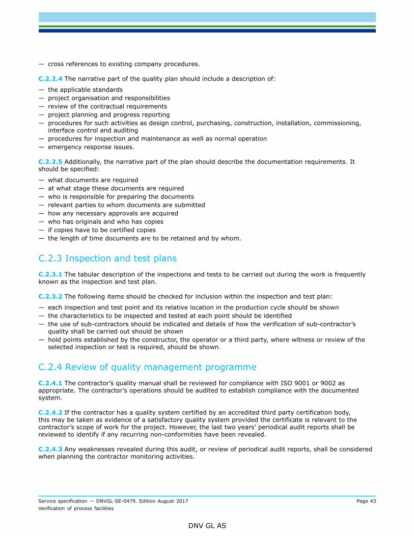
Service specification — DNVGL-SE-0479. Edition August 2017 Page 43Verification of process facilities
DNV GL AS
— cross references to existing company procedures.
C.2.2.4 The narrative part of the quality plan should include a description of:
— the applicable standards— project organisation and responsibilities— review of the contractual requirements— project planning and progress reporting— procedures for such activities as design control, purchasing, construction, installation, commissioning,
interface control and auditing— procedures for inspection and maintenance as well as normal operation— emergency response issues.
C.2.2.5 Additionally, the narrative part of the plan should describe the documentation requirements. Itshould be specified:
— what documents are required— at what stage these documents are required— who is responsible for preparing the documents— relevant parties to whom documents are submitted— how any necessary approvals are acquired— who has originals and who has copies— if copies have to be certified copies— the length of time documents are to be retained and by whom.
C.2.3 Inspection and test plans
C.2.3.1 The tabular description of the inspections and tests to be carried out during the work is frequentlyknown as the inspection and test plan.
C.2.3.2 The following items should be checked for inclusion within the inspection and test plan:
— each inspection and test point and its relative location in the production cycle should be shown— the characteristics to be inspected and tested at each point should be identified— the use of sub-contractors should be indicated and details of how the verification of sub-contractor’s
quality shall be carried out should be shown— hold points established by the constructor, the operator or a third party, where witness or review of the
selected inspection or test is required, should be shown.
C.2.4 Review of quality management programme
C.2.4.1 The contractor’s quality manual shall be reviewed for compliance with ISO 9001 or 9002 asappropriate. The contractor’s operations should be audited to establish compliance with the documentedsystem.
C.2.4.2 If the contractor has a quality system certified by an accredited third party certification body,this may be taken as evidence of a satisfactory quality system provided the certificate is relevant to thecontractor’s scope of work for the project. However, the last two years’ periodical audit reports shall bereviewed to identify if any recurring non-conformities have been revealed.
C.2.4.3 Any weaknesses revealed during this audit, or review of periodical audit reports, shall be consideredwhen planning the contractor monitoring activities.

Service specification — DNVGL-SE-0479. Edition August 2017 Page 44Verification of process facilities
DNV GL AS
C.2.4.4 Surveillance of the continuing acceptability of the contractor’s quality management system is carriedout by observing a selection of audits carried out by the contractor as part of its internal audit system. Theaudits to be observed should be selected over the length of the project at suitable intervals and should coveras wide a selection of activities as possible.
C.2.4.5 Contractor’s inspection and test plans for the various activities undertaken during their scope of workfor the pipeline shall be reviewed and accepted, if adequate.
C.3 Document forms
C.3.1 Introduction
C.3.1.1 The end of this appendix includes example forms for use by DNV GL in verification.
C.3.1.2 The following forms are included:
—
a) Statement of conformity.b) Verification comments sheet.c) Audit report.d) Visit report.

Service specification — DNVGL-SE-0479. Edition August 2017 Page 45Verification of process facilities
DNV GL AS
C.3.2 Statement of conformity
EXAMPLE

Service specification — DNVGL-SE-0479. Edition August 2017 Page 46Verification of process facilities
DNV GL AS
C.3.3 Verification comments sheet

Service specification — DNVGL-SE-0479. Edition August 2017 Page 47Verification of process facilities
DNV GL AS
C.3.4 Audit report
EXAMPLE
Service specification — DNVGL-SE-0479. Edition August 2017 Page 48Verification of process facilities
DNV GL AS
EXAMPLE

Service specification — DNVGL-SE-0479. Edition August 2017 Page 49Verification of process facilities
DNV GL AS
C.3.5 Visit report
EXAMPLE

Cha
nges
– h
isto
ric
Service specification — DNVGL-SE-0479. Edition August 2017 Page 50Verification of process facilities
DNV GL AS
CHANGES – HISTORICThere are currently no historical changes for this document.

About DNV GLDriven by our purpose of safeguarding life, property and the environment, DNV GL enablesorganizations to advance the safety and sustainability of their business. We provide classification,technical assurance, software and independent expert advisory services to the maritime, oil & gasand energy industries. We also provide certification services to customers across a wide rangeof industries. Operating in more than 100 countries, our experts are dedicated to helping ourcustomers make the world safer, smarter and greener.
SAFER, SMARTER, GREENER