Embed Size (px)
Citation preview
Heat & Glo LifeStyle Collection • Twilight-II-B • 2108-900 Rev. E • 11/06 1
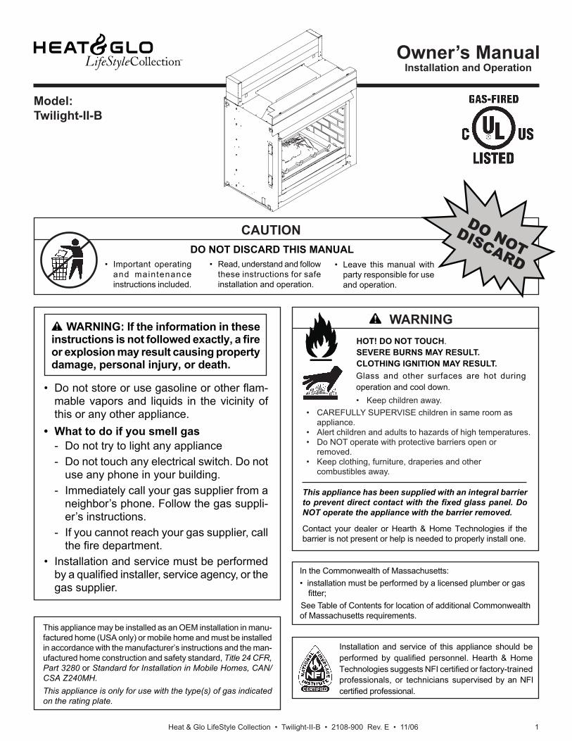
Model:Twilight-II-B
• Do not store or use gasoline or other fl am-mable vapors and liquids in the vicinity of this or any other appliance.
• What to do if you smell gas - Do not try to light any appliance - Do not touch any electrical switch. Do not
use any phone in your building.- Immediately call your gas supplier from a
neighbor’s phone. Follow the gas suppli-er’s instructions.
- If you cannot reach your gas supplier, call the fi re department.
• Installation and service must be performed by a qualifi ed installer, service agency, or the gas supplier.
WARNING: If the information in these instructions is not followed exactly, a fi re or explosion may result causing property damage, personal injury, or death.
This appliance has been supplied with an integral barrier to prevent direct contact with the fi xed glass panel. Do NOT operate the appliance with the barrier removed.
Contact your dealer or Hearth & Home Technologies if the barrier is not present or help is needed to properly install one.
HOT! DO NOT TOUCH. SEVERE BURNS MAY RESULT.CLOTHING IGNITION MAY RESULT.
• CAREFULLY SUPERVISE children in same room as appliance.
• Alert children and adults to hazards of high temperatures.• Do NOT operate with protective barriers open or
removed.• Keep clothing, furniture, draperies and other
combustibles away.
Glass and other surfaces are hot during operation and cool down.• Keep children away.
Owner’s ManualInstallation and Operation
DO NOT DISCARD THIS MANUAL
CAUTION
This appliance may be installed as an OEM installation in manu-factured home (USA only) or mobile home and must be installed in accordance with the manufacturer’s instructions and the man-ufactured home construction and safety standard, Title 24 CFR, Part 3280 or Standard for Installation in Mobile Homes, CAN/CSA Z240MH. This appliance is only for use with the type(s) of gas indicated on the rating plate.
Installation and service of this appliance should be performed by qualifi ed personnel. Hearth & Home Technologies suggests NFI certifi ed or factory-trained professionals, or technicians supervised by an NFI certifi ed professional.
• Leave this manual with party responsible for use and operation.
DO NOTDISCARD
WARNING
• Important operating and maintenance instructions included.
• Read, understand and follow these instructions for safe installation and operation.
In the Commonwealth of Massachusetts:• installation must be performed by a licensed plumber or gas fi tter;
See Table of Contents for location of additional Commonwealth of Massachusetts requirements.
Heat & Glo LifeStyle Collection • Twilight-II-B • 2108-900 Rev. E • 11/062
Congratulations
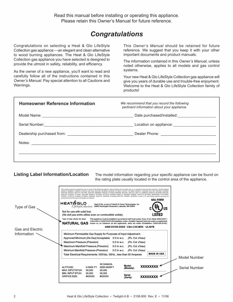
Listing Label Information/Location
Model Name: ___________________________________________ Date purchased/installed: __________________
Serial Number: __________________________________________ Location on appliance: ____________________
Dealership purchased from: _______________________________ Dealer Phone: __________________________
Notes: _______________________________________________________________________________________
_____________________________________________________________________________________________
Congratulations on selecting a Heat & Glo LifeStyle Collection gas appliance —an elegant and clean alternative to wood burning appliances. The Heat & Glo LifeStyle Collection gas appliance you have selected is designed to provide the utmost in safety, reliability, and effi ciency.
As the owner of a new appliance, you’ll want to read and carefully follow all of the instructions contained in this Owner’s Manual. Pay special attention to all Cautions and Warnings.
This Owner’s Manual should be retained for future reference. We suggest that you keep it with your other important documents and product manuals.
The information contained in this Owner’s Manual, unless noted otherwise, applies to all models and gas control systems.
Your new Heat & Glo LifeStyle Collection gas appliance will give you years of durable use and trouble-free enjoyment. Welcome to the Heat & Glo LifeStyle Collection family of products!
Read this manual before installing or operating this appliance. Please retain this Owner’s Manual for future reference.
We recommend that you record the following pertinent information about your appliance.
Gas and Electric Information
Model Number
Serial Number
Type of Gas
The model information regarding your specifi c appliance can be found on the rating plate usually located in the control area of the appliance.
Homeowner Reference Information
Heat & Glo, a of Hearth & Home Technologies, Inc.20802 Kensington Boulevard, Lakeville, MN 55044
brand
Heat & Glo, a of Hearth & Home Technologies, Inc.20802 Kensington Boulevard, Lakeville, MN 55044
brand
Not Not for for use use with with solid solid fuel.fuel.((Ne Ne doit doit pas pas entre entre utilise utilise avec avec un un combustible combustible solide).solide).
This This appliance appliance must must be be installed installed in in accordance accordance with with local local codes, codes, if if any; any; if if not, not, follow follow ANSI ANSI Z223.1Z223.1in in the the USA USA or or CAN/CGA CAN/CGA B149 B149 installation installation codes. codes. (Installer (Installer l’appareil l’appareil selon selon les les codes codes ou ou reglementsreglementslocaux locaux ou, ou, en en l’absence l’absence de de tels tels reglements, reglements, selon selon les les codes codes d’installation d’installation CAN/CGA-B149.)CAN/CGA-B149.)
Type Type of of Gas Gas (Sorte (Sorte De De Gaz)Gaz):
NATURALTURAL GASGAS
MADE MADE IN IN USAUSA
Minimum Minimum Permissible Permissible Gas Gas Supply Supply for for Purposes Purposes of of Input Input Adjustment.Adjustment.Approved Approved Minimum Minimum (De (De Gaz) Gaz) AcceptableAcceptable 0.00.0 in in w.c.w.c. (Po. (Po. Col. Col. d’eau)d’eau)Maximum Maximum Pressure Pressure (Pression)(Pression) 0.00.0 in in w.c.w.c. (Po. (Po. Col. Col. d’eau)d’eau)Maximum Maximum Manifold Manifold Pressure Pressure (Pression)(Pression) 0.00.0 in in w.c.w.c. (Po. (Po. Col. Col. d’eau)d’eau)Minimum Minimum Manifold Manifold Pressure Pressure (Pression)(Pression) 0.00.0 in in w.c.w.c. (Po. (Po. Col. Col. d’eau)d’eau)
Model:Model:(Modele):(Modele):
SerialSerial(Serie):(Serie):
ANSI ANSI Z21XX-XXXX Z21XX-XXXX · · CSA CSA 2.XX-MXX 2.XX-MXX · · UL307BUL307B
XXXXXXXXXXXXXXXXIN IN CANADACANADA
ALTITUDE:ALTITUDE: 0-0000 0-0000 FT.FT. 0000-0000FT.0000-0000FT.MAX. MAX. INPUT INPUT BTUH:BTUH: 00,00000,000 00,00000,000MIN. MIN. INPUT INPUT BTUH:BTUH: 00,00000,000 00,00000,000ORIFICE ORIFICE SIZE:SIZE: #XXXXX#XXXXX #XXXXX#XXXXX XXXXXXXXXXXXXXXX
Total Total Electrical Electrical Requirements: Requirements: 000Vac, 000Vac, 00Hz., 00Hz., less less than than 00 00 AmperesAmperes
This product may be covered by one or more of the following patents: (Nos produits sont couverts par un ou plusieurs des brevets suivants): (United States) 4593510, 4686807, 4766876, 4793322, 4811534, 5000162, 5016609, 5076254, 5113843, 5191877, 5218953, 5263471, 5328356, 5341794, 5347983, 5429495, 5452708, 5542407, 5601073, 5613487, 5647340, 5688568, 5762062, 5775408, 5890485, 5931661, 5941237, 5947112, 5996575, 6006743, 6019099, 6048195, 6053165, 6145502, 6170481, 6237588, 6296474, 6374822, 6413079, 6439226, 6484712, 6543698, 6550687, 6601579, 6672860, 6688302B2, 6715724B2, 6729551, 6736133, 6748940, 6748942, D320652, D445174, D462436; (Canada)1297749, 2195264, 2225408; or other U.S. and foreign patents pending (ou autres brevets americains et etrangers en attente).
Heat & Glo LifeStyle Collection • Twilight-II-B • 2108-900 Rev. E • 11/06 3
= Contains updated information.
Table of Contents
1 Listing and Code Approvals A. Appliance Certifi cation . . . . . . . . . . . . . . . . . . . . . . . . . . . . 4B. Glass Specifi cations . . . . . . . . . . . . . . . . . . . . . . . . . . . . . . 4C. Thermal Performance Data . . . . . . . . . . . . . . . . . . . . . . . . 4D. Air Infi ltration, Water Resistance and Structural Tests . . . 4E. BTU Specifi cations . . . . . . . . . . . . . . . . . . . . . . . . . . . . . . . 4F. High Altitude Installations . . . . . . . . . . . . . . . . . . . . . . . . . . 4G. Non-Combustible Materials Specifi cation. . . . . . . . . . . . . . 4H. Combustible Materials Specifi cation . . . . . . . . . . . . . . . . . 4I. Requirements for the Commonwealth of Massachusetts . . 5
2 Getting Started A. Design and Installation Considerations . . . . . . . . . . . . . . . 6B. Tools and Supplies Needed . . . . . . . . . . . . . . . . . . . . . . . . 6C. Inspect Appliance and Components . . . . . . . . . . . . . . . . . . 6
3 Framing and Clearances A. Selecting Appliance Location . . . . . . . . . . . . . . . . . . . . . . . 7B. Clearances . . . . . . . . . . . . . . . . . . . . . . . . . . . . . . . . . . . . . 8C. Mantel Projections - Indoor only . . . . . . . . . . . . . . . . . . . . 9
4 Termination Locations A. Appliance Opening Minimum Clearances . . . . . . . . . . . . 10
5 Appliance Preparation A. Removing Non-combustible Facing Material Assembly . .11B. Securing and Leveling the Appliance . . . . . . . . . . . . . . . . .11C. Installing Non-combustible Facing Material (Outdoor Side) .
16
6 Gas Information A. Fuel Conversions . . . . . . . . . . . . . . . . . . . . . . . . . . . . . . . 17B. Gas Pressures . . . . . . . . . . . . . . . . . . . . . . . . . . . . . . . . . 17C. Gas Connection . . . . . . . . . . . . . . . . . . . . . . . . . . . . . . . . 17
7 Electrical Information A. Recommendation for Wire . . . . . . . . . . . . . . . . . . . . . . . . 19B. Connecting to the Appliance. . . . . . . . . . . . . . . . . . . . . . . 19C. Optional Accessories . . . . . . . . . . . . . . . . . . . . . . . . . . . . 20D. Intellifi re Ignition System Wiring . . . . . . . . . . . . . . . . . . . . 21E. Junction Box Installation. . . . . . . . . . . . . . . . . . . . . . . . . . 22F. Wall Switch Installation for Fan (Optional) . . . . . . . . . . . . 22
8 Finishing A. Mantel Projections . . . . . . . . . . . . . . . . . . . . . . . . . . . . . . 23B. Facing Material . . . . . . . . . . . . . . . . . . . . . . . . . . . . . . . . . 23
9 Appliance Setup A. Remove Shipping Materials . . . . . . . . . . . . . . . . . . . . . . . 26B. Clean the Appliance . . . . . . . . . . . . . . . . . . . . . . . . . . . . . 26C. Accessories . . . . . . . . . . . . . . . . . . . . . . . . . . . . . . . . . . . 26D. Lava Rock and Ember Placement . . . . . . . . . . . . . . . . . . 26E. Positioning the Logs . . . . . . . . . . . . . . . . . . . . . . . . . . . . 27F. Glass Assembly . . . . . . . . . . . . . . . . . . . . . . . . . . . . . . . . 29G. Grilles and Trim . . . . . . . . . . . . . . . . . . . . . . . . . . . . . . . . 29H. Shutter Settings . . . . . . . . . . . . . . . . . . . . . . . . . . . . . . . . 29
10 Operating Instructions A. Before Lighting Appliance. . . . . . . . . . . . . . . . . . . . . . . . . 30B. Lighting Appliance . . . . . . . . . . . . . . . . . . . . . . . . . . . . . . 31C. After Appliance is Lit . . . . . . . . . . . . . . . . . . . . . . . . . . . . . 32D. Frequently Asked Questions . . . . . . . . . . . . . . . . . . . . . . 32
11 Troubleshooting A. Intellifi re Ignition System . . . . . . . . . . . . . . . . . . . . . . . . . 33
12 Maintaining and Servicing Appliance A. Maintenance Tasks . . . . . . . . . . . . . . . . . . . . . . . . . . . . . . 35
13 Reference Materials A. Appliance Dimension Diagram . . . . . . . . . . . . . . . . . . . . . 37B. Service Parts . . . . . . . . . . . . . . . . . . . . . . . . . . . . . . . . . . 38C. Limited Lifetime Warranty . . . . . . . . . . . . . . . . . . . . . . . . . 41D. Contact Information . . . . . . . . . . . . . . . . . . . . . . . . . . . . . 42
Heat & Glo LifeStyle Collection • Twilight-II-B • 2108-900 Rev. E • 11/064
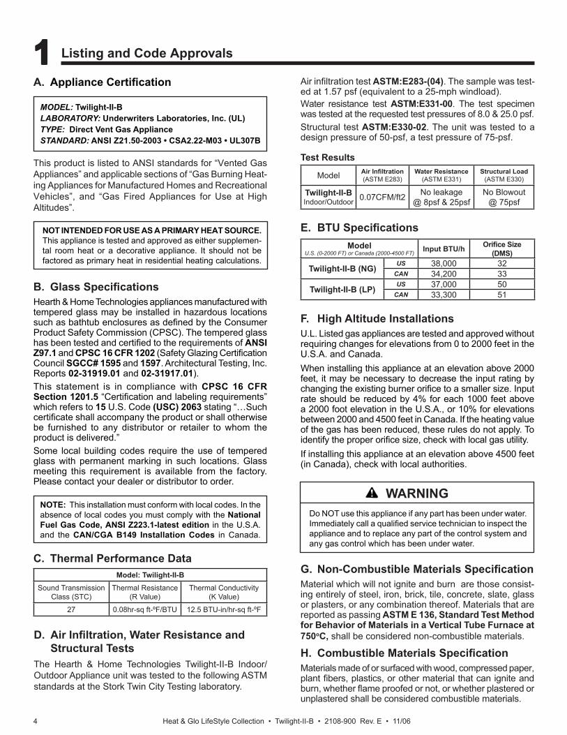
B. Glass Specifi cationsHearth & Home Technologies appliances manufactured with tempered glass may be installed in hazardous locations such as bathtub enclosures as defi ned by the Consumer Product Safety Commission (CPSC). The tempered glass has been tested and certifi ed to the requirements of ANSI Z97.1 and CPSC 16 CFR 1202 (Safety Glazing Certifi cation Council SGCC# 1595 and 1597. Architectural Testing, Inc. Reports 02-31919.01 and 02-31917.01).This statement is in compliance with CPSC 16 CFR Section 1201.5 “Certifi cation and labeling requirements” which refers to 15 U.S. Code (USC) 2063 stating “…Such certifi cate shall accompany the product or shall otherwise be furnished to any distributor or retailer to whom the product is delivered.”Some local building codes require the use of tempered glass with permanent marking in such locations. Glass meeting this requirement is available from the factory. Please contact your dealer or distributor to order.
A. Appliance Certifi cation
NOTE: This installation must conform with local codes. In the absence of local codes you must comply with the National Fuel Gas Code, ANSI Z223.1-latest edition in the U.S.A. and the CAN/CGA B149 Installation Codes in Canada.
NOT INTENDED FOR USE AS A PRIMARY HEAT SOURCE. This appliance is tested and approved as either supplemen-tal room heat or a decorative appliance. It should not be factored as primary heat in residential heating calculations.
F. High Altitude InstallationsU.L. Listed gas appliances are tested and approved without requiring changes for elevations from 0 to 2000 feet in the U.S.A. and Canada.When installing this appliance at an elevation above 2000 feet, it may be necessary to decrease the input rating by changing the existing burner orifi ce to a smaller size. Input rate should be reduced by 4% for each 1000 feet above a 2000 foot elevation in the U.S.A., or 10% for elevations between 2000 and 4500 feet in Canada. If the heating value of the gas has been reduced, these rules do not apply. To identify the proper orifi ce size, check with local gas utility.If installing this appliance at an elevation above 4500 feet (in Canada), check with local authorities.
E. BTU Specifi cations
MODEL: Twilight-II-BLABORATORY: Underwriters Laboratories, Inc. (UL)TYPE: Direct Vent Gas ApplianceSTANDARD: ANSI Z21.50-2003 • CSA2.22-M03 • UL307B
Do NOT use this appliance if any part has been under water. Immediately call a qualifi ed service technician to inspect the appliance and to replace any part of the control system and any gas control which has been under water.
This product is listed to ANSI standards for “Vented Gas Appliances” and applicable sections of “Gas Burning Heat-ing Appliances for Manufactured Homes and Recreational Vehicles”, and “Gas Fired Appliances for Use at High Altitudes”.
D. Air Infi ltration, Water Resistance and Structural Tests
The Hearth & Home Technologies Twilight-II-B Indoor/Outdoor Appliance unit was tested to the following ASTM standards at the Stork Twin City Testing laboratory.
Test Results
C. Thermal Performance DataG. Non-Combustible Materials Specifi cationMaterial which will not ignite and burn are those consist-ing entirely of steel, iron, brick, tile, concrete, slate, glass or plasters, or any combination thereof. Materials that are reported as passing ASTM E 136, Standard Test Method for Behavior of Materials in a Vertical Tube Furnace at 750oC, shall be considered non-combustible materials.
H. Combustible Materials Specifi cationMaterials made of or surfaced with wood, compressed paper, plant fi bers, plastics, or other material that can ignite and burn, whether fl ame proofed or not, or whether plastered or unplastered shall be considered combustible materials.
Air infi ltration test ASTM:E283-(04). The sample was test-ed at 1.57 psf (equivalent to a 25-mph windload). Water resistance test ASTM:E331-00. The test specimen was tested at the requested test pressures of 8.0 & 25.0 psf. Structural test ASTM:E330-02. The unit was tested to a design pressure of 50-psf, a test pressure of 75-psf.
Model: Twilight-II-BSound Transmission
Class (STC)Thermal Resistance
(R Value)Thermal Conductivity
(K Value)
27 0.08hr-sq ft-ºF/BTU 12.5 BTU-in/hr-sq ft-ºF
WARNING
ModelU.S. (0-2000 FT) or Canada (2000-4500 FT) Input BTU/h Orifi ce Size
(DMS)
Twilight-II-B (NG)US 38,000 32
CAN 34,200 33
Twilight-II-B (LP)US 37,000 50
CAN 33,300 51
Model Air Infi ltration(ASTM E283)
Water Resistance(ASTM E331)
Structural Load(ASTM E330)
Twilight-II-BIndoor/Outdoor 0.07CFM/ft2 No leakage
@ 8psf & 25psfNo Blowout
@ 75psf
1 1 Listing and Code Approvals
Heat & Glo LifeStyle Collection • Twilight-II-B • 2108-900 Rev. E • 11/06 5
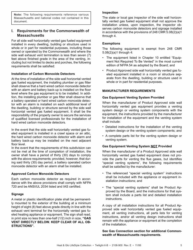
I. Requirements for the Commonwealth of Massachusetts
For all side wall horizontally vented gas fueled equipment installed in every dwelling, building or structure used in whole or in part for residential purposes, including those owned or operated by the Commonwealth and where the side wall exhaust vent termination is less than seven (7) feet above fi nished grade in the area of the venting, in-cluding but not limited to decks and porches, the following requirements shall be satisfi ed:
Installation of Carbon Monoxide DetectorsAt the time of installation of the side wall horizontal vented gas fueled equipment, the installing plumber or gas fi tter shall observe that a hard wired carbon monoxide detector with an alarm and battery back-up is installed on the fl oor level where the gas equipment is to be installed. In addi-tion, the installing plumber or gas fi tter shall observe that a battery operated or hard wired carbon monoxide detec-tor with an alarm is installed on each additional level of the dwelling, building or structure served by the side wall horizontal vented gas fueled equipment. It shall be the responsibility of the property owner to secure the services of qualifi ed licensed professionals for the installation of hard wired carbon monoxide detectors.
In the event that the side wall horizontally vented gas fu-eled equipment is installed in a crawl space or an attic, the hard wired carbon monoxide detector with alarm and battery back-up may be installed on the next adjacent fl oor level.In the event that the requirements of this subdivision can not be met at the time of completion of installation, the owner shall have a period of thirty (30) days to comply with the above requirements; provided, however, that dur-ing said thirty (30) day period, a battery operated carbon monoxide detector with an alarm shall be installed.
Approved Carbon Monoxide DetectorsEach carbon monoxide detector as required in accor-dance with the above provisions shall comply with NFPA 720 and be ANSI/UL 2034 listed and IAS certifi ed.
SignageA metal or plastic identifi cation plate shall be permanent-ly mounted to the exterior of the building at a minimum height of eight (8) feet above grade directly in line with the exhaust vent terminal for the horizontally vented gas fu-eled heating appliance or equipment. The sign shall read, in print size no less than one-half (1/2) inch in size, “GAS VENT DIRECTLY BELOW. KEEP CLEAR OF ALL OB-STRUCTIONS”.
InspectionThe state or local gas inspector of the side wall horizon-tally vented gas fueled equipment shall not approve the installation unless, upon inspection, the inspector ob-serves carbon monoxide detectors and signage installed in accordance with the provisions of 248 CMR 5.08(2)(a)1 through 4.
ExemptionsThe following equipment is exempt from 248 CMR 5.08(2)(a)1 through 4: • The equipment listed in Chapter 10 entitled “Equip-
ment Not Required To Be Vented” in the most current edition of NFPA 54 as adopted by the Board; and
• Product Approved side wall horizontally vented gas fu-eled equipment installed in a room or structure sep-arate from the dwelling, building or structure used in whole or in part for residential purposes.
MANUFACTURER REQUIREMENTS
Gas Equipment Venting System ProvidedWhen the manufacturer of Product Approved side wall horizontally vented gas equipment provides a venting system design or venting system components with the equipment, the instructions provided by the manufacturer for installation of the equipment and the venting system shall include:• Detailed instructions for the installation of the venting
system design or the venting system components; and• A complete parts list for the venting system design or
venting system.
Gas Equipment Venting System NOT ProvidedWhen the manufacturer of a Product Approved side wall horizontally vented gas fueled equipment does not pro-vide the parts for venting the fl ue gases, but identifi es “special venting systems”, the following requirements shall be satisfi ed by the manufacturer:
• The referenced “special venting system” instructions shall be included with the appliance or equipment in-stallation instructions; and
• The “special venting systems” shall be Product Ap-proved by the Board, and the instructions for that sys-tem shall include a parts list and detailed installation instructions.
A copy of all installation instructions for all Product Ap-proved side wall horizontally vented gas fueled equip-ment, all venting instructions, all parts lists for venting instructions, and/or all venting design instructions shall remain with the appliance or equipment at the completion of the installation.
See Gas Connection section for additional Common-wealth of Massachusetts requirements.
Note: The following requirements reference various Massachusetts and national codes not contained in this document.
Heat & Glo LifeStyle Collection • Twilight-II-B • 2108-900 Rev. E • 11/066
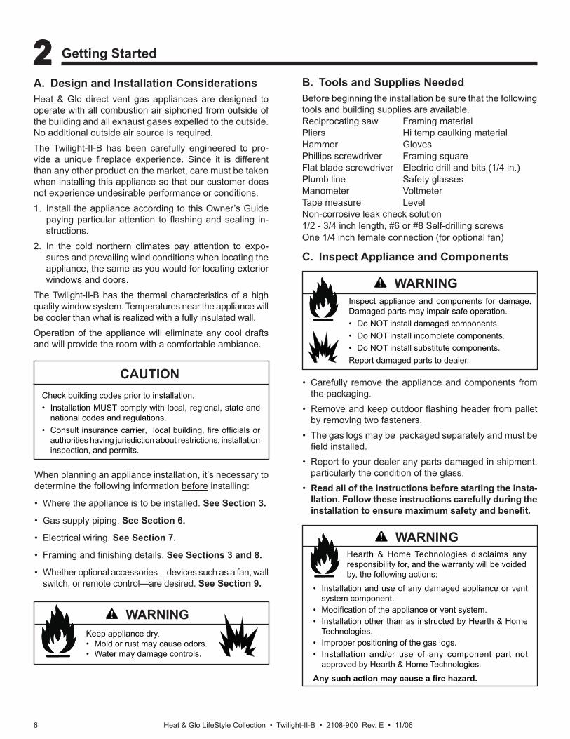
A. Design and Installation ConsiderationsHeat & Glo direct vent gas appliances are designed to operate with all combustion air siphoned from outside of the building and all exhaust gases expelled to the outside. No additional outside air source is required.The Twilight-II-B has been carefully engineered to pro-vide a unique fi replace experience. Since it is different than any other product on the market, care must be taken when installing this appliance so that our customer does not experience undesirable performance or conditions.1. Install the appliance according to this Owner’s Guide
paying particular attention to fl ashing and sealing in-structions.
2. In the cold northern climates pay attention to expo-sures and prevailing wind conditions when locating the appliance, the same as you would for locating exterior windows and doors.
The Twilight-II-B has the thermal characteristics of a high quality window system. Temperatures near the appliance will be cooler than what is realized with a fully insulated wall.Operation of the appliance will eliminate any cool drafts and will provide the room with a comfortable ambiance.
C. Inspect Appliance and Components
When planning an appliance installation, it’s necessary to determine the following information before installing:
• Where the appliance is to be installed. See Section 3.
• Gas supply piping. See Section 6.
• Electrical wiring. See Section 7.
• Framing and fi nishing details. See Sections 3 and 8.
• Whether optional accessories—devices such as a fan, wall switch, or remote control—are desired. See Section 9.
B. Tools and Supplies NeededBefore beginning the installation be sure that the following tools and building supplies are available.Reciprocating saw Framing materialPliers Hi temp caulking materialHammer GlovesPhillips screwdriver Framing squareFlat blade screwdriver Electric drill and bits (1/4 in.)Plumb line Safety glasses Manometer VoltmeterTape measure Level Non-corrosive leak check solution1/2 - 3/4 inch length, #6 or #8 Self-drilling screwsOne 1/4 inch female connection (for optional fan)
• Carefully remove the appliance and components from the packaging.
• Remove and keep outdoor fl ashing header from pallet by removing two fasteners.
• The gas logs may be packaged separately and must be fi eld installed.
• Report to your dealer any parts damaged in shipment, particularly the condition of the glass.
• Read all of the instructions before starting the insta-llation. Follow these instructions carefully during the installation to ensure maximum safety and benefi t.
Check building codes prior to installation.• Installation MUST comply with local, regional, state and
national codes and regulations.• Consult insurance carrier, local building, fi re offi cials or
authorities having jurisdiction about restrictions, installation inspection, and permits.
CAUTION
Keep appliance dry. • Mold or rust may cause odors.• Water may damage controls.
Inspect appliance and components for damage. Damaged parts may impair safe operation.• Do NOT install damaged components.• Do NOT install incomplete components.• Do NOT install substitute components.Report damaged parts to dealer.
Hearth & Home Technologies disclaims any responsibility for, and the warranty will be voided by, the following actions:
• Installation and use of any damaged appliance or vent system component.
• Modifi cation of the appliance or vent system.• Installation other than as instructed by Hearth & Home
Technologies.• Improper positioning of the gas logs.• Installation and/or use of any component part not
approved by Hearth & Home Technologies.
Any such action may cause a fi re hazard.
WARNING
WARNING
WARNING
2 2 Getting Started
Heat & Glo LifeStyle Collection • Twilight-II-B • 2108-900 Rev. E • 11/06 7
GLASS FLUSH TO EXTERIOR INSULATED ENVELOPE
GLASS
A
BB
D
E
C
B
GLASS FLUSH TO EXTERIOR INSULATED ENVELOPE
GLASS
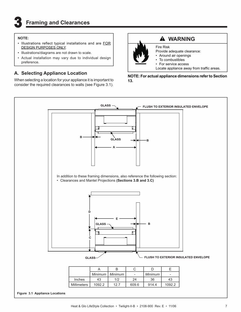
NOTE:• Illustrations reflect typical installations and are FOR
DESIGN PURPOSES ONLY.• Illustrations/diagrams are not drawn to scale.• Actual installation may vary due to individual design
preference.
Fire RiskProvide adequate clearance:• Around air openings• To combustibles• For service accessLocate appliance away from traffi c areas.
A. Selecting Appliance LocationWhen selecting a location for your appliance it is important to consider the required clearances to walls (see Figure 3.1).
Figure 3.1 Appliance Locations
NOTE: For actual appliance dimensions refer to Section 13.
In addition to these framing dimensions, also reference the following section:• Clearances and Mantel Projections (Sections 3.B and 3.C)
WARNING
A B C D EMinimum Minimum - Minimum -
Inches 43 1/2 24 36 43Millimeters 1092.2 12.7 609.6 914.4 1092.2
3 3 Framing and Clearances
Heat & Glo LifeStyle Collection • Twilight-II-B • 2108-900 Rev. E • 11/068
H
K
G
F
J
I
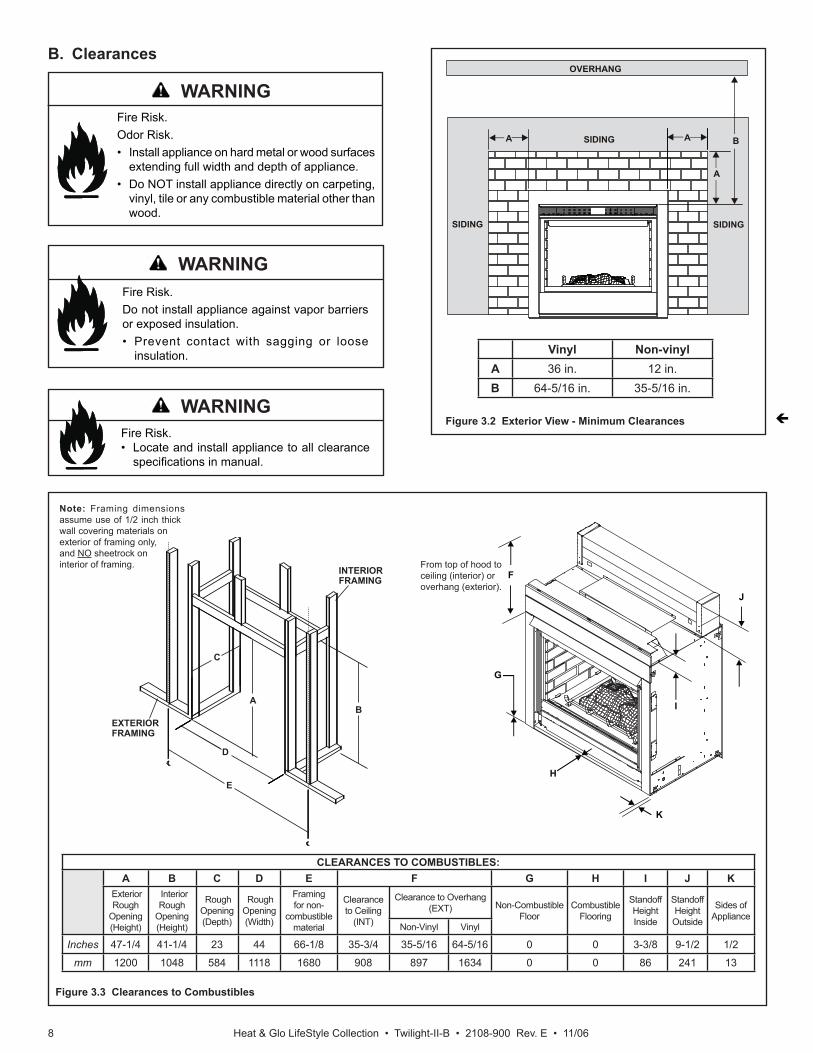
B. Clearances
Figure 3.3 Clearances to Combustibles
Fire Risk.• Locate and install appliance to all clearance
specifi cations in manual.
Fire Risk.Odor Risk.• Install appliance on hard metal or wood surfaces
extending full width and depth of appliance.• Do NOT install appliance directly on carpeting,
vinyl, tile or any combustible material other than wood.
Fire Risk.Do not install appliance against vapor barriers or exposed insulation.• Prevent contact with sagging or loose
insulation.
Note: Framing dimensions assume use of 1/2 inch thick wall covering materials on exterior of framing only, and NO sheetrock on interior of framing. From top of hood to
ceiling (interior) or overhang (exterior).
Figure 3.2 Exterior View - Minimum Clearances
Vinyl Non-vinylA 36 in. 12 in.B 64-5/16 in. 35-5/16 in.
OVERHANG
AA
A
B
SIDING SIDING
SIDING
EXTERIORFRAMING
INTERIORFRAMING
B
E
D
C
A
CLEARANCES TO COMBUSTIBLES:A B C D E F G H I J K
ExteriorRough
Opening (Height)
InteriorRough
Opening (Height)
Rough Opening (Depth)
Rough Opening (Width)
Framingfor non-
combustiblematerial
Clearanceto Ceiling
(INT)
Clearance to Overhang(EXT) Non-Combustible
FloorCombustible
Flooring
Standoff HeightInside
Standoff HeightOutside
Sides of Appliance
Non-Vinyl Vinyl
Inches 47-1/4 41-1/4 23 44 66-1/8 35-3/4 35-5/16 64-5/16 0 0 3-3/8 9-1/2 1/2
mm 1200 1048 584 1118 1680 908 897 1634 0 0 86 241 13
WARNING
WARNING
WARNING
Heat & Glo LifeStyle Collection • Twilight-II-B • 2108-900 Rev. E • 11/06 9
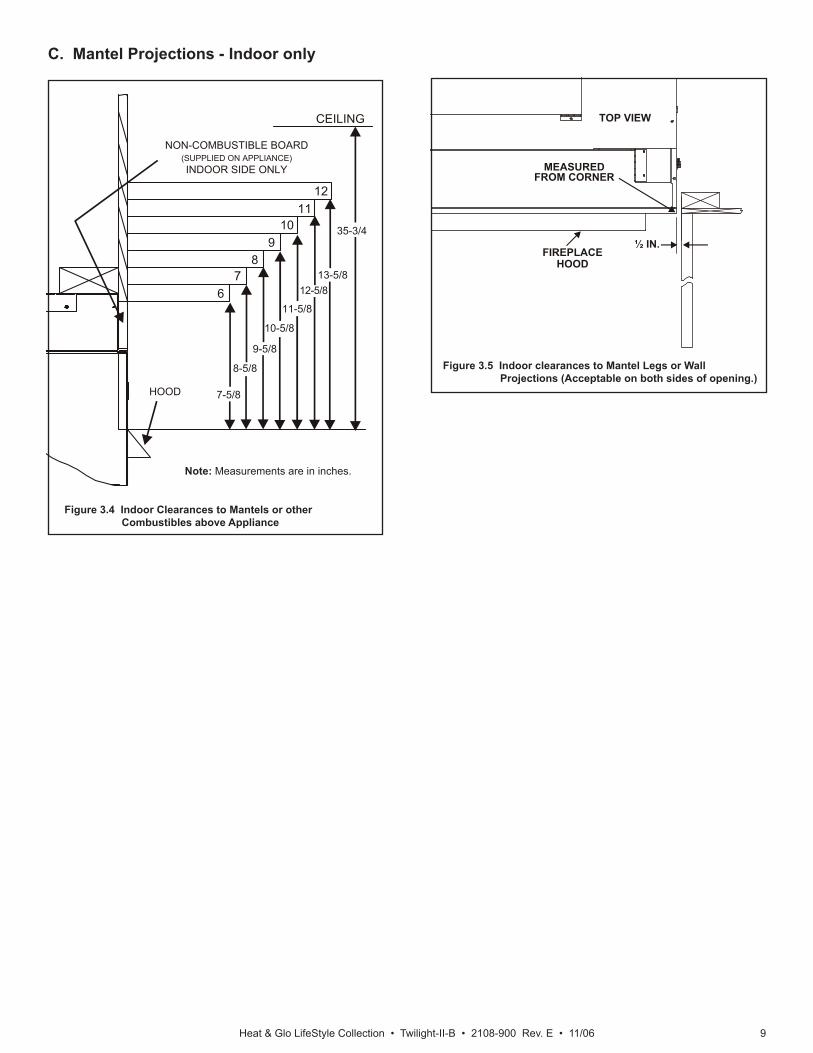
C. Mantel Projections - Indoor only
Figure 3.4 Indoor Clearances to Mantels or other Combustibles above Appliance
Figure 3.5 Indoor clearances to Mantel Legs or Wall Projections (Acceptable on both sides of opening.)
1211
109
87
613-5/8
12-5/8
11-5/8
10-5/8
9-5/8
8-5/8
7-5/8HOOD
NON-COMBUSTIBLE BOARD(SUPPLIED ON APPLIANCE)INDOOR SIDE ONLY
CEILING
35-3/4
MEASUREDFROM CORNER
TOP VIEW
FIREPLACEHOOD
½ IN.
Note: Measurements are in inches.
Heat & Glo LifeStyle Collection • Twilight-II-B • 2108-900 Rev. E • 11/0610
DE
L
FP
A H
MX
J or K
I
A
G
F FP
FP
FPFP
FP
BB
B
4 4 Termination Locations
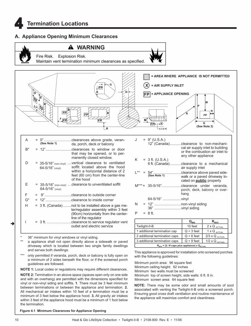
FP = APPLIANCE OPENING
X = AIR SUPPLY INLET
= AREA WHERE APPLIANCE IS NOT PERMITTED
J = 9” (U.S.A.) 12” (Canada) ...........clearance to non-mechani-
cal air supply inlet to building or the combustion air inlet to any other appliance
K = 3 ft. (U.S.A.) 6 ft. (Canada) ...........clearance to a mechanical
air supply inletL** = 54” ...........................clearance above paved side-
walk or a paved driveway lo-cated on public property
M***= 35-5/16”...................clearance under veranda, porch, deck, balcony or over-hang
64-5/16” ..................vinylN = 12” ..........................non-vinyl siding 36” ..........................vinyl sidingP = 8 ft.
(See Note 1)
(See Note 1)
(See Note 2)
* 36” minimum for vinyl windows or vinyl siding.** a appliance shall not open directly above a sidewalk or paved
driveway which is located between two single family dwellings and serves both dwellings.
*** only permitted if veranda, porch, deck or balcony is fully open on a minimum of 2 sides beneath the fl oor, or if the screened porch guidelines are followed.
NOTE 1: Local codes or regulations may require different clearances. NOTE 2: Termination in an alcove space (spaces open only on one side and with an overhang) are permitted with the dimensions specifi ed for vinyl or non-vinyl siding and soffi ts. 1. There must be 3 feet minimum between terminations or between the appliance and termination. 2. All mechanical air intakes within 10 feet of a termination must be a minimum of 3 feet below the appliance hood. 3. All gravity air intakes within 3 feet of the appliance hood must be a minimum of 1 foot below the termination.
This appliance is approved for installation onto screened porches with the following guidelines:
Fire Risk. Explosion Risk.Maintain vent termination minimum clearances as specifi ed.
Figure 4.1 Minimum Clearances for Appliance Opening
NOTE: There may be some odor and small amounts of soot associated with venting the Twilight-II-B onto a screened porch. Ensuring good cross draft ventilation and routine maintenance of the appliance will maximize comfort and cleanliness.
Minimum porch area: 96 square feetMinimum ceiling height: 92 inchesMinimum two walls must be screened Minimum top of screen height, side walls: 6 ft. 8 in.Minimum screen area: 64 square feet
A. Appliance Opening Minimum Clearances
M
N
P
R
Q
FP
A = 0” ...........................clearances above grade, veran-da, porch, deck or balcony
B* = 12” .........................clearances to window or door that may be opened, or to per-manently closed window.
D =.................................vertical clearance to ventilated soffi t located above the hood within a horizontal distance of 2 feet (60 cm) from the center-line of the hood
E = .. .clearance to unventilated soffi t
F = 9” ..........................clearance to outside cornerG* = 12” .........................clearance to inside cornerH = 3 ft. (Canada) ........not to be installed above a gas me-
ter/regulator assembly within 3 feet (90cm) horizontally from the center-line of the regulator
I = 3 ft. ........................clearance to service regulator vent outlet and electric service
35-5/16” (non-vinyl)64-5/16” (vinyl)
35-5/16” (non-vinyl)
64-5/16” (vinyl)
WARNING
QMIN RMAX
Twilight-II-B 10 feet 2 x Q ACTUAL
1 additional termination cap Q + 3 feet 1 x Q ACTUAL
2 additional termination caps Q + 6 feet 2/3 x Q ACTUAL
3 additional termination caps Q + 9 feet 1/2 x Q ACTUAL
RMAX = (2 / # caps plus appliance) x QACTUAL
Heat & Glo LifeStyle Collection • Twilight-II-B • 2108-900 Rev. E • 11/06 11
Fire Risk.• Prevent contact with sagging, loose
insulation.• Do NOT install against vapor barriers or
exposed insulation.
B. Securing and Leveling the Appliance
5 5 Appliance Preparation
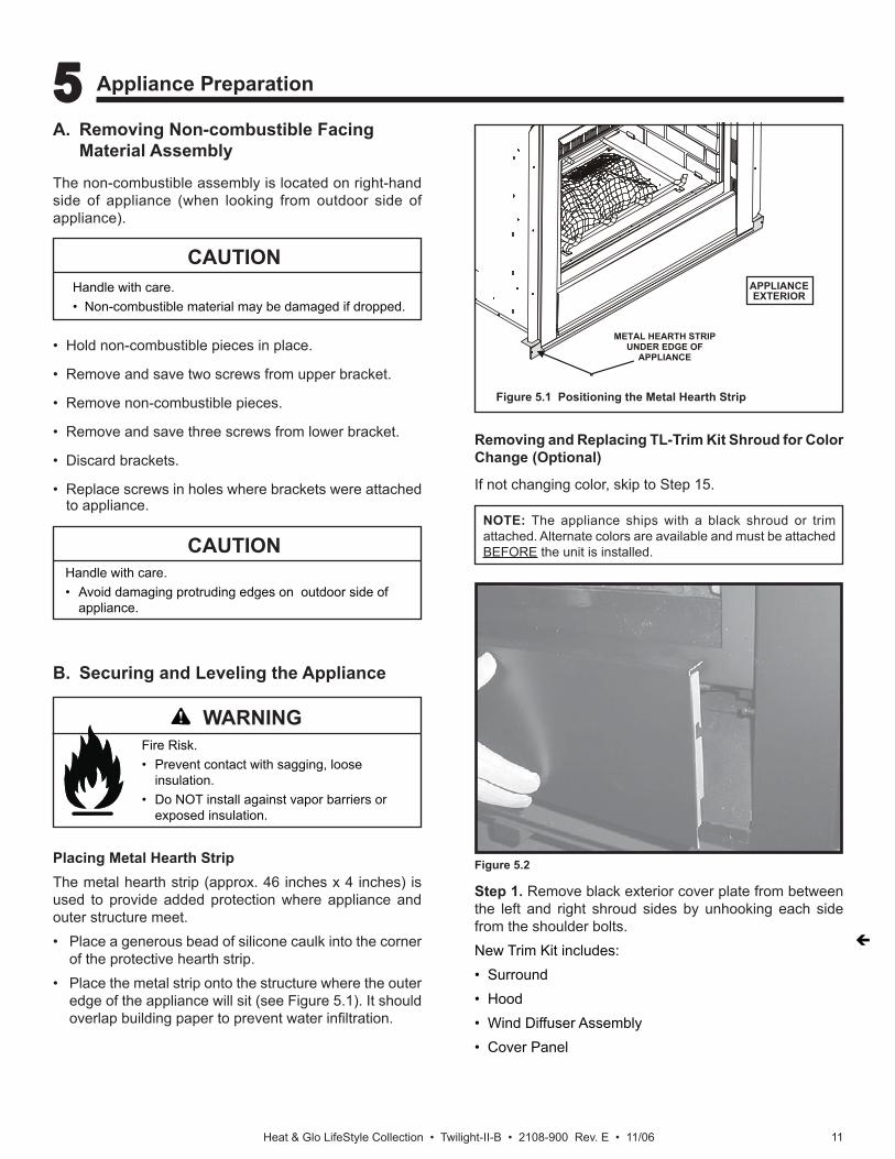
Placing Metal Hearth Strip The metal hearth strip (approx. 46 inches x 4 inches) is used to provide added protection where appliance and outer structure meet.• Place a generous bead of silicone caulk into the corner
of the protective hearth strip.• Place the metal strip onto the structure where the outer
edge of the appliance will sit (see Figure 5.1). It should overlap building paper to prevent water infi ltration.
Figure 5.1 Positioning the Metal Hearth Strip
METAL HEARTH STRIPUNDER EDGE OF
APPLIANCE
APPLIANCEEXTERIOR
NOTE: The appliance ships with a black shroud or trim attached. Alternate colors are available and must be attached BEFORE the unit is installed.
A. Removing Non-combustible Facing Material Assembly
The non-combustible assembly is located on right-hand side of appliance (when looking from outdoor side of appliance).
• Hold non-combustible pieces in place.
• Remove and save two screws from upper bracket.
• Remove non-combustible pieces.
• Remove and save three screws from lower bracket.
• Discard brackets.
• Replace screws in holes where brackets were attached to appliance.
Handle with care.• Non-combustible material may be damaged if dropped.
CAUTION
Handle with care.• Avoid damaging protruding edges on outdoor side of
appliance.
CAUTION
Figure 5.2
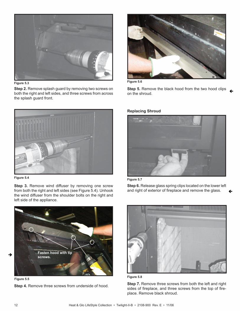
Step 1. Remove black exterior cover plate from between the left and right shroud sides by unhooking each side from the shoulder bolts.New Trim Kit includes:• Surround• Hood• Wind Diffuser Assembly• Cover Panel
Removing and Replacing TL-Trim Kit Shroud for Color Change (Optional)
If not changing color, skip to Step 15.
WARNING
Heat & Glo LifeStyle Collection • Twilight-II-B • 2108-900 Rev. E • 11/0612
Figure 5.3
Figure 5.4
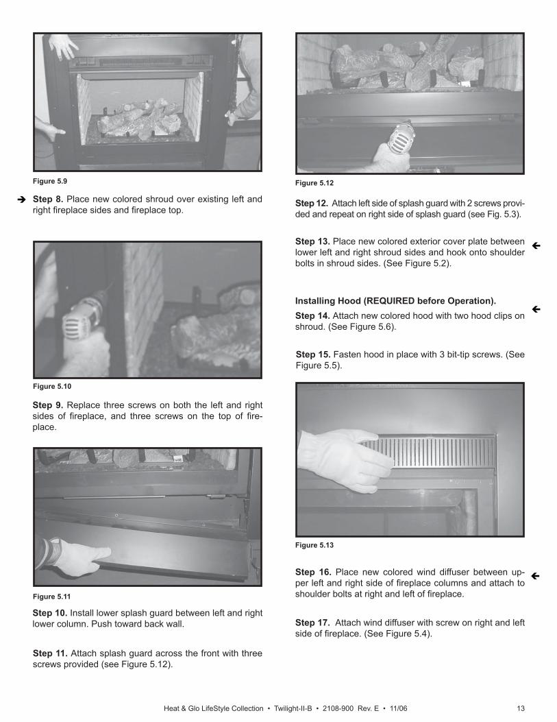
Step 2. Remove splash guard by removing two screws on both the right and left sides, and three screws from across the splash guard front.
Step 3. Remove wind diffuser by removing one screw from both the right and left sides (see Figure 5.4). Unhook the wind diffuser from the shoulder bolts on the right and left side of the appliance.
Step 6. Release glass spring clips located on the lower left and right of exterior of fi replace and remove the glass.
Step 7. Remove three screws from both the left and right sides of fi replace, and three screws from the top of fi re-place. Remove black shroud.
Figure 5.7
Figure 5.8
Replacing Shroud
Figure 5.6
Step 5. Remove the black hood from the two hood clips on the shroud.
Figure 5.5
Step 4. Remove three screws from underside of hood.
Fasten hood with tip screws.
Heat & Glo LifeStyle Collection • Twilight-II-B • 2108-900 Rev. E • 11/06 13
Step 9. Replace three screws on both the left and right sides of fi replace, and three screws on the top of fi re-place.
Step 10. Install lower splash guard between left and right lower column. Push toward back wall.
Step 11. Attach splash guard across the front with three screws provided (see Figure 5.12).
Step 12. Attach left side of splash guard with 2 screws provi-ded and repeat on right side of splash guard (see Fig. 5.3).
Step 13. Place new colored exterior cover plate between lower left and right shroud sides and hook onto shoulder bolts in shroud sides. (See Figure 5.2).
Figure 5.10
Figure 5.11
Figure 5.12
Installing Hood (REQUIRED before Operation).Step 14. Attach new colored hood with two hood clips on shroud. (See Figure 5.6).
Step 8. Place new colored shroud over existing left and right fi replace sides and fi replace top.
Figure 5.9
Step 15. Fasten hood in place with 3 bit-tip screws. (See Figure 5.5).
Figure 5.13
Step 16. Place new colored wind diffuser between up-per left and right side of fi replace columns and attach to shoulder bolts at right and left of fi replace.
Step 17. Attach wind diffuser with screw on right and left side of fi replace. (See Figure 5.4).
Heat & Glo LifeStyle Collection • Twilight-II-B • 2108-900 Rev. E • 11/0614
APPLY RTVSEALANT TO CORNER EDGES
FIREPLACEFLANGE
BEND INFLANGE
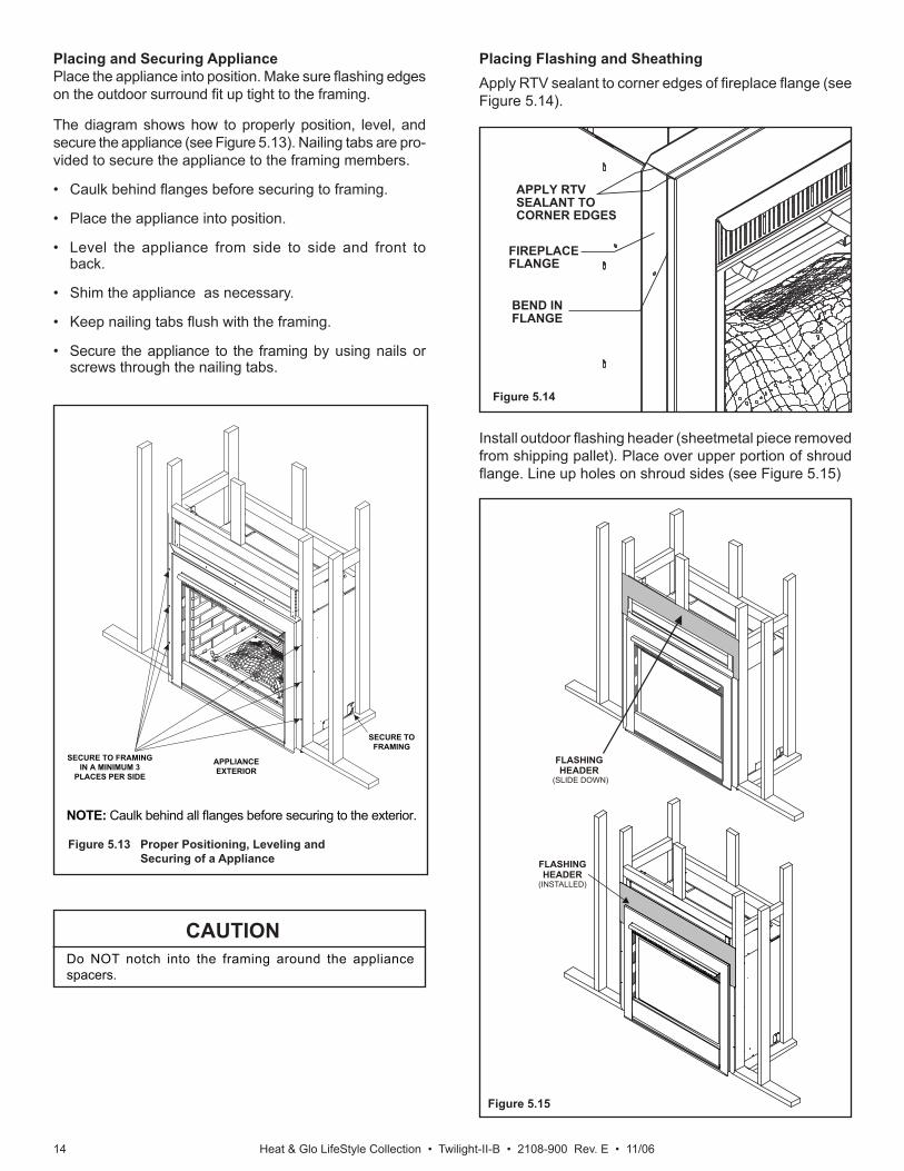
Figure 5.13 Proper Positioning, Leveling and Securing of a Appliance
NOTE: Caulk behind all fl anges before securing to the exterior.
Placing and Securing AppliancePlace the appliance into position. Make sure fl ashing edges on the outdoor surround fi t up tight to the framing.
The diagram shows how to properly position, level, and secure the appliance (see Figure 5.13). Nailing tabs are pro-vided to secure the appliance to the framing members.
• Caulk behind fl anges before securing to framing.
• Place the appliance into position.
• Level the appliance from side to side and front to back.
• Shim the appliance as necessary.
• Keep nailing tabs fl ush with the framing.
• Secure the appliance to the framing by using nails or screws through the nailing tabs.
Placing Flashing and SheathingApply RTV sealant to corner edges of fi replace fl ange (see Figure 5.14).
Figure 5.14
Figure 5.15
Install outdoor fl ashing header (sheetmetal piece removed from shipping pallet). Place over upper portion of shroud fl ange. Line up holes on shroud sides (see Figure 5.15)
Do NOT notch into the framing around the appliance spacers.
CAUTION
APPLIANCEEXTERIOR
SECURE TO FRAMING
SECURE TO FRAMING IN A MINIMUM 3
PLACES PER SIDE
FLASHINGHEADER
(INSTALLED)
FLASHINGHEADER
(SLIDE DOWN)
Heat & Glo LifeStyle Collection • Twilight-II-B • 2108-900 Rev. E • 11/06 15
APPLIANCE
TL-TRIM KIT
HOOD
TOP HOOD
TOP OFFIREPLACE
16-5/16 in.
WALL STUD
HOUSEWRAP
INSULATION
HOUSEWRAP **(BUILDINGPAPER) OVERLAPFLASHING 1 in.
SHEATHING,COMBUSTIBLE
FIREPLACEHEADER
INSULATED FRAMING
STANDOFF
NON-COMBUSTIBLE *SHEATHING
12 in.
FLASHINGHEADER
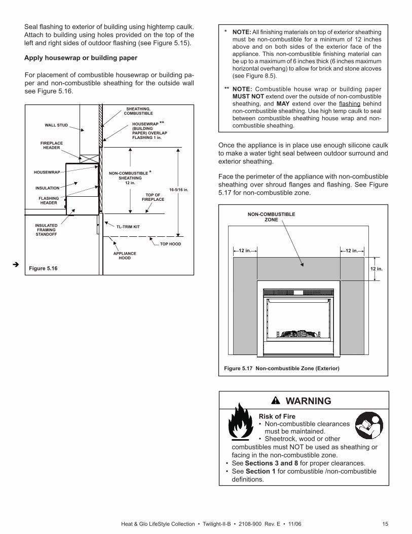
For placement of combustible housewrap or building pa-per and non-combustible sheathing for the outside wall see Figure 5.16.
Seal fl ashing to exterior of building using hightemp caulk. Attach to building using holes provided on the top of the left and right sides of outdoor fl ashing (see Figure 5.15).
Apply housewrap or building paper
* NOTE: All fi nishing materials on top of exterior sheathing must be non-combustible for a minimum of 12 inches above and on both sides of the exterior face of the appliance. This non-combustible fi nishing material can be up to a maximum of 6 inches thick (6 inches maximum horizontal overhang) to allow for brick and stone alcoves (see Figure 8.5).
** NOTE: Combustible house wrap or building paper MUST NOT extend over the outside of non-combustible sheathing, and MAY extend over the fl ashing behind non-combustible sheathing. Use high temp caulk to seal between combustible sheathing house wrap and non-combustible sheathing.
Figure 5.16
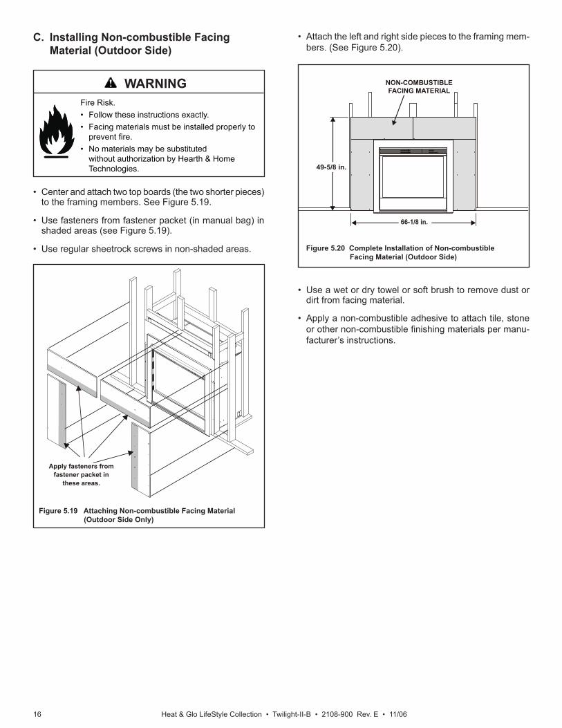
Figure 5.17 Non-combustible Zone (Exterior)
12 in.
12 in.
12 in.
NON-COMBUSTIBLEZONE
Face the perimeter of the appliance with non-combustible sheathing over shroud fl anges and fl ashing. See Figure 5.17 for non-combustible zone.
Risk of Fire • Non-combustible clearances
must be maintained.• Sheetrock, wood or other
combustibles must NOT be used as sheathing or facing in the non-combustible zone.
• See Sections 3 and 8 for proper clearances.• See Section 1 for combustible /non-combustible
defi nitions.
Once the appliance is in place use enough silicone caulk to make a water tight seal between outdoor surround and exterior sheathing.
WARNING
Heat & Glo LifeStyle Collection • Twilight-II-B • 2108-900 Rev. E • 11/0616
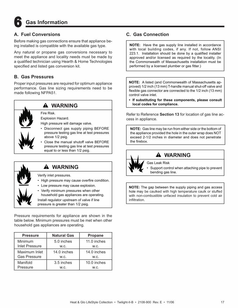
C. Installing Non-combustible Facing Material (Outdoor Side)
• Attach the left and right side pieces to the framing mem-bers. (See Figure 5.20).
Figure 5.19 Attaching Non-combustible Facing Material (Outdoor Side Only)
• Use a wet or dry towel or soft brush to remove dust or dirt from facing material.
• Apply a non-combustible adhesive to attach tile, stone or other non-combustible fi nishing materials per manu-facturer’s instructions.
Figure 5.20 Complete Installation of Non-combustible Facing Material (Outdoor Side)
66-1/8 in.
49-5/8 in.
NON-COMBUSTIBLEFACING MATERIAL
Fire Risk.• Follow these instructions exactly.• Facing materials must be installed properly to
prevent fi re.• No materials may be substituted
without authorization by Hearth & Home Technologies.
• Center and attach two top boards (the two shorter pieces) to the framing members. See Figure 5.19.
• Use fasteners from fastener packet (in manual bag) in shaded areas (see Figure 5.19).
• Use regular sheetrock screws in non-shaded areas.
Apply fasteners fromfastener packet in
these areas.
WARNING
Heat & Glo LifeStyle Collection • Twilight-II-B • 2108-900 Rev. E • 11/06 17
NOTE: Have the gas supply line installed in accordance with local building codes, if any. If not, follow ANSI 223.1. Installation should be done by a qualifi ed installer approved and/or licensed as required by the locality. (In the Commonwealth of Massachusetts installation must be performed by a licensed plumber or gas fi tter.)
A. Fuel ConversionsBefore making gas connections ensure that appliance be-ing installed is compatible with the available gas type.Any natural or propane gas conversions necessary to meet the appliance and locality needs must be made by a qualifi ed technician using Hearth & Home Technologies specifi ed and listed gas conversion kit.
B. Gas PressuresProper input pressures are required for optimum appliance performance. Gas line sizing requirements need to be made following NFPA51.
Fire Risk.Explosion Hazard.High pressure will damage valve.• Disconnect gas supply piping BEFORE
pressure testing gas line at test pressures above 1/2 psig.
• Close the manual shutoff valve BEFORE pressure testing gas line at test pressures equal to or less than 1/2 psig.
C. Gas Connection
Verify inlet pressures.• High pressure may cause overfi re condition.• Low pressure may cause explosion.• Verify minimum pressures when other
household gas appliances are operating.Install regulator upstream of valve if line pressure is greater than 1/2 psig.
6 6 Gas Information
NOTE: Gas line may be run from either side or the bottom of the appliance provided the hole in the outer wrap does NOT exceed 2-1/2 inches in diameter and does not penetrate the fi rebox.
NOTE: A listed (and Commonwealth of Massachusetts ap-proved) 1/2 inch (13 mm) T-handle manual shut-off valve and fl exible gas connector are connected to the 1/2 inch (13 mm) control valve inlet. • If substituting for these components, please consult
local codes for compliance.
NOTE: The gap between the supply piping and gas access hole may be caulked with high temperature caulk or stuffed with non-combustible unfaced insulation to prevent cold air infi ltration.
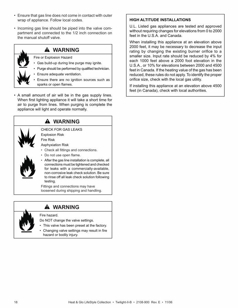
Pressure requirements for appliance are shown in the table below. Minimum pressures must be met when other household gas appliances are operating.
Refer to Reference Section 13 for location of gas line ac-cess in appliance.
Gas Leak Risk• Support control when attaching pipe to prevent
bending gas line.
WARNING
WARNING
WARNING
Pressure Natural Gas PropaneMinimumInlet Pressure
5.0 inchesw.c.
11.0 inchesw.c.
Maximum InletGas Pressure
14.0 inchesw.c.
14.0 inchesw.c.
ManifoldPressure
3.5 inchesw.c.
10.0 inchesw.c.
Heat & Glo LifeStyle Collection • Twilight-II-B • 2108-900 Rev. E • 11/0618
Fire hazard. Do NOT change the valve settings.• This valve has been preset at the factory.• Changing valve settings may result in fi re
hazard or bodily injury.
HIGH ALTITUDE INSTALLATIONSU.L. Listed gas appliances are tested and approved without requiring changes for elevations from 0 to 2000 feet in the U.S.A. and Canada.When installing this appliance at an elevation above 2000 feet, it may be necessary to decrease the input rating by changing the existing burner orifi ce to a smaller size. Input rate should be reduced by 4% for each 1000 feet above a 2000 foot elevation in the U.S.A., or 10% for elevations between 2000 and 4500 feet in Canada. If the heating value of the gas has been reduced, these rules do not apply. To identify the proper orifi ce size, check with the local gas utility.If installing this appliance at an elevation above 4500 feet (in Canada), check with local authorities.
• Ensure that gas line does not come in contact with outer wrap of appliance. Follow local codes.
• Incoming gas line should be piped into the valve com-partment and connected to the 1/2 inch connection on the manual shutoff valve.
CHECK FOR GAS LEAKSExplosion RiskFire RiskAsphyxiation Risk• Check all fi ttings and connections.• Do not use open fl ame.• After the gas line installation is complete, all
connections must be tightened and checked for leaks with a commercially-available, non-corrosive leak check solution. Be sure to rinse off all leak check solution following testing.
Fittings and connections may have loosened during shipping and handling.
Fire or Explosion Hazard• Gas build-up during line purge may ignite.• Purge should be performed by qualifi ed technician.• Ensure adequate ventilation.• Ensure there are no ignition sources such as
sparks or open fl ames.
• A small amount of air will be in the gas supply lines. When fi rst lighting appliance it will take a short time for air to purge from lines. When purging is complete the appliance will light and operate normally.
WARNING
WARNING
WARNING
Heat & Glo LifeStyle Collection • Twilight-II-B • 2108-900 Rev. E • 11/06 19
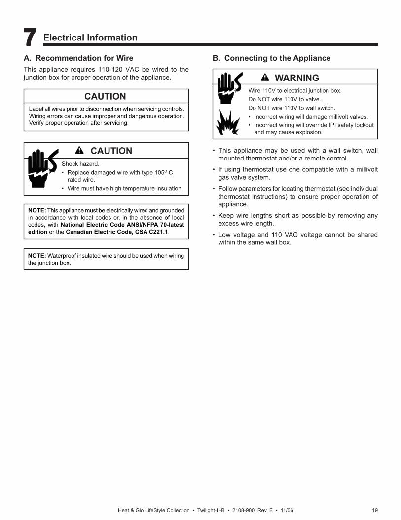
A. Recommendation for WireThis appliance requires 110-120 VAC be wired to the junction box for proper operation of the appliance.
7 7 Electrical Information
NOTE: This appliance must be electrically wired and grounded in accordance with local codes or, in the absence of local codes, with National Electric Code ANSI/NFPA 70-latest edition or the Canadian Electric Code, CSA C221.1.
B. Connecting to the Appliance
Wire 110V to electrical junction box.Do NOT wire 110V to valve.Do NOT wire 110V to wall switch.• Incorrect wiring will damage millivolt valves.• Incorrect wiring will override IPI safety lockout
and may cause explosion.
• This appliance may be used with a wall switch, wall mounted thermostat and/or a remote control.
• If using thermostat use one compatible with a millivolt gas valve system.
• Follow parameters for locating thermostat (see individual thermostat instructions) to ensure proper operation of appliance.
• Keep wire lengths short as possible by removing any excess wire length.
• Low voltage and 110 VAC voltage cannot be shared within the same wall box.
NOTE: Waterproof insulated wire should be used when wiring the junction box.
CAUTIONLabel all wires prior to disconnection when servicing controls. Wiring errors can cause improper and dangerous operation. Verify proper operation after servicing.
Shock hazard.• Replace damaged wire with type 105O C
rated wire.• Wire must have high temperature insulation.
CAUTION
WARNING
Heat & Glo LifeStyle Collection • Twilight-II-B • 2108-900 Rev. E • 11/0620
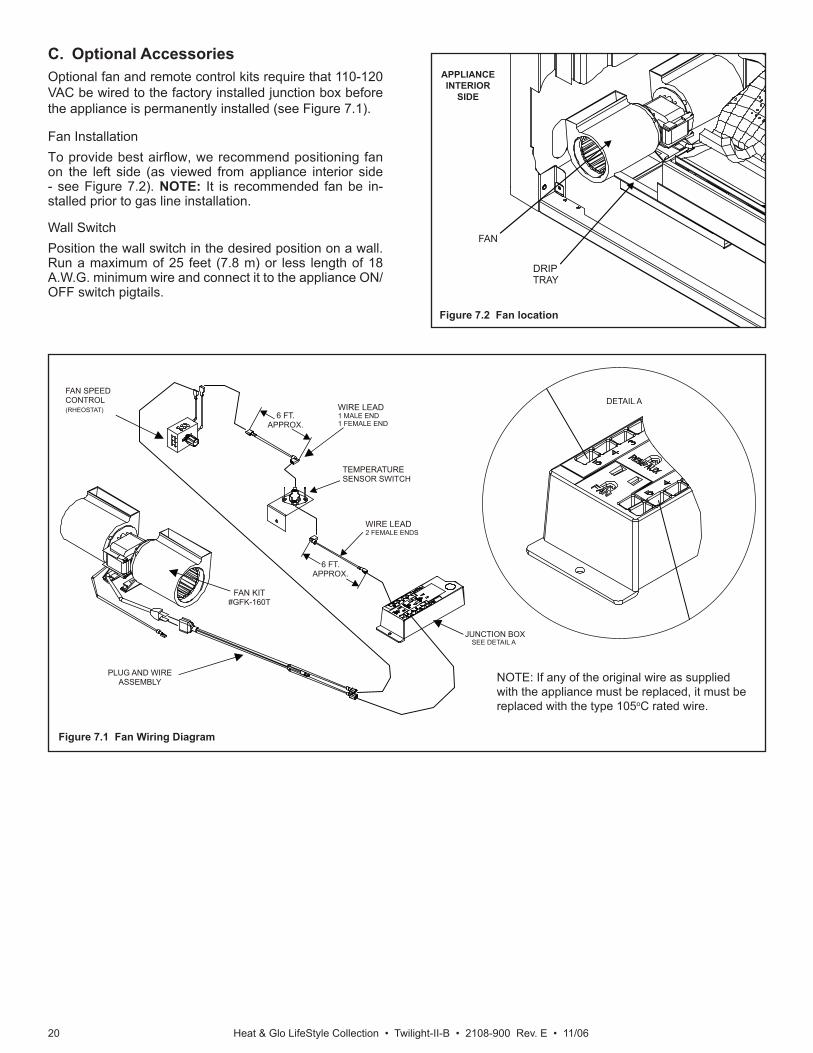
Figure 7.1 Fan Wiring Diagram
C. Optional AccessoriesOptional fan and remote control kits require that 110-120 VAC be wired to the factory installed junction box before the appliance is permanently installed (see Figure 7.1).
Fan InstallationTo provide best airfl ow, we recommend positioning fan on the left side (as viewed from appliance interior side - see Figure 7.2). NOTE: It is recommended fan be in-stalled prior to gas line installation.
Wall Switch Position the wall switch in the desired position on a wall. Run a maximum of 25 feet (7.8 m) or less length of 18 A.W.G. minimum wire and connect it to the appliance ON/OFF switch pigtails.
NOTE: If any of the original wire as supplied with the appliance must be replaced, it must be replaced with the type 105oC rated wire.
Figure 7.2 Fan location
FAN
DRIPTRAY
SEE DETAIL A
WIRE LEAD2 FEMALE ENDS
PLUG AND WIREASSEMBLY
JUNCTION BOX
6 FT.APPROX.
TEMPERATURESENSOR SWITCH
FAN SPEEDCONTROL(RHEOSTAT)
DETAIL AWIRE LEAD1 MALE END1 FEMALE END
6 FT.APPROX.
FAN KIT#GFK-160T
APPLIANCEINTERIOR
SIDE
Heat & Glo LifeStyle Collection • Twilight-II-B • 2108-900 Rev. E • 11/06 21
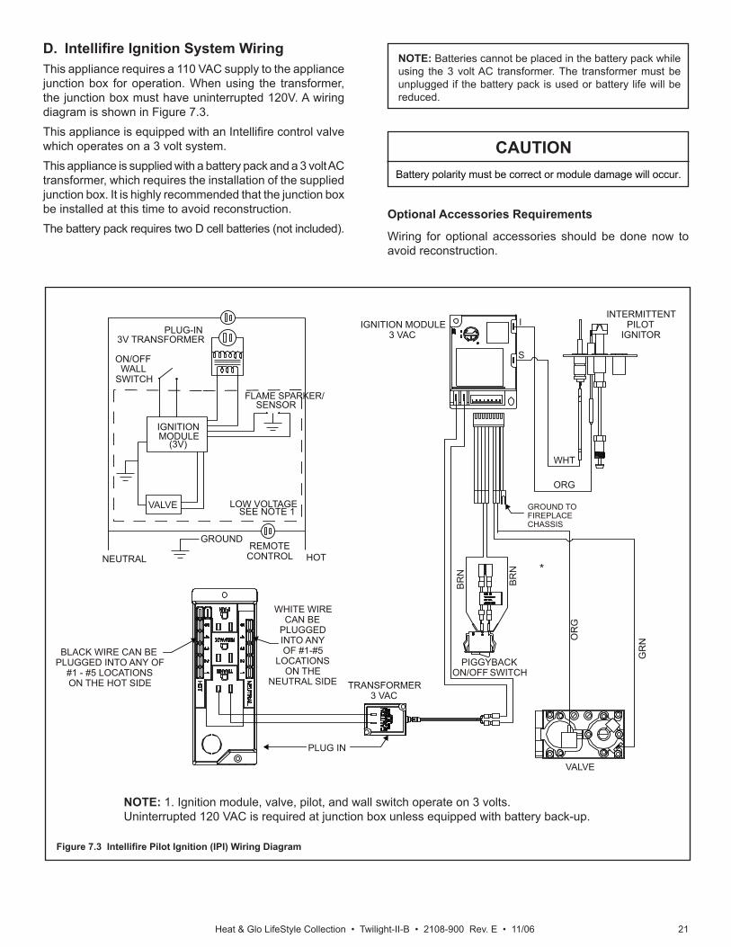
Figure 7.3 Intellifi re Pilot Ignition (IPI) Wiring Diagram
*
NOTE: 1. Ignition module, valve, pilot, and wall switch operate on 3 volts. Uninterrupted 120 VAC is required at junction box unless equipped with battery back-up.
D. Intellifi re Ignition System WiringThis appliance requires a 110 VAC supply to the appliance junction box for operation. When using the transformer, the junction box must have uninterrupted 120V. A wiring diagram is shown in Figure 7.3.This appliance is equipped with an Intellifi re control valve which operates on a 3 volt system. This appliance is supplied with a battery pack and a 3 volt AC transformer, which requires the installation of the supplied junction box. It is highly recommended that the junction box be installed at this time to avoid reconstruction.The battery pack requires two D cell batteries (not included).
CAUTIONBattery polarity must be correct or module damage will occur.
Optional Accessories Requirements
Wiring for optional accessories should be done now to avoid reconstruction.
IGNITION MODULE3 VAC
TRANSFORMER3 VAC
GR
NOR
G
INTERMITTENTPILOT
IGNITOR
IGNITIONMODULE
(3V)
ON/OFFWALL
SWITCH
LOW VOLTAGE
PLUG-IN3V TRANSFORMER
NEUTRAL HOT
GROUND
FLAME SPARKER/SENSOR
REMOTECONTROL
SEE NOTE 1
ORG
WHT
VALVE
PIGGYBACKON/OFF SWITCH
WHITE WIRECAN BE
PLUGGEDINTO ANYOF #1-#5
LOCATIONSON THE
NEUTRAL SIDE
BLACK WIRE CAN BEPLUGGED INTO ANY OF
#1 - #5 LOCATIONSON THE HOT SIDE
BR
N
BR
N
VALVE
PLUG IN
GROUND TOFIREPLACECHASSIS
I
S
NOTE: Batteries cannot be placed in the battery pack while using the 3 volt AC transformer. The transformer must be unplugged if the battery pack is used or battery life will be reduced.
Heat & Glo LifeStyle Collection • Twilight-II-B • 2108-900 Rev. E • 11/0622
6 INCHAPPROX.
WIRE LEAD1 MALE END
1 FEMALE END
TEMPERATURESENSOR SWITCH
WIRE LEAD2 FEMALE ENDS JUNCTION
BOX
6 INCHAPPROX.
FANSPEED CONTROL
(RHEOSTAT)
FAN
PLUG AND WIREASSEMBLY
OPTIONALWALL SWITCH
GREEN WIREINSIDE BOX
14/2WG
COPPER GROUND ATTACHED TO GRN SCREWWITH GRN WIRE
BLKWHT
WHT BLK
HEAT SHIELD
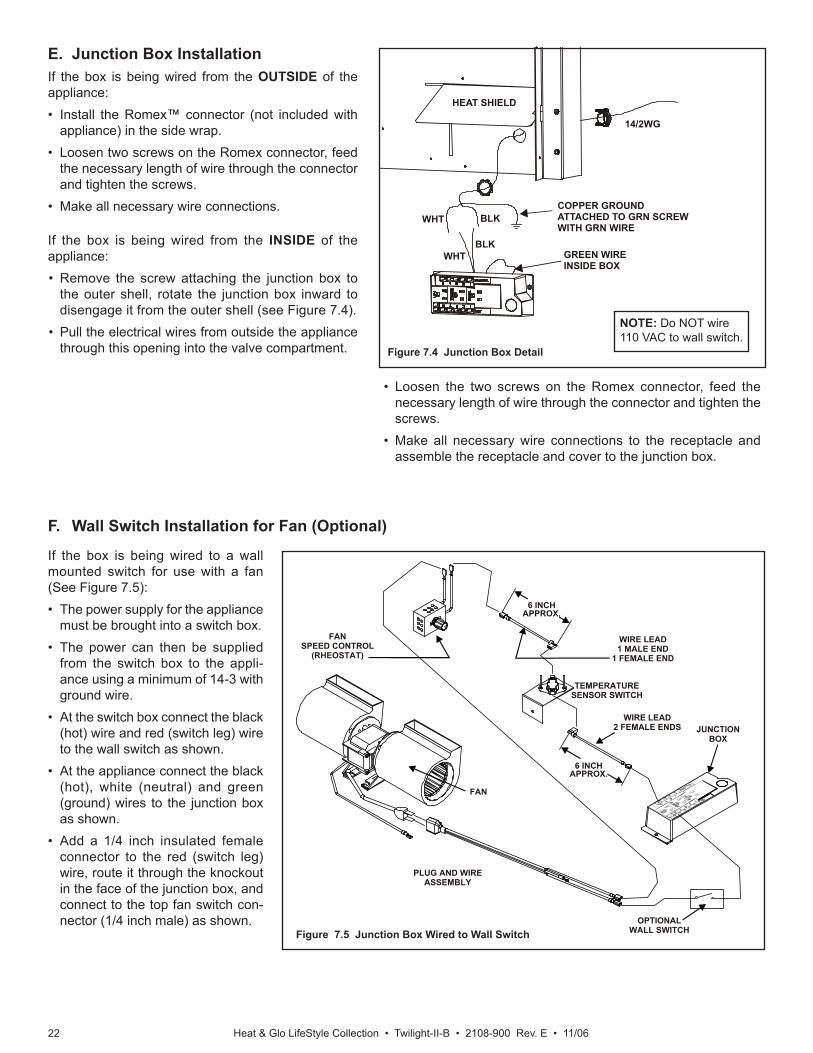
E. Junction Box InstallationIf the box is being wired from the OUTSIDE of the appliance:• Install the Romex™ connector (not included with
appliance) in the side wrap.• Loosen two screws on the Romex connector, feed
the necessary length of wire through the connector and tighten the screws.
• Make all necessary wire connections.
If the box is being wired from the INSIDE of the appliance:• Remove the screw attaching the junction box to
the outer shell, rotate the junction box inward to disengage it from the outer shell (see Figure 7.4).
• Pull the electrical wires from outside the appliance through this opening into the valve compartment.
F. Wall Switch Installation for Fan (Optional)
Figure 7.4 Junction Box Detail
Figure 7.5 Junction Box Wired to Wall Switch
NOTE: Do NOT wire 110 VAC to wall switch.
• Loosen the two screws on the Romex connector, feed the necessary length of wire through the connector and tighten the screws.
• Make all necessary wire connections to the receptacle and assemble the receptacle and cover to the junction box.
If the box is being wired to a wall mounted switch for use with a fan (See Figure 7.5):• The power supply for the appliance
must be brought into a switch box.• The power can then be supplied
from the switch box to the appli-ance using a minimum of 14-3 with ground wire.
• At the switch box connect the black (hot) wire and red (switch leg) wire to the wall switch as shown.
• At the appliance connect the black (hot), white (neutral) and green (ground) wires to the junction box as shown.
• Add a 1/4 inch insulated female connector to the red (switch leg) wire, route it through the knockout in the face of the junction box, and connect to the top fan switch con-nector (1/4 inch male) as shown.
Heat & Glo LifeStyle Collection • Twilight-II-B • 2108-900 Rev. E • 11/06 23
1211
109
87
613-5/8
12-5/8
11-5/8
10-5/8
9-5/8
8-5/8
7-5/8HOOD
NON-COMBUSTIBLE BOARD(SUPPLIED ON APPLIANCE)INDOOR SIDE ONLY
CEILING
35-3/4
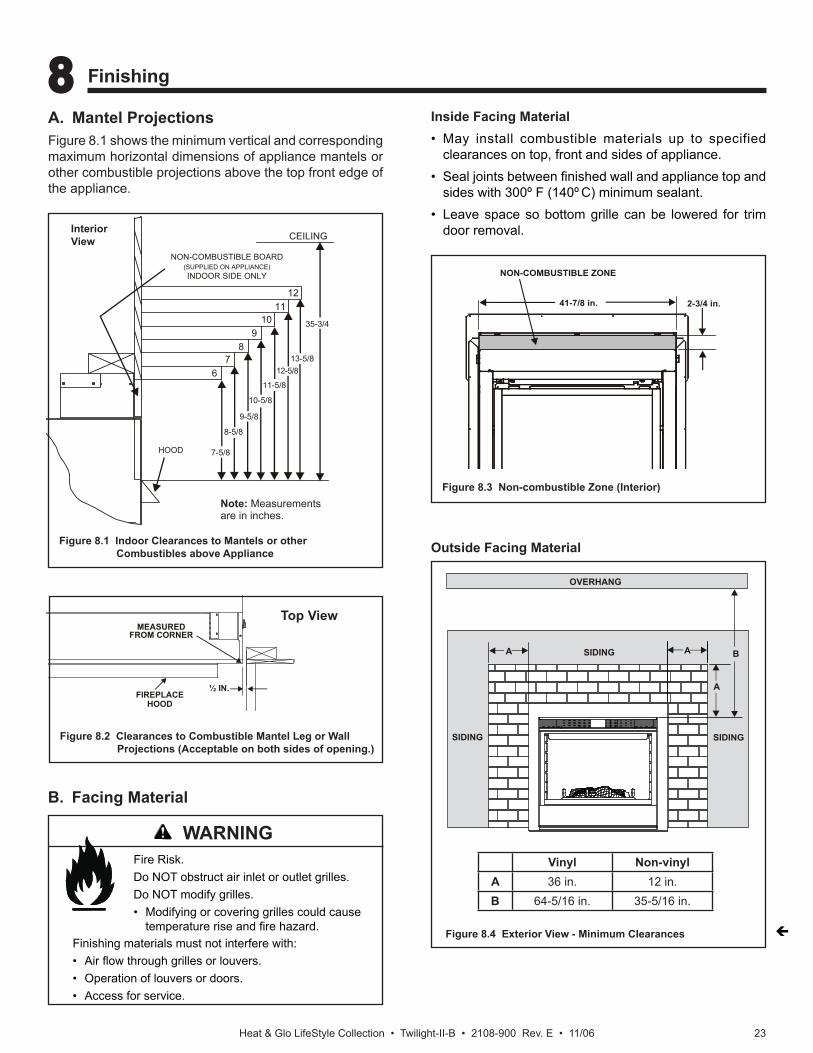
A. Mantel ProjectionsFigure 8.1 shows the minimum vertical and corresponding maximum horizontal dimensions of appliance mantels or other combustible projections above the top front edge of the appliance.
8 8 Finishing
B. Facing Material
Fire Risk.Do NOT obstruct air inlet or outlet grilles.Do NOT modify grilles.• Modifying or covering grilles could cause
temperature rise and fi re hazard.Finishing materials must not interfere with:• Air fl ow through grilles or louvers.• Operation of louvers or doors.• Access for service.
Inside Facing Material• May install combustible materials up to specified
clearances on top, front and sides of appliance.• Seal joints between fi nished wall and appliance top and
sides with 300º F (140º C) minimum sealant.• Leave space so bottom grille can be lowered for trim
door removal.
41-7/8 in. 2-3/4 in.
NON-COMBUSTIBLE ZONE
Figure 8.1 Indoor Clearances to Mantels or other Combustibles above Appliance
Note: Measurements are in inches.
Interior View
Figure 8.3 Non-combustible Zone (Interior)
Outside Facing Material
Figure 8.2 Clearances to Combustible Mantel Leg or Wall Projections (Acceptable on both sides of opening.)
Top View
WARNING
MEASUREDFROM CORNER
FIREPLACEHOOD
½ IN.
Figure 8.4 Exterior View - Minimum Clearances
Vinyl Non-vinylA 36 in. 12 in.B 64-5/16 in. 35-5/16 in.
OVERHANG
AA
A
B
SIDING SIDING
SIDING
Heat & Glo LifeStyle Collection • Twilight-II-B • 2108-900 Rev. E • 11/0624
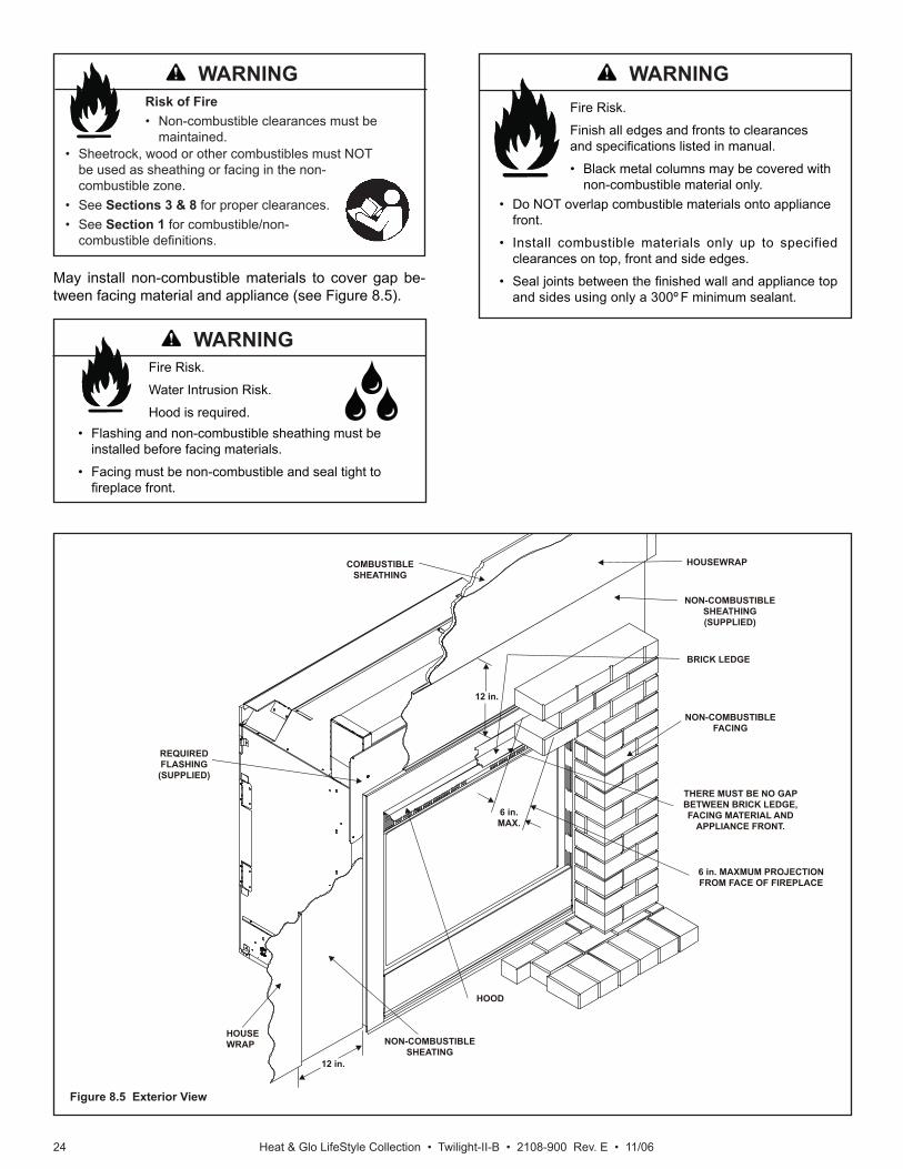
Figure 8.5 Exterior View
Fire Risk.
Finish all edges and fronts to clearances and specifi cations listed in manual.
• Black metal columns may be covered with non-combustible material only.
• Do NOT overlap combustible materials onto appliance front.
• Install combustible materials only up to specified clearances on top, front and side edges.
• Seal joints between the fi nished wall and appliance top and sides using only a 300º F minimum sealant.
May install non-combustible materials to cover gap be-tween facing material and appliance (see Figure 8.5).
Fire Risk.
Water Intrusion Risk.
Hood is required.• Flashing and non-combustible sheathing must be
installed before facing materials.
• Facing must be non-combustible and seal tight to fi replace front.
Risk of Fire • Non-combustible clearances must be
maintained.• Sheetrock, wood or other combustibles must NOT
be used as sheathing or facing in the non-combustible zone.
• See Sections 3 & 8 for proper clearances.• See Section 1 for combustible/non-
combustible defi nitions.
12 in.
12 in.
HOOD
NON-COMBUSTIBLESHEATING
6 in.MAX.
NON-COMBUSTIBLEFACING
THERE MUST BE NO GAPBETWEEN BRICK LEDGE,FACING MATERIAL AND
APPLIANCE FRONT.
6 in. MAXMUM PROJECTIONFROM FACE OF FIREPLACE
BRICK LEDGE
NON-COMBUSTIBLESHEATHING(SUPPLIED)
COMBUSTIBLESHEATHING
HOUSEWRAP
REQUIREDFLASHING(SUPPLIED)
HOUSEWRAP
WARNINGWARNING
WARNING
Heat & Glo LifeStyle Collection • Twilight-II-B • 2108-900 Rev. E • 11/06 25
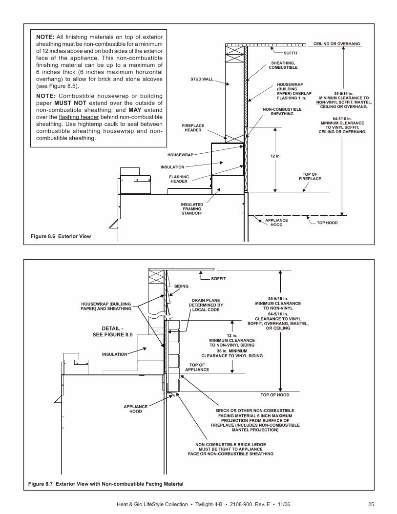
Figure 8.7 Exterior View with Non-combustible Facing Material
APPLIANCEHOOD
TOP OFAPPLIANCE
SOFFIT
SIDING
HOUSEWRAP (BUILDINGPAPER) AND SHEATHING
35-5/16 in.MINIMUM CLEARANCE
TO NON-VINYL64-5/16 in.
CLEARANCE TO VINYLSOFFIT, OVERHANG, MANTEL,
OR CEILING
12 in.MINIMUM CLEARANCETO NON-VINYL SIDING
36 in. MINIMUMCLEARANCE TO VINYL SIDING
DRAIN PLANEDETERMINED BY
LOCAL CODE
BRICK OR OTHER NON-COMBUSTIBLEFACING MATERIAL 6 INCH MAXIMUM
PROJECTION FROM SURFACE OFFIREPLACE (INCLUDES NON-COMBUSTIBLE
MANTEL PROJECTION)
NON-COMBUSTIBLE BRICK LEDGEMUST BE TIGHT TO APPLIANCE
FACE OR NON-COMBUSTIBLE SHEATHING
TOP OF HOOD
INSULATION
Figure 8.6 Exterior View
DETAIL - SEE FIGURE 8.5
NOTE: All fi nishing materials on top of exterior sheathing must be non-combustible for a minimum of 12 inches above and on both sides of the exterior face of the appliance. This non-combustible fi nishing material can be up to a maximum of 6 inches thick (6 inches maximum horizontal overhang) to allow for brick and stone alcoves (see Figure 8.5).
NOTE: Combustible housewrap or building paper MUST NOT extend over the outside of non-combustible sheathing, and MAY extend over the fl ashing header behind non-combustible sheathing. Use hightemp caulk to seal between combustible sheathing housewrap and non-combustible sheathing.
APPLIANCEHOOD TOP HOOD
TOP OFFIREPLACE
12 in.
CEILING OR OVERHANG
64-5/16 in.MINIMUM CLEARANCE
TO VINYL SOFFIT,CEILING OR OVERHANG.
35-5/16 in.MINIMUM CLEARANCE TO
NON-VINYL SOFFIT, MANTEL,CEILING OR OVERHANG.
STUD WALL
SOFFIT
HOUSEWRAP
INSULATION
HOUSEWRAP(BUILDINGPAPER) OVERLAPFLASHING 1 in.
SHEATHING,COMBUSTIBLE
FIREPLACEHEADER
INSULATED FRAMING
STANDOFF
NON-COMBUSTIBLESHEATHING
FLASHINGHEADER
Heat & Glo LifeStyle Collection • Twilight-II-B • 2108-900 Rev. E • 11/0626
9 9 Appliance Setup
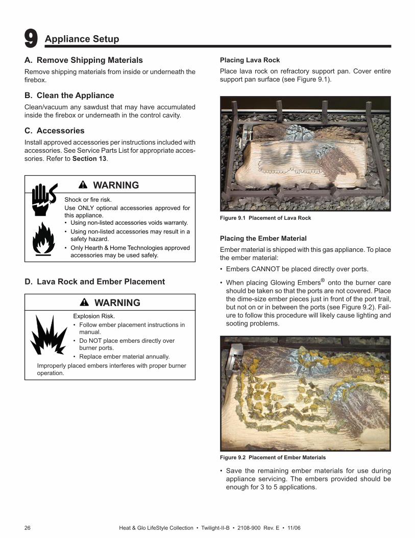
A. Remove Shipping MaterialsRemove shipping materials from inside or underneath the fi rebox.
B. Clean the ApplianceClean/vacuum any sawdust that may have accumulated inside the fi rebox or underneath in the control cavity.
C. AccessoriesInstall approved accessories per instructions included with accessories. See Service Parts List for appropriate acces-sories. Refer to Section 13.
Shock or fi re risk.Use ONLY optional accessories approved for this appliance.• Using non-listed accessories voids warranty.• Using non-listed accessories may result in a
safety hazard.• Only Hearth & Home Technologies approved
accessories may be used safely.
D. Lava Rock and Ember Placement
Explosion Risk.• Follow ember placement instructions in
manual.• Do NOT place embers directly over
burner ports.• Replace ember material annually.
Improperly placed embers interferes with proper burner operation.
Placing the Ember MaterialEmber material is shipped with this gas appliance. To place the ember material:• Embers CANNOT be placed directly over ports.
• When placing Glowing Embers® onto the burner care should be taken so that the ports are not covered. Place the dime-size ember pieces just in front of the port trail, but not on or in between the ports (see Figure 9.2). Fail-ure to follow this procedure will likely cause lighting and sooting problems.
Figure 9.2 Placement of Ember Materials
• Save the remaining ember materials for use during appliance servicing. The embers provided should be enough for 3 to 5 applications.
Placing Lava RockPlace lava rock on refractory support pan. Cover entire support pan surface (see Figure 9.1).
Figure 9.1 Placement of Lava Rock
WARNING
WARNING
Heat & Glo LifeStyle Collection • Twilight-II-B • 2108-900 Rev. E • 11/06 27
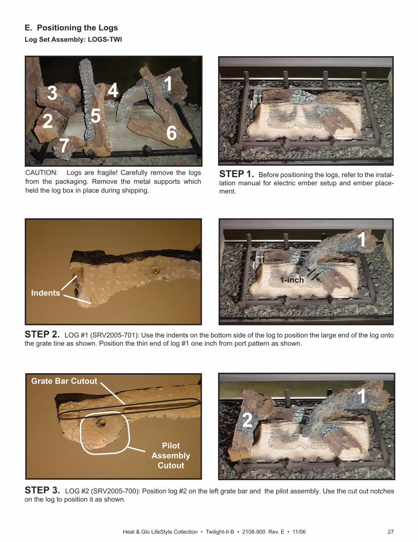
E. Positioning the Logs Log Set Assembly: LOGS-TWI
1
2
CAUTION: Logs are fragile! Carefully remove the logs from the packaging. Remove the metal supports which held the log box in place during shipping.
STEP 2. LOG #1 (SRV2005-701): Use the indents on the bottom side of the log to position the large end of the log onto the grate tine as shown. Position the thin end of log #1 one inch from port pattern as shown.
STEP 3. LOG #2 (SRV2005-700): Position log #2 on the left grate bar and the pilot assembly. Use the cut out notches on the log to position it as shown.
STEP 1. Before positioning the logs, refer to the instal-lation manual for electric ember setup and ember place-ment.
1
2
45
67
3
Indents
Pilot Assembly
Cutout
Grate Bar Cutout
1-inch
1
Heat & Glo LifeStyle Collection • Twilight-II-B • 2108-900 Rev. E • 11/0628
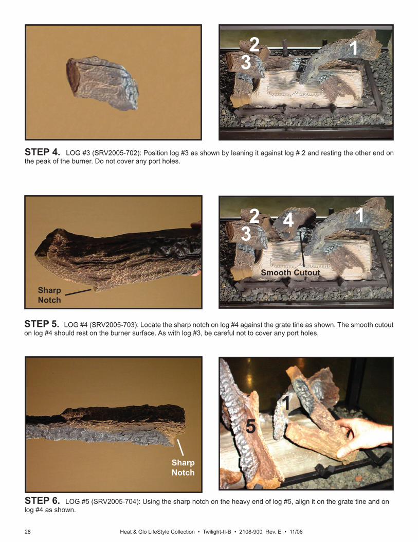
STEP 4. LOG #3 (SRV2005-702): Position log #3 as shown by leaning it against log # 2 and resting the other end on the peak of the burner. Do not cover any port holes.
STEP 5. LOG #4 (SRV2005-703): Locate the sharp notch on log #4 against the grate tine as shown. The smooth cutout on log #4 should rest on the burner surface. As with log #3, be careful not to cover any port holes.
STEP 6. LOG #5 (SRV2005-704): Using the sharp notch on the heavy end of log #5, align it on the grate tine and on log #4 as shown.
3
4
5
Sharp Notch
Sharp Notch
Smooth Cutout
2 1
32 1
1
Heat & Glo LifeStyle Collection • Twilight-II-B • 2108-900 Rev. E • 11/06 29
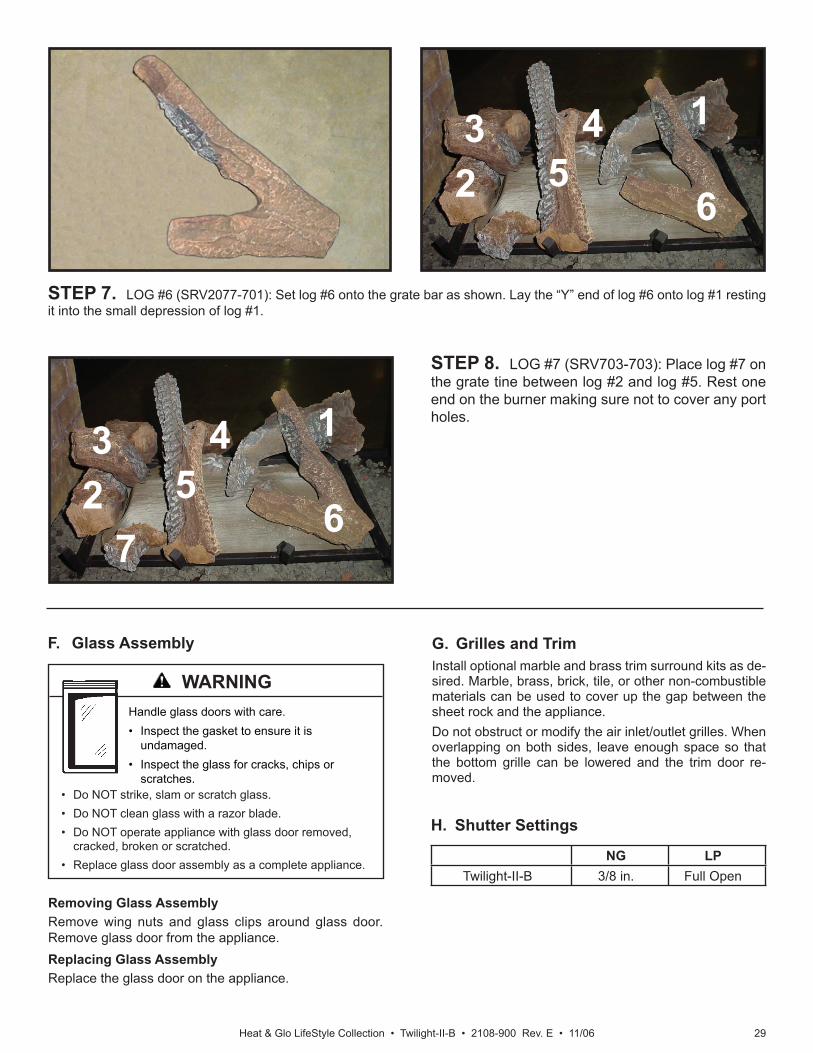
STEP 8. LOG #7 (SRV703-703): Place log #7 on the grate tine between log #2 and log #5. Rest one end on the burner making sure not to cover any port holes.
STEP 7. LOG #6 (SRV2077-701): Set log #6 onto the grate bar as shown. Lay the “Y” end of log #6 onto log #1 resting it into the small depression of log #1.
F. Glass Assembly
Removing Glass AssemblyRemove wing nuts and glass clips around glass door. Remove glass door from the appliance.Replacing Glass AssemblyReplace the glass door on the appliance.
Handle glass doors with care.• Inspect the gasket to ensure it is
undamaged.• Inspect the glass for cracks, chips or
scratches.• Do NOT strike, slam or scratch glass.• Do NOT clean glass with a razor blade.• Do NOT operate appliance with glass door removed,
cracked, broken or scratched.• Replace glass door assembly as a complete appliance.
G. Grilles and TrimInstall optional marble and brass trim surround kits as de-sired. Marble, brass, brick, tile, or other non-combustible materials can be used to cover up the gap between the sheet rock and the appliance.Do not obstruct or modify the air inlet/outlet grilles. When overlapping on both sides, leave enough space so that the bottom grille can be lowered and the trim door re-moved.
H. Shutter Settings
NG LPTwilight-II-B 3/8 in. Full Open
1
24
56
3
1
24
56
3
7
WARNING
Heat & Glo LifeStyle Collection • Twilight-II-B • 2108-900 Rev. E • 11/0630
A. Before Lighting ApplianceThis appliance has an Intellifi re ignition system.
10 10 Operating Instructions
CAUTIONIf installing Intellifi re ignition battery backup:• Do not install batteries if the backup mode may not be
used for extended time.• Batteries may leak.• Install batteries only when needed for power outage.
Before operating this appliance have a qualifi ed tech-nician:• Remove all shipping materials from inside and/or un-
derneath the fi rebox.• Review proper placement of logs, rockwool, lava rock,
and vermiculite.• Check the wiring.• Check the air shutter adjustment.• Ensure that there are no gas leaks.• Ensure that the glass is sealed and in the proper posi-
tion.• Ensure that the fl ow of combustion and ventilation air
is not obstructed (front grilles and vent caps).
HOT! DO NOT TOUCH. SEVERE BURNS MAY RESULT.CLOTHING IGNITION MAY RESULT.Glass and other surfaces are hot during operation and cool down.• Keep children away.
Glass door must be in place when appliance is operating.Risk of:• Combustion Fumes• FireDo NOT operate appliance with glass door removed.
Improper installation, adjustment, alteration, service or maintenance can cause injury or property damage. Refer to the owner’s information manual provided with this appliance. For assistance or additional information consult a qualifi ed installer, service agency or the gas supplier.
Do NOT use this appliance if any part has been under water. Immediately call a qualifi ed service technician to inspect the appliance and to replace any part of the control system and any gas control which has been under water.
• Open viewing glass for servicing only.• Glass door MUST be in place and sealed before
operating appliance.• Only use glass door certifi ed for use with appliance.• Glass replacement should be done by qualifi ed
technician.
A protective barrier is provided on the interior door to prevent direct contact with the fi xed glass panel. Do NOT operate the appliance without that protective barrier.
Contact your dealer or Hearth & Home Technologies if help is needed to properly install a protective barrier.
• CAREFULLY SUPERVISE children in same room as appliance.
• Alert children and adults to hazards of high temperatures.
• Do NOT operate with protective barrier open or removed.
• Keep clothing, furniture, draperies and other combustibles away.
WARNING
WARNING
WARNING
WARNING
Heat & Glo LifeStyle Collection • Twilight-II-B • 2108-900 Rev. E • 11/06 31
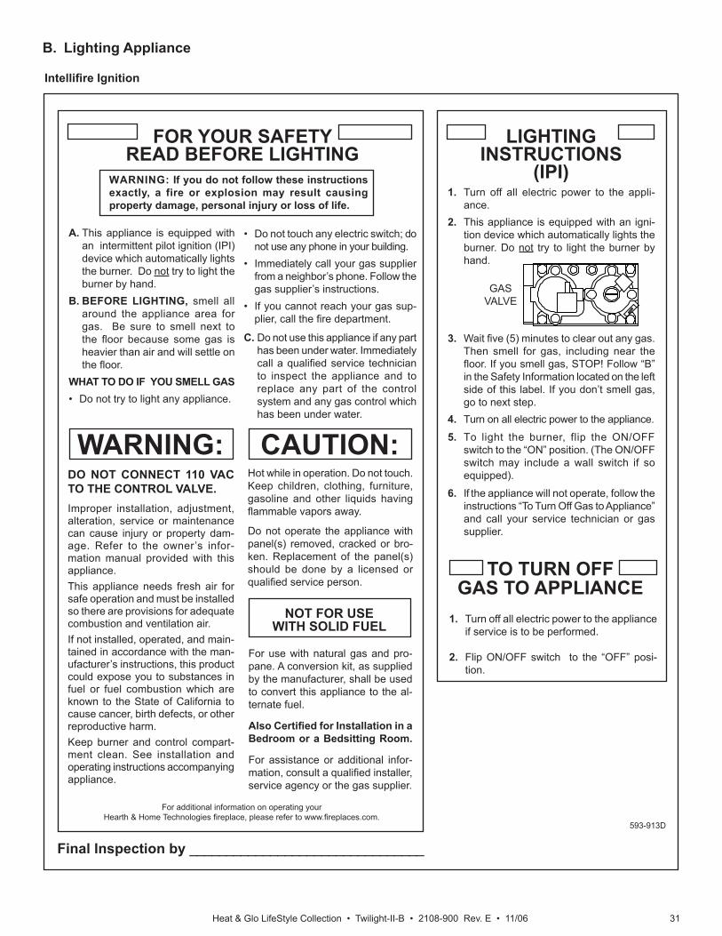
B. Lighting Appliance
Intellifi re Ignition
Final Inspection by ________________________________
1. Turn off all electric power to the appli-ance.
2. This appliance is equipped with an igni-tion device which automatically lights the burner. Do not try to light the burner by hand.
3. Wait fi ve (5) minutes to clear out any gas. Then smell for gas, including near the fl oor. If you smell gas, STOP! Follow “B” in the Safety Information located on the left side of this label. If you don’t smell gas, go to next step.
4. Turn on all electric power to the appliance.
5. To light the burner, flip the ON/OFF switch to the “ON” position. (The ON/OFF switch may include a wall switch if so equipped).
6. If the appliance will not operate, follow the instructions “To Turn Off Gas to Appliance” and call your service technician or gas supplier.
LIGHTINGINSTRUCTIONS
(IPI)
TO TURN OFFGAS TO APPLIANCE
1. Turn off all electric power to the appliance if service is to be performed.
2. Flip ON/OFF switch to the “OFF” posi-tion.
FOR YOUR SAFETYREAD BEFORE LIGHTING
WARNING: If you do not follow these instructions exactly, a fire or explosion may result causing property damage, personal injury or loss of life.
A. This appliance is equipped with an intermittent pilot ignition (IPI) device which automatically lights the burner. Do not try to light the burner by hand.
B. BEFORE LIGHTING, smell all around the appliance area for gas. Be sure to smell next to the fl oor because some gas is heavier than air and will settle on the fl oor.
WHAT TO DO IF YOU SMELL GAS• Do not try to light any appliance.
DO NOT CONNECT 110 VAC TO THE CONTROL VALVE.Improper installation, adjustment, alteration, service or maintenance can cause injury or property dam-age. Refer to the owner’s infor-mation manual provided with this appliance.This appliance needs fresh air for safe operation and must be installed so there are provisions for adequate combustion and ventilation air.If not installed, operated, and main-tained in accordance with the man-ufacturer’s instructions, this product could expose you to substances in fuel or fuel combustion which are known to the State of California to cause cancer, birth defects, or other reproductive harm.Keep burner and control compart-ment clean. See installation and operating instructions accompanying appliance.
CAUTION:Hot while in operation. Do not touch. Keep children, clothing, furniture, gasoline and other liquids having fl ammable vapors away.
Do not operate the appliance with panel(s) removed, cracked or bro-ken. Replacement of the panel(s) should be done by a licensed or qualifi ed service person.
• Do not touch any electric switch; do not use any phone in your building.
• Immediately call your gas supplier from a neighbor’s phone. Follow the gas supplier’s instructions.
• If you cannot reach your gas sup-plier, call the fi re department.
C. Do not use this appliance if any part has been under water. Immediately call a qualifi ed service technician to inspect the appliance and to replace any part of the control system and any gas control which has been under water.
NOT FOR USE WITH SOLID FUEL
For use with natural gas and pro-pane. A conversion kit, as supplied by the manufacturer, shall be used to convert this appliance to the al-ternate fuel.
Also Certifi ed for Installation in a Bedroom or a Bedsitting Room.
For assistance or additional infor-mation, consult a qualifi ed installer, service agency or the gas supplier.
WARNING:
593-913D
GASVALVE
For additional information on operating your Hearth & Home Technologies fi replace, please refer to www.fi replaces.com.
Heat & Glo LifeStyle Collection • Twilight-II-B • 2108-900 Rev. E • 11/0632
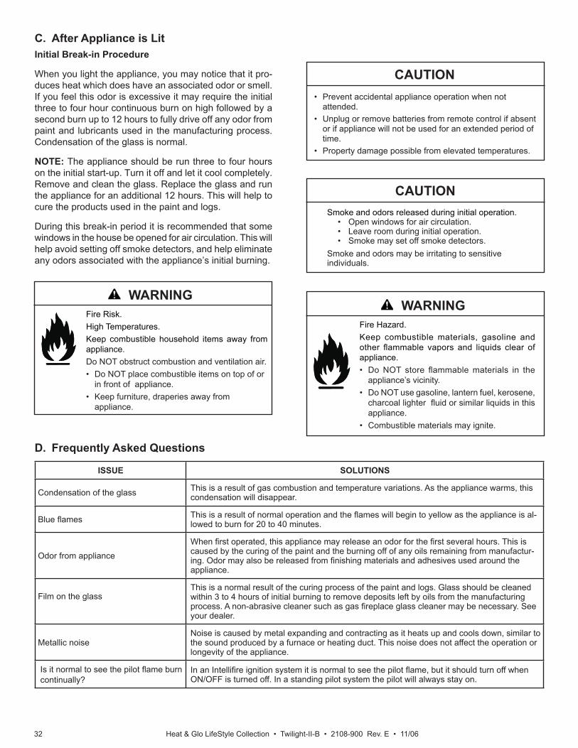
C. After Appliance is LitInitial Break-in Procedure
When you light the appliance, you may notice that it pro-duces heat which does have an associated odor or smell. If you feel this odor is excessive it may require the initial three to four hour continuous burn on high followed by a second burn up to 12 hours to fully drive off any odor from paint and lubricants used in the manufacturing process. Condensation of the glass is normal.
NOTE: The appliance should be run three to four hours on the initial start-up. Turn it off and let it cool completely. Remove and clean the glass. Replace the glass and run the appliance for an additional 12 hours. This will help to cure the products used in the paint and logs.
During this break-in period it is recommended that some windows in the house be opened for air circulation. This will help avoid setting off smoke detectors, and help eliminate any odors associated with the appliance’s initial burning.
D. Frequently Asked Questions
Fire Risk.High Temperatures.Keep combustible household items away from appliance.Do NOT obstruct combustion and ventilation air.• Do NOT place combustible items on top of or
in front of appliance. • Keep furniture, draperies away from
appliance.
Smoke and odors released during initial operation.• Open windows for air circulation.• Leave room during initial operation.• Smoke may set off smoke detectors.
Smoke and odors may be irritating to sensitive individuals.
CAUTION
• Prevent accidental appliance operation when not attended.
• Unplug or remove batteries from remote control if absent or if appliance will not be used for an extended period of time.
• Property damage possible from elevated temperatures.
CAUTION
Fire Hazard.Keep combustible materials, gasoline and other fl ammable vapors and liquids clear of appliance.• Do NOT store fl ammable materials in the
appliance’s vicinity.• Do NOT use gasoline, lantern fuel, kerosene,
charcoal lighter fl uid or similar liquids in this appliance.
• Combustible materials may ignite.
ISSUE SOLUTIONS
Condensation of the glass This is a result of gas combustion and temperature variations. As the appliance warms, this condensation will disappear.
Blue fl ames This is a result of normal operation and the fl ames will begin to yellow as the appliance is al-lowed to burn for 20 to 40 minutes.
Odor from appliance
When fi rst operated, this appliance may release an odor for the fi rst several hours. This is caused by the curing of the paint and the burning off of any oils remaining from manufactur-ing. Odor may also be released from fi nishing materials and adhesives used around the appliance.
Film on the glassThis is a normal result of the curing process of the paint and logs. Glass should be cleaned within 3 to 4 hours of initial burning to remove deposits left by oils from the manufacturing process. A non-abrasive cleaner such as gas fi replace glass cleaner may be necessary. See your dealer.
Metallic noiseNoise is caused by metal expanding and contracting as it heats up and cools down, similar to the sound produced by a furnace or heating duct. This noise does not affect the operation or longevity of the appliance.
Is it normal to see the pilot fl ame burn continually?
In an Intellifi re ignition system it is normal to see the pilot fl ame, but it should turn off when ON/OFF is turned off. In a standing pilot system the pilot will always stay on.
WARNINGWARNING
Heat & Glo LifeStyle Collection • Twilight-II-B • 2108-900 Rev. E • 11/06 33
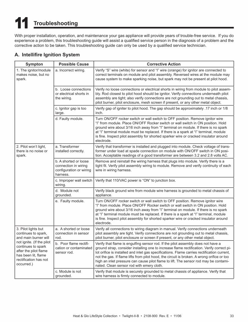
11 11 Troubleshooting
With proper installation, operation, and maintenance your gas appliance will provide years of trouble-free service. If you do experience a problem, this troubleshooting guide will assist a qualifi ed service person in the diagnosis of a problem and the corrective action to be taken. This troubleshooting guide can only be used by a qualifi ed service technician.
A. Intellifi re Ignition System
Sympton Possible Cause Corrective Action1. The ignitor/module makes noise, but no spark.
a. Incorrect wiring. Verify “S” wire (white) for sensor and “I” wire (orange) for ignitor are connected to correct terminals on module and pilot assembly. Reversed wires at the module may cause system to make sparking noise, but spark may not be present at pilot hood.
b. Loose connections or electrical shorts in the wiring.
Verify no loose connections or electrical shorts in wiring from module to pilot assem-bly. Rod closest to pilot hood should be ignitor. Verify connections underneath pilot assembly are tight; also verify connections are not grounding out to metal chassis, pilot burner, pilot enclosure, mesh screen if present, or any other metal object.
c. Ignitor gap is too large.
Verify gap of igniter to pilot hood. The gap should be approximately .17 inch or 1/8 inch.
d. Faulty module. Turn ON/OFF rocker switch or wall switch to OFF position. Remove ignitor wire “I” from module. Place ON/OFF Rocker switch or wall switch in ON position. Hold ground wire about 3/16 inch away from “I” terminal on module. If there is no spark at “I” terminal module must be replaced. If there is a spark at “I” terminal, module is fi ne. Inspect pilot assembly for shorted sparker wire or cracked insulator around electrode.
2. Pilot won’t light, there is no noise or spark.
a. Transformer installed correctly.
Verify that transformer is installed and plugged into module. Check voltage of trans-former under load at spade connection on module with ON/OFF switch in ON posi-tion. Acceptable readings of a good transformer are between 3.2 and 2.8 volts AC.
b. A shorted or loose connection in wiring confi guration or wiring harness.
Remove and reinstall the wiring harness that plugs into module. Verify there is a tight fi t. Verify pilot assembly wiring to module. Remove and verify continuity of each wire in wiring harness.
c. Improper wall switch wiring.
Verify that 110/VAC power is “ON” to junction box.
d. Module not grounded.
Verify black ground wire from module wire harness is grounded to metal chassis of appliance.
e. Faulty module. Turn ON/OFF rocker switch or wall switch to OFF position. Remove ignitor wire “I” from module. Place ON/OFF Rocker switch or wall switch in ON position. Hold ground wire about 3/16 inch away from “I” terminal on module. If there is no spark at “I” terminal module must be replaced. If there is a spark at “I” terminal, module is fi ne. Inspect pilot assembly for shorted sparker wire or cracked insulator around electrode.
3. Pilot lights but continues to spark, and main burner will not ignite. (If the pilot continues to spark after the pilot fl ame has been lit, fl ame rectifi cation has not occurred.)
a. A shorted or loose connection in sensor rod.
Verify all connections to wiring diagram in manual. Verify connections underneath pilot assembly are tight. Verify connections are not grounding out to metal chassis, pilot burner, pilot enclosure or screen if present, or any other metal object.
b. Poor fl ame rectifi -cation or contaminated sensor rod.
Verify that fl ame is engulfi ng sensor rod. If the pilot assembly does not have a ground strap, consider installing one to increase fl ame rectifi cation. Verify correct pi-lot orifi ce is installed and inlet gas specifi cations. Flame carries rectifi cation current, not the gas. If fl ame lifts from pilot hood, the circuit is broken. A wrong orifi ce or too high an inlet pressure can cause pilot fl ame to lift. The sensor rod may be contami-nated. Clean sensor rod with emery cloth.
c. Module is not grounded.
Verify that module is securely grounded to metal chassis of appliance. Verify that wire harness is fi rmly connected to module.
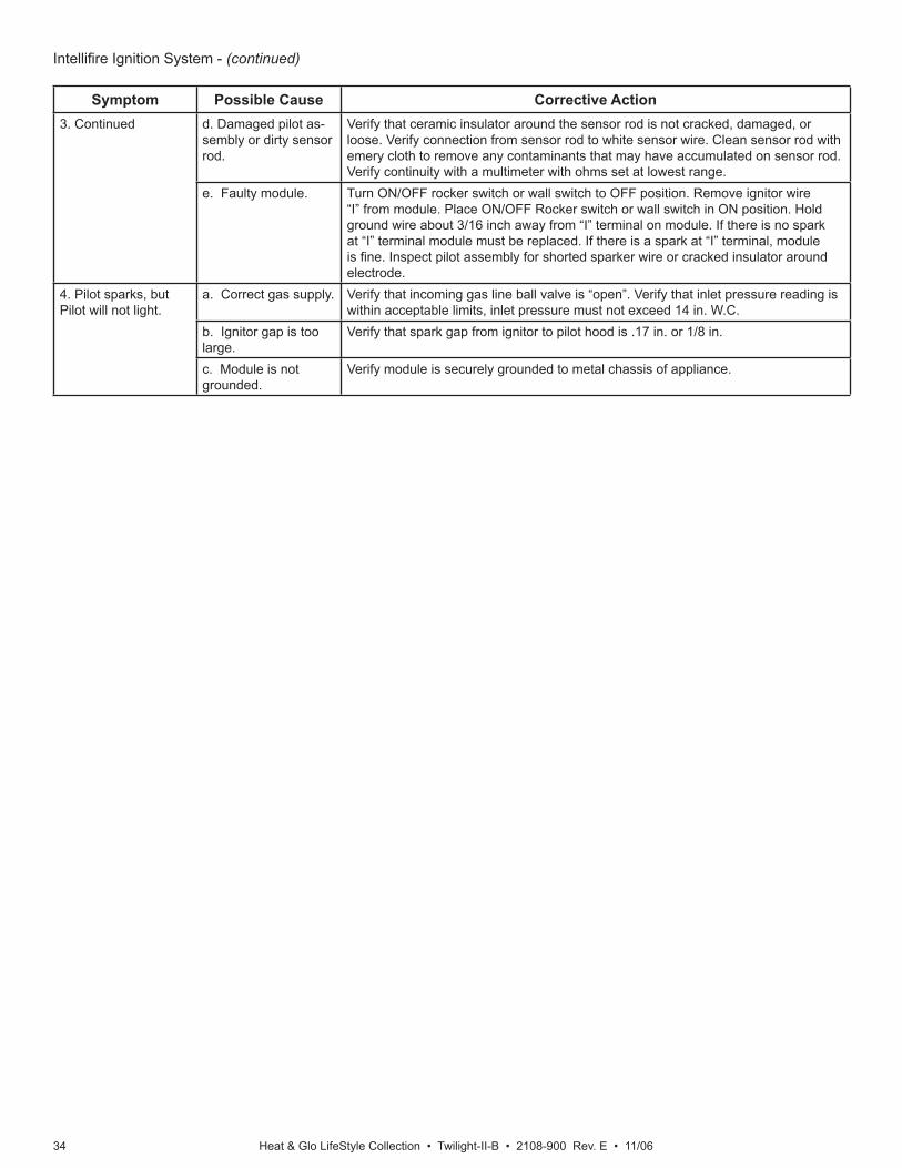
Heat & Glo LifeStyle Collection • Twilight-II-B • 2108-900 Rev. E • 11/0634
Intellifi re Ignition System - (continued)
Symptom Possible Cause Corrective Action3. Continued d. Damaged pilot as-
sembly or dirty sensor rod.
Verify that ceramic insulator around the sensor rod is not cracked, damaged, or loose. Verify connection from sensor rod to white sensor wire. Clean sensor rod with emery cloth to remove any contaminants that may have accumulated on sensor rod. Verify continuity with a multimeter with ohms set at lowest range.
e. Faulty module. Turn ON/OFF rocker switch or wall switch to OFF position. Remove ignitor wire “I” from module. Place ON/OFF Rocker switch or wall switch in ON position. Hold ground wire about 3/16 inch away from “I” terminal on module. If there is no spark at “I” terminal module must be replaced. If there is a spark at “I” terminal, module is fi ne. Inspect pilot assembly for shorted sparker wire or cracked insulator around electrode.
4. Pilot sparks, but Pilot will not light.
a. Correct gas supply. Verify that incoming gas line ball valve is “open”. Verify that inlet pressure reading is within acceptable limits, inlet pressure must not exceed 14 in. W.C.
b. Ignitor gap is too large.
Verify that spark gap from ignitor to pilot hood is .17 in. or 1/8 in.
c. Module is not grounded.
Verify module is securely grounded to metal chassis of appliance.
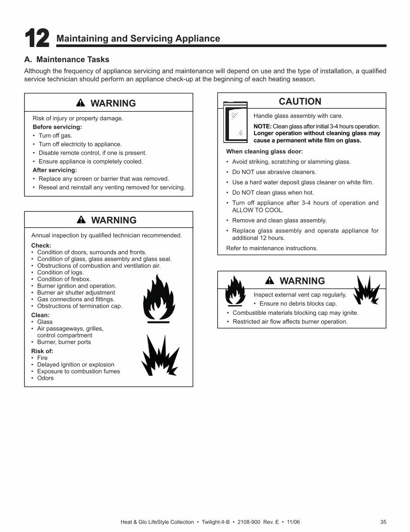
Heat & Glo LifeStyle Collection • Twilight-II-B • 2108-900 Rev. E • 11/06 35
A. Maintenance TasksAlthough the frequency of appliance servicing and maintenance will depend on use and the type of installation, a qualifi ed service technician should perform an appliance check-up at the beginning of each heating season.
Annual inspection by qualifi ed technician recommended.
Check:• Condition of doors, surrounds and fronts.• Condition of glass, glass assembly and glass seal.• Obstructions of combustion and ventilation air.• Condition of logs.• Condition of fi rebox.• Burner ignition and operation.• Burner air shutter adjustment• Gas connections and fi ttings.• Obstructions of termination cap.Clean:• Glass• Air passageways, grilles, control compartment• Burner, burner ports Risk of:• Fire• Delayed ignition or explosion• Exposure to combustion fumes• Odors
Handle glass assembly with care.
NOTE: Clean glass after initial 3-4 hours operation. Longer operation without cleaning glass may cause a permanent white fi lm on glass.
CAUTION
When cleaning glass door:• Avoid striking, scratching or slamming glass.
• Do NOT use abrasive cleaners.
• Use a hard water deposit glass cleaner on white fi lm.
• Do NOT clean glass when hot.
• Turn off appliance after 3-4 hours of operation and ALLOW TO COOL.
• Remove and clean glass assembly.
• Replace glass assembly and operate appliance for additional 12 hours.
Refer to maintenance instructions.
Risk of injury or property damage.Before servicing:• Turn off gas.• Turn off electricity to appliance.• Disable remote control, if one is present.• Ensure appliance is completely cooled.After servicing:• Replace any screen or barrier that was removed.• Reseal and reinstall any venting removed for servicing.
Inspect external vent cap regularly.• Ensure no debris blocks cap.
WARNING
WARNING
WARNING
• Combustible materials blocking cap may ignite.• Restricted air fl ow affects burner operation.
12 12 Maintaining and Servicing Appliance
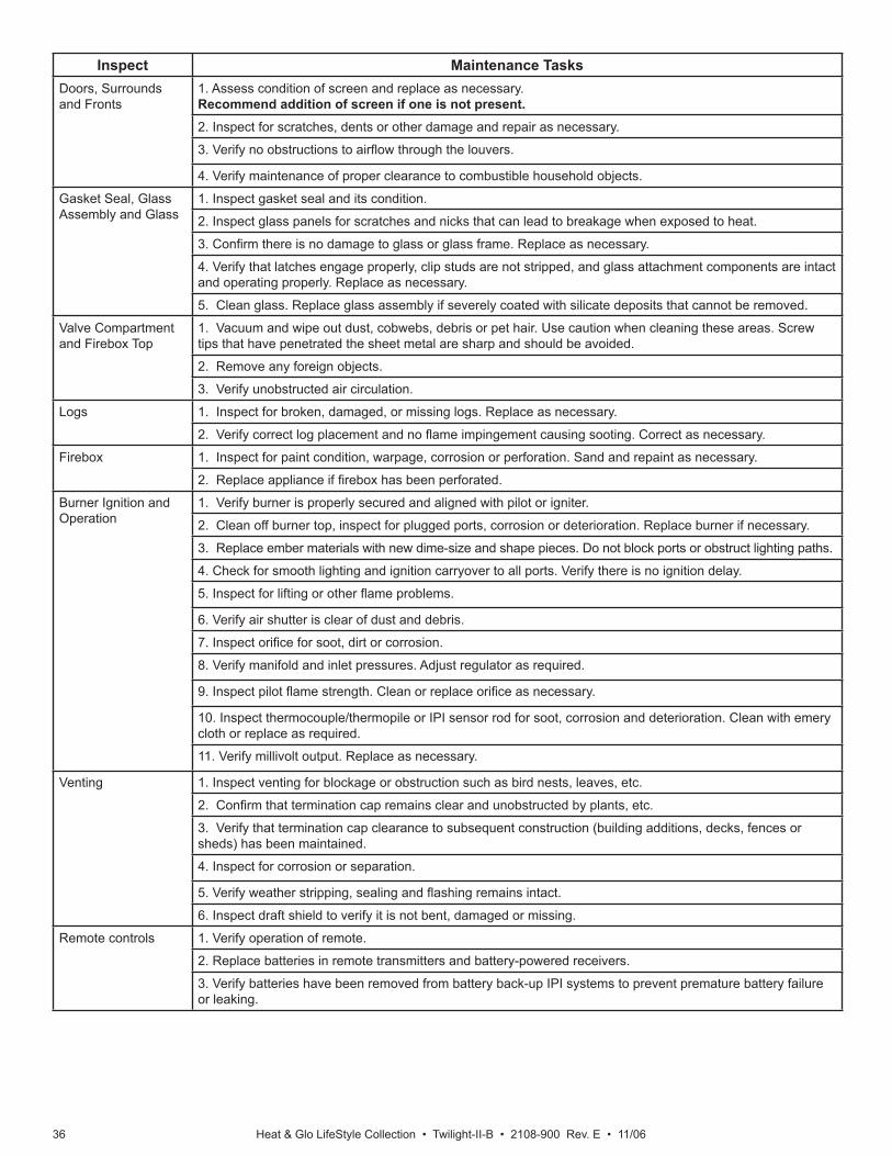
Heat & Glo LifeStyle Collection • Twilight-II-B • 2108-900 Rev. E • 11/0636
Inspect Maintenance TasksDoors, Surrounds and Fronts
1. Assess condition of screen and replace as necessary.Recommend addition of screen if one is not present.2. Inspect for scratches, dents or other damage and repair as necessary.
3. Verify no obstructions to airfl ow through the louvers.
4. Verify maintenance of proper clearance to combustible household objects.
Gasket Seal, Glass Assembly and Glass
1. Inspect gasket seal and its condition.
2. Inspect glass panels for scratches and nicks that can lead to breakage when exposed to heat.
3. Confi rm there is no damage to glass or glass frame. Replace as necessary.
4. Verify that latches engage properly, clip studs are not stripped, and glass attachment components are intact and operating properly. Replace as necessary.
5. Clean glass. Replace glass assembly if severely coated with silicate deposits that cannot be removed.
Valve Compartment and Firebox Top
1. Vacuum and wipe out dust, cobwebs, debris or pet hair. Use caution when cleaning these areas. Screw tips that have penetrated the sheet metal are sharp and should be avoided.
2. Remove any foreign objects.
3. Verify unobstructed air circulation.
Logs 1. Inspect for broken, damaged, or missing logs. Replace as necessary.
2. Verify correct log placement and no fl ame impingement causing sooting. Correct as necessary.
Firebox 1. Inspect for paint condition, warpage, corrosion or perforation. Sand and repaint as necessary.
2. Replace appliance if fi rebox has been perforated.
Burner Ignition and Operation
1. Verify burner is properly secured and aligned with pilot or igniter.
2. Clean off burner top, inspect for plugged ports, corrosion or deterioration. Replace burner if necessary.
3. Replace ember materials with new dime-size and shape pieces. Do not block ports or obstruct lighting paths.
4. Check for smooth lighting and ignition carryover to all ports. Verify there is no ignition delay.
5. Inspect for lifting or other fl ame problems.
6. Verify air shutter is clear of dust and debris.
7. Inspect orifi ce for soot, dirt or corrosion.
8. Verify manifold and inlet pressures. Adjust regulator as required.
9. Inspect pilot fl ame strength. Clean or replace orifi ce as necessary.
10. Inspect thermocouple/thermopile or IPI sensor rod for soot, corrosion and deterioration. Clean with emery cloth or replace as required.
11. Verify millivolt output. Replace as necessary.
Venting 1. Inspect venting for blockage or obstruction such as bird nests, leaves, etc.
2. Confi rm that termination cap remains clear and unobstructed by plants, etc.
3. Verify that termination cap clearance to subsequent construction (building additions, decks, fences or sheds) has been maintained.
4. Inspect for corrosion or separation.
5. Verify weather stripping, sealing and fl ashing remains intact.
6. Inspect draft shield to verify it is not bent, damaged or missing.
Remote controls 1. Verify operation of remote.
2. Replace batteries in remote transmitters and battery-powered receivers.
3. Verify batteries have been removed from battery back-up IPI systems to prevent premature battery failure or leaking.
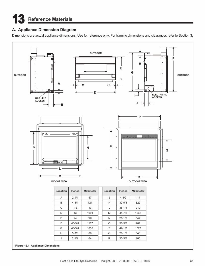
Heat & Glo LifeStyle Collection • Twilight-II-B • 2108-900 Rev. E • 11/06 37
A
B
C
D
C
F
G
H
I
J
K
L
M
N O
P
Q
R
E
INDOOR VIEW
ELECTRICALACCESSGAS LINE
ACCESS
OUTDOOR VIEW
Location Inches Millimeter Location Inches Millimeter
A 2-1/4 57 J 4-1/2 114
B 4-3/4 121 K 32-5/8 829
C 1/2 13 L 36-1/4 919
D 43 1091 M 41-7/8 1062
E 24 609 N 21-1/2 547
F 46-3/4 1187 O 38-5/8 981
G 40-3/4 1035 P 42-1/8 1070
H 3-3/8 86 Q 21-1/2 546
I 2-1/2 64 R 35-5/8 905
A. Appliance Dimension DiagramDimensions are actual appliance dimensions. Use for reference only. For framing dimensions and clearances refer to Section 3.
Figure 13.1 Appliance Dimensions
OUTDOOR
OUTDOOR
OUTDOOR
13 13 Reference Materials
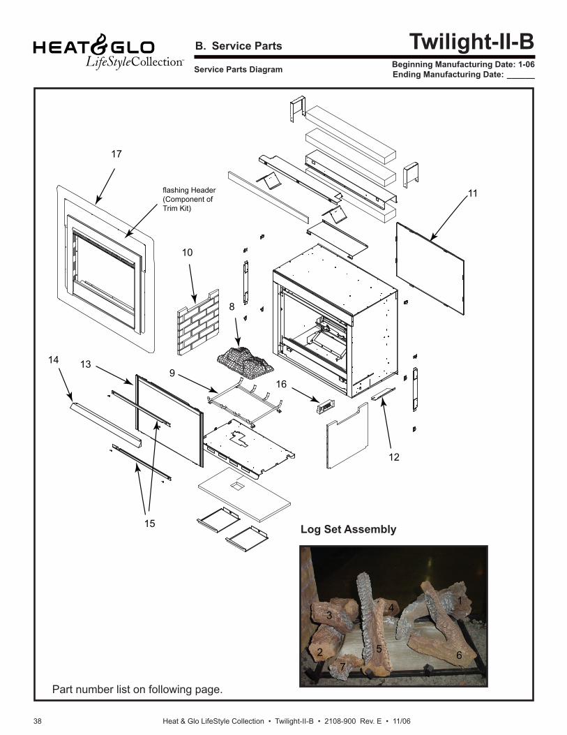
Heat & Glo LifeStyle Collection • Twilight-II-B • 2108-900 Rev. E • 11/0638
Service Parts Diagram
B. Service Parts Twilight-II-BBeginning Manufacturing Date: 1-06Ending Manufacturing Date: ______
8
9
10
11
12
1314
15
16
17
flashing Header(Component ofTrim Kit)
1
2
34
5 67
Log Set Assembly
Part number list on following page.
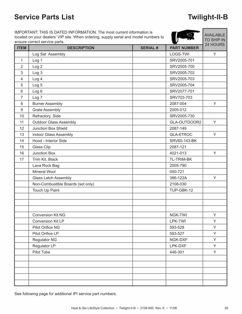
Heat & Glo LifeStyle Collection • Twilight-II-B • 2108-900 Rev. E • 11/06 39
Service Parts List
See following page for additional IPI service part numbers.
Twilight-II-B
IMPORTANT: THIS IS DATED INFORMATION. The most current information is located on your dealers’ VIP site. When ordering, supply serial and model numbers to ensure correct service parts.
AVAILABLE TO SHIP IN 24 HOURS
ITEM DESCRIPTION SERIAL # PART NUMBERLog Set Assembly LOGS-TWI Y
1 Log 1 SRV2005-7012 Log 2 SRV2005-7003 Log 3 SRV2005-7024 Log 4 SRV2005-7035 Log 5 SRV2005-7046 Log 6 SRV2077-7017 Log 7 SRV703-7038 Burner Assembly 2087-004 Y9 Grate Assembly 2005-012
10 Refractory, Side SRV2005-73011 Outdoor Glass Assembly GLA-OUTDOOR2 Y12 Junction Box Shield 2087-14913 Indoor Glass Assembly GLA-6TROC Y14 Hood - Interior Side SRV60-143-BK15 Glass Clip 2087-12116 Junction Box 4021-013 Y17 Trim Kit, Black TL-TRIM-BK
Lava Rock Bag 2005-790Mineral Wool 050-721Glass Latch Assembly 386-122A YNon-Combustible Boards (set only) 2108-030Touch Up Paint TUP-GBK-12
Conversion Kit NG NGK-TWI YConversion Kit LP LPK-TWI YPilot Orifi ce NG 593-528 YPilot Orifi ce LP 593-527 YRegulator NG NGK-DXF YRegulator LP LPK-DXF YPilot Tube 446-301 Y
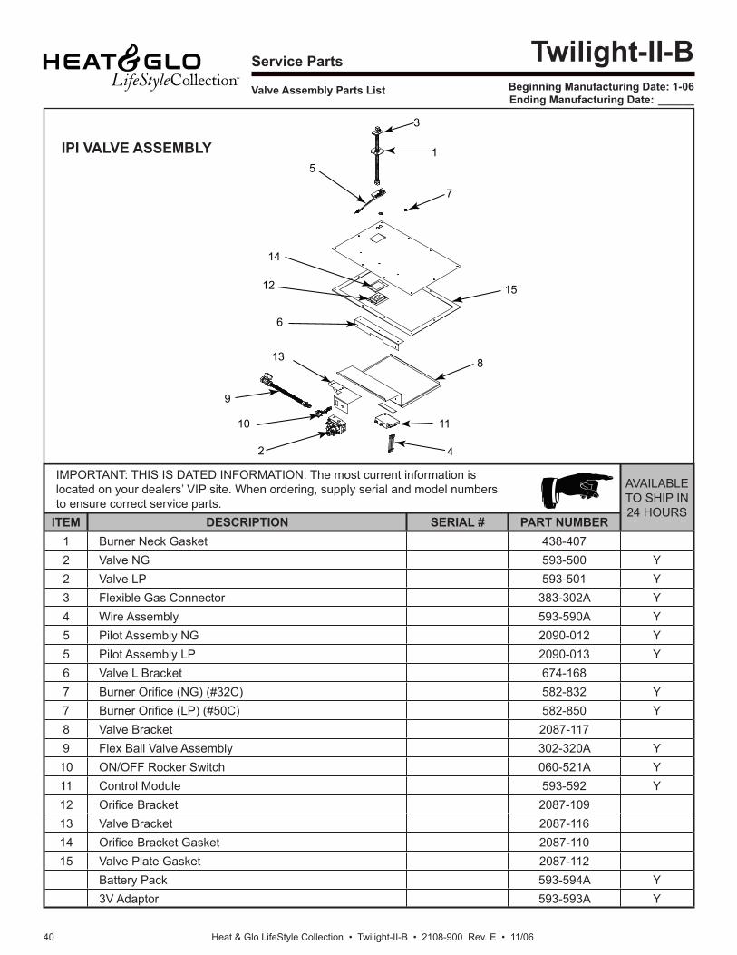
Heat & Glo LifeStyle Collection • Twilight-II-B • 2108-900 Rev. E • 11/0640
Service Parts
Valve Assembly Parts List
Twilight-II-BBeginning Manufacturing Date: 1-06Ending Manufacturing Date: ______
1
2
3
4
5
6
7
8
9
10 11
12
13
14
15
IMPORTANT: THIS IS DATED INFORMATION. The most current information is located on your dealers’ VIP site. When ordering, supply serial and model numbers to ensure correct service parts.
AVAILABLE TO SHIP IN 24 HOURS
ITEM DESCRIPTION SERIAL # PART NUMBER1 Burner Neck Gasket 438-4072 Valve NG 593-500 Y2 Valve LP 593-501 Y3 Flexible Gas Connector 383-302A Y4 Wire Assembly 593-590A Y5 Pilot Assembly NG 2090-012 Y5 Pilot Assembly LP 2090-013 Y6 Valve L Bracket 674-1687 Burner Orifi ce (NG) (#32C) 582-832 Y7 Burner Orifi ce (LP) (#50C) 582-850 Y8 Valve Bracket 2087-1179 Flex Ball Valve Assembly 302-320A Y
10 ON/OFF Rocker Switch 060-521A Y11 Control Module 593-592 Y12 Orifi ce Bracket 2087-10913 Valve Bracket 2087-11614 Orifi ce Bracket Gasket 2087-11015 Valve Plate Gasket 2087-112
Battery Pack 593-594A Y3V Adaptor 593-593A Y
IPI VALVE ASSEMBLY
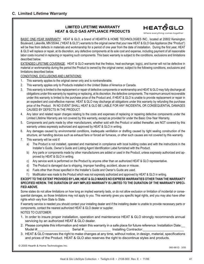
Heat & Glo LifeStyle Collection • Twilight-II-B • 2108-900 Rev. E • 11/06 41
© 2005 Hearth & Home Technologies Inc.
C. Limited Lifetime Warranty
LIMITED LIFETIME WARRANTYHEAT & GLO GAS APPLIANCE PRODUCTS
BASIC ONE-YEAR WARRANTY. HEAT & GLO, a brand of HEARTH & HOME TECHNOLOGIES INC., located at 20802 Kensington Boulevard, Lakeville, MN 55044, (“HEAT & GLO”) warrants to the original owner that your new HEAT & GLO Gas Appliance (the “Product”) will be free from defects in materials and workmanship for a period of one year from the date of installation. During the fi rst year, HEAT & GLO will replace or repair, at its discretion, any defective components at its sole cost and expense, including payment of all reasonable labor costs incurred in replacing or repairing such components. This basic warranty is subject to the conditions, exclusions and limitations described below.EXTENDED LIFETIME COVERAGE. HEAT & GLO warrants that the fi rebox, heat exchanger, log(s), and burner will not be defective in material or workmanship during the period the Product is owned by the original owner, subject to the following conditions, exclusions and limitations described below.CONDITIONS, EXCLUSIONS AND LIMITATIONS:1. This warranty applies to the original owner only and is nontransferable.2. This warranty applies only to Products installed in the United States of America or Canada.3. This warranty is limited to the replacement or repair of defective components or workmanship and HEAT & GLO may fully discharge all
obligations under this warranty by repairing or replacing, at its discretion, the defective components. The maximum amount recoverable under this warranty is limited to the purchase price of the Product and, if HEAT & GLO is unable to provide replacement or repair in an expedient and cost-effective manner, HEAT & GLO may discharge all obligations under this warranty by refunding the purchase price of the Product. IN NO EVENT SHALL HEAT & GLO BE LIABLE FOR ANY INCIDENTAL OR CONSEQUENTIAL DAMAGES CAUSED BY DEFECTS IN THE PRODUCT.
4. Any labor and related repair charges relating to the costs and expenses of replacing or repairing defective components under the Limited Lifetime Warranty are not covered by this warranty, except as provided for under the Basic One-Year Warranty.
5. Components and parts made by other manufacturers, whether sold with the Product or added thereafter, are NOT covered by this warranty unless expressly authorized and approved by HEAT & GLO in writing.
6. Any damages caused by environmental conditions, inadequate ventilation or drafting caused by tight sealing construction of the structure, air handling devices such as exhaust fans or forced air furnaces, or other such causes are not covered by this warranty.
7. This warranty will be void if: a) The Product is not installed, operated and maintained in compliance with local building codes and with the instructions in the
Installer’s Guide, Owner’s Guide and Listing Agent Identifi cation Label furnished with the Product. b) Any parts or components made by other manufacturers are added or used in the Product, unless expressly authorized and ap-
proved by HEAT & GLO in writing. c) Any service work is performed on the Product by anyone other than an authorized HEAT & GLO representative. d) The Product is damaged due to shipping, improper handling, accident, abuse or misuse. e) Fuels other than those specifi ed in the Installer’s Guide and Owner’s Guide are used. f ) Modifi cation was made to the Product which was not expressly authorized and approved by HEAT & GLO in writing.EXCEPT TO THE EXTENT PROVIDED BY LAW, HEAT & GLO MAKES NO EXPRESS WARRANTIES OTHER THAN THE WARRANTY SPECIFIED HEREIN. THE DURATION OF ANY IMPLIED WARRANTY IS LIMITED TO THE DURATION OF THE WARRANTY SPECI-FIED ABOVE. Some states do not allow limitations on how long an implied warranty lasts, or do not allow exclusion or limitation of incidental or conse-quential damages, so those limitations may not apply to you. This warranty gives you specifi c legal rights, and you may also have other rights which vary from State to State.If warranty service is needed you should contact your installing dealer and if the installing dealer is unable to provide necessary parts or components, contact the nearest authorized HEAT & GLO dealer or supplier.NOTES TO CUSTOMER:1. In order to insure proper installation, operation and maintenance HEAT & GLO strongly recommends annual
servicing by an authorized HEAT & GLO dealer.2. Please complete this information and retain this warranty in a safe place for future reference: Installation Date:__
Model #:_________________ Serial #:______________ Installing Contractor:______________________3. HEAT & GLO reserves the right to make changes at any time, without notice, in design, material, specifi cations
and prices of the Product. HEAT & GLO also reserves the right to discontinue styles and products.
060-981D 3/05
Heat & Glo LifeStyle Collection • Twilight-II-B • 2108-900 Rev. E • 11/0642
Heat & Glo LifeStyle Collection, a brand of Hearth & Home Technologies Inc. 20802 Kensington Boulevard, Lakeville, MN 55044
www.Heatnglolifestyle.com
- NOTES -
________________________________________________________________________________
________________________________________________________________________________
________________________________________________________________________________
________________________________________________________________________________
________________________________________________________________________________
________________________________________________________________________________
________________________________________________________________________________
________________________________________________________________________________
________________________________________________________________________________
D. Contact Information
Printed in U.S.A. - Copyright 2006
This product may be covered by one or more of the following patents: (United States) 4593510, 4686807, 4766876, 4793322, 4811534, 5000162, 5016609, 5076254, 5113843, 5191877, 5218953, 5263471, 5328356, 5341794, 5347983, 5429495, 5452708, 5542407, 5601073, 5613487, 5647340, 5688568, 5762062, 5775408, 5890485, 5931661, 5941237, 5947112, 5996575, 6006743, 6019099, 6048195, 6053165, 6145502, 6170481, 6237588, 6296474, 6374822, 6413079, 6439226, 6484712, 6543698, 6550687, 6601579, 6672860, 6688302B2, 6715724B2, 6729551, 6736133, 6748940, 6748942, 6769426, 6774802, 6796302, 6840261, 6848441, 6863064, 6866205, 6869278, 6875012, 6880275, 6908039, 6919884, D320652, D445174, D462436; (Canada) 1297749, 2195264, 2225408, 2313972; (Australia) 780250, 780403, 1418504 or other U.S. and foreign patents pending.
DO NOT DISCARD THIS MANUAL
CAUTION
• Leave this manual with party responsible for use and operation.
• Important operating and maintenance instructions included.
• Read, understand and follow these instructions for safe installation and operation.
Please contact your Heat & Glo dealer with any questions or concerns. For the location of your nearest Heat & Glo dealer,
please visit www.Heatnglolifestyle.com.