Embed Size (px)
Citation preview
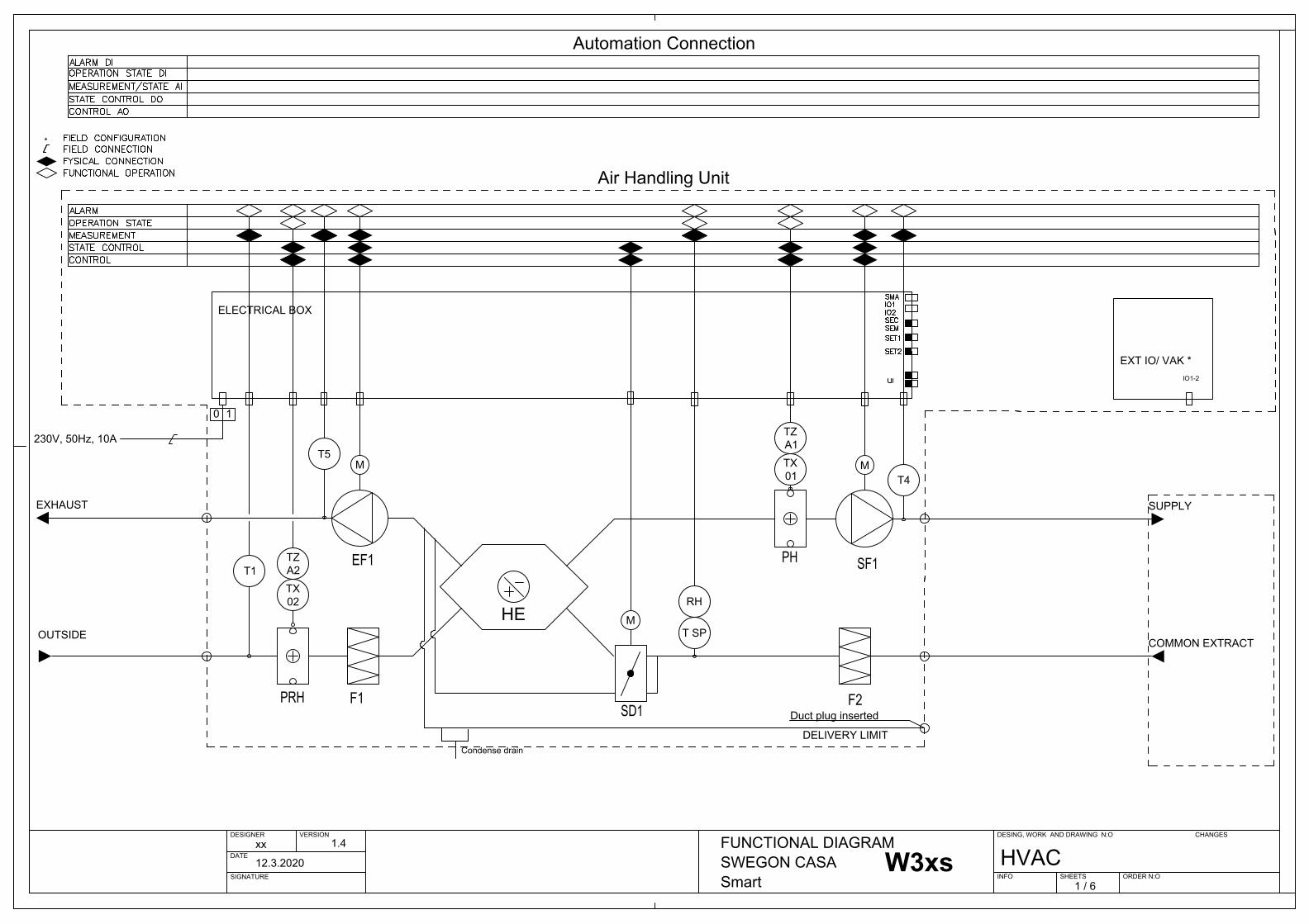
EF1 SF1PH
F1+F2
ELECTRICAL BOX
EXHAUST SUPPLY
COMMON EXTRACT
SD1F3
DELIVERY LIMIT
CH EXHAUSTPRH
TX
SD2
SD1
M
SDHE SDCW
SDHE SDHWM
0 1
SET*
EXT IO/ VAK *
SMA
UP
SET*SET*
M
TX
SDHW
TX
TX
DESIGNER VERSION
DATE
SIGNATURE
DESING, WORK AND DRAWING N:O
INFO SHEETS ORDER N:O
CHANGESxx 1.4
12.3.2020
FUNCTIONAL DIAGRAMSWEGON CASA Smart 1 / 6
HVAC
FLK
Room Temp
SET*SET*SET*SET*SET*SET*SET*SET*SET*SET*SET*SET*
TX
SET*SET*SET*
TX
EF1 SF1
F1 F2
CONNECTION BOARD
0 1
IO1IO2
ModbusRTU
IO3IO4IO5AO4
230V, 50Hz, 10A
SMA
CH
IO3IO4IO5AO4
Condense drain
PH
230V, 50Hz, 10A
Condense drain
AO4
*
S_P
E_P
SD2
M
EF1 SF1PH
F1
T1
ELECTRICAL BOX
SD1 F2PRH
0 1
230V, 50Hz, 16A
Condense drain
EXT IO/ VAK *
IO1IO2
HE
HE
Switch
CH
CH EXHAUST
Cooker Hood Exhaust
OUTSIDE
SD1
M
IO3-5IO3-5
EF1 SF1PH
F1+F2
ELECTRICAL BOX
SD1F3PRH
0 1
230V, 50Hz, 10A
Condense drain
EXT IO/ VAK *
IO1IO2
HEWARM WATER
M
WARM WATER
M
COOL LIQUID
M
M
EF1 SF1PH
F1+F2
ELECTRICAL BOX
F3PRH
0 1
230V, 50Hz, 10A
Condense drain
EXT IO/ VAK *
IO1IO2
HEWARM WATER
W3W3 EconoW4W5
EF1 SF1PH
F1
ELECTRICAL BOX
SD1 F2PRH
0 1
230V, 50Hz, 16A
Condense drain
EXT IO/ VAK *
IO1IO2
W9
EF1 SF1PH
F1+F2
ELECTRICAL BOX
F3PRH
0 1
230V, 50Hz, 10A
Condense drain
EXT IO/ VAK *
IO1IO2
HEWARM WATER
W9 EconoR3
EXT IO/ VAK *
EF1 SF1
F1 F2
CONNECTION BOARD IO1IO2
230V, 50Hz, 10A
PH
HE
R5-H
EXT IO/ VAK *
EF1 SF1
F1 F2
CONNECTION BOARD IO1IO2
230V, 50Hz, 10A
PH
HE
R2
EXT IO/ VAK *
EF1 SF1
F1 F2
CONNECTION BOARD
0 1
IO1IO2
230V, 50Hz, 10A
Condense drain
PH
HE
R5
EXT IO/ VAK *
EF1 SF1
F1 F2
CONNECTION BOARD IO1IO2
230V, 50Hz, 10A
PH
HE
R7/R7-H
EXT IO/ VAK *
EF1 SF1
F1 F2
CONNECTION BOARD IO1IO2
230V, 50Hz, 10A
HE
R9/R9-H
EXT IO/ VAK *
EF1 SF1
F1 F2
CONNECTION BOARD
230V, 50Hz, 10A
HE
R15/R15-H
Automation Connection
Air Handling Unit
T5 T2
T1 T3
T4
TZA2TX02
TZA1TX01
T SP
RH
CO2
VOC
M M
M
TZA2TX02
M
TZA1TX01 T4
M
M
T SP
RH
TZA2TX02
T1
M
TZA1TX01 T4
M
M
T SP
RH
TZA2TX02
T1
T5M
T2T3
T4M
MT SP
RH
TZA2TX02
T1
T5M
T3
T4M
T SP
RH
EF1 SF1PH
F1+F2
ELECTRICAL BOX
SD1F3PRH
0 1
230V, 50Hz, 10A
Condense drain
EXT IO/ VAK *
IO1IO2
HE
T5 T2
T1 T3
T4
TZA2TX02
TZA1TX01
T SP
RH
M M
M
EF1 SF1PH
F1+F2
ELECTRICAL BOX
SD1F3PRH
0 1
230V, 50Hz, 10A
Condense drain
EXT IO/ VAK *
IO1IO2
HEWARM WATER
W4 Econo
TZA2TX02
T1
T5M
T2T3
T4M
MT SP
RH
T1
T4
TZA2TX02
M M
T SP
RH
T1
M
TZA2TX02
MT4
T SP
RH
T1
M
TZA2TX02
MT4
T SP
RH
T1
M
TZA2TX02
MT4
T SP
RH
T1
M
TZA2TX02
MT4
T SP
RH
T1
M MT4
T SP
RH
T1
M MT4
T SP
RH
T5T5T5T5
SMA
SMA
SEMSEC
Outside Temp
Supply TempSupply TempSupply Temp
Water Temp
DO1 AO4DO2 DO3DO4DO5SET Relay1 SET Relay2DI1DI2 DI3DI4DI5AI1AI2 AI3AI4AI5 DO3
EXT IO/ VAK *IO1-2
Duct plug insertedDuct plug insertedDuct plug insertedDuct plug insertedDuct plug insertedDuct plug insertedDuct plug inserted
T5T5
T3T3T3T3 T3
TR
Room Temp
TR
Room Temp
Connection module
EF1 SF1PH
F1
ELECTRICAL BOX
SD1F2PRH
0 1
230V, 50Hz, 10A
Condense drain
HE
W3xs
T5
T1
T4
TZA2TX02
TZA1TX01
T SP
RH
M M
M
EXT IO/ VAK *
Duct plug inserted
SD1
M
EF1 SF1PH
F1
ELECTRICAL BOX
SD1F2PRH
0 1
230V, 50Hz, 10A
Condense drain
HE
W4xs
T5
T1
T4
TZA2TX02
TZA1TX01
T SP
RH
M M
M
EXT IO/ VAK *
Duct plug inserted
TX
Water Temp
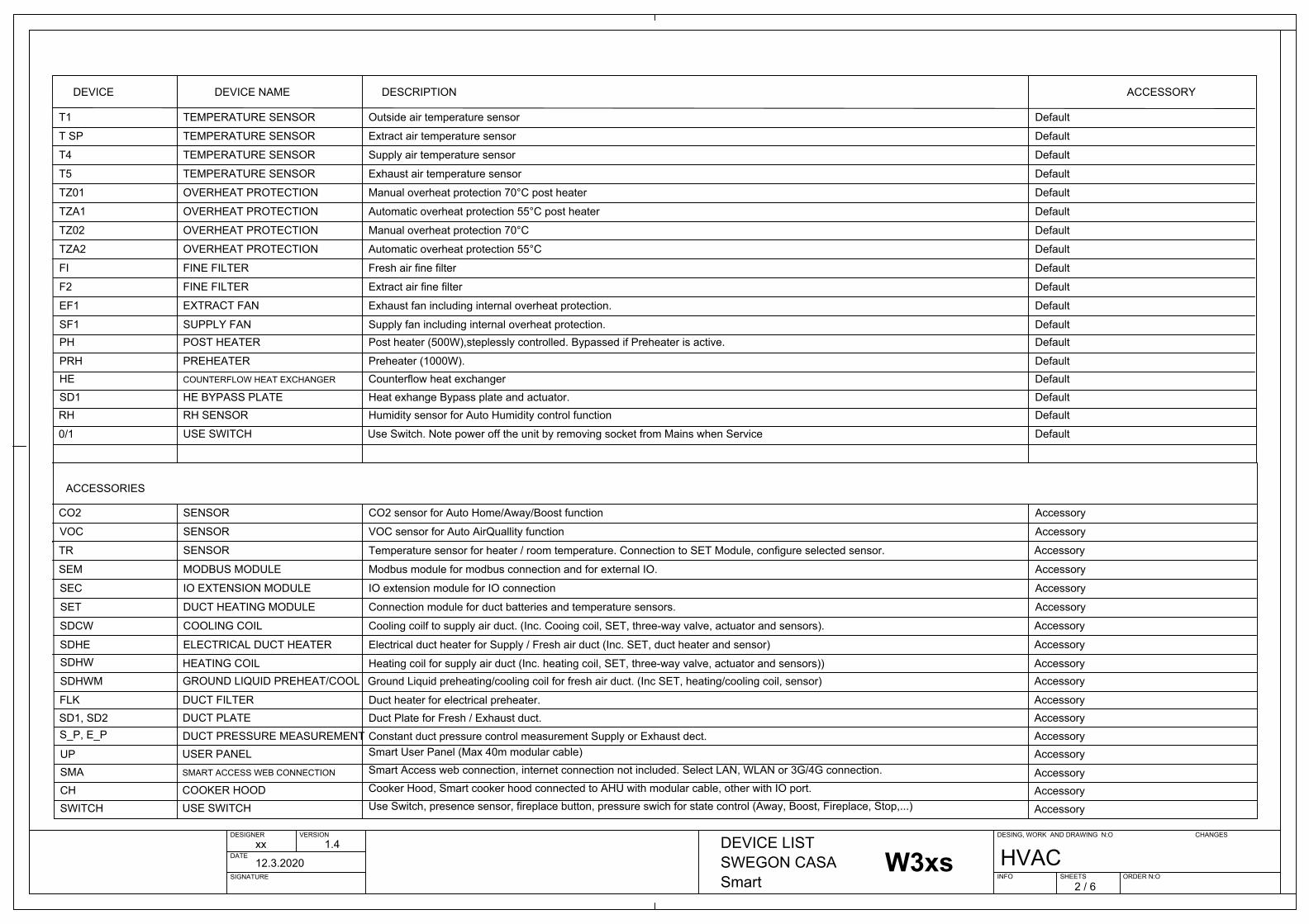
DEVICE DEVICE NAME ACCESSORYDESCRIPTION
DESIGNER VERSION
DATE
SIGNATURE
DESING, WORK AND DRAWING N:O
INFO SHEETS ORDER N:O
CHANGESxx 1.4
12.3.2020
DEVICE LISTSWEGON CASA Smart 2 / 6
HVAC
TEMPERATURE SENSOR
TEMPERATURE SENSOR Supply air temperature sensor
OVERHEAT PROTECTION Manual overheat protection 70°C post heater
Extract air temperature sensor
OVERHEAT PROTECTION Manual overheat protection 70°C
TEMPERATURE SENSOR
TEMPERATURE SENSOR Supply temperature before post heater
Outside air temperature sensor
Temperature sensor for heater / room temperature. Connection to SET Module, configure selected sensor.
TEMPERATURE SENSOR Exhaust air temperature sensor
COOLING COIL
Electrical duct heater for Supply / Fresh air duct (Inc. SET, duct heater and sensor)ELECTRICAL DUCT HEATER
Cooling coilf to supply air duct. (Inc. Cooing coil, SET, three-way valve, actuator and sensors).
RH SENSOR Humidity sensor for Auto Humidity control function
SENSOR VOC sensor for Auto AirQuallity function
SENSOR CO2 sensor for Auto Home/Away/Boost function
OVERHEAT PROTECTION Automatic overheat protection 55°C post heater
OVERHEAT PROTECTION Automatic overheat protection 55°C
DUCT HEATING MODULE Connection module for duct batteries and temperature sensors.
MODBUS MODULE Modbus module for modbus connection and for external IO.
TZ01
TZ02
T1
T2
T3
T4
TR
T5
SDHWM
SDHW
RH
VOC
CO2
TZA1
TZA2
SET
SEM
Default
FI + F2 COARSE / FINE FILTER Fresh air coarse + fine filter
F3 FINE FILTER Extract air fine filter
SF1PH
EF1
PRH
EXTRACT FAN
SUPPLY FANPOST HEATER
PREHEATER
Exhaust fan including internal overheat protection.
Supply fan including internal overheat protection.Post heater (500W),steplessly controlled. Bypassed if Preheater is active.
Preheater (1000W).HE COUNTERFLOW HEAT EXCHANGER
Heat exhange Bypass plate and actuator.Counterflow heat exchanger
SD1 HE BYPASS PLATE
Default
Default
Default
Default
Default
Default
Default
Default
Default
Default
Default
DefaultDefault
DefaultDefaultDefaultDefault
Accessory
Accessory
SENSOR AccessoryVOC sensor for Auto AirQuallity function SENSORVOC Accessory SELECTED
Accessory SELECTEDCO2 sensor for Auto Home/Away/Boost functionSENSORCO2
SEC IO EXTENSION MODULE IO extension module for IO connection
Accessory
Accessory
Accessory
SDCW
SDHE
FLKSD1, SD2S_P, E_P
HEATING COILGROUND LIQUID PREHEAT/COOL
DUCT FILTERDUCT PLATEDUCT PRESSURE MEASUREMENT
Ground Liquid preheating/cooling coil for fresh air duct. (Inc SET, heating/cooling coil, sensor)
Accessory
Accessory
AccessoryAccessory
AccessoryAccessoryAccessoryAccessory
AccessoryAccessoryAccessory
Heating coil for supply air duct (Inc. heating coil, SET, three-way valve, actuator and sensors))
Duct heater for electrical preheater.Duct Plate for Fresh / Exhaust duct.Constant duct pressure control measurement Supply or Exhaust dect.
ACCESSORIES
SDCW COOLING COIL Cooling coilf to supply air duct. (Inc. Cooing coil, SET, three-way valve, actuator and sensors). Accessory SELECTED
SDHE ELECTRICAL DUCT HEATER Electrical duct heater for Supply / Fresh air duct (Inc. SET, duct heater and sensor) Accessory SELECTEDSDHE ELECTRICAL DUCT HEATER Electrical duct heater for Supply / Fresh air duct (Inc. SET, duct heater and sensor) Accessory SELECTEDSDHW HEATING COIL Heating coil for supply air duct (Inc. heating coil, SET, three-way valve, actuator and sensors)) Accessory SELECTEDSDHWM GROUND LIQUID PREHEAT/COOL Ground Liquid preheating/cooling coil for fresh air duct. (Inc SET, heating/cooling coil, sensor) Accessory SELECTED
FLK DUCT FILTER Duct heater for electrical preheater. Accessory SELECTEDSD1, SD2 DUCT PLATE Duct Plate for Fresh / Exhaust duct. Accessory SELECTEDSD1, SD2 DUCT PLATE Duct Plate for Fresh / Exhaust duct. Accessory SELECTEDSD1, SD2 DUCT PLATE Duct Plate for Fresh / Exhaust duct. Accessory SELECTEDSD1, SD2 DUCT PLATE Duct Plate for Fresh / Exhaust duct. Accessory SELECTED
Accessory SELECTEDConstant duct pressure control measurement Supply or Exhaust dect.DUCT PRESSURE MEASUREMENTS_P, E_P Accessory SELECTEDConstant duct pressure control measurement Supply or Exhaust dect.DUCT PRESSURE MEASUREMENTS_P, E_P
UPSMACHSWITCH
0/1 USE SWITCH Use Switch. Note power off the unit by removing socket from Mains when Service Default
USER PANELSMART ACCESS WEB CONNECTION
COOKER HOODUSE SWITCH
Smart User Panel (Max 40m modular cable)Smart Access web connection, internet connection not included. Select LAN, WLAN or 3G/4G connection.Cooker Hood, Smart cooker hood connected to AHU with modular cable, other with IO port.Use Switch, presence sensor, fireplace button, pressure swich for state control (Away, Boost, Fireplace, Stop,...)
UP USER PANEL Smart User Panel (Max 40m modular cable) Accessory SELECTEDSMA SMART ACCESS WEB CONNECTION Smart Access web connection, internet connection not included. Select LAN, WLAN or 3G/4G connection. Accessory SELECTEDCH COOKER HOOD Cooker Hood, Smart cooker hood connected to AHU with modular cable, other with IO port. Accessory SELECTEDCH COOKER HOOD Cooker Hood, Smart cooker hood connected to AHU with modular cable, other with IO port. Accessory SELECTED
SEM MODBUS MODULE Modbus module for modbus connection and for external IO. Accessory SELECTED
SEC IO EXTENSION MODULE IO extension module for IO connection Accessory SELECTED
W3W3 EconoW4W5W9W9 EconoR3R5-HR2R5R7/R7-HR9/R9-HR15/R15-HW4 Econo
SMA SMART ACCESS WEB CONNECTION Smart Access web connection, internet connection not included. Select LAN, WLAN or 3G/4G connection. Accessory SELECTED
SWITCH USE SWITCH Use Switch, presence sensor, fireplace button, pressure swich for state control (Away, Boost, Fireplace, Stop,...) Accessory SELECTED
DUCT HEATING MODULE Connection module for duct batteries and temperature sensors. Accessory SELECTEDSET
DEVICE DEVICE NAME ACCESSORYDESCRIPTION
TEMPERATURE SENSOR
TEMPERATURE SENSOR Supply air temperature sensor
OVERHEAT PROTECTION Manual overheat protection 70°C post heater
Exhaust air temperatre sensor
OVERHEAT PROTECTION Manual overheat protection 70°C
TEMPERATURE SENSOR Outside air temperature sensor
RH SENSOR Humidity sensor for Auto Humidity control function
OVERHEAT PROTECTION Automatic overheat protection 55°C post heater
OVERHEAT PROTECTION Automatic overheat protection 55°C
TZ01
TZ02
T1
T SP
T4
RH
TZA1
TZA2
Default
FI FINE FILTER Fresh air coarse / fine filter
F2 FINE FILTER Extract air fine filter
SF1PH
EF1
PRH
EXTRACT FAN
SUPPLY FANPOST HEATER
PREHEATER
Exhaust fan including internal overheat protection.
Supply fan including internal overheat protection.Post heater (500W),steplessly controlled. Bypassed if Preheater is active.
Preheater (1000W).HE COUNTERFLOW HEAT EXCHANGER
Heat exhange Bypass plate and actuator.Counterflow heat exchanger
SD1 HE BYPASS PLATE
Default
Default
Default
Default
Default
Default
Default
Default
Default
Default
DefaultDefault
DefaultDefaultDefaultDefault
0/1 USE SWITCH Use Switch. Note power off the unit by removing socket from Mains when Service Default
DEVICE DEVICE NAME ACCESSORYDESCRIPTION
TEMPERATURE SENSOR
TEMPERATURE SENSOR Supply air temperature sensor
Extract air temperature sensor
OVERHEAT PROTECTION Manual overheat protection 70°C
TEMPERATURE SENSOR
TEMPERATURE SENSOR Supply temperature before post heater
Outside air temperature sensor
TEMPERATURE SENSOR Exhaust air temperature sensor
RH SENSOR Humidity sensor for Auto Humidity control function
OVERHEAT PROTECTION Automatic overheat protection 55°C
TZ02
T1
T2
T SP
T4
T5
RH
TZA2
Default
FI + F2 COARSE / FINE FILTER Fresh air coarse + fine filter
F3 FINE FILTER Extract air fine filter
SF1PH
EF1
PRH
EXTRACT FAN
SUPPLY FANPOST HEATER
PREHEATER
Exhaust fan including internal overheat protection.
Supply fan including internal overheat protection.Post heater, water based radiator. Including freezing protection.
Preheater (1000W).HE COUNTERFLOW HEAT EXCHANGER
Heat exhange Bypass plate and actuator.Counterflow heat exchanger
SD1 HE BYPASS PLATE
Default
Default
Default
Default
Default
Default
Default
Default
Default
DefaultDefault
DefaultDefaultDefaultDefault
0/1 USE SWITCH Use Switch. Note power off the unit by removing socket from Mains when Service Default
DEVICE DEVICE NAME ACCESSORYDESCRIPTION
TEMPERATURE SENSOR
TEMPERATURE SENSOR Supply air temperature sensor
OVERHEAT PROTECTION Manual overheat protection 70°C post heater
Extract air temperature sensor
OVERHEAT PROTECTION Manual overheat protection 70°C
TEMPERATURE SENSOR
TEMPERATURE SENSOR Supply temperature before post heater
Outside air temperature sensor
TEMPERATURE SENSOR Exhaust air temperature sensor
RH SENSOR Humidity sensor for Auto Humidity control function
OVERHEAT PROTECTION Automatic overheat protection 55°C post heater
OVERHEAT PROTECTION Automatic overheat protection 55°C
TZ01
TZ02
T1
T2
T3
T4
T5
RH
TZA1
TZA2
Default
FI + F2 COARSE / FINE FILTER Fresh air coarse + fine filter
F3 FINE FILTER Extract air fine filter
SF1PH
EF1
PRH
EXTRACT FAN
SUPPLY FANPOST HEATER
PREHEATER
Exhaust fan including internal overheat protection.
Supply fan including internal overheat protection.Post heater (500W),steplessly controlled. Bypassed if Preheater is active.
Preheater (1000W).HE COUNTERFLOW HEAT EXCHANGER
Heat exhange Bypass plate and actuator.Counterflow heat exchanger
SD1 HE BYPASS PLATE
Default
Default
Default
Default
Default
Default
Default
Default
Default
Default
Default
DefaultDefault
DefaultDefaultDefaultDefault
0/1 USE SWITCH Use Switch. Note power off the unit by removing socket from Mains when Service Default
DEVICE DEVICE NAME ACCESSORYDESCRIPTION
TEMPERATURE SENSOR
TEMPERATURE SENSOR Supply air temperature sensor
Extract air temperature sensor
OVERHEAT PROTECTION Manual overheat protection 70°C
TEMPERATURE SENSOR
TEMPERATURE SENSOR Supply temperature before post heater
Outside air temperature sensor
TEMPERATURE SENSOR Exhaust air temperature sensor
RH SENSOR Humidity sensor for Auto Humidity control function
OVERHEAT PROTECTION Automatic overheat protection 55°C
TZ02
T1
T2
T SP
T4
T5
RH
TZA2
Default
FI + F2 COARSE / FINE FILTER Fresh air coarse + fine filter
F3 FINE FILTER Extract air fine filter
SF1PH
EF1
PRH
EXTRACT FAN
SUPPLY FANPOST HEATER
PREHEATER
Exhaust fan including internal overheat protection.
Supply fan including internal overheat protection.Post heater, water based radiator. Including freezing protection.
Preheater (1000W).HE COUNTERFLOW HEAT EXCHANGER
Heat exhange Bypass plate and actuator.Counterflow heat exchanger
SD1 HE BYPASS PLATE
Default
Default
Default
Default
Default
Default
Default
Default
Default
DefaultDefault
DefaultDefaultDefaultDefault
0/1 USE SWITCH Use Switch. Note power off the unit by removing socket from Mains when Service Default
DEVICE DEVICE NAME ACCESSORYDESCRIPTION
TEMPERATURE SENSOR
TEMPERATURE SENSOR Supply air temperature sensor
OVERHEAT PROTECTION Manual overheat protection 70°C post heater
Extract air temperature sensor
OVERHEAT PROTECTION Manual overheat protection 70°C
TEMPERATURE SENSOR Outside air temperature sensor
RH SENSOR Humidity sensor for Auto Humidity control function
OVERHEAT PROTECTION Automatic overheat protection 55°C post heater
OVERHEAT PROTECTION Automatic overheat protection 55°C
TZ01
TZ02
T1
T3
T4
RH
TZA1
TZA2
Default
F1 FINE FILTER Fresh air fine filter
F2 FINE FILTER Extract air fine filter
SF1PH
EF1
PRH
EXTRACT FAN
SUPPLY FANPOST HEATER
PREHEATER
Exhaust fan including internal overheat protection.
Supply fan including internal overheat protection.Post heater (900W),steplessly controlled. Bypassed if Preheater is active.
Preheater (750W).HE COUNTERFLOW HEAT EXCHANGER
Heat exhange Bypass plate and actuator.Counterflow heat exchanger
SD1 HE BYPASS PLATE
Default
Default
Default
Default
Default
Default
Default
Default
Default
DefaultDefault
DefaultDefaultDefaultDefault
0/1 USE SWITCH Use Switch. Note power off the unit by removing socket from Mains when Service Default
DEVICE DEVICE NAME ACCESSORYDESCRIPTION
TEMPERATURE SENSOR
TEMPERATURE SENSOR Supply air temperature sensor
Extract air temperature sensor
OVERHEAT PROTECTION Manual overheat protection 70°C
TEMPERATURE SENSOR Outside air temperature sensor
RH SENSOR Humidity sensor for Auto Humidity control function
OVERHEAT PROTECTION Automatic overheat protection 55°C
TZ02
T1
T SP
T4
RH
TZA2
Default
F1 FINE FILTER Fresh air fine filter
F2 FINE FILTER Extract air fine filter
SF1PH
EF1
PRH
EXTRACT FAN
SUPPLY FANPOST HEATER
PREHEATER
Exhaust fan including internal overheat protection.
Supply fan including internal overheat protection.Post heater, water based radiator. Including freezing protection.
Preheater (750W).HE COUNTERFLOW HEAT EXCHANGER
Heat exhange Bypass plate and actuator.Counterflow heat exchanger
SD1 HE BYPASS PLATE
Default
DefaultDefault
Default
Default
Default
Default
Default
DefaultDefault
DefaultDefaultDefaultDefault
0/1 USE SWITCH Use Switch. Note power off the unit by removing socket from Mains when Service Default
T5 TEMPERATURE SENSOR Exhaust air temperature sensor
T3 TEMPERATURE SENSOR Water temperature sensor DefaultT5 TEMPERATURE SENSOR Exhaust air temperature sensor Default
T3 TEMPERATURE SENSOR Water temperature sensor DefaultT3 TEMPERATURE SENSOR Water temperature sensor Default
DEVICE DEVICE NAME ACCESSORYDESCRIPTION
TEMPERATURE SENSOR
TEMPERATURE SENSOR Supply / Exhaust (Mirrored) air temperature sensor
Extract / Outside(Mirrored) air temperature sensor
TEMPERATURE SENSOR Outside / Extract(Mirrored) air temperature sensor
RH SENSOR Humidity sensor for Auto Humidity control function
T1
T3
T4
RH
Default
FI FINE FILTER Fresh air fine filter
F2 FINE FILTER Extract air fine filter
SF1
EF1 EXTRACT FAN
SUPPLY FAN
Exhaust fan including internal overheat protection.
Supply fan including internal overheat protection.HE ROTATING HEATEXCHANGER Rotor
Default
Default
Default
Default
Default
Default
Default
Default
Default
Default
Default
Default
DEVICE DEVICE NAME ACCESSORYDESCRIPTION
TEMPERATURE SENSOR
TEMPERATURE SENSOR Supply air temperature sensor
OVERHEAT PROTECTION Manual overheat protection 70°C post heater
Extract air temperature sensor included in sensor packet
TEMPERATURE SENSOR Outside air temperature sensor
RH SENSOR Humidity sensor for Auto Humidity control function
OVERHEAT PROTECTION Automatic overheat protection 55°C post heater
TZ01
T1
T SP
T4
RH
TZA1
Default
FI FINE FILTER Fresh air fine filter
F2 FINE FILTER Extract air fine filter
SF1PH
EF1 EXTRACT FAN
SUPPLY FANPOST HEATER
Exhaust fan including internal overheat protection.
Supply fan including internal overheat protection.Post heater,steplessly controlled.
HE ROTATING HEATEXCHANGER Rotor
Default
Default
Default
Default
Default
Default
Default
Default
DefaultDefault
Default
DEVICE DEVICE NAME ACCESSORYDESCRIPTION
TEMPERATURE SENSOR
TEMPERATURE SENSOR Supply air temperature sensor
OVERHEAT PROTECTION Manual overheat protection 70°C post heater
Extract air temperature sensor included in sensor package
TEMPERATURE SENSOR Outside air temperature sensor
RH SENSOR Humidity sensor for Auto Humidity control function
OVERHEAT PROTECTION Automatic overheat protection 55°C post heater
TZ01
T1
T SP
T4
RH
TZA1
Default
FI FINE FILTER Fresh air fine filter
F2 FINE FILTER Extract air fine filter
SF1PH
EF1 EXTRACT FAN
SUPPLY FANPOST HEATER
Exhaust fan including internal overheat protection.
Supply fan including internal overheat protection.Post heater,steplessly controlled. If Unit Equipped with postheater.
HE ROTATING HEATEXCHANGER Rotor
Default
Default
Default
Default
Default
Default
Default
Default
Default
Default0/1 USE SWITCH Use Switch. Note power off the unit by removing socket from Mains when Service Default
T5 (only Horizontal units) TEMPERATURE SENSOR Exhaust / Supply (Mirrored) air temperature sensor
DEVICE DEVICE NAME ACCESSORYDESCRIPTION
TEMPERATURE SENSOR
TEMPERATURE SENSOR Supply / Exhaust (Mirrored) air temperature sensor
OVERHEAT PROTECTION Manual overheat protection 70°C post heater
Extract / Outside(Mirrored) air temperature sensor
TEMPERATURE SENSOR Outside / Extract(Mirrored) air temperature sensor
RH SENSOR Humidity sensor for Auto Humidity control function
OVERHEAT PROTECTION Automatic overheat protection 55°C post heater
TZ01
T1
T3
T4
RH
TZA1
Default
FI FINE FILTER Fresh air fine filter
F2 FINE FILTER Extract air fine filter
SF1PH
EF1 EXTRACT FAN
SUPPLY FANPOST HEATER
Exhaust fan including internal overheat protection.
Supply fan including internal overheat protection.Post heater,steplessly controlled. If Unit Equipped with postheater.
HE ROTATING HEATEXCHANGER Rotor
Default
Default
Default
Default
Default
Default
Default
Default
Default
Default
Default
Default
T5 TEMPERATURE SENSOR Exhaust / Supply (Mirrored) air temperature sensor
DEVICE DEVICE NAME ACCESSORYDESCRIPTION
TEMPERATURE SENSOR
TEMPERATURE SENSOR Supply / Exhaust (Mirrored) air temperature sensor
OVERHEAT PROTECTION Manual overheat protection 70°C post heater
Extract / Outside(Mirrored) air temperature sensor
TEMPERATURE SENSOR Outside / Extract(Mirrored) air temperature sensor
RH SENSOR Humidity sensor for Auto Humidity control function
OVERHEAT PROTECTION Automatic overheat protection 55°C post heater
TZ01
T1
T3
T4
RH
TZA1
Default
FI FINE FILTER Fresh air fine filter
F2 FINE FILTER Extract air fine filter
SF1PH
EF1 EXTRACT FAN
SUPPLY FANPOST HEATER
Exhaust fan including internal overheat protection.
Supply fan including internal overheat protection.Post heater,steplessly controlled. If Unit Equipped with postheater.
HE ROTATING HEATEXCHANGER Rotor
Default
Default
Default
Default
Default
Default
Default
Default
Default
Default
Default
Default
T5 (only Horizontal units) TEMPERATURE SENSOR Exhaust / Supply (Mirrored) air temperature sensor
DEVICE DEVICE NAME ACCESSORYDESCRIPTION
TEMPERATURE SENSOR
TEMPERATURE SENSOR Supply / Exhaust (Mirrored) air temperature sensor
Extract / Outside(Mirrored) air temperature sensor
TEMPERATURE SENSOR Outside / Extract(Mirrored) air temperature sensor
RH SENSOR Humidity sensor for Auto Humidity control function
T1
T3
T4
RH
Default
FI FINE FILTER Fresh air fine filter
F2 FINE FILTER Extract air fine filter
SF1
EF1 EXTRACT FAN
SUPPLY FAN
Exhaust fan including internal overheat protection.
Supply fan including internal overheat protection.HE ROTATING HEATEXCHANGER Rotor
Default
Default
Default
Default
Default
Default
Default
Default
Default
Default
Default
Default
T5 (only Horizontal units) TEMPERATURE SENSOR Exhaust / Supply (Mirrored) air temperature sensor
SENSOR Temperature sensor for heater / room temperature. Connection to SET Module, configure selected sensor.TR Accessory SELECTEDSENSOR Temperature sensor for heater / room temperature. Connection to SET Module, configure selected sensor.TR Accessory SELECTED
DEVICE DEVICE NAME ACCESSORYDESCRIPTION
TEMPERATURE SENSOR
TEMPERATURE SENSOR Supply air temperature sensor
OVERHEAT PROTECTION Manual overheat protection 70°C post heater
Extract air temperature sensor
OVERHEAT PROTECTION Manual overheat protection 70°C
TEMPERATURE SENSOR Outside air temperature sensor
TEMPERATURE SENSOR Exhaust air temperature sensor
RH SENSOR Humidity sensor for Auto Humidity control function
OVERHEAT PROTECTION Automatic overheat protection 55°C post heater
OVERHEAT PROTECTION Automatic overheat protection 55°C
TZ01
TZ02
T1
T SP
T4
T5
RH
TZA1
TZA2
Default
FI FINE FILTER Fresh air fine filter
F2 FINE FILTER Extract air fine filter
SF1PH
EF1
PRH
EXTRACT FAN
SUPPLY FANPOST HEATER
PREHEATER
Exhaust fan including internal overheat protection.
Supply fan including internal overheat protection.Post heater (500W),steplessly controlled. Bypassed if Preheater is active.
Preheater (1000W).HE COUNTERFLOW HEAT EXCHANGER
Heat exhange Bypass plate and actuator.Counterflow heat exchanger
SD1 HE BYPASS PLATE
Default
Default
Default
Default
Default
Default
Default
Default
Default
Default
DefaultDefault
DefaultDefaultDefaultDefault
0/1 USE SWITCH Use Switch. Note power off the unit by removing socket from Mains when Service Default
W3xs
Default
Default
DefaultDefault
DEVICE DEVICE NAME ACCESSORYDESCRIPTION
TEMPERATURE SENSOR
TEMPERATURE SENSOR Supply air temperature sensor
OVERHEAT PROTECTION Manual overheat protection 70°C post heater
Extract air temperature sensor
OVERHEAT PROTECTION Manual overheat protection 70°C
TEMPERATURE SENSOR Outside air temperature sensor
TEMPERATURE SENSOR Exhaust air temperature sensor
RH SENSOR Humidity sensor for Auto Humidity control function
OVERHEAT PROTECTION Automatic overheat protection 55°C post heater
OVERHEAT PROTECTION Automatic overheat protection 55°C
TZ01
TZ02
T1
T SP
T4
T5
RH
TZA1
TZA2
Default
FI FINE FILTER Fresh air fine filter
F2 FINE FILTER Extract air fine filter
SF1PH
EF1
PRH
EXTRACT FAN
SUPPLY FANPOST HEATER
PREHEATER
Exhaust fan including internal overheat protection.
Supply fan including internal overheat protection.Post heater (500W),steplessly controlled. Bypassed if Preheater is active.
Preheater (1000W).HE COUNTERFLOW HEAT EXCHANGER
Heat exhange Bypass plate and actuator.Counterflow heat exchanger
SD1 HE BYPASS PLATE
Default
Default
Default
Default
Default
Default
Default
Default
Default
Default
DefaultDefault
DefaultDefaultDefaultDefault
0/1 USE SWITCH Use Switch. Note power off the unit by removing socket from Mains when Service Default
W4xs
SENSOR Temperature sensor for heater / room temperature. Connection to SET Module, configure selected sensor.TR Accessory SELECTEDSENSOR Temperature sensor for heater / room temperature. Connection to SET Module, configure selected sensor.TR Accessory SELECTED
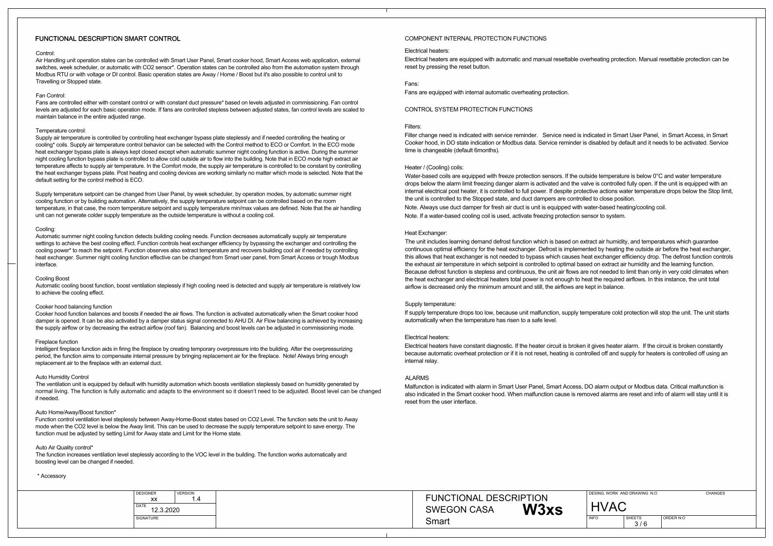
FUNCTIONAL DESCRIPTION SMART CONTROL
Control:Air Handling unit operation states can be controlled with Smart User Panel, Smart cooker hood, Smart Access web application, external switches, week scheduler, or automatic with CO2 sensor*. Operation states can be controlled also from automation system through Modbus RTU or with voltage or DI control. Basic operation states are Away / Home / Boost but it's also possible to control unit to Travelling or Stopped state.
Fan Control:Fans are controlled either with constant control or with constant duct pressure* based on levels adjusted in commissioning. Fan control levels are adjusted for each basic operation mode. If fans are controlled steplessly between adjusted states, fan control levels are scaled to maintain balance in entire adjusted range.
Temperature control:Supply temperature is controlled by controlling post heater in heating period. During summer period supply temperature is controlled by controlling heat exchanger efficiency and by controlling cooling coil power*. Supply temperature setpoint can be changed from User Panel, by week scheduler, by operation modes, by automatic summer night cooling function or by building automation. Alternatively supply temperature setpoint can be controlled based on room temperature, in that case room temperature setpoint and supply temperature min/max values are defined.
Cooling:Automatic summer night cooling function detects building cooling need. Function decreases automatically supply air temperature settings in order to achieve best cooling effect. Function controls heat exchanger efficiency with bypassing the exchanger and cooling power* to reach the setpoint. Function observes also extract temperature and recovers building cool air if needed by controlling heat exchanger. Summer night cooling function effective can be changed from Smart user panel, from Smart Access or trough modbus interface. Cooling BoostAutomatic cooling boost function, boost ventilation steplessly if high cooling need is detected and supply air temperature is relatively low to achieve cooling effect.
Cooker hood balancing functionCooker hood function balances and boosts if needed the air flows. Function is activated automatically when Smart cooker hood damper is opened. It can be also activated by damper status signal connected to AHU DI. Air Flow balancing is achieved by increasing the supply airflow or by decreasing the extract airflow (roof fan). Balancing and boost levels can be adjusted in commissioning mode.
Fireplace functionIntelligent fireplace function aids firing the fireplace by creating temporary overpressure into building. After overpressurizing period, the function aims to compensate internal pressure by bringing replacement air for fireplace. Note! Always bring enough replacement air to fireplace with external duct. Auto Humidity Control Ventilation unit is equipped by default with humidity automation which boost ventilation steplessly based on humidity
Boost level can be changed if needed.
Auto Home/Away/Boost function*Function control ventilation level steplessly between Away-Home-Boost states based on CO2 Level. Function sets unit also to Away CO2 level is below Away limit which can i.e. decrease supply temperature setpoint in order to save energy. Function must be adjusted by setting Limit for Away state and for Home state.
Auto Air Quality control*Function increases ventilation level steplessly according to the VOC level in the building. Function works automatically and boosting level can be changed if needed.
* Accessory
DESIGNER VERSION
DATE
SIGNATURE
DESING, WORK AND DRAWING N:O
INFO SHEETS ORDER N:O
CHANGESxx 1.4
12.3.2020
FUNCTIONAL DESCRIPTIONSWEGON CASA Smart 3 / 6
HVAC
COMPONENT INTERNAL PROTECTION FUNCTIONS
Electrical heaters:Electrical heaters are equipped with automatic and manual resettable overheating protection. Manual resettable protection can be reset by pressing reset button .
Fans:Fans are equipped with internal automatic overheating protection.
CONTROL SYSTEM PROTECTION FUCNTIONS
Filters:Filter change need is indicated with service reminder. Service need is indicated in Smart User Panel, in Smart Access, in Smart Cooker hood, in DO state indication or in modbus data. Service reminder is disabled by default and it needs to be activated. Service time is changeable (default 6months).
Heater / (Cooling) coils:Water based coils are equipped with freeze protection sensor. If outside temperature is below 0C and water temperature drops below alarm limit freezing danger alarm is activated and actuator is controlled fully open. If unit is equipped with internal electrical post heater, it is controlled to full power. If despite protective actions water temperature drops below Stop limit, the unit is controlled to Stopped state, and duct dampers are controlled to close position. Note. Always use duct damper for fresh air duct is unit is equipped with water-based heating / cooling coil.Note. If water based cooling coil is used, activate freezing protection sensor to system.
Heat Exchanger:Unit includes automatic defrost function based on temperatures. Defrost function guarantees heat exchanger continuous and reliable operation. Defrost is executed by heating fresh air and by limiting fan speeds. Because heat exchanger is never bypassed in cold climate, supply air temperate will stay in safe level even in extreme cold conditions.
Supply temperatur:If supply temperature drops too low, because unit malfunction, supply temperature cold protection will stop the unit. Unit starts automatically when temperature has risen to safe level.
Electrical heaters:Electrical heaters have constant diagnostic. If heater circuit is broken it gives heater alarm. If circuit is broken constantly because automatic overheat protection or if it is not reset, heating is controlled off and supply for heaters are controlled off by means of internal relay.
ALARMSMalfunction is indicated with alarm in Smart User Panel, Smart Access, DO alarm output or modbus data. Critical malfunction is also indicated in Smart cooker hood. When malfunction cause is removed alarms is reset and info of alarm will stay until it is reset from user interface.
FUNCTIONAL DESCRIPTION SMART CONTROL
Control:Air Handling unit operation states can be controlled with Smart User Panel, Smart cooker hood, Smart Access web application, external switches, week scheduler, or automatic with CO2 sensor*. Operation states can be controlled also from automation system through Modbus RTU or with voltage or DI control. Basic operation states are Away / Home / Boost but it's also possible to control unit to Travelling or Stopped state.
Fan Control:Fans are controlled either with constant control or with constant duct pressure* based on levels adjusted in commissioning. Fan control levels are adjusted for each basic operation mode. If fans are controlled steplessly between adjusted states, fan control levels are scaled to maintain balance in entire adjusted range.
Temperature control:Supply temperature is controlled by controlling post heater in heating period. During summer period supply temperature is controlled by controlling heat exchanger efficiency and by controlling cooling coil power*. Supply temperature setpoint can be changed from User Panel, by week scheduler, by operation modes, by automatic summer night cooling function or by building automation. Alternatively supply temperature setpoint can be controlled based on room temperature, in that case room temperature setpoint and supply temperature min/max values are defined.
Cooling:Automatic summer night cooling function detects building cooling need. Function decreases automatically supply air temperature settings in order to achieve best cooling effect. Function controls heat exchanger efficiency with bypassing the exchanger and cooling power* to reach the setpoint. Function observes also extract temperature and recovers building cool air if needed by controlling heat exchanger. Summer night cooling function effective can be changed from Smart user panel, from Smart Access or trough modbus interface. Cooling BoostAutomatic cooling boost function, boost ventilation steplessly if high cooling need is detected and supply air temperature is relatively low to achieve cooling effect.
Cooker hood balancing functionCooker hood function balances and boosts if needed the air flows. Function is activated automatically when Smart cooker hood damper is opened. It can be also activated by damper status signal connected to AHU DI. Air Flow balancing is achieved by increasing the supply airflow or by decreasing the extract airflow (roof fan). Balancing and boost levels can be adjusted in commissioning mode.
Fireplace functionIntelligent fireplace function aids firing the fireplace by creating temporary overpressure into building. After overpressurizing period, the function aims to compensate internal pressure by bringing replacement air for fireplace. Note! Always bring enough replacement air to fireplace with external duct. Auto Humidity Control Ventilation unit is equipped by default with humidity automation which boost ventilation steplessly based on humidity
Boost level can be changed if needed.
Auto Home/Away/Boost function*Function control ventilation level steplessly between Away-Home-Boost states based on CO2 Level. Function sets unit also to Away CO2 level is below Away limit which can i.e. decrease supply temperature setpoint in order to save energy. Function must be adjusted by setting Limit for Away state and for Home state.
Auto Air Quality control*Function increases ventilation level steplessly according to the VOC level in the building. Function works automatically and boosting level can be changed if needed.
* Accessory
COMPONENT INTERNAL PROTECTION FUNCTIONS
Electrical heaters:Electrical heaters are equipped with automatic and manual resettable overheating protection. Manual resettable protection can be reset by pressing reset button .
Fans:Fans are equipped with internal automatic overheating protection.
CONTROL SYSTEM PROTECTION FUCNTIONS Filters:Filter change need is indicated with service reminder. Service need is indicated in Smart User Panel, in Smart Access, in Smart Cooker hood, in DO state indication or in modbus data. Service reminder is disabled by default and it needs to be activated. Service time is changeable (default 6months).
Heater / (Cooling) coils:Water based coils are equipped with freeze protection sensor. If outside temperature is below 0C and water temperature drops below alarm limit freezing danger alarm is activated and actuator is controlled fully open. If unit is equipped with internal electrical post heater, it is controlled to full power. If despite protective actions water temperature drops below Stop limit, the unit is controlled to Stopped state, and duct dampers are controlled to close position. Note. Always use duct damper for fresh air duct is unit is equipped with water-based heating / cooling coil.Note. If water based cooling coil is used, activate freezing protection sensor to system.
Heat Exchanger:Unit included automatic demand defrost based on temperatures and extract air humidity. Defrost function guarantees heat exchanger continuous and reliable operation always with high efficiency. Defrost is executed by heating fresh air steplessly on demand and by limiting fan speeds on demand in very cold climates. Because heat exchanger is never bypassed in cold climate, supply air temperate will stay in safe level even in extreme cold conditions.
Supply temperature:If supply temperature drops too low, because unit malfunction, supply temperature cold protection will stop the unit. Unit starts automatically when temperature has risen to safe level.
Electrical heaters:Electrical heaters have constant diagnostic. If heater circuit is broken it gives heater alarm. If circuit is broken constantly because automatic overheat protection or if it is not reset, heating is controlled off and supply for heaters are controlled off by means of internal relay.
ALARMSMalfunction is indicated with alarm in Smart User Panel, Smart Access, DO alarm output or modbus data. Critical malfunction is also indicated in Smart cooker hood. When malfunction cause is removed alarms is reset and info of alarm will stay until it is reset from user interface.
W3W3 EconoW4W5
FUNCTIONAL DESCRIPTION SMART CONTROL
Control:Air Handling unit operation states can be controlled with Smart User Panel, Smart cooker hood, Smart Access web application, external switches, week scheduler, or automatic with CO2 sensor*. Operation states can be controlled also from automation system through Modbus RTU or with voltage or DI control. Basic operation states are Away / Home / Boost but it's also possible to control unit to Travelling or Stopped state.
Fan Control:Fans are controlled either with constant control or with constant duct pressure* based on levels adjusted in commissioning. Fan control levels are adjusted for each basic operation mode. If fans are controlled steplessly between adjusted states, fan control levels are scaled to maintain balance in entire adjusted range.
Temperature control:Supply temperature is controlled by controlling post heater in heating period. During summer period supply temperature is controlled by controlling heat exchanger efficiency and by controlling cooling coil power*. Supply temperature setpoint can be changed from User Panel, by week scheduler, by operation modes, by automatic summer night cooling function or by building automation. Alternatively supply temperature setpoint can be controlled based on room temperature, in that case room temperature setpoint and supply temperature min/max values are defined.
Cooling:Automatic summer night cooling function detects building cooling need. Function decreases automatically supply air temperature settings in order to achieve best cooling effect. Function controls heat exchanger efficiency with bypassing the exchanger and cooling power* to reach the setpoint. Function observes also extract temperature and recovers building cool air if needed by controlling heat exchanger. Summer night cooling function effective can be changed from Smart user panel, from Smart Access or trough modbus interface. Cooling BoostAutomatic cooling boost function, boost ventilation steplessly if high cooling need is detected and supply air temperature is relatively low to achieve cooling effect.
Cooker hood balancing functionCooker hood function balances and boosts if needed the air flows. Function is activated automatically when Smart cooker hood damper is opened. It can be also activated by damper status signal connected to AHU DI. Air Flow balancing is achieved by increasing the supply airflow or by decreasing the extract airflow (roof fan). Balancing and boost levels can be adjusted in commissioning mode.
Fireplace functionIntelligent fireplace function aids firing the fireplace by creating temporary overpressure into building. After overpressurizing period, the function aims to compensate internal pressure by bringing replacement air for fireplace. Note! Always bring enough replacement air to fireplace with external duct. Auto Humidity Control Ventilation unit is equipped by default with humidity automation which boost ventilation steplessly based on humidity
Boost level can be changed if needed.
Auto Home/Away/Boost function*Function control ventilation level steplessly between Away-Home-Boost states based on CO2 Level. Function sets unit also to Away CO2 level is below Away limit which can i.e. decrease supply temperature setpoint in order to save energy. Function must be adjusted by setting Limit for Away state and for Home state.
Auto Air Quality control*Function increases ventilation level steplessly according to the VOC level in the building. Function works automatically and boosting level can be changed if needed.
* Accessory
COMPONENT INTERNAL PROTECTION FUNCTIONS
Electrical heaters:Electrical heaters are equipped with automatic and manual resettable overheating protection. Manual resettable protection can be reset by pressing reset button .
Fans:Fans are equipped with internal automatic overheating protection.
CONTROL SYSTEM PROTECTION FUCNTIONS
Filters:Filter change need is indicated with service reminder. Service need is indicated in Smart User Panel, in Smart Access, in Smart Cooker hood, in DO state indication or in modbus data. Service reminder is disabled by default and it needs to be activated. Service time is changeable (default 6months).
Heater / (Cooling) coils:Water based coils are equipped with freeze protection sensor. If outside temperature is below 0C and water temperature drops below alarm limit freezing danger alarm is activated and actuator is controlled fully open. If unit is equipped with internal electrical post heater, it is controlled to full power. If despite protective actions water temperature drops below Stop limit, the unit is controlled to Stopped state, and duct dampers are controlled to close position. Note. Always use duct damper for fresh air duct is unit is equipped with water-based heating / cooling coil.Note. If water based cooling coil is used, activate freezing protection sensor to system.
Heat Exchanger:Unit includes automatic defrost function based on temperatures. Defrost function guarantees heat exchanger continuous and reliable operation. Defrost is executed by heating fresh air and by limiting fan speeds. Because heat exchanger is never bypassed in cold climate, supply air temperate will stay in safe level even in extreme cold conditions.
Supply temperatur:If supply temperature drops too low, because unit malfunction, supply temperature cold protection will stop the unit. Unit starts automatically when temperature has risen to safe level.
Electrical heaters:Electrical heaters have constant diagnostic. If heater circuit is broken it gives heater alarm. If circuit is broken constantly because automatic overheat protection or if it is not reset, heating is controlled off and supply for heaters are controlled off by means of internal relay.
ALARMSMalfunction is indicated with alarm in Smart User Panel, Smart Access, DO alarm output or modbus data. Critical malfunction is also indicated in Smart cooker hood. When malfunction cause is removed alarms is reset and info of alarm will stay until it is reset from user interface.
W9W9 Econo
FUNCTIONAL DESCRIPTION SMART CONTROL
Control:Air Handling unit operation states can be controlled with Smart User Panel, Smart cooker hood, Smart Access web application, external switches, week scheduler, or automatic with CO2 sensor*. Operation states can be controlled also from automation system through Modbus RTU or with voltage or DI control. Basic operation states are Away / Home / Boost but it's also possible to control unit to Travelling or Stopped state.
Fan Control:Fans are controlled either with constant control or with constant duct pressure* based on levels adjusted in commissioning. Fan control levels are adjusted for each basic operation mode. If fans are controlled steplessly between adjusted states, fan control levels are scaled to maintain balance in entire adjusted range.
Temperature control:Air Handling Unit is equipped with efficiency controlled rotating heat exchange (Rotor). Rotor is controlled either to maintain constant supply temperature (Comfort mode) or to achieve maximal energy efficiency (ECO mode). Supply temperature is controlled also with postheater during heating period and with cooling coil* during summer.Supply temperature setpoint can be changed from User Panel, by week scheduler, by operation modes, by automatic summer night cooling function or by building automation. Alternatively supply temperature setpoint can be controlled based on room temperature, in that case room temperature setpoint and supply temperature min/max values are defined.
Cooling:Automatic summer night cooling function detects building cooling need. Function decreases automatically supply air temperature settings in order to achieve best cooling effect. Function controls heat exchanger efficiency with bypassing the exchanger and cooling power* to reach the setpoint. Function observes also extract temperature and recovers building cool air if needed by controlling heat exchanger. Summer night cooling function effective can be changed from Smart user panel, from Smart Access or trough modbus interface. Cooling BoostAutomatic cooling boost function, boost ventilation steplessly if high cooling need is detected and supply air temperature is relatively low to achieve cooling effect.
Cooker hood balancing functionCooker hood function balances and boosts if needed the air flows. Function is activated automatically when Smart cooker hood damper is opened. It can be also activated by damper status signal connected to AHU DI. Air Flow balancing is achieved by increasing the supply airflow or by decreasing the extract airflow (roof fan). Balancing and boost levels can be adjusted in commissioning mode.
Fireplace functionIntelligent fireplace function aids firing the fireplace by creating temporary overpressure into building. After overpressurizing period, the function aims to compensate internal pressure by bringing replacement air for fireplace. Note! Always bring enough replacement air to fireplace with external duct. Auto Humidity Control Ventilation unit is equipped by default with humidity automation which boost ventilation steplessly based on humidity
Boost level can be changed if needed.
Auto Home/Away/Boost function*Function control ventilation level steplessly between Away-Home-Boost states based on CO2 Level. Function sets unit also to Away CO2 level is below Away limit which can i.e. decrease supply temperature setpoint in order to save energy. Function must be adjusted by setting Limit for Away state and for Home state.
Auto Air Quality control*Function increases ventilation level steplessly according to the VOC level in the building. Function works automatically and boosting level can be changed if needed.
* Accessory
COMPONENT INTERNAL PROTECTION FUNCTIONS
Electrical heaters:Electrical heaters are equipped with automatic and manual resettable overheating protection. Manual resettable protection can be reset by pressing reset button .
Fans:Fans are equipped with internal automatic overheating protection.
CONTROL SYSTEM PROTECTION FUCNTIONS
Filters:Filter change need is indicated with service reminder. Service need is indicated in Smart User Panel, in Smart Access, in Smart Cooker hood, in DO state indication or in modbus data. Service reminder is disabled by default and it needs to be activated. Service time is changeable (default 6months).
Heater / (Cooling) coils:Water based coils are equipped with freeze protection sensor. If outside temperature is below 0C and water temperature drops below alarm limit freezing danger alarm is activated and actuator is controlled fully open. If unit is equipped with internal electrical post heater, it is controlled to full power. If despite protective actions water temperature drops below Stop limit, the unit is controlled to Stopped state, and duct dampers are controlled to close position. Note. Always use duct damper for fresh air duct is unit is equipped with water-based heating / cooling coil.Note. If water based cooling coil is used, activate freezing protection sensor to system.
Heat Exchanger:Unit included automatic stepless defrost based on temperatures. Defrost function guarantees heat exchanger continuous and reliable operation. Defrost is executed by limiting fan speeds steplessly. Because heat exchanger is controlled always in best efficiency in cold climate, supply air temperate will stay in safe level even in extreme cold conditions. Balanced air flow in all climates can be guaranteed by using correct rated duct mounted preheater sold as accessory by Swegon.
Supply temperatur:If supply temperature drops too low, because unit malfunction, supply temperature cold protection will stop the unit. Unit starts automatically when temperature has risen to safe level.
Electrical heaters:Electrical heaters have constant diagnostic. If heater circuit is broken it gives heater alarm. If circuit is broken constantly because automatic overheat protection or if it is not reset, heating is controlled off and supply for heaters are controlled off by means of internal relay.
ALARMSMalfunction is indicated with alarm in Smart User Panel, Smart Access, DO alarm output or modbus data. Critical malfunction is also indicated in Smart cooker hood. When malfunction cause is removed alarms is reset and info of alarm will stay until it is reset from user interface.
R3
FUNCTIONAL DESCRIPTION SMART CONTROL
Control:Air Handling unit operation states can be controlled with Smart User Panel, Smart cooker hood, Smart Access web application, external switches, week scheduler, or automatic with CO2 sensor*. Operation states can be controlled also from automation system through Modbus RTU or with voltage or DI control. Basic operation states are Away / Home / Boost but it's also possible to control unit to Travelling or Stopped state.
Fan Control:Fans are controlled either with constant control or with constant duct pressure* based on levels adjusted in commissioning. Fan control levels are adjusted for each basic operation mode. If fans are controlled steplessly between adjusted states, fan control levels are scaled to maintain balance in entire adjusted range.
Temperature control:Air Handling Unit is equipped with efficiency controlled rotating heat exchange (Rotor). Rotor is controlled either to maintain constant supply temperature (Comfort mode) or to achieve maximal energy efficiency (ECO mode). Supply temperature is controlled also with postheater during heating period and with cooling coil* during summer.Supply temperature setpoint can be changed from User Panel, by week scheduler, by operation modes, by automatic summer night cooling function or by building automation. Alternatively supply temperature setpoint can be controlled based on room temperature, in that case room temperature setpoint and supply temperature min/max values are defined.
Cooling:Automatic summer night cooling function detects building cooling need. Function decreases automatically supply air temperature settings in order to achieve best cooling effect. Function controls heat exchanger efficiency with bypassing the exchanger and cooling power* to reach the setpoint. Function observes also extract temperature and recovers building cool air if needed by controlling heat exchanger. Summer night cooling function effective can be changed from Smart user panel, from Smart Access or trough modbus interface. Cooling BoostAutomatic cooling boost function, boost ventilation steplessly if high cooling need is detected and supply air temperature is relatively low to achieve cooling effect.
Cooker hood balancing functionCooker hood function balances and boosts if needed the air flows. Function is activated automatically when Smart cooker hood damper is opened. It can be also activated by damper status signal connected to AHU DI. Air Flow balancing is achieved by increasing the supply airflow or by decreasing the extract airflow (roof fan). Balancing and boost levels can be adjusted in commissioning mode.
Fireplace functionIntelligent fireplace function aids firing the fireplace by creating temporary overpressure into building. After overpressurizing period, the function aims to compensate internal pressure by bringing replacement air for fireplace. Note! Always bring enough replacement air to fireplace with external duct. Auto Humidity Control Ventilation unit is equipped by default with humidity automation which boost ventilation steplessly based on humidity
Boost level can be changed if needed.
Auto Home/Away/Boost function*Function control ventilation level steplessly between Away-Home-Boost states based on CO2 Level. Function sets unit also to Away CO2 level is below Away limit which can i.e. decrease supply temperature setpoint in order to save energy. Function must be adjusted by setting Limit for Away state and for Home state.
Auto Air Quality control*Function increases ventilation level steplessly according to the VOC level in the building. Function works automatically and boosting level can be changed if needed.
* Accessory
COMPONENT INTERNAL PROTECTION FUNCTIONS
Electrical heaters:Electrical heaters are equipped with automatic and manual resettable overheating protection. Manual resettable protection can be reset by pressing reset button .
Fans:Fans are equipped with internal automatic overheating protection.
CONTROL SYSTEM PROTECTION FUCNTIONS
Filters:Filter change need is indicated with service reminder. Service need is indicated in Smart User Panel, in Smart Access, in Smart Cooker hood, in DO state indication or in modbus data. Service reminder is disabled by default and it needs to be activated. Service time is changeable (default 6months).
Heater / (Cooling) coils:Water based coils are equipped with freeze protection sensor. If outside temperature is below 0C and water temperature drops below alarm limit freezing danger alarm is activated and actuator is controlled fully open. If unit is equipped with internal electrical post heater, it is controlled to full power. If despite protective actions water temperature drops below Stop limit, the unit is controlled to Stopped state, and duct dampers are controlled to close position. Note. Always use duct damper for fresh air duct is unit is equipped with water-based heating / cooling coil.Note. If water based cooling coil is used, activate freezing protection sensor to system.
Heat Exchanger:Unit included automatic stepless defrost based on temperatures. Defrost function guarantees heat exchanger continuous and reliable operation. Defrost is executed by limiting fan speeds steplessly. Because heat exchanger is controlled always in best efficiency in cold climate, supply air temperate will stay in safe level even in extreme cold conditions. Balanced air flow in all climates can be guaranteed by using correct rated duct mounted preheater sold as accessory by Swegon.
Supply temperatur:If supply temperature drops too low, because unit malfunction, supply temperature cold protection will stop the unit. Unit starts automatically when temperature has risen to safe level.
Electrical heaters:Electrical heaters have constant diagnostic. If heater circuit is broken it gives heater alarm. If circuit is broken constantly because automatic overheat protection or if it is not reset, heating is controlled off and supply for heaters are controlled off by means of internal relay.
ALARMSMalfunction is indicated with alarm in Smart User Panel, Smart Access, DO alarm output or modbus data. Critical malfunction is also indicated in Smart cooker hood. When malfunction cause is removed alarms is reset and info of alarm will stay until it is reset from user interface.
R5-H
FUNCTIONAL DESCRIPTION SMART CONTROL
Control:Air Handling unit operation states can be controlled with Smart User Panel, Smart cooker hood, Smart Access web application, external switches, week scheduler, or automatic with CO2 sensor*. Operation states can be controlled also from automation system through Modbus RTU or with voltage or DI control. Basic operation states are Away / Home / Boost but it's also possible to control unit to Travelling or Stopped state.
Fan Control:Fans are controlled either with constant control or with constant duct pressure* based on levels adjusted in commissioning. Fan control levels are adjusted for each basic operation mode. If fans are controlled steplessly between adjusted states, fan control levels are scaled to maintain balance in entire adjusted range.
Temperature control:Air Handling Unit is equipped with efficiency controlled rotating heat exchange (Rotor). Rotor is controlled either to maintain constant supply temperature (Comfort mode) or to achieve maximal energy efficiency (ECO mode). Supply temperature is controlled also with postheater during heating period and with cooling coil* during summer.Supply temperature setpoint can be changed from User Panel, by week scheduler, by operation modes, by automatic summer night cooling function or by building automation. Alternatively supply temperature setpoint can be controlled based on room temperature, in that case room temperature setpoint and supply temperature min/max values are defined.
Cooling:Automatic summer night cooling function detects building cooling need. Function decreases automatically supply air temperature settings in order to achieve best cooling effect. Function controls heat exchanger efficiency with bypassing the exchanger and cooling power* to reach the setpoint. Function observes also extract temperature and recovers building cool air if needed by controlling heat exchanger. Summer night cooling function effective can be changed from Smart user panel, from Smart Access or trough modbus interface. Cooling BoostAutomatic cooling boost function, boost ventilation steplessly if high cooling need is detected and supply air temperature is relatively low to achieve cooling effect.
Cooker hood balancing functionCooker hood function balances and boosts if needed the air flows. Function is activated automatically when Smart cooker hood damper is opened. It can be also activated by damper status signal connected to AHU DI. Air Flow balancing is achieved by increasing the supply airflow or by decreasing the extract airflow (roof fan). Balancing and boost levels can be adjusted in commissioning mode.
Fireplace functionIntelligent fireplace function aids firing the fireplace by creating temporary overpressure into building. After overpressurizing period, the function aims to compensate internal pressure by bringing replacement air for fireplace. Note! Always bring enough replacement air to fireplace with external duct. Auto Humidity Control Ventilation unit is equipped by default with humidity automation which boost ventilation steplessly based on humidity
Boost level can be changed if needed.
Auto Home/Away/Boost function*Function control ventilation level steplessly between Away-Home-Boost states based on CO2 Level. Function sets unit also to Away CO2 level is below Away limit which can i.e. decrease supply temperature setpoint in order to save energy. Function must be adjusted by setting Limit for Away state and for Home state.
Auto Air Quality control*Function increases ventilation level steplessly according to the VOC level in the building. Function works automatically and boosting level can be changed if needed.
* Accessory
COMPONENT INTERNAL PROTECTION FUNCTIONS
Electrical heaters:Electrical heaters are equipped with automatic and manual resettable overheating protection. Manual resettable protection can be reset by pressing reset button .
Fans:Fans are equipped with internal automatic overheating protection.
CONTROL SYSTEM PROTECTION FUCNTIONS
Filters:Filter change need is indicated with service reminder. Service need is indicated in Smart User Panel, in Smart Access, in Smart Cooker hood, in DO state indication or in modbus data. Service reminder is disabled by default and it needs to be activated. Service time is changeable (default 6months).
Heater / (Cooling) coils:Water based coils are equipped with freeze protection sensor. If outside temperature is below 0C and water temperature drops below alarm limit freezing danger alarm is activated and actuator is controlled fully open. If unit is equipped with internal electrical post heater, it is controlled to full power. If despite protective actions water temperature drops below Stop limit, the unit is controlled to Stopped state, and duct dampers are controlled to close position. Note. Always use duct damper for fresh air duct is unit is equipped with water-based heating / cooling coil.Note. If water based cooling coil is used, activate freezing protection sensor to system.
Heat Exchanger:Unit included automatic stepless defrost based on temperatures. Defrost function guarantees heat exchanger continuous and reliable operation. Defrost is executed by limiting fan speeds steplessly. Because heat exchanger is controlled always in best efficiency in cold climate, supply air temperate will stay in safe level even in extreme cold conditions. Balanced air flow in all climates can be guaranteed by using correct rated duct mounted preheater sold as accessory by Swegon.
Supply temperatur:If supply temperature drops too low, because unit malfunction, supply temperature cold protection will stop the unit. Unit starts automatically when temperature has risen to safe level.
Electrical heaters:Electrical heaters have constant diagnostic. If heater circuit is broken it gives heater alarm. If circuit is broken constantly because automatic overheat protection or if it is not reset, heating is controlled off and supply for heaters are controlled off by means of internal relay.
ALARMSMalfunction is indicated with alarm in Smart User Panel, Smart Access, DO alarm output or modbus data. Critical malfunction is also indicated in Smart cooker hood. When malfunction cause is removed alarms is reset and info of alarm will stay until it is reset from user interface.
R2
FUNCTIONAL DESCRIPTION SMART CONTROL
Control:Air Handling unit operation states can be controlled with Smart User Panel, Smart cooker hood, Smart Access web application, external switches, week scheduler, or automatic with CO2 sensor*. Operation states can be controlled also from automation system through Modbus RTU or with voltage or DI control. Basic operation states are Away / Home / Boost but it's also possible to control unit to Travelling or Stopped state.
Fan Control:Fans are controlled either with constant control or with constant duct pressure* based on levels adjusted in commissioning. Fan control levels are adjusted for each basic operation mode. If fans are controlled steplessly between adjusted states, fan control levels are scaled to maintain balance in entire adjusted range.
Temperature control:Air Handling Unit is equipped with efficiency controlled rotating heat exchange (Rotor). Rotor is controlled either to maintain constant supply temperature (Comfort mode) or to achieve maximal energy efficiency (ECO mode). Supply temperature is controlled also with postheater during heating period and with cooling coil* during summer.Supply temperature setpoint can be changed from User Panel, by week scheduler, by operation modes, by automatic summer night cooling function or by building automation. Alternatively supply temperature setpoint can be controlled based on room temperature, in that case room temperature setpoint and supply temperature min/max values are defined.
Cooling:Automatic summer night cooling function detects building cooling need. Function decreases automatically supply air temperature settings in order to achieve best cooling effect. Function controls heat exchanger efficiency with bypassing the exchanger and cooling power* to reach the setpoint. Function observes also extract temperature and recovers building cool air if needed by controlling heat exchanger. Summer night cooling function effective can be changed from Smart user panel, from Smart Access or trough modbus interface. Cooling BoostAutomatic cooling boost function, boost ventilation steplessly if high cooling need is detected and supply air temperature is relatively low to achieve cooling effect.
Cooker hood balancing functionCooker hood function balances and boosts if needed the air flows. Function is activated automatically when Smart cooker hood damper is opened. It can be also activated by damper status signal connected to AHU DI. Air Flow balancing is achieved by increasing the supply airflow or by decreasing the extract airflow (roof fan). Balancing and boost levels can be adjusted in commissioning mode.
Fireplace functionIntelligent fireplace function aids firing the fireplace by creating temporary overpressure into building. After overpressurizing period, the function aims to compensate internal pressure by bringing replacement air for fireplace. Note! Always bring enough replacement air to fireplace with external duct. Auto Humidity Control Ventilation unit is equipped by default with humidity automation which boost ventilation steplessly based on humidity
Boost level can be changed if needed.
Auto Home/Away/Boost function*Function control ventilation level steplessly between Away-Home-Boost states based on CO2 Level. Function sets unit also to Away CO2 level is below Away limit which can i.e. decrease supply temperature setpoint in order to save energy. Function must be adjusted by setting Limit for Away state and for Home state.
Auto Air Quality control*Function increases ventilation level steplessly according to the VOC level in the building. Function works automatically and boosting level can be changed if needed.
* Accessory
COMPONENT INTERNAL PROTECTION FUNCTIONS
Electrical heaters:Electrical heaters are equipped with automatic and manual resettable overheating protection. Manual resettable protection can be reset by pressing reset button .
Fans:Fans are equipped with internal automatic overheating protection.
CONTROL SYSTEM PROTECTION FUCNTIONS
Filters:Filter change need is indicated with service reminder. Service need is indicated in Smart User Panel, in Smart Access, in Smart Cooker hood, in DO state indication or in modbus data. Service reminder is disabled by default and it needs to be activated. Service time is changeable (default 6months).
Heater / (Cooling) coils:Water based coils are equipped with freeze protection sensor. If outside temperature is below 0C and water temperature drops below alarm limit freezing danger alarm is activated and actuator is controlled fully open. If unit is equipped with internal electrical post heater, it is controlled to full power. If despite protective actions water temperature drops below Stop limit, the unit is controlled to Stopped state, and duct dampers are controlled to close position. Note. Always use duct damper for fresh air duct is unit is equipped with water-based heating / cooling coil.Note. If water based cooling coil is used, activate freezing protection sensor to system.
Heat Exchanger:Unit included automatic stepless defrost based on temperatures. Defrost function guarantees heat exchanger continuous and reliable operation. Defrost is executed by limiting fan speeds steplessly. Because heat exchanger is controlled always in best efficiency in cold climate, supply air temperate will stay in safe level even in extreme cold conditions. Balanced air flow in all climates can be guaranteed by using correct rated duct mounted preheater sold as accessory by Swegon.
Supply temperatur:If supply temperature drops too low, because unit malfunction, supply temperature cold protection will stop the unit. Unit starts automatically when temperature has risen to safe level.
Electrical heaters:Electrical heaters have constant diagnostic. If heater circuit is broken it gives heater alarm. If circuit is broken constantly because automatic overheat protection or if it is not reset, heating is controlled off and supply for heaters are controlled off by means of internal relay.
ALARMSMalfunction is indicated with alarm in Smart User Panel, Smart Access, DO alarm output or modbus data. Critical malfunction is also indicated in Smart cooker hood. When malfunction cause is removed alarms is reset and info of alarm will stay until it is reset from user interface.
R5
FUNCTIONAL DESCRIPTION SMART CONTROL
Control:Air Handling unit operation states can be controlled with Smart User Panel, Smart cooker hood, Smart Access web application, external switches, week scheduler, or automatic with CO2 sensor*. Operation states can be controlled also from automation system through Modbus RTU or with voltage or DI control. Basic operation states are Away / Home / Boost but it's also possible to control unit to Travelling or Stopped state.
Fan Control:Fans are controlled either with constant control or with constant duct pressure* based on levels adjusted in commissioning. Fan control levels are adjusted for each basic operation mode. If fans are controlled steplessly between adjusted states, fan control levels are scaled to maintain balance in entire adjusted range.
Temperature control:Air Handling Unit is equipped with efficiency controlled rotating heat exchange (Rotor). Rotor is controlled either to maintain constant supply temperature (Comfort mode) or to achieve maximal energy efficiency (ECO mode). Supply temperature is controlled also with postheater during heating period and with cooling coil* during summer.Supply temperature setpoint can be changed from User Panel, by week scheduler, by operation modes, by automatic summer night cooling function or by building automation. Alternatively supply temperature setpoint can be controlled based on room temperature, in that case room temperature setpoint and supply temperature min/max values are defined.
Cooling:Automatic summer night cooling function detects building cooling need. Function decreases automatically supply air temperature settings in order to achieve best cooling effect. Function controls heat exchanger efficiency with bypassing the exchanger and cooling power* to reach the setpoint. Function observes also extract temperature and recovers building cool air if needed by controlling heat exchanger. Summer night cooling function effective can be changed from Smart user panel, from Smart Access or trough modbus interface. Cooling BoostAutomatic cooling boost function, boost ventilation steplessly if high cooling need is detected and supply air temperature is relatively low to achieve cooling effect.
Cooker hood balancing functionCooker hood function balances and boosts if needed the air flows. Function is activated automatically when Smart cooker hood damper is opened. It can be also activated by damper status signal connected to AHU DI. Air Flow balancing is achieved by increasing the supply airflow or by decreasing the extract airflow (roof fan). Balancing and boost levels can be adjusted in commissioning mode.
Fireplace functionIntelligent fireplace function aids firing the fireplace by creating temporary overpressure into building. After overpressurizing period, the function aims to compensate internal pressure by bringing replacement air for fireplace. Note! Always bring enough replacement air to fireplace with external duct. Auto Humidity Control Ventilation unit is equipped by default with humidity automation which boost ventilation steplessly based on humidity
Boost level can be changed if needed.
Auto Home/Away/Boost function*Function control ventilation level steplessly between Away-Home-Boost states based on CO2 Level. Function sets unit also to Away CO2 level is below Away limit which can i.e. decrease supply temperature setpoint in order to save energy. Function must be adjusted by setting Limit for Away state and for Home state.
Auto Air Quality control*Function increases ventilation level steplessly according to the VOC level in the building. Function works automatically and boosting level can be changed if needed.
* Accessory
COMPONENT INTERNAL PROTECTION FUNCTIONS
Electrical heaters:Electrical heaters are equipped with automatic and manual resettable overheating protection. Manual resettable protection can be reset by pressing reset button .
Fans:Fans are equipped with internal automatic overheating protection.
CONTROL SYSTEM PROTECTION FUCNTIONS
Filters:Filter change need is indicated with service reminder. Service need is indicated in Smart User Panel, in Smart Access, in Smart Cooker hood, in DO state indication or in modbus data. Service reminder is disabled by default and it needs to be activated. Service time is changeable (default 6months).
Heater / (Cooling) coils:Water based coils are equipped with freeze protection sensor. If outside temperature is below 0C and water temperature drops below alarm limit freezing danger alarm is activated and actuator is controlled fully open. If unit is equipped with internal electrical post heater, it is controlled to full power. If despite protective actions water temperature drops below Stop limit, the unit is controlled to Stopped state, and duct dampers are controlled to close position. Note. Always use duct damper for fresh air duct is unit is equipped with water-based heating / cooling coil.Note. If water based cooling coil is used, activate freezing protection sensor to system.
Heat Exchanger:Unit included automatic stepless defrost based on temperatures. Defrost function guarantees heat exchanger continuous and reliable operation. Defrost is executed by limiting fan speeds steplessly. Because heat exchanger is controlled always in best efficiency in cold climate, supply air temperate will stay in safe level even in extreme cold conditions. Balanced air flow in all climates can be guaranteed by using correct rated duct mounted preheater sold as accessory by Swegon.
Supply temperatur:If supply temperature drops too low, because unit malfunction, supply temperature cold protection will stop the unit. Unit starts automatically when temperature has risen to safe level.
Electrical heaters:Electrical heaters have constant diagnostic. If heater circuit is broken it gives heater alarm. If circuit is broken constantly because automatic overheat protection or if it is not reset, heating is controlled off and supply for heaters are controlled off by means of internal relay.
ALARMSMalfunction is indicated with alarm in Smart User Panel, Smart Access, DO alarm output or modbus data. Critical malfunction is also indicated in Smart cooker hood. When malfunction cause is removed alarms is reset and info of alarm will stay until it is reset from user interface.
R7/R7-H
FUNCTIONAL DESCRIPTION SMART CONTROL
Control:Air Handling unit operation states can be controlled with Smart User Panel, Smart cooker hood, Smart Access web application, external switches, week scheduler, or automatic with CO2 sensor*. Operation states can be controlled also from automation system through Modbus RTU or with voltage or DI control. Basic operation states are Away / Home / Boost but it's also possible to control unit to Travelling or Stopped state.
Fan Control:Fans are controlled either with constant control or with constant duct pressure* based on levels adjusted in commissioning. Fan control levels are adjusted for each basic operation mode. If fans are controlled steplessly between adjusted states, fan control levels are scaled to maintain balance in entire adjusted range.
Temperature control:Air Handling Unit is equipped with efficiency controlled rotating heat exchange (Rotor). Rotor is controlled either to maintain constant supply temperature (Comfort mode) or to achieve maximal energy efficiency (ECO mode). Supply temperature is controlled also with postheater during heating period and with cooling coil* during summer.Supply temperature setpoint can be changed from User Panel, by week scheduler, by operation modes, by automatic summer night cooling function or by building automation. Alternatively supply temperature setpoint can be controlled based on room temperature, in that case room temperature setpoint and supply temperature min/max values are defined.
Cooling:Automatic summer night cooling function detects building cooling need. Function decreases automatically supply air temperature settings in order to achieve best cooling effect. Function controls heat exchanger efficiency with bypassing the exchanger and cooling power* to reach the setpoint. Function observes also extract temperature and recovers building cool air if needed by controlling heat exchanger. Summer night cooling function effective can be changed from Smart user panel, from Smart Access or trough modbus interface. Cooling BoostAutomatic cooling boost function, boost ventilation steplessly if high cooling need is detected and supply air temperature is relatively low to achieve cooling effect.
Cooker hood balancing functionCooker hood function balances and boosts if needed the air flows. Function is activated automatically when Smart cooker hood damper is opened. It can be also activated by damper status signal connected to AHU DI. Air Flow balancing is achieved by increasing the supply airflow or by decreasing the extract airflow (roof fan). Balancing and boost levels can be adjusted in commissioning mode.
Fireplace functionIntelligent fireplace function aids firing the fireplace by creating temporary overpressure into building. After overpressurizing period, the function aims to compensate internal pressure by bringing replacement air for fireplace. Note! Always bring enough replacement air to fireplace with external duct. Auto Humidity Control Ventilation unit is equipped by default with humidity automation which boost ventilation steplessly based on humidity
Boost level can be changed if needed.
Auto Home/Away/Boost function*Function control ventilation level steplessly between Away-Home-Boost states based on CO2 Level. Function sets unit also to Away CO2 level is below Away limit which can i.e. decrease supply temperature setpoint in order to save energy. Function must be adjusted by setting Limit for Away state and for Home state.
Auto Air Quality control*Function increases ventilation level steplessly according to the VOC level in the building. Function works automatically and boosting level can be changed if needed.
* Accessory
COMPONENT INTERNAL PROTECTION FUNCTIONS
Electrical heaters:Electrical heaters are equipped with automatic and manual resettable overheating protection. Manual resettable protection can be reset by pressing reset button .
Fans:Fans are equipped with internal automatic overheating protection.
CONTROL SYSTEM PROTECTION FUCNTIONS
Filters:Filter change need is indicated with service reminder. Service need is indicated in Smart User Panel, in Smart Access, in Smart Cooker hood, in DO state indication or in modbus data. Service reminder is disabled by default and it needs to be activated. Service time is changeable (default 6months).
Heater / (Cooling) coils:Water based coils are equipped with freeze protection sensor. If outside temperature is below 0C and water temperature drops below alarm limit freezing danger alarm is activated and actuator is controlled fully open. If unit is equipped with internal electrical post heater, it is controlled to full power. If despite protective actions water temperature drops below Stop limit, the unit is controlled to Stopped state, and duct dampers are controlled to close position. Note. Always use duct damper for fresh air duct is unit is equipped with water-based heating / cooling coil.Note. If water based cooling coil is used, activate freezing protection sensor to system.
Heat Exchanger:Unit included automatic stepless defrost based on temperatures. Defrost function guarantees heat exchanger continuous and reliable operation. Defrost is executed by limiting fan speeds steplessly. Because heat exchanger is controlled always in best efficiency in cold climate, supply air temperate will stay in safe level even in extreme cold conditions. Balanced air flow in all climates can be guaranteed by using correct rated duct mounted preheater sold as accessory by Swegon.
Supply temperatur:If supply temperature drops too low, because unit malfunction, supply temperature cold protection will stop the unit. Unit starts automatically when temperature has risen to safe level.
Electrical heaters:Electrical heaters have constant diagnostic. If heater circuit is broken it gives heater alarm. If circuit is broken constantly because automatic overheat protection or if it is not reset, heating is controlled off and supply for heaters are controlled off by means of internal relay.
ALARMSMalfunction is indicated with alarm in Smart User Panel, Smart Access, DO alarm output or modbus data. Critical malfunction is also indicated in Smart cooker hood. When malfunction cause is removed alarms is reset and info of alarm will stay until it is reset from user interface.
R9/R9-H
FUNCTIONAL DESCRIPTION SMART CONTROL
Control:Air Handling unit operation states can be controlled with Smart User Panel, Smart cooker hood, Smart Access web application, external switches, week scheduler, or automatic with CO2 sensor*. Operation states can be controlled also from automation system through Modbus RTU or with voltage or DI control. Basic operation states are Away / Home / Boost but it's also possible to control unit to Travelling or Stopped state.
Fan Control:Fans are controlled either with constant control or with constant duct pressure* based on levels adjusted in commissioning. Fan control levels are adjusted for each basic operation mode. If fans are controlled steplessly between adjusted states, fan control levels are scaled to maintain balance in entire adjusted range.
Temperature control:Air Handling Unit is equipped with efficiency controlled rotating heat exchange (Rotor). Rotor is controlled either to maintain constant supply temperature (Comfort mode) or to achieve maximal energy efficiency (ECO mode). Supply temperature is controlled also with postheater during heating period and with cooling coil* during summer.Supply temperature setpoint can be changed from User Panel, by week scheduler, by operation modes, by automatic summer night cooling function or by building automation. Alternatively supply temperature setpoint can be controlled based on room temperature, in that case room temperature setpoint and supply temperature min/max values are defined.
Cooling:Automatic summer night cooling function detects building cooling need. Function decreases automatically supply air temperature settings in order to achieve best cooling effect. Function controls heat exchanger efficiency with bypassing the exchanger and cooling power* to reach the setpoint. Function observes also extract temperature and recovers building cool air if needed by controlling heat exchanger. Summer night cooling function effective can be changed from Smart user panel, from Smart Access or trough modbus interface. Cooling BoostAutomatic cooling boost function, boost ventilation steplessly if high cooling need is detected and supply air temperature is relatively low to achieve cooling effect.
Cooker hood balancing functionCooker hood function balances and boosts if needed the air flows. Function is activated automatically when Smart cooker hood damper is opened. It can be also activated by damper status signal connected to AHU DI. Air Flow balancing is achieved by increasing the supply airflow or by decreasing the extract airflow (roof fan). Balancing and boost levels can be adjusted in commissioning mode.
Fireplace functionIntelligent fireplace function aids firing the fireplace by creating temporary overpressure into building. After overpressurizing period, the function aims to compensate internal pressure by bringing replacement air for fireplace. Note! Always bring enough replacement air to fireplace with external duct. Auto Humidity Control Ventilation unit is equipped by default with humidity automation which boost ventilation steplessly based on humidity
Boost level can be changed if needed.
Auto Home/Away/Boost function*Function control ventilation level steplessly between Away-Home-Boost states based on CO2 Level. Function sets unit also to Away CO2 level is below Away limit which can i.e. decrease supply temperature setpoint in order to save energy. Function must be adjusted by setting Limit for Away state and for Home state.
Auto Air Quality control*Function increases ventilation level steplessly according to the VOC level in the building. Function works automatically and boosting level can be changed if needed.
* Accessory
COMPONENT INTERNAL PROTECTION FUNCTIONS
Electrical heaters:Electrical heaters are equipped with automatic and manual resettable overheating protection. Manual resettable protection can be reset by pressing reset button .
Fans:Fans are equipped with internal automatic overheating protection.
CONTROL SYSTEM PROTECTION FUCNTIONS
Filters:Filter change need is indicated with service reminder. Service need is indicated in Smart User Panel, in Smart Access, in Smart Cooker hood, in DO state indication or in modbus data. Service reminder is disabled by default and it needs to be activated. Service time is changeable (default 6months).
Heater / (Cooling) coils:Water based coils are equipped with freeze protection sensor. If outside temperature is below 0C and water temperature drops below alarm limit freezing danger alarm is activated and actuator is controlled fully open. If unit is equipped with internal electrical post heater, it is controlled to full power. If despite protective actions water temperature drops below Stop limit, the unit is controlled to Stopped state, and duct dampers are controlled to close position. Note. Always use duct damper for fresh air duct is unit is equipped with water-based heating / cooling coil.Note. If water based cooling coil is used, activate freezing protection sensor to system.
Heat Exchanger:Unit included automatic stepless defrost based on temperatures. Defrost function guarantees heat exchanger continuous and reliable operation. Defrost is executed by limiting fan speeds steplessly. Because heat exchanger is controlled always in best efficiency in cold climate, supply air temperate will stay in safe level even in extreme cold conditions. Balanced air flow in all climates can be guaranteed by using correct rated duct mounted preheater sold as accessory by Swegon.
Supply temperatur:If supply temperature drops too low, because unit malfunction, supply temperature cold protection will stop the unit. Unit starts automatically when temperature has risen to safe level.
Electrical heaters:Electrical heaters have constant diagnostic. If heater circuit is broken it gives heater alarm. If circuit is broken constantly because automatic overheat protection or if it is not reset, heating is controlled off and supply for heaters are controlled off by means of internal relay.
ALARMSMalfunction is indicated with alarm in Smart User Panel, Smart Access, DO alarm output or modbus data. Critical malfunction is also indicated in Smart cooker hood. When malfunction cause is removed alarms is reset and info of alarm will stay until it is reset from user interface.
R15/R15-H
FUNCTIONAL DESCRIPTION SMART CONTROL
Control:Air Handling unit operation states can be controlled with Smart User Panel, Smart cooker hood, Smart Access web application, external switches, week scheduler, or automatic with CO2 sensor*. Operation states can be controlled also from automation system through Modbus RTU or with voltage or DI control. Basic operation states are Away / Home / Boost but it's also possible to control unit to Travelling or Stopped state.
Fan Control:Fans are controlled either with constant control or with constant duct pressure* based on levels adjusted in commissioning. Fan control levels are adjusted for each basic operation mode. If fans are controlled steplessly between adjusted states, fan control levels are scaled to maintain balance in entire adjusted range.
Temperature control:Supply temperature is controlled by controlling post heater in heating period. During summer period supply temperature is controlled by controlling heat exchanger efficiency and by controlling cooling coil power*. Supply temperature setpoint can be changed from User Panel, by week scheduler, by operation modes, by automatic summer night cooling function or by building automation. Alternatively supply temperature setpoint can be controlled based on room temperature, in that case room temperature setpoint and supply temperature min/max values are defined.
Cooling:Automatic summer night cooling function detects building cooling need. Function decreases automatically supply air temperature settings in order to achieve best cooling effect. Function controls heat exchanger efficiency with bypassing the exchanger and cooling power* to reach the setpoint. Function observes also extract temperature and recovers building cool air if needed by controlling heat exchanger. Summer night cooling function effective can be changed from Smart user panel, from Smart Access or trough modbus interface. Cooling BoostAutomatic cooling boost function, boost ventilation steplessly if high cooling need is detected and supply air temperature is relatively low to achieve cooling effect.
Cooker hood balancing functionCooker hood function balances and boosts if needed the air flows. Function is activated automatically when Smart cooker hood damper is opened. It can be also activated by damper status signal connected to AHU DI. Air Flow balancing is achieved by increasing the supply airflow or by decreasing the extract airflow (roof fan). Balancing and boost levels can be adjusted in commissioning mode.
Fireplace functionIntelligent fireplace function aids firing the fireplace by creating temporary overpressure into building. After overpressurizing period, the function aims to compensate internal pressure by bringing replacement air for fireplace. Note! Always bring enough replacement air to fireplace with external duct. Auto Humidity Control Ventilation unit is equipped by default with humidity automation which boost ventilation steplessly based on humidity
Boost level can be changed if needed.
Auto Home/Away/Boost function*Function control ventilation level steplessly between Away-Home-Boost states based on CO2 Level. Function sets unit also to Away CO2 level is below Away limit which can i.e. decrease supply temperature setpoint in order to save energy. Function must be adjusted by setting Limit for Away state and for Home state.
Auto Air Quality control*Function increases ventilation level steplessly according to the VOC level in the building. Function works automatically and boosting level can be changed if needed.
* Accessory
COMPONENT INTERNAL PROTECTION FUNCTIONS
Electrical heaters:Electrical heaters are equipped with automatic and manual resettable overheating protection. Manual resettable protection can be reset by pressing reset button .
Fans:Fans are equipped with internal automatic overheating protection.
CONTROL SYSTEM PROTECTION FUCNTIONS
Filters:Filter change need is indicated with service reminder. Service need is indicated in Smart User Panel, in Smart Access, in Smart Cooker hood, in DO state indication or in modbus data. Service reminder is disabled by default and it needs to be activated. Service time is changeable (default 6months).
Heater / (Cooling) coils:Water based coils are equipped with freeze protection sensor. If outside temperature is below 0C and water temperature drops below alarm limit freezing danger alarm is activated and actuator is controlled fully open. If unit is equipped with internal electrical post heater, it is controlled to full power. If despite protective actions water temperature drops below Stop limit, the unit is controlled to Stopped state, and duct dampers are controlled to close position. Note. Always use duct damper for fresh air duct is unit is equipped with water-based heating / cooling coil.Note. If water based cooling coil is used, activate freezing protection sensor to system.
Heat Exchanger:Unit includes automatic defrost function based on temperatures. Defrost function guarantees heat exchanger continuous and reliable operation. Defrost is executed by heating fresh air and by limiting fan speeds. Because heat exchanger is never bypassed in cold climate, supply air temperate will stay in safe level even in extreme cold conditions.
Supply temperatur:If supply temperature drops too low, because unit malfunction, supply temperature cold protection will stop the unit. Unit starts automatically when temperature has risen to safe level.
Electrical heaters:Electrical heaters have constant diagnostic. If heater circuit is broken it gives heater alarm. If circuit is broken constantly because automatic overheat protection or if it is not reset, heating is controlled off and supply for heaters are controlled off by means of internal relay.
ALARMSMalfunction is indicated with alarm in Smart User Panel, Smart Access, DO alarm output or modbus data. Critical malfunction is also indicated in Smart cooker hood. When malfunction cause is removed alarms is reset and info of alarm will stay until it is reset from user interface.
W4 Econo
FUNCTIONAL DESCRIPTION SMART CONTROLFUNCTIONAL DESCRIPTION SMART CONTROL
Control:Air Handling unit operation states can be controlled with Smart User Panel, Smart cooker hood, Smart Access web application, external switches, week scheduler, or automatic with CO2 sensor*. Operation states can be controlled also from the automation system through Modbus RTU or with voltage or DI control. Basic operation states are Away / Home / Boost but it's also possible to control unit to Travelling or Stopped state.
Fan Control:Fans are controlled either with constant control or with constant duct pressure* based on levels adjusted in commissioning. Fan control levels are adjusted for each basic operation mode. If fans are controlled stepless between adjusted states, fan control levels are scaled to maintain balance in the entire adjusted range.
Temperature control:Supply air temperature is controlled by controlling heat exchanger bypass plate steplessly and if needed controlling the heating or cooling* coils. Supply air temperature control behavior can be selected with the Control method to ECO or Comfort. In the ECO mode heat exchanger bypass plate is always kept closed except when automatic summer night cooling function is active. During the summer night cooling function bypass plate is controlled to allow cold outside air to flow into the building. Note that in ECO mode high extract air temperature affects to supply air temperature. In the Comfort mode, the supply air temperature is controlled to be constant by controlling the heat exchanger bypass plate. Post heating and cooling devices are working similarly no matter which mode is selected. Note that the default setting for the control method is ECO.
Supply temperature setpoint can be changed from User Panel, by week scheduler, by operation modes, by automatic summer night cooling function or by building automation. Alternatively, the supply temperature setpoint can be controlled based on the room temperature, in that case, the room temperature setpoint and supply temperature min/max values are defined. Note that the air handling unit can not generate colder supply temperature as the outside temperature is without a cooling coil.
Cooling:Automatic summer night cooling function detects building cooling needs. Function decreases automatically supply air temperature settings to achieve the best cooling effect. Function controls heat exchanger efficiency by bypassing the exchanger and controlling the cooling power* to reach the setpoint. Function observes also extract temperature and recovers building cool air if needed by controlling heat exchanger. Summer night cooling function effective can be changed from Smart user panel, from Smart Access or trough Modbus interface.
Cooling BoostAutomatic cooling boost function, boost ventilation steplessly if high cooling need is detected and supply air temperature is relatively low to achieve the cooling effect.
Cooker hood balancing functionCooker hood function balances and boosts if needed the air flows. The function is activated automatically when the Smart cooker hood damper is opened. It can be also activated by a damper status signal connected to AHU DI. Air Flow balancing is achieved by increasing the supply airflow or by decreasing the extract airflow (roof fan). Balancing and boost levels can be adjusted in commissioning mode.
Fireplace functionIntelligent fireplace function aids in firing the fireplace by creating temporary overpressure into the building. After the overpressurizing period, the function aims to compensate internal pressure by bringing replacement air for the fireplace. Note! Always bring enough replacement air to the fireplace with an external duct.
Auto Humidity Control The ventilation unit is equipped by default with humidity automation which boosts ventilation steplessly based on humidity generated by
if needed.
Auto Home/Away/Boost function*Function control ventilation level steplessly between Away-Home-Boost states based on CO2 Level. The function sets the unit to Away mode when the CO2 level is below the Away limit. This can be used to decrease the supply temperature setpoint to save energy. The function must be adjusted by setting Limit for Away state and Limit for the Home state.
Auto Air Quality control*The function increases ventilation level steplessly according to the VOC level in the building. The function works automatically and boosting level can be changed if needed.
* Accessory
COMPONENT INTERNAL PROTECTION FUNCTIONS
Electrical heaters:Electrical heaters are equipped with automatic and manual resettable overheating protection. Manual resettable protection can be reset by pressing the reset button.
Fans:Fans are equipped with internal automatic overheating protection.
CONTROL SYSTEM PROTECTION FUNCTIONS
Filters:Filter change need is indicated with service reminder. Service need is indicated in Smart User Panel, in Smart Access, in Smart Cooker hood, in DO state indication or Modbus data. Service reminder is disabled by default and it needs to be activated. Service time is changeable (default 6months).
Heater / (Cooling) coils:Water-based coils are equipped with freeze protection sensors. If the outside temperature is below 0°C and water temperature drops below the alarm limit freezing danger alarm is activated and the valve is controlled fully open. If the unit is equipped with an internal electrical post heater, it is controlled to full power. If despite protective actions water temperature drops below the Stop limit, the unit is controlled to the Stopped state, and duct dampers are controlled to close position. Note. Always use duct damper for fresh air duct is unit is equipped with water-based heating/cooling coil.Note. If a water-based cooling coil is used, activate freezing protection sensor to system.
Heat Exchanger:The unit includes learning demand defrost function which is based on extract air humidity, and temperatures which guarantee continuous optimal efficiency for the heat exchanger. Defrost is implemented by heating the outside air before the heat exchanger, this allows that heat exchanger is not needed to bypass which causes heat exchanger efficiency drop. The defrost function controls the exhaust air temperature in which setpoint is controlled to optimal based on extract air humidity and the learning function. Because defrost function is stepless and continuous, the unit air flows are not needed to limit than only in very cold climates when the heat exchanger and electrical heaters total power is not enough to heat the required airflows. In this instance, the unit total airflow is decreased only the minimum amount and still, the airflows are kept in balance.
Supply temperature:If supply temperature drops too low, because unit malfunction, supply temperature cold protection will stop the unit. The unit starts automatically when the temperature has risen to a safe level.
Electrical heaters:Electrical heaters have constant diagnostic. If the heater circuit is broken it gives heater alarm. If the circuit is broken constantly because automatic overheat protection or if it is not reset, heating is controlled off and supply for heaters is controlled off using an internal relay.
ALARMSMalfunction is indicated with alarm in Smart User Panel, Smart Access, DO alarm output or Modbus data. Critical malfunction is also indicated in the Smart cooker hood. When malfunction cause is removed alarms are reset and info of alarm will stay until it is reset from the user interface.
W3xsW4xs
COMPONENT INTERNAL PROTECTION FUNCTIONS
Electrical heaters:Electrical heaters are equipped with automatic and manual resettable overheating protection. Manual resettable protection can be reset by pressing the reset button.
Fans:Fans are equipped with internal automatic overheating protection.
CONTROL SYSTEM PROTECTION FUNCTIONS
Filters:Filter change need is indicated with service reminder. Service need is indicated in Smart User Panel, in Smart Access, in Smart Cooker hood, in DO state indication or Modbus data. Service reminder is disabled by default and it needs to be activated. Service time is changeable (default 6months).
Heater / (Cooling) coils:Water-based coils are equipped with freeze protection sensors. If the outside temperature is below 0°C and water temperature drops below the alarm limit freezing danger alarm is activated and the valve is controlled fully open. If the unit is equipped with an internal electrical post heater, it is controlled to full power. If despite protective actions water temperature drops below the Stop limit, the unit is controlled to the Stopped state, and duct dampers are controlled to close position. Note. Always use duct damper for fresh air duct is unit is equipped with water-based heating/cooling coil.Note. If a water-based cooling coil is used, activate freezing protection sensor to system.
Heat Exchanger:The unit includes learning demand defrost function which is based on extract air humidity, and temperatures which guarantee continuous optimal efficiency for the heat exchanger. Defrost is implemented by heating the outside air before the heat exchanger, this allows that heat exchanger is not needed to bypass which causes heat exchanger efficiency drop. The defrost function controls the exhaust air temperature in which setpoint is controlled to optimal based on extract air humidity and the learning function. Because defrost function is stepless and continuous, the unit air flows are not needed to limit than only in very cold climates when the heat exchanger and electrical heaters total power is not enough to heat the required airflows. In this instance, the unit total airflow is decreased only the minimum amount and still, the airflows are kept in balance.
Supply temperature:If supply temperature drops too low, because unit malfunction, supply temperature cold protection will stop the unit. The unit starts automatically when the temperature has risen to a safe level.
Electrical heaters:Electrical heaters have constant diagnostic. If the heater circuit is broken it gives heater alarm. If the circuit is broken constantly because automatic overheat protection or if it is not reset, heating is controlled off and supply for heaters is controlled off using an internal relay.
ALARMSMalfunction is indicated with alarm in Smart User Panel, Smart Access, DO alarm output or Modbus data. Critical malfunction is also indicated in the Smart cooker hood. When malfunction cause is removed alarms are reset and info of alarm will stay until it is reset from the user interface.
FUNCTIONAL DESCRIPTION SMART CONTROL
Control:Air Handling unit operation states can be controlled with Smart User Panel, Smart cooker hood, Smart Access web application, external switches, week scheduler, or automatic with CO2 sensor*. Operation states can be controlled also from the automation system through Modbus RTU or with voltage or DI control. Basic operation states are Away / Home / Boost but it's also possible to control unit to Travelling or Stopped state.
Fan Control:Fans are controlled either with constant control or with constant duct pressure* based on levels adjusted in commissioning. Fan control levels are adjusted for each basic operation mode. If fans are controlled stepless between adjusted states, fan control levels are scaled to maintain balance in the entire adjusted range.
Temperature control:Supply air temperature is controlled by controlling heat exchanger bypass plate steplessly and if needed controlling the heating or cooling* coils. Supply air temperature control behavior can be selected with the Control method to ECO or Comfort. In the ECO mode heat exchanger bypass plate is always kept closed except when automatic summer night cooling function is active. During the summer night cooling function bypass plate is controlled to allow cold outside air to flow into the building. Note that in ECO mode high extract air temperature affects to supply air temperature. In the Comfort mode, the supply air temperature is controlled to be constant by controlling the heat exchanger bypass plate. Post heating and cooling devices are working similarly no matter which mode is selected. Note that the default setting for the control method is ECO.
Supply temperature setpoint can be changed from User Panel, by week scheduler, by operation modes, by automatic summer night cooling function or by building automation. Alternatively, the supply temperature setpoint can be controlled based on the room temperature, in that case, the room temperature setpoint and supply temperature min/max values are defined. Note that the air handling unit can not generate colder supply temperature as the outside temperature is without a cooling coil.
Cooling:Automatic summer night cooling function detects building cooling needs. Function decreases automatically supply air temperature settings to achieve the best cooling effect. Function controls heat exchanger efficiency by bypassing the exchanger and controlling the cooling power* to reach the setpoint. Function observes also extract temperature and recovers building cool air if needed by controlling heat exchanger. Summer night cooling function effective can be changed from Smart user panel, from Smart Access or trough Modbus interface.
Cooling BoostAutomatic cooling boost function, boost ventilation steplessly if high cooling need is detected and supply air temperature is relatively low to achieve the cooling effect.
Cooker hood balancing functionCooker hood function balances and boosts if needed the air flows. The function is activated automatically when the Smart cooker hood damper is opened. It can be also activated by a damper status signal connected to AHU DI. Air Flow balancing is achieved by increasing the supply airflow or by decreasing the extract airflow (roof fan). Balancing and boost levels can be adjusted in commissioning mode.
Fireplace functionIntelligent fireplace function aids in firing the fireplace by creating temporary overpressure into the building. After the overpressurizing period, the function aims to compensate internal pressure by bringing replacement air for the fireplace. Note! Always bring enough replacement air to the fireplace with an external duct.
Auto Humidity Control The ventilation unit is equipped by default with humidity automation which boosts ventilation steplessly based on humidity generated by
if needed.
Auto Home/Away/Boost function*Function control ventilation level steplessly between Away-Home-Boost states based on CO2 Level. The function sets the unit to Away mode when the CO2 level is below the Away limit. This can be used to decrease the supply temperature setpoint to save energy. The function must be adjusted by setting Limit for Away state and Limit for the Home state.
Auto Air Quality control*The function increases ventilation level steplessly according to the VOC level in the building. The function works automatically and boosting level can be changed if needed.
* Accessory
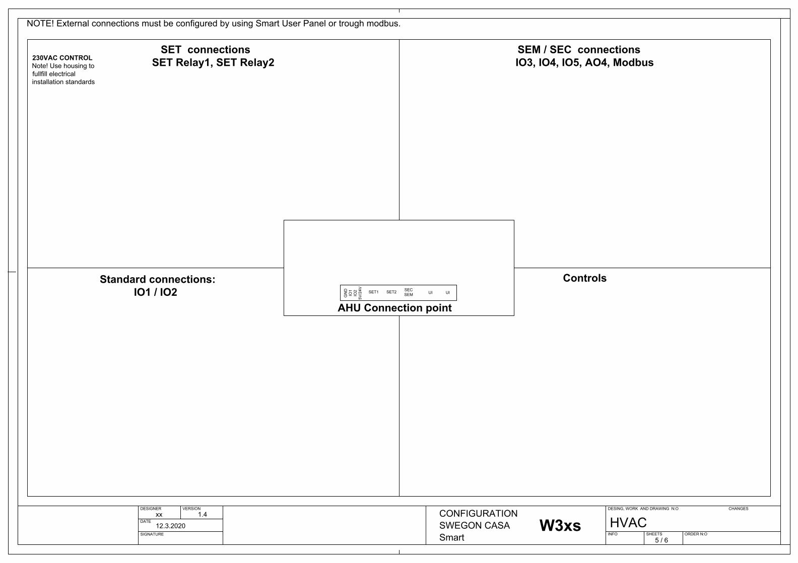
SET connections SET Relay1, SET Relay2
SEM / SEC connections IO3, IO4, IO5, AO4, Modbus
Standard connections: IO1 / IO2
Controls
AHU Connection point
230VAC Actuator
230VAC Supply
24V Actuator
POWER24V20W
POWER24V20W+
-SDCW
SDHW
SDHE Fresh
SDHE Supply
230VAC CONTROLNote! Use housing to fullfill electrical installation standards
24V CONTROL
X22
Smart AccessSMA
ETH
Smart AccessSMA
ETH
NOT AVAILABLEwhen Smart Access connected to SEC/SEM
connector
Smart User Panel
Smart Cooker Hood Smart Access
SMA
Modbus
Use Switch/ Button
DI1-5
24V24V
ModbusMaster
NOTE! External connections must be configured by using Smart User Panel or trough modbus.
W3W3 EconoW4W5W9W9 EconoR3
230VAC Actuator
230VAC Supply
24V Actuator
POWER24V20W
POWER24V20W+
-
230VAC CONTROLNote! Use housing to fullfill electrical installation standards
24V CONTROL
230VACActuator
230VAC Supply
24V Actuator
POWER24V20W
POWER24V20W+
-
SDHE Supply
230VAC CONTROLNote! Use housing to fullfill electrical installation standards
24V CONTROL
230VAC Actuator
230VAC Supply
24V Actuator
POWER24V20W
POWER24V20W+
-
SDHE Supply
230VAC CONTROLNote! Use housing to fullfill electrical installation standards
24V CONTROL
230VAC Actuator
230VAC Supply
24V Actuator
POWER24V20W
POWER24V20W+
-
230VAC CONTROLNote! Use housing to fullfill electrical installation standards
24V CONTROL
230VAC Actuator
230VAC Supply
24V Actuator
POWER24V20W
POWER24V20W+
-
24V CONTROL
230VAC Actuator
230VAC Supply
24V Actuator
POWER24V20W
POWER24V20W+
-
SDHE Supply
24V CONTROL
230VAC Actuator
230VAC Supply
24V Actuator
POWER24V20W
POWER24V20W+
-
SDHE Supply
24V CONTROL
R5-HR2R5R7/R7-HR9/R9-HR15/R15-H
POWER24V20W+
-
POWER24V20W+
-
POWER24V20W+
-
POWER24V20W+
-
POWER24V20W+
-
SDHWM
W4 Econo
SEM
SEM
SEM
Mod
bus
RTU
Terminated
A
B
o
o
A
B
o
o1
2
3
4 J
P 1
2
3
4
JP1
Smar
t uni
tSE
M
Bus
Term
inat
ed
NC
N
C
max
250
V/6A
SEM
Smar
t Ext
ensi
onM
odbu
s M
odul
e
MO
DB
US
OU
TM
OD
BU
S IN
Rel
ay 1
0-10VAO4
8
7
6
5
4
3
2
1
+5V
GN
D IO
5 IO
4 (IO
3) G
ND
AO
4 G
ND
0-10VAI3
GND
AO4
GND
IO3
IO4
IO5
GND
+5V
1 2 3 4 5 6 7 8
SECSmartExtensionCable
Modbus AModbus B
IO3IO4IO5
AO45V
GND
IO3 Relay
GND
AO4
IO3
GND
DI3
IO3
GNDNote! SEMRemove jumper JP2Note! SEMRemove jumper JP2
DO3
IO3
0-10VAI4
IO4
GND
DI4
IO4
GND
DO4
IO4
0-10VAI5
IO5
GND
DI5
IO5
GND
DO5
IO5
+24V
GND
GND
DO3 IO3 Relay
DI2
IO2
GND
DI1
IO1
GND
DO1
IO1
GND
DO2
IO2
GND
0-10VAI2
IO2
GND
0-10VAI1
IO1
GND
230VAC CONTROLNote! Use housing to fullfill electrical installation standards
DESIGNER VERSION
DATE
SIGNATURE
DESING, WORK AND DRAWING N:O
INFO SHEETS ORDER N:O
CHANGESxx 1.4
12.3.2020
CONFIGURATION SWEGON CASA Smart 5 / 6
HVAC1 2 3 4 5 6 7 8
ConnectionModule
SET T6SET T6SET T7SET T7SET T8
SET T9SET T9
SET T8Room Temp Sensor
W3xsW4xs
Supply Temp Sensor
Outside Temp Sensor
Supply Temp SensorWater Temp Sensor
Room Temp SensorSupply Temp SensorWater Temp Sensor
Rel
ay 1
Rel
ay 2
SET
Smar
t Ext
ensi
on T
empe
ratu
re m
odul
eSE
TSm
art E
xten
sion
Tem
pera
ture
mod
ule
1
2
3
4
5
6
7
8
9
10
11
12
AO1
A
O2
AO3
DI
max
50V
DC
NC
NC
NC
Smar
t uni
tSE
T2
SET
1
max
250
V/6A
max
250
V/6A Se
nsor
T6
T7
T8
T9
Rel
ay 1
Rel
ay 2
SET
Smar
t Ext
ensi
on T
empe
ratu
re m
odul
eSE
TSm
art E
xten
sion
Tem
pera
ture
mod
ule
1
2
3
4
5
6
7
8
9
10
11
12
AO1
A
O2
AO3
DI
max
50V
DC
NC
NC
NC
Smar
t uni
tSE
T2
SET
1
max
250
V/6A
max
250
V/6A Se
nsor
T6
T7
T8
T9
Rel
ay 1
Rel
ay 2
SET
Smar
t Ext
ensi
on T
empe
ratu
re m
odul
eSE
TSm
art E
xten
sion
Tem
pera
ture
mod
ule
1
2
3
4
5
6
7
8
9
10
11
12
AO1
A
O2
AO3
DI
max
50V
DC
NC
NC
NC
Smar
t uni
tSE
T2
SET
1
max
250
V/6A
max
250
V/6A Se
nsor
T6
T7
T8
T9
Rel
ay 1
Rel
ay 2
SET
Smar
t Ext
ensi
on T
empe
ratu
re m
odul
eSE
TSm
art E
xten
sion
Tem
pera
ture
mod
ule
1
2
3
4
5
6
7
8
9
10
11
12
AO1
A
O2
AO3
DI
max
50V
DC
NC
NC
NC
Smar
t uni
tSE
T2
SET
1
max
250
V/6A
max
250
V/6A Se
nsor
T6
T7
T8
T9
Rel
ay 1
Rel
ay 2
SET
Smar
t Ext
ensi
on T
empe
ratu
re m
odul
eSE
TSm
art E
xten
sion
Tem
pera
ture
mod
ule
1
2
3
4
5
6
7
8
9
10
11
12
AO1
A
O2
AO3
DI
max
50V
DC
NC
NC
NC
Smar
t uni
tSE
T2
SET
1
max
250
V/6A
max
250
V/6A Se
nsor
T6
T7
T8
T9
Rel
ay 1
Rel
ay 2
SET
Smar
t Ext
ensi
on T
empe
ratu
re m
odul
eSE
TSm
art E
xten
sion
Tem
pera
ture
mod
ule
1
2
3
4
5
6
7
8
9
10
11
12
AO1
A
O2
AO3
DI
max
50V
DC
NC
NC
NC
Smar
t uni
tSE
T2
SET
1
max
250
V/6A
max
250
V/6A Se
nsor
T6
T7
T8
T9
SET1 SET2 SECSEM UI UI
GN
DIO
1IO
25V
/24V
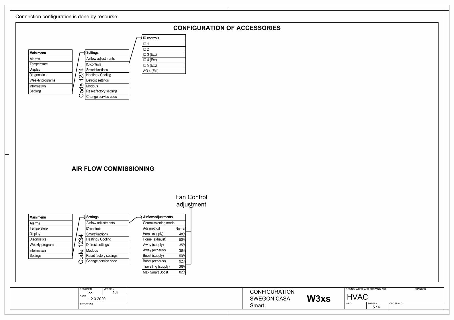
DESIGNER VERSION
DATE
SIGNATURE
DESING, WORK AND DRAWING N:O
INFO SHEETS ORDER N:O
CHANGESxx 1.4
12.3.2020
CONFIGURATION SWEGON CASA Smart 5 / 6
HVAC
CONFIGURATION OF ACCESSORIES
Connection configuration is done by resourse:
W3W3 EconoW4W5W9W9 EconoR3R5-HR2R5R7/R7-HR9/R9-HR15/R15-HW4 Econo
IO1ModbusSettings
AIR FLOW COMMISSIONING COOKER HOOD FUNCTION / BALANCING
Auto Home/Away/Boost function
AUTO AIR QUALITY CONTROL VOCAUTO HOME/AWAY/BOOST FUCNTION
SDHE FreshSDHWM
SDCWSDHWSDHE
Auto AirQuallity control
COOKER HOOD FUNCTION / BALANCINGCOOKER HOOD FUNCTION / BALANCING
AlarmsTemperatureDisplayDiagnosticsWeekly programsInformationSettings
Main menu
Airflow adjustments
Smart functionsHeating / CoolingDefrost settingsModbusReset factory settingsChange service code
Settings
IO controls
Control method
SetpointSetpoint (Away)Setpoint (travelling)Int. post heaterExt. post heater Post heater out limit
Heating / Cooling
Sensor / controls
Ext. post coolingExt. electric preheaterExt. liquid coil
8°C
16°C17°C17°C
v
IO 1IO 2IO 3 (Ext)IO 4 (Ext)IO 5 (Ext)AO 4 (Ext)
IO controls
IO2
Room air
Fine tuning RoomRoom air sensorFine tuning, supplySupply air sensorOutside air sensorWater radiator sens
Sensor / controls
Supply air
SET Relay 1SET Relay 2
0.0°CInternal
0.0°C
SET Relay1SET Relay2SET Relay1SET Relay2SET Relay1SET Relay2SET Relay1SET Relay2SET Relay1SET Relay2
SDHWSDCW
SDHWMSDHE Supply
Address
Data bitsStop bitsParitySmart Access
Modbus
Baud
None18
v
138 400
IO3IO4IO5AO4
IO3IO4IO5AO4
Commissioning mode
Home (supply)Home (exhaust)Away (supply)Away (exhaust)Boost (supply)Boost (exhaust)
Airflow adjustments
Adj. method
Travelling (supply)Max Smart Boost
48%50%35%38%90%92%
Normal
35%82%
Cod
e 12
34C
ode
1234
Fan Control adjustment
SET Relay1SET Relay2
IO1IO1IO2IO2
IO5IO4IO3
IO5IO4IO3IO3
Roof Fan
AlarmsTemperatureDisplayDiagnosticsWeekly programsInformationSettings
Main menu
Airflow adjustments
Smart functionsHeating / CoolingDefrost settingsModbusReset factory settingsChange service code
Settings
IO controls
SET T6-
SET T7
Control method
SetpointSetpoint (Away)Setpoint (travelling)Int. post heaterExt. post heater Post heater out limit
Heating / Cooling
Sensor / controls
Ext. post coolingExt. electric preheaterExt. liquid coil
8°C
16°C17°C17°C
v
Room air
Fine tuning RoomRoom air sensorFine tuning, supplySupply air sensorOutside air sensorWater radiator sens
Sensor / controls
Supply air
SET Relay 1SET Relay 2
0.0°CInternal
0.0°C
SET T6-
SET T7
AlarmsTemperatureDisplayDiagnosticsWeekly programsInformationSettings
Main menu
Cod
e 12
34
Airflow adjustments
Smart functionsHeating / CoolingDefrost settingsModbusReset factory settingsChange service code
Settings
IO controlsShortcuts
Cooker hood functionCentral vacuum functionFireplace functionAuto Home/Away/Boost funcAuto Humidity controlAuto Air Quality control
Smart functions
Summer night cooling
Balancing
Home state Compensat
Hood BoostRoof FanIn useCommissioning mode
Cooker hood function
Boost state Compensat.0%
v
20%0%
AlarmsTemperatureDisplayDiagnosticsWeekly programsInformationSettings
Main menu
Cod
e 12
34
Airflow adjustments
Smart functionsHeating / CoolingDefrost settingsModbusReset factory settingsChange service code
Settings
IO controlsShortcuts
Cooker hood functionCentral vacuum functionFireplace functionAuto Home/Away/Boost funcAuto Humidity controlAuto Air Quality control
Smart functions
Summer night coolingAlarmsTemperatureDisplayDiagnosticsWeekly programsInformationSettings
Main menu
Cod
e 12
34
Airflow adjustments
Smart functionsHeating / CoolingDefrost settingsModbusReset factory settingsChange service code
Settings
IO controlsShortcuts
Cooker hood functionCentral vacuum functionFireplace functionAuto Home/Away/Boost funcAuto Humidity controlAuto Air Quality control
Smart functions
Summer night cooling
Balancing
Home state Compensat
Hood BoostRoof FanIn useCommissioning mode
Cooker hood function
Boost state Compensat.0%
v
20%0%
AlarmsTemperatureDisplayDiagnosticsWeekly programsInformationSettings
Main menu
Cod
e 12
34
Airflow adjustments
Smart functionsHeating / CoolingDefrost settingsModbusReset factory settingsChange service code
Settings
IO controlsShortcuts
Cooker hood functionCentral vacuum functionFireplace functionAuto Home/Away/Boost funcAuto Humidity controlAuto Air Quality control
Smart functions
Summer night cooling
SDCW
Control method
SetpointSetpoint (Away)Setpoint (travelling)Int. post heaterExt. post heater Post heater out limit
Heating / Cooling
Sensor / controls
Ext. post coolingExt. electric preheaterExt. liquid coil
8°C
16°C17°C17°C
v
Room air
Fine tuning RoomRoom air sensorFine tuning, supplySupply air sensorOutside air sensorWater radiator sens
Sensor / controls
Supply air
SET Relay 1SET Relay 2
0.0°CInternal
0.0°C
SET T6-
SET T7
WSTC Room Temp PT1000 sensorWSTC Room Temp PT1000 sensor
Control method
SetpointSetpoint (Away)Setpoint (travelling)Int. post heaterExt. post heater Post heater out limit
Heating / Cooling
Sensor / controls
Ext. post coolingExt. electric preheaterExt. liquid coil
8°C
16°C17°C17°C
v
Room air
Fine tuning RoomRoom air sensorFine tuning, supplySupply air sensorOutside air sensorWater radiator sens
Sensor / controls
Supply air
SET Relay 1SET Relay 2
0.0°CInternal
0.0°C
SET T6-
SET T7
W3xsW4xs

EF1 SF1PH
F1+F2
EXHAUST SUPPLY
COMMON EXTRACT
SD1F3
CH EXHAUSTPRH
TX
SD2
SD1
M
SDHE SDCW
SDHE SDHWM
UPM
TX
SDHW
TX
TX
DESIGNER VERSION
DATE
SIGNATURE
DESING, WORK AND DRAWING N:O
INFO SHEETS ORDER N:O
CHANGESxx
1.4
12.3.2020
MODBUS REGISTERSSWEGON CASA Smart 6 / 6
HVAC
FLK
Room Temp
TXTX
EF1 SF1
F1 F2
IO3IO4IO5AO4
CH
IO3IO4IO5AO4
PH
AO4
S_P
E_PSD2
M
EF1 SF1
F1
T1
SD1 F2
HE
HE
Switch
CH
CH EXHAUST
Cooker Hood Exhaust
OUTSIDE
SD1
M
EF1 SF1PH
F1+F2SD1
F3PRH
HE
WARM WATER
M
WARM WATER
M
COLD LIQUID
M
M
EF1 SF1PH
F1+F2SD1
F3PRH
HE
WARM WATER
W3W3 EconoW4W5
EF1 SF1
F1 SD1 F2
W9
EF1 SF1PH
F1+F2SD1
F3PRH
HE
WARM WATER
W9 EconoR3
EF1 SF1
F1 F2
PH
HE
R5-H
EF1 SF1
F1 F2
PH
HE
R2
EF1 SF1
F1 F2
PH
HE
R5
EF1 SF1
F1 F2
PH
HE
R7/R7-H
EF1 SF1
F1 F2
HE
R9/R9-H
EF1 SF1
F1 F2
HE
R15/R15-H
Basic MODBUS definitions
T5 T2
T1 T3
T4
T SP
RH
CO2VOC
M M
M
TZA2TX02
M
TZA1TX01 T4
M
M
T SP
RH
TZA2TX02
T1
MT4
TZA1TX01 T4
M
M
T SP
RH
TZA2TX02
T1
T5M
T2T3
T4M
MT SP
RH
TZA2TX02
T5
T5M
T2T3
T4M
MT SP
RH
EF1 SF1PH
F1+F2SD1
F3PRH
HE
T5 T2
T1 T3
T4
T SP
RH
M M
M
EF1 SF1PH
F1+F2SD1
F3PRH
HE
WARM WATER
W4 Econo
TZA2TX02
T1
T5M
T2T3
T4M
MT SP
RH
T1
T4M M
T SP
RH
T1
M
TZA2TX02
MT4
T SP
RH
T1
M
TZA2TX02
MT4
T SP
RH
T1
M
TZA2TX02
MT4
T SP
RH
T1
M
TZA2TX02
MT4
T SP
RH
T1
M MT4
T SP
RH
T1
M MT4
T SP
RH
T3T3
T5T5T5T5
Outside Temp
Supply TempSupply Temp
Water Temp
IO1IO2IO1IO2IO1IO2IO1IO2IO1IO2IO1IO2IO1IO2IO1IO2IO1IO2IO1IO2IO1IO2IO1IO2IO1IO2IO1IO2IO1IO2
Exhaust temperature 3x6205
3x6304Exhaust fan control (%)
3x6306Exhaust fan RPM
3x6219Extract duct pressure(Pa)
3x6303Suply fan control (%)
3x6305Supply fan RPM
3x6218Supply duct pressure(Pa)
CONTROL -State: 0=Stopped, 1=Away, 2=Home, 3=Boost, 4=Travelling 4x5001
4x5018CONTROL -Emergency Stop:0=Normal, 1=Emergency Stop, 2= Emergency overpressure
3x6136Active Alarm:0= No alamr, non 0 = see bitwise definitions in register list.
3x6137Info Alarm:0= No alamr, non 0 = see bitwise definitions in register list.
4x5406Info Alarm:0= No alamr, non 0 = see bitwise definitions in register list.
Extract air temperature (0.1C) 3x6204
4x6214Relative humidity (%)
4x6215Absolute humidity (0.1g/m3)
4x6217Air Quality VOC (ppm)
4x6213Carbon Monokside CO2 (ppm)
Fresh air temperture T1 (0.1C) 3x6201
3x6344Preheater Control (%)
3x6345External Preheater(%)
3x6211Outside temperture T6-T9 (0.1C)Summer night cooling active 3x6334
3x6348HE Bypass(%)
Supply temperature setpoint (0.1C) 3x6203
4x5101CONTROL: Temperature setpoint
3x6317Post heating / cooling power (%)
3x6313Heating/cooling Boost (%)
3x6323Cooling Active
3x6301State0,1= Stopped, 2=Starting, 3=Normal, 4=Commissioning
3x6301Use State0 = Stopped, 2=Away, 3=Home, 4=Boost
3x6349-3x6353GIO1-5 DI Status (0/2)
3x6354-3x6358GIO1-5 AI value (mV)
4x5021-4x5025GIO1-5 DO Control (0/1)
4x5157-4x5161GIO1-5 Function
4x5026-4x5027SET1-2 DO Control (0/1)
4x5162-4x5162SET1-2 DO FunctionSupply temperature setpoint (0.1C) 3x6203
4x5101CONTROL: Temperature setpoint
3x6317Post heating / cooling power (%)
3x6313Heating/cooling Boost (%)
Extract air temperature (0.1C) 3x6204
4x6214Relative humidity (%)
4x6215Absolute humidity (0.1g/m3)
Fresh air temperture T1 (0.1C) 3x6201
3x6344Preheater Control (%)
3x6345External Preheater(%)
3x6211Outside temperture T6-T9 (0.1C)Summer night cooling active 3x6334
3x6348HE Bypass(%)
3x6303Suply fan control (%)
3x6305Supply fan RPM
Exhaust temperature 3x6205
3x6304Exhaust fan control (%)
3x6306Exhaust fan RPM
CONTROL -State: 0=Stopped, 1=Away, 2=Home, 3=Boost, 4=Travelling 4x5001
4x5018CONTROL -Emergency Stop:0=Normal, 1=Emergency Stop, 2= Emergency overpressure
3x6136Active Alarm:0= No alamr, non 0 = see bitwise definitions in register list.
3x6137Info Alarm:0= No alamr, non 0 = see bitwise definitions in register list.
4x5406Info Alarm:0= No alamr, non 0 = see bitwise definitions in register list.
3x6301State0,1= Stopped, 2=Starting, 3=Normal, 4=Commissioning
3x6301Use State0 = Stopped, 2=Away, 3=Home, 4=Boost
3x6349-3x6353GIO1-5 DI Status (0/2)
3x6354-3x6358GIO1-5 AI value (mV)
4x5021-4x5025GIO1-5 DO Control (0/1)
4x5157-4x5161GIO1-5 Function
4x5026-4x5027SET1-2 DO Control (0/1)
4x5162-4x5162SET1-2 DO FunctionSupply temperature setpoint (0.1C) 3x6203
4x5101CONTROL: Temperature setpoint
3x6317Post heating / cooling power (%)
3x6313Heating/cooling Boost (%)
Extract air temperature (0.1C) 3x6204
4x6214Relative humidity (%)
4x6215Absolute humidity (0.1g/m3)
Fresh air temperture T1 (0.1C) 3x6201
3x6344Preheater Control (%)
3x6345External Preheater(%)
3x6211Outside temperture T6-T9 (0.1C)Summer night cooling active 3x6334
3x6348HE Bypass(%)
3x6303Suply fan control (%)
3x6305Supply fan RPM3x6304Exhaust fan control (%)
3x6306Exhaust fan RPM
CONTROL -State: 0=Stopped, 1=Away, 2=Home, 3=Boost, 4=Travelling 4x5001
4x5018CONTROL -Emergency Stop:0=Normal, 1=Emergency Stop, 2= Emergency overpressure
3x6136Active Alarm:0= No alamr, non 0 = see bitwise definitions in register list.
3x6137Info Alarm:0= No alamr, non 0 = see bitwise definitions in register list.
4x5406Info Alarm:0= No alamr, non 0 = see bitwise definitions in register list.
3x6301State0,1= Stopped, 2=Starting, 3=Normal, 4=Commissioning
3x6301Use State0 = Stopped, 2=Away, 3=Home, 4=Boost
3x6349-3x6353GIO1-5 DI Status (0/2)
3x6354-3x6358GIO1-5 AI value (mV)
4x5021-4x5025GIO1-5 DO Control (0/1)
4x5157-4x5161GIO1-5 Function
4x5026-4x5027SET1-2 DO Control (0/1)
4x5162-4x5162SET1-2 DO FunctionSupply temperature setpoint (0.1C) 3x6203
4x5101CONTROL: Temperature setpoint
3x6317Post heating / cooling power (%)
3x6313Heating/cooling Boost (%)
Extract air temperature (0.1C) 3x6204
4x6214Relative humidity (%)
4x6215Absolute humidity (0.1g/m3)
Fresh air temperture T1 (0.1C) 3x6201
3x6344Preheater Control (%)
3x6345External Preheater(%)
3x6211Outside temperture T6-T9 (0.1C)
3x6303Suply fan control (%)
3x6305Supply fan RPM3x6304Exhaust fan control (%)
3x6306Exhaust fan RPM
CONTROL -State: 0=Stopped, 1=Away, 2=Home, 3=Boost, 4=Travelling 4x5001
4x5018CONTROL -Emergency Stop:0=Normal, 1=Emergency Stop, 2= Emergency overpressure
3x6136Active Alarm:0= No alamr, non 0 = see bitwise definitions in register list.
3x6137Info Alarm:0= No alamr, non 0 = see bitwise definitions in register list.
4x5406Info Alarm:0= No alamr, non 0 = see bitwise definitions in register list.
3x6301State0,1= Stopped, 2=Starting, 3=Normal, 4=Commissioning
3x6301Use State0 = Stopped, 2=Away, 3=Home, 4=Boost
3x6349-3x6353GIO1-5 DI Status (0/2)
3x6354-3x6358GIO1-5 AI value (mV)
4x5021-4x5025GIO1-5 DO Control (0/1)
4x5157-4x5161GIO1-5 Function
4x5026-4x5027SET1-2 DO Control (0/1)
4x5162-4x5162SET1-2 DO FunctionSupply temperature setpoint (0.1C) 3x6203
4x5101CONTROL: Temperature setpoint
3x6317Post heating / cooling power (%)
3x6313Heating/cooling Boost (%)
Extract air temperature (0.1C) 3x6204
4x6214Relative humidity (%)
4x6215Absolute humidity (0.1g/m3)
Fresh air temperture T1 (0.1C) 3x6201
3x6344Preheater Control (%)
3x6345External Preheater(%)
3x6211Outside temperture T6-T9 (0.1C)Summer night cooling active 3x6334
3x6348HE Bypass(%)
3x6303Suply fan control (%)
3x6305Supply fan RPM
Exhaust temperature 3x6205
3x6304Exhaust fan control (%)
3x6306Exhaust fan RPM
CONTROL -State: 0=Stopped, 1=Away, 2=Home, 3=Boost, 4=Travelling 4x5001
4x5018CONTROL -Emergency Stop:0=Normal, 1=Emergency Stop, 2= Emergency overpressure
3x6136Active Alarm:0= No alamr, non 0 = see bitwise definitions in register list.
3x6137Info Alarm:0= No alamr, non 0 = see bitwise definitions in register list.
4x5406Info Alarm:0= No alamr, non 0 = see bitwise definitions in register list.
3x6301State0,1= Stopped, 2=Starting, 3=Normal, 4=Commissioning
3x6301Use State0 = Stopped, 2=Away, 3=Home, 4=Boost
3x6349-3x6353GIO1-5 DI Status (0/2)
3x6354-3x6358GIO1-5 AI value (mV)
4x5021-4x5025GIO1-5 DO Control (0/1)
4x5157-4x5161GIO1-5 Function
4x5026-4x5027SET1-2 DO Control (0/1)
4x5162-4x5162SET1-2 DO FunctionSupply temperature setpoint (0.1C) 3x6203
4x5101CONTROL: Temperature setpoint
3x6317Post heating / cooling power (%)
3x6313Heating/cooling Boost (%)
Extract air temperature (0.1C) 3x6204
4x6214Relative humidity (%)
4x6215Absolute humidity (0.1g/m3)
Fresh air temperture T1 (0.1C) 3x6201
3x6344Preheater Control (%)
3x6345External Preheater(%)
3x6211Outside temperture T6-T9 (0.1C)Summer night cooling active 3x6334
3x6348HE Bypass(%)
3x6303Suply fan control (%)
3x6305Supply fan RPM
Exhaust temperature 3x6205
3x6304Exhaust fan control (%)
3x6306Exhaust fan RPM
CONTROL -State: 0=Stopped, 1=Away, 2=Home, 3=Boost, 4=Travelling 4x5001
4x5018CONTROL -Emergency Stop:0=Normal, 1=Emergency Stop, 2= Emergency overpressure
3x6136Active Alarm:0= No alamr, non 0 = see bitwise definitions in register list.
3x6137Info Alarm:0= No alamr, non 0 = see bitwise definitions in register list.
4x5406Info Alarm:0= No alamr, non 0 = see bitwise definitions in register list.
3x6301State0,1= Stopped, 2=Starting, 3=Normal, 4=Commissioning
3x6301Use State0 = Stopped, 2=Away, 3=Home, 4=Boost
3x6349-3x6353GIO1-5 DI Status (0/2)
3x6354-3x6358GIO1-5 AI value (mV)
4x5021-4x5025GIO1-5 DO Control (0/1)
4x5157-4x5161GIO1-5 Function
4x5026-4x5027SET1-2 DO Control (0/1)
4x5162-4x5162SET1-2 DO Function Water temperature (0.1C) 3x6209Water temperature (0.1C) 3x6209
T5T5
3x6332Rotor control (1/0)
Supply temperature setpoint (0.1C) 3x6203
4x5101CONTROL: Temperature setpoint
3x6317Post heating / cooling power (%)
3x6313Heating/cooling Boost (%)
Extract air temperature (0.1C) 3x6204
4x6214Relative humidity (%)
4x6215Absolute humidity (0.1g/m3)
Fresh air temperture T1 (0.1C) 3x6201
3x6344Preheater Control (%)
3x6345External Preheater(%)
3x6211Outside temperture T6-T9 (0.1C)
3x6303Suply fan control (%)
3x6305Supply fan RPM3x6304Exhaust fan control (%)
3x6306Exhaust fan RPM
CONTROL -State: 0=Stopped, 1=Away, 2=Home, 3=Boost, 4=Travelling 4x5001
4x5018CONTROL -Emergency Stop:0=Normal, 1=Emergency Stop, 2= Emergency overpressure
3x6136Active Alarm:0= No alamr, non 0 = see bitwise definitions in register list.
3x6137Info Alarm:0= No alamr, non 0 = see bitwise definitions in register list.
4x5406Info Alarm:0= No alamr, non 0 = see bitwise definitions in register list.
3x6301State0,1= Stopped, 2=Starting, 3=Normal, 4=Commissioning
3x6301Use State0 = Stopped, 2=Away, 3=Home, 4=Boost
3x6349-3x6353GIO1-5 DI Status (0/2)
3x6354-3x6358GIO1-5 AI value (mV)
4x5021-4x5025GIO1-5 DO Control (0/1)
4x5157-4x5161GIO1-5 Function
4x5026-4x5027SET1-2 DO Control (0/1)
4x5162-4x5162SET1-2 DO FunctionSupply temperature setpoint (0.1C) 3x6203
4x5101CONTROL: Temperature setpoint
3x6317Post heating / cooling power (%)
3x6313Heating/cooling Boost (%)
Extract air temperature (0.1C) 3x6204
4x6214Relative humidity (%)
4x6215Absolute humidity (0.1g/m3)
Fresh air temperture T1 (0.1C) 3x6201
3x6344Preheater Control (%)
3x6345External Preheater(%)
3x6211Outside temperture T6-T9 (0.1C)
3x6303Suply fan control (%)
3x6305Supply fan RPM
Exhaust temperature 3x6205
3x6304Exhaust fan control (%)
3x6306Exhaust fan RPM
CONTROL -State: 0=Stopped, 1=Away, 2=Home, 3=Boost, 4=Travelling 4x5001
4x5018CONTROL -Emergency Stop:0=Normal, 1=Emergency Stop, 2= Emergency overpressure
3x6136Active Alarm:0= No alamr, non 0 = see bitwise definitions in register list.
3x6137Info Alarm:0= No alamr, non 0 = see bitwise definitions in register list.
4x5406Info Alarm:0= No alamr, non 0 = see bitwise definitions in register list.
3x6301State0,1= Stopped, 2=Starting, 3=Normal, 4=Commissioning
3x6301Use State0 = Stopped, 2=Away, 3=Home, 4=Boost
3x6349-3x6353GIO1-5 DI Status (0/2)
3x6354-3x6358GIO1-5 AI value (mV)
4x5021-4x5025GIO1-5 DO Control (0/1)
4x5157-4x5161GIO1-5 Function
4x5026-4x5027SET1-2 DO Control (0/1)
4x5162-4x5162SET1-2 DO Function
3x6332Rotor control (1/0) 3x6332Rotor control (1/0) 3x6332Rotor control (1/0) 3x6332Rotor control (1/0) 3x6332Rotor control (1/0) 3x6332Rotor control (1/0)
3x6234Rotor RPM 3x6234Rotor RPM 3x6234Rotor RPM 3x6234Rotor RPM
Summer night cooling active 3x6334Summer night cooling active 3x6334Summer night cooling active 3x6334Summer night cooling active 3x6334Summer night cooling active 3x6334Summer night cooling active 3x6334Summer night cooling active 3x6334
TX
Room Temp
TX
Room Temp
EF1 SF1PH
F1SD1
F2PRH
HE
W3xs
T5 T2
T1
T4
T SP
RH
M M
M
IO1IO2
Exhaust temperature 3x6205
3x6304Exhaust fan control (%)
3x6306Exhaust fan RPM
3x6303Suply fan control (%)
3x6305Supply fan RPM
CONTROL -State: 0=Stopped, 1=Away, 2=Home, 3=Boost, 4=Travelling 4x5001
4x5018CONTROL -Emergency Stop:0=Normal, 1=Emergency Stop, 2= Emergency overpressure
3x6136Active Alarm:0= No alamr, non 0 = see bitwise definitions in register list.
3x6137Info Alarm:0= No alamr, non 0 = see bitwise definitions in register list.
4x5406Info Alarm:0= No alamr, non 0 = see bitwise definitions in register list.
Extract air temperature (0.1C) 3x6204
4x6214Relative humidity (%)
4x6215Absolute humidity (0.1g/m3)
Fresh air temperture T1 (0.1C) 3x6201
3x6344Preheater Control (%)
Summer night cooling active 3x6334
3x6348HE Bypass(%)
Supply temperature setpoint (0.1C) 3x6203
4x5101CONTROL: Temperature setpoint
3x6317Post heating / cooling power (%)
3x6313Heating/cooling Boost (%)
3x6301State0,1= Stopped, 2=Starting, 3=Normal, 4=Commissioning
3x6301Use State0 = Stopped, 2=Away, 3=Home, 4=Boost
3x6349-3x6353GIO1-5 DI Status (0/2)
3x6354-3x6358GIO1-5 AI value (mV)
4x5021-4x5025GIO1-5 DO Control (0/1)
4x5157-4x5161GIO1-5 Function
4x5026-4x5027SET1-2 DO Control (0/1)
4x5162-4x5162SET1-2 DO Function
EF1 SF1PH
F1SD1
F2PRH
HE
W4xs
T5 T2
T1
T4
T SP
RH
M M
M
IO1IO2
Exhaust temperature 3x6205
3x6304Exhaust fan control (%)
3x6306Exhaust fan RPM
3x6303Suply fan control (%)
3x6305Supply fan RPM
CONTROL -State: 0=Stopped, 1=Away, 2=Home, 3=Boost, 4=Travelling 4x5001
4x5018CONTROL -Emergency Stop:0=Normal, 1=Emergency Stop, 2= Emergency overpressure
3x6136Active Alarm:0= No alamr, non 0 = see bitwise definitions in register list.
3x6137Info Alarm:0= No alamr, non 0 = see bitwise definitions in register list.
4x5406Info Alarm:0= No alamr, non 0 = see bitwise definitions in register list.
Extract air temperature (0.1C) 3x6204
4x6214Relative humidity (%)
4x6215Absolute humidity (0.1g/m3)
Fresh air temperture T1 (0.1C) 3x6201
3x6344Preheater Control (%)
Summer night cooling active 3x6334
3x6348HE Bypass(%)
Supply temperature setpoint (0.1C) 3x6203
4x5101CONTROL: Temperature setpoint
3x6317Post heating / cooling power (%)
3x6313Heating/cooling Boost (%)
3x6301State0,1= Stopped, 2=Starting, 3=Normal, 4=Commissioning
3x6301Use State0 = Stopped, 2=Away, 3=Home, 4=Boost
3x6349-3x6353GIO1-5 DI Status (0/2)
3x6354-3x6358GIO1-5 AI value (mV)
4x5021-4x5025GIO1-5 DO Control (0/1)
4x5157-4x5161GIO1-5 Function
4x5026-4x5027SET1-2 DO Control (0/1)
4x5162-4x5162SET1-2 DO Function