Embed Size (px)
Citation preview
January 1999 - Draft doc.: IEEE 802.11-99/006IEEE P802.11Wireless LANs
Draft Proposal for a Wireless Personal Area Network Medium Access Control and Physical Layer Protocol
Date: January 8, 1999
Authors: Dr. Grant Carlson, Allen Heberling, James D. Allen
Eastman Kodak Company66 Eastman Avenue, Rochester, N.Y. 14650-2015
Phone: +1 716-588-1939Fax: +1 716-722-9053
e-mail: [email protected]
Abstract
The following proposal is provided in response to the Call For Proposals [ref: doc.: IEEE 802.11-98/199] requested by the IEEE 802.11 Wireless Personal Area Network Study Group. The intention of this proposal is to provide the Study Group with an overview of the approach that the RF Enabled Imaging Team is pursuing in developing an RF based communications system which will support these two data transfer rates:
1) a 20 Megabits/s (Mbps) mode for high speed data transfers in the 2.45 GHz ISM band.2) a 1 Mbps mode for WPAN devices requiring slower data rates in the 2.45 GHz ISM band.
This proposal provides information regarding the Physical Layer for an Multi-Media ISM band system.
Draft Submission page 1 Dr. G. Carlson, A. Heberling, J. Allen Eastman Kodak Co.
January 1999 - Draft doc.: IEEE 802.11-99/006
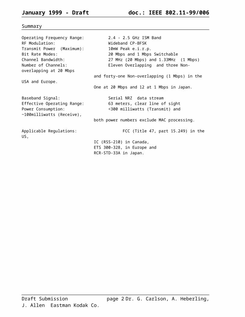
Summary
Operating Frequency Range: 2.4 - 2.5 GHz ISM BandRF Modulation: Wideband CP-BFSKTransmit Power (Maximum): 10mW Peak e.i.r.p.Bit Rate Modes: 20 Mbps and 1 Mbps SwitchableChannel Bandwidth: 27 MHz (20 Mbps) and 1.33MHz (1 Mbps)Number of Channels: Eleven Overlapping and three Non- overlapping at 20 Mbps
and forty-one Non-overlapping (1 Mbps) in the USA and Europe.One at 20 Mbps and 12 at 1 Mbps in Japan.
Baseband Signal: Serial NRZ data streamEffective Operating Range: 63 meters, clear line of sightPower Consumption: <300 milliwatts (Transmit) and ~100milliwatts (Receive),
both power numbers exclude MAC processing.
Applicable Regulations: FCC (Title 47, part 15.249) in the US, IC (RSS-210) in Canada,ETS 300-328, in Europe and RCR-STD-33A in Japan.
Draft Submission page 2 Dr. G. Carlson, A. Heberling, J. Allen Eastman Kodak Co.
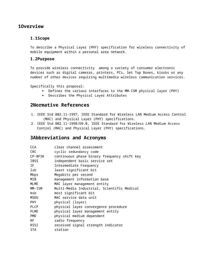
1Overview
1.1Scope
To describe a Physical Layer (PHY) specification for wireless connectivity of mobile equipment within a personal area network.
1.2Purpose
To provide wireless connectivity among a variety of consumer electronic devices such as digital cameras, printers, PCs, Set Top Boxes, kiosks or any number of other devices requiring multimedia wireless communication services.
Specifically this proposal:· Defines the various interfaces to the MM-ISM physical layer (PHY)· Describes the Physical Layer Attributes
2Normative References1. IEEE Std 802.11-1997, IEEE Standard for Wireless LAN Medium Access Control (MAC) and Physical
Layer (PHY) specifications.2. IEEE Std 802.11-1998/D9.0, IEEE Standard for Wireless LAN Medium Access Control (MAC) and Physical
Layer (PHY) specifications.
3Abbreviations and AcronymsCCA clear channel assessmentCRC cyclic redundancy codeCP-BFSK continuous phase binary frequency shift keyIBSS independent basic service setIF Intermediate Frequencylsb least significant bitMbps Megabits per secondMIB management information baseMLME MAC layer management entityMM-ISM Multi-Media Industrial, Scientific Medicalmsb most significant bitMSDU MAC service data unitPHY physical (layer)PLCP physical layer convergence procedurePLME physical layer management entityPMD physical medium dependentRF radio frequencyRSSI received signal strength indicatorSTA station
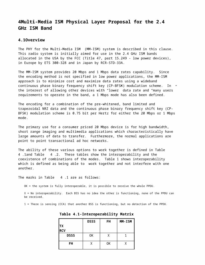
4Multi-Media ISM Physical Layer Proposal for the 2.4 GHz ISM Band
4.1Overview
The PHY for the Multi-Media ISM (MM-ISM) system is described in this clause. This radio system is initially aimed for use in the 2.4 GHz ISM bands allocated in the USA by the FCC (Title 47, part 15.249 - low power devices), in Europe by ETS 300-328 and in Japan by RCR-STD-33A.
The MM-ISM system provides 20 Mbps and 1 Mbps data rates capability. Since the encoding method is not specified in low power applications, the MM-ISM approach is to minimize cost and maximize data rates using a wideband continuous phase binary frequency shift key (CP-BFSK) modulation scheme. In the interest of allowing other devices with “lower” data rate and “many users” requirements to operate in the band, a 1 Mbps mode has also been defined.
The encoding for a combination of the pre-whitened, band limited and trapezoidal NRZ data and the continuous phase binary frequency shift key (CP-BFSK) modulation scheme is 0.75 bit per Hertz for either the 20 Mbps or 1 Mbps mode.
The primary use for a consumer priced 20 Mbps device is for high bandwidth, short range imaging and multimedia applications which characteristically have large amounts of data to transfer. Furthermore, the normal applications are point to point transactional ad hoc networks.
The ability of these various options to work together is defined in Table 4.1and Table 4.2. These tables show the interoperability and the coexistence of combinations of the modes. Table 1 shows interoperability which is defined as being able to work together and not interfere with one another.
The marks in Table 4.1 are as follows:
OK = the system is fully interoperable, it is possible to receive the whole PPDU.
X = No interoperability. Each BSS has no idea the other is functioning, none of the PPDU can be received.
1 = There is sensing (CCA) that another BSS is functioning, but no detection of the PPDU.
Table 4.1-Interoperability Matrix
TX DSSS FH MM-ISMRCV
DSSS OK X 1
FH X OK X
MM-ISM 1 X OK

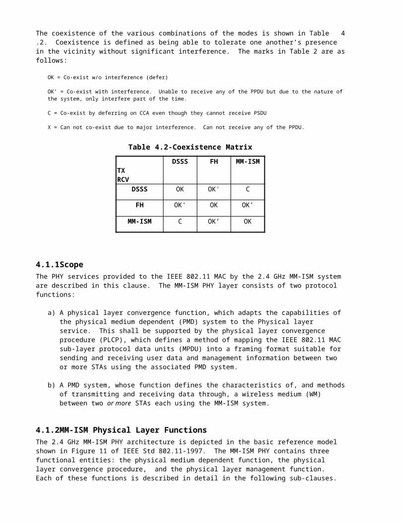
The coexistence of the various combinations of the modes is shown in Table 4.2. Coexistence is defined as being able to tolerate one another’s presence in the vicinity without significant interference. The marks in Table 2 are as follows:
OK = Co-exist w/o interference (defer)
OK’ = Co-exist with interference. Unable to receive any of the PPDU but due to the nature of the system, only interfere part of the time.
C = Co-exist by deferring on CCA even though they cannot receive PSDU
X = Can not co-exist due to major interference. Can not receive any of the PPDU.
Table 4.2-Coexistence Matrix
TX DSSS FH MM-ISMRCV
DSSS OK OK' C
FH OK' OK OK’
MM-ISM C OK’ OK
4.1.1ScopeThe PHY services provided to the IEEE 802.11 MAC by the 2.4 GHz MM-ISM system are described in this clause. The MM-ISM PHY layer consists of two protocol functions:
a) A physical layer convergence function, which adapts the capabilities of the physical medium dependent (PMD) system to the Physical layer service. This shall be supported by the physical layer convergence procedure (PLCP), which defines a method of mapping the IEEE 802.11 MAC sub-layer protocol data units (MPDU) into a framing format suitable for sending and receiving user data and management information between two or more STAs using the associated PMD system.
b) A PMD system, whose function defines the characteristics of, and methods of transmitting and receiving data through, a wireless medium (WM) between two or more STAs each using the MM-ISM system.
4.1.2MM-ISM Physical Layer FunctionsThe 2.4 GHz MM-ISM PHY architecture is depicted in the basic reference model shown in Figure 11 of IEEE Std 802.11-1997. The MM-ISM PHY contains three functional entities: the physical medium dependent function, the physical layer convergence procedure, and the physical layer management function. Each of these functions is described in detail in the following sub-clauses.
The MM-ISM Physical Layer service shall be provided to the Medium Access Control through the physical layer service primitives described in Clause 12 of IEEE Std 802.11-1997.
4.1.2.1Physical Layer Convergence Procedure (PLCP) SublayerTo allow a derivative IEEE 802.11 MAC to operate with minimum dependence on the physical medium dependent (PMD) sublayer, a physical layer convergence procedure (PLCP) sublayer is defined. This function simplifies the PHY service interface to the derivative IEEE 802.11 MAC services.
4.1.2.2Physical Medium Dependent (PMD) SublayerThe PMD sublayer provides a means of, and method of transmitting and receiving data through, a wireless medium (WM) between two or more STAs each using the MM-ISM system.
4.1.2.3Physical Layer Management Entity (PLME)The PLME performs management of the local PHY functions in conjunction with the MAC management entity.
4.2MM-ISM PLCP Sublayer
4.2.1OverviewThis clause provides a convergence procedure in which MPDUs are converted to and from PPDUs. During transmission, the MPDU shall be prepended with a PLCP preamble and header to create a PPDU. At the receiver, the PLCP preamble and header are processed to aid in demodulation and delivery of the MPDU.
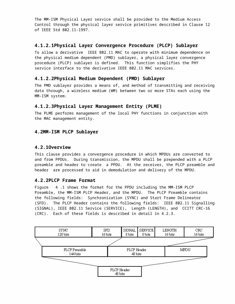
4.2.2PLCP Frame FormatFigure 4.1 shows the format for the PPDU including the MM-ISM PLCP Preamble, the MM-ISM PLCP Header, and the MPDU. The PLCP Preamble contains the following fields: Synchronization (SYNC) and Start Frame Delineator (SFD). The PLCP Header contains the following fields: IEEE 802.11 Signalling (SIGNAL), IEEE 802.11 Service (SERVICE), Length (LENGTH), and CCITT CRC-16 (CRC). Each of these fields is described in detail in 4.2.3.
Figure 4.1 - PLCP Frame Format
4.2.3PLCP Field DefinitionsThe entire PLCP Preamble and Header shall be transmitted using either the 1 Mbps or 20 Mbps CP-BFSK modulation described in 10.4.7. TBD is whether all transmitted bits shall be scrambled using the feedthrough scrambler described in 10.2.4.
4.2.3.1 PLCP Synchronization (SYNC)The SYNC field shall consist of 128 bits of scrambled “1” bits. This field shall be provided so that the receiver can perform the necessary operations for synchronization.
4.2.3.2PLCP Start Frame Delineator (SFD)The SFD shall be provided to indicate the start of the PHY dependent parameters within the PLCP preamble. The SFD shall be a 16 bit field, X’F3A0’ (msb to lsb). The lsb shall be transmitted first in time.
SFD: X’F3A0’ = 1111 0011 1010 0000 msb-lsb
4.2.3.3 PLCP 802.11 Signal Field (SIGNAL)The 8 bit 802.11 SIGNAL field indicates to the PHY the modulation that shall be used for transmission (and reception) of the PSDU. The data rate shall be equal to the SIGNAL field value multiplied by 100kbit/s. The MM-ISM PHY currently supports these two modulation services given by the following 8-bit words, where the lsb shall be transmitted first in time:
a) X’0A’ (msb to lsb) for 1 Mbps MM-ISMb) X’C8’ (msb to lsb) for 20 Mbps MM-ISM
4.2.3.4 PLCP 802.11 Service Field (SERVICE)The SERVICE field in the header shall be the same as the SERVICE field described in clause 15.2.3.4 of IEEE Std 802.11-1997.
4.2.3.5 PLCP Length Field (LENGTH)The Length field in the header shall be the same as the LENGTH field described in clause 15.2.3.5 of IEEE Std 802.11-1997.
4.2.3.6 PLCP CRC-16 Field (CRC)The CRC in the header shall be the same as the CRC field as defined in clause 15.2.3.6 of IEEE Std 802.11-1997. The CRC-16 is calculated over the SIGNAL, SERVICE, and LENGTH fields.
See Figures 87 and 88 in IEEE Std 802.11-1997.
4.2.4PLCP/MM-ISM PHY Data Scrambler and DescramblerTBD whether this is needed.
4.2.5PLCP Transmit ProcedureThe transmit procedure for a MM-ISM PHY is the same as those described in clause 15.2.6 of the IEEE Std 802.11-1997.
See Figures 91 and 92 in IEEE Std 802.11-1997.
4.2.6PLCP Receive ProcedureThe receive procedure for a MM-ISM PHY is the same as described in clause 15.2.7 of the IEEE Std 802.11-1997.
See Figures 93 and 94 in IEEE Std 802.11-1997.
4.3MM-ISM Physical Layer Management Entity (PLME)
4.3.1PLME_SAP Sublayer Management primitivesTable 3 lists the MIB attributes that may be accessed by the PHY sublayer entities and intralayer of higher layer management entities (LME). These attributes are accessed via the PLME-GET, PLME-SET, and PLME-RESET primitives defined in IEEE 802.11-1997 Clause 10.
4.3.2MM-ISM PHY Management Information Base (MIB)All MM-ISM PHY MIB attributes are defined in IEEE Std 802.11-1997 Annex D. Specific values are defined in Table 4.3.
Table 4.3-MIB Attribute Default Values/Ranges
Managed Object Default value/range Operational Semantics
xPhyOperationTablexPHYType MM-ISM-2.4(CP-BFSK) StaticxTempTypexCurrentRegDomain StaticxCurrentRegDomainsSupported StaticxPhyRateTablexSupportedDataRatesTx X’02’, X’28’ StaticxSupportedDataRatesRx X’02’, X’28’ StaticxPhyTxPowerTablexNumberSupportedPowerLevels 2 StaticxTxPowerLevel1 0 StaticxTxPowerLevel2 1 StaticxCurrentTxPowerLevel DynamicxPhyMM-ISMTablexCurrentChannel DynamicxCCAModeSupported StaticxCurrentCCAMode DynamicxEDThreshold Dynamic
4.3.3MM-ISM PHY characteristicsThe static MM-ISM PHY characteristic, provided through the PLME-CHARACTERISTICS service primitive, are shown in Table 4.4. The definitions of these characteristics are in IEEE 802.11-1999 clause 10.4.3.
Table 4.4-MM-ISM PHY Characteristics
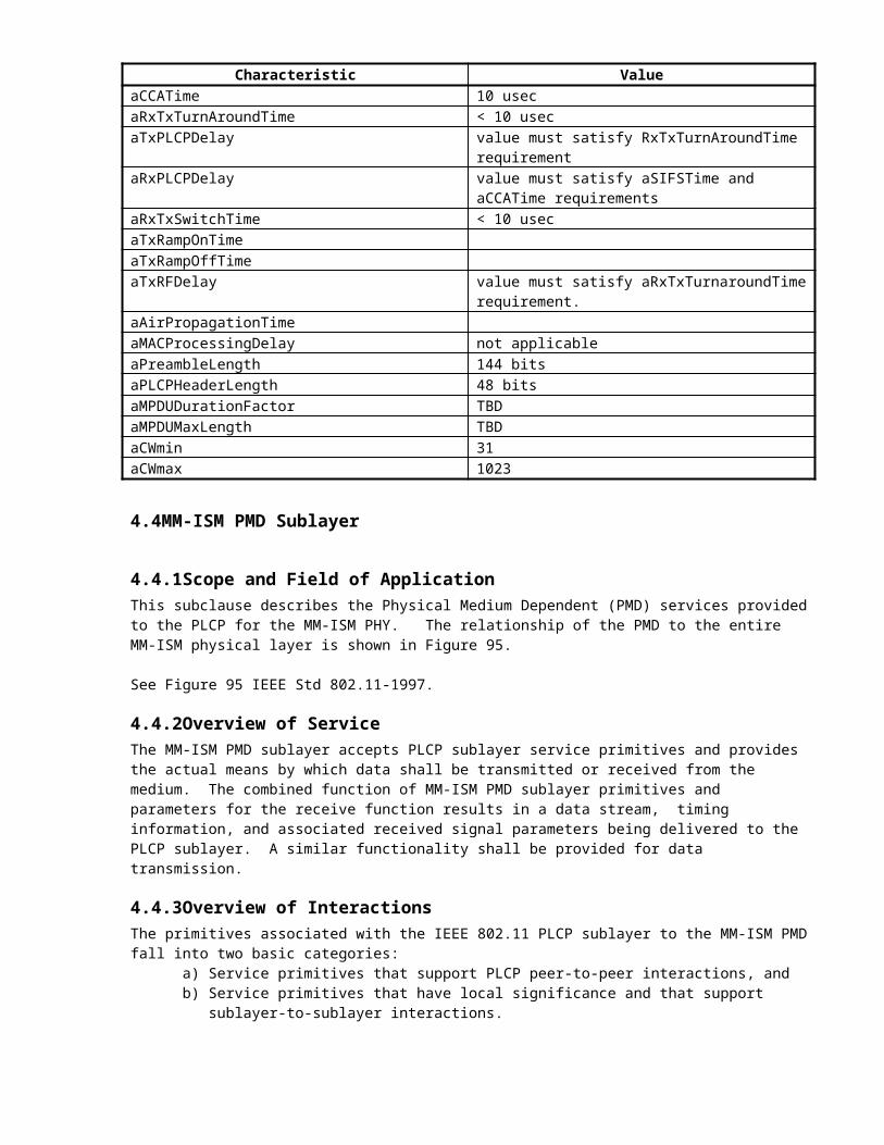
Characteristic ValueaSlotTime < 20 usecaSIFSTime 10 usecaCCATime 10 usecaRxTxTurnAroundTime < 10 usecaTxPLCPDelay value must satisfy RxTxTurnAroundTime requirementaRxPLCPDelay value must satisfy aSIFSTime and aCCATime
requirementsaRxTxSwitchTime < 10 usecaTxRampOnTimeaTxRampOffTimeaTxRFDelay value must satisfy aRxTxTurnaroundTime requirement.aAirPropagationTimeaMACProcessingDelay not applicableaPreambleLength 144 bitsaPLCPHeaderLength 48 bitsaMPDUDurationFactor TBD
Characteristic ValueaMPDUMaxLength TBDaCWmin 31aCWmax 1023
4.4MM-ISM PMD Sublayer
4.4.1Scope and Field of ApplicationThis subclause describes the Physical Medium Dependent (PMD) services provided to the PLCP for the MM-ISM PHY. The relationship of the PMD to the entire MM-ISM physical layer is shown in Figure 95.
See Figure 95 IEEE Std 802.11-1997.
4.4.2Overview of ServiceThe MM-ISM PMD sublayer accepts PLCP sublayer service primitives and provides the actual means by which data shall be transmitted or received from the medium. The combined function of MM-ISM PMD sublayer primitives and parameters for the receive function results in a data stream, timing information, and associated received signal parameters being delivered to the PLCP sublayer. A similar functionality shall be provided for data transmission.
4.4.3Overview of InteractionsThe primitives associated with the IEEE 802.11 PLCP sublayer to the MM-ISM PMD fall into two basic categories:
a) Service primitives that support PLCP peer-to-peer interactions, andb) Service primitives that have local significance and that support sublayer-to-sublayer interactions.
4.4.4Basic Service and OptionsAll of the service primitives described in this clause are considered mandatory unless otherwise specified.
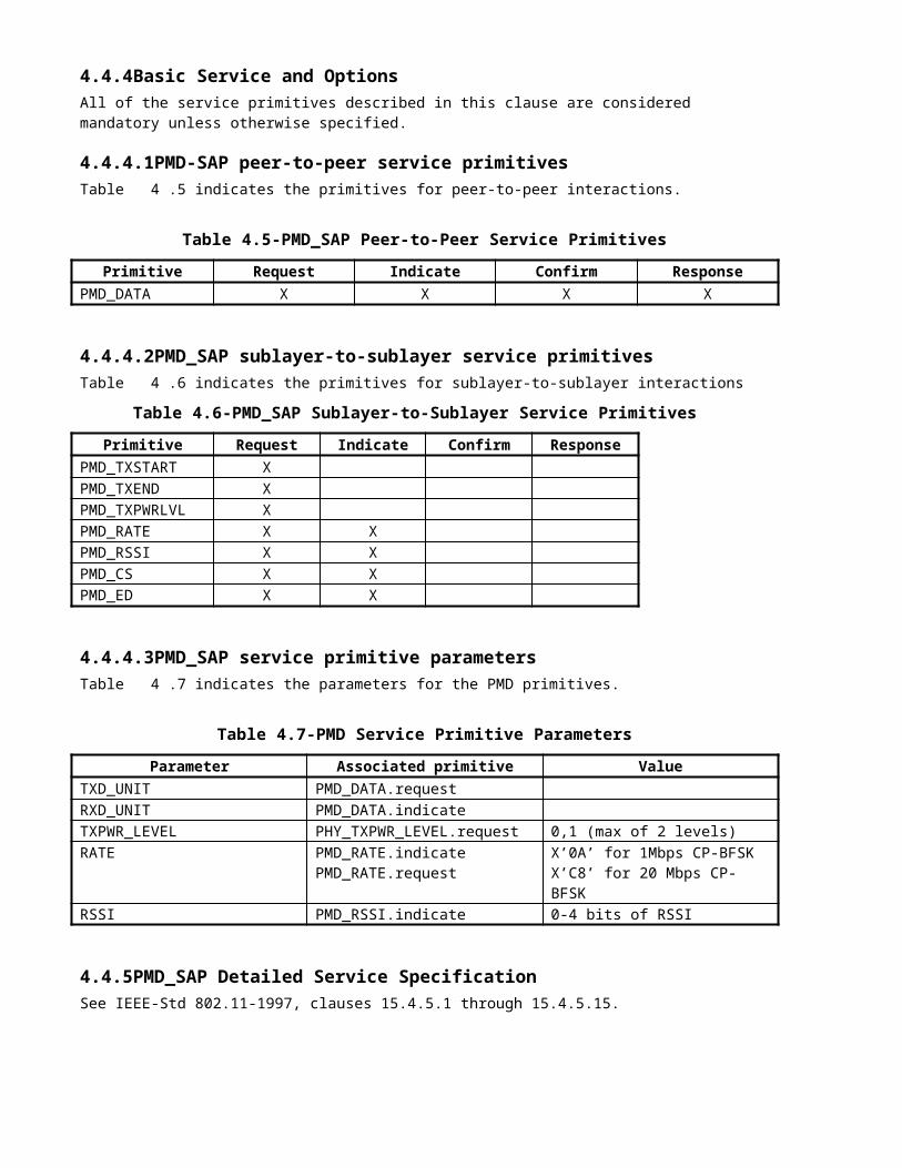
4.4.4.1PMD-SAP peer-to-peer service primitivesTable 4.5 indicates the primitives for peer-to-peer interactions.
Table 4.5-PMD_SAP Peer-to-Peer Service Primitives
Primitive Request Indicate Confirm ResponsePMD_DATA X X X X
4.4.4.2PMD_SAP sublayer-to-sublayer service primitivesTable 4.6 indicates the primitives for sublayer-to-sublayer interactions
Table 4.6-PMD_SAP Sublayer-to-Sublayer Service Primitives
Primitive Request Indicate Confirm ResponsePMD_TXSTART XPMD_TXEND XPMD_TXPWRLVL XPMD_RATE X XPMD_RSSI X XPMD_CS X XPMD_ED X X
4.4.4.3PMD_SAP service primitive parametersTable 4.7 indicates the parameters for the PMD primitives.
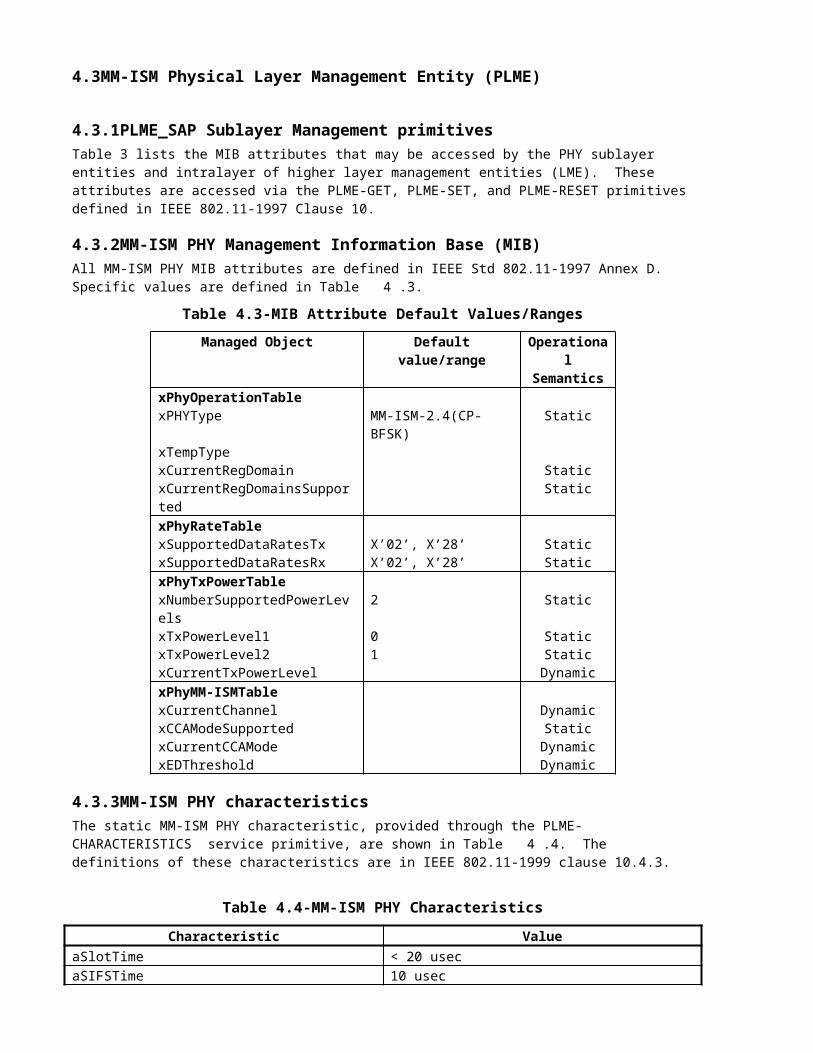
Table 4.7-PMD Service Primitive Parameters
Parameter Associated primitive ValueTXD_UNIT PMD_DATA.requestRXD_UNIT PMD_DATA.indicateTXPWR_LEVEL PHY_TXPWR_LEVEL.request 0,1 (max of 2 levels)RATE PMD_RATE.indicate
PMD_RATE.requestX’0A’ for 1Mbps CP-BFSKX’C8’ for 20 Mbps CP-BFSK
RSSI PMD_RSSI.indicate 0-4 bits of RSSI
4.4.5PMD_SAP Detailed Service SpecificationSee IEEE-Std 802.11-1997, clauses 15.4.5.1 through 15.4.5.15.
4.4.6PMD Operating Specifications GeneralThe following clauses provide general specifications for the MM-ISM Physical Medium Dependent sublayer. These specifications apply to both the receive and the transmit functions and general operation of a MM-ISM PHY.
4.4.6.1Operating Frequency RangeThe 2.4GHz to 2.5GHz ISM band will initially be the frequency range of operation. Japanese regulatory authorities limit operation to a narrower portion of the band between 2.471GHz and 2.497GHz . Regulatory bodies in the US, Canada and Europe limit operation from 2.4GHz to 2.4835GHz. Operation at 5 GHz may be applicable in the future for yet higher speed applications.
4.4.6.2Number of Operating Channels
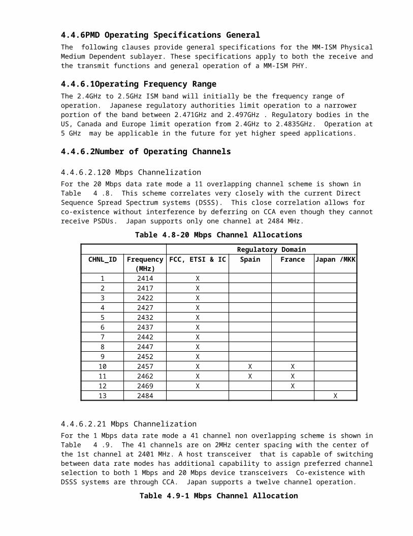
4.4.6.2.120 Mbps ChannelizationFor the 20 Mbps data rate mode a 11 overlapping channel scheme is shown in Table 4.8. This scheme correlates very closely with the current Direct Sequence Spread Spectrum systems (DSSS). This close correlation allows for co-existence without interference by deferring on CCA even though they cannot receive PSDUs. Japan supports only one channel at 2484 MHz.
Table 4.8-20 Mbps Channel Allocations
Regulatory DomainCHNL_ID Frequency FCC, ETSI & IC Spain France Japan
/MKK(MHz)
1 2414 X2 2417 X3 2422 X4 2427 X5 2432 X6 2437 X7 2442 X8 2447 X9 2452 X10 2457 X X X11 2462 X X X12 2469 X X13 2484 X
4.4.6.2.21 Mbps Channelization
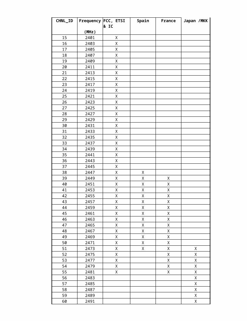
For the 1 Mbps data rate mode a 41 channel non overlapping scheme is shown in Table 4.9. The 41 channels are on 2MHz center spacing with the center of the 1st channel at 2401 MHz. A host transceiver that is capable of switching between data rate modes has additional capability to assign preferred channel selection to both 1 Mbps and 20 Mbps device transceivers Co-existence with DSSS systems are through CCA. Japan supports a twelve channel operation.
Table 4.9-1 Mbps Channel Allocation
Regulatory DomainsCHNL_ID Frequency FCC, ETSI
& ICSpain France Japan /MKK
(MHz)15 2401 X16 2403 X17 2405 X18 2407 X19 2409 X20 2411 X21 2413 X22 2415 X23 2417 X24 2419 X25 2421 X26 2423 X27 2425 X28 2427 X29 2429 X30 2431 X31 2433 X32 2435 X33 2437 X34 2439 X35 2441 X36 2443 X37 2445 X38 2447 X X39 2449 X X X40 2451 X X X41 2453 X X X42 2455 X X X43 2457 X X X44 2459 X X X45 2461 X X X46 2463 X X X47 2465 X X X48 2467 X X X49 2469 X X X50 2471 X X X51 2473 X X X X52 2475 X X X53 2477 X X X54 2479 X X X55 2481 X X X56 2483 X57 2485 X58 2487 X59 2489 X60 2491 X
61 2493 X62 2495 X
4.4.6.3Modulation DescriptionThe RF modulation technique employed in this system is a special form of Frequency Modulation (FM). Digital binary data is presented to the transmitter in a serial NRZ stream. The NRZ stream directly modulates a VCO in a PLL within an IF to create a continuous phase binary frequency shift key (CP-BFSK) signal. The NRZ data stream is pre-whitened, bandlimited and trapezoidal shaped before modulating the VCO. The modulation index is variable with an average modulation index for the bandlimited random data of approximately 1.75. A minimum of 4 sidebands are present at all times in the modulation spectrum. This wideband approach yields a receiver output signal to noise ratio 6 to 7 dB better then DSBSC.
4.4.6.4Channel Data RatesThe system has two selectable data rates: a high speed rate at 20 Mbps and a lower speed rate at 1 Mbps. Transceivers can switch between the two data rates depending upon the intended application. Both data rates use the same modulation technique. The deviation ratio remains constant for both data rates.
4.4.6.5Transmit and Receive Spurious EmissionsThe MM-ISM PHY shall conform with out-of-band spurious emissions as set by regulatory bodies. For the USA, refer to FCC 15.249, 15.205, and 15.209. For Europe , refer to ETS 300-328.
4.4.6.6Transmit to Receive Turn Around TimeTransmit to receive turn around time including T/R and LO switch times is less than 10 usec.
4.4.6.7Receive to Transmit Turn Around TimeReceive to transmit turn around time including, PA ramp up and T/R and LO switch times is less than 10 usec.
4.4.6.8Slot TimeThe slot time for the MM-ISM PHY shall be the sum of the RX-to-TX turnaround time ( <= 10 usec) and the energy detect time ( 10 usec as specified in clause 4.4.8.4 of this document). The propagation delay shall be regarded as being included in the energy detect time.
4.4.6.9Transmit and Receiver Antenna Port ImpedanceThe impedance of the transmit and receive antenna port is 50 ohms unbalanced.
4.4.6.10Operating Temperature RangeNominal operating temperature of the transceiver is 25 degrees C. The operating temperature range is from 0 to 70 degrees C. Minor degradation in performance occur at the temperature extremes.
4.4.7PMD Transmit SpecificationsThe following clauses describe the transmit functions and parameters associated with the Physical Medium Dependent sublayer.
4.4.7.1Transmit Power LevelsThe system transmitter has two power levels. The maximum transmitted peak power is 10mW (10dBm) or-20dBW equivalent isotropically radiated power (e.i.r.p.) . This limit applies for any combination of power level and antenna assembly. The peak power density is limited to -20dBW per 1 MHz. Transmitter has a lower power level at 15dB below the maximum peak power of 10 dBm.
4.4.7.2Transmit Spectrum Masks
4.4.7.2.120 Mbps Transmit Spectrum MaskTransmission mask for 20 Mbps data rate mode is shown in Figure 4.2. The wideband CP-BFSK envelope used in MM-ISM system has much lower sidelobes than a BPSK system. Main lobe width is approximately 27 MHz wide at 40 dB down.
Figure 4.2 - 20 Mbps Transmit Spectrum Mask

4.4.7.2.21 Mbps Transmit Spectrum MaskTransmission mask for the 1Mbps data rate mode is shown in Figure 4.3. Main lobe is 1.33 MHz wide at 40 dB down.
Figure 4.3 - 1 Mbps Transmit Spectrum Mask
4.4.7.3Transmit Center Frequency ToleranceCarrier frequency is crystal controlled with frequency tolerance of 50ppm and an aging of 5ppm per year.
4.4.7.4Symbol Clock Frequency ToleranceSymbol clock is used for creation of the NRZ data stream. Clock is crystal controlled with a frequency tolerance of 50 ppm and an aging of 5 ppm per year.
4.4.7.5Transceiver Initial Power-onTransceiver initial power on from sleep mode is less than 10 msec including 1 msec for PLLaddress and subsequent carrier frequency lock.
4.4.7.6RF Carrier SuppressionCarrier suppression is not performed as the system modulation is FM. The transmission spectrum mask reveals carrier power 5dB less then the peak power of the spectrum. This correlates with Bessel functions for average modulation index of 1.75.
4.4.8PMD Receiver SpecificationsThe following clauses describe the receive functions and parameters associated with the Physical Medium Dependent sublayer.
4.4.8.1Receiver Minimum Input Level SensitivityThe receiver provides a bit error rate (BER) of less than 10E-06 with -80dBm measured at the antenna connector.
4.4.8.2Receiver Maximum Input LevelThe receiver provides a bit error rate (BER) of less than 10E-06 with -10dBm measured at the antenna connector.
4.4.8.3Receiver Adjacent Channel RejectionFor the 20 Mbps data rate mode, the adjacent channel rejection between any two channels with 27MHz spacing is greater than 40 dB as shown in Figure 4.4. For the 1 Mbps mode adjacent channel noise with 2 MHz spacing is greater than 40 dB as shown in Figure 4.5.
Figure 4.4

Figure 4.5
4.4.8.4Clear Channel Assessment (CCA)Clear channel Assessment (CCA) is derived from the analog Received Signal Strength Indicator (RSSI) current created in the IF amplifier strip in the receiver. For this system a 4 bit Analog to Digital converter is used to convert the analog RSSI signal to a digital 4 bit CCA. The CCA is updated and latched every 10 usec while the receiver is operating. The CCA is used for carrier sense and to detect energy in the band above or below a specified threshold. The CCA is also used to determine if received signal to noise ratio is sufficient for proper reception. Each bit of the CCA represents a 5dB increase in energy in the band. When operating the transceiver in the 20 Mbps data rate mode, there is no detectable difference between receiving the 20 Mbps modulated signal or an unmodulated carrier such that they have the same transmitted peak power. The CCA is compatible for performing carrier sense and threshold detection with current DSSS systems.

![11 Literatur - link.springer.com3A978-3... · Wireless LAN Medium Access Contra! (MAC) and Physical Layer (PHY) Specifications. ANSI!IEEE Std 802.11, 1999 Edition. [S02.11i] IEEE](https://img.pdfslide.net/doc/110x75/5ede4205ad6a402d66699451/11-literatur-link-3a978-3-wireless-lan-medium-access-contra-mac-and-physical.jpg)