Embed Size (px)
Citation preview
November, 201417 doc.: IEEE 802.11-yy/xxxxr0
IEEE P802.11Wireless LANs
IMT-2020 (S)RIT Description Template – Characteristic Template
Date: 2017-11-17
Author(s):Name Affiliation Address Phone email
Author 1 Affiliation 1 Address 1 Phone 1 Email 1
RIT Description – Characteristic Template page 1 Author Names here
AbstractThis document is the RIT/SRIT description template, prepared in accordance with the submission guidelines for IMT-2020 submissions as described in the ITU-R/WP-5D Document M.[IMT-2020.SUBMISSION] titled “Requirements, evaluation criteria and submission templates for the development of IMT-2020”.
The description template is a template for the description of the characteristics of a candidate RIT or SRIT. It shall be used by the proponents to describe their proposal for a radio interface for IMT 2020 to a level of detail that will facilitate a sufficient understanding of the proposed technology in order to enable an independent technical assessment of compliance with the IMT 2020 requirements as specified in the “Requirements, evaluation criteria and submission templates for the development of IMT-2020” document.
The inclusion of an item in this template shall not imply that it is a minimum requirement of IMT 2020. It contains information beyond what the template requires to assist in the assessment of this (S)RIT.
Items that are not relevant for this proposal have been answered N/A (Not Applicable); often with an explanation of why the item is not applicable.
1
2
3
4
1
November, 201417 doc.: IEEE 802.11-yy/xxxxr0
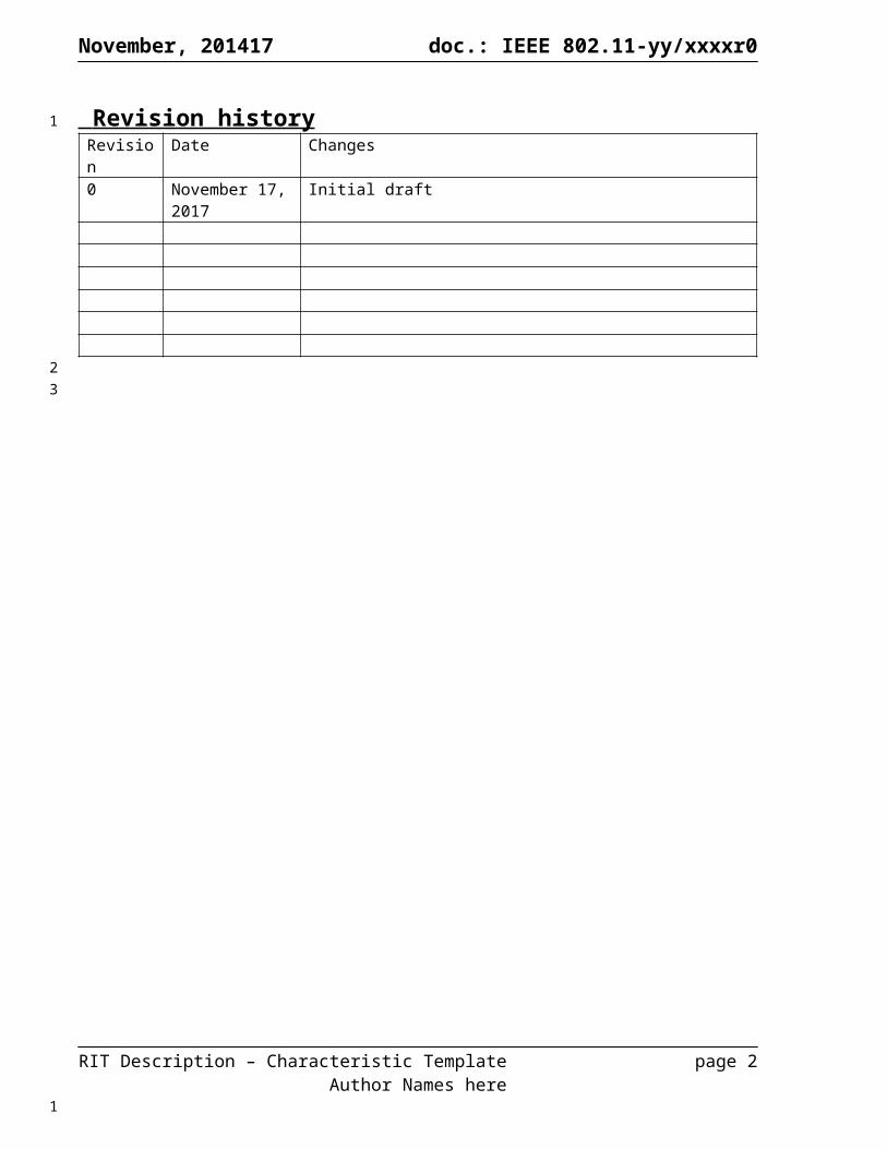
Revision history Revision Date Changes0 November 17,
2017Initial draft
RIT Description – Characteristic Template page 2 Author Names here
1
23
1
November, 201417 doc.: IEEE 802.11-yy/xxxxr0
ContentsRevision history.............................................................................................................................................25.2.3.2.1 Test Environment(s)............................................................................................................4
5.2.3.2.1.1 Test Environments.......................................................................................................4
5.2.3.2.2 Radio Interface Functional Aspects...............................................................................5
5.2.3.2.2.1 Multiple Access Schemes..........................................................................................5
5.2.3.2.2.2 Modulation Scheme.....................................................................................................5
5.2.3.2.2.2.1 Modulation Scheme.............................................................................................5
5.2.3.2.2.2.2 PAPR..........................................................................................................................5
5.2.3.2.2.3 Error Control Coding Scheme and Interleaving................................................5
5.2.3.2.2.3.1 Details of Error Control Coding Scheme......................................................5
5.2.3.2.2.3.2 Bit Interleaving Scheme.....................................................................................5
5.2.3.2.3 Channel Tracking Capabilities.........................................................................................6
5.2.3.2.4 Physical Channel Structure and Multiplexing............................................................7
5.2.3.2.4.1 Physical Channel Bit Rate.........................................................................................7
5.2.3.2.4.2 Layer 1 and Layer 2 Overhead Estimation.........................................................7
5.2.3.2.4.3 Variable Bit Rate Capabilities..................................................................................7
5.2.3.2.4.4 Variable Payload Capabilities..................................................................................7
5.2.3.2.4.5 Signaling Transmission Scheme.............................................................................7
5.2.3.2.4.6 Small Signaling Overhead.........................................................................................7
5.2.3.2.5 Mobility Management (Handover).................................................................................8
5.2.3.2.5.1 Handover Mechanisms...............................................................................................8
5.2.3.2.5.2 Simultaneous Handover Requirements...............................................................8
5.2.3.2.6 Radio Resource Management..........................................................................................9
5.2.3.2.6.1 Radio Resource Management..................................................................................9
5.2.3.2.6.2 Inter-RIT Interworking.................................................................................................9
5.2.3.2.6.3 Connection/Session Management..........................................................................9
5.2.3.2.7 Frame Structure..................................................................................................................10
5.2.3.2.7.1 Frame Structure for Downlink and Uplink.........................................................10
5.2.3.2.8 Spectrum Capabilities and Duplex Technologies...................................................11
5.2.3.2.8.1 Spectrum Sharing and Flexible Spectrum Use................................................11
5.2.3.2.8.2 Channel Bandwidth Scalability..............................................................................11
5.2.3.2.8.3 Frequency Bands Supported by the RIT/SRIT..................................................11
5.2.3.2.8.4 Minimum Amount of Spectrum Required..........................................................11
5.2.3.2.8.5 Minimum and Maximum Transmission Bandwidth (Mhz) Measured at The 3 Db Down Points.....................................................................................................................11
5.2.3.2.8.6 Duplexing Scheme(S)...............................................................................................11
5.2.3.2.9 Support of Advanced Antenna Capabilities..............................................................13
RIT Description – Characteristic Template page 3 Author Names here
12
3
4
5
6
7
8
9
10
11
12
13
14
15
16
17
18
19
20
21
22
23
24
25
26
27
28
29
30
31
32
33
34
3536
37
38
1
November, 201417 doc.: IEEE 802.11-yy/xxxxr0
5.2.3.2.9.1 Multi-Antenna Systems............................................................................................13
5.2.3.2.9.2 Supported Antenna Elements................................................................................13
5.2.3.2.9.3 Antenna Configuration.............................................................................................13
5.2.3.2.9.4 Spatial Multiplexing (MIMO)...................................................................................13
5.2.3.2.9.5 Other Antenna Technologies.................................................................................13
5.2.3.2.9.6 Antenna Tilt Angle......................................................................................................13
5.2.3.2.10 Link Adaptation and Power Control..........................................................................14
5.2.3.2.10.1 Adaptation Techniques Employed by RIT/SRIT.............................................14
5.2.3.2.10.2 Power Control Scheme...........................................................................................14
5.2.3.2.11 Power Classes...................................................................................................................15
5.2.3.2.11.1 UE Emitted Power....................................................................................................15
5.2.3.2.11.1.1 Radiated Antenna Power...............................................................................15
5.2.3.2.11.1.2 Maximum Peak Transmitted Power...........................................................15
5.2.3.2.11.1.3 Time Averaged Transmitted Power...........................................................15
5.2.3.2.11.2 Base Station Emitted Power................................................................................15
5.2.3.2.11.2.1 Base Station Transmit Power......................................................................15
5.2.3.2.11.2.2 Maximum Peak Transmitted Power...........................................................15
5.2.3.2.11.2.3..............................................................................Average Transmitted Power15
5.2.3.2.12 Scheduler, Qos Support and Management, Data Services..............................16
5.2.3.2.12.1 Qos Support...............................................................................................................16
5.2.3.2.12.2 Scheduling Mechanisms........................................................................................16
5.2.3.2.13 Radio Interface Architecture and Protocol Stack.................................................17
5.2.3.2.13.1 Radio Interface Architecture and Protocol Stack.........................................17
5.2.3.2.13.2 Bit Rate Required for Transmitting Feedback Information......................17
5.2.3.2.13.3 Channel Access.........................................................................................................17
5.2.3.2.14 Cell Selection.....................................................................................................................18
5.2.3.2.14.1 RIT/SRIT Accomplishes Cell Selection..............................................................18
5.2.3.2.15 Location Determination Mechanisms.......................................................................19
5.2.3.2.15.1 Location Determination Mechanisms...............................................................19
5.2.3.2.16 Priority Access Mechanisms........................................................................................20
5.2.3.2.16.1 Techniques Employed to Support......................................................................20
5.2.3.2.17 Unicast, Multicast and Broadcast..............................................................................21
5.2.3.2.17.1 Enabling RIT/SRIT.....................................................................................................21
5.2.3.2.17.2 Capable of Providing Multiple User Services.................................................21
5.2.3.2.17.3 Codec............................................................................................................................21
5.2.3.2.18 Privacy, Authorization, Encryption, Authentication and Legal Intercept Schemes...................................................................................................................................................22
RIT Description – Characteristic Template page 4 Author Names here
1
2
3
4
5
6
7
8
9
10
11
12
13
14
15
16
17
1819
20
21
22
23
24
25
26
27
28
29
30
31
32
33
34
35
36
3738
1
November, 201417 doc.: IEEE 802.11-yy/xxxxr0
5.2.3.2.18.1 Privacy, Authorization, Encryption, Authentication and Legal Intercept Schemes...............................................................................................................................................22
5.2.3.2.19 Frequency Planning........................................................................................................23
5.2.3.2.19.1 Adding New Cells or New RF Carriers..............................................................23
5.2.3.2.20 Interference Mitigation Within Radio Interface....................................................24
5.2.3.2.20.1 Interference Mitigation..........................................................................................24
5.2.3.2.20.2 Signaling for Intercell Interference Mitigation..............................................24
5.2.3.2.20.3 Link Level Interference Mitigation.....................................................................24
5.2.3.2.20.4 Cope with Multipath Propagation Effects........................................................24
5.2.3.2.20.5 Diversity Techniques..............................................................................................24
5.2.3.2.21 Synchronization Requirements..................................................................................25
5.2.3.2.21.1 RIT’s/SRIT’s Timing Requirements....................................................................25
5.2.3.2.21.2 Synchronization Mechanisms..............................................................................25
5.2.3.2.22 Link Budget Template....................................................................................................26
5.2.3.2.23 Support for Wide Range Of Services........................................................................27
5.2.3.2.23.1 Services/Applications.............................................................................................27
5.2.3.2.23.2 Range of Services Across Different Usage Scenarios................................27
5.2.3.2.24 Global Circulation of Terminals..................................................................................28
5.2.3.2.25 Energy Efficiency.............................................................................................................29
5.2.3.2.26 Other Items........................................................................................................................30
5.2.3.2.26.1 Coverage Extension Schemes.............................................................................30
5.2.3.2.26.2 Self-Organization.....................................................................................................30
5.2.3.2.26.3 Frequency Reuse Schemes..................................................................................30
5.2.3.2.26.4 RIT/Component RIT Evolution.............................................................................30
5.2.3.2.26.5 Specific Spectrum Mask........................................................................................30
5.2.3.2.26.6 UE Power Saving Mechanisms............................................................................30
5.2.3.2.26.7 Simulation Process Issues....................................................................................30
5.2.3.2.26.8 Operational Life Time.............................................................................................30
5.2.3.2.26.9 Latency for Infrequent Small Packet................................................................30
5.2.3.2.26.10 Control Plane Latency..........................................................................................30
5.2.3.2.26.11 Reliability..................................................................................................................30
5.2.3.2.26.12 Mobility......................................................................................................................30
5.2.3.2.27 Other Information............................................................................................................32
5.2.3.3 Link Budgets............................................................................................................................33
5.2.3.3.1 Link Budget Template for Indoor Hotspot-eMBB................................................33
5.2.3.3.2 Link Budget Template for Dense Urban-eMBB2..................................................36
5.2.3.3.3 Link Budget Template for Rural-eMBB......................................................................39
5.2.3.3.4 Link Budget Template for Urban Macro–mMTC.....................................................42
RIT Description – Characteristic Template page 5 Author Names here
12
3
4
5
6
7
8
9
10
11
12
13
14
15
16
17
18
19
20
21
22
23
24
25
26
27
28
29
30
31
32
33
34
35
36
37
38
1
November, 201417 doc.: IEEE 802.11-yy/xxxxr0
5.2.3.3.5 Link Budget Template for Urban Macro–URLLC.....................................................45
RIT Description – Characteristic Template page 6 Author Names here
1
23
1
November, 201417 doc.: IEEE 802.11-yy/xxxxr0
5.2.3.2.1 Test Environment(s)5.2.3.2.1.1 Test EnvironmentsWhat test environments (described in Report ITU-R M.[IMT-2020.EVAL]) does this technology description template address?
RIT Description – Characteristic Template page 7 Author Names here
1
234
5
1
November, 201417 doc.: IEEE 802.11-yy/xxxxr0
5.2.3.2.2 Radio Interface Functional Aspects5.2.3.2.2.1 Multiple Access SchemesWhich access scheme(s) does the proposal use? Describe in detail the multiple access schemes employed with their main parameters.
5.2.3.2.2.2 Modulation Scheme5.2.3.2.2.2.1 Modulation SchemeWhat is the baseband modulation scheme? If both data modulation and spreading modulation are required, describe in detail.Describe the modulation scheme employed for data and control information.What is the symbol rate after modulation?
5.2.3.2.2.2.2 PAPRWhat is the RF peak to average power ratio after baseband filtering (dB)? Describe the PAPR (peak-to-average power ratio) reduction algorithms if they are used in the proposed RIT/SRIT.
5.2.3.2.2.3 Error Control Coding Scheme and Interleaving5.2.3.2.2.3.1 Details of Error Control Coding Scheme Provide details of error control coding scheme for both downlink and uplink.For example, – FEC or other schemes?The proponents can provide additional information on the decoding schemes.
5.2.3.2.2.3.2 Bit Interleaving SchemeDescribe the bit interleaving scheme for both uplink and downlink.
RIT Description – Characteristic Template page 8 Author Names here
1
234
5
6789
10
111213
14
1516171819
202122
1
November, 201417 doc.: IEEE 802.11-yy/xxxxr0
5.2.3.2.3 Channel Tracking CapabilitiesDescribe channel tracking capabilities (e.g. channel tracking algorithm, pilot symbol configuration, etc.) to accommodate rapidly changing delay spread profile.
RIT Description – Characteristic Template page 9 Author Names here
123
4
1
November, 201417 doc.: IEEE 802.11-yy/xxxxr0
5.2.3.2.4 Physical Channel Structure and Multiplexing5.2.3.2.4.1 Physical Channel Bit RateWhat is the physical channel bit rate (M or Gbit/s) for supported bandwidths?i.e., the product of the modulation symbol rate (in symbols per second), bits per modulation symbol, and the number of streams supported by the antenna system.
5.2.3.2.4.2 Layer 1 and Layer 2 Overhead EstimationDescribe how the RIT/SRIT accounts for all layer 1 (PHY) and layer 2 (MAC) overhead and provide an accurate estimate that includes static and dynamic overheads.
5.2.3.2.4.3 Variable Bit Rate CapabilitiesDescribe how the proposal supports different applications and services with various bit rate requirements.
5.2.3.2.4.4 Variable Payload CapabilitiesDescribe how the RIT/SRIT supports IP-based application layer protocols/services (e.g., VoIP, video-streaming, interactive gaming, etc.) with variable-size payloads.
5.2.3.2.4.5 Signaling Transmission SchemeDescribe how transmission schemes are different for signaling/control from that of user data.
5.2.3.2.4.6 Small Signaling OverheadSignalling overhead refers to the radio resource that is required by the signalling divided by the total radio resource which is used to complete a transmission of a packet. The signalling includes necessary messages exchanged in DL and UL directions during a signalling mechanism, and Layer 2 protocol header for the data packet.Describe how the RIT/SRIT supports efficient mechanism to provide small signaling overhead in case of small packet transmissions.
RIT Description – Characteristic Template page 10 Author Names here
1
2
3456
789
1011
121314
1516
171819202122
23
1
November, 201417 doc.: IEEE 802.11-yy/xxxxr0
5.2.3.2.5 Mobility Management (Handover)5.2.3.2.5.1 Handover MechanismsDescribe the handover mechanisms and procedures which are associated with – Inter-System handover including the ability to support mobility between the
RIT/SRIT and at least one other IMT system– Intra-System handover
1 Intra-frequency and Inter-frequency2 Within the RIT or between component RITs within one SRIT (if applicable)
Characterize the type of handover strategy or strategies (for example, UE or base station assisted handover, type of handover measurements).What other IMT system (other than IMT-2020) could be supported by the handover mechanism?
5.2.3.2.5.2 Simultaneous Handover RequirementsDescribe the handover mechanisms and procedures to meet the simultaneous handover requirements of a large number of users in high speed scenarios (up to 500km/h moving speed) with high handover success rate.
RIT Description – Characteristic Template page 11 Author Names here
1
23456789
1011
12131415
16
1
November, 201417 doc.: IEEE 802.11-yy/xxxxr0
5.2.3.2.6 Radio Resource Management5.2.3.2.6.1 Radio Resource ManagementDescribe the radio resource management, for example support of:– centralised and/or distributed RRM– dynamic and flexible radio resource management– efficient load balancing.
5.2.3.2.6.2 Inter-RIT InterworkingDescribe the functional blocks and mechanisms for interworking (such as a network architecture model) between component RITs within a SRIT, if supported.
5.2.3.2.6.3 Connection/Session ManagementThe mechanisms for connection/session management over the air-interface should be described. For example:– The support of multiple protocol states with fast and dynamic transitions. – The signalling schemes for allocating and releasing resources.
RIT Description – Characteristic Template page 12 Author Names here
1
23456
789
1011121314
1
November, 201417 doc.: IEEE 802.11-yy/xxxxr0
5.2.3.2.7 Frame Structure5.2.3.2.7.1 Frame Structure for Downlink and UplinkDescribe the frame structure for downlink and uplink by providing sufficient information such as:– frame length,– the number of time slots per frame,– the number and position of switch points per frame for TDD– guard time or the number of guard bits,– user payload information per time slot,– sub-carrier spacing – control channel structure and multiplexing,– power control bit rate.
RIT Description – Characteristic Template page 13 Author Names here
1
23456789
101112
1
November, 201417 doc.: IEEE 802.11-yy/xxxxr0
5.2.3.2.8 Spectrum Capabilities and Duplex TechnologiesNOTE 1 – Parameters for both downlink and uplink should be described separately, if necessary.
5.2.3.2.8.1 Spectrum Sharing and Flexible Spectrum UseDoes the RIT/SRIT support flexible spectrum use and/or spectrum sharing? Provide the detail.Description such as capability to flexibly allocate the spectrum resources in an adaptive manner for paired and un-paired spectrum to address the uplink and downlink traffic asymmetry.
5.2.3.2.8.2 Channel Bandwidth ScalabilityDescribe how the proposed RIT/SRIT supports channel bandwidth scalability, including the supported bandwidths. Describe whether the proposed RIT/SRIT supports extensions for scalable bandwidths wider than 100 MHz.Describe whether the proposed RIT/SRIT supports extensions for scalable bandwidths wider than 1 GHz, e.g., when operated in higher frequency bands noted in § 5.2.4.2.Consider, for example:– The scalability of operating bandwidths. – The scalability using single and/or multiple RF carriers.Describe multiple contiguous (or non-contiguous) band aggregation capabilities, if any. Consider for example the aggregation of multiple channels to support higher user bit rates.
5.2.3.2.8.3 Frequency Bands Supported by the RIT/SRITWhat are the frequency bands supported by the RIT/SRIT? Please list.
5.2.3.2.8.4 Minimum Amount of Spectrum Required What is the minimum amount of spectrum required to deploy a contiguous network, including guardbands (MHz)?
5.2.3.2.8.5 Minimum and Maximum Transmission Bandwidth (Mhz) Measured at The 3 Db Down PointsWhat are the minimum and maximum transmission bandwidth (MHz) measured at the 3 dB down points?
5.2.3.2.8.6 Duplexing Scheme(S)What duplexing scheme(s) is (are) described in this template?
(e.g. TDD, FDD or half-duplex FDD).
Provide the description such as:
– What duplexing scheme(s) can be applied to paired spectrum? Provide the details (see below as some examples).
– What duplexing scheme(s) can be applied to un-paired spectrum? Provide the details (see below as some examples).
Describe details such as:
– What is the minimum (up/down) frequency separation in case
of full- and half-duplex FDD?
– What is the requirement of transmit/receive isolation in case
of full- an half-duplex FDD? Does the RIT require a duplexer
RIT Description – Characteristic Template page 14 Author Names here
1
23
4567
89
1011121314151617
1819
202122
232425
2627
28
29
3031
3233
34
35
36
37
38
1
November, 201417 doc.: IEEE 802.11-yy/xxxxr0
in either the UE or base station?
– What is the minimum (up/down) time separation in case of TDD?
– Whether the DL/UL ratio variable for TDD? What is the DL/UL ratio supported? If the DL/UL ratio for TDD is variable, what would be the coexistence criteria for adjacent cells?
RIT Description – Characteristic Template page 15 Author Names here
1
2
34
5
1
November, 201417 doc.: IEEE 802.11-yy/xxxxr0
5.2.3.2.9 Support of Advanced Antenna Capabilities5.2.3.2.9.1 Multi-Antenna SystemsFully describe the multi-antenna systems (e.g. massive MIMO) supported in the UE, base station, or both that can be used and/or must be used; characterize their impacts on systems performance; e.g., does the RIT have the capability for the use of:
– spatial multiplexing techniques,
– spatial transmit diversity techniques,
– beam-forming techniques (e.g., analog, digital, hybrid).
5.2.3.2.9.2 Supported Antenna ElementsHow many antenna elements are supported by the base station and UE for transmission and reception? What is the antenna spacing (in wavelengths)?
5.2.3.2.9.3 Antenna ConfigurationProvide details on the antenna configuration that is used in the self-evaluation.
5.2.3.2.9.4 Spatial Multiplexing (MIMO)If spatial multiplexing (MIMO) is supported, does the proposal support (provide details if supported)
– Single-codeword (SCW) and/or multi-codeword (MCW)
– Open and/or closed loop MIMO
– Cooperative MIMO
– Single-user MIMO and/or multi-user MIMO.
5.2.3.2.9.5 Other Antenna Technologies Does the RIT/SRIT support other antenna technologies, for example:
– remote antennas,
– distributed antennas.
If so, please describe.
5.2.3.2.9.6 Antenna Tilt AngleProvide the antenna tilt angle used in the self-evaluation.
RIT Description – Characteristic Template page 16 Author Names here
1
2
3456
7
8
9
101112
1314
1516
17
18
19
20
2122
23
24
25
2627
28
1
November, 201417 doc.: IEEE 802.11-yy/xxxxr0
5.2.3.2.10 Link Adaptation and Power Control5.2.3.2.10.1 Adaptation Techniques Employed by RIT/SRITDescribe link adaptation techniques employed by RIT/SRIT, including:
– the supported modulation and coding schemes,
– the supporting channel quality measurements, the reporting of these measurements, their frequency and granularity.
Provide details of any adaptive modulation and coding schemes, including:
– Hybrid ARQ or other retransmission mechanisms?
– Algorithms for adaptive modulation and coding, which are used in the self-evaluation.
– Other schemes?
5.2.3.2.10.2 Power Control SchemeProvide details of any power control scheme included in the proposal, for example:
– Power control step size (dB)
– Power control cycles per second
– Power control dynamic range (dB)
– Minimum transmit power level with power control
– Associated signaling and control messages.
RIT Description – Characteristic Template page 17 Author Names here
1
23
4
56
7
8
9
10
1112
13
14
15
16
17
18
1
November, 201417 doc.: IEEE 802.11-yy/xxxxr0
5.2.3.2.11 Power Classes5.2.3.2.11.1 UE Emitted Power5.2.3.2.11.1.1 Radiated Antenna PowerWhat is the radiated antenna power measured at the antenna (dBm)?
5.2.3.2.11.1.2 Maximum Peak Transmitted Power What is the maximum peak power transmitted while in active or busy state?
5.2.3.2.11.1.3 Time Averaged Transmitted Power What is the time averaged power transmitted while in active or busy state? Provide a detailed explanation used to calculate this time average power.
5.2.3.2.11.2 Base Station Emitted Power5.2.3.2.11.2.1 Base Station Transmit PowerWhat is the base station transmit power per RF carrier?
5.2.3.2.11.2.2 Maximum Peak Transmitted PowerWhat is the maximum peak transmitted power per RF carrier radiated from antenna?
5.2.3.2.11.2.3 Average Transmitted Power What is the average transmitted power per RF carrier radiated from antenna?
RIT Description – Characteristic Template page 18 Author Names here
1
2
34
56
789
10
1112
1314
1516
17
1

November, 201417 doc.: IEEE 802.11-yy/xxxxr0
5.2.3.2.12 Scheduler, Qos Support and Management, Data Services5.2.3.2.12.1 Qos Support– What QoS classes are supported?
– How QoS classes associated with each service flow can be negotiated.
– QoS attributes, for example:
• data rate (ranging from the lowest supported data rate to maximum data rate supported by the MAC/PHY);
• control plane and user plane latency (delivery delay);
• packet error ratio (after all corrections provided by the MAC/PHY layers), and delay variation (jitter).
– Is QoS supported when handing off between radio access networks? If so, describe the corresponding procedures.
– How users may utilize several applications with differing QoS requirements at the same time.
5.2.3.2.12.2 Scheduling Mechanisms– Exemplify scheduling algorithm(s) that may be used for full buffer and non-full buffer traffic in the technology proposal for evaluation purposes.
Describe any measurements and/or reporting required for scheduling.
RIT Description – Characteristic Template page 19 Author Names here
1
2
34
5
6
78
9
1011
1213
14
151617
18
19
1
November, 201417 doc.: IEEE 802.11-yy/xxxxr0
5.2.3.2.13 Radio Interface Architecture and Protocol Stack5.2.3.2.13.1 Radio Interface Architecture and Protocol StackDescribe details of the radio interface architecture and protocol stack such as:
– Logical channels
– Control channels
– Traffic channels
Transport channels and/or physical channels.
5.2.3.2.13.2 Bit Rate Required for Transmitting Feedback InformationWhat is the bit rate required for transmitting feedback information?
5.2.3.2.13.3 Channel AccessDescribe in details how RIT/SRIT accomplishes initial channel access, (e.g. contention or non-contention based).
RIT Description – Characteristic Template page 20 Author Names here
1
2
34
5
6
7
8
9
1011
121314
15
1
November, 201417 doc.: IEEE 802.11-yy/xxxxr0
5.2.3.2.14 Cell Selection5.2.3.2.14.1 RIT/SRIT Accomplishes Cell SelectionDescribe in detail how the RIT/SRIT accomplishes cell selection to determine the serving cell for the users.
RIT Description – Characteristic Template page 21 Author Names here
1
234
5
1
November, 201417 doc.: IEEE 802.11-yy/xxxxr0
5.2.3.2.15 Location Determination Mechanisms5.2.3.2.15.1 Location Determination MechanismsDescribe any location determination mechanisms that may be used, e.g., to support location based services.
RIT Description – Characteristic Template page 22 Author Names here
1
234
5
1
November, 201417 doc.: IEEE 802.11-yy/xxxxr0
5.2.3.2.16 Priority Access Mechanisms5.2.3.2.16.1 Techniques Employed to Support Describe techniques employed to support prioritization of access to radio or network resources for specific services or specific users (e.g., to allow access by emergency services).
RIT Description – Characteristic Template page 23 Author Names here
1
234
5
1
November, 201417 doc.: IEEE 802.11-yy/xxxxr0
5.2.3.2.17 Unicast, Multicast and Broadcast5.2.3.2.17.1 Enabling RIT/SRITDescribe how the RIT/SRIT enables:
– broadcast capabilities,
– multicast capabilities,
– unicast capabilities,
using both dedicated carriers and/or shared carriers. Please describe how all three capabilities can exist simultaneously.
5.2.3.2.17.2 Capable of Providing Multiple User ServicesDescribe whether the proposal is capable of providing multiple user services simultaneously to any user with appropriate channel capacity assignments?
5.2.3.2.17.3 CodecProvide details of the codec used.
Does the RIT/SRIT support multiple voice and/or video codecs? Provide the detail.
RIT Description – Characteristic Template page 24 Author Names here
1
23
4
5
6
78
91011
1213
14
15
1
November, 201417 doc.: IEEE 802.11-yy/xxxxr0
5.2.3.2.18 Privacy, Authorization, Encryption, Authentication and Legal Intercept Schemes 5.2.3.2.18.1 Privacy, Authorization, Encryption, Authentication and Legal Intercept SchemesAny privacy, authorization, encryption, authentication and legal intercept schemes that are enabled in the radio interface technology should be described. Describe whether any synchronization is needed for privacy and encryptions mechanisms used in the RIT/SRIT.
Describe how the RIT/SRIT addresses the radio access security, with a particular focus on the following security items:
– system signaling integrity and confidentiality,
– user equipment identity authentication and confidentiality,
– subscriber identity authentication and confidentiality,
– user data integrity and confidentiality
Describe how the RIT/SRIT may be protected against attacks, for example:
– passive,
– man in the middle,
– replay,
– denial of service.
RIT Description – Characteristic Template page 25 Author Names here
1
2
34567
89
10
11
12
13
14
15
16
17
18
19
1
November, 201417 doc.: IEEE 802.11-yy/xxxxr0
5.2.3.2.19 Frequency Planning5.2.3.2.19.1 Adding New Cells or New RF CarriersHow does the RIT/SRIT support adding new cells or new RF carriers? Provide details.
RIT Description – Characteristic Template page 26 Author Names here
1
23
4
1
November, 201417 doc.: IEEE 802.11-yy/xxxxr0
5.2.3.2.20 Interference Mitigation Within Radio Interface5.2.3.2.20.1 Interference MitigationDoes the proposal support Interference mitigation? If so, describe the corresponding mechanism.
5.2.3.2.20.2 Signaling for Intercell Interference MitigationWhat is the signaling, if any, which can be used for intercell interference mitigation?
5.2.3.2.20.3 Link Level Interference MitigationDescribe the feature or features used to mitigate intersymbol interference.
5.2.3.2.20.4 Cope with Multipath Propagation EffectsDescribe the approach taken to cope with multipath propagation effects (e.g. via equalizer, rake receiver, cyclic prefix, etc.).
5.2.3.2.20.5 Diversity TechniquesDescribe the diversity techniques supported in the user equipment and at the base station, including micro diversity and macro diversity, characterizing the type of diversity used, for example:
– Time diversity: repetition, Rake-receiver, etc.
– Space diversity: multiple sectors, etc.
– Frequency diversity: frequency hopping (FH), wideband transmission, etc.
– Code diversity: multiple PN codes, multiple FH code, etc.
– Multi-user diversity: proportional fairness (PF), etc.
– Other schemes.
Characterize the diversity combining algorithm, for example, switched diversity, maximal ratio combining, equal gain combining.
Provide information on the receiver/transmitter RF configurations, for example:
– number of RF receivers
– number of RF transmitters.
RIT Description – Characteristic Template page 27 Author Names here
1
2
34
56
78
91011
121314
15
16
17
18
19
20
2122
23
24
25
26
1
November, 201417 doc.: IEEE 802.11-yy/xxxxr0
5.2.3.2.21 Synchronization Requirements5.2.3.2.21.1 RIT’s/SRIT’s Timing RequirementsDescribe RIT’s/SRIT’s timing requirements, e.g.
– Is base station-to-base station synchronization required? Provide precise information, the type of synchronization, i.e., synchronization of carrier frequency, bit clock, spreading code or frame, and their accuracy.
– Is base station-to-network synchronization required?
State short-term frequency and timing accuracy of base station transmit signal.
5.2.3.2.21.2 Synchronization MechanismsDescribe the synchronization mechanisms used in the proposal, including synchronization between a user terminal and a base station.
RIT Description – Characteristic Template page 28 Author Names here
1
23
456
7
8
91011
12
1

November, 201417 doc.: IEEE 802.11-yy/xxxxr0
5.2.3.2.22 Link Budget TemplateProponents should complete the link budget template in § 45.2.3.3 to this description template for the environments supported in the RIT.
RIT Description – Characteristic Template page 29 Author Names here
123
4
1
November, 201417 doc.: IEEE 802.11-yy/xxxxr0
5.2.3.2.23 Support for Wide Range Of Services5.2.3.2.23.1 Services/ApplicationsDescribe what kind of services/applications can be supported in each usage scenarios in Recommendation ITU-R M.2083 (eMBB, URLLC, and mMTC).
5.2.3.2.23.2 Range of Services Across Different Usage ScenariosDescribe any capabilities/features to flexibly deploy a range of services across different usage scenarios (eMBB, URLLC, and mMTC) in an efficient manner, (e.g., a proposed RIT/SRIT is designed to use a single continuous or multiple block(s) of spectrum).
RIT Description – Characteristic Template page 30 Author Names here
1
234
56789
10
1
November, 201417 doc.: IEEE 802.11-yy/xxxxr0
5.2.3.2.24 Global Circulation of TerminalsDescribe technical basis for global circulation of terminals not causing harmful interference in any country where they circulate, including a case when terminals have capability of device-to-device direct communication mode.
RIT Description – Characteristic Template page 31 Author Names here
1234
5
1
November, 201417 doc.: IEEE 802.11-yy/xxxxr0
5.2.3.2.25 Energy EfficiencyDescribe how the RIT/SRIT supports a high sleep ratio and long sleep duration.
Describe other mechanisms of the RIT/SRIT that improve the support of energy efficiency operation for both network and device.
RIT Description – Characteristic Template page 32 Author Names here
12
34
5
1
November, 201417 doc.: IEEE 802.11-yy/xxxxr0
5.2.3.2.26 Other Items 5.2.3.2.26.1 Coverage Extension SchemesDescribe the capability to support/ coverage extension schemes, such as relays or repeaters.
5.2.3.2.26.2 Self-Organization Describe any self-organizing aspects that are enabled by the RIT/SRIT.
5.2.3.2.26.3 Frequency Reuse SchemesDescribe the frequency reuse schemes (including reuse factor and pattern) for the assessment of average spectral efficiency and 5th percentile user spectral efficiency.
5.2.3.2.26.4 RIT/Component RIT EvolutionIs the RIT/component RIT an evolution of an existing IMT technology? Provide the detail.
5.2.3.2.26.5 Specific Spectrum MaskDoes the proposal satisfy a specific spectrum mask? Provide the detail. (This information is not intended to be used for sharing studies.)
5.2.3.2.26.6 UE Power Saving MechanismsDescribe any UE power saving mechanisms used in the RIT/SRIT.
5.2.3.2.26.7 Simulation Process IssuesDescribe the methodology used in the analytical approach.
Proponent should provide information on the width of confidence intervals of user and system performance metrics of corresponding mean values, and evaluation groups are encouraged to provide this information as requested in § 7.1 of Report ITU-R M. [IMT 2020.EVAL].
5.2.3.2.26.8 Operational Life TimeDescribe the mechanisms to provide long operational life time for devices without recharge for at least massive machine type communications
5.2.3.2.26.9 Latency for Infrequent Small Packet Describe the mechanisms to reduce the latency for infrequent small packet, which is, in a transfer of infrequent application layer small packets/messages, the time it takes to successfully deliver an application layer packet/message from the radio protocol layer 2/3 SDU ingress point at the UE to the radio protocol layer 2/3 SDU egress point in the base station, when the UE starts from its most "battery efficient" state.
5.2.3.2.26.10 Control Plane LatencyProvide additional information whether the RIT/SRIT can support a lower control plane latency (refer to § 4.7.2 in Report ITU-R M. [IMT-2020.TECH PERF REQ]).
5.2.3.2.26.11 ReliabilityProvide additional information whether the RIT/RSIT can support reliability for larger packet sizes (refer to § 4.10 in Report ITU-R M. [IMT-2020.TECH PERF REQ]).
5.2.3.2.26.12 MobilityProvide additional information for the downlink mobility performance of the RIT/SRIT (refer to § 4.11 in Report ITU-R M. [IMT-2020.TECH PERF REQ]).
RIT Description – Characteristic Template page 33 Author Names here
1
23
45
678
910
111213
1415
1617
181920
212223
242526272829
303132
333435
363738
39
1
November, 201417 doc.: IEEE 802.11-yy/xxxxr0
5.2.3.2.27 Other InformationPlease provide any additional information that the proponent believes may be useful to the evaluation process.
RIT Description – Characteristic Template page 34 Author Names here
123
4
1
November, 201417 doc.: IEEE 802.11-yy/xxxxr0
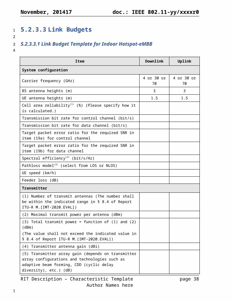
5.2.3.3 Link Budgets5.2.3.3.1 Link Budget Template for Indoor Hotspot-eMBB
Item Downlink Uplink
System configurationCarrier frequency (GHz) 4 or 30 or 70 4 or 30 or 70
BS antenna heights (m) 3 3
UE antenna heights (m) 1.5 1.5
Cell area reliability(1) (%) (Please specify how it is calculated.)
Transmission bit rate for control channel (bit/s)
Transmission bit rate for data channel (bit/s)
Target packet error ratio for the required SNR in item (19a) for control channel
Target packet error ratio for the required SNR in item (19b) for data channel
Spectral efficiency(2) (bit/s/Hz)
Pathloss model(3) (select from LOS or NLOS)
UE speed (km/h)
Feeder loss (dB)
Transmitter(1) Number of transmit antennas (The number shall be within the indicated range in § 8.4 of Report ITU-R M.[IMT-2020.EVAL])
(2) Maximal transmit power per antenna (dBm)
(3) Total transmit power = function of (1) and (2) (dBm)(The value shall not exceed the indicated value in § 8.4 of Report ITU-R M.[IMT-2020.EVAL])
(4) Transmitter antenna gain (dBi)
(5) Transmitter array gain (depends on transmitter array configurations and technologies such as adaptive beam forming, CDD (cyclic delay diversity), etc.) (dB)
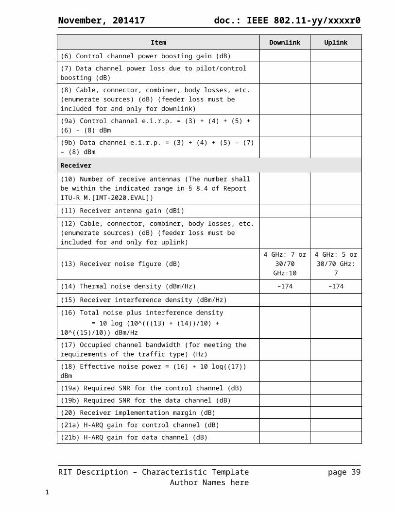
(6) Control channel power boosting gain (dB)
(7) Data channel power loss due to pilot/control boosting (dB)
(8) Cable, connector, combiner, body losses, etc. (enumerate sources) (dB) (feeder loss must be included for and only for downlink)
(9a) Control channel e.i.r.p. = (3) + (4) + (5) + (6) – (8) dBm
(9b) Data channel e.i.r.p. = (3) + (4) + (5) – (7) – (8) dBm
Receiver(10) Number of receive antennas (The number shall be within the indicated range in § 8.4 of Report ITU-R M.[IMT-2020.EVAL])
RIT Description – Characteristic Template page 35 Author Names here
12
34
1
November, 201417 doc.: IEEE 802.11-yy/xxxxr0
Item Downlink Uplink
(11) Receiver antenna gain (dBi)
(12) Cable, connector, combiner, body losses, etc. (enumerate sources) (dB) (feeder loss must be included for and only for uplink)
(13) Receiver noise figure (dB) 4 GHz: 7 or 30/70 GHz:10
4 GHz: 5 or 30/70 GHz: 7
(14) Thermal noise density (dBm/Hz) –174 –174
(15) Receiver interference density (dBm/Hz)
(16) Total noise plus interference density = 10 log (10^(((13) + (14))/10) + 10^((15)/10)) dBm/Hz
(17) Occupied channel bandwidth (for meeting the requirements of the traffic type) (Hz)
(18) Effective noise power = (16) + 10 log((17)) dBm
(19a) Required SNR for the control channel (dB)
(19b) Required SNR for the data channel (dB)
(20) Receiver implementation margin (dB)
(21a) H-ARQ gain for control channel (dB)
(21b) H-ARQ gain for data channel (dB)
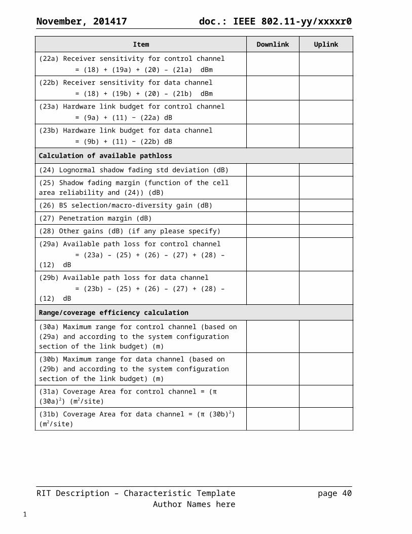
(22a) Receiver sensitivity for control channel = (18) + (19a) + (20) – (21a) dBm
(22b) Receiver sensitivity for data channel = (18) + (19b) + (20) – (21b) dBm
(23a) Hardware link budget for control channel = (9a) + (11) − (22a) dB
(23b) Hardware link budget for data channel = (9b) + (11) − (22b) dB
Calculation of available pathloss(24) Lognormal shadow fading std deviation (dB)
(25) Shadow fading margin (function of the cell area reliability and (24)) (dB)
(26) BS selection/macro-diversity gain (dB)
(27) Penetration margin (dB)
(28) Other gains (dB) (if any please specify)
(29a) Available path loss for control channel = (23a) – (25) + (26) – (27) + (28) – (12) dB
(29b) Available path loss for data channel = (23b) – (25) + (26) – (27) + (28) – (12) dB
Range/coverage efficiency calculation (30a) Maximum range for control channel (based on (29a) and according to the system configuration section of the link budget) (m)
RIT Description – Characteristic Template page 36 Author Names here1
November, 201417 doc.: IEEE 802.11-yy/xxxxr0
Item Downlink Uplink(30b) Maximum range for data channel (based on (29b) and according to the system configuration section of the link budget) (m)
(31a) Coverage Area for control channel = (π (30a)2) (m2/site)
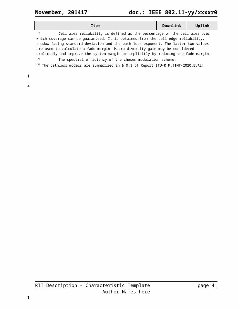
(31b) Coverage Area for data channel = (π (30b)2) (m2/site)(1) Cell area reliability is defined as the percentage of the cell area over which coverage can be guaranteed. It is obtained from the cell edge reliability, shadow fading standard deviation and the path loss exponent. The latter two values are used to calculate a fade margin. Macro diversity gain may be considered explicitly and improve the system margin or implicitly by reducing the fade margin.(2) The spectral efficiency of the chosen modulation scheme.(3) The pathloss models are summarized in § 9.1 of Report ITU-R M.[IMT-2020.EVAL].
RIT Description – Characteristic Template page 37 Author Names here
1
2
1
November, 201417 doc.: IEEE 802.11-yy/xxxxr0
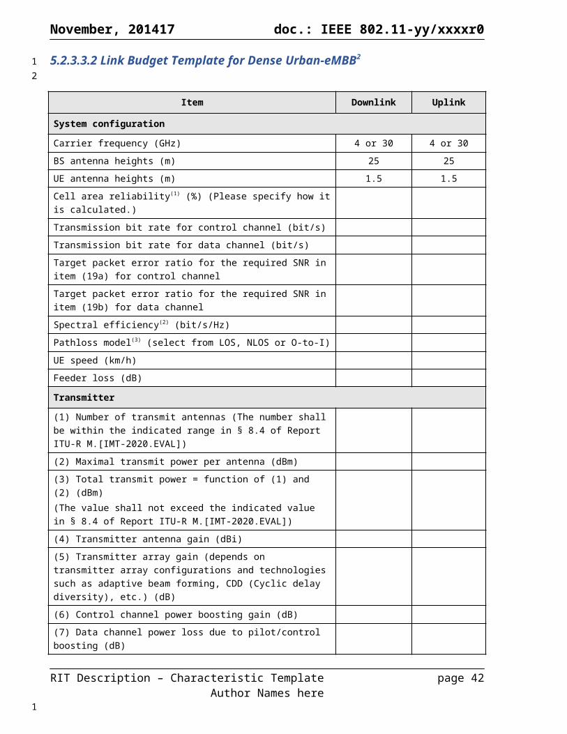
5.2.3.3.2 Link Budget Template for Dense Urban-eMBB2
Item Downlink Uplink
System configurationCarrier frequency (GHz) 4 or 30 4 or 30
BS antenna heights (m) 25 25
UE antenna heights (m) 1.5 1.5
Cell area reliability(1) (%) (Please specify how it is calculated.)
Transmission bit rate for control channel (bit/s)
Transmission bit rate for data channel (bit/s)
Target packet error ratio for the required SNR in item (19a) for control channel
Target packet error ratio for the required SNR in item (19b) for data channel
Spectral efficiency(2) (bit/s/Hz)
Pathloss model(3) (select from LOS, NLOS or O-to-I)
UE speed (km/h)
Feeder loss (dB)
Transmitter(1) Number of transmit antennas (The number shall be within the indicated range in § 8.4 of Report ITU-R M.[IMT-2020.EVAL])
(2) Maximal transmit power per antenna (dBm)
(3) Total transmit power = function of (1) and (2) (dBm) (The value shall not exceed the indicated value in § 8.4 of Report ITU-R M.[IMT-2020.EVAL])
(4) Transmitter antenna gain (dBi)
(5) Transmitter array gain (depends on transmitter array configurations and technologies such as adaptive beam forming, CDD (Cyclic delay diversity), etc.) (dB)
(6) Control channel power boosting gain (dB)
(7) Data channel power loss due to pilot/control boosting (dB)
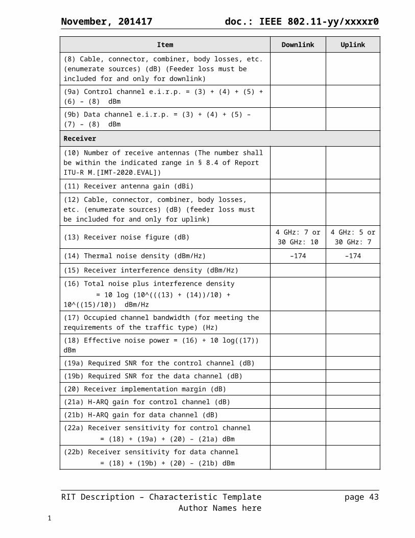
(8) Cable, connector, combiner, body losses, etc. (enumerate sources) (dB) (Feeder loss must be included for and only for downlink)
(9a) Control channel e.i.r.p. = (3) + (4) + (5) + (6) – (8) dBm
(9b) Data channel e.i.r.p. = (3) + (4) + (5) – (7) – (8) dBm
Receiver(10) Number of receive antennas (The number shall be within the indicated range in § 8.4 of Report ITU-R M.[IMT-2020.EVAL])
(11) Receiver antenna gain (dBi)
(12) Cable, connector, combiner, body losses, etc. (enumerate sources) (dB) (feeder loss must be included for and only for uplink)
RIT Description – Characteristic Template page 38 Author Names here
12
1
November, 201417 doc.: IEEE 802.11-yy/xxxxr0
Item Downlink Uplink
(13) Receiver noise figure (dB) 4 GHz: 7 or 30 GHz: 10
4 GHz: 5 or 30 GHz: 7
(14) Thermal noise density (dBm/Hz) –174 –174
(15) Receiver interference density (dBm/Hz)
(16) Total noise plus interference density = 10 log (10^(((13) + (14))/10) + 10^((15)/10)) dBm/Hz
(17) Occupied channel bandwidth (for meeting the requirements of the traffic type) (Hz)
(18) Effective noise power = (16) + 10 log((17)) dBm
(19a) Required SNR for the control channel (dB)
(19b) Required SNR for the data channel (dB)
(20) Receiver implementation margin (dB)
(21a) H-ARQ gain for control channel (dB)
(21b) H-ARQ gain for data channel (dB)
(22a) Receiver sensitivity for control channel = (18) + (19a) + (20) – (21a) dBm
(22b) Receiver sensitivity for data channel = (18) + (19b) + (20) – (21b) dBm
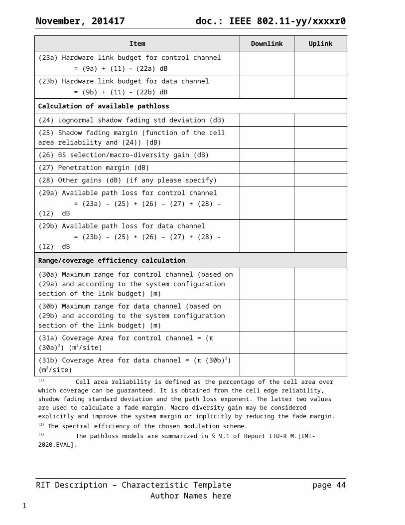
(23a) Hardware link budget for control channel = (9a) + (11) (22a) dB
(23b) Hardware link budget for data channel = (9b) + (11) (22b) dB
Calculation of available pathloss(24) Lognormal shadow fading std deviation (dB)
(25) Shadow fading margin (function of the cell area reliability and (24)) (dB)
(26) BS selection/macro-diversity gain (dB)
(27) Penetration margin (dB)
(28) Other gains (dB) (if any please specify)
(29a) Available path loss for control channel = (23a) – (25) + (26) – (27) + (28) – (12) dB
(29b) Available path loss for data channel = (23b) – (25) + (26) – (27) + (28) – (12) dB
Range/coverage efficiency calculation(30a) Maximum range for control channel (based on (29a) and according to the system configuration section of the link budget) (m)
(30b) Maximum range for data channel (based on (29b) and according to the system configuration section of the link budget) (m)
(31a) Coverage Area for control channel = (π (30a)2) (m2/site)
(31b) Coverage Area for data channel = (π (30b)2) (m2/site)
RIT Description – Characteristic Template page 39 Author Names here1
November, 201417 doc.: IEEE 802.11-yy/xxxxr0
Item Downlink Uplink(1) Cell area reliability is defined as the percentage of the cell area over which coverage can be guaranteed. It is obtained from the cell edge reliability, shadow fading standard deviation and the path loss exponent. The latter two values are used to calculate a fade margin. Macro diversity gain may be considered explicitly and improve the system margin or implicitly by reducing the fade margin.(2) The spectral efficiency of the chosen modulation scheme.(3) The pathloss models are summarized in § 9.1 of Report ITU-R M.[IMT-2020.EVAL].
RIT Description – Characteristic Template page 40 Author Names here
1
2
1
November, 201417 doc.: IEEE 802.11-yy/xxxxr0
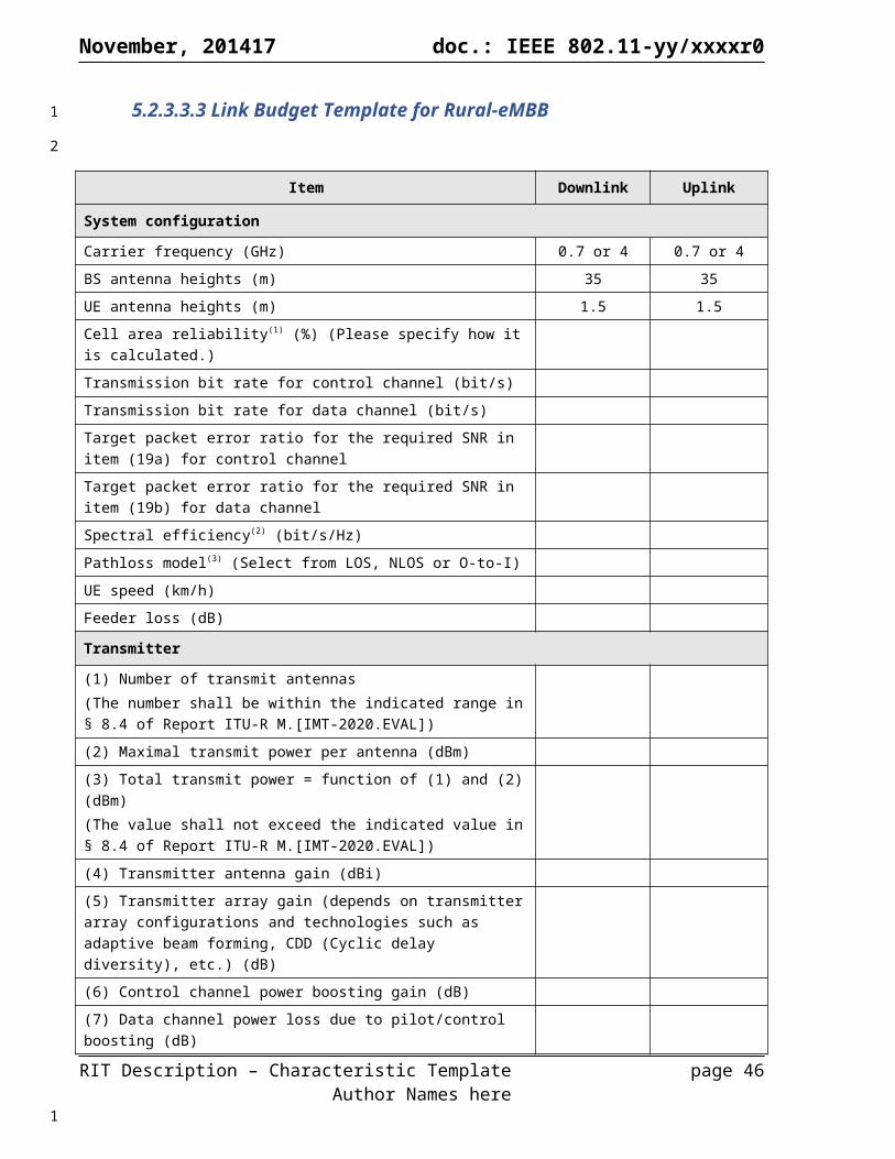
5.2.3.3.3 Link Budget Template for Rural-eMBB
Item Downlink Uplink
System configurationCarrier frequency (GHz) 0.7 or 4 0.7 or 4
BS antenna heights (m) 35 35
UE antenna heights (m) 1.5 1.5
Cell area reliability(1) (%) (Please specify how it is calculated.)
Transmission bit rate for control channel (bit/s)
Transmission bit rate for data channel (bit/s)
Target packet error ratio for the required SNR in item (19a) for control channel
Target packet error ratio for the required SNR in item (19b) for data channel
Spectral efficiency(2) (bit/s/Hz)
Pathloss model(3) (Select from LOS, NLOS or O-to-I)
UE speed (km/h)
Feeder loss (dB)
Transmitter(1) Number of transmit antennas (The number shall be within the indicated range in § 8.4 of Report ITU-R M.[IMT-2020.EVAL])
(2) Maximal transmit power per antenna (dBm)
(3) Total transmit power = function of (1) and (2) (dBm) (The value shall not exceed the indicated value in § 8.4 of Report ITU-R M.[IMT-2020.EVAL])
(4) Transmitter antenna gain (dBi)
(5) Transmitter array gain (depends on transmitter array configurations and technologies such as adaptive beam forming, CDD (Cyclic delay diversity), etc.) (dB)
(6) Control channel power boosting gain (dB)
(7) Data channel power loss due to pilot/control boosting (dB)
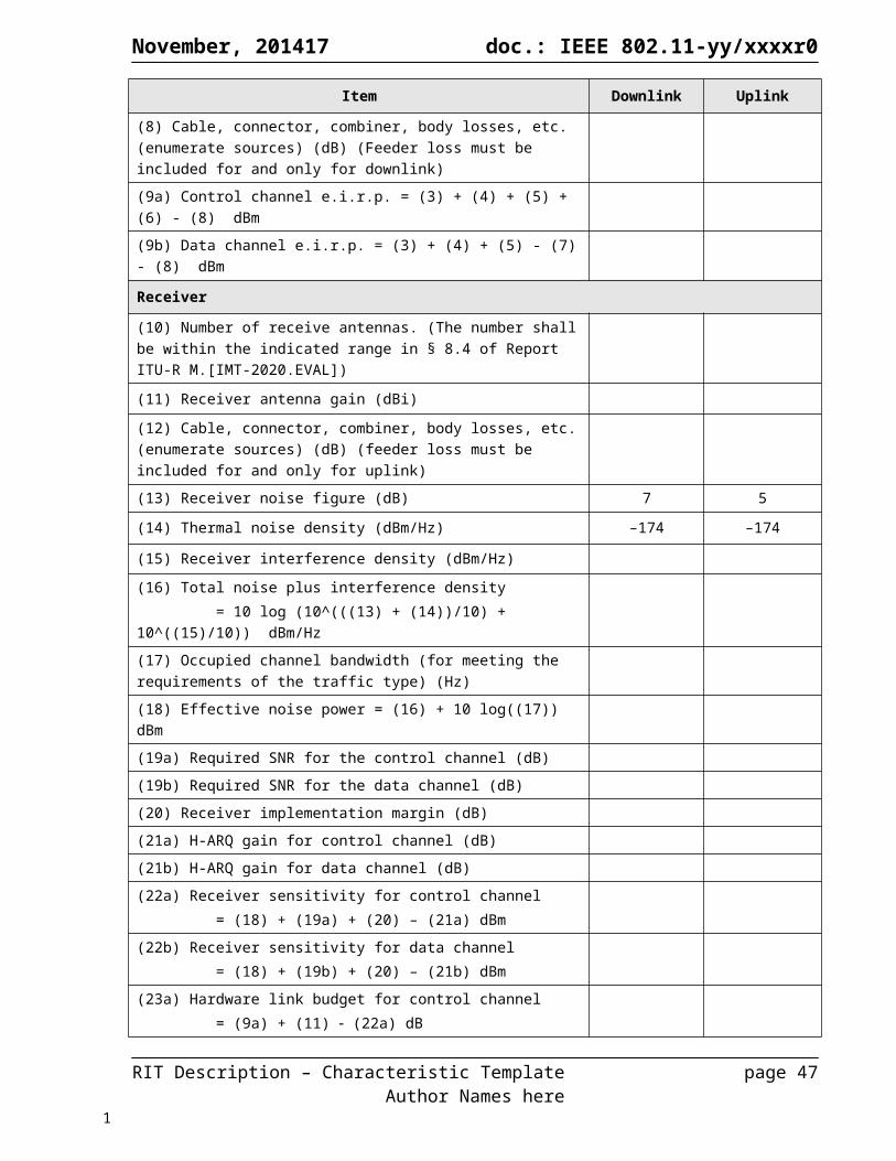
(8) Cable, connector, combiner, body losses, etc. (enumerate sources) (dB) (Feeder loss must be included for and only for downlink)
(9a) Control channel e.i.r.p. = (3) + (4) + (5) + (6) - (8) dBm
(9b) Data channel e.i.r.p. = (3) + (4) + (5) - (7) - (8) dBm
Receiver(10) Number of receive antennas. (The number shall be within the indicated range in § 8.4 of Report ITU-R M.[IMT-2020.EVAL])
(11) Receiver antenna gain (dBi)
RIT Description – Characteristic Template page 41 Author Names here
1
2
1
November, 201417 doc.: IEEE 802.11-yy/xxxxr0
Item Downlink Uplink(12) Cable, connector, combiner, body losses, etc. (enumerate sources) (dB) (feeder loss must be included for and only for uplink)
(13) Receiver noise figure (dB) 7 5
(14) Thermal noise density (dBm/Hz) –174 –174
(15) Receiver interference density (dBm/Hz)
(16) Total noise plus interference density = 10 log (10^(((13) + (14))/10) + 10^((15)/10)) dBm/Hz
(17) Occupied channel bandwidth (for meeting the requirements of the traffic type) (Hz)
(18) Effective noise power = (16) + 10 log((17)) dBm
(19a) Required SNR for the control channel (dB)
(19b) Required SNR for the data channel (dB)
(20) Receiver implementation margin (dB)
(21a) H-ARQ gain for control channel (dB)
(21b) H-ARQ gain for data channel (dB)
(22a) Receiver sensitivity for control channel = (18) + (19a) + (20) – (21a) dBm
(22b) Receiver sensitivity for data channel = (18) + (19b) + (20) – (21b) dBm
(23a) Hardware link budget for control channel = (9a) + (11) (22a) dB
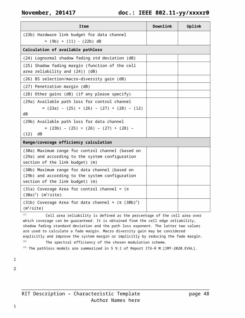
(23b) Hardware link budget for data channel = (9b) + (11) (22b) dB
Calculation of available pathloss(24) Lognormal shadow fading std deviation (dB)
(25) Shadow fading margin (function of the cell area reliability and (24)) (dB)
(26) BS selection/macro-diversity gain (dB)
(27) Penetration margin (dB)
(28) Other gains (dB) (if any please specify)
(29a) Available path loss for control channel = (23a) – (25) + (26) – (27) + (28) – (12) dB
(29b) Available path loss for data channel = (23b) – (25) + (26) – (27) + (28) – (12) dB
Range/coverage efficiency calculation(30a) Maximum range for control channel (based on (29a) and according to the system configuration section of the link budget) (m)
(30b) Maximum range for data channel (based on (29b) and according to the system configuration section of the link budget) (m)
(31a) Coverage Area for control channel = (π (30a)2) (m2/site)
RIT Description – Characteristic Template page 42 Author Names here1
November, 201417 doc.: IEEE 802.11-yy/xxxxr0
Item Downlink Uplink(31b) Coverage Area for data channel = (π (30b)2) (m2/site)(1) Cell area reliability is defined as the percentage of the cell area over which coverage can be guaranteed. It is obtained from the cell edge reliability, shadow fading standard deviation and the path loss exponent. The latter two values are used to calculate a fade margin. Macro diversity gain may be considered explicitly and improve the system margin or implicitly by reducing the fade margin.(2) The spectral efficiency of the chosen modulation scheme.(3) The pathloss models are summarized in § 9.1 of Report ITU-R M.[IMT-2020.EVAL].
RIT Description – Characteristic Template page 43 Author Names here
1
2
1
November, 201417 doc.: IEEE 802.11-yy/xxxxr0
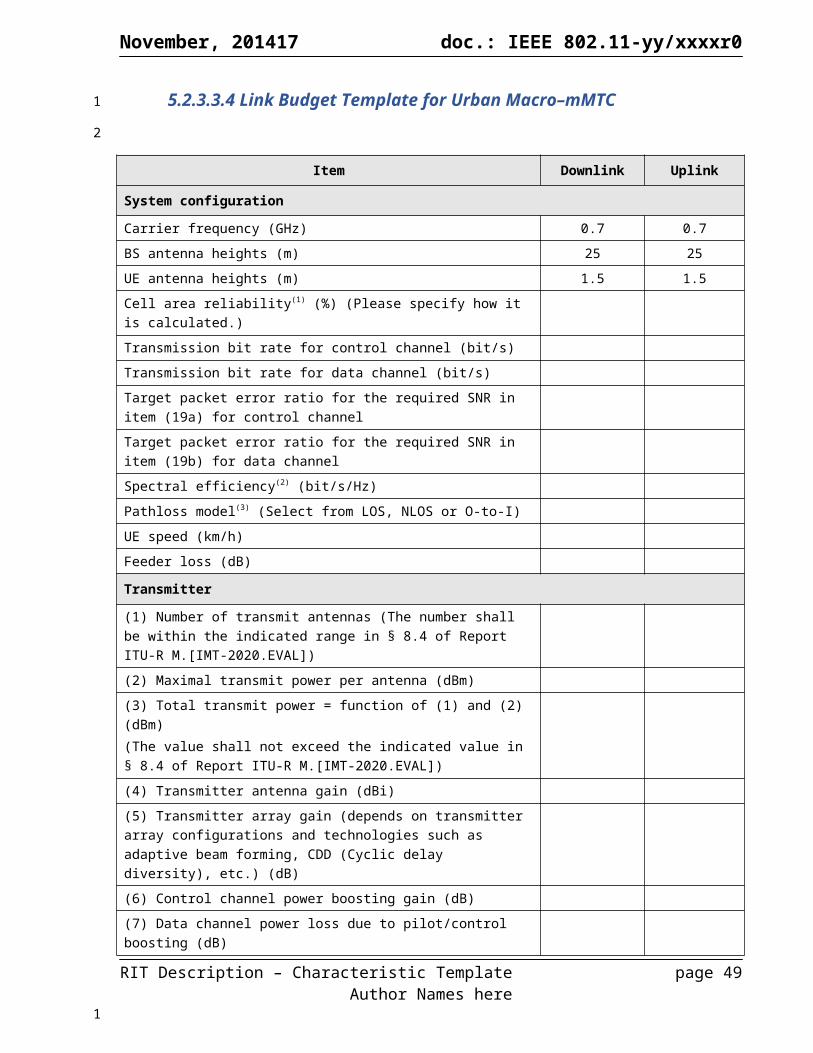
5.2.3.3.4 Link Budget Template for Urban Macro–mMTC
Item Downlink Uplink
System configurationCarrier frequency (GHz) 0.7 0.7
BS antenna heights (m) 25 25
UE antenna heights (m) 1.5 1.5
Cell area reliability(1) (%) (Please specify how it is calculated.)
Transmission bit rate for control channel (bit/s)
Transmission bit rate for data channel (bit/s)
Target packet error ratio for the required SNR in item (19a) for control channel
Target packet error ratio for the required SNR in item (19b) for data channel
Spectral efficiency(2) (bit/s/Hz)
Pathloss model(3) (Select from LOS, NLOS or O-to-I)
UE speed (km/h)
Feeder loss (dB)
Transmitter(1) Number of transmit antennas (The number shall be within the indicated range in § 8.4 of Report ITU-R M.[IMT-2020.EVAL])
(2) Maximal transmit power per antenna (dBm)
(3) Total transmit power = function of (1) and (2) (dBm) (The value shall not exceed the indicated value in § 8.4 of Report ITU-R M.[IMT-2020.EVAL])
(4) Transmitter antenna gain (dBi)
(5) Transmitter array gain (depends on transmitter array configurations and technologies such as adaptive beam forming, CDD (Cyclic delay diversity), etc.) (dB)
(6) Control channel power boosting gain (dB)
(7) Data channel power loss due to pilot/control boosting (dB)
(8) Cable, connector, combiner, body losses, etc. (enumerate sources) (dB) (feeder loss must be included for and only for downlink)
(9a) Control channel e.i.r.p. = (3) + (4) + (5) + (6) – (8) dBm
(9b) Data channel e.i.r.p. = (3) + (4) + (5) – (7) – (8) dBm
Receiver(10) Number of receive antennas (The number shall be within the indicated range in § 8.4 of Report ITU-R M.[IMT-2020.EVAL])
(11) Receiver antenna gain (dBi)
(12) Cable, connector, combiner, body losses, etc. (enumerate sources) (dB) (feeder loss must be included for and only for uplink)
RIT Description – Characteristic Template page 44 Author Names here
1
2
1

November, 201417 doc.: IEEE 802.11-yy/xxxxr0
Item Downlink Uplink(13) Receiver noise figure (dB) 7 5
(14) Thermal noise density (dBm/Hz) –174 –174
(15) Receiver interference density (dBm/Hz)
(16) Total noise plus interference density = 10 log (10^(((13)+(14))/10) + 10^((15)/10)) dBm/Hz
(17) Occupied channel bandwidth (for meeting the requirements of the traffic type) (Hz)
(18) Effective noise power = (16) + 10 log((17)) dBm
(19a) Required SNR for the control channel (dB)
(19b) Required SNR for the data channel (dB)
(20) Receiver implementation margin (dB)
(21a) H-ARQ gain for control channel (dB)
(21b) H-ARQ gain for data channel (dB)
(22a) Receiver sensitivity for control channel = (18) + (19a) + (20) – (21a) dBm
(22b) Receiver sensitivity for data channel = (18) + (19b) + (20) – (21b) dBm
(23a) Hardware link budget for control channel = (9a) + (11) - (22a) dB
(23b) Hardware link budget for data channel = (9b) + (11) - (22b) dB
Calculation of available pathloss(24) Lognormal shadow fading std deviation (dB)
(25) Shadow fading margin (function of the cell area reliability and (24)) (dB)
(26) BS selection/macro-diversity gain (dB)
(27) Penetration margin (dB)
(28) Other gains (dB) (if any please specify)
(29a) Available path loss for control channel = (23a) – (25) + (26) – (27) + (28) – (12) dB
(29b) Available path loss for data channel = (23b) – (25) + (26) – (27) + (28) – (12) dB
Range/coverage efficiency calculation(30a) Maximum range for control channel (based on (29a) and according to the system configuration section of the link budget) (m)
(30b) Maximum range for data channel (based on (29b) and according to the system configuration section of the link budget) (m)
(31a) Coverage Area for control channel = (π (30a)2) (m2/site)
(31b) Coverage Area for data channel = (π (30b)2) (m2/site)
RIT Description – Characteristic Template page 45 Author Names here1
November, 201417 doc.: IEEE 802.11-yy/xxxxr0
Item Downlink Uplink(1) Cell area reliability is defined as the percentage of the cell area over which coverage can be guaranteed. It is obtained from the cell edge reliability, shadow fading standard deviation and the path loss exponent. The latter two values are used to calculate a fade margin. Macro diversity gain may be considered explicitly and improve the system margin or implicitly by reducing the fade margin.(2) The spectral efficiency of the chosen modulation scheme.(3) The pathloss models are summarized in § 9.1 of Report ITU-R M.[IMT-2020.EVAL].
RIT Description – Characteristic Template page 46 Author Names here
1
2
1
November, 201417 doc.: IEEE 802.11-yy/xxxxr0
5.2.3.3.5 Link Budget Template for Urban Macro–URLLC
Item Downlink Uplink
System configurationCarrier frequency (GHz) 0.7 or 4 0.7 or 4
BS antenna heights (m) 25 25
UE antenna heights (m) 1.5 1.5
Cell area reliability(1) (%) (Please specify how it is calculated.)
Transmission bit rate for control channel (bit/s)
Transmission bit rate for data channel (bit/s)
Target packet error ratio for the required SNR in item (19a) for control channel
Target packet error ratio for the required SNR in item (19b) for data channel
Spectral efficiency(2) (bit/s/Hz)
Pathloss model(3) (Select from LOS, NLOS or O-to-I)
UE speed (km/h)
Feeder loss (dB)
Transmitter(1) Number of transmit antennas (The number shall be within the indicated range in § 8.4 of Report ITU-R M.[IMT-2020.EVAL])
(2) Maximal transmit power per antenna (dBm)
(3) Total transmit power = function of (1) and (2) (dBm) (The value shall not exceed the indicated value in § 8.4 of Report ITU-R M.[IMT-2020.EVAL])
(4) Transmitter antenna gain (dBi)
(5) Transmitter array gain (depends on transmitter array configurations and technologies such as adaptive beam forming, CDD (cyclic delay diversity), etc.) (dB)
(6) Control channel power boosting gain (dB)
(7) Data channel power loss due to pilot/control boosting (dB)
(8) Cable, connector, combiner, body losses, etc. (enumerate sources) (dB) (Feeder loss must be included for and only for downlink)
(9a) Control channel e.i.r.p. = (3) + (4) + (5) + (6) - (8) dBm
(9b) Data channel e.i.r.p. = (3) + (4) + (5) - (7) - (8) dBm
Receiver(10) Number of receive antennas (The number shall be within the indicated range in § 8.4 of Report ITU-R M.[IMT-2020.EVAL])
(11) Receiver antenna gain (dBi)
RIT Description – Characteristic Template page 47 Author Names here
1
2
1
November, 201417 doc.: IEEE 802.11-yy/xxxxr0
Item Downlink Uplink(12) Cable, connector, combiner, body losses, etc. (enumerate sources) (dB) (Feeder loss must be included for and only for uplink)
(13) Receiver noise figure (dB) 7 5
(14) Thermal noise density (dBm/Hz) –174 –174
(15) Receiver interference density (dBm/Hz)
(16) Total noise plus interference density = 10 log (10^(((13) + (14))/10) + 10^((15)/10)) dBm/Hz
(17) Occupied channel bandwidth (for meeting the requirements of the traffic type) (Hz)
(18) Effective noise power = (16) + 10 log((17)) dBm
(19a) Required SNR for the control channel (dB)
(19b) Required SNR for the data channel (dB)
(20) Receiver implementation margin (dB)
(21a) H-ARQ gain for control channel (dB)
(21b) H-ARQ gain for data channel (dB)
(22a) Receiver sensitivity for control channel = (18) + (19a) + (20) – (21a) dBm
(22b) Receiver sensitivity for data channel = (18) + (19b) + (20) – (21b) dBm
(23a) Hardware link budget for control channel = (9a) + (11) - (22a) dB
(23b) Hardware link budget for data channel = (9b) + (11) - (22b) dB
Calculation of available pathloss(24) Lognormal shadow fading std deviation (dB)
(25) Shadow fading margin (function of the cell area reliability and (24)) (dB)
(26) BS selection/macro-diversity gain (dB)
(27) Penetration margin (dB)
(28) Other gains (dB) (if any please specify)
(29a) Available path loss for control channel = (23a) – (25) + (26) – (27) + (28) – (12) dB
(29b) Available path loss for data channel = (23b) – (25) + (26) – (27) + (28) – (12) dB
Range/coverage efficiency calculation(30a) Maximum range for control channel (based on (29a) and according to the system configuration section of the link budget) (m)
(30b) Maximum range for data channel (based on (29b) and according to the system configuration section of the link budget) (m)
(31a) Coverage Area for control channel = (π (30a)2) (m2/site)
RIT Description – Characteristic Template page 48 Author Names here1
November, 201417 doc.: IEEE 802.11-yy/xxxxr0
Item Downlink Uplink(31b) Coverage Area for data channel = (π (30b)2) (m2/site)(1) Cell area reliability is defined as the percentage of the cell area over which coverage can be guaranteed. It is obtained from the cell edge reliability, shadow fading standard deviation and the path loss exponent. The latter two values are used to calculate a fade margin. Macro diversity gain may be considered explicitly and improve the system margin or implicitly by reducing the fade margin.(2) The spectral efficiency of the chosen modulation scheme.(3) The pathloss models are summarized in § 9.1 of Report ITU-R M.[IMT-2020.EVAL].
RIT Description – Characteristic Template page 49 Author Names here
1
1