Embed Size (px)
Citation preview
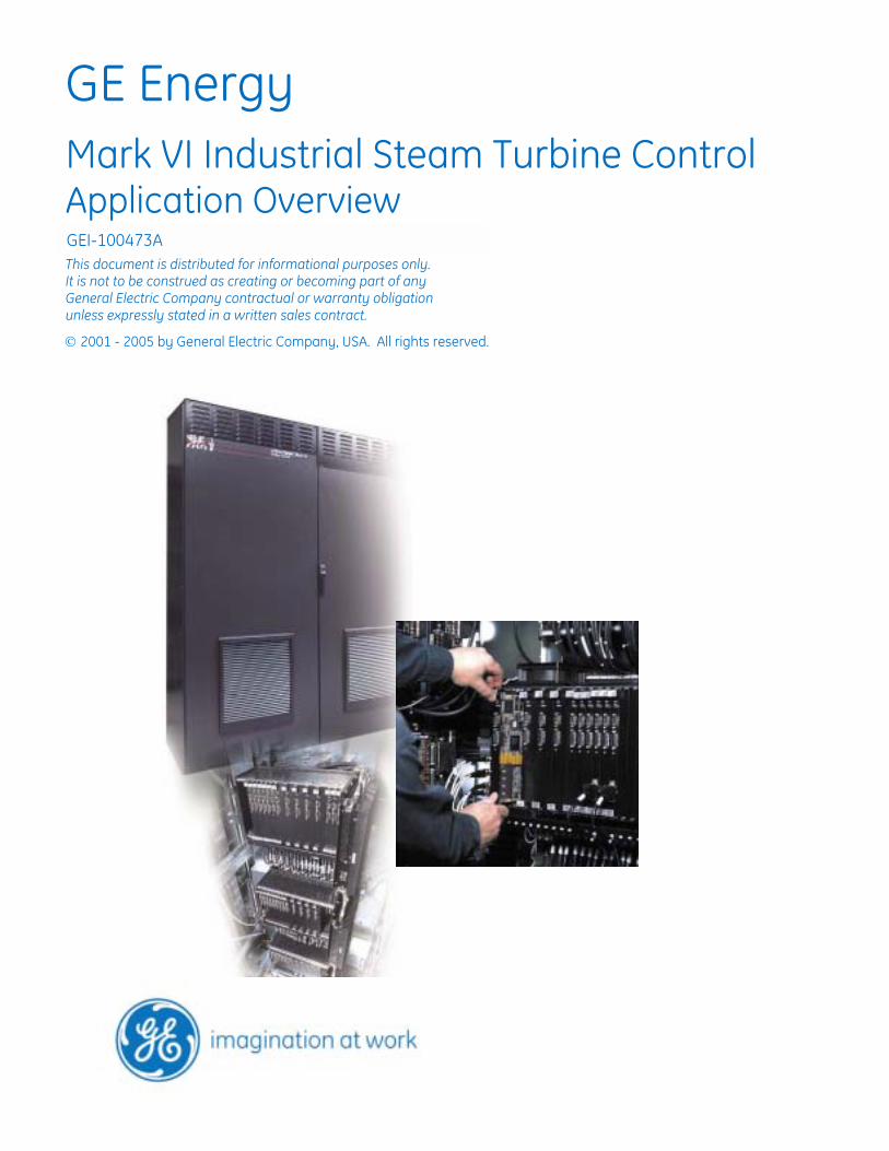
GE Energy
Mark VI Industrial Steam Turbine Control Application Overview
This document is distributed for informational purposes only. It is not to be construed as creating or becoming part of any General Electric Company contractual or warranty obligation unless expressly stated in a written sales contract.
2001 - 2005 by General Electric Company, USA. All rights reserved.
GEI-100473A
Section Page
Control System............................................................................................................3 I/O Interface ................................................................................................................4 Control Functions ........................................................................................................6 Protection ..................................................................................................................10 Accessory Subsystems...............................................................................................12 Operator Screens .......................................................................................................13 Packaging ..................................................................................................................15 Power Requirements (typical) ...................................................................................16 Control Drawings ......................................................................................................17
CIMPLICITY is a registered trademark of GE Fanuc Automation North America, Inc. Ethernet is a registered trademark of Xerox Corporation. Microsoft and Windows are registered trademarks of Microsoft Corporation. Proximitor is a registered trademark of Bently Nevada.
Control System The GE Industrial Steam Turbine Control (ISTC) is part of the Mark VI turbine controls. The ISTC provides basic control functions. These functions can then be expanded in small increments for various levels of control, protection, and monitoring for the turbine, the auxiliary systems, and the driven load equipment (generator / compressor / pump).
The control can be expanded from a governor to a complete control, protection, and monitoring system.
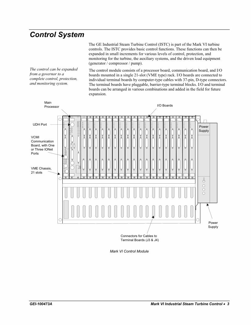
The control module consists of a processor board, communication board, and I/O boards mounted in a single 21-slot (VME type) rack. I/O boards are connected to individual terminal boards by computer-type cables with 37-pin, D-type connectors. The terminal boards have pluggable, barrier-type terminal blocks. I/O and terminal boards can be arranged in various combinations and added in the field for future expansion.
x x x x
x
x
x
x
x
x
x
x
x
x
x
x
x
x
x
x
x
x
x
x
x
x
x
x
x
x
x
x
x
xx
x
x
VME Chassis,21 slots
PowerSupply
Connectors for Cables toTerminal Boards (J3 & J4)
VCMICommunicationBoard, with Oneor Three IONetPorts
MainProcessor I/O Boards
PowerSupply
UDH Port
Mark VI Control Module
GEI-100473A Mark VI Industrial Steam Turbine Control • 3
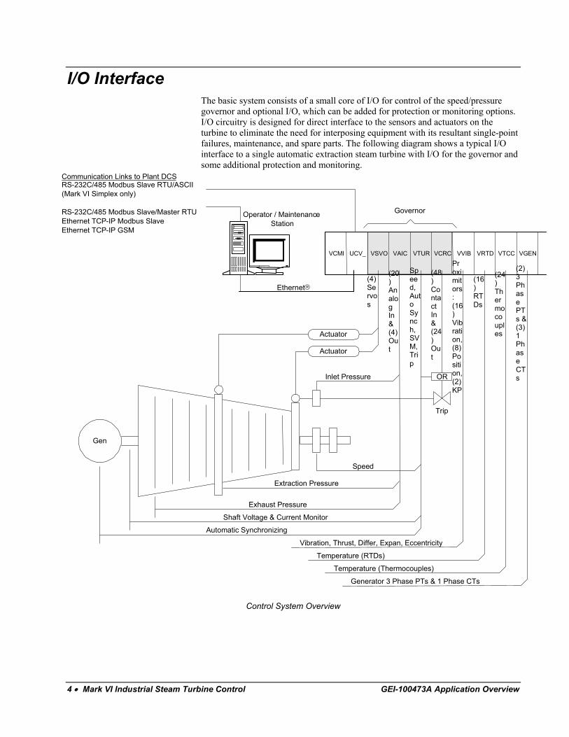
I/O Interface The basic system consists of a small core of I/O for control of the speed/pressure governor and optional I/O, which can be added for protection or monitoring options. I/O circuitry is designed for direct interface to the sensors and actuators on the turbine to eliminate the need for interposing equipment with its resultant single-point failures, maintenance, and spare parts. The following diagram shows a typical I/O interface to a single automatic extraction steam turbine with I/O for the governor and some additional protection and monitoring.
VCMI UCV_ VTURVAICVSVO VVIB VGENVTCCVRTDVCRC
GovernorOperator / MaintenanceStation
RS-232C/485 Modbus Slave RTU/ASCII(Mark VI Simplex only)
RS-232C/485 Modbus Slave/Master RTUEthernet TCP-IP Modbus SlaveEthernet TCP-IP GSM
Communication Links to Plant DCS
Ethernet
Gen
Actuator
Actuator
Inlet Pressure
Trip
Speed
Extraction Pressure
Exhaust Pressure
Shaft Voltage & Current Monitor
Automatic Synchronizing
OR
(20)AnalogIn&(4)Out
(4)Servos
Speed,AutoSynch,SVM,Trip
(48)ContactIn&(24)Out
Proximitors:(16)Vibration,(8)Position,(2)KP
(16)RTDs
(24)Thermocouples
(2)3PhasePTs &(3)1PhaseCTs
Vibration, Thrust, Differ, Expan, Eccentricity
Temperature (RTDs)
Temperature (Thermocouples)
Generator 3 Phase PTs & 1 Phase CTs
Control System Overview
4 • Mark VI Industrial Steam Turbine Control GEI-100473A Application Overview
Valve Interface - Regulation of the control valve loop is provided in software with a direct interface to the servo valve actuator and the Linear Variable Differential Transformer (LVDT) valve position feedback. Bi-polar current outputs are provided for 10, 20, 40, 80, 120 mA ranges. A 7 Vrms, 3.2 kHz excitation signal for the LVDT is provided by the turbine control, and the LVDT feedback is 0 to 7.0 Vrms position feedback. 0 to 20 mA and 0 to 200 mA outputs are provided for interface to I/P transducers or valve positioners.
Speed Control Inputs - Three passive, magnetic, speed-sensor inputs (2-14 kHz) are provided. The median value is used for speed control and primary overspeed protection. Circuit sensitivity allows detection of 2 rpm speed on a 60-tooth wheel to determine whether the turbine is stopped or on turning gear.
Emergency overspeed protection is provided by either a mechanical overspeed bolt or a separate set of magnetic speed sensors, which are monitored by a separate and independent emergency overspeed module. Diagnostic tests of the emergency overspeed module can be started and monitored from the operator interface or from a plant Distributed Control System (DCS) while the turbine is running or shutdown.
Synchronizing - Automatic synchronizing is available through single-phase potential transformer (PT) inputs from the generator and line. The control matches the turbine speed to the line frequency and the generator and line voltages. An automatic command to close the breaker is issued when the breaker is predicted to close within the phase-slip window. A normally open contact on the breaker (not an auxiliary relay) is monitored to measure the actual breaker closure time used to update the database. Manual synchronizing is provided from a synch scope display on a Human-Machine Interface (HMI) operator interface.
Shaft Voltage and Current Monitor - Bearings can be damaged by the flow of electrical current through the bearing. This can occur due to a static voltage buildup caused by water droplets being thrown off the last stage buckets in steam turbines or to ac voltage on the shaft caused by ac ripple on the dc generator field. Voltage can build up across the oil film of bearings until a discharge occurs. Repeated discharge and arcing can cause a pitted and roughened bearing surface that eventually fails through accelerated mechanical wear. The turbine control can continuously monitor the shaft to ground voltage and current and alarm excessive levels. Test circuits are provided to check the alarm functions and the continuity of wiring to the brush assembly mounted between the turbine and the generator.
Twenty analog inputs and four analog outputs included in base, additional optional.
Analog I/O - All inputs can monitor 4-20 mA (250 Ω) that can be configured for self-powered, differential inputs, or as sensors that use a +24 V dc supply from the turbine control. Two of the inputs are designed for 0-1 mA inputs with 5,000 ohm input impedance, and eight of the inputs are designed for ±5, 10 V dc inputs. Each set of two analog outputs consists of one 4-20 mA output (500 Ω maximum) and one output that can be configured for either 4-20 mA output or 0-200 mA output (50 Ω maximum).
Forty-eight contact inputs included in base, additional optional.
Contact Inputs - All contact inputs are optically isolated and time-stamped to within 1 ms. This built-in Sequence of Events (SOE) monitor can be observed with a HMI operator / maintenance leave station. Dry contacts can be powered from a floating 125 V dc supply from the control, which is fuse-isolated and current-limited in the turbine control. Optional 24 V dc, 90-132 Vrms, 190-264 Vrms (47-63 Hz) contact input monitoring is also available.
Twenty-four contact outputs included in base, additional optional.
Contact Outputs - Plug-in type magnetic relays provide a dry, form C contact output from each relay.
GEI-100473A Mark VI Industrial Steam Turbine Control • 5
Optional VVIB board and terminal boards.
A direct plug connection is available from the ISTC to a Bently Nevada 3500 monitor.
Proximitor Inputs - A direct interface can be provided from the turbine control to Bently-Nevada Proximitors for vibration protection, thrust wear protection, differential expansion, and eccentricity monitoring. The 1X and unfiltered vibration levels and the 1X vibration phase angle are displayed. -24 V dc is supplied from the ISTC to each Proximitor. The composite and 1X vibration levels are displayed, as well as the 1X phase angle. An active isolation amplifier is provided on each terminal board to buffer the sensor signal from BNC connectors on the board. These connectors can be used to access real-time data by remote vibration analysis equipment.
Optional 24 per VTTC and terminal board.
Thermocouple Inputs - These inputs can be grounded or ungrounded. Software linearization is provided for type E, J, K, or T thermocouples.
Optional 16 per VRTD board and terminal board.
RTD Inputs - Inputs can be grounded or ungrounded, and software linearization is provided for 10 Ω copper, 100/200 Ω platinum, or 120 Ω nickel RTDs.
Optional VGEN board and terminal board.
Three-phase PT and current transformers (CT) monitoring - The turbine control can provide a direct interface to three-phase PTs from the generator and line, and CTs from the generator, including the neutral. Megawatts, VARs, and power-factor values can be calculated from the PT and CT inputs. These values can then be used as feedback for control functions.
Control Functions Each retrofit is reviewed for auto-turning gear control or manual engage from the control room.
Turning Gear Control - The Mark VI can interface with the turning gear system in either a manual or an automatic mode. In manual mode, the operator engages the turning gear through the operator interface. In automatic mode, the turning gear is automatically engaged when the turbine speed is below a safe engaging speed.
Speed Control - The speed control system controls the turbine’s speed and load by operating in response to its actual speed signal and called-for speed reference. Passive magnetic type probes are used in conjunction with a multi-toothed wheel on the steam turbine shaft to sense rotational speed. Speed control prior to generator synchronization is Proportional Plus Integral (PPI). After synchronization the control is proportional only. The speed regulation is normally 5%.
Minor variations in desired plant frequency can be obtained by adjustment of the speed setpoint.
Isochronous Control - In some applications, a unit is required either to operate under isolated conditions continuously or occasionally to maintain plant frequency. Once placed in service, usually from a tie line status contact, the isochronous speed control function resets speed to its setpoint following load variations by automatically manipulating on the load setpoint. Therefore, it maintains a constant steady-state speed and eliminates the operator continuously changing the load setpoint to match the load being carried.
Speed Wobulator - During startup, some units may require a speed wobulator incorporated in the speed control to slowly vary turbine speed above and below the speed setpoint. The wobulator prevents the turbine from running at a constant speed near critical bucket resonances.
Speed /Frequency Matching - The speed-matching function sets the steam turbine at synchronous speed at the completion of the start-up routine.
Synchronization - Automatic and manual synchronization are available in the Mark VI. Synchronization check protection may also be provided for backup protection.
6 • Mark VI Industrial Steam Turbine Control GEI-100473A Application Overview
Automatic Synchronization is performed with phase-slip windows in the control modules. The control system matches speed and voltage, and issues a command to close the breaker based on a calculated breaker closure time. Diagnostics monitor the actual breaker closure time and self-correct each time the breaker closes. A monitor mode allows automatic speed and voltage matching, but inhibits closing the breaker for the operator’s inspection.
Manual Synchronization can be initiated by operating a RAISE/LOWER load setpoint command either on the generator control panel or from the turbine control synchronization screen located on the operator interface.
Synchronization Check Protection provides backup to the automatic and manual synchronization systems. This function is performed in the protection <P> module.
When the unit is synchronizing, the load setpoint also functions as a fine speed adjustment.
Load Control - The load setpoint is an open loop command that is an opening reference to the control valves. The name implies that it is load control; however, it can only contribute to the demand for steam flow.
Regulation of the valve reference and the position feedback is performed in software.
Valve Control - Valve interface is implemented with LVDT/R and servo loops or 4-20 mA valve interface. Each interface includes an auto-calibrate display for the valves and hardware diagnostics.
Main Stop Valve(s) are solenoid-operated and allow the turbine control valve(s) to be isolated from the high-pressure steam. It also provides, in conjunction with the control valve(s), redundant protection against overspeed through two independent lines of defense.
Inlet Control Valve(s) regulates the high-pressure steam flow into the turbine and respond to speed/load control commands.
Extraction Control Valve(s) regulate the steam flow into or out of the turbine down stream of the inlet control valve by responding to the pressure and speed/load control commands.
Automatic Extraction - The extraction control algorithm balances the turbine under various conditions. Unlike older systems, the Mark VI control allows the operator to bumpless transfer between operating modes. For example, to transfer from speed/load and extraction to inlet pressure and extraction control, the operator selected the desired mode. The Mark VI calculates the inlet pressure setpoint required to maintain the current inlet valve position in order to provide a bumpless transfer.
Single automatic extraction units are normally used to control speed/load and one process pressure simultaneously. Both the inlet and the extraction control valves respond to speed/load control commands to change the steam flow to each section equally to control speed/load without affecting extraction flow, such as pressure. The inlet and extraction control valves respond to control commands to control extraction pressure without affecting speed/load. This is accomplished by moving the valves in opposite directions in such proportions that the change in load in the inlet section is balanced by an opposite change in load in the exhaust section. The difference between the inlet and exhaust steam flow is the extraction steam.
GEI-100473A Mark VI Industrial Steam Turbine Control • 7
Extraction Flow control - Under certain plant conditions, it is desirable to operate the turbine extraction at a fixed flow rather than controlling the extraction pressure. In this mode of operation, the extraction pressure setpoint is changed to a level higher than the stage pressure and the flow control setpoint is reduced to fix the extraction flow reference signal. Extraction flow remains constant in this operating mode, providing extraction header pressure is maintained by another plant control system. It is important to remember that this method of control will allow the control valves to reduce flow if the stage pressure goes above the turbine maximum design.
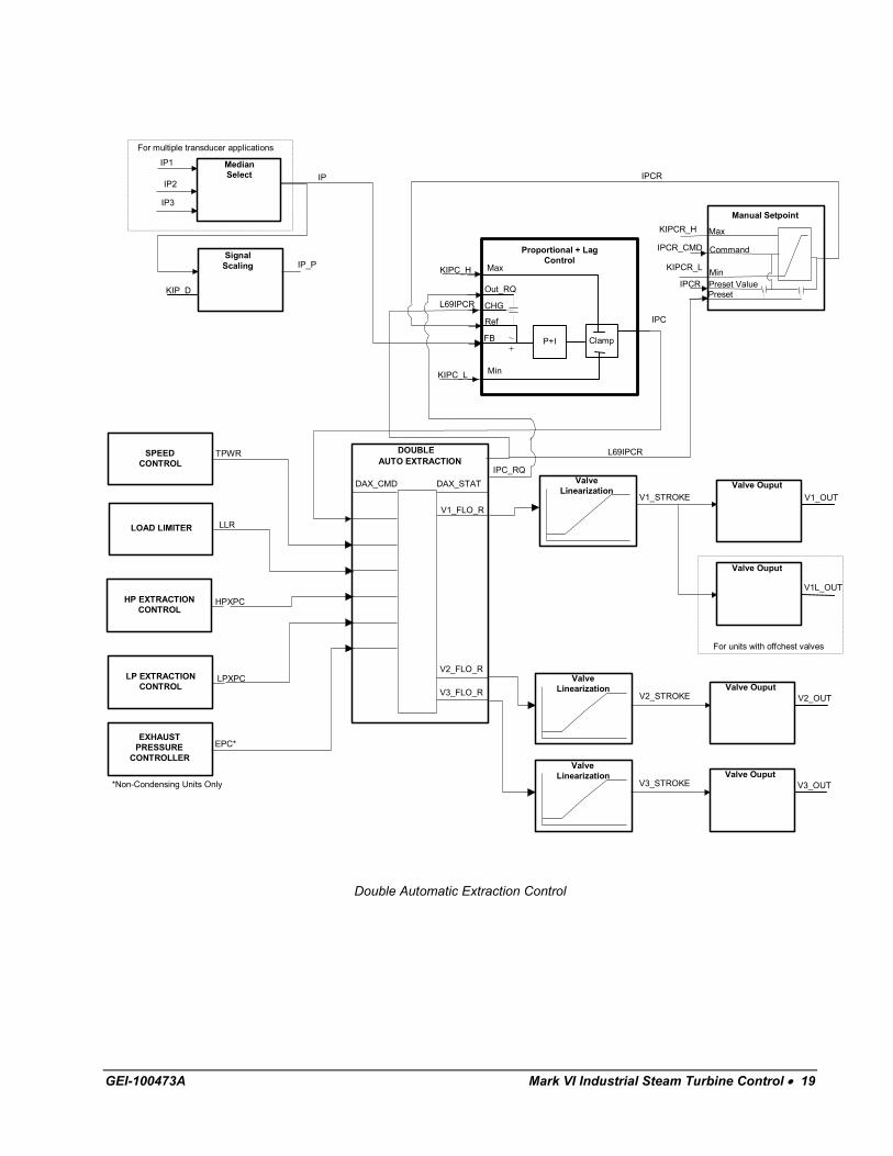
Double Automatic Extraction - These units are used to control speed/load and two extraction process pressures simultaneously. In some cases, such units are used to control three process pressures, two extractions, and either inlet or exhaust pressure such as for non-condensing.
Inlet Pressure Control - This control mode allows the steam turbine to control inlet header pressure. The standard controller is a proportional + lag with a 5% regulation. The inlet pressure controller can be placed in service at any time after the generator breaker is closed and when there is approximately 20% load on the unit. The controller calculates a pressure setpoint that allows a bumpless transfer from load to inlet pressure control. Most applications allow a pressure control setpoint to be adjustable from 40% to 105% of design. The controller has a lower control valve position limit equal to approximately 3% load to ensure that the control action does not allow the turbine to come offline due to reverse power.
This control function is not generally implemented on industrial units with power boilers.
Sliding Pressure - Sliding pressure control manipulates the pressure setpoint to maintain the control valve position between 89% and 95% providing the least amount of pressure drop across the control valves. At minimum roll off inlet pressure, this function allows the control valves to slowly open and eventually maintain a fully open position as the pressure and setpoint increases to rated conditions.
Inlet pressure limiting is independent from inlet pressure control.
Inlet Pressure Limiting - This can be performed as a function of a fixed level or a decreasing rate. Both provide closed loop control on inlet pressure, reducing inlet flow for abnormal decreases in inlet pressure.
Fixed Limiting control is implemented only with a proportional plus lag (droop control) algorithm. The inlet pressure limiter (IPL) setpoint is subtracted from the inlet pressure signal and the net error is multiplied by the appropriate gain, a function of regulation (normally 10%) and the pressure control range, to produce the control signal. The setpoint is usually adjusted below the header pressure and is always in a standby mode ready to control pressure if the header pressure decays to that level. The newer design of Inlet Pressure Control with a bumpless transfer is sometimes more desirable to use inlet pressure control with logic to place it in service when the header pressure drops a certain amount below header pressure.
8 • Mark VI Industrial Steam Turbine Control GEI-100473A Application Overview
Rate Limiting is recommended to protect the turbine against mechanical damage from water induction caused by carryover on turbines operating from unit boilers, or on header systems where rapid decay of inlet pressure is possible. This subsystem also decreases the rate at which the inlet pressure decreases and increases the chance of recovering before a boiler/turbine trip is necessary.
The rate sensitive IPL is a control subsystem set up to remain in standby (even during a startup), ready to respond when the rate of decrease in the inlet pressure exceeds a preset value. It operates by placing an upper limit on the inlet control valve position, or speed/load signal. This limiting action increases, and the control valves eventually close to the floor limit if the rate of decrease in inlet pressure exceeds the preset value. The time required for this to occur depends on the amount that the rate exceeds the preset value. The floor limit prevents closing of the inlet control valves below the position necessary to pass minimum flow. The main requirement needed is the rate of decay in pressure (psig/min) the boiler can withstand without causing a high water level.
Exhaust Pressure Control - This is a closed loop proportional control function with adjustable regulation. For extraction units, it acts on a set of extraction or admission valves to maintain the pressure near the setpoint. If there is no extraction requirement, it will act on the inlet control. The required interaction between the extraction or admission valve and the inlet valve is included. Exhaust pressure control must be enabled by the operator. The standard regulation is 5%. Placing the control function in service does not require the operator to adjust the setpoint prior to the exhaust pressure control selection. The control system calculates the correct setpoint based on maintaining the control valve position at the time of transfer.
Megawatt Control - A megawatt setpoint is compared against a megawatt feedback value. The output of the deadband controller block produces adjustments to the load setpoint (raise/lower), depending on the error. The Mark VI can directly control generator MW or net MW if the MW input is from the tieline. A second controller block can be added to select control for either one. In single/double auto applications, one of the selected modes must be power. Bumpless transfer into MW control is accomplished by presetting the megawatt setpoint to the present running MW level. This preset is done as single shot upon selecting MW control.
Power Factor Control - A power factor setpoint is compared against a feedback from a transducer or the watts/VARs calculation. The error is used to energize raise/ lower relays feeding the exciter regulator. Pulsing is provided for slow, fine correction of small errors. This relay interface is the same as required for the voltage matching option. In addition, power factor is calculated from watts and VARs.
VAR Control - A VAR setpoint is compared against a scaled 4-20 mA VAR feedback from a transducer. The error is used to energize raise/lower relays feeding the exciter regulator.
Auxiliary Systems - The Mark VI can control some auxiliary systems, in addition to its primary function of controlling and protecting the steam turbine. These include condenser level control, lube oil temperature control, steam seal pressure control, water spray valve, and turbine auxiliary motors.
GEI-100473A Mark VI Industrial Steam Turbine Control • 9
Protection The purpose of the protection system is to detect undesirable or dangerous operating conditions of the turbine generator, take appropriate trip actions, and provide information to the operator about these detected conditions and the consequent action. The complete protective system consists of sensors, input modules, signal processing, software logic, output modules, relay outputs, and redundant electronic trip devices (ETDs) in the hydraulic system. Certain parts of this system can be tested online or offline.
A trip action is initiated by
• An analog signal having exceeded a predetermined limit (such as an axial position probe)
• A sensor detecting an out of limits condition (such as a low lube oil pressure switch).
The trip action is accomplished by interrupting the current to the ETDs, which will port oil from the stop valve actuators, causing them to close. In addition, action is taken by the controller to close the control valves. The trip action is completed by annunciating the cause of the trip at the operator interface display.
Under normal operation, the speed/load loop controls the shaft’s speed. This overspeed system is called only if that control loop failed.
Overspeed Protection - The overspeed protection system is designed to protect the steam turbine against possible damage caused by overspeeding the turbine shaft. The primary electronic overspeed system is part of the normal speed control system and uses magnetic pickups to sense turbine speed, speed-detection software, and associated logic circuits. The overspeed trip level is set by adjusting constants.
The secondary electronic overspeed protection system is a triple redundant system built into a separate protection module, <P>, in the Mark VI’s panel. Three magnetic pickup sensors, separate from the primary pickup sensors, are compared with the overspeed setpoints in <P>. When the turbine speed exceeds these settings, the ETDs are tripped directly with relays separate from the control system module(s).
Vibration Protection - One of the essential protective functions of the control system is monitoring the turbine-generator’s vibration levels. High vibration levels can indicate rotor imbalance, long-term degradation, or imminent catastrophic failure. Vibration protection is activated if turbine vibration amplitude reaches a preset level. The control system monitors the levels, issues alarms, and takes responsive action up to and including an emergency trip of the turbine.
Each probe can cause a wear alarm.
Axial Position - The axial position channel measures the axial position of the turbine shaft at the thrust bearing casing. A probe is mounted to observe the motion of a collar on the turbine rotor. This system uses two or three non-contacting probes and proximitors. Two alarm levels for each axial directions (active and inactive) and probe failure circuitry are provided. The levels are adjusted to provide a wear alarm at one level and a turbine trip plus alarm at a higher level. The probes are used in a voting logic where two probes must indicate a trip condition before the unit will trip.
Differential Expansion - Turbine rotors usually respond to steam-to-metal temperature mismatches and temperature changes faster than the turbine shells. This is caused by the smaller mass of the rotor, the higher heat transfer coefficients, and their almost total immersion in the steam path. Because the axial clearances between the rotating and stationary parts are necessarily small, the changes in metal temperatures, which occur while loading and unloading the unit, result in differences in expansion that could be large enough to cause internal rubbing.
10 • Mark VI Industrial Steam Turbine Control GEI-100473A Application Overview
The turbine shell is free to expand axially away from where it is keyed to the foundation, and the turbine rotor is free to expand axially away from its thrust bearing. This system uses a non-contacting probe(s) and proximitor(s) and results in alarm, trip, and fault detection for excessive expansion in either direction.
Eccentricity - The eccentricity measurement is an indicator of the rotor’s bow. A non-contacting detector is generally mounted in the front standard, at least 18 inches away from the bearing centerline. The calculation of peak-to-peak eccentricity is made while the turbine is on turning gear and calculated once per revolution as determined by a reference probe. The system provides alarm and fault indications.
Reference (Keyphasor) Probe - The Keyphasor signal provides a once-per-turn shaft reference mark for speed and phase angle measurements. The reference signal is often used for speed, reference for eccentricity, turning gear engagement, and balancing.
If the control system fails to pass a test, a malfunction has occurred and one or more messages on the alarm display will indicate the probable source of trouble.
Functional Tests - Functional tests verify the condition of critical protective devices, elements, and circuits in the control system. Each test must be performed successfully at the intervals outlined. Failure to test at the suggested intervals or failure to correct a problem following a failed test compromises the level of turbine protection provided by the control system. Each test is accessed and run through its own display on the operator interface.
Offline tests:
ETD-1 and ETD-2 •
•
•
•
•
•
•
•
•
ETD-1 and ETD-2 are available on medium steam units shipped after 1981. On units prior to 1981, GE Mark I and Mark II logic can be provided if there is an existing exercisor at the turbine from standard. The ability to test the ETD will be discussed during the controls finalization meeting.
Primary overspeed trip subsystem
Emergency overspeed trip subsystem is set slightly higher than the Mechanical bolt setpoint. When tested, the actuation point is reduced by 8% below the setpoint.
Mechanical overspeed test on units with mechanical bolts
Online tests:
Main stop valve(s) (solenoid operated)
Primary overspeed trip subsystem
Emergency overspeed trip subsystem
Shaft voltage monitor
GEI-100473A Mark VI Industrial Steam Turbine Control • 11
Accessory Subsystems Gland Exhausters - This feature allows the control system to monitor the blower status, as well as provide remote start/stop capability.
As an option, the control system can provide remote start/stop and monitoring capability, depending on the existing equipment.
AC Lube Oil Pump Interface - The AC motor-drive lube oil bearing pumps are identical. They serve as the main and primary backup pumps that supply oil to the turbine generator shaft bearings (may supply seal oil on an hydrogen generator). These pumps operate during turbine startup, shutdown, normal operation, and on turning gear.
Hydraulic Fluid Pump Motor Control - The standard is for the control system to only monitor pump status. An option is for the control system to provide remote start/stop and monitoring.
Steam Seal Pressure Control - The shaft sealing system is required to seal the steam turbine casing so air does not leak into the subatmospheric sections of the turbine. Units with local pneumatic controls can be modified to be controlled by the Mark VI. This option is not available on units with the mechanical steam seal pressure control.
Steam Seal Temperature Alarm - This feature monitors steam seal temperature to prevent differential thermal expansion, thermal fatigue, and possible wet steam. A thermocouple is used for monitoring the steam seal temperature. The Mark VI compares the steam seal temperature against limits and when those limits are exceeded, an alarm is generated to inform the operator.
Vapor Extraction Blower Motor Control - This design standard defines how the vapor extraction blower motor(s) should be operated. The standard feature is for the control system to only monitor blower status. An optional offering is for the control system to provide remote start/stop.
12 • Mark VI Industrial Steam Turbine Control GEI-100473A Application Overview
Operator Screens The operator/maintenance interface is commonly referred to as the HMI. It is a computer with CIMPLICITY® graphics package, a Microsoft® Windows® operating system, and Control System Toolbox software. This software includes editors for the application software and unit-specific screens. It can be applied as:
• Primary operator interface for one or multiple units
• Backup operator interface to the plant DCS operator interface
• Gateway for communication links to other control systems
• Permanent or temporary maintenance station
• Engineer’s workstation
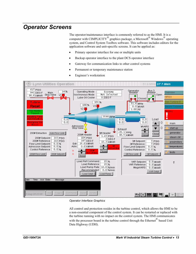
Operator Interface Graphics
All control and protection resides in the turbine control, which allows the HMI to be a non-essential component of the control system. It can be restarted or replaced with the turbine running with no impact on the control system. The HMI communicates with the processor board in the turbine control through the Ethernet based Unit Data Highway (UDH).
GEI-100473A Mark VI Industrial Steam Turbine Control • 13
Steam turbine control screens show a diagram of the turbine with the primary control parameters. The diagram is repeated on most of the screens to enable operators to maintain a visual picture of the turbine’s performance while changing screens. All screens have a menu on the right-hand side of the display, which has a hierarchy of an Overview screen (for a multiple unit site), Unit selection (such as ST1 or ST2), Control/Monitor/Auxiliaries/Tests screen category selection, and a sub-menu of specific screens for each category.
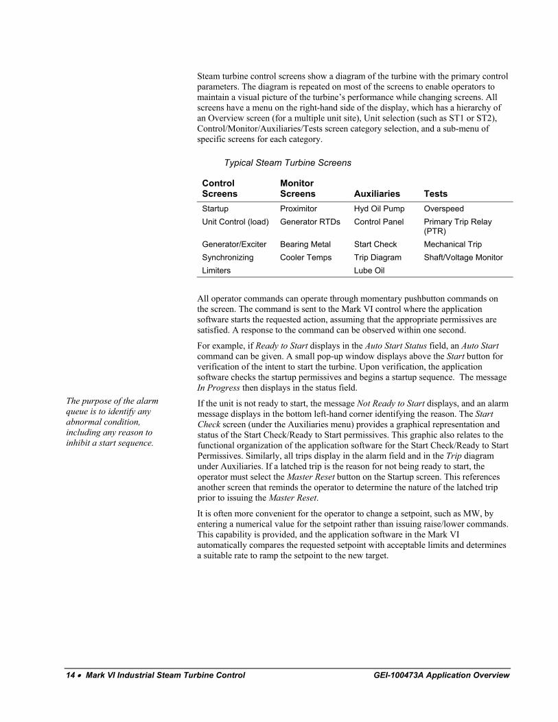
Typical Steam Turbine Screens
Control Screens
Monitor Screens
Auxiliaries
Tests
Startup Proximitor Hyd Oil Pump Overspeed Unit Control (load) Generator RTDs Control Panel Primary Trip Relay
(PTR) Generator/Exciter Bearing Metal Start Check Mechanical Trip Synchronizing Cooler Temps Trip Diagram Shaft/Voltage Monitor Limiters Lube Oil
All operator commands can operate through momentary pushbutton commands on the screen. The command is sent to the Mark VI control where the application software starts the requested action, assuming that the appropriate permissives are satisfied. A response to the command can be observed within one second.
For example, if Ready to Start displays in the Auto Start Status field, an Auto Start command can be given. A small pop-up window displays above the Start button for verification of the intent to start the turbine. Upon verification, the application software checks the startup permissives and begins a startup sequence. The message In Progress then displays in the status field.
The purpose of the alarm queue is to identify any abnormal condition, including any reason to inhibit a start sequence.
If the unit is not ready to start, the message Not Ready to Start displays, and an alarm message displays in the bottom left-hand corner identifying the reason. The Start Check screen (under the Auxiliaries menu) provides a graphical representation and status of the Start Check/Ready to Start permissives. This graphic also relates to the functional organization of the application software for the Start Check/Ready to Start Permissives. Similarly, all trips display in the alarm field and in the Trip diagram under Auxiliaries. If a latched trip is the reason for not being ready to start, the operator must select the Master Reset button on the Startup screen. This references another screen that reminds the operator to determine the nature of the latched trip prior to issuing the Master Reset.
It is often more convenient for the operator to change a setpoint, such as MW, by entering a numerical value for the setpoint rather than issuing raise/lower commands. This capability is provided, and the application software in the Mark VI automatically compares the requested setpoint with acceptable limits and determines a suitable rate to ramp the setpoint to the new target.
14 • Mark VI Industrial Steam Turbine Control GEI-100473A Application Overview
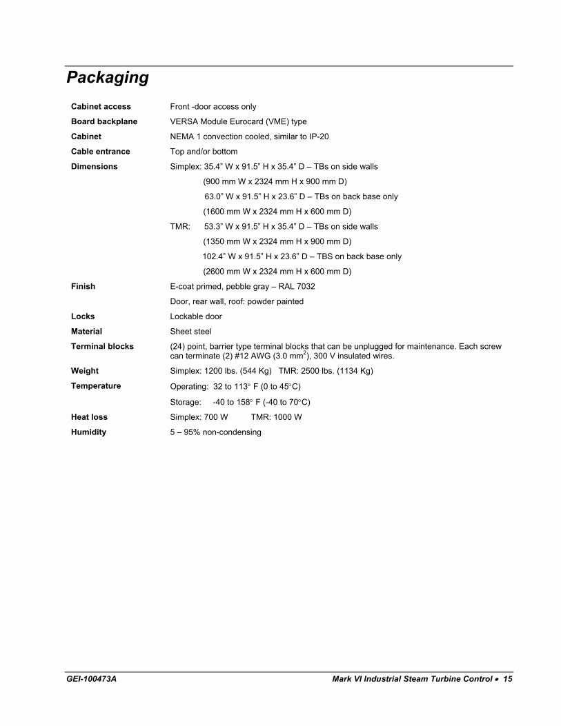
Packaging
Cabinet access Front -door access only
Board backplane VERSA Module Eurocard (VME) type
Cabinet NEMA 1 convection cooled, similar to IP-20
Cable entrance Top and/or bottom
Dimensions Simplex: 35.4” W x 91.5” H x 35.4” D – TBs on side walls
(900 mm W x 2324 mm H x 900 mm D)
63.0” W x 91.5” H x 23.6” D – TBs on back base only
(1600 mm W x 2324 mm H x 600 mm D)
TMR: 53.3” W x 91.5” H x 35.4” D – TBs on side walls
(1350 mm W x 2324 mm H x 900 mm D)
102.4” W x 91.5” H x 23.6” D – TBS on back base only
(2600 mm W x 2324 mm H x 600 mm D)
Finish E-coat primed, pebble gray – RAL 7032
Door, rear wall, roof: powder painted
Locks Lockable door
Material Sheet steel
Terminal blocks (24) point, barrier type terminal blocks that can be unplugged for maintenance. Each screw can terminate (2) #12 AWG (3.0 mm2), 300 V insulated wires.
Weight Simplex: 1200 lbs. (544 Kg) TMR: 2500 lbs. (1134 Kg)
Temperature
Operating: 32 to 113° F (0 to 45°C)
Storage: -40 to 158° F (-40 to 70°C)
Heat loss Simplex: 700 W TMR: 1000 W
Humidity 5 – 95% non-condensing
GEI-100473A Mark VI Industrial Steam Turbine Control • 15
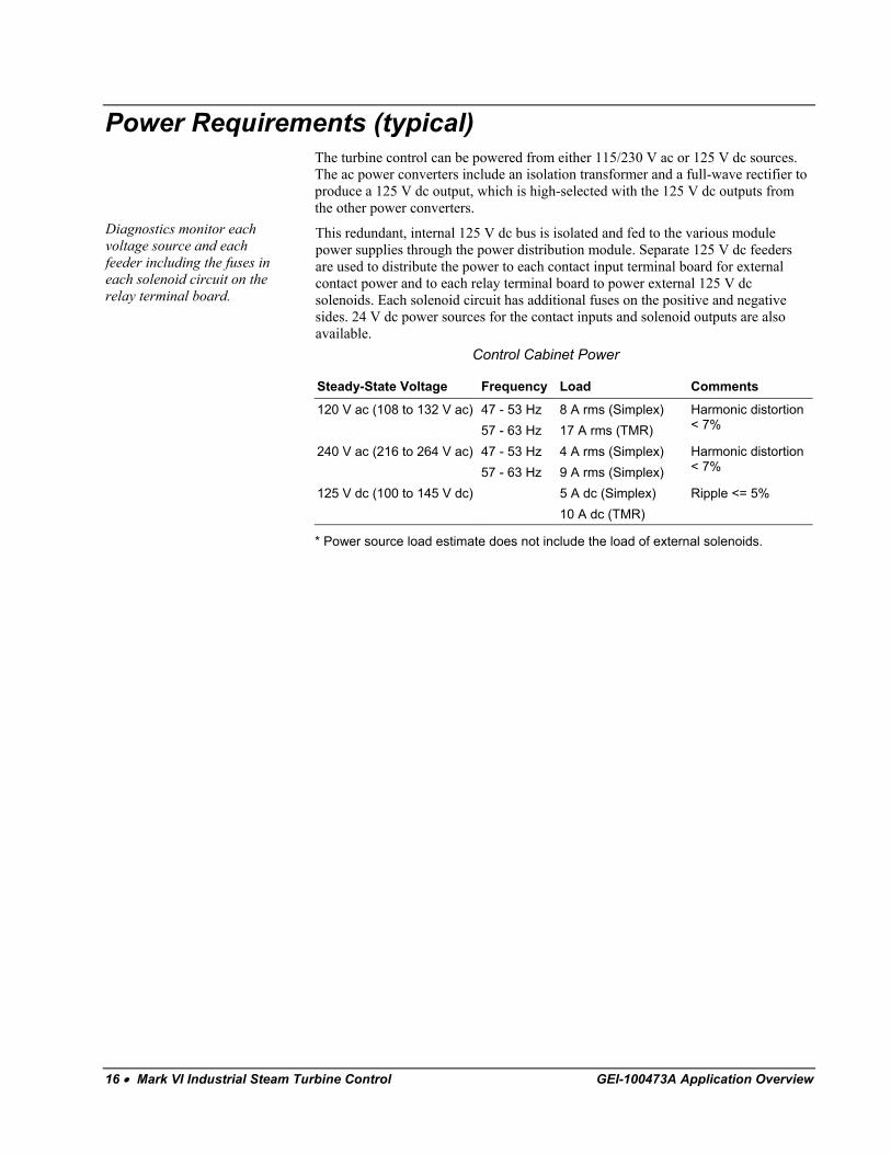
Power Requirements (typical) The turbine control can be powered from either 115/230 V ac or 125 V dc sources. The ac power converters include an isolation transformer and a full-wave rectifier to produce a 125 V dc output, which is high-selected with the 125 V dc outputs from the other power converters.
Diagnostics monitor each voltage source and each feeder including the fuses in each solenoid circuit on the relay terminal board.
This redundant, internal 125 V dc bus is isolated and fed to the various module power supplies through the power distribution module. Separate 125 V dc feeders are used to distribute the power to each contact input terminal board for external contact power and to each relay terminal board to power external 125 V dc solenoids. Each solenoid circuit has additional fuses on the positive and negative sides. 24 V dc power sources for the contact inputs and solenoid outputs are also available. Control Cabinet Power
Steady-State Voltage Frequency Load Comments
120 V ac (108 to 132 V ac) 47 - 53 Hz 57 - 63 Hz
8 A rms (Simplex) 17 A rms (TMR)
Harmonic distortion < 7%
240 V ac (216 to 264 V ac) 47 - 53 Hz 57 - 63 Hz
4 A rms (Simplex) 9 A rms (Simplex)
Harmonic distortion < 7%
125 V dc (100 to 145 V dc) 5 A dc (Simplex) 10 A dc (TMR)
Ripple <= 5%
* Power source load estimate does not include the load of external solenoids.
16 • Mark VI Industrial Steam Turbine Control GEI-100473A Application Overview
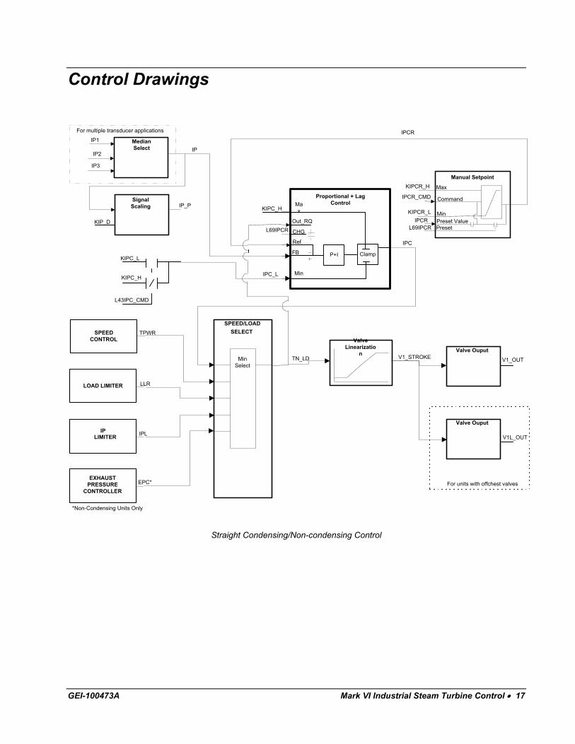
Control Drawings
MedianSelect
SPEED/LOADSELECT
MinSelect
SPEEDCONTROL
TPWR
IPLIPLIMITER
LLRLOAD LIMITER
*Non-Condensing Units Only
EPC*EXHAUST
PRESSURECONTROLLER
SignalScaling
Valve Ouput
Valve Ouput
ValveLinearizatio
n
For units with offchest valves
For multiple transducer applications
IP1
IP2
IP3
IP
IP_P
KIPCR_H
KIPCR_L
IPCR_CMD
IPC
KIPC_H
IPC_L
IPCR
L43IPC_CMD
KIPC_L
KIPC_H
TN_LD V1_STROKE V1_OUT
V1L_OUT
KIP_D
Proportional + LagControl
P+I Clamp
Ref
FB
Max
Min
Out_RQ
CHGL69IPCR
IPCRL69IPCR
Manual Setpoint
Command
Min
Max
Preset ValuePreset
Straight Condensing/Non-condensing Control
GEI-100473A Mark VI Industrial Steam Turbine Control • 17
MedianSelect
SignalScaling
For multiple transducer applications
IP1
IP2
IP3
IP
IP_P
KIPCR_H
KIPCR_L
IPCR_CMD
IPC
KIPC_H
IPCR
KIPC_L
KIP_D
ValveLinearizatio
nValve Ouput
Valve Ouput
V1_STROKE V1_OUT
V1L_OUT
For units with offchest valves
ValveLinearizatio
nValve Ouput
V2_STROKE V2_OUT
HPXPCHP EXTRACTIONCONTROL
*Non-Condensing Units Only
EPC*EXHAUST
PRESSURECONTROLLER
LLRLOAD LIMITER
SPEEDCONTROL
TPWR
IPC_RQ
SINGLEAUTO EXTRACTION
SAX_CMD SAX_STAT
V1_FLO_R
V2_FLO_R
Proportional + LagControl
P+I Clamp
Ref
FB
Max
Min
Out_RQ
CHG
Manual Setpoint
Command
Min
Max
Preset ValuePreset
IPCR
L69IPCR
L69IPCR
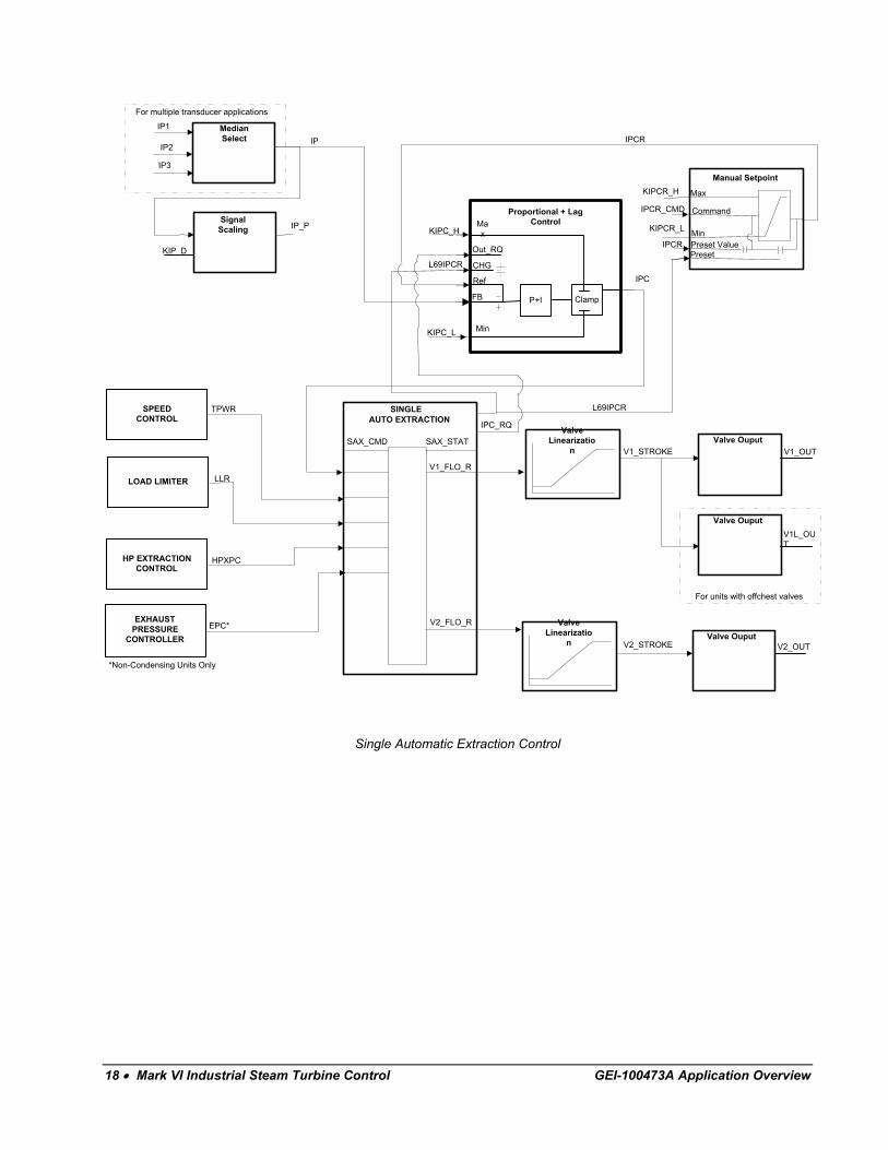
Single Automatic Extraction Control
18 • Mark VI Industrial Steam Turbine Control GEI-100473A Application Overview
MedianSelect
SignalScaling
For multiple transducer applications
IP1
IP2
IP3
IP
IP_P
KIPCR_H
KIPCR_L
IPCR_CMD
IPC
KIPC_H
IPCR
KIPC_L
KIP_D
ValveLinearization Valve Ouput
Valve Ouput
V1_STROKE V1_OUT
V1L_OUT
For units with offchest valves
ValveLinearization Valve Ouput
V2_STROKE V2_OUT
HPXPCHP EXTRACTIONCONTROL
*Non-Condensing Units Only
EPC*EXHAUST
PRESSURECONTROLLER
LLRLOAD LIMITER
SPEEDCONTROL
TPWR
IPC_RQ
Proportional + LagControl
P+I Clamp
Ref
FB
Max
Min
Out_RQ
CHG
Manual Setpoint
Command
Min
Max
Preset ValuePreset
IPCR
L69IPCR
L69IPCR
DOUBLEAUTO EXTRACTION
DAX_CMD DAX_STAT
V1_FLO_R
V3_FLO_R
V2_FLO_RLPXPCLP EXTRACTION
CONTROL
ValveLinearization Valve Ouput
V3_STROKE V3_OUT
Double Automatic Extraction Control
GEI-100473A Mark VI Industrial Steam Turbine Control • 19
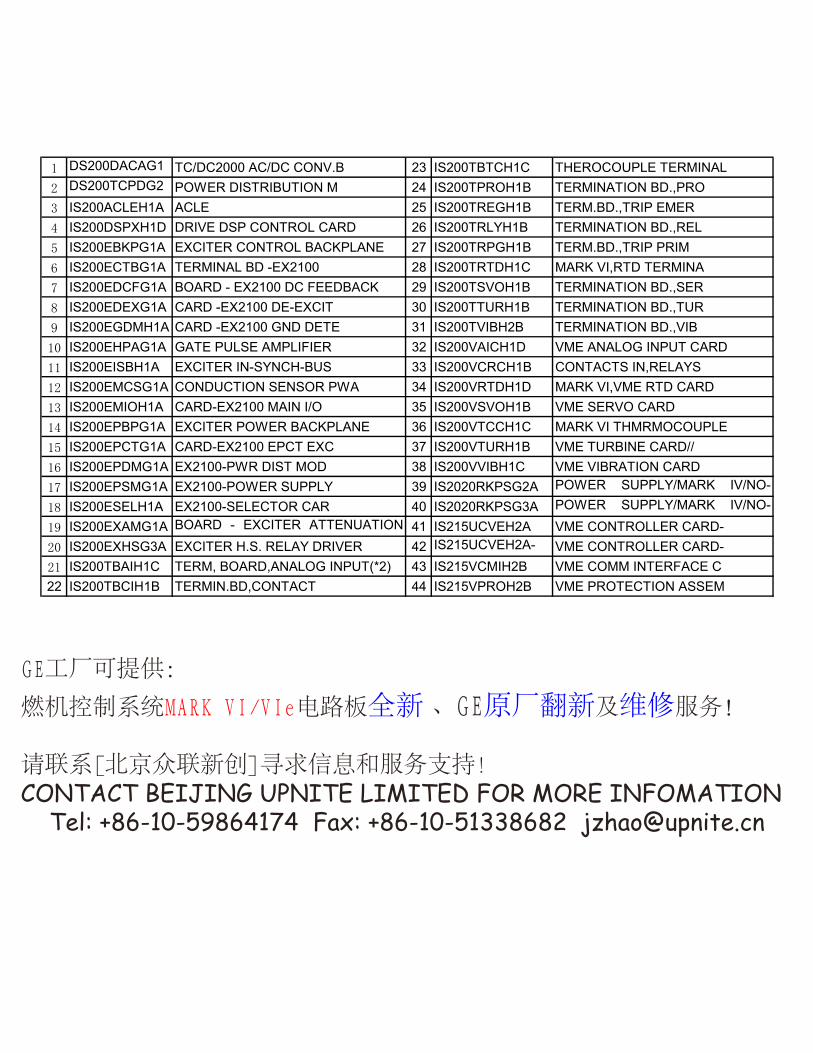
燃机控制系统 电路板全新 、 原厂翻新及维修服务!
CONTACT BEIJING UPNITE LIMITED FOR MORE INFOMATION Tel: +86-10-59864174 Fax: +86-10-51338682 [email protected]
1 DS200DACAG1A
TC/DC2000 AC/DC CONV.B 23 IS200TBTCH1C THEROCOUPLE TERMINAL2 DS200TCPDG2
BPOWER DISTRIBUTION M 24 IS200TPROH1B TERMINATION BD.,PRO
3 IS200ACLEH1A ACLE 25 IS200TREGH1B TERM.BD.,TRIP EMER4 IS200DSPXH1D DRIVE DSP CONTROL CARD 26 IS200TRLYH1B TERMINATION BD.,REL5 IS200EBKPG1A EXCITER CONTROL BACKPLANE 27 IS200TRPGH1B TERM.BD.,TRIP PRIM6 IS200ECTBG1A TERMINAL BD -EX2100 28 IS200TRTDH1C MARK VI,RTD TERMINA7 IS200EDCFG1A BOARD - EX2100 DC FEEDBACK 29 IS200TSVOH1B TERMINATION BD.,SER8 IS200EDEXG1A CARD -EX2100 DE-EXCIT 30 IS200TTURH1B TERMINATION BD.,TUR9 IS200EGDMH1A CARD -EX2100 GND DETE 31 IS200TVIBH2B TERMINATION BD.,VIB10 IS200EHPAG1A GATE PULSE AMPLIFIER 32 IS200VAICH1D VME ANALOG INPUT CARD11 IS200EISBH1A EXCITER IN-SYNCH-BUS 33 IS200VCRCH1B CONTACTS IN,RELAYS12 IS200EMCSG1A CONDUCTION SENSOR PWA 34 IS200VRTDH1D MARK VI,VME RTD CARD13 IS200EMIOH1A CARD-EX2100 MAIN I/O 35 IS200VSVOH1B VME SERVO CARD14 IS200EPBPG1A EXCITER POWER BACKPLANE 36 IS200VTCCH1C MARK VI THMRMOCOUPLE15 IS200EPCTG1A CARD-EX2100 EPCT EXC 37 IS200VTURH1B VME TURBINE CARD//16 IS200EPDMG1A EX2100-PWR DIST MOD 38 IS200VVIBH1C VME VIBRATION CARD17 IS200EPSMG1A EX2100-POWER SUPPLY 39 IS2020RKPSG2A POWER SUPPLY/MARK IV/NO-
335V18 IS200ESELH1A EX2100-SELECTOR CAR 40 IS2020RKPSG3A POWER SUPPLY/MARK IV/NO-335V19 IS200EXAMG1A BOARD - EXCITER ATTENUATION
MO41 IS215UCVEH2A VME CONTROLLER CARD-
20 IS200EXHSG3A EXCITER H.S. RELAY DRIVER 42 IS215UCVEH2A-PK
VME CONTROLLER CARD-21 IS200TBAIH1C TERM, BOARD,ANALOG INPUT(*2) 43 IS215VCMIH2B VME COMM INTERFACE C22 IS200TBCIH1B TERMIN.BD,CONTACT 44 IS215VPROH2B VME PROTECTION ASSEM