Embed Size (px)
Citation preview
DOCUMENT RESOD!
SD 099 499 Cl 002 576
TITLE Module Two: Voltage; Basic Electricity andElectronics Individualized Learning System.
INSTITUTION Bureau of Naval Personnel, Washington, D.C.REPORT NO 'AVMS-94558-2aPUB DATE Jan 72VOTE 166p.; For other modules in the series, see CE 002
S73-589
!DRS PRICE MF-$0.75 8C-$7.80 PLUS POSTAGEDESCRIPTORS Course Content; *Electricity; *Electronics;
Individualized Instruction; Individualized Programs;Industrial Education; Military Training; PostSecondary Education; *Programed Instruction;*Programed Materials; Study Guides; Trade andIndustrial Education; Units of Study (SubjectFields)
ABSTRACTIn this nodule the student will study and learn what
voltage is, how it is generated, what AC (alternating current) and DC(direct current) are and why both kinds are needed, and how tomeasare voltages. The nodule is divided into six lessons: EMT(electromotive force) from chemical action, magnetism,electromagnetic induction, AC voltage, the uses of AC and DC, andmeasuring voltage. Each lesson consists of an overview, a list ofstudy resources, lesson narratives, programed instructionalmaterials, and lesson summaries. (Author/BP)

4.# S DE PART t Mt. tut of t4E At ISEOU(41,0111 ail; ttitiNal lotq..i ItuTE OF
OW At 1016vp t ti r l
.t t viwt
NAVPERS 94558-2a
BASIC ELECTRICITY AND ELECTRONICS
INDIVIDUALIZED LEARNING SYSTEM
MODULE TWO
VOLTAGE
Study Booklet
BUREAU OF NAVAL PERSONNEL
January 1972

OVERVIEW
MODULE TWO
VOLTAGE
In this module /of the Basic Electricity and Electronics Course,
you will study and learn what voltage is, how it Is generated,
what AC and DC voltages are and why both kinds are needed, and
how to measure voltages.
This module is divided Into six lessons to help you learn more
easily. These are:
Lesson I. EMF from Chemical Action
Lesson II. Magnetism
Lesson III. Electromagnetic Induction
Lesson IV. AC Voltage
Lesson V. The Uses of AC and DC
Lesson VI. Measuring Voltage
Don't let any of the above new words bother you; they will be
explained as you come to them in each lesson. If you find the
explanations in the lessons are not clear to you, feel free to
ask questions. Now turn the page and begin Lesson I.

BASIC ELECTRICITY AND ELECTRONICS
INDIVIDUALIZED LEARNING SYSTEM
MODULE TWO
LESSON I
EMF From Chemical Action
Study Booklet
-2,/ 3
Overview Two-I
OVERVIEW
LESSON I
EMF From Chemical Action
In addition to the Module Overview, as you start each lesson, you
will find a lesson overview such as this page. It is merely an outline
of what you will study and learn to do in each lesson. In this lesson
you will study and learn about the following:
- force and current
- EMF
voltage
- sources of EMF
Each of the above topics will be discussed in the order listed. As
you proceed through this lesson, observe and follow directions
carefully.
BEFORE YOU START THIS LESSON. PREVIEW THE LIST OF STUDY RESOURCES
ON THE NEXT PAGE.
4

Study Resources Two-1
LIST OF STUDY RESOURCES
LESSON 1
EMF From Chemical Action
To learn the material in this lesson, you have the option of choosing,
according to your experience and your preferences, any or all of the
following:
STUDY BOOKLET:
Lesson Narrative
Programmed instruction
Lesson Summary
ENRICHMENT MATERIALS:
MAVPERS 93400A-1A "Basic Electricity, Direct Current."
Fundamentals of Electronics. Bureau of Naval Personnel.
Washington, D.C.: U.S. Government Printing Office, 1965.
Remember, you may study any or all of these that you feel are
necessary to answer all Progress Check questions correctly. Do
not forget that in one sense of the word your instructor is a
living resource, perhaps the best. Call him if you have any kind
of a problem.
YOU MAY NOW STUDY ANY OR ALL OF THE RESOURCES LISTED ABOVE. YOU
MAY TAKE THE PROGRESS CHECK AT ANY TIME.
5

Narrative Two-1
NARRATIVELESSON 1
EMF From Chemical Action
Force and Current
As you learned in Module One, increasing the force applied tothe electrons in a wire causes current flow to increase. From
this, you may have concluded that you can change current flowby changing the amount of force applied within the circuit; ifso, you were entirely correct; adding more cells in series ina circuit increases the applied force and causes more current toflow.
Etc
The force which moves electrons through the circuit is calledEMF. EMF is an abbreviation of electromotive force, which meansTirerally the force which moves electrons. Another name you see
and hear frequently is volts e. Voltage, while sometimesabbreviated E, and while a so associated with force, actuallyhas a somewhat different meaning than EMF. The basic unit of
measurement of EMF is force; however, the unit of voltage is
volts.
The values of voltage which you may have to use or measure cover
a large range, and the basic unit is very often combined with the
metric prefixes mid, kilo-, and mega-, so that very
small or very large values can be more easily expressed. You
will rgcall tha; micro- and milli- were discussed 19 Module One
as 10 and 10 '. Ihe prefix kilo- means 1,000 (10') and mega -
mans 1,000,000 (10 ). In other words, 1/1,000 of a volt s
1 millivolt, 1/1,000,000 of a volt is 1 microvolt, and 1,000
volts make 1 kilovolt. You can abbreviate these units the
same way current values are abbreviated. The letter v (upper
or lower case) is used to mean volts; 1,000,000 volts is written
1 Mv. The abbreviation for nypL- is the capital letter M and
kilo- it is k (upper or TOWWFcase). The following table
may help -to clarify these values.
Prefix Abbreviation
NumericalEquivalent
Powerof Ten
micro- v i 10-6
1,000,000
milli- m 1 10-3
kilo- K or k. 1,000 103
mega- M 1,000,000 106
6
Narrative Two-I
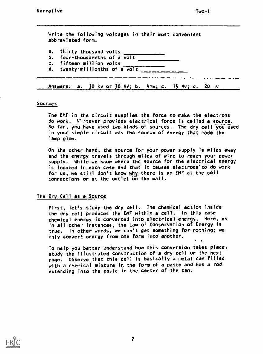
Write the following voltages in their most convenientabbreviated form.
a. Thirty thousand voltsb. four-thousandths of a voltc. fifteen million voltsd. twenty-millionths of a volt
Answers: a. 30 kv or 30 KI/1 b. 4mv; c. 15 my; d. 20 o./
Sources
The EMF in the circuit supplies the force to make the electronsdo work. Vltever provides electrical force is called a source.So far, you have used two kinds of sources. The dry cell you usedin your simple circuit was the source of energy that made thelamp glow.
On the other hand, the source for your power supply is miles awayand the energy travels through miles of wire to reach your powersupply. While we know where the source for the electrical energyis located in each case and that it causes electrons"to do workfor us, we still don't know Will there is an EMF at the cellconnections or at the outlet on the wall.
The Dry Cell as a Source
First, let's study the dry cell. The chemical action insidethe dry cell produces the EMF within a cell. In this case
chemical energy is converted into electrical energy. Here, asin all other Instances, the Law of Conservation of Energy istrue. In other words, we can't get something for nothing; weonly convert energy from one form into another.
To help you better understand how this conversion takes place,study the illustrated construction of a dry cell on the next
page. Observe that this cell is basically a metal can filled
with a chemical mixture in the form of a paste and has a rod
extending into the paste in the center of the can.
7

Narrative
NegativeTerminal
PositiveTerminal
Two- I
Paste
Can
IEST COM.imuitE
Center Rod
One connection of the dry cell (the negative terminal) is attachedto the can or outer case and the other (positive terminal) Is con-
nected to the center rod. The rod and the ease are of differentmaterials. They react with the chemicals in the paste so that
electrons are pulled from the center post and pushed to the outside
case. This action occurs until the charges on the cell's terminals
balance the chemical forces within the paste. When this condition
exists, there is a constant difference of potential or voltage
between the case and cer:ter rod. Observe that within a cell
electrons move from positive to negative - the reverse of what is
true in a circuit.
8

Narrative Two -f
If you connect wires and a lamp to the cell terminals, youprovide a continuous path (circuit) for the electrons to movethrough. The electrons move from the negative case through thecircuit to the positive rod in the dry cell. The chemical actionmoves more electrons from the center post to the case and wehave a continuous current flow.
You know, of course, that a cell will eventually wear out and haveto be replaced just as in a flashlight or a radio. The chemicalseventually change in form, little current flows, and the cell mustbe replaced. There are other kinds of cells that can be rechargedby reversing the movement of electrons through them; this actionrestores the original chemical state. This is done by connectingthe worn-out or discharged cell to another source.
An automobile battery is an example of this kind of cell. (Tech-nically, a battery is a number of cells connected together.) Mostautomobile batteries today are made up of six cells connected inseries, the negative terminal of one connected to the positiveterminal of the next, like this:
Connecting Cells in Series
We will learn several ways that cells can be connected, and howthe kind of connection affects the source voltage. We will alsolearn to recognize these connections symbolized schematically.
Cells connected in series are wired together so that the positiveterminal of one cell is connected to the negative terminal of
another cell. This pictorial illus-tration shows three 1-1/2-volt cells
iaconnected In series, with wires join-ing + to - or - to +. When cells are
1,5Vtrig 451
connected in series, their individualvoltages are additive; thus, we canobtain a greater voltage from the three
cells above than we can from just one. In this case, the outputvoltage will be about 4-1/2 volts.
9

Narrative Two -1
The total voltage supplied by cells in series is equal to the
sum of all the cells' voltages. An example is the kind of cell
used in most auto batteries; each cell has an output of 2 volts.
Several years ago, cars used a 6-volt electrical system, so three
cells were connected in series to get the required voltage. Modern
cars use a 12-volt system, and six cells are Joined In series to
provide the proper voltage for these cars.
When cells are connected in series, they are represented schematic-
ally in this way:
Observe the symbol here shows three cells
with positive terminals connected to
negative terminals, one right after the
other.
Connectil, Cells in Parallel
Cells connected in parallel are wired so that like terminals are
joined - positive to positive, negative to negative.
4.Here is a pictorial illustration
of three cells wired in parallel.
When similar cells are wired in parallel, the output voltage of
all the cells combined is no greater than the voltage of any
single cell. In this case, with three 1-1/2-volt cells connected
in parallel, the output voltage is still 1-1/2 volts. Each of
the cells contributes to the total 1-1/2 volts, and they tend to
. share the woric.)oad. This serves to prolong the life of the cells.
Parallel connection of cells is often used aboard submarines,
where battery power is vital to all ship's operations, and It
is desirable to prolong the life of the batteries.
When three cells are connected in parallel, the schematic repre-
sentation is as shown:
You can see by the symbols that posi-
2---1121/tive terminals are connected together
and negative terminals are connected
1.5,together.
1.5rlow...4 1.
to

Narrative Two-I
Cells Connected in Series ppposition
A third cell connection is called series opposition, or seriesopposing. When cells are connected in this manner, they areconnected in series - one right after another; however, liketerminals are connected together as shown here:
We have seen the utility of cells connected in series, aidingeach other. If we incorrectly connect cells in series withwires going between like terminals (positive to positive, andnegative to negative), as shown in the schematic,
10...1
there is no net voltage across the load, and no current flows.
11

Narrative Two-I
What would the voltage applied to the lamp be
for eacn of these schematics?
Your answers should be:
1. 1.5v (parallel connection)2. Ov (series opposition connection)
3. 4.5v (series connection)
AT THIS POINT, YOU MAY TAKE THE PROGRESS CHECK, OR YOU MAY STUDY ANY
OF THE OTHER RESOURCES LISTED. IF YOU TAKE THE PROGRESS CHECK AND
ANSWER ALL OF THE QUESTIONS CORRECTLY, GO TO THE NEXT LESSON. IF
NOT, STUDY ANY METHOD OF INSTRUCTION YOU WISH UNTIL YOU CAN ANSWER
ALL THE QUESTIONS CORRECTLY.
22
P.I. Two-I
PROGRAMMED INSTRUCTIONLESSON I
Voltage
TEST FRAMES ARE 15, 28 and 37. AS BEFORE, GO FIRST TO TEST FRAME15 AND SEE IF YOU CAN ANSWER ALL THE QUESTIONS THERE. FOLLOW THEDIRECTIONS GIVEN AFTER THE TEST FRAME.
1. Recall that current is caused by the application of an outsideforce. This force is called EMF, and the EMF leads to anassociated voltage.
Current flow is caused by
(EMF)
2. EMF is the force which tends to move electrons. The componentwhich provides this force is called a source. A source is definedas a device which is capable of producing and supplying electricalenergy to some type of electrical apparatus. Such sources aresometimes called voltage sources; however, you should be aware thatvoltage is not the same as EMF.
Which are examples of voltage sources?
,m1.1!
a. ammeterb. dry cellc. lampd. power supply
(b. dry cell; d. power supply)
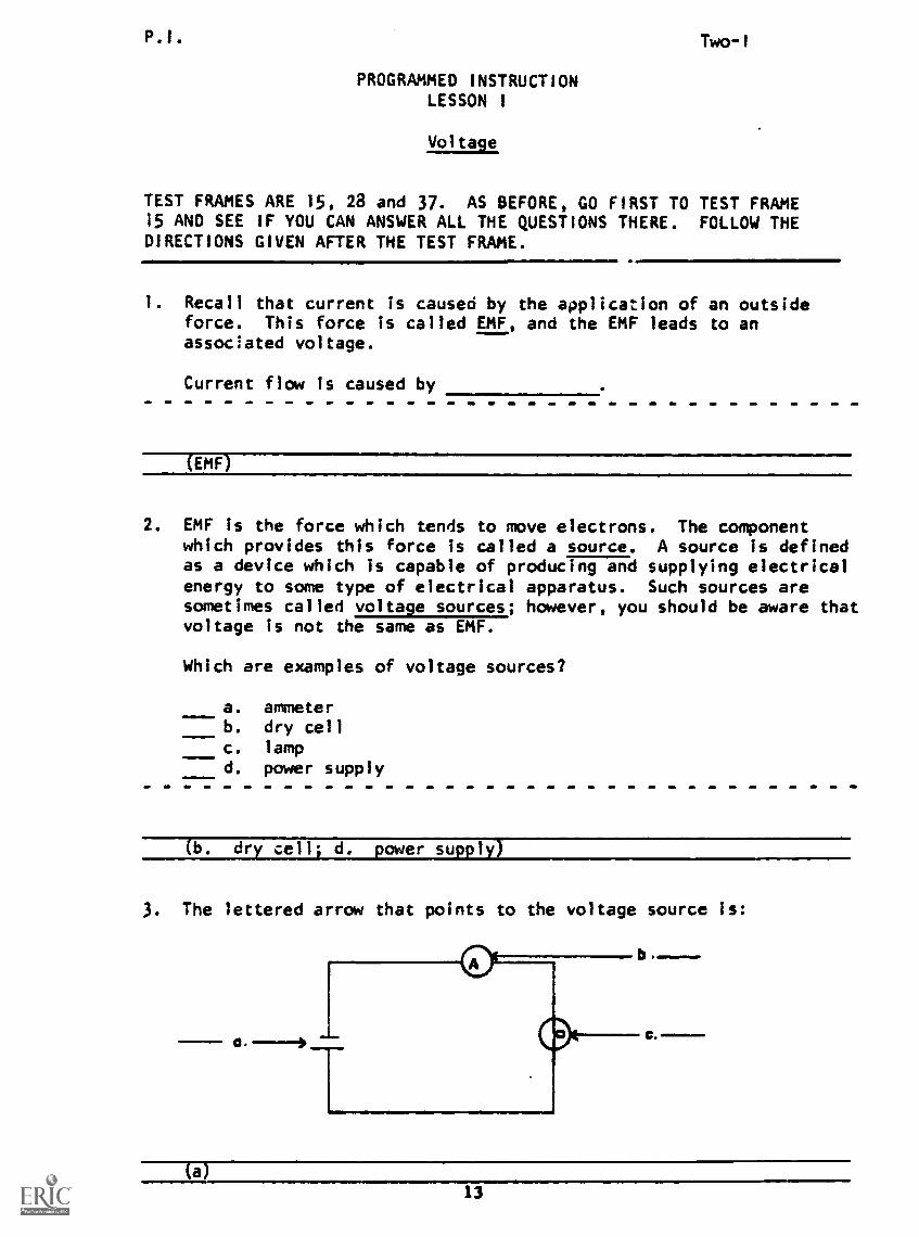
3. The lettered arrow that points to the voltage source is:
(a)13
P.I. Two-1
4. In a dry cell, the materials contained in the cell react chemi-
cally to produce a voltage. In other words, chemical energy is
converted into electrical energy.
Which statement is true?
a. A voltage is generated by the chemical energy released
as a result of mechanical work on the cell.
b. As a result of chemical action, the cell is capable of
delivering electrical energy.
c. The dry cell is a voltage source because it supplies
chemical energy to an external device.
(b) As a result of chemical action, the cell is capable of
delivering electrical energy.
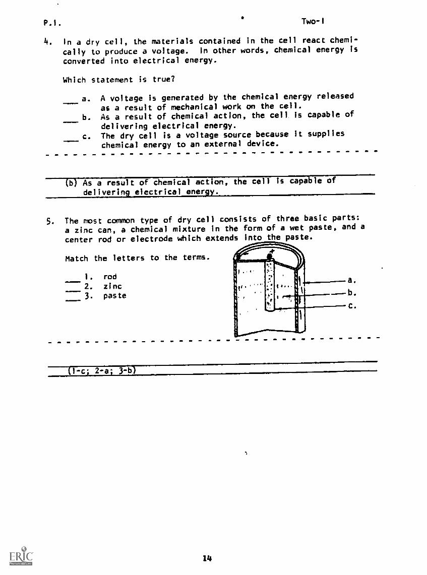
5. The most common type of dry cell consists of three basic parts:
a zinc can, a chemical mixture in the form of a wet paste, and a
center rod or electrode which extends into the paste.
Match the letters to the terms.
1. rod
2. zinc3. paste
a.
b.
C.
(1-c; 2-a; 3-b)
14
P.I. KST COPY AVAILABLE
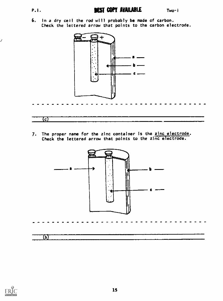
6. In a dry cell the rod will probably be madeCheck the lettered arrow that points to the
b
Two-i
of carbon.carbon electrode.
(c)
7. The proper name for the zinc container is the zinc electrode.Check the lettered arrow that points to the zinc electrode.
(b)
15

P.1. Two-1
8. The chemical mixture or paste packed inside the zinc container(zinc electrode) is called the electrolyte.
Check the lettered arrow which points to the electrolyte.
(a)
9. Match the following:
1. can2. rod
3. wet paste
a. carbon electrodeb. electrolytec. zinc electrode
(I-cL 3-b)
10. Label the basic parts of the cell according to their proper name.
a.
b.
c.
(a. zinc electrode; b. electrolyte; c. carbon electrode)

P.1. MST COPY AVAILABLE Two-1
11. Binding posts or terminals are attached to the electrodes so thatwires may be easily connected to the cell. The carbon electrodeserves as the positive terminal of the cell and the zinc electrodeserves as the negative terminal.
Match the letters to the terms.
1. positive terminal2. negative terminal
12. The chemical reaction of the carbon and zinc electodes with thepaste electrolyte causes an electromoti7e force (EMF) to be pro-duced. This force separates electrons from atoms within thesource and moves the electrons to the negative case. This
causes a positive charge to accumulate on the carbon electrodeand a negative charge on the zinc electrode.
Which illustration shows the result of the chemical reactionbetween the electrodes and the electrolyte?
a. b.
P.1. Two-I
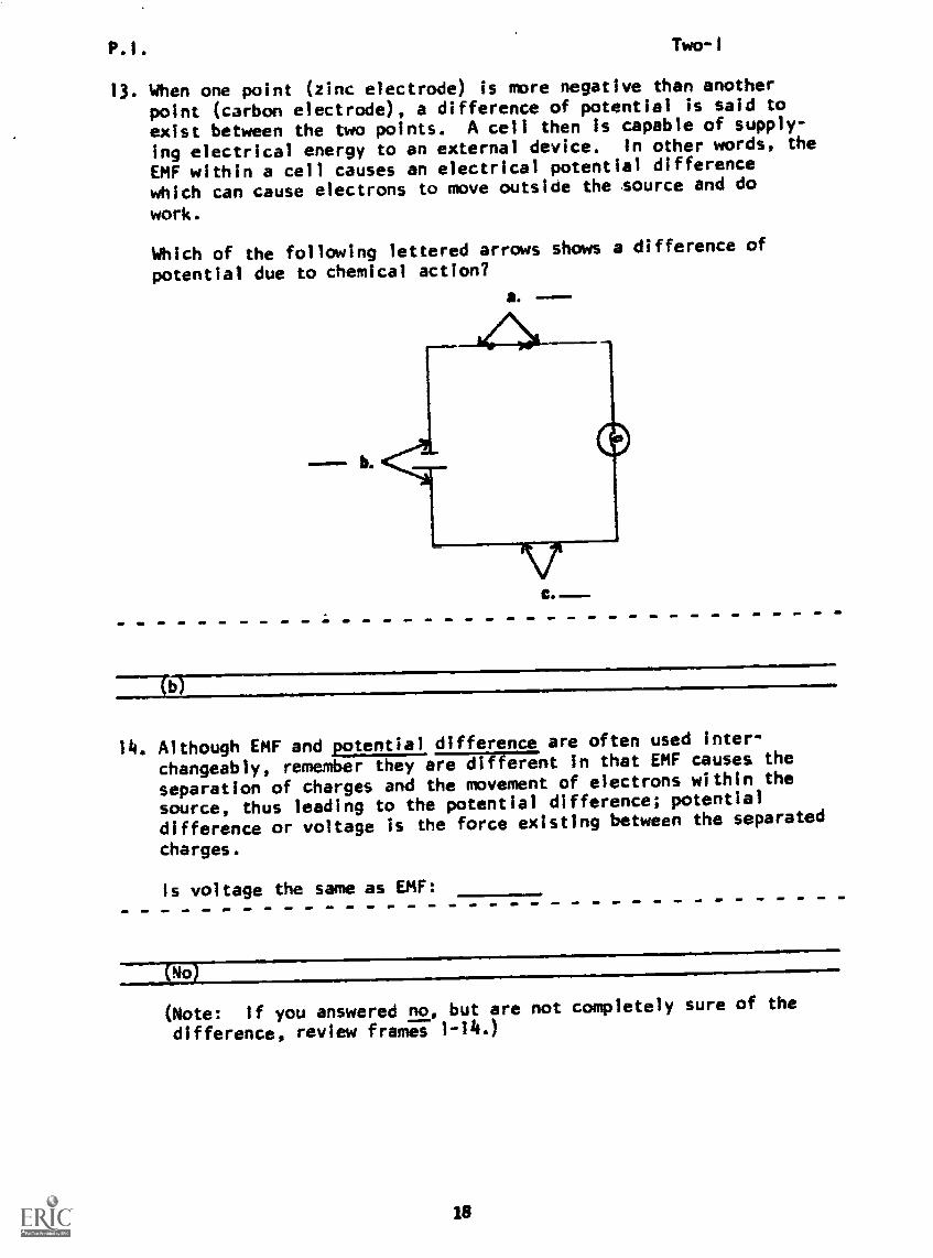
13. When one point (zinc electrode) is more negative than another
point (carbon electrode), a difference of potential is said to
exist between the two points. A cell then is capable of supply-
ing electrical energy to an external device. In other words, the
EMF within a cell causes an electrical potential difference
which can cause electrons to move outside the source and do
work.
Which of the following lettered arrows shows a difference of
potential due to chemical action?
a.
C.
b
14. Although EMF and potential difference are often used inter-
changeably, remember they are in that EMF causes the
separation of charges and the movement of electrons within the
source, thus leading to the potential difference; potential
difference or voltage is the force existing between the separated
charges.
Is voltage the same as EMF:
a(No)
(Note: if you answered no, but are not completely sure of the
difference, review frames 1-14.)
18
P.I.
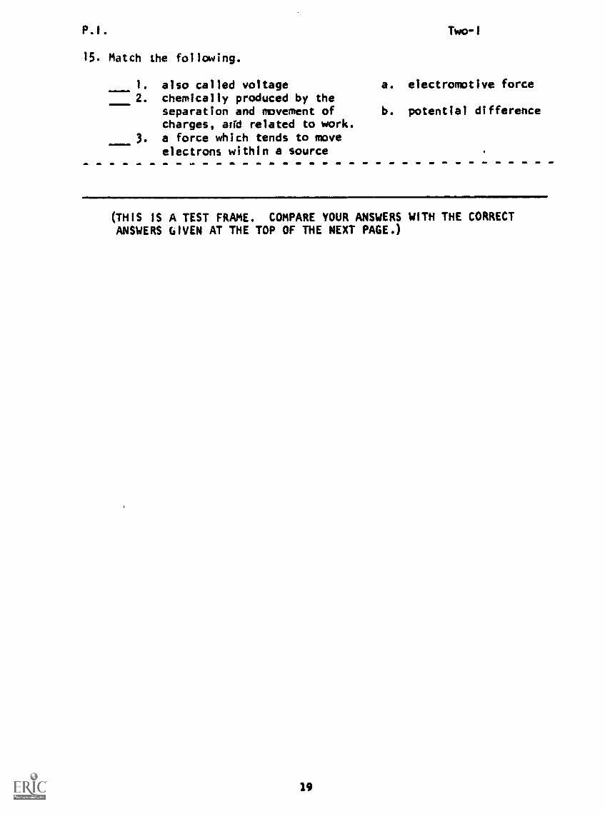
15. Match the following.
1. also called voltage2. chemically produced by the
separation and movement ofcharges, and related to work.
3. a force which tends to moveelectrons within a source
Two-I
a. electromotive force
b. potential difference
(THIS IS A TEST FRAME. COMPARE YOUR ANSWERS WITH THE CORRECTANSWERS GIVEN AT THE TOP OF THE NEXT PAGE.)
19
P.1. Two-1
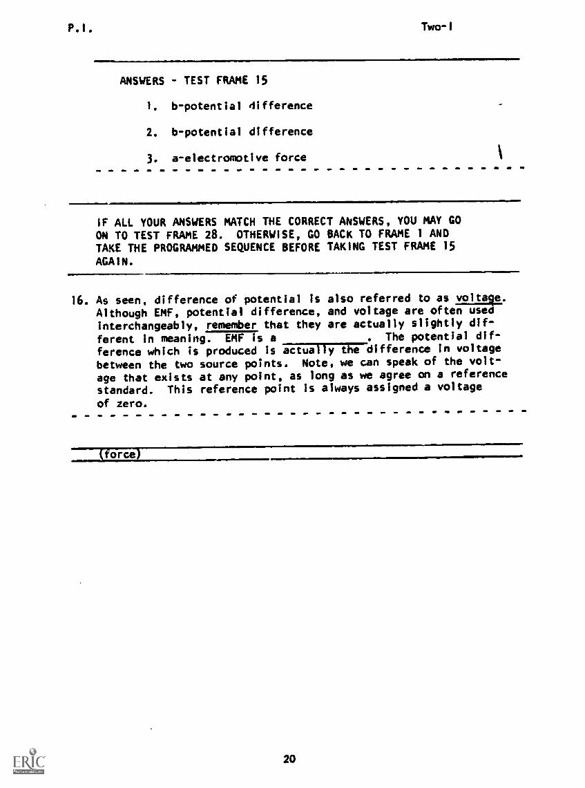
ANSWERS - TEST FRAME 15
1. b-potential difference
2. b-potential difference
3. a-electromotive force
IF ALL YOUR ANSWERS MATCH THE CORRECT ANSWERS, YOU MAY GOON TO TEST FRAME 28. OTHERWISE, GO BACK TO FRAME 1 ANDTAKE THE PROGRAMMED SEQUENCE BEFORE TAKING TEST FRAME 15
AGAIN.
16. As seen, difference of potential is also referred to as voltage.
Although EMF, potential difference, and voltage are often usedinterchangeably, remember that they are actually slightly dif-
ferent In meaning. EMF is a . The potential dif-
ference which is produced is actually the difference In voltage
between the two source points. Note, we can speak of the volt-
age that exists at any point, as long as we agree on a reference
standard. This reference point is always assigned a voltage
of zero.
(force)
20
P.1. IOW MP/ NAURU Two -1
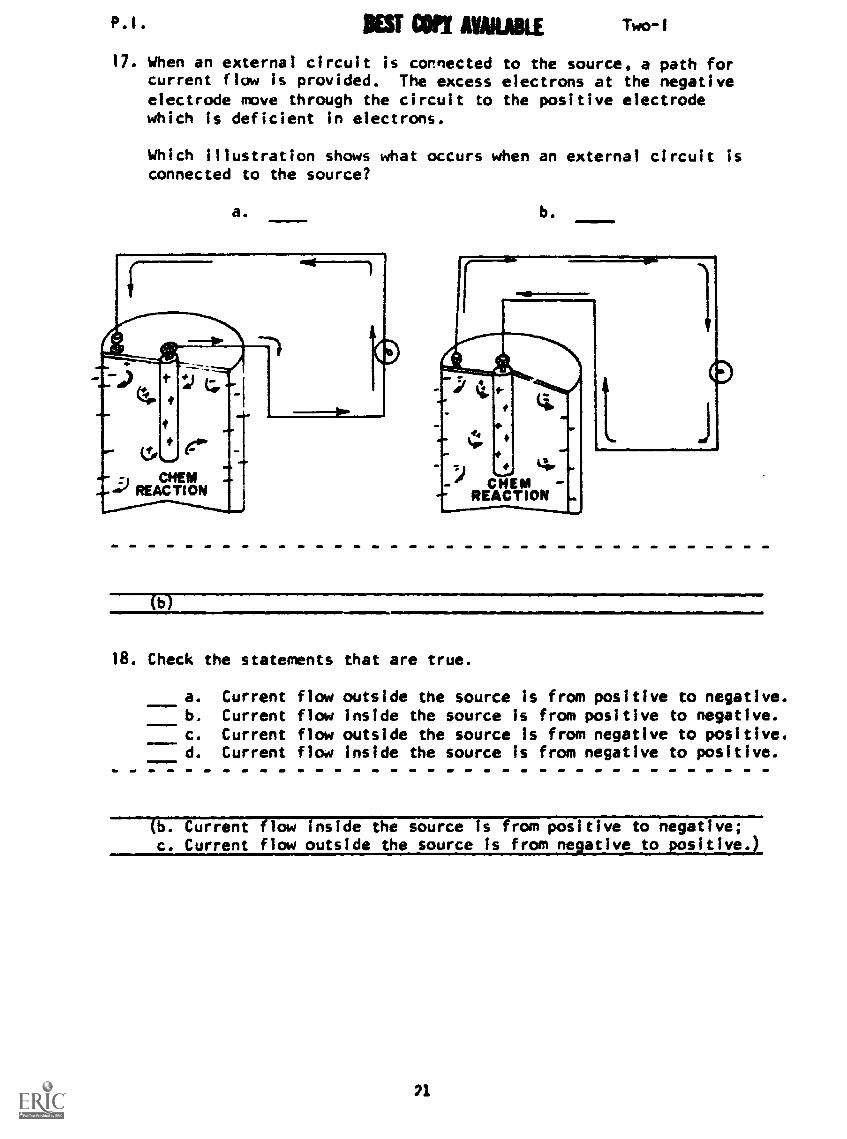
17. When an external circuit is connected to the source, a path forcurrent flow is provided. The excess electrons at the negativeelectrode move through the circuit to the positive electrodewhich is deficient in electrons.
Which Illustration shows what occurs when an external circuit isconnected to the source?
a.11111.=1..1 b.
(b)
18. Check the statements that are true.
a. Current flow outside the source is from positive to negative.b. Current flow inside the source Is from positive to negative.c. Current flow outside the source is from negative to positive.d. Current flow inside the source is from negative to positive.
(b. Current flow inside the source is from positive to negative;c. Current flow outside the source is from negative to positive.)
21

P.I. Two-1
19. The major drawback of a dry cell is that it eventually loses itsability to produce a potential difference. This occurs becauseof chemical changes within the cell; remaining chemical energyis no longer converted into electrical energy.
Which is true?
400=11.
a. A dry cell can produce voltage indefinitely and doesnot have to be replaced.
b. A dry cell can produce voltage only as long as thechemical reaction within the cell continues.
(b) A dry cell can produce voltage only as long as the chemicalreaction within the cell continues.
NOTE: There are other kinds of cells such as lead-acid cells,which can be recharged by reversing the movement of electronsthrough them, rebuilding materials in the cell. This is done
by connecting the cell to another source. An automobile bat-
tery Is an example of this kind of cell.
20. Since dry cells have a limited voltage output, there must besome method of obtaining more voltage than that available from
one cell - by connecting the negative terminal of one cell
to the positive terminal of another cell until the desired
voltage is obtained. This type of cell connection is called
series aiding.
Which diagram shows a series aiding connection?
a.
b.
CE)
(b)
22
P.I. Two-1
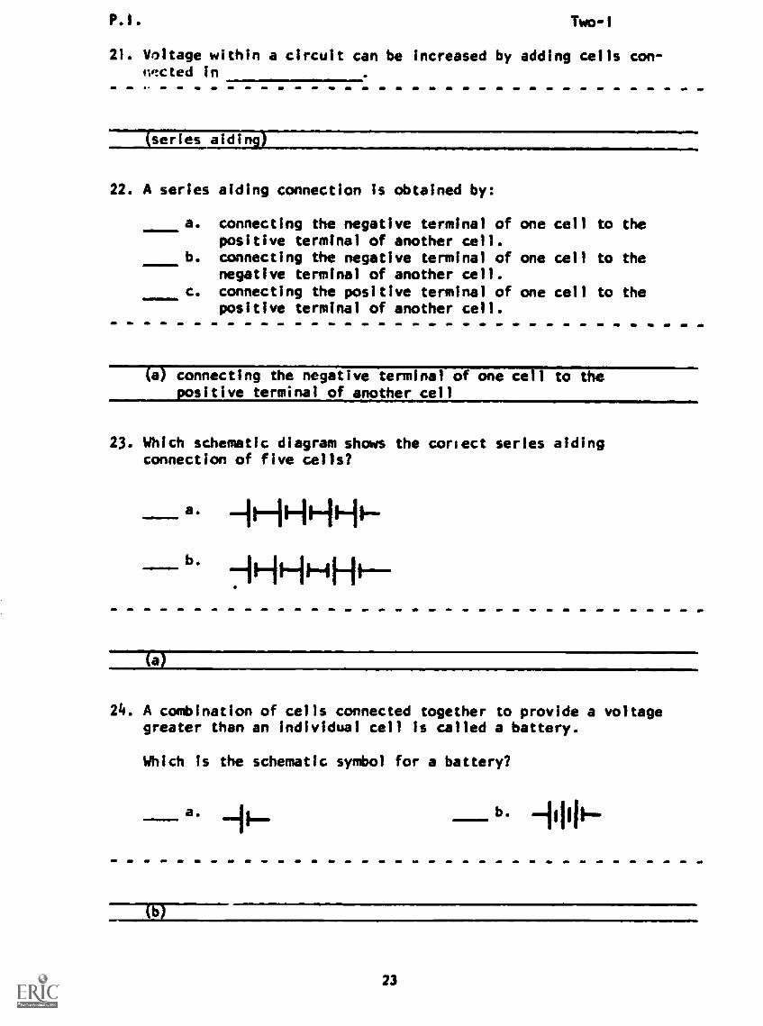
21. Voltage within a circuit can be increased by adding cells con-nncted in
(series aiding)
22. A series aiding connection is obtained by:
a. connecting the negative terminal of one cell to thepositive terminal of another cell.
b. connecting the negative terminal of one cell to thenegative terminal of another cell.
c. connecting the positive terminal of one cell to thepositive terminal of another cell.
(a) connecting the negative terminal of one cell to thepositive terminal of another cell
23. Which schematic diagram shows the correct series aidingconnection of five cells?
a. -11-14-11-11-
711-11÷Fit
(a)
24. A combination of cells connected together to provide a voltagegreater than an individual cell is called a battery.
Which is the schematic symbol for a battery?
a. b.
(b)
23
R.I. Two-1
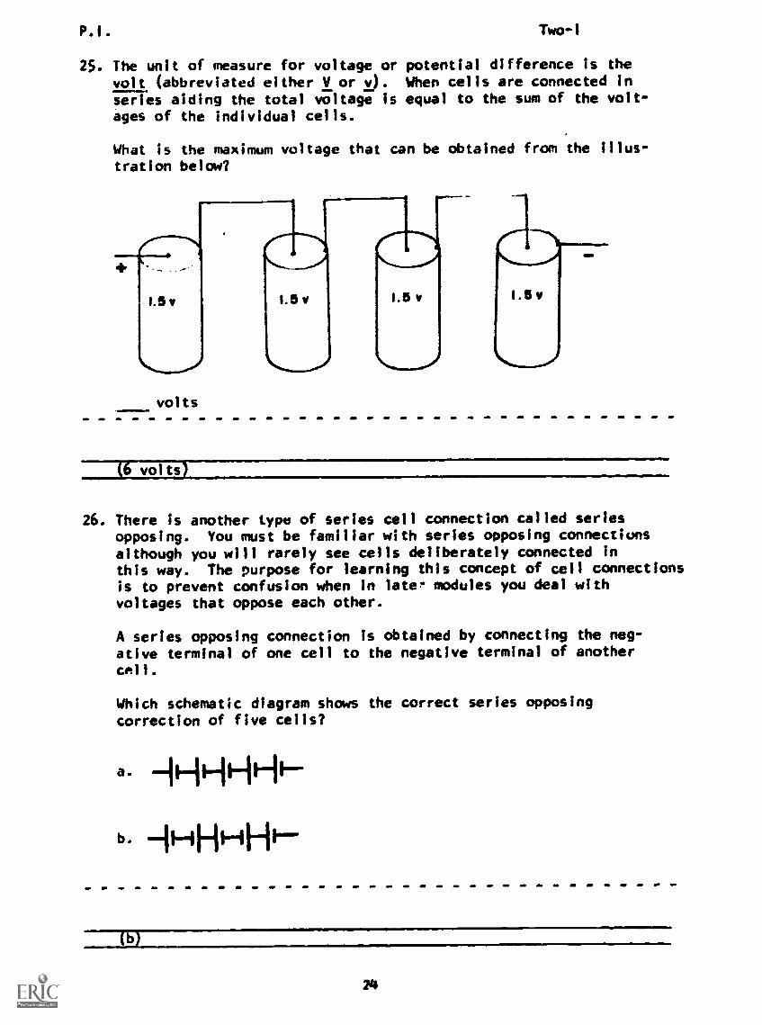
25. The unit of measure for voltage or potential difference is thevolt (abbreviated either V or v). When cells are connected inseries aiding the total voltage is equal to the sum of the volt-ages of the individual cells.
What is the maximum voltage that can be obtained from the illus-tration below?
i.5,
volts
i.5v 1.5 v
volts
26. There is another type of series cell connection called seriesopposing. You must be familiar with series opposing connectionsalthough you will rarely see cells deliberately connected inthis way. The purpose for learning this concept of cell connectionsis to prevent confusion when in later modules you deal withvoltages that oppose each other.
A series opposing connection is obtained by connecting the neg-ative terminal of one cell to the negative terminal of anothercall .
Which schematic diagram shows the correct series opposingcorrection of five cells?
a. +11--11Hi
b. 1/-4FP-1-11-1/
24

P.1. Two-I
27. When a cell is connected series opposing, its voltage issubtracted from the sum of all voltages connected series aidingto obtain the total voltage available from the combination.
Example:
You will note that two of the cells are connected series aidingand one is connected opposing the two; therefore, the two inseries aiding provide 3 v opposing the 1.5 v of the one cell.Total voltage is 3 v - 1.5 v or 1.5 v.
What is the total voltage of the illustration below?
volts
Tzero volts)
25
P.1. Two-I
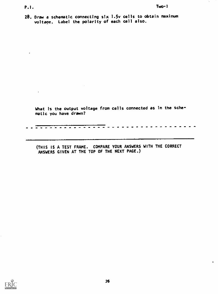
28. Draw a schematic connecting six 1.5v cells to obtain maximum
voltage. Label the polarity of each cell also.
What is the output voltage from cells connected as in the sche-
matic you have drawn?
(THIS IS A TEST FRAME. COMPARE YOUR ANSWERS WITH THE CORRECTANSWERS GIVEN AT THE TOP OF THE NEXT PAGE.)
26
P.I. Two-I
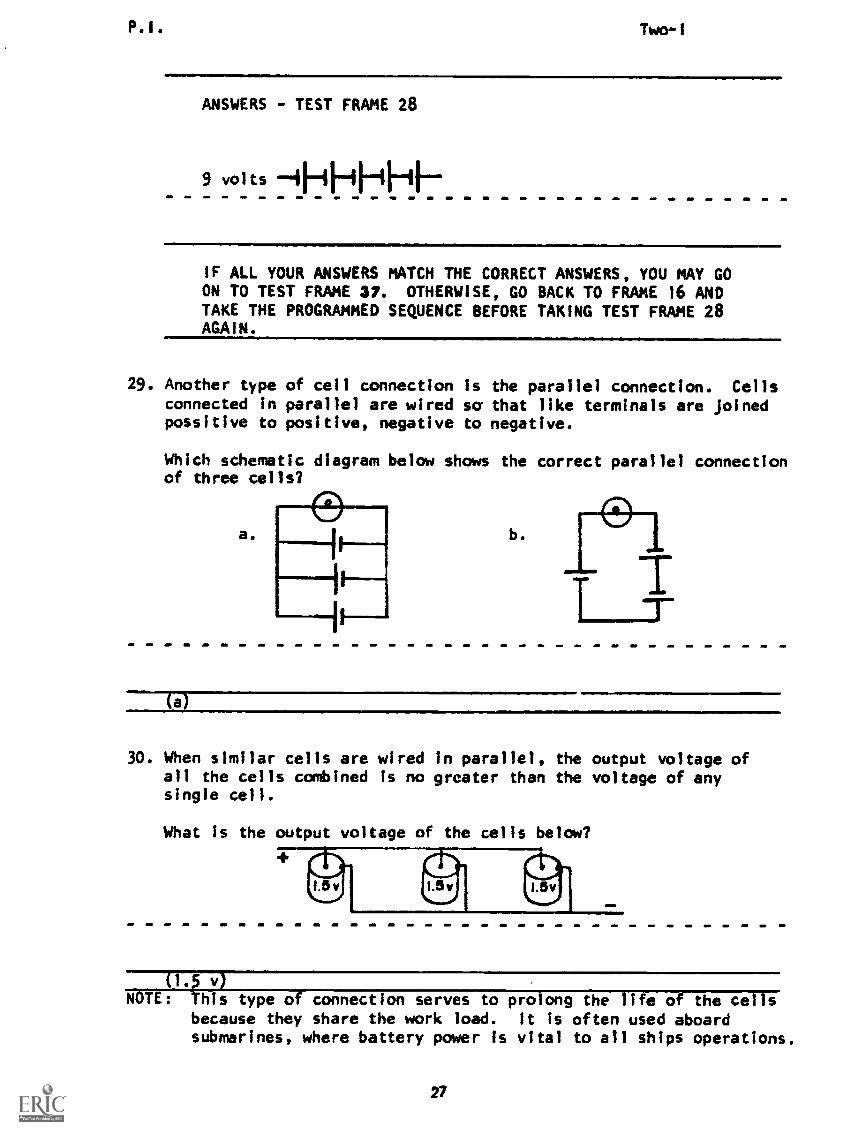
ANSWERS - TEST FRAME 28
9 volts 11iF+11-11--
IF ALL YOUR ANSWERS MATCH THE CORRECT ANSWERS, YOU MAY GOON TO TEST FRAME 37. OTHERWISE, GO BACK TO FRAME 16 ANDTAKE THE PROGRAMMED SEQUENCE BEFORE TAKING TEST FRAME 28AGAIN.
29. Another type of cell connection is the parallel connection. Cellsconnected in parallel are wired sa that like terminals are joinedpossitive to positive, negative to negative.
Which schematic diagram below shows the correct parallel connectionof three cells?
a. b.
30. When similar cells are wired in parallel, the output voltage ofall the cells combined is no greater than the voltage of anysingle cell.
What is the output voltage of the cells below?
1.5v 1.5v
(1.5 v)NOTE: This type of connection serves to prolong the life of the cells
because they share the work load. It is often used aboardsubmarines, where battery power is vital to all ships operations.
27
P.I. Two-I
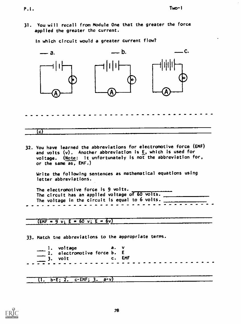
31. You will recall from Module One that the greater the force
applied the greater the current.
In which circuit would a greater current flow?
b. C.
32. You have learned the abbreviations for electromotive force (EMF)
and volts (v). Another abbreviation is E, which is used for
voltage. (Note: It unfortunately is not the abbreviation for,
or the same as, EMF.)
Write the following sentences as mathematical equations using
letter abbreviations.
The electromotive force is 9 volts.The circuit has an applied voltage of 60 volts.The voltage in the circuit is equal to 6 volts.
(EMF E ga 60 v; E 6v)
33. Match tne abbreviations to the appropriate terms.
1. voltage a. v
2. electromotive force b. E
3. volt c. EMF
(1. b-E; 2. c-EMF; 3. a -vJ
28

P.E. Two-1
34. Large values of voltage may be expressed as kilovolts. Onekilovolt represents 1000 volts and is symbolized by the lettersKV or kv.
50 kv represents3000 v represents4.5 kv represents
v.
kv.
v.
(50,000 v; 3 kv; 4,500 v)
35. Small values of voltage may be expressed as millivolts or micro-volts.
One millivolt represents 1/1000 of 1 volt or 1 x 10⁻³ volts andis symbolized by the letters mv.
One microvolt represents 1/1,000,000 of 1 volt or 1 x 10⁻⁶
voltsand is symbolized by the letters uv.
o.0025 v represents0.0015 v represents0.000005 v represents
ITIV;
my;my;
uvuvuv
(2.5 mv) 2500 pv - 1.5 my; 1500 uv - 0.005 my; 5 pv)
36. Match the following.
1. 25 kv a. 25 volts2. 5 pv b. 0.025 volts3.
4.
0.005 v25 mu
c.
d.
25 kilovolts5 millivolts
5. 25 v e. 5 microvolts6. 0.005 my
7. 25,000 vA!!
(1-c; 3-d; 4-b; 5-a; 6-e; 7-c)
29

P.I. Two-I
37. Match the term to its correct definition or description.
1. when one point is more negativethan another point
2. also called voltage
3. force which moves electronsinside the source
4. unit of measure for voltage
5. capable of producing andsupplying electrical energyto some type of electricalapparatus
6. two or more cells joinedfrom the negative terminalof one to the positiveterminal of another
a. voltage source
b. potential difference
c. series connection
d. volt
e. EMF
(THIS IS A TEST FRAME. COMPARE YOUR ANSWERS WITH THE CORRECT
ANSWERS GIVEN ON THE TOP OF THE NEXT PAGE.)
30

P.I. Two-I
ANSWERS - TEST FRAME 37
1. b - potential difference
2. b - potential difference
3. e EMF
4. d - volt
5. a - voltage source
6. c - series connection
IF ANY OF YOUR ANSWERS ARE INCORRECT, GO BACK TO FRAME 29AND TAKE THE PROGRAMMED SEQUENCE.
IF YOUR ANSWERS ARE CORRECT, YOU MAY TAKE THE PROGRESS CHECK,OR YOU MAY STUDY ANY OF THE OTHER RESOURCES LISTED. IF YOUTAKE THE PROGRESS CHECK AND ANSWER ALL THE QUESTIONS COR-RECTLY, GO ON TO THE NEXT LESSON. IF NOT, STUDY ANY METHODOF INSTRUCTION YOU WISH UNTIL YOU CAN ANSWER ALL THE QUES-TIONS CORRECTLY.
31
Summary
SUMMARYLESSON I
Two-I
EMF From Chemical Action
As you learned in Module One, a force applied to the electrons in a
wire causes current to flow. The subject of this lesson Is the forceinside the cell which tends to move the electrons to one of the cell's
terminals. Electromotive Force, abbreviated EMF, is the technically
correct name for this force. Voltage, while sometimes abbreviated Eand also associated with force, actually has a somewhat different
meaning than EMF.
The basic unit of measurement of EMF is actually force; however, the
unit of voltage is that of work per unit charge or simply volts. Because
the values of voltage you may use range from very small fractions of
a volt to very large numbers of volts, the basic unit is often used
with metric prefixes. The most often used prefixes are micro- andwhich were covered in Module One, and kilo- (thousand and
mew_ (million). The letter V (either upper or lower case) stands
for volt, and K (either upper or lower case) means kilo-, so one
thousand volts may be written 1 kv. The capital letterM is used for
mega-, so 1 MV would be read one megavolt. (Don't confuse this with
the Roman number M, meaning one thousand.)
The part of an electric circuit which supplies the EMF is called a
source. In the simple circuit of Module One, the source was a dry
cell; in your power supply, the source is the generator at the power
plant. The dry cell uses chemical action to develop its EMF; the
generator converts mechanical action to produce an EMF. Since this
lesson is concerned with chemically produced EMF, we will proceed to
study the dry cell.
Within a dry cell, the energy produced by the chemical reaction between
a paste (electrolyte) and the zinc shell of the cell separates electrons
from their atoms and tends to move them to one of the cell terminals.
This action results in a force between these electrons at the nega-
tive terminal and the positive charges left at the other terminal. The
force of the chemical action leads to a difference of potential or volt-
age between the terminals. When no outside wire connects the terminals
of the cell, this difference of potential is a constant value associated
with the particular cell.
If a circuit like the one built in Module One is connected to the ter-
minals of the cell, the force (EMF) between the charges on the cell's
terminals, as described by Coulomb's Law, will move electrons through
the circuit. The continuing chemical action will move more electrons
to the negative terminal as fast as they move off into the circuit. In
this way a continuous steady current flows.
You know, of course, that the chemicals will eventually change in form,
little current will flow, and the dry cell will have to be replaced.
32
Sunnis ry Two-I
Another kind of cell can be recharged by applying to the cell an outsidecurrent flowing in the opposite direction. This reversed current re-verses the chemical action. Batteries made of cells which can be re-charged are called storage batteries. This kind of battery is used inan automobile. (Note: a battery is just a number of cells connectedtogether.)
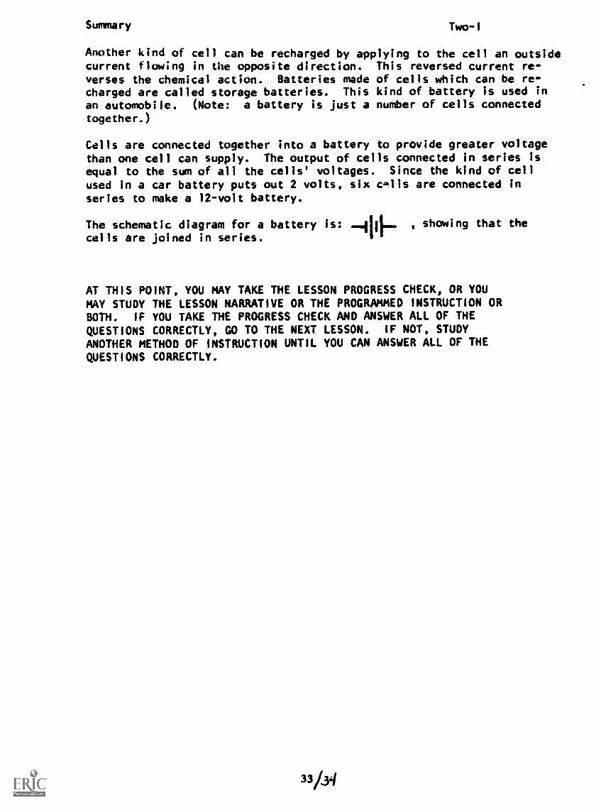
Cells are connected together into a battery to provide greater voltagethan one cell can supply. The output of cells connected in series isequal to the sum of all the cells' voltages. Since the kind of cellused in a car battery puts out 2 volts, six Gills are connected inseries to make a 12-volt battery.
The schematic diagram for a battery is: 1IF- , showing that the
cells are joined in series.
AT THIS POINT, YOU MAY TAKE THE LESSON PROGRESS CHECK, OR YOUMAY STUDY THE LESSON NARRATIVE OR THE PROGRAMMED INSTRUCTION ORBOTH. IF YOU TAKE THE PROGRESS CHECK AND ANSWER ALL OF THEQUESTIONS CORRECTLY, GO TO THE NEXT LESSON. IF NOT, STUDYANOTHER METHOD OF INSTRUCTION UNTIL YOU CAN ANSWER ALL OF THEQUESTIONS CORRECTLY.
33/34

BASIC ELECTRICITY AND ELECTRONICS
INDIVIDUALIZED LEARNING SYSTEM
MODULE TWOLESSON II
Ma9netIsm
Study Booklet
35
Overview Two-II
OVERVIEW
LESSON II
Magnetism
In this lesson you will study and learn about the following:
- magnetic fields
-rules governing lines of force
- magnetic attraction
- flux density
Each of the above topics will be discussed in the order listed.
As you proceed through this lesson, observe and follow directions
carefully.
BEFORE YOU START THIS LESSON, PREVIEW THE LIST OF STUDY RESOURCES
ON THE NEXT PAGE.
36
Study Resources Two-II
LIST OF STUDY RESOURCES
LESSON II
Magnetism
To learn the material in this lesson, you have the option of choosing,
according to your experience and your preferences, any or all of the
following:
STUDY BOOKLET:
Lesson Narrative
Programmed Instruction
Lesson Summary
ENRICHMENT MATERIAL:
NAVPERS 93400A-IA "Basic Electricity, Direct Current."
Fundamentals of Electronics. Bureau of Naval Personnel.
Washington, D.C.: U.S. Government Printing Office, 1965.
You may study whatever learning materials you feel are necessary to
answer the questions in the Lesson Progress Check. All your answers
must be correct before you can go to Lesson III. Remember, your in-
structor Is available at all times for any assistance you may need.
YOU MAY NOW STUDY ANY OR ALL OF THE RESOURCES LISTED ABOVE. YOU
MAY TAKE THE PROGRESS CHECK AT ANY TIME.
37
Narrative Two-II
NARRATIVELESSON II
Magnetism
Why Study Magnetism
Let us now consider in greater detail the source of the voltageavailable at a wall electrical outlet. This putential differenceis delivered from a power plant through many miles of wires toyour work table. At the power plant, huge generators convertmechanical energy into electrical energy through magnetism.11711;a0that a cell converts chemical energy into electricalenergy.)
Generators supply all the electrical needs on board ships also.The caring for these generators and the switching systems thatroute their output to all parts of a ship is the Job of the EM;however, personnel of all ratings trained in this course dependupon and work with the electricity generated. To understand whathappens inside a generator you need to know something about mag-netism because this is one of the basic factors involved inthe conversion of mechanical energy into electricity.
No one knows the full details as to what causes magnetism, butwe can see how it works and what it does. You have probably seenmagnets and know that they can pull some things to them. If
you've played with two magnets, you know that they sometimesattract and sometimes repel each other.
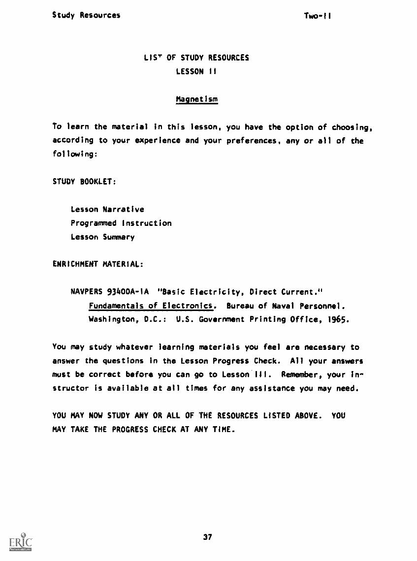
Magnetic Field
To explain the things a magnet does, scientists use a conceptcalled lines of flux or lines of force. These are imaginary lines;
you cannot see them. They represent magnetic force. The linesof flux around a magnet make up a pattern called a ma neticThe effects of this force pattern can be shown by p al c ng aof glass on a magnet lying on a flat surface. Iron filingssprinkled on the glass will settle in a pattern of lines Just likethe flux lines. Here is a drawing of the flux pattern (magneticfield) around a bar magnet:
/iIf4
...
.....1....
..-
f
i46%
....
....I....
.
''
.... -..-
....,
..."
''
...
/
1.:".
....__
-
I
1
1
/i
s.
' -
1
.
3$

Narrative arr AMIABLE Two-11
The magnetic field around a horeshoe magnet, as indicated by theiron filings, looks like this:
-a
et1; t .0.14417.
t
Rules Governing Lines of Force
Lines of flux were devised as a way to explain magnetism.Scientists have discovered certain rules that seem to explain linesof flux.
1. Magnetic lines of force alwayseach loop is always within theagain at the pattern for a bar
form complete loops. Part ofmaterial of the magnet. Lookmagnet:
2. Magnetic lines of force have polarity. This means they have adirection. The ends of the bar magnet are designated N(or North) and S (or South). By definition the lines offlux travel through a magnet internally, from the SouthPole to the North Pole; and externally always leave the (N)
39
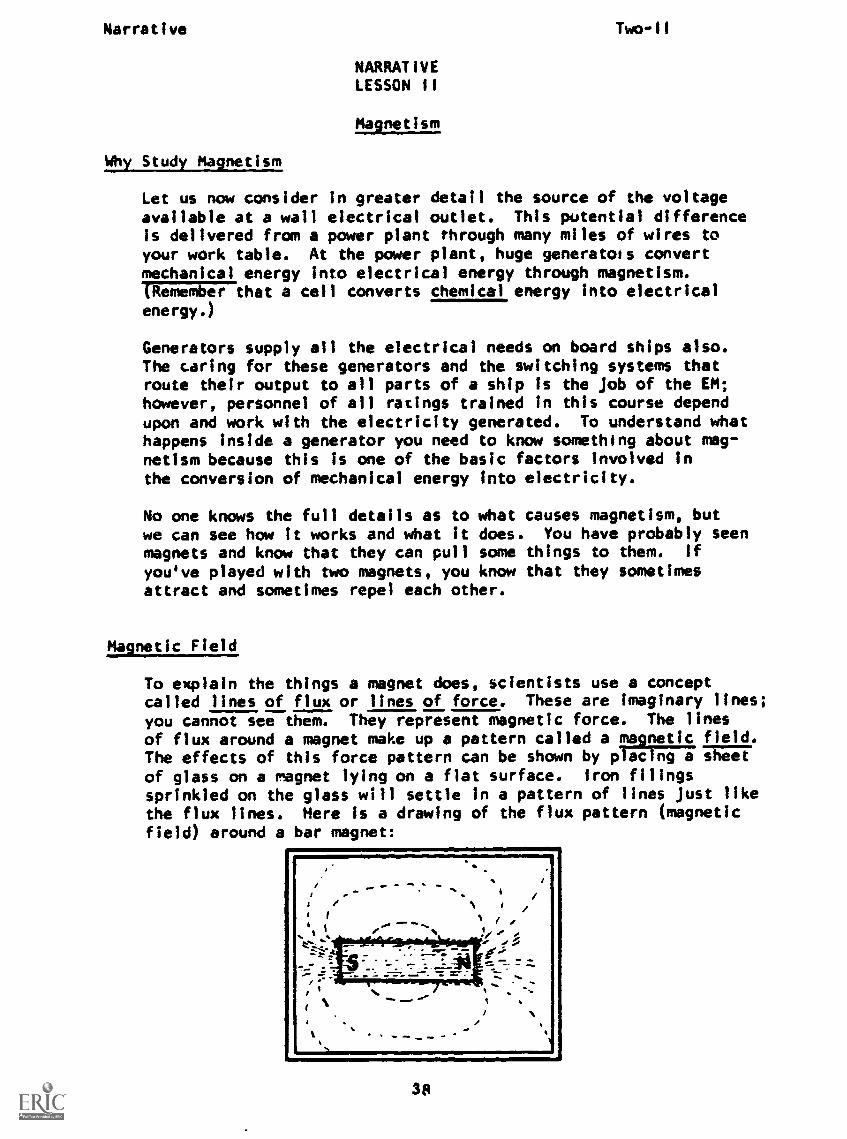
Narrative Two-II
Pole and enter the (S) Pole even though they do not actuallyflow like a stream. We can add arrowheads to the magneticfield of a bar magnet to represent this.
3. Magnetic lines of force repel each other. This, togetherwith Rule 1, that they always form closed loops, means thatlines of force will never cross.
4. Magnetic lines of force always try to form the smallest possible
loop. All the lines of force around a magnet would contractright down to the surface of the magnet if they did nottend to repel each other. The balance of the two forces (con-traction and repulsion) result in the patterns previously
shown.
5. Magnetic lines of force pass through any kind of material.There is no known substance that lines of force cannot enter.There are some materials that they will enter into or follow
much more readily than others, but there are none which willblock their passage.
6. Magnetic lines of force always enter or leave a magnet per -pendic- sr to its surface. In the case of the bar magnet,
most of the lines of force enter and leave the magnet atright angles to its ends, but some still leave at night an-gles to each side.
Magnetic Attraction
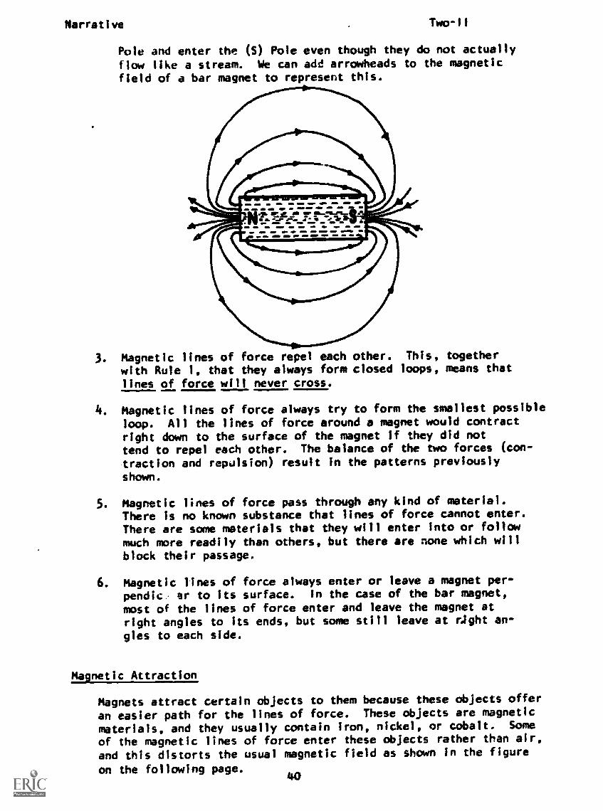
Magnets attract certain objects to them because these objects offer
an easier path for the lines of force. These objects are magnetic
materials, and they usually contain iron, nickel, or cobalt. Some
of the magnetic lines of force enter these objects rather than air,
and this distorts the usual magnetic field as shown in the figure
on the following page.40
Narrative RV COPY 1MARETwo- I I
The tendency is for the lines of force to try to contract (Rule 4)but still pass through the magnetic substance, and the substanceis pulled to the magnet. Alternatively, we can think of the linesof force converting the magnetic material (here the soft iron)into another magnet. Let's see how this works.
If two bdr magnets are placed end to end with two like poles to-gether (both N poles or both S poles), the lines of force willrepel each other and will cause the magnets to try to push apart.
LIKE POLES REPEL
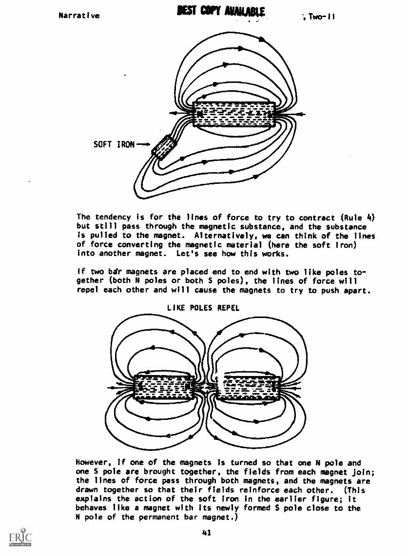
However, if one of the magnets Is turned so that one N pole andone S pole are brought together, the fields from each magnet Join;the lines of force pass through both magnets, and the magnets aredrawn together so that their fields reinforce each other. (Thisexplains the action of the soft iron in the earlier figure; itbehaves like a magnet with its newly formed S pole close to theN pole of the permanent bar magnet.)
41

Narrative au Two -11
UNLIKE POLES ATTRACT
Flux Density
The total strength of the magnetic field is indicated by the flux.
A strong field has many lines of flux, but a weak field contains
few lines of flux. A measure of the magnetic field at any point
is the flux density. Flux density refers to the number of linesof force present through any unit of area perpendicular to the
field. We might have a square inch with just one line of force
(low flux d Isity) at some distance from a magnet, but near apole (end), the magnet might have a flux density of tens of
flux lines crossing one-hundredth of a square inch. As you can
see from the pattern of flux lines around a magnet, the flux
density is greatest at the poles of the magnet.
AT THIS POINT, YOU MAY TAKE THE PROGRESS CHECK, OR YOU MAY STUDY
ANY OF THE OTHER RESOURCES LISTED. IF YOU TAKE THE PROGRESS
CHECK AND ANSWER ALL OF THE QUESTIONS CORRECTLY, GO TO THE NEXT
LESSON. IF NOT, STUDY ANY METHOD OF INSTRUCTION YOU WISH UNTIL
YOU CAN ANSWER ALL THE QUESTIONS CORRECTLY.
42

P. I. wo -II1.44`
PROGRAMMED INSTRUCTIONLESSON II
t4,1nr sm
TEST FRAMES ARE 41 AND 45. AS BENRE, GO FIRST TO TEST FRAME 41 ANDSEE IF YOU CAN ANSWER ALL THE QUESTIONS THERE. FOLLOW THE DIRECTIONSGIVEN AFTER THE TEST FRAME.
1. You have learned that one method of producing an EMF is by chem-ical action.
Producing an EMF by chemical action is employed in a componentcalled a or . (Either order)
or battery)
2. Looking at your power supply you can see that it receives itsenergy without requiring a cell or battery. This energy is pro-duced far away by converting mechanical energy into electricalenergy utilizing magnetism.
The voltage for your power supply is produced utilizing
(Magnetism)
3. For our purposes, magnetism is the property of some metals to beattracted by a nearby magnet.
If a metal is attracted by a magnet, the forde of attraction isindicative of
(magnetism)
4. All matter can be classified as either magnetic or nonmagnetic..Metals that are strongly attracted by a magnet are classified asmagnetic. All other matter is classified as nonmagnetic.
A wooden pencil is a form of material.
(nonmagnetic)

R.I.
5.
ain UNABLE
NATURAL
Two -I1
ARTIFICIAL
A natural magnet and the so-called artificial magnet are our twosources of magnetism. The two sources of magnetism are the
magnet and the magnet. (either order)
(natural - artificial)
6. We seldom use natural magnets today, because we can produce much
better and cheaper artificial magnets. All man-made magnets are
classified as magnets.
(artificial)
7. The poles of a magnet are the ends where most of the magnet force
is concentrated. If a magnet is sprinkled with iron filings,most of the filings will be attracted to and collected at the
poles. If you sprinkle iron filings in the area around a magnet,you will notice that the filings collect in a definite pattern.
This pattern is caused by an invisible magnetic field, and its
associated magnetic force, that surrounds all magnets.
t
f tti / 3/4 I1 L /1. 7. - , % ) / /
%
4.7
%;:....% 1
."1 ;".' Ai/.%"
The magnetic field concentrates around the end of the magnets
called
(poles)
44
P.1.
8. The lines formed by the magnetic field are calledof flux (also called lines of force); a definite,force exists between these lines and any magnetic
Two-11
magnetic linesmeasurablematerial.
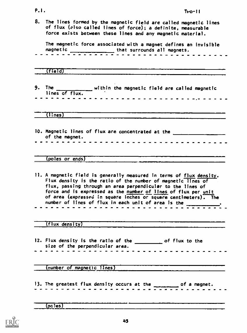
The magnetic force associated with a magnet defines an invisiblemagnetic that surrounds all magnets.
Meld)
9. The within the magnetic field are called magneticlines of flux.
(lines)
10. Magnetic lines of flux are concentrated at theof the magnet.
(poles or ends)
11. A magnetic field is generally measured In terms of flux densitFlux density is the ratio of the number of magnetic lines oflux, passing through an area perpendicular to the lines offorce and is expressed as the number of lines of flux per unitof area (expressed in square inches or square centimeters). Thenumber of lines of flux in each unit of area is the
(flux density)
12. Flux density is the ratio of the of flux to thesize of the perpendicular area.
nun--7-173rag s
13. The greatest flux density occurs at the of a magnet.
(pales)
45
P.1. Two-11
14. Flux density is the number of magnetic lines of flux in
of area.
each unit
15. Flux density is
(the number of lines of magnetic flux in each unit of area)
16. The compass that you used as a Boy Scout or camper had a perma-
nent magnet as its needle. The end of the needle that isattracted to the north pole of the Earth was at one time called
the north seeking_pole. Today, the word seeking has been
dropped; it is called the north Rple of the magnet.
Any magnet that is suspended, and is free to turn, will align
itself with the Earth's magnetic field. The end of the magnet
that points to the north is the pole of the magnet.
(north)
17. The end of the magnet that points to the south is theof the magnet.
(south pole)
18. The greatest flux density occurs at the of
the magnet.
(poles)
46
P.1. Two-11
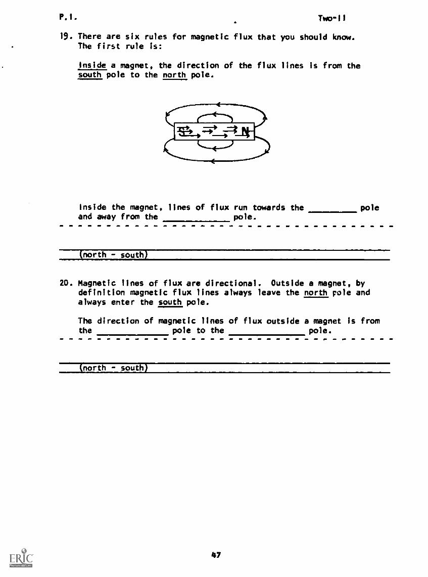
19. There are six rules for magnetic flux that you should know.The first rule is:
Inside a magnet, the direction of the flux lines is from thesouth pole to the north pole.
Inside the magnet, lines of flux run towards the poleand away from the pole.
(north - south)
20. Magnetic lines of flux are directional. Outside a magnet, bydefinition magnetic flux lines always leave the north role andalways enter the south pole.
The direction of magnetic lines of flux outside a magnet Is fromthe pole to the pole.
(north - south)

P.1. Two-11
21. Using arrows, indicate on the following magnetic field the direc-
tion of magnetic lines of flux - both inside and outside the
magnet.
22. State the rule pertaining to the direction of magnetic flux
lines.
(Lines of flux travel from north to south outside the magnet
and from south to north inside the magnet.)
23. An electrical circuit forms a complete path for current flow; a
magnetic circuit forms a closed loop for each line of flux.
Thus we have stated the second rule.
Magnetic lines of flux form loops.
(closed)
48

P.1. Two-II
24. Flux lines are never broken. Their path may be altered by anoutside force, causing the shape of the magnetic field to change,but each line of force will remain unbroken, each forming a
(closed loop)
25. Write true or false before each statement.
a. Lines pf flux form incomplete loops.b. Lines of flux form closed loops.c. Lines of flux follow a straight path.
(a. false; b. true; c. false/
26. For the third rule, we find that lines of force polarized inthe same direction repel each other. This repulsion is whatgives the magnetic field its expanded, uniform, or symmetricalpattern.
In a magentic field, the individual lines of force of the samepolarization each other.
(repel)
49
P.1. ers Off 'mai Two-11
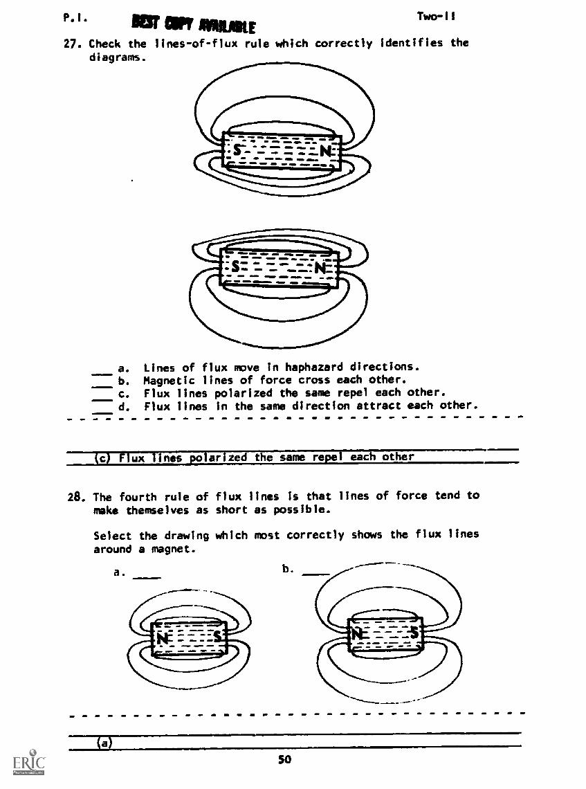
27. Check the lines-of-flux rule which correctly identifies thediagrams.
a. Lines of flux move in haphazard directions.b. Magnetic lines of force cross each other.c. Flux lines polarized the same repel each other.d. Flux lines in the same direction attract each other.
(c) Flux lines Solarized the same repel each other
28. The fourth rule of flux lines is that lines of force tend tomake themselves as short as possible.
Select the drawing which most correctly shows the flux linesaround a magnet.
a. b.
50

P.I.
29. Write true or false.
t.s, 1711P-ii
a. Lines of flux tend to expand.b. Lines of flux tend to contract.c. Lines of flux always travel long distances.
(a. false; b. true; c. false)
30. The fifth rule of flux lines is that there Is no known substancewhich will stop the lines of force.
Which of the following could be used to block lines of flux?
a. soft ironb. cobaltc. a copper shieldd. none of the above
(d) none of the above
31. Simply stated, magnetic lines of flux will pass through allmaterial.
Magnetic lines of flux will pass
----(Ihrou2p all material)
32. State the rule about insulation from flux lines.
(Magnetic flux lines pass through ail material.)
33. The last of the six rules is that flux lines always enter orleave a magnet perpendicular to its surface.
Lines of flux always or
at right angles to its surface.
a
(enter - leave - magnet)
51
P.1. INV AVARAKE Two-11
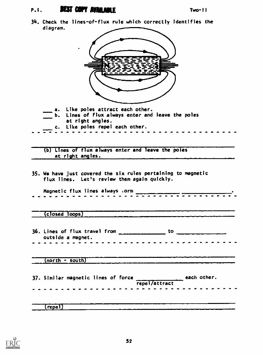
34. Check the lines-of-flux rule which correctly identifies thediagram.
a. Like poles attract each other.b. Lines of flux always enter and leave the poles
at right angles.c. Like poles repel each other.
(b) Lines of flux always enter and leave the polesat right angles.
35. We have Just covered the six rules pertaining to magneticflux lines. Let's review them again quickly.
Magnetic flux lines always lorm
(closed loops1
36. Lines of flux travel fromoutside a magnet.
(north - sout1i)
37. Similar magnetic lines of forcerepel/attract
each other.
Irepel)
52

P.I.
38. Magnetic lines of force always form theloops possible.
Two- I
(smallest)
39. Magnetic lines of force pass
(through all material)
40. Magnetic lines of force enter and leave a magnet at
(right angles or perpendicular to the surfii
41. State the six rules pertaining to magnetic flux lines.
Magnetic flux lines always:
1.
2.
3.
4.
5.
6.
(THIS IS A TEST FRAME. COMPARE YOUR ANSWERS WITH THE CORRECTANSWERS GIVEN AT THE TOP OF THE NEXT PAGE.)
53
P.I. Two-II
ANSWERS - TEST FRAME 41 *
1. Form closed loops.
2. Leave the north pole and enter the south pole.
3. Repel each other.
4. Try to form the smallest possible loop.
5. Pass through any material.
6. Enter or leave a magnet perpendicular to its surface.
* Answers may be in any order
IF ALL YOUR ANSWERS MATCH THE CORRECT ANSWERS, YOU MAY GO
ON TO TEST FRAME 45. OTHERWISE, GO BACK TO FRAME 1 AND
TAKE THE PROGRAMMED SEQUENCE BEFORE TAKING TEST FRAME 41
AGAIN.
42. Before we complete this lesson, let's take up the two laws of
magnetic poles for magnetism:
- Like poles repel each other.- Unlike poles attract each other.
Consider two permanent magnets. If you try to put the two north
poles together, they will each other.
(rape!)
43. If the north pole and south pole are placed together, they will
each other.
(attract
54
P.I. Two-II
44. As we said before, these are known as the law of magneticpoles for magnetism.
a. like polesb. unlike poles
117 1 ke po es repel; b. un ;Ice po es attract
45. State the laws of magnetic poles.
(THIS IS A TEST FRAME. COMPARE YOUR ANSWER WITH THE CORRECTANSWER GIVEN AT THE TOP OF THE NEXT PAGE.)
55

P.I. Two-II
ANSWERS - TEST FRAME 45
Like poles repel,
unlike poles attract.
fF YOUR ANSWER IS INCORRECT, GO BACK TO FRAME 4R AND TAKE
THE PROGRAMMED SEQUENCE.
IF YOUR ANSWER IS CORRECT, YOU MAY TAKE THE PROGRESS CHECK,OR YOU MAY STUDY ANY OF THE OTHER RESOURCES LISTED. IF YOU
TAKE THE PROGRESS CHECK AND ANSWER ALL THE QUESTIONS COR-RECTLY, GO ON TO THE NEXT LESSON. IF NOT, STUDY ANY METHODOF INSTRUCTION YOU WISH UNTIL YOU CAN ANSWER ALL THE QUESTIONS
CORRECTLY.
56
Summery Two-11
SUMMARYLESSON 11
IEST COPY ARAM
Magnetism
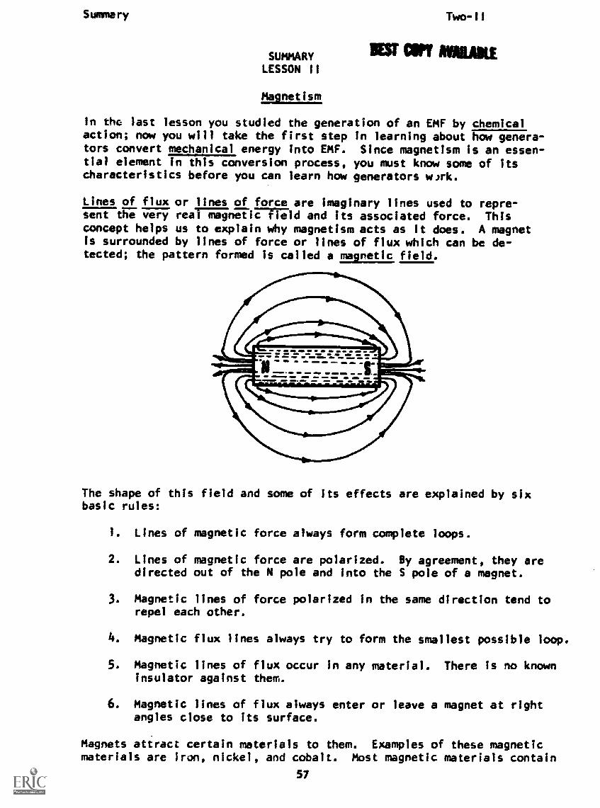
In the last lesson you studied the generation of an EMF by chemicalaction; now you will take the first step in learning about how genera-tors convert mechanical energy into EMF. Since magnetism is an essen-tial element in this conversion process, you must know some of itscharacteristics before you can learn how generators wok.
Lines of flux or lines of force are imaginary lines used to repre-sent the very real and its associated force. Thisconcept helps us to explain why magnetism acts as it does. A magnetis surrounded by lines of force or lines of flux which can be de-tected; the pattern formed is called a magnetic field.
The shape of this field and some of its effects are explained by sixbasic rules!
1. Lines of magnetic force always form complete loops.
2. Lines of magnetic force are polarized. By agreement, they aredirected out of the N pole and into the S pole of a magnet.
3. Magnetic lines of force polarized in the same direction tend torepel each other.
Magnetic flux lines always try to form the smallest possible loop.
5. Magnetic lines of flux occur in any material. There is no knowninsulator against them.
6. Magnetic lines of flux always enter or leave a magnet at rightangles close to its surface.
Magnets attract certain materials to them. Examples of these magneticmaterials are iron, nickel, and cobalt. Most magnetic materials contain
57
Summary Two
one oi;a4nor4 6f.04se three elements.
Two magnets will also attract each other if they are placed near each
other with opposite (N and S) poles close together, but they will repel
each other if one of them is turned around (N and N or S and S). The
law which states this effect is similar to that indicated by Coulomb's
Law. It is called the law of magnetic poles and is stated as: Like
poles repel; unlike poles attract.
The amount of force (attraction or repulsion) a magnet can exert
depends on the strength of its magnetic field. The strength of the
magnetic field at Ey. point is indicated by the flux density. flux
density is the number of lines of force per unit area perpendicular
to the field, and will vary with the distance from a magnetic pole.
Flux density for any magnet is always greatest at its poles, and de-
creases as distance from the poles increases, again in a manner similar
to that described by Coulomb's Law for charges.
AT THIS POINT, YOU MAY TAKE THE LESSON PROGRESS CHECK, OR YOU MAY
STUDY THE LESSON NARRATIVE OR THE PROGRAMMED INSTRUCTION OR BOTH.
IF YOU TAKE THE PROGRESS CHECK AND ANSWER ALL OF THE QUESTIONS
CORRECTLY, GO TO THE NEXT LESSON. IF NOT, STUDY ANOTHER METHODOF INSTRUCTION UNTIL YOU CAN ANSWER ALL THE QUESTIONS CORRECTLY.
58

BASIC ELECTRICITY AND ELECTRONICS
INDIVIDUALIZED LEARNING SYSTEM
MODULE TWO
LESSON ill
Electromagnetic Induction
Study Booklet
59

Overview Two-III
OVERVIEW
LESSON III
Electromagnetic Induction
In this lesson you will study and learn about the following:
-left-hand rule for generators
-magnetic mechanical generation
Each of the above topics will be discussed in the order listed.
As you proceed through this lesson, observe and follow directions
carefully.
BEFORE YOU START THIS LESSON, PREVIEW THE LIST OF STUDY RESOURCES
ON THE NEXT PAGE.
60

Study Resources Two-III
LIST OF STUDY RESOURCES
LESSON III
To learn the material in this lesson, you have the option of choosing,
according to your experience and preferences, any or all of the following:
STUDY BOOKLET:
Lesson Narrative
Programmed Instructior
Lesson Summary
ENRICHMENT MATERIAL:
NAVPERS 99400A-la "Basic Electricity, Direct Current."
Fundamentals of Electronics. Bureau of Naval Personnel.
Washington, D.C.; U.S. Government Printing Office, 1965.
AUDIO-VISUAL:
Sound/Slide - "Electromagnetic Induction"
Remember, you may study any or all of these that you feel are necessary
to answer all Progress Check questions correctly. Do not forget that
in one sense of the word your instructor is a living resource; perhaps
the best. Call him if you have any kind of a problem.
YOU MAY NOW STUDY ANY OR ALL OF THE RESOURCES LISTED ABOVE. YOU MAY
TAKE THE PROGRESS CHECK AT ANY TIME.
61
Narrative Two-ill
NARRATIVELESSON III
Electromagnetic Induction
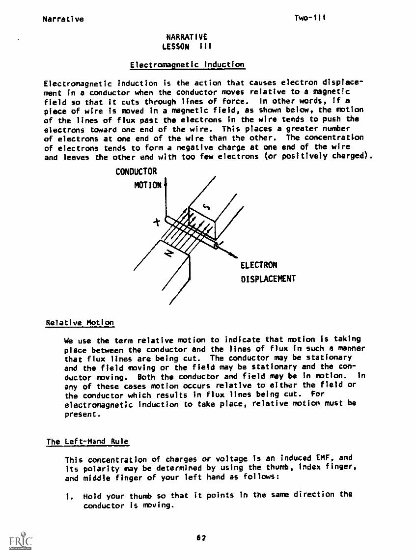
Electromagnetic induction is the action that causes electron displace-ment in a conductor when the conductor moves relative to a magnet!c
field so that it cuts through lines of force. In other words, if apiece of wire is moved in a magnetic field, as shown below, the motion
of the lines of flux past the electrons In the wire tends to push theelectrons toward one end of the wire. This places a greater numberof electrons at one end of the wire than the other. The concentration
of electrons tends to form a negative charge at one end of the wireand leaves the other end with too few electrons (or positively charged).
CONDUCTOR
MOTION
ELECTRON
DISPLACEMNT
Relative Motion
We use the term relative motion to indicate that motion is taking
place between the conductor and the lines of flux In such a mannerthat flux lines are being cut. The conductor may be stationaryand the field moving or the field may be stationary and the con-
ductor moving. Both the conductor and field may be In motion. in
any of these cases motion occurs relative to either the field orthe conductor which results in flux lines being cut. For
electromagnetic induction to take place, relative motion must be
present.
The Left-Hand Rule
This concentration of charges or voltage is an induced EMS', and
its polarity may be determined by using the thumb, index finger,
and middle finger of your left hand as follows:
1. Hold your thumb so that it points in the same direction the
conductor is moving.
62
Narrative Two-ill
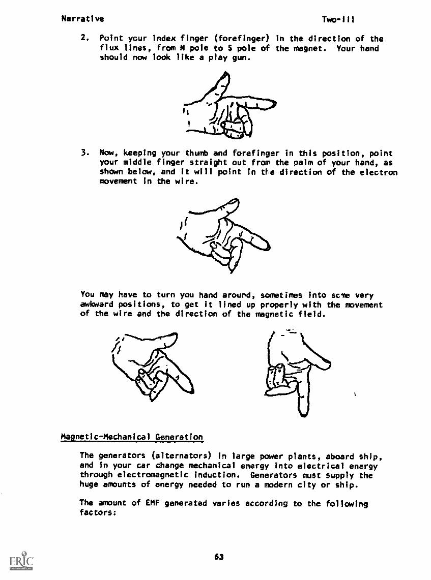
2. Point your index finger (forefinger) in the direction of theflux lines, from N pole to S pole of the magnet. Your handshould now look like a play gun.
3. Now, keeping your thumb and forefinger in this position, pointyour middle finger straight out from the palm of your hand, asshown below, and it will point in ths direction of the electronmovement in the wire.
You may have to turn you hand around, sometimes into scte veryawkward positions, to get it lined up properly with the movementof the wire and the direction of the magnetic field.
Magnetic-Mechanical Generation
The generators (alternators) in large power plants, aboard ship,and in your car change mechanical energy into electrical energythrough electromagnetic induction. Generators must supply thehuge amounts of energy needed to run a modern city or ship.
The amount of EMF generated varies according to the followingfactors:
63
Narrative Two-III
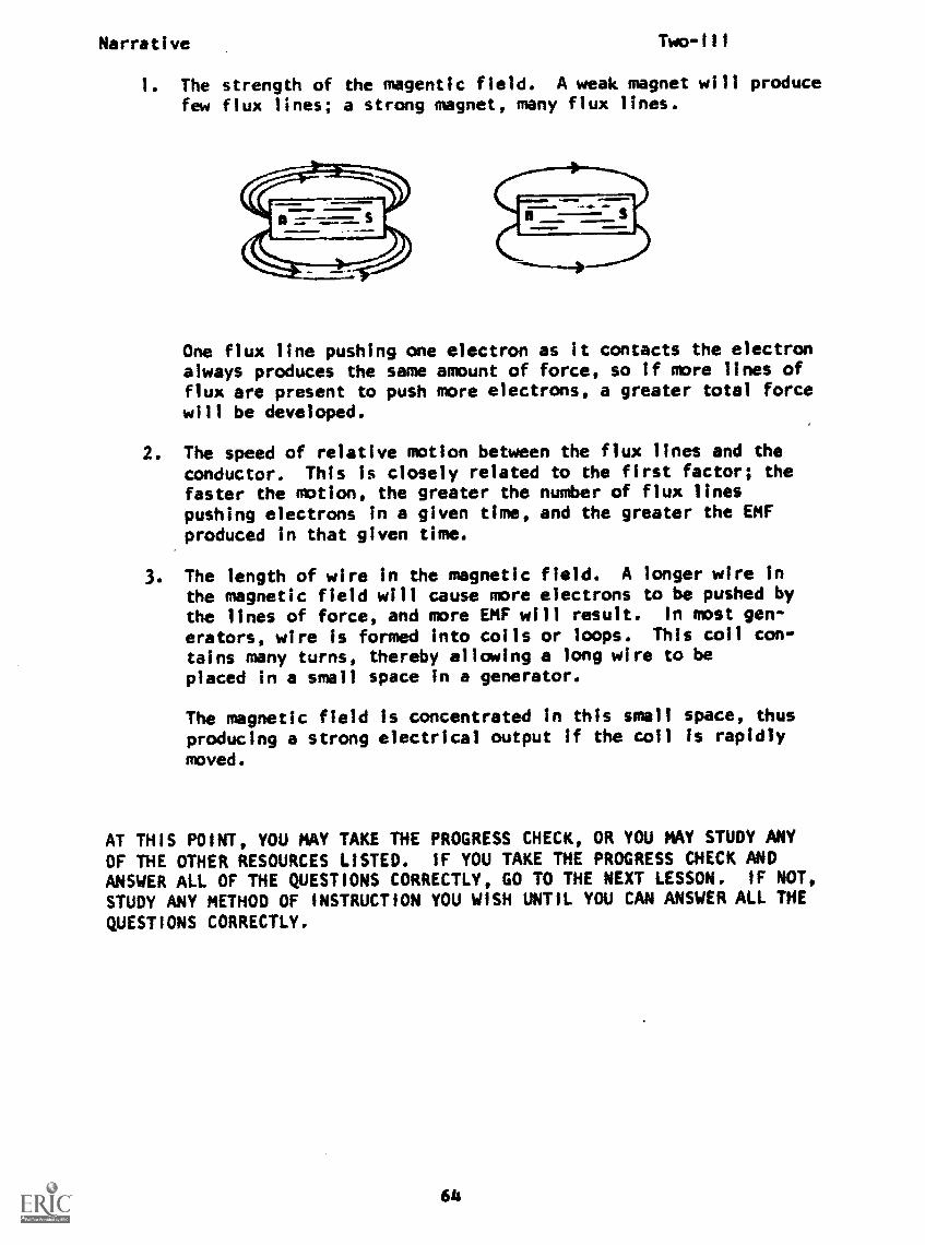
I. The strength of the magentic field. A weak magnet will producefew flux lines; a strong magnet, many flux lines.
One flux line pushing one electron as it contacts the electronalways produces the same amount of force, so if more lines offlux are present to push more electrons, a greater total forcewill be developed.
The speed of relative motion between the flux lines and the
conductor. This is closely related to the first factor; thefaster the motion, the greater the number of flux linespushing electrons in a given time, and the greater the EMFproduced in that given time.
3. The length of wire in the magnetic field. A longer wire inthe magnetic field will cause more electrons to be pushed bythe lines of force, and more EMF will result. In most gen-
erators, wire is formed into coils or loops. This coil con-tains many turns, thereby allowing a long wire to beplaced in a small space in a generator.
The magnetic field is concentrated in this smell space, thusproducing a strong electrical output if the coil is rapidly
moved.
AT THIS POINT, YOU MAY TAKE THE PROGRESS CHECK, OR YOU MAY STUDY ANY
OF THE OTHER RESOURCES LISTED. IF YOU TAKE THE PROGRESS CHECK ANDANSWER ALL OF THE QUESTIONS CORRECTLY, GO TO THE NEXT LESSON. IF NOT,
STUDY ANY METHOD OF INSTRUCTION YOU WISH UNTIL YOU CAN ANSWER ALL THE
QUESTIONS CORRECTLY.
64

P.1. Two -Ill
PROGRAMMED INSTRUCTIONLESSON III
Electromagnetic Induction
TEST FRAMES ARE 17, 22 AND 26. AS BEFORE, GO FIRST TO TEST FRAME 17AND SEE IF YOU CAN ANSWER ALL THE QUESTIONS THERE. FOLLOW THE DIREC-TIONS GIVEN AFTER THE TEST FRAME.
1. Definition of electromagnetic induction: Electromagnetic induc-tion is the action which causes electron displacement In a con-ductor when the conductor moves relative to a magnetic field andcuts through lines of force.
An EMF Is produced by moving a conductor through a
(magnetic field)
2. State the definition of electromagnetic induction.
(The action which causes electron displacement in a conductorwhen it moves relative to a magnetic field and cuts throughlines of force.)
65
P.1.
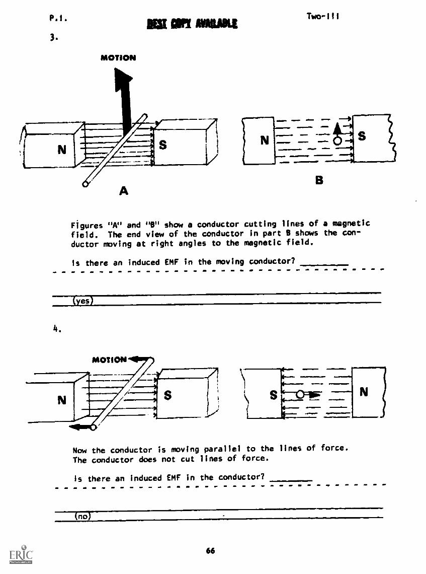
3.
MOTION
Two -I11
B
Figures "A" and "B" show a conductor cutting lines of a magnetic
field. The end view of the conductor in part B shows the con-
ductor moving at right angles to the magnetic field.
Is there an induced EMF in the moving conductor?
yes)
4.
Now the conductor is moving parallel to the lines of force.
The conductor does not cut lines of force.
Is there an induced EMF in the conductor?
(no)
66
Phi.
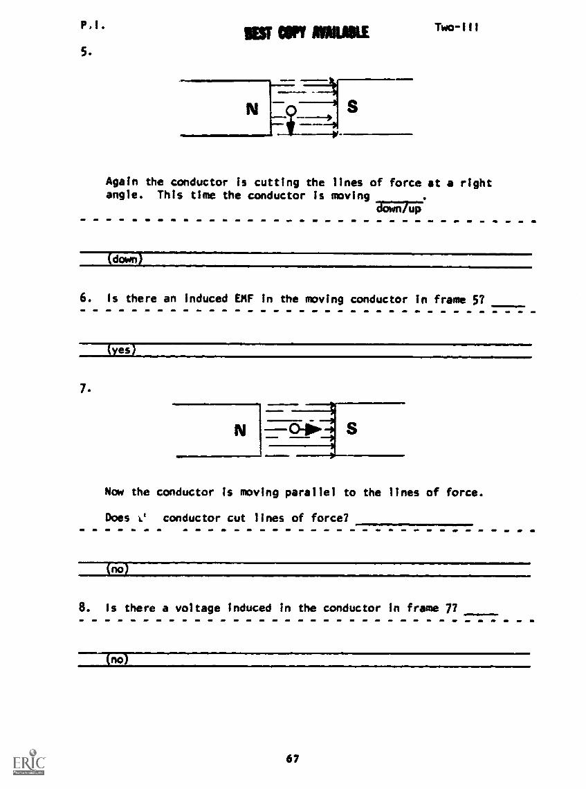
5.
PEST COPY IINKMETwo-Ill
Again the conductor is cutting the lines of force at a rightangle. This time the conductor Is moving
downlup
(down)
6. Is there an induced EMF in the moving conductor in frame 5?
(yes)
Now the conductor Is moving parallel to the lines of force.
Does t' conductor cut lines of force?
(no
8. Is there a voltage induced in the conductor In frame 7?
TnoJ
67
P.I. .Two-III
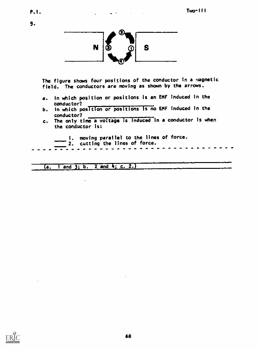
9.
S®,The figure shows four positions of the conductor in a magnetic
field. The conductors are moving as shown by the arrows.
a. In which position or positions is an EMF induced in the
conductor?b. In which position or positions Is no EMF induced In the
conductor?c. The only time a voltage is induced In a conductor is when
the conductor is:
1. moving parallel to the lines of force.2. cutting the lines of force.
Ta. 1 and 3; b. 2 and 4; c. 2.)
68
P.1.
INST COPY AWMIABLE10.
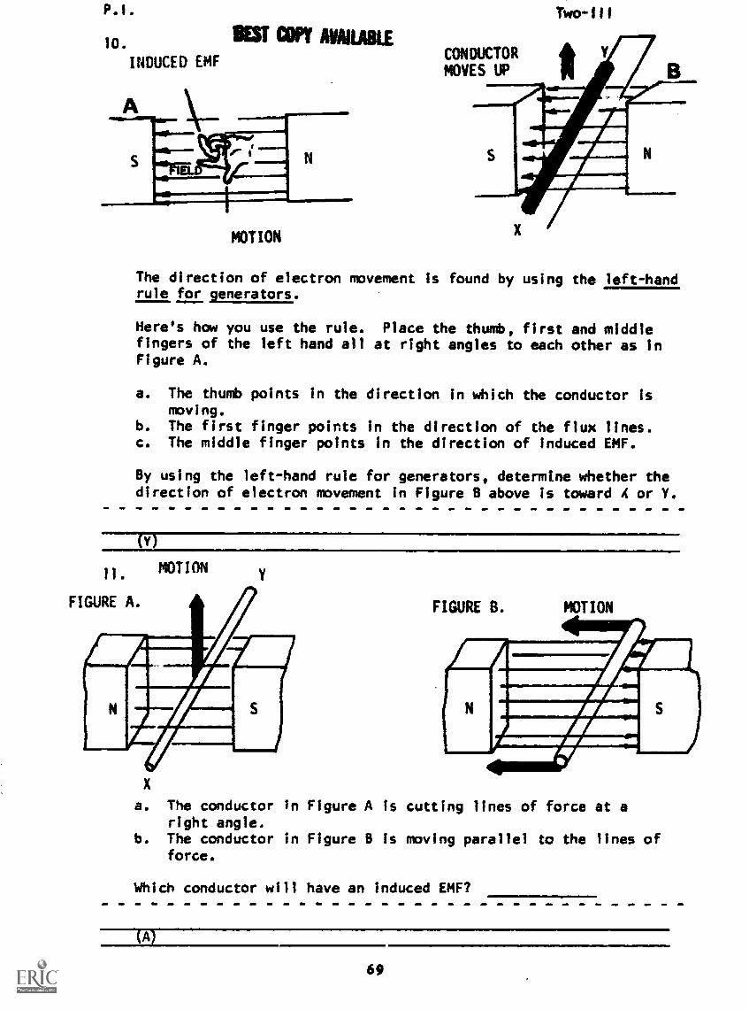
INDUCED EMF
MOTION
CONDUCTORMOVES UP
Two-111
The direction of electron movement Is found by using the left-handrule for generators.
Here's how you use the rule. Place the thumb, first and middlefingers of the left hand all at right angles to each other as inFigure A.
a. The thumb points in the direction in which the conductor ismoving.
b. The first finger points in the direction of the flux lines.c. The middle finger points in the direction of induced EMF.
By using the left-hand rule for generators, determine whether thedirection of electron movement in Figure B above is toward A or Y.
(Y)
MOTION
FIGURE A. FIGURE B. MOTION
a. The conductor in Figure A is cutting lines of force at aright angle.
b. The conductor in Figure B is moving parallel to the lines offorce.
Which conductor will have an induced EMF?
(A)
69
P.1. 1311 art AMIABLE
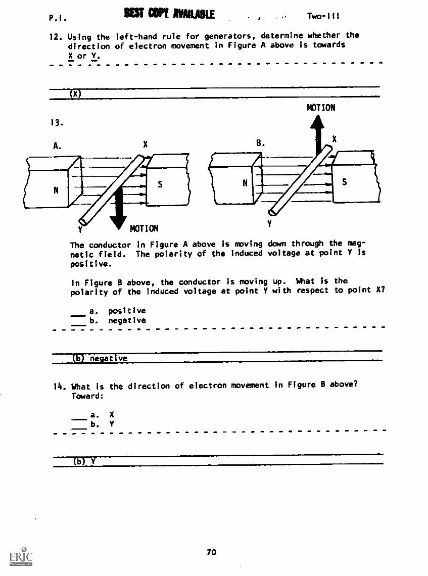
12. Using the left-hand rule for generators,direction of electron movement in FigureX or I.
Two-Ill
determine whether theA above is towards
X
Y MOTION
The conductor in Figure A above is moving down through the mag-
netic field. The polarity of the induced voltage at point Y is
positive.
MOTION
Y
In Figure B above, the conductor is moving up. What is thepolarity of the induced voltage at point Y with respect to point X?
11111=1.a. positiveb. negative
(14 negative
14. What is the direction of electron movement In Figure B above?
Toward:
a. X
b.
(b) Y
70

P.1.
15.
The illustration shows four positions of the conductor. A volt-age is induced in the conductor when the conductor is moving asin 1 and 3.
How do the polarities of induced voltage in Positions 1 and 3coma re?
a. sameb. opposite
(b) opposite
16.
MOTION
B.
NOTION
The illustrations show that when the conductor changes its direc-tion through the magnetic field, the of the inducedvoltage changes.
(pc ty)
71
P.I. Two-III
.
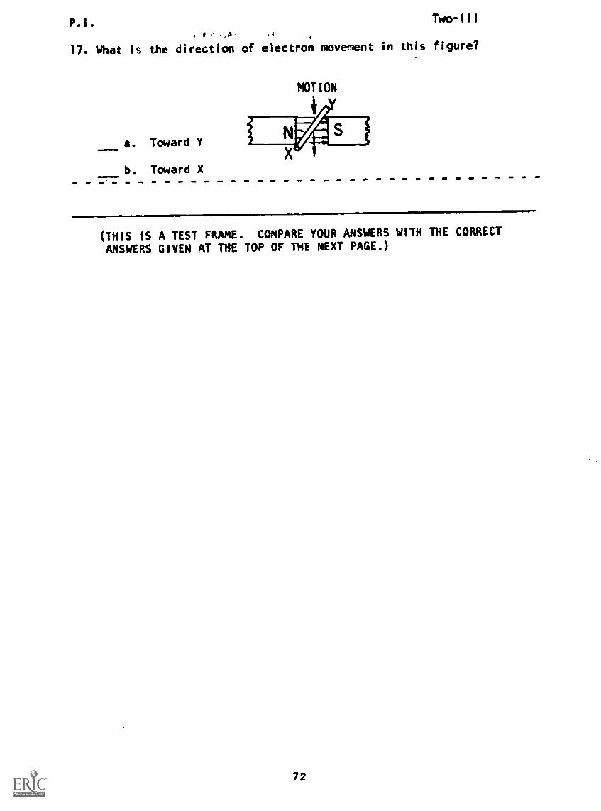
17. What is the direction of electron movement in this figure?
a. Toward Y
b. Toward X
POTION
(THIS IS A TEST FRAME. COMPARE YOUR ANSWERS WITH THE CORRECT
ANSWERS GIVEN AT THE TOP OF THE NEXT PAGE.)
72

P.I.
18.
f :111,4
IE3T COPY AVANUUMUE Two -III
ANSWERS - TEST FRAME 17
a. Toward Y
IF YOUR ANSWER MATCHES THETEST FRAME 22. OTHERWISE,PROGRAMMED SEQUENCE BEFORE
CORRECT ANSWER, YOU MAY GO ON TOGO BACK TO FRAME 1 AND TAKE THETAKING TEST FRAME 17 AGAIN.
The illustration shows the conductor formed into a loop or coil.
When the black side is moving up, the white side is moving .
down
19. The voltage induced in the black side
induced in the white side.aids/opposes
the voltage
(aids)
73

S
P.1.
20.
Figure A
C
D.
In Figure A above, point D is positive with respect to point C.
Two-Ill
a. In Figure B, point D is
b. In Figure A, point A isc. In Figure B, point A is
with respect to point C.with respect to point B.with respect to point B.
21.
negative; b. negative; c. positive)
The Illustration above shows the two sides of the coil moving
parallel to the lines-of force.
When tbe coil Is in this
induced in the two sidescutting lines of force.
position, there Is voltagezero some
of the coil because the sidesare
(zero - are not)
74
P.I. BESTCM new22.
0A.
B.
C.
D
4
0
4 0
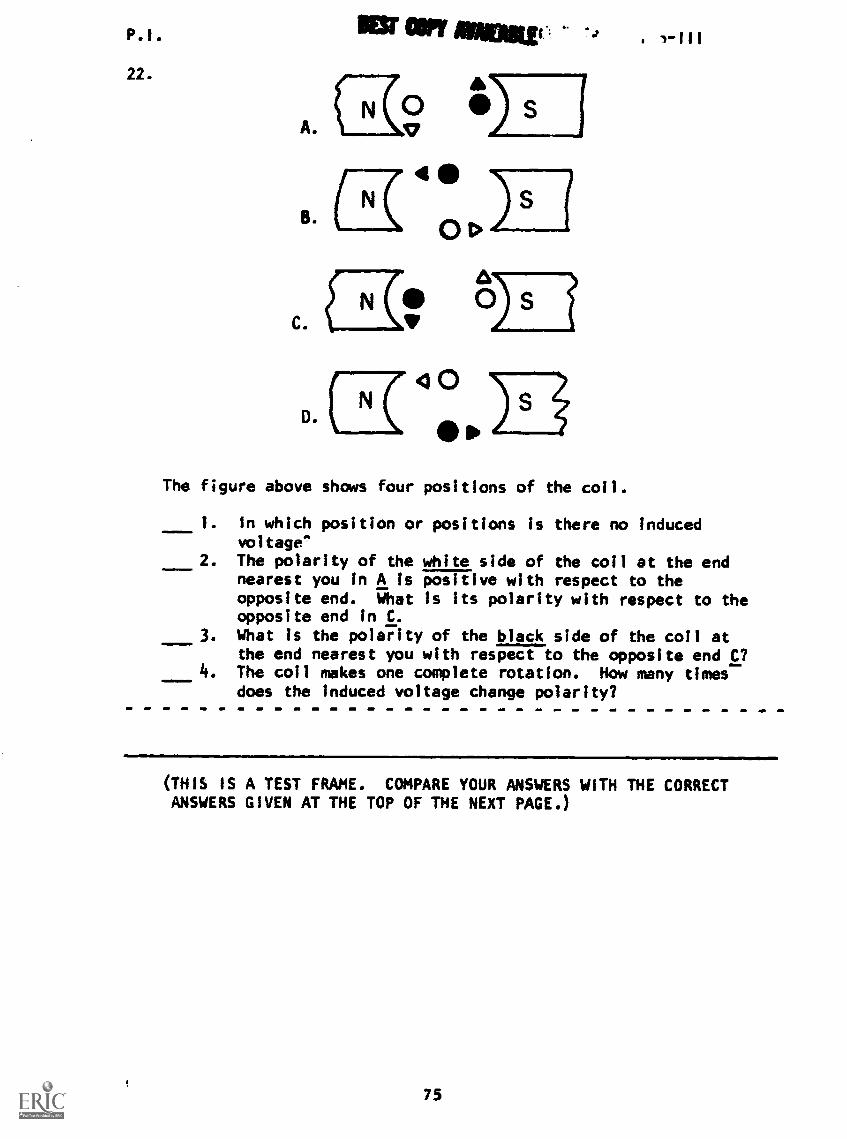
The figure above shows four positions of the coil.
3- I
1. In which position or positions is there no inducedvoltage'
2. The polarity of the white side of the coil at the endnearest you in A is positive with respect to theopposite end. What is its polarity with respect to theopposite end in C.
3. What is the polarity of the black side of the coil atthe end nearest you with respect to the opposite end C?The coil makes one complete rotation. How many timesdoes the induced voltage change polarity?
(THIS IS A TEST FRAME. COMPARE YOUR ANSWERS WITH THE CORRECTANSWERS GIVEN AT THE TOP OF THE NEXT PAGE.)
75
P.I. Two -III
ANSWERS - TEST FRAME 22
I. B and D
2. negative
3. positive
4. 2 times
IF ALL YOUR ANSWERS MATCH THE CORRECTTO TEST FRAME 26. OTHERWISE, GO BACKTHE PROGRAMMED SEQUENCE BEFORE TAKING
ANSWERS, YOU MAY GO ONTO FRAME 18 AND TAKETEST FRAME 22 AGAIN.
23. A.
B.
N
N
Irm
Om"
'wen'111.4111011
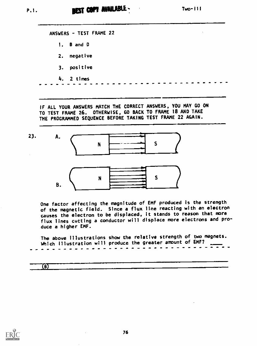
One factor affecting the magnitude of EMF produced is the strength
of the magnetic field. Since a flux line reacting with an electron
causes the electron to be displaced, it stands to reason that more
flux lines cutting a conductor will displace more electrons and pro-
duce a higher EMF.
The above illustrations show the relative strength of two magnets.
Which illustration will produce the greater amount of EMF?
76
P.I. MST WY AVAILABLE Two-111
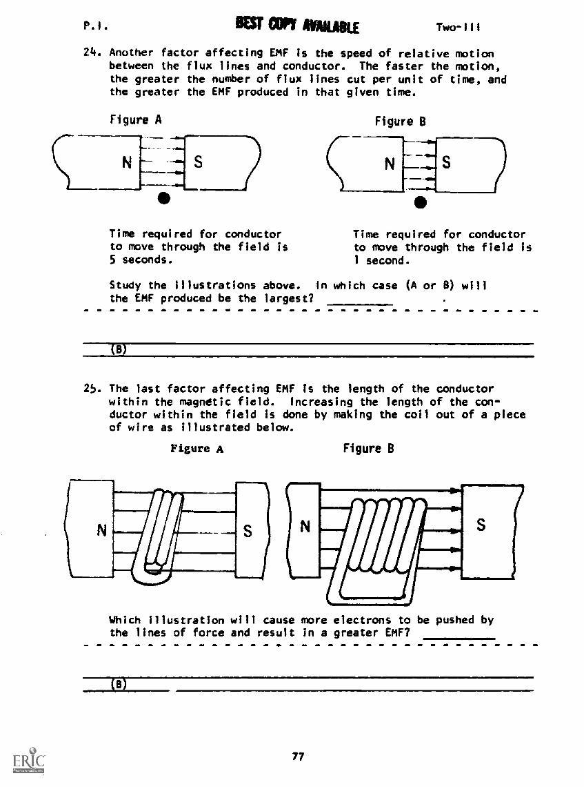
24. Another factor affecting EMF is the speed of relative motionbetween the flux lines and conductor. The faster the motion,the greater the number of flux lines cut per unit of time, andthe greater the EMF produced in that given time.
Figure A Figure B
S
Time required for conductorto move through the field is5 seconds.
Time required for conductorto move through the field is1 second.
Study the illustrations above. In which case (A or 8) willthe EMF produced be the largest?
CB
25. The last factor affecting EMF is the length of the conductorwithin the magnetic field. Increasing the length of the con-ductor within the field is done by making the coil out of a pieceof wire as illustrated below.
Figure A Figure B
Which illustration will cause more electrons to be pushed bythe lines of force and result in a greater EMF?
(a)
77

P.I.:tr;7 Two-III
26. The three factors that affect the strength of an induced
EMF are:
strength of the field, of
relative motion, and the length of in the
magnetic field.
(THIS IS A TEST FRAME. COMPARE YOUR ANSWERS WITH THE CORRECT
ANSWERS GIVEN AT THE TOP OF THE NEXT PAGE.)
78
P.I. Two-III
ANSWERS - TEST FRAME 26
Magnetic - speed - wire
IF ANY OF YOUR ANSWERS ARE INCORRECT, GO BACK TO FRAME 23 ANDTAKE THE PROGRAMMED SEQUENCE.
IF YOUR ANSWERS ARE CORRECT, YOU MAY TAKE THE PROGRESS CHECK,OR YOU MAY STUDY ANY OF THE OTHER RESOURCES LISTED. IF YOUTAKE THE PROGRESS CHECK AND ANSWER ALL THE QUESTIONS CORRECTLY,GO ON TO THE NEXT LESSON. IF NOT, STUDY ANY METHOD OF INSTRUC-TION YOU WISH UNTIL YOU CAN ANSWER ALL THE QUESTIONS CORRECTLY.
79
Summary alf intglit
SUMMARYLESSON III
Two-III
Electromagnetic Induction
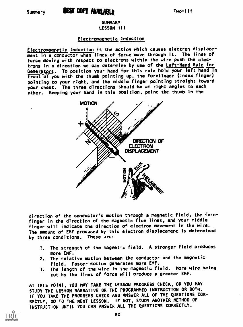
Electromagnetic Induction is the action which causes electron displace-ment in a conductor when lines of force move through it. The lines offorce moving with respect to electrons within the wire push the elec-trons in a direction we can dete-mine by use of the Left-Hand Rule for
Generators. To position your hand for this rule hol717&717;ft hanrn77;474177ou with the thumb pointing up, the forefinger (index finger)pointing to your right, and the middle finger pointing straight toward
your chest. The three directions should be at right angles to each
other. Keeping your hand in this position, point the thunt in the
direction of the conductor's motion through a magnetic field, the fore-
finger in the direction of the magnetic flux lines, and your middle
finger will indicate the direction of electron movement in the wire.
The amount of EMF produced by this electron displacement is determined
by three conditions. These are:
1. The strength of the magnetic field. A stronger field produces
more EMF.2. The relative motion between the conductor and the magnetic
field. Faster motion generates more EMF.
3. The length of the wire in the magnetic field. More wire being
cut by the lines of force will produce a greater EMF.
AT THIS POINT, YOU MAY TAKE THE LESSON PROGRESS CHECK, OR YOU MAY
STUDY THE LESSON NARRATIVE OR THE PROGRAMMED INSTRUCTION OR BOTH.
IF YOU TAKE THE PROGRESS CHECK AND ANSWER ALL OF THE QUESTIONS COR-
RECTLY, GO TO THE NEXT LESSON. IF NOT, STUDY ANOTHER METHOD OF
INSTRUCTION UNTIL YOU CAN ANSWER ALL THE QUESTIONS CORRECTLY.
SO

BASIC ELECTRICITY AND ELECTRONICS
INDIVIDUALIZED LEARNING SYSTEM
MODULE TWO
LESSON IV
Generating AC Volta9e
Study Booklet
81
Overview Two-IV
OVERVIEW
LESSON IV
Generating AC Voltage
In this lesson you will study and learn about the following:
- generation of alternating voltage
- amount of EMF
- graphing AC
-frequency
- more AC quantities
Each of the above topics will be discussed in the order listed.
As you proceed through this lesson, observe and follow directions
carefully.
BEFORE YOU START THIS LESSON, PREVIEW THE LIST OF STUDY RESOURCES
ON THE NEXT PAGE.
82

Study Resources Two-IV
LIST OF STUDY RESOURCES
LESSON IV
Generating AC Voltage
To learn the material in this lesson, you have the option of choosing,
according to your experience and your preferences, any or all of the
following:
STUDY BOOKLET:
Lesson Narrative
Programmed Instruction
Lesson Summary
ENRICHMENT MATERIALS:
NAVPERS 93400A-lb "Basic Electricity, Alternating Current."
Fundamentals of Electronics. Bureau of Naval Personnel.
Washington, D.C.: U.S. Government Printing Office, 1965.
You may study whatever learning materials you fefl are necessary to
answer the questions in the Lesson Progress Check. All your answers
must be correct before you can go to Lesson V. Remember your instruc-
tor is available at all times for any assistance you may need.
V1U PA PSO STUDY ANY OR ALL OF THE RESOURCES LISTED ABOVE. YOU MAY
TAKE THi PROGRESS CHECK AT ANY TIME.
83

Narrative Two -IV
NARRATIVELESSON IV
Generating AC Voltage
As you may already know, there are two different kinds of
electricity. The electricity used In your car is not thesame as the kind used In your house. The car uses directcurrent, the house uses alternating current.
Direct current (DC) is the type of electricity we have been
discussing so far. DC is the movement of electrons in only
one direction through the circuit path. Batteries generateDC from chemical action, and the associated EMF does no change
in polarity; also, the value usually is constant. In other
words, a DC voltage remains in the same direction and usuallyin value all the time. Recall the schematic symbol for a DC
source is: or .41--
Alternating current (AC) moves first in one direction, then
the other. Magnetic-mechanical generators produce AC, and the
associated EMF changes in polarity at intervals and changes in
value constantly. Stated another way, an AC voltage is always
changing in value and periodically changes in polarity. The
schematic symbol for an AC source Is a sine wave in a circle
as shown:...1D___
Generation of an Alternating Voltage
You will recall that when an EMF is generated by electromag-netic induction, three directional qtantities are present:
1. Lines of force, directed from the N pole to the S pole.
2. Motion of the wire with respect to the magnetic field
(relative motion).
3. Movement of the electrons within the wire.
The left-hand rule for generators indicates the directions o
these values. Applying this rule to a straight wire moving In
a magnetic field is a simple task, but most generators use coils
or loops of wire, and the rule is slightly more difficult to
apply. The following drawing shows this more clearly.
!ri this drawing, the loop of wire is rotating so that the part
of the wire between A and B is moving downward through the mag-
netic field near the N pole of the magnet. Applying the left-
hand rule to this part of the loop shows that electrons are
moved from A toward B as shown by the arrow. This means the
EMF must be positive (+) at A and negative (-) at B.
(See drawing next page)
84

Narrative mu cielrLE
PIVOT
INDUCED
POLARITIES
it
Own
*
Two-IV
The section of the wire between C and 0 is, at this same time,moving upward through the magnetic field by the 5 pole. Theleft-hand rule used here shows that the electrons are pushedfrom C toward 0, in the opposite direction to the current flowIn section AS of the loop. The EMF induc34 here is
tend tpositive
move(+)
at C and negative (-) at O. both induced voltages oelectrons around the loop in the same way.
As the loop continues to rotate in the magnetic fiteeld,
fl
it wnli
ill
reach a point where the wires do not cut through hux es,and no EMF will be induced in the coil.
A
This is because the wires are moving parallel to thethem.lines
of force at this instant and are not cutting through
As the loop rotates farther, the electrons start to move again.Checking their direction of motion with the left-hand rule showsthat they are now moving from 0 to C and from B to A, directlyopposite to their earlier direction In the wire. One-half turnafter our starting points, the loop will be in this position:
85

Narrative MOM AMU , .
PIVOT
4
I
. I
.
Ia.
a' I
a a
INDUCEDPOLARITIES
Two-1V
A is now the negative end of the loop and D the positive end,the exact opposite of the first situation. This reversal of
polarity is the difference between AC and DC.
As the loop continues to rotate, it cuts through flux linesuntil it reaches this position:
N(: ) S
Here the motion of the wire is again parallel to the directionof the flux lines and no EMF is generated.
As the loop keeps turning, it will return to its starting po-sition and repeat this cycle of operation so long as some me-chanical force keeps it moving.
Amount of EMF
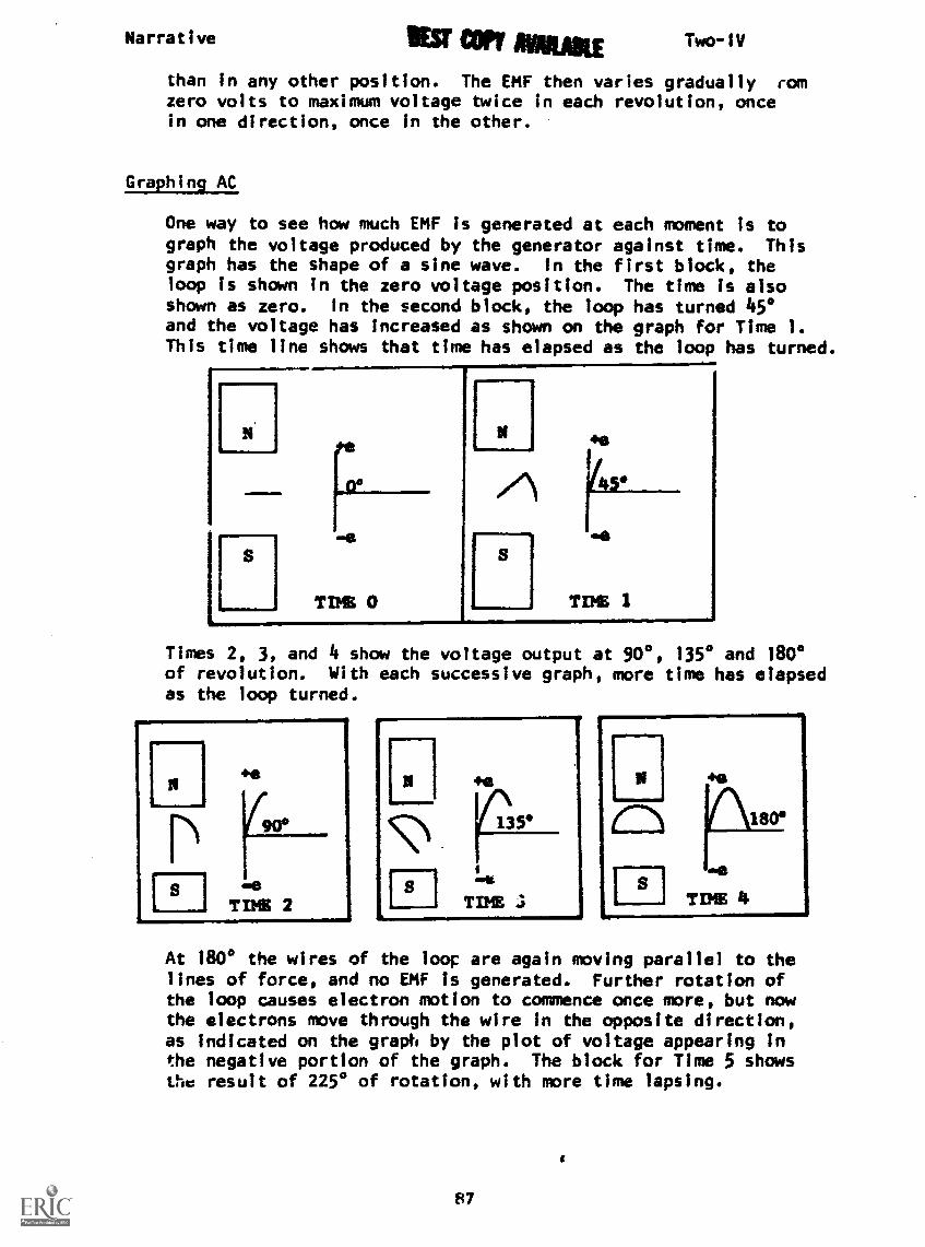
You have seen that the generated EMF is zero at two points duringeach full revolution of the loop, and that EMF is generated firstin one direction then in the other as the loop makes a completeturn. This EMF will be maximum at the two points where the wireloop is cutting through the flux lines at a right angle. This
is because the wire will cut more lines In a given instant here
86
Narrative IIESF AIMILIKE
than in any other position. The EMF then varies gradually romzero volts to maximum voltage twice in each revolution, oncein one direction, once in the other.
Two-IV
Graphin9 AC
One way to see how much EMF is generated at each moment is tograph the voltage produced by the generator against time. Thisgraph has the shape of a sine wave. In the first block, theloop is shown in the zero voltage position. The time is alsoshown as zero. In the second block, the loop has turned 490and the voltage has increased as shown on the graph for Time 1.This time line shows that time has elapsed as the loop has turned.
Times 2, 3, and 4 show the voltage output at 90°, 135° and 180°of revolution. With each successive graph, more time has elapsedas the loop turned.
At 1800 the wires of the loop are again moving parallel to thelines of force, and no EMF is generated. Further rotation ofthe loop causes electron motion to commence once more, but nowthe electrons move through the wire in the opposite direction,as indicated on the graph by the plot of voltage appearing Inthe negative portion of the graph. The block for Time 5 showsthe result of 225° of rotation, with more time lapsing.
87
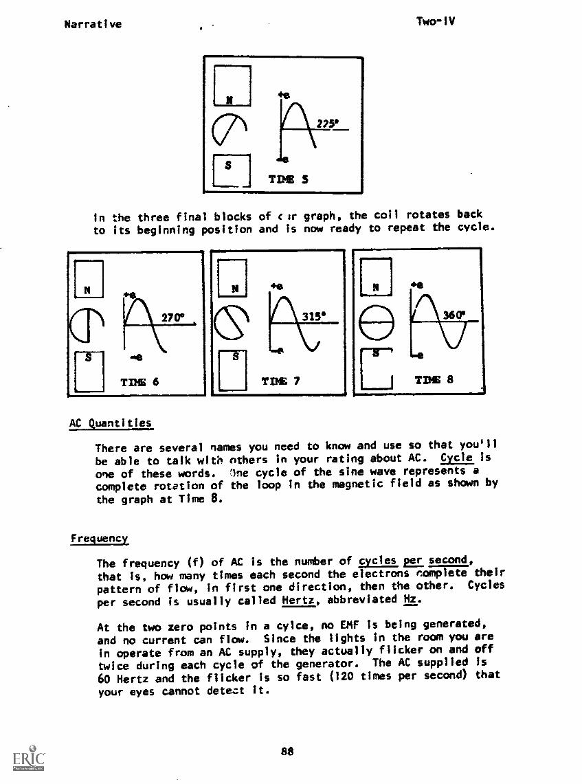
Narrative Two-IV
In the three final blocks of cir graph, the coil rotates back
to its beginning position and is now ready to repeat the cycle.
AC Quantities
There are several names you need to know and use so that you'll
be able to talk with others in your rating about AC. Cycle is
one of these words. lne cycle of the sine wave represents acomplete rotation of the loop in the magnetic field as shown by
the graph at Time 8.
Frequency
The frequency (f) of AC is the number of cycles Ls:second,
that is, how many times each second the electrons nomplete their
pattern of flow, in first one direction, then the other. Cycles
per second is usually called Hertz, abbreviated Hz.
At the two zero points in a cylce, no EMF is being generated,
and no current can flow. Since the lights In the room you are
in operate from an AC supply, they actually flicker on and off
twice during each cycle of the generator. The AC supplied is
60 Hertz and the flicker is so fast (120 times per second) that
your eyes cannot detect it.
88
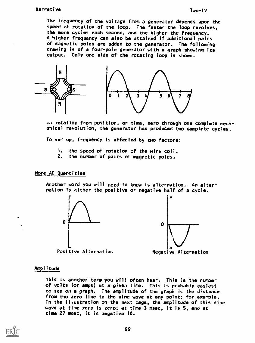
Narrative Two-IV
The frequency of the voltage from a generator depends upon thespeed of rotation of the loop. The faster the loop revolves,the more cycles each second, and tne higher the frequency.A higher frequency can also be attained if additional pairsof magnetic poles are added to the generator. The followingdrawing is of a four-pole generator with a graph showing itsoutput. Only one side of the rotating loop is shown.
i.. rotatinc from position, or time, zero through one complete mech-anical revolution, the generator has produced two complete cycles.
To sum up, frequency is affected by two factors:
1. the speed of rotation of the wire coil.2. the number of pairs of magnetic poles.
More AC quantities
Another word you will need to know is alternation. An alter-nation is either the positive or negative half of a cycle.
0
Negative AlternationPositive Alternation
Amplitude
This is another term you will often hear. This is the numberof volts (or amps) at a given time. This is probably easiestto see on a graph. The amplitude of the graph is the distancefrom the zero line to the sine wave at any point; for example,in the il'ustration on the next page, the amplitude of this sinewave at time zero is zero; at time 3 msec, it is 5, and attime 27 msec, it Is negative 10.
89

Narrative Two-IV
10
5
0
5
10
w secWhat is the amplitude of thesine wave at time 9 msec? At
time 33 msec?
ANSWER: 10; -5
The value of voltage (or current) found at any given instant
of time In a sine wave is known as the instantaneous value of
voltage (or current), and is symbolized by the lower case
letters e for voltage and i for .urrent.
Some points of particular importance on the sine wave are the
maximum (peak) amplitude (either positive or negative) and the
peak-to-peak amplitude. These are shown on the sine wave below.
Maximum (peak)positive amplitude Peak-to-
peak
Maximum (peak) amplitude
negative amplitude
dm.
Although you will often need to know the maximum of peak-to-
peak values for AC, the value most often given is the effective
(or RMS) value. This value is'used because it is directly com-
parable to DC values. Ten volts of DC will do exactly the same
amount of work as 10 volts of effective AC. The effective value
is less than either the maximum or peak -to-peak values, as it
is an average of the work done throughout a cyc: . If we were
to determir.e the work done over one alternation and average it, we
could find tree effective value of that alternation, and because
each alternat;anhas the same shape, PEAK
this is the effec- EFFECTIVE (70.7%0F PEAK)tive value of thesine wave.
Nearly all AC meters are calibrated in effective values so that
the values used In AC will be consistent with the values in DC
circuits.
AT THIS POINT, YOU MAY TAKE THE PROGRESS CHECK, OR YOU MAY STUDY ANY
OF THE OTHER RESOURCES LISTED. IF YOU TAKE THE PROGRESS CHECK AND
ANSWER ALL OF THE QUESTIONS CORRECTLY, GO TO THE NEXT LESSON. IF NOT,
STUDY ANY METHOD OF INSTRUCTION YOU WISH UNTIL YOU CAN ANSWER ALL THE
QUESTIONS CORRECTLY.90
Two-IV
PROGRAMMED INSTRUCTIONLESSON IV
Generating AC Voltage
TEST FRAMES ARE 8, 33, 62 AND 91. AS BEFORE, GO FIRST TO TESTFRAME 8 AND SEE IF YOU CAN ANSWER ALL THE QUESTIONS THERE. FOL-LOW THE DIRECTIONS GIVEN AFTER THE TEST FRAME.
1. Recall that direct current (DC) usually flows at a (constant/variable) rate and always in only direction.
(constant; one)
2. DC is produced by a cell through action.
(:hemical)
3. Since DC is known as direct current, you may infer that currentwhich alternates in its tIow;;Trirbe called current.
(alternating)
4. Alternating current (AC) is current which periodically changesits direction of flow.
The alternating in alternating current comes from the factthat AC of flow.
Iperiodically reverses direction)
5. As the AC reverses direction it must go through a maximum value ofvoltage to zero to maximum and back to zero.
The magnitude of voltage is:
a. constant.b, fluctuating.c. direct.d. alternating.
(b. fluctuating and d. alternating)
91
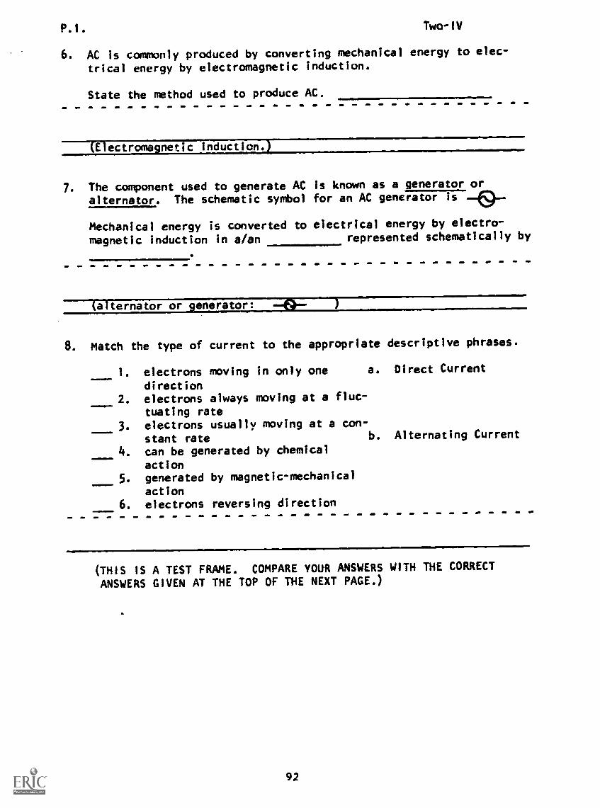
P.I. Two-IV
6. AC is commonly produced by converting mechanical energy to elec-
trical energy by electromagnetic induction.
State the method used to produce AC.
(Electromagnetic induction.)
7. The component used to generate ACalternator. The schematic symbol
Mechanical energy is converted tomagnetic Induction in a/an
is known as a generator orfor an AC generator Is Hell)._
electrical energy by electro-represented schematically by
(alternator or -enerator:
8. Match the type of current to the appropriate descriptive phrases.
mrimEmt
.11=11war
1. electrons moving in only one a. Direct Current
direction2. electrons always moving at a fluc-
tuating rate
3. electrons usually moving at a con-
stant rate b. Alternating Current
4. can be generated by chemical
action5. generated by magnetic-mechanical
action6. electrons reversing direction
(THIS IS A TEST FRAME. COMPARE YOUR ANSWERS WITH THE CORRECT
ANSWERS GIVEN AT THE TOP OF THE NEXT PAGE.)
92
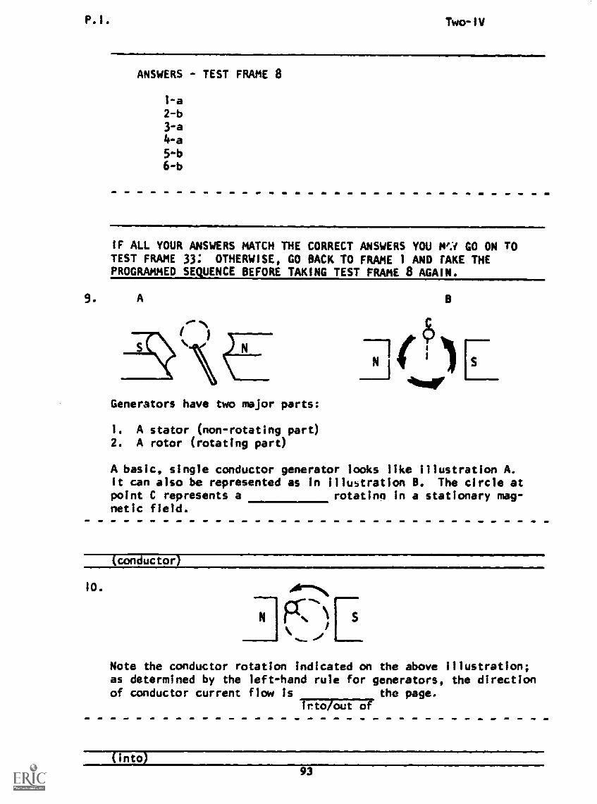
P.I. Two-IV
ANSWERS - TEST FRAME 8
1-a
2-b3-a
4-a
5-b6-b
IMIIMMMINIM=M11111M,
IF ALL YOUR ANSWERS MATCH THE CORRECT ANSWERS YOU MY GO ON TOTEST FRAME 33: OTHERWISE, GO BACK TO FRAME 1 AND TAKE THEPROGRAMMED SEQUENCE BEFORE TAKING TEST FRAME 8 AGAIN.
A
N
Generators have two major parts:
1. A stator (non-rotating part)2. A rotor (rotating part)
B
A basic, single conductor generator looks like illustration A.it can also be represented as in illustration B. The circle atpoint C represents a rotating in a stationary mag-netic field.
'conductor
1O. .411-"N
Fts.b%\ E
Note the conductor rotation indicated on the above illustration;as determined by the left-hand rule for generators, the directionof conductor current flow is the page.
ITITAUF17
(into)
93

P.I. Two-IV
Starting a graph of voltage vs. conductor position at the pointshown above is standard practice.
At zero degrees, the path of the conductor is parallel withthe lines of force. Lines of force are cut.
being/not being
In the illustration, is there an induced current flowing
in the conductor?
'[not being; No)
By moving to the 30° position, as indicated in the above
figure, the conductor's paltli has become more nearly
to the lines of force.
parallel/perpendicular
(perpendic .lar)

P.I. Two-1V
13. In frame 12, lines of forceare/are not
and an EMF being generated.is/is not
being cut
are; s
60 90 ISO 29-0 360
1. At the 600 position, the path has becomenearly perpendicular to the air force.
2. From the 30° to the 60° position, the induced EMF has
Increased/decreased/remained the same
(1. conductor; 2. Increased)
15.
I aI
/ 0 90 IS 2 0 360% /
44---S
N
At the 90° position, the conductor is traveling perpendicularto the lines of force, and the induced EMF is
maximumthe same/minimum/
(maximum
95

P.I. Two-IV
16. In frame 15, at the 90° position, the current in theconductor is flowing the page.
into/out of
(into)
17. Maximum lines of force are being cut at the degree
position of the conductor.
(90a)
I217'0
1360
Moving to the 1200 position, the conductor is at the samerelative cutting angle as at the 60° position. Induced EMF
at the 120° position compared to that at the 90° position
hasIncreased/decreased/remained the same
(decreased)
19. In the above figure, at the 120° position the conductor iscutting fewer lines of force than at 90° because it is more
nearly to the magnetic. flux.
perpendicular/parallel
----TwFoo)
96

inT art' AMILME Two-1V
20. In which drawing would the greatest amount of EMF be generated?
30
a. b. c.
Continuing to move the conductor in the same direction to the150* position, we find that lines of forceare being cut. more/less/the same
(less)
22. Refer to above drawing. At the 150° position we find that theinduced EMF has
increased/decreased/remained the same
(decreased)
97
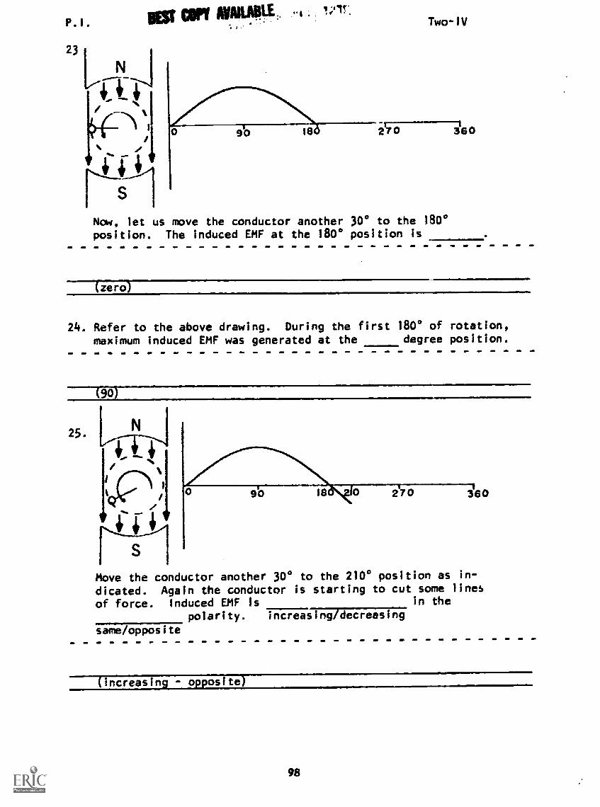
P. I . Mr Ur NAME . 1,11-
Two-IV
Now, let us move the conductor another 30° to the 180°position. The induced EMF at the 180° position is
(zero)
24. Refer to the above drawing. During the first 180° of rotation,maximum induced EMF was generated at the degree position.
25.
t
S
Move the conductor another 30° to the 2100 position as in-
dicated. Again the conductor is starting to cut some linesof force. Induced EMF Is in the
polarity. increasing/decreasing
same/opposite
(increas n . . osite)
98
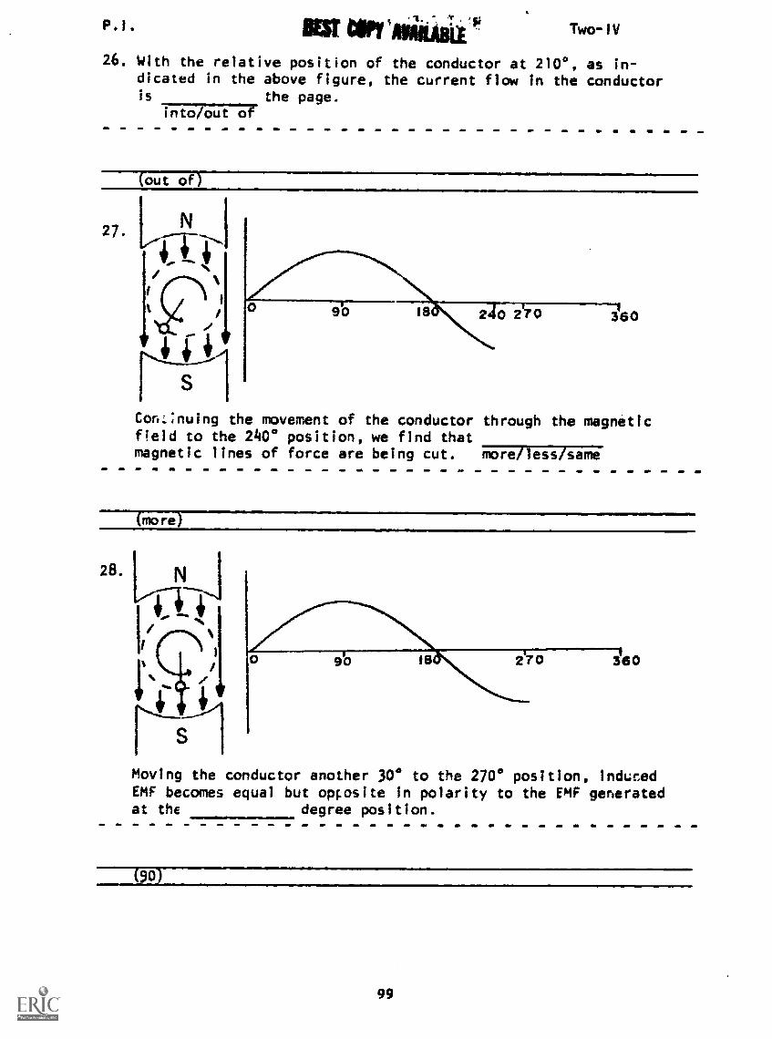
P.1. lakr"ABil Two -IV
26. With the relative position of the conductor at 2100, as in-dicated in the above figure, the current flow in the conductoris the page.
intoTout of
(out off
27.
Con:,:nuing the movement of the conductor through the magneticfield to the 240 position, we find thatmagnetic lines of force are being cut. more/less/same
28.
Moving the conductor another 300 to the 270° position, inducedEMF becomes equal but opposite in polarity to the EMF generatedat the degree position.
(50)
99
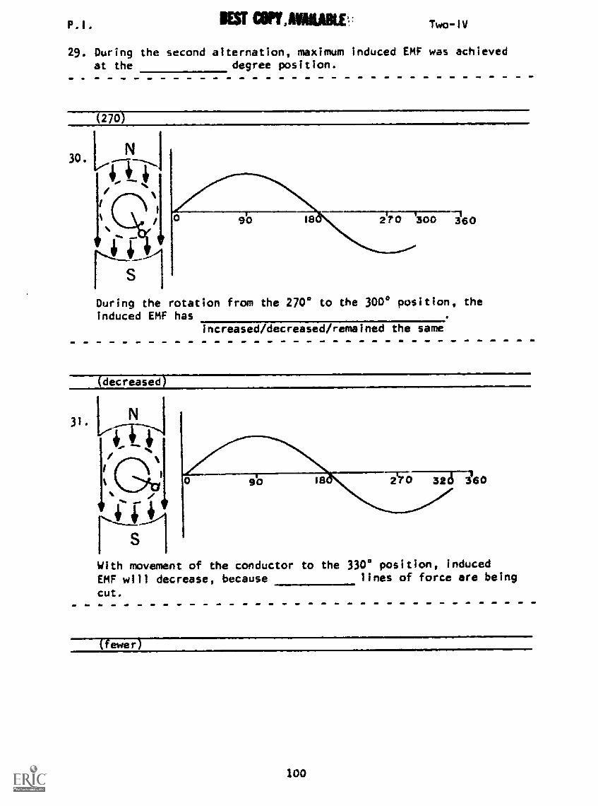
P.1. lEST Two-IV
29. During the second alternation, maximum induced EMF was achievedat the degree position.
(270)
90 18' 2'70 '300 160
During the rotation from the 2700 to the 300° position, theinduced EMF has
Increased/decreased/remained the same
decreased)
31.
, 4--
144.
With movement of the conductor to the 330° position, inducedEMF will decrease, because lines of force are being
cut.
(fewer
100
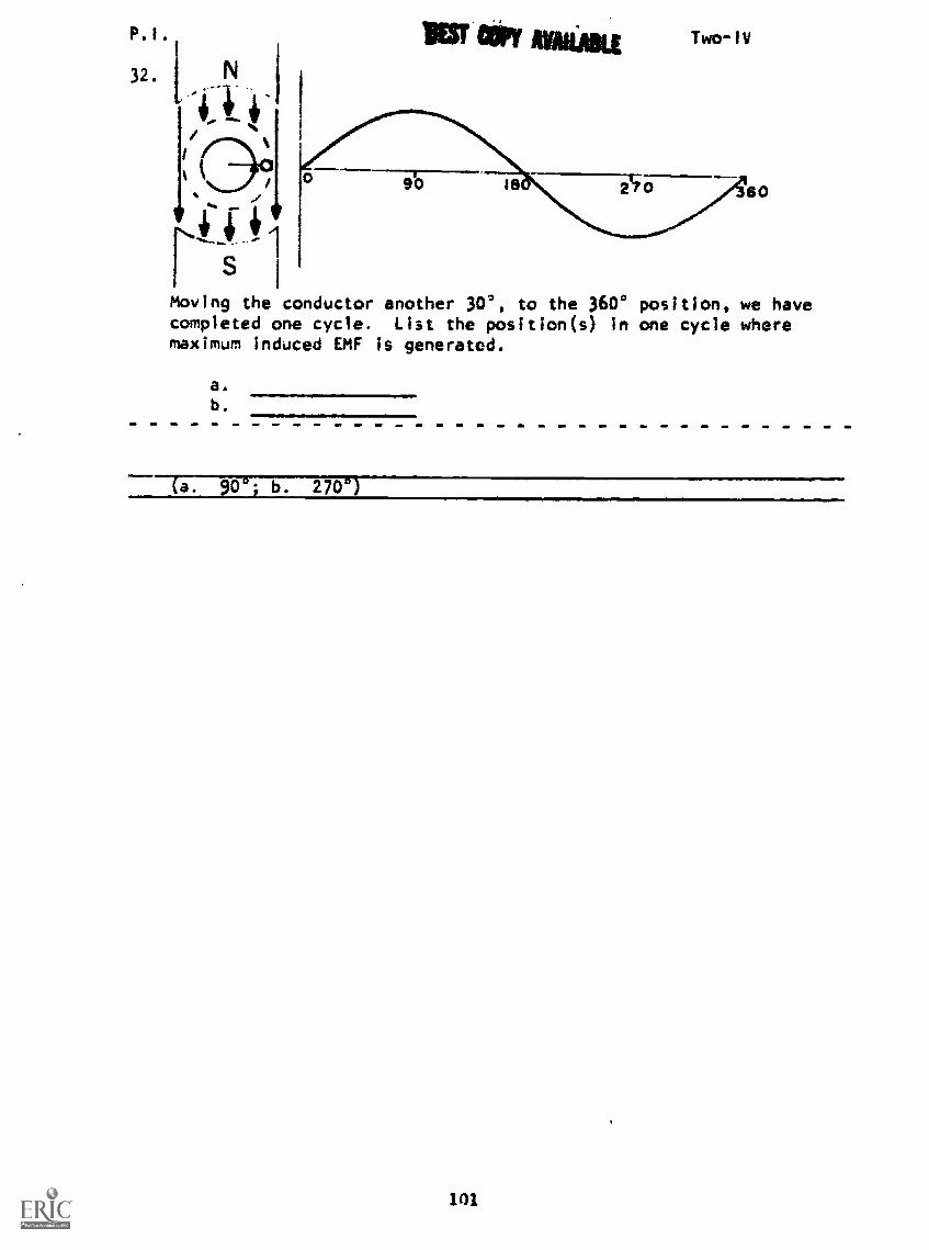
P.1.
32.
t
s
INIST COPY Two-11/
Moving the conductor another 30', to the 3600 position, we havecompleted one cycle. List the position(s) in one cycle wheremaximum induced EMF is generated.
a.
b.
(a. 90"j b. 270')
101
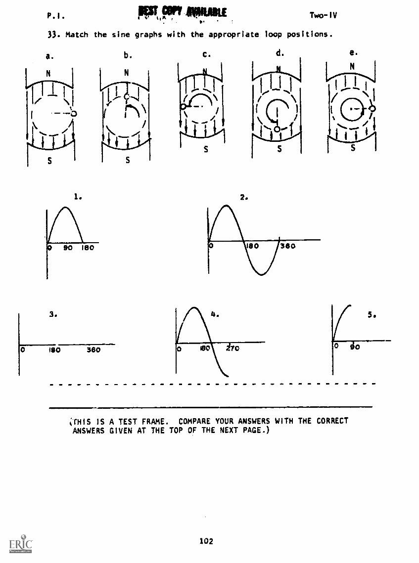
P. I .
33. Match the
a.
S
1.
sine graphs with
b.
N
S
Two-IV
the appropriate loop positions.
c.
2.
d. e.
5.
"THIS IS A TEST FRAME. COMPARE YOUR ANSWERS WITH THE CORRECTANSWERS GIVEN AT THE TOP OF THE NEXT PAGE.)
102

P.I.
34.
IEST COPY NAME Two-IV
ANSWERS - TEST FRAME 33
I. c
2. e
3. a
4. d
5. b
IF ALL YOUR ANSWERS MATCH THE CORRECT ANSWERS, GO ON TO TESTFRAME 62. OTHERWISE, GO BACK TO FRAME 9 AND TAKE THE PROGRAMMEDSEQUENCE BEFORE TAKING TEST FRAME 33 AGAIN.
-al° it, 4 0--31
42 I00,0On the above figure, label the position(s) where maximum in-duced EMF is achieved by placing an X upon your selection.
(4 and 10)
35. Up to this point In the program, we have used a single conductorto demonstrate the development of induced EMF. However, a singleconductor that moves through a magnetic field is not practicalfor producing a usable voltage, because the induced voltage is-too
101,1
103

P.I.
36.
gsfr Ix91 NOBLE Two-IV
The action of a conductor cutting a magnetic field forms thebasis of GENERATOR operation. For example, here's a simpleAC generator consisting of a permanent magnet and a coil ofwire. When the coil the magnetic field, a
is induced in the coil.
(cuts- volts e
37.
A E3
Part A shows just the ends of the permanent magnet. Actually,the magnet is continuous, as in part B.
The permanent magnet provides thein which the coil rotates.
38.
(-magnetic field)
The black side of the coil is moving down through the magneticfiel37The polarity of Si with respect to 52 is positive. Whatis the polarity of 52 with respect to SI? . Current
flows from the white side of the coil, out of S4 through a load
and back in Si.
ne ative
104

pill.
39.BEST CM AMAMI
Two -IV
When the coil is in the position shown, the sides of the coilare moving to the lines of force.
parallel/at right angles
Therefore, voltage is induced in the coil.some 707;
40.
(parallel, zero)
The black side of the coil is moving up through the magneticfield. Current flows from the black side of the loop, out ofS through the load to the whlte side of the loop.
105
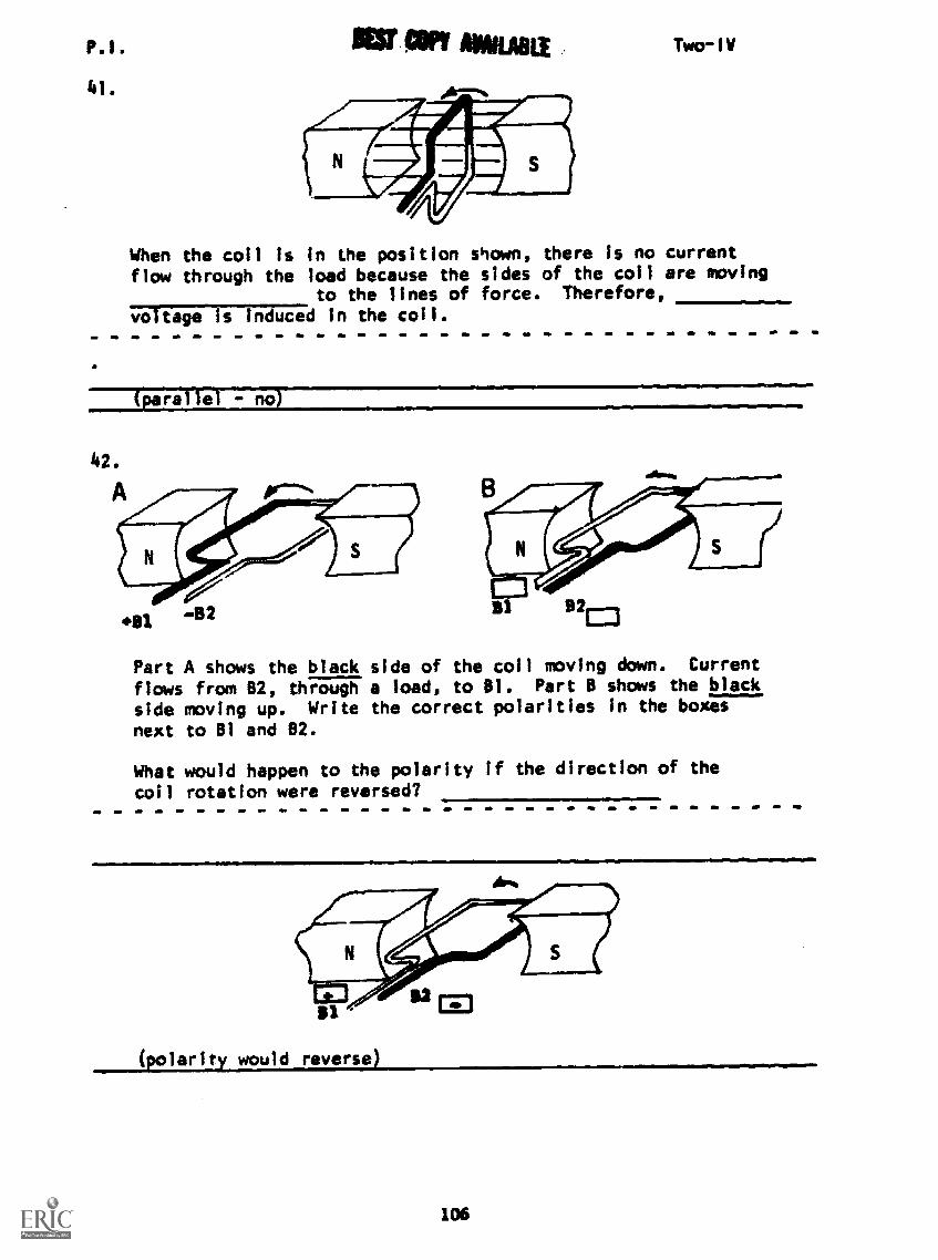
SOB tiff ELIP.I.
41.
Two-1V
When the coil is in the position shown, there is no currentflow through the load because the sides of the coil are moving
to the lines of force. Therefore,
voltage Is incruced in the coil.
441 -B2 a' B2ED
Part A shows the black side of the coil moving down. Current
flows from 82, through a load, to 81. Part B shows the black
side moving up. Write the correct polarities in the boxes
next to 81 and 82.
What would happen to the polarity If the direction of the
coil rotation were reversed?
(polarity would reverse)
106
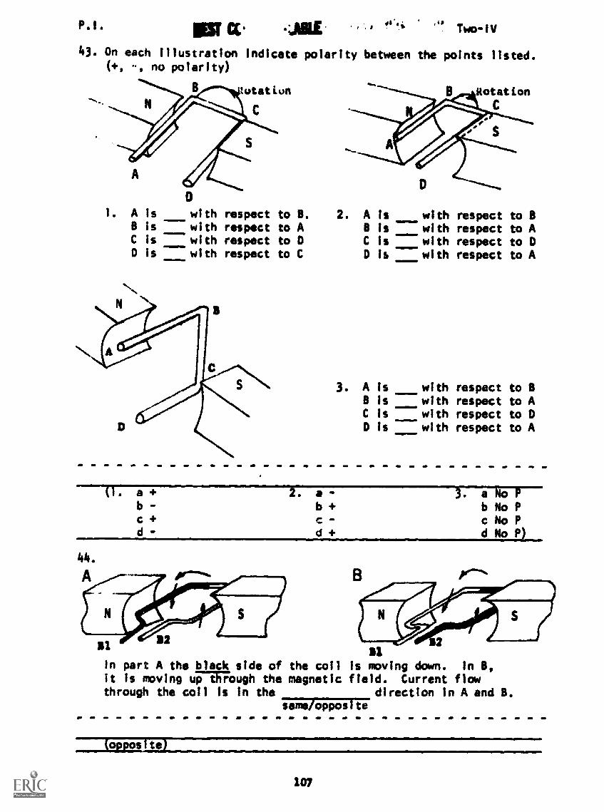
P.1. r . Two-1V
43. On each illustration indicate polarity between the points listed.(+, .., no polarity)
lutatiun
C
A
01. A is with respect to B.
B is with respect to AC is with respect to 0D is with respect to C
2. A is with respect to BB is with respect to AC is with respect to DD is with respect to A
3. A is with respect to BB is with respect to AC is with respect to 0D is with respect to A
(1. a +b
c +d
2. a -b +
-
d +
44.
A
B211
B1In part A the black side of the coil is movingit is moving uTERFOugh the magnetic field. Cuthrough the coil Is in the direct
same Qppos to
3. a 4oPb No Pc No Pd No PI
down. In B,
rrent flowion in A and B.
(opposite)
107
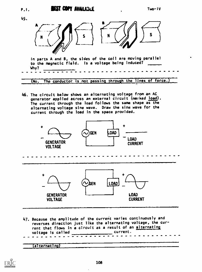
P.1. IN? AVAILLUE
45.
Two-IV
In parts A and B, the sides of the coil are moving parallelto the magnetic field. Is a voltage being Induced?
Why?
No. The conductor is not passim through the lines of force.T
46. The circuit below shows an alternating voltage from an ACgenerator applied across an external circuit (marked load).The current through the load follows the same shape as the
alternating voltage sine wave. Draw the sine wave for thecurrent through the load in the space provided.
GENERATORVOLTAGE
GEN 1.0AD
LOAD
CURRENT
GENERATORVOLTAGE
LOADCURRENT
47. Because the amplitude of thereverses direction just likerent that flows in a circuitvoltage is called
current varies continuously andthe alternating voltage, the cur-as a result of an alternating
current.
a ternat Is
108

P I BEST COPY UNLIKE Two-1V
48. Draw a sine wave of alternating voltage in A below. in part8, draw a sine wave of alternating current. Include polaritiesin your drawings.
AB
AC VOLTAGE AC CURRENT
49. When a coil rotates in a magnetic field, it makes a completecircle called a revolution. A circle consists of 360 degrees.The symbol for degrees is a small circle like this (°). Thus360 degrees is written as 360°. When a coil makes a completecircle, it has gone through one or
One complete revolution is 360°. How many degrees are in1/2 revolution?
(revoli.tior0D- 180-*
109
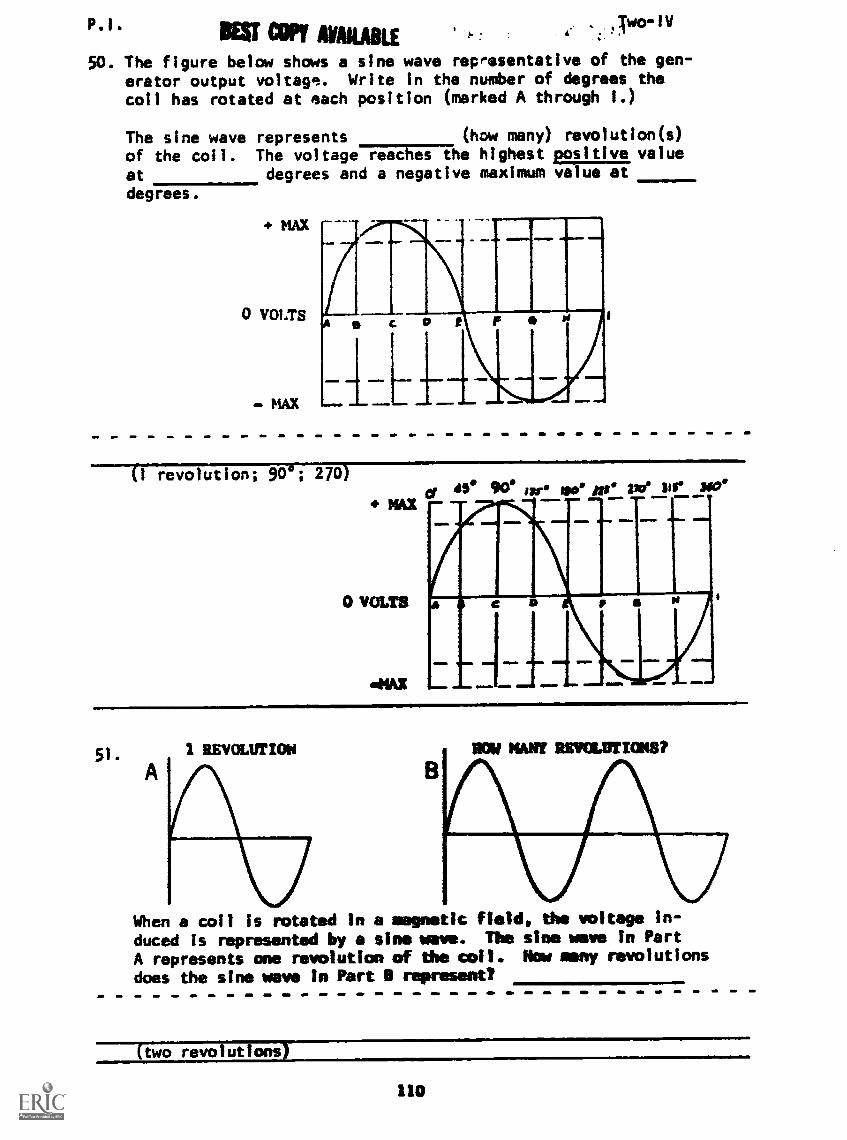
lEff COPY AWAKEtwo -Id
50. The figure below shows a sine wave representative of the gen-erator output voltage. Write in the number of degrees thecoil has rotated at each position (marked A through I.)
The sine wave represents (how many) navolution(s)
of the coil. The voltageTiiagThe highest sitive value
at degrees and a negative maximum va ue atdegrees.
+ MAX
0 VOLTS
MAX
C R p
4,11111
----TT770Ution; 90 °; 270)
0 VOLTS
el 45° 90 isr We Mg alle 'or soce
(=M. MO.
a If
=WM lail/ft 4. 111
51. 1 REVOLUTION NOW NAST REVOLUTIONS?
When a coil is rotated in a magnetic Reidy the voltage in-
duced is represented by a sine wave. The sine wave in Part
A represents one revolution of the coil. Nov many revolutions
does the sine wave In Part 11 represent?
two revolutions)
110
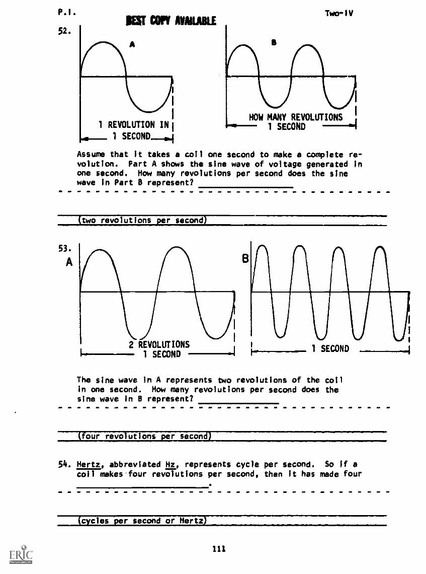
P.1. Two-1VEST Con MARL
52.
1 REVOLUTION IN
1 SECOND---04
HOW MANY REVOLUTIONS ,
1 SECOND
Assume that it takes a coil one second to make a complete re-volution. Part A shows the sine wave of voltage generated inone second. How many revolutions per second does the sinewave in Part B represent?
53-
A
(two _revolutions per second)
2 REVOLUTIONS1 SECOND
B
1 SECOND ________-.4
The sine wave in A represents two revolutions of the coilin one second. How many revolutions per second does thesine wave in B represent?
(four_ revolutions per second)
54. Hertz, abbreviated Hz, represents cycle per second. So If acoil makes four revolutions per second, then it has made four
(cycles per second or Hertz)
111

P.1. Two-IV
55. Another way of saying that a coil makes 10 revolutions in onesecond is that the coil makes 10 per
(cycles per second)
56. If a coil completes five revolutions in one second, how manycycles of voltage has it generated?
(five)
57. How many cycles of voltage does a coil generate when itcompletes 60 revolutions in one second?
(60)
58. The number of complete cycles generated in one second is calledthe frequency of the generator. The word frequency is usedto tell how-frequently the generator produces a voltage cycle.
Frequency is abbreviated f.
So if a coil completes 15 revolutions per second, we say itsis 15 Hertz.
59.
(frequency)
SECOND
B
The frequency of the sine wave in Part A IsWhat is the frequency of the sine wave in Part B?
a Hertz; 4 Hertz
112

P. 1. 11M r*OPY 2f4.414i 1.7 Two-IV
60. A co;1 completes 30 revolutions in one second. If the speed ofthe coil is doubled, what is the frequency generated?
(60 Hertz)
61. The number of cycles completed in one second is called
(frequency)
62.A
1 SECOND
AV AWA WAWAMOND
Referring to the above figures, what Is the frequency in eachcase?
a.
b.
c.
d.
(THIS IS A TEST FRAME. COMPARE YOUR ANSWERS WITH THE CORRECTANSWERS GIVEN AT THE TOP OF THE NEXT PAGE.)
113
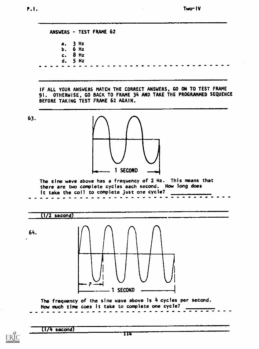
P.I. Twarld
63.
ANSWERS TEST FRAME 62
a. 3 Hzb. 6 Hzc. 8 Hzd. 5 Hz
IF ALL YOUR ANSWERS MATCH THE CORRECT ANSWERS, GO ON TO TEST FRAME91. OTHERWISE, GO BACK TO FRAME 34 AND TAKE THE PROGRAMMED SEQUENCEBEFORE TAKING TEST FRAME 62 AGAIN.
The sine wave above has a frequency of 2 Hz. This means thatthere are two complete cycles each second. How long does
it take the coil to complete Just one cycle?
---117117c7nd
64.
The frequency of the sine wave above is 4 cycles per second.How much time does It take to complete one cycle?
(114 second)114

P.I. Two-IV
65. The time the coil takes to complete one cycle is called theperiod. What is the period of the sine wave shown below"
r.--PERIOD
1 SECOND -eam.alil
(112 second)
66. The frequency of a sine wave is given in Hertz. The time ofone cycle is called the tiperiod)
67. The sine wave below has a period of 1/2 second. How many cyclesare there in one second? What Is its frequency?
1/2 SECOND -4.4
I SECOND
2Hz)
115

P.I. Two-IV
68. The difference between frequency and period i. that frequencymeans and period means
(number of cycles per second; the time of one cycle)
69. The sine wave of voltage below indicates that the voltage risesfrom 0 volts to a maximum value of +5 volts and then falls to 0volts again. This rise and fall of voltage in a positive direction
is called the sitive alternation of the sine wave. By the sametoken, the rise and all7707iie in a negative direction is calledthe
5 VOLTS
0 VOLTS
5 VOLTS
POSITIVEALTEIMATICI4
(negative alternation) 11mMIIMmi=leMmana
70. Here's the sine wave of voltage again. How many degrees of ro-tation does the coil go through in the positive alternation?How many degrees are there in the negative alternation?How many alternations are there Jr one cycle?
4. S VOLTS
0 VOLTS
5 VOLTS
(1800; 180'; 2)
116
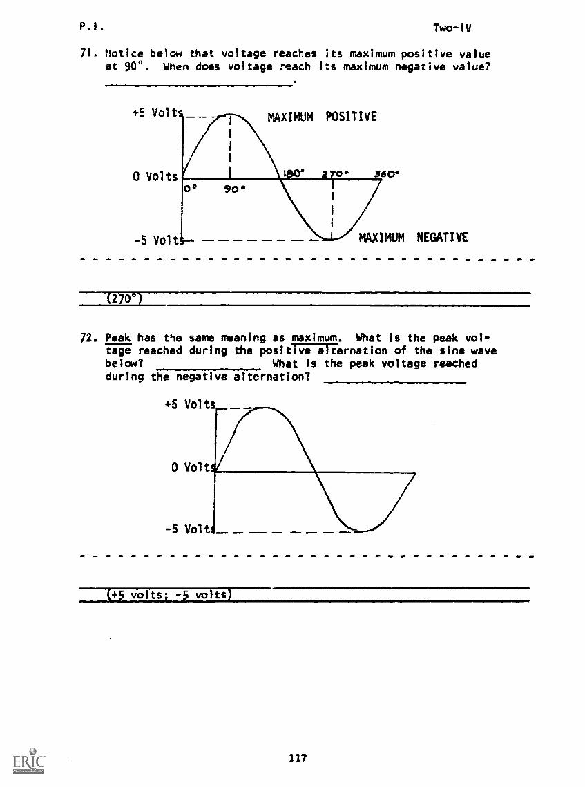
P.1. Two-1V
71. Notice below that voltage reaches its maximum positive valueat 90'. When does voltage reach its maximum negative value?
+5 Volt
0 Volts
-5 Volt
MAXIMUM POSITIVE
TO 560
MAXIMUM NEGATIVE
00 90
IMMO .1 11
72. Peak has the same meaning as maximum. What is the peak vol-tage reached during the positive of the sine wavebelow? What is the peak voltage reachedduring the negative alternation?
(+5 volts; -5 volts)
117

P.I. Two-IV
73. The peak voltage of the positive alternation of the sine wavebelow is volts. What is the peak voltage of thenegative inzizrwir--
+25 Volts
0 Volts
-25 Volts
74. In a sine wave, the positive peak value and the negative peakvalue are always
alike/different
75. In the sine wave below, what is the total voltage between thepositive peak and the negative peak. (Disregard the polarities.)
+100 Volts
0 Volts
-100 Volts !MI=.M...=.
($00 vats)(Prom +100 to 0 equals 100 volts and 0 to -100 equals ibo volts. Thus,the total Is 200 volts.)
118
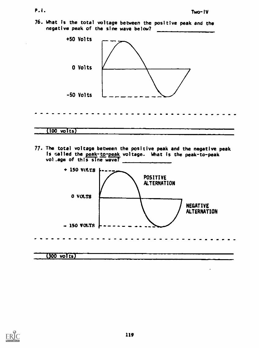
P.I. Two-IV
76. What is the total voltage between the positive peak and thenegative peak of the sine wave below?
+50 Volts
0 Volts
-50 Volts
100 volts
77. The total voltage between the positive peak and the negative peakis called the palkto-pgak voltage. What is the peak-to-peakvoltage of thisiiThe aver
150 VOLTS
0 VOLTS
150 VOLTS
POSITIVEALTERNATION
NEGATIVEALTERNATION
(300 vol ts)
119
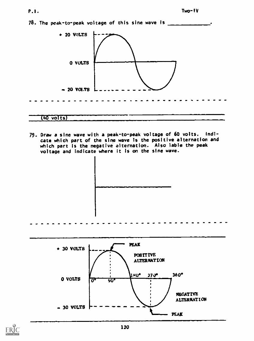
P.1. Two-1V
78. The peak-to-peak voltage of this sine wave is
20 VOLTS
0 VOLTS
20 VOLTS
(0 volts)
79. Draw a sine wave with a peak-to-peak voltage of 60 volts. Indi-
cate which part of the sine wave is the positive alternation and
which part is the negative alternation. Also fable the peakvoltage and indicate where it is on the sine wave.
30 VOLTS
0 VOLTS
- 30 VOLTS
NEGATIVEALTERNATION
120
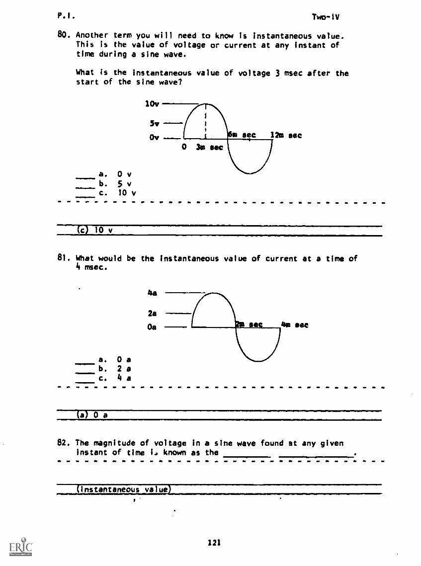
P.I. Two-IV
80. Another term you will need to know is instantaneous value.This is the value of voltage or current at any instant oftime during a sine wave.
What is the instantaneous value of voltage 3 msec after thestart of the sine wave?
10v
5v
Ov
a. 0 vb. 5 vc. 10 v
(c) 10 v
81. What would be the instantaneous value of current at a time of4 msec.
Imariaamom
.1ftIloWlm
a. 0 ab. 2 ac. 4 a
4a
2a
Oa as sac
82. The magnitude of voltage in a sine wave found at any givenInstant of time I. known as the
(instantaneous value
121
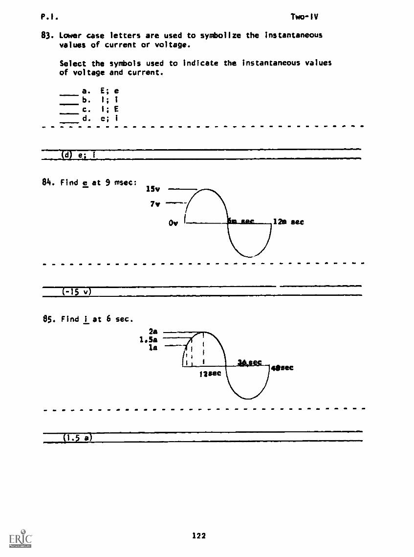
P.I. Two-1V
83. Lower case letters are used to symbolize the instantaneousvalues of current or voltage.
Select the symbols used to indicate the instantaneous valuesof voltage and current.
a. E; eb. 1; 1
c. 1; E
d. e; i
84. Find e at 9 msec:
1254sec
(-15 v)
85. Find 1 at 6 sec.
2a1.5a
la
(1.5 a)
122

13.1. Two-1V
86. Now you'll apply what you've learned to some practical examples.The lamps in the circuits below require 5 amperes of current tolight brightly. Circuit A is a DC circuit in which a constantcurrent of 5 amps flows. Circuit 8 is an AC circuit in whichthe peak current is 5 amps. In which circuit does the lamp lightbrighter? Why?
A
BATTLRY
B
AC (NM 11ATC11
(Circuit A because the 3 amps DC is constant.)
87. To determine the worth or to tell how effective an alternatingcurrent or voltage is, we compare the effect of the AC againstthe effect of DC. Nearly all AC meters are calibrated in ef-fectrAriMues so that the values in AC will be consistent withthe values in DC circuits. For example, if an alternating cur-rent produces as much heat as 1 amp of direct current, then, wesay that the AC Is as as 1 amp DC.
(effective)
88. The effective value, also called MIS value, of an AC voltageor arilWIFTWFriame heating effect as an equal value ofdirect current. So if a peak current of 7 amps AC producesthe same heating effect as 5 amps DC, then 5 amps is the
value of 7 amps AC (peak value).
(effective)
89. A peak AC voltage of 100 volts produces the same heating effectin a load as 70 volts DC. Therefore, the value ofthe AC voltage is volts.
(effective; 70 voits)
123

P.1. Two-1V
90. For a sine wave, the ROOT MEAN SQUARE (RMS) or EFFECTIVE
VALUE is 0.707times the peak value.
The RMS value is computed as the square root of the averageof the squares of the instantaneous amplitudes for onecomplete cycle.
Let's look at the effective (RMS) value of a sine wavewhich has a peak value of 100 V.
Min --EFFECT IVE VALUE 70v - . .11=4=1=,
(70.7% of peak)
Select the lettered arrow which shows the effective value
of voltage.
(b)
124
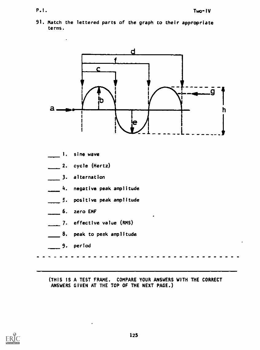
P.I. Two-IV
91. Match the lettered parts of the graph to their appropriateterms.
..11
1. sine wave
2. cycle (Hertz)
3. alternation
4. negative peak amplitude
5. positive peak amplitude
6. zero EMF
7. effective value (RMS)
8. peak to peek amplitude
9. period
(THIS IS A TEST FRAME. COMPARE YOUR ANSWERS WITH THE CORRECTANSWERS GIVEN AT THE TOP OF THE NEXT PAGE.)
125

ANSWERS - TEST FRAME 91
1. d
2. f
3.
4. e5. b
6. a
7. g8. h
9. f
IF ANY OF YOUR ANSWERS IS INCORRECT, GO BACK TO FRAME 63 AND TAKETHE PROGRAMMED SEQUENCE.
IF YOUR ANSWERS ARE CORRECT, YOU MAY TAKE THE PROGRESS CHECK, ORYOU MAY STUDY ANY OF THE OTHER RESOURCES LISTED. IF YOU TAKETHE PROGRESS CHECK AND ANSWER ALL THE QUESTIONS CORRECTLY, GO ONTO THE NEXT LESSON. IF NOT, STUDY ANY METHOD OF INSTRUCTION YOUWISH UNTIL YOU CAN ANSWER ALL THE QUESTIONS CORRECTLY.
126
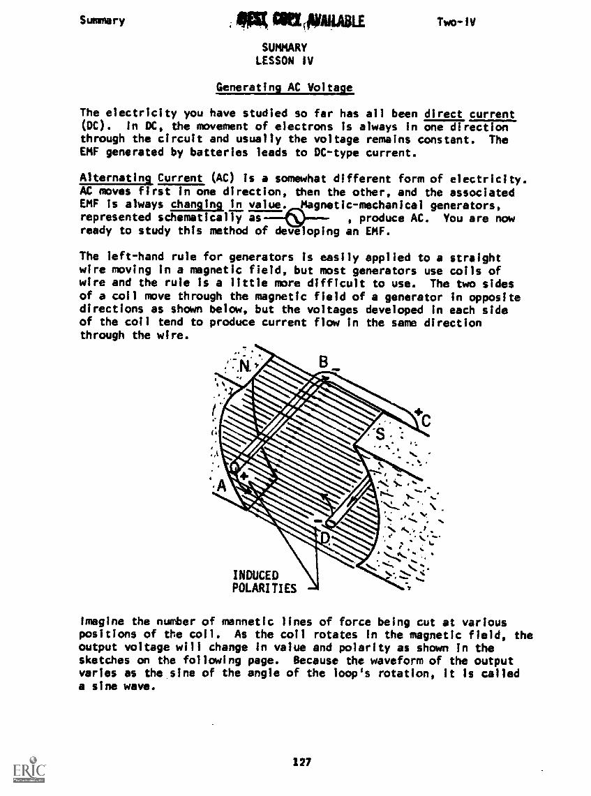
Summary WripAILABLE
SUMMARYLESSON IV
Two-IV
Generating AC Voltage
The electricity you have studied so far has all been direct current(DC). In DC, the movement of electrons is always in one directionthrough the circuit and usually the voltage remains constant. TheEMF generated by batteries leads to DC-type current.
Alternating Current (AC) is a somewhat different form of electricity.AC moves first in one direction, then the other, and the associatedEMF is always changing in value. Magnetic-mechanical generators,represented schematically as----- , produce AC. You are nowready to study this method of developing an EMF.
The left-hand rule for generators Is easily applied to a straightwire moving in a magnetic field, but most generators use coils ofwire and the rule is a little more difficult to use. The two sidesof a coil move through the magnetic field of a generator in oppositedirections as shown below, but the voltages developed in each sideof the coil tend to produce current flow in the same directionthrough the wire.
".
I
INDUCEDPOLARITIES
Imagine the number of mannetic lines of force being cut at variouspositions of the coil. As the coil rotates In the magnetic field, theoutput voltage will change in value and polarity as shown in thesketches on the following page. Because the waveform of the outputvaries as the sine of the angle of the loop's rotation, it is calleda sine wave.
127
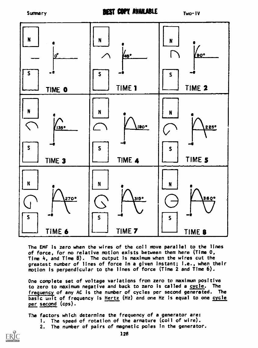
Summary NEST Ulf NAME Two-IV
NN I eN
.
cf H2
S -41
TIME 0
S
. TIME 1
S
...______, TIME.
Ilie
r..
N N
i
1 225°
Se
TIME 3
S
,
e .
TIME 4
1 S
, TIME 5
[ N 1 N
.
N
270° 315° 3
,
S
TIME 6 TIME 7
S
TIME- 8
The EMF is zero when the wires of the coil move parallel to the linesof force, for no relative motion exists between them here (Time 0,Time 4, and Time 8). The output is maximum when the wires cut thegreatest number of lines of force in a given instant; i.e., when theirmotion is perpendicular to the lines of force (Time 2 and Time 6).
One complete set of voltage variations from zero to maximum positiveto zero to maximum negative and back to zero is called a cycle. The
frequency of any AC is the number of cycles per second generated. Thebasic unit of frequency is Hertz (Hz) and one Hz Is equal to one cycleE.e.z. second (cps).
The factors which determine the frequency of a generator are:1. The speed of rotation of the armature (coil of wire).2. The number of pairs of magnetic poles in the generator.
128

1009080706050403020100
Summary Two -IV
Increasing either of these will increase the frequency of the generatedAC.
Sone other characteristics of a sine wave will be important to you inyour study and work with electricity. Amplitude or the value of thewaveform at any instant is one of these quantities. The value of awaveform at any instant of time is known as the instantaneous valueof voltage or current and is symbolized by lower case letter forvoltage (e) and current (i). The maximum or peak value of a sinewave (either positive or negative) is the greatest voltage (or current)
present during a cycle, and thepeak -to -peak, voltage is the algebraicdifference of the positive and
70.7% EFFECTIVE negative peak values. You willPEAK p probably use the effective (or RMS)
TO value more often tan any
PEAK for it is directly comparable toDC values. Ten volts of DC and10 volts of effective AC can do thesame amount Trt1;717Nearly allAC meters are calibrated in effectivevalues, and any AC quantity whichIs stated without specifying thetype of value is given in effectivevalues.
This sketch of a sine wave may clarify the values for you.
AT THIS POINT, YOU MAY TAKE THE LESSON PROGRESS CHECK, OR YOU MAYSTUDY THE LESSON NARRATIVE OR THE PROGRAMMED INSTRUCTION OR BOTH.IF YOU TAKE THE PROGRESS CHECK AND ANSWER ALL OF THE QUESTIONS COR-RECTLY, GO TO THE NEXT LESSON. IF NOT, STUDY ANOTHER METHOD OFINSTRUCTION UNTIL YOU CAN ANSWER ALL THE QUESTIONS CORRECTLY.
129/!3p

BASIC ELECTRICITY AND ELECTRONICS
INDIVIDUALIZED LEARNING SYSTEM
MODULE TWO
LESSON V
Uses of AC and DC
Study Booklet
131
Overview Two-V
OVERVIEW
LESSON V
Uses of AC and DC
In this lesson you will study and learn about the following:
- AC generators
- uses of AC and DC
Each of the above topics will be discussed in the order listed.
As you proceed through this lesson, observe and follow directions
carefully.
BEFORE YOU START THIS LESSON, PREVIEW THE LIST OF STUDY RESOURCES
ON THE NEXT PAGE.
132

Study Resources Two-V
LIST OF STUDY RESOURCES
LESSON V
Uses of AC and DC
To learn the material in this lesson, you have the option of
choosing, according to your experience and your preferences, any or
all the of the following:
STUDY BOOKLET:
Lesson Narrative
Programmed Instruction
Lesson Summary
ENRICHMENT MATERIAL:
NAVPERS 93400A-la "Basic Electricity, Direct Current."
Fundamentals of Electronics. Bureau of Naval Personnel.
Washington, D.C.: U. S. Government Printing Office, 1965.
NAVPERS 93400A-lb "Basic Electricity, Alternating Current."
Fundamentals of Electronics. Bureau of Naval Personnel.
Washington, D.C.: U. S. Government Printing Office, 1965.
NAVPERS 10086-A "Basic Electricity." Chapter 8.
Fundamentals of Electronics. Bureau of Naval Personnel.
Washington, D.C.: U. S. Government Printing Office, 1965.
AUDIO-VISUAL:
Sound/Slide - "AC 6 DC Generators"
Remember, you may study all or any of these that you feel are necessary
to answer all Progress Check questions correctly. Do not forget, that
in one sense of the word, your instructor is a living resource, perhaps
the best. Call him if you have any kind of a problem.
YOU MAY NOW STUDY AMY OR ALL OF THE RESOURCES LISTED ABOVE. YOU MAY
TAKE THE PROGRESS CHELK AT ANY TIME.
133
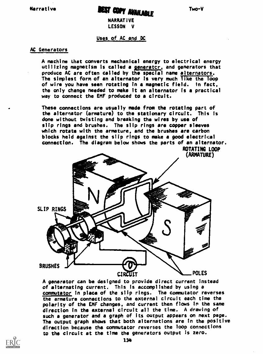
Narrative Ifg' copy mowNARRATIVELESSON V
Uses of AC and DC
Two-V
AC Generators
A machine that converts mechanical energy to electrical energyutilizing magnetism is called a generatcr, and generators thatproduce AC are often called by the special name alternators.The simplest form of an alternator is very much Pike the loopof wire you have seen rotating in a magnetic field. In fact,
the only change needed to make it an alternator is a practicalway to connect the EMF produced to a circuit.
These connections are usually made from the rotating part ofthe alternator (armature) to the stationary circuit. This isdone without twisting and breaking the wires by use ofslip rings and brushes. The slip rings are copper sleeveswhich rotate with the armature, and the brushes are carbonblocks held against the slip rings to make a good electricalconnection. The diagram below shows the parts of an alternator.
ROTATING LOOP(ARMATURE)
SLIP RINGS
BRUSHES
CI POLES
A generator can be designed to provide direct current insteadof alternating current. This is accomplished by using acommutator in place of the slip rings. The commutator reversesthe armature connections to the external circuit each time thepolarity of the DIE changes, and current then flows in the samedirection in the external circuit all the time. A drawing ofsuch a generator and a graph of its output appears on next page.The output graph shows that both alternations are in the positivedirection because the commutator reverses the loop connectionsVD the circuit at the time the generators output Is zero.
134

NarrativeCOFT Two-V
For a better understanding of both alternators and DC generators,examine the CROW models available from the resources center.
Uses of AC and DC
You probably wonder now why you should have to learn about twodifferent kinds of current flow. The answer Is that both kindsare used very widely. You are probably most familiar with ACfor it Is commonly used to supply homes and ships. it is widelyused because it can be transmitted over long distances moreeconomically than DC and it is more efficient for driving motors,
DC is used when voltage fluctuations and direction changescause trouble. Many circuits in radios, television sets,phonographs, and instruments which use amplifiers will not workproperly on AC. You know that your house current is AC and yourradio and TV operate when they are plugged into your housecurrent. How can these things be true? The secret Is thatboth the radio and TV have power supplies which convert theAC from the wall socket into DC for use inside the set.
You have finally found out what your power supply does; allwe have to do now is find out how it does it.
AT THIS POINT, YOU MAY TAKE THE PROGRESS CHECK, OR YOU MAY STUDY ANYOF THE OTHER RESOURCES LISTED. IF YOU TAKE THE PROGRESS CHECK ANDANSWER ALL OF THE QUESTIONS CORRECTLY, GO TO THE NEXT LESSON. IF NOT,STUDY ANY METHOD OF INSTRUCTION YOU WISH UNTIL YOU CAN ANSWER ALL THEQUESTIONS CORRECTLY.
135

PROGRAMMED INSTRUCTIONLESSON V
Uses of AC and DC
TEST FRAMES ARE 10 AND 27. AS BEFORE, GO FIRST TO TEST FRAME 10AND SEE IF YOU CAN ANSWER ALL THE QUESTIONS THERE. FOLLOW THE
DIRECTIONS GIVEN AFTER THE TEST FRAME.
1. Recall from the previous lesson that AC is generated by a
2. The generator has two major parts: (1) a stator and (2) the
armature.
The part of the generator which does not move is the:
a. armature.b. stator.
----III) Stator
I
w~.3. The armature in the generator consists of the rotating loop
and its frame.
Select the arrow showing the armature.
a
136
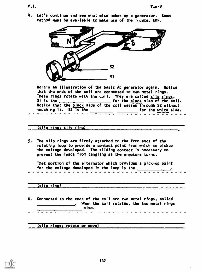
P.1. Two -V
4. Let's continue and see what else makes up a generator. Somemethod must be available to make use of the induced EMF.
Here's an illustration of the basic AC generator again. Noticethat the ends of the coil are connected to two metal rings.These rings rotate with the coll. They are called _slip_ rings.Si is the for the black sidiaa- the coil.Notice that the black sidIVFre coil passes through 52 withouttouching it. S2 is the for the white side.
(slip ring; slip ring)
5. The slip rings are firmly attached to the free ends of therotating loop to provide a contact point from which to pickupthe voltage developed. The sliding contact is necessary toprevent the leads from tangling as the armature turns.
That portion of the alternator which provides a pick-up pointfor the voltage developed in the loop is the
(slip ring)
6. Connected to the ends of the coil are two metal rings, called. When the coil rotates, the two metal rings
also.
(slip rings; rotate or move)
137
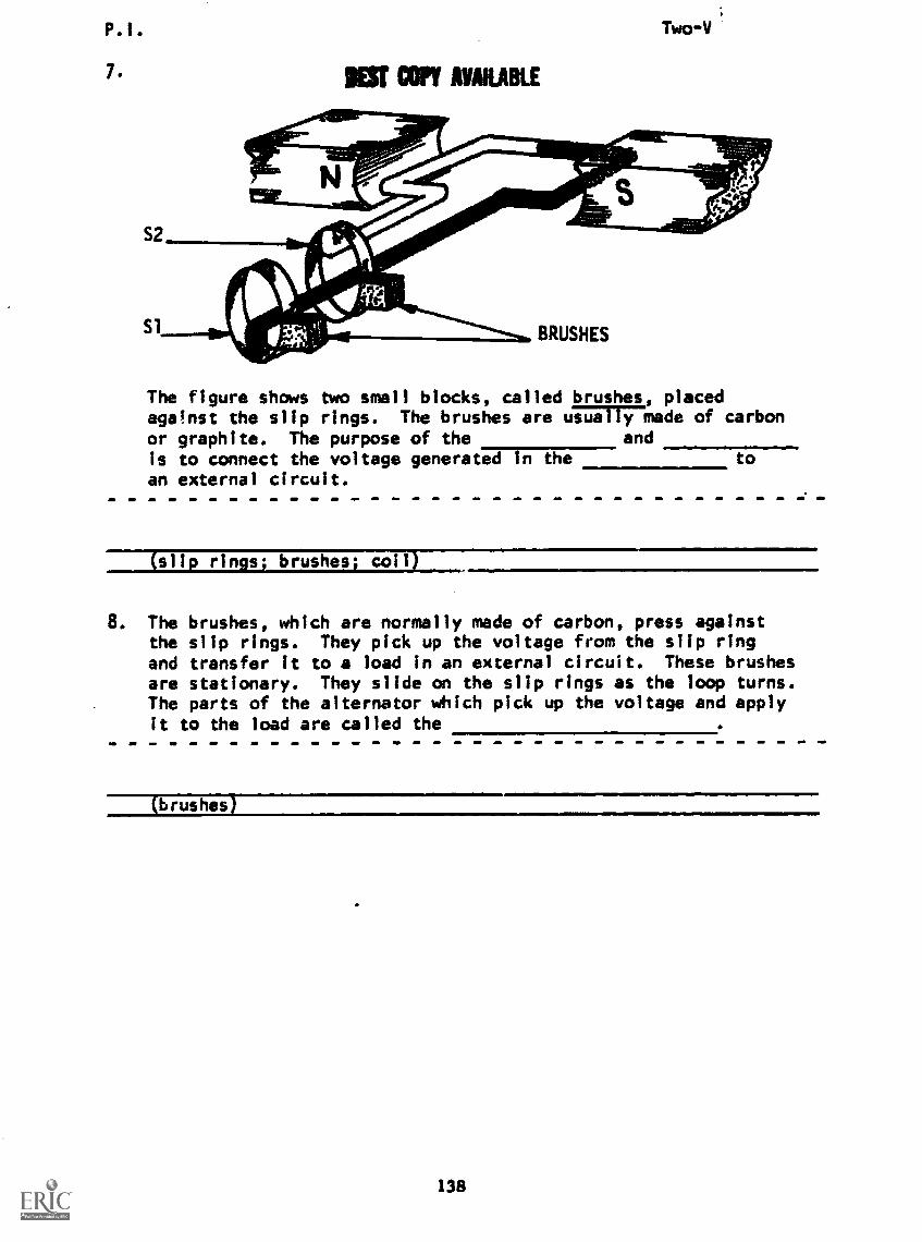
R.I. Two-V
7. MT COPY AVAILABLE
The figure shows two small blocks, called brushes, placedagainst the slip rings. The brushes are arilITYinade of carbonor graphite. The purpose of the andis to connect the voltage generated in thean external circuit.
to
(slip rings; coil
8. The brushes, which are normally made of carbon, press againstthe slip rings. They pick up the voltage from the slip ringand transfer it to a load in an external circuit. These brushesare stationary. They slide on the slip rings as the loop turns.The parts of the alternator which pick up the voltage and applyit to the load are called the
138
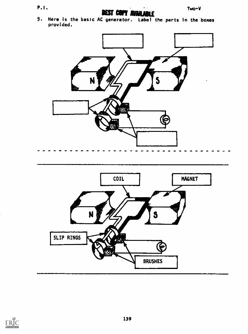
P.'.
KU IMMIE9. Here is the basic AC generator. Label the parts in the boxes
provided.
Two-V
139
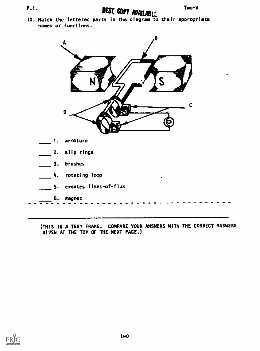
P.1. Two-V
BEST con mama10. Match the lettered parts in the diagram to their appropriate
names or functions.
1. armature
2. slip rings
3. brushes
4. rotating loop
5. creates lines-of-flux
6. magnet
(THIS IS A TEST FRAME. COMPARE YOUR ANSWERS WITH THE CORRECT ANSWERS
GIVEN AT THE TOP OF THE NEXT PAGE.)
140
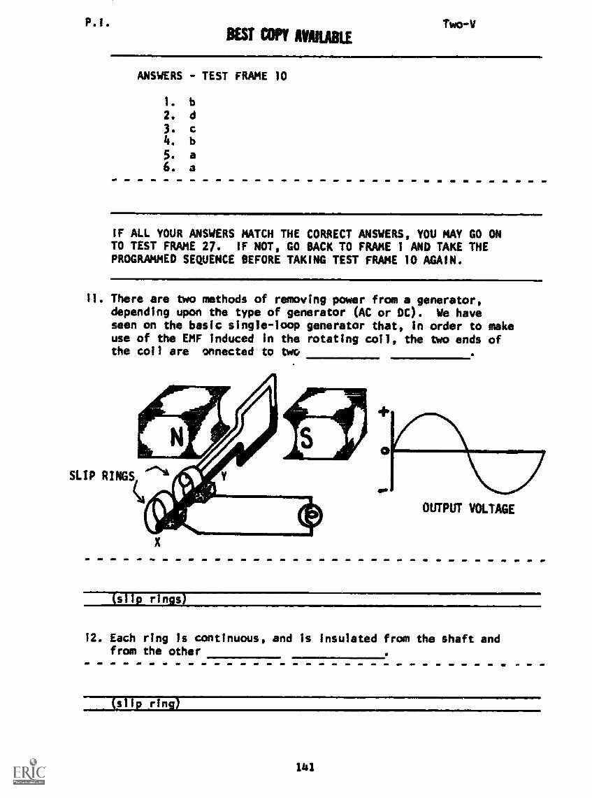
P.I. Two-VBEST CM AVMABLE
ANSWERS - TEST FRAME 10
1. b
2. d
3.
4. b
5. a6. a
IF ALL YOUR ANSWERS MATCH THE CORRECT ANSWERS, YOU MAY GO ONTO TEST FRAME 27. IF NOT, GO BACK TO FRAME 1 AND TAKE THEPROGRAMMED SEQUENCE BEFORE TAKING TEST FRAME 10 AGAIN.
11. There are two methods of removing power from a generator,depending upon the type of generator (AC or DC). We haveseen on the basic single-loop generator that, in order to makeuse of the EMF induced in the rotating coil, the two ends ofthe coil are onnected to two
OUTPUT VOLTAGE
(slip rings)
12. Each ring is continuous, and is insulated from the shaft andfrom the other
(slip ring)
141
P.1. Two-V
13. The two carbon brushes (X and Y in the figure, frame 11)which are connected to the load (lamp) rest on the
(slip rings)
14. As the coil is rotated, the brushes make sliding contactwith the completing the circuit at
all times.
(slip rings)
15. Alternating current is described as current which periodicallyreverses direction. The EMF induced in a rotating coil isalternating, and through the use of slip rings, the outputvoltage Is also
(alternating)
16. An AC voltage is taken from an AC generator by the use ofand
----1;11p rings and brushes)
17. Slip rings are used in generators.
(AC)
142

P.I. I COP1 MIAMI Two -V
18. Since the EMF induced in any rotating coil is alternating,slip rings cannot be used in a DC generator to conduct directcurrent from the coil to the external load. Instead, one splitring (or commutator) is substituted for the two slip rings.As shown T7677Tiure below, each half of the split ring is
# temporarily making contact with one side of the generator coil.As shown brush X is positive with respect to brush Y.
DIRECTION OFROTATION
INSULATINGMATERIAL
OUTPUTVOLTAGE
BASIC DC GENERATOR
As the armature turns so that brush X is wiping the commutatorsection attached to the white side of the armature, what is thepolarity of brush X to brush Y?
(positive)
19. As you can see, as the armature rotates, brush X shifts fromone side of the armature to the other side. This shift causes
the output voltage to be of constant and the
shift is accomplished by use of a
(polarityi commutator)
143

R.I. Two -V
20. A is used tc keep the outside circuitcurrent flowing continually in the same direction in a DCgenerator.
(commutator)
21. Both AC and DC generators produce alternating current Intheir armature coils. By using a commutator, the output ofa generator is a voltage.ACTDC AC/DC
(DC; DC)
22. As we found earlier in this program, another name for an ACgenerator is alternator. Slip rings are used in an
(alternatorl
23. List the two methods of collecting EMF from a generator,along with the type of generator in which each method is used.(either order)
are used in generators.AUK
are used in generators.AC ATIF
(clommutators - DC; slip rings - AC)
24. As you recall, direct current flows in one direction only. Thetype of current which reverses direction periodically is calledalternating current.
Alternating current can be de.ifribed as:
a. current which flows !mono direction only.b. current which flows in both directions at once.c. current which periodically reverses direction.
d. current which never changes direction.
(c) current which periodically reverses direction
144

PI. Two-V
25. Why go to all the trouble of having AC and DC? AC is usuallyused to transmit energy over great distances because thelosses are low. Low voltage DC transmission is more likelyto be used for:
a. long distances.b. short distances.
(b) short distances
26. AC voltages can also be increased or decreased in magnitudewith very little loss. This is done in your power supply bythe transformer.
State the purpose of your power supply transformer.
(To increase or decrease the voltage)
27. Write, as appropriate, AC or DC in the space provided.
slIMMINIMINEMIMa. Usually used for transmission over great distances
with low loss of energy.
b. The output generated does not vary in directionand magnitude.
c. Generator has its contact ring divided into segments(commutator) .
d. Generator has slip rings which transmit EMF tothe load.
e. Voltage may be increased or decreased in valuewith a low loss of energy.
(THIS IS A TEST FRAME. COMPARE YOUR ANSWERS WITH THE CORRECT
ANSWERS GIVEN AT THE TOP OF THE NEXT PAGE.)
145
P.I. Two-V
ANSWERS - TEST FRAME 27
a. AC
b. DC
c. DC
d. AC
e. AC
IF ALL YOUR ANSWERS MATCH THE CORRECT ANSWERS, YOU MAY GO ONTO FRAME 28. IF NOT, GO BACK TO FRAME 11 AND TAKE THE PROGRAMMEDSEQUENCE BEFORE TAKING TEST FRAME 27 AGAIN.
28. The use of DC is limited, especially around the home. Aboutthe only place it is found is in a radio or television. But
are not both the radio and television plugged Into the ACoutlets? They sure are! So how do they get DC power from anAC line? Very simple. Remember your power supply? Insideyour radio and television are power supplies very similar tothe one you built. They contain especially designed circuitsthat convert AC into DC. The DC is then supplied for the circuitsrequiring it.
Power supplies convert to
(AC to DC
29. The primary purpose of the power supply is to:1 a. step up voltage.b. convert AC to DC.c. step down current flow.
(b) convert AC to DC!TOTE: File It is true that voltages may be stepped up
power supply, this is not the primary purpose.)
IF YOU FEEL YOU UNDERSTAND THIS MATERIAL, YOU MAY TAKE THE PROGRESS
CHECK, OR YOU MAY STUDY ANY OF THE OTHER RESOURCES LISTED. IF YOU
TAKE THE PROGRESS CHECK AND ANSWER 4LL THE QUESTIONS CORRECTLY, GO
ON TO THE NEXT LESSON. IF NOT, STUDY ANY METHOD OF INSTRUCTION YOU
WISH UNTIL YOU CAN ANSWER ALL THE QUESTIONS CORRECTLY.
141

SUMMARYLESSON V
Uses of AC and DC
An AC generator is usually called an alternator, indicating that itsoutput is alternating current. The simple machine which producedthe sine wave in the last lesson needs only a method for connectingits output to a circuit without twisting and breaking the wires tobe an alternator. This is done by the use of brushes and slip ringsas shown here:
SLIP RINGS
BRUSHES CIRCUITPOLES
The brushes are made of a soft material, often carbon, and slideagainst the rotating slip rings to make the electrical connectionfrom the alternator to the lamp. A variation of the slip ringscan be used to change the generated AC to DC. This device(commutator) keeps one brush connected to the positive end ofthe loop at all times. A commutator and its output waveforms areshown below. Notice that the brushes are arranged so that the switchis made when the output of the loop is zero.
(See next page)
147
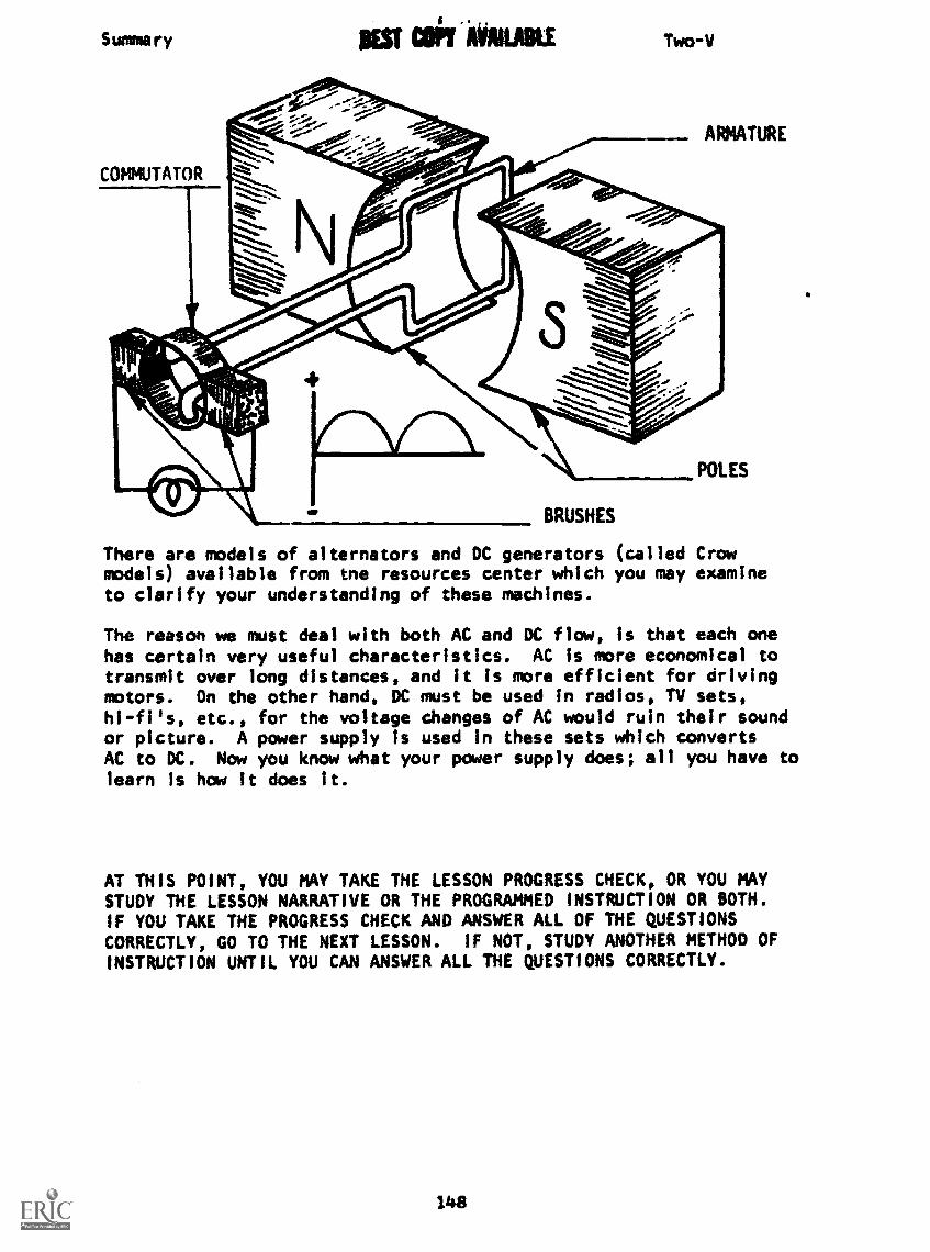
Surma ry 1ST COT AMIABLE Two-V
There are models of alternators and DC generators (called Crowmodels) available from tne resources center which you may examineto clarify your understanding of these machines.
The reason we must deal with both AC and DC flow, is that each onehas certain very useful characteristics. AC is more economical totransmit over long distances, and it is more efficient for drivingmotors. On the other hand, DC must be used in radios, TV sets,hi-fi's, etc., for the voltage changes of AC would ruin their soundor picture. A power supply Is used in these sets which convertsAC to DC. Now you know what your power supply does; all you have tolearn Is how it does it.
AT THIS POINT, YOU MAY TAKE THE LESSON PROGRESS CHECK, OR YOU MAYSTUDY THE LESSON NARRATIVE OR THE PROGRAMMED INSTRUCTION OR BOTH.IF YOU TAKE THE PROGRESS CHECK AND ANSWER ALL OF THE QUESTIONSCORRECTLY, GO TO THE NEXT LESSON. IF NOT, STUDY ANOTHER METHOD OFINSTRUCTION UNTIL YOU CAN ANSWER ALL THE QUESTIONS CORRECTLY.
148
BASIC ELECTRICITY AND ELECTRONICS
INDIVIDUALIZED LEARNING SYSTEM
MODULE TWO
LESSON VI
Measuring Voltage
Study Booklet
149

Overview Two-VI
OVERVIEW
LESSON VI
Measuring Voltage
In this lesson you will study and learn about the following:
-where voltage can be measured
- the voltmeter
- measuring voltage in a circuit
-measuring voltage of cells In series
-measuring voltage of cells in
parallel
-measuring cells connected in series
opposition
-measuring cells connected in series
and in series opposition
Each of the above topics will be discussed in the order listed.
As you proceed through this lesson, observe and follow directions
carefully.
BEFORE YOU START THIS LESSON, PREVIEW THE LIST OF STUDY RESOURCES
ON THE NEXT PAGE.
150
Study Resources Two-VI
LIST OF STUDY RESOURCES
LESSON VI
Measuring Voltage
To learn the material in this lesson, you have the option of choosing,
according to your experience and your preferences, any or all of the
following:
STUDY BOOKLET:
Lesson Narrative
Programmed Instruction
Lesson Summary
ENRICHMENT MATERIAL:
NAVPERS 99400A-la "Basic Electricity, Direct Current."
Fundamentals of Electronics. Bureau of Naval Personnel.
Washington, D.C.: U.S. Government Printing Office, 1965.
AUDIO-VISUAL:
Sound/Slide - "The Voltmeter"
YOU MAY NOW STUDY ANY OR ALL OF THE RESOURCES LISTED ABOVE. YOU
MAY TAKE THE PROGRESS CHECK AT ANY TIME. UPON COMPLETION OF THIS
LESSON YOU SHOULD ASK YOUR INSTRUCTOR FOR THE MODULE TEST COVERING
ALL THE LESSONS IN THIS BOOKLET. YOU MAY REVIEW PREVIOUS LESSONS
IF YOU WISH.
151
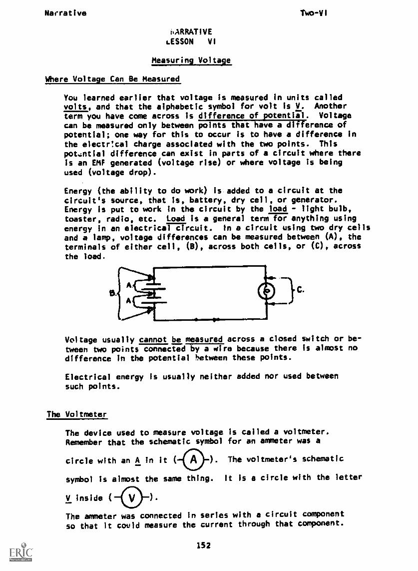
Narrative Two-VI
i.ARRATIVE
LESSON VI
Measuring Voltage
Where Voltage Can Be Measured
You learned earlier that voltage is measured in units calledvolts, and that the alphabetic symbol for volt Is V. Another
term you have come across is difference of potential. Voltagecan be measured only between points that have a difference ofpotential; one way for this to occur is to have a difference inthe electr!cal charge associated with the two points. Thispotential difference can exist in parts of a circuit where thereis an EMF generated (voltage rise) or where voltage is beingused (voltage drop).
Energy (the ability to do work) Is added to a circuit at thecircuit's source, that is, battery, dry cell, or generator.Energy is put to work in the circuit by the load - light bulb,toaster, radio, etc. Load is a general term for anything usingenergy in an electrical in a circuit using two dry cellsand a lamp, voltage differences can be measured between (A), theterminals of either cell, (a), across both cells, or (C), across
the load.
B.
Voltage usually cannot be measured across a closed switch or be-tween two points connected by a wire because there is almost no
difference in the potential between these points.
Electrical energy is usually neither added nor used betweensuch points.
The Voltmeter
The device used to measure voltage is called a voltmeter.Remember that the schematic symbol for an ammeter was a
circle with an A in it ( ). The voltmeter's schematic
symbol is almost the same thing. it is a circle with the letter
V inside ( ) .
The ammeter was connected in series with a circuit component
so that it could measure the current through that component.
152

Narrative Two-VI
Because the voltmeter measures the difference in potentialbetween two points, it is connected between those points, andthe circuit is not opened to make this connection. We saythat the voltmeter is connected in parallel with the componentacross which we want to measure voltage. The diagram belowshows a voltmeter connected across a light bulb to determinethe voltage dropped by the light bulb.
Polarity must be observed in DC circuits; voltmeter probes mustbe inserted in the voltmeter Jacks with red probe in red Jackand black probe in black jack.
When you measure voltage there are several steps in makingthe reading. The method given here is to be used when measur-ing low voltages (30 v or less) only.
1. Hold the probes by the insulated plastic handles only.Gripping any other part of the probe or wire may makeyou part of the circuit - not a comfortable or safe
situation.2. Always be certain the meter can Measure the voltage in
the circuit. If the voltage is too high for the meter,it will damage, possibly destroy, the meter.
3. DC voltmeters are polarity sensitive just like DCammeters. Connecting one in reverse may bend its pointeror jam the meter. Always connect the negative (black
or -) probe to the point nearest the negative side ofthe source and the positive (red or +) probe to thepoint nearest the positive terminal of the source.
4. Read the voltage on the face of the meter.5. Remove probes from the circuit.
Earlier in the module you learned that if cells are connected in
different ways, different voltages will result. Now you can prove
this to yourself by taking act.al measurements.
Measuring Voltage of Cells in Series
1. Get a voltmeter from the resources center.2. Connect three 1-1/2-volt cells in series.
3. Touch the positive meter probe to the positive terminal of
the cell which has no wire connected to it.
4. Touch the negative meter probe to the negative terminal of
the cell which has no wire connected to it.
5. What does the voltmeter Indicate?
You should get an indication of approximately 4-1/2 volts, proving
that voltages of cells connected in series are additive.
153

Narrative
Measuring_ Voltage of Cells in Parallel
Two-VI
1. Connect three 1-1/2-volt cells in parallel as indicated bythe schematic representation. I
T T -r-2. Touch negative meter probe to the negative terminal of
any cell.3. Touch positive meter probe to the positive terminal of
any cell.4. What is the meter indication?
The meter indicates approximately 1-1/2 volts proving that cellsconnected in parallel have the same output voltage as cAe cell.
Measuring Voltage of Cells Connected in Series Opposition
1. Connect two 1-1/2-volt cells in series opposition as theschematic representation indicates.
2. Touch negative probe of meter to the positive terminal ofeither cell.
3. Touch positive probe of meter to the positive terminal of
the other cell.4. What is the meter indication?
The meter indicates 0 volts, proving that when cells are connected'
in series opposition, the voltages are subtractive.
Measurins_Voltagp of Cells Connected in Series Aidingand in Series Opposing
1. Connect two 1-1/2-volt cells in series aiding and a third
1-1/2-volt cell in series opposition to the first two.
2. Touch negative meter probe to terminal b."
3. Touch positive meter probe to terminal a.4. What does the voltmeter indicate?
The meter indication is 1-1/2 wilts. This is explainable
because you connected two cells in series providing 3 volts
between them. Then by connecting another cell In seriesopposition, you have cancelled 1-1/2 volts of the 3 volts.
154

Narrative
Now let's take measurements in a circuit.
Measuring Voltages in a Circuit
Two-VI
Using PB 0-1, two dry cells, and connecting wires, set up acircuit as show by the schematic diagram.
T1
cell #1
--11- cell #2
T8
Using your voltmeter and test leads, measure voltage in thecircuit as follows:
T7
DS1
1. Connect red positive probe to T8. (Touch only red plasticsleeve of the probe.)
2. Connect black negative probe to Ti.3. a. Record voltage between T8 - Tl.
b. Measure and record voltage between Tif tl.
c. Measure the difference in potential between TalEricithe
negative terminal of cell 2.d. What is the voltage between thili;FETve terminal of
cell 2 and T1?e. Close switch.
Read and record voltage between T2 - Ti.Is it a voltage rise or a voltage drop?
f. With switch closed, what is the differenciMForentialbetween T7 - T8?
g. Are the cells in this circuit connected in series orparallel?
Check your answers with those on the next page.
Answers:
Recall that meter readings are approximate because tolerancesmust be considered.
155
Narrative Two-VI
3. a. 3 vb. 3 v
c. 1-1/2 vd. 1-1/2 ve. 3 v dropf. 0g. series
NOW YOU MAY EITHER TAKE THE PROGRESS CHECK OR YOU MAY STUDY ANY OFTHE OTHER RESOURCES LISTED. IF YOU TAKE THE PROGRESS CHECK ANDANSWER ALL THE QUESTIONS CORRECTLY, YOU HAVE MASTERED THE MATERIALAND ARE READY TO TAKE THE MODULE TEST. SEE YOUR INSTRUCTOR.
IF YOU DECIDE NOT TO TAKE THE PROGRESS CHECK AT THIS TIME, OR IFYOU MISSED ONE OR MORE QUESTIONS, STUDY ANY METHOD OF INSTRUCTIONYOU WISH UNTIL YOU HAVE ANSWERED ALL THE PROGRESS CHECK QUESTIONSCORRECTLY. THEN SEE YOUR INSTRUCTOR AND ASK TO TAKE THE MODULE
TEST.
156
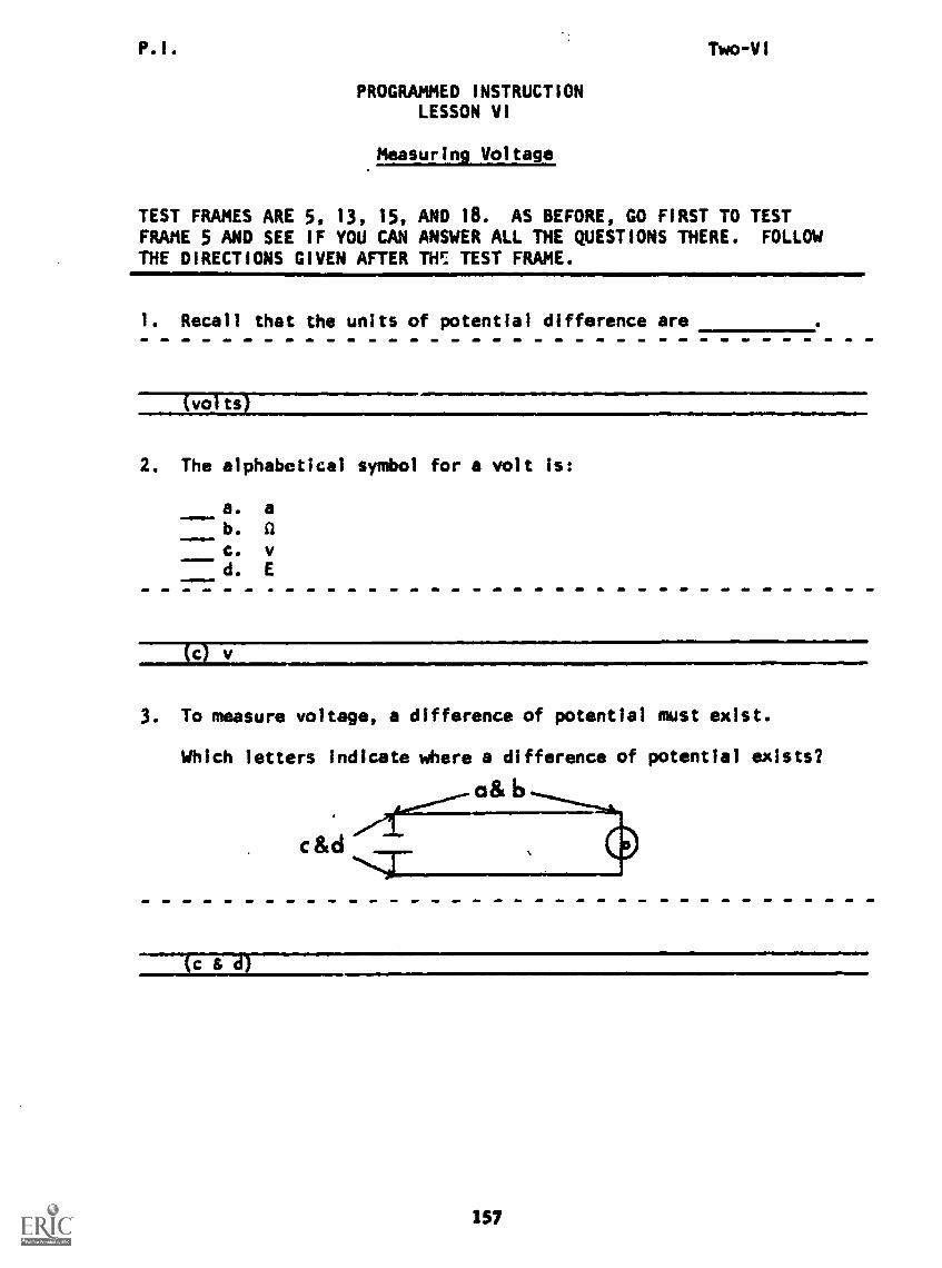
P.I.
PROGRAMMED INSTRUCTIONLESSON VI
Measuring Voltage
TEST FRAMES ARE 5, 13, 15,FRAME 5 AND SEE IF YOU CANTHE DIRECTIONS GIVEN AFTER
Two-VI
AND 18. AS BEFORE, GO FIRST TO TESTANSWER ALL THE QUESTIONS THERE. FOLLOWTill: TEST FRAME.
1. Recall that the units of potential difference are
(volts1
2. The alphabetical symbol for a volt is:
a. a
b. Qc. vd. E
3. To measure voltage, a difference of potential must exist.
Which letters Indicate where a difference of potential exists?
a& b
c&d
c&d)
157

BEST COPT AVAllialk. Two-VI
4. In a complete electrical circuit, a difference of potentialcan occur only:
1. at the terminals of a source.2. at the terminals of a load.
Circle the letters that indicate where a difference of potentialcan occur. Arl
a and
5. Indicate the point or points where a potential difference exists.
9
(THIS IS A TEST FRAME. COMPARE YOUR ANSWERS WITH THE CORRECT
ANSWERS GIVEN AT THE TOP OF THE NEXT PAGE.)
1S8
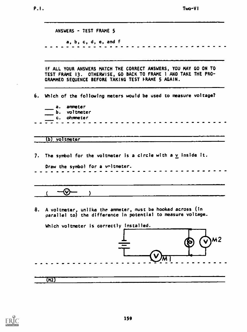
P.I. Two -VI
ANSWERS - TEST FRAME 5
a, b, c, d, e, and f
IF ALL YOUR ANSWERS MATCH THE CORRECT ANSWERS, YOU MAY GO ON TOTEST FRAME 13. OTHERWISE, GO BACK TO FRAME 1 AND TAKE THE PRO-GRAMMED SEQUENCE BEFORE TAKING TEST FRAME 5 AGAIN.
6. Which of the following meters would be used to measure voltage?
a. ammeterb. voltmeterc. ohmmeter
IMII11111
vo tmeter
7. The symbol for the voltmeter is a circle with a v Inside it.
Draw the symbol for a voltmeter.
8. A voltmeter, unlike the ammeter, must be hooked across (in
parallel to) the difference in potential to measure voltage.
Which voltmeter is correctly installed.
M2
(M2)
159
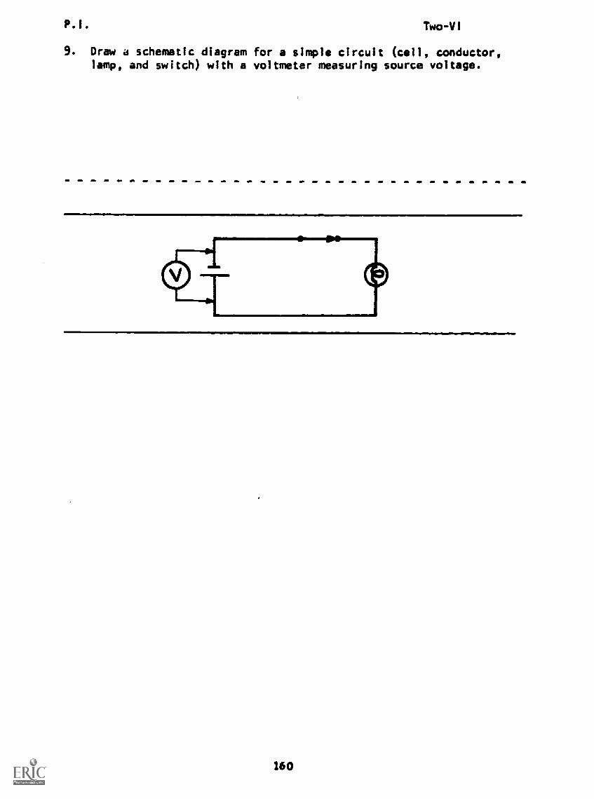
P.I. Two-VI
9. Draw a schematic diagram for a simple circuit (cell, conductor,lamp, and switch) with a voltmeter measuring source voltage.
160
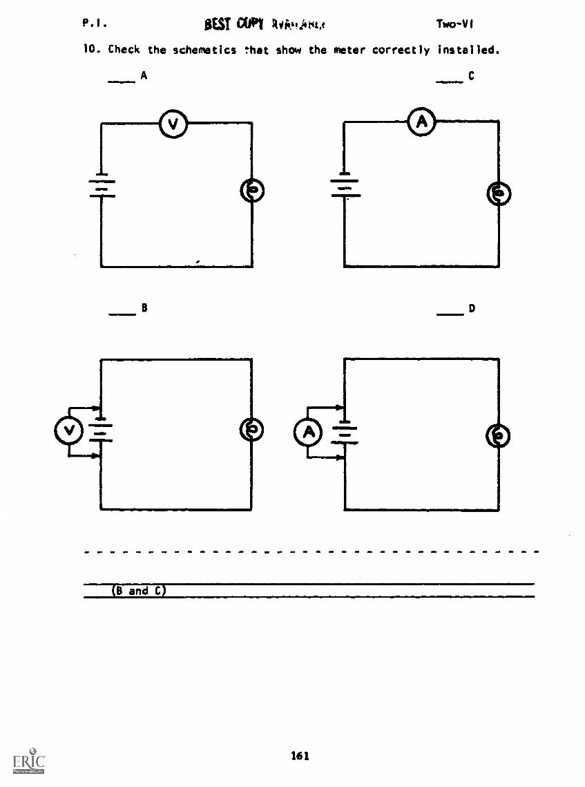
P.1. BEST CO P11 44ieptJerit.i TwoVI
10. Check the schematics 'hat show the meter correctly installed.
AMINMEI..111.
TB
C
(B and C)
161
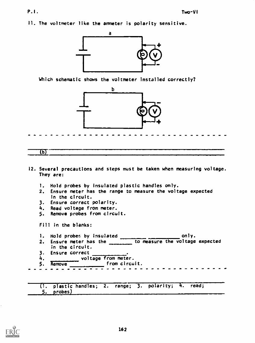
P.1. Two-V1
11. The voltmeter like the ammeter is polarity sensitive.
Which schematic shows the voltmeter installed correctly?
b
12. Several precautions and steps must be taken when measuring voltage.They are:
1. Hold probes by insulated plastic handles only.2. Ensure meter has the range to measure the voltage expected
in the circuit.3. Ensure correct polarity.4. Read voltage from meter.5. Remove probes from circuit.
Fill in the blanks:
1. Hold probes by insulated only.
2. Ensure meter has the to measure the voltage expectedin the circuit.
3. Ensure correct4. voltage from meter.5. Remove from circuit.
(1. plastic handles; 2. range; 3. polarity; 4, read;
5. _probes)
162
P.I.
13. Write the steps and precautions used to measure voltage.
1.
Two -V I
2.
3.
.4.
5.
(THIS IS A TEST FRAME. COMPARE YOUR ANSWERS WITH THE CORRECTANSWERS GIVEN AT THE TOP OF THE NEXT PAGE.)
163
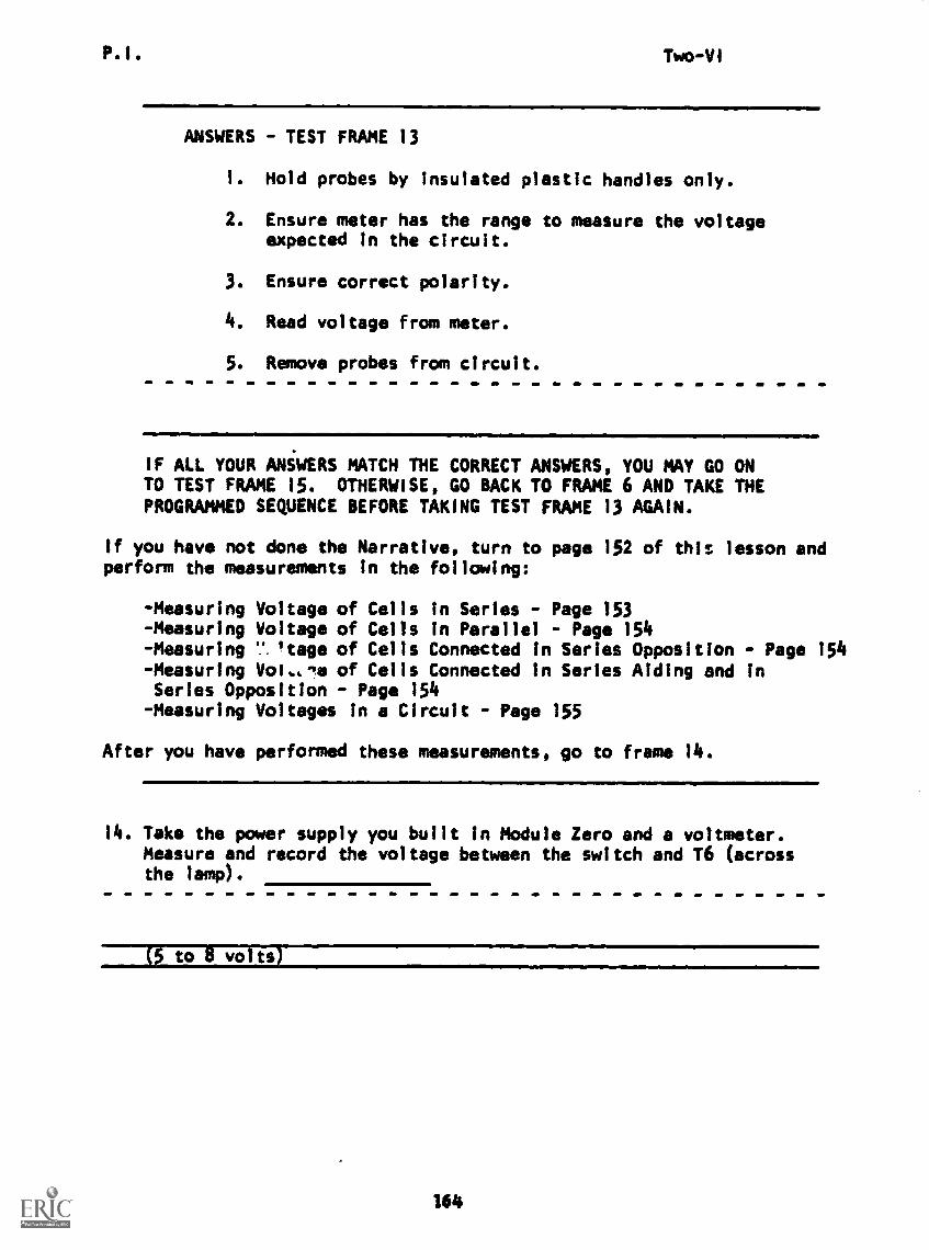
P.I. Two-VI
ANSWERS - TEST FRAME 13
I. Hold probes by insulated plastic handles only.
2. Ensure meter has the range to measure the voltageexpected in the circuit.
3. Ensure correct polarity.
4. Read voltage from meter.
5. Remove probes from circuit.
IF ALL YOUR ANSWERS MATCH THE CORRECT ANSWERS, YOU MAY GO ONTO TEST FRAME 15. OTHERWISE, GO BACK TO FRAME 6 AND TAKE THEPROGRAMMED SEQUENCE BEFORE TAKING TEST FRAME 13 AGAIN.
If you have not done the Narrative, turn to page 152 of this lesson andperform the measurements in the following:
-Measuring Voltage of Cells in Series - Page 153- Measuring Voltage of Cells in Parallel - Page 154- Measuring 'tage of Cells Connected in Series Opposition - Page 154- Measuring Voi,,le of Cells Connected in Series Aiding and inSeries Opposition - Page 154
- Measuring Voltages in a Circuit - Page 155
After you have performed these measurements, go to frame 14.
14. Take the power supply you built in Module Zero and a voltmeter.Measure and record the voltage between the switch and T6 (acrossthe lamp).
(5 to 8 volts)
164

P.I. Two-VI
15. Build the simple circuit according to the schematic below.
D
Measure and record the following voltages:
a. at the source.b. across the load.c. across open switch.d. across straight wire between points B and F
(THIS IS A TEST FRAME. COMPARE YOUR ANSWERS WITH THE CORRECTANSWERS GIVEN AT THE TOP OF THE NEXT PAGE.)
165
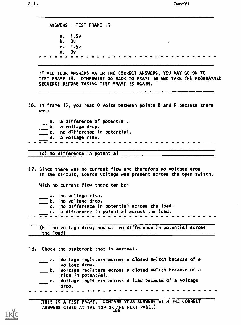
Two-VI
ANSWERS - TEST FRAME 15
a. 1.5vb. Ovc. 1.5v
d. Ov
IF ALL YOUR ANSWERS MATCH THE CORRECT ANSWERS, YOU MAY GO ON TOTEST FRAME 18. OTHERWISE GO BACK TO FRAME 14 AND TAKE THE PROGRAMMEDSEQUENCE BEFORE TAKING TEST FRAME 15 AGAIN.
16. In frame 15, you read 0 volts between points B and F because therewas
a. a difference of potential.b. a voltage drop.c. no difference in potential.d. a voltage rise.
(c) no difference in potential
17. Since there was no current flow and therefore no voltage dropin the circuit, source voltage was present across the open switch.
With no current flow there can be:
1110=0
a. no voltage rise.b. no voltage drop.c. no difference in potential across the !dad.d. a difference in potential across the load.
tb. no voltage drop; and c. no difference in potential acrossthe load)
18. Check the statement that is correct.
a. Voltage registers across a closed switch because of avoltage drop.
b. Voltage registers across a closed switch because of arise in potential.
c. Voltage registers across a load because of a voltagedrop.
(THIS IS A TEST FRAME. COMPARE YOUR ANSWERS WITH THE CORRECT
ANSWERS GIVEN AT THE TOP OF THE NEXT PAGE.)16e
P.I. Two-VI
ANSWER - TEST FRAME 18
c. Voltage registers across a load because of avoltage drop.
IF YOUR ANSWER IS INCORRECT, GO BACK TO FRAME 16 AND TAKE THEPROGRAMMED SEQUENCE.
IF YOUR ANSWER IS CORRECT, YOU MAY TAKE THE PROGRESS CHECK, ORYOU MAY STUDY ANY OF THE OTHER RESOURCES LISTED. IF YOU TAKETHE PROGRESS CHECK AND ANSWER ALL THE QUESTIONS CORRECTLY, YOUHAVE MASTERED THE MATERIAL AND ARE READY TO TAKE THE MODULETEST. SEE YOUR INSTRUCTOR.
IF YOU DECIDE NOT TO TAKE THE PROGRESS CHECK AT THIS TIME, ORIF YOU MISSED ONE OR MORE QUESTIONS, STUDY ANY METHOD OFINSTRUCTION YOU WISH UNTIL YOU HAVE ANSWERED ALL THE PROGRESSCHECK QUESTIONS CORRECTLY. THEN SEE YOUR INSTRUCTOR AND ASKTO TAKE THE MODULE TEST.
In this frame sequence you learned (1) the steps for voltagemeasurement and (2) how to use a simple voltmeter.
167
SUMMARYLESSON VI
Measuring Voltage
Voltage can be measured only across points between which thereis a difference of potential; the usual way for this to happenis for the two points to have different amounts of electricalcharge associated with them. This condition exists in parts ofa circuit where there is an EMF generated (voltage rise) or energyloss (voltage drop).
Energy is put into a circuit at its source and used by the load,for example, the light bulb, toaster, radio, etc. Voltage 17measured between the ends of a source or a load, but it usuallycannot be measured between the ends of a piece of wire connect-ing these parts because usually there is almost no voltage riseor drop through a conductor.
The device used to measure voltage is called a voltmeter. Its
schematic symbol 1 , and it is always connected
between two points when you want to know their potential differ-ence. Unlike current measurement, the circuit does not haveto be broken to measure voltage. The steps in using a voltmeterfor low (30v or less) voltages are:
1. Hold the probes by the insulated portions only.2. Be certain the voltage Is not higher than the meter can
measure.3. Observe polarity when measuring DC voltages.4. Read the voltage and remove the probes from the circuit.
If you feel you need more Information about measuring voltage,continue studying lesson VI; if not, perform the experimentMeasuring Voltages at the end of the Narrative for this lesson.
NOW YOU MAY TAKE THE PROGRESS CHECK OR STUDY ANY OTHER OF THERESOURCES LISTED. IF YOU TAKE THE PROGRESS CHECK AND ANSWER ALLTHE QUESTIONS CORRECTLY, YOU HAVE MASTERED THE MATERIAL AND ARE READY
TO TAKE THE MODULE TEST. SEE YOUR INSTRUCTOR.
IF YOU DECIDE NOT TO TAKE THE PROGRESS CHECK AT THIS TIME, OR IFYOU MISSED ONE OR MORE QUESTIONS, STUDY ANY METHOD OF INSTRUCTIONYOU WISH UNTIL YOU HAVE ANSWERED ALL THE PROGRESS CHECK QUESTIONS
CORRECTLY. THEN SEE YOUR INSTRUCTOR AND ASK TO TAKE THE MODULE
TEST.
168