Embed Size (px)
Citation preview
ED 094 147
TITLEINSTITUTION
SPONS AGENCY
PUB DATENOTEAVAILABLE FROM
DOCUMENT RESUME
88 CE 001 647
We Are Geared for Power Mechanics.Louisiana State Dept. of Education, Baton Rouge.;Natchitoches Parish School Board, La.Bureau of Elementary and Secon&r.ry Education(DHEW/OE), Washington, D.C.[72]169p.Mr. Trent Melder, Coordinator, Natchitoches CentralHigh School, Natchitoches, Louisiana 71457 ($2.50)
EDRS PRICE MF-$0.75 HC-$7.80 PLUS POSTAGEDESCRIPTORS Autoinstructional Aids; *Auto Mechanics; Curriculum
Guides; Individualized Instruction; Industrial Arts;*Instructional Materials; Job Skills; PerformanceBased Education; *Power Mechanics; Secondary Grades;Skill Development; Teacher Developed Materials;*Technical Education; Training Objectives; Units ofStudy (Subject Fields)
IDENTIFIERS Elementary Secondary Education Act Title III; ESEATitle III; Louisiana
ABSTRACTThe instructional materials developed on power
mechanics are based on the concept of performance objectives asorganized by EPIC Diversified Systems Corporation. Objectives withinthe document are divided into four categories; (1) programobjectives, (2) performance objectives, (3) process objectives, and(4) activities. These are categorized by a numbering system precedingeach objective or activity. This identification system allowsimmediate identification of the objectives covered and assists inestablishing a Project Monitoring System (PMS). The first 11 pages ofthe document give a brief description of the 15 program objectives; alist of the tools, materials, and equipment needed; and a shortorientation program. The remainder of the document is divided intopower mechanic units which are comprised of evaluation materials,worksheets, guides, tests, and a bibliography preceded by a list ofequipment, films, and other supplies to be used in each unit. Athree-page general bibliography is included. (BP)
NATCHITOCHE3 CENTRALU I DEPARTMENT OF HEALTH,
EDUCATION IIWELCARENATIONAL INSTITUTE OF
EDUCATIONTHIS DOCUMENT HAS BEEN REPROOuCED EXACTLY AS RECEIVED FROMTHE PERSON OR ORGANIZATION ORIGINATING IT POINTS OF VIEW OR OPINIONSSTATED DO NOT NECESSARILY REPRESENT OFF IC1AL NATIONAL INSTITUTE OFEDUCATION POSITION OR POLICY
HIGH_ SCHOOL
1'1E%. AluiCiNATCH 1TOCHE4 LOUISIANA

TABLE OF CONTENTS
i
ii-
1
Genor...! rials, and Equipment 4
Or e:11 i.
9
11
Sher S 7.c-e t
ice : s 21
24
Tools a-d t r Functions
50Ictivitics 55
Prevertive Xaintenancef.'bjects 65ictivides 74
89
94
FuelObjc.c05-7 103
ties 105
Exhaut Svs'timOhjecvs 110Activi.cie 112
Tune-Up Procc:duresOh jc ti 117ActivicLes 120
General EnieUbjectivs 126Activitic 131
Braking SystemObjectives 141Activitie 145
Front End S?,,;nension SystemObjective5-: 151Activities 154
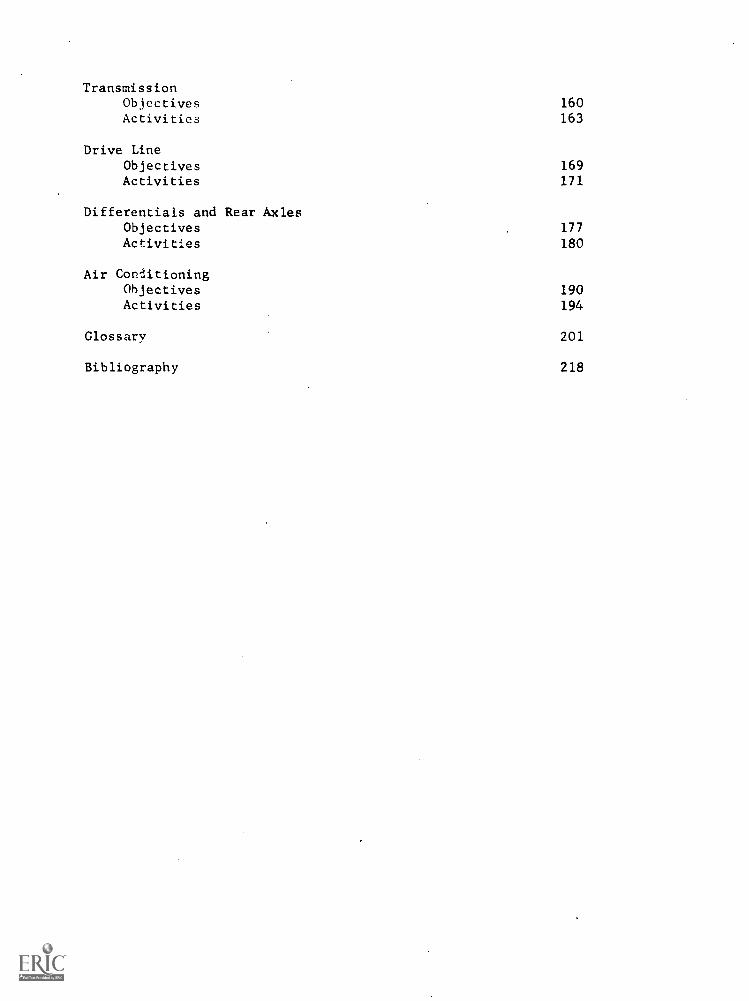
TransmissionObjectives 160Activities 163
Drive LineObjectives 169Activities 171
Differentials and Rear AxlesObjectives 177
Activities 180
Air ConditioningObjectives 190Activities 194
Glossary 201
Bibliography 218
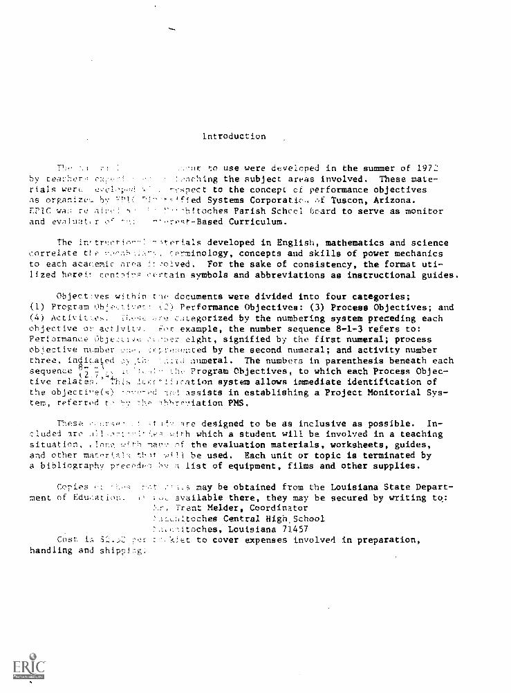
Introduction
to use were developed in the summer of 1972by teacher ::nching the subject areas involved. These mate-rials wen, ecelcp, r:'spect to the concept ci performance objectivesas organize by '7'!' ''? ^,fied Systems Corporatic.i Tuscon, Arizona.EPIC wa; `:!7-'nitoches Parish School hoard to serve as monitorand evaluatr rest-Based Curriculum.
The in'triwrin: 73!.prfals developed in English, mathematics and sciencecorrelate tto terminology, concepts and skills of power mechanicsto each acacemic rlrea For the sake of consistency, the format uti-lized hereiT confr= certain symbols and abbreviations as instructional guides.
Object:ves within tie documents were divided into four categories;(1) Program (2) Performance Objectives: (3) Process Objectives; and(4) Activites. c:Itegorized by the numbering system preceding eachobjective o; activitv. example, the number sequence 8-1-3 refers to:Performance Aje:.1,'e eight, signified by the first numeral; processobjective nnmber ::::-e::ented by the second numeral; and activity numberthree, indicated ..td numeral. The numbers in parenthesis beneath eachsequence i2.7 Program Objectives, to which each Process Objec-tive relat'e.' 4:his r:::'LfIcation system allows immediate identification ofthe objectie(s) assists in establishing a Project Monitorial Sys-tem, referred t 1t-Pyiation PNIS.
ire designed to be as inclusive as possible. In-cluded ire :!th which a student will be involved in a teachingsituation, .71ry r,f the evaluation materials, worksheets, guides,and other materi w111 be used. Each unit or topic is terminated bya bibliography precede-; :Iv 1 list of equipment, films and other supplies.
CcTies il..; may be obtained from the Louisiana State Depart-ment of Education. available there, they may be secured by writing to:
Trent Helder, Coordinator:_,_.4oches Central High, School,,=::itoches, Louisiana 71457
Cost is S2. :Y1, .1.ejet to cover expenses involved in preparation,handling and shippL-1g:
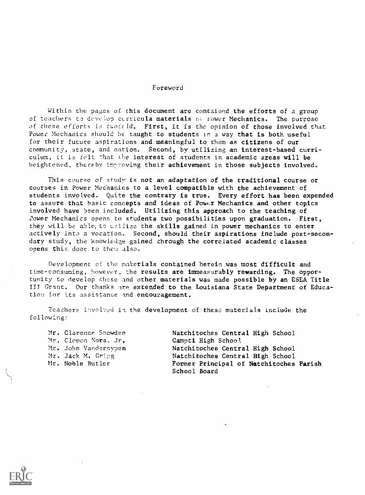
Foreword
Within the pages of this document are contained the efforts of a groupof teachers to develop cLrricula materials o; fower Mechanics. The purposeof these efforts twoCcld. First, it is the opinion of those involved thatPower Mechanics should be taught to students in a way that is both usefulfor their future aspirations and meaningful to them as citizens of ourcommunity, state, and nation. Second, by utilizing an interest-based curri-culum, it is felt that the interest of students in academic areas will beheightened, thereby irnl,oving their achievement in those subjects involved.
This course of study is not an adaptation of the traditional course orcourses in Power Mechanics to a level compatible with the achievement ofstudents involved. Quite the contrary is true. Every effort has been expendedto assure that basic concepts and ideas of PowLr Mechanics and other topicsinvolved have been included. Utilizing this approach to the teaching ofdower Mechanics opens to students two possibilities upon graduation. First,they will be able, to uilize the skills gained in power mechanics to enteractively into a vocation. Second, should their aspirations include post-secon-dary study, the knowledge gained through the correlated academic classesopens this door to them also.
Development of the materials contained herein was most difficult andtime-consuming, however, the results are immeasurably rewarding. The oppor-tunity to develop these and other materials was made possible by an ESEA TitleIII Grant. Our thanks or extended to the Louisiana State Department of Educa-tion for its assistance and encouzagement.
Teachers invol'.-ed 1_1 the development of thes:: materials include thefollowing:
Mr. Clarence Snowden.Mr. Clemon Nora, Jr.Mr. John VandersypenMr. Jack M. GrigMr. Noble Butler
Natchitoches Central High SchoolCampti High School.Natchitoches Central High SchoolNatchitoches Central High SchoolFormer Principal of Natchitoches ParishSchool Board
POWER MECHANICS (P.M.)
Program Objectives
1. Upon the completion of the year 1972-73, the Power Mechanicsstudents will demonstrate a 707. increase in knowledge of Orientationas measured by a teacher-made test.
2. Upon the completion of the year 1972-73, thewill demonstrate a 707. increase in knowledgemeasured by a teacher-made test.
3. Upon the completion of the year 1972-73, thewill demonstrate a 70% increase in knowledgeFunction as measured by a teacher-made test.
Power Mechanics studentsof Shop Safety as
Power Mechanics studentsof Tools and their
4. Upon completion of the year 1972-73, the Power Mechanics studentswill demonstrate a 707. increase in knowledge of PreventiveMaintenance as measured by a teacher-made test.
5. Upon the completion of the year 1972-73, thewill demonstrate a 70% increase in knowledgeSystem as measured by a teacher-made test.
6. Upon the completion of the year 1972-73, thewill demonstrate a 70% increase in knowledgemeasured by a teacher-made test.
7. Upon the completion of the year 1972-73, thewill demonstrate a 70% increase in knowledgeas measured by a teacher-made test.
Power Mechanics studentsof the Electrical
Power Mechanics studentsof the /ma-System as
Power Mechanics studentsof the Exhaust System
8. Upon the completion of the year 1972-73, the Power Mechanicsstudents will demonstrate a 70% increase in knowledge of Tune-UpProcedures as measured by a teacher-made test.
9. Upon the completion of the year 1972-73, the Power Mechanics studentswill demonstrate a 707. increase in knowledge of General Enginesas measured by a teacher-made test.
10. Upon the completion of the year 1972,73, thewill demonstrate a 707, increase in knowledgeas measured by a teacher-made test.
11. Upon the completion of the year 1972,73, thewill demonstrate a 707. increase in knowledgeSystem as measured by a teacher-made test.
Power Mechanics studentsof the Braking Systems
Power Mechanics studentsof the Front Suspension
12. Upon the completion of the year 1972-73, the Power Mechanicsstudents will demonstrate a 707. increase in knowledge of Trans-missions as measured by a teacher-made test.
13. Upon the completion of the year 1972-73, the Power Mechanicsstudents will demonstrate a 70% increase in knowledge of the DriveLine as measured by a teacher-made test.
14. Upon the completion of the year 1972-73, the Power Mechanicsstudents will demonstrate a 70% increase in knowledge of Differentialsand Rear Axles as measured by a teacher-made test.
15. Upon the completion of the year 1972-73, the Power Mechanics studentswill demonstrate a 70% increase in knowledge of Air-Conditioningas measured by a teacher-made test.
M,I.TERIALS
AND EQUIPMENT FOR
UNITS I.XV
ALr Condition To.)1 Kit.
Air Condition Unit (Co7plete) Auto
Alternator.
Ammeter
Automobile (Complete)
Automobile Repair Manuel
Balancers
Battery-b volt.
Battery-12 volt
Bearing Drive on Punch'
Bearing Puller
Booster Cylinder
Brake 71v.id
Brake Shoes
Brakinz SvstP,:n
Car Stands
Chalk Board
Charts
Cleaning Solvent
Compression Gauge
Compression Tester
Concentric Valve-Seat Grinder
Creeper
Cylinder 11,2ad
Cylinder Leakage Testet
Dial Indicator
Disc Brake
Distributor/ConLacr Point
Distributor/Magnetic Pickup
Distributor/Transistorized System
Drain Pan
Engine Block (Assembly)
Engine Stands
Exhaust Gas Analyzer
Exhaust System (CDmplee)
Filmstrips
Finder Cover
Flask
Floor Jack
Freon
Fuel System (Com,plet':2)
Gas Engine (small)
Gasoline
Generator
Grease Seal
Hand Tool Kit
Headlight Tester
Hex-Head Bolt
Horn Relay
Hunter's Tune-in Wheei Balance
5
Hydometer
Hydraulic Jack
IgLition Analyz,r #51 (King Tester)
Jack
Leak Detector
Lift (Hydraulic)
Lock Washer (plain, external, internal, external-internal)
Manufacturer's Manuals
Master Cylinder Cap/Special Tool
Master Cylinder (dual Si single)
Mechanic Towels
Mechanic's Tool Kit
Micometer
Muffler
Multiple Cylinder Engine
Oil Can Opener
Oil Pan Wrench
Phillip Head Screwdriver
Projector
Rear Axle Assembly
Rear Axle (Special Tool Kit)
Run-out Gauge
Safety Stands
Seal Beam Headlight (#560 & 561)
Self-Adjusting Brakes
Shock Absorbers
Slides
Solenoid
6
CRIENTATION
1-0-0 Upon completion of the job the students will apply their knowledgeof the power mechanics orientation by scoring 70% or above on ateacher-made test.
1-1-0 The project teacher during one will define power mechanicsas monitored by the project monito_L ,; system.
1-1-1 Discuss the definition of Power Mechanics. (Handout 1-1-1)1-1-2 Describe a mechanic by using the technical definition of a
mechanic. (Bottom of handout 1-1-1)
2-0-0 At the end of the job the students will apply their knowledge ofthe location of plant facilities atd course requirements byscoring 707, or above on a teacher-made test.
2-1-0 During one class the project teacher will test course requirementsand position of facilities as monitored by the project monitoringsystem.
2-1-1 Students will tour the facility' with the instructors pointingout 1-:e areas of the shop.
2-1-2 Students will be shown location of washroom, dressing area,tool area, and the fire extinguishers.
2-1-3 Describe she time table requirements for their particular class.2-1-4 Discuss the grading scale and answer any questions.2-1-5 Allow students to orient themselves to the shop.2-1-6 Answer an' question from the students.
3-0-0 At the end of the job the students will apply their knowledge ofautomobile accessories by scoring 70% or above on a teacher-made test.
3-1-0 The proiect teacher during one class period will discuss infor-mation sheet containing many different types of automobileaccessories as monitored by the project monitoring system.
3-1-1 Discuss the use of a typical automobile owners guide.3-1-2 Ask students to list different accessories available on modern
automobiles.3-1-3 Allow the students to describe any accessories which could make
driving safer. (Handout 3-1-3)3-1-4 List some steps in the care and maintenance of these accessories.
4-0-0 Administer test over 1-1-0 through 3-0-0 Orientation.
71 -6/9
1-1-1 Handout - Definition of Power Mechanics
Power mechanics is the study of the rate of expanding, transmitting,and developing energy in the forms of natural, mechanical, steam, pneumatic,hydraulic, electrical and thermal power to control its potential toproduce work.
natural - produced by nature such as coal, oil wind
mechanical - having to do with machinery
steam - water in the form of vapor or gas
pneumatic - having to do with air and other gases
hydraulic - science dealing with water and other liquids in motion
electrical - having to do with electricity
thermal - having to do with heat
Definition of a mechanic - A skilled workman who makes, repairs, andassembles machinery or mechanical parts.
3-1-3
AUTOMOBILE ACCESSORIES
1. Air conditioner
2. A M Radio - Solid State
3. F M Radio
4. Bumper guards
5. Carpeting
6. Console
7. Deluxe wheel covers
8. Electric Clock
9. 4 Speed manual transmission
10. Heavy duty suspension
11. Inside hood release
12. 3 Speed manual floor shift
13. Automobile transmission
14. Variable speed windshield wipers
15. Vinyl room
16. Tinted glass
17. Power steering
18. Positive traction
19. Power disc brakes
20. Racing mirrors
21. Rear window defogger
22. Luggage rack
23. Sun roof
24. Power windows
12
25. Stereo and Cassette tape
26. Automatic headlight dimmer
27. Power seats
28. Tilt and telescope rim blow steering wheel
29. Wheel opening skirts
30. Auto speed control
31. Power door locks
32. Fender mounted turn signals
33. Electronic ignition system
34. Door edge protectors
35. Engine block heater
36. Mirrow manual & remote control
37. Power bucket seats
38. Rear seat speaker
39. Trailer hitch
40. Undercoating
41. Oil gauges, amp, water temp, cigarette lighter
13
4-0-0
STUDY QUESTIONS
1. Define:
Power Mechanics
Automobile Accessories
2. Discuss some reasons for studying power mechanics.
3. List 15 accessories which can be bought with a new automobile.
4. List 5 accessories which could help in a safer automobile.
r
14
4-0-0
TEST
POWER MECHANICS
1. What is a good specific gravity of battery electrolyte?
2. Define A.C. current.
3. Define D.C. current.
4. What regulates the voltage produced by an alternator?
5. What does an automobile ammater measure?
6. Name three parts of a spark plug.
7. Explain the purpose of a relay.
8. List three parts of the cranking motor.
9. What happens to the drive pinion of the starter after the engine starts?
10. Define: Hydraulics
Power Mechanics
11. Name four parts of the braking system.
12. List materials used in brake linings.
13. Name ten automobile accessories.
14. List five accessories which could help in having a safer automobile.
15. Why should old oil be allowed to drain?
16. What methods are used to keep the oil in the crankcase free from dirtand grit?
17. List what precautions should be taken when lubricating an automobile.
18. How would you clean an oil crankcase ventilator?
19. What type of oil is used in standard transmissions?
20. Why should all parts be washed and dried?
21. Why is the wheel rotated while adjusting the bearings?
22. What is a frozen bearing?
15
23. Does the axle sh IL bearing need packing before installing?
24. What should be done to leather seals before they are installed?
25. Explain the effects a broken ground wire has on a sealed beam light.
26. What takes up the slack when the adjustment is loosened?
27. Define a light filament.
28. How can you identify the front from tt< rear of a muffler?
29. How can a tail pipe being burned out in front of the gas tank causepoor gas mileage?
30. What is the advantage of the independent suspension system?
31. How does the stabilizer bar work?
32. Why is wheel alignment important?
33. What measuring instrument can be used in measuring the diameter ofa shaft?
34. Describe the procedure of taking a measurement with a micrometer.
35. Why is it necessary to time the valves?
36. Explain the purpose of a cam lobe.
37. List two types of vale. lifters.
38. What is the purpose of an air filter or air cleaner for a carburetor?
39. What is meant by idle speed?
40. How often should air filters be serviced?
41. How is fuel level controlled in the carburetor?
42. What purpose does the muffler serve?
43. What is a torque multiplier? Where is one used in the automobile?
44. List the four stages or strokes of engine operation.
47. What are the two commonly used oil pumps?
46. What purpose does the gasket serve?
47. Name two types of oil filters.
48. You should never over-lubricate a generator. Why?
16

49. What advantage is there in making the propeller shaft in two pieces?
50. Why must the line he cirefullv balanced?
51. Why is the tune-up procedure more important for modern engines?
52. Name four meters found on the king ignition analyzer.
53. What does T.D.C. stand for in power mechanics?
54. What are the two basic types of axles:
55. is the central unit in whichhydraulic pressure is developed in the braking system.
56. When using a dual master cylinder and the front system failed theportion of the system will stop the vehicle.
57. In a two piece drive line, a bearing must be used.
58. Most propeller shafts are solid. True or False?
59. The differential pinion gear will mesh with thegear in the differential.
17
SAFETY
1-0-0 At t; sluje,::s will apply their knowledgeol 'rry suorin, .0% ol; a teacher-made test.
1-1-0 Tb, instrur during oneclass .;bo-;, safety as mot,Uo:ed ny the project
1-1-1 Dis,'.uss sdfcty Clianiout-C,.:tal Safety Habits).1-1-2 Dis.ss
a,nse i9 b,st safety practice(J) before you act
1-1-3 and don'ts of shop safety1-1-4 Demc.ust.: sa:-, use of hc emery grinder.1-1-5 Deoustrue way of jacktuc an auLomobile.1-1-6 Discuss different flammable mixtures and their combustion
temnerutur,.s.
: --
1-1-7 stunts rcAsons studying shop safet'..
2-0-0 S7'11;,;1;', :I apply their knowledgef.... ; s teacher-made test.
2-1-0 Th.,.! Pc,w,r .:nani;:s instructor will discuss during one classperio,! saI:t whi:'h will Se monitored by the
2-1-1 She s inc-lustiles use to promote safe practices.2-1-2 Ds e ruerannL'a in some industries to induce
fe
2-1-3 Di. . ()!, of Saf,.tv Em.;Lneer in Industry.2-1-4 A tomf: to lecture on how he main-
a-2-1-5 -nts ths1 most often in an industrial
atrosber. List any industrial accidents that have happenedIa
2-1-6 Discuss a newspaper clipping which describes an industrial
2-1-7 hav (ioue to prevent such an industrialaccith,y
1,61 0/0/2.1
3-0-0 Upon completiledge of rul.?s
made test.
. the ;tudents will demonstrate their know-: st aid fundamentals by scoring 70% on a teacher-
3-1-0 Project teacher will instruct each student in the correct method offilling out Data Sheets and Accident Forms as monitored by the ir-structor.
3-1-1 List the reasons for coming strai , the instructor if any injuryoccurs, no matter how many.
3-1-2 Handout Accident Forms and require al] students to complete them.3-1-3 Handout Information forms and require each student to fill in
appropriate blanks.3-1-4 Administer ,i.v:ety test to all students required before working.3-1-5 Write a pledge to be safe while working in the shop.
4-0-0 Upon completion o the job, the students will demonstrate their abilityto apply his knowledge of personal group safety by scoring 70% on ateacher-made test.
4-1-0 The project tea,:her during one class will discuss the Group SafetyAdministrators as monitored by the project teacher observation.(See Handout it !:-1-3)
4-1-1 Demonstrate the need of a safety foreman in a shop.4-1-2 Discuss with students some safety hints th..y may have.
(Handout: Practical Safety Hints.)4-1-3 Handout: Detail Duties of Student Personnel Officers.4-1-4 Discuss the duties of a general superintendent.4-1-5 Discuss the duties of a recording clerk.4-1-6 Discuss the duties of a tool checker.4-1-7 Discuss the duties of a safety foreman.4-1-8 Administer verbal quiz on personal group safety.
5-0-0 At the end of the job, the students will apply their knowledge of re-porting an accident by scoring 70% on a teacher-made test.
5-1-0 The project teacher during one class will list the order of procedureto follow after an accident as monitored by teacher observation.
5-1-1 Discuss the importance of reporting to the teacher.5-1-2 Use an overhead projector to show an accident report form.5-1-3 Write short essay on how accidents occur.5-1-4 Discuss the reasons for calling the accident to the attention of
the principal.
Administer teacher-made test covering Interims
22
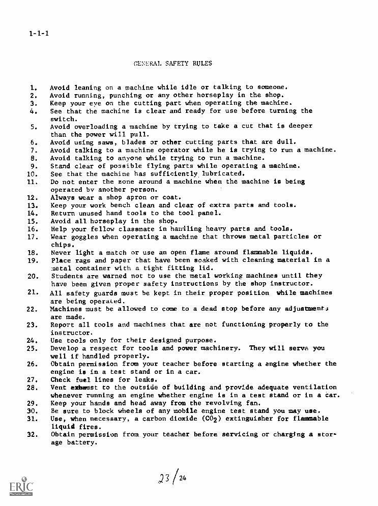
GENERAL SAFETY RULES
1. Avoid leaning on a machine while idle or talking to someone.2. Avoid running, punching or any other horseplay in the shop.3. Keep your eye on the cutting part when operating the machine.4. See that the machine is clear and ready for use before turning the
switch.5. Avoid overloading a machine by trying to take a cut that is deeper
than the power will pull.6. Avoid using saws, blades or other cutting parts that are dull.7. Avoid talking to a machine operator while he is trying to run a machine.8. Avoid talking to anyone while trying to run a machine.9. Stand clear of possible flying parts while operating a machine.
10. See that the machine has sufficiently, lubricated.11. Do not enter the zone around a machine when the machine is being
operated by another person.12. Always wear a shop apron or coat.13. Keep your work bench clean and clear of extra parts and tools.14. Return unused hand tools to the tool panel.15. Avoid all horseplay in the shop.16. Help your fellow classmate in handling heavy parts and tools.17. Wear goggles when operating a machine that throws metal particles or
chips.18. Never light a match or use an open flame around flammable liquids.19. Place rags and paper that have been soaked with cleaning material in a
metal container with a tight fitting lid.20. Students are warned not to use the metal working machines until they
have been given proper safety instructions by the shop instructor.21. All safety guards must be kept in their proper position while machines
are being operated.22. Machines must be allowed to come to a dead stop before any adjustment4
are made.23. Report all tools and machines that are not functioning properly to the
instructor.24. Use tools only for their designed purpose.25. Develop a respect for tools and power machinery. They will serve you
well if handled properly.26. Obtain permission from your teacher before starting a engine whether the
engine is in a test stand or in a car.27. Check fuel lines for leaks.28. Vent exhaust to the outside of building and provide adequate ventilation
whenever running an engine whether engine is in a test stand or in a Car.29. Keep your hands and head away from the revolving fan.30. Be sure to block wheels of any mobile engine test stand you may use.31. Use, when necessary, a carbon dioxide (CO2) extinguisher for flammable
liquid fires.32. Obtain permission from your teacher before servicing or charging a stor-
age battery.
) 3 /24
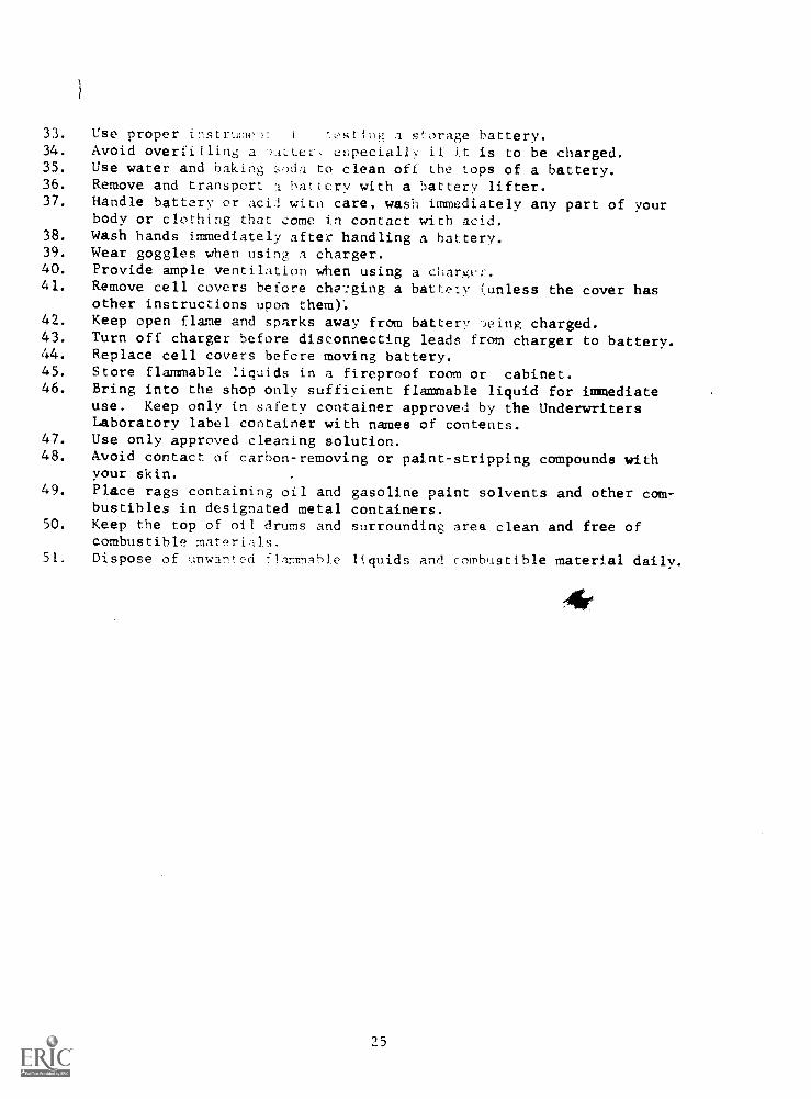
33. Use proper instrume: I c,stivis; a storage battery.34. Avoid overfilling a ')ALLec L!specially if &t is to be charged.35. Use water and baking :;oda to clean off the tops of a battery.36. Remove and transport a battery with a battery lifter.37. Handle battery or aci/ with care, wash immediately any part of your
body or clothing that come in contact with acid.38. Wash hands immediately after handling a battery.39. Wear goggles when using a charger.40. Provide ample ventilation when using a charger.41. Remove cell covers before charging a battely (unless the cover has
other instructions upon them)'.42. Keep open flame and sparks away from battery .3eing charged.43. Turn off charger before disconnecting leads from charger to battery.44. Replace cell covers before moving battery.45. Store flammable liquids in a fireproof room or cabinet.46. Bring into the shop only sufficient flammable liquid for immediate
use. Keep only in safety container approved by the UnderwritersLaboratory label container with names of contents.
47. Use only approved cleaning solution.48. Avoid contact of carbon-removing or paint-stripping compounds with
your skin.49. Place rags containing oil and gasoline paint solvents and other com-
bustibles in designated metal containers.50. Keep the top of oil drums and surrounding area clean and free of
combustible materials.51. Dispose of unwaned .1.1mmnhie liquids and combustible material daily.
25
H c0RDSAND ALL PORTABLE ToOES
1-1-6
1. See that extensioe cerL: of sufficient length.2. Check cord to set. that he is not frayed, nicked, or any insulation
broken.3. Check to see that ;Tale and female in good condition.4. Use only cords that `.hive provision for being :;rounded.5. Attach ground wire.6. Check all portable tools carefully, trigger cords, etc.7. Be sure your portable tools are grounded.8. Do not handleportable tools with wet hands.9. Do not stand on damp 4round or concrete when using portable tools.
WRENCHES
1. Always use the proper wrench when making adjustments on machines.
AMEF1CAN STANDARDS ASSOCIATIONSafety color code
RED-- THE FIRE PROTECTION COLORGeneral use: To point cut the location of fire protective equipment
such :r.s extinguishers, alarms, firedoors, fire blankets,.
Pipes: Sprinkler or other fire extinguishing system pipes.
ORANGE--THE ON-GUARD CflEORGeneral Use: To imAcate dangerous parts of machinery which could in-
jure personnel by cutting, crushing,For eLectrical hazzards such as interior of fuse andswitch box doors. Interior side of gear guards.
Pipes: Pipes containing materials which are poisonous, hot, easilyignited, explosive, or otherwise dangerous.
YELLOW- -THE WARNING COLORGeneral Use To point out conditions or installations which are likely
to cause bumping, stumbling, tripping, or falling. Usedas a band when making busy aisles, moving objects over-head, etc.
Pipes: Same as for orange.
GREEN--THE FIRST AID COLORGeneral Use: To mark location of first aid and safety equipment such as
medical kits, stretchers, respiratory and eye equipment,safety showers, etc.
Pipes: For pipes handling safe and non-valuable products such as water,air (under 300 lbs.), sugar solutions, etc.
26
BLUE,THE CAUTION COLORGeneral Use: precJuti-io ary warning to indicate that materials should
not be in use, moved or started except by qualified personnel,such as for temporary repairs. Sometimes used electricalcontrol boxes.
Pipes: For protective materials other than fire protection, such as gasesto counteract poisonous fumes, antidoted to dangerous Mats.
WHITEZONE MARKING COLORGeneral Use: To direct the flow of traffic and to accentuate sanitation
equipment, such as traffic lanes, non-hazardous aisle markings, waste receptacles, storage areas, corners.
Pipes: Safe materials. Same as green
PURPLE -- NUCLEAR RADIATION HAZARD COLORGeneral Use: To indicate nuclear radiation hazards. In common use is a
three spot triangular magenta against a yellow background.
Pipes: To indicate that the contents is of extra value and udually isnon dangerous.
Benefits of using color in industry
1. Less absenteeism from the job.
2. Increased morale and the worker's attitude.
3. Fewer accidents, hazards identified with color
4. Improved quantity and quality of production.
5. Better employee relations.
27
1-1-6a
::I.A.MNABLE LIQUIDS
Definition of terms:
Flammable liquids--or inflammable liquids (used synonymous) refer tomaterials that are susceptable to ignition.
Flash point--"The temperature at which the vapor given off from an oil orhydrocarbon will ignite momentarily in the air, in the presenceof a small flame."
The following information has been taken from the National Fire Pro-tection Association International Fire Prevention Handbook. Where directquotes have been made of pertinent information included in the handbook onthis topic.
Unsafe Storage Evaluation
In evaluating storage facilities for safety measures, check the following:
1. Leaky valves--each drop that goes unattended is a fire hazard.2. Be sure all vents are operating properly.3. If gauging devices are used, be sure no leaks are present around or with-
in the gauge.4. All filling lines and holes should be properly capped.S. Be sure that plenty of fresh air circulation is available around storage
area. (If stored in a building, vents to the outside of he storage roomshould be plentiful.)
6. Storage should a minimum of 20 feet from any type of flame, or heat(preferrably farther, depending upon type of liquids being stored andfacilities housing the liquids.)
7. All liquids shoulf: be stored in a fire proof cabinet or container designedfor that purpose.
Storage of Flammable Liquids
1. Never store more than necessary for :.mediate use.2. Allow plenty of room around stored containers for air to circulate freely.3. Always leave peaty of room for expansion in stored cans.4. If temperature y..ses any appriciable amount, it is advisable to check cans
to see that they do not have too much pressure creating a hazard. (If cansare puffed up, loosen lid carefully, releasing pressure.)
5. Store only the amount to be used immediately in roam where liquids are tobe used. This small amount should be stored in a steel cabinet or chesstype of storage for maximum safety.
28
Outside Storage (2,7-30)
1. If any great amount of flammable liquids are to be stored, store themaway from the building. The closeness of the building to ocher buildingswould depend upon the type of construction of the buildings and the flam-mability of the liquids to be stored.
2. In storing drums, store vertically if liquids are to be used and dispensethem with a pump.
3. If liquids are not to be used, store drums in a horizontal position on4" x 4" runners to allow maximum air circulation.
4. Building should be equipped with a fire resistant wall and door, and withsafety lights and switches.
5. If blower or suction fans are used, motors should be outside of the passageof vapors given off from the liquids. Fans should be driven by belts orshafts and not directly.
6. Paint building a light color if all possible. This reflects the heat fromthe sun more readily.
7. If drums are stored outside (or large tanks are used), paint then silver toreflect the greatest amount of heat possible.
8. Post signs around storage area designating danger involved in and aroundstorage area.
Dispensing and Handling Method (2, 7-32)
The hazard is not in storing flammable liquids so much as it is in theinterval between the storage and the actual use of the liquids. In otherwords, the transferring of the liquids from the storage facility to the areain which the liquids are to be used.
1. In dispensing liquids, a positive displacement pump should be used if thecontainer is too large to safety tilt and pour liquids.
2. If electric pumps are used, they should meet the standards set up by theNational Safety Council or the NFPA.
3. Liquids should be transferred in approved containers, and under no circum-stances should glass containers be used.
4. After liquids have been used, they should be capped and safely stored.
Cleaning Containers for Repairs (2, 7-85)
If containers are to be repaired by heating. they can be Prepared for saferepairs by:
1. Filling with water, leaving vent open for air.2. Steam cleaning, or3. Filling with an inert gas such as CO2 leaving an opening for fumes to be
carried out by the CO2.
29
Brush Painting and Spraying (2,7-36)
11. are are mAjor .:,.thods of painting. They are brush paintingand spray painting.
1. Brush painting in itself is virtually free frim accidents, but thecombustion deposits of flammable liquids on wiping rags is themain danger involved here. All rags should be placed in a safecontainer and disposed of daily.
2. Spray Painting. One of the major factors in safe spray room paint-ing is ventilation. This is necessary to the health of the personusing the room as well as to reducing the hazard of fire.
a. Select a finish or solvent which a flash point above 100°F ifat all possible.
b. Spray booths, if used, should be constructed out of metal andshould have an exhaust fam for removing spray fumes and harm-ful gases.
c. Exhaust fan motors should never be located in the spray boothorduct work. They should be located outside and either drivenby belt or shaft.
d. Only approved lighting and switches should be used in the sprayroom.
e. When cleaning the spray booth or room, wet entire area withwater. The residue collected in the booth is highly combustibleand could very easily be ignited by a spark from a paint scraper.
30
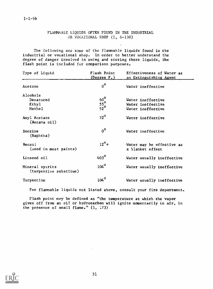
1-1-6b
FLAMMABLE LIQUIDS OFTEN FOUND IN THE INDUSTRIALOR VOCATIONAL SHOP (2, 6-130)
The following are some of the flammable liquids found in theindustrial or vocational shop. In order to better understand thedegree of danger involved in suing and storing these liquids, theflash point is included fur comparison purposes.
Type of Liquid Flash Point(Degree F.)
Effectiveness of Water asan Extinguishing Agent
Acetone 0° Water ineffective
AlcoholsDenatured 60
o
Ethyl 55°Methel 52
o
Water ineffectiveWater ineffectiveWater ineffective
Amyl Acetate 72° Water ineffective(Banana oil)
Benzine 0° Water ineffective(Naphtha)
Benzoi(used in most paints)
Linseed oil
Mineral spirits(turpentive substitue)
Turpentine
12o+Water may be effective asa blanket effect
403° Water usually ineffective
104° Water usually ineffective
104oWater usually ineffective
For flammable liquids not listed above, consult your fire department.
Flash point may be defined as "the temperature at which the vaporgiven off from an oil or hydrocarbon will ignite momentarily in air, inthe presence of small flame." (1, 173)
31
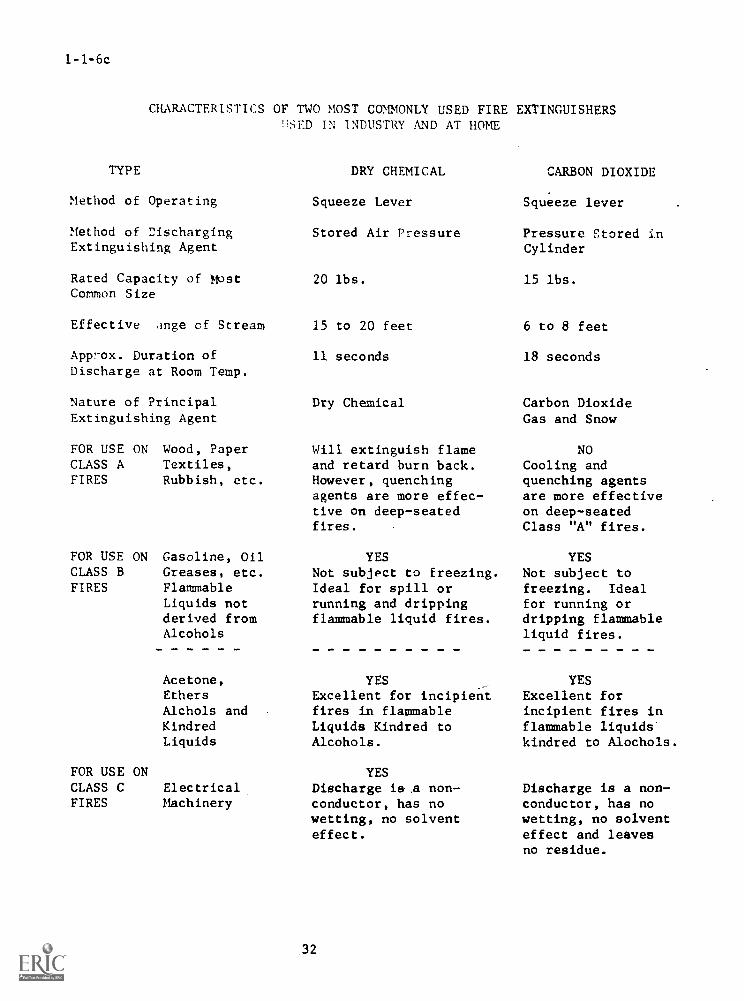
1-1-6c
CHARACTERISTICS OF TWO MOST COMMONLY USED FIRE EXTINGUISHERSUSED IN INDUSTRY AND AT HOME
TYPE
Method of Operating
Method of DischargingExtinguishing Agent
Rated Capacity of MostCommon Size
Effective tinge of Stream
App7-ox. Duration of
Discharge at Room Temp.
Nature of PrincipalExtinguishing Agent
FOR USE ON Wood, PaperCLASS A Textiles,FIRES Rubbish, etc.
FOR USE ON Gasoline, OilCLASS B Greases, etc.FIRES Flammable
Liquids notderived fromAlcohols
Acetone,EthersAlchols andKindredLiquids
FOR USE ONCLASS C ElectricalFIRES Machinery
DRY CHEMICAL
Squeeze Lever
Stored Air Pressure
20 lbs.
15 to 20 feet
11 seconds
Dry Chemical
Will extinguish flameand retard burn back.However, quenchingagents are more effec-tive on deep-seatedfires.
YESNot subject to freezing.Ideal for spill orrunning and drippingflammable liquid fires.
YESExcellent for incipientfires in flammableLiquids Kindred toAlcohols.
YESDischarge is ,a non-conductor, has nowetting, no solventeffect.
32
CARBON DIOXIDE
Squeeze lever
Pressure Stored inCylinder
15 lbs.
6 to 8 feet
18 seconds
Carbon DioxideGas and Snow
NOCooling andquenching agentsare more effectiveon deep-seatedClass "A" fires.
YESNot subject tofreezing. Idealfor running ordripping flammableliquid fires.
YESExcellent forincipient fires inflammable liquids'kindred to Alochols.
Discharge is a non-conductor, has nowetting, no solventeffect and leavesno residue.
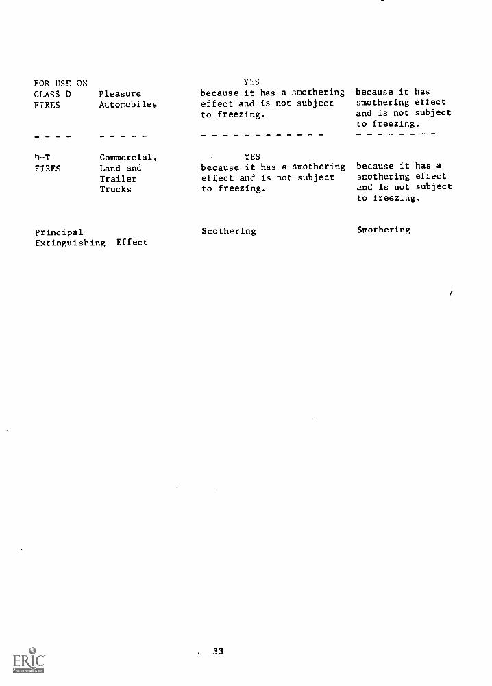
FOR USE ONCLASS DFIRES
D-TFIRES
PleasureAutomobiles
Commercial,Land andTrailerTrucks
YESbecause it has a smotheringeffect and is not subjectto freezing.
YESbecause it has a smotheringeffect and is not subjectto freezing.
because it hassmothering effectand is not subjectto freezing.
because it has asmothering effectand is not subjectto freezing.
Principal Smothering Smothering
Extinguishing Effect
33
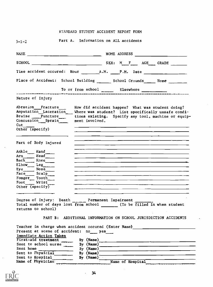
3-1-2
STANDARD STUDENT ACCIDENT REPORT FORM
Part A. Information on ALL accidents
NM
SCHOOL
Time accident occured: Hour
Place of Accident: School Building
To or from school
HOME ADDRESS
SEX: M F AGE GRADE
A.M. P.M. Date
School Grounds
Elsewhere
Home
Nature of Injury
Abrasion FractureAmputation LacerationBruise PunctureConcussion SprainCutOther (specify)
Part of Body Injured
AnkleArmBackElbowEyeFace
HandHeadKneeLegNoseScalp
Fomger_ ToothFoot WristOther (specify)
How did accident happen? What was student doing?Where was student? List specifically unsafe condi-tions existing. Specify any tool, machine or equip-ment involved.
Degree of Injury: Death Permanent ImpairmentTotal number of days lost from school (To be filled in when studentreturns to school)
PART B: ADDITIONAL INFORMATION ON SCHOOL JURISDICTION ACCIDENTS
Teacher in charge when accident occured (Enter Name)Present at scene of accident: no yesImmediate Action TakenFirst-aid treetment By (Name)Sent to school nurse By (Name)Sent home By (Name)Sent to Physicial By (Name)Sent to Hospital By (Name).Name of Physician Name of Hospital

Was a parent or other indivijual notified? No
Name of individual notified:
LOCATION
Athletic fieldAuditoriumClassroomCorridorDressing RoomGymnasiumHome Econ.LaboratoriesSch. GroundsShop
ShowersStairsOthers
Yes When How
SPECIFY ACTIVITY REMARKS
What recommendations doyou have for preventingother accidents of thistype?
Signed: Principal:
Teacher:
35
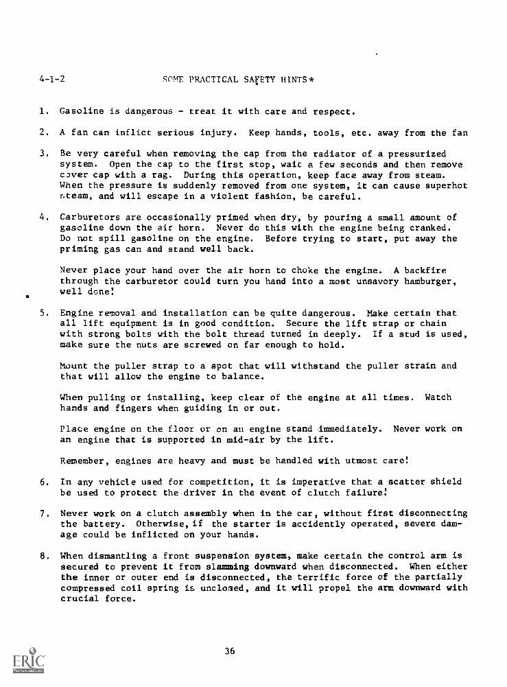
4-1-2 SOME PRACTICAL SAFETY HINTS*
1. Gasoline is dangerous - treat it with care and respect.
2. A fan can inflict serious injury. Keep hands, tools, etc. away from the fan
3. Be very careful when removing the cap from the radiator of a pressurizedsystem. Open the cap to the first stop, wait a few seconds and then removec3ver cap with a rag. During this operation, keep face away from steam.When the pressure is suddenly removed from one system, it can cause superhotsteam, and will escape in a violent fashion, be careful.
4. Carburetors are occasionally primed when dry, by pouring a small amount ofgasoline down the air horn. Never do this with the engine being cranked.Do not spill gasoline on the engine. Before trying to start, put away thepriming gas can and stand well back.
Never place your hand over the air horn to choke the engine. A backfirethrough the carburetor could turn you hand into a most unsavory hamburger,well done!
5. Engine removal and installation can be quite dangerous. Make certain thatall lift equipment is in good condition. Secure the lift strap or chainwith strong bolts with the bolt thread turned in deeply. If a stud is used,make sure the nuts are screwed on far enough to hold.
Mount the puller strap to a spot that will withstand the puller strain andthat will allow the engine to balance.
When pulling or installing, keep clear of the engine at all times. Watchhands and fingers when guiding in or out.
Place engine on the floor or on au engine stand immediately. Never work onan engine that is supported in mid-air by the lift.
Remember, engines are heavy and must be handled with utmost care!
6. In any vehicle used for competition, it is imperative that a scatter shieldbe used to protect the driver in the event of clutch failure!
7. Never work on a clutch assembly when in the car, without first disconnectingthe battery. Otherwise, if the starter is accidently operated, severe dam-age could be inflicted on your hands.
8. When dismantling a front suspension system, make certain the control arm issecured to prevent it from slamming downward when disconnected. When eitherthe inner or outer end is disconnected, the terrific force of the partiallycompressed coil spring is unclo3ed, and it will propel the arm downward withcrucial force.
36
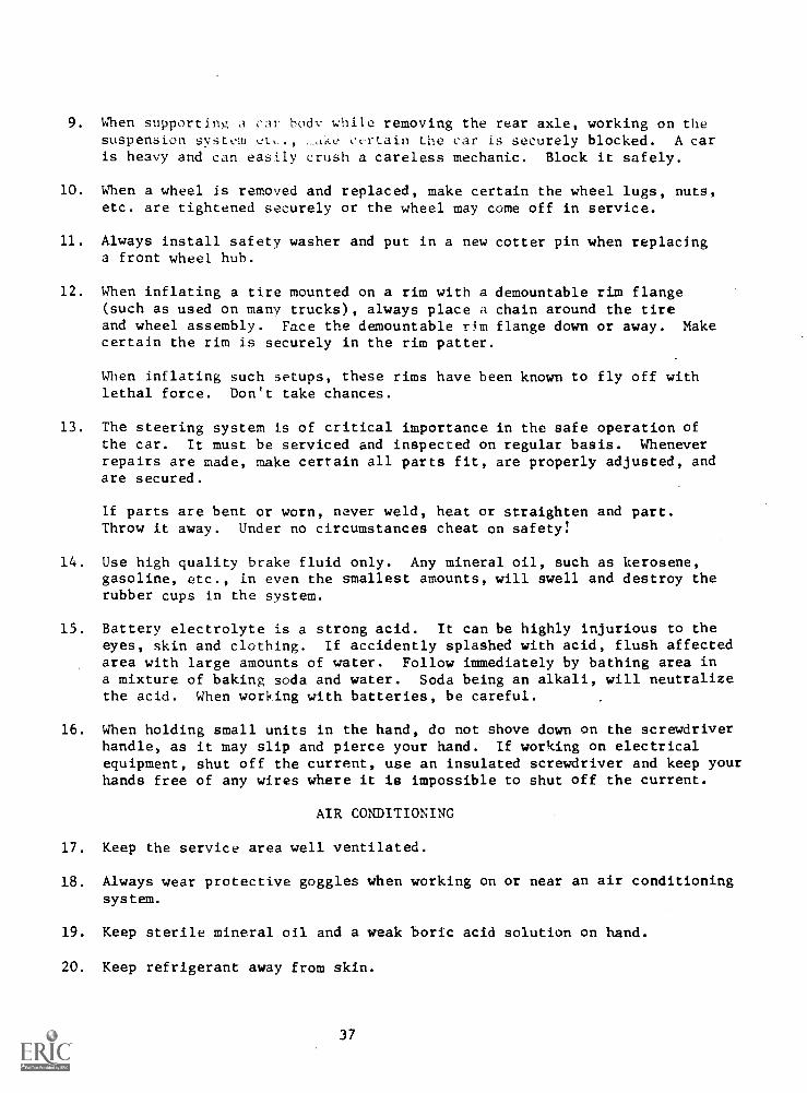
9. When supporting, a car body while removing the rear axle, working on thesuspension system ct., Ake certain the car is securely blocked. A caris heavy and can easily crush a careless mechanic. Block it safely.
10. When a wheel is removed and replaced, make certain the wheel lugs, nuts,etc. are tightened securely or the wheel may come off in service.
11. Always install safety washer and put in a new cotter pin when replacinga front wheel hub.
12. When inflating a tire mounted on a rim with a demountable rim flange(such as used on many trucks), always place a chain around the tireand wheel assembly. Face the demountable rim flange down or away. Makecertain the rim is securely in the rim patter.
When inflating such setups, these rims have been known to fly off withlethal force. Don't take chances.
13. The steering system is of critical importance in the safe operation ofthe car. It must be serviced and inspected on regular basis. Wheneverrepairs are made, make certain all parts fit, are properly adjusted, andare secured.
If parts are bent or worn, never weld, heat or straighten and part.Throw it away. Under no circumstances cheat on safety!
14. Use high quality brake fluid only. Any mineral oil, such as kerosene,gasoline, etc., in even the smallest amounts, will swell and destroy therubber cups in the system.
15. Battery electrolyte is a strong acid. It can be highly injurious to theeyes, skin and clothing. If accidently splashed with acid, flush affectedarea with large amounts of water. Follow immediately by bathing area ina mixture of baking soda and water. Soda being an alkali, will neutralizethe acid. When working with batteries, be careful.
16. When holding small units in the hand, do not shove down on the screwdriverhandle, as it may slip and pierce your hand. If working on electricalequipment, shut off the current, use an insulated screwdriver and keep yourhands free of any wires where it is impossible to shut off the current.
AIR CONDITIONING
17. Keep the service area well ventilated.
18. Always wear protective goggles when working on or near an air conditioningsystem.
19. Keep sterile mineral oil and a weak boric acid solution on hand.
20. Keep refrigerant away from skin.
37
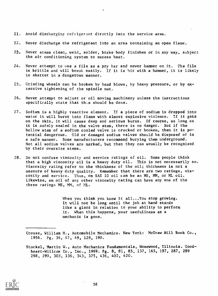
21. Avoid discharging refrigerant directly into the service area.
22. Never discharge the refrigerant into an area containing an open flame.
23. Never steam clean, weld, solder, brake body finishes or in any way, subjectthe air conditioning system to excess heat.
24. Never attempt to use a file as a pry bar and never hammer on it. The fileis brittle and will break. easily. If it is hit with a hammer, it is likelyto shatter in a dangerous manner.
25. Grinding wheels can be broken by head blows, by heavy pressure, or by ex-cessive tightening of the spindle nut.
26. Never attempt to adjust or oil moving machinery unless the instructionsspecifically state that th:.s should be done.
27. Sodium is a highly reactive element. If a piece of sodium is dropped intowater it will burst into flame with almost explosive violence. If it getson the skin, it will cause deep and serious burns. Of course, as long asit is safely sealed in the valve stem, there is no danger. But if thehollow stem of a sodium cooled valve is cracked or broken, then it is po-tential dangerous. Old or damaged sodium valves should be disposed of ina safe manner. Some manufacturers recommend burying them underground.Not all sodium valves are marked, but then they can usually be recognizedby their oversize stems.
28. Do not confuse viscosity and service ratings of oil. Some people thinkthat a high viscosity oil is a heavy duty oil. This is not necessarily so.Viscosity rating refer to the thickness of the oil; thickness is not ameasure of heavy duty quality. Remember that there are two ratings, vis-cosity and service. Thus, on SAE 10 oil can be an MS, MM, or ML oil.Likewise, an oil of any other viscosity rating can have any one of thethree ratings MS, MM, of ML.
When you think you know it all...You stop growing.It will not be long until the job at hand standslike a giant in relation to your ability to performit. When this happens, your usefullness as amechanic is gone.
Crouse, William H., Automobile Mechanics. New York: McGraw Hill Book Co.,
1956. Pg. 36, 47, 49, 128, 190.
Stockel, Martin W., Auto Mechanics Fundamentals, Homewood, Illinois. Good-heart-Willcox Co., Inc., 1969. Pg. 8, 81, 85, 137, 165, 197, 287, 289298, 299, 303, 336, 343, 375, 436, 402, 420.
38
4-1-3 DETAILED DUTIES OF STUDENT PERSONNEL OFFICERS
The purpose of setting forth the duties of the various student personnelofficers is to: (1) conserve time, (2) to give the students an opportunityto serve in positions of responsibility, (3) to simulate a realistic indus-trial personnel organization, (4) to keep the shop or laboratory clean, or-derly, and in good working condition conducive to good learning situations.The officers in this student personnel organization will consist of:(1) a General Superintendent, (2) a Recording Clerk, (3) a Tool Checker, and(4) a Safety Foreman.
GENERAL SUPERINTENDENT
Duties:
(1) Serve as an assistant to the instructor.
(2) General Supervision over the other officers and other members of theclass.
(3) Change the Assignment Responsibility Clean-Up Chart at each desig-nated period
(4) Preside at Grievance Committee hearings.
(5) Confer with Instructor on matters pertaining to the welfare of theclass.
(6) Act as receptionist to greet visitors to the shop.
SUGGESTED CLASS ROUTINE OF GENERAL SUPERINTENDENT
(1) Rotate the responsibility of Assignment Clean-up Chart at a timedesignated by the Instructor.
(2) Explain the duties from the chart to all students so that all studentsunderstand their assignment and the purpose of that assignment.
(3) Call the class to order when the students have arrived in the labora-tory at the beginning of each class meeting.
(4) Have the Recording Clerk check the roll and make the record of atten-dance according to the school policy and that of the Instructor. Ifthe Recording Clerk is absent, the General Superintendent himselfwill perform the Recording Clerk's duties.
(5) Assist the Instructor by having tools and machines easily accessiblefor demonstrations, shop talks, discussion, etc.
39
(6) Work on own project until designated time for clean-up.
(7) Notify class that is is five minutes before time for dismissal bysignaling with the buzzer.
(8) See that clean-up procedures are begun.
(9) Check on the final general clean-up of the laboratory by observa-tion and call the class to attention for any possible last minuteannouncements.
(10) Dismiss the class in accordance with the policy of the Instructor.
RECORDING CLERKDUTIES:
(1) Check the roll at the beginning of each class period and recordabsences on the proper forms.Note: Tardiness is treated as an absence. Records of attendance
will not be changed after the original check.
(2) Assist the Instructor in keeping the Progress chart up to date.
(3) Collect notebooks, reports, and other related materials when theyare due.
(4) Notify the General Superintendent of those members absent so thattemporary appointments for the day can be made to take care of theabsent members' clean-up responsibility.
(5) Assist the Instructor in issuing instruction sheets and other pass-out materials.
(6) Work on own project until the end of the class period or until calledupon for further duties by the General Superintendent or the In-structor.
TOOL CHECKERDUTIES:
(1) Check tool panels and storage areas to see that all tools are intheir proper places at the beginning of the class period.
(2) Check toolS' to see that they are in proper working conditions; forinstance, check for broken handles, loose handles, chipped cuttingedges, broken blades, etc.
(3) Check tool panels and storage areas at the close of the period tosee that all tools have been returned to their proper places.
40
(4) Report to General Superintendent any tools which become dama&,edand/or misplaced.
(5) Make minor repairs and adjustments on tools during the class periodas called upon to do so.
(6) Assist Instructor in checking out special tools and equipment fromthe supply room storage area. See that all such tools and equip-ment are returned to those special storage areas at the end of theclass hour.
(7) When the clean-up signal is given, put away own work and proceedwith the responsibility of seeing that all other students returntools and equipment to their proper storage.
SAFETY FOREMANDUTIES:
(1) See that the laboratory is lighted.
(2) Regulate ventilation.
(3) Control exhaust system.
(4) Study and learn fire drill regulations.
(5) Check fire extinguishers.
(6) Check first aid kit.
(7) Handle safety posters.
(8) Enforce laboratory rules pertaining to general shop safety.
(9) Report all accidents to Instructor immediately.
(10) In case of an accident, fill out necessary accident report forms.(see instructor)
(11) See that all students wear shop approns.
(12) See that all ines are properly guarded.
(13) Inspect the finishing area at the close of each class period. Seethat all cants and containers are properly closed, and all oily ragsand papers are disposed of in a closed metal container.
(14) See that students refrain from throwing debris on the floor inaisles and passageways.
41
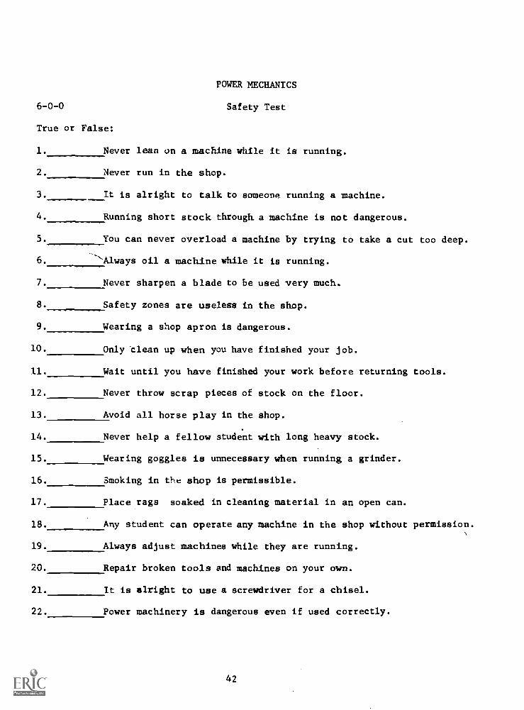
POWER MECHANICS
6-0-0 Safety Test
True or False:
1. Never lean on a machine while it is running.
2. Never run in the shop.
3. It is alright to talk to someone running a machine.
4. Running short stock through. a machine is not dangerous.
5. You can never overload a machine by trying to take a cut too deep.
6. 'Always oil a machine while it is running.
7. Never sharpen a blade to be used very much.
8. Safety zones are useless in the shop.
9. Wearing a shop apron is dangerous.
10. Only clean up when you have finished your job.
11. Wait until you have finished your work before returning tools.
12. Never throw scrap pieces of stock on the floor.
13. Avoid all horse play in the shop.
14. Never help a fellow student with long heavy stock.
15. Wearing goggles is unnecessary when running a grinder.
16. Smoking in the shop is permissible.
17. Place rags soaked in cleaning material in an open can.
18. Any student can operate any machine in the shop without permission.
19. Always adjust machines while they are running.
20. Repair broken tools and machines on your own.
21. It is alright to use a screwdriver for a chisel.
22. Power machinery is dangerous even if used correctly.
42
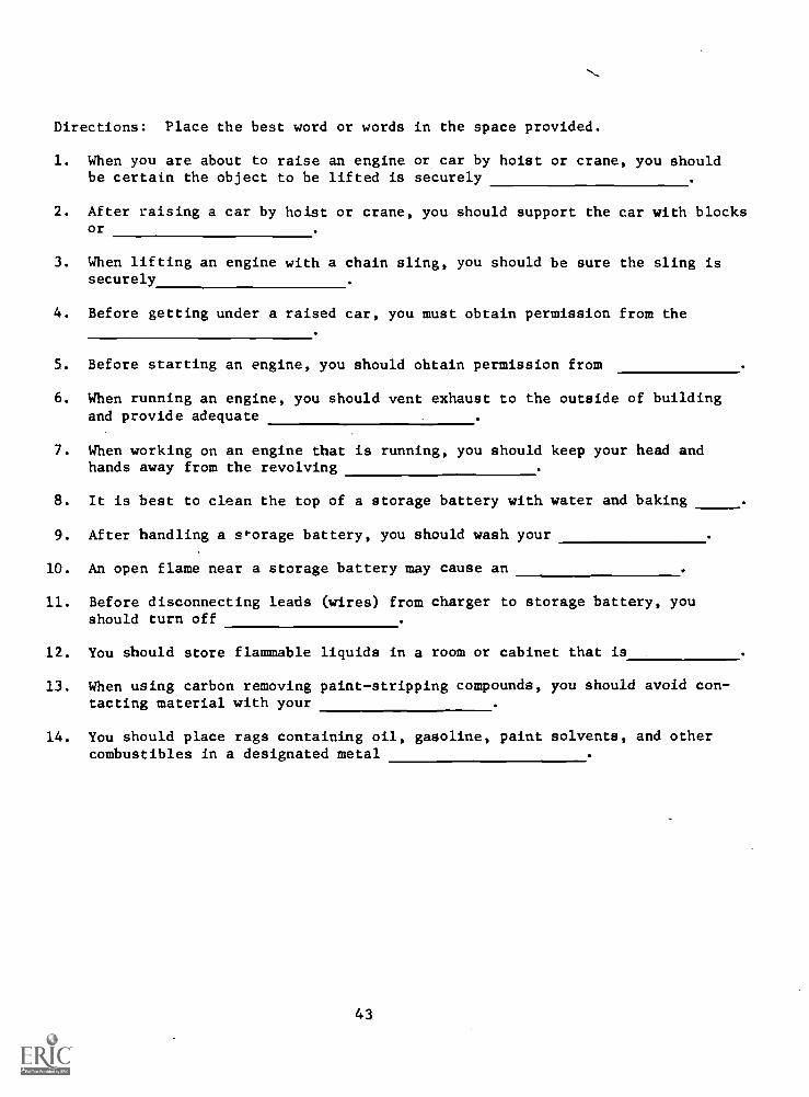
Directions: Place the best word or words in the space provided.
1. When you are about to raise an engine or car by hoist or crane, you shouldbe certain the object to be lifted is securely
2. After raising a car by hoist or crane, you should support the car with blocksor
3. When lifting an engine with a chain sling, you should be sure the sling issecurely
4. Before getting under a raised car, you must obtain permission from the
5. Before starting an engine, you should obtain permission from
6. When running an engine, you should vent exhaust to the outside of buildingand provide adequate
7. When working on an engine that is running, you should keep your head andhands away from the revolving
8. It is best to clean the top of a storage battery with water and baking .
9. After handling a storage battery, you should wash your
10. An open flame near a storage battery may cause an
11. Before disconnecting leads (wires) from charger to storage battery, youshould turn off
12. You should store flammable liquids in a room or cabinet that is
13. When using carbon removing paint-stripping compounds, you should avoid con-tacting material with your
14. You should place rags containing oil, gasoline, paint solvents, and othercombustibles in a designated metal
43
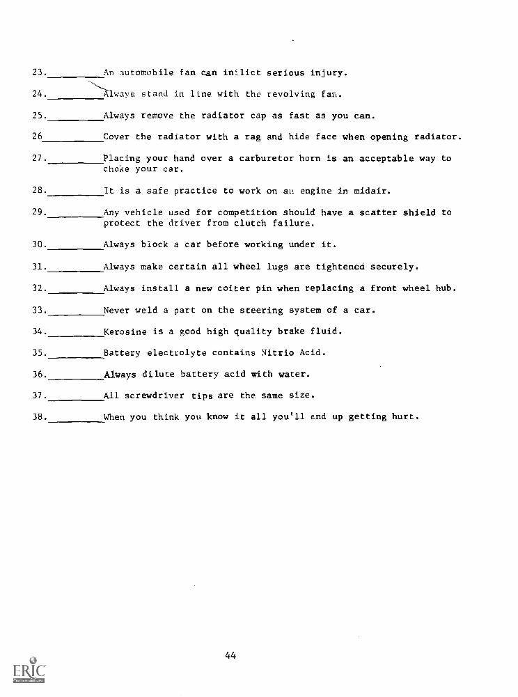
23. An automobile fan can inflict serious injury.
24. Always stand in line with the revolving fan.
25. Always remove the radiator cap as fast as you can.
26 Cover the radiator with a rag and hide face when opening radiator.
27. Placing your hand over a carburetor horn is an acceptable way tochoke your car.
28. It is a safe practice to work on au engine in midair.
29. Any vehicle used for competition should have a scatter shield toprotect the driver from clutch failure.
30. Always block a car before working under it.
31. Always make certain all wheel lugs are tightened securely.
32. Always install a new coiter pin when replacing a front wheel hub.
33.
34.
35.
36.
Never weld a part on the steering system of a car.
Kerosine is a good high quality brake fluid.
Battery electrolyte contains Nitrio Acid.
Always dilute battery acid with water.
37. All screwdriver tips are the same size.
38. When you think you know it all you'll end up getting hurt.
44
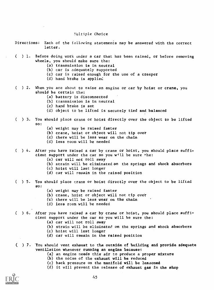
Multiple Choice
Directions: Each of the following statements may be answered with the correctletter.
( ) 1.
( ) 2.
( ) 3.
( ) 4.
( ) 5.
( ) 6.
( ) 7.
Before doing work under a car that has been raised, or before removingwheels, you should make sure the:
(a) transmission is in neutral(b) car is adequately supported(c) car is raised enough for the use of a creeper(d) hand brake is applied
When you are about to raise an engine or car by hoist or crane, youshould be certain the:
(a) battery is disconnected(b) transmission is in neutral(c) hand brake is set(d) object to be lifted is securely tied and balanced
You should place crane or hoist directly over the object to be liftedso:
(a) weight may be raised faster(b) crane, hoist or object will not tip over(c) there will be less wear on the chain(d) less room will be needed
After you have raised a car by crane or hoist, you should place suffi-cient support under the car so you will be sure the:
(a) car will not roll away(b) strain will be eliminated on the springs and shock absorbers(c) hoist will last longer(d) car will remain in the raised position
You should vent exhaust to the outside of building and provide adequateventilation whenever running an engine because:
(a) an engine needs this air to produce a proper mixture(b) the noise of the exhaust will be reduced(c) back pressure on the manifold will be lessoned(d) it will prevent the release of exhaust gas in the shop
45
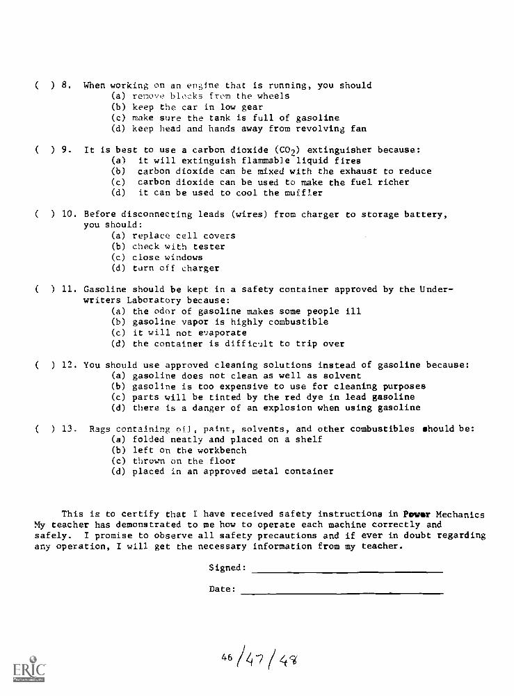
( ) 8. When working on an engine that is running, you should(a) remove blocks from the wheels(b) keep the car in low gear(c) make sure the tank is full of gasoline(d) keep head and hands away from revolving fan
( ) 9. It is best to use a carbon dioxide (CO2) extinguisher because:(a) it will extinguish flammable liquid fires(b) carbon dioxide can be mixed with the exhaust to reduce(c) carbon dioxide can be used to make the fuel richer(d) it can be used to cool the muffler
( ) 10. Before disconnecting leads (wires) from charger to storage battery,you should:
(a) replace cell covers(b) check with tester(c) close windows(d) turn off charger
( ) 11. Gasoline should be kept in a safety container approved by the Under-writers Laboratory because:
(a) the odor of gasoline makes some people ill(b) gasoline vapor is highly combustible(c) it will not evaporate(d) the container is difficult to trip over
( ) 12. You should use approved cleaning solutions instead of gasoline because:(a) gasoline does not clean as well as solvent(b) gasoline is too expensive to use for cleaning purposes(c) parts will be tinted by the red dye in lead gasoline(d) there is a danger of an explosion when using gasoline
( ) 13. Rags containing oils paint, solvents, and other combustibles should be:(a) folded neatly and placed on a shelf(b) left on the workbench(c) thrown on the floor(d) placed in an approved metal container
This is to certify that I have received safety instructions in Power MechanicsMy teacher has demonstrated to me how to operate each machine correctly andsafely. I promise to observe all safety precautions and if ever in doubt regardingany operation, I will get the necessary information from my teacher.
Signed:
Date:
46 /4 -2 / 47

UNIT III
TOOLS AND THEIR FUNCTIONS
1-0-0 At the end of the job, the students will apply their knowledge ofhand tools by scoring 70% on a teadher-made test.
1-1-0 For 45 minutes, the project teacher will lecture and demonstratethe use and types of hand tools.
1-1-1 Students will use socket set, V drive for heavy work.1-1-2 Use socket set - 3/4' drive on small engine disassembling.1-1-3 Discuss combination open-end and box-end wrenches and their
uses.
1-1-4 Discuss torque. Tighten to specification.1-1-5 The students will use open-end wrenches on both automobile
engine and small engines.1-1-6 Students will use the different types of wrenches after dem-
onstration.
1-2-0 The project teacher will lecture and demonstrate the care andsafety of hand tools.
1-2-1 Have students clean hand tools.1-2-2 The student will find the proper tool for a specific job.1-2-3 Require the student to use a greasy tool and compare its
use to a clean tool.1-2-4 Show film, Safety on Hand Tools.1-2-5 Handout.
2-0-0 At the end of the job, students will apply their knowledge of fast-eners by scoring 70% on a teacher-made test.
2-1-0 The project teacher will use automotive mechanics referencebooks to teach the knowledge of fasteners and their relationshipto each other for 45 minutes as monitored by the projectmonitoring system.
2-1 -1 Define fasteners.2-1-2 The student will list different types of nuts, screws, bolts,
and studs. (Handout 2-1-2)2-1-3 Students will be required to know the different thread classes
found on nuts and bolts.2-1-4 Students will study the various types of screwheads.2-1-5 Students will study the various lock washers and their functions.
(Handout 2-1-5 and 2-1-5a)2-1-6 Students will study the use of rivets and list types.
(Handout 2-1-6)
4c(( 50
3-0-0 At the end of the job, the students will apply their knowledge oftest equipment by scoring 80% on a teacher-made test.
3-1-0 The project teacher will use the operating instructions manualfor 90 minutes in teaching the students the use of test equip-ment, such as the King electronic engine tester timing light, pp.29, Dwell Meter pp. 23, Idle tcst, alternator, Diode starter test,as monitored by the project monitoring system.
3-1-1 Read preparation for test and general function of King tester.3-1-2 Place A.C. switch in on position.3-1-3 Have students learn to plug the A.C. cord to the proper outlet.3-1-4 Read function of King Scope.
A. Perform preliminary adjustments to the controls of KingScope as outlined in manual.
B. Set pattern selector to do play position.
C. Set pattern selector to secondary position.3-1-5 Have students to study the Tachometer.
A. Set engine cycle selector to appropriate position severaltimes.
B. Turn engine R.P.M. selector to 1000RPM.
C. Read related references.3-1-6 Show students how to connect timing light and aim at proper
place.3-1-7 Require students to locate timing mark and pointer.3-1-8 Have students to practice rotating distributor.3-1-9 Study Dwell meter operation.
A. Dwell meter consists of four scales.
B. Three of the scales are divided in degrees to indicate4, 6, 8 cylinder dwell.
C. Study the 4th scale which ranges from Q - 100 percent andindicates a corresponding percent of dwell. See dwellscale on machine.
3-1-10 Study the combustion meter.3-1-11 Have students read the combustion from several engines or
cylinders.3-1-12 Have students study use and care of combustion tester such as:
A. A combustion tester is a precision instrument.
B. Never use the combination tester on an engine while gumsolvents or oils are being introduced into combustionchamber through the carburetor.
C. Do not use combustion tester on an engine that is burningoil badly. (Handout 3-1-12)
51
4-0-0 At the end of the job, the students will apply their knowledge ofspecialty and machine tools by scoring 707, on a teacher-made test.
4-1-0 The project teacher will provide activities in the use and care ofthe valve conditioning machine for 105 minutes, as monitored bythe monitoring form.
4-1-1 Have students to write a report on valve-refacing machine. (ref4-i-2 Have student to learn the following valve seat grinding operations.
A. Use a k" drill for driving wire carbon cleaningbrushes in removing carbon from the engine blockand cylinder heads.
B. To sharpen carbon brushes grind the wire ends squareby holding the brush in an electric drill with the brushrevolving against a running grinding wheel.
C. Inserting the pilot after the proper size pilot for the valveguide has been selected, the tapered sleeve on this pilotshould be run out on its tread as far as possible. Theninsert this pilot until its upper taper stops on the valveguide.
4-1-3 Install stone and sleeve on pilot.A. Select stone in correct size.
B. Screw the stone tightly against collar of the sleeve.
C. Adjust the arm of the dressing stand so the angle dressedon the stone corresponds to the angle ground on the valve face.
4-1-4 Grind the valve seat.A. While grinding support driver lightly to allow its vibrating
mechanic to operate freely.
4-2-0 The project teacher will provide activities on the use and functionof the Distributor Tester for 45 minutes as monitored by projectmonitoring system.
4-2-1 Mounting Distributor Operations
A. Standard Stationary distributors are mounted in V-Clamp
B. Rotating type distributors, require a bushing adapter tofunction properly. Insert correct accessory bushing adapterin V-Clamp and place distributor in bushing.
C. Use slotted bracket to support vacuum control in properposition to allow distributor to rotate freely on vacuumadvance.
D. Mount distributor in V-Clamp and lower shaft into chuck.Clamp distributor shaft firmly in chuck and align clampin center position. Rotate disc by hand until Clamp'sproperly centered and disc rotates freely.
52

4-2-2 Review preliminary test instructions.A. Both speed control and test selector switch must be in off
position.
B. Connect tester line cord to AC outlet.
C. Caution: do not operate motor without a distributor mountedin chuck.
D. Mount distributor V-Clamp and secure shaft firmly inchuck jaws.
E. Connect test lead to distributor insulated point terminaland bare Grd. Clip to distributor body at a good cleansurface area.
4-2-3 Refer to activity sheets for point resistance test, condensertest, general test information.
4-3-0 The project teacher will demonstrate and provide activities onthe use of the Headlight Tester.
4-3-1 Students will study the Four--Headlight System.4-3-2 Require the students to follow the operating instruction manual
for Headlight tester.
4-4-0 The project teacher will give instructions for 90 minutes on theoperations and functions of the Alternator - Regulator - Battery -Starter - Tester.
4-4-1 Require the students to study and practice the Battery Capacitytest.
4-4-2 Students will study the Starter Draw Test procedures and performthe procedures on the tester.
4-4-3 Have the students to crank engine for 5 seconds while notingstarter draw on 500 AMPS scale, and cranking voltage on 20volts scale.
4-4-4 List safety precautions to follow when using tester.4-4-5 Measure the amps from several batteries with a load.4-4-6 Secure 3 alternators and 3 starters and test.
4-5-0 The project teacher will demonstrate the use of the battery charger.
4-5-1 Have the students to learn the proper way of connecting thecharger to the battery.
4-5-2 Require the students to learn the function of all control knobs.4-5-3 Study the slow charging procedures and the fast charging procedures.4-5-4 The students will study and follow operating Guide Model 32-134
for battery charger to be handed out by teacher.4-5-5 Unit test.
1-2-5
STUDY QUESTIONS
TOOLS AND THEIR FUNCTION
1. What wrench is used to tighten nuts and bolts to specification?
2. Why should you keep your tools clean?
3. Name two types of screwdrivers.
4. What kind of hammer should the mechanic use?
5. If you had a box-end wrench with 9/16 on one end, what could bethe other sizes?
6. List three types of wrenches.
7. Can a ratchet handle be used on the combination open and box-endwrench?
8. What tool is used to measure the engine cylinder?
9. What machine is used to completely analyze the car?
10. Define the following words or terms:
A. Primary G. RPM
B. Secondary H. Ballast
C. Polarity I. Dwell
D. KV J. TDC
E. Ground K. BDC
F. Lobe
11. Explain how to put number one (1) piston on T.D.C.
12. List the procedure used in testing the alternator.
55
2-1-2
HAND TOOLS
Nuts, Screws, Bolts, and Studs
In the correct column below, list the various types of nuts, screws,bolts, and studs.
Nuts Screws Bolts Studs
56
2-1-5
HAND TOOLS
Fasteners
Study the various fasteners. In the first column list the name ofeach one. In the second column list the funtion of each.
Hand Tool Function
57
2-1-5a
HAND TOOLS
Lock Washers
Below is a list of the various lock washers. After each, write its function.
1. Plain---
2. External-- -
3. Internal---
4. External-Internal---
58
2-1-6
HAND TOOLS
Rivets
In the columns below, list the name of each rivet. In the secondcolumn, name the use.
Rivets Use
59
Test Equipment
Read the combustion from several engines or cylinders. Record your find-
ing below:
4.
Engine
60
Readings
4-5-5
TEST ON TOOLS AND THEIR FUNCTIONS
1. List five types of wrenches.
A. C. E.
B. D.
2. Name three handles that could be used with a socket wrench.
A. B. C.
3. What tool is used with the socket and ratchet to get to nutsand bolts in close places?
4. What tool is used to measure the cylinder bore?
5. What kind of washer would you use with a nut and bolt to lock the nut?
6. Is it possible to check the alternator with the King electronic tester?
7. What is the dwell meter used for?
8. What is the scientific name for the timing light?
9. Name the instrument you should use in testing a battery?
10. What tools are used to remove a broken head bolt from the engine block?
11. What are feeler gauges?
12. Describe the procedure of measuring a shaft with an outside caliper.
13. Name the important things to do in taking care of tools.
1.
2.
3.
14. What machine is used to reface the valve seat?
15. List the four parts of the machine that answer No. 14.
A. C.
B. D.
61 z 4

UNIT IV
PREVENTIVE MAINTENANCE
1:0-0 At the end of the job, the students will apply their knowledge ofdraining and refilling the crankcase with a 1007. accuracyusing the factories standards.
1-1-0 The project teacher will provide activities on draining andrefilling the crankcase with oil for 25 minutes as monitoredby the project monitoring system.
1-1-1 Warm up engine and then cut off ignition switch.1-1-2 Raise car and secure on stands or lifts.1-1-3 Drain crankcase oil in drain pan or can.1-1-4 Replace drain plug securely and refill crankcase to proper
level.1-1-5 Clean up work station.1-1-6 Have instructor check completed job.1-1-7 Answer questions on draining and refilling crankcase
(Handout 1-1-7)
1-2-0 The project teacher will provide activities on removing andreplacing elements in oil filters for 50 minutes as monitoredby a monitoring system.
1-2-1 Place a pan or can under filter and remove drain plug.1-2-2 Loosen cap screw or cover nut.1-2-3 Remove cover and gasket.1-2-4 Remove filter elements and seal (if any)1-2-5 Wipe the inside of the case clean.1-2-6 Replace and tighten the drain.1-2-7 Install the bottom oil seal inside the filter case if used.1-2-8 Replace filter element by pushing it slowly over the center
tube.
1-2-9 Replace top seal if used and cover, using a new gasket.Tighten cap screw securely.
1-2-10 Run engine ten minutes.1-2-11 Check oil to crankcase.1-2-12 Add oil to crankcase.1-2-13 Check flexible oil lines and report their condition to
instructor.
65
1-2-14 Have instructor check complete job. (Handout 1-2-14)
1-3-0 The project teacher will provide activities on lubricatingautomobiles for 50 minutes, as monitored by the projectmonitoring system.
1-3-1 Place car in position on lift. Do not raise lift until itis checked by instructor.
1-3-2 Open hood and cover fenders.1-3-3 Lubricate components under the hood that use motor oil.1-3-4 Check engine oil.1-3-5 Clean and oil crankcase ventilator.1-3-6 Clean and inspect air filter or cleaner.1-3-7 Lubricate steering gear. For power steering, refer to
manual.1-3-8 Lubricate upper control arms. (Note: some cars have plugs
that must be moved.)1-3-9 Check water level in battery.1-3-10 Raise car with lift.1-3-11 Clean fittings and lubricate front-end suspension and steer-
ing connections.1-3-12 Lubricate clutch and brake pedal bushings, lubricate uni-
versal joint, check differentials, and refer to manufacturer'smanual for proper check of transmission fluid. (Reportto instructor)
1-3-13 Let instructor check your completed job.1-3-14 Lower lift and remove car.1-3-15 Clean up work station.1-3-16 Answer questions on lubricating an automobile. (Handout
1-3-16)
1-4-0 The project teacher will provide activities on removing,lubricating, and adjusting front wheel bearing for 50minutes as monitored by monitoring system.
1-4-1 Look up the different types of wheel bearings.1-4-2 Jack up car and secure it on stands.1-4-3 Remove carter pin, adjusting nut, washer and outer
bearing.1-4-4 Remove front hub caps.1-4-5 Remove wheel by pulling straight out to prevent damage
to the grease seal.1-4-6 Remove the grease seal and inner bearing. Wash all
parts thoroughly in cleaning solvent and dry.1-4-7 Check all bearings for cracked bearing cases, worn, pitted
balls or rollers.1-4-8 Check for cracked or rough inner and outer cups.1-4-9 Pack wheel bearings with wheel bearing grease.1-4-10 Have instructor check at this point.1-4-11 Install inner bearing and grease seal.1-4-12 Put wheel on spindle and install outer bearing washer
and nut.1-4-13 Adjust the bearings by tightening the adjusting washer.
66

r.
and nut whIle rotating the wheel back and forth. (Referto service manual).
1-4-14 Lock the nut with a new carter pin.1-4-15 Have instructor check at this point.1-4-16 Install dust and hub caps.1-4-17 Clean up work station.1-4-18 Lower car to floor.1-4-19 Answer question on removing, lubricating, and ad-
justing front wheel bearing. (Handout 1-4-19)
1-5-0 The project teacher will provide activities on removing andinstalling rear wheel bearings and grease seals for 100minutes as monitored by the project monitoring system.
1-5-1 Jack up car and secure it on stands.1-5-2 Remove hub cap and rear wheel.
Note: Some time you will find retaining nuts. If so, re-move them and then remove the drum.
1-5-3 Use wheel puller to remove drum.1-5-4 Remove real axle (use shaft puller)1-5-5 Remove grease seal (use special tool)1-5-6 Check bearing on axle shaft for looseness. If excessive
looseness is found the bearing has to be replaced.1-5-7 If the bearing needs replacing, nick the lock ring with a
chisel and remove the bearing with a special puller.1-5-8 Soak oil seal in light engine oil for at least one half hour
and then install oil seal in the base of axle housing withlip facing in.
1-5-9 Install bearing and new lock ring on axle shaft and press on.1-5-10 Have instructor check your work at this point.1-5-11 Install axle shaft in housing.1-5-12 Install brake drums and wheel.1-5-13 Lower car to floor.1-5-14 Clean up station.1-5-15 Have instructor check completed job.1-5-16 Remove rear wheel hub caps.1-5-17 Remove carter pin from the axle shaft.1-5-18 Loosen the axle nut.1-5-19 Loosen the nuts or bolts.1-5-20 Jack up the rear wheels and secure on stands.1-5-21 Remove the lug bolts or nuts and wheel.1-5-22 Remove the axle nuts and washer.1-5-23 Install a wheel puller and pull the wheel off rear
brake drum. (If you have a loose brake shoe checkwith your instructor)
1-5-24 Disconnect the brake line, remove the axle drive key.1-5-25 Remove the bolts attaching the brake backing place to
the axle housing and remove the backing plate.1-5-26 Remove the shims from the axle housing and keep to-
gether for reassembling.1-5-27 Remove the axle shaft and bearing with a special puller.
67

1-5-28 I learir are worn er damaged, replacethem.
1 -5 -2Q Remo o se; from the brake backing plate.1-5-20 11.1,ye * :-*1?ck at this point.1-5-31 Clean ..arts and dr',! them.
1-5-32 Soap oil :eal in oil.1-5-33 Pack roar axle bearing with grease (wheel bearing grease)1-5-34 Install the axle 3haft and bearing in axle housing.1-5-35 Install the axle bearing outer cup.1-5-36 Replace axle housing shims in the same position as they were
removed.1-5-37 Install a ncw outer seal in the backing place and install
backin4 plate.1-5-38 Install the bolts attaching the brake backing plate to axle housing
and tighten bolts to specification.1-5-39 Install the axle drive key and the brake drum.1-5-40 Check axle shaft and play and check specification if not with-
in manual for adjustment.1-5-41 Connect the brake line.1-5-42 Install tic axle drive key and the brake drum.1-5-43 Install the axle nut and washer, tighten snug.1-5-44 Place the wheel in place and install lug nut or bolts.1-5-45 Lowor c-r and tighten lug bolts and axle and axle nut to specification.1-5-46 Install cotter pin in axle and replace hub cap.1-5-47 Plve in, tructor check completed job.
Clal a work area.1-5-49 Answer cuestions on removing and installing rear wheel
bearing and grease seals. (Handout 1-5-49)
1-6-0 The acher will provide activities on adding brakefluid tc a (-:11kr for 50 minutes as monitored by theproject mon::ri.7,4 system.
1-6-1 Carfuli .an all dirt and grit from the top of masterclindc.r.
1-6-2 Use ,.:orrt:ct ...Tench size (Never pliers) to remove re-servoir cdp.
1-6-3 Examine c.lp to make certain that baffle is in place andvent '7.cle not clogged. Blow vent hole out with air
1-6-4 Fill until fluid is approximately inch belowr(17, ,f cylinder. Do not over fill.
1-6-5 Replace can certain gasket is in place.
1-7-0 The prolect t "acher will provide activities on installingsealed beam and aim headlights for 50 minutes as monitoredby the project montoring system.
1-7-1 Remove headlamp door rim. Remove the retainingspring from the retainer ring on the light you aregoing to replace.
1-7-2 Remove the head light retaining ring screws. Do notdi::turl-, the adjusting screws.
1-7-3 Remove the retaining ring and pull the light forward anddisconnect the connector ring.
1-7-4 Install new sealed beam and connect it.
68
1-7-5 r:..aining ring.
1-7-6 H.,v.2 intlrc:er check job.1-7-7 , rr r.1 adjust to specifications following
eT:i7mert Tinufacturer's instruction.1 -7 -S If Ilmer is not available, place car 25 feet from aiming
screen en a level and align center line of screen to center
1-7-9 AdiliF,t head vertical aim of each of the single filamentr7, manufacturer's specifications as outlined in shop
manuals.1-7-10 Adjusc tie head light horizontal aim of the single filament
1-7-11 SwitLh Ele lights on the low beam and adjust the two filamentlights t- car manufacturer's specifications.
1-7-12 Have instructor check job.1-7-13 Install the headlight door rim.1-7-14 Clean up work area.1-7-15 Answer questions on installing Sealed Beam and Aim Head-
li4hts (Handout 1-7-15)
1-8-0 The project teacher will provide activities on installingmufflers tail pipes for 50 minutes as monitored by theproject monitoring system.
1-8-1 Lrwen th- climp at front of muffler.1-8-2 Loe ; ^n ti-7i -lamp at the rear of muffler.1 -9 -3 Take tail r:rc! loose at front and rear tail pipe brackets.1-8-4 Remc,e tail pipe from muffler.1-8-5 Remove mxifler from pipe.1-8-6 Cheek and tighten muffler inlet pipe.1 -8 -7 Install muffler assembly on inlet pipe (do not tighten).1-8-8 Install muffler outlet pipe and install front and rear brackets
(do not tighten).1-8-9 Line up tail pipe.1-8-10 Tighten rear tail pipe clamp and clamp bracket.1-8-11 Line up all joints by shaking muffler.1-8-12 Tighten front tail pipe bracket and clamp in this position.1 -8 -13 Tighten front and rear muffler clamps.1 -8 -14 Clean up station.1-8-15 fa-.,. ;nst:;ctor check your job.1-8-16 Anwer qucons on muffler and tail pipe (Handout 1-8-16)
1-9-0 The to:I:her will provide activities on balancing wheelson the 70 minutes, as monitored by the project monitor-ing system.
1-9-1 Clean wheels.1-9-2 Install Model 127 wheel adaptor.1-9-3 Remove hub cap and chrome ring if necessary.1-9-4 Select proper adaptor according to wheel size.1-9-5 Check adaptor to make sure both cam-lever arms are in
unlocked position (indicated by red flags when viewingadaptor from front).
1-9-6 Adjust both diameter adjustment screws if necessary, so thatthe neoprene ring is just barely snug in wheel rim. (do
not turn adjustment screws too tightly.)
69
1-9-7 Swing the two cam-level arms into locked position, bothat the same time, so that the red flags are not visible.
1-9-8 Install 107-A Instrument on adaptor.1-9-9 Mount 107-A Instrument over adaptor by lining up 4 holes in
lock with 4 adaptor studs.1-9-10 Gently press on instrument near lock before closing lock,
and close 4 locks. (Don't force locks)1-9-11 Before spinning:
(a) Remove rocks and gravel from tire tread.(b) Check for dragging brakes and tight wheel bearings.(c) Make sure both adaptor cam-level arms are in locked
position.(d) Make sure all 4 catches on instrument are closed.(e) Pull firmly on adaptor to make sure it is properly
installed on wheel.1-9-12 Spin the wheel while no one is in line with it.1-9-13 Put your instrument back in spinner case (top side up).
1-10-0 The project teacher will provide activities on tune-in for 50minutes as monitored by the project monitoring system.
1-10-1 Jack up front of car at center, both front wheels aboutIA" above floor.
1-10-2 Move your wheel balancing machine to job on car.1-10-3 Spin wheel (using foot pedal) to check for out of balance.1-10-4 Install adaptor and tune in to wheel correclty (read
instructions carefully).1-10-5 At this point, the instructor will demonstrate and ex-
plain the use of the knobs while tuning in.1-10-6 The students will clean up the work station.1-10-7 Answer questions on balancing wheels. (Handout 1-10-7)
1-11-0 The project teacher will provide activities on making minorbrake adjustments for 50 minutes as monitored by the projectmonitoring system.
1-11-1 Obtain manufacturer's repair manual. Check for brake pedalfree play. If necessary, adjust to approximately inch.
1-11-2 Check brake fluid. Add if necessary.1-11-3 Raise car and put shop safety stands in place. Lower car
on stands, making certain that stands are placed solidlyunder frame or axle.
1-11-4 Remove the cover from the adjusting hole and, turning theadjusting wheel to expand the shoes until they drag againstthe drum.
1-11-5 Continue to tighten adjuster until the wheel can not be turnedby hand.
1-11-6 After correct drag is obtained, back off on the adjuster.Screw 12 notches (these specifictions may vary from onevehicle to another). The wheel should now turn free.
1-11-7 Replace adjuster hole cover and proceed to other wheels.1-11-8 Answer question on minor brake adjustments (Handout 1-11-8)
70
1-12-C The nroit,ct te,icher will provide activities on making minorkrat-,c (lockheed), for 50 minutes as monitored
system.
:ain mmi:facturer's repair manual. Check pedal free play.Adji:st i.1 necessary.
Check br7e fluid. Add if necessary.1-12-3 ca'- and correctly place safety stands before starting.1-12-4 :,:ake ad::stments on lockheed brakes. Adjust them by the
f ,:ams. The cam is moved by turning the spring-Jd,Ld it on the rear of the backing plate. There are two
cars to cich wheel.1-12.5 !;..,. :,,41..,,t7ent on front wheel. Turn the cam in the
of forward wheel rotation to lcok wheel. Turn-11e. cam 'n the other direction until no drag is felt. Re-neat the same operation on the other cam.
1-12-6 ke adjustments on the rear wheel brakes. Turn the cam:'n the fcrward brake shoe in the direction of forward wheelrc,tation to lock shoe to drum. Turn against wheel rotation
to drum clearance. Reverse procedure to adjustrelr shoes.
The 111-;0-t acher will provide activities on adjusting parkingrake.s :N,"=nal contraction).
-...c.ifacturer's manual, if available..ar a:1L place on four shop safety stands.P.1:i:ing brakes control l "ver in full release position._..,:tdrer's manual to determine specific adjust-
adjustments, check if the wheels turn only whenis in the released position.
r!ct t,:s.acher will provide activities on adjusting parkingir':orn.-11 type) for 25 minutes as monitored by the project
1-1!1-1 mpnwracturer's manual for unit to be worked on.1-14-2 Jack car in in rear. Place safety stands under axle of
,:7-mc, -Inc make sure that parking brake lever is in fullreleased position.
1-1:4-3 Lc, :-at,' -ac luster.
1-14-4 Loosen lock nut and adjust until absolutely no drag isfelt when turning rear wheels.
1-15-0 The project teacher will provide activities on inspection ofbrake linings and drums for 50 minutes as monitored by theproject monitoring system.
1-15-1 Jack up vehicle and place on stands solidly under frame.Remove all wheels and brake drums. Many times, ifdrums are worn, it will be necessary to back off on thebrake adjuster in order to clear the rim of the drum.
71
1-15-2 Inspect brake lining for wear or cracks. If lining iscracked or worn Ai its original thickness (bonded), itshould be replaced. Any riveted type brake lining shouldbe replaced before it wears down to the rivet heads.
1-15-3 Inspect shoes for foreign materials, such as grease,brake fluid, oil, etc. If shoes are oil or fluid soaked,they should be replaced.
1-15-4 Inspect brake drums for scoring and grooving. Recondition-ing of the drum or replacement is justified only if scoringor grooving is excessive.
1-15-5 Inspect front and rear wheels for oil or grease sealleakage.
1-15-6 Check star wheel adjuster (if equipped) for binding orstripped notches.
1-15-7 Inspect wheel cylinders for leakage by sliding wheel cylinderboots back and observing end of cylinder.
1-15-8 Check all bearing and pivot points for lubrication.1-15-9 Blow dust from drum and brakes with air hose, if no re-
pairs are to be made.1-15-10 Replace wheels and drums. Make minor adjustments and
have instructor inspect completed job.1-15-11 Clean up work station.
1-16-0 The project teacher will provide activities on inspection ofsteel tubing and flexible brake lines for two class periods,as monitored by the project monitoring system.
1-16-1 Check fluid level in master cylinder. Observe area aroundfittings for dampness or signs of leakage.
1-16-2 Slide boot back from rear of master cylinder and checkfor fluid leakage.
1-16-3 Locate and check all brake line connections for leaks.1-16-4 Check all tubing that may come in contact with the frame.
Check these points for rubbing which may weaken tubing.1-16-5 Check flexible brake lines for signs of rot, cracked cover-
ing, twisting, or leakage.1-16-6 Check for leakage around bleeder cocks.1-16-7 Report all defects or faults found in tubings or flexible lines
to your instructor.1-16-8 Clean up work station.1-16-9 Answer questions on inspection of linings and drums (Handout
1-16-9)1-16-10 Evaluation (Handout 1-16-10)
72/23
1-1-7
STUDY QUESTIONS
DRAINING CRANKCASE AND REFILLING
1. Why should old oil be allowed to drain for a time?
2. What precautions must be followed in draining oil from the crankcase?
3. What methods are used to keep the oil in the crankcase free fromdirt and grit?
4. What are some reasons that cause engine oil to be low?
5. What is sludge?
6. Define:
(a) dilute
(b) By-pass
(c) corrode
(d) crankcase
74

1-2-14
STUDY QUESTIONS
ENGINE LUBRICATION
1. Name three ways oil can be lost from the engine.
2. Name and explain the three types of lubrication systems.
3. Name the two types of oil filters used.
4. What are the two most commonly used oil pumps?
5. Explain how the by-pass filter operates.
6. Explain how the full-flow filter operates.
7. What is used in the full -flow filter to secure lubrication even ifthe filter becomes clogged?
8. What purpose does the gasket serve?
9. What is viscosity?
10. How do you repair a stripped oil drain plug?
11. Into what two properties can a viscosity be divided?
12. Why are body and fluidity important in an oil?
13. What effect does temperature have on viscosity?
14. Why is the crankcase ventilated?
15. Where can information be obtained with reference to the frequency ofoil changes and the type of oil to be used?
16. How does oil reduce friction?
17. How does water sludge form?
18. What are the three service ratings of oil for gasoline engines?
19. What would SAE 10W-30 mean?
20. If an oil has this marking on the can, SAE 20W, what would it mean?
21. What is an oil gallery?
75
1-3-16
STUDY QUESTIONS
LUBRICATION OF THE :).:TO13IL17:
1. What precautin s'culd be taken when lubricating an automobile?
2. What part of the ,:u-rnbile should be 1;,ricated first?
3. Name two parts '-hat you would use motor oil to lubricate.
4. How would vou clean the oil crankcase ventilator?
5. What purpose does a lubricant serve?
6. Why is it noces.;ary to clean and oil the crankcase ventilator inletand outlet air cleaners?
7. What procedure ,Thould be used in checking fluid in an automobiletransmission:
8. Wbe:t types of uli an_ used in standard transmission?
9. Is it necessary to check the water in the battery when lubricating inautomobile?
10. Hoy do 7flu differential?
76
1-4-19
STUDY QUESTIONS
REMOVE, LUBRICATE, AND ADJUST FRONT WHEEL BEARING
1. When should all parts be washed and dried?
2. Is wheel bearing grease the sane as other lubricants used in theautomobile?
3. Why is the wheel rotated while adjusting the bearings?
4. What precautions should be taken in removing, lubricating, andadjusting front wheel bearing?
5. A good engine oil has a task, what is it?
6. What is meant by the term friction?
7. What is a frozen bearing?
77
1-5-49
STUDY QUESTIONS
REMOVE AND INSTALL REAR WHEEL BEARINGS AND GREASE SEALS
1. How is the axle shaft held in the axle housing?
2. Does the axle shaft bearing need packing before installing?
3. What kind of defects do you look for to justify wheel or axlebearing replacements?
4. Is it necessary to bleed the brakes after replacing bearings? Why?
5. What tool is used to pull off rear brake drum?
6. What should be done to leather seals before installing them?
78

1-5-15
STUDY QUESTIONS
SEALED BEAM AND AIMED HEADLIGHTS
1. How many light filaments does a sealed beam have?
2. What effect will a broken ground wire tre on a sealed beam light?
3. Why should the #2 lights be set on the low beam?
4. Why should all lights except the light being adjusted be covered?
5. What is provided in each sealed beam frame so the light may beaimed?
6. What takes up the slack when the adjustment is loosened?
7. How far should a sealed beam drop in 25 feet?
8. How far should the sealed beam be from the aiming screen?
9. What is a headlight retaining ring?
10. What is a light filament?
79
1-8-lb
1.R5 AND TA1LF'
1. How can one iort from the rear of a muffler?
2. How cln one rel7
3. Name two type.; ,1
." :r,p,. the bott-
4. What is che purpo,t:: o d ..r.ofier?
7:1f:ler?
5. Could a non-reLici..,n :-fler lead to engin,: overheating?
6. How can a tail pipe being burned out in front of the gas tankcause poor gas milea:;e?
7. What 7,rocedure :h1 used in lining up a m:Iffler and tail pipe?
8. What is the rurce c::
80
1-10-7
STUDY QUESTIONS
BALANCING WHEELS
1. On which side of the wheel should balancing weights be placed?
2. Which should be done first dynamic or static balancing?
3. What is meant by the term static balance?
4. What is meant by the term dynamic balance?
5. Where should the weights be applied on the wheel?
81

1-11-8
STUDY QUESTIONS
MAKING MINOR BRAKE ADJUSTMENTS
1. Explain how to check for brake pedal free play.
2. If brake pedal has to much free play it should be adjusted toapproximately inch.
3. Explain how to adjust brakes according to the specification usedin minor brake adjustments.
4. What is a spring loaded bolt?
5. Self-adjusting brakes will make adjustments when moving backwardor when moving forward?
6. Name three definite characteristics brake fluid must have.
82
1-15-9
STUDY QUESTIONS
INSPECTION OF LININGS AND DRUMS
1. Is it necessary to remove the wheel to inspect the drum?
2. What is a drum?
3. Name two things that you can inspect your brake drum for.
4. What are wheel cylinders used for?
5. Brake lines must be made of
6. What unit is used to keep brake shoes in close contact with the drum?
83
t
1-16-17
TEST
PREVT=E MAINTENANCE
1. T., y o'd nil be allowed to drain for a period of time?
2. List three rzecautions to follow it changing engine oil.
3. What methods should be used to keep the crankcase oil free fromdirt and grit?
4. Does an rrgi ,;Lankcase have ventilators? If yes, wh, type?
5. Define the following:
(a) by-pass
(b) viscosity
(c) sludge
(d)
dilute
Cc) corrode
6. Tr what three wave is oil lost from an engine?
7. Name three types of lubricating systems.
8. Name two types of oil filters.
9. Is it necessary to lubricate the rear spring shackles on a car? Why?
10. Why should you never over-lubricate a generator?
11. What procedure should be used in checking transmission fluid inautomobile Transmissions?
12. Does the engine need to be running to check power steering?
13. What type of oil does a standard transmission use?
14. Are there any differences in wheel bearing grease and otherlubricants used in the automobile?
15. Why rotate the se.eel while adjusting the bearing?
16. What precautions should be taken when you remove, lubricate, and
adjust front wheel bearings?
17. Why should grease be kept away from the brake lining?
18. What type of lubricant should be used on front and rear wheelbearings?
19. What is the difference between seals, packing, and gaskets?
20. How is the axle shaft held in the axle housing?
21. After replacing rear wheel bearings, is it necessary to bleedthe brakes?
22. What defects do you look for to justify wheel or axle bearingreplacements?
23. What is a master cylinder?
24. What happens when a small amount of air enters the brake system?
25. Explain how power brakes work.
26. If brake shoes are oiled or fluid soaked, what should be done?
27. Define fuse.
28. What is a filament?
29. Haw many filaments are there in a tail-light bulb?
30. Haw is the sealed beam unit held in place in the headlight?
31. How far should a sealed beam drop in twenty-five feet?
32. What is the function of a muffler?
33. Name two muffler designs.
34. Explain how burned gases leave the engine.
35. What four components make up the exhaust manifold?
36. Explain the function of the exhaust manifold.
37. What is the function of the resonator?
38. What purpose does the exhaust pipe serve? Tail pipe?
39. What is engine exhaust?
40. Define:
(a) fuel (c) manifold
(b) high oil consumption (d) manifold heat control valve
85 /1 )7?.;
UNIT V
ELECTRICAL SYSTEM
1-0-0 At the end of the job, the students will apply their knowledge of amulti cell battery by scoring 707. or above on a teacher prepared test.
1-1-0 During one class the power mechanics instructor will demonstratecorrect procedure in care and maintenance of a battery as monitored
1-1-1 Discuss the uses of an automobile battery.1-1-2 Demonstrate how a multi cell battery operates.1-1-3 Demonstrate the construction of a battery.1-1-4 Demonstrate how the battery cells are opened.1-1-5 Discuss the method of rating batteries.1-1-6 Stress the danger of sulfuric acid. Explain how the acid is used
for an electrolyte.1-1-7 Discuss the way a battery develops electricity.1-1-8 Handout
1-2-0 Power mechanics instructor during one class will demonstrate properprocedure in measuring ipesigsguyiti of battery acid as monitoredby the prcject monitoring system.
1-2-1 Demonstrate removal of caps consealing cells.1-2-2 Write down specific gravity of the battery.1-2-3 Demonstrate correct method of checking battery for cracks.1-2-4 Demonstrate the cleaning of the anode and cathode.1-2-5 Demonstrate proper water level of each cell.1-2-6 Demonstrate replacement of caps e2curely.1-2-7 Discuss the dangers of tilting a battery.1-2-8 Demonstrate placing hydrometer to .leasure specific gravity.
2-0-0 At the end of the job, the students will apply their knowledge of theoperation of a bolt meter by scoring 70% or above on a teacher-madetest.
2-1-0 The power mechanics instructor during one class will show thestudents correct procedures in using a volt meter as monitored by theproject monitoring system.
2-1-1 Demonstrate correct location of probs.2-1-2 Discuss the uses of a volt meter.2-1-3 Demonstrate the method of reading a volt meter.2-1-4 Discuss the measuring of volts.2-1-5 Discuss relationship of voltage to current.2-1-6 Discuss relationship of voltage to resistance.2-1-7 Discuss the meaning of A. C. current.2-1-8 Discuss the meaning of Do C. current.2-1-9 Discuss the reason for always placing a volt meter in parallel
with a circuit.
89
3-0-0 At the end of ! dent will apply their knowledge of'r iove on a teacher-made test.
3-1-0 Power during three classes will demonstratecorrect pr..,:H! s=bly and disassembly of an automobile A.C.and D.C. , -7 . 1)y project monitoring system.
3-1-1 Discuss 1:3-1-2 DiSC11!7'3 does.3-1-3 Discuss ', t D.C. generator.3-1-4 Demonstr-- L :ion of a ,,-,.prator.3-1-5 Disr.,_,7F- -f A.C. gen. .1 r.
3-1-6 Dem.,rt,- :-:)nstruction.3-1-7 both A.C. and D.C. generators.
3-2-0 Power 77,eci:., during two classes will demonstrate correctprocedure 7.1:1.2-ce and repair of an automobile starter orcranking r:1::.Hr --,.1Lored by the project monitoring system.
3-2-1 Di.cu : principles.3-2-2 Demons,J.L-i. . 'oy disassembling a starter.3-2-3 Demonstr, I -7!.;
3-2-4 . clutch.3-2-5 Discuss , cranking motor control.
3-3-0 Power me,,* during two classes will demonstrate cor-rect -lance and repair of an automobile solenoidas monitore,4 7,7-iect monitoring system.
3-3-1 Disc...is,: --,-,7?pts of the solenoid.3-3-2 Discuss works along with the starter.3-3-3 Discuss am: demonstrate how electricity effects the solenoid
sucking ac:icn.
3-4-0 Power mechanics instructor during two classes will demonstrate cor-rect methcrf operation of a voltage regulator as moni-tored by t,le. ;,.nitoring system.
3-4-1 Discuss . ..f D.C. generators.
3-4-2 Discuss temperature compensation of a voltageregulatr.
3-4-3 Descri'- a 1 .te following:(a) .
(b) with field relay(c) Transisorized voltage regulator with field relay(J) -^;t^.-, regulator
3-5-0 Power mechanic; instructor during one class will instruct studentin theory and operation of an ammeter gauge as monitored by theproject monitc-in p. sYs.tem.
90
3-5-1 Demonstrate3-5-2 Demonstrate3-5-3 Explain the3-5-4 Discuss the3-5-5 Demonstrate
the use of ammeter.where ammeter should be connected in the circuit.reasons for having an ammeter.job the ammeter performs.the reason an ammeter works.
3-6-0 Power mechanics instructor during one class will instruct the studentin the operation of the distributor as monitored by the project moni-toring system.
3-6-1 Discuss the operation of the distributor.3-6-2 Discuss what happens when the points are open.3-6-3 Describe the different types of distributors:
(a) Distributor with contact poilit(b) Distributor with magnetic pickup(c) Distributor with contact point and transistorized system
3-6-4 During one class period have the student draw a diagram ofthe distributor system.
3-7-0 Power mechanics instructor during two classes will instruct thestudent in the design and operation of spark plugs as monitoredby the project monitoring system.
3-7-1 Discuss the basic parts of a spark plug:(a) Metal shell(b) Ground electrode(c) Terminal(d) Resistor(e) She(f) Porcelain insulator(g) Electrode extending through the insulator.
3-7-2 Describe location of spark plug in an automobile.3-7-3 Explain the reason a spark plug does not interfere with your radio.3-7-4 Demonstrate the spark produced by the spark plug.
3-8-0 The power mechanics instructor in two days will instruct the studentsin the theory and operation of a coil as monitored by the projectmonitoring system.
3-8-1 Discuss the purpose of the coil.3-8-2 Describe different types of coils.3-8-3 Discuss the operation of a coil.3-8-4 Demonstrate a magnetic field of a coil.3-8-5 Discuss voltage produced by coils.3-8-6 Demonstrate the flow of electricity from battery through the coil.3-8-7 Answer study questions (handout).
3-9-0 Power mechanics students during two classes will be introduced to thetheory and application of a horn relay in an automobile as monitoredby the project monitoring system.
91
3-9-1 Discuss the purpose of the horn relay coil.3-9-2 Demonstrate the way the relay makes a horn blow.3-9-3 Demonstrate a relay in a new car by opening the door with key in
the ignition.
4-0-0 Administer Unit Test covering Interims 1-4
92/3
INFORMATION SHEET *
Electrical Safety
When installing electrical components, make certain they are properly
fused. Wires must be insulated, kept from hot areas, and must be secured
to prevent chafing. When passing through metal parts, install grommets,
(rubber insulating washers), to protect the wires. Terminals should be
clean and tight.
When working on the electrical system, disconnect the battery to
prevent accidental short circuiting.
Use great care when repairing head lamp circuits. If the lights
suddenly go out, it could be tragic.
Never replace a fuse with a fuse of higher capacity. Never replace
a fuse with a bolt, wire, etc. The fuse, of correct capacity, must be
in the circuit.
*
Stockel, Martin W. Auto Mechanics Fundamentals. Homewood, Illinois:Goodheart-Wilcox Company, Inc., 1969, page 402.
94

1-1-8a
ELECTRICAL SYSTEM
Define the following:
1. Electron Theory
2. Matter
3. Molecule
4'. Atoms
5. Current
6. Voltage - EMF
7. Resistance
8. Conductors
9. Circuit
10. Series circuit
11. Parallel circuit
12. Insulators
13. Series parallel
14. Ohms Law
15. Magnetism
16. Tires of force
17. Unlike and like charges
18. Battery
19. Generator
20. H2SO4
21. Electromagnetic
22. Alternating current
95

23. Direct current
24. Armature
25. Commutator
26. Brushes
27. Voltage regulator
28. Ammeter
\29. Starter
30. Flywheel ring gear
31. Solenoid
32. Horn
33. Relay
34. Fuse
35. Dimmer switch
36. Bulbs
37. Seal beam
38. Gauges
96
ELECTRICAL SYSTEM
3-8-7 Study Questions
1. Current flows from negative to positive. True or False
2. What do you use to charge a battery?
3. What method is used to check battery polarity?
4. What are the major differences between DC Generator and AC Alternator?
5. What is the purpose of a generator?
6. What does an ammeter measure?
7. Describe the method of checking battery electrolyte with a hydrometer.
8. Define the following:
polarity
ampere
resistance
direct current
alternating current
Ohms Law
battery
current
H2SO4
Voltage
97
POWER MECHANICS
4-0-0 Electricity Test
1. What is the symbol for the ground of an automobile battery?
2. What is a storage battery used for in an automobile?
3. What are the three common methods of rating batteries?
4. Name four parts of a common storage battery.
5. What is a good specific gravity of battery electrolyte?
6. What does a voltmeter measure?
7. Where are the probs connected to check voltage?
8. Explain the relationship voltage have to current.
9. Define alternating current.
10. Define direct current.
11. Explain the major difference between AC and DC generators.
12. What would happen if the generator was not controlled as the speedincreased?
13. Why does the AC generator require diodes?
14. Name three parts of a DC generator and three parts of a AC generator.
15. Why is the name alternator given to an AC generator?
16. What is the purpose of a starter?
17. What happens to the drive pinion of the starter after the enginestarts?
18. Describe briefly the operation of the solenoid in the cranking ofan engine.
19. Name several parts of the cranking motor.
98
20. Describe the sucking action of the solenoid.
21. Explain the operation of a AC voltage regulator.
22. Describe how the transistorized voltage regulator works.
23. What does an automobile ammeter measure?
24. Briefly explain the operation of an ammeter.
25. List three types of distributors.
26. What job does the distributor have?
27. What happens when the circuit is open at the points?
28. List three parts of a spark plug.
29. What is the spark plug used for in an automobile engine?
30. What part of the spark plug helps reduce the radio interference?
31. Explain the purpose of a relay.
32. How many types of relays are there?
99/ ac /toy/ oa
UNIT VI
FUEL SYSTEM
1-0-0 At the end of the job students will apply their knowledge of thefuel system by scoring 70% on a teacher-made test.
1-1-0 The project teacher will provide activities related to removing,installing, cleaning, and replacing the parts of a fuel systemfor 600 minutes as monitored by a monitoring system.
1-1-1 The teacher will demonstrate the danger of gasoline by startinga gasoline fire under a controlled situation explaining thechemical changes that take place.
1-1-2 Jack up car and remove gasoline tank, and relate to the studentshow the tank is constructed, and danger of an empty tank.
1-1-3 Remove pickup pipe and explain and demonstrate how it isused to draw gasoline from the tank to the carburetor.
1-1-4 Place water in a glass that contains gasoline to demonstratethe danger of moisture in the fuel system.
1-1-5 Remove the gasoline gauge froa the instrument panel andshow how it relates to the float in the gasoline tank.
1-1-6 Remove the fuel pump and demonstrate how it operates.1-1-7 Employing the use of a pressure gauge show students how to
measure the pressure exerted by a fuel pump.1-1-8 Remove fuel filter and explain how it is constructed.1-1-9 Demonstrate the vacuum system and the relationship between
it and the full system.1-1-10 Activate the throttle control linkage and have students observe
the relationship between the throttle system and the choke.1-1-11 Remove carburetor and have students take it apart under the
supervision of instructor.1-1-12 Demonstrate how a carburetor is cleaned.1-1-13 Instructor should demonstrate to students the different types
of carburetors that are available.1-1-14 Have students to replace all parts of a carburetor allowing
for mistakes.1-1-15 Assist students as they re-assemble the entire fuel system.1-1-16 Start engine and observe all parts of the fuel system, while
engine is in operation.1-1-17 Answer question on the fuel system. (Handout 1-1-17)1-1-18 Evaluate (Handout 1-1-18)
103 (t o 4
STUDY QUESTIONS
FUEL SYSTEM
1. What components make up a fuel system?
2. Explain the function of a fuel pump.
3. Explain the function of a carburetor.
4. What is the purpose of an air filter or air cleaner for acarburetor?
5. What are fuel gauges used for?
6. Name two types of fuel gauges.
7. What is meant by idle speed?
8. What system is needed to gain a very rich mixture to the intakemanifold?
9. Define vacuum.
10. Define the following:
(a) supercharge
(b) fuel injection
(c) anti-icing
11. Name the three basic types of air cleaners.
12. How often should air filters be serviced?
13. What are carburetor sets?
14. What is carburetor linkage?
15. What is vapor lock?
16. Explain the operation of an automobile choke.
17. How is fuel level controlled in the carburetor?
18. What is a dual or two-barrel carburetor?
19. Are there any carburetors with more than two barrels?
105
UNIT *IV
FUEL SYSTEM TEST
1. Define gasoline?
2. What is used to keep fuel clean?
3. Name the components that make up an automobile fuel system.
4. Can gasoline burn alone?
5. Explain the construction of a gas tank.
6. What is a vacuum
7. Why is it necessary to have a vent pipe on an auto fuel tank:
8. Explain the function of the fuel pump.
9. List the two strokes of the fuel pump and explain each?
10. What is the function of the diaphram in a fuel system?
11. What is the function of the carburetor?
12. List three types of carburetors.
13. Which of the three types of carburetors use the most gas?
14. Explain the purpose of a choke valve?
15. Underline the correct word in the following statements:
1. On the vacuum stroke the inlet valve is (open/closed)
2. On the vacuum stroke the outlet valve is (open/closed)
3. On the pressure stroke the inlet valve is (open/closed)
4. On the pressure stroke the outlet valve is (open/closed)
106 //0 7/1046-1/ 0
UNTT 711
EXHAUST SYSTEM
1-0-0 At the end of the job students will demonstrate their knowledgeof the exhaust system by scoring 70% on a teacher-made test.
1-1-0 For 300 minutes, the instructor wiil provide actiiLics relatedto removing, replacing, and examinini; the parts of the exhaustsystem as monitored by the project mon:Ltring system.
1-1-1 The instructor will point out to students the different partsof exhaust system, explaining the function of each part. Usecharts and slides.
1-1-2 Students will examine the different type mufflers. The baf-fled chambers type and the glass pack or the steel pack.
1-1-3 The instructor will place on display the two types of aircleaners and explain how each operates.(a) oil bath air cleaner(b) dry type air cleaner
1-1-4 Students will remcve the exhaust manifo'A pnd examine the ex-haust valves.
1-1-5 The instructor examines the manifold and points out to studentsjust how it operates in relation to the exhaust pipes and cross-over pipe.
1-1-6 Resonators are removed and examined by students and instructor.1-1-7 The entire exhaust system is re-assembled and the engine is
started to demonstrate to students how to check for leaks andthe extent to which the system baffles sound and eliminates gases.
1-1-8 Arswer questions on the exhaust system. (Handout 1-1-8)1-1-9 Evaluate (Handout 1-1-9)
1-1-8
STUDY QUESTIONS
EXHAUST SYSTEM
1. What four components make up the exhaust system?
2. What purpose does the muffler serve?
3. What are the two muffler designs?
4. Explain how burned gases leave the engine.
5. How can you tell one end of the muffler from the other?
6. Why should the exhaust manifolds be smooth inside?
7. What is the main function of the tail pipe in an engine exhaustsystem?
8. Describe the function of the resonator.
9. What is the function of the exhaust manifold?
10. What is the function of the heat control valve?
112
UNIT VII
:EST
:r Tmr7-.7cr, .'.-,es the muffler serve?
:0- twn ...'iffier designs?
four components make the exhaust system?
the front of a muffler from the back?
Lice ic:Iction of the heat control valve?
are carried from the exhaust manifold to the muffler by the?
does the resonator serve?
f1(,, exhaust gases to the outside air?
keeping the exhaust system in top shape?
-.--171 the manifold heat control valve allow exhaust gases to go--1 tn the exhaust pipe?
113 /(4(1l 71H6
UNIT VIII
Tune-Up Procedures
(8 class periods)
1-0-0 At the end of the job the students will apply their knowledge ofthe fundamentals of tuning an engine by scoring 707. on a teacher-made test.
1-1-0 The project teacher will demonstrate in four class periodsprocedures in engine tuning as monitored by the projectmonitoring system.
1-1-1 The students will study the need of engine tune-up.1-1-2 Require the students to follow the tune-up procedures as
listed.
(a) Loosen spark plugs, start engine to blow out dirtand carbon, shut off engine, and remove plugs.
(b) Test engine compression.(c) If compressions varies more than 20 lbs., perform
engine service that will eliminate the trouble. Ifcompression is all right, reinstall the spark plugs.
NOTE: Before reinstalling the plugs, clean, check, andadjust them.(d) Remove distribution cap, clean it, and visually check
it for carbon tracks, burns, chips, or corrodedterminals. Discard it if it is not in good condition.
(e) Clean and inspect rotor, and discard it if it is not ingood condition.
(f) The students will remove the distributor contact pointsand clean or replace them as necessary. Readjustpoint opening. (See specifications for model)
(g) Reinstall distributor cap and replace wires to properspark plug.
(h) The students will check and adjust contact points dwelland ignition timing.
(i) The students will start the engine.(j) Adjust idle speed and mixture to specifications.
1-2-0 The project teacher will provide activities for 400 minutes onthe steps involved in engine tune-up as monitored by an opera-tional data chart.
1-2-1 The student will check toittery state of charge, adding waterif necessary, and check battery top. Check condition ofbattery hold down clamps, tighten them if necessary.
1-2-2 Check battery cables for damage, corrosion, and looseconnections and make necessary corrections.
117
1-2-3 Tighten drive belts (replace the belts if necessary).IrLhten the intih' manifold bolts to proper specifications.Even a slight leak will reduce engine performance.
1-2-5 Check fuel lines for tight connections and for kinks and leaks.1 -2 -6 Have the students to test the vacuum advance by turning the
movable breaker plate and noting whether or not the vacuum -advance spring returns to its original position.
1-2-7 Check for cylinder balance to determine if a cylinder is weakor missing.
1-2-8 The students will check alternator regular settings, voltagedrop in charging circuit.
1-2-9 Check ignition timing and adjust if necessary.1-2-10 Check and adjust the accelerator linkage if necessary.1-2-11 The students will remove carburetor air cleaner, and check
choke valve to make sure the choke is working normally.1-2-12 Connect vacuum gauge, contact-point dwell meter tachometer,
timing light, ignition-system oscilloscope tester and exhaustanalyzers.
1-2-13 Scart engine and make final adjustment of components.1-2-14 Students will read and follow the king ignition analyzer
instruction manual.1-2-15 Answer questions on engine tune-up.

1-2-16
ENGINE TUNE-UP GENERAL INFORMATION
The modern high-compression engine is more sensitive to variations
from specifications than the earlier slow-speed, lower output engines.
To maintain an engine at peak performarce and economy, it must be kept
in good condition, with all components up to specification. Often during
an engine tune-up, conditions will be located which must be corrected in
order for the engine to run like new.
There are two general kinds of checks, the visual and mechanical
and those made with instruments. Some of the modern diagnostic
intruments used in engine checking are quite elaborate and will quickly
check the en(-' engine 'ystem. Tune-ups go further than just testing,
h it also includes readjusting or replacing parts as required to
restore new engine performance. Therefore, the students must strive to
retain their knowledge of the tools and their functions alone with the pre-
ventive maintenance information they have been introduced to, in order to do
a good tune-up job.
120
1-2-15
STUDY QUESTIONS
1. Prepare a step-by-step list of how to tune-up an engine.
2. In the shop, follow the procedures you have listed on a carassigned to you by the instructor.
3. Study the operating instructions manual for the King IgnitionAnalyzer Model.
121

1-2-16a
TEST SHEET
ENGINE TUNE-UP
DIRECTIONS: Place the correct answer to each of the following questions.
1. Why is the tune-up procedure more important for modern engines?
2. Explain what, in general, engine tune-up means.
3. Why must you blow the dirt and carbon out from around the sparkplugs before removing them?
4. How is the compression test made?
5. Describe how to check the ignition distributor?
6. Explain how to check the battery?
7. Explain how to make a cylinder-balance test.
8. Name four meters found on the King ignition analyzer.
9. What source of power does the analyzer operate on?
10. List three components that are found in engine tuning system.
11. What does TDC stand frr in power machines language?
122 tj 3 /

UNIT IX
GENERAL ENGINE
1-0-0 At the end of the job, the student: will apply their knowledgeof General Engine by scoring 70% or above on a teacher-made test
1-1-0 For the 100 minutes, the project teacher will provide activitieson engine measurements as monitored by the project monitoringsystem.
1-1-1 The project teacher will demonstrate performance measure-ments of work, energy, power, horsenower, and torque.
1-1-2 Solve problem dealing with horsepower, work, mechanicalefficiency and rated horsepower.
1-1-3 Use transparencies to explain piston displacement and cy-linder bore.
1-1-4 Check the compression on three different size cylinders andreport your results.
1-2-0 For 100 minutes, the project teacher will provide activities onengine types as monitored by the project monitoring system.
1-2-1 The project teacher will show different types of engines,and explain their functions.
1-2-2 The students will make reports on engine designs and valvearrangements.
1-3-0 For 300 minutes, the project teacher will provide activities ondisassembling and assembling an automobile engine as monitoredby a progress chart.
1-3-1 Obtain correct manufacturer's shop manual to match engine.1-3-2 Follow procedure of engine disassembly.1-3-3 Clean and inspect all parts for wear.1-3-4 Have instructor to check job at this point.1-3-5 Assemble engine with new gaskets.1-3-6 Adjust valves to manufacturer's specifications.1-3-7 Install carburetor and make all necessary adjustments.1-3-8 Have instructor to check completed job.1-3-9 Clean work station..
1-4-0 For 200 minutes, the project teacher will provide activities onreading micrometers as monitored by the project monitoringsystem.
126
1-4-1 Have students to learn the names of parts that make up amicrometer.
1-4-2 The project teacher will demonstrate reading the micrometerby measuring a piece of material (example- a sheet of paper).
1-4-3 Have students tc study the four steps used in reading themicrometer.
1-4-4 Have students tc study about inside calipers, outside calipers,dividers and feeler gauges.
1-4-5 Have students to measure the diameter. olr. several shafts, usingan outside micrometer and an outside c.11,per.
1-4-6 The project teacher will demonstrate ho,, to use the feeler gaugeand inside caliper.
1-4-7 Answer questions on engine measurement (Handout 1-4-7)
1-5-0 For 200 minutes, the project teacher will provide activities onengine operations as monitored by the project monitoring system.
1-5-1 The students will study the engine cylinder design.1-5-2 The power mechanic instructor will teach engine cylinders
using charts and slides for teaching aids.1-5-3 Have the students to secure an in-line six cylinders and
a V-8 cylinder block and observe the cylinder.1-5-4 Teach the students how to remove ring groove and hone
the cylinder.1-5-5 Require the students to take measurements from the cy-
linder with the micrometer.1-5-6 Check the cylinder for cracks.1-5-7 Study the movable metal plug called the piston, that fits
snugly into the open end of the cylinder.1-5-8 Require the students to study the piston ring groove.1-5-9 Have students to study the piston ring groove.1-5-10 The students will observe the piston and identify the com-
pression and oil control ring groove.1-5-11 The students will study the strokes that take place in the
cylinder.(a) Intake stroke(b) Compression stroke(c) Power stroke(d) Exhaust stroke
1-5-12 The power mechanic teacher will demonstrate operations ofthe piston by means of a connection rod to the crankshaft.
1-5-13 Require the students to study engine rebuilding.1-5-14 Answer questions on engine operations (Handout 1-5-14)
1-6-0 For 100 minutes, the project teacher will provide activities onengine valves.
1-6-1 The project teacher will explain the types of valves.1-6-2 The students will give reports on valves and their functions.1-6-3 The project teacher will show transparencies on valves with-
in a cylinder and explain how they operate.
127
1-6-4 The project teacher viii dicuss and explain valve lifters.1-6-5 The project teacher will demonstrate how valves are timed,
and explain how important correct timing is for good engineperformance.
1-6-6 Have students discuss engine strokes.
1-7-0 For 100 minutes, the project teacher will provide activities onreciprocating to rotary motion.
1-7-1 The project teacher will use slides t, explain reciprocatingmotion.
1-7-2 The students will discuss the effect or _,,ciprocating motion.1-7-3 The students will secure an engine (small engine) and disassemble
it to the point where reciprocating motion can be seen.1-7-4 Answer study questions on reciprocating motion. (Handout
1-7-4)
1-8-0 For 200 minutes, the project teacher will provide activities onengine valves as manitored by the project monitoring system.
1-8-1 The project teacer will secure an engine block for studentsto practice Ca the servicing of the valve train.
1-8-2 Drain cooling system and disconnect upper radiator hosefrom engine.
1-8-3 Remove air cleaner and disconnect accelerator rod, fuel line,air and vacuum hoses from carburetor.
1-8-4 Remove or move aside lines and hoses as necessary to getat the cylinder head.
1-8-5 Disconnect spark-plug wires and temperature sending unit wire.1-8-6 Remove crankcase ventilating system and on air-injection
systems, disconnect the air hose at the check valve. Thenremove the air-supply tube assembly.
1-8-7 If V-8 engine, the carburetor and intake mainifold must be re-moved.
1-8-8 Remove rocker-arm cover or covers.1-8-9 On the engine with the rocker arms supported on shafts, remove
the shaft assembly or assemblies, and then remove the push rodsin sequence.
1-8-10 Remove head bolts and take head off engine.1-8-11 Remove valves and springs from head, (keeping them in proper
sequence so that: they can be put in the same spots from whichthey were removed).
1-8-12 Check valves and valve seats, grind seats and reface valves asnecessary. Check valve seat. Touch up valve stem ends ifnecessary.
1-8-13 Check valve guides for wear. Clean, reface or ream for largervalve if necessary.
1-8-14 Replace valves and springs in head.1-8-15 Install head, push rods, rocker arms, covers, and other parts
removed to manufacturer's specification.
128
1-9-0 For 100 minutes, the project teacher will provide activities onservicing valves.
1-9-1 Clean the carbon off the valves. Use a wire brush or buffingwLeel, (wear goggles), and do not mix the valves after servic-ing them.
1-9-2 Secure manual with valves specification and check the followingfor wear:(a) Valve stem(b) Valve face(c) Valve head(d) Valve guide
1-9-3 Have students reface valves.1-9-4 Have students reface valve seats.1-9-5 Have students check valve seats for concentricity.1-9-6 Have students to test valve seating.
1-10-0 For 100 minutes, the project teacher will provide activities onaction in the cylinders, as monitored by the project montoringsystem.
1-10-1 The project teacher will show slides on action in a cylinder.1-10-2 The students will study the different strokes of an engine.1-10-3 The students will measure the bore of a cylinder.1-10-4 The students will discuss the types of rings and their function.1-10-5 Students will check piston clearance in the cylinder head and
side.1-10-6 Check ring gap clearance.1-10-7 The instructor will show slides to illustrate the function of
connecting rods in relation to the piston.
1-11-0 For 100 minutes, the project teacher will provide activities onmultiple cylinder engines, as monitored by the project monitoringsystem.
1-11-1 The instructor will discuss multiple cylinder engines andtheir advantages.
1-11-2 The instructor will show slides on multiple cylinder enginesand explain their functions.
1-11-3 From a series of engines, the students will identify multiplecylinder engines.
1-11-4 The instrIctor will use slides to aid in explaining the purposeof the flywheel.
1-11-5 Secure a small engine, crank the engine and observe its per-formance.
1-11-6 Answer study questions on multiple-cylinder engines. (Handout 1-11-6).
129 /130
General Information on Black and Decker
Valve Reconditioning Machine
1. Motors and current - your unit will operate on Direct Current (D.C.)or Alternating Current (A.C.) of 25,40,04,60 cycles, at the specifiedVoltage. Nameplate Voltages will operate on Voltage range given below.
115 Volt -- Range 110 to 120220 Volt -- Range 210 to 230
Check the nameplate Voltage of your Unit with the voltage of your supplyline. Serious damage can result if supply line voltage does not fall with-in the ranges given above. In other words, do not plug your machine in a220 Volt outlet, if the machine is designed to operate on 110 Volt.
2. Lubrication - closed type, grease sealed ball bearings are used in Vibro-Centric Drivers and have sufficient lubrication packed in them at the fac-tory to last the life of the bearing. The gear case of the Driver shouldbe cleaned about every 60 days under normal usage. Add enough specialgrease to half fill the gear case after each cleaning.
Lubricating the Refacer---your valve refacer requires a few dropsof high-grade light oil in the oil cups, which are located in the worktable, wheel housing, workhead and under the belt guard. Add oil afterevery 50 hours of use, or more often, depending upon usage.
3. Grounding - Every electric tool should be grounded while in use to protectthe operator against shock. Proper grounding is a good habit to developunder all circumstances, but is especially important where dampness ispresent.
A. See page 3 of Use and Care Valve Reconditioning Equipment Manual.
131
VALVE RECONDITIONING EQUIPMENT COMPONENTS
1. Driver
2. Pilot wrench
3. Self-centering pilot:
4. Plug pilot
5. Pilot pin
6. Stone
7. Stone sleeves
A. Ball-bearing stone sleeve
B. Standard stone sleeve
C. Short standard stone sleeve
8. Valve stone dtessing stand
9. Carbon cleaning brushes
10. Nylon valve guides cleaner
11. Micrometer valve stem grinding attachment
132
1-4-7STUDY QUESTIONS
ENGINE MEASUREMENT
1. What is a Micrometer?
2. Name the parts of the micrometer.
3. What are feeler gauges used for?
4. What measuring instrument can be used in measuring the diameterof a shaft?
5. Describe the procedure used in measuring the diameter of a holeusing an inside caliper.
6. Describe the procedure used in taking a measurement with a micro-meter.
7. Name the important things to do in taking care of measuringinstruments.
8. What is the bore and stroke of an engine?
9. Explain what the term "Compression ratio means".
10. Explain how piston displacement can be measured.
133
1-5-14
STUDY QUESTIONS
ENGINE OPERATION AND ACTION IN THE CYLINDER
1. Define the following:
(a) Work
(b) Energy
(c) Power
(d) Horsepower
(e) Torque
(f) Potential
(g) Kinetic Energy
2. Name four cylinder arrangements.
3, Name three engine designs.
4. What is meant by engine disassembly?
5. Give two uses for the flywheel.
6. Vacuum gauge is used for what?
7. That are some causes of engine backfires?
8. Name three causes of excessive oil consumption.
9. What action takes place on the intake stroke, compression stroke,power stroke and exhaust stroke?
10. How can the compression be measured of cylinder?
11. What is meant by the term cylinder bore?
134
1-7-4
(/
STUDY QUESTIONS
ENGINE VALVES
1. What is the purpose of the valves in an engine?
2. Explain the action of the valves.
3. Why is it necessary to time the valves?
4. What are valve springs used for?
5. Why should the intake valve run relatively cool?
6. What are retainers used for?
7. Explain the purpose of cam lobe.
8. Name two types of valve lifters.
9. Explain the procedure in refacing valves.,
10. Explain the action of the exhaust valves.
11. Name two types of valves.
135

1-11-6
STUDY QUESTIONS
MULTIPLE-MINDER ENGINES
1. Explain why a flywheel is used.
2. What is a vacuum?
3. Describe the actions in the cylinder during each of the four strokes.
4. Describe the construction and operation of the valves.
5. What are the four stages, or strokes of engine operation?
6. Explain how the reciprocating motion of the piston is changed torotary motion.
7. Name two advantages of having multiple-cylinder engines.
136
UNIT TEST
GENERAL ENGINE
1. What measuring instrument can be used in measuring the diameterof a shaft?
2. Name two types of calipers. Explain the function of each.
3. Define the following:
(a) kinetic energy (d) torque
(b) work (e) horsepower
(c) potential energy
4. Name three engine designs.
5. Explain engine disassembly.
6. Define cylinder bore.
7. Explain the following:
(a) purpose of valves in an engine
(b) action of the valves
(c) timing the valves
8. Explain the procedure in refacing vallres.
9. Give two uses of the flywheel. Why is it used?
10. What are some causes of engine backfire?
137 hi' I39 140

141.
UNIT X
BRAKING SYSTEM
1-0-0 Upon completion of the job the students will apply their knowledge ofan automobile braking system by scoring 70% or above on a teacher madetest.
1-1-0 During one class period the power mechanics instructor will demon-strate how friction is used in the braking system as monitored bythe project monitoring system.
1-1-1 Demonstrate how friction is used in the car braking system.1-1-2 Discuss how friction slows the rotation of the wheels.1-1-3 Discuss how friction between tires and road slow the motion of
the car.1-1-4 Discuss the bad effects if the wheels were locked.1-1-5 Administer an oral quiz on friction in the braking system.
2-0-0 At the end of the job the students will apply their knowledge of hydrau-lic principles by scoring 707. or above on a teacher made test.
2-1-0 During one class period the power mechanics instructor will demonstratehow hydraulic principles are used in the braking system as monitoredby the project monitoring system.
2-1-1 Demonstrate the incompressibility of liquids.2-1-2 Demonstrate how motion can be transmitted by liquids.2-1-3 Demonstrate how pressure can be transmitted by a liquid.2-1-4 Demonstrate how hydraulic valves can be used to produce constant
pressure from a variable source.
3-0-0 Upon completion of the job the students will apply their knowledge ofbrake action by scoring 70% or above on a teacher made test.
3-1-0 During one class period the power mechanics instructor will demons-trate brake action as monitored by the project monitoring system.
3-1-1 Demonstrate the parts of a braking system using a model.3-1-2 Demonstrate how movement of the brake pedal downward forces a piston
to move in the master cylinder:3-1-3 Show how thin movement downward in turn causes the liquid to move
through the brake lines to the wheel cylinders.3-1-4 Follow the liquid to each of the wheel cylinders.3-1-5 Discuss what happens when the fluid makes its way to the wheel
cylinder.3-1-6 Describe the material used on many brake shoes.3-1-7 Describe what happens when the brakes fail because of heat.3-1-8 Explain the reason for applying more brake pressure to the front
wheel than to the rear wheel.3-1-9 Administer an oral quiz on brake action.

4-0-0 Upon completion of the job the students will apply their knowledge ofthe master cylinder by scoring 70% or above on a teacher made test.
4-1-0 During one class period the power mechanics instructor will describethe operation of the master cylinder as monitored by the projectmonitoring system.
4-1-1 Show a sectional and disassembled view of the master cylinder.41,2 Explain the use of a check. valve.4-1.-3 Label the basic parts of the master cylinder.4-1-4 By illustration show how the springs pressure in the master cylinder
forces the piston back in its cylinder thus allowing brake fluidto flow back into the cylinder.
4-1-5 Adminster an oral quiz on the master cylinder.
5-0-0 Upon completion of the job the student will apply their knowledge ofwheel cylinders by scoring 70% or above on a teacher made test.
5-1-0 During one class period the power mechanics instructor will describethe operatioh of a wheel cylinder as monitored by the project moni-toring system.
5-1-1 Use an overhead projector to illustrate a wheel cylinder.5-1-2 List the basic parts of a wheel cylinder.5-1-3 Describe the method in which the hydraulic pressure forces the brake
shoes against the drum.
6-0-0 Upon completion of the job the student will apply their knowledge ofdisc brakes by scoring 70% on a teacher made test.
6-1-0 During one class period the power mechanics instructor will describethe operation of disk brakes as monitored by the project monitoringsystem.
6-1-1 Describe the difference between disc and shoe brakes.6-1-2 Explain the basic operation of disc brakes.6-1-3 List the basic parts of a disc brake.6-1-4 Demonstrate the disassembling and assembling of a disc brake.6-1-5 Administer an oral quiz on disc brakes.
7-0-0 Upon completion of the job the students will apply their knowledge ofpartraby scoring 70% or above on a teacher made test.
7-1,0 Power mechanics instructor during one class will introduce theory andmaintenance of power brakes as monitored by the project monitoringsystem.
7-1-1 Discuss the relationship between power brakes and the regularbraking system.
7-2-2 List the advantages of power brakes.
142
7-1-3 Disassemble a power brake booster cylinder.7-1-4 Describe the function of each part of the booster system.7-1-5 Assemble the booster into the braking system.7-1-6 Ask questions of students about the operation of power brakes.
8-0-0 At the end of the job the students will apply their knowledge of self-adjusting brakes by scoring 70% or above on a teacher made test.
8-1-0 During one class period the power mechanics instructor will demon-strate procedures in disassembly and assembly of self adjustingbrakes as monitored by the project monitoring system.
8-1-1 Discuss the operation of self-adjusting brakes.8-1-2 Each student will disassemble a self- adjusting brake.8-1-3 Students will explain the use of each part and its correct location.8-1-4 Students will assemble brake system.8-1-5 Students will explain the method of adjustment.8-1-6 Administer an oral quiz on self-adjusting brakes.
9-0-0 Upon completion of the job the students will apply their knowledge ofdual master cylinder operation by scoring 70% or above on a teacher madetest.
9-1-0 During one class the power mechanics instructor will discuss the theoryand operation of dual master cylinders as monitored by the projectmonitoring system.
9-1-1 Describe what would happen if the rear brake system failed.9-1-2 Explain the reasons for having dual master cylinder.9-1-3 Describe what would happen if the front brake system failed.9-1-4 Question and answer session.9-1-5 Answer study questions (handout 9-1-5)
10-0-0 Administer unit test covering Interims 1-9.
143 / /214

Braking System
9-1-5 Study Questions
1. What job does the master cylinder play in a braking system?
2. Why does a master cylinder have a check valve?
3. List the parts of a wheel cylinder.
4. Name 2 types of wheel cylinders.
5. Is kerosine a good substitute for brake fluid?
6. Brake linings are made of what material?
7. What causes brake fade?
8. Which brake shoe has the longer lining?
9. Explain the difference between disc and drum brakers.
145
POWER MECHANICS
10-0-0 Test
True and False
1. Use only high quality brake fluid.
2. Air can be compressed.
3. Wheel cylinders are never fastened in thebrake drum.
4. Bleeder screws are always furnished in thelines.
5. Air pockets in the brake lines are permissible.
6. All braking systems are front wheel only.
7. Brakes are based on hydraulic pressure.
8. The only difference between power and discbrakes is the drum.
9. Emergency brakes are separated from the regularbrakes.
10. All brakes must be adjusted with a brakeadjusting tool.
Fill in the blank.
1. Hydraulics is the science of liquid in
2. When pressure is exerted on a confined liquid, it is transmitted undimin-ished. This is law.
3. Name three parts of the hydraulic system.
4. is the Central unit in which
hydraulic pressure is developed.
5. is a
brake fluid resevoir which is a safety feature on modern automobiles.
6. The master cylinder reservior should be filled to within to
inches of the top of the reservior depending on manufacturers recommen-dations.
146

7. When using a dual master cylinder and the front system failed,the portion of the system will stop the vehicle.
8. Master cylinder is connected to wheel cylinders by double thicknessand
9. Name 4 parts of the braking system.
A.
B.
C.
D.
10. What material is used in brake linings?
11. Name three parts of a wheel cylinder.
A.
B.
C.
12. List the basic parts of disc brakes.
A.
B.
C.
13. List 3 advantages of power brakes.
A.
B.
C.
14. Name the reasons for hiving a dual master cylinder.
A. D.
B. E.
C. F.
15. Describe the functions of the booster system.
147 /141f/41i/5Z
UNIT XI
FRONT END SUSPENSION SYSTEM
1-0-0 At the end of the job, the students will apply their knowledge ofindependent front wheel suspension by scoring 707. or above, usingthe factory's standards.
1-1-0 The project teacher will provide activities for 300 minutes onfront end suspensions as monitored by the project monitoringsystem.
1-1-1 Using the charts on front end suspension, give a report onthe action of individual front wheel suspension system.
1-1-2 Jack up car and secure it on safety stands.1-1-3 Take off wheel cover.1-1-4 Remove wheel, hub, and springs.1-1-5 Clean suspension and replace coil springs.1-1-6 Disassemble suspension.1-1-7 Discuss in detail the procedure you followed in disassembling.1-1-8 Reassemble front end suspension and coil spring.1-1-9 Discuss in detail the procedure you followed in reassembling.1-1-10 Align front end.1-1-11 Answer study questions on front end suspensions. (Handout
1-1-11)
1-1-12 Evaluate (Handout 1-1-12)
1-2-0 The project teacher will provide activities for 400 minutes onrear springs and shock absorbers as monitored by the projectmonitoring system.
1-2-1 Jack up car and place supports under the car frame, just infront of the springs. Lower jack until all weight is off theaxle housing.
1-2-2 Disconnect brake hose at the rear axle housing.1-2-3 Disconnect shock-absorber linkages.1-2-4 Disconnect propeller shaft if shop manual calls for it.1-2-5 To remove a leaf spring, detach the spring from the axle
housings by removing nuts, clips, washers, and bolts. Thentake out shackle bolts.and hanger bolt.
1-2-6 To remove a coil spring, take out the cap screws or boltsat the upper and lower ends of the spring. Some of thesecaps have left-hand threads, so be careful.
1-2-7 Remove shock absorbers for service. Take out the boltsattaching them to the frame. (As a rule, shock absorbersare serviced by complete replacement.)
151
1-2-8 Install coil springs, making sure you follow the aligninginstructions given in the applicable shop manual. Makesure washer, insulators, brackets and other parts arereinstalled to tha proper order.
1-2-9 Reinstall leaf spring by using procedures found in shopmanual.
1-2-10 Have instructor check completed job.1-2-11 Clean up work station.1-2-12 Answer study questions on servicing shock absorbers.
152 /161
UNIT XI
FRONT SUSPENSION
GENERAL INFORMATION
The front suspension is more complicated than the rear wheel
suspension. The front wheels move up and down with respect to the car
frame, (for spring action), but also must be able to swing at various
angles to the car frame for steering.
We have many types of front wheel suspensions: (1) Independent
front suspension; (2) Ball jOint front suspension; (3) Coil spring
front suspension; and (4) Solid front suspension, that are used in
heavy-duty vehicles. These heavy-duty vehicles use leaf springs.
Along with front suspension, you have rear suspension that is made
up of leaf springs, shock absorbers, coil springs and sometimes tor-
sion bars.
The purpose of shock absorbers is to aid in gaining satisfactorily
smooth rides. Of course, they cannot accomplish this smooth ride alone.
You must have springs to absorb some of the shock.
154
STUDY QUESTIONS
FRONT SUSPENSION
1. What is the basic function of the suspension system?
2. Describe the coil spring.
3. What is the great advantage of the independent suspension system?
4. Name the basic parts of the independent front wheel suspensionsystem.
5. How does the stabilizer bar work?
6. Why is wheel alignment very important?
7. Define the following:
(a) Caster
(b) Camber
(c) Toe-in
8. Name three types of springs used in automobile suspensions.
155
UNIT XI
FRONT SUSPENSION TEST
1. What could cause excessive play in the steering system?
2. What could cause hard steering?
3. What could cause the car to pull to one side during braking?
4. What could cause a hard ride?
5. Explain how to check shock-absorber action.
6. Describe two methods of making caster adjustments.
7. What is the purpose of the stabilizer shaft?
8. What is the purpose of the car springs?
9. Name three types of shock absorbers.
10. Describe a torsion bar suspension system.
156)15' ?/1

UNIT XII
TRANSMISSION
1-0-0 At the end of the job, the students will apply their knowledgeof transmissions by scoring 70% or above, on a teacher-madetest.
1-1-0 For 200 minutes, the project teacher will provide activitieson the purpose of transmissions, as monitored by the projectmonitoring system.
1-1-1 The project teacher will demonstrate and discuss thepurpose of transmissions.
1-1-2 The project teacher will show transparancies on StandardTransmissions and discuss them.
1-1-3 The project teacher will show pictures of various gearratios and explain how ratios are obtained in order toobtain maximum speed or power.
1-2-0 For 500 minutes, the project teacher will provide activitieson the operation of transmissions as monitored by the projectmonitoring system.
1-2-1 Obtain either motor manual or manufacturer's manual forrecommended procedure.
1-2-2 Clean outside of transmission case, (secure a place).1-2-3 Unscrew and remove transmission oil, fill and drain plugs.1-2-4 Drain the gear oil from case.1-2-5 Install drain plugs and fill with kerosene and shake trans-
mission.1-2-6 Turn input shaft rapidly to loosen old lubricant and clean
gears.1-2-7 Drain case thoroughly.1-2-8 Follow disassembly and assembly of transmission as recommend-
ed by the namufacturer's manual procedure.1-2-9 Check with instructor.1-2-10 Install new gaskets and replace transmission cover.1-2-11 Answer questions on transmissions.
1-3-0 For 100 minutes, the project teacher will provide activitieson servicing automatic transmissions as monitored by a progresschart.
1-3-1 Check linkage on automatic transmissions.1-3-2 Remove and cleen-oil pan on automatic transmissions.
160
1-3-3 Adjust bands on automatic transmissions.1-3-4 Clean filter on automatic transmissions.1-3-5 Replace filter on automatic transmissions.1-3-6 Evaluation (Handout 1-3-6).
161 1 /4 a.
GENERAL INFORMATION
TRANSMISSION
The transmission is a gear box where various gear ratios are
obtained in order to obtain maximum speed or power.
A typical transmission consists of a cast iron or aluminum
housing, four shafts, bearings, gears, synchronizing device, and a
shifting mechanism.
Basically, in addition to the metal housing, the automatic
transmission assembly consists of:
1. A fluid coupling or torque converter to transmit powerfrom the engine to the transmission proper
2. One or more planetary gear sets and shafts to secure thenecessary forward and reverse speed
3. A series of brake bands and multiple disc clutches designed tocontrol the planetary gear Pets
4. Hydraulic servos and pistons to actuate the band and clutches
5. One or more oil pumps to provide the necessary hydraulic pressure
6. Some means of cooling the oil
7. A manual control system used by the operator to select cer*wInspeed ranges
163

STUDY QUESTIONS
TRANSMISSION
1. Make five sketches showing only the transmissions gears that arein mash in the four gearshift positions and in neutral.
2. Make a list of all types of transmission trouble, together withtheir possible causes and corrections.
3. Write the procedures for the following:(a) transmission removal
(b) overhaul
(c) reinstallation
(d) adjustment
4. Describe a fluid coupling.
5. List the various precautions to observe when engaged in transmissionservice.
164
UNIT TEST
TRANSMISSION
1. What is the purpose of the transmission?
2. How does a transmis:on mul*:171. torque?
3. Name the various gears that are available in a standard transmission.
4. What are the :.;proximate ratios of these gears?
5. Explain how the transmission works in each gear.
6. Name the four shafts used in the transmission.
7. What is the purpos'e of synchromesh devices?
8. How does synchromesh work?
9. What lubricates a transmission
10. Explain a constant mesh gear.
11. What is an overdrive?
12. Define the following:
a) planetary
b) sun gear
c) internal gear
13. Describe a freewheeling mechanism used in an overdrive.
14. Is an overdrive suited to ALL cars? If so or if not-why.
165 16 6 /16 7 07
UNIT XIII
DRIVE LINE
1-0-0 At the end of the job the student will apply his knowledge of thefunction of the propeller shaft by scoring 707. on a teacher-madetest.
1-1-0 The project teacher will provide activities for one class periodon the Functions of the Propeller Shaft as monitored by ateacher-made monitoring form.
1-1-1 The students will read the function of the propeller shaft.1-1-2 Require the students to list all the parts of the shaft.1-1-3 Connect the propeller shaft to the transmission and differential
by means of universal joints.1-1-4 Answer questions on Drive Line (Handout 1-1-4).
1-2-0 The project teacher will provide activities for one class periodon universal joints as monitored by the project monitoring system.
1-2-1 The teacher will demonstrate the need for universal joints.1-2-2 Study the types of Universal joints.
(a) The cross and roller universal joints is in common use.(b) It consists of a center cross (sometimes referred to as
a Spider) and two yokes (sometimes called Knuckles).(c) Another type of universal, called the Ball and Trunion.
1-2-3 The students will disassemble and assemble a universal jointseveral times.
1-2-4 List and study the main parts of the universal joint.1-2-5 The teacher will demonstrate how to lubricate the universal
joint.
1-3-0 The project teacher will provide activitice for 45 minutes on thetypes of drive lines and their function as monitored by the projectmonitoring system.
1-3-1 The instructor will discuss the two types of lines.(a) The Hotchkiss type of drive is used when the rear axle
drive thrust is transmitted to the frame through thesprings, or via control arms.
(b) Torque Tube Drive1-3-2 Require the student to write a report on the two types of drive
lines.1-3-3 Evaluation (Handout 1-3-3).
169 /170
GENERAL INFORMATION ON DRIVE LINES
In order for the transmission output shaft to drive the differential
pinion gear shaft, it is necessary to connect these two units by means
of a propeller shaft. The. propeller shaft must be flexible, when the
rear wheel strikes a high or low place in the road, the rear axle housing
moves up or down. ThL axle housing moves up or down, in relation
to the frame, even on a smooth road.
A universal joint is needed; it is clear that a solid line would be
bent and finally broken as the angle of drive moves up and down. To allow
the drive line, or the propellcr shaft, to move without breaking, a flexible
joint is used, called a Universal Joint. Drive line changes length, as
the rear axle moves up and down, it swings on an arc that is different from
that of the drive line. As a result, the distance between transmission and
rear axle will change to some extent. To allow the drive line to adjust to
these variations in length, a slip joint is often used.
The forward end of the propeller stub shaft has a series of splines
cut into it.
The Hotchkiss type of drive is used when the rear axle drive thrust
is transmitted to the frame through the springs. The Hotchkiss drive
consists of an open propeller shaft secured to the transmission output
shaft, and to the differential pinion gear shaft. Front and rear universal
joints are used.
When the rear axle housing thrust is not carried to the frame through
the springs or by control rods, a torque tube drive is used. The torque
tube is a hollow steel tube that reaches from the transmission to the rear
axle housing. One end of the torque tube is secured to the axle housing
by a ring of bolts.
171
1-1-4
STUDY QUESTIONS
DRIVE LINES
1. Make a sketch of a universal joint, and write an explanation of itsoperation.
2. Write a brief article explaining why rear end torque occurs.
3. What function does the propeller shaft perform?
4. Write a brief explanation of howtthe power from the transmissionis delivered to the rear wheels.
172
DRIVE LINE TEST
1. What is the name of the unit that connects the transmissiou outputshaft to the differential pinion gear shaft?
2. As the rear axle housing moves up and down, in relation to thetransmission, what unit allows the necessary flexing of the driveline?
3. What advantage is there in making the propeller shaft in two pieces?
4. What are two common types of drives?
5. In a two piece drive line, a bearing mustbe used.
6. Name two types of Universal Joints.
7. When the rear axle drive thrust is through the springs, atype of drive may be used.
8. Most propeller shafts are solid. (True or False)
9. What is a torque ball and what is its purpose?
10. Why must the line be carefully balanced?
11. Wheel drive thrust is carried to the frame in three ways. Name them.
12. What would happen if the two propeller shaft universal yokes were notin the same plane?
13. What absorbs the rear end torque in the Hotchkiss drive?
14. What is the purpose of a slip joint?
15. What is the purpose of the universal joint?
173 /174 /r2S1/76
D(FFEREN7TY!. REAR AXLE'
1-0-0 At the era stddents will apply their knowledge offunctions 'by scori.r 70% on a teacher-made ,test.
1-1-0 The power .r.e.chp 'rsrructor will provide activities for 100minutes on the filncHons of the iitferentials as monitored bythe pro.teor moiroring s'-'stem.
1-1-1 Discuss the opt.ration of the differential.1-1-2 Describe what- happens in the differential when rounding
a corner.1-1-3 .Describe the different types of differentials.1-1-4 Explain the function of the major differential parts.1-1-5 Answer qAestions on differential and rear axles. (Handout 1-1-5)1-1-5a AdmiristI te.:er-made quiz covering differentials.
2-0-0 At the end of Lle r.tudents will apply their knowledge ofdifferential sc ridg on a teacher-made test.
2-1-0 The power mochanL:s irstnictor will describe the theory andfunction of -_y-te!7 F,trs as monitored by the projectmonitoring 1:)'1
2-1-1 Discuss rho (..elefirs of using hypoid gearing in the ring andpinion.
2-1-2 Explain re tnn,ron of hypoid gearing.2-1-3 Demonstrate Sour Bevel gearing.2-1-4 Demonstrate Spiral. Bevel tearing.2-1-5 Study ring; t< pni:)11 gear,
2-1-6 Administer teacher-made quiz on differential gearing.2-1-7 Disassemble a diferential study parts and assemble correctly.2-1-8 Show fiimsLri.p u. uli:JerenLials and discuss.2-1-9 Require identify the following parts of the
differential as _Iley are assuled in a unit:
A. Ccriva.-:: , I agt.1
B. PLn,_
C. :)ear...ng
D. .
E. Pinion rear bearingF. irrerG. Axle shaftH. Differential side gearI. Ring gear
3-0-0 The power mechanics instructor will demonstrate the type of rearaxles and overhaul procedures monitored by project monitoringform for three class periods.
177
3-1-1 The students will study the dead axles and live axles and listtheir operations.
3-1-2 Discuss the three general types of live axles.A. SemifloatingB. Three - quarter - floatingC. Full - floating
3-1-3 Discuss Gear Ratio as found on the ring gear and the Pinion.3-1-4 The students will count the teeth on a ring gear and also
count the teeth on a pinion from the same differential andindicate the ratio found.
3-1-5 Have students to trouble-shoot the differential.3-1-6 The students will follow overhaul procedures for rear ends.3-1-7 Require the students to study differential service sheet attached.3-1-8 The instructor will set up a rear end and differential assembly
for class instruction.3-1-9 Unit test.
178/17Cj

GENERAL INFORMATION ON
DTFFERENTIALS AND REAR AXLER
The rear axle assembly has several important functions. It must hold
the two rear wheels on, keep them upright, and drive them forward or back-
ward. It must drive both wheels in such a manner that one can turn faster
than the other, yet both must receive torque. It must absorb the driving
force of the wheels, and transmit it to the frame through springs, supports
the weight of the car, and forms the foundation upon which the rear wheel
brakes are constructed.
The rear axle housing is usually made of stamped steel parts welded
together, or, the center section of the housing may be made of cast steel.
Two basic types have heen used: The Banjo type housing and the Split
housing consisting of two or more pieces. The steel axles are used. These
are placed inside the housing. Their inner ends almost, and in dome cases
do, touch. The outer ends protrude out of the housing and form a base up-
on which the wheel hubs are attached. The inner ends are splined and are
supported by the differential assembly.
In that the rear wheels turn at different speeds when rounding the
slightest corner, it is necessary to employ a differential to drive the axles
to both receive power, yet are free to turn at different speeds. A splined
axle side is placed on the inner splined end of each side. The axle side
gear is supported by the differential case. The side gear is free to turn in the
case..
Since the ring gear has many more teeth than the drive pinion, a consider-
able gear reduction is effected in the differential. The gear ratios vary
180
somewhat on different cars, dependin3 on car and engine design. Ratios of
3.36:1 upward to 5:1 are J;p,' .:1:;enger cars. This means that the pinion
gear turns 3.36 to 5 times in order to cause the ring gear to rotate once.
A humming noise in the differential is often caused by improper drive-
pinion or ring-gear adjustment, which prevents normal tooth contact between
the gears. This produces rapid gear-tooth wear, so that the noise will gradually
take on a growling characteristic. Correction hould be made before the trouble
progresses to this extent, since abnormal tooth wear will require pinion and
gear replacement. If the noise is most evident when the car is being accele-
rated, the probability is that there is heavy heel contact on the gear teeth;
the ring gear must be -loved near the drive pinion. A knocking noise will
be heard if the bearing or gears are damaged or badly worn.
181
1-1-5
DIFFERNTLALS ANN; RZAi: AXLES ,IUDY QUESTIONS
1. What is the purpose cf the differentials?
2. List the parts in a differential in the order in which they transmitpower from the prcrsller shaft.
3. Name three types r- Haring ;hat have been used in differentials.
4. What occurs to tIle differential - pinion gear when the car roundsa curve?
5. How is the pinion pre-load adjusted?
6. What method is used in adjusting the ring gear backlash?
7. What are two basic types of axles? In what way do they differ?
8. What does a humming noise in the differential often indicate?
9. Why is a differential necessary?
10. What type of rear axle uses universal joints and open axles?
11. When differential noise is most evident during car acceleration,what's the probable trouble?
182
3-1-6
JOB
OVERHAUL REAR END PROCEDURES
Precautions:1. Always oil bearings before installing.2. Always install new gears in sets.3. Soak new leather oil seals in oil before installing.4. Always replace collapsible spacers.
Procedures:1. Jack up the car and secure on stands and drain differential.2. Remove the rear wheels.3'. Remove the rear drums.4. Remove the rear axles.5. Disconnect the rear universal joint and remove the drive shaft.6. Remove the differential case and ring gear assembly from the
differential carrier.7. Mark and remove the differential bearing caps assembly from housing.8. Remove ring gear.9. Remove the universal joint flange and pull pinion out of the housing.
10. Remove the rear pinion bearing and washer and front bearing andseal.
11. Clean all parts for wear, roughness and scores.12. Remove ring gear from the case.13. Clean all parts in cleaning fluid.14. Have instructor check at this point.15. Install ring gear on case.16. Place washer on pinion and press rear bearing on pinion.17. Apply light oil to all parts.18. Place pinion spacer and shim in housing.19. Install front bearing and oil seal.20. Install universal joint flange and tighten to specified torque where
shims are used to adjust the preload on the pinion bearings, thencheck the pre-load with a scale.
21. Install differential bearing adjusting nuts and bearing case.22.-Install ring gear and differential case in carrier.23. Adjust the backlash.24. Check tooth contact with.red lead.25. Have instructor check at this point.26. Replace differential carrier in rear axle housing.27. Install drive shaft and connect universal joint.28. Replace rear axles and drums.29. Replace wheels and fill differential with lubricant.30. Check and double check all work.31. Clean work station.32. Check the rear end to see if it is operating correctly.33. Have instructor check completed job.
183
3-1-7
DIFFERENTIAL SERVICE
The students will study Rear Axle trouble.
Possible causes of noisy gears listed below1. Insufficient or unsuitable lubricant2. Improper gears and bearings adjustments3. Pinion shaft bearing chipped or rough4. Rounded ring gear warped5. Broken differential bearing6. Worn gear teeth7. Gears not meshing8. Spring axle housing9. Axle shaft spacer block defected
10. Broken differentials carrier housing
Possible cause of gear noise when decelerating
1. Lack of backlash between gears2. Excessive end play in differential bearings3. Broken ring gear4. Improper tooth contact of gears5. Sprung differential housing
Possible causes of continous axle hum:
1. Faulty lubrication2. Differential bearing improperly adjusted3. Loose or broken differential - bearing cup4. Loose drive - pinion flang - nut5. Drive - pinion rear bearing defected
184

3-1-9
UNIT TEST
PTFFERENTIALS AID REAR AXLES
1. For purposes of study, the rear axle assembly can be brokeninto three basic units or sections. Name them.
2. Describe two methods of attaching the wheel or wheel hub to an axle.
3. Name the three different types of axles and describe them.
4. Why is a differential necessary?
5. Name the parts that make up the differential assembly.
6. Describe the action of the differential in straight-line driving.
7. Describe the action of the differential when rounding a corner.
8. What is the purpose of the differential carrier?
9. How is the differential case supported in the carrier?
10. Of what use is the special traction type of differential?
11. What parts do you find in the traction differential that you do notfind in the standart model?
12. Explain the action of the traction differential when rounding acorner.
13. What is a hypoid gear setup as used in the differential?
14. Why is a hypoid used?
15. How do you determine the gear ratio used in the rear axle?
16. What factors limit your choice of gear ratio?
17. What type of rear axle uses universal joints and open axles?
18. How is the rear axle lubricant contained or kept in the housing?
19. Explain how the rear axle assembly is lubricated.
20. Outer rear wheel bearings are lubricated in three ways. Name them.
185/1v/I77 /is-t/1-
UNIT XV
AIR CONDITIONING
1-0-0 At the end of the job the students in power mechanics will applytheir knowicIdge of air conditioning by scoring 707. on a teacher-made test.
1-1-0 The project teacher will provide activities related to installingair conditioning systems and trouble shooting problems that maydevelope in old units for 500 minutes as monitored by the projectmonitoring system.
'-1-1 By use of chart, the instructor will point out the parts of anair conditioning system explaining the functions of each part,namely:(a) Drive belt (d) Refrigerant(b) Matnetic clu "ch (e) Evaporator(c) Compressor (f) Condenser
1-1-2 Run engine at 1500 r.p.m. and allow air conditioner to operatefor five minutes.
1-1-3 Observe the sight glass. If it is foamy it indicates a shortageof refrigerant. Cut off engine.
1-1-4 Light and adjust the leak detector according to the leak detectorinstructions-usually a pale blue flame.
1-1-5 Check for leaks over the entire system using the leak detector.The color of the flame will turn a yellow green when a smallleak is encountered and brilliant blue or purple on large leaks.(Caution: Do not breathe the fumes of the leak detector whena leak is encountered as they are poisonous. Also on someplaces on the system it is dangerous to use the leak detectorand soap solution should be used).
1-1-6 After the leak is found if it is at a connection tighten the con-nection and re-check for leaks. If the line has to be removedor replaced, the unit will have to be discharged first.
1-4-7 Remove the valve stem covers from the compressor servicevalve and seat the valves by turning them counterclockwiseuntil they seat.
1-1-8 Remove the protective caps from the valve ports and connectthe gauge low pressure gauge to low pressure valve port andhigh pressure gauge to the high pressure valve port. (NOTE:
Systems employing a Schrader valve use a special adaptoron hose connections.)
1-1-9 Position a container to receive any oil discharged from theloose center line of the gauge set, so an equivalent amountof new oil may be added.
190
1-1-10 With gauges installed, turn both gauge hand valves clockwiseuntil they are seated.
1-1-11 Open the compressor service valves slightly by turning themclockwise.
1-1-12 Now crack the gauge valves slightly by turning them counter-clockwise. (Note: As the refrigerant escapes through thecenter line a hissing will be heard. Do not allow the refrigerantto rush out as that will force the compressor oil out with therefrigerant.)
1-1-13 Allow all the ref:44erant to escape and then seat the servicevalves counterclockwise and the gauge valves clockwise.
1-1-14 Repair or replace the leaking line.1-1-15 Before recharging, the unit will have to be evacuated. There
are two methods; if the vacuum pump method is used proceedas follows. If the compressor method is used follow theshop manual. (NOTE: Vacuum pump recommended)
1-1-16 Install gauge set as for discharging the system.1-1-17 Connect the center line of the gauge set to the vacuum pump.1-1-18 Turn the high pressure compressor service valve two (2) turns
clockwise.1-1-19 Turn the low pressure service valve two (2) clockwise.1-1-20 Open the low pressure gauge valve fully counterclockwise.1-1-21 Open the high pressure gauge valve fully counterclockwise.1-1-22 Turn on the vacuum pump and open the vacuum pump control
valve.1-1-23 Run the vacuum pump until 28 to 29 inches of vacuum is ob-
tained and continue to ruyi the vacuum pump for 15 minutes.1-1-24 If 28 to 29 inches of vackum cannot be held it indicates a
leak in the system.1-1-25 After 15 minutes close off vacuum pump control valve.1-1-26 Close both valves fully clockwise on gauge set and turn off
the vacuum pump.1-1-27 Disconnect the center line of the gauge set from the vacuum
pump.1-1-28 Connect the center line of the gauge set to the Freon drum.1-1-29 Open the Freon drum valve and loosen the center line of the
gauge set at the gauge and purge the line and retighten thecenter line at the gauge set.
1-1-30 Opel. the low pressure valve on the gaUge set and charge thesystem to Freon drum pressure.
1-1-31 Close the low pressure valve of the gauge set fully clockwise.1-1-32 Close the Freon drum valve clockwise.1-1-33 Disconnect the center line from the Freon drum and place in
a container to catch oil.1-1-34 Open the high pressure valve of the gauge set counterclock-
wise and allow the system to discharge through the center line.1-1-35 Connect the tenter line to the vacuum pump and open the
vacuum pump control valve.1-1-36 Open the low pressure valve of the gauge set counterclock-
wise.
191

1-1-37 Turn on the vacuum pump and run until 28 to 29 inches ofvacuum is obtained and continue to run the vacuum pump for10 minutes. (NOTES: This second evacuation aids in the re-moval of contamination.)
1-1-38 Turn off the vacuum pump control valve.1-1-39 Close both gauge valves of the gauge set fully clockwise and
turn off vacuum pump.1-1-40 Disconnect the center line of the gauge set from the vacuum
pump and connect to the Freon drum.1-1-41 Open the Freon drum valve.1-1-42 Loosen the center line of the gauge set at the gauge and purge
the center line and retiehten the center line.1-1-43 Open the low pressure gauge valve and charge system to drum
pressure.1-1-44 Start the engine and push the air conditioning controls to the
cold position and operate the engine at approximately 1000 r.p.m.1-1-45 Observe the sight glass and charge to capacity. The sight
glass should now be clear. Note if sight glass is still foamy.1-1-46 Close the low pressure gauge valve fully clockwise.1-1-47 Check reading on the high and low pressure gauges and compare
to manufacturer's specification.1-1-48 Place a thermometer in front of condenser and also one in the
cool air outlet inside the car.1-1-49 Compare thermometer temperature reading in front of the con-
denser and the head pressure of the compressor with the per-formance data chart.
1-1-50 Compare thermometer temperature reading from the cool airdischarge nozzel inside the car and the low pressure (orsuction pressure) of the compressor to the performance datachart.
1-1-51 Have instructor check job.1-1-52 Open the compressor high pressure service valve fully counter-
clockwise.1-1-53 Open the compressor low pressure service valve fully counter-
clockwise.1 -1 -54 Close Freon drum valve clockwise.1-1-55 Discharge the gauge set hoses and disconnect gauge set.1-1-56 Replace the protective caps over the compressor service valve
stems and tighten.1-1-57 Replace the protective caps over the compressor service valve
gauge connectors and tighten.1-1-58 Replace the protective cap over the Freon drum and tighten.1-1-59 Plug the ends of the testing gauge set lines to prevent
moisture for next use. CAUTION: Hand tight.1-1-60 Recheck for leaks with leak detector.1-1-61 Clean up work station.1-1-62 Have instructor check completed job.1-1-63 Answer all questions and read precautions on.this job sheet.
(Handout 1-1-63)1-1-64 Evaluate (Handout 1-1-64).
192 it 3

1-1-63
STUDY QUESTIONS
AUTOMOBILE AIR CONDITIONING
1. What is meant by BTU?
2. Define the following:
(a) heat
(b) refrigeration
(c) vaporization
(d) pressure
(e) compressor
(f) condenser
(g) evaporator
3. What use is the receiver in the Air CJnditioning system?
4. What two functions does the expansion value serve in an air condition-ing system?
5. Explain the function of the evaporator.
6. Explain the function of the condenser.
7. Name two ways of preventing the evaporator coil from icing up.
8. What is cooling?
9. What is refrigerant-12?
10. What precautions should be taken toward refrigerant-12?
194
1-1-64
UNIT XV
AIR CONDITIONING TEST
1. What is meant by BTU?
2. Explain the function of the condenser in an air conditioning system.
3. What is refrigerant-12?
4. What precaution should be taken toward refrigerant-12?
5. What purpose does the receiver serve in the air conditioning system?
6. Name two ways of preventing the evaporator coil from icing up.
7. Why is it necessary to have a compressor' in the system?
8. What is heat?
9. Explain the function of the evaporator.
10. What is cooling?
195
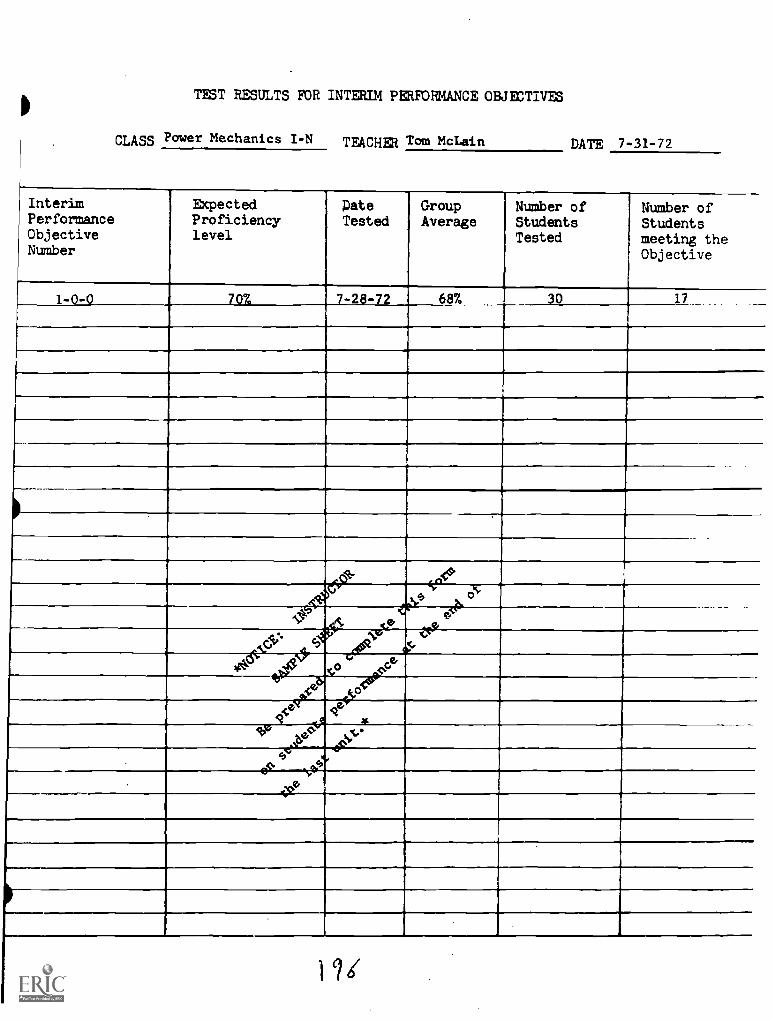
TEST RESULTS MR INTERIM PERFORMANCE OBJECTIVES
CLASS Power Mechanics I-N TEACHER Tom McLain DATE 7-31-72
InterimPerformanceObjectiveNumber
ExpectedProficiencylevel
PateTested
GroupAverage
Number ofStudentsTested
Number ofStudentsmeeting theObjective
1-0-0 70% 7-28-72 68% 30 17
dk eiPc
c
#N7
°.e
iqt 44 0V G
VP,e' tPcot
N:b°
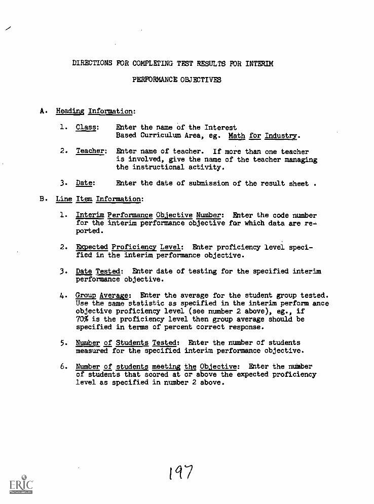
DIRECTIONS FOR COMPLETING TEST RESULTS FOR INTERIM
PERFORMANCE OBJECTIVES
A. Heading Information:
1. Class: Enter the name of the InterestBased Curriculum Area, eg. Math for Industry.
2. Teacher: Enter name of teacher. If more than one teacheris involved, give the name of the teacher managingthe instructional activity.
3. Date: Enter the date of submission of the result sheet .
B. Line Item Information:
1. Interim Performance Objective Number: Enter the code numberfor the interim performance objective for which data are re-ported.
2. Expected Proficiency Level: Enter proficiency level speci-fied in the interim performance objective.
3. Date Tested: Enter date of testing for the specified interimperformance objective.
4. Group Average: Enter the average for the student group tested.Use the same statistic as specified in the interim perform anceobjective proficiency level (see number 2 above), eg., if70% is the proficiency level then group average should bespecified in terms of percent correct response.
5. Number of Students Tested: Enter the number of studentsmeasured for the specified interim performance objective.
6. Number of students meeting the Objective: Enter the numberof students that scored at or above the expected proficiencylevel as specified in number 2 above.
197
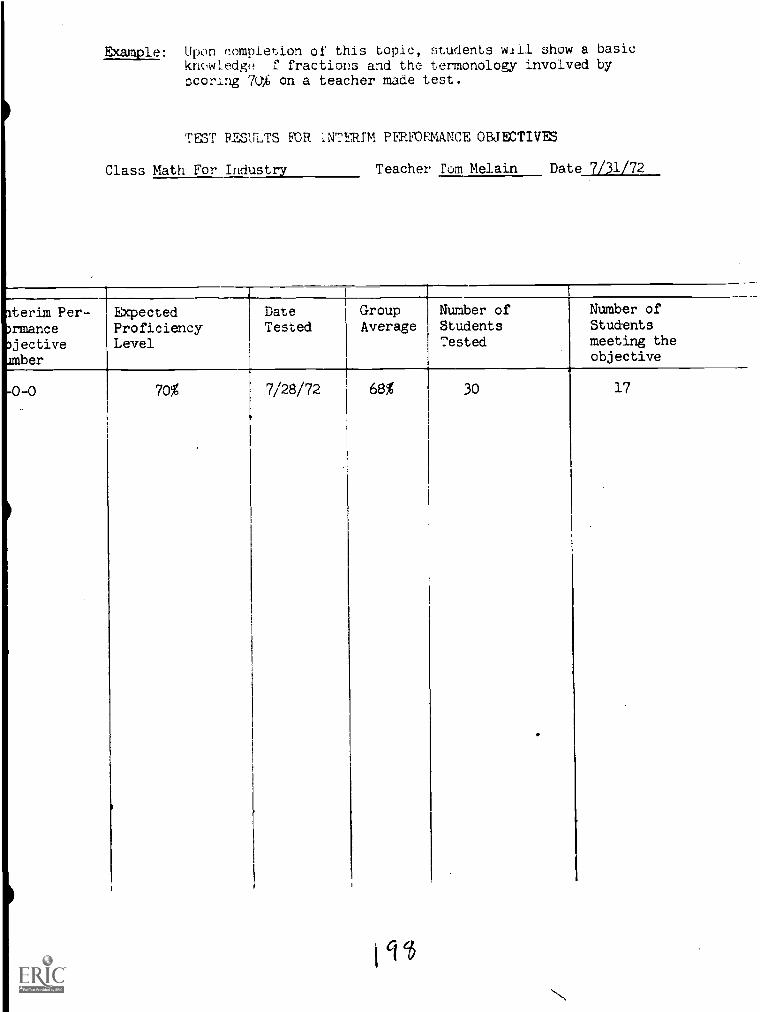
Example; Upon completion of this topic, students will show a basickm,wLedge f fractions and the termonology involved byscoring 7U% on a teacher made test.
TmT RMILTS FIOR INTERIM PatMEMANCI:', OBJECTIVES
Class Math For Industry Teacher rom Melain Date 7/31/72
Iterim Per-DrmanceDjectiveamber
-0 -0
ExpectedProficiencyLevel
DateTested
GroupAverage
Number ofStudentsTested
Number ofStudentsmeeting theobjective
70% 7/28/72 68% 30 17
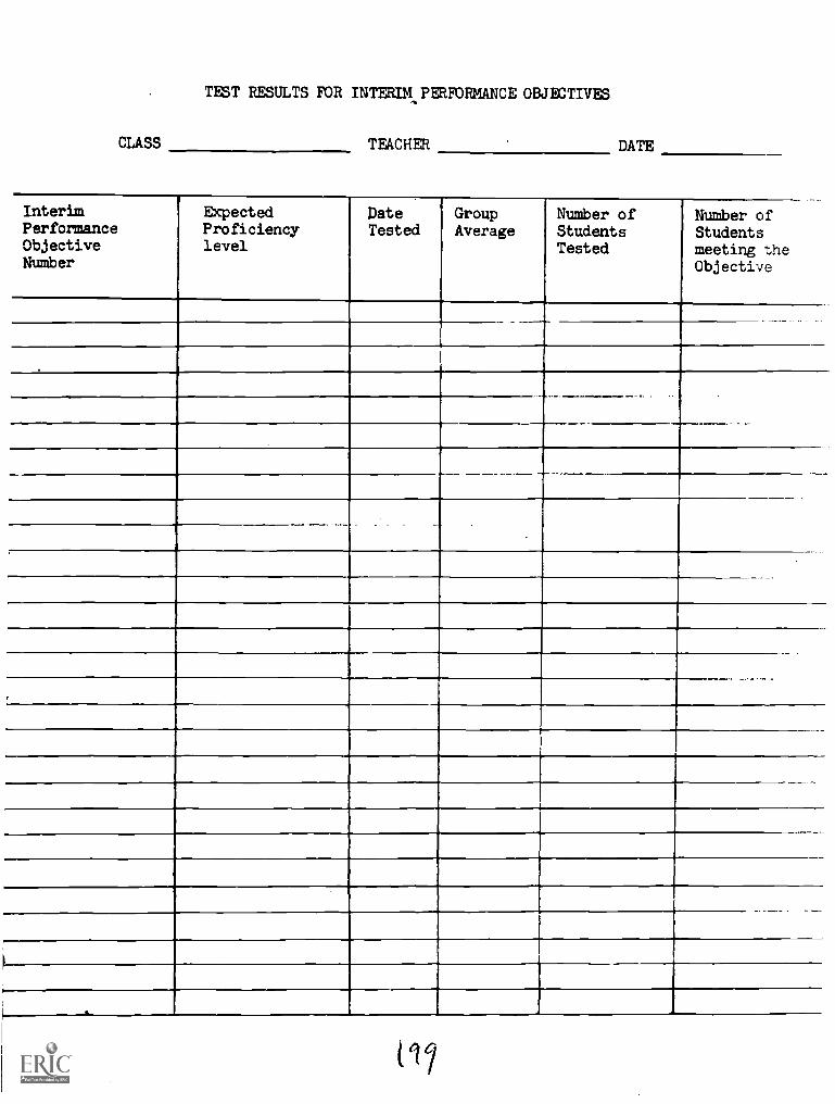
CLASS
TEST RESULTS FOR INTERIM PERFORMANCE OBJECTIVES
TEACHER DATE
InterimPerformanceObjectiveNumber
ExpectedProficiencylevel
pateTested
GroupAverage
Number ofStudentsTested
Number ofStudentsmeeting theObjective
, .
117
POWER MECHANICS GLOSSARYSHOP SAFETY
UNIT II
1. Carbon Dioxide (kgr' bon di-ox'-ide)-(CO2)- Product of complete combustionof carbon fuels. Used in gaseous forms as a fire extinguisher and insolid form as dry ice.
2. Carbon Monoxide (kgr'-bon mon- ok'- sid) -(CO )- An odorless, colori( SS,
tasteless, deadly-poisiorlous gas formed by incomplete combustion ofcarbon fuels.
3. Creeper (creep' $r)- A low platform supported on small casters on whichan automobile repairman may lie while working under a car.
4. Flamability (flam' 9-bil'-i-ty)- The condition of a substance to burneasily after being exposed to air and fire.
5. Hydraulic Jack (hi-dr61-lik)- A device for raising weight or exertinpressure by pumping oil or other liquid under a piston or ram.
6. Maintenance (main'-t9 -nance)- Proper care, repair, and keeping in goodorder.
7. Spontaneous Comubstion (spon-ta'-ni- be com-bus' ch en)- The ignitionor combustion of a substance by heat generated within itself.
8. Viscosity (vis-kos'-9 -ti)- The friction of a liquid substance ag.ainstits carrier, and its resistance to flow.
PREVENTIVE MAINTENANCEUNIT III
1. Shock Absorber (shok ab-sorb' 9r)- That portion of the front suspensionthat absorbs shock. It is usually a two-piece cylinder type mechanismoperated by fluid or air.
2. Adjust (ad-just')- To bring about a proper arrangement of parts as rtbarcisto relation, position, fit, etc.
3. Air-Cleaner (klen' Sr)- A device designed to separate dnd
foreign substances from the atmosphere before it enters the combustionspace.
4. Back-up (bak'-up)-Reverse.
5. Battery (bat'- 9r-i)- Set of one or more electric cells that produceelectric current.
/ 201
6. Balancing (bal'-gns-ing)- To adjust to insure smooth and regular motionsin an engine or machine.
7. Cable (ca'-b 8 1)- An insulated electrical conductor or group of conductors,protected by a waterproof coat.
8. Carburetor (k.ars bu-ret' 90- A device for converting liquid fuel intovapor and mixing it with air in such proportions as to form the mostefficient combustible mixture.
9. Control (con-trol')- A device that regulates speed; controls.
10. Clutch (kluch)- A device placed between engine and transmission whichpermits the engine to run free when the left foot pedal is depressed,or to drive the car when the pedal is released.
11. Crank-case (krangk kas)- The lower part of an automobile engine whichacts as a reservior for the supply of lubrecating oil.
12. Dimmer switch (dim' Sr swich)- A device used to change the headlightsto higher or lower beams.
13. Distributor (dis-tribLii-t3 r)- The device, operating in fixed time withthe engine, which distributes the iiIgh-tension current to the spark plugs.
14. External (eks-ter' n8 1)- On the outside; outer.
15. Filter (fil'-ter)- A device consisting of choke coils and condensers usedfor smoothing out a varying current, eliminating, or permitting to pass,certain alternating-current frequencies.
16. Flasher (flash'er)- A device for flashing on and off a lamp or group oflamps as in some electric signs,
17. Fluid (flu' id)- A substance that yields to any force tending to changeits form from without changing its volume.
18. Fuel pump (fu' a1)- A device operated by a piston or diaphrogm to createvacuum which insures supply of fuel to carburetor or mixing chamber.
19. Horn (horn)- A sounding device on a car used as a warning system.
20. Lights (sealed-beams)- The combined assembly consisting of lens,reflector, and lamps in a sealed vacuum or gas container.
21. Ignition (ig-nish' en)- The lighting of the charge in gas engines,effected generally by an electric spark.
22. Inspection (in-spek' shen)- The process of examining the parts andmaterials of manufactured articles to insure that the specifications ofmanufacture have been met.
202
23. Lubrication (lui-bre-ka-sh a n)- The act of applying lubricants.
24. Muffler (muf-1 9 r)- A mechanical device consisting usually of a hollowcylinder attached to the exhaust pipe of a gasoline engine through whichthe exhaust is passed in order to partially deaden the sound.
25. Paper-element (pa-130r el'-9 -me nt)- An unsized rag paper made entirelyfrom fibers, and used to filter dust particles from the air.
26. Polyurethane (pol'-i-Ar'O-than)- A type of material in making airfilters for the carburetor.
27. Positive-Control Valve (pozi- 8 (PC)- A device to direct crank-case fuems to the carburetor or intake manifold in order that they maybe burned rather than dispelled into the air as a raw fume.
28. Relay(re.'-la)- A device for opening or closing a local circuit undergiven conditions in a main circuit.
29. Service (ser'-vis)- That part of an electrical installation between thepole transformers and the meters and their associated equipment.
30. Signal (sig'-n0 1)- Devices used to give directions.
31. Sludge (sluj)- Oily deposits such as accumulates in a crankcase.
32. Speedometer (spe-d-om'- -t 8 r.)- An instrument for recording distancetraveled and the rate of speed in miles per hour.
33. Tension (ten'-sh0n)- A pulling force; the opposite of compression.
TOOLS AND THEIR FUNCTIONSUNIT IV
1. Bolt (13510- A fastening; commonly a piece of metal with head andthreaded body for the reception of a nut.
2. Clearance (kler'- ans)- The amount of space, open, or free, betweenadjustment parts.
3. Copper(kops- a r)- A metal, soft, ductile, but nbt strong; of great valuein the forming of alloys.
4. Device (di-vis')- A mechanical aid or contrivance which serves to promotethe better performance of a job.
203
5. Charging (ch*A"-jing)- The process of charging electrochemically theplates and electrolyte of a storage cell or battery.
6. Circuit (ser' -kit)- The course followed by an electric current passingfrom its source through a succession of conductors and back to itsstarting point.
7. Circuit breaker (ser'-kit 00- A switch, usually automatic,which opens to stop the flow of current.
8. Condenser (k r/ n-den'-ser)- (Mech.) A vessel in which the condensationof gases is effected. (Elec.) An accumulation of electrical energy.
9. Coil (koil)- Successive turns of insulated wire which create a magneticfield when an electric current passes through them.
10. Discharging (dis-cheirj'-ing)- Rid of an electric charge; withdrawelectricity from a source.
11. Disassembly (dis'-sem'-bli)- To separate the different parts of amachine or engine.
12. Generator (jen'- Or-a-ta r)- Term applied to machines which are used forthe transformation of mechanical energy into electrical energy.
13. Induction (in-duk'-sh D n)- The production of magnetization or electri-fication in a body by the mere proximity of magnetized or electricalbodies, or of an electric current in a conductor by the variation ofthe magnetic field in its vicinity.
14. Lamp (lamp)- A device having a filament or which, when heated toincandescence, gives off light.
15. Magnetic field (mag'-net-ik)- The space in the vicinity of a magnetthrough which magnetic forces act.
16. Over-haul (o'-var hg1)- To take apart, inspect, repair, and reassemble,as a piece of machinery.
17. Regulator Voltage (reg.'-u-la-tar vol'-tij)- A device of electromag-netically operated contact points and a resistance unit which, whenconnected in series with the held of an auto generator, reduces thegenerator's output when the battery reaches a predetermined voltage.
18. Rheostat (re'-1, -stat)- A device for regulating electrical current, inwhich the current is made to flow through wires having considerableresistance.
204
5. Drilling (dril'-ing)- A device very accurately made of cast or wroughtiron which becomes a guide for the drilling of holes.
6. Extractor (eks- trak' -t$ r)- A device used to remove bolts that arobroken off even with the surface.
7. Fastening (fas'- 8 n-ing)- Such holding devices as bolts, screws, keys,etc.
8. Heating coil (het'-ing koil)- Device used.
9. Install(in-stS1')- Placing items in position for use.
10. Iron (I: 21rn)- A device used to unit, under proper heat, pieces ofmetal.
11. Nut (nut)- A small block of metal or other material commonly squareor hexagonal in shape, having internal threads to receive a bolt.
12. Solder (sod'- Zr)- An alloy used for joining metals together underheat.
13. Splicing (solis-I ing)- The process of joining two or more leads orslugs for the purpose of obtaining a length equal to their total.
14. Stud bolt (stud b610- A bolt threaded at both ends with blank spacebetween to permit gripping with a pipe wrench.
15. Tapping (tap'-ing)- The threading of a hole by means of a tap, eitherby hand or by machine.
16. Tolerance (tol' ar- Ons)- Allowable inexactness or error in dimensionsof manufactured machine parts.
ELECTRICAL SYSTEMUNIT V
1. Accessory (ak -ses'- a ri)- A mechanical part or attachment not ,I,cessarilya part of the ma,hine with which it is to be used but does no._possible a wider range of work or better performance.
2. Adjustment (9 '-just'-ment)- The placing and setting of engi"e or machineparts in related position.
3. Alternator (AoP-ter-na-ta r)- An electric generator which produces
alternating current.
4. Calibration (kal'-e-bra'-sh On)- Ascertaining the amount of variationfrom absolute accuracy in a scientific instrument.
205
19. Spark rlu trk plug)- A device for conducting the high tensioncurron combustion space where the charge is fired by the sparkas it ::,in of the plug.
20. Switci n%- A device for opening and closing an electric circuit.
21. Timing The adjustment of valves and crankshaft of anengine in t:'.eir dative position to produce the greatest effectiveoutput in H.P. L2) The point at which ignition breaker is set inrelation 71dcenter position of the piston to secure thegreatest ,'ff.ctive expansion force upon head of piston.
22. Transi.i r)- A compact unit performing many of thefunctions ,acuum tubes in electronic circuits with the advantageof s,r.ali 't- and cool instantaneous operation.
FUEL SYSTEMUNIT VI
1. Accl. (1k-seit- 9r-a-t a 0- A mechanical device for regulatingthe lmour.t .1f gas mixture which is fed to the engine, usually operated
2. Anti-knock (an'-ti-knock)- A substance which brings about uniformexpansion of the products of combustion.
3. Carburetor barrel r bar' ao- The metal portion ofthe carourtor surrounding the suction air chamber forming a wall orbarrt-1 i r tht full length from choke to flange.
.4. Carburttor (klir'-bu-ra't a r) - A device for converting liquid fuel intovapor and mixing it with air in such proportions as to form the most
cnmhustible mixture.
5. Float (carburetor)- Usually an air tight metal container whichfloats on the surface of the fuel in the bowl of the carburetor andcontrols the flow of gasoline from the main fuel line.
6. Fuel (fu' al)- Combustion matter, such as wood, coal, gas, or oil,!I: used to feed a fire or operate an engine.
7. Fumes (:77. - Vapor, gas, or smoke, especially if harmful, strong orodorous.
8. Gallon (-11'n1- A unit of liquid measure containing 4 quarts, 8 pints,231 cubic inches.
9. Idling Jets (i'd ling jets)- The jet which controls the amount of gasneeded for operating the engine at idling speed.
206
10. Injector (in-ject')- A device used for affording a continuous supplyof gasoline to the engine.
11. Jets (jets)- (a) A spout or nozzle; (2) That which spurts out.
12. Lean-mixture (len-miks'cher)- A fuel mixture which contains too muchair in proportion to gasoline.
13. Linkage (lingk'-ijl- A device used on engines for controlling valveaction.
14. Pump (pump)- A machine for lifting or forcing liquids, either bymeans of a nu4..ket or of a pistion working in a closed cylinder.
15. Rich (rich)- Mixture consisting of a high proportion of fuel.
16. Super-charger (su'- per- char'j 0r)- A mechanical device designed togive position fuel mixture to racing motors and airplane motors.
17. Throttle (throt' el)- To shut off or regulate, as steam. A devicefor accoplIsning the same.
18. Vacuum (vak'-uam)- A pump used to remove condensation and airfrom the return main of a heating system in order to (a) createa vacuum and (b) return the condensate to the boiler or to areceiving tank.
EXHAUST SYSTEM
UNIT VII
1. Aluminum alloys ( -ne m al'-oi)- The combination of aluminumand other metals, such as copper, nickel, tungsten, etc., to producecastings and sheets where strength and lightness are required. Thesealloys are more valuable than aluminum.
2. Asbestos (as-bes'-t 0 s)- A fibrous variety of amphibole distinguishedby its ability to resist high temperatures and the action of acids,and capable of being spun and woven.
3. Carbon monoxide (lege-bon mon- oks -Id)- CO, An odorless, colorless,tasteless, deadly-poisonous gas formed by incomplete combustion ofcarbon fuels.
4. Condensation (kon'-den sa'shlIn)- The change of a substance from avapor int,- 3 liquid state to cooling.
5. Corrosion (k8 rOlzhen)- The rusting or oxidation of metals by contactand chemical union with oxygen in a damp atmosphere.
6. Damper (dam'p 8 r)- A plate, valve cover, or other contrivance forregulating draught.
207
7. Exhaust (eg-zost')- The passage through which the spent steam on anengine cylinder is carried to the outer air or to a condenser.
8. Exhause Emission Control (eg-zost' i- mish'- an ken-trol)- A deviceto reduce the level of unburned hydrocarbons and carbon monoxide fromthe engine exhaust system.
9. Gaskets (gas'-kit)- Paper, metal,rubber, or specially prepared materialsused between cylinder head and cylinder, or under similar conditions, toprevent leaking.
10. Glass pack muffler (glas pak muf'12r)- A straight through mufflerutilizing fiber glass packing around a perforated pipe to deadenexhaust sound.
11. Heat Riser (hot riz' ar)- An area, surrounding a portion of the intakemanifold, through which exhaust gases can pass to heat the fuel mixtureduring warm-up.
12. Leak (110- A hole or crack not meant to be there that lets somethingin or out.
l3. Manifold (man' fold)- A pipe or number of pipes connecting a seriesof holes or outlets to a common opening.
14. U Clamp (klamp)- A clamp shapped like the letter "U" used for clampingthe tail pipe to the muffler.
15. Valve (vale)- A device used to either open or close an opening.
ENGINE TUNE-UPUNIT VIII
1. Block (blok)- That part of the Angine containing the cylinders.
2. Cam gear (kam 60- A device used to drive the camshaft.
3. Camshaft (kamshaft)- A device with lobes (bumps) used to operate thevalves.
4. Clockwise (klok' wiz)- Rotation to the right as that of clock hands.
5. Counter-Clockwise (koun'tar klok' wiz)- Rotation Lo the left as theopposite movement of clock hands.
6. Harmonic Balancer (bgr-monLik an-sar)- A round weighted deviceattached to the front of the crankshaft to minimize the torsionalvibration.
208
. Switch (i-nish'- en swich)- An electrical control which completesor hr. to izuition coil tither by wiping contacts ortv!c.1_ fingers.
Marksti:3t. al
fire.
;)-- (Timing)- Marks on engine flywheel or dynamic balancerat the instant No. 1 cylinder is ready for
. .--,.ir of removable de.yices that are opened and closedt- T--,, pri^ary circuit.
111. : :11: -? 9 1)- A connecting point in an electrical circuit.
Ti 7 (T.D.C.)- The extreme top position of the No. 1 pistoni"
INTRODUCTION TO INTERNAL OPERATIONOF THE ENGINE
UNIT IX
^1 rt-lin'-inc)- Bringing the various parts of a unit into
7 ;;.:Ct to each other or to a predeterminedlo.ation.
;i1n.; (a -sett'-1:1-ing)- The putting together in correct relationwhich a piece of mechanism.
3. T",: area or unit in which the contacting surface of
Bands or straps of leather, canvas, or other material,rnnileh to act as a transmitter of power over smooth pulleys,
1--in v friction only.
5. T "< operation of making or finishing circular holesin wood or metal.
-T/6. bv7.3ass +H.-pas valv)- A valve that can open and allow a fluid to
pass L'clrou..: JL than its normal channel.
7. Cooliu, s.;sct.:7: sist-t 2m) Those devices which prevent theoverhc,:in -;gine by rapidly carrying off the heat generated1 cor-h;:qtion. Radiators, fans, pump and water jackets are parts ofa water-cooling system.
8. Combustion (kgm-bus'-ch9 n) - The process involved during burning.
9. Connecting Rod (ka -nek'-ting)- The connecting link between the pistonand the crankshaft.
209
10. Cylinder (sil'- an-d r) - The hole, or holes, in the cylinder blockthat contain the pistons.
11. Cylinder Block (sil'- an-d9r blok)- The main body of the engine whichis bored to receive the pistons, The cylinder block and crankcase arefrequently cast as one piece.
12. Cylinder Head (E."- .n-d 9 r hed)- The metal section that is bolted ontop of the block. It is used to cover the tops of the cylinders.
13. Design A plan or sketch made to serve as a pattern from whichto work; a design for a machine.
14. Drive Belt: (drlv belts)- Bands or straps which are strong and flexibleto act as a t7ansmitter of power over smooth pulleys, acting by frictiononly.
15. Frame (fi3m)- The unit which include all parts of the car except the body.The chasis.
16. Flywheel (fli-hwel)- A heavy wheel used in machinery where reciprocalmotion is converted into circular motion.
17. Honing (h-Oni-ing)- Removing metal with a fine grit abrasive stone toprecise tolerance.
18. Journal (jertn ? 1) - The support portion of a shaft, that part whichrevolves in the bearing.
19. Lifters (lif'ta (Hydraulic)- A valve lifter that utilizes hydraulicpressure from the engine's oiling system to keep it in constant contactwit!: :zmsaft and the valve stem.
20. Lubrication (lu'-brO -1CP-shan)- The act of applying lubricants.
21. Mechanism (melt.-9 -nlz- 9m)- Means or ways by which something is done;technique.
22. Micrometer (711-kromg-a-t r)- A precision measuring tool that will givereadings accurately with a fraction of one thousandth of an inch.
23. Offset (of'-set')- A connecting rod which is bent in two places, mayshow the piston pin to be parallel to the bearing when tested on analigner. Such a rod will be offset.
24. Pin (pin)- (Piston pin or wrist pin)- A steel pin that is passed throughthe piston.
25. Piston (pis'ta n)- A round plug, open at one end, that slides up anddown in the cylinder. It is attached to the connecting rod, when thefuel charge is fired, will transfer the force of the explosion to theconnecting rod then to the crankshaft.
210
(pis'-t 9 n rings)- A splint ring installed in a groove in
Re -co (rz-kan-dish'- an-ing)- To adjust and repair so as tobe us.ic..t.
28. Rocker-arms (row'- 8 r)- An arm used to direct the upper motion of the,,nward or opening motion of the valve stem.
29. Ro: a. "-sbe n)-Turning, or causing to turn or revolve, as
30. Scalin (sl. ing)- The accumulation of rust and minerals within the
31. Sorvici71: serivis-ing)- A term used to denote normal maintenance ofi :gr. greasing, etc.
32,
or SA7.-ing)- A hollow tube or cylinder which surrounds a rod
33. Tappinl:. (tap'-ing)- The threading of a hole by means of a tap, eitherby hand or by a machine.
34. ik.rmastacs (they.' -ma stat)- A temperature sensitive device used inthu cooling system to control the flow of collant in to the temperature.
35. Mit-2at.: (screw)- Projections left by cutting a helical grooveon a
36. Valu,.: s (val'-u sgts)- That part of the engine block machine tor' ei 7oppet valve and provides a seal against leakage of gases.
37. VnlunSnring.s (val'-u springs)- A compression-type spring exerting!,0 to 90 pounds to keep valves in closed position.
38. Ventilators (ven'-t2 15'tiOrs)- A device for providing fresh air;Pxhaustinc! foul air.
BRAKING SYSTEMUNIT X
1. Bleeding (bled-ing)- The Brakes- This refers to the removal of airsystem.
2. Brakes (brIks)- Anything to use to check motion of a wheel or vehicleby pressing or strapping.
211

3. Brake Cylinder (brlk sil'- 8n-d PO- (Wheel cylinder)- The part of thehydraulic brake system that receives pressure from the master cylinderand in turn applies the brake shoes to the drums.
4. Brake-Disc Type (bilk disk tip)- A braking system that instead ofusing the conventional brake drum with internal brake shoes, usesa steel disc with caliper type lining application. When the brakesare applied, a section of lining on each side of the spinning disc isforced against the disc, thus imparting a braking force.
5. Brake Lining. (bilk lin'-ing)- A friction material fastened to the brakeshoes, It is pressed against the rotating brake drum, thus stoppingthe car.
6. Brake Pedal (bilk ped'- 81)- The foot pedal which controls the appli-cation of brakes.
7. Brake Power (brak pow' er)- A conventional hydraulic brake system andutilizes engine vacuum to operate a vacuum power piston.
8. Brake Shoes (brik shUs)- That part of the brake system located at thewheels, upon which the brake lining is attached. When the wheel cylindersare actuated by hydraulic pressure, they force the brake shoes apartand bring the lining into contact with the drum.
9. 'Diaphragm (d11 Ofram)- A flexible cloth-rubber sheet that is stretchedacross and on an area thereby separating two different compartments.
10. Fluid Brakes (flti'-id brIks)- A special fluid used in hydraulic brakesystems.
FRONT SUSPENSIONUNIT XI
1. Absorbers (shock) (ab-strb' Or)- An oil filled device used to controlspring oscillation in the suspension system.
2. Coil Spring (koil spring)- A section of spring steel rod wound in aspiral pattern or shape. Widely used in both front and rear sus-pension systems.
3. Front Alignment (frunt a -lin'-m nt)- To bring the various partsof a unit into the correct positions in respect to each other orto a predetermined location.
4. Linkage (litgks-ig)- Movable bars or links connecting one unit toanother.
5. Power Steering (pow'- ar ster-ing)- A steering system utilizing hydraulicpressure to increase the driver's turning effort.
212
6. Rotary Valve (ro' -t& -ri valv)- A device that relives all springpr2ssurc so that it is free to rotate.
7. Sleev, IF17,v)- A hollow tube or cylinder which surrounds a rod orshaft.
8. Stablizer Bar (sta' -bQ ar bar)- A transverse mounted springsteel bar that controls and minimizes body lean or tipping on corners.
9. Steer (stir)- A term applied to the guiding of a course: steer a car,steer an airplane.
10. Suspension (s s-pen'-shan)- Arrangement of springs for supporting thebody of an automobile, railroad car, etc.
11. Tie-Rod (tI rod)- The transverse rod connecting the front wheels of anautomobile in order to permit them to act as a unit in steering.
12. Toe-in (to in)- Relates to the setting of the front wheels so that theywill be 1/8 to k inch closer together at the front than at the rear.
13. Toe-Out (t"6 out)- Having the front of the wheels further apart thanthe back.
14. Torsion (tArt-t4h an)- The act of twisting. The tendency to deform asa rod, by twisting.
15. Vane (van)- A thin plate that is affixed to a rotatable unit to eitherthrow off air or liquid, or to receive the thrust imparted by bothmoving air or liquid striking the vane. In the first case, it wouldbe acting as a pump and in the second case, as a turbine.
TRANSMISSIONUNIT XII
1. Automatic (8-t-mat'-ik)- Self-regulating or self-adjusting.
2. Bearings (bair' -ing)- The area or unit in which the contacting surfaceof a revolving part rests.
3. Cast Iron (cast iron)- Iron of ordinary use, cast molds; has high carboncontent; cannot be rolled, forged, or tempered.
4. Clutch (kluch)- A devise used to connect or disconnect the flow ofpower from one unit to another.
213
r- n arl- A device for regulating the speed of:1,i yes.
a')- Operated by the hand. That which is done by
Overir- (-.-- driv')- An arrangement of gears whereby event'or spee ana power are produced than in high.
8. Park:n tparkg-in link'-ij)- A device to engage the parkinggear of to o transmtssion connected between the transmission and theshift L
9. Pinnion Gr.,: \pin' -y &n ger)- The smaller gear of a pair, eitherlovoi or 7zpur, regardless of size.
10. Powerflit. (pow'- 9r flit)- An automatic transmission supplied oncars built by Chrysler Corp.
11. Pump (-,:77)- A machine for lifting or forcing liquids, either bymeans of a bucket or of a piston working in a closed cylinder.
12. Synchrorn,.sh Transmission (sing'-kr2 -mesh trans-mish'- en)- Amechanical device designed to make gear shifting easy or silent.
13. R.P.M.- Revolutions Per Minute.
14. Thrust washers (thrust wash'- drs)- A bronze or a hardened steelwasher placed between two moving parts. The washer preventslongitudinll movement and provides a bearing surface for the thrust
parts.
15. Torque (tArk)- Turning or twisting force, such as the force impartedon the drive line by the engine.
16. 7vr-er (tArk k2n-very- 2r)- A unit quite similar to thefluid r:-1;plinv, that transfers engine torque to the transmissionimp -`,'ft,
17. TransTission (trans-mish.- en)- A device that uses gearing or torqueconversion to effect a change in the ratio between engine RPM anddrivirw RPM.
DRIVE LINEUNIT XIII
1. Flange Bearing (flang blr'-ing)- The turned edge of a metal shape orplate, which resists bending strain.
214
2. Parking (n!;rk'-ing)- Leaving an automobile for a time in a certainplacte.
3. Snag (snap ring)- A split ring that is snapped in a shaft or ina grocAt in a hole. It is used to hold barrings, gears, etc., in place.
4. Spider Cea: Or ge-r)- The two, three, or four gears (as the casemay be) fittc.: trae running on the spider, by means of which differen-tial :ictinn 1, '-.Lainer.! in the gear axle.
DIFFERENTIAL
UNIT XIV
1. Alignment -lin'-ment)- To bring the various parts of a unit intocorrect positions in respect to each other to a predetermined location.
2. Carrier (kar'-i- 90- Same as lathe dog. The most common form is clampedon in the faceplate causing rotation of the piece. The cylindricalpiece ....ill he turned and has a projecting tail which is engaged in a slot.
3. Joint (inint)- To join. fasten, or secure two or more pieces together.
4. Propellor (pra 9r) (shaft)- The shaft connecting the transmissionoutput shaft to the differential pinnion shaft.
5. Sure-grip (shUr' grip)- A device for grasping or holding.
6. Trunnion (trun'-y- en)- One of two opposite cylindrical supporting lugsor projections from the side of an object, which allows it to be turnedon an ,-*-
7. Universal Joint (u' -n9 - ver' -s 91 joint)- A type of coupling whichpermits the free rotation of two shafts whose axes are not in astraight line.
8. Velocity (ye -los'-9 -ti)- It is the distance divided by time, and isexpressed in feet per second or per minute.
AIR-CONDITIONINGUNIT XV
1. Compressor (Ica m-pres'- a r)- A device that draws in low pressurerefigerant from the evaporator and compress it.
2. Freon (fre"-on)- Dichlorodifluromethane. Used as a refrigerant.
A gas used as the cooling medium in air conditioning and refrigerationsystems.
215
3. Refrigerant (ri-frij'-a r- ant)- The liquid in refrigeration systemsto remora 'seat from the evaporator coils and carry it to the condenser.
'4. Refrigeration (ri-frij'- arls -shan)- Act or process of cooling orkeeping cold.
5. Temperature (tee-per- a-char)- Degree of heat or cold.
6. Wet Sleeve (wet slev)- A cylinder sleeve application in which thewater in the cooling system contacts a major portion of the sleeveitself.
216
BIBLIOGRAPHY
Americn Safe: v Code for Woodworking Mac:.inery. AmericanStand Assoclation.
Crouse, " Mechanics. New York: McGraw-Hill BookCompany, Inc., ,
Douglas, J. H. Woo.t:inc. o' Machines. McNight Publishing Company, 1960.
Hducaion f . . 1,-r.:,u,:n the School Shop. Accident PreventionDeparcl- z Association of Casualty and Security Company,New York.
Feirer, John L. Industrial Arts Woodworkings. (Revised), Illinois:Charles Bennett Company, Inc, 1960.
. Woodworking for Industry. Illinois: Charles BennettCompar,-. Inc.. 1970.
Advanced Wookwork and Furniture Makings. CharlesInc., i963.
Frvklund, Verne C. and La Berge, Armand J. General Shop Woodworking.XcNight Puhlishing Company, 1958.
Goneman. r:=. ':?cdworking,_ New York: McGraw-Hill BookCorp;::', Inc., 1959.
Hammond, .117't '-1 '.7oodworking Technology. Bloomington,Illinois: McNight Publishing Company, 1961.
Safety in Industrial Arts for Louisiana Schools. Bulletin No. 1203.State D "partment of Public Education of Louisiana, 1971.
Shea and Wenner. Woodworking for Everybody. (Third Edition), Illinois:Van Nos, 1969.
Silvia, G. H. Safer Practices in Woodworking and Plastics, 1954.
Smith, Robert E. ,igachine Woodworking. Bloomington, Illinois: McNightPublishing Company, 19S8.
Tryon, George H. (ed.). International Fire Prevention Handbook. (TwelfthEdition), Joa.Vn, .!ass.: 1962.
Wagner, Willis H. Woodworking. (Revised Edition), Goodheart-Willcox,1968.
World Book Encyclopedia Dictionary.
?< /218
PiRLIOGRAPHY
Stockel, Aiartin \V. Auto Mechanics Fundamentals. South Holland, Illionis:Good-Heart Will .Thnipany, 1969.
Worthington, Robert ..iarquies, Morton and Crouses, William H. GeneralPower Mechan. .:Lnv York: McGraw- Hill Book
Tobuldt, ,7-. Chevrolet. South Holland, Illinois: The Good-HeartWilico;, .1::
Crouse. Automotive Mechanics. Third Edition. New York:Mc Craw- lull Book Company, Inc. 1956.
Gleen. Harold Automotive Engine Rebuilding and Maintenance. Philadelphia:Chilton Company, 1956.
Murphy, Paul A. Chilton's Auto Repair Manual. New York: Chilton Booki.););-,.
Basic Automotive Series. The Ignition System, Cranking and Charging Circuits.Delmar Publishers: Litton Educational Publishing, Inc.; 1970.
Basic Automotive Series. The Fuel System. Delmar Publishers: LittonEducational Publishing. Inc. 1970.
Basic Automotive Series. The Brake stem. Delmar Publishers: LittonEducational Publishing, Inc. 1970.
Basic Automotive Series. The Differential System. Delmar Publishers:Litton EL1ucauu,411 Inc. 1970.
Basic Automotive Series. The Steering System. Delmar Publishers:Litton Educational Punishing, Inc. 1970.
Basic Automotive Series. The Standard Transmission. Delmar Publishers:Litton Educational Publishing, Inc. 1970.
Basic Automotive Series. The Lubrication System. Delmar Publishers:Litton Educational Publishing, Inc. 1970.
Vocational Curriculm Development and Research Center. State VocationalTechnical and Trade School of Louisiana; Auto Mechanics.Curriculum Development Research Center.
219
REFERENCE LIST
Douglas, J. H. Woodworking With Machines. McNight, 1/60. PP. 46,48,58,59,65,70,89,97,102,110,111,114,121,162.
Feirer, John L. Industrial Arts Woodworkings. (Revised), Illinois:Charles Bennett Company, Inc., 1960. P. 29.
. Advanced Woodwork and Furniture Makings. CharlesBennett, Company, 1963. PP. 152, 159,169,211,235,243,259.
Woodworking for Industry. Illinois: Charles BennettCompany, Inc., 1970. PP. 28-31,204,212,219,236,
Fryklund, Verne C. and La Berge, Armand J. General Shop Woodworking.Illinois: McNight, 1958. PP. 13,14,76,92,93,101,116,179,180,181,190,201 204,210.
Goneman, Chris. General Woodworking. New York: McGraw-Hill BookCompany, Inc., 1959. PP. 11,12,13.
Harmond, James J. and others. Woodworking Technology. Bloomington,Illinois: McNight Publishing Company, 1961. P. 367.
Shea and Wegner. Woodworking for Everybody. (Third Edition), Illinois:Van Nos, 1969. P. 123.
Smith, Robert E. Machine Woodworking. Bloomington, Illinois: McNight,1958. P. 9.
Wagner, Willis H. Woodworking. (Revised Edition), Coodheart-Willcox,1968. PP. 9,14,32,58,66,69,71,75,80.
220
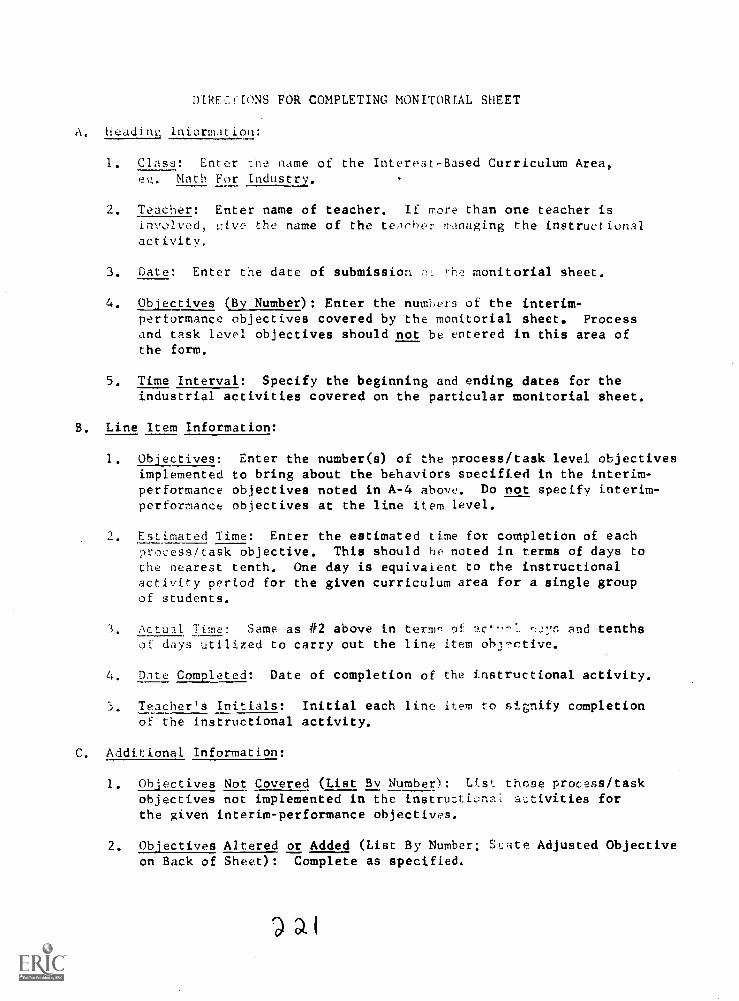
DIRFCCEONS FOR COMPLETING MONITORIAL SHEET
A. headia information:
1. Class: Enter :he name of the Interest-Based Curriculum Area,e,!,. Math For Industry.
2. Teacher: Enter name of teacher. If more than one teacher isinvolved, p:ive the name of the teArher ,,,Inaging the instructionalactivity.
3. Date: Enter the date of submission the monitorial sheet.
4. Objectives (By Number): Enter the numbers of the interim-performance objectives covered by the monitorial sheet. Processand task level objectives should not be entered in this area ofthe form.
5. Time Interval: Specify the beginning and ending dates for theindustrial activities covered on the particular monitorial sheet.
B. Line Item Information:
1. Objectives: Enter the number(s) of the process/task level objectivesimplemented to bring about the behaviors specified in the interim -performance objectives noted in A-4 above. Do not specify interim-performance objectives at the line item level.
2. Estimated Time: Enter the estimated time for completion of eachprocess/task objective. This should he noted in terms of days tothe nearest tenth. One day is equivalent to the instructionalactivity period for the given curriculum area for a single groupof students.
3, Actual Time: Same as #2 above in term,.. of ,27:r, and tenths
of days utilized to carry out the line item objctive.
4. Date Completed: Date of completion of the instructional activity.
5. Teacher's Initials: Initial each line item to signify completionof the instructional activity.
C. Additional Information:
1. Objectives Not Covered (List By Number): Ust those process/taskobjectives not implemented in the instrurtinol activities forthe given interim-performance objectives,
2. Objectives Altered or Added (List By Number; Sate Adjusted Objectiveon Back of Sheet): Complete as specified.
)ai
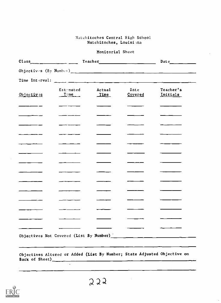
Natchitoches Central High SchoolNatchitoches, Louisiana
Monitorial Sheet
Class Teacher Date
Objectiv.,s (By Numbvi)
Time Interval:
Ob'ectiv2sEst-mated Actual Date Teacher's
Time Time Covered Initials
Objectives Not Covered (List By Number)
Objectives Altered or Added (List By Number; State Adjusted Objective onBack of Sheet)