Embed Size (px)
Citation preview

For Official Use NEA/CSNI/R(97)19
Organisation de Coopération et de Développement Economiques OLIS : 06-Mar-1998Organisation for Economic Co-operation and Development Dist. : 09-Mar-1998__________________________________________________________________________________________
English text onlyNUCLEAR ENERGY AGENCYCOMMITTEE ON THE SAFETY OF NUCLEAR INSTALLATIONS
DOCUMENTATION OF THE USE OF SEVERE ACCIDENT COMPUTER CODESIN SELECTED LEVEL-2 PSAs FOR NUCLEAR POWER PLANTS
62813
Document complet disponible sur OLIS dans son format d'origine
Complete document available on OLIS in its original format
For O
fficial Use
NE
A/C
SN
I/R(97)19
English text only

NEA/CSNI/R(97)19
2
ORGANISATION FOR ECONOMIC CO-OPERATIONAND DEVELOPMENT
Pursuant to Article I of the Convention signed in Paris on 14th December 1960, and which came into force on30th September 1961, the Organisation for Economic Co-operation and Development (OECD) shall promote policiesdesigned:
− to achieve the highest sustainable economic growth and employment and a rising standard of living in Membercountries, while maintaining financial stability, and thus to contribute to the development of the world economy;
− to contribute to sound economic expansion in Member as well as non-member countries in the process ofeconomic development; and
− to contribute to the expansion of world trade on a multilateral. non-discriminatory basis in accordance withinternational obligations.
The original Member countries of the OECD are Austria, Belgium, Canada, Denmark, France, Germany, Greece,Iceland, Ireland, Italy, Luxembourg, the Netherlands, Norway, Portugal, Spain, Sweden, Switzerland, Turkey, the UnitedKingdom and the United States. The following countries became Members subsequently through accession at the datesindicated hereafter: Japan (28th April 1964), Finland (28th January 1969), Australia (7th June 1971), New Zealand(29th May 1973), Mexico (18th May 1994), the Czech Republic (21st December 1995), Hungary (7th May 1996), Poland(22nd November 1996) and the Republic of Korea (12th December 1996). The Commission of the European Communitiestakes part in the work of the OECD (Article 13 of the OECD Convention).
NUCLEAR ENERGY AGENCY
The OECD Nuclear Energy Agency (NEA) was established on 1st February 1958 under the name of the OEECEuropean Nuclear Energy Agency. It received its present designation on 20th April 1972, when Japan became its firstnon-European full Member. NEA membership today consists of all OECD Member countries except New Zealant andPoland. The Commission of the European Communities takes part in the work of the Agency.
The primary objective of the NEA is to promote co-operation among the governments of its participating countries infurthering the development of nuclear power as a safe, environmentally acceptable and economic energy source.
This is achieved by:
− encouraging harmonisation of national regulatory policies and practices, with particular reference to the safetyof nuclear installations, protection of man against ionising radiation and preservation of the environment,radioactive waste management, and nuclear third party liability and insurance;
− assessing the contribution of nuclear power to the overall energy supply by keeping under review the technicaland economic aspects of nuclear power growth and forecasting demand and supply for the different phases ofthe nuclear fuel cycle;
− developing exchanges of scientific and technical information particularly through participation in commonservices;
− setting up international research and development programmes and joint undertakings.
In these and related tasks, the NEA works in close collaboration with the International Atomic Energy Agency inVienna, with which it has concluded a Co-operation Agreement, as well as with other international organisations in thenuclear field.
© OECD 1998Permission to reproduce a portion of this work for non-commercial purposes or classroom use should be obtained throughCentre français d’exploitation du droit de copie (CCF), 20, rue des Grands-Augustins, 75006 Paris, France, for everycountry except the United States. In the United States permission should be obtained through the Copyright ClearanceCenter, Inc. (CCC). All other applications for permission to reproduce or translate all or part of this book should be made toOECD Publications, 2, rue André-Pascal, 75775 PARIS CEDEX 16, France.

NEA/CSNI/R(97)19
3
COMMITTEE ON THE SAFETY OF NUCLEAR INSTALLATIONS
The Committee on the Safety of Nuclear Installations (CSNI) of the OECD Nuclear EnergyAgency (NEA) is an international committee made up of senior scientists and engineers. It was set up in1973 to develop, and co-ordinate the activities of the Nuclear Energy Agency concerning the technicalaspects of the design, construction and operation of nuclear installations insofar as they affect the safety ofsuch installations. The Committee's purpose is to foster international co-operation in nuclear safety amongthe OECD Member countries.
The CSNI constitutes a forum for the exchange of technical information and for collaborationbetween organisations which can contribute, from their respective backgrounds in research, development,engineering or regulation, to these activities and to the definition of the programme of work. It alsoreviews the state of knowledge on selected topics on nuclear safety technology and safety assessment,including operating experience. It initiates and conducts programmes identified by these reviews andassessments in order to overcome discrepancies, develop improvements and reach international consensuson technical issues of common interest. It promotes the co-ordination of work in different Membercountries including the establishment of co-operative research projects and assists in the feedback of theresults to participating organisations. Full use is also made of traditional methods of co-operation, such asinformation exchanges, establishment of working groups, and organisation of conferences and specialistmeetings.
The greater part of the CSNI's current programme is concerned with the technology of waterreactors. The principal areas covered are operating experience and the human factor, reactor coolantsystem behaviour, various aspects of reactor component integrity, the phenomenology of radioactivereleases in reactor accidents and their confinement, containment performance, risk assessment, and severeaccidents. The Committee also studies the safety of the nuclear fuel cycle, conducts periodic surveys ofthe reactor safety research programmes and operates an international mechanism for exchanging reportson safety related nuclear power plant accidents.
In implementing its programme, the CSNI establishes co-operative mechanisms with NEA'sCommittee on Nuclear Regulatory Activities (CNRA), responsible for the activities of the Agencyconcerning the regulation, licensing and inspection of nuclear installations with regard to safety. It alsocooperates with NEA's Committee on Radiation Protection and Public Health and NEA's RadioactiveWaste Management Committee on matters of common interest.
* * * * * * * * * * * *
The opinions expressed and the arguments employed in this document are the responsibility ofthe authors and do not necessarily represent those of the OECD.
Requests for additional copies of this report should be addressed to:
Nuclear Safety DivisionOECD Nuclear Energy AgencyLe Seine St-Germain12 blvd. des Iles92130 Issy-les-MoulineauxFrance

NEA/CSNI/R(97)19
4
ABSTRACT
The use of severe accident computer codes in published PSAs for PWR and BWR plants is documented.The report examines whether correlations exist between quantitative results obtained at the various levelsof the analysis and the use of particular computer codes.

NEA/CSNI/R(97)19
5
FOREWORD
The NEA Committee on the Safety of Nuclear Installations (CSNI) believes that an essential factor inachieving their mandate is the continuing exchange and analysis of technical information. To facilitatethis exchange CSNI has established various working group. To deal with technology and methods foridentifying contributors to risk and assessing their importance, the Committee established PrincipalWorking Group No. 5 - Risk Assessment in 1982. In 1987, “the Committee supported a suggestions thatPWG5’s activity should for the moment be primarily focused on PSA Level 1 methods, uses andassessments ...... (i.e., to consideration of PSA Level 2 issues where appropriate”.
Over the last 10 years the scope of PSA programmes increased progressively to where today, in manycountries, a Level 2 PSA is considered the normal standard. Accordingly, with the advent of increasinguse of PSAs, a proposal was made at the 1993 PWG5 Annual meeting for future work in the area of Level2 PSA. The main objective of the proposed task was to perform a state-of-the-art review of the methodsavailable for performing level 2 PSAs and severe accident/source term uncertainty analyses for use in theregulatory process and the evaluation/implementation of severe accident management strategies. Thisproposal was accepted by PWG5 and forwarded to the CSNI. The new task was endorsed by CSNI duringits annual meeting in 1993.
The overall scope of the task included review current Level 2-PSA methodologies and practices and toinvestigate how Level 2-PSA can support severe accident management programmes, i.e. the development,implementation, training and optimisation of accident management strategies and measures. The finalproduct is contained in CSNI Report OCDE/GD/(97)198 published in late 1997. For the most part, thepresented material reflects the state-of-the-art in 1996.
The information contained within this report reflects (along with three other reports) supplementalmaterial which was prepared in conjunction with the main report. This specific report looks at the use ofsevere accident computer codes in selected Level 2 PSAs.
Much appreciation and thanks go to the task group members listed below, who provided valuable time andconsiderable knowledge into this report. Special acknowledgement is given to Dr. Wolfgang Werner, whoas an expert consultant provided much of the in-depth technical analysis provided throughout the report aswell as many man-hours in editing and compiling the final report.
Task Group Member contributing to the report were:
Cojazzi, G. Italy Kersting, E. Germany Muramatsu.K. JapanCozzoli, E. Switzerland Kim, T.W. Korea Murphy, J.A. United StatesCunningham, M. United States Lantaron, J. Spain Otero, M. SpainEvrard, J.M. France Lee, C.J. Korea Seebregts, A. NetherlandsGrant, A. Canada Liwang, B. Sweden Shepherd, C. United KingdomHerttrich, P.M. Germany Meyer, P. Switzerland Versteeg, M.F. NetherlandsHirose, H. Japan Werner, W. Germany

NEA/CSNI/R(97)19
6
TABLE OF CONTENTS
ABSTRACT ...................................................................................................................................................4
FOREWORD.................................................................................................................................................5
1. INTRODUCTION.....................................................................................................................................7
2. SEVERE ACCIDENT COMPUTER CODES USED IN THE EXAMINED PSAs............................8
2.1 Analysis of containment loads from in-vessel phenomena at PWR plants. ..........................................82.1.1 Arrest of core melt progression, temperature induced hot leg/surge line/SGT rupture..................82.1.2 In-vessel hydrogen generation. .....................................................................................................102.1.3 In-vessel steam explosion. ............................................................................................................112.1.4 Bottom head failure.......................................................................................................................11
2.2 Analysis of containment loads from ex-vessel phenomena at PWR plants. .......................................122.2.1 Loads at vessel breach. .................................................................................................................122.2.2 Ex-vessel steam explosion. ...........................................................................................................132.2.3 Ex-vessel generation of non-condensable gases. ..........................................................................132.2.4 Loads from combustion of hydrogen and carbon monoxide. .......................................................142.2.5 Molten corium/containment structure interaction. .......................................................................142.2.6 Containment structural response...................................................................................................14
2.3 Analysis of source term issues for PWR plants...................................................................................152.3.1 In-vessel fission product release, transport and retention.............................................................152.3.2 Scrubbing of fission products in water filled steam generator or in water pool...........................152.3.3 Fission product release, transport and retention inside containment............................................152.3.4 Releases to the environment. ........................................................................................................16
2.4 Analysis of containment loads from in-vessel phenomena at BWR plants.........................................172.4.1 Arrest of core melt progression. ...................................................................................................172.4.2 In-vessel hydrogen generation. .....................................................................................................172.4.3 In-vessel steam explosion. ............................................................................................................182.4.4 Bottom head failure.......................................................................................................................18
2.5 Analysis of containment loads from ex-vessel phenomena at BWR plants. .......................................192.5.1 Loads at vessel-breach. .................................................................................................................192.5.2 Ex-vessel steam explosion. ...........................................................................................................202.5.3 Ex-vessel generation of non-condensable gases. ..........................................................................202.5.4 Combustion of hydrogen and carbon monoxide. ..........................................................................202.5.5 Molten corium/containment interaction.......................................................................................212.5.6 Containment structural response...................................................................................................21
2.6 Analysis of source term issues for BWR plants. .................................................................................222.6.1 In-vessel fission product release, transport and retention.............................................................222.6.2 Scrubbing of fission products in water pool. ................................................................................222.6.3 Fission product release, transport and retention inside containment............................................222.6.4 Releases to the environment. ........................................................................................................22
FIGURES .....................................................................................................................................................24

NEA/CSNI/R(97)19
7
1. INTRODUCTION
In this report the use of severe accident computer codes in the examined PSAs is discussed. This includesdiscussions whether correlations exist between the quantitative results at the various levels of the analysisand the use of certain severe accident computer codes.
In this report the use of severe accident computer codes in published level-2 PSAs is examined. Thediscussions cover severe accident phenomena that were found important to level-2 results for PWR andBWR plants, as listed below:
− Analysis of containment loads from in-vessel phenomena, like arrest of core meltprogression, temperature induced hot leg/surge line/SGT rupture (only PWRs), in-vesselhydrogen generation, in-vessel steam explosion and bottom head failure.
− Analysis of containment loads from ex-vessel phenomena, like loads at vessel breach, ex-vessel steam explosion, ex-vessel generation of non-condensable gases, loads fromcombustion of hydrogen and carbon monoxide, molten corium/containment structureinteraction, containment structural response.
− Analysis of source term issues, like in-vessel fission product release, transport and retention,scrubbing of fission products in water filled steam generator (only PWRs) or in water pool,fission product release, transport and retention inside containment, releases to theenvironment.
Particular emphasis is on whether correlations exist between the quantitative results at the various levelsof the analysis and the use of certain severe accident computer codes. The magnitude of uncertainties andtheir influence on the results is also examined.

NEA/CSNI/R(97)19
8
2. SEVERE ACCIDENT COMPUTER CODES USED IN THE EXAMINED PSAS
In tables 1 - 6 the severe accident computer codes used in the examined PSAs are compiled.
The tables are organised by PSA relevant issues and phenomena; listed are the computer codes applied tothe various items in the examined PSAs.
In the following, qualitative and quantitative aspects of the use of the codes are discussed. For each item ashort discussion of the phenomenological context is provided.
2.1 Analysis of containment loads from in-vessel phenomena at PWR plants
2.1.1 Arrest of core melt progression, temperature induced hot leg/surge line/SGT rupture.
Core melt progression can be arrested if injection to the RPV can be re-established. Besides recovery ofinjection by operator action, relevant passive recovery scenarios involve:
− failed steam generator feeding, high pressure in the reactor system resulting from operatorfailure to depressurise, inability to inject to the RPV, beginning core heat-up. Superheatedsteam flow is from the core through hot leg, surge line, pressuriser, out of the power operatedrelief valve (scenario 1).
− depressurisation by temperature induced passive failure of hot leg, surge line or steamgenerator heating tubes. Once the system is sufficiently depressurised, injection may berecovered. Whether or not RPV integrity can be maintained depends on the timing of thedepressurisation.
Three different assessment bases exist in the examined PSAs:
1. In the NUREG-1150 analyses, the quantification of probabilities of passive depressurisationwas based on an expert opinion elicitation process. The experts based their quantification onresults of calculations with the computer codes MELPROG, TRAC/MELPROG,CORMLT/PSAAC, RELAP5/SCDAP and MAAP, as well as on evaluation of pertinentexperiments.
For scenario (1) a conditional probability of temperature induced hot leg failure of about0.99 is obtained from the aggregation of the expert’s quantifications. If in scenario (1) a sealLOCA is induced (scenario 2) the probability of hot leg failure is much lower, i.e. about0.15. The figures are taken for all PWRs included in the NUREG-1150 analyses. Theunderlying probability distribution functions generated by the expert team for the caseswithout and with seal LOCA are shown in Figures 2.1.1-1 and 2.1.1-2.

NEA/CSNI/R(97)19
9
2. In all other examined studies but Beznau HSK/ERI, the assessment is based on calculationswith the MAAP code. For a scenario similar to the one described above, the followingquantifications are made:
− Robinson IPE: ∼0.9 (point value)
− Maine Yankee IPE: ∼0.75 (point value)
− Beznau PLG: ∼0.99 (same data as in NUREG-1150)
− Ringhals 2: ∼0.8
− Borssele: ∼0.73
3. In the Beznau HSK/ERI study the assessment is based on MELCOR results, plant specificcalculations with RELAP5/SCDAP and assessment of the TMI accident.
The conditional probability for hot leg failure in scenario 1 was estimated to be 0.75, and 0.0in scenario 2
The estimates of the conditional probabilities of temperature induced depressurisation have significantimpact on the fraction of core damage sequences remaining at high pressure at time of RPV bottom headfailure. An exact correlation can not be established because of the differing shares of relevant sequencesand scenarios.
In the examined PSAs, the following percentages of high pressure core melt sequences are reported:
Plant/PSA Percentage of highpressure core melt
sequencesSurry 3%Zion 2%Robinson 22%Maine Yankee 16%Beznau HSK/ERI 10%Ringhals 2 12%Borssele PSA-3 6%Borssele PSA-97 ?

NEA/CSNI/R(97)19
10
2.1.2 In-vessel hydrogen generation.
The amount of hydrogen generated in the in-vessel phase of core degradation and meltdown isproportional to the fraction of zirconium oxidised. The oxidation process is the result of complexinteractions of thermo-hydraulic and chemical phenomena.
Basis for the assessment in the examined PSAs are:
− in the NUREG -1150 studies:
Calculations with the program systems MELPROG, SCDAP, CORMLT, MAAP, MARCH,as well as evaluations of experiments and of the TMI-accident. A number of typical caseshave been defined, characterised by various pressure ranges and time scales, with or withoutflooding of the core.
Experts who had experience with several of the computer codes rated MAAP and MARCHlower than the others, because MAAP was considered to underestimate zirconium oxidation,and MARCH to overestimate it.
The available information was assessed by a formalised expert opinion elicitation process.Subjective probability distribution functions for the amount of oxidised zirconium have beenaggregated to one distribution function, which then was used in the quantification process.
For the investigated cases, the median values of the aggregated distribution functions arebetween 30% and 50% zirconium oxidation.
− In the IPE-studies:
Results of calculations with the program MAAP that were adapted to the specialcircumstances at the plant and evaluation of separate effect tests and of the TMI-accident.
In the Robinson study, point values are being used, which are in good agreement with themedian values in NUREG-1150. In the Maine Yankee study the point values are in the in theupper range of the distribution functions of NUREG 1150. They are generally higher that inthe other PWR studies.
In the HSK/ERI analysis of the Beznau plant the assessment is based on MELCORcalculations. The range for the fraction of oxidised zirconium is 40 - 50%. As point value,44% is used.
In the Ringhals 2 and Borssele analyses the assessment is based on MAAP calculations. Therange for the fraction of oxidised zirconium is 30% - 52 %.
The uncertainties in the modelling of in-vessel zirconium oxidation are large. However, a significantinfluence on early containment failure can only be identified in the Maine Yankee analysis. For this plant,with the fuel loaded at the time of the analysis, the ratio “amount of zirconium in the core/ containmentvolume” is much larger than for the other plants, thus making the containment vulnerable to hydrogengeneration. At the other plants examined in this study, the threat from hydrogen burn is insignificant.

NEA/CSNI/R(97)19
11
2.1.3 In-vessel steam explosion.
In all studies, the assessment of the impact of in-vessel steam explosions is based on expert judgement.Input to the expert judgement are investigations performed by the USNRC Steam Explosion ReviewGroup (NUREG 1116) /r1/, Corradini /r2/, Theofanus /r3/, Turland et al. /r4/. In all examined studies, thepotential of in-vessel steam explosions to fail the containment is considered small relative to othercontainment failure modes. The quantified conditional probabilities for containment failure due to in-vessel steam explosions, given core melt, are in the range 10-3 to 10-2 for low pressure sequences, and inthe range 10-4 to 10-3 for high pressure sequences.
2.1.4 Bottom head failure.
Important questions are: mode of bottom head failure (HPME, pour or dump); temperature, mass andfraction of metal in the ejected material.
− In the NUREG-1150 analyses the assessment is based on expert judgement. Input to theexpert judgement are calculations with the codes MELPROG and MAAP and evaluations ofthe TMI accident. The investigations covered three cases:
1. high pressure in the reactor system, no accumulator discharge, no upper head injection,
2. intermediate pressure in the reactor system, no accumulator discharge, only partial upperhead injection,
3. low pressure in the reactor system, partial accumulator discharge, upper head injectionfunctioning.
The aggregated answers of the experts are shown in the table below.
Mode of bottom head failure
Failure mode (fraction)Case RCS
pressure(psia)
HPME Pour Dump
1 2500 79% 8% 13%2 2000 60% 27% 13%3 200-1200 60% 27% 13%
Other studies: Comparable information on this issue is not provided in the examined studies.

NEA/CSNI/R(97)19
12
2.2 Analysis of containment loads from ex-vessel phenomena at PWR plants
2.2.1 Loads at vessel breach.
According to the quantifications made in the examined PSAs, the loads at vessel breach primarily resultfrom „direct containment heating“ (DCH), which is a superposition of several physical phenomena, mostnotably:
− blowdown of steam and hydrogen,
− combustion of hydrogen,
− interaction of core debris with water on the containment floor and in the cavity,
− transfer of heat from dispersed debris to the containment atmosphere.
The parameters most important to DCH loads are:
− pressure in the reactor system at time of vessel breach (see the discussion in section 2.1.1),
− amount of unoxidised metal in the core (see the discussion in section 2.1.2),
− amount of ejected core debris,
− size of hole in the RPV,
− depth of water pool in the cavity,
− availability of containment spray.
The following code systems are used for the quantification of containment loads resulting from DCH:
− In NUREG-1150: CONTAIN, MAAP, HMC.
− In the IPE studies and in the studies for Beznau PLG, Ringhals-2, Borssele: MAAP.
− In the Beznau HSK/ERI study: SCDAP/RELAP5, CONTAIN, MAAP.

NEA/CSNI/R(97)19
13
In the table below conditional probabilities related to DCH are compiled.
Conditional probabilities of DCH
PSA
Conditional probabilityof high pressure inreactor system, givencore damage
Conditional probabilityof containment failuredue to DCH, givenHPME
Conditional probabilityof containment failuredue to DCH, given coredamage
NUREG-1150 0.02-0.03 ∼ 0.2 0.004-0.006IPE, Ringhals-2,Borssele
0.1-0.22 ∼ 0.1 0.01-0.025
Beznau HSK/ERI < 0.1 0.13 0.013
The conditional probabilities are in good agreement for all large dry containments. For most plants DCH isthe main contribution to early containment failure.
All presented results on DCH loads are accompanied by large uncertainties. but the impact of theuncertainties on the failure probabilities of the large dry containments is small.
2.2.2 Ex-vessel steam explosion.
In all studies, the assessment of the impact of ex-vessel steam explosions is based on expert judgement.Input to the expert judgement are investigations performed by the USNRC Steam Explosion ReviewGroup (NUREG 1116) /r1/, Corradini /r2/, Theofanus /r3/, Turland et al. /r4/. In all examined studies, thepotential of ex-vessel steam explosions to fail the containment is considered small relative to othercontainment failure modes. The quantified conditional probabilities for containment failure due to ex-vessel steam explosions, given core melt, are in the range 10-4 to 10-3.
2.2.3 Ex-vessel generation of non-condensable gases.
Non-condensable gases generated in the ex-vessel phase are:
− hydrogen resulting from unoxidised core debris reacting with water,
− hydrogen and carbon monoxide resulting from core debris/concrete interaction.
A parameter critical to the estimation of the amount of hydrogen generated from unoxidised core debris isthe amount of zirconium in the core.
In the examined studies the following codes were used for the prediction of the amount of combustiblegases generated:
− in NUREG-1150: CORCON,
− in the Beznau PLG study: MAAP, COMPACT,
− in the Beznau HSK/ERI study: MELCOR, COBURN,
− in all other studies: MAAP.

NEA/CSNI/R(97)19
14
In the MAAP calculations it is assumed that core debris/concrete interaction is suppressed if the cavity isfilled with water. This assumption is not made in other computer codes. Therefore, for situations with thecavity being filled with water, the ex-vessel generation of non-condensable gases is significantly lower forMAAP calculations than for other codes. Otherwise, predictions of the total amount of non-condensablegases generated - scaled to the amount of zirconium in the core - agree well among the various codes.However, significant uncertainties exist on the time history of generation of combustible gases.
2.2.4 Loads from combustion of hydrogen and carbon monoxide.
Distinction is made between loads early in the accident that contribute to early containment failure, andloads late in the accident that contribute to late containment failure or - if applicable - to venting failure.Codes used for the quantification of containment loads are MAAP, HCTOR, MELCOR and ERPRA-BURN.
Loads relevant to early containment failure depend on the amount of zirconium generated in the in-vesselphase (section 0). For all examined plants but Maine Yankee, the containment loads resulting fromcombustion of hydrogen in the early phase stay clearly below containment capacities, see typicalexamples, Figures 0-1 and 0-2. Therefore, the conditional probability, given core damage, of earlycontainment failure due to combustion of gases is insignificant relative to other containment failuremodes.
The majority of combustible gases is produced in the late accident phase. Thus, higher loads than in theearly phase are seen in this phase, see a typical example, Figure 0-3, which indicates a high likelihood ofcontainment failure due to combustion of gases at plants without venting capabilities.
2.2.5 Molten corium/containment structure interaction.
Molten corium/containment structure interaction can lead to penetration by the core debris of thecontainment basemat. MAAP, CORCON and MELCOR are used for the analysis of this phenomenon.Basemat penetration is a significant contribution to containment failure at most plants, but its contributionto releases is generally low.
2.2.6 Containment structural response.
Several well established code systems are available for quantification of containment load capacity, forexample, NASTRAN; ABAQUS, DYNA3D, NEPTUNE.
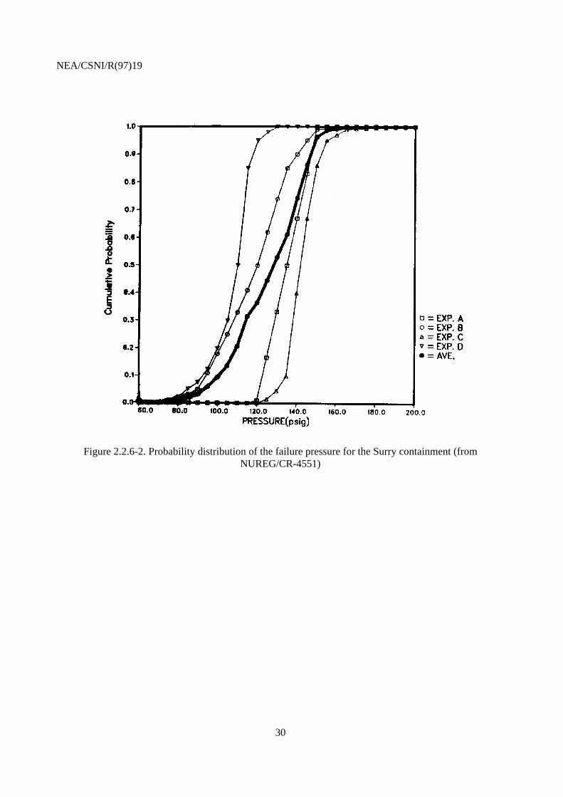
In all studies, containment failure is described by cumulative probability functions. Probability of failurebegins to rise from practically zero at about 5 bar. For the Surry and Ringhals-2 containments, probabilityof failure approaches 1 in the range 13-14 bar. For Zion NUREG-1150 and the IPE studies, probability offailure approaches 1 in the range 18-23 bar. In the examined IPE studies, higher pressures than in the otherstudies are required to fail the containment.
For illustration, see Figures 2.2.6-1 and 2.2.6-3.
For the steel containment of the Beznau plant, probability of failure approaches 1 in the range 9-10 bar,see Figure 2.2.6-4.

NEA/CSNI/R(97)19
15
2.3 Analysis of source term issues for PWR plants
2.3.1 In-vessel fission product release, transport and retention.
A large number of different code systems is used for predicting fission product release and transport insidethe reactor system and to the containment.
For NUREG-1150 these are: STCP, MAAP, ASTEC, CONTAIN, ICEDF, CORCON-MOD2, VANESSA,NAUA, as well as evaluations of experiments. For Beznau HSK/ERI, MELCOR is used, and MAAP forall other plants.
The agreement among predictions of releases and retention inside the reactor system is reasonably goodfor noble gases and volatile fission products. For the refractory aerosols, there is more disagreement ofpredictions.
2.3.2 Scrubbing of fission products in water filled steam generator or in water pool.
For mitigating releases from an unisolated defective steam generator, severe accident managementprocedures have been put in place at several plants. Essentially, the procedures are aimed at filling up adefective steam generator with a water column in which fission products are retained. For thequantification of the scrubbing effect The MAAP code system is used in the analyses for Ringhals-2 andBorssele, and the MELCOR code system in the Beznau HSK/ERI analysis.
The releases are predicted to be reduced by factors in the range 10 - 100. However, more clarification ofthis important issue is needed
In the Robinson and Maine Yankee IPEs, reductions of Cs releases by a factor 20-100 are reported forsituations in which core debris on the containment floor is covered by an overlying water pool. However,this is to be attributed to two effects:
1. suppression of the core debris/concrete interaction (an assumptions that is made in MAAP,but not in the other codes),
2. fission product scrubbing by the water pool.
The information provided does not permit to differentiate between the two effects.
2.3.3 Fission product release, transport and retention inside containment.
These issues are controlled by several phenomena which are not well understood, most notablythermophoresis, Brownian diffusion, aerosol agglomeration, aerosol plate out on surfaces, settling underinfluence of gravity. Most of these processes are governed by the aerosol particle size distribution which isnot well known. Another important factor influencing deposition and plate out is the time history of theconvection processes.
A large number of different code systems is in use for predicting fission product release and transportinside the containment.

NEA/CSNI/R(97)19
16
For NUREG-1150 these are: STCP, MAAP, ASTEC, CONTAIN, ICEDF, CORCON-MOD2, VANESSA,NAUA, as well as evaluations of experiments. For Beznau HSK/ERI, MELCOR is used, and MAAP forall other plants.
Differences among predictions are large and difficult to compare and interpret.
2.3.4 Releases to the environment.
For the calculation of source terms the XSOR suite of codes is used in the NUREG-1150 analyses,MELCOR and ERPRA are used in the Beznau HSK/ERI analysis, and MAAP in all other examinedstudies.
Suitable measures for comparing releases at different plants are the
− conditional probability of exceeding 10% Cs release, given one of the containment failuremodes „early containment failure“ (ECF), „containment bypass“ (Bypass) or „isolationfailure“ (ISF).
− conditional probability of exceeding 1% Cs release, given core damage.
In the table inserted below, these conditional probabilities are compiled for the plants examined in thissection.
Conditional probabilities for Cs releases
PSA
Conditionalprobability ofexceeding 1% Csrelease, given coredamage
Conditional probability ofexceeding 10% Cs release,given ECF or bypass or ISF
Surry, NUREG-1150 0.15 0.39Zion, NUREG 1150 update 0.08 0.66Maine Yankee IPE 0.06 0.19Robinson IPE 0.1 0.23Beznau HSK/ERI 0.03 0.05Ringhals-2 0.01 0.03
The calculated conditional probabilities reflect the combined effect of all issues discussed above,including the associated uncertainties. In view of the described differences, the agreement among plantswith comparable retention capabilities is satisfactory.
Among the US PSAs, the IPE studies calculate lower large releases than the NUREG-1150 studies, but thesource of the discrepancy is difficult to identify.
The Beznau and Ringhals-2 plants have implemented severe accident management procedures for fillingup a defective steam generator with water. The retention capability of the water column is reflected by the

NEA/CSNI/R(97)19
17
significant reduction, relative to the other plants, of the conditional probability of exceeding 10% Csrelease, given ECF or bypass or ISF.
Also, at the two plants high capacity filtered containment venting is available and severe accidentmanagement equipment and procedures are in place that permit to flood the containment using externalwater sources. This feature is reflected by the reduction, relative to the other plants, of the conditionalprobability of exceeding 1% Cs release, given core damage.
2.4 Analysis of containment loads from in-vessel phenomena at BWR plants
2.4.1 Arrest of core melt progression.
Core melt progression can be arrested if injection to the RPV can be re-established. The relevant scenariosinvolve
− recovery of AC power if the accident was initiated by loss of AC power,
− operator actions to depressurise the reactor and align low pressure injection systems insituations with failed high pressure injection and failed automatic depressurisation.
2.4.2 In-vessel hydrogen generation.
The amount of hydrogen generated in the in-vessel phase of core degradation and meltdown isproportional to the fraction of zirconium oxidised. The zirconium oxidation is the result of complexthermo-hydraulic and chemical interactions. Basis for the assessment in the examined PSA s are:
− In the NUREG -1150 studies:
Calculations with the program systems MELPROG, SCDAP, CORMLT, MAAP, MARCH,BWRSAR and APRIL, as well as evaluations of experiments and of the TMI-accident. Anumber of typical cases have been defined, characterised by various pressure ranges and timescales, with or without flooding of the core.
Experts who had experience with several of the computer codes rated MAAP and MARCHlower than the others: MAAP was considered to underestimate zirconium oxidation, andMARCH to overestimate it.
The available information was assessed by a formalised expert opinion elicitation process.Subjective probability distribution functions for the amount of oxidised zirconium have beenaggregated to one distribution function, which then was used in the quantification process.
For the investigated cases, the median values of the aggregated distribution functions arebetween 10% and 25% zirconium oxidation.

NEA/CSNI/R(97)19
18
− In the IPE-studies:
Results of calculations with the program MAAP that were adapted to the specialcircumstances at the plant and evaluation of separate effect tests and of the TMI-accident.
In the Browns Ferry and Perry studies, nominal values are being used, which are in goodagreement with the median values of the distribution functions of NUREG-1150.
In the HSK/ERI analysis of the Mühleberg plant the assessment is based on MELCORcalculations. The range for the fraction of oxidised zirconium is 21% - 25%.
2.4.3 In-vessel steam explosion.
In all studies, the assessment of the impact of in-vessel steam explosions is based on expert judgement.Input to the expert judgement are investigations performed by the USNRC Steam Explosion ReviewGroup (NUREG 1116) /r1/, Corradini /r2/, Theofanus /r3/, Turland et al. /r4/. In all examined studies, thepotential of in-vessel steam explosions to fail the containment is considered small relative to othercontainment failure modes. The quantified conditional probabilities for containment failure due to in-vessel steam explosions, given core melt, are below 10-3.
2.4.4 Bottom head failure.
Important questions are: mode of bottom head failure (HPME, pour or dump); temperature, mass andfraction of metal in the ejected material.
− In the NUREG-1150 analyses the assessment is based on expert judgement. Input to theexpert judgement are calculations with the codes BWRSAR and MAAP and evaluations ofthe TMI accident. Of the investigated cases, three are presented here:
1. high pressure in the reactor system, no injection,
2. low pressure in the reactor system, no injection
3. low pressure in the reactor system, LPI injection restored, no recriticality after LPIrestoration.
The aggregated answers of the experts are shown in the table below.
Mode of bottom head failure
Failure mode (fraction)Case RCS
pressureHPME Pour Dump
1 high 80% 20%2 low 75% 25%3 low 74% 26%
Other studies: Comparable information on this issue is not provided in the examined studies.

NEA/CSNI/R(97)19
19
2.5 Analysis of containment loads from ex-vessel phenomena at BWR plants
2.5.1 Loads at vessel-breach.
The pressure rise at vessel breach primarily results a superposition of several physical phenomena, mostnotably:
− blowdown of steam and hydrogen,
− combustion of hydrogen,
− interaction of core debris with water in the pedestal area,
− transfer of heat from dispersed debris to the containment atmosphere,
− impulse loads.
The parameters most important to DCH loads are:
− pressure in the reactor system at time of vessel breach,
− amount of unoxidised metal in the core,
− amount of ejected core debris,
− size of hole in the RPV,
− depth of water pool in the pedestal area,
− availability of containment spray.
The following code systems are used for the quantification of the pressure rise at vessel breach:
− In NUREG-1150: CONTAIN, MAAP, HMC.
− In the IPE studies and in the studies for Barsebäck, Forsmark 3: MAAP.
− In the Mühleberg PLG study: BWRSAR/CONTAIN.
− In the Mühleberg HSK/ERI study: MELCOR.
Loads due to vessel breach are among the dominant containment failure modes in all examined PSAs.
NEA/CSNI/R(97)19
20
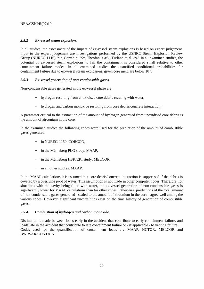
2.5.2 Ex-vessel steam explosion.
In all studies, the assessment of the impact of ex-vessel steam explosions is based on expert judgement.Input to the expert judgement are investigations performed by the USNRC Steam Explosion ReviewGroup (NUREG 1116) /r1/, Corradini /r2/, Theofanus /r3/, Turland et al. /r4/. In all examined studies, thepotential of ex-vessel steam explosions to fail the containment is considered small relative to othercontainment failure modes. In all examined studies the quantified conditional probabilities forcontainment failure due to ex-vessel steam explosions, given core melt, are below 10-3.
2.5.3 Ex-vessel generation of non-condensable gases.
Non-condensable gases generated in the ex-vessel phase are:
− hydrogen resulting from unoxidised core debris reacting with water,
− hydrogen and carbon monoxide resulting from core debris/concrete interaction.
A parameter critical to the estimation of the amount of hydrogen generated from unoxidised core debris isthe amount of zirconium in the core.
In the examined studies the following codes were used for the prediction of the amount of combustiblegases generated:
− in NUREG-1150: CORCON,
− in the Mühleberg PLG study: MAAP,
− in the Mühleberg HSK/ERI study: MELCOR,
− in all other studies: MAAP.
In the MAAP calculations it is assumed that core debris/concrete interaction is suppressed if the debris iscovered by a overlying pool of water. This assumption is not made in other computer codes. Therefore, forsituations with the cavity being filled with water, the ex-vessel generation of non-condensable gases issignificantly lower for MAAP calculations than for other codes. Otherwise, predictions of the total amountof non-condensable gases generated - scaled to the amount of zirconium in the core - agree well among thevarious codes. However, significant uncertainties exist on the time history of generation of combustiblegases.
2.5.4 Combustion of hydrogen and carbon monoxide.
Distinction is made between loads early in the accident that contribute to early containment failure, andloads late in the accident that contribute to late containment failure or - if applicable - to venting failure.Codes used for the quantification of containment loads are MAAP, HCTOR, MELCOR andBWRSAR/CONTAIN.

NEA/CSNI/R(97)19
21
Loads relevant to early containment failure depend on the amount of zirconium generated in the in-vesselphase (section 2.4.2). For examined plants with Mark III containments, which are not inerted, hydrogencombustion is a dominant contribution to containment failure. At all plants with inerted containment, theconditional probability, given core damage, of early containment failure due to combustion of gases ispractically zero.
2.5.5 Molten corium/containment interaction.
Molten corium exiting the reactor pressure vessel can erode the pedestal structure. In many Mark Icontainments the in-pedestal sump volume is too small to accomodate the molten core. Therefore, moltencorium may spill over to the drywell floor and lead to drywell shell meltthrough and subsequent erosion ofthe concrete drywell structure.
− In the NUREG-1150 studies, expert elicitation was performed for both pedestal erosion anddrywell attack. The results provided by the experts differed widely. Research results thathave since become available have removed some of the discrepancies, as they indicate thatconcrete erosion and drywell shell attack can be reduced by the presence of water. This issuewas controversial at the time of the expert elicitation.
Input to the predictions by the experts were calculations with CORCON.
− In the Mühleberg PLG study, the CONTAIN is used, and in the Mühleberg HSK/ERI theTEXAS code is used.
− In all other studies, predictions are based on MAAP calculations.
For US plants with Mark I containments there still may be significant contributions to early containmentfailure from molten corium/containment interaction. For all other plants, only insignificant contributionsare reported.
2.5.6 Containment structural response.
Several well established code systems are available for quantification of containment load capacity, forexample, NASTRAN; ABAQUS, DYNA3D, NEPTUNE.
In all studies, containment failure is described by cumulative probability functions. For plants with MarkIII containments, probability of failure begins to rise from practically zero at about 4-5 bar, and probabilityof failure approaches 1 in the range 7-8 bar. For plants with Mark I containments, probability of failurebegins to rise from practically zero at about 7-8 bar, and probability of failure approaches 1 in the range18-20 bar.
For illustration, see Figures 2.5.6-1 and 2.5.6-2.

NEA/CSNI/R(97)19
22
2.6 Analysis of source term issues for BWR plants
2.6.1 In-vessel fission product release, transport and retention.
A large number of different code systems is used for predicting fission product release and transport insidethe reactor system and to the containment.
For NUREG-1150 these are: STCP, MAAP, ASTEC, CONTAIN, ICEDF, CORCON-MOD2, VANESSA,NAUA, as well as evaluations of experiments. For Mühleberg PLG, BWRSAR(RMA), CORSOR-M, andfor Mühleberg HSK/ERI, MELCOR is used, For all other plants, MAAP is used.
The agreement among predictions of releases and retention inside the reactor system is reasonable fornoble gases, CsI and CsOH. For Te and the refractory aerosols, there is considerable disagreement ofpredictions.
2.6.2 Scrubbing of fission products in water pool.
In most accident sequences, gas mixtures containing aerosol particle pass through the pressure suppressionpool where very effective scrubbing of fission products takes place. For the quantification of the scrubbingeffect STCP with the SPARC module is used in NUREG-1150, MELCOR is used for MühlebergHSK/ERI, and MAAP for the others. Reported fission product reduction factors typically are in excess of1000.
2.6.3 Fission product release, transport and retention inside containment.
These issues are controlled by several phenomena which are not well understood, most notablythermophoresis, Brownian diffusion, aerosol agglomeration, aerosol plate out on surfaces, settling underinfluence of gravity. Most of these processes are governed by the aerosol particle size distribution which isnot well known. Another important factor influencing deposition and plate out is the time history of theconvection processes.
A large number of different code systems is in use for predicting fission product release and transportinside the containment.
For NUREG-1150 these are: STCP, MAAP, ASTEC, CONTAIN, ICEDF, CORCON-MOD2, VANESSA,NAUA, as well as evaluations of experiments. For Mühleberg PLG, CONTAIN is used, for MühlebergHSK/ERI, MELCOR and ERPRA are used, and MAAP for all other plants.
Differences among predictions are large and difficult to compare and interpret.
2.6.4 Releases to the environment.
For the calculation of source terms the XSOR suite of codes is used in the NUREG-1150 analyses,MELCOR and ERPRA are used in the Mühleberg HSK/ERI analysis, and MAAP in all other examinedstudies.

NEA/CSNI/R(97)19
23
Suitable measures for comparing releases at different plants are the:
− conditional probability of exceeding 10% Cs release, given one of the containment failuremodes „early containment failure“ (ECF), „containment bypass“ (Bypass) or „isolationfailure“ (ISF),
− conditional probability of exceeding 1% Cs release, given core damage.
In the table inserted below, these conditional probabilities are compiled for the plants examined in thissection.
Conditional probabilities for Cs releases
PSA
Conditionalprobability ofexceeding 1% Csrelease, given coredamage
Conditionalprobability ofexceeding 10% Csrelease, given ECF orbypass or ISF
Peach Bottom, NUREG-1150 0.46 0.54Grand Gulf, NUREG 1150 0.36 0.58Browns Ferry IPE 0.25 0.22Perry IPE 0.33 0.26Mühleberg HSK/ERI 0.1 0.13Barsebäck-2 0.13 0.36
The calculated conditional probabilities reflect the combined effect of all issues discussed above,including the associated uncertainties. In view of significant differences in the quantifications in thevarious analysis steps, the agreement among plants with comparable retention capabilities is satisfactory.
Among the PSAs for US plants, the IPE studies calculate lower large releases than the NUREG-1150studies, but the source for this discrepancy can only be speculated on. One reason may be the differenttreatment of core debris covered by water by the MAAP code in which core concrete interaction ispractically suppressed in such situations, see section 2.5.3.
At Mühleberg and Barsebäck, high capacity filtered containment venting is available and severe accidentmanagement equipment and procedures are in place that permit to flood the containment using externalwater sources. This feature is reflected by the reduction, relative to the other plants, of the conditionalprobability of exceeding 1% Cs release, given core damage.
Mühleberg has the lowest conditional probability of exceeding 10% Cs release. In relation to US plants,this can be explained by the much larger in-pedestal sump volume which can easily accomodate the wholemolten core. This practically eliminates the drywell attack problems seen in US plants with Mark Icontainment.
In relation to Barsebäck which does not have the drywell attack problem, the low exceedance frequencycan be explained by additional retention in the strong reactor building which acts as a secondarycontainment and from which the release path for sequences bypassing the filter is through an outer waterfilled torus.

NEA/CSNI/R(97)19
24
FIGURES

NEA/CSNI/R(97)19
25
Figure 2.1.1-1. Induced hot leg failure in PWRs, scenario 1 (from NUREG/CR-4551)

NEA/CSNI/R(97)19
26
Figure 2.1.1-2. Induced hot leg failure in PWRs, scenario 2 (from NUREG/CR-4551)

NEA/CSNI/R(97)19
27
Figure 2.2.4-1. Distribution of loads due to hydrogen combustion at vessel breach for a high pressurescenario at Beznau (from ERI/HSK 94-301, Vol. 2)
Figure 2.2.4-2. Distribution of loads due to hydrogen combustion at vessel breach for a low pressurescenario at Beznau (from ERI/HSK 94-301, Vol. 2)

NEA/CSNI/R(97)19
28
Figure 2.2.4-3. Distribution of loads due to hydrogen and carbon monoxide in the late stages of anaccident at Beznau (from ERI/HSK 94-301, Vol. 2)

NEA/CSNI/R(97)19
29
Figure 2.2.6-1. Probability distribution of the failure pressure for the Zion containment (fromNUREG/CR-4551)
NEA/CSNI/R(97)19
30
Figure 2.2.6-2. Probability distribution of the failure pressure for the Surry containment (fromNUREG/CR-4551)

NEA/CSNI/R(97)19
31
Figure 2.2.6-3. Probability distribution of the failure pressure for the Robinson (HRB2) containment (fromRobinson IPE)

NEA/CSNI/R(97)19
32
Figure 2.2.6-4. Probability distribution of the failure pressure for the Beznau containment (from ERI/HSK94-301)

NEA/CSNI/R(97)19
33
Figure 2.5.6-1. Probability distribution of the failure pressure for the Perry containment (from Perry IPE)

NEA/CSNI/R(97)19
34
Figure 2.5.6-2. Probability distribution of the failure pressure for the Browns Ferry containment (fromBrowns Ferry IPE)

NE
A/C
SN
I/R(9
7)19
35
Tab
le 1
. Com
pute
r co
des
used
in th
e ex
amin
ed P
SA
s fo
r an
alys
is o
f con
tain
men
t loa
ds fr
om in
-ves
sel p
heno
men
a in
PW
Rs
Ph
en
om
en
aP
SA
Arr
est o
f cor
e m
elt
pro
gres
sion
Tem
pera
ture
indu
ced
hot
leg/
surg
e lin
e/S
GT
rup
ture
In v
esse
l hyd
roge
nge
nera
tion
In-v
esse
l ste
am e
xplo
sion
Bot
tom
hea
d fa
ilure
NU
RE
G-1
150
Sur
ryD
ep
en
ds
on
Leve
l-1 s
yste
ms
anal
ysis
para
met
ers
Like
lihoo
d of
pas
sive
depr
essu
risat
ion
mec
hani
sms
(col
umn
2)R
ate
of a
ccid
ent
prog
ress
ion
(ME
LCO
Rca
lcul
atio
ns)
Hot
leg/
surg
e lin
e ru
ptur
eM
ELP
RO
G,
TR
AC
/ME
LPR
OG
,C
OR
MLT
/PS
AA
C,
RE
LAP
5/S
CD
AP
,M
AA
Pus
ed b
y ex
pert
pan
elm
embe
rs
ME
LPR
OG
SC
DA
PC
OR
MLT
MA
RC
HM
AA
Pus
ed b
y ex
pert
pan
elm
embe
rs
Exp
ert j
udge
men
t, ba
sed
onU
SN
RC
Ste
am E
xplo
sion
Rev
iew
Gro
up (
NU
RE
G1
11
6)
/r1
/, C
orr
ad
ini /
r2/,
The
ofan
us /r
3/, T
urla
nd e
ta
l. /r
4/
ME
LPR
OG
, MA
AP
anal
ysis
of T
MI a
ccid
ent,
used
by
expe
rt p
anel
mem
bers
NU
RE
G-1
150
Zio
nD
ep
en
ds
on
Leve
l-1 s
yste
ms
anal
ysis
para
met
ers
Like
lihoo
d of
pas
sive
depr
essu
risat
ion
mec
hani
sms
(col
umn
2)R
ate
of a
ccid
ent
prog
ress
ion
(ME
LCO
Rca
lcul
atio
ns
Hot
leg/
surg
e lin
e ru
ptur
eM
ELP
RO
G,
TR
AC
/ME
LPR
OG
,C
OR
MLT
/PS
AA
C,
RE
LAP
5/S
CD
AP
,M
AA
Pus
ed b
y ex
pert
pan
elm
embe
rs
ME
LPR
OG
SC
DA
PC
OR
MLT
MA
RC
HM
AA
Pus
ed b
y ex
pert
pan
elm
embe
rs
Exp
ert j
udge
men
t bas
ed o
nU
SN
RC
Ste
am E
xplo
sion
Rev
iew
Gro
up (
NU
RE
G1
11
6)
/r1
/, C
orr
ad
ini /
r2/,
The
ofan
us /r
3/, T
urla
nd e
ta
l. /r
4/
ME
LPR
OG
, MA
AP
anal
ysis
of T
MI a
ccid
ent,
used
by
expe
rt p
anel
mem
bers
Ro
bin
son
IPE
De
pe
nd
s o
nLe
vel-1
sys
tem
s an
alys
ispa
ram
eter
sLi
kelih
ood
of p
assi
vede
pres
suris
atio
nm
echa
nism
s (c
olum
n 2)
MA
AP
MA
AP
Exp
ert j
udge
men
tM
AA
P
Mai
ne Y
anke
e IP
ED
epen
ds o
nLe
vel-1
sys
tem
s an
alys
ispa
ram
eter
sLi
kelih
ood
of p
assi
vede
pres
suris
atio
nm
echa
nism
s (c
olum
n 2)
MA
AP
MA
AP
Exp
ert j
udge
men
tM
AA
P
Bez
znau
PLG
MA
AP
MA
AP
MA
AP
Exp
ert j
udge
men
tM
AA
P

NE
A/C
SN
I/R(9
7)19
36
Tab
le 1
. Com
pute
r co
des
used
in th
e ex
amin
ed P
SA
s fo
r an
alys
is o
f con
tain
men
t loa
ds fr
om in
-ves
sel p
heno
men
a in
PW
Rs
Ph
en
om
en
aP
SA
Arr
est o
f cor
e m
elt
pro
gres
sion
Tem
pera
ture
indu
ced
hot
leg/
surg
e lin
e/S
GT
rup
ture
In v
esse
l hyd
roge
nge
nera
tion
In-v
esse
l ste
am e
xplo
sion
Bot
tom
hea
d fa
ilure
Bez
nau
HS
K/E
RI
ME
LCO
RS
CD
AP
/RE
LAP
5,N
UR
EG
-115
0 re
sults
, TM
Iev
alua
tion
ME
LCO
RE
xper
t jud
gem
ent,
base
d on
wor
k by
The
ofan
us /r
31/
Co
rra
din
i/x2
/, a
nd
HS
Ksp
onso
red
anal
yses
.
ME
LCO
R
Rin
ghal
s 2
MA
AP
MA
AP
MA
AP
Exp
ert j
udge
men
t, ba
sed
onw
ork
by T
heof
anus
/r3/
Co
rra
din
i (r2
)
MA
AP
Bor
ssel
eM
AA
PM
AA
PM
AA
PE
xper
t jud
gem
ent
MA
AP

NE
A/C
SN
I/R(9
7)19
37
Tab
le 2
. Com
pute
r co
des
used
in th
e ex
amin
ed P
SA
s fo
r an
alys
is o
f con
tain
men
t loa
ds r
esul
ting
from
ex-
vess
el p
heno
men
a, P
WR
s.
Ph
en
om
en
aP
SA
Load
s at
ves
sel b
reac
hE
x-ve
ssel
ste
ame
xplo
sio
nE
x-ve
ssel
gen
erat
ion
of
no
n-c
on
de
nsa
ble
gase
s
Com
bust
ion
ofhy
drog
en a
nd c
arbo
nm
onox
ide
Mol
ten
coriu
m/c
onta
inm
ent s
truc
ture
inte
ract
ion
Con
tain
men
tst
ruct
ura
l re
spo
nse
to
pres
suris
atio
nN
UR
EG
-115
0S
urry
CO
NT
AIN
, MA
AP
,H
MC
Exp
ert j
udge
men
t,ba
sed
on N
UR
EG
11
16
/r1
/, C
orr
ad
ini
/r2/
, The
ofan
us /r
3/,
Tur
land
et a
l. /r
4/
CO
RC
ON
Exp
ert j
udge
men
t,H
EC
TR
CO
RC
ON
NU
RE
G-1
150
Zio
nC
ON
TA
IN, M
AA
PE
xper
t jud
gem
ent
base
d N
UR
EG
111
6/r
1/,
Co
rra
din
i /r2
/,T
heof
anus
/r3/
,T
urla
nd e
t al.
/r4/
Exp
ert j
udge
men
t,H
EC
TR
Str
uctu
ral a
naly
sis
code
s
Ro
bin
son
IPE
MA
AP
Exp
ert j
udge
men
tM
AA
PM
AA
PM
AA
PS
truc
tura
l ana
lysi
sco
des
Mai
ne Y
anke
e IP
EM
AA
PE
xper
t jud
gem
ent
MA
AP
MA
AP
MA
AP
Str
uctu
ral a
naly
sis
code
sB
ezna
u P
LGM
AA
PE
xper
t jud
gem
ent
MA
AP
CO
MP
AC
T, M
AA
PS
truc
tura
l ana
lysi
sco
des
Bez
nau
HS
K/E
RI
SC
DA
P/R
ELA
P5,
CO
NT
AIN
, MA
AP
Exp
ert j
udge
men
t,ba
sed
on w
ork
byT
heof
anus
/r3/
Co
rra
din
i /r2
/, a
nd
HS
K s
po
nso
red
anal
yses
.
ME
LCO
RM
ELC
OR
, ER
PR
A-
BU
RN
ME
LCO
RS
truc
tura
l ana
lysi
sco
des
Rin
ghal
s 2
MA
AP
Exp
ert j
udge
men
base
d on
NU
RE
G1
11
6 /
r1/,
Co
rra
din
i/r
2/, T
heof
anus
/r3/
,T
urla
nd e
t al.
/r4/
MA
AP
MA
AP
MA
AP
Str
uctu
ral a
naly
sis
code
s
Bor
ssel
eM
AA
PE
xper
t jud
gem
ent
MA
AP
MA
AP
MA
AP
Str
uctu
ral a
naly
sis
code
s

NE
A/C
SN
I/R(9
7)19
38
Tab
le 3
. Com
pute
r co
des
used
in th
e ex
amin
ed P
SA
s fo
r an
alys
is o
f sou
rce
term
issu
es, P
WR
s.
Ph
en
om
en
aP
SA
In-v
esse
l fis
sion
pro
duct
rel
ease
,tr
an
spo
rt a
nd
re
ten
tion
Scr
ubbi
ng in
wat
er fi
lled
stea
mge
nera
tor
or in
wat
er p
ool
Fis
sio
n p
rod
uct
re
lea
se,
tra
nsp
ort
an
d r
ete
ntio
n in
sid
e c
on
tain
me
nt
Env
ironm
enta
l rel
ease
NU
RE
G-1
150
Sur
ryS
TC
P, M
AA
P, A
ST
EC
,C
ON
TA
IN, I
CE
DF
, CO
RC
ON
-M
OD
2, V
AN
ES
SA
, NA
UA
,ex
perim
ents
,
ST
CP
, MA
AP
, AS
TE
C,
CO
NT
AIN
, IC
ED
F, C
OR
CO
N-
MO
D2,
VA
NE
SS
A, N
AU
A,
expe
rimen
ts,
SU
RS
OR
NU
RE
G-1
150
Zio
nS
TC
P, M
AA
P, A
ST
EC
,C
ON
TA
IN, I
CE
DF
, CO
RC
ON
-M
OD
2, V
AN
ES
SA
, NA
UA
,ex
perim
ents
,
ST
CP
, MA
AP
, AS
TE
C,
CO
NT
AIN
, IC
ED
F, C
OR
CO
N-
MO
D2,
VA
NE
SS
A, N
AU
A,
expe
rimen
ts,
ZIS
OR
Ro
bin
son
IPE
MA
AP
MA
AP
MA
AP
MA
AP
Mai
ne Y
anke
e IP
EM
AA
PM
AA
PM
AA
P
Bez
nau
PLG
MA
AP
MA
AP
MA
AP
Bez
nau
HS
K/E
RI
ME
LCO
RM
ELC
OR
ME
LCO
RM
ELC
OR
, ER
PR
AR
ingh
als
2M
AA
PM
AA
PM
AA
PM
AA
PB
orss
ele
MA
AP
MA
AP
MA
AP
MA
AP

NE
A/C
SN
I/R(9
7)19
39
Tab
le 4
. Com
pute
r co
des
used
in th
e ex
amin
ed P
SA
s fo
r an
alys
is o
f con
tain
men
t loa
ds fr
om in
-ves
sel p
heno
men
a, B
WR
s.
Ph
en
om
en
aP
SA
Arr
est o
f cor
e m
elt p
rogr
essi
onIn
ves
sel h
ydro
gen
gene
ratio
nIn
-ves
sel s
team
exp
losi
onB
otto
m h
ead
failu
re
NU
RE
G-1
150
Pea
ch B
otto
mM
ELP
RO
G, S
CD
AP
, CO
RM
LT,
MA
AP
, MA
RC
H, B
WR
SA
R a
ndA
PR
IL
Exp
ert j
udge
men
t bas
ed o
n U
SN
RC
Ste
am E
xplo
sion
Rev
iew
Gro
up(N
UR
EG
11
16
) /r
1/,
Co
rra
din
i /r2
/,T
heof
anus
/r3/
, Tur
land
et a
l. /r
4/
BW
RS
AR
Exp
ert j
udge
men
t
NU
RE
G-1
150
Gra
nd G
ulf
ME
LPR
OG
, SC
DA
P, C
OR
MLT
,M
AA
P, M
AR
CH
, BW
RS
AR
and
AP
RIL
Exp
ert j
udge
men
t bas
ed o
n U
SN
RC
Ste
am E
xplo
sion
Rev
iew
Gro
up(N
UR
EG
11
16
) /r
1/,
Co
rra
din
i /r2
/,T
heof
anus
/r3/
, Tur
land
et a
l. /r
4/
BW
RS
AR
Exp
ert j
udge
men
t
Bro
wns
Fer
ryIP
EM
AA
PE
xper
t jud
gem
ent
MA
AP
Per
ryIP
EM
AA
PE
xper
t jud
gem
ent
MA
AP
Exp
ert j
udge
men
t,
Müh
lebe
rg P
LGB
WR
SA
RB
WR
SA
R/C
ON
TA
INE
xper
t jud
gem
ent
MA
AP
Müh
lebe
rgH
SK
/ER
IM
ELC
OR
Exp
ert j
udge
men
tE
xper
t jud
gem
ent
For
smar
k 3
MA
AP
Exp
ert j
udge
men
tM
AA
P
Bar
sebä
ck 1
/2M
AA
PE
xper
t jud
gem
ent
MA
AP
NE
A/C
SN
I/R(9
7)19
40
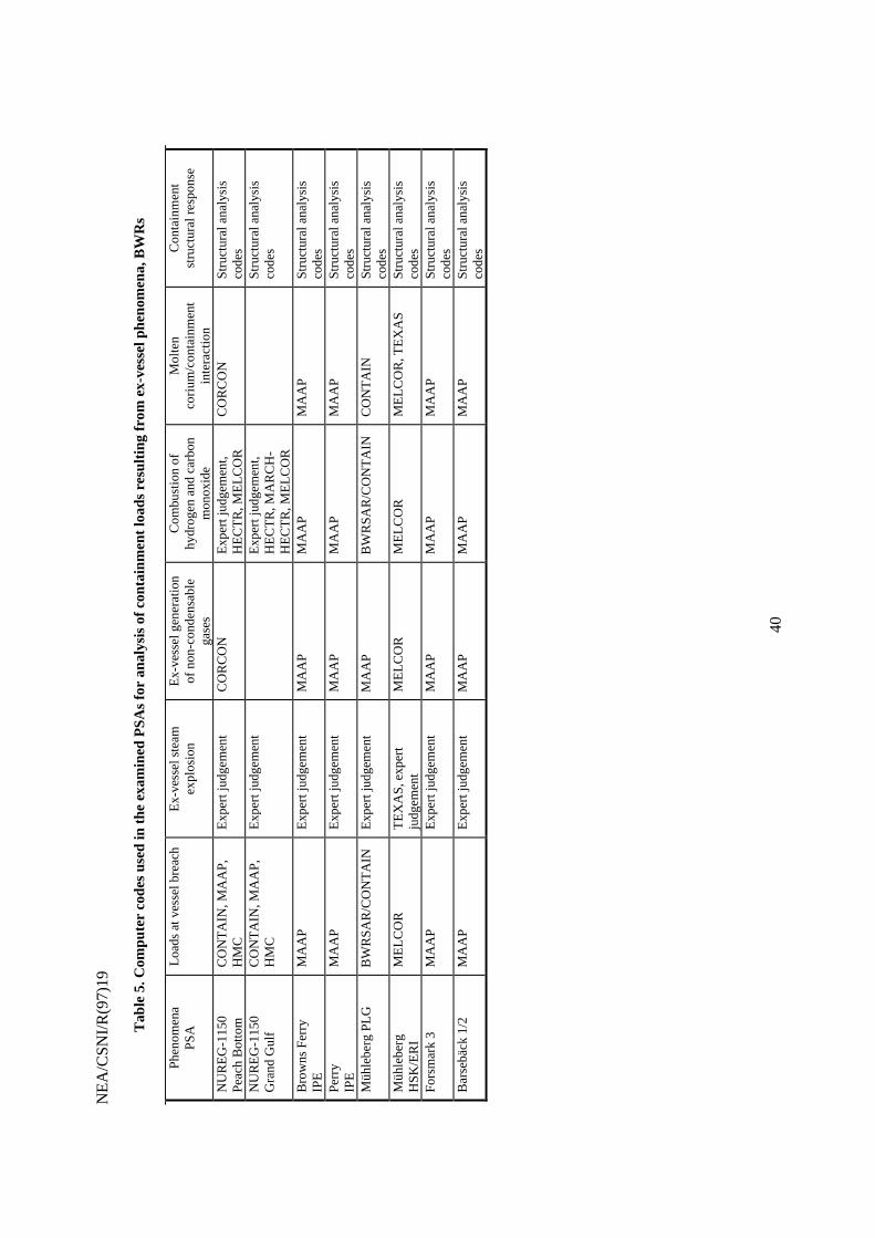
Tab
le 5
. Com
pute
r co
des
used
in th
e ex
amin
ed P
SA
s fo
r an
alys
is o
f con
tain
men
t loa
ds r
esul
ting
from
ex-
vess
el p
heno
men
a, B
WR
s
Ph
en
om
en
aP
SA
Load
s at
ves
sel b
reac
hE
x-ve
ssel
ste
ame
xplo
sio
nE
x-ve
ssel
gen
erat
ion
of
no
n-c
on
de
nsa
ble
gase
s
Com
bust
ion
ofhy
drog
en a
nd c
arbo
nm
onox
ide
Mo
lten
coriu
m/c
onta
inm
ent
inte
ract
ion
Con
tain
men
tst
ruct
ural
res
pons
e
NU
RE
G-1
150
Pea
ch B
otto
mC
ON
TA
IN, M
AA
P,
HM
CE
xper
t jud
gem
ent
CO
RC
ON
Exp
ert j
udge
men
t,H
EC
TR
, ME
LCO
RC
OR
CO
NS
truc
tura
l ana
lysi
sco
des
NU
RE
G-1
150
Gra
nd G
ulf
CO
NT
AIN
, MA
AP
,H
MC
Exp
ert j
udge
men
tE
xper
t jud
gem
ent,
HE
CT
R, M
AR
CH
-H
EC
TR
, ME
LCO
R
Str
uctu
ral a
naly
sis
code
s
Bro
wns
Fer
ryIP
EM
AA
PE
xper
t jud
gem
ent
MA
AP
MA
AP
MA
AP
Str
uctu
ral a
naly
sis
code
sP
erry
IPE
MA
AP
Exp
ert j
udge
men
tM
AA
PM
AA
PM
AA
PS
truc
tura
l ana
lysi
sco
des
Müh
lebe
rg P
LGB
WR
SA
R/C
ON
TA
INE
xper
t jud
gem
ent
MA
AP
BW
RS
AR
/CO
NT
AIN
CO
NT
AIN
Str
uctu
ral a
naly
sis
code
sM
ühle
berg
HS
K/E
RI
ME
LCO
RT
EX
AS
, exp
ert
judg
emen
tM
ELC
OR
ME
LCO
RM
ELC
OR
, TE
XA
SS
truc
tura
l ana
lysi
sco
des
For
smar
k 3
MA
AP
Exp
ert j
udge
men
tM
AA
PM
AA
PM
AA
PS
truc
tura
l ana
lysi
sco
des
Bar
sebä
ck 1
/2M
AA
PE
xper
t jud
gem
ent
MA
AP
MA
AP
MA
AP
Str
uctu
ral a
naly
sis
code
s
NE
A/C
SN
I/R(9
7)19
41
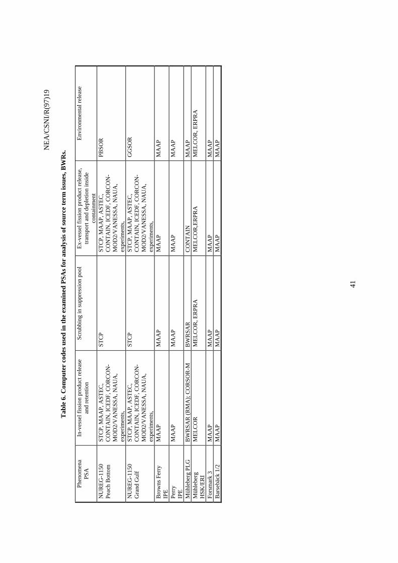
Tab
le 6
. Com
pute
r co
des
used
in th
e ex
amin
ed P
SA
s fo
r an
alys
is o
f sou
rce
term
issu
es, B
WR
s.
Ph
en
om
en
aP
SA
In-v
esse
l fis
sion
pro
duct
rel
ease
an
d r
ete
ntio
nS
crub
bing
in s
uppr
essi
on p
ool
Ex-
vess
el f
issi
on p
rodu
ct r
elea
se,
tra
nsp
ort
an
d d
ep
letio
n in
sid
eco
ntai
nmen
t
Env
ironm
enta
l rel
ease
NU
RE
G-1
150
Pea
ch B
otto
mS
TC
P, M
AA
P, A
ST
EC
,C
ON
TA
IN, I
CE
DF
, CO
RC
ON
-M
OD
2/V
AN
ES
SA
, NA
UA
,ex
perim
ents
,
ST
CP
ST
CP
, MA
AP
, AS
TE
C,
CO
NT
AIN
, IC
ED
F, C
OR
CO
N-
MO
D2/
VA
NE
SS
A, N
AU
A,
expe
rimen
ts,
PB
SO
R
NU
RE
G-1
150
Gra
nd G
ulf
ST
CP
, MA
AP
, AS
TE
C,
CO
NT
AIN
, IC
ED
F, C
OR
CO
N-
MO
D2/
VA
NE
SS
A, N
AU
A,
expe
rimen
ts,
ST
CP
ST
CP
, MA
AP
, AS
TE
C,
CO
NT
AIN
, IC
ED
F, C
OR
CO
N-
MO
D2/
VA
NE
SS
A, N
AU
A,
expe
rimen
ts,
GG
SO
R
Bro
wns
Fer
ryIP
EM
AA
PM
AA
PM
AA
PM
AA
P
Per
ryIP
EM
AA
PM
AA
PM
AA
PM
AA
P
Müh
lebe
rg P
LGB
WR
SA
R (
RM
A);
CO
RS
OR
-MB
WR
SA
RC
ON
TA
INM
AA
PM
ühle
berg
HS
K/E
RI
ME
LCO
RM
ELC
OR
, ER
PR
AM
ELC
OR
,ER
PR
AM
ELC
OR
, ER
PR
A
For
smar
k 3
MA
AP
MA
AP
MA
AP
MA
AP
Bar
sebä
ck 1
/2M
AA
PM
AA
PM
AA
PM
AA
P