Embed Size (px)
Citation preview
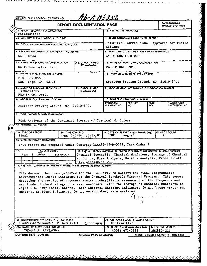
SECURITY CLASSFICATION 0': THIS PAGE
IREPORT DOCUMENTATION PAGE 001011 o. 0 706" l8e* '.'aRPOT EURITY CLASSIFIC.ATION Ib RESTRICTIVE MARKINGS
S'Unclassified24. SECURITY CLASSIFIC.ATION AUTHORITY 3 .OISTRIBUTION/AVAlLABlLfl-Y OF REPORT
2b. OECLASSIFIC.ATION /DOWNGRADING SCI4EDULE Unlimited Distribution. Approved for PublicReleaseI
A PERFORMING ORGANIZATION REPORT NUMBER(S) 5- MONITORING ORGANIZATION REPORT NUMBER(S)
GA-C 18564 SAPEO-CDE--I S-87009
6a. NAME OF PERFORMING ORGANIZATION 6bOFIESMO 7aNAEFMNTRNGRAIZIN
GA Technologies, Inc. jE-P mlbei
6C. ADDRESS (City, State, AM ZIP Code) 7b. ADDRESS (City. Start, and ZIP Code)
P.O. Box 85608 Aede v. G ~2005uSan Diego, CA 92138 AednProvng Ground,1D 00-5u
Ba NAME OP FUNDING /SPONSORING 5b OFFICE SYMBOL 9. PROCUREMENT INSTRUMENT IDENTIFICATION NUMBERORGANIZ-ATION (It applfcabiv)
PEO-PM Cml Demil I8C. ADDRESS (Crty, State, AMd 21t'Code) W0. SOURCE OP FUNDING NUMBERS
PROGRAM PROJECT TASK WORK UNITAberdeen Proving Grcund, MD 21010-5401 ELEMENT NO. NO. NO- cassION NO
11. TITLE (Dncjud* Secuntvy Oanificaton)
Risk Analysis of the Continued Storage of Chemical Munitions12. PERSONAL AUt'4OR(SI
"13&. TYPE OP REPORT 13b. TIME COVERED 14, DATE OP REPOT (YearDontk'aDoy) i.PAGE COUNTFinal P ROM 2/3/86 TOS!ZS!8 7 1987 August 433
16- SUPPLEMENTARY NOTATION
This report was prepared under Contract DAAA15-85-D-0022, 'Task Order 7
17. COSATi CODES Is. SLIrECT TERMS (Coftfnue an MWeers f neC&nary and identif by bilock number)FIELD GROUP SUB-GROuP Chemical Stockpile, Chemical Munitions, Storage of Chemical
I Munitions, Risk Analysis, Hazards Analysis, ProbabilisticlBS TACT IRisk Assessment Z~-19, BTRC (Corntiu on mvovwr if neconary and idntify by biock number)
This document has been prepared for the U.S. Army to Support the Final Progra~mmaticEnvironmental Impact Statement for the Chemical Stockpile Disposal Program. This reportdescribes the results of a comprehensive probabilistic assessment of the frequency andmagnitude of chemical agent release associated with the storage of chemical munitions ateight U.S. Army installations. Both internal accident initiators (e.g., human error) andextern'iJ accident initiators (e.g., earthquakes) were analyzed.
20 D!5TPIIUUTI0N/AVAIL-A9ILIT-y OF ABSTRACT 21. ASISTRACT SECURITY CLASSIFICATION
P - . 0 UNCLASSIFIED/UNLIMITED M SAME AS RPT C3 OTIC USERS Unclassified* *ý". .22a. NAME OP RESPONSIBLE INDIVIDUAL 22b TELEPHONE (bicIdwe Area Code) i 2c. OFFICE SYMBOL-
* ~**'~ hOAS . ARTCIA(301) 671-3325 AM PL-g* DID Form 1473, JUN U6 Nyvwotn edtloi are obsiodete. SECURITY CLaSIFICAMIN OF THIS PAGE
A
GA-C18564
RISK ANALYSIS OF THECONTINUED STORAGE OF
CHEMICAL MUNITIONS
IT '; •.: '.
byGA TECHNOLOGIES INC. , ......
"S° i A. *,*.../
I-.... -
Prepared under ...
Contract DAAA15-85-D-0022/0007for the U.S. Army
Office of the Program Executive Officer -Program Manager for Chemical Demilitarization '
Aberdeen Proving Ground, Maryland
GA PROJECT 3813AUGUST 1987
".-•<;-.5'
ACKNOWLEDG1IENT
This report is a team effort of the GA Technologies Inc. (GA)
staff, H&R Technical Associates, Inc., JBF Associates, Inc., and
Battelle-Columbus Division. Principal technical contributors are:
GA H&R
A. W. Barsell D. Crenshaw-Smith
E. A. Bellis G. J. Malek
C. A. Bolig W. R. Rhyne
R. K. Deremer R. J. Robinette
C. J. Everline P. J. Simpkins
A. J. Fraissinet
D. M. Ligon .71!
W. S. Robison D. j. Campbell
M. G. Stamatelatos
D. Tow I*ttelle
B. J. Bell
S. E. kurseITE. R. ZameJc
The project team thanks many other contributors Lot the least of
which was Jen Lobner and the technical editors and typing staff. GA :4
project managemnt was provided by H. C. Carney and M. G. Stamatelatos.
The project team greatly appreciates the review and involvement by the
Office of the Program Executive Officer-Program Manager for Chemical :1Demilitarization, personnel of the Environmntal, Safety and Surety, and
Engineering and Technology Divisions, as well as by the MITRE Corpora-""Ntion and Oak Ridge National Laboratory. ;
r.2
C.'
F:.• I .'. . % - ' " "" '" " ° . . . . . . ' % % " % % % =• " -" m5 % -% • . . "% •'
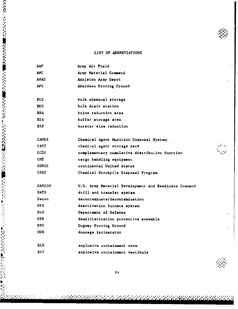
LIST OF ABBREVIATIONS
AF Army Air Field
AMC Army Material Command
kNAD Anniston Army Depot
APG Aberdeen Proving Ground
BCS bulk chemical storage
BDS bulk drain station
BRA brine reduction area
BSA buffer storage area
BSR burster size reduction
CAMDS Chemical Agent hunition Disposal System
CASY chemicel egent "torage yard
CCDF complementary cumulative distribu'•ion function
CHE cargo handling equipment
CONUS continental United States
CSDP Chemical Stockpile Disposal Program
DARCOM U.S. Army Materiel Development and Readiness Comand
DATS drill and transfer system
Decon decontaminate/decontaminat ion
DFS deactivation furnace system
DoD Department of Defense
DPE demilitarization protective ensemble
DPG Dugway Proving Ground
DUN dunnage incinerator
ECR explosive containment room
ECV explosive containment vestibule
iv
S. . . o - *..\ra%,..,...~....
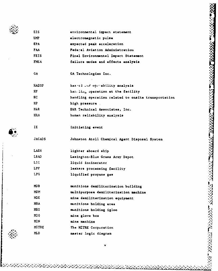
EIS environmental impact statement *
EM? electromagnetic pulse -
EPA expected peak acceleration
FAA Fede-al Aviation Administratiou
FEIS Final Environmental Impact Statement
FMEA failure modes and effects analysis
GA GA Technologies Inc.
HAZOP haz-r . td op.-ability analysis
HF han 'Li 6 operation at the facility
HC handling operation related to onsite transportation
HP high pressure
H&R H&R Technical Associates, Inc.
HA human reliability analysis!
IE initiating event P
ILJACADS Johnston Atoll Chemical Agent Disposal System
LASH lighter aboard ship ,5
LBAD Lexington-Blue Grass Army Depot
LIC liquid incinerator
LPF leakers processing facility
LPG liquified propane gas
MD)B munitions demilitarization building"I
1DIA mu-ltipurpose demilitarization machine
MDE mine demilitarization equipment
MHA mniitions holding area
MHI Innitione holding igloo
MIG mine glove box
MIN mine machine
MITRE The MITRE Corporation
MLD master logic diagram 5
v
I
S. . . . . . . " ,
MhI Modified Mercalli Intensity
MPF metal parts furnace
NA not applicable
NAAP Newport Army A-mition Plant
NDC National Destruction Center
NOAA National Oceanic and Atmospheric Administration
NRC Nuclear Regulatory Conmission
OFC offaite transport container-r
ONC onaite transport container
OPMCM Office of the Program Manager for Chemical Munitions
ORNL Oak Ridge National Laboratory
PAS pollution abatement system
PBA Pine Bluff Arsenal
PEO-PM Cml Demil Program Executive Officer-Program Manager for ChemicalDemilitari•zaton " j .
PI periodic inspection
PM periodic maintenance IPMD projectile/mortar disassembly
PRA probabilistic risk assessment [1PUDA Pueblo Depot Activity
RDC Regional Destruction Center
PIDS rocket drain system
RSM rocket shearing machine
SAI Science Applications International Corporation
SEAOC Structural Engineers Association of California
SKI storage monitoring inspection
SNL Sandia National Laboratory
SSE safe shutdown earthquake
SSI safety in :torage inspection
ST spray tank
vi
•,":, ".". -•,'.' . ./ ?".;"2.'" ; .;;-'; ,' :?-', . ;. .•''; ." .?.",:, : -- " " .". ":-. - . --;. . .: " " , - " '•" .": ,
TC ton container
TEAD Tooele Army Depo....
TECOM Test and Evaluation Command
THEEP Technique for Hunmn Reliability Analysi.
TOX toxic cubicle
UBC Uniform Building Code .
UMDA Umatilla Depot Activity
UPA unpack area
*1
I
viV
S!vii
I. •€
.•,.
CONTENTS
ACKNOWLEDGEMENT . .. .. .. .. .. .. .. .. .. . . . . .
LIST OF ABBREVIATIONS ..................... ivn"EXECUTIVE SU104AY . . .. . . . . . . . . . . . . . . . . . . . S-1 i
1. INTRODUCTION . .. . ..... . ... . . . . . . . .. 1-1
1.1. Background . . . . . . . . . . . . . . . . . . . . . 1-1
1.2. Study Objectives and Scope . . . .......... 1-6
1.3. Demilitarization Activities and Safety Concerns 1. -8
1.4. Study Assumptions . ..... ...... . . 1-10
1.5. Report rormat . . . . . . . . . . . . . . . . . . . 1-11
1.6. References . . . . . . . . . . . . . . . . . . . . . 1-14
2. RISK ASSESSMENT METHODOLOGY ......... .................. 2-1
2.1. Overview ........................................ 2-14: 2.2. Initiating Events ................................ 2-4
"2.3. Scenario Developument and Logic Models . . . . . . . 2-5
2.4. Human Factors .. ... .. .. .. .. ... . . . 2-12
2.5. Release Characterization .... .............. ... 2-13
2.6. Uncertainty Analysis ........ ................ .. 2-15
2.7. References ............ ..................... .. 2-19
3. CONTINUED STORAGE DESCRIPTION OVERVIEW ... .......... .. 3-1
3.1. Collocation Disposal Activities and Risks ..... 3-i
3.1.1. Storage ......... .................. .. 3-1
3.1.2. Handling .......... ................ .. 3-2
3.2. Munitions Description ...... ............... .. 3-2
3.2.1. Rockets* ......... .................. .. 3-2
3.2.2. Land Mines .................... . . . . 3-3
3.2.3. Projectiles and Mortars ............ .. 3-3
3.2.4. Bombs ................. ................... 13-33.2.5. Spray Tanks. ............ ................ 3.-4
3.2.6. bulk Agent ............. ................ 3-4
I" ix
/i
4. INITIATING EVENTS . .. . ... . . .. .. .. . .. . .. 4-1 "
4.1. Initiating Event Identification and Selection . . . 4-1
4.2. Initiating Event Frequencies .... ........... ... 4-11
4.2.1. External Events . . . ......... . 4-11
4.2.2. Internal Events ........ ................ 4-36
4.3. References ............ .................... . .. 4-38
5. SCENARIO LOGIC MODELS FOR STORAGE ................. 5-1
5.1. Scenario List and Event Trees ... ........... .. 5-1
5.2. External Events ........... .................. .. 5-14
5.2.1. Tornadoes and High Winds . . . . ..... 5-14
5.2.2. Meteorite Sttikes .... ............. .. 5-25
5.2.3. Aircraft Crashes ..... ............. .. 5-27
5.2.4. Earthquakes ........ ............... .. 5-35
5.2.5. Lightning ....... ................. .. 5-44
5.2.6. Floods ............. ................ .. 5-46
5.2.7. Electromagnetic Radiation ........... .. 5-50
5.3. Special Handling Activities ..... ............ 5-51
5.3.1. Leaking Muinitions . ........... .5-51 . .. 15.3.2. Human-Error Probability Estimation .... 5-55
5.3.3. Surveillance and Maintenance Activities . 5-60
5.4. Scenario Quantification ...... .............. .. 5-68
5.5. Uncertainty Analysis ........ ................ .. 5-95
5.5. 1. Overview ........ ................ ... 5-95
5.5.2. Error Factors ..... ............... .. 5-95
5.6. References ............ .................... ... 5-98
6. QUANTIFICATION BASES .... ................... .. 6-1
6.1. Handling Accident Data ....... ................. 6-1
6.2. Human Factors Data ....... ................. ... 6-3
6.3. Refezences .............. .................... .. 6-9
7. AGENT RELEASE CHARACTERIZATION ...... ............. .. 7-1
7-1. Release Analysis Approach and Bases ........ .. 7-1
7.1.1. Approach ................ ......... 7-1
7.1.2. Mechanical Failure Release .......... .. 7-2
7.1.3. Detonations ........ ................ .. 7-6
SC.- . ' ,
-. ,
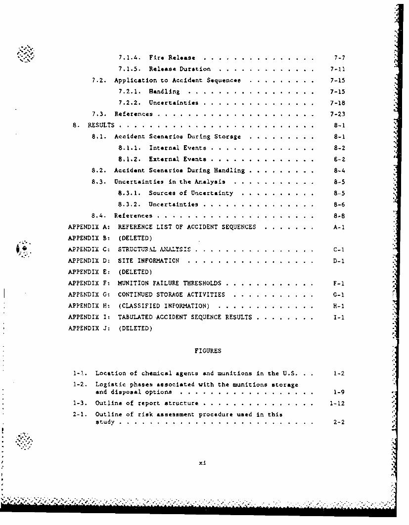
7.1.4. Fire Release . 7-7
7.1.5. Release Duration ............. 7-11
7.2. Application to Accident Sequences ... ........ .. 7-15
7.2.1. Handling ........ ................. .. 7-15
7.2.2. Uncertainties ...... ............... .. 7-18
7.3. References ........... ..................... .. 7-23
8. RESULTS ......... .................. ............... 8-1
8.1. Accident Scenarios During Storage ... ....... .. 8-1 N
8.1.1. Internal Events ...... .............. 8-2
8.1.2. External Events .............. .. -2 --
8.2. Accident Scenarios During Handling . . . . ..... 8-4
8.3. Uncertainties in the Analysis .......... ........... 8-5
8.3.1. Sources of Uncertainty ........ .......... 8--5
8.3.2. Uncertainties ...... ............... .. 8-6
8.4. References ........... ..................... ... 8-8
APPENDIX A: REFERENCE LIST OF ACCIDENT SEQUENCES ............ A-i
APPENDIX B: (DELETED)
APPENDIX C: S TRU C UP'L INZALY S'I S.. .. ............................. C-1
APPENDIX D: SITE INFORMATION ........ ................. .. D-1
APPENDIX E: (DELETED)
APPENDIX F: MUNITION FAILURE THRESHOLDS .... ............ .. F-I
APPENDIX G: CONTINUED STORAGE ACTIVITIES ... ........... .. G-I
APPENDIX H: (CLASSIFIED INFORMATION) ..... ............. .. H-I
APPENDIX I: TABULATED ACCIDENT SEQUENCE RESULTS .... ........ I-I
kPPENDIX J: (DELETED)p.
FIGURES
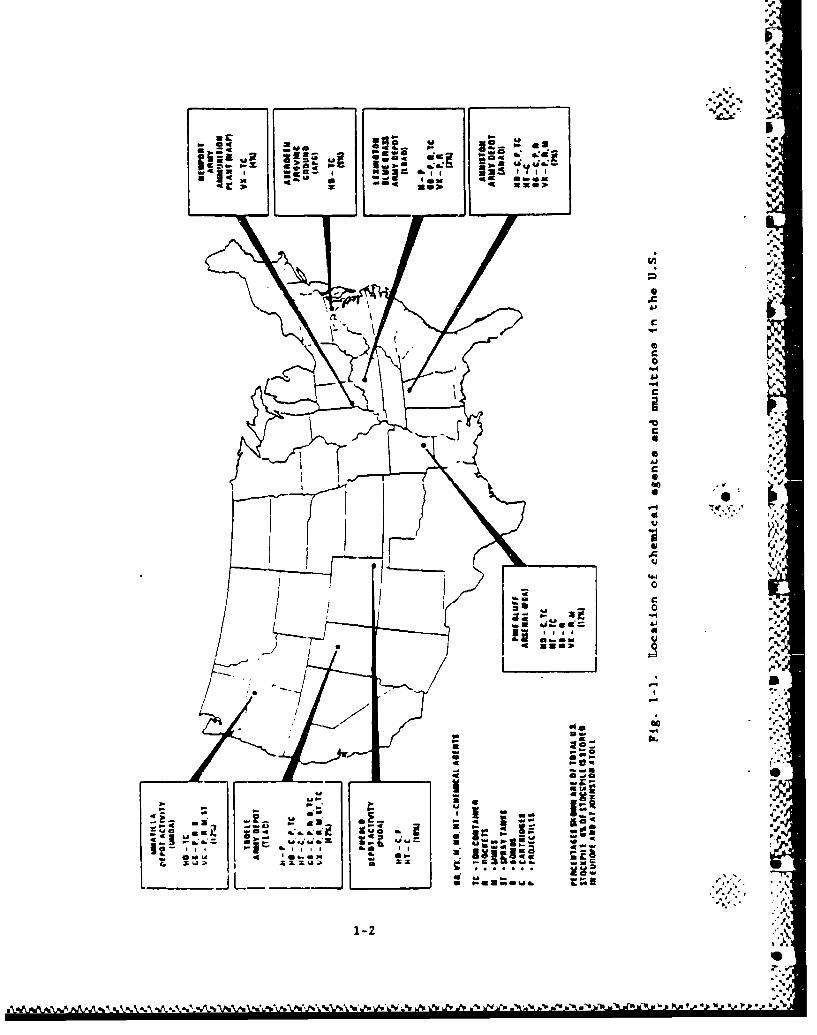
I-1. Location of chemical agents and munitions in the U.S. 1-2 ..
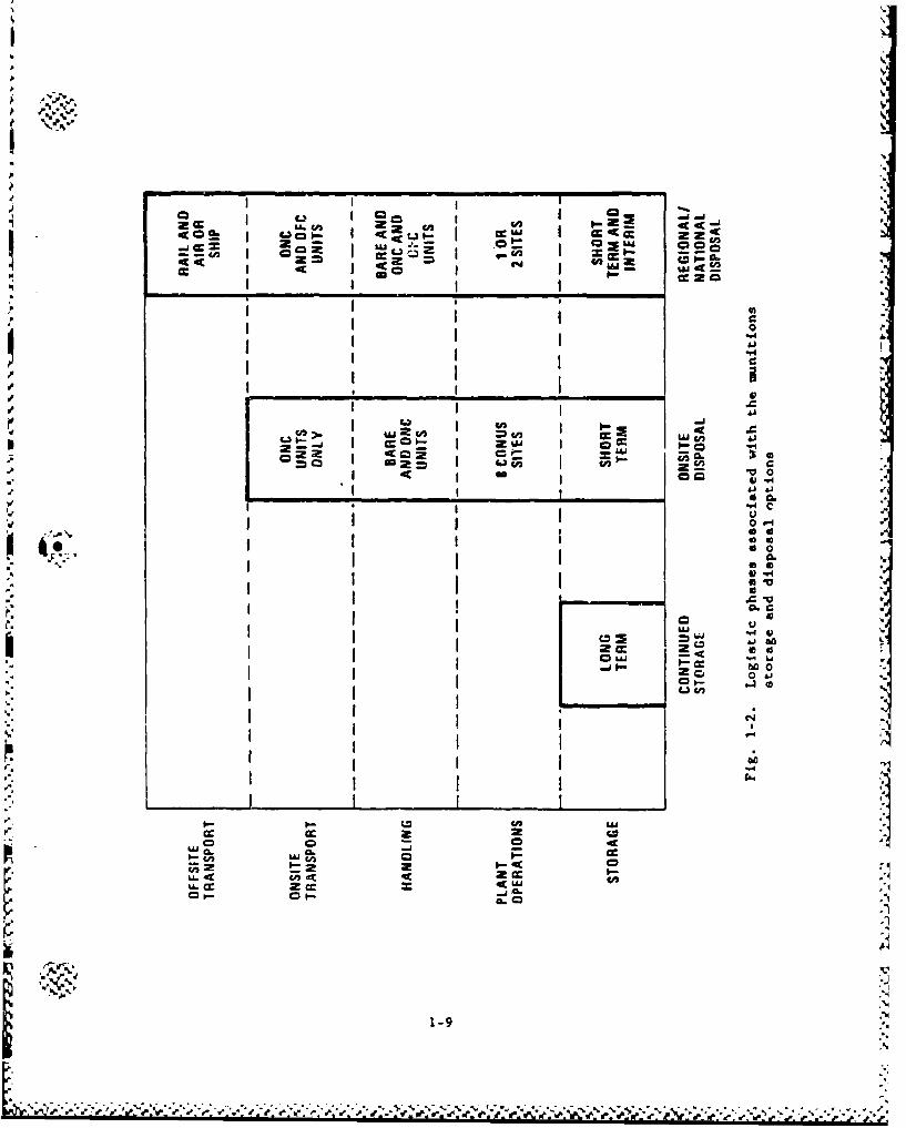
1-2. Logistic phases associated with the munitions storageand disposal options .......... .................. .. 1-9
1-3. Outline of report structure ..... ............... .. 1-12
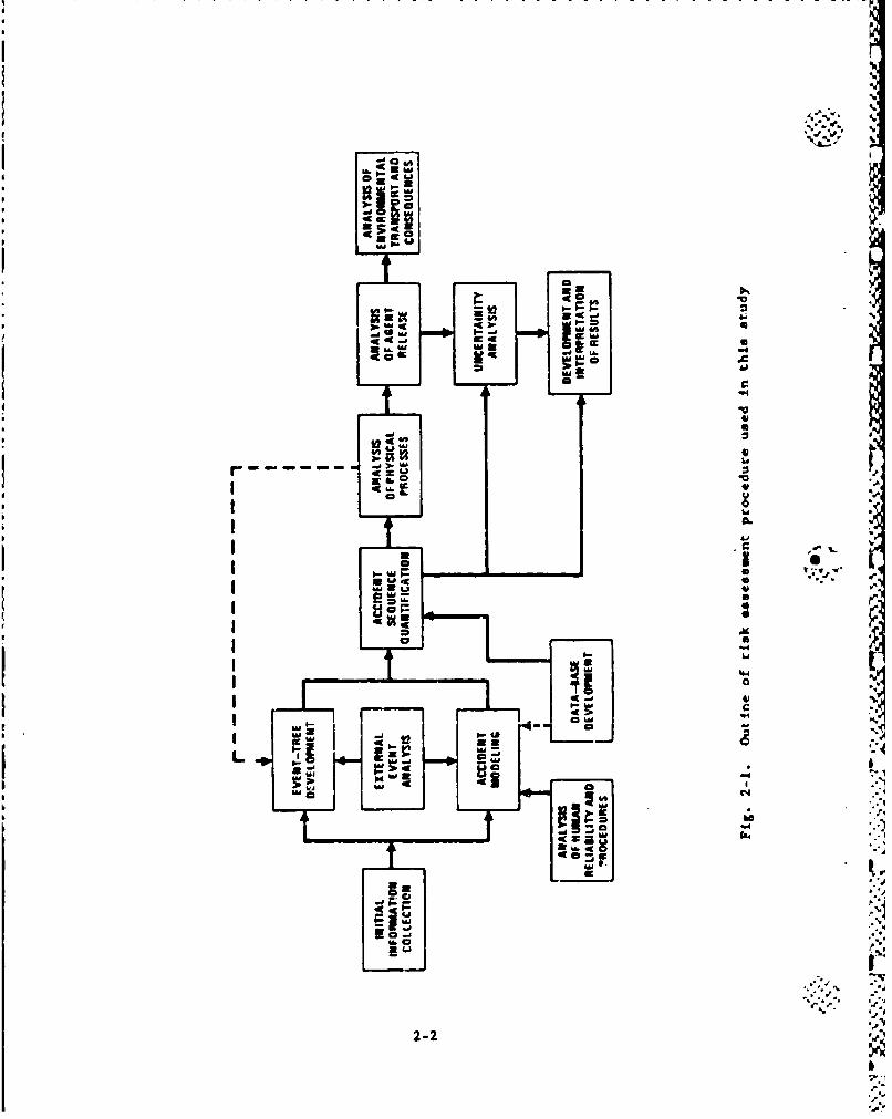
2-I. Outline of risk assessment procedure used in thisstudy ..... ......... ........................... ... 2-2
Xi%
p i,
FIGURES (Continued) ,,•
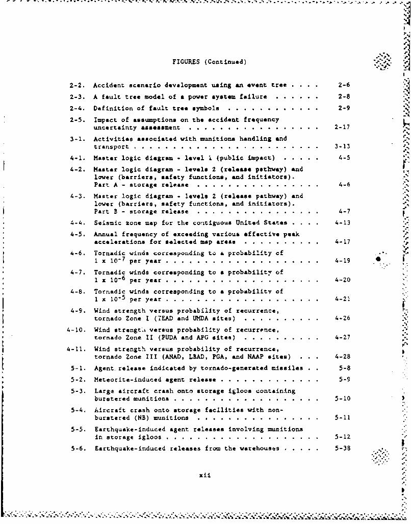
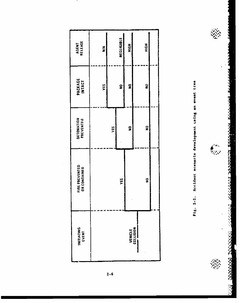
2-2. Accident scenario development using an event tree . . .. 2-6
2-3. A fault tree model of a power system failure ..... .. 2-8
2-4. Definition of fault tree symbols ... ............ .. 2-9
2-5. Impact of assumptions on the accident frequencyuncertainty assessment ........ ................. .. 2-17
3-1. Activities associated writh munitions handling and
transport ............... ........................ .. 3-13
4-1. Master logic diagram - level 1 (public impact) ...... 4-5
4-2. Master logic diagram - levels 2 (release pathway) andlower (barriers, safety functions, and initiators).Part A - storage release ........ ................ .. 4-6
4-3. Master logic diagram - levels 2 (release pathway) andlower (barriers, safety functions, and initiators).Part B - storage release ........ ............... .. 4-7
4-4. Seismic zone map for the contiguous United States .... 4-13
4-5. Annual frequency of exceeding various effective peakaccelerations for selected map areas ... .......... .. 4-17
4-6. Tornadic winds correspondizig to a probabllty of -1 x 10⁻⁷ per year .................... 4-19
4-7. Tornadic winds corresponding to a probability of1 x 10.6 per year ......... .................. .. 4-20
4-8. Tornadic winds corresponding to a probability ofI x 10.5 per year ............. ................. .. 4-21
4-9. Wind strength versus probability of recurrence,tornado Zone I (TEAD and UNDA sites) .. ........ .... 4-26
4-10. Wind strengt.a versus probability of recurrence,tornado Zone II (PUDA and APG sites) ... .......... 4-27
4-11. Wind strength versus probability of recurrence,tornado Zone III (ANAD, LBAD, PGA, and NAAP sites) . . . 4-28
5-1. Agent release indicated by tornado-generated missiles . 5-8
5-2. Meteorite-induced agent release .... ............. ... 5-9
5-3. Large aircraft crash onto storage igloos containingburstered munitions ......... ................... .. 5-10
5-4. Aircraft crash onto storage facilities with non-burstered (NB) munitions ........ .............. .. 5-11
5-5. Earthquake-induced agent releases involving munitionsin storage igloos ........... .................... .. 5-12
5-6. Earthquake-induced releases from the warehouses .... 5-38......53
xii
• '""" "' " " " " "- " € -" " --- " -"-" -" "."... .• -'2 ,'¢ e'e' '-'.". ".'".-z'4 ¢'- ," ,. .I
FIGURES (Continued)
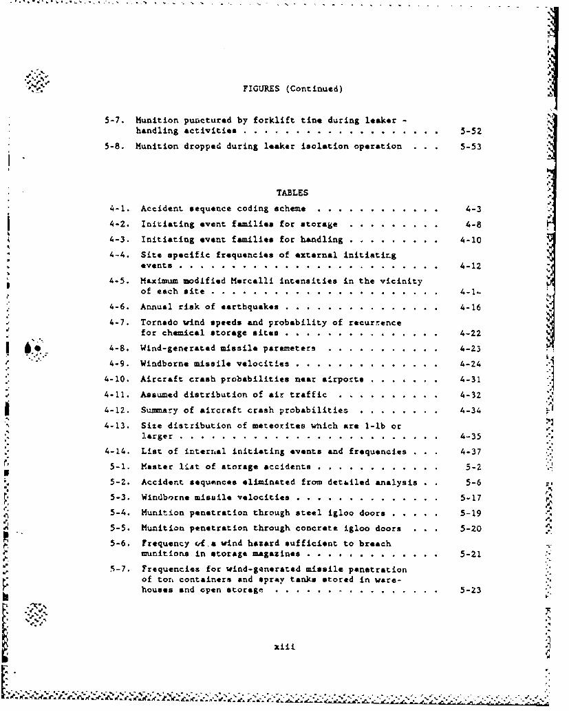
5-7. Munition punctured by forklift tine during leaker -
handling activities ............. .................. . . 5-52
5-8. Munition dropped during leaker isolation operation 5-53-53
TABLES
4-1. Accident sequence coding scheme ... ............ .. 4-3
4-2. Initiating event families for storage ... ........ .. 4-8
4-3. Initiating event families for handling ............ .. 4-10
4-4. Site specific frequencies of external initiatiLgevents ............... ......................... 4-12
4-5. Maximum modified Mercalli intensities in the vicinityof each site ............. ...................... .. 4-1-
4-6. Annual risk of earthquakes ..... ............... ... 4-16
4-7. Tornado wind speeds and probability of recurrencefor chemical storage sites . ... ............... .. 4-22
I '. ..4-8. Wind-generated missile parameters........ ........ 4-Z3. 4-9. Windborne missile velocities .... .............. ... 4-24
4-10. Aircraft crash probabilities near airports ....... ... 4-31
4-11. Assumed distribution of air traffic ................ 4-32
4-12. Summary of aircraft crash probabilities .. ........ .. 4-34
4-13. Size distribution of meteorites which are 1-lb orlarger ............... ......................... .. 4-35
4-14. List of internal initiating events and frequencies . . . 4-37
' 5-1. Master list of storage accidents ..... ......... . .. 5-2
5-2. Accident sequences eliminated from det&iled analysis . . 5-6 -,
5-3. Windb',rne misuile velocities .... .............. ... 5-17
5-4. Munition penetration through steel igloo doors ...... 5-19
5-5. Munition penetration through concrete igloo doors . . . 5-20 Ir
5-6. Frequency c.a- wind hazard sufficient to breache munitions in storage magazines . . . ....... ............ 5-21
5-7. Frequencies for wind-generated missile penetrationof tort containers and spray tanks stored in ware-
houses and open storage ........ .............. .. 5-23
xiii
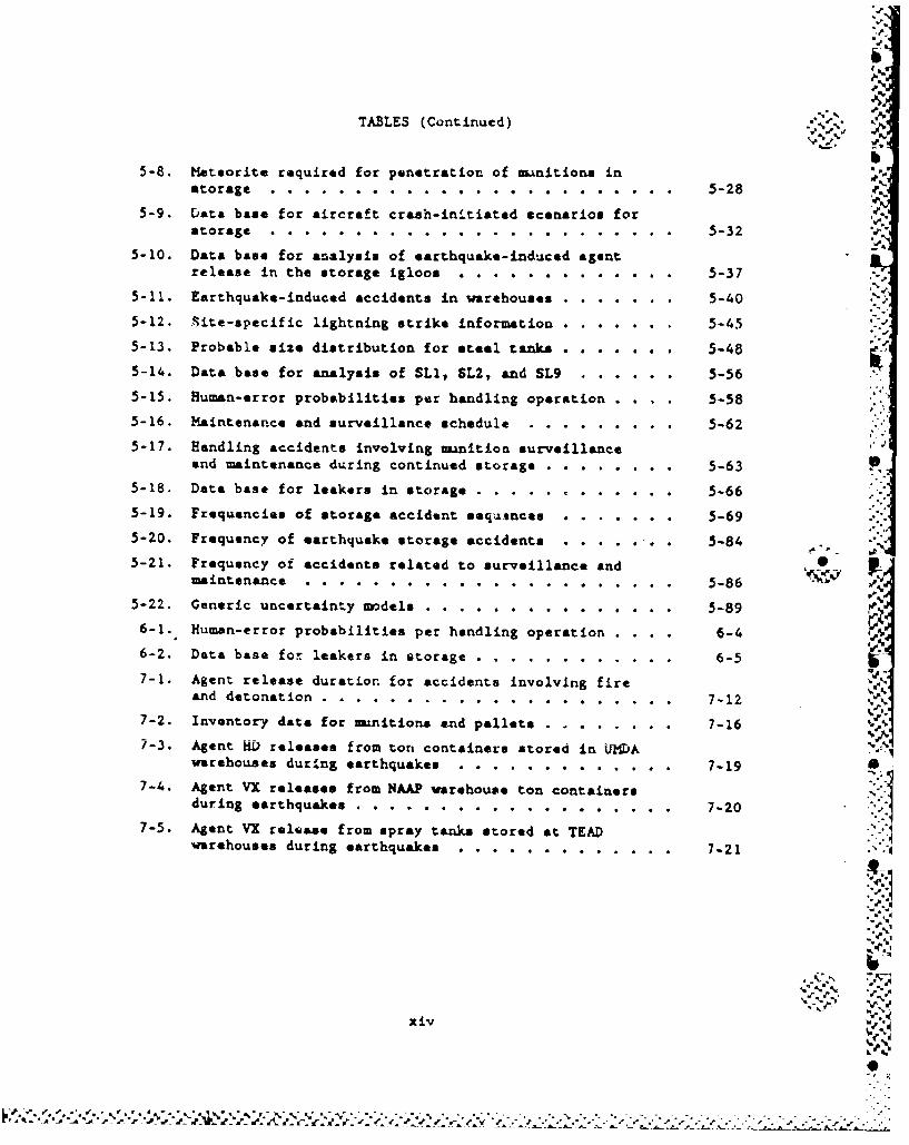
TABLES (Continued) *.\
5-8. Meteorite required for penetration of -nitions in Poatorage . . . . . . . . . . . . . . 5-28
5-9. Data base for aircraft crash-in-tiatod scenarios forstorage ................ ........................ .. 5-32
5-10. Data base for analysis of earthquake-Lnd-ced agentrelease in the storage igloos ............. 5-37
5-11. Earthquake-induced accidents in warehouses ....... ... 5-40
5-12. Site-specific lightning strike information . ...... 5-4.5
5-13. Probable size distribution for steel tanks . ...... 5-48
5-14. Data base for analysis of SLU, SL2, and SL9 ...... .. 5-56
5-15. Human-error probabilities per handling operation 5-58
5-16. Maintenance and surveillance schedule ... ....... .. 5-62
5-17. Handling accidents involving munition surveillanceand maintenance during continued storage .......... .. 5-63 S
5-18. Data base for leakers in storage ..................... 5-66
5-19. Frequencies of storage accident seq4mnces.. ....... ... 5-695-20. Frequency of earthquake storage accidents . . . . . .. 5-84 . -
5-21. Frequency of accidents related to surveillance andmaintenance ............ ...................... .. 5-86 s - %
5-22. Generic uncertainty models ..... ............... ... 5-896-1. Human-error probabilities per handling operation . . . 6-4
6-2. Data base for leakers in storage ... ............ .. 6-5
7-1. Agent release duration for accidents involving fireand detonation ........... ..................... ... 7-12
7-2. Inventory data for munitions and pallets .......... ... 7-167-3. Agent HD releases from ton containers stored in U-fDA
warehouses during earthquakes .... ............. .. 7-19
7-4. Agent VX releases from NAAP warehouse ton containersduring earthquakes ......... ................... ... 7-20
7-5. Agent VX release from spray tanks stored at TEADwiarehouses during earthquakes .... ............. .. 7-21 .
-,. .'_4
xiv.N
.- % -
Uc~rrivTIE SMlMARY
S.1. INTRODUCTION
S.1.1. Backaround
Under the direction of the U.S. Army Office of the Program Execu-
tive Officer-Program Manager for Chemical Demillitarisation (PEO-PM Cml
Demil), GA Technologies Inc. (GA) and its subcontractors performed a
comprehensive assessment of the frequency and magnitude of accidental
agent releases associated with various alternatives under consideration
for the Chemical Stockpile Disposal Program (CSDP). Thir asessment was
carried out in support of the environmental impact statement (EIS) for
this program and addresses only the stockpile of chemical munitions that. Fis currently stored at eight sites in the continental United States
(CONUS). The assessment of potential health consequences to the public
resulting from accidental releases calculated in ýhis study will be
performed in a separate study. These consequences and the GA-evaluated
fr, quencies of the releases leading to these consequences will form the
basis of estimates of the potential public "risks" associated with the
CSDP alternatives.
The alternatives inveat'gatad in, thl: :tudy are r.- follow-;
1. Disposal of the agents and munitions at the eight existing
storage sites.
2. Collocation (transportation) and disposal of the munitiona at
two regional sites.
S-1" .4
s-i;
K7: I-,
N 0
3. Collocation and disposal of the mnitions at a single national
site.
4. Partial collocation of the selected stockpiles from Aberdeen
Proving Ground (APG) to Johnston Island by water or to Tooele
Army Depot (TEAD) by air and from the Lexingtou-Blue Grass
Army Depot (LBAD) to TEAD by air.
5. Continued storage of the mu.nitions at the existing storage
site&.
This report addresseo only the continued storage alternative listed
above (i.e., item 5). The other alternatives are discussed in separate
reports.
S.1.2. Study Obiectives and Deliverables
The primary objectives of the study reported in this 4ocU"Cant W-Le
to:
I. Identify events that could initiate the release of agent to
the environment (i.e., initiating events).
2. Develop the various sequences of events resulting from these
initiators and leading to accidental agent release.
3. Perform a quantitative analysis of the frequency of occurrence
of each relevant accident sequence.
4. Characterize the physical state, quantity, and duration of
agent released from each accident sequence.
These objectives were accomplished by developing a list of poten-
tial accident sequences for each major activity, estimating the frequen-
cies of these sequences, and calculating the magnitudes of released ,4- i
S-2
b..
II
agent associated with these sequences. It should be noted that only
accident 3oquencCs that survived a conservative screening process, con-
sidering both frequency and magnitude of agent release, are included in
the deliverables of this project.
S.1.3. Scove of Study
The scope of effort reported in this document, as noted earlier,
did not include the evaluation of agent dispersion to the environment
and the consequences to the public resulting from such releases. As
such, the title of this report is more appropriately that of a probabi-
listic *release" analysis as opposed to a probabilistic 'risk" analysis,
since risk is usually defined as the product of frequency and conse-
quence. Therefore, the term 'risk," as used in this study, refers to
the frequency of accidental agent release and not to the frequency of
the agent release consequence to public health.
S.1.4. Site Descriptions
Thnae are eight sites in the CONUS where chemical munitions are
currently being stored. These sites are: Tooele Army Depot (TEAD),
Anniston Army Depot (ANAD), Aberdeen Proving Ground (APO), Lexington-
Blue Grass Army Depot (LBAD), Newport Army Aw-inition Plant (NAAP), Pine
Bluff Arsenal (PBA), Pueblo Depot Activity (PUDA), and the Umatilla
Depot Activity (UMDA).
TEAD is located in north central Utah. A prototype demilitariza-
tion plant, the Chemical Agent Munitions Disposal System (CAMPS) facil-
ity, is located at this site. The site currently stores a wide variety
of chemical munitions and bulk agent containers of mustard and the nerve
agents, GB and VX.
%i
S -3
- . - - --- . . . . . .- . .
ANAD is located in northeast Alabama. The chemical umunitions
stockpile at ANAD consists of all chemical rnnitions types except for
bombs, spray tanks, and 8-in. projectiles filled with VX.
APG is located in Haryland near the head of the Chesapeake Bay.
APG is comprised of tw general areas, the Aberdeen area and the
Edgeowod area where the chemical munition storage facilities are
located. Only wuastard-filled ton containers are stored at APG.
LBAD is located south of Richmond, Kentucky. The chemical muAnition
stockpile at LBAD consists of 8-in. projectiles, 155-rn projectil•es and
M55 rockets.
NAAP is located west of Indianapolis, Indiana. The chemical mani-
tions stockpile is stored there in a single warehouse and consists of
containers of VX.
PBA is located southeast of Little Rock, Arkansas. The stockpile bat PBA consists of H55 rockets, land mines, ton containers, and some
4.2-in. mortar projectiles. ',-'
UMDA is located in northeastern Oregon. The stockpile at UIDA
consists of 155-mm and 8-in. projectiles, M55 rockets, H23 land mines,
bombs, spray tanks, and ton containers.
S.2. STUDY APPROACH
The risk analysis presented in this report combines the structured .
saftty analysis detailed in HIL-STD-882B (Ref. S-i) and the probabilis- .
tic approach outlined in NUREG/CR-2300 (Ref. S-2). The first reference
requires that hazards analyses be performed to aseess the risk involved
during the planned life expectancy of a system. It also provides guid-
ance on the categorization of hazard severity and of probability as a
means of identifying which hazards should be eliminated or reduced to an
S# -.4S-• "r."--
0 •'
acceptable leval. The second reference serves as a guidebook for the "
risk assessment of nuclear power plants.I
Risk assessment can be defined as the quantification of an undesir-
able effect in probabilistic terms. Relative to the health and safety
of the public, the effects of interest are injuries and deaths. Risk
assessment. has been utilized in various industries for some time.
Insurance companies have long used actuarial data for statistical eva-
luations to justify differences in the insurance premium paid by persons
in different "risk" categories. The risk cs-ments performed for
nuclear pover plants, on the other hand, are examples of major industry
efforts to quantify risks of low-frequency events for which no good
actuarial data exist. The nuclear power plant risk assessments have
become mdels for other industrial risk assessments.
S.2.1. Risk Assessment Methodology
Probabilistic risk assessment (PRLA) is a systematic, disciplined
approach to quantifying the frequency and consequences of events which
can occur at random points in time. In its application to the various
chemical munition disposal alternatives currently under consideration,
PRA provides a comprehensive framework for estimating and understanding
the risks associated with the storage, handling, transportation, and
demilitarization activities associated with thcse alternatives. By
applying this methodology to each alternative in a consistent and uni-
form manner, a statement of the relative risk of these alternatives can
be made. Because of the significant uncertainties in the data used to
quantify the frequency of occurrence of various accident sequences and 4the magnitudes of the associated agent releases, extreme caution must be
used when addressing the absolute risk associated with each disposal
option.
5'.9.
S -5
In simplistic terms the PRA process focuses on answering the fol- ••
loving three basic questions:
1. Wh.t can go wrong?
2. How frequently is it expected to happen?
3. What would be the associated consequences?
The remainder of this summary describes how these questions are
addressed in the risk assessment of the chemical materiel disposal pro-
gram. In this study, the estimation of consequences is limited to the
magnitudes of agent release for each sequence.
S.2.1.1. Identification of Initiatint Events. The first step in a pro-
babilistic risk assessment is the identification of initiating events
which, by themselves or in combination with additional failures, can
lead to the release of agent to the environment. Initiating events are
identified for each of the demilitarisation activities. Such events
generally fall into two broad categories known &a *internal" events and 0"%external" events. Internal events originate within the activity and ' .
Pe
are caused by human error or random equipment failure. Examples of such
events are the dropping or puncture of uanitions during handling opera- Y
tions, and the random failure of a normally operating piece of equipment
in the demilitarization process line. The class of events referred to
as external includes aircraft crashes and natural phenomena such as
carthquakes and storE. In tlh context of a &isk &**easo-nt, eventssuch as internal flooding and fires are also considered to be &xternal
events. External events are usually pervasive in nature in that they
are assue-d to fail redundant equipment that is provided for safe shut-
down of the operation and containment of the agent.
S.2.1.2. Accident Sequence Development. Once initiating event. are
identified, logic models (such as event trees and sequence level fault
tree.j) are developed to display the various paths that the accident can
take. For axaj'-L, an initiating eveut such an upuri.us shutdown of an
S-6
'r
-~. . .*pI r_ e.,* . . r- e- r, a,# 0 1 PI d aN F P AI &F 4 0 . V W6 W I. ir,
9..
incinerator will not result in a significant release of agent to the
environmsnt unless numerous ventilation and automatic shutdown systems
fail. In most cases, the probability of failure of multiple systems is
so low that the frequencies of such accident sequences are too low to be
of any concern. Furthermore, because of inherent system inertia and
engineered safety features which are provided, there may be ample timeto recover and repair mitigating* system prior to any release.
As suggested above, operator intervention can influence the course
of an accident, and therefore his role must be included in the logic
models where appropriate. Of course, operating and emergency personnol
also have a significant influence on the potential for and amount of
accidental agent release.
S.2.1.2. Human Interactions. Human interactions, or intervenLions, of
interest to the chemical munitions disposal risk assessment fall into
one of the following six general categories:
1. Initiation of an accident by committing an error (e.g., a
munitions handler punctures or accidentally drops a munition).i~".
2. Test and maintenance actions (e.g., a valve is disabled or
left in the wrong configuration following a test or mainte-
nance act).
3. Termination of an accident by correctly implementing estab-
lished emergency procedures (e.g., an operator terminates
agent feed to the liquid incinerator wher. automatic termina-
tion has failed).
4. Aggravation of an accident by taking incorrect action (e.g.,
a plant operator misdiagnoses the r"ature of the accident and
KMitigation" as usad in this report is the act of preventing orlimiting the consequence of an accident that has occurred.
S-7
N. . . . . . . .*. d * 0 ~ 4N t w ~ * * **r C . A~t. .~.. - . . 4 r-. * *J
performs an act which causes the accident to have greater ,
cons~equences).
5. Tezmination of an accident by actions which are outside the
scope of existinS procedures (e.g., based on his knowledge of
the plant or process, a plant operator performs en act which
is not covered by procedures and terminates or mitigstas the
&ccident).
6. Intentional acts to initiate accidents or render equipment in
a failed state (sabotage).
Human interactions that fall in the first three categories are
modeled either as a separate event heading in the event tree or as an
independent event in the fault tree which is used to model and quantify
the event in the event tree. Human interactions defined by categories 4 4and 5 above are difficult to quantify and as such are not given much
attention in a risk assessment. '
Acto of sabotage (category 6) are outside the scope of this analy-
sis and will be addressed elsewhere.
S.2.1.4. Agent Release Characterization. the consequences of an agent-
release event are dependent on the type of agent, the magnitude of the
release, the mode and duration of the release, the dispersion of the
agent to the environment, the demographic characteristics of the region
impacted by the release, and the toxicity of the dispersed agent at the
concentration levels to which members of the public are exposed. The
scope of effort reported in this document is limited to the first three
characteristics listed above. Agent dispersion to the environment and
subsequent effects on humans are addressed elsewhere in a separate
report.
* .. o .
S-8
'-) "A"' "-~i I- A--P1,0 jI - 'P lo** " '. "-!J -P- - - F rW,-r-r--C,-r
b
The characterization of agent release required a systematic review
of the potential modes of agent release from its normal confinement.
The agent release mechanism is dependent on the particular mechanical,
thermal, and explosive behavior of the znition, assuming the occurrence
of an initiating event such as dropping during handling or aircraft
crash, as well as the confinement which is provided, if any.r
After determining that agent could be released in a particular
accident sequence and that the frequency of that sequence axceeded the
threshold screening frequency, an analysis was performed to identify the
possible paths by which the agent could be released to the environment
and to estimate the quantity of agent released.
S.2.1.5. Sequence Screening. The implementation of PRA methodology in
terms of event trees can produce a large number of potential accident
sequences. In order to reduce this to a manageable number to focus on
the critical scenarios for analysis, the accident sequences are screened
for frequency or consequence. By using conservative values for the
conditional probabilities of event tree branches, it is possible to show
that many of the possible sequences are of sufficiently low frequency
(e.g., less than I0-10 per year) that they need not be addressed
further. In addition, if an accident sequence has a frequency greater
than the threshold screening frequency but results in an insignificant
release of agent* to the environment, it can also be eliminated from
further coraideration. The accident sequences contained in this report
have been subjected t-. both types of screening.
%I*Less than 14 lbm of mustard; less than 0.4 lbm of agent VX; and
less than 0.3 ibm of agent GB. These quantities represent the minim•mquantities of agent release that wuld result in a lethal dose of agentat 500 m for the most limiting release modes (Ref. S-3).
S-9
0. Ov dv
S.3. RESULTS L AThe analysis of the potential for agent release to the atmosphere
from a&cident scenarios related to the continued storage alternative
included storage and handling activities. This section discusses some
of the accident probability and agent rela"s results associated with
these activities.
The results of the analysis of the various activities encompassing
the continued storage alternative cannot be presented in the same units,
i.e., annual frequencies, because of the possible divulgence of clas-
sified information. This is only possible for some storage accident
scenarios. For accident scenarios related to the handling activities,
the unclassified portion of the probabilistic analysis is given in terms
of frequency of accidents per pallet of minitions (or as a container ofmni*ntions).
The evaluation of the actual risk to the public and environment 0
requires agent dispersion calculations which are not in the scope of the
study reported here. Despite this limitation, the results discussed
herein still provide useful insights on the contributions of the various
disposal activities to the risk of an agent release. These insights are
discussed below.
S.3.1. Accident Scenarios During Stocage
The continued storage alternative requires some storage of muni-
tions in their existing location.
S.3.1.1. Internal Events. There were no significant internal event
initiators of accidents during storage. Per unit operation, forklift
drop accidents occur more frequently than forklift tine punctures.
Also, the use of a lifting beam instead of a tine leads to an order of
m=gnitude decreasc in drop frequency.
S-10
' -f :• ,I v X ?,• -, *( ,_ • . =* .. ... *.-o.-. • .. =...•. ° .** .-. - . -,-. ..-.- %'**. *.- . - . - - - - . .. . ..7
A.
•,.J S.3.1.2. External Events. These events involve accidents caused oy
natural phenomena or human activity affecting r•uitions in storage
igloos, open storage areas, holding areas, or warehouses. If these a&'e
"assuled to be full of u•iitions, the agent inventories range up to 100,
200, 1000, and 2000 tons, respectively, for mtorage igloos, bolding
areas, open areas, and warehouses. The most frequent external accidunts
having significant release involve mild intensity earthquakes or small
airplane crushes (order depending on site). Amounts of available agent
inventories released in these events are on the order of fractions of
one percent or less (munition punctures, drops, etc.).
The largest releases occur for a large aircraft crash, a meteorite
strike, or a severe earthquake, especially when a warehouse (at NAAP,
TEAD, or UHDA) is involved. These can result in up to 10 percent of
the agent inventory released for scenarios involving a fire which has
the potential (duration) for destroying ;he entire inventory of an igloo
or warehouse. The munitions stored in warehouses contain only VX or
,�,.' mustard which have much slower evaporation rates than GB and hence are -
not easily dispersed into the atmosphere. Thus, warehojue scenarios U
involving only spills are not significant -ýisk contributors. The ware-
house at UMDA has the potential for the largest release. Meteorite
strike-initiated sequence median frequencies are one to tw orders of |
magnitude lower than the aircraft crash-induced sequence frequencie3.
As expected, munitions stored outdoors are generally wore susceptible to
large aircraft crashes than t.hos! stored in warehouses or igloos, but
releases are lower. Both APG and '&/. have ton cortainers stored out- 1doors, and the aircraft crash probabilities at these sites are somewhat
higher than at the other sites. Igloos appear to provide only minimal
protection from dicect crashes of large planes, but releases are an
order of magnitude lower. The releases arm wore severe if burstered "•
munitions are involved.
%.
S-1A-
s..lo
S.3.2. Accident Scenarios During Handling a•". .. "
Included In the handling analysis are ainglo munition or pallet.,•
movtments by hand, forklift, or other equipment. .
'p
The results indicate that dropped mutritions, whether in pelletized
form or not, occur more frequently than either forklift tint puncture or
forklift collisioi-, accidents. In fact, the frequency of forklift colli- :.
C.o
sion accidents which lead to th a m tions falling off the forklift is *.
an order of magnitude lower than the drop &ccidents, Furthermore, thetype of clotuhing an operator is wearlng while hdling these monrtlonsl
influence the drop frequency value. An operator wearing Level A cloth-.-'ing is more likely to cormi.t an error that would cause the .unition to
be d:opped than nen hte is t-harong more uint.crtable w lothingi l"
For bare cunrtions, the rockets seem to h e frhk most prone to punc- or
furei from drops or forkliftrklif Lcc-dents.
Bulk items that are punctured liad to iarg of releases than otherrklt
munitions such an projectiles or roc.kets. Bo)mbs are of concern becausethey contain GB which evaporates more readily tdan the other agent
typesf The agent vapor releases range up o 170 lib (thermal failure of
all muanitions in a pallet).
Handling accidents which lead to significant agent releases (in -i
particular, agent GB) are dominant risk contributors because of therelatively higher arual frequency values. Of course depending on theLl ct
actual d mnition inventory, the value of annual frequency may either
increase or decrease when converted to the more meaningful per stockpile
S.4. UNCERTAINTIES IN THE ANALYSIS ""
In assessing the risks associated with the CSDP alternatives, every
effort was made io perform bei ladstimaos analyses, i.e., *realiste c
S-12
bai
S.12-0 -,
.- . " -.-- S '- * ' " , ' -,- *"" " - * . "S - % . - ' ." " .- -- .- " . '' . --: - .-- -- ' '- ;. . - -" .. "---. .- : - .
N
evaluation and quantification of the accident sequence frequencies and
associated agent releases. The use of pessimistic or conservativeI
modeling techniques or data for quantification violates the intent of
the probabilistic nature of the study. Realistic modeling and qu~ar.i-
fication permits a balanced evaluation of risk contributors and compari-
son of alternatives. However, for realistic or best-estimate calcula-
tions, the obvious concern is the accuracy of the results. Uncertainty
analysis addresses this concern.
S.4.1. Sources of Uncertainty
Since the event sequences discussed in Section S.3 have not
actually occurred, it is difficult to establish the frequency of the ..
sequence and associated consequences ,A.th great precision. For this
reason, many parameters in a risk asseasmant are treated as probabilis-
tically dist-ibuted parameters, so that the computation of sequence fre-
quencies and resulting consequences can involve the probabilistic combi-
nation of distributions. C.
There are three general types of uncertainty associated with the .
evaluations reported ir. this document: (1) modeling, (2) data, and
(3) completeness.
There exist basic uncertainties regarding the ability of the varl-
ous Models to represent the actual conditions associated with the
sequenct of events for the eccident scenarios that can occur in the
storage and disposal activities. The ability to represent actual phe-
nomena •ith analytical models is always a potential concern. The use of
fundamental models each as fault trees and event trees is sometimes aim-
plistic because most events depicted in these models are treated as
leading to one of two binary states: success or failure (i.e., partial
successes or failures are ignored). Model uncertainties ore difficult
to quantify and are addressed in this stiudy by legitimate efforts of the
S-:3A'
• •. :. ":
..............................- '
analsts to make the models as realistic as possible. Where such real-
ism could not be achieved, conservative approaches were taken.
No uncertainty from oversights, errors, or omission from the models
used (e.g., event trees and fault trees) is included in the uncertainty
analysis results. Including these uncertainties is beyond the state-of-
the-art of present day uncertainty analysis.
The uncertainties in the assignment of event probabilities (e.g.,
component failure rates and initiating event frequencies) are of two
types: intrinsic variability and lack of knowledge. An example of
intrinsic variability is that where the available experience data is for
a population of similar components in similar environments, but not all
the components exhibit the same reliability. Intrinsic variations can
be caused, for example, by different manufacturers, maintenance prac-
tices, or operating conditions. A second example of intrinsic variabil-
ity is that related to the effects of long-term storage on the condition
of the munitions as compared to their original configuration. Lack of 1. 6
knowledge uncertainty is associated with cases where the model parameter
is not a random or fluctuating variable, but the analyst simply does not
know what the value of the parameter should be. Both of these data
uncertainty types are encountered in this study.
S.4.2. Uncertainties
The sequence frequency results discussed in this report are pro-
sented in terms of a median value and a range factor of a probability
distribution representing the frequency of interest. The range factor
represents the ratio of the 95th percentile value of frequency to the
50th percentile (i.e., median) value of frequency. The uncertainty in
the sequence frequency is determined using the STADIC-2 program
(Ref. S-4) to propagate the uncertainties associated with each of the
events in the fault trees or event trees through to the end result.
Some scenarios, such as those associated with tornado missiles and low-
S-14
impact detonations have rather large uncertainties. The difficulty with
tornado-generated missiles lieu with the difficulty in accurately model-
ing the probability that the ,Iissile will be in the proper orientation
to penetrate the munition avd in predicting the number of missiles per
square foot of wind. The difficulty with the low-impact detonations
lies with the sparse amr.nt of data available and its applicability to
the scenarios of interest. In general, uncertainties tend to be large
when the amount of applicable data is small and vice versa.
S. 5 . REFERENCESN!
S-i. U.S. Department of Defense, "Military Standard System Safety Pro-
gram Requirements," MIL-STD-882B, March 30, 1984.
S-2. U.S. Nuclear Regulatory Commission, "PRA Procedure Guide," NUREG!
CR-2300, 1982.
S-3. Memorandum to C. A. Bolig (GA) from R. B. Perry (PEO-PM CmI
Demil), May 6, 1987.
S-4. Koch, P., and H. E. St. John, "STADiC-2, A ComputLr Program fcr
X •Combining Probability Distribution," GA Technologies Inc.,
GA-A16277, July 1983.
U.,.
""S-15.-
i=i
1. INTRODUCTION
1.1. PACKGROUND
The U.S. Department of Defense is required by Congress (Public Law
90-145) to destroy the stockpile of lethal chemical agents and murnitions
stored at eight U.S. Army installations in the continental United States
(CONUS) and at the Johnston Atoll Army site in the Pacific Ocean by the
end of September 1994. The locations of the CONUS sites are shown in
Fig. 1-1. The total Army stockpile at these sites is made up of more
than 3,000,000 items consisting of rockets, mines, mortars, projectiles,
cartridges, bombs, spray tanks, and bulk containers. These nmnitions
contain the nerve agents GB and VX and the blistering mustard agents H,
HD, and HT
The Army has developed a plan for destruction of the chemical muni-
tion stockpile. This plan is set forth in the Chemical Stockpile Dis-
posal Concept Plan submitted to Congress in March 1986 and supplemented
in March 1987. In thin plan, three disposal alternatives are describedt
1. Disposal of the agents and munitions at each of the eight
existing storage sites.
2. Collocation and dfsposal of the uminitionA at tw regional
sites.
3. Collocation and disposal of the munitions at a single national
site.
These three disposal alternatives were also described in a Draft
Progammatic Environmental Impact Statement published by the Army in
1-I
44 a W"o 1k .i.i
4b;~
W ma 49 Ox I
a 404
XZ02-
- 00-4
4-4
1-21
L
July 1986. Additionally, it was required that the status quo, i.e.,
continued storage, be also evaluated as the fourth alternative. As part
of the public co=enntary on this document, requests were made of the
Army to consider also the transport of the inventory from Aberdeen
Proving Ground to Johnston Islend by water or to Tooele Army Depot by
air and from the Lexington-Blue Grass Army Depot to Tooele by air.
Under direction from the U.S. Army Office of the Program Executive
Officer-Program Manager for Chemical Demilitarization (PEO-PM Cml
Deril), GA Technologies Inc. (GA) and other contractors have performed a
comprehensive probabilistic assessment of the frequency and magnitude of
agent release associated with activities involving the three disposal
alternatives currently set forth in the Chemical Stockpile Disposal Pro-
gram (CSDP), as wall as the continued storage alternative. This assess-
ment has been carried out in support of the environmental impact state-
ment (EIS) for this program and it addresses only the stockpile of chem-
ical munitions which are currently stored at the eight sites located in
the continental United States (CONUS).
When combined with an assessment of the consequences (injuries
and/or deaths) to the public resulting from the accident sequences and
associated agent releases identified and evaluated in this study , the
results form a basis for an assessment of public risk. The dispersion
of the agent to the environment and the assessment of consequences
related to these releases are outside the scope of this study. A conse-
quence assessment has been performed by MITRE Corporation and Oak Ridge
National Laboratory for the EIS, based on the releases identifLed in
this document.
This report addresses only the alternative of continued storage.
The remaining alternatives are discussed in separate reports.
Previous studies have been utilized by GA as reference bases for
this assessment. Quantitative hazards analyses were performed by
1-3
Arthur D. Little, Inc. on the disposal of M55 rockets (Refs. 1-1 to X
1-5), and qualitative hazards analyses were performed by the Ralph M.
Parsons Company on the Johnston Atoll Chemical ASent Disposal bystem
(JACADS) design (Refs. 1-6 and 1-7). In addition, a probabilistic anal-ysis of cheaical agent release during transport of M55 rockets has been
performed by H&R Technical Associates (Ref. 1-8), and a probabilistic
analysis of selected hazards during the disposal of H55 rockets has been
performed by Science Applications International Corporation (Ref. 1-9).
These studies provided the set of accident scenarios that was compiled
in a systematic order by ITR.E Corporation (Refs. 1-10 and 1-11). GA,
in turn, used these accident scenarios as a starting point in this
study.
The analyses performed by Arthur D. Little, Inc. used a technique
known a6 hazard and operability analysis (BAZOP). HAZOP invclves a
detailed review of plant doepig to trace all parts and functions of the
demilitarization process. For each piece of equipnint or pipe run,
deviations from normal operating conditious were examined and possible (-
consequences wire discussed. Through this approach, potential failure
modes leading to agent release outside of the facility ware identified.
The expected frequencies of occurrence of all agent release sequences
' identified in the HAZOP were then evaluated using fault tree analysis.
- The qualitative hazards analysis performed for JACADS used an
approach know. as failure modes and effects analysis (FMEA). The sever-
ity and probability levels of identified hazards were ranked according
to the guidelines in Ref. 1-12.
The transportation studies performed by H&R Technical Associates
(Ref. 1-8) used a combined fault tree and event tree approach to assess
tia frequency of agent release from transportation accidents.
.o4.
'1-
The work performed by Science Applications International Corpora-
tion (Ref. 1-9) on the disposal of M55 rockets utilized both event tree
and fault tree methodology as used in the PRA of nuclear power plants.
1-5
-;.•- -• .- - ;.- -.. . ... , . ..- - . .. .. . . ..... .. ..... , L'...... .., • .•... ... ,• ,.. . ... • .j.. . , ,• ,... ,, ,. • ,, ,4 .... ••;.\ '. ;,• •rZ'.;. .;. ? •ez _d /
1.2. STUDY OBJECTIVES AND SCOPE1, .P.'
The primary objectives of the study reported in this document were
to:
1. Identify events (for each major activity) that could initiate
the release of agent to the environment.
2. Develop the various sequences of events resulting from these
initiators and leading to agent release.
3. Perform a quantitative analysis of the frequeLcy of occurrcnce
of each relevant accident sequence.
4. Characterize the form, quautity, and duration of agent release
from each accident sequence.
5. Identify accident sequences uhich make the m-at siguificant
contributions to risk.
The major deliverables of this effort are a list of potential anci-
dent sequences for each major activity, the estimated frequencies of
these sequences, and the magnitudes of released agent associated with
these sequences. It should be noted that only accident sequences that
survived a conservative screening process, involving both frequency and
magnitude of agent release, are included in these deliverables.
This report addresses each of the objectives listed above and pre-
sents the analysis of this study. The risk analysis includes an evalu-
ation of potential accidents and natural occurring pheiomsna such as
earthquakes and tornadoes. Acts of war, sabotage, and terrorism, whichinvolve intentionally-initiated events, wre not included in the scope
of this effort.
1-6
The term "chemical munitions" is used here to describe both burst-
ered chemical munitions and chtmical bulk items. The 4.2-in. mortars
reafr to the actual 4.2-in. projectile '•hich is fired from mortar can-
nons or tubes. The 105-rn cartridge and 4.2-in. mrtar projectile can
either be configured with propellant (i.e., a cartridge) or without
propellant (i.e., a projectile)i in this study, it was assumed that the
propellant and fuze were removed prior to the onset of the disposal
program.
I'
.1
I -'
1-7 "'
"Is
s u u u u u i
Fr
V
1.3. DEMILITARIZATION ACTIVITIES AND StFETY CONCERNS
Figure 1-2 shows a comparison of the various logiLstics phases asso-
ciated with the various mnition disposal and storage alternatives eval-
uated for the EIS. As indicated in this figure, the demilitarization
process associated with the continued storage option involves only those
events related to long-term storage.
The hazards of interest are those involving the evaporative release
of agent to the environment resulting from spills, leaks, and mechanical
failures, and the release of agent to the environment resulting from
fires and explosions. The generation of these potential hazards orig-
inates with a number of *internal* and 'external* initiating events.The number of hazard-initiating event combinations is rather extensive.
However, because of the screening process which was used to remove from
further consideration the accident sequences whose frequency was low
and/or the associated magnitude of agent release was low, the number of
individual sequences which are important to risk is relatively small.
1-81
cc LA 3 '
00 I zUEC~j J i 4 J! ua ~
4z~CA'
e4C uI w
cLi
02 fnn z f
00-*0. .0
S06
IU Qcz 6U
0.I I =Ia '
Ij CDI
LA At cn IL'
. 2 c
10
1.4. STUDY ASSUM1TIONS
The risk analysis presented in this report uses an approach
that combines the structured safety analysis detailed in MIL-STD-882B
(Ref. 1-12) and the probabilistic approach used in the safety analyses
of nuclear Fower plants (Ref. 1-13). Reference 1-12 requires that haz-
ards analyses be performed in order to assess the risk involved during
the planned life expectancy of a system. It also provides some guidance
on the categorization of hazard severity and probability as a means of
identifying which hazards should be eliminated or zeduced to a level
acceptable to the managing activity.
The risk analysis was performed under the following set of general
assumptions:
1. Mtunitionrs will be scored in their current storage locations.
2. Munitions are in good condition.
3. Sabotage or terrorism is not considered.
A detailed listing and discussion of assumptions is presented in
Appendix E.
1-10
.,- .. . . ... *. .-. .. ~. a . : ,.,,.. . .* ,,* .,. - .4 . . . .. . . . .
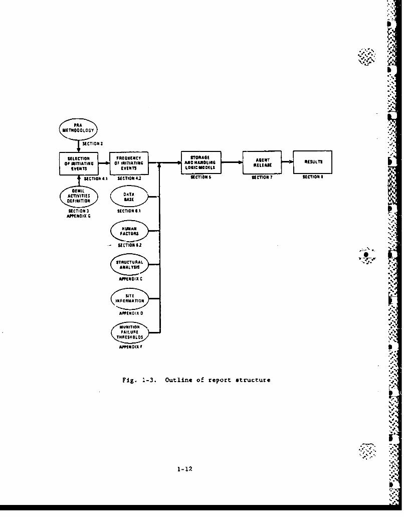
1.5. REPORT FORMAT
This report is structured as outlined schematically in Fig. 1-3.
The structure follows that typically used in comprehensive probabilistic
risk assessment (PRA) studies.
Following the introduction in Section 1 of this report, Section 2
proviides a summary of the methodology used in this assessmnt, including
the procedure for accident scenario identification and screening, the
approach used for quantifying accident frequencies and characterizing
agent release, and the treatmet of uncertainties.
Section 3 provides a brief discussion of the vhrious activities
involved in the continued storage of chemical manitions. This discus-
sion is provided to assist readers in the understanding of the initi-
ating events and accidetit scenarios that have been identified and are
discussed in Section 5. Section 3 also discusses site-specific infor-
(0k. mation that is important to a particular site. Appendix D contains
additional site information.
The list of accident initiating events which have been analyzed isalong with the analysis of their occurrence frequencies are presented in
Section 4. These events include accidents from internal causes, such as
inadvertant impact during handling, and accidents caused by external
events, such as earthquakes or aircraft crashes.
Section 5 presents the detailed development and analysis of the keyaccident scenarios resulting from the initiating events.
Section 6 provides the basis for quantification of accident
sesqunce frequencies including munition failure probabilities, the data
base used for estimating the probabilities of event-tree top events and
fault-tree basic events, and the data used for assessing human error. I.--
6 -Wa I
Vb
PRAT
S ECTION 2 RECUEN 6.1
AP9EN:AGENT
OF INITIATING OF INITIATING AN HANLINEREULT
EVENTS EVENTS LOGIC MODELSREAS
SUECTION 3 SECTION 1.1APPENDIX G
"-
4.-LYSS
A P P E N DO I X C . •
Tt"
APPENDIX 0 e%-
M .
APPEND IX F I:-".
Fig. 1-3. Outline of report structure :... -
1.1
•,.2- ' .5•,•--
"-4 "^ : .'
1 - 12 ,..-5
I)* ,-'.5 _J
* %:p.
The characterization of agent released in the varl .us accid.ent
sequences is discussed in Section 7.
Section 8 presents the overall results of the analysis.
Supporting data and calculations for the study are contained in the
appendices. References to appropriate appendices are made throughout
the body of the report.
to, I
I-
.4
'.4
1-13
- .4
%I
1.6. REFERENCES
1-1. Arthur D. Little, Inc., "Analysis of Risks Associated with
Operation of Onsit. M55 Rocket Demilitarization Plants," U.S.
Army Toxic and Hazardous Materials Agency, M55-OD-3, May 1985.
1-2. Arthur D. Little, Inc., *Analysis of Risks Associated with
Operation of the JACADS M55 Rocket Demilitarization Plant," U.S.
Army Toxic and Hazardous Materials Agency, M55-OD-9, May 1985.
1-3. Arthur D. Little, Inc., "Analysis of Converted M55 Rocket
Demilitarization Plant at Pine Bluff Arsenal," U.S. Army Toxic
and Hazardous Materials Agency, H35-OD-10, May 1985.
1-4. Arthur D. Little, Inc., "Analysis of Risks Associated with
Operation of the CAMDS M55 Rocket Demilitarization Plant," U.S.
Army Toxic and Hazardous Materials Agency, M55-OD-11, May 1985.
1-5. Arthur D. Little, Inc., "M55 Rocket Separation Study," U.S. Army
Toxic and Hazardous Materials Agency, M55-OD-08, November 1985.
1-6. The Ralph M. Parsons Company, "JACADS-PrelimLnary Hazards Analy-
sis of Final Concept Design," Tasik 0-56 Interim Report: May 1983.
1-7. The Ralph M. Parsons Company, "Fault Tree Analysis, Johnson Atoll
Chemical Agent Disposal System," Task G-SC, U.S. Army Engineers
Division, February 1985.
1-8.' Rhyne, W. R., et al., "Probabilistic Analysis of Chemical Agent
Release During Transport of M55 Rockets," H&R Technical Asso-
ciates, Inc., Prepared for USATHAMA, M55-CD-4, H&R 255-1,
September 1985.
1-9. Science Applicatio". International Corporation, -Probabilities of
Selected Hazcrds in Disposition of M55 Rockets," U.S. Army Toxic
and Hazardous Materials Agency, M55-CS-2, November 1985.
1-10. Fraiz., W., ea ̂ t., "PrelimInary Risk Analysis Supporting the
Chenaisl Weapons Stockpile Disposal Program (CSDP), Volume 12
Analysis," Th* MITRE Corporation, MTR-86W4-01, May 1987.
1-11. Freize, W., at. al., "Preliminary Risk Analysis Supporting the
Chemical Stockpile Disposal Program (CSDP), Volume 21 Appen-
dices," The ?IITRE Corporation, KMR-86W4-OI, May 1987.
1-14
1-12. U.S. Department of Defense, "Hi itary Standard System Safety
Program Requirements," MIL-STD-8823, March 30, 1984.
1-13. U.S. Nuclear Regulatory Commission, 'PRA Procedure Guide,'
NUREO/CR-2300, 1982.
1-15
NI
.JJ.J
2. RISK ASSESSMENT METHODOLOGY
2.1. OVERVIEW
The probabilistic risk assessment (PRA) methodology used in this
study is generally consistent with the PRA Procedures Guide (Ref. 2-1)
for nuclear power plants. Figure 2-1, adapted from that guide, outlines
the risk assessment procedure for this study. Certain specific features
of the chemical munition accidents dictate some different emphasis and
treatments from those described in Ref. 2-1. The risk assessment steps
corresponding to the prccedures in Fig. 2-1 are as follows:
1. Identify accident initiators (initiating events) through
information collection, hazards analyses, or the use of
4•,- umster logic diagrams. The initiating events are classified
as external if they originate from outside the munition stor-
age and maintenance process (such as aircraft crash) and as
internal otherwise.
2. Define accident scenarios, i.e., combinations of initiating
events and the successes or failures of systems that respond
to the initiating event. An "accident sequence" is referred
to in this report as a specific end point of an accident sce-
nario, which is usuelly modeled using event trees. An 'event
tree" is an inductive logic model which traces the sequence of
events that can occur following an initiating event.
3. Construct "fnult trees" (deductive system logic models) to
determine the root causes of individual system failures. The
fault tree is reduced to minimal cut sets using Boolean alge-
bra. A "minimal cut set" represents s unique combination of
events leading to system failure.
2-1
W45
II.
inS
.0 Ai
a 0
U.~
"%4
2-22
Va
4. Assign failure rates or probabilities to events (components or
subsystem) modeled in the event trees and fsallt trees. Quan-
tify the frequencies of occurrence of accident sequences from
either the event tree or fault tree by computing the product
of the initiating event frequency and the probabilities of the
subsequent conditional events in a given accident scenario.
5. Determine the consequences of the accident sequences. In this
analysis, the consequence of concern is the amount of aSent
released to the local free environmnt. The impact of agent
release on the population vill be used by others in theiv CSDP
analysis.
6. Evaluate the uncertainties it the data base, and predict the
uncertainty in each relevant accident sequence frequency by
propagating the top event uncertainties through the event
trees-
.... 7. Present the results (i.e., accident scenario frequency and
consequence) in a form that will best show those sequences
that are important to risk and will reflect the uncertainties
associated with the accident sequence frequency.
""-"a.
.%
2-3
2.2. INITIATING YEENTS
An initiating event (IE) is a single occurrence or malfunction that
has the potential to release one or more agents or to start a sequence
of events that could lead to a release. The list of Is is developed
based on previous demilitarization studies (Section 1.2) and related
PRAs such as Waste Repository studies (e.g., Ref. 2-2), in addition to
the use of master logic diagram.
The IE list is developed in top-dovn fashion by structuring a mas-
ter logic diagram to define a functional set of initiating categories.
These categories form a complete set in the sense that any event which
leads to agent release must cause at least one of these categories to
occur.
Some "coumn cr use initiating events* (i-.g., an earthquake) can
activate more than one initiating event category and disable controls
for release. While there is no way to guarante. that all such events
are identified, two areas yield the most significant events. The first
includes severe environmental events (such as fire, flood, earthquake,
and wind) as wall so hazardous activities in the vicinity (such as air-
craft patterns). The second area includes malfunctions that can affect
n.ltiple control* or barriers for the prevention of release to the
atmosphere.
Coincident with the development of the list of Initiating events is
the assessment of the initiating event frequencies. This is required,
first, for subsequent quantification of event trees, since the event
initiator is the first even of the tree. Second, it enables screening
of the list of initiating events, i.e., events having extremely low fre-
quencies can be eliminated. Where possible the lEs are grouped into
categories when the oubsequent event tree and release analysis develop-
bunt is the same for all Is in the category. This grouping is per-
formed by Boolean sumnation of the occurrence frequencies, accounting
for dependencies, if any.
2-4'. '
2-4
2.3. SCENARIO DEVELOPMENT AND LOGIC MODELS
Given the occurrence of an initiating event, accident scenarios are
developed, In many cases using logic models of either event trees, fault
trees, or both, to arrive at the various outcomes of the scenario pro-
gression. Each of these outcomes, termed a sequence, is associated with
(or even characterized by) a certain level of agent release. The basic
premise of the risk sum-ation process is that release frequencies (ini-
tiating event frequency multiplicatively combined with probabilities of
subsequent failures necessary to get the release) of entirely different
sequences can be additively combined to get the overall frequency of
release. The additive and multiplicative combination is performed using
Boolean algebra and accounts for dependencies.
Figure 2-2 shows a sample event tree. In this example, the IE is a L
vehicle collision, having an estimated occurrence frequency which can be
a point estimate or be probabilistically distributed. The IE is the
first 'top event," and potential subsequent failures represent the other
"top events or branch points. These top events are in the form of ques-
tions, and by convention the upper branch represents the positive ansver
sequence and the lower branch is the negative answer sequence. Branch
split fractions or probabilities are assigned at each of these branch
pcints. These split fractions may be point estimates or probabilistic
distributions, and may not be the same for all branch points under a
specific top event, depending on prior events. That is, the split
fractions represent conditional probabilities.
The frequency of an accident sequence is calculated based on the
following equation:
n
2-5
- - .t $- .~--.--
z <MA La
L.U
416 ai
-U c>0
P- -j0 0
00.
2-6
N
A", where Fj - frequency of accident sequence J,
Ij w initiating event frequency,
Pi,j w conditional probability of sequence event i following an
initiating event, Ij.
Accident frequency and equipment/component failure rate data were
derived from various sources, as described in Section 9.
In this study, the event trees are relatively simple in form
compared to those developed for nuclear plant PRAs. host dependencies
are modeled explicitly in the event trees by use of conditional branch..
ing probabilities which are dependent upon the branch taken for prior
events. For example, in an event tree where two consecutive top events
represent the availabilities of system: 1 and 2, system 2 might not be
called upon unless system 1 fails. This would be shown in the event
tree by a dashed line for system 2 in the system 1 success branch, indi-
. cating noL applica&ble. Conversely, if system 2 is capable of operating
'sw- only in conjunction with successful operation of system 1, the dashed
line is shown on the system 1 failure (no) branch for system 2 top
event. This indicates a guaranteed failure of system 2, given nonoper-
ation of system 1.
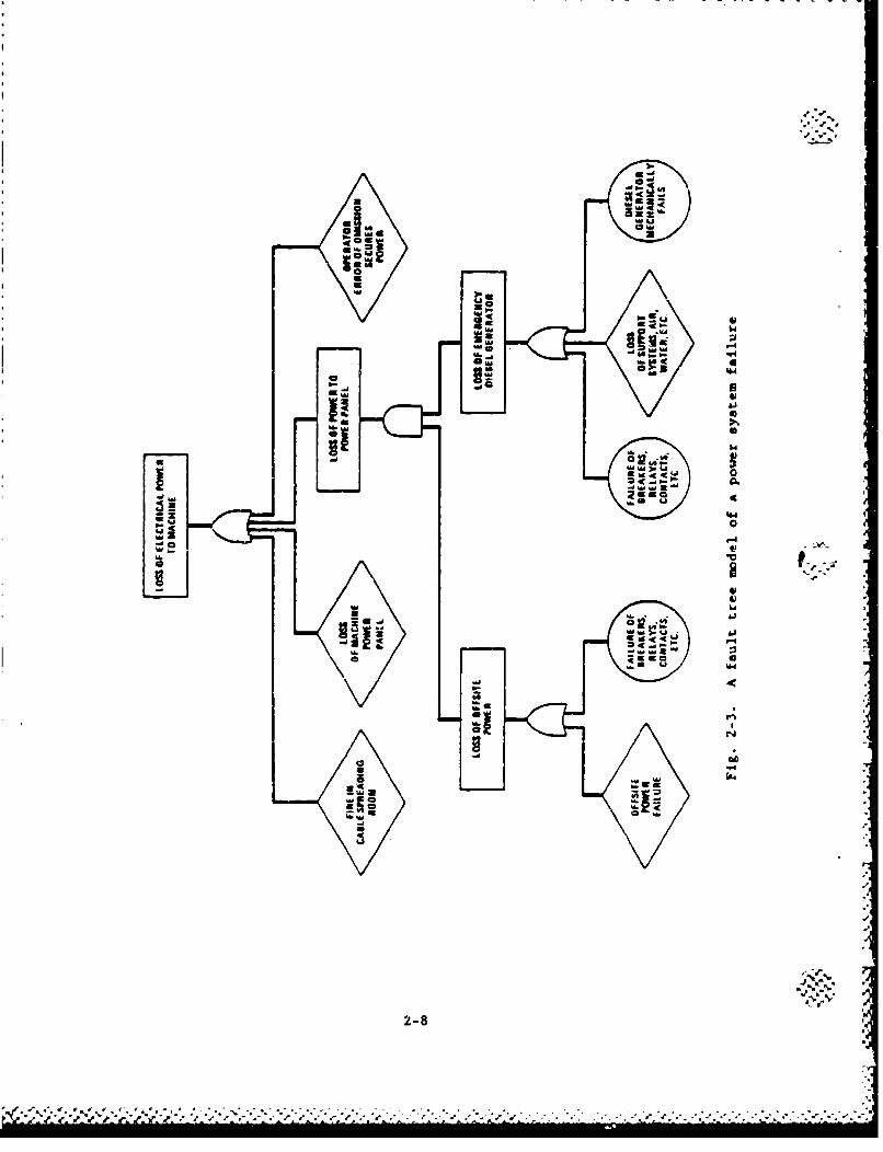
For many scenarios, it was found convenient to use fault tree
logic for development of the accident progression and quantification
of the sequence frequencies. Figure 2-3 depicts a sample fault tree.
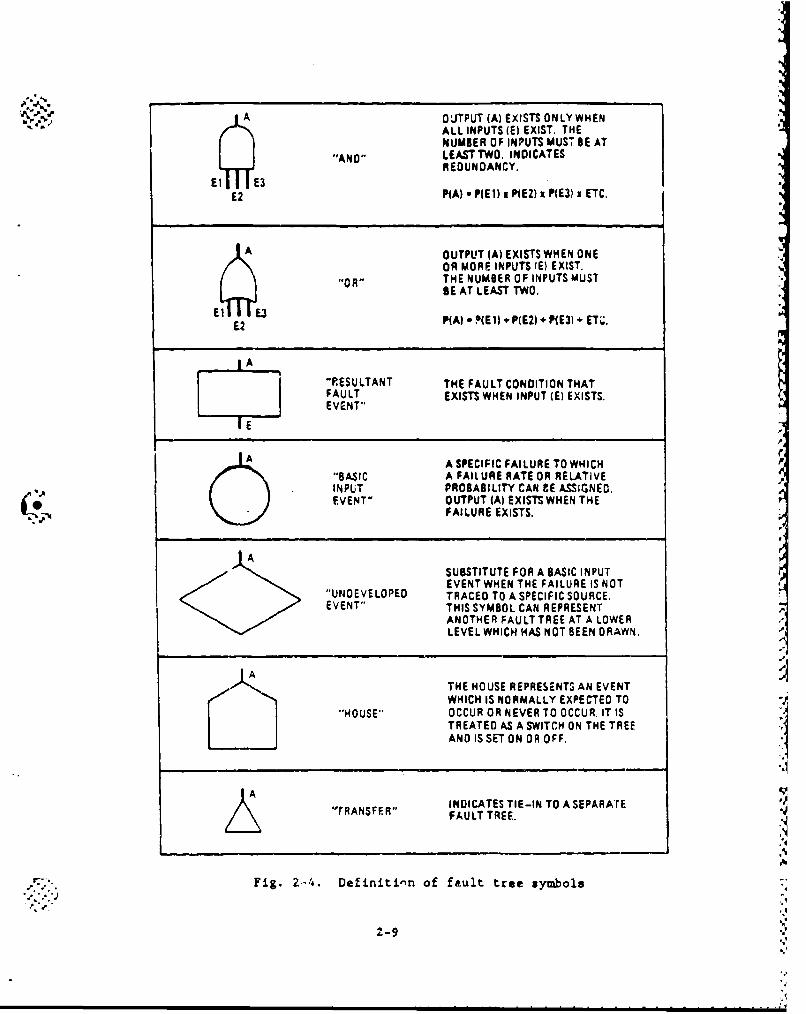
Logic symbols used in constructing fault trees are defined in Fig. 2-4.
The approach taken for treatment of dependencies in the event trees
is to identify specific intercomponent and intersystem causes of multi-
ple failures, if any, directly in the fault tree and to make an allow-
ance for those not explicitly identified. A Beta factor method (e.g.,
Ref. 2-3) is a convenient too] for determining a suitable allowance and
was used where appropriate. In this method, multiple failures of redun-
dant components are assumed to occur in a dependent fashion; the
2-7
1 *-'
Ia q w@I�e
U
0aU
UJJaU
bi
U
ii'5 0
'-4-'C5'
4
00
./
'-1**-�., 5*
2-8
C� 4 V 4 �-. 4. � -. ..----------
A OUTPUT (A) EXISTS ONLYWHEN"ALL INPUTS (E) EXIST, THENUMBER OF INPUTS MUST BE AT
"AND" LEASTTWO. INDICATESREDUNDANCY.
E2 P(A) a PME1) x P(EZ) x P(E3) x ETC.
A. OUTPUT (A) EXISTS WHEN ONEOR MORE INPUTS (E) EXIST.
"0R" THE NUMBER OF INPUTS MUSTAE AT LEAST TWO.
E2 3PA) * PNE1) * P(E2) + P(E3) + ET.
IAl "PESULTANT THE FAULT CONDITION THAT
FAULT EXISTS WHEN INPUT (E) EXISTS.EVENT"
1E"
A SPECIFIC FAILURE TO WHICH"BASIC A FAILURE RATE OR RELATIVEINPUT PROBABILITY CAN CE ASSIGNED.
1 1 EVENT" OUTPUT (A) EXISTS WHEN THEFAILURE EXISTS.
ASUBSTITUTE FOR A BASIC INPUTEVENT WHEN THE FAILURE IS NOT
"UNDEVELOPED TRACED TO A SPECIFIC SOURCE.EVENT" THIS SYMBOL CAN REPRESENT
ANOTHER FAULT TREE AT A LOWERLEVEL WHICH HAS NOT BEEN DRAWN.
THE HOUSE REPRESENTS AN EVENTWHICH IS NORMALLY EXPECTED TO
"HOUSE" OCCUR OR NEVER TO OCCUR. IT ISTREATED AS A SWITCH ON THE TREEAND IS SET ON OR OFF. IINDICATES TIE-IN TO A SEPARATrE
"tRANSFER" FAULT TREE.
-•'- Fig. 2-4. Definitinn of fault tree symbols"•'.'.''J ',
2-9"
5'
parameter P is defined as the fraction of failures experienced in .-.
c•uoa.ients that are comon cause failures.
Just as there are uncertainties in estimating component failure
rttes, there are also uncertainties in the P factor. These uncer-
tainties were quantified assuming a lognormal dintribution for the ,factor. The uncertainty distribution accounts for uncertainties due to
sparsity of data, as well as those due to classification and the so-
called 2potential comn cause failures." These are events in which one
failure actually occurs and additional failures could have occurred
under different circummtances, as mall as incipient failures and
degraded operability states.
In the case where the fault sequence i, given an initiatirg event,
involves a subsystem or equipment failure, the failure probability cal-
culations may involve not only the calculation of the unavaila:•ility
value (probability of failure per demand) but also the unreliability
valie (probability of failure while component/equipmmnt is runni.nS). In
this case, the overall failure probability value for a given equipment
or subsystem is calculated using the following equation (Ref. 2-3),
Pi "P,d + (- Pi,d) Pi,r
where Pi,d - failure upon demand (unavailability),
" failure while ruz&aing (unreliability).
The calculation of component unavailebility (Pi,d) is .. nflvenced
by several factorat (1) the frequency of periodic maintenance (PM);
(2) the use of different failure detection system ; and (3) the various
methods used to monitor equipment operation.
ror tLe analysls presented -n this report, two options were consid-
exed in the calculation of component unavailability. The first option .
is tc, curksIder the periodic malr, tannca of a cccmpient. Thý,, 4 ben a
'r.
2-LO,.U
0,component is periodically rewved from service for preventative mainrke--
nance, the failure probability is dominated by the maintenanice interval
in addition to the failure rate according to the following equations
i,r -O 0 - *-^) .t - (2-3)
where X failure rate,
B - mAintenance interval,
The second option was to consider continuous component surveillance
which decreases the failure probability by announcing component failure
to the operators concurrent with failure initiation. The repair time
required to restore the component becomes an important factor as shown
in the following equation:
iE = - l C(+V)t] (2-4)Pi~r +
"where V - 1/r mean repair rate (per h),
r - repair time (h),
t - time interval of interest (h).
In Eq. 2-4 the failure probability approaches XT as the time interval
increases and Xr is small (i.e., Xr << 1).
In most of the component failures identified in the fault tree
models, the first option is used and a monthly maintenance interval is
assumed (i.e., interval of 528 h) for the equipment. This is a conser-
vative approach in deriving the failure probabLlity. If a more frequent
maintenance policy is adopted or 1.f experience shows that the component
restoration time is much less than the maintenance interval, the failure
probability will decrease. Howver, In view of the nature of the fault
tree mdels, this approach seems Justified because the failure contribu-
tion of a particular component is not negated by assuming an unnecessar-
ily low failure probability.
2-11
2.4. HUMAN FACTORS . "
7ho treatmert of intersystem &ad intercomponent equipment depen-
dencies is discussed above, including how the dependencies are taken
into account by the logic models. This section describes another kind
of dependence--that involving human interaction.
To the extent that human beings design, construct, operate, and
maintain the plant, it is impossible to fully isolate the role of human
interactions from any of the dependencies discussed above in term of
hardware interactions. Hence, all of the common cause analysis methods
described above pertain directly or indirectly to human interactions.
The dlicussion is restrictod here to human interactions In the operation
and m&intenance processes.
The procedure for analysis of intersystem an(! intercomponent depen-
dencies caused by human interactions was to include human errors of
omission and commission explicitly in the event tree/fault tree wdels
and to use the human reliabilit7 mathods of Swain (Ref. 2-4) to iple- '-•'. g.
ment quantification. A starting point for the identification of epe-
cific errors is the analysis of operation and maintenance procedures if f
they have been defined for the event sequence being invest•gated. This
is especially importnt if operator action is required to effect actua-
tion of a system or a collection of systems. Consideration needs to be
given to possible incorrect judgments as to the plant state and subse-
quent implemnt.t.ion of tha -wrong procedures. Once thete acts are iden-
tified and modeled, the problom of determining contrdbution to risk by
operator actions is reduced to assigning the correct human error rate
values.
2-12
Al
i.,4
II
2.5. RELEASE CHARACTERIZATION
The risk aseociated vwith each accident scenario requires not only
the quantification of the frequency of that scenario but a characterisa-
tion of the agent release " well. This characterisation involves the
type and amount of agent released, plus the mode and duration of the
release.
At any given time, there is at least one containment barrier sops-
rating the agent from the surrounding environment. Thus failure or loss
of integrity of this barrier must occur for agent to be released to the
environment.
In general, the accident scenarios of intetest are rhose seonsriom
in which the agent is initially inside the munition. There are essen-
tially three types of agent release to the environment,
6" 1. Evaporation from a liquid spill.
2. Releases resulting from detonations. *r3. Releases resulting from fires.
Various combinations of these releases appear in mny of the scnaios. -
In addition, depending on the location of these eveinL (e.g., isidoot
versum outdoor spills), the evaporatiorn rates governing these release*
may vary somewhat.
The approach taken tot assessing the amount, typo, ald duratio.k of
agent release is based on dtetsaLnistic aedals which stem Ngow previous
dedulitagiSation safety studies described in $ection 1.1. These models
are based largely on data but lseo eongineering Judgmsnt. They age
described in $ection 10.1.
tlelaat.s of the adel fi-'lude c.orrelations tfo evaporation release,
based on the D2PC covqutot ppog:am. li, any cases , the D2PC c0q-'utoe
,-1)
ft
ft
I o
program was used directly to calculate evaporative roleoses. Other ol- "
mente include the fraction of burning agert wuich is teleased &u vapor
and the fraction of a detonating amnition inventory which is released as
vapor. The model relies heavily on data and analysis of munitionrs fail-
ure threshold*, summarized in Appendix F, to deteorine the extent of
wait.on failures, including the potential for failure propagation of
munitions. It Is this area wheoe engineering judgmnt wa needed to
supplement the data and analysis. Where Judgmental factors entered in, -
they wisre routino2y made in a conservative mamer to cover possible
uncertainties.
I.•
1P
.4.
.0
4,.-
P.
4.°
2-14 PIP
4..
P P A I/ % ( ' %£ ... -, d.f.f. '..d - -e q- -.- -.0 .4 . e -'p .e'.--.r ,
2.6. UNCERTAINTY ANALYSIS
Estimates of failure probabilities derived from various data -
sources are subject to uncertainties. Data sources do not always ape-
cify what failure modes are represented, what operating environment is
applicable, or what is the total statistical population. In som cases,
failure data may not be available for a specific event; therefore, data
for events that occur under conditions that are similar to the events
under consideration are selected as representative. These consider-
ations result in uncertainties that are reflected in the range of pos-
sible numerical values for an event.
For events involving equipment failures, a lognormal distributionwas assumed to define the uncertainty in the failure probability. The
lognormal distribution was explicitly used in Ref. 6-18 and other PRA
studies of nuclear power plants because of its mathematical behavior.
For the analysis covered in this report, equipmnt failures and accident %
initiators that are either man-made or arise from natural causes are
assumed to be lognormally distributed.
In the analysis of accident scenario probabilities, the STADIC-2
computer program (Ref. 2-5) was used to combine ptobability distribu-
tions of a series of event sequences which make up an accident scenario.
STADIC-2 uses a Monte Carlo simulation technique to generate a pseudo-
random sample statistical distribution for a user-defined output func-
tion. Each input variable exhibits random, statistical variations that
are represented by a particular probability distribution (lognormal,
normal, etc.). The statistical distribution for the output function
(and accident scenario probability in this case) is generated by com-
bining the distributions in accordance with the mathematical operations
%
2-15 .
4-,
4.N
specified by that function. This combining of distributions is accom-
plished as follow:
1. Each Monte Carlo sample consists of selecting one pseudo-
random sample value for each input variable from its corre-
sponding statistical distribution.
2. The set of sample variable values are mathematically combined
to find the corresponding value of the function.
3. Sampling is continued in this manner until the desired samplv
size is attained.
4. The results consist of the pseudo-randomly generated values of
the output function.
Probabilistic data base uncertainties are the on'! uncertain;ties
explicitly quantified in this analysis. Although data base uncertain-
ties are important, the accident frequency calculations are also sensi- - "
tive to assumptions incorporated into the probabilistic assessment.
Since the uncertainties in these assumptions are extremely difficult to
quantify, conservative assumptions are consistently used in this risk
analysis.
Figure 2-5 depicts the impact of this methodology (identified as
Method I in the figure) on the accident frequency assessment results.
Essentially, this methodology produces a conservative, nominal frequency
estimate, and underestimates the size of the confidence bands. However,
the error associated with the confidence band estimate primarily results
in predicting a much higher value for the lower confidence band than
ectually exists (compare the results of Methods 1 and 3 in Fig. 2-5).
Bence, the uncertainty assessment methodology employed in this analysis
overestimates nominal accident frequencies and the confidence in thepredicted frequency. r
2-16
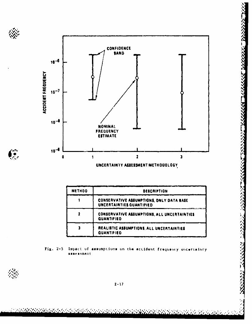
CONFIDENCE
%AN D
P1
10-a2
FREQUENCYTIQUrlMATI FI
0'
•,0 1 2 3 ,
UNCERTAINTY ASSESSMENT METHODOLOGY
METHOD DES|CRIPTION
1 CONIERVATIVE ASSIUMPTIONS, ONLY DATA SAIL[UNCERTAINTIES DUANTIFIED •
2 CONSERVATIVE ASSIUMPTIONS, ALL UNCERTAINT!IES,QUANTIFIED
p.3 REALISlTIC ASSUMPTIONS, ALL UNCIERTAINTIES S
QUANTIFIlED.€
Fig. 2-5 impact uf assumptlons on the acidotit frequency utscirtLetityMISC tlument .
.9. .* 0'l
Ua
.- .- "%.** *''' - , *. .. v'
No quantitative uncertainty analysis is performed for the agent
release calculations, due to the complexity involved in such an &*se*s-
cant. Instead, conservative releases are calculated.
I1
I t.- - '-
.. o. -,-. . 5. - , . o. .
2.7. REFERENCES
2-1. U.S. Nuclear Regulatory Commission, "PRA Procedures Guide," NUREG/
CR-2300, 1982.
2-2. GA Technologies Report for Sandia National Laboratories, "High-
Level Waste Preclosure Systems Safety Analysis Phase II Progress
Report," GA-C18557, August 1986.
2-3. Fleming, K. N., "A Reliability Model for Co n Mode Failures in
Redundant Safety Systems," Procedures of the Sixth Annual Pitts-
burgh Conference on Modeling and Simulation, April 1975.
2..4. Swain, A. D., and H. E. Outtmn, "Handbook of Human Reliability
Analysis with Emphasis on Nuclear Powter Plant Applications,"
SNUREG/CR-127., SAND 80-0200, August 1983.
2-5. Koch, P. and H. St. John, "STADIC-2, A Computer Program for
Combining Probability Distributions," GA Report GA-A16777,
July 1983.
2-19 •,
PI
E
3. CONTINUED STORAGE DESCRIPTION OVERVIEW
Chemical mnitions are currently stored at eight CONUS sites
(Fig. 1-1). A description of the CONUS sites, including local maps, is
given in Appendix D. Section 3.2 provides a summary description of the
nunitions. r
A detailed discussion of the long-term storage and handling oper-
ations associated with the continued storage option is presented in
Appendix G. Section 3.1 provides a sumary of these activities as they
relate to the rink study.
3. 1. CONTINUED STORAGE ACTIVITIES AND RISKSS.,%
The major activities for the continued storage option involve long-
term storage as well as handling activities associated with surveillance
and maintenance. They are discussed in the following paragraphs.p
3.1.1. Storage
During storage, the only planned activities are monitoring for
leakage, surveillance miantenanc, and repair i - nitions in the stock-
pile. Internal events for storage thus address leakage between inspec-
tions and munition drop or forklift tine puncture during munition han-
dling. The stored munitions are susceptible to external events, such as
fire, tornado, aircraft or meteorite crash, earthquake flood, and
lightning.
V3..
3-1
.................................................... ... ...
bp%
3 .1 .•2 .• Hand lfin g ,• . •
b
Basically, the risks associated with handling operations stem from .
accidents caused by equipment failures or human error. The types of b.4
accidents are: vehicle collisions, forklift tine punctures, and drops
of munitions. The =nitions affected may be single, in bare pallets, or
in a container. The locations of the agent release may be indoors, or
in the open (outdoors). Externally caused handling accidents were not
considered in this analysis because of the short time spans for actual
outdoor handling operations.
3.2. MUNITIONS DESCRIPTION
This section describes the munitions that comprise the CONUS muni- 1b
tions stockpile. The minitions stored at each site are summarized in
Fig. 1-1. As indicated the inventory of wanitions and bulk agent in
storage differs greatly from site to site. Detailed information on the
precise numbers of chemical agent munitions, at each site is classified
except for the information on M155 rockets. All of the chemical muni- -"
tions in storage are at least 18 yr old (production of new chemical .'*
munitions was stopped in 1968), and some are more than 40 yr old.
The munitions stockpile consists of 11 different munition types.
A detailed description of each munition type, including a discussion of
their thresholds, is presented in Appendix F. A brief description of
the munitions follows.
3.2.1. Rockets
The M55 rockets are filled with either GB or VX. The rockets are
equipped with fuzes and bursters which contain explosives. Propellant
is also built into the motor of the rocket. The rocket casing is made
of aluminum. Some of the rockets have a leakage problem.
3-2
The rockets are individually packaged in fiberglass shipping tubes
with metal end caps. Fifteen containers with rockets are packed on a
moded pallet.
3.2.2. Land Mines
Mines contain VX and explosive charges. The mines are packaged
three to a steel drum. Mine activators and fuzes are packaged sepa-
rately in the same drum. Twelve drums of mines are contained on a
wooden pallet.
3.2.3. Proiectiles and Mortars
The munitions stockpile contains 105-mi- projectiles with GB or mus-
tard, 155-mm projectiles with GB, VX, or mustard, 8-in. projectiles with
GB or VX, and 4.2-in. mortar projectiles with mastard. Some 105--u pro-
Jectiles are stored as complete rounds containing fuze, burster with I.
explosive, cartridge case and propellant, vthle others are stored with-
"out bursters, fuzes and propellant. Mortars are stored with fuzes, bur- 'V
sters, and propellants. Projectiles (155-rn and 8-in.) are also stored
with and without bursters. For this study, it was assumed that fuzes
and propellants have been removed from the 4.2-in. mortars and 105-mm r
cartridges.
The 105-mm projectilts *re packed 24-projectile; to a pallet, and
the 4.2-in. mortar projectiles are packed 48-projectiles to a pallet.
155-rn and 8-in. projectiles are packaged eight and six projectiles
on a wooden pallet, respectively.
3.2.4. Bombs
There are three types of bombs, all containing GB agent. These
are Lhe tIC-I, a 750-1b bomb, Lhe tX-94, a 500-lb bomb, anA thC K-.-11-
3-3
,%.
(*weteye"), a 525-lb bomb. The 525-lb bomb Is designed to release an
aerosol spray of agent on detonation. The bombs ore stored without
explosives. The MC-i bombs are packaged tw to a wooden pallet and the ,
others in individual metal shipping containers.
3.2.5. Spray Tanks
Spray tanks contain VX agent. They are designed for releasing
chemicnl agent from slow-traveling, low-flying aircraft. The spray
tanks are stored in a metal overpack container.
3.2.6. Bulk Agent 'IAll three types of agent are stored in bulk as liquid in standard
oue-ton steel containers (called ton containers). Ton containers are
not palletized.
Ton containers are the only items stored at the Aberdeen Proving
Ground (APG) and Newport Army Ammunition Plant (NAAP). The ton con-
tainers at APG contain mustard (HID), while NAAP has VX-filled ton con-
tainers. The Anniston Army Depot (ANAD) has filled ton containers.
Pine Bluff Arsenal (PBA) has mustard-filled ton containers. Tooele Army
Depot (TEAD) has all types of bulk agent in storage. Umatilla Depot
Activity (UMDA) has -mustard-filled ton containers. '--
*o*
3-4"
. .
, , . . , - . -. .. .. - , .. • .... , .. " . " , . ..... . ,:" . • . : ,, - •, : .. ,- " • .," ",,,'• ",I• •'.• ,'• ' .
,-j
4. INITIATING EVENTS
This section describes the aproaches used to identify and selezt
iritiating events and to asaess or present their occurren-e frequencies
As described in Section 2, Init-ating events are single occurrences or
individual malfunctions that either directly cause the release of chemi-
cal agents or start a sequence of events itiat could lead to a release.
They are classified as *,ternal even~ts vhen caured by natural ptLenomena
(e.g., earthquakes) or man-made interferences (e.g., ai.rcraft crashes)
from oitside the demilitarization cycle. They are clacsified as inter-
nal events when cat saed by haman error or equipment failure within the
demilitarization process. Section 4.1 describes the lcgic used for
selection of the initiating events. Section 4.2 discusses the geueric
.- o•side~at± 1c. specifyng the initi&ting event frequency units (i.x.,
per unit time or per operation). The application of the generic fre-
quency estimates to specific accident scenarios and locations is dis-
cussed in the sections dealing with accident logic model development,
Sections 5 through 8.
4.1. INITIATING EVENT IDENTIFICATION AND SELECTION
This study used a multifaceted approach for identifying potential
B initiating events, screening out those which (based on conservi.tive
scoping) should not affect the overall risk and selecting those *vents
warranting further analysis. The approach consisted of:
0 1. Developing a master logic diagram (MLD), a logic tool described
in the PRA Procedures Guide (Ref. 4-1) for systematicalli
examining potential modes of release, pathways for reloige.
barriers against release, and mitigating safety functions
together with roo.- can (initiators) of release.
4-1_X'
a. , . .•
2. Cross-referencing results from item 1 with a list of accident
scenarios from safety-related studiec on the cbemical weapons
disposal program, compiled by MITRE Corporation in Refs. 4-2
and 4-3.
3.. Applying previous munitions risk study experience in Refs. 4-4
through 4-12 (the results of these studies are described
in S.ction 1.1).
4. Peer review by the Army and independent consultants during the
early and draft report phases of this study.
Two criteria were used to screen accident scenarios: (1) accidents
with extremely low frequency (below 10-10 per year) were eliminated from
further analysis, and (2) those with low consequences (amount of agent
release below 0.3 lb for GB, 14 lb for H or 0.4 lb for VX) were also
screened. Events with frequencies below the cutoff bave little meaning
froi a p& tal standpoint a&inc the expected times betwesn events is
measured on a cosmic scale :ather than on a scale of human history. The
consequence criteria pertains to the minimum release levels that would
produce acute human fatalities 0.5 km from the incident, based on envi-
ronmental impact calculations performed by MITRE (Refs. 4-2 and 4-3).
For bookkeeping purposes, a coding system is used in this report
to identify, organizc and refer to accident sequences. Not all accident
seq.iences were encoded; those that could be screened out early because
of simple conservative scoping analysis bear no coding. Conversely,
many sequences that were screened after detailed analysis retain their
coding but may not be in the final lists of results. However,
Appendix A contairis a record of all encoded sequences.
Table 4-1 shows the coding scheme followed for identification
of accident sequences. The coding system is based on that used ir,
4-2
V.t % w
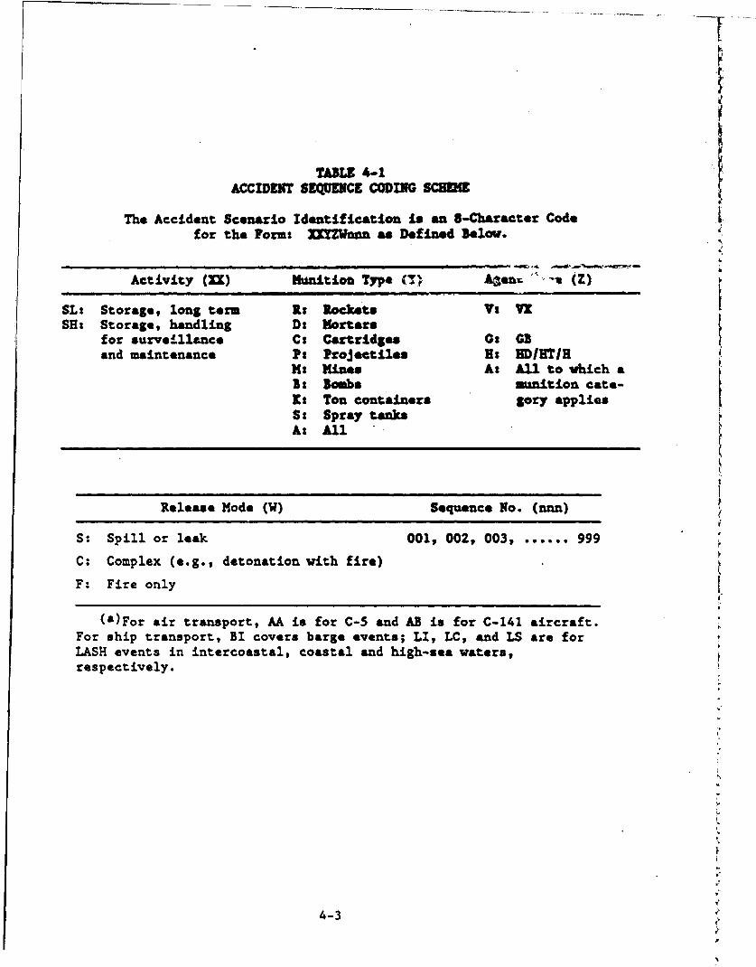
TABLE 4-1ACCIDENT SEquENCE CODING SC~MW
The Accident Scenario Identification is an 8-Character Code -for the Form: MMZhan as Defined Below.
Activity (M ) Mnnitio u Type ) aeur V. (Z)
SL: Storage, long term K: lockets Vt VXSH: Storage, handling D: Mortars
for Surveillance C: Cartridges G0 GBand maintenance Pt ProJectiles R: RDIHIH
M: Mines A: All to which aB: Bombs munition cate-Ks Ton containers gory appliesS: Spray tanksA: All
Release Mode (W) Sequence No. (nnn)
S: Spill or leak 001, 002, 003, ...... 999
C: Complex (e.g., detonation with fire)
F: Fire only
(a)For air transport, AA is for C-5 and AB is for C-141 aircraft.For ship transport, BI covers barge events; LI, LC, and LS are forLASH events in intercoastal, coastal and high-sea waters,respectively.
44-3 '
Refs. 4-2 and 4-3. The first two letters Identify the demilitarization
phase (SL for storage, long term, SN for special ubdlLia a•£ivities).
The first two letters together with the sequence number at the end
uniquely identify an accident sequence of events. The middle letters
Identify the munition/asgent type combinations and the release mode.
Throughout this report, either the entire coding is used or sequences
are referred to by the first two letters and the sequence number.
The MMD developed for the risk study event identification is
shown in Figs. 4-1 through 4-3. Following the PRA Procedures Guide
(Ref. 4-1), the top level logic (Fig. 4-1, level 1) pertains to the
public impact, in this case, fatalities due to exposure to chemical
releases throughout the long-term storage.
Figure 4-2 shows lLD level 2 (release mode or pathway) and subse-
quent levels (barriers to release, safety functions mitigation/failure
and, finally, event initiators) for storage. It shows three modes for
release. One is leakage of agent from corroded munitions, such as
leakage of a ton container stored in open areas. Another is inadvertent
rupture of a munition during maintenance. The third is a disruptive
influonce due to an external event.
Subsequent levels are developed considering the types of disruptive
events that can occur, taking into account information on the potential
failure modes of the munitions (puncture, detonation, fire, etc.), given
that the event occurs. For illustration, some sequences analyzed in
Section 5 are noted under the initiating event boxes. Table 4-2 sunma-
rizes the initiating event families for storage selected for analysis.
Figure 4-3 shows the MLD levels 2 and lower for handling opera-
tions. There are modes of release: impact rupture due to handling
accidents (drops and forklift collisions), and forklift tine puncture.
Note that external events are not included here; external events for
storage and transport consider the entire munitions inventory available
4-4
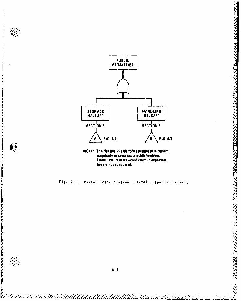
0,.
LPUBLILFA.TALITIESI I
• .oU,.. NOTE: magnitud nlyto ca ntvf, Public ofatal i nties.
but are not conudered.
Fig. 4-1. Maeter logic diagramr level 1 (public impact)
A
A
4.-5
A"I
. . -' ? . . .... ' ~ f *.,, .. . . . .. .. 1 _ k _. _, -, ,,.. ,,~ - -. § , , . .> . . . , , . . . ... .J . . o A h
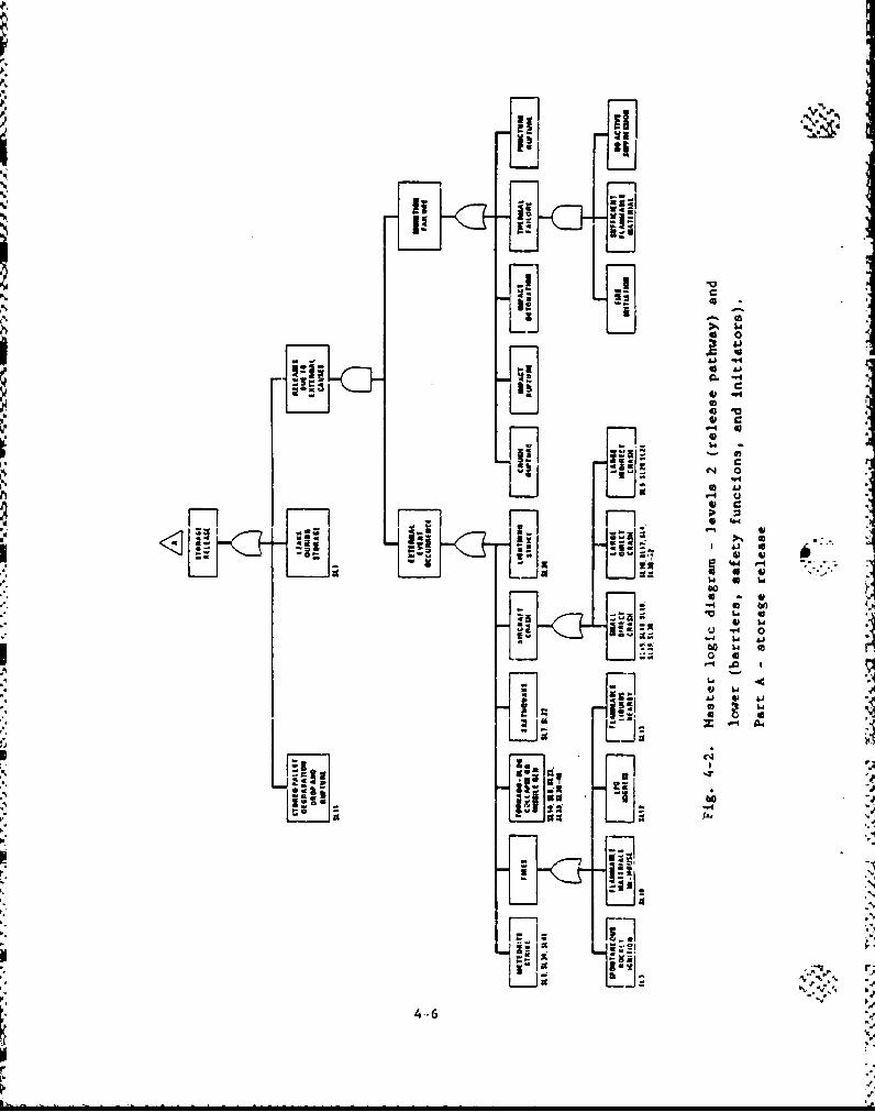
Iwo
I!
~CO
0!
N I
a lix II
4.-6
Tx- 60 w
;z; 0 4
"4 w
4-6
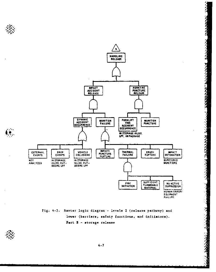
I.ILI
HAN OLIN GRELEASE
EXTERAL DRP VEIC IPACT/ ThERMA TCINEPA
ACCIVENT PIUNCTURERELEASE RULRAEE
FAIUR PUNACTURE
OC 1 FR 1E ACIOENT "
I,&IALAURONI "naAL
OOUR[RR PRROR'
lo, bareasft fwAcCiOna !~~. .ntits)
0 •'TORA6E IGLOO,PartI- ,aFl. in PACKAGErl
Ir
EVENTS E VENTS COLLISIONS n UNCTU ;E FAILURE L RUPTURE Ei NAT0f
NOT IN STORAGFE iNST'oRAt;E | URST;ERED0'ANAILYZE IGLOO, OuT- IGLOC, 0UT-• MUNITIONS,
C)OOPS, I.FF DOORS. LPF r
=9X~njt ON LtS A JA
HUVANl ERRR0/
Fig. 4,-3. haster logi.c diagra levelsI 2 (ralease path-wroy) and.-,
lower (barriers, safet:y £fnctiom, omd iIti£ators). o
Pat'1 B - storag;e reolease -
4-7
S.. . . . . . . . . .. .... .. . . ... .... ... .. .
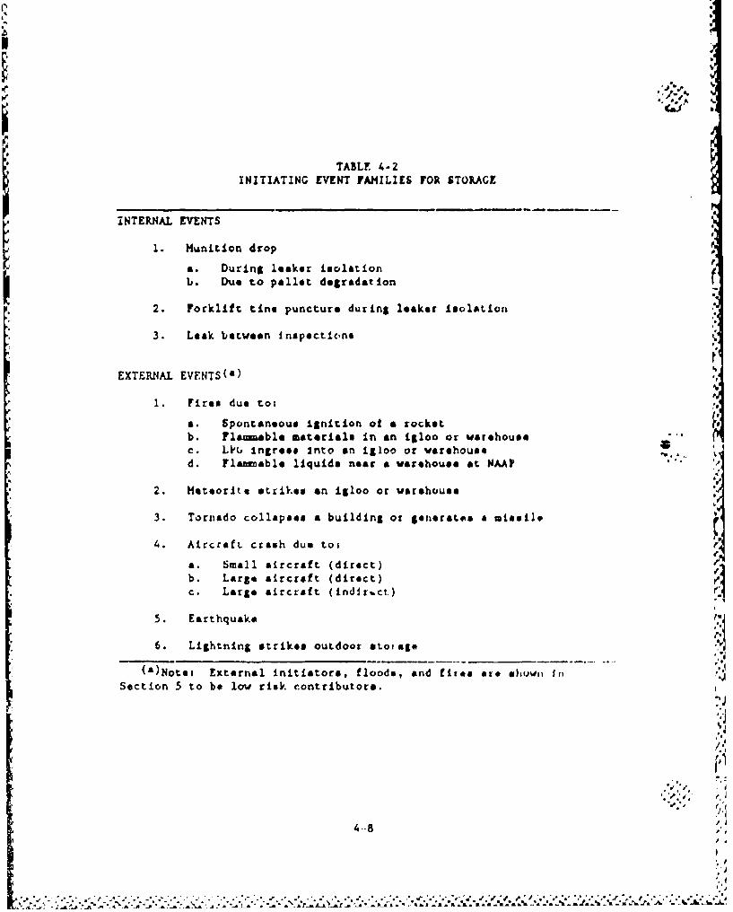
I€V
TABLE 4-2INITIATING EVENT FAMILIES FOR STORAGE
!NTERNAL EVENTS
1. Munition drop
a. During leoker isolationb. Due to pallet degradation
2. Forklift tine puncture during leaker lsolAtion
3. Leak between inspections
EXTERNAL EVFNTS(a)
1. Fire* due to:
a. Spontaneous ignition ot a rocketb. Flamble materials in an igloo or warehousee. L' I ngress Into en igloo or warehoused. Fla-able liquids near a varehouse at WAAP""
2. Meteorite strikes an igloo or warehouse
3. Tornado collapses a building or generates a missile
4. Aircraft crash due tot
a. Small aircraft (direct)b. Large aircraft (direct)c. Large aircraft (indlr.ct.)
5. Earthquake
6. Lightning strikes outdoor etoiag.e
(a)Note, External initiators, floods, and fiU ra *te ehrtwii In
Section 5 to be low risk contributors.
4.-8 %/ -4/
S* ,'d
regrdlev of vh.thor hancling operartione are in progreos. The sub-
sequoet level Initiating events consider the location where the event
occur., eince different barriers for release are invol.vcd (e.g., if the
event o(.r'ur, indocor'j or In an opon areo). Fseontially, there are 18
(3 x 3 x 2 matrix) hatdling ,.cident combinations. Theee are related
to the nu•,ber of U•h,,t.Itvtn% involved (a single, mtoition, pallet, or con-
tair.er)l the releas- sichaniea (dro'?, forklift collision, or forklift
tino porircuieog ad whetaher the release occurs Inlsde or outdoors.
74,1. 4-3 auueirlteo th. fawflies ot haridlt I£niLtiatintg events selected
for analysl.
lb
I.
P
.. %
di V
3 F"€ .* -• '* •, € ,, €_ " ' ''".. . . • _ ".3 _ . . . . . ... ..-- ,. - . .. 3.'. . • . ...
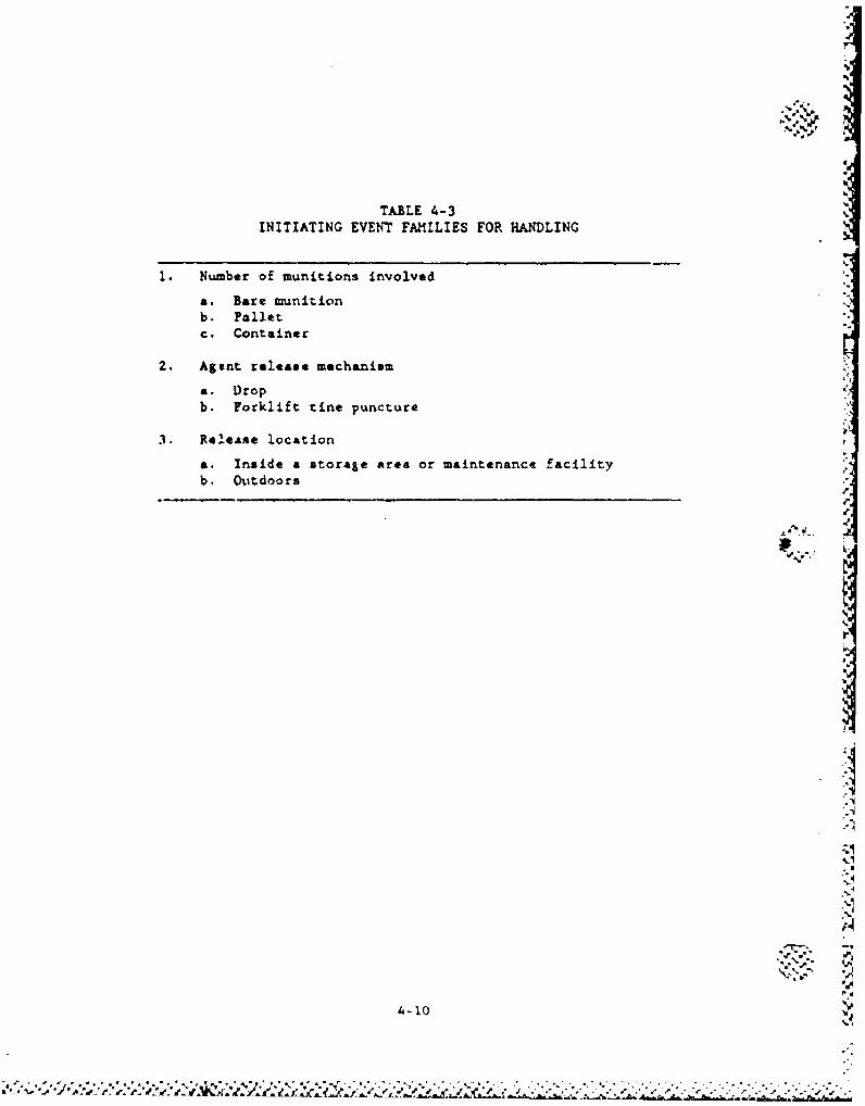
%-
TABLE 4-3INITIATING EVENT FAMILIES FOR HANDLING
I. Number of munitions involved
a. Bare munitionb. Palletc. Container
2. Agent release mechanism
a. Dropb. Forklift tine puncture
3. Release location
a. Inside a storage area or maintenance facilityb. (hOtdoors
4-10
I-I
V.
4.2. INITIATING EVENT FREQUENCIES
4.2.1. External Events Ie
This section presents the site-specific frequencies of external
initiating events considered in this study. Table 4-4 summarizes the
results for occurrences at each of the eight CONUS sites. The bases for
these results are discussed in the following subsections."I-
4.2.1.1. Earthquakes. The frequency at which a major earthquake occurs
at a specific site varies significantly throughout the United States.
In an attempt to quantify the seismic risk associated with A paiticular
site, the Seismology Committee of the Structural Engineers Association
of California (SEAOC) has divided the United States into five seismic
zones. Maps of these seismic zones are presented in the Uniform Build-
ing Code (Ref. 4-13) and in Army TM 5-809-10 (Ref. 4-14). Figure 4-4
presents the seismic zone map from TH 5-809-10, and Table 4-5 presents
. the seismic zones indicated for each of the storage sites. The proba-
bility of seismic damage in each of the zones is defined in Ref. 4-13 as
follows:
Zone 0 - None Zone 3 - Major
Zone 1 - Minor Zone 4 - Great
Zone 2 - Moderate
The determination of a seismic zone on a site is based on the his-
tory of past earthquakes and the proximity of known faults. Appendix D
presents listings of the earthquakes that have occurred in the vicinity
of each of the storage sites. The magnitudes of the earthquakes are
expressed as Modified Mercalli Intensities (MMI). Table 4-5 presents a
summary of the maximum earthquake occarring in the vicinity of each of
the storage sites. The maximum earthquake recorded at any of the eight
storage sites is an MMI VIII.
4-11
hq
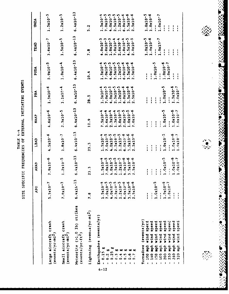
V) uU Zininin0%a %O0 w 1%0 a'ý
1 1C 0 0,- 0000000 00 10CI
N ~~~ N N N N N Nw N w>
In r- -0 I00 N ~ 0060 6o fn~, IN-4'4..1 1
9-I 9- kn -I - -0 I -4.- In- %n ba a O
!- 110 IQ 1 . -
10 -1 0- 0 01 004 00.04M -4ý
In I m D r 4P 4.4I - .
I I I I I6 I I S I I I0l 0 0 0000 000 0 00 I
9-4 4 v-4 "949If4 P-4 M Mm 4 r4.
N 4 INN -I %GO N N I IW 41
0% 0 .6 0%01 0V1016 Vl 6 60 00 6
P4 1 9.4 ,-4 -4.I f % m a-I 6,ý ý-46 I- 6.
In In 0 0 In IN &A I 1 6 C3 6 ýC
Inin . *4 V.60-C . 0 w UIaIaW. $0 In o r
1-4~~~1 10 110 10 4'% DV10 ea 1t
4: f- --I *-4 ý4 -4- -4 -
4: 4 0I " %A In et ' voOO 6666 '00%
Z~- 6 o'.. .. . . . CD 6 0.4 1. C10 .- '.9 .4 V-4 14 6 6 6 1,-I r.-4~
f%.0 N -4N .. V % 1 1 ) 14 1r 0 0 v-4 9.IeN
E-cj -d 4 10 ,.4 -4 . 0~ A -4 .4 -4 4,I
Cl In In in %A %Q w % I6
0 ctl 0 0 0000000 0 00 I
Cl..40e oa 0 0 0 0
La) ~ ~ A I: N AiN NN NNN N
1" -4
DIN
5-4 C4 -. 4C4r nýrk 0r ~In) -4 V-n w o%a0 1- -4 N
- - -0 - - - - - - - -- - J -- E- - - -i~
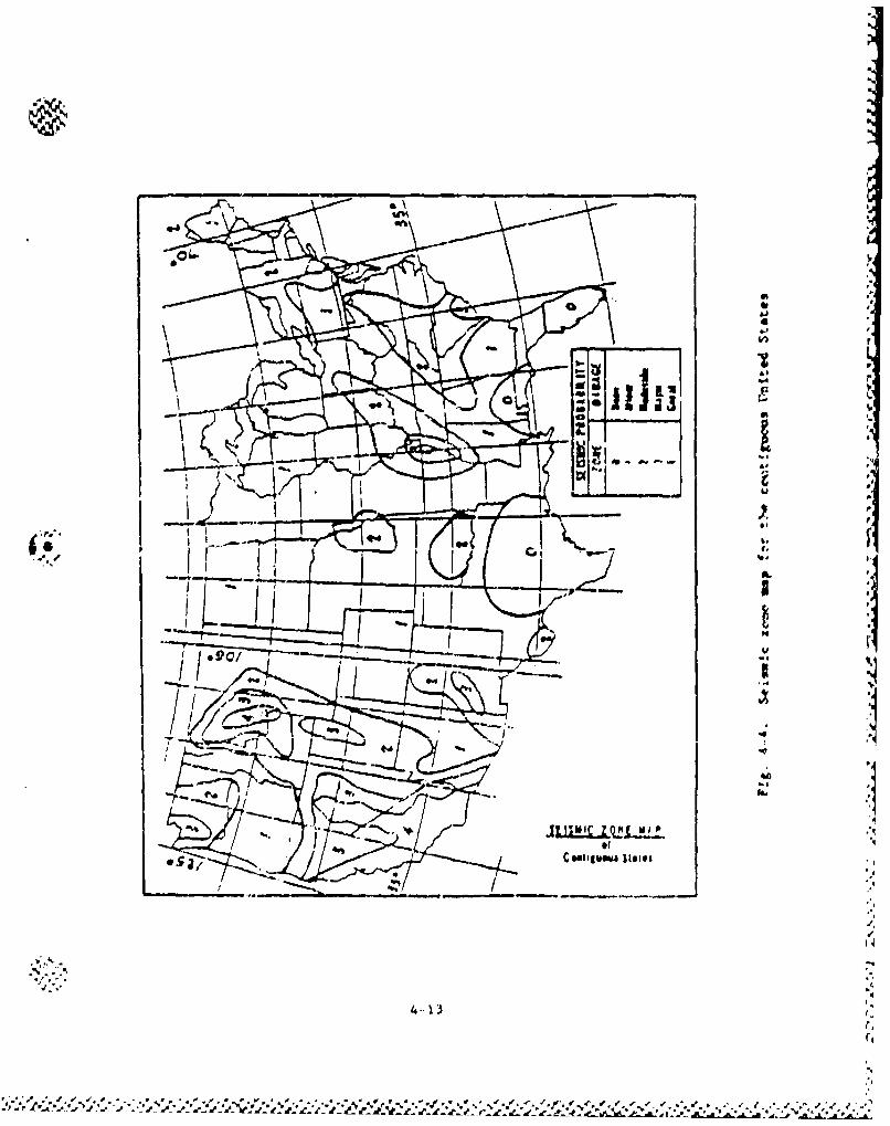
* 4.&�56
�4)
�eUIU� -4
C �flJjJ
IU
7*4
b.(4
-. 4 - Ii/ I��/�*E�z./ I /�-•gz��--
T � (.1
�-..4 'C
-, -,
of -q
Ceu"gwuw. �.i.n .
A
-- 4. .�' I-4,.4
'4
4% -4
4/p --4.
4-13�4
44
(I
.4
.4
� V .4.4.4 .4 .�' � 4*.* 1 '
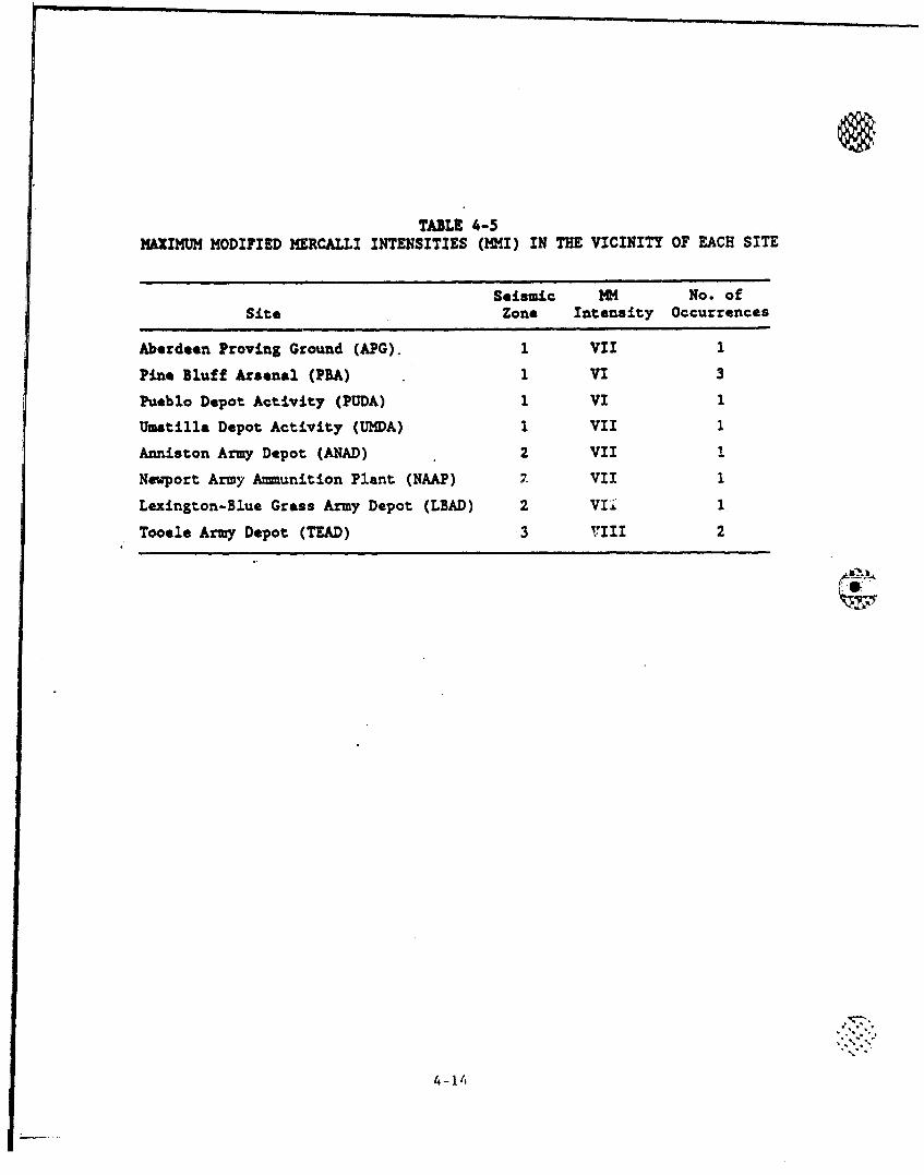
TABLE 4-5MAXIMUM MODIFIED MERCALLI INTENSITIES (MMI) IN THE VICINITY OF EACH SITE
Seismic M No. ofSite Zone Intensity Occurrences
Aberdeen Proving Ground (APG). 1 VII 1
Pine Bluff Arsenal (PBA) 1 VI 3
Pueblo Depot Activity (PUDA) 1 VI 1
Umatilla Depot Activity (UMDA) I VII 1
Anniston Army Depot (ANAD) 2 VII I
Newport Army Ammunition Plant (NAAP) 2. VII 1
Lexington-Blue Grass Army Depot (LBAD) 2 Vii 1
Tooele Army Depot (TEAD) 3 VIII 2
4-14
Currently the Applied Technology Council, which is associated t
with the SEAOC, is developing new seismic regulations for buildings
(Ref. 4-15). When this work is completed, It is expected to be the
basis for future federal, state, and local building codes. Part of this
work was the development of a seismic risk map that divides the United
States into seven seismic map areas similar to the five seismic zones
used in Refs. 4-13 and 4-14. The seismic risk is approximately constant
throughout a seismic map area.
Figure 4-5 (from Ref. 4-15) presents a set of curves that can be
used to estimate the probabilities of earthquakes of various g-levels
occurring within a particular seismic map area. The dashed portions of
the curves indicate possible extrapolations to larger and smaller annual
probabilities.
Table 4-6 identifies the seismic map areas for each of the CONUS
sites and tabulates the annual frequencies of earthquakes of various
g-levels being exceeded at the storage sites. The data in Table 4-6
were obtained from Fig. 4-5. Straight-lin., logarithmic extrapolation
was uded to extrapolate to accelerations beyond the curves sho.m in
Fig. 4-5. This method of extrapolation is believed to produce conserva-
tive estimates of the probabilities.
4.2.1.2. Wind Hazards. Methods for estimating the frequency and inten-
sity of extreme winds can be found in ANSIIANS-2.3-1983 (Ref. 4-16).
The discussion whicýi follows is largely based on the referenced nationel
standard,.
4.2.1.2.1. Tornadoes. A tornado is a violently rotating column of
air whose circulation reaches th6 ground. The velocity of tornadic
winds can exceed 300 mph. The path of a tornado can be more than a mile
in width, buz generally ranges from 0.125 to 0.75-mile wide. The path
wIA-h Is defined as the tornado diameter corresponding to a 75 mph wind
"��~ •c. The path of a tornado is seldom more than 10 mile! long,
4-15
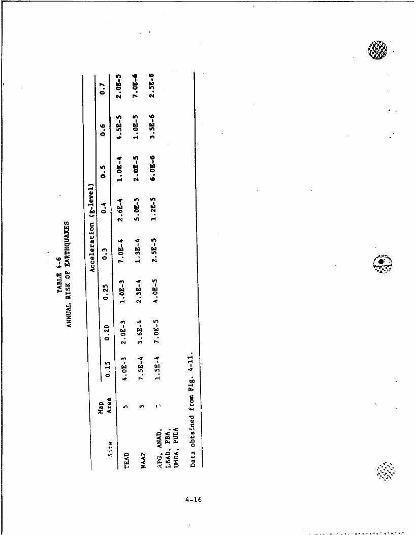
0**en '0 '0
* I Ci� hi hi hio 0 eno * *
N *b. N
en en '0
* S I
'0 hi hi hien o en0 * *4 1-4 en
� en '0
I I I
en hi hi* 0 0 00 * *
i-I N eo'-IS
* en enb� *:. h�
�0 '0- . . .
N Ifl i-C
� en0' I I I
gi en hi hi hi14 * c en en
S 0 r-. i-4 N
hib
��t0 en � enen I S
N hi hi hi0* o en a
r4 N 4�N en I�-
en 4 4 -4en I S C 9�4r4 hi hi hi
* e en en 40
4 ,�. -4-4
a0.4I* w en v' t�
4.4'a@3
-- ' -4
@3 Z�4�4 *�0
aJJ
I- -. �--
4-16
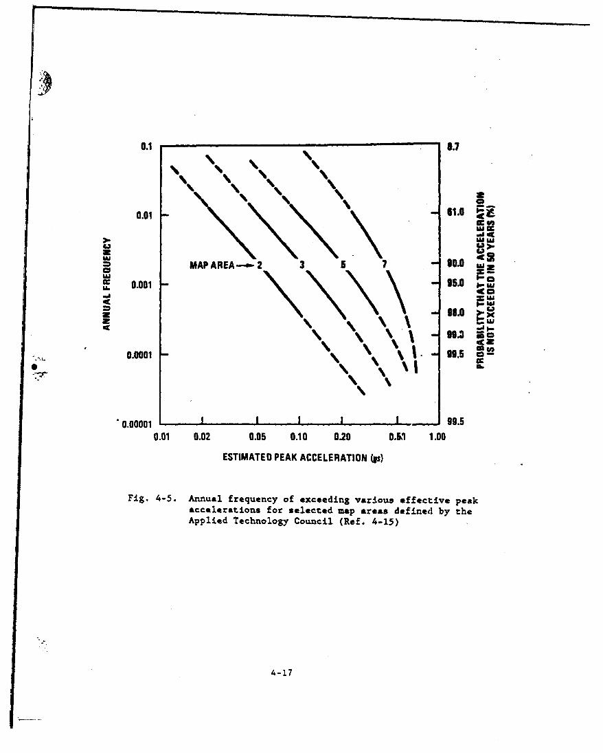
0.1 0.7
0.01 61.0
)..~&WWsWE
MAP AREA-.- 2 - 90.0
c 0.001 95.0
Uj
0.0001 v\. % 5* \7\9.
"0.00001 - 99.50.01 0.02 0.05 0.10 0.20 0.5 1.00
ESTIMATED PEAK ACCELERATION (Is)
Fig. 4-5. Annual frequency of exceeding various effective peakaccelerations for selected map areas defined by theApplied Technology Council (Ref. 4-15)
4-17
although extreme cases are on record where the storm path extended more
than 200 miles.
Meteorological and topographic conditions, which vary significantly
from site to site, influence the frequency of occurrence and intensity
of tornadoes. Reference 4-16 presents three regionalized maps of tor-
nadic wind speeds corresponding to return frequencies of 1 x 10"7, 1 x
10-6, and 1 x 10"5 per year. These maps (Figs. 4-6 through 4-8) are
expected to bound the tornado intensity probabilities at the various
sites (Ref. 4-16). A tabulation of maxum tornado wind speed and
occurrence frequency for each of the storage sites based on these
figures is presented in Table 4-7.
4.2.1.2.2. Tornado-Generated Missiles. One of the characteristics of atornado is its capability to generate missiles from objects lying within
the strike area and from nearby structural debris. The selection of
tornado-generated missiles is dependent on the intensity of the tornado,
the number of potential missiles present, their position relative to the
tornado path, and the physical properties of the missiles. Reference
4-17 presents a spectrum of actual wind-generated missiles. Character-
istics of these missiles are listed in Table 4-8, and expected windborne
missile velocities are listed in Table 4-9.
4.2.1.2.3. Other Extreme Winds. The approach used for the determina-
tion of extreme wind speed (other than tornado) including hurricane
winds is the method suggested by Science Applications International
Corporation (SAIC) (Ref. 4-12) using a basic wind speed as defined in
Ref. 4-16. A frequency of occurrence of 0.02 per year is associated
with a basic wind speed of 70 mph. SAIC concluded that the basic wind
speed was applicable to all of the sites that store M55 rockets. Lack-
ing site-specific meteorological data, it is assumed that the basic wind
speed is applicable to the other sites as well.
In order to estimate the frequency of recurrence of winds of veloc-ity greater than the basic wind speed, but less than the tornado wind
4-18
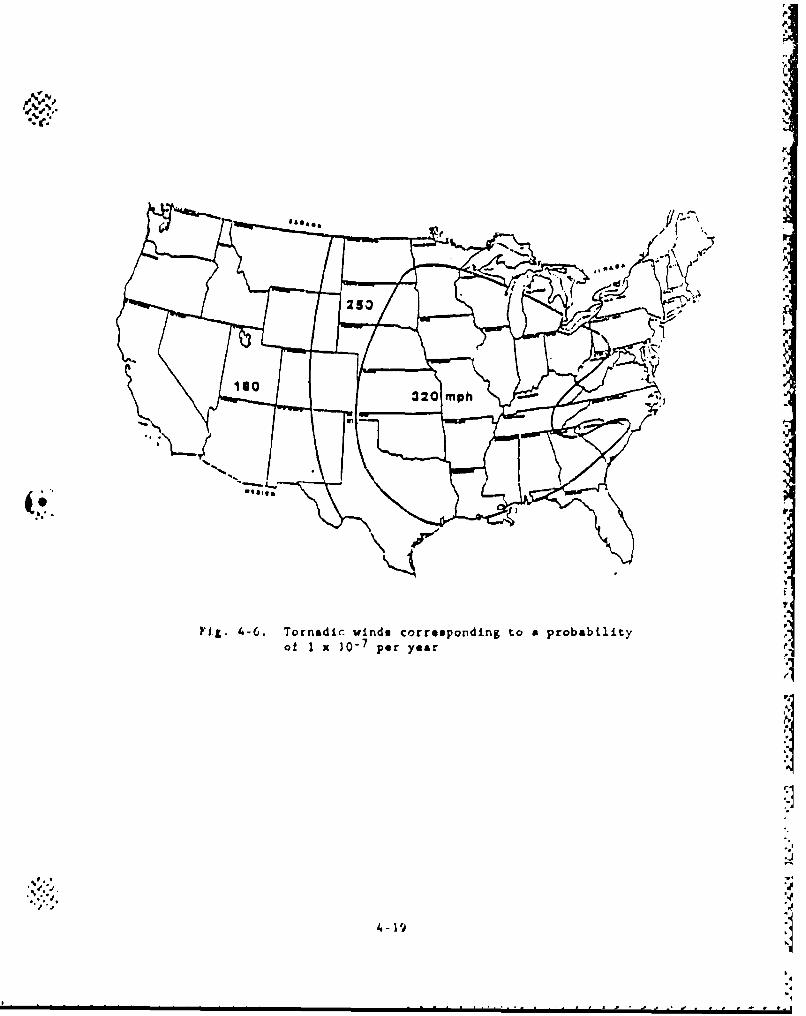
1"p
Fig. 4-6. Tornadir winds corresponding to a probabilityof I x 30"7 prya
4-19*
°p
• '• .'.' ,-
Fi.46 Trai -ind corupnin-o. roailt
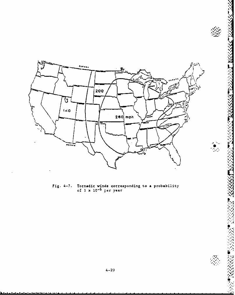
Fig. 4-7. Tornadic winds corresponding to a probabilityof I x• 10-6 ier year
4-20
. . .. .... .
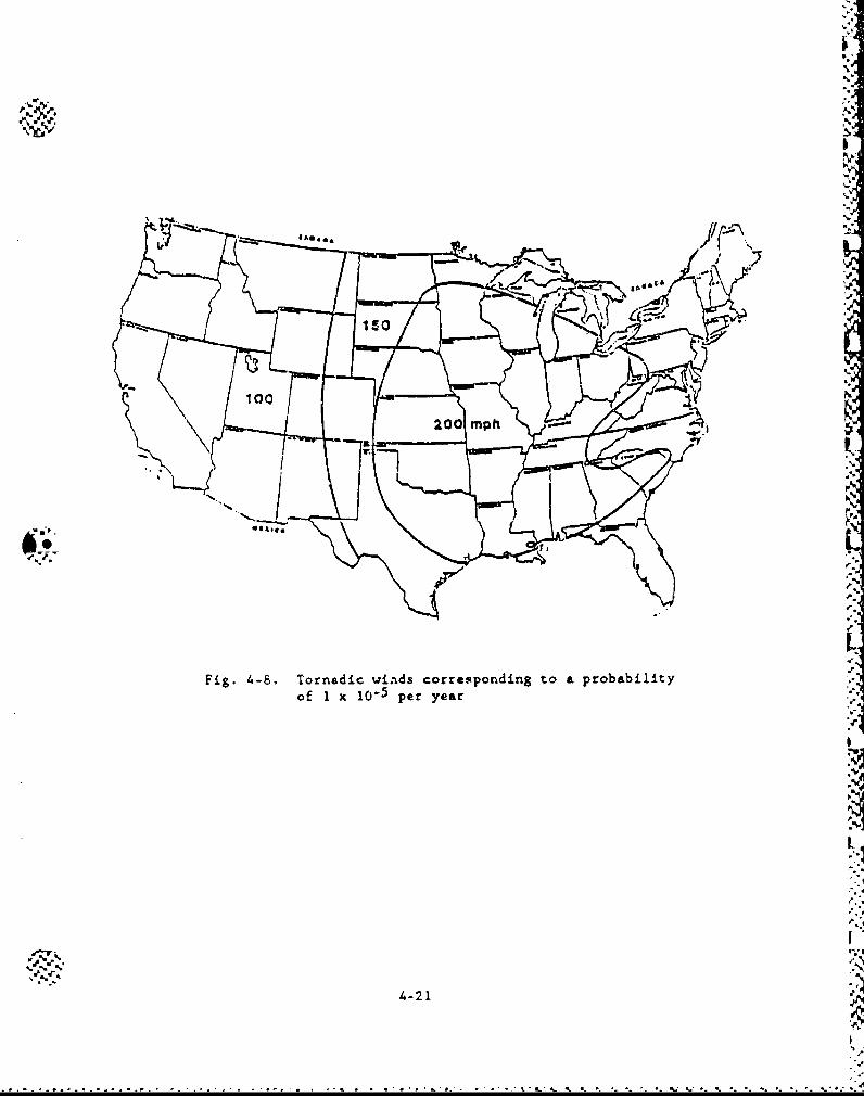
"Cb"
15A.
4-21
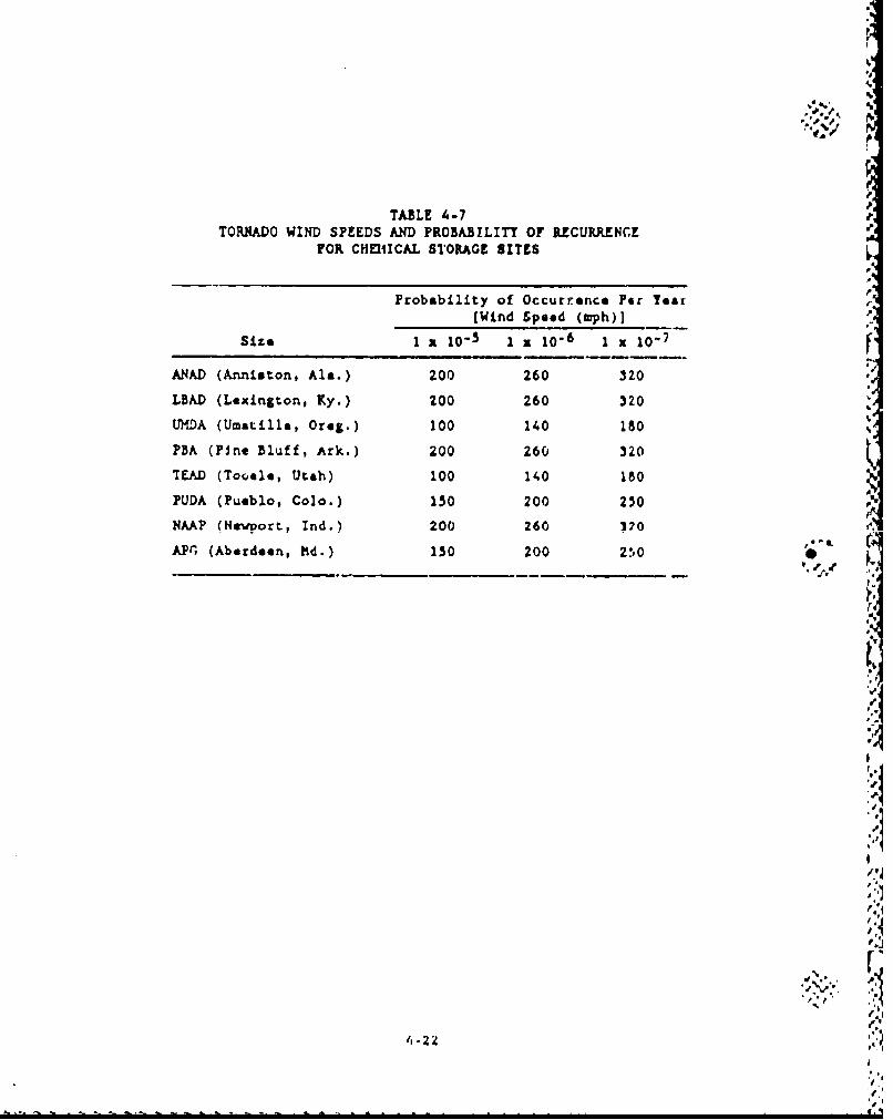
TABLE 4-7
TORNADO WIND SPEEDS AND PROBABILITY OF RCURRENCEFOR CHEMICAL STORAGE SITES
Probability of Occurrence Per Year(Wind Speed (mph))
Size 1 x 10⁵ 1 X 10⁻⁶ 1 X 10⁻⁷
ANAD (Anniston, Ala.) 200 260 320
LBAD (Lexington, Ky.) 200 260 320UHDA (Umatilla, Oreg.) 100 140 180
PBA (Pine Bluff, Ark.) 200 260 320
TEAD (Tooele, Utah) 100 140 180
PUDA (Pueblo, Colo.) 150 200 250
NAAP (Newport, Ind.) 200 260 170
APM, (Aberdeen, t'd.) 150 200 250
4%
j0t1
t,-
I.'
•%• !
4 -2Z,,.,
I
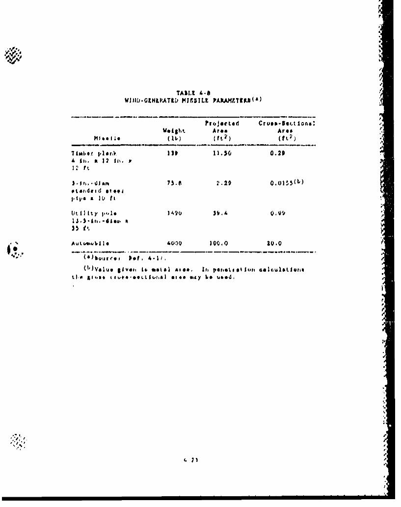
TASIt A-11/WIID.GNLA~ti *USILL PARMIEZfFJ(
Wegt Area Area
Tbob~t p1.ri, 130 11.10, 0.29
is III,
PtLIdoid dep ap x U ft
A utoh.'I.1* 4010 jQ00.0 20.0
tho go tui *iV tvt me*Ld Ita.&I oil pomeool lGekuLaLU60i
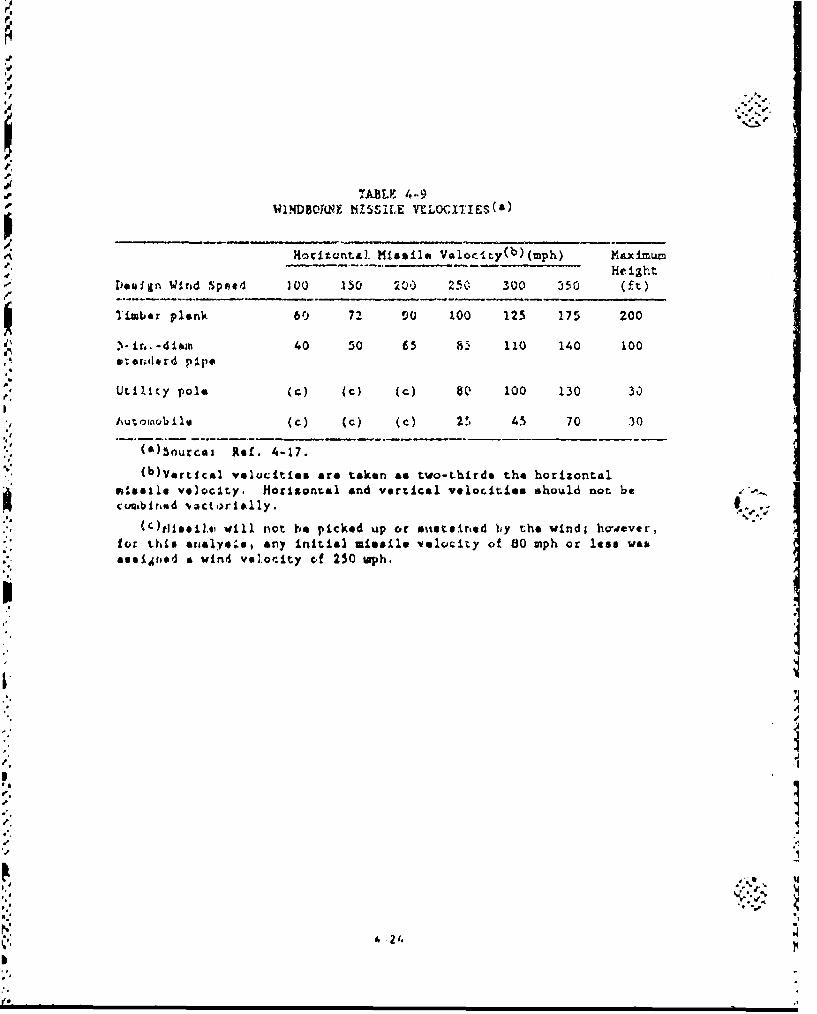
7ABLE. 4-9WINDBOANE HISSIILE VILOC.ITIFS(s)
Horitonttal. Missile Valoc',ty(b)(mph) Maximum
Doeal~n Wind .Speed 100 M• 20.) 2r-C 300 3C0 (t
Tiwba r plank 60 72 90 too 125 175 200
.- n.-i 40 50 fi5 8.• 110 140 100st at•,drd pi.ps
utility pole (c) (c) (C) 80 100 130 30
.'u• ~o i1J(c) (c) (C) 2., 45 70 30
(O)Sourcai Ref. 4-17.
(b)Vartical velocities are taken as t~wo-thirds t~he horizontal
m~issile ve)oclty. Mocitontal end vertical velocities should not be -•.cumbiriod 'vactoorloklly. ...
(0,ti11],,13 ill not he picked up ot stietair, ed ),y the windl however, ""
for this nl4w any Initial missile velocity of 80 mph or less wasssaeidtaod at wind vel.oci.ty of 250 wph.
.10
4
is -. ,
I !
speed, the following approach was taken. The tornado strength and fre-
quency data, and the basic wind strength and frequency data were plotted
on a scale of log probability versus wind strength. The results are
shown in Figs. 4-9 through 4-11 for the three tornado regions of the
United States as given in Ref. 4-16. A conservative approach to inter-
polating between the available data points is the bilinear approximation
shown by the solid lines in the figures. With these figures, the proba- '
bility of a given wind velo•!ty occutring at any of the chemical storage *-.
sites can be estimated.
4.2.1.3. Aircraft Operations. Much of the data in this section were
taken from the SAIC report (Ref. 4-12) and NUREG-0800 (Ref. 4-18).
There are three major concerns in assessing potential hazards due 1.,,
to aircraft operat-*ons:
1. Proximty ef aircraft operations to m.itions areas- '
Z. The frequency of aircraft flights.
3. The charactse:'stics of the aircraft traffic.
The proximity of aircraft operations to munitions activ2.ties is an
important consideration in that approximately 50% of aircraft accidents 14that result in iatalitief, or destroy aircraft occur within 5 miles of
airports (Ref. 4-12). Also, the close proximity of flight paths to
munition- activities in' reases tte likelihood of these areas receiving
falling debris :tcm sirzraft accidents. The frequency of flight activ- 5
ity increases the pose 4bility of damage to mumitions by increasing the
ovtralI± 'kelihood of an aircraft accident.
4- 2 5'
A..
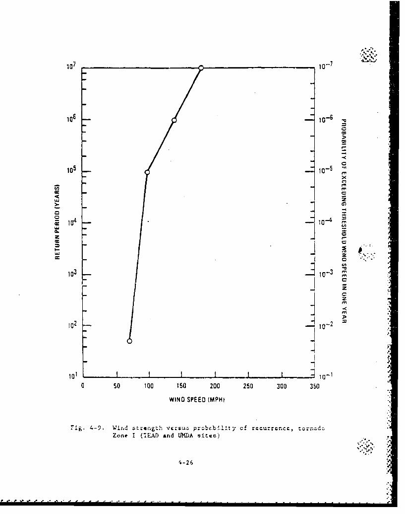
107 10-7
106 10-6
105 1 -
X
ICCI-M
-c IG l-1- 101a- =
C,n
-J z
CC -
103 10 -3
1--4
1 ,. 2
(0 so 10O0 150 200 250 300 350
WIND SPEED (MPH).•
Zone I (lEAD anrd UHDA rjite,=)
-~ io-i . ,i,
",-26 Va--
I I II ia-
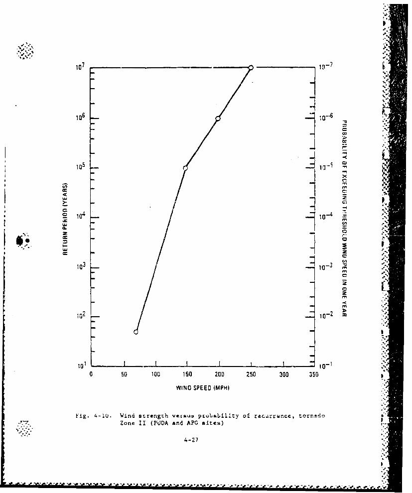
='a
107 ,10 -7
106 1O-6.
105 10-%
X
cc-4i
102 i0-
u.j
101 _.10-1 ,
0 ,50 100 ISO 200 7.50 300 350
WIND SPEEO (MPH)-'
•-a.
Fig. 4-1U. Wind errength vecsu•, pcobabillty" of recurrun-cc, torneado "
:-/ Zone II (PUDA and A.PG sites)
4-27 "2
"" %%
0 50 00 15 200 250 30,35
WINO PEED(MPH
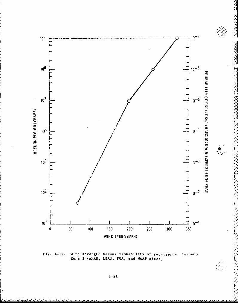
"07 -0-7-
10]6 10-6 "
H =_
-- e• _
10':
-0 -
-2aO 10-1
o 0 --III -4 o -•
oso 100o 15 200 250 300 350
WIND SPEED (MPH)
Fig. 4-11. Wind strengLh versus -)robability of rec,'rrejce, tornadoz-one I (ARAD, LBA0, PGA, acid NAA sites)
4-,2
"C .
F- ~~.,i." .
2-28~,j,* I I~fl In ic, In Ifll IC
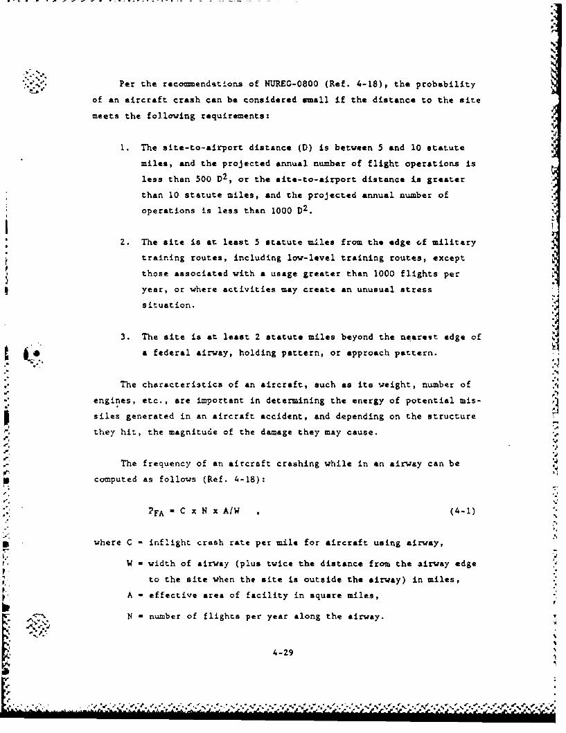
p." .- Per the recomnendations of NUREG-0800 (Ref. 4-18), the probability
of an aircraft crash can be considered small if the distance to the site
meets the following requirements:
1. The site-to-airport distance (D) is between 5 and 10 statute
miles, and the projected annual number of flight operations is
less than 500 D2 , or the site-to-airport distance is greater
than 10 statute miles, and the projected annual number of
operations is less than 1000 D2 .
2. The site is at least 5 statute miles from the edge cf military
training routes, including low-level training routes, except
those associated with a usage greater than 1000 flights per
year, or where activities may create an unusual stress
situation.
3. The site is at least 2 statute miles beyond the nearest edge of
a federal airway, holding pattern, or approach pattern.
The characteristics of an aircraft, such as its weight, number of
engines, etc., are important in determining the energy of potential mis-
siles generated in an aircraft accident, and depending on the structure
they hit, the magnitude of the damage they may cause.
The frequency of an aircraft crashing while in an airway can be
computed as follows (Ref. 4-18):
PFA C x N x AW , (4-1)
where C - inflight crash rate per mile for aircraft using airway,
W - width of airway (plus twice the distance from the airway edge
to the site when the site is outside the airway) in miles,
A - effective area of facility in square miles,
N - number of flights per year along the airway.
%-
4-29
. . .. . -. -�- . .. %- _ . % %P -M .
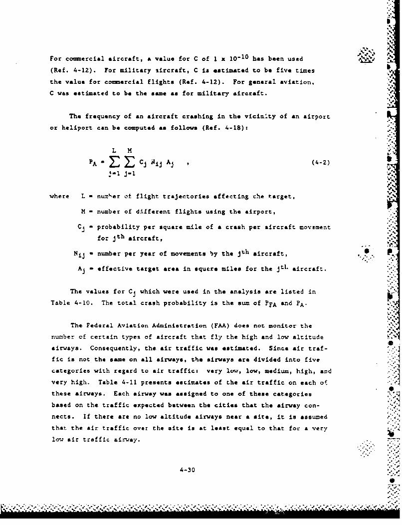
I
For comnmercial aircraft, a value for C of 1 x 10⁻¹⁰ has been used • '
(Ref. 4-12). For military tircraft, C is estimated to be five times
the value for commercial flights (Ref. 4-12). For general aviation.
C was estimated to be the same as for military aircraft.
The frequency of an aircraft crashing in the vicin.ty of an airport
or heliport can be computed as follows (Ref. 4-18): -. 5
L H M
PA" Cj Iij Aj (4-2)
!-I J-1 14.
where L - number ot flight trajectories affecting the target,
M - number of different flights using the airport,
Cj probability per square mile of a crash per aircraft movement
for jth aircraft,
. p.Nij - number per year of movements 'y the j"h aircraft, . L
Aj - effective target area in squtre miles for the jtl. aircraft.
The values for Cj which were used in the analysis are listed in
Table 4-10. The total crash probability is the sum of PFA and PA".5
The Federal Aviation Administration (FAA) does not monitor the
number of certain types of aircraft that fly the high and low altitude A0
airways. Consequently, the air traffic was estimated. Since air traf-
fic is not the same on all airways, the airways are divided into five
categories with regard to air traffic: very lz, low, medium, high, and
very high. Table 4-11 presents estimates of the air traffic on each o.0
these airways. Each airway was assigned to one of these categories
based on the traffic expected between the cities that the airway con-
nects. If there are no low altitude airways near a site, it is assumed
that the air traffic over the site is at least equal to that for a very -
lo-,: air traffic airway.
4-30S •
*':i. J. sV V't *
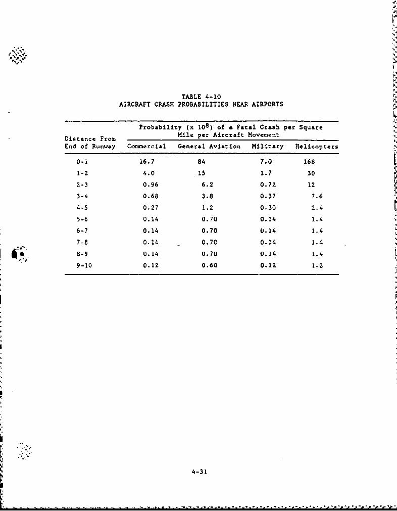
°.-.
TABLE 4-10AIRCRAFT CRASH PROBABILITIES NEAR AIRPORTS
Probability (x 108) of a Fatal Crash per Square
Distance From Mile per Aircraft Movement
End of Runway Commercial General Aviation Military Helicopters
0-i 16.7 84 7.0 168
1-2 4.0 15 1.7 30
2-3 0.96 6.2 0.72 12
3-4 0.68 3.8 0.37 7.6
4-5 0.27 1.2 0.30 2.4
5-6 0.14 0.70 0.14 1.4
6-7 0.14 0.70 0.14 1.4
7-8 0.14 0.70 0.14 1.4
O. 8-9 0.14 0.70 0.14 1.4
9-10 0.12 0.60 0.12 1.2
4-31
'.
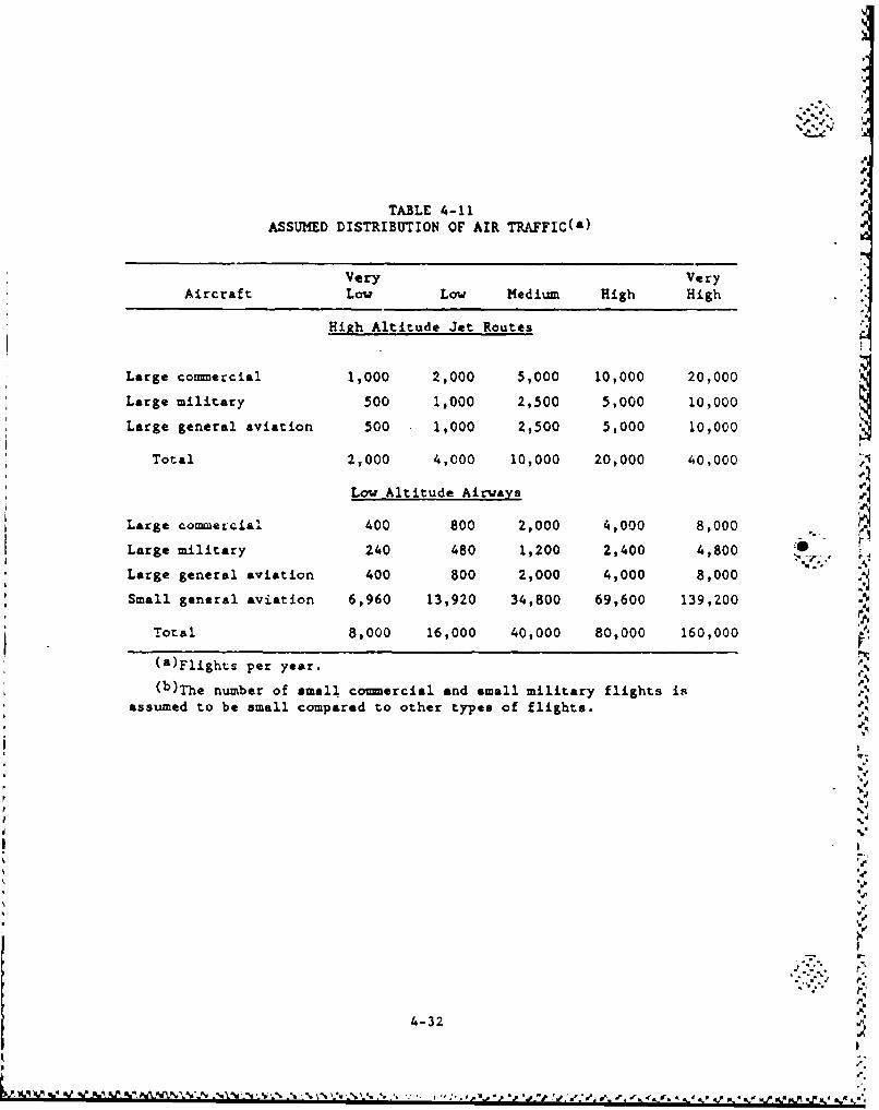
TABLE 4-11ASSUMED DISTRIBUTION OF AIR TRAFFIC(a)
Very VeryAircraft Low Low Medium High High
High Altitude Jet Routes
Large commercial 1,000 2,000 5,000 10,000 20,000
Large military 500 1,000 2,500 5,000 10,000
Large general aviation 500 1,000 2,500 5,000 10,000
Total 2,000 4,000 10,000 20,000 40,000
Low Altitude Airways
Large commercial 400 800 2,000 4,000 8,000
Large military 240 480 1,200 2,400 4,800 r
Large general aviation 400 800 2,000 4,000 8,000
Small general aviation 6,960 13,920 34,800 69,600 139,200
Total 8,000 16,000 40,000 80,000 160,000
(a)Flights per year.
(b)The number of small comnercial and small military flights isassumed to be small compared to other types of flights.
p..7
4-32
%X.
N %
Appendix C presents tables which summarize the input data that were
used to calculate the annual frequencies of both small and large air-
craft crashes at each of the eight sites. The frequencies were computed
using the equations given above. The annual frequencies for all the
sites and for large and small aircraft and helicopters are summarized inTable 4-12.
A major source of air crashes is the proximity of airports and
heliports. This is of particul&r concern at APG, PBA, and PUDA. The
air traffic for the APG analysis was supplied by PEO-PM Cml Demil
(Ref. 4-19). The belicopter air traffic at PEA was estimated by SAIC
(Ref. 4-12). The air traffic at PUDA was based on data collected at
Pueblo Memorial Airport and communicated to GA by telephone. The hell-
copter traffic at TEAD is light and was assumed to be 15 flights per
month.
The annual frequency of a crash into a speciflc facility is com-
puted by multiplying the appropriate frequency taken from Table 4-12 by
the effective target area of the facility (see Appendix C).
4.2.1.4. Meteorites. The frequency of meteorite strikes for meteorites
1.0 lb or greater is 4.3 x 10" 1 3 /ft 2 (Ref. 4-20). For small -ateorites
(a ton or less), stone meteorites are approximately ten times more
co on than iron meteorites (Ref. 4-21). However, iron meteorites are
more dense and tend to have higher impact velocitiGs, and consequant?.y,
represent a significant portion of the total meteorites that can rupture
munitions. Table 4-13 shows the size distribution of striking meteor-
ites for both iron and stone meteorites. The table was compiled from
the data presented in Refs. 4-20 and 4-21.
4-33
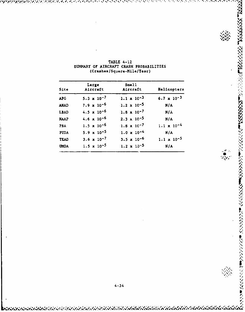
TABLE 4-12SUMMARY OF AIRCRAFT CRASH PROBABILITIES
(Crashes /Square-Mile/Year)
Large SmallSite Aircraft Aircraft Helicopters
APG 5.3 x 10⁻⁷ 1.1 x 10⁻³ 6.7 x 10⁻³
ANAD 7.9 x 10i 6 1.2 x 10⁻⁵ N/A
LBAD 4.5 x I0-6 1.8 x 10⁻⁷ N/A
NAAP 4.6 x 10⁻⁶ 2.3 x 10⁻⁵ N/APBA 1.5 x 10⁻⁶ 1.8 x 10⁻⁷ 1.1 x 10 -4
PUDA 5.9 x 10⁻⁵ 1.0 x 10⁻⁴ N/A
TEAD 3.6 x 10⁻⁷ 3.5 x 10⁻⁶ 1.1 z 10- 5
UMDA 1.5 x 10⁻⁵ 1.x N/A
4-34
S
J.
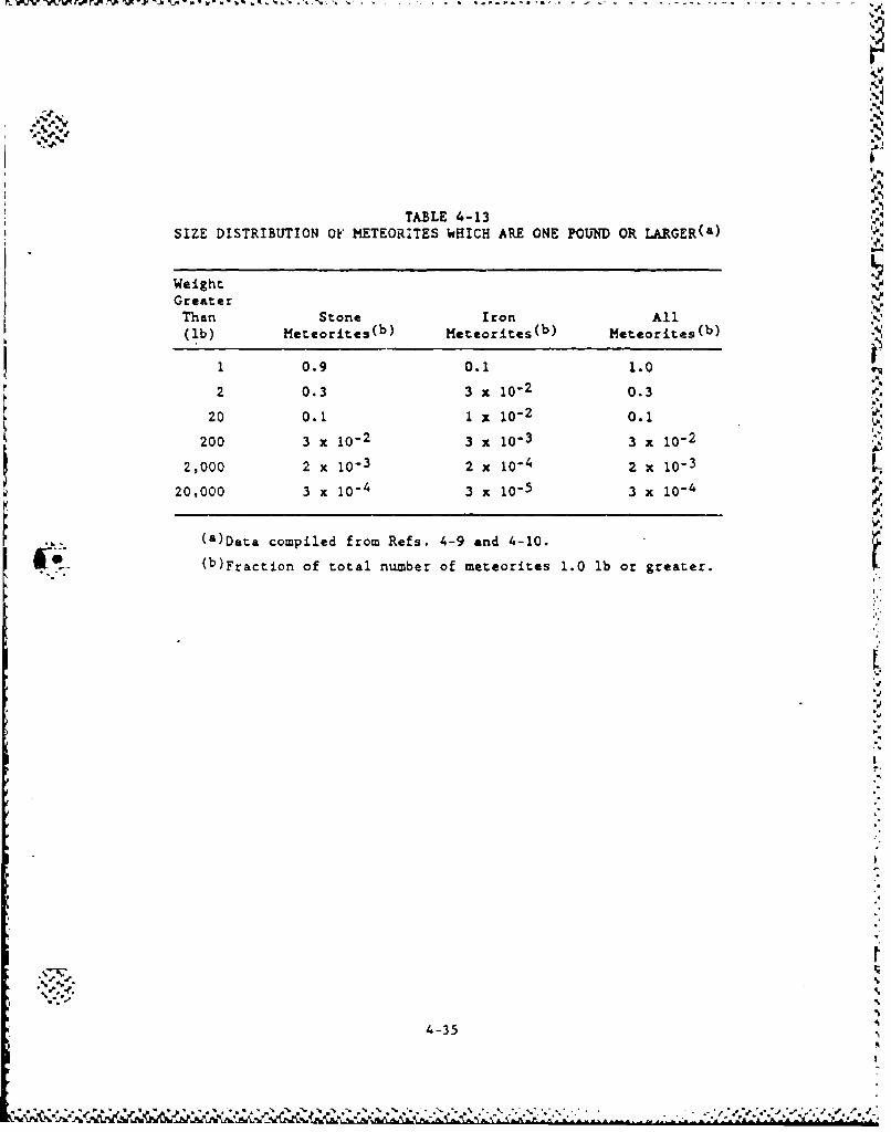
.r.'% p x -A
TABLE 4-13SIZE DISTRIBUTION OF METEORITES WHICH ARE ONE POUND OR LARGER(&)
WeightGreater
Than Stone Iron All(ib) Meteorites(b) Meteorites(b) Meteorites(b)
1 0.9 0.1 1.02 0.3 3 x 10⁻² 0.3
20 0.i 1 x - 0d 2 0.-200 3 x 10⁻² 3 x 10⁻³ 3 x 10⁻²
2,000 2 x 10⁻³ 2 x 10⁻⁴ 2 x 10-320,000 3 x 10⁻⁴ 3 x 10⁻⁵ 3 x 10⁻⁴
• -(a)Data compiled from Refs. 4-9 and 4-10.
(b)Fraction of total number of meteorites 1.0 lb or greater.
bd
4-35
.- L.V b.. a-- - : '/,?. A
4.2.2. Internal Eents k"
Table 4-14 aullarizea the internal initiating events for the con-
tinued storage option. Also summarized in the table are the event
occurrence frequencies. The bases for these frequencies are discussed
in Section 5 and are not repeated here.
43
* -.-'.-
"-÷ ..-
4-36
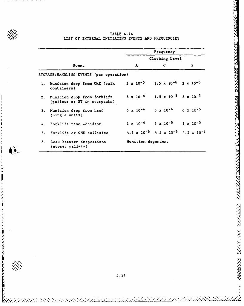
°4.
AA.'
TABLE 4-14LIST OF INTERNAL INITIATING EVENTS AND FREQUENCIES
Frequency
Clothing Level
Event A C F
STORAGE/HANDLING EVENTS (per operation)
1. Munition drop from CHE (bulk 3 x 10⁻⁵ 1.5 x 10⁻⁶ 3 x 10⁻⁶containers)
2. Munition drop from forklift 3 x 10⁻⁴ 1.5 x 10.5 3 x 10⁻⁵(pallets or ST in overpacks)
3. Munition drop from hand 6 x 10⁻⁴ 3 x 10⁻⁴ 6 x 10⁻⁵(single units)
4. Forklift tine .-cident 1 x 10- 5 x 10⁻⁵ 1 x 10⁻⁵
5. Forklift, or CHE collision 4.3 x 10⁻⁶ 4.3 x 10- 6 4.3 x 10⁻⁶
6. Leak between inspections Munition dependent 4.
A (stored pallets)
LL
I.
4-37
m° . '
, • . . . . . - - . . . '- " . . . . . . ' " ' -
4.3. REFERENCES
4-1. U.S. Nuclear Rogulatory Commission, "PRA Procedures Guide,"
NUREG/CR-2300, 1982.
4-2. Fraize, W., et al., "Preliminary Risk Analysis Supporting theChemical Weapons Stockpile Disposal Program (CSDP), Vol. 1:
Analysis' The MITRE Corporation, MTR-86W4-01, May 1987.
4-3. Fraize, W., at al., "Preliminary Risk Analysis Supporting the.
Chemical Weapons Stockpile Disposal Program (CSDP), Vol. 2:
Appendices" The MITRE Corporation, MTR-86W4-02, May 1987.
4-4. Arthur D. Little, In:., "Analysis of Risks Associated With Opera-
tion on Onsite M55 Rocket Demilitarization Plants," U.S. Army
Toxic and Hazardous Materials Agency, M55-OD-3, May 1985.
4-5. Arthur D. Little, In-., "Analysis of Risks Associated with Opera-
tion of the JACADS M55 Rocket Demilitarization Plant," U.S. Army
Toxic and Hazardous Materials Agency, M55-OD-9, May 1985.
4-6. Arthur D. Little, Inc., "Analysis of Converted M55 Rocket Demili-
tarization Plant at Pine Bluff Arsenal," U.S. Army Toxic and
Hazardous Materials Agency, M55-OD-lO, May 1985.
4-7. Arthur D. Little, Inc., 'Analysis of Risks Associated with Opera-
tion of the CAMDS M55 Rocket Demilitarization Plant," U.S. Army
Toxic and Hazardous Materials Agency, M55-OD-11, May 1985.
4-8. Arthur D. Little, Inc., "M55 Rocket Separation Study," U.S. ArmyToxic and Hazardous Materials Agency, M55-OD-08, November 1985.
4-9. The Ralph M. Parsons Company, 'JACADS-Preliminary Hazards Analy-
sis of Final Concept Design," Task G-56 Interim Report, May 1983.
4-10. The Ralph M. Parsons Company, "Fault Tree Analysis, Johnston
Atoll Chemical Agent Disposal System," Task G-SC, U.S. Army
Engineers Division, February 1985.
4-11. Rhyne, W. R., et al., "Probabilistic Analysis of Chemical Agent
Release During Transport of M55 Rockets,' H&R Technical Associ-
ates, Inc., Prepared for USATHAMA, M55-OD-4, H&R 255-1, September
1985.
4-38I - . . . . .. . . . . -, . . . . , ., , . . • - , .$ , . . . . -- . . -j o . . . . - • ..... . .
-IP. 4-12. Science Applications International Corporation, "Probabilities of%h
Selected Hazards in Disposition of M55 Rockets," U.S. Army Toxic
and Hazardous Materials Agency, M55-CS-2, November 1985.
4-13. Uniform Building Code, International Conference of Building
Officials, 1985.
4-14. "Technical Manual, Seismic Design for Buildings," TM 5-809-10,
Department of the Army, the Navy, and the Air Force, February
1982.
4-15. "Tentative Provisions for the Development of the Seismic Regula-
tions for Buildings," Applied Technology Council, ATC 3-06, NBS
SP-510, NSF 78-8, June 178.
4-16. "Standard for Estimating Tornado and Extreme Wind Characteristics
at Nuclear Power Sites," ANSIIANS-2.3-1983, 1983.
4-17. Coats, D. W., "Natural Phenomena Hazards Modeling Project:
Extreme Wind/Tornado Hazards Model for Department of Energy
Sites," UCRL-53526, Lawrence Livermore National Laboratory,
February 1984.
"4-18. "USNRC Standard Review Plan," Section 3.5.1.6, "Aircraft"Hazards," U.S. Nuclear Regulatory Commission, NUREG-0800, July
1981.
4-19. Memo from OPMCM to GA Technologies Inc., November 20, 1986.
4-20. Solomon, K. A., K. C. Erdmann, and D. Okrent, "Estimate of the
Hazards to a Nuclear Reactor From the Random Impact of
Meteorites," Nuclear Technology, Vol. 25, January 1975.
4-21. Blake, V. E., "A Prediction of the Hazards From the Random Impact
of Meteorites on the Earth's Surface," Sandia Laboratories
SC-R.R-68-838, December 1968.
I4-39
a, 4-39
'1%
5. SCENARIO LOGIC MODELS FOR STORAGE
5.1. SEQUENCE LIST AND EVENT TREES
The accident scenarios involving the interim storage of chemical
munitions were categorized as follows:
1. External event-induced agent releases (e.g., earthquakes, air-
craft crashes, etc.).
2. Releases due to leakage of munitions while in storage.
3. Releases from accidents that could occur during the isolation
of leaking munitions while in storage.
4. Releases from accidents related to tbe handling of munitions
during maintenance and surveillance.
For the first category (i.e., external events), the selection pro-
cess described in Section 4.1 identified six initiating event families.
These aLe discussed in Section 5.2. For the other categories (i.e.,
internal initiating events), there is one initiating event family for
each category. A Lotal of nine initiating event families resulted, as
listed in Table 4-2. For each family, there were one or more specific
sequences which were analyzed. Table 5-1 presents the list of accident
sequences identified aid evaluated for the continued storage option.
Table 5-2 lists the v.quences screened and gives the basis for the
screening.
The event tree models are shown in Figs. 5-1 through 5-5. They
will be discussed in the following sections by initiating event* .-. ' .
5-1 9.
S %
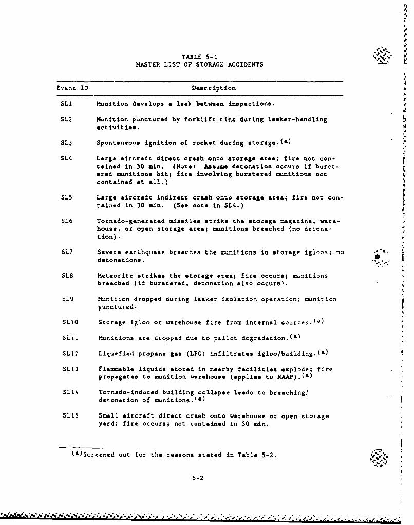
-I
TABLE 5-1MASTER LIST OF STORAGic ACCIDENTS
Event ID Deascription
SLU Munition develops a leak between inspections.
SL2 Munition punctured by forklift tine during leaker-handlingactivities.
SL3 Spontaneous ignition of rocket during storage.(a)
SL4 Larg4 aircraft direct crash onto storage area; fire not con-tained in 30 min. (Note: Assume detonation occurs if burst-ered munitions hit; fire involving burstered munitions notcontained at all.)
SL5 Large aircraft indirect crash onto storage area; fire not con-tained in 30 min. (See note in SL4.)
SL6 Tornado-generated missiles strike the storage magazine, ware-house, or open storage area; m.nitions breached (no detona-tion). w
SL7 Severe earthquake breaches the munitions in storage igloos; nodetonations.
SL8 Meteorite strikes the storage area; fire occurs; munitionsbreached (if burstered, detonation also occurs).
6L9 Munition dropped during leaker isolation operation; munirionpunctured.
SLIO Storage igloo or warehouse fire from internal sources.(a)
SLii Munitions are dropped due to pallet degradation.(a)
SL12 Liquefied propane gas (LPG) infiltrates igloo/buiiding.(a)
SL13 Fla-able liquids stored in nearby facilities explode; firepropagates to munition warehouse (applies to NAAP).(a)
SL14 Tornado-induced building collapse leads to breaching/detonation of munitions.()
SLI5 Small aircraft direct crash onto warehouse or open storageyard; fire occurs; not contained in 30 min.
(a)Scr-ened out for the reasons stated in Table 5-2.
5-2
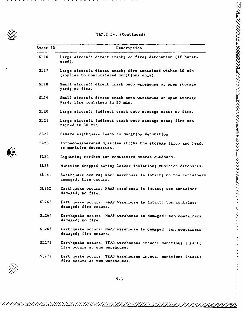
TABLE 5-1 (Continued)
Event ID Description
SL16 Large aircraft direct crash; no fire; detonation (if burst-ered).
SL17 Large aircraft direct crash; fire contained within 30 min(applies to nonburstered munitions only).
SL18 Small aircraft direct crash onto warehouse or open storage -
yard; no fire.
SL19 Small aircraft direct crash onto warehouse or open storageyard; fire contained in 30 min.
SLZO Large aircraft indirect crash onto storage area; no fire.
1%.
SL21 Large aircraft indirect crash onto storage area; fire con-tained in 30 min.
SL22 Severe earthquake leads to munltion detonation.
SL23 Tornado-generated missiles strike the storage igloo and 3eadi. to munition detonation.
SL24 Lightning strikes ton containers stored outdoors.
SL25 Munition dropped during leaker isolation; munition detonates.
SL261 Earthquake occurs; NAAP warehouse is intact; no ton containersdamaged; fire occurs.
SL262 Earthquake occurs; NAAP warehouse is intact; ton containerdamaged; no fire.
SL263 Earthquake occurs; NAAP warehouse is intact; ton containcrdamaged; fire occurs. L
EL264 Earthquake occurs; HAAP warehouse is damaged; ton containersdamaged; no fire.
SL265 Earthquake occurs; NAAP warehouse is damaged; ton containersdamaged; fire occurs.
7
SL271 Earthquake occurs; TEAD warehouses intact; munitions ints:t;fire occurs at one warehouse.
SL272 Earthquake occurs; TEAD warehouses intact; -munitions intact;fire occurs at two warehouses.
5-3
%. % %i
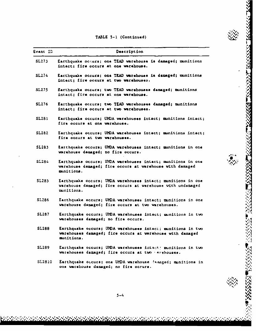
TABLE 5-1 (Continued)
Event ID Description
SL273 Earthquake occurs; one TEAD warehouse is damaged; munitions
intact; fire occurs at one warehouse.
SL274 Earthquake occurs; one TEAD warehouse is damaged; mnnitionsintact; fire occurs at two warehouses.
SL275 Earthquake occurs; two TEAD warehouses damaged; musnitionsintact; fire occurs at one warehouse.
SL276 Earthquake occurs; two TEAD warehouses damaged; -munitionsintact; fire occurs at two warehouses.
SL281 Earthquake occurs; UMDA warehouses intact; munitions intact;fire occurs at one warehouse.
SL282 Earthquake occurs; UMDA warehouses intact; munitions intact;fire occurs at two warehouses.
SL283 Earthquake occurs; UMDA warehouses intact; munitions in onewarehouse damaged; no fire occurs.
SL124 Earthquake occurs; UMDA warehouses intact; munitions in one "*.'warehouse damaged; fire occurs at warehouse with damagedmunitions.
SL285 Earthquake occurs; UMDA warehouses intact; munitions in onewarehouse damaged; fire occurs at warehouse with undamagedmunitions.
SL286 Earthquake occu's; UHDA warehouses intact; munitions in onewarehouse damaged; fire occurs at two warehouses.
SL287 Earthquake occurs; UMDA warehouses intact; munitions in twowarehouses damaged; no fire occurs.
SL288 Earthquake occurs; UMDA warehouses intact; munitions in twowarehouses damaged; fir* occurs at warehouse with damagedmuanitions.
SL289 Earthquake occurs; UMA warehouses intA,:•. munitions in twowarehouses damaged; fire occurs at two ,Arehouses.
SL2810 Earthquake occurs; one UMDA warehouse !%inaged; munitions inone warehouse damaged; no fire occ-urs.
5-4
U,. * . "+ . . .'", '."b " U'. "wU' V%.. , ',. ',:, % ".:.% . .'.% . . . . . . . .% ". . " -.' -. - -P•+,' m. .- •" ?.' .+r . .'+,.• DP • •-•,•'• ,. .' .- ,..._t...• .m.a +..• d+.,+ .t. ....
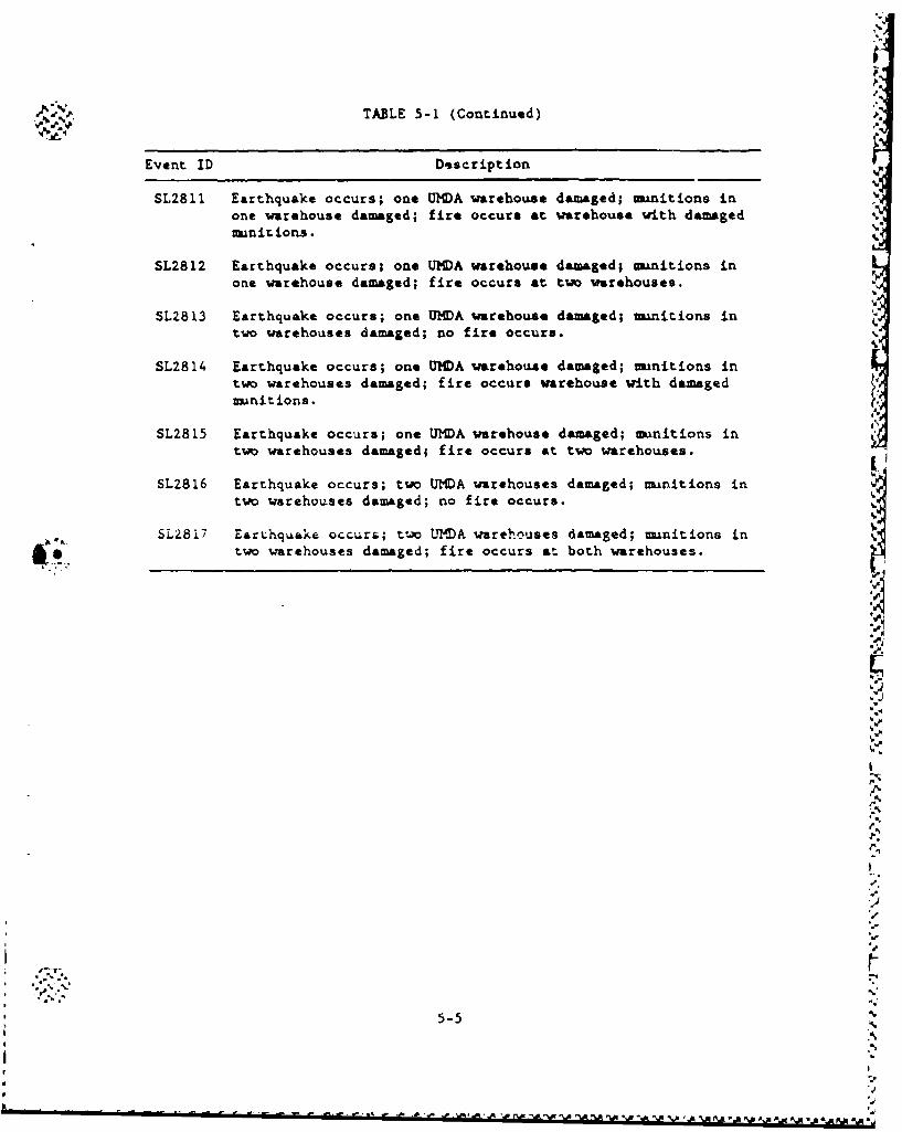
TABLE 5-1 (Continued)
Event ID Description
SL2811 Earthquake occurs; one UHDA warehouse damaged; munitions inone warehouse damaged; fire occurs at warehouse with damagedmanit ions.
SL2812 Earthquake occurs; one UMDA warehouse damaged; munitions inone warehouse damaged; fire occurs at two wrehouses.
SLZ813 Earthquake occurs; one UMDA warehouse damaged; Lmnitions intwo warehouses damaged; no fire occurs.
SL2814 Earthquake occurs; one UMDA warehouse damaged; minitions intwo warehouses damaged; fire occurs warehouse with damagedmunitions.
SL2815 Earthquake occurs; one UMDA warehouse damaged; munitions intwo warehouses damaged; fire occurs at two warehouses.
SL2816 Earthquake occurs; two UMDA warehouses damaged; munitions in
two warehouses damaged; no fire occurs.
)Los SL2817 EarLhquake occur&; tv UMtA warehouses damaged; munitions in
. •two warehouses damaged; fire occurs at both warehouses.
/4
-.WO
.4%
5-54
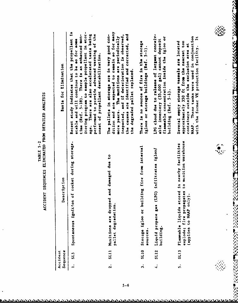
.0 U
1*4 A£ 0~n a 0 *
.0"W 6 i0. 6~ 0 a9*2J 4~ 14 0 41 0a6h-
uaC 0 hi4h u *be 0.4 0q4d@ 0i u0. 0a
whd A ~ a a c0 w0 a U 4 0~CL ~0 C @ 4 c. 04 bO"q0 . a Q-0 i
4w aC&J P c0 4.. -4
0 0.- 0 J .0. 0 Av4 "4 ioo 41 C~m .0 a0 0 W0 "4
.4 ~ L 4JE O. 41 * -1J 00.4O- .4 i4 C 4 4 .4Cc
10 &h 0 .g . a 0 Id Ibd0 W4I-
41 4Jg 6-4fJQ i 4 1 0 "4 4-4 .44 wl a* 0 I
c V &J0. U U'4is 40 Q e. 0 0 h
*Oa0 0 19 000-V .4& .4 134. Q 0. 0 -0.V) -4"q f- id t O41 % 4Jr.I
0o 4O w0. " 1
* 1 64, b 04 0U ~ AO 1 0 ah 0E @0 4L -0 . 4 h i 41 64 h 0h 0 0 do . C 1Q 0
c Go .0 6 0 c
00 4 01 4 v 6 r-4 4 4 6 0 Z:0 V~-4 ac o
m1 oo f .J 0 .40 &Jz i - c "1-0 a -~4
r %va -0 - q .0 x0. 04 W4 0 4 v -v &.
61~ 4& 4 D s-6 ASbo 00 CL 0
.44an V4. 0
0
.4 C
.4 -4 100
z~1 .0 'a .i 41l 0 IN w 4
70 60 ..J C0-4 41 w
hiE V..4
an W '41ov 60 tohi *
41, CV 61. 01 40 00 C1 .44
0 .4 61 an 1 ~0 w.
C *a- 0 - S
a 0-4 0- U 4 00 .0.o 6 a0 04 44 &J0 f
0J4 Q' "4.
- -4 -4 CA
&j - -4 :3.,4
5-6 46I
5-6-
Vký,LXUAýN'*AýNd
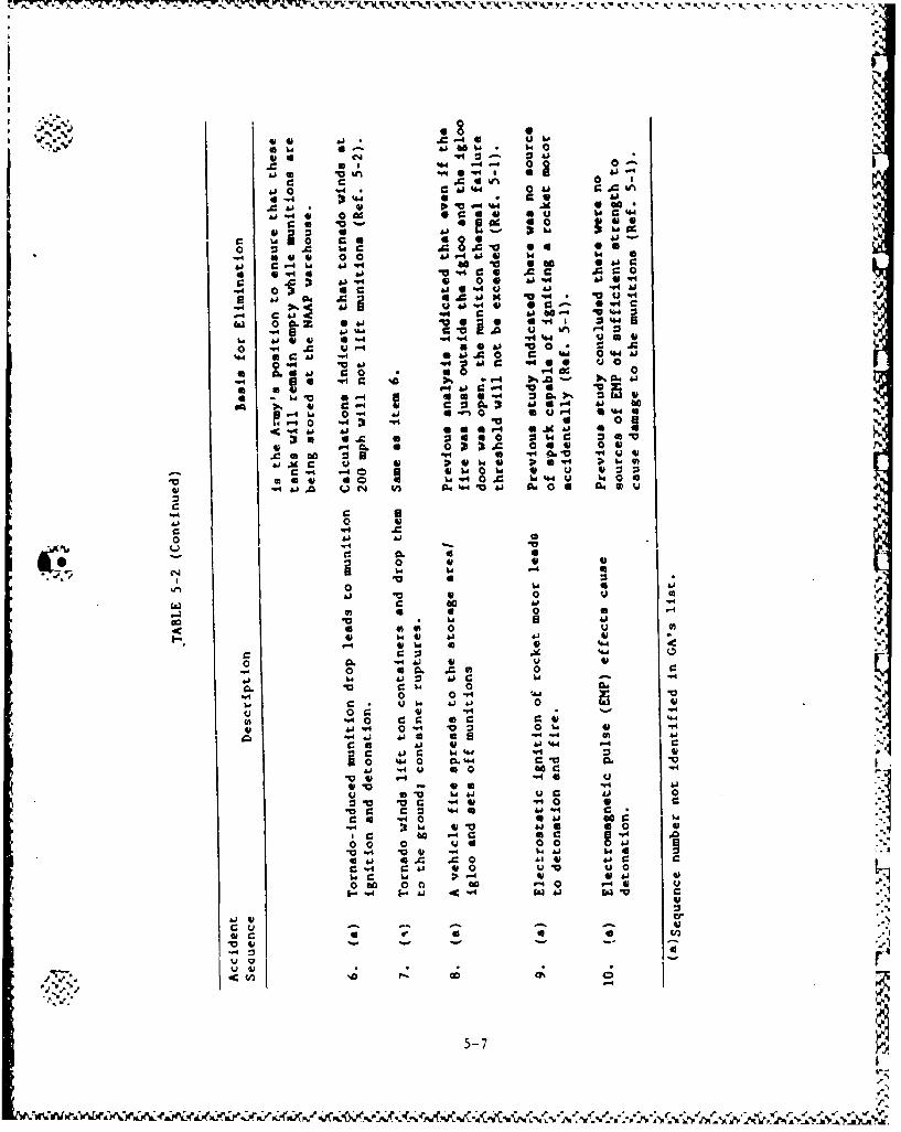
01 C A4 44
Aj-
4.4 At. 0 A O4
014 0~ C
CO~4 'a U0~ 0 6
b. A jW ~ .
0 uUO CU 00
0~ a -4 0~ g ' 0 0-4G 66 1 00-416 14 .
* 0-46 41 'a4. AC A
-4 6a 0 A *- 06 a.1 r- %41
V-4 0 "41 V~a aC~ idAj Go C 40-4 'a4
31 1d1 C -
o . A 414 804 '0 A"6044 41A0 C U 044as.96 .0 W4 V 4 ~ -~ O4
c 04 i 4' 0 0 %
41 44 41 ad 00a 046
£6~ 6 4 .a 44r
-4 ~0
041J 41. 1* -
'a 0
0 140 0 441 a 0 4.
(.4~: lZ041'a 0
40r 0a * 4
60 0 0 0I- 44 41 01
41.A 44 0 ud .
04 6 0. .0001.. 41A4 44 -
'94~ 0 04'
41 00 41 -4. - 1
Ch 0i CC r.L1410 0 a 0 .~~~~- C .4 4 -
0 440 0." Ca 0 . '410.4 Q -441 -.4 go
41' 41 66 0
0 0 0 41 00 , I-4 -4 41 A 4030
04 0£10'4 1
0-4 044 410415-71
AN. 1.4 6k -A4 AN6
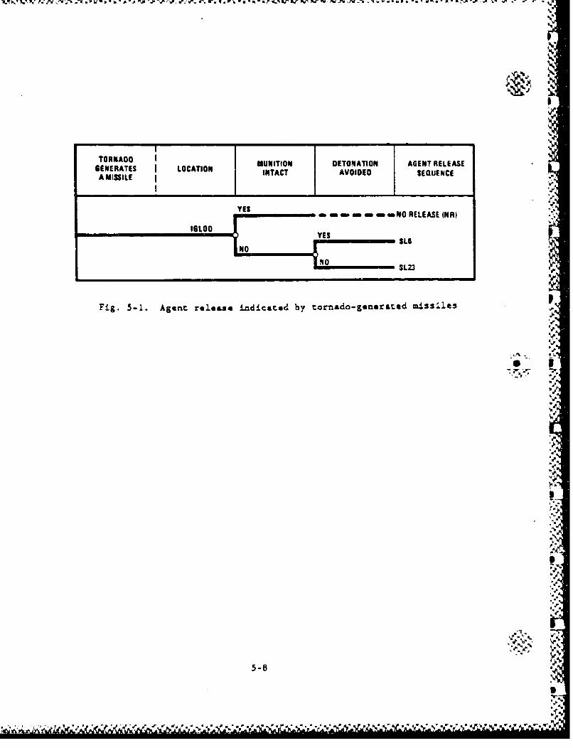
GENRNATE OOTO MUNITION DETONATION AGENT RELEASEBEMISIEAT I OCTN INTACT AVOIDED SEDUENCE
-w imamin em oNO RELEASE INR)
1010 SL23
Fig. 5-1. Agent release indicated by tornado- generated aissi~les
5-8
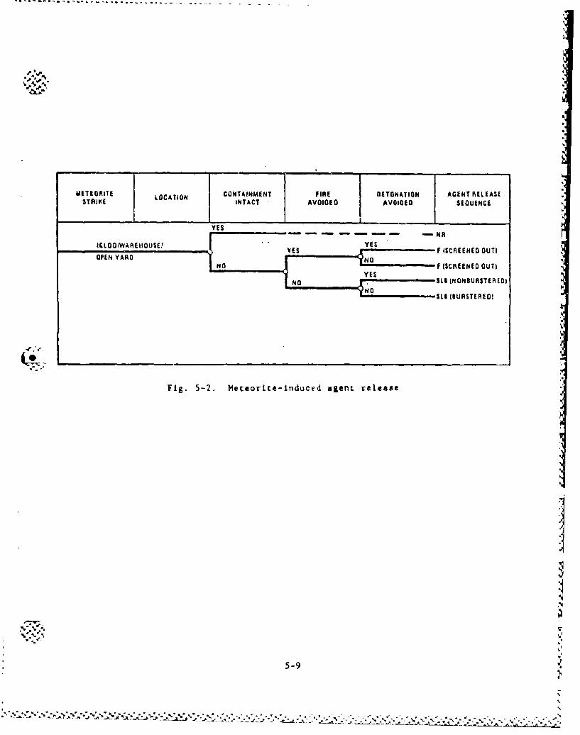
METIEGRIIE LOCATION CONTAINMIENT FIRE DETONATION AG•ENT RE.L(AStSTRIKE I INTACT AVOIDED i AVOIDED SIOUIENCE
NOSl (NONOURSTERED)
Fig. 5-2. Meteorice-induced agent release
Y E S... .. .. -
5-9
' U'N . .,.,vO~-'*-- ... >..*~ NO , F {SCREENEDX . .UT ;-"
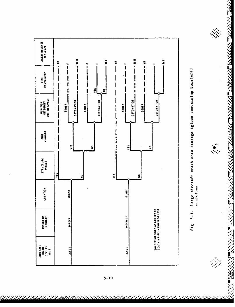
4-4'
a-'a
Sa at i i
a lislow
'"a IIwoI * I I 6
4AI i II 640a I I I I ' 'p
I * I4AI
a a a
5-10
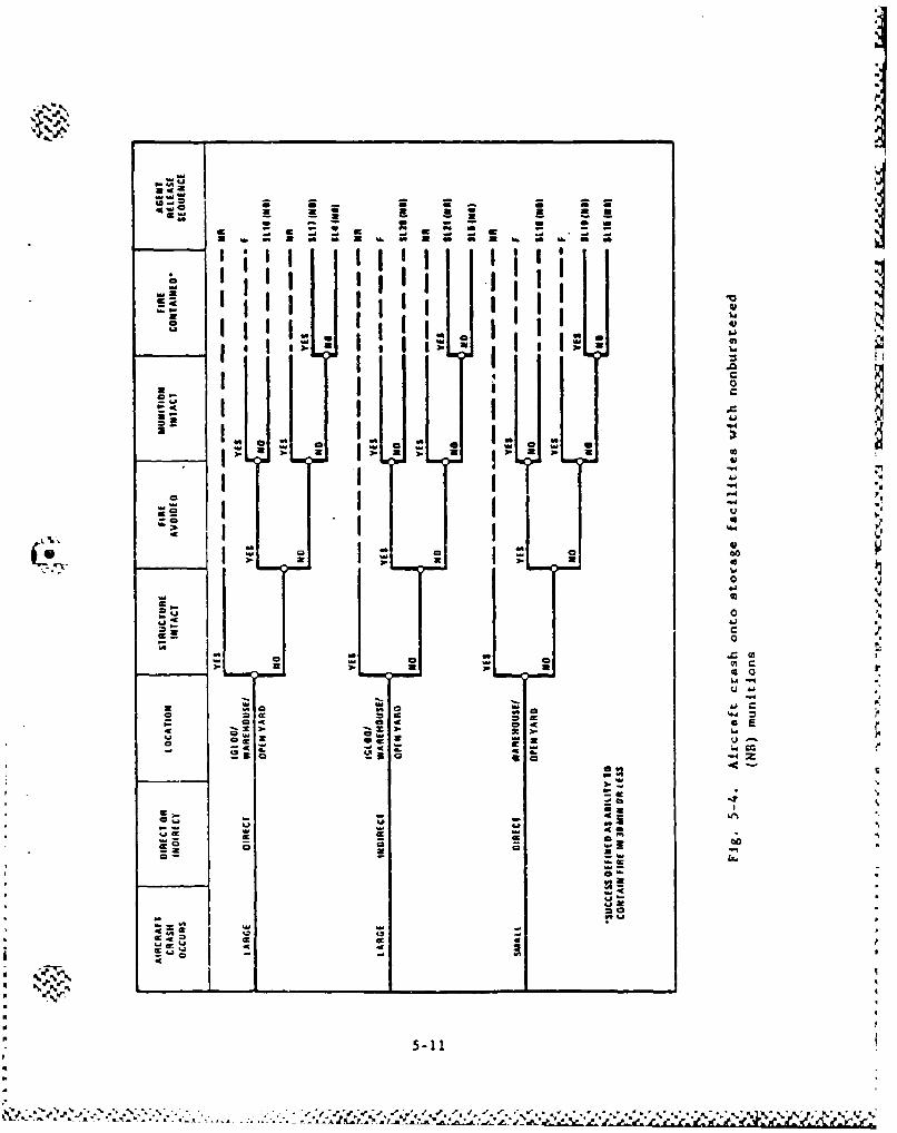
zp
S~U U U - U
- -It
- - - -
1 I..
I4w CCc
5-11
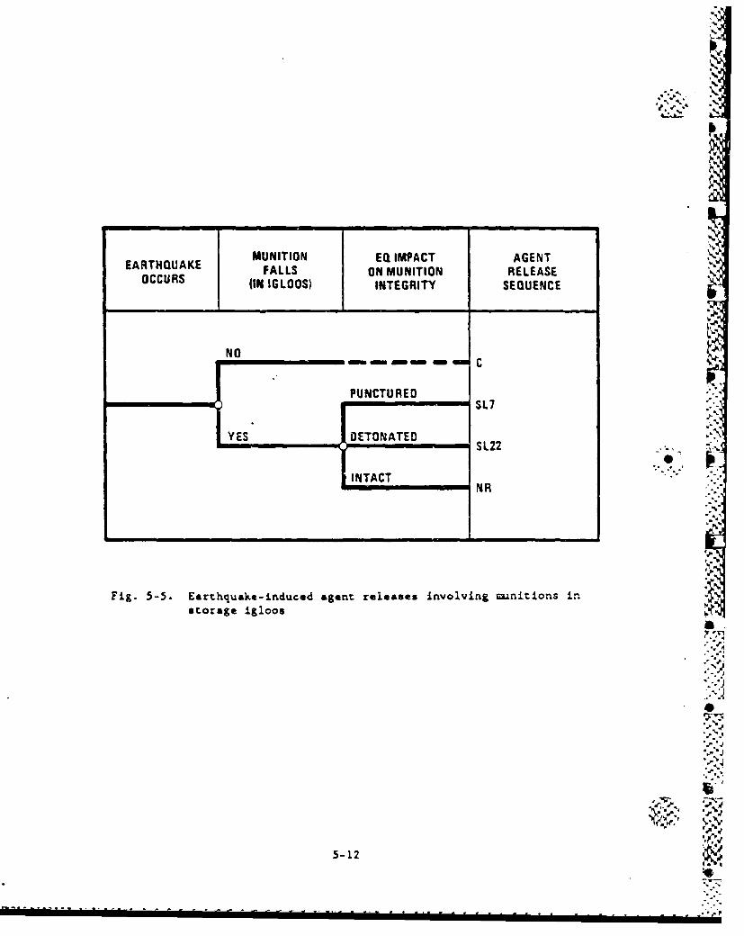
MUNITION EQ IMPACT AGENTEARTHQUAKE FALLS ON MUNITION RELEASEOCCURS (IN IGLOOS) INTEGRITY SEQUENCE
NO
PUNCTURED "•SL7
YES* DETONATED •%
,- SL22
INTACT, NR ;":" •!
N"R
Fig. 5-5. Earthquake-induced agent releases involving munitions inrstorage igloos
"'y"I•
5-12
,_•.• category. In these even: trees, NR refers to no release of agent, and F
4 or low consequence, respectively.
w U'I
,i
(
* .,
-44
I5-1I'
*|
.- '
5.2. EXTERNAL EVENTS I.W
The external events that wsre evaluated include:
* Tornadoes and high rnias.
* Meteorite strikes.
0 Aircraft crashes.
"* Earthquakes.
"* Lightnings.
"Fhoods.
In general, the auount ,f agent released to the atmosphere from
accidents induced by such events depends on the extent of damage
incurred to the building structure and the munition itself. The muni-
tions are currently stored in igloos, warehouses, or open storage yards.
Section 3 discusses the types of storage structures present at each
CONUS site, as well as the kinds of munitions stored.
5.2.1. Tornadoes and High Winds
The accident scenarios identified involve the breaching of the
munitions in the storage facilities (i.e., igloos, warehouses, or open
ya;-d) by tornado- or high-wind-generated missiles. This failure umode
was determined to be more credible than that identified in sequence
SL14, which is a tornado/high-wind-induced building collapse that could
lead to the crushing of unLitions by the falling structure. For UBC-
designed structures such as a warehouse, the wind loads will fail the
walls of the structure before the structure will collapse. Storage
igloos have been designed to resist the direct effects of tornadoes with
winds up to 320 mph except for the possibility of missiles breaching the
igloo doors (Ref. 5-1). For the above reasons, seq-1ence SL14 has been
screened out from further analysis.
5-14
'A The event tree developed to define relevant accident sequence3 is
shown in Fig. 5-1. Neither of the accident sequences (SL6 and SL23)
could be screened out initially as more detailed quantitative analysis
is required to determine the necessary wind velocity to generate mis-
silos which could penetrate the munitions. Hence, both accident
sequences shown in the event trees wre quantified.
Essentially, the missile penetration of the mtanition occurs if
(1) a tornado or extremely high wind occurs with a velocity sufficient
to generate a missile that could penetrate the igloo door, warehouse
wall, or transportation container wall, and the mnition itself; and
(2) the missile actually hits the target munition.
The probability of a missile hitting and rupturing a munition is
the product of four variables: (1) the probability that the 7elocity
vector of the missile is nearly perpendicular to the target; (2) the
probabiliry that the missile is oriented properly to penetrate the tar-
Sget; (3) the number of missiles per square foot of wind; and (4* the
target area. More details on the derivation of these variables are
provided in Appendix C and Ref. 5-2.
If the missile hits a burstered -mnition, two failure modes are
possible: (1) the munition is opened up due to puncture or crush, or
(2) the missile impact causes munition detonation due to the application
of a force greater than the "undue force." The undue force is deiirned
as "a force greater than that generally required to A-semble the Muni-
tion" or as "any force which could cause deformation to the -znition
(other than minor surface deformation) or damage to the explosive train"
(Ref. 5-3).
5.2.1.1. Storage Mas.tzines. The analysis of the vulnerability of the ¶
igloo door to the tornado-generated miss'le considered the two types of
igloo doors present at the CONUS sites, i.e., steel and concrete. PBA
and TEAD have igloos with either steel or concrete doors, while the
%
5-15
I;
igloos at ANAD, LBAD, PUDA, and UtDA have steel doors only. For con-
servatism, all igloos at PBA and TEAD were assumed to have concrete
igloo doors.
The steel doors require a missile velocity of 94 mph for penetra-
tion by a 3-in. steel pipe or 66 vyh for penetration by a utility pole.
for the concrete doors, the penetration velocity for a 3-in, steel pipe
is 66 mph and for the utility pole, 54 mph. After penetrating the 6oor,
th. remaining missile velocity must be large enough to rupture the muni-
tion. The formula for the required initial aissile velocity is as
fclllow,:
• VI = V + V m , (5-1)
where VI - Y.'equired initial velocity,
d - "requirad velocity to pene. rate the door,
Vm required velocity to rupture the uunition.
In order for a missile to reach the velocity required to penetrate -- "
the igloo door and the munitions inside, a wind with a significantly
higher velocity is required. Table 5-3 presents the relationship
between wind velocity and missile velocity.
The frequency of a wind-generated missile penetrating an igloo and
a munition inside the igloo, is the product of the following:
1. The frequency of a tornado or wind which has sufficient
velocity to generate a missile that can penetrate the igloo
and munition.
5-16
•:":'•_."./.?.:-".:.-..:.••-_.:i.?• ---••"•-- .:.. -." : .--: •- - -"/ '-i----/ -?• -?• .:'?••.'•?-• :''"'?".• -?••:-S
TABLE 5-3WINDBORNE MISSILE VELOCITIESCC)
Hoýitzontal missile Velocity(b)(uph) Maximum Haight
Design Wind Speed 100 150 200 250 300 350 (ft)
Timber plank 60 72 90 100 125 175 200
Three-inch-diameter 40 50 65 85 110 140 100standard pipe
Utility pole (c) (c) (c) 80 100 130 30
Automobile (c) (c) (c) 25 45 70 30
(a)Source: Ref. 5-4.(b)Vertical velocities are taken as 2/3 the horizontal missile veloc-
ity. Horizontal and vertical velocities should not be combinedvectorially.
(c)Missile will not be picked up or sustained by the wind; however,
- for this analysis, any initial missile velocity of 80 mph or less wasassigned a wind velocity vi 250 mph.
5-17
Z. The probability of a missile penetrating the igloo and hitting
the munition in such a way as to cause damage and is calcu-.
lated as follows:
Pp Pd x 7o m De x At , (5-2)
where Pd " probability that the velocity of the missile is
nearly perpendicular to the target plane,
Po " probability that the missile is oriented to pene-
trate the target (i.e., missile not tumbling or
going sideways),
De density of number of missiles per square foot of
wind,
- target area.
Details on the calculation of these variables are given in " -
Ref. 5-2.
The site-specific tornado frequency versus velocity curves has
been presented in Section 4. Two types of missiles were initially con-
sidered: (1) a 3-in. pipe and (2) a utility pole. For all wanition
types, it was found that the utility pole had a higher probability of
penetrating munitions.
Tables 5-4 and 5-5 present the wind velocities required to generate
missiles which have sufficient velocity to penstrate the igloo door and
the various munitions stored inside. Table 5-6 presents the annual fre-
quencies of these winds occurring at each of the sites that have igloos.
The frequencies were read from the curves presented in Figs. 4-9 through
4-11. The conditional probability of a missile hitting the igloo door
and the munitions stored inside is 3.2 x 10⁻⁶ (see Appendix C).
-A,5-18
............. .. . . . . . .. . . . . ....-
"4~
"4 6 0.
%n9
.441~~~ON 4WI Ou ''40 C C~
4A
b d. & j,j "
c 00' '-44
4.r q- .- O %
61 > 0 A CIO N~0 Vl fn Q%¶4 g
.4.040 aC1
4~.j
w
06GAV)
wq..
14 r.---4C -"4 hi- 4 -4 - 4 4
c010
.199
I-so Go
o 5-19
-u lk 11 - 'R - Mb.WI - L -N
go aN Q 4" 0
en C4 C14 (4 UIC'4 V% C4 NC104 C14 C4
-A 0zn C -4m j.. IV
S C-* '4 c0- go- %A4 N G -*
:0
-e .04-
c0
m X CO ý 0 0'Q '0en C4 4l mý C4
to
C6 :b % 0 .3
eC ..4 1. 4 '. 4 C. .
a 4 *-A *-4 .- 4 .-"4%4 .- 4 .- 4 Cbd
I4 I4 I,- Aj I.- C - 4 a- ACV
fn en* fni 0 4 fn* 0 -4
61 4
-4 -- l0 40
-e'4 -4 14 %
%n C .44 ~ ~ ~ f cc0 9 e 9 *
5-20
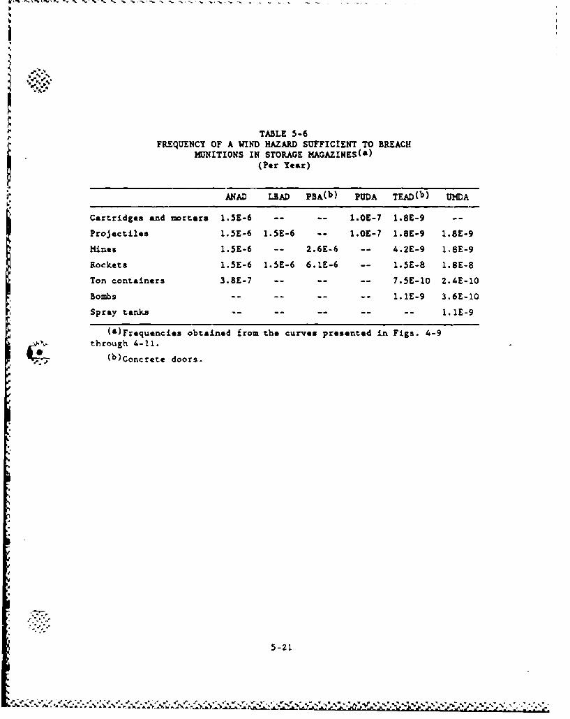
TABLE 5-6FREQUENCY OF A WIND HAZARD SUFFICIENT TO BREACH
MUNITIONS IN STORAGE MAGAZINES(W)(Per Year)
ANAD LBAD PBA(b) PUDA TEAD(b) UMDA
Cartridges and mortars 1.5E-6 .. .. 1.OE-7 1.8E-9 -
Projectiles 1.5E-6 1.5E-6 -- 1.OE-7 1.8E-9 1.8E-9
Mines 1.5E-6 -- 2.6E-6 -- 4.2E-9 1,8E-9
Rockets 1.5E-6 1.5E-6 6.1E-6 -- 1.5E-8 1.8E-8
Ton containers 3.8E-7 .. .. . 7.5E-10 2.4E-10
Bombs .. .. .. .. 1.1E-9 3.6E-10
Spray tanks .. .. .. .. .. 1.IE-9
(a)Frequencies obtained from the curves presented in Figs. 4-9"through 4-11.
(b)Concrete doors.
ii 5-21.
1 .. . *-'~ ~ S **S ~
5.2.1.2. Warehouses. The warehouses at TEAD are designed for 100-mph vo•
wind loads (Ref. 5-1). Assuming that the warehouses at NAAP and UMDA
are designed to the UBC requirements, they should be designed for at
least 70 mph winds. An analysis of the UBC requirements shows that A
winds will fail the walls of UIC designed structures before the frame of
the structure will fail. Based on the margins of safety required by the
UBC, the concrete walls of the warehouses at TEAD are not expected to be
breached by winds less than 160 mph. Breaching of the concrete walls is
expected to involve cracking and spalling of the concrete and the possi-
bility of the wall partially separating from the frame. The sheet metal
walls of the warehouses at NAAP and UMDA are expected to be blown away
by 115-mph winds. Neither of these failures are expected to damage the
bulk containers.
In order for a wind blown missile to penetrate a spray tank in a
warehouse at TEAD, it must pass through the 6-in, concrete wall, the
spray tank overpack, and finally the spray tank itself. This would
require a 283-mph wind.
A 250-mph wind can generate a missile that will penetrate an unpro-
tected ton container. Since a 115-mph wind is expected to blow away the
walls of the warehouses at NAAP and UMDA, the walls will offer no pro-
tection. Therefore, a 250-mph wind has the potential to generate mis-
siles that will penetrate the ton containers stored in these warehouses.
Table 5-6 presents the frequency of occurrence of such winds at these
sites. The conditional probability of a missile hitting a ton container
in an orientation which could breach the container is 2.2 x 10⁻⁴ at NAAP
and 2.7 x 10⁻⁴ at U1lDA (see Appendix C).
5.2.1.3. Open Storage. Ton containers are stored in open storage at
APG, PBA, and TEAD. A wind velocity of 250 mph is required to generate
a missile that can penetrate these ton containers. The frequencies of
generating the 250-mph wind are presented in Table 5-7. The conditional
5-22
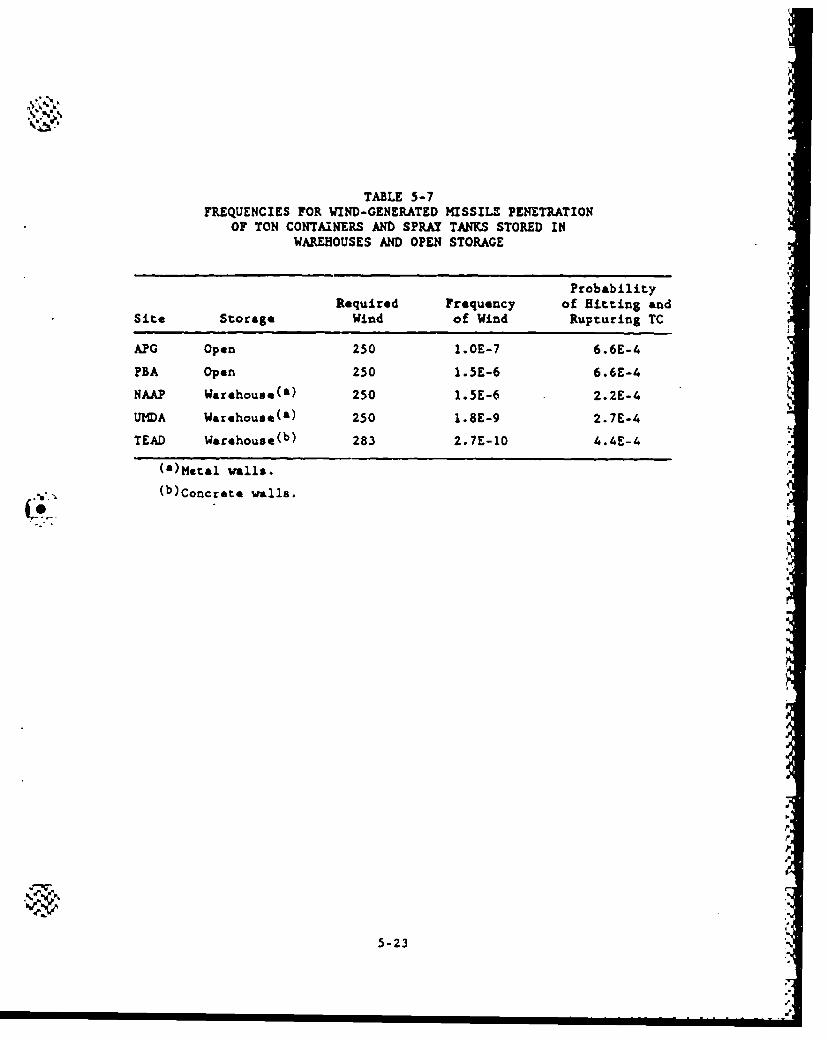
"S, %'
TABLE 5-7FREQUENCIES FOR WIND-GENERATED MISSILEr PENETRATION
OF TON CONTAINERS AND SPRAY TANKS STORED INWAREHOUSES AND OPEN STORAGE
ProbabilityRequired Frequency of Hitting and
Site Storage Wind of Wind Rupturing TC
APG Open 250 1.OE-7 6.6E-4
PBA Open 250 1.5E-6 6.6E-4
NAAP Warehous*(a) 250 1.5E-6 2.2E-4
UMDA Warehouse(e) 250 1.8E-9 2.7E-4
TEAD Warehouse(b) 283 2.7E-10 4.4E-4
(&)Metal wells.(b)Concrete walls.
5-23
/
probability of a missile hitting a ton container in an orientation which
could breach the container is 6.6 x 10⁻⁴ (see Appendix C).
5.2.1.4. Tornado-Gnerated Missiles Cause Munition Detonation. The
analysis of scenario SL23 included the estimation of the probability
that a missile impacting a nxiition wuld cause it to detonate or in
the case of rockets, cause the rocket motor to ignite and subsequently
detonate the burster. The data presented in Ref. 5-5 indicated that
a projectile with Comp B explosive could ignite when subjected to a
minim-m impact velocity of 123 mph. Because the conditions of the
tests described in Ref. 5-5 do not fully apply to the conditions being
considered here (i.e., the shell casing provides protection for the
bursters), it is assumed that there is a 50% chance that a m.,nition will
detonate at 123 mph. Furthermore, Army data indicate that dropping of
thousands of burstered munitions from 40 ft did not lead to any detona-
tions (Ref. 5-6). However, these are newer uinitions and may not fully
represent the chemical munitions in the stcckpile. Therefore, based on 'I'.
a consensus of risk experts (Ref. 5-19), an estimated failure proba-
bility of 10-6 per -munition drop was assigned to all drops of 6 ft or
lower (equivalent to a free fall drop of 13.5 mph).
To determine the probability of detonating a munition at an impact
velocity equivalent to that of a missile required to penetrate the iglooand the munition, we assumed a lognormal distribution and derived the p.
necessary parameters (e.g., standard deviation and standard normal devi-
ate) from these two data points. The calculation details are given in
the calculation sheets (Ref. 5-2).
The overall frequency for this scenario is the product of the
following:
1. The frequency of a tornado or wind which has sufficient veloc-
ity to generate a missile that can penetrate the igloo and
munition.
5-24
F
2. The probability of £ missile penetrating the igloo aud hitting
the munition in such a way as to cause damage.
3. The probability of bvriter detonation from impact.
The values for the first tw variables have already been presented
in Section 5.2.1.1. The probability of a detonation given penetration
of burstared -- nitions stored inside the igloos with steel doors is 0.07
and for concrete doors, 0.055. See Ref. 5-2 for calculations.
5.2.2. Meteorite Strikes
Like tornado-generated missiles, meteorites striking the igloos,
warehouses, and the outdoor yards can lead to a significant amount of
agent release. The consequence of such an accident is more severe than
that from a tornado-generated missile because meteorite strikes gen-
*rally involve fires. Hence, if burstered manitimns are involved,
explosive detonations could occur from the fire or from direct impact,
leading to iritantaneous agent releases.
The event tree developed for meteorite-initiated accidents is shown
in Fig. 5-2. The scenarios could not be subjected to any preliminary
screening without doing a more detailed analysis of the what type (stone
or iron) and size of meteorite is capable of penetrating munitions
stored igloos, warehouses, or outdoors. The only identified accident
sequence is SL8.
Storage Maxazines
In this scenario the meteorite penetrates the storage magazine and
ruptures some of the mnitions stored inside. The meteorite is expected
to be sufficiently hot to cause ignition of the exposed burster,
propellant, and/or agent. The fire is expected to spread, resulting in
the destruction of the entire inventory of the storage magazine.
5-25
L.W
Warehouses
This scenario is similar to the storage magazines. The meteorite
penetrates the warehouse and ruptures some of the bulk munitions stored
inside. The meteorite causes the ignition of the exposed agent. Fire
spreads and results in the destruction of the entire warehouse
inventory.
,Oen Storage
In this scenario, the meteorite directly impacts and ruptures some
ton containers. The heat from the meteorite is expected to ignite the
exposed agent, but is not expected to cause the rupture of additional-- ,nitions.[
5.2.2.1. Meteorite Strike Accident Analysis. About 3500 meteorites,
each weighing over 1 lb, strike the earth each year; the majority of .
them are of small sizes (Ref. 5-8). Given the earth's surface area of
5.48 x 1015 ft 2 , the frequency of meteorite strikes for meteorites
weighing 1.0 lb or greater is 6.4 x 10- 1 3 /ft 2 (Ref. 5-8). For meteor-
ites one ton or less, stone meteorites are approximately 10 times more
common than iron. However, iron meteorites are more dense and tend to
have higher impact velocities and therefore represent a significant
portion of the total meteorites that can rupture the munitions. Sac-
tion 4.2 presents the size distribution of both iron and stone meteor-
ites, compiled from data presented in Refs. 5-8 and 5-9.rI.
For agent to be released, the meteorite has to penetrate the stor-age structure and the muinition wall. In the case of an igloo, this
would require initial penetration of a 6-in. concrete roof. The minimum
meteorite impact velocity that would penetrate the earth cover and
collapse the 6-in. concrete roof is 1500 fps for stone mateorite and
5-26 1':
%
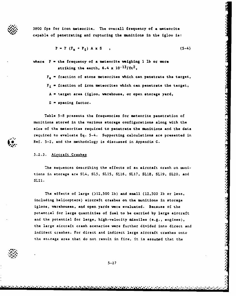
3800 fps for iron meteorite. The overall frequency of a meteorite
capable of penetrating and rupturing the munitions in the igloo is:
P - F (Fe + Fi) A x S , (5-4)
where F - the frequency of a meteorite weighing 1 lb or more
striking the earth, 6.4 x 10- 1 3 1ft 2 ,
Fs - fraction of stone meteorites which can penetrate the target,
Fi - fraction of iron meteorites which can penetrate the target,
A - target area (igloo, warehouse, or open storage yard,
S - spacing factor.
Table 5-8 presents the frequencies for meteorite penetration of
nmnitions stored in the various storage configurations along with the
size of the meteorites required to penetrate the -iitions and the data
required to evaluate Eq. 5-4. Supporting calculations are presented in5, -Ref. 5-2, and the methodology is discussed in Appendix C.
5.2.3. Aircraft Crashes
The sequences describing the effects of an aircraft crash on muni-
tions in storage are SL4, SLS, SL15, SL16, SL17, SL18, SL19, SL20, and
SL2l.
The effects of large (>12,500 lb) and small (12,500 lb or less,
including helicopters) aircraft crashes on the munitions in storage
igloos, warehouses, and open yards were evaluated. Because of the
potential for large quantities of fuel to be carried by large aircraft
and the potential for large, high-velocity missiles (e.g., engines),
the large aircraft crash scenarios were further divided into direct and
indirect crashes. For direct and indirect large aircraft crashes onto
the stcrage area that do not result in fire, it is assumed that the
5-27
%I
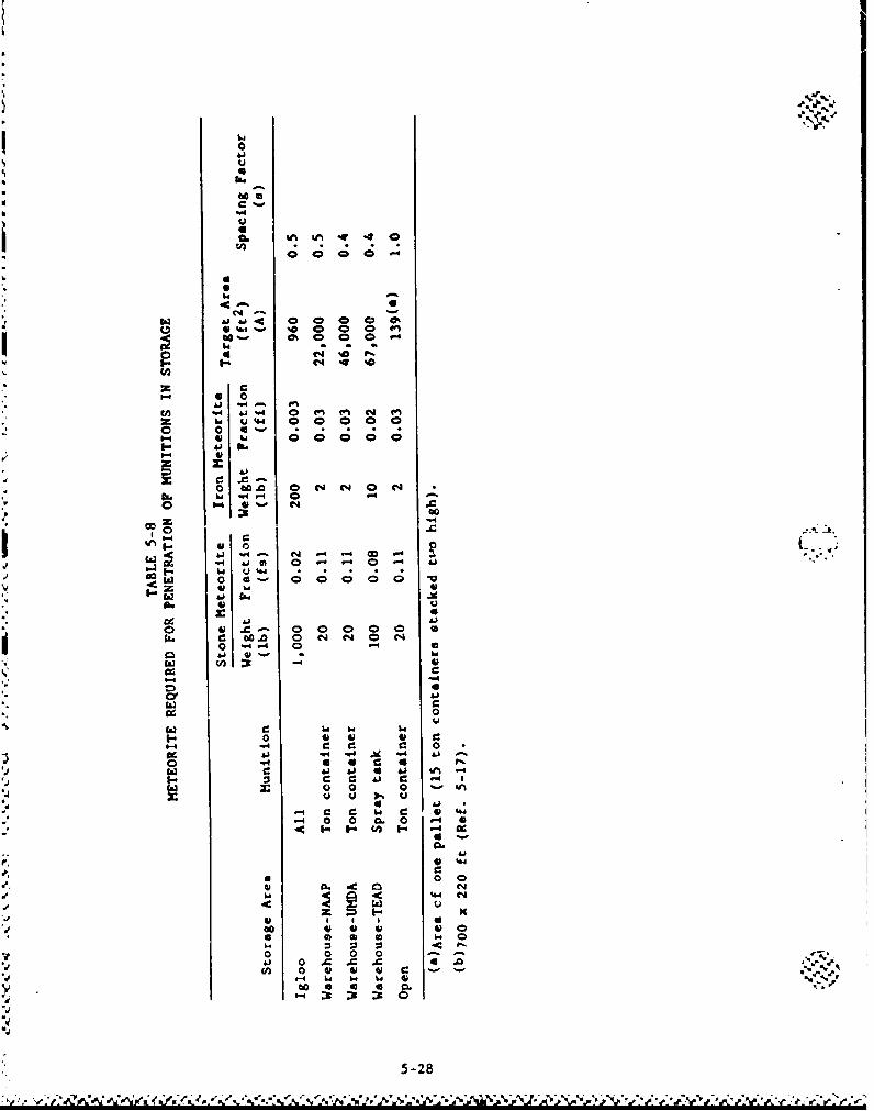
0 4
4.C4
0
N C X-
-. If 14 . 4%.o N
Li
0- 0
41 b
(41
o~ C.0 0-4 . -4 04 4
441
i1-4~ c4 c % -c 0
-4 0. 0 CL 0
I- ? 0 l 0
40 44 44 W
o 4£ 0 0 0 00 .9 0 X
'-4 -I
5-2
impact of the crash is strong enough to cause the detcnation of
burstered munitions.
For a small aircraft crash adjacent to the storage site to produce
a credible event, the crash would have to be so close that it would vir-
tually be a direct hit. Therefore, the small aircraft crash scenarios
address only direct hits into the storage areas including hnlding areas.
The event trees developed to identify the agent release vequences
from aircraft crashes are shown in Figs. 5-3 and 5-4.
5.2.3.1. Aircraft Crash Accident Analysiq. In savnary, the following
general assumptions were made in deriving the large/small aircraft acci-
dent scenarios:
1. For large aircraft crashes onto burstered mun 4tions, it is
assumed that detonations will occur for both indirect and
direct hits, and, if a fire occurs, it is uncontained.
2. No small aircraft crashes were assumed to be able to suffi-
ciently damage the igloo to cause agent releases.
Direct Crash of Large Aircraft (Sequences SL4. SL16. SLI7)/,
For a direct aircraft crash, the target area is the surface area of
the building or open yard,
Storage Maazines. The direct crash of the main body of a heavy
military or comnercial aircraft into the shell or front face of a stor-
age magazine ,igloo) can breach the igloo and allow crash-generated
missiles and/or aviation iuel to enter into the igloo. There is a high
probability that one or more muanitions will be crushed or punctured by
the missiles. Burstered munitions could also detonate from impact. If
tl~e crash produces a fire, the fire is expected to spread through the
igloo, resulting in the destruction of the ent're igloo inventory.
5-29
Ký Zý< .ýW PL 6. '".\,*"SA*ZA''ý1At''%" a.'A.. P_
%5
Warehouses. A warehouse is not expected to offer any substantial
resistance to crash of a large aircraft. The direct impact of any part
of a large aircraft will breach the warehouse and subject the stored
munitions to crash-generated missiles. Bulk containers will be crushed "'-
or punctured. If the crash produces a fire that it not contained, the 5'
destruction of the entire inventory is expected.
Open Storaze. The crash of a large aircraft into an open area ts
expected to breach a large number of ton containers. If the crash pro-
duces a fire, and it is not contained, it is expected to breach
additional containers in the immdiate vicinity of the initial container
that is on fire.
Indirect Crash of a Large Aircraft (Sequences SL5, SL20, SL21) .
For an indirect crash, the target area is determined by increasing .-.
all perimeters for the direct crash by 200 ft.
Storage Magazines. Should a large aircraft crash adjaeent to an %%
igloo, the area that is most vulnerable is the igloo door. The crash-
generated missiles can breach the igloo door which essentially provides
a pathway to the breaching of munitions in the line of site of the mis-
sile. Alternatively, the Igloo door may already be open at the time of
the crash and the missile could directly penetrate the munitions. If
fire is involved, the missile could already be on fire or the fire could
propagate into the igloo opening. Thus, if fire is not contained, the I
amount of agent release is the same as for the direct crash of a large
aircraft into an igloo.
Warehouses. The designs of the warehouses ace such that the crash
of a large aircraft into an area adjacent to a warehouse may also breach
the warehouse if tht aircraft is flying towards the warehouse at the
time of the crash. The amount of •unitions that are initially impacted -'
umuld be less than the direct crash scenario. However, if fire is
5-30
N.I
"involved and uncontained, the amount of agent release is the ame as
for the direct crash of large aircraft into a warehouse.
Open Storage. The accident scenario for the crash of & large air-
craft into an area adjacent to the open storage area considers that -
there is a 50% chance that some ton container* would be breached by the
crash-generated missile. If fire is Involved and not contained, addi-
tional containers would rupture aue to excessive heating.
Direct Crash of a Small Aircraft (Sequences SLUS, SLl8, SL19) i
Storage Maxazines. Due to the high strength of the storage maga-
zine, the crash of a small aircraft is not expected to breach an igloo
or affect the structural integrity of an igloo.
Warehouses. The crash of a small aircraft into a warehouse would
very likely breach the warehouse. The resulting crash-generated mis-
sils are expected to crush or puncture som* mnitions. If the crash
"produces a fire and it is not contained, the fire would involve the
entire inventory.
Open Storage. The crash of a small aircraft into an open storage
area is similar t,; the larga aircraft crash into an open storage area
except a smaller number of ton containers is breached.
5.2.3.2. Aircraft Crash Frequency. The frequency of an airt raft crish-
.ng while in an airway or in the vicinity oi an airport can be computed
as shown in Section 4.2.1.3. IThe annual frequency of a crash into a specific facility was com-
puted by multiplying the alpropriate frequency taken from Table 4-13 by
the effective target aLea of the facility (see Appendix C). Table 5-9
sumnnarizes these annual frequencies. The calculations of the effective
5-31
.5%w.~K Ž,:..:Jz.> 1 .5'-~ rC..~.~d~y ~ %%W..~\&/'f 5% 'V.,
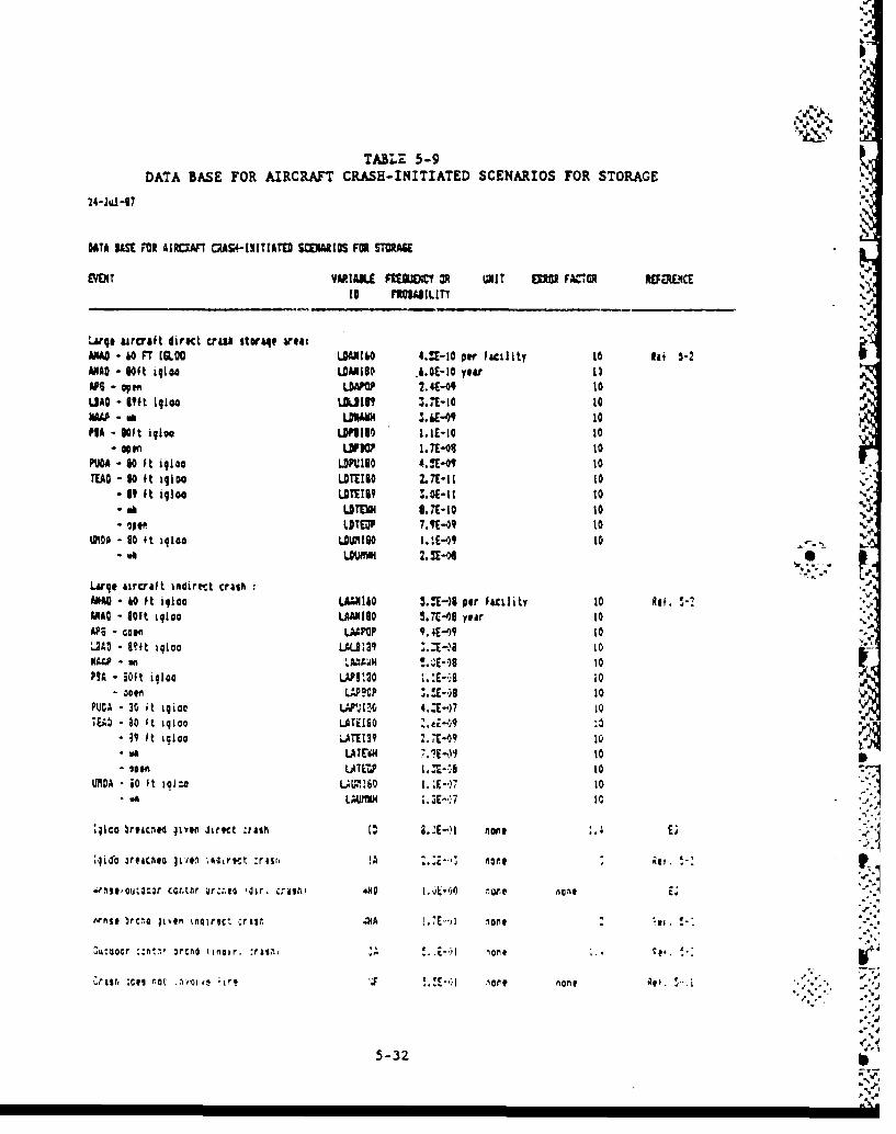
TABLZ 5-9DATA BASE FOR AIRCRAFT CRASH-INITIATED SCENARIOS FOR STORAGE
24-Jul -07
DATA 1*51 F02 AIRCAFT MA5I-1u1TIATO SCVIAIIS FOR STURA8E
VDT MULL PIUUCIW V L3nT! EUMO FAV OR RUMRE1CtD 1104lLItY
Large aircraft direct cras* itoaqe weaiMAO - 40 FT (CLOG UA1.310 4.11-10 per facility to Ili 5-2MAD - 60ft iqioo UAMISO .4.0E-10 year 0
APS- oen DAP 2.4-09 10LMO - 11ft iglooa Loie? 11.13-10 10 PMA -mwe LIMI4w 1.61-09 10PIA - 1N~t igloo un~iso ldIt-10 t0o1
. Oen O? 1. 7E-0I 10P1104 - 60 ft igloo LOPUIUO0 4.iQE-0" toTEAD -S 10t igloo LOTEIDO Lit-11 to
- i9 ft igloo LOTEIU .E-1 10. OE-"SSt*UTEMN l.7E-10 to
q* t LITEP 7.9(409 10(MO 00 t 19140 ULMI90 1.!E-"9 1to..
Largqe aircraft intdirect crash 5
ANMO 40 fot igloo LAM.N1&0 5.U-)e per facility 10 Alf. 5MMDC - loft igloo LAAM 100 5.X-00 year 10AP; Colo LM~p t. ,4E-" 10L240 - left igloo LUa .- a1NWA - anLAWNd toE~S1PIA -soft iuloo LAPI!20 1.1:-As t0
00 WOP ý.!E-*uS 10PUCA - 30 it Igicoor I N1~ 4..E-)7 1015- ao st igloo LATE160 .0i-'
- 39 It igloo S.ATUP! 7.1-09 10* aLATEMI 10.* Et- 254 LALW 1_1-_1 10
LMOA 0iO t io1.o LAWMiS 1..~E*)7 to
;l1co ýfIC.8 41yon J~fqI :fishi name- E;
:qi~f jr~icnoIviO l ;4ai~rmt :riut Ma2E'~ ngn
Arms* )rcno liven imairec, *rain .aIA l.E, one -
Z%4ttocr ::n~ir 3reno (inoir. :fait, .- KI on S4
fol.0# -..t'ue l -lore none Av.:
5-32
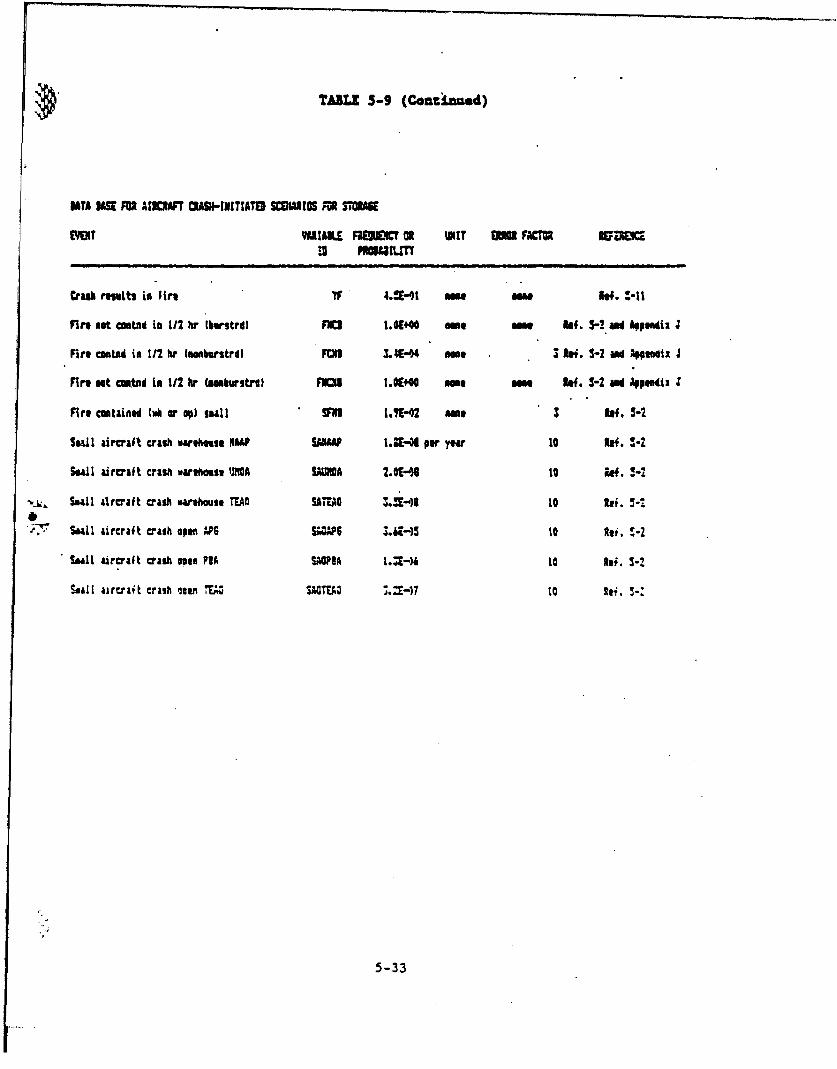
TABLE 5-9 (Continued)
DATA MWl P0M M3CR*T OASN-NITATO SCUIIRCS MP03SOOA
EYOT WAIAILE3 PIMU&I OR UNT UM FA Ra
Ciasi resvits in fire I .4 me Mae 3e.4I. -1
Fire not cuataid in 112 hr lberstrd) FICR 1.0640 me me Ref. 5-? &ai 41111"i: 4
Fire asntad in t12 hr (uubtustrd) FUlD 3.444 me 3 3ei. 1-2 and Appedix 4
Fire met cwutd in 112 hr (aesbvtarstr ROD 1.06440 moo me 1.4. 3-2 aid Appendiz
fire contained Cu or op) seall VNI 1.S-'2 me 3 f. 5-2
Small aircraft crash warthaise NAAP sawII U.E-M per yea to Rbf. N-
S.&11 aircraft crash varehouse UiIOA SDIA 2.0"S 0 to W. M
Sealla aircraft crash warhouse TEAfl SAMAG Z.N')D 0Re.
S Lll aircraft crash open APS SwSP 3.4E-4 10 Ati. !-2
Will aircraft crash onef PIA SAOPA L.3E-) to Rai. 3-2
Saall airtrait crash own 14 toEA lE~ ei.3
5-33
areas are contained in Ref. 5-2 and take into account such factors as •
aircraft wing span, facility height, and facility vulnerability. 1
5.2.3.3. Probability of Fire Resulting From an Aircraft Crash. The
probability of a fire resulting from the crash has been estimated to
be 0.45 (Ref. 5-12). The successful containment of the fire is defined
here to be 0.5 h for unpackaged nonburatered munitions. This time was
selected based on the thermal failure threshold data presented in Appen-
dix F, which indicate that direct heating of ton containers for 36 min
leads to hydraulic rupture. For unpackaged burstered munitions, the
thermal failure threshold range from 4 min for rockets to 23 min for
mines. Since the Army policy is not to fight a fire involving direct
heating of bursterod manitions, the probability of the "failure to
contain fire" event is essentially 1.0.
Thus, the amunt of agent released from bulk containers subjected
to aircraft crash fires depends on the ability to contain the fire. If
fire is allowed to progress for more than 30 min, more containers will a
rupture.
The ability of the fire-fighting team to extinguish an aircraft
crash fire depends on many variables such as the precise crash site, the
burn time of the resulting fire, the availability of resources necessary
to contain the fire, etc. If fire fighters arrive at the crash site in
a relatively short period of time, the fire will be easier to extinguish
since it is not likely to have spread very far. Because the fire will 0
involve chemical agent, additional precautions will have be taken before
the fire-fighting team can start extinguishing the fire. Their arrival
at the perimeter of the ?DB or 1HI is assumed to occur about 5 min after
the crash. The crew will have to put on agent protective clothing in
addition to their normal, fire-fighting suits of thermal protective
clothing. Donning these clothes and checking for proper mask fit would
take several more minutes, if it is assumed that the crew was partially
5-34A
dressed; i.e., in a standby readiness mode. Because of all the detec-D ) .
tion, observation, comuznication, preparation, and travel tasks
involved, it is estimated that it would take the fire-fighting team
15 min to get to the scene of the fire.
Once at the scene, the tim it takes to actually extinguish the
fire is difficult to estimate. GA interviewed local fire fighting per-
sonnel to get their opinion on how long it takes to extinguish a fire
from a small aircraft crash versus large aircraft crash. No definite
time can be given because of the many variables involved. But based on
local experience, it would take 1 to 3 h to extinguish a fire from a
small aircraft; while it would take 3 to 10 h for a large aircraft fire.
Using the lognormal distribution, GA than derived the probability of
containing the fire in 0.5 h or less and took no credit for the first
15 min of the fire. More details are provided in the calculation sheets
(Ref. 5-2).A,
~j.5.2.4. Earthquakes
5.2.4.1. Storage Magazine%. The earthquake-initiated accident affect-
ing the storage igloos assumes that the earthquake causes the Munitions
in the igloo to fall and be punctured given the presence of a probe on
the igloo floor or the fall could cause a burstered munition to detonate
(Sequence SL7). This scenario is modeled using the event tree illus-
trated in Fig. 5-5.
The storage magazines are expected to survive the largest credible
earthquake with little or no damage. Some cracking or spalling of the
concrete is possible, but this should not produce a threat to the muni-
tions or significantly change the containment capability of the mags-
zine. Igloos have been tested by very large external explosions and
have survived without damage (Ref. 5-11). The data from these testsindicate that the igloo experienced accelerations which were in excess
of 20 g. Though an explosion is not as potentially damaging to an igloo r
~ -V
5.-
II
4.
as an earthquake of equal acceleration, the similarities are sufficient e %.
to conclude that a very large earthquake, in the range of 1.0 g, is not
likely to damage an igloo.
Sequence SLU postulates that the earthquake causes the stacked
-nmitions to fall and may be punctured upon impact. Based or. the coef-
ficient of friction between pallets of munitions, & 0.3-g earthquake
will likely cause some stacked munitions to fall and a 0.5-g earthquake
will cause a large number to fall. The highest stacked munitions in an
igloo can potentially fall 6 ft. The manition failure threshold data
indicate that all palletized munitions and bulk containers can survive
the impact of a drop from this height but could be punctured if they
were to land on a probe which was sufficiently sharp and rigid. For
this analysis a 0.3-g earthquake was assumed to cause 25% of the stacked
pallets to fall while a 0.5-g earthquake will cause 100% of the stacked
pallets to fall. The numbar of pallets which have the potential of
impacting a probe was estimated for each manition type based on (1) how
the pallets are stacked and (2) the floor area available for the pallets @0to fall. The calculation details are provided in Ref. 5-2. "
The analysis of the presence of a probe in the igloo has indicated
that it is unlikely that there is a probe inside the igloo that is suf-
ficiently rigid and sharp to damage a uanition. Table 5-10 provides the
earthquake frequency data for each of the eight sites and the puncture
probability oi a munition type given a 6-ft drop.
Sequence SLZ2 involves the detonation of burstered munitions a
resulting from an earthquake-induced fall. The probability of a muni-
tion detonating from a 6-ft drop is estimated using the same approach
discussed for detonations due to impact by wind-generated missiles.
.-4
5.2.4.2. Warehouses. The event tree describing release scenarios
resulting from earthquake-induced accidents in warehouses is shown in
Fig. 5-6. The event tree applies to the long-term storage warehouses at
5-36
W.-M
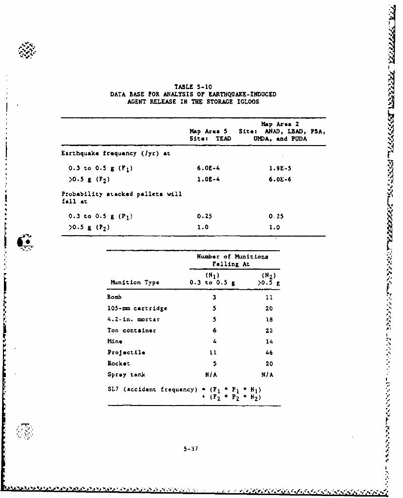
% %r
TABLE 5-10DATA BASE FOR ANALYSIS OF EARTHQUAKE-INDUCED
AGENT RELEASE IN THE STORAGE IGLOOS
Map Area 2Map Area 5 Sites ANAD, LBAD, PBA,Site: TEAD UMDA, and PUDA
Earthquake frequency (lyr) at
0.3 to 0.5 g (FI) 6.OE-4 1.9E-5
>0.5 £ (F 2 ) 1.05-4 6.OE-6
Probability stacked pallets willfall at
0.3 to 0.5 g (Pl) 0.25 0.25
>0.5 a (PZ) 1.0 1.0
Nu"mber of Munitions.' Falling At
(NJ) (N 2 )Munition Type 0.3 to 0.5 g >0.5 z
Bomb 3 11
105-rn cartridge 5 204.2-in. mortz--. 5 18 ;rTon container 6 22 •
Mine 4 14 "
Proj ectile 11 46 .
Rocket 5 20
Spray tank N/A N/A
SL7 (accident frequency) - (F 1 * PI * NJ)4- (F 2 * P2 * N2 ) /
"d
V. ' .•°
5-37 •
S.I,
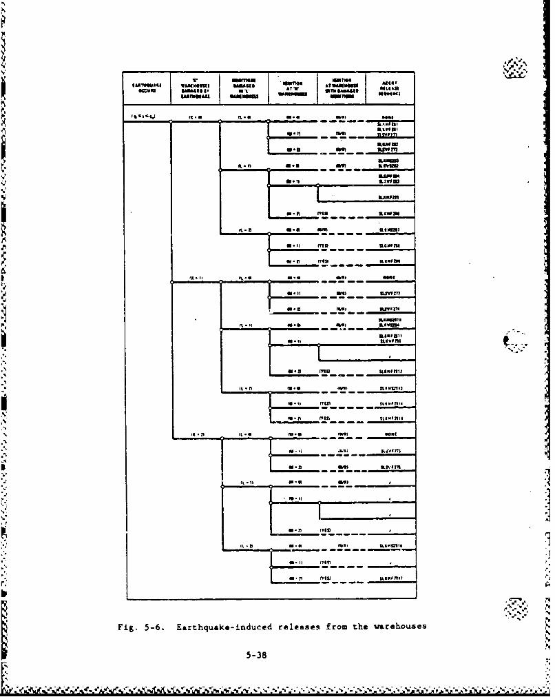
I*WWWII IT
I* -a - MR "ofKU
I *.,, atWMu
0.8 ftw Tn
IaMOU.4 arf=I
SAMOA
5.11 ~ yf ftU911011
ja - I I1*SG 0 - -ve 41"1a_____" -'
- 4 " 1 mI IIIm
WILI
Fi.56.Erhqaeinue re~leae from the i.IMhu-s
'U ~5-38
TEAD, NAAP, and UMDA. Spray tanks are stored at the two warehouses at
TEAD. Ton containers are stored at NAAP in one warehouse and at UMDA in
two adjacent warehouses.
Accident sequences describing releases from long-term storage ware-
houses are given in Table 5-11. Sequence designations are SLxzx26x for
the NAAP warehouse, SLxxx27x for the TEAD warehouses, and SLzzx28x for
the warehouses at U)DA. The accident sequence designations are also
shown on the event tree in Fig. 5-6. For those accident sequences where
no agent release occurs, the release sequence is labeled 'None." Those
release sequences whose frequency is below 1.0 x 10⁻¹⁰ for all sites
have been labeled with an "F" in the event tree. The events modeled in
Fig. 5-6 are discussed below:
1. Earthquake Occurs. The initiating event (Event 1) in Fig. 5-6
is earthquake occurrence. To simplify the event tree evalua-
tion, Event 1 further restricts the earthquake intensity to
an acceleration range from gl (0.15 to 0.2 g) to g. (7.7 g).
Seven ranges are consideredt p
a. 0.15 to 0.2 g.
b. 0.2 to 0.3 g.
c. 0.3 to 0.4 g.
d. 0.4 to 0.5 g.
e. 0.5 to 0.6 g. _
f. 0.6 to 0.7 g. L
g. Greater than 0.7 g.
Earthquakes below 0.15 g are not considered in the analysis
because the damage probabilities associated with such tremors
are negligibly small. Detailed examination of seismic ranges
above 0.7 g is unnecessary because earthquakes above 0.7 g
have a probability of almost 1.0 of causing damage.
r
5-39 •
I.>
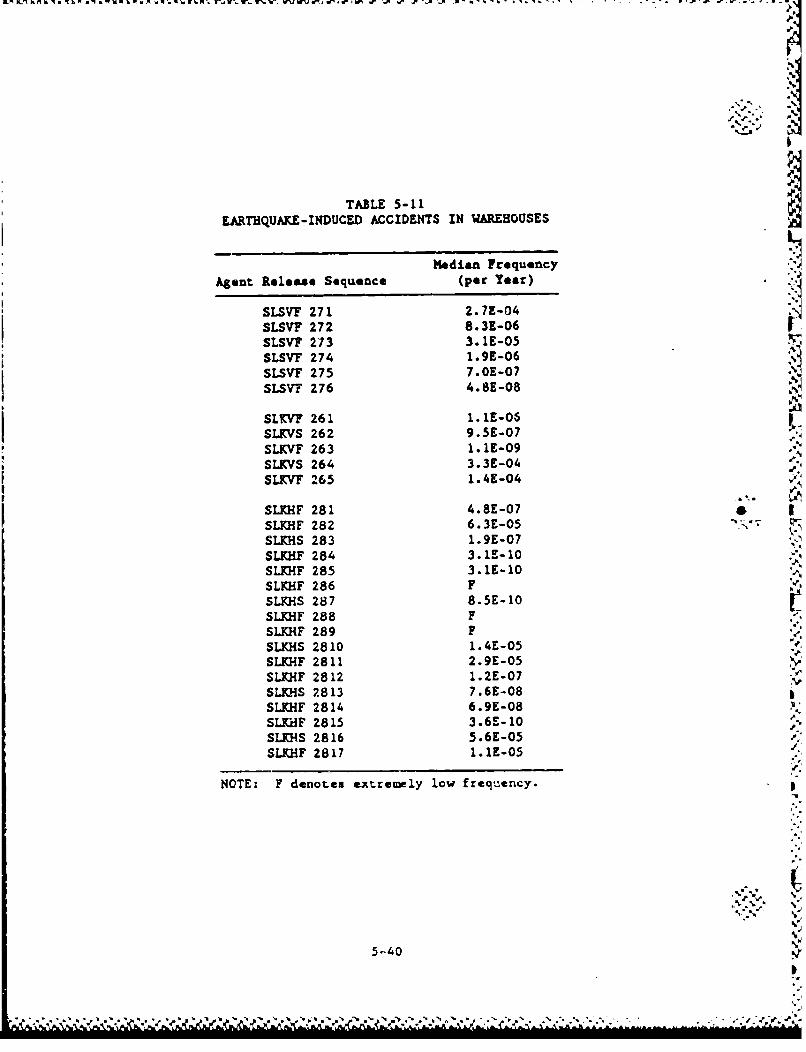
KýLIKAL -hýa - .1, , ý -. VW 'J b WJ .W -~~ W 1' - .P P . . . .' .
TABLE 5-11EARTHQUAKE-INDUCED ACCIDENTS IN WAREHOUSES
Median Frequency
Agent Release Sequence (per Year)
SLSVF 271 2.7E-04SLSVF 272 8.3E-06SLSVF 273 3.IE-05SLSVF 274 1.9E-06SLSVF 275 7.0E-07SLSV'F 276 4.8E-08
SLW'VF 261 1.•1E-06
SLKVS 262 9.5E-07SLKVF 263 1.1E-09SLKVS 264 3.3E-04SLKVF 265 1.4E-04
SLKHF 281 4.8E-07 •SLKHF 282 6.3E-05 'SLKHS 283 1.9E-07SLKIF 284 3.1E-10SLKHF 285 3.1E-10SLKHF 286 FSLKHS 287 8.5E-10SLKHF 288 F
SLKHF 289 FSLKHS 2810 1.4E-05SLKXF 2811 2.9E-05SLE.KF 2812 1.2E-07SLKHS 2813 7.6E-08SLKHF 2814 6.9E-08SLrdF 2815 3.6E-10SLKHS 2816 5.6E-05SLKHF 2817 1.1E-05
NOTE: F denotes ex.tremely low freqtuency.
5.40
5.-40 N
The initiating event frequency at each site is the site-
specific frequency at which earthquakes in the range gl to
gu occur.
2. "Ku Warehouses Damaged by Earthquake. Warehouse damage is
defined as structural collapse. This is the only failure
mode of interest because it will crush stored ton containers.
Although less severe damage can result from an earthquake, it
was screened in quantifying the Event 2 probability because it
does not induce ton container failure.
Three damage combinations are considered in Event 2:
a. No warehouses are damaged (K - 0).
b. Only one warehouse is damaged (K - I).
c. Beth warehouses are damaged (K a 2).
"Tracking these three probabilities is necessary in order to
"estimate the agent release source term. Note that since there
is only one warehouse at NAAP, the probability that K - 2 is
zero for that site.
Event 2 damage probabilities are based upon a generic study of
damage to structures designed to the Uniform Building Code.
3. Munitions Damaged in *L" Warehouses. Event 3 addresses
whether the earthquake causes an agent release from the stored
munitions. Two failure modes are analyzed: puncture and
crushing.
Only ton containers are subject to these failures. Spray
tanks are in overpacks which protect them from crush forces.
Furthermore, they are not stacked while in storage, hence they
cannot be punctured.
5-41
~ -*4 .~4**~./.* . p %
Throe damage combinations are considered in Event 3:
a. bo agent releases result from the earthquake (L - 0).
b. The earthquake causes an agent release in one warehouse
(L - 1).
C. The earthquake causes an agent release in both warehouses
(L - 2).
The puncture probability is the probability that at least one
ton container falls and strikes a probe of sufficient size and
density to penetrate it. The probability that ton containers
are crushed is correlated to warehouse damage. If K is 0, 1,
or 2 in Event 2, then ton containers in none, 1, or 2 ware-
houses are crushed, respectively. Since the NAAP site has on-
ly one warehouse, the probability that L - 2 is zero for that
site. In addition, since only spray tanks are stored in the
TEAD warehouses, L can only be zero at that site.
4. Ignition at "M" Warehouses. Seismically initiated fires are
an important consideration because they influence agent dis-
persion and can thermally fail agent containers. This second
aspect is particularly important at TEAD because fire damage
is the only spray tank container failure mode.
Electrical fires are the only concern in warehouses. The
three conditions necessary for an electrical fire are:
a. An electrical fault capable of causing arcing.
b. A supply of electric power to sustain the arc.
c. Contact with an ignition source.
5.5-42
• • m a o-.................... o. ......•/ • "•","• ¢"" •".', .' '."'", '•",". '•;2 " " " 2. "' / -". -. " . ..- ". - ",", . .- • : :..". " ."- - .- .- , . .
%
Including this second condition in the fire ignition probe-bility calculation is important because available data indi-
cate that offsite power can be lost at a relatively low
seismic intensity.
Condition three considers both the agent and wood dunnage
assemblies as possible ignition sources in the warehot-eao. If
ton containers have been damaged by either crush or puncture,
the probability of igniting spilled agent given an electrical
arc has occurred is essentially unity. If no uanition damage
has occurred, the probability of igni•tion is represented as
the ratio of exposed wood surface area to the total area of
the warehouse.
a
Similar to previous events, Event 4 addresses how many ware-
houses experience ignition.
5. Ignition at Warehouse With Damaged Munitions. If the earth-
quake only damages the containers stored in one warehouse and
ignition occurs at only one warehouse, it is necessary to dis-
cern whether the fire is in the warehouse with the damaged
containers. If the fire is in the same warehouse as the dam-
aged containers, thermal failure and the subsequent release of
agent from the second warehouse is averted. However, if the
damaged containers and fire are in different waereouses, then
the agent release source term will be increased.
Suppression of fires has a negligiblc probability since the
warehouses have no fire alarms nor automatic fire suppression
systems. For this reason it is not considered in the
warehouse analysis.
5-43
::I
5.2.5. Lithtnins i%
Munitions stored iu igloos and warehouses are protected from light-
ning. Hence, only ton containers stored outdoors at APG, PBA, and TEAD
may be susceptible to lightning strikes. No event tree model h.s been S
developed for this scenario. Basically, if sufficiently energezic
lightning strikes a ton container, the container will be breached and 9
agent will spill to the ground.
A lightning strike density for the contiguous United States was
previously determined (Ref. 5-12) based on the correlation developed
from the duration of thunderstorms. 3ased on this empirical correla-
tion, the frequency (events/yr-km2) for the different storage locations
has been determined, as show-A in Table 4-7.
Using conservative assumptions, a threshold lightning energy
required to burn through the ton container wall was found to be propor-
tional to the fourth power of the wall thickness as described in the
calculation sheets (Ref. 5-2). Neglecting corrosion thinning of the 71
container wall, the maximum value of failure frequency for each cluster
of 15 ton containers at PBA is 5.1 x I0-10, as shown in Table 5-12.
The results indicate that the threshold lightning energy required
to burn through the container wall is a strong function of wall thick-
ness. In order to assess the sensitivity of the failure frequency to
corrosion, a probability density function for wall thickness was derived
by conservativtly assuming that one ton container stored outdoors has a
leak through its wall. This is a conservative asesuption since no wall
leak has been reported. This probwLility density function for wall
thickness is used in conj'inction with the lightning energy requi.rements
to calculate the failure frequency of a clu-ter of 21 containers at the
different sites. As expecttd for the PBA site, the failure proba~ility
is increased by upprcximately 55 from the prev4 .ous value ot 5.1 -c 10-10.
44.
% %'
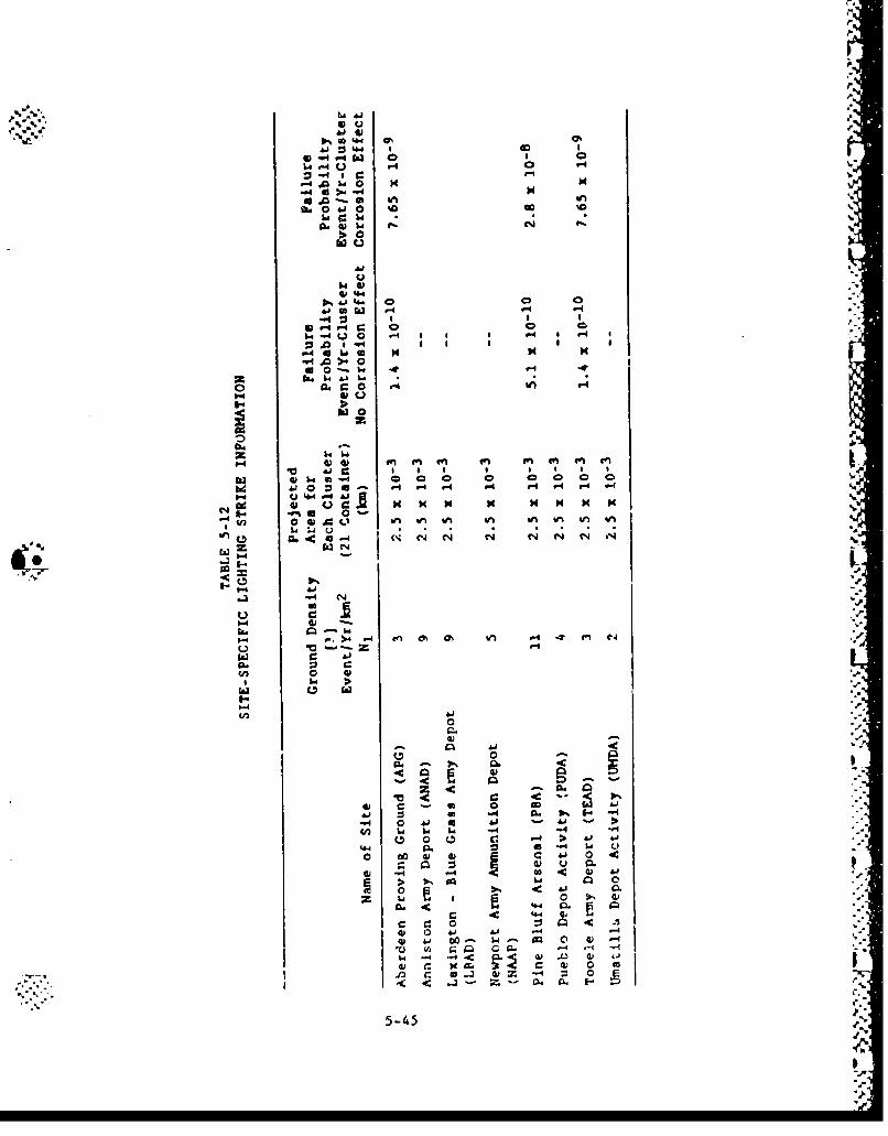
4)4
41 @1
P-4V-4b 0 0
0 -1
4. -4 &
tm tn i
0.4, Al. 4cN 1, N
IF..
-4 J C-4 -4 -
1-4 4U .-4 fn 4m kn -
-4-4 ~
21 a1.eJ&
a4 - 1 64" 0 0 a w L
-~c 4,, 4l ' 4 01 4 04 <~ w
4, ~ ~ LOA 0 000
"'000, 41 &J I-
5.4 <J (L 4
a.~ r4 a. Cl W1 A -4 t 01
lo C6 I
4-5-45
NZ-
If all other agent releane scenarios have frequencies that are-,
below this bounding vp 1 .ue, then the extent of container corrosion mast 1
be investigated. However, if other scenarios involving comparable or
larger amounts of agent rsleass also have much higher frequencies than
the bounding value for the lightning initiated release, then lightning
release scenarios can be ignored. ""his is true for aircraft crash acci-
deuts which lead to roac larger releases and also higher frequencies for
some *ites,
5.2.6. !loods
During a flood, materials such as lumber, crates, storage tanks,
and other lightweight containers may be carried away by flood flows and
cause damage tc downstream structures. Water velocities during floods
depend largely on the size end shape of the cross sections, conditions
of the stream, and the slope had, all of which vary on different streams
and at different locations. In the upper reaches of a flood basin, main
channel flows could be as high as 14 ftIs, but typical overbank flow is •
less than 2 ft/s (Ref. 5-13).
Munitions stored in igloos and warehouses are considered protected
ag•ainst flood-genetrated projectiles. The only uanition stored outdoors
are nmustard-filled ton containers (APG, PBA, and TEAD). %.
The puncture equttiGn is as follows:-.9
Vm- {64 (672 DT) 3 / 2 )/W
where D - probe diameter (in.),
T * wall thickness to be punctured (in.),
W - weight of projectile (i.e., moving object) (lb),
VM- velocity of projectile ( 7t/s).
5--
5-46 ' -
S,-,•-
The wall thickness of the ton container is 0.41 in. Assuming the
smallest probe size is 0.8-in. in diameter,
V2 (W) - (64)(672 DT) 3 / 2 217,335 (5-6)
For puncture, the following conditions must be met:
Vm W •
(ft/s) (ib)
1 217,335
2 53,334
6 6,037
10 2,173
14 1,108
A credible flood-generated projectile is assumed to be a light,
steel tank- with a rigidly attached 0.8-in. diameter probe. This could
be a water storage tank or a gasoline tank, using a tank height to diem-
eter ratio of 1.2 and a wall thickness of 0.25 in. Table 5-13 presents
the data developed for steel tanks. Tanks larger than 10 ft in diamet-!r
would not be credible except in main channel flows. Thus, typical over-
bank flows, i.e., 2 ft/s, would not produce puncture.
Puncture could be initiated by using an extreme overbank velocity
of 6.13 ft/s combined with a 10-ft diameter floating tank with a rigidly
attached 0.8-in. probe. The probability of a 6.13 ft/s overbank veloc-
ity is estimated to be less than 10%. This condition will be designated
as the reference flood-gensrated projectile.
The probability of puucture of a single ton container from the
reference single floating tank condition is as follows: v.
PF Lp x Tp x Pp (5-7)
5-47
"el.
S•S.. . . . . . .. . . . . .. . . . . . . . . . . . 1 " 'T ' 'T ' 'I'T I "• "5
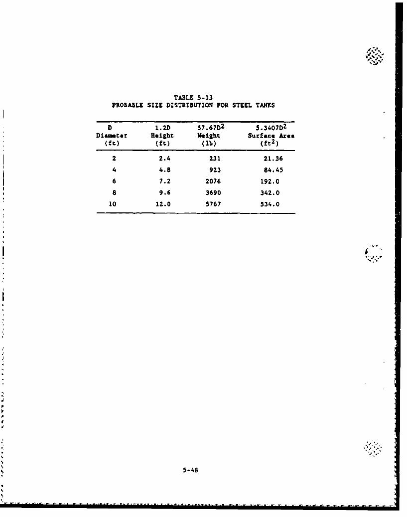
TABLE 5-13PROBABLE SIZE DISTRIBUTION FOR STEEL TANKS
D 1.2D 57.67D2 5.3407D2
Diameter Height Weight Surface Area(ft.) (ft.) (lb) (ft 2 )
2 2.4 231 21.36
4 4.8 923 84.45
6 7.2 2076 192.0
8 9.6 3690 342.0
10 12.0 5767 534.0
F..,
5-48
bl d.o
O,; where Lp w location probability, i.e., the probability that the probe
attached to the floating tank is pointing towards the ton
container wall at the munt of collision,
Tp - target probability, I.e., the probability that the tank
collides with the ton container,
Pp - probability of probe being present.
LP can be approximated by the ratio of total surface area to the
effective surface position. Assuming that the probe mcit be within a
1 ft 2 location, then:
Lp - 1/1(7.06)2 (5.3407) - 0.0038 . (5-8)
Tp can be approximated by assuming a flood channel width at the
point of collision and comparing that to the length of a ton container
"(82 in.). Using a three-mile wide channel, which is conservative for a"typical flood, then:
Tp - 82/((5280) (12) (3)) - 0.00043 or 0.0043 (5-9)
for the total width of 10 containers.
Pp is estimated to be I x 10-3. Thus the probability of a reoer-
ence tank hitting and rupturing a ton container is
PF - (0.0038) (0.0043) (0.001) - 1.6 x 10.8 (5-10)
It would seem reasonable from the flood basin size to assume no
more than one reference floating projectile per flood and the flood
reoccurrence to be greater than 100 years. In addition, the probability
of a 6 ft/s overbank velocity is estimated as 10%. Thus, thi probabil-
ity of rupture is approximately 1.63 x 10- 1 1 /yr.
5-49
WON
Thus, based on the above calculations this scenario can be screened
out on the basis of the frequency criterion of less than 1.0 x 10 1 0 /yr.
.I
N
.,_
.55
dA.
So..
iS.-
I
°S...
5-50 .•
'-,
.-J,-.F
wit-
5.3. SPECIAL HANDLING ACTIVITIES
5.3.1. Leaking Munitions
Several scenarios were identified that specifically address the
leakage of stored munitions and the accidents that could occur in the
process of isolating leaking mwaitions whith could aggravate the exist-
ing situation. The event tress are shown in Figs. 5-7 and 5-8.
Sequence SLI addresses the possibility that a n•nition could leak
from the time the periodic inspection has been performed until the next
periodic inspection. It is assumed that the leaking munition will be
detected at the time the next inspection is made. For all sites, except
at APG, the inspections are assumed to be performed quarterly (90 days).
At APG, the ton containers are inspected daily. No event tree was
developed for this scenario since it is represented by a single event
failure.
"Sequences SL2 and SL9 address accidents related to the movements
of munitions for inspection or isolation of leakers. The forklift tine
puncture or drop of munition was determined to be largely due to human
error. rhe quantification of these events required a detailed human
reliability study (Rpf. 5-14). Essentially a task analysis was per-
formed to identify those errors that could potentially impact agent
release probabilities. Available data was used to quantify the proba-
bilities of some of these errors and extrapolations were made from these
fixed data to quantify the remainder.
Isolation of leaking rockets require special tasks. The leaking
rockets are isolated in the storage igloo at the original location,
where the pallet containing the leaking rocket is unpacked. Only thoce
truck that will carry it to an igloo reserved for leaking munitions
(Ref. 5-1). The analysis assumes that the same procedure is followed
5-51
• i°• ¢ • , • r • • ,- . • . . . . . . . . . . . . .. . .
FORKLIFT TINE AGENTACCIDENT MUNITION RELEASE
(INSIDE IGLOO) INTEGRITY SEQUENCE
INTACT
PUNCTURED SLZ
I S._______________I______
Fig. 5-7 Munition punctured by forklift tine during leaker -handling activities
'.5
Is
U-'',
5s-5 2 VIA.5.
b
'I A -A.
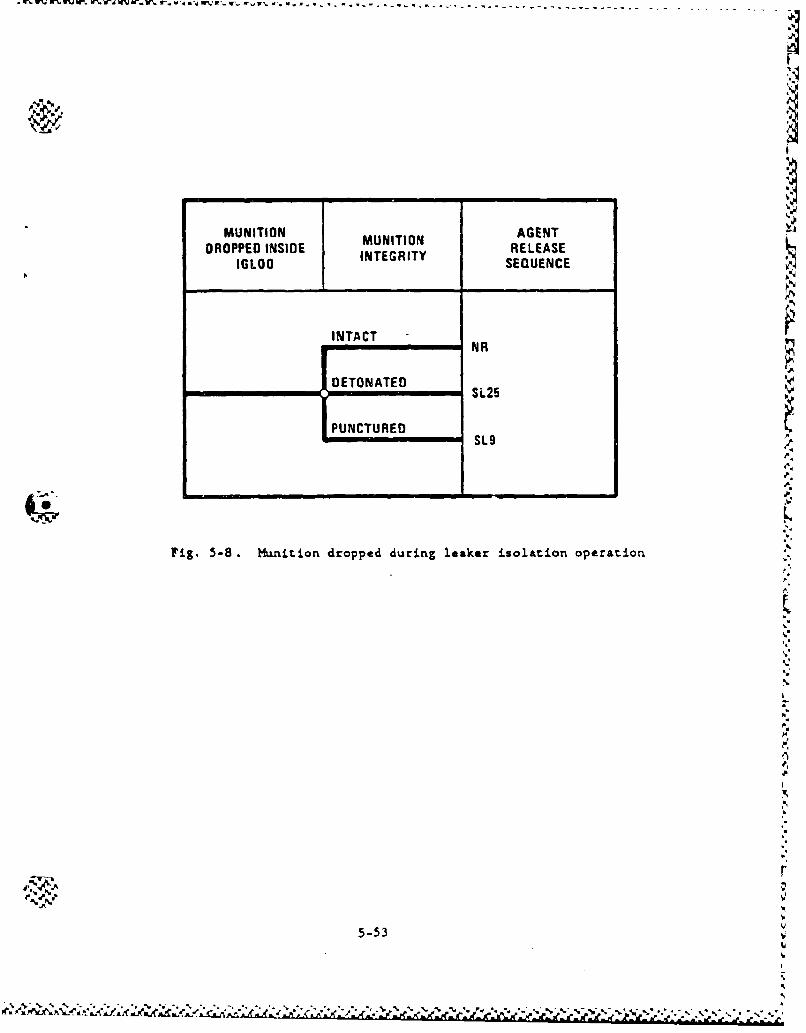
MUNITION AGENTM TI MUNITION
DROPPED INSIDE RELEASEI LC INTEGRITYIGLOO SEQUENCE
INTACTNR
IDETONATED S2S, SL25
PUNCTUREDSL9
Fig, 5-8. Munition dropped during leaker isolation operation
5-53 %1
'S
p.
p.
il
for isolating other leaking munitions, except that overpacks (other than V -%JbPIGs) are used.
Three types of operator errors related to leaker isolation wre
identified it. the task. analysis: (1) puncturing a munition with &
forklift tine, (2) dropping a munition or pallet from a forklift, and
(3) dropping & singie munition while hand-carrying it. These errors are
discussed in more detail below.
1. Puncturing a mnition with a forklift tine might occur any
time a munition or pallet is approached with a forklift tine.
Puncture probability is a function of the human error that
results in impact of the tine with the .unition and of the
vulnerability of the munition to such an impact.
2. Dropping a munition or a pallet from a forklift could occur
any time a forklift is carrying a load. This action could be
csued by operating the forklift in a way that causes the load
to fall or by loading the forklift such that the load is mis-
aligned or the weight distribution within the pallet or muni-
tion is unbalanced. It could also result from the pallet's
getting caught on and pulled off by something it runs into.
Sudden acceleration or deceleration, sharp turns, high-speed
operation, or operation over uneven ground could all be
contributors to munition drops.
3. Dropping a munition while hand-carrying it might occur any
time the munition is picked up, put down, or carried without a
forklift or other lifting device. It could be caused by theoperator's falling as he carries the -munition or by the muni- J
tion's slipping from his grasp.
A previously identified scenario involving the improper replacement
of a corroded valve or plug in a ton container (Sequence SLI6,
5-54
P
Ref. 5-15), has been deleted in the present evaluation. It is expected
that ton containers with GB will require that their valves be replaced
before 1991. The human reliability analysis (see Appendix J) concluded
that this event has a low frequency of occurrence. Furthermre, the
amount of mustard or 11X that cculd be dispersed to the atmosphere from a
valve or plug replacement operation is insignificant.
Table 5-14 presents the data used to evaluate the accident fre-
quencies for the scenarios addressed above. The frequency of scenario
SL1 was derived by determining the leakage rate for each munition type
based on the leaker data at each site and the total minition inventory
at each site. Sinte the tw paramters are classified information, they
wil be presented and discussed further in a classified appendix.
5.3.2. Human-Error Probability EstimatioaL
Th4 humanW error probabilities were quantified. Using the approach
to human-error estimation described in't1REG/CR-1278 (Ref. 5-19). Prob-
abilities of human errors were estimated based on several performance-
shaping factors such as munition configuration, handling operation,
clothing level, and crew size. These factors are identified in the
discussions that follow on the derivations of each estimate. Table 5-15
lists the error probabilities estimated for puncturing or dropping a
muni.ion based on each of these factors.
1. Puncturing a munition. The basis for the error estimates is
taken from Section 4.4.2 of Reference 5-1 (pps. 4.4-26). This
reference gives 4E-5 &a a data-bared estimate of the probabil-
ity of handling errors using forklifts for the rocket stock-
pile. This is an estimate of the likelihood of an error in
forklift operation that potentially could lead to a warhead
rupture while attempting to isolate a leaking rocket inside
the storage igloo.
5-55
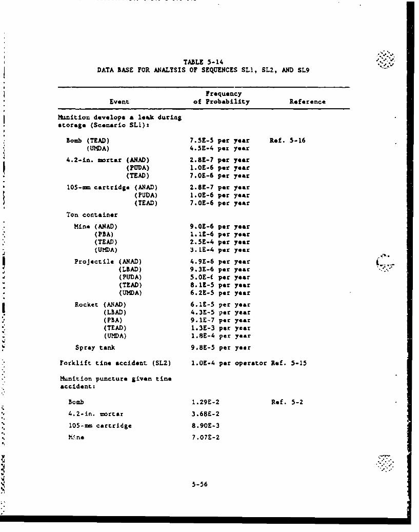
TABLE 5-14DATA BASE FOR ANALYSIS OF SEQUENCES SLI, SL2, AND SL9
FrequencyEvent of Probability Reference
Munition develops a leak during
storage (Scenario SL1)*
Bomb (TEAD) 7.5E-5 per year Rof. 5-16(UMDA) 4.5E-4 per year
4.2-in. mortar (ANAD) 2.8E-7 per year(PUDA) 1.OE-6 per year(TEAD) 7.OE-6 per year
105-rn cartridge (ANAD) 2.8E-7 per year(PUDA) 1.OE-6 per year(TEAD) 7.OE-6 per year
Ton container
Mine (ANAD) 9.OE-6 per year(PBA) l.1E-6 per year(TEAD) 2.5E-4 per year(U1DA) i.LE-4 per year
Projectile (ANAD) 4.9E-6 per year,(LBAD) 9.3E-6 par year ',
(PUDA) 5.0E-( per year(TEAD) 8.1E-5 per year
(UfDA) 6.2E-5 per year
Rocket (A.4AD) 6.1E-5 per year(LBAD) 4.3E-5 per year(PBA) 9.1E-7 per year(TEAD) 1.3E-3 per year(U11DA) 1.8E-4 per year
Spray tank 9.8E-5 per year
Forklift tine accident (SL2) 1.0E-4 per operator Ref. 5-15
Munition puncture given tineaccident:
Bomb 1.29E-2 Ref. 5-2
4.2-in. mortar 3.68E-2
105-rn cartridge 8.90E-3
%Wne 7.07E-2
5-56
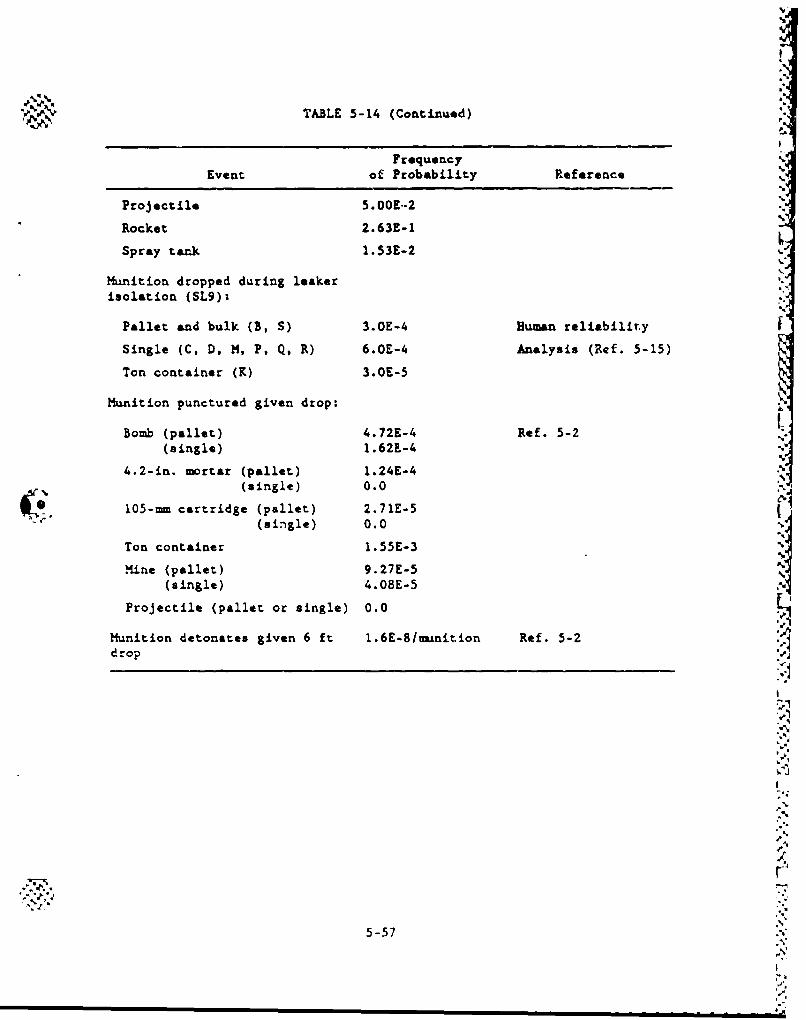
TABLE 5-1.4 (Continued)
FrequencyEvent of Probability Reference
Projectile 5.00E.-2
Rocket 2.63E-1
Spray tank 1.53E-2
Munition dropped during leakerisolation (SL9):
Pallet and bulk (B, S) 3.OE-4 Human reliability ISingle (C, D, M, P, Q, R) 6.OE-4 Analysis (Ref. 5-15)
Ton container (K) 3.OE-5
Munition punctured given drop:
Bomb (pallet) 4.72E-4 Ref. 5-2(single) 1.62L-4
4.2-in. mrtar (pallet) 1.24E-4(single) 0.0
105-mm cartridge (pallet) 2.71E-5"(single) 0.0
Ton container 1.55E-3 IiMine (pallet) 9.27E-5 %
(single) 4.08E-5
Projectile (pallet or single) 0.0
Munition detonates given 6 ft 1.6E-8/nuinition Ref. 5-2
drop
-55
'ft
5-57 .tf"
p..
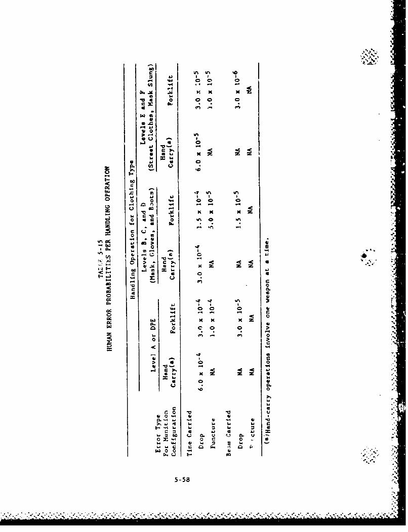
c X ftIft
v1 0
0 a 000
ma
0
4 0
> . 4 .V bw x
1-4
-4~~4 0, 4
(A -4-61 14 14 142 0
0 w ~ x
0 ".CL -4& 4 -4* 4)
oj to Ww w a
* 0 m -4w. 434- 4¶
0 4 w- C 4 4441~ 03i422
C .- 02 5-58.
,.. That estimate ia bated on "nditionos that do not entirely
represent those assumed by this study; namely, that & three-
man crew will perform all fork-lift orerationa. In this study,
it is assumd that a tw-msn crew will. ?erfurm all foxklift
operation---one drivirg the forklift and one guiding forklift
and munition position from the ground, This means that the
data-based estimate may not represenx the probability of
forklift-handling errors expected under actual conditions.
Therefore, this estimate was revised to 1 x 10⁻⁴ to account
for a smaller crew. The revised estimate of I x 10.4 is the
probability that Lnt or both members of a tw-man r-rew will
err such that the forklift tine is in a position to puncture a
munition. (This puncture probability applies to those cases
in which forklift tines are used to lift munitions; it
includes palletized munitions and spray tanks in overpacks.)
Another difference is that the original estimate from Refer-
j ence 5-1 (4 x 10⁻⁵) was based on operations with leaking rock-
--' • ets. This meant that it assumes that the crew is wearing
Level A protective clothing. If the same forklift operations
are periormed in less strenuous circumstences (i.e., if a
lower level of protective clothing is worn), the error proba-
bility estimate can be lowered. Here, it has been lowered to
5 x 10⁻⁵ for the case of the operators' wearing pa-tial pro-
tection (masks, gloves, and boots) and to 1 x 10⁻⁵ for the
case of their wearing minimal protection (street clothes, Vith
masks *lung).
2. Dropping a munition. For pslletized munitions and spray tanks
in their overpacks, huimn-caused drops from forklifts are
judged to be three t•.oes as likely as punctures caused by
operatinag the same kind of forklift. The error-probability
estiiates are 3 x 10-, 1.5 x 10- 5 , and 3 x 10- for dropping
5-59
a munition from a forklift tine when warLng Level A, Level C,
or Level F protective clothing, respectively.
Because of unwieldy pallet and overpacked spray tank loads and
because it is assumed that forklift-tine loads are likely to
be carried at higher speeds than are forklift-beam loads, the
likelihood of a TC's or other beam-carried load's being
dropped because of human error is judged to be an order of
magnitudt lower than that of a tine-carried load's being
dropped. These aro estimated to be 3 x 10⁻⁵, 1.5 X10- 6 ,
and 3 x 10⁻⁶ for protective clothing Levels A, C, and F,
respectively.
For hand-carrying ninitions, munition drops are estimated to
be twice as likely as drops of tine-carried loads from fork-
lifts. The estimated probabilities of dropping a hand-carried
munition when wearing Levels A, C, and F protective clothing
are 6 x i0-4, 3 x 10⁻⁴, and 6 x 10⁻⁵, respectively. (Load*
carried by forklift beam are never hand-carried.)
These probability estimates are the likelihood of an error per
handling operation. A single forklift operation may involve a
single munition such as a spray tank or as many as 48 weapons
on a Vallet, %hile a single hand-carry operation will always
involve only a single .znititri,
5.3.3. Surveillance and Maintenaned Activities
For the continued storage option, additional handling accident
scenarios were identified which relate to the planned a~rveillanLOe Und
maintenance of mnitinr&% over the 25-yr continued storage ptriod.
According to information provided to GA by the U.S. Army, all currently
stored munitions will be taken out of their present storage locationsz
and brought to a maintenance fa:ility for irspectlon. The rink an.y•ylp.
5-60
v_
addresses on. the accidents that could occur during the movement of
these m.nitioue Zrom storage to the maintenance facility and back to
storage. Table 5-16 shown the number of times each munition type will
be moved to the maintenance facility for surveillance. Note that not
all munition types are shown in thfs list. It is therefore assumed that
the handling and transportation accident scenarios will not apply to
those -- nitions not listed in Table 5-16. Table 5-17 Ulste the
handling-related sequences that ware identified. Sequences SHI through
SH7 involve surveillance and scenarios SH8 through SH12 involve pallet
inspection. For pallet inspection, the procedure is to move the pallet
to the igloo apron and imspect the pallet for any degradaticn visually.
It is assumed that only electric forklifts will be used to mvQ the
pallets.
The analysis of these activities does not include the actual main-
tenance performed on the individual munitions. It is not clear what
type of maintenance will be performed during this period. Furtheriore,
(." it may also be possible that the maintenance will be performed in-situ.
Although the number of handling activities considered the movement of
the munitions from their storage locations to a maintenance facility by
truck, the accidents involving actual onsite transportation were not
specifically analyzed. The results of the onsito transportation analy-.
sis for the Onsite Disposal Option (Ref. 5-19) are considered to apply
here.
It is not yet clear if the Army will move the munitions in over-
packs should it decide to choose the continued storage alternative. If
the Army decides to put them in overpacks then the transportation risk
analysis results for the onsite option directly apply. However, the
5-61
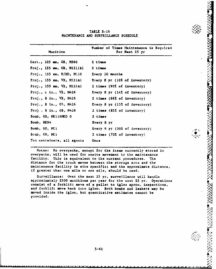
TASLE 5-16MAINTENANCE AND SURVEILLANCE SCHEDULE
Number of Times laintenance is Required N
H.nition For Next 25 yr
Cart., 105 m, GB, 14360 2 times -.
Proj., 155 m, GB, M121/Al 2 times9. m
Proj., 155 m, H/HD, M110 Every .10 months
Proj., 155 mm, VX, M121A1 Every 8 yr (102 of inventory) ."
Proj., 155 mm, VX, M12IAl 2 times (90% of inventory)
Proj., b in., VX, M426 Every 8 yr (14% of inventory)
Proj., 8 in., VX, M426 2 times (86% of inventory)
Proj., 8 in., G.1, M426 Every 8 yr (15% of Inventory)
Proj. 8 in., GB, 14426 2 times (851 of iuventory)
Bomb, GB, Ml116MD 0 2 times
Bomb, NK94 Every 8 yr
Bomb, GB, K-1 Every 8 yr (301 of inventory)
Biomb, GB, MCI 2 times (702 of inventory),.
Ten containers, all agents Once
Notes: No overpacks, except for the items currently stored inoverpacks, will be used for onsite movement to the maintenancefacility. This is equivalent to tht current procedures. Thedistance for the truck moves between the atorage aoro and themaintenance facility is site specific| end the approximate dis;tance,if greater than one mile or one mile, should be used. P
Surveillance: Over the next 25 yr. surveillance will handle 0-approximately 2500 •unitions per year for the next 25 yr. Operationsconsist of a forklift move of a pallet to igloo apron, inspections,and forklift move back Into igloo. Both bombs and leakers may bemoved inside the igloo, but quantitative estimates cannot bepzovided. •
5-6..2
* ..,.
5-62 •,
S.. .. ... .. . . .. .. .... . . ... ... . ... .. - . " " ',,. . . .. i . . ..... " ",.... " r'' d** " • ' '''
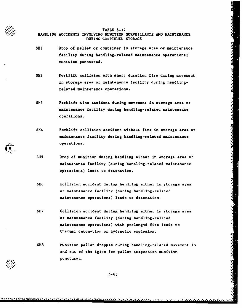
TABLE 5-17HANDLING ACCIDENTS INVOLVING MUNITION SURVEILLANCE AND MAINTENANCE
DURING CONTINUED STORAGE
SHi Drop of pallet or container in storage area or maintenance
facility during handling-related maintenance operations;
munition punctured.
SH2 Forklift collision with short duration fire during movement
in storage area or maintenance facility during handling-
related maintenance operations.
SH3 Forklift tine accident during movement in storage area or
maintenance facility during handling-related maintenance
operations.
SH4 Forklift collision accident without fire in storage area or
maintenance facility during handling-related maintenance
(4.1.operations.
SK5 Drop of sunition dutLing handling either in storage area or
maintenance facility (during handling-related maintenance
operations) leads to detonation.
SH6 Collision accident during handling either in storage area
or maintenance facility (during handling-celated
maintenance operations) leads to detonation.
SH7 Collision accident during handling either in storage area
or maintenance facility (during handling-reltt.ed
maintenance operations) with prolongid fire leads to
thermal detonation or hydraulic explosion.
SH8 Munition pallet dropped during handling-related movement in
and out of the igloo for pallet inspection munition I
punctured.
. %.4
5-63
. l , • 4. . *,K.• ,,d' 4 -,-4d- 'V w 14 b. t %'-.FkP % ,\, , . . - ,4 £
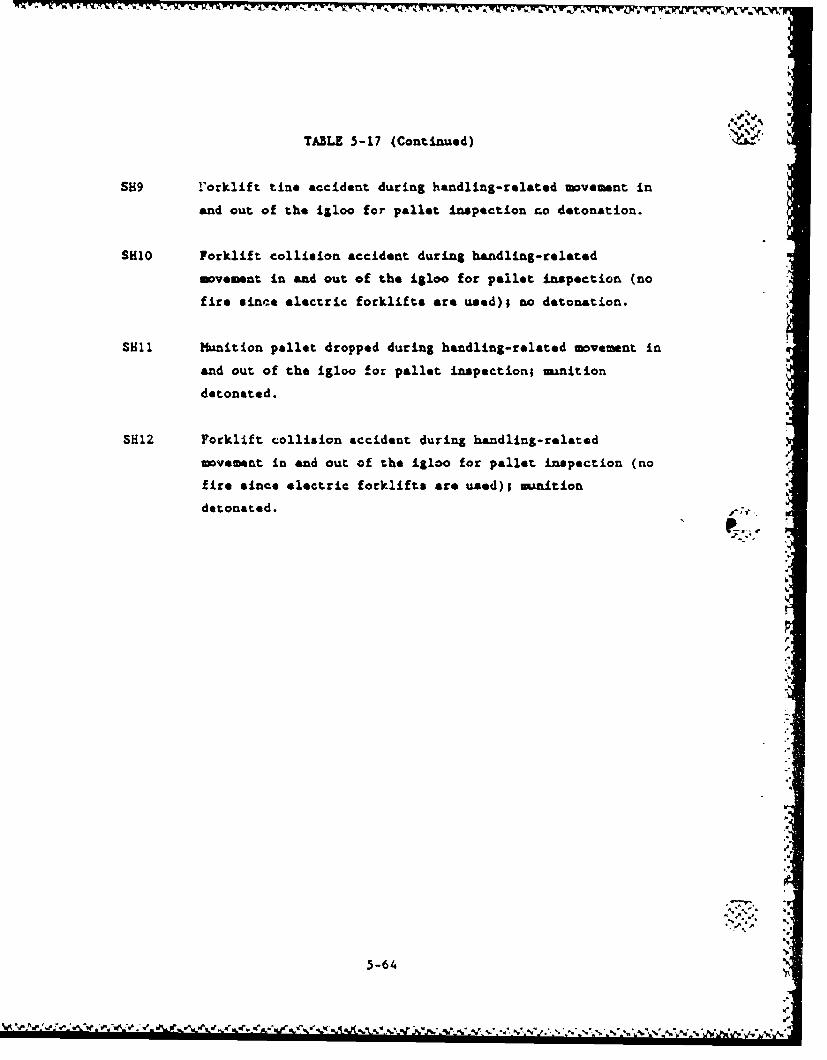
TABLE 5-17 (Continued)
SH9 Yorklift tine accident during handling-related movemnt in
and out of the igloo for pallet inspection rco detonation.
SH10 Forklift collision accident during handling-related
movemnt in and out of the igloo for pallet inspection (no
fire since electric forklifts are used); no detonation.
S1ill Munition pallet dropped during handling-related mvemnt in
and out of the igloo !or pallet inspection; munition
detonated.
31H12 Forklift collision accident during handling-related
movement in and out of the igloo for pallet inspection (no
fire since electric forklifts are used); umiition
detonated.
""1
'.j
5-64 "
•.'v,•''•'•',.eF• ,'%'•'€ •'.•r .. ••'•' ••'.•r, .r•,-,#-,•.,-•.• • , •, . • ,•,,,. .•,t.,r. ,,.•.,.... .,-
12W Jwwjr rh .. .r'ý-N-IK- "J -Kr -'b 'JW -,2%A -. a 11P V ' - . v-
transportation risk for movement of munitions even without overpacks
should not differ significantly for the following reasons:
1. The protection from impact provided by most manition casings
are at least &a strong as the currently designed onsite
package.
2. Moat munition casings provide a much protection from crush as
the package.
3. The possibility of a fire longer than 10 mn has been elimi-
nated by an administrativo requirement of limiting the amount
fuel carried by a truck to less than 65 gallons. Therefore,
even if the package provides a 15-mmn protection from an all
engulfing fire, there will be no difference in the risk
results for packaged or unpackaged munitions.
4. Thin-walled munitions such as the 4.Z-in mortar projectiles,
mines and rockets apparently will not be taken to a main-
tenanco facility for inspections since they are not listed in
Table 5-16. The package designed for onsite transportation of
munitions provides additional protection for these munitions.
For thick-walled munitions such as the projectiles, the dif-
ference in risk of whether they are in or out of a package is
negligible.
Table 5-18 presents the data used to evaluate the accident frequen-
cies for the scenarios addres&ed above. The frequency of scenario SLi 1was derived by determining the leakage rate for each munition type based
on the leaker data at each site and the total munition inventory at each
site. Since the two parameters are classified informttion, they will be
presented and discussed further in a classified appendix to this report(Appond~ia H ),."
F5- ."5
.. 5-65
4:- 'V
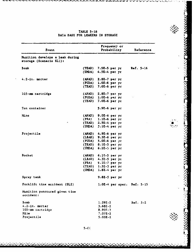
TABLE 5-18DATA BASE FOR LEAKERS IN STORAGE
Frmquencr orEvent Probability Reference
Mmition develops a leak duringstorage (Scenario SLI):
Bomb (TEAD) 7.5E-3 per yr Rif. 5-16(U1DA) 4.5E-4 per yr
4.2-in. mortar (ANAD) 2.8E-7 per yr(PUDA) 1.0E-6 per yr(TEAD) 7.OE-6 per yr
105-m cartridge (MNAD) 2.8E-7 per yr(PUDA) 1.0E-6 per yr(TEAD) 7.OE-6 per yr
Ton container 5.9E-6 per yr
Mine (ANAD) 9.0R-6 per yr(PBA) 1.1E-6 per yr(TMAD) 2.53E-4 per yr(UMDA) 3.1E-4 per yr
Projectile (ANAD) 4.9E-6 per yr(LBAD) 9.3E-6 per yr(PUDA) 5.0E-6 per yr(TEAD) 8.1E-5 per yr(UMDA) 6.2E-5 per yr
Rocket (ANAD) 6.1t-5 per yr(LBAD) 4.3E-5 per yr ,-(PEA) 5.1t-7 per yr(TEAD) 1.3E-3 per yr(U)IDA) 1.8E-4 pe" yr
Spray tank 9.89-5 per yr
Forklift tine accident (SL2) 1.0E-4 per oper. Ref. 5-15
Munition punctured given tine&ccident:
Bomb 1.29E-2 Ref. 5-24.2-in. mortar 3.68E-2105-n cartridge 8.90F-3Miae 7.07E-2 -Projectile 5.OOE-2 ,.. .
S) --- r
- ,I.
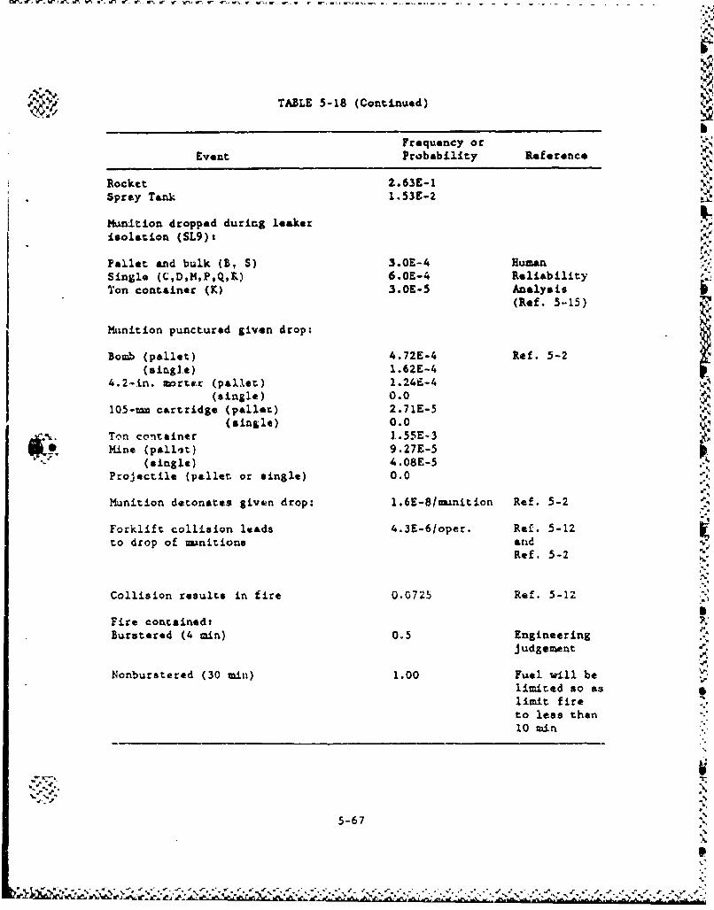
TABLE 5-18 (Continued)
Frequency orEvent Probability Reference
Rocket 2.63E-1Spray Tank 1.53E-2
Munition dropped during leakerisolation (SL9)t
Pallet and bulk (B, S) 3.OE-4 HumanSingle (C,D,M,P,Q,L) 6.OE-4 ReliabilityTon container (K) 3.OE-5 Analysis
(Ref. 5-15)
KMnition punctured given drop:
Bomb (pallet) 4.72E-4 Ref. 5-2(single.) 1.62E-4
4.2-In. morttr (pall.et) 1.24E-4
(single) 0.0105-n cartridge (pallet) 2.71E-5
(single) 0.0Ton container 1..55E-3Mine (pallat) 9.27E-5
(single) 4.08E-5Projectile (pallet or single) 0.0
Munition detonates given drop: 1.6E-8/Iunition Ref. 5-2
Forklift collision leads 4.3E-6/oper. Ref. 5-12to drop of minitions and
Ref. 5-2
Collision results in fire 0.0725 Ref. 5-12
Fire containedtBurstered (4 min) 0.5 Engineering
judgenent
Nonburstered (30 min) 1.00 Fuel will belimited so as
limit fireto less then10 min
5-67A
5-67 A
| %"•'•..'•.'• '.' .'' "J •'.. .. •%"'•".-'".'. -. ". ."."•" "." <-" "•" •.-.•'. '.-.-' -,-. •.-' -" ..- ' -" " .," •"-" - •" .'. -" ," 'e" .'"
5.4. SCENARIO qUANTIFICATIONI
Tables 5-19 and 5-20 present the results of the accident sequence
frequency analysis for all the storage scenarios discussed previously
except those which were initially screened (i.e., SLIO, SL11, SL12,
SL13, and SL14). From the results it is evident that the following
sequences could be screened out (from all eight sites) further based on
the 1.0 x 10o1 0 /yr criterion:
SL17 - Large aircraft direct crash; fire contained in
30 min.
SL21 - Large aircraft indirect crash; fire contained in
30 &in.
SL23 - Tornado-generated missiles cause munition detona- %',
tion upon imact. "* ISince handling-related accidents are given in terms of events per
munition operation, no screening can be performed witho,,kt divulging
classified information.
Table 5-21 presents the results of the accident scene.rios related
to the planned surveillance and maintenance of nanitions over the 25-yr
continued storage period.
1
P",.
5-68
- ", , , _ ". .' .. "." .. . .- -.- , -.
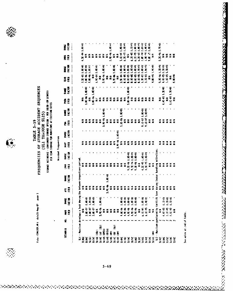
I-
I-
te: m iinuisma
S. . . w
la v . . . ..t. . .
-i• a • ... ... a... aa .... .. ..
1* T• • * . . . . a . . . . . . . .
"r - ..------- -- ---------- -- . . ,
i - I"
t C - - -=a c iCi i C - aa
22
5-69
0' ~ Z~
"-• • • • "' W 3•" ' •"" •• •T '"* •• - .
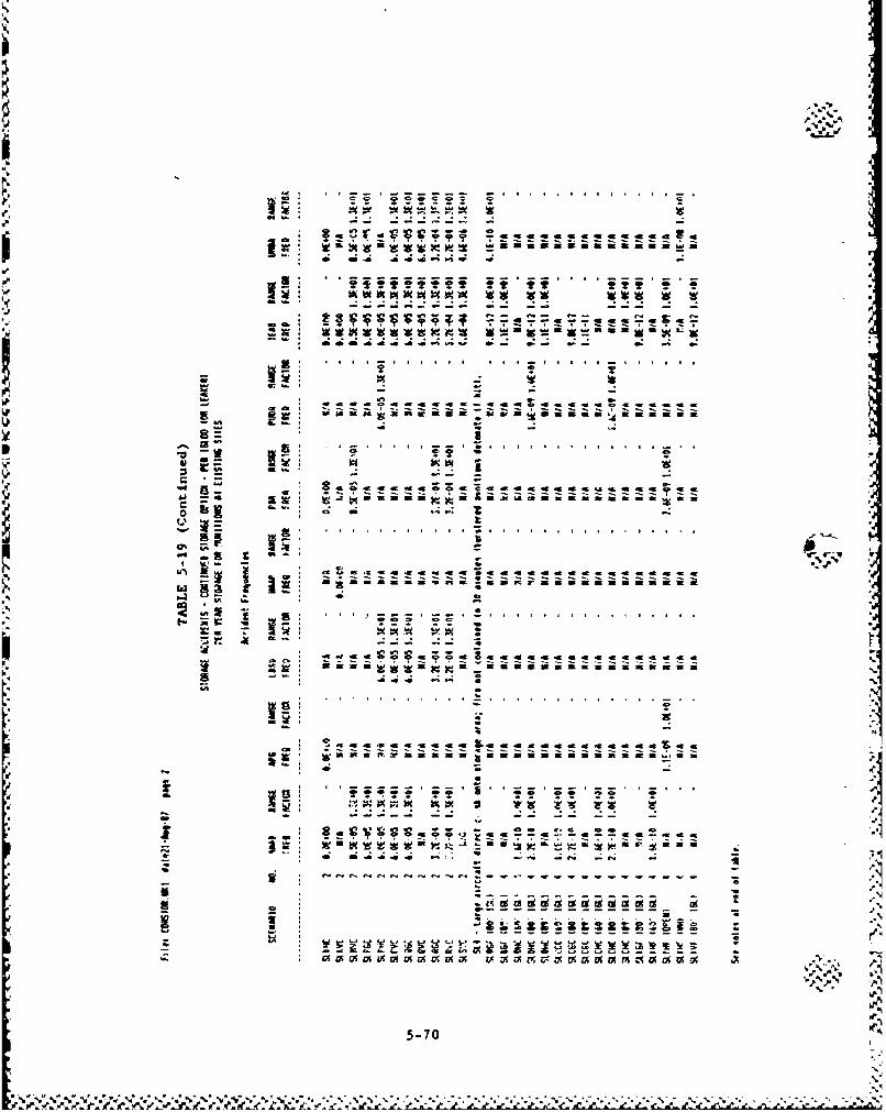
.- . . .. .c .0 .= . .
pW W
*,1 m ft m 41Cm
cv - - -- - --
& - w w*
.4 4
-rc-
.0 A? 5'-A.e - r
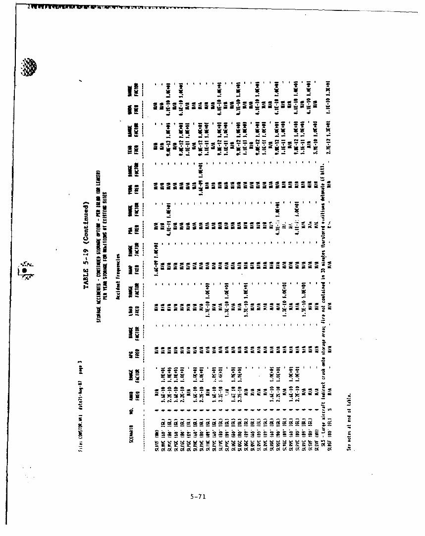
J~~~~~~~1 on3 mI'rUU w~ W!IU OnP1]7 J ~UI
a - a a a a a - a a- S- I S S a - - S -
2?~~~ 2 2 2-~ ~ - - -
49 al
su~ea. ~e~..!~~~
t oo . * I *cwLoo m4 -ai w 4L 44F~ * ~ *
-m
C -9
ot o ,
-- - ' o
5-71
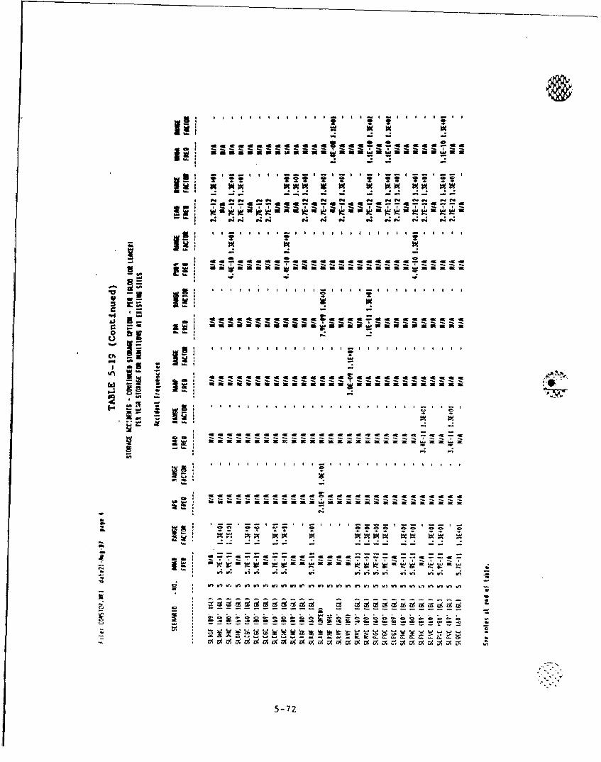
-6at a e -at e a a m eI K I ft 2 a 4I me a I6 2m 4
m a =% %L
tu- e 42 e. e e- w4I M
a ai-Aiiii - Ii i i iiaii
29 a m
.- ...... . . . . . . . . . . . . . . . . . .I a w w c-i -a. -a w w -. x w
CA I I a a ; aK I a I I M I I
-a 2a a 2
I a
r a - a- - 77 - - 77 7 7 ---.--
- - -
C o
=i a O a a a a m m a Ix al I ix X ý a 9 a a x ix
5-72
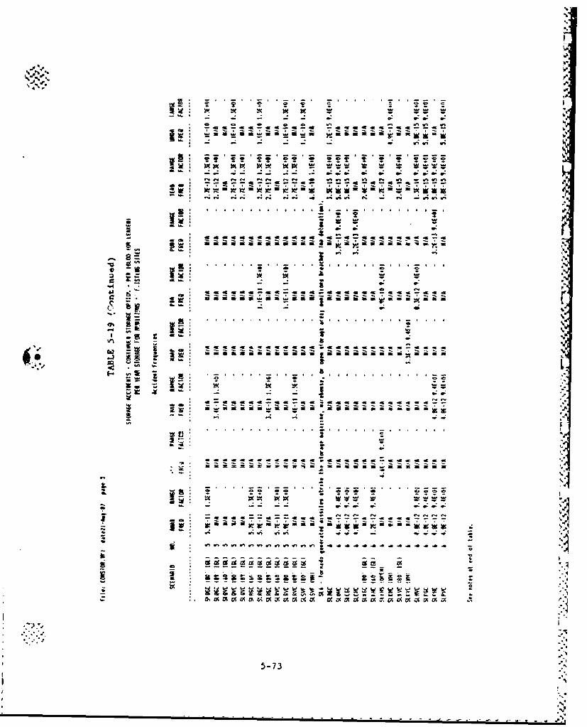
a-
41..
4-•
.. . . .. . . .., . . . . .
;00i a, w w-j * -- - - - - --n
* •• --- --... .. .. . .. .. . . .
: : 5
! • •* - - •: .
T..-Z
--------- - - --'
42 - a -- -~
*...a aa.-- - u . a .-
.ce
"v •i ac .*4naa&wa
5'-
-' g ~~ a. .:~r au.o
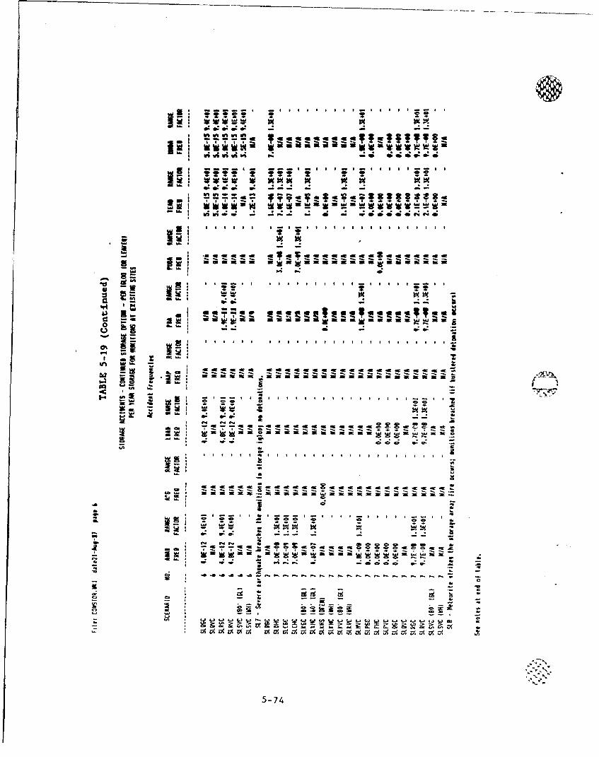
lij g0: moo 0: 0: 0
.m... . . . . . . . . . . . . .
~Z
a w ww w ma
inu.
.~~~~ .- . . .. . .. .-
~~c * n m a
-- -- - - - - - - - - - - - -
5-74
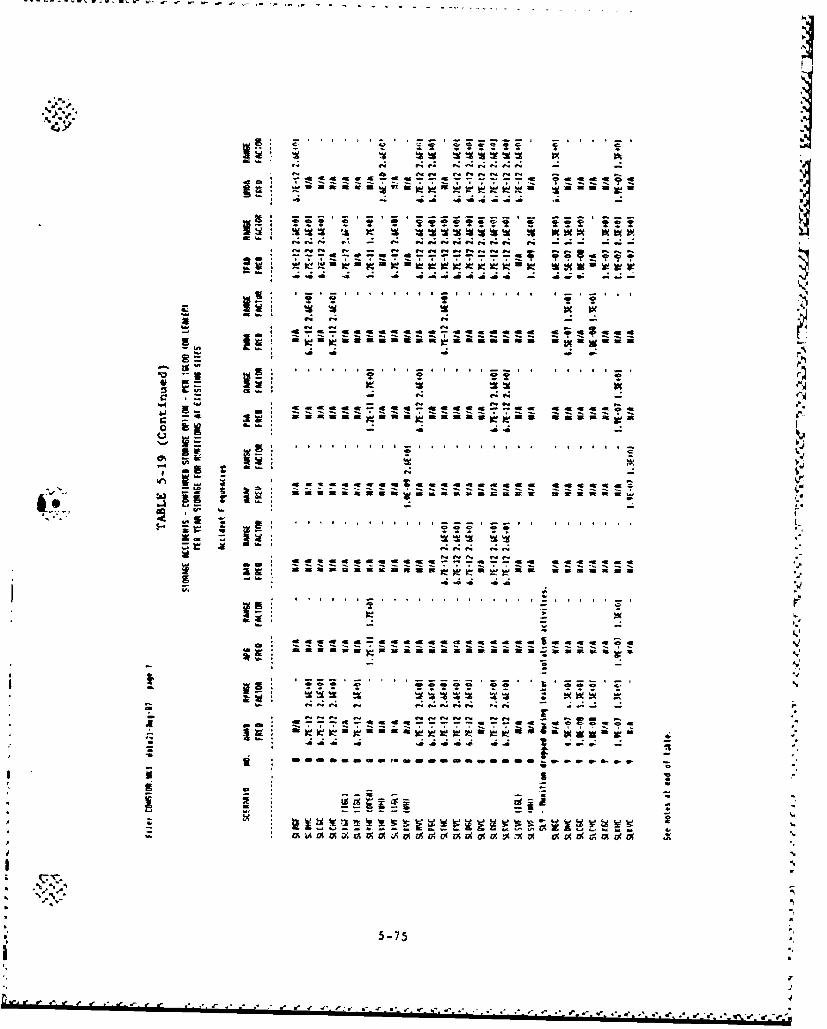
S. . . . . . . .v
nrwr.~~~~~~ ~~ r.-.~ .' . . . . .r .~a, . . . . .- . .- . . .
a 19
: 4
*• -.. c... .. a 75 • : ..'-
L s -h
* a- 4a mC a .e ft
5-75 "
a: z;i'ii't ~WOCCt . 0
Ck
I: I
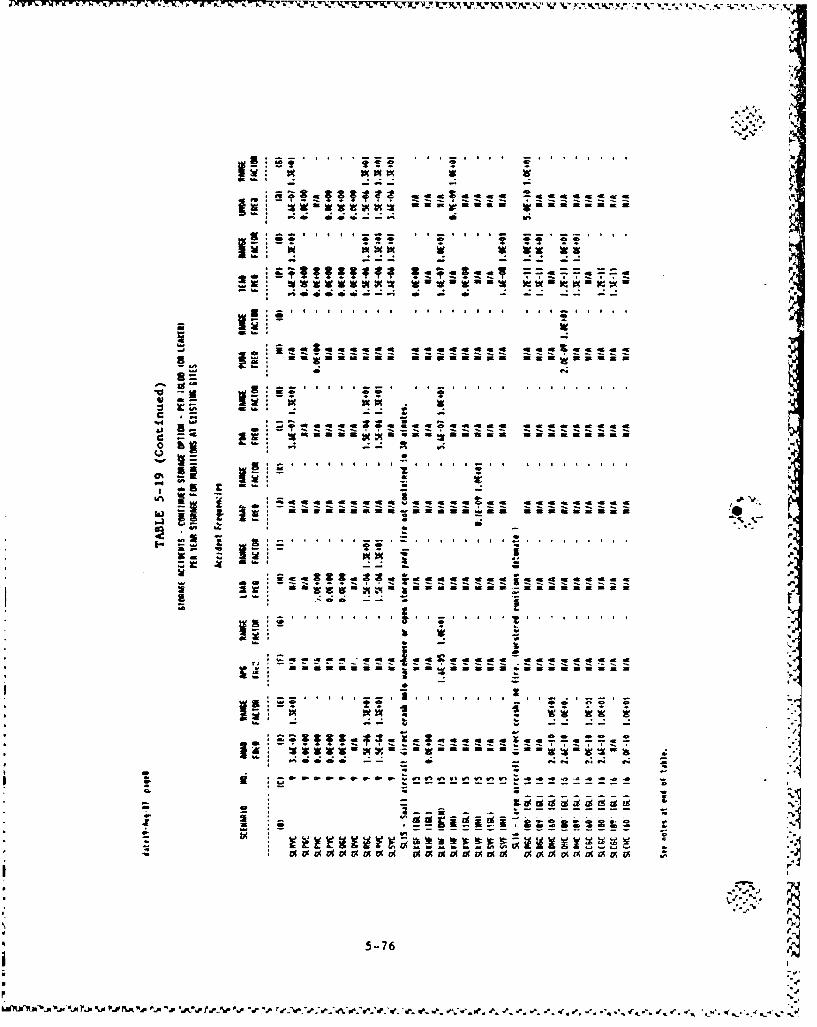
-- -- - - - - -* ,, i
.". . ...
.. . ......
. = .W.2
w
a ' .* .. . . . .. .= . i . . . . . . . . . . • ,mm m.ma w~ e a
•~~~~~ W• I• X I•• • ° ••_
.
a 0 9a9C 9 V(V 9aaV a ocaam a a m
• 5 - 7 6
I w
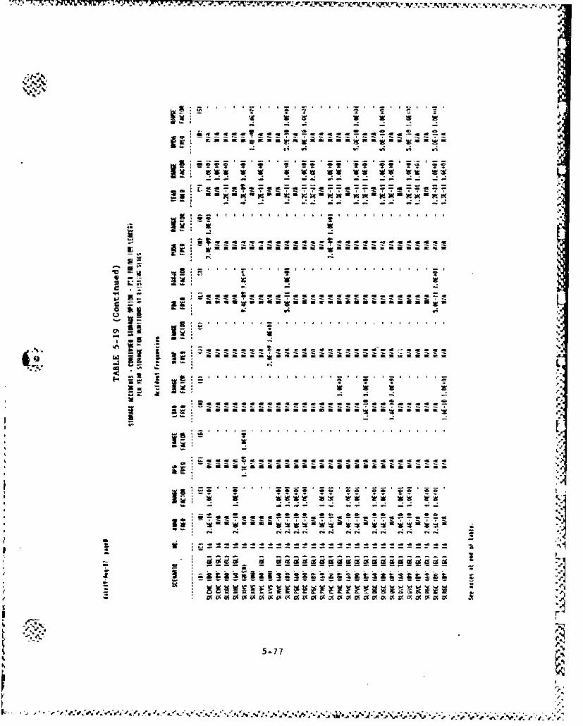
"S .~-* S . . . .
- - - - -- - - - - - - - - - - - - - -4
- - -. - - -
-5-7
-~ acC.,ccca a a %
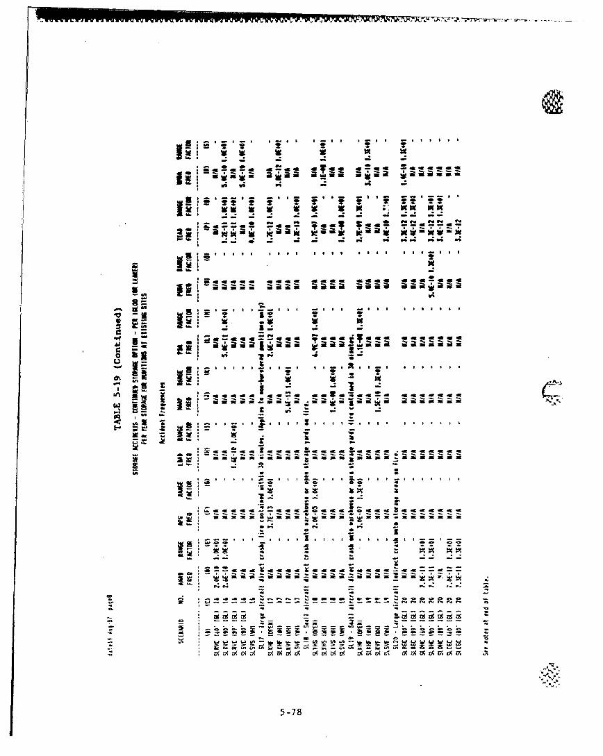
W6 's
~V; W; P; - 4
ift 2
I~V~ i WIWI W man-- - - - - - f
-- * PS P .. i *. ~ PS P
a.1
da cm e ~e~
*t T
~~4 -m -K c 49 * e a a x w 4 a a ma a s a
- - - - - -- - - - -
Eg PS r. .g vi- Z x& g;g ;I
q.4 ~ - -PS e e. 5ain5-78a
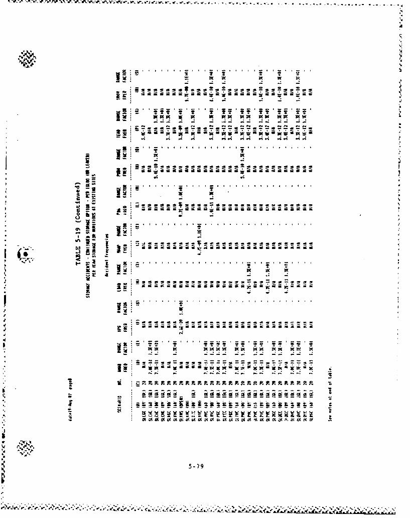
.'•" ... .. . . . . . -. . . . . . . . . .-
5-79
rX2 V w 0 a ~a m
gi !i*!i - - - - -
*aaaa ma a ag d it d w d d aa a a d a ag a a a ag &9 a
-. o . o .o - . . . ... . _ . . .. .
5-7
•.•'-'•'•' • '• '• ,-.'• ',.' -• in'.c.,'-"aa ". a "•.-"'-,"'.a -ea -e-c'a-ae''eae-.a..' . -- •-•S...* -a. .. • .. .• • •,l• . . '• • • t• l
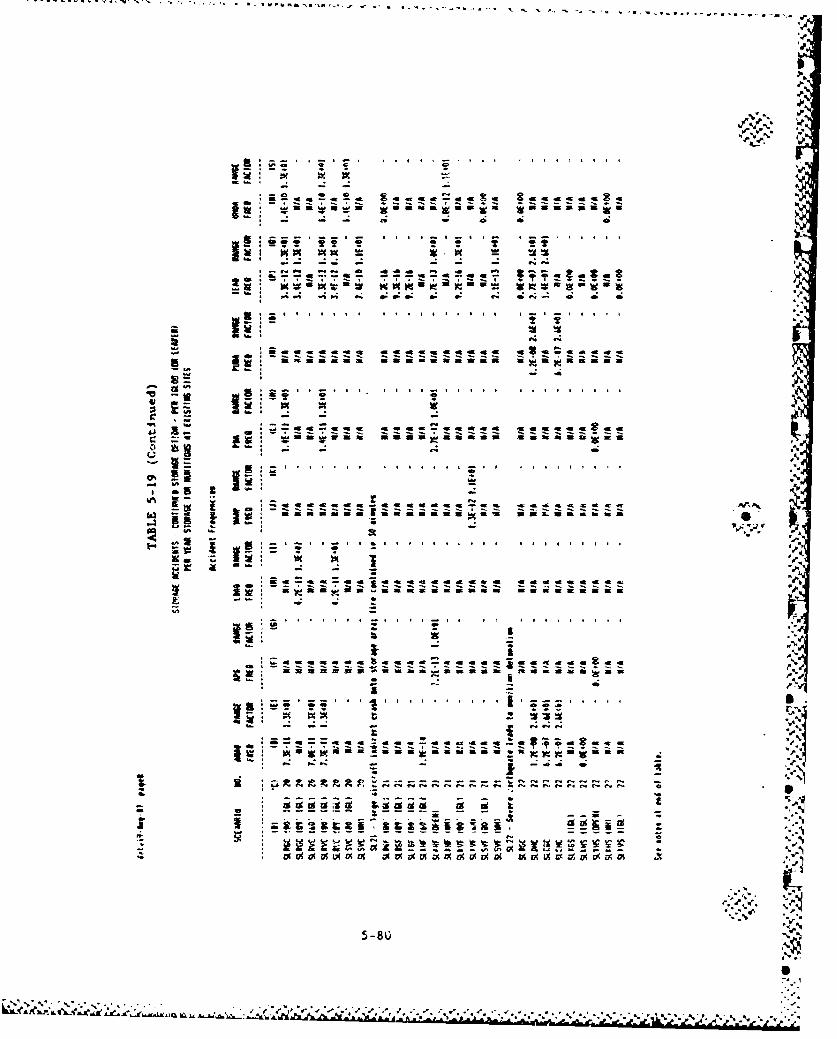
"-rLC Wb -- - - - -- "-. " -,.., . --x.. .. . .... -
C) '4
ILI.
!E "z l Ar, N*! I- .. . - ... .. .4I I .. I . I
"a. W)=
* ~ ~ ~ ~ ~ ~ ~ - :z tzr . S . - 4 . - ~ *
isl
of . m m I I a " a I Z C M I
"" . . . . . . .. ..
*. -_-. *, . ,..._ ,.. . . .. .. . .. .. .. . .. ..
I- " f 'i
I - .4
.*.. . . . . . . . C S . . . .. . . I . . . . . .
o --- '., .",,
* ~-I
2 ~.•
'1%
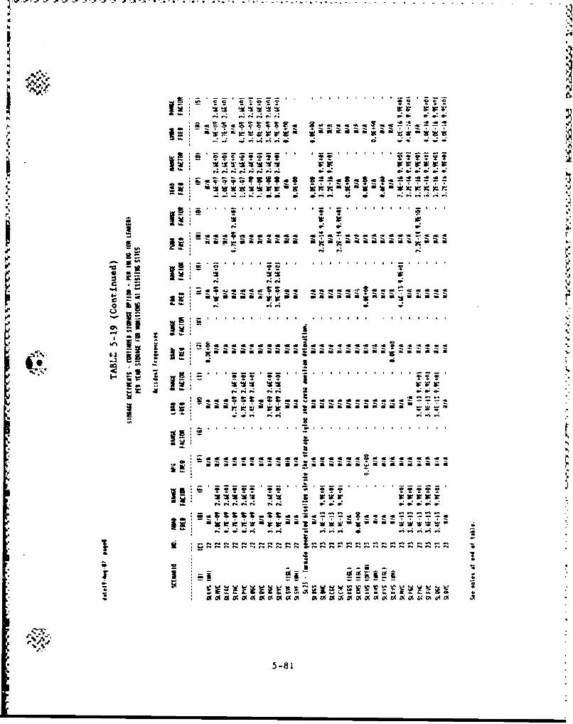
.• ... . . . .. . . . . . . .....
4p: e:~
so cc
S.• S. . .. . . ,
,,� ,. . .. . . . . . .
IV- ii ii- - - - - - - - - -
- -.- -.. . . . . . . ... .
at. :": 0 .,.. 1 5,
*, -.-- , es , , , ,- . . ..-.
59* _Ui 7TO s 55i_5 i
5-81
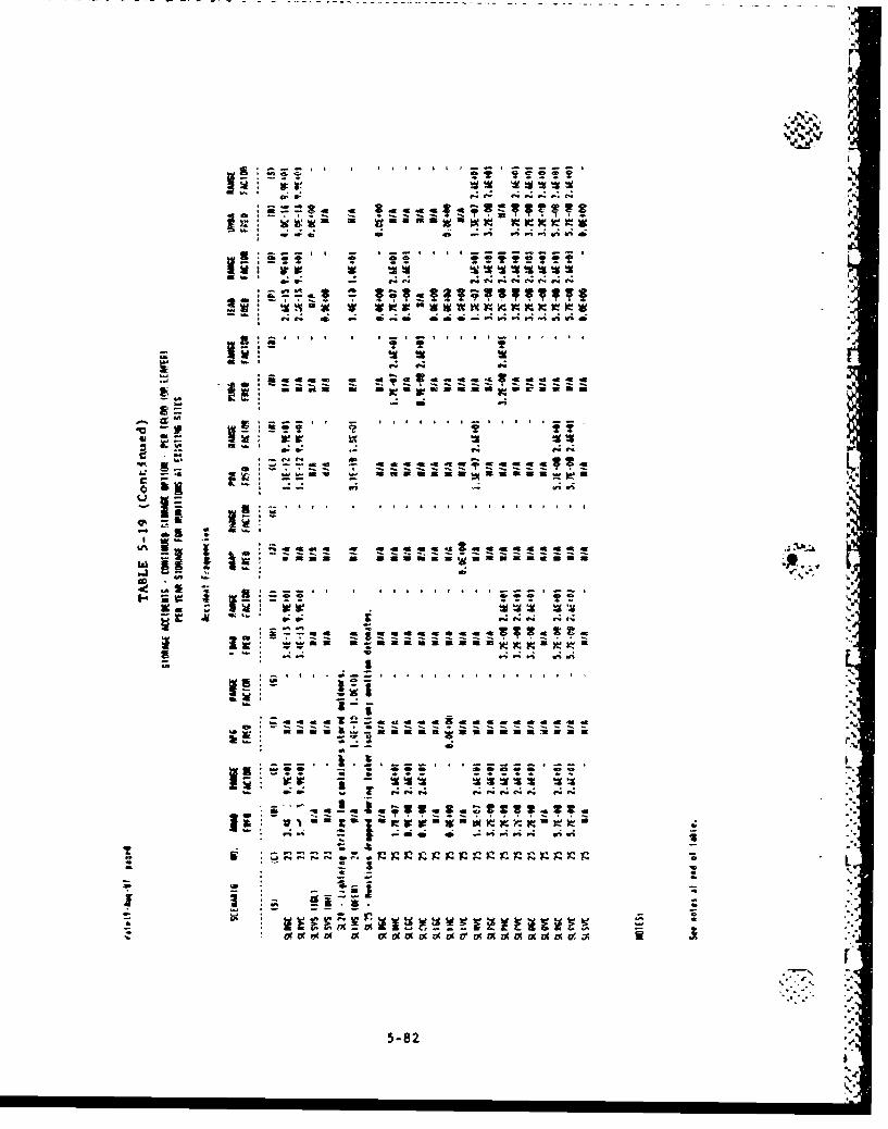
41?
I- -- -. , 1
a a n. 44.,i~
.- 0- .4~ "44 .4f.; . C4 P4 4
di 0;4 P4P.4 4W
-p8
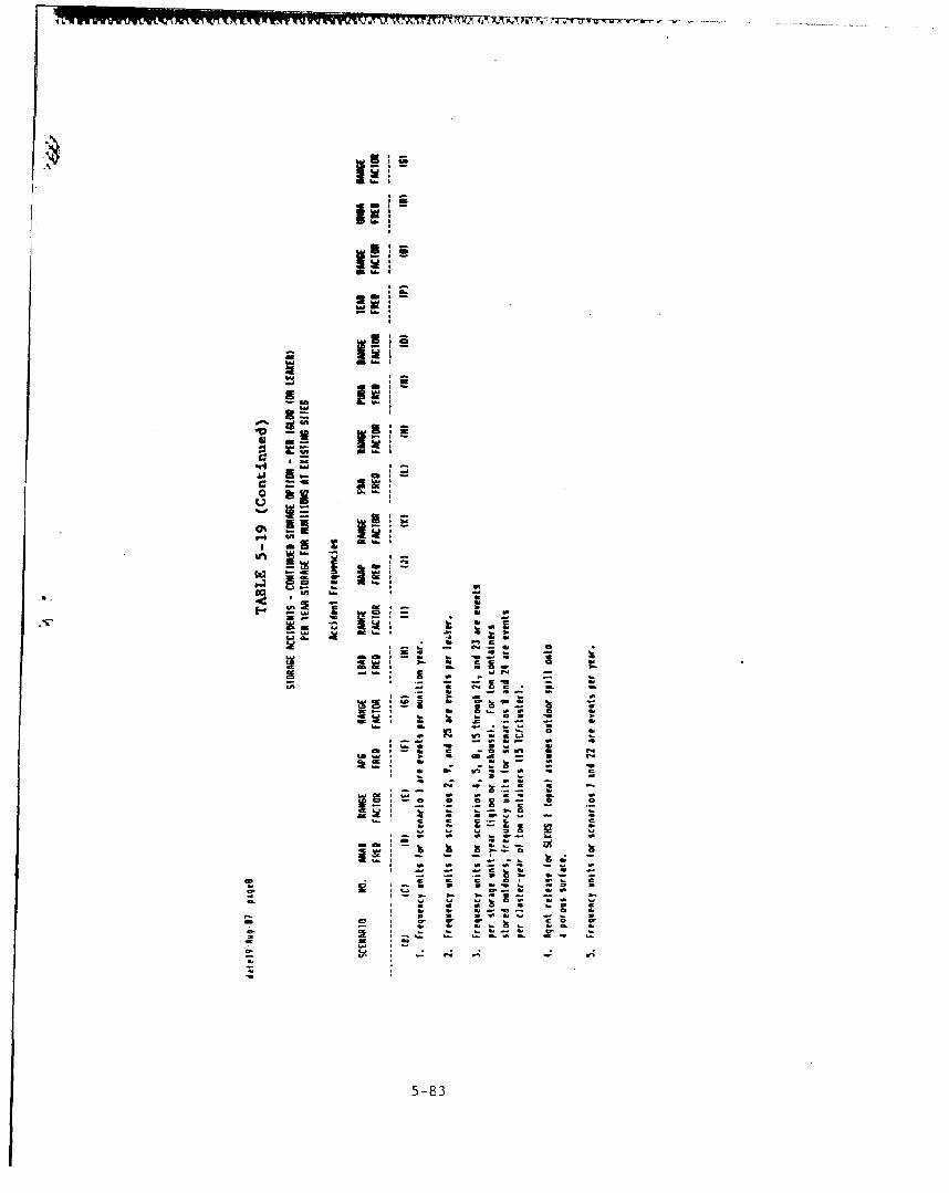
m~.InkiI
4J Eb
-l a ~ -Ib
U, -Icz Z la
-- ft
UI~d C-~ a MC~t
a~ U c-iis
~ : 1~ ~CD
~ - 5-83
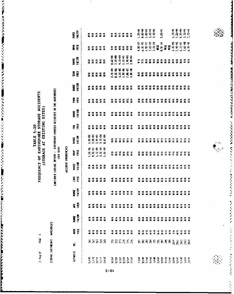
c~~~~ -W -a -9t cc
- ~ ~ ~ ~ a. - -- ------ - - .- - -c
af w- - -it a) ~ m = 3 ma m m
C- I- Z a I . I eI cma .3
a M 319it w 3z it m w ft w wn
Ia eC C CC C C C4
CC CCC 49CC -9 -W -6 .9 C
- - - -- -
U4 tj Z; 4 r 4i47 r. V 9 U 9zU
p CCC CCCC C CC CCCC5-844
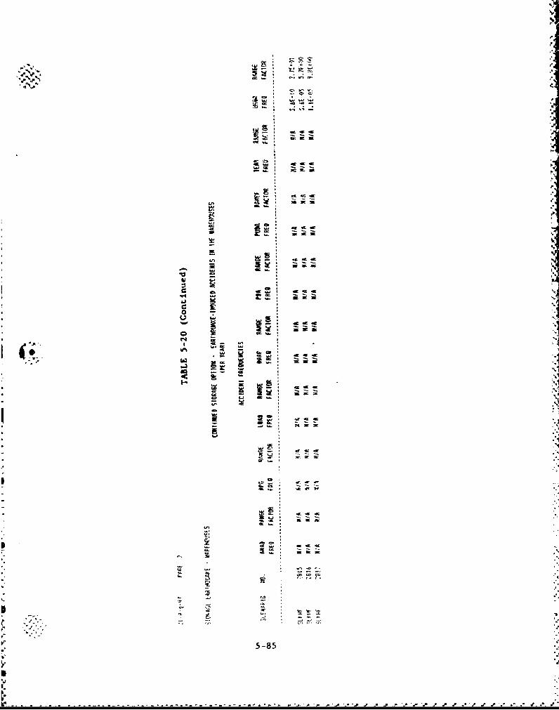
W. mc sit
ot
m me
re -
0 U--S U *
g*~ - -
Li
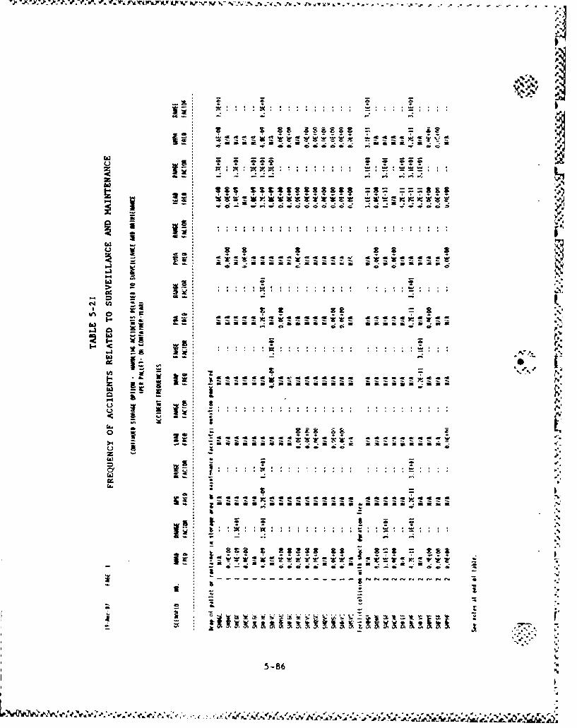
-- - - --
fl. -.I.
Esm :,.-, m a w44 D *, , , .,, .._ .-. ": : : ..
C- W z z :
" • .•. -, .. . .•a: ,
¢X• .. . , ,: ', ', : : :;::, I ,,,....
is
Ua agom ma n a n w a gs a amma
-- -- .
* :
,g .. 1,
4%
5-86 •
1-' a:
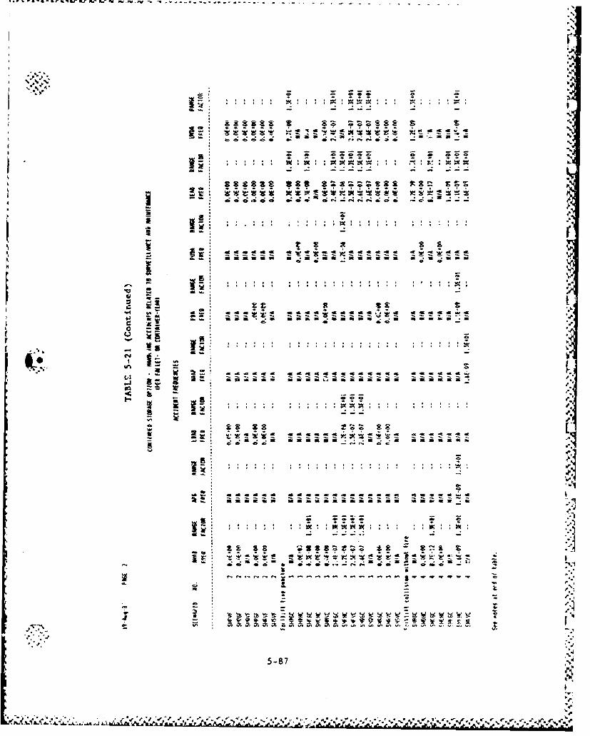
- - .. - - .
16r
, - ;" "lev. A w~v *.. w*=
de i 49 ar ?In 1So -
Saof "° a
- -
Is2 22R a~~~Z ftr m
- - --. -- ---
5-87
S.. . . - t % I : :2p
A *;i YK
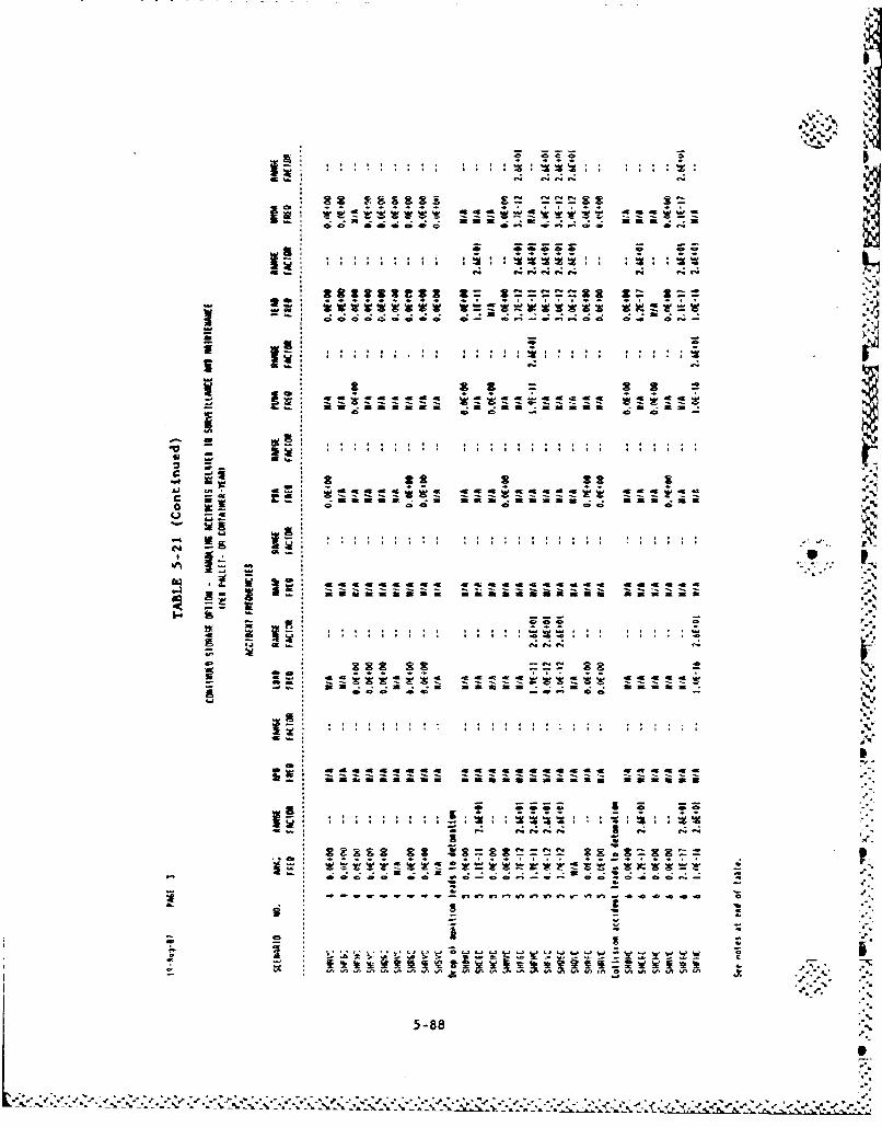
20~~~ lo w . 044ý
4s C; 4iE C; z 44 4 t*
*s a
ad
Umifififa a Ia aiam a
-8 04 dg -6 -6 m -c- K 4
- if-
-5-8
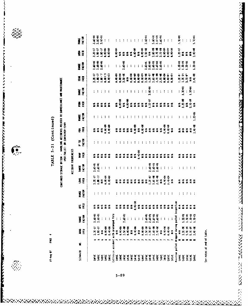
0 .. 4. e4 A-
. . . . . . . . .. .t .t ... . .
• . . . . . . . . . . -a.. . . . . .a•.
SWW W = ....... ~ -j
de ds c. ede.~rr -- - --
- m . C a e.. . .a _-C e
m m at
-- - - - - --
" 5-89
S-89
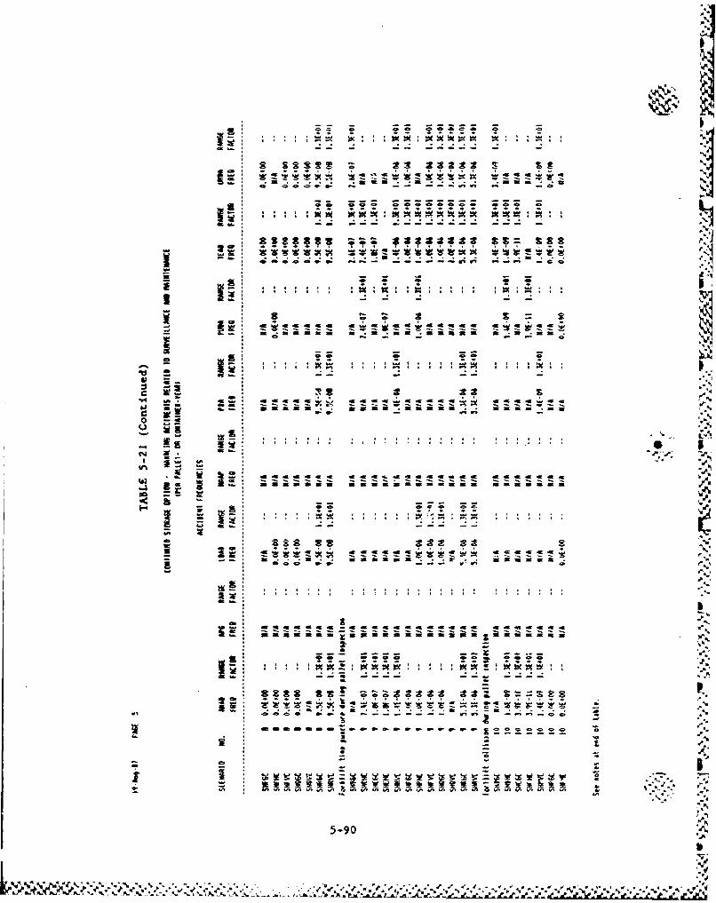
W, 4
aaaaa ;-ff a~zlmimm mmm w aw Q
ass as 22 as
!5 :g ýx
-W -f d6
ZVI
-5 9
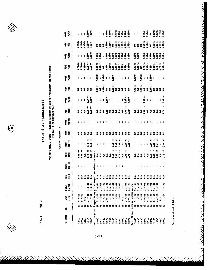
14 .. '. f4F c 4 11 4
.0. W:.; 21 000 0 c
mm m amMI m 3
ag
4r 00 9 -a vý4 cemwuea
3 ~ ~~~ ZZ z. z4@ 4@ 4
-.. Z
m f-- V4f 4 4 4 4 4 4 C44 44.
it!!v- .. ,
i y~ w E-It 0
- - a , - .1
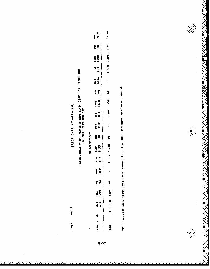
!•- ! " - •._
-- I
-- -_ I'
,,-,
- r- , *Z-.
m..',,-
- a -
r
" T h e t r e n d s i n d i c a t e d b y t h e f r e q u e n c y r e s u l t s a r e a s f c l l o w s :
Externally-Induced Events
1. Tornado and high wind
a. Munitions stored outdoors or in warehouses are generally
"more susceptible to tornado strikes. APG, PBA, NAAP,
TEAD and UMDA have warehouses. PBA and NAAP are in
Tornado Zone I while APG is in Tornado Zone II (Zone I
has the highest tornado frequency). TEAD and UHDA are in
Tornado Zone III.Jw
2. Meteorite strike
a. Munitions stored in warehouses are more susceptible to
meteorite strikes. Since fire is generally present, a
i I:~meteorite strike may involve the entire warehouseinventory.
S3. Aircraft crashes
a. Munitions stored outdoors are generally more susceptible
to these events. APG, TEAD and PBA have ton containers
stored outdoors. However, the aircraft crash probabili-
ties at APG and PBA are relatively higher than the other
sites.
b. Igloos provide minimal protection from direct crashes of0.I
large aircraft. The accident becomes more serious whenSburstered munitions are involved.
5-93• .. .. • •' • • " • • • • • • • • • •'• • " •'• • " ,'. •'' ,'.' '. ... . .., ,. . . .'. ,-.'.,' -.• .• • € • •. .¢ p-. 4
c. Large aircraft crash frequencies at APG, LBAD, and TEAD •
greatly increase for the air option because of the oddi-
tional landings and takeoffs at these sites.
4. Earthquakes
a. Earthquakes, particularly in high seismic locations such
as TEAD, could cause stacked munitions to be punctured.
However, the probability of having a probe present inside
an igloo is quite low.
b. Detonations due to earthquake-induced drops are at least
two orders of magnitude less likely than punctures.
c. There is a significantly high frequency earthquake-
induced agent releases to munitions stored in warehouses
at NAAP, TEAD, and iYMDA.
Leaker-Related Events
I. Forklift drop accidents can occur more frequently than fork-
lift tine punctures.
2. Use of a lifting beam instead of a tine leads to an order of
magnitude decrease in drop frequency.
5
.-t
5-94
*p6. =
St.
- '%'4.....................................................
p
5.5. UNCERTAINTY ANALYSIS
5.5. 1. Overview
The frequency results presented in Tables 5-16, 5-17, and 5-18 are
median values. The values shown in the range factor colum represent
the ratios of the 9 5 th percentile values to the median values. The range
factors vary from 10 to almst 100. The tornado frequency results have
the highest uncertainties largely because of the difficulty to accu-
rately model the probability that the missile will be in the proper ori-
entation to penetrate the munition and actually how many missiles per
square foot of wind will be present. The ability to model low-impact
detonations also lead to large uncertainties in the final results. The
data available are scarce and sometimes not directly applicable to the
scenario being analyzed. =
5.5.2. Error Factors
In those cases ihere sufficient information exists to determine the ,
upper- and lower-bound values, the error factor was derived by assuming
that the upper-bound value is equivalent to the 9 5 th percentile. The
engineer's best estimate is taken as the median value based on the prop-
erties of the lognormal distribution. This choice is rather cnnserva-
tive since the mean value of the resulting distribution becomes larger
than the best estimate or recommended value..4
In many cases, however, the data sources were limited. Therefore,
the assignment of error factors was entirely based on engineering judg-
ment, taking into consideration the important parameters which may
influence a particular variable. The generic guidelines for the uncer-
tainty assessment is shown in Table 5-19.
5.5.2.1. Tornado Sequence Uncertainties. The frequency of the init.ýat-
ing event itself (i.e., tornado wind of sufficient intensity to generate
5-95
,; ..- . %a..%..%... .. . . . . . . .. %..... . . -. ,-
missiles occurs) is assigned an error factor of 10 per Table 5-19. The
conditional probability of a missile hitting the structure and penetrat-
ing the muinition is assigned an error factor of 50. As explained In
Section 5.2.1.1 (Eq. 5-2), this event is the prouuct of four variables.
The uncertainty is largely due to the variable D. which is the number of N
missiles per square foot of wind. The conditional probability of a
burstered munition detonating when hit by a missile is assigned an error
factor of 2.
5.5.2.2. Meteorite Strike Sequence Uncertainties. The frequency of a
meteorite strike is assigned an error factor of 10. The conditional
probability of a meteorite penetrating and rupturing the munition is the
product of (1) fraction of stone and iron meteorites capable of pene-
trating the target; (2) target area; and (3) spacing factor. This event F,
is assigned an error factor of 10. The uncertainty is largely due to
the fraction of stone and iron meteorites capable of penetrating the
structure. lip.
5.5.2.3. Aircraft Crash Sequence Uncertainties. The aircraft crash
frequency is assigned an error factor of 10. Aircraft crash accident
sequences with or without fires (from impact) have been considered. For
this reason no uncertainties were assigned to either the probability of
having a fire (0.45) or no fire (0.55). The uncertainties associated
with the structural damage (i.e., igloo or warehouse) given an aircraft
crash are given in Table 5-8. For events with probabilities greater
than 0.1 the uncertainties assigned followed the guidelines given in
Table 5-19.
5.5.2.4. Earthquake Sequence Uncertainties.
Storage Igloos
The initiating event, earthquake occurs, is assigned an error fac-
tor of 10. The conditional event, munition punctured given drop, is
5-96 P.'
1 .° *
assigned an error factor of 5. The puncture probability is a function"of drop height, weight and presence of a probe of sufficient length and
density. The uncertainty is largely due to the last variable. Note
also that no uncertainty from errors with the models has been considered
since this is beyond the state-of-the art of present day uncertainty
analysis.
5.5.2.4. Earthquake Sequence Uncertainties.
Warehouse Storage
Event 1: Earthquake Occurs
The initiating event frequency is assigned An error factor of 10.
Event 2: "K" Warehouses Damaged by Earthquake
ý4 Uncertainty factors for values above 0.1 are taken from Table 5-22.
* ... For probabilities between 0.01 and 0.1 an uncertainty factor of 3 is
recom•mended. Probabilities below 10-2 is assigned an uncertainty factor
of 3. The uncertainty distribution in each case is lognormal.
5.5.2.5. Handling Accident Sequence Uncertainties. All initiating
events associated with mumnitions handling (i.e., drops, collisions,
forklift tine punctures) were assigned an error factor of 10. The con-
ditional probability of puncturing the munitions given any one of the
initiating events is assigned an error factor of 3. The probability of
causing a low-impact detonation (i.e., drop from 6 ft or lower) is (-assigned an error factor of 10.
.5
5-97 "
~ ~ - J~.* -~ . t ~ ~ - .d~S%
5.6. REFERENCES
5-1. Science Applications International Corporation, "Probabilities of
Selected Hazards in Disposition of M55 Rockets," U.S. Army Toxic
and Hazardous Materials Agency, M55-CS-2, November 1985.
5-2. "Supporting Calculations for the Risk Analysis of the Continued
Storage of Chemical Munitions," GA Technologies Inc., (Issue 2),
Volumes 1, 2, and 3, August 1987.
5-3. Department of the Army, U.S. Army Materiel Development and Readi-
ness Command, "Safety Manual," DARCOM-R-385-100, August 1981.
5-4. Coats, D. W., "Natural Phenomena Hazards Modeling Project:
Extreme Wind/Torrado Hazards Models for Department of Energy
Sites," UCRL-53526, Lawrence Livermore National Laboratory,
February 1984.
5-5. Lawrence Livermore National Laboratory, "Explosives Handbook,
Properties of Chemical Explo3ives and Explosive Simulants,"
March 16, 1981.5-6. Zelephone conversation: R. Perry (OPMCM) and C. Everline (GA),
June 15, 1987.
5-7. "Status Report on Packaging Concepts for the Transportation of
Chemical Munitions," presented by MITRE Corporation to OPMCM,
June 17, 1987 (modified on June 26, 1987).
5-8. Blake, V. E., 'A Prediction of the Hazards From Random Impact
of Meteorites on the Earth's Surface," Sandia Laboratories
SC-RR-68-838, December 1968.
5-9. Solomon, r. A., K. C. Erdmann, and D. Okrent, "Estimate of the
Hazards to a Nuclear Reactor From the Random Impact of Meteor-
ites," Nucles- Technology. Vol. 25, January 1975.
5-10. Clarke, R. K., et al., 'Severities of Transportation Accidents,"
SCA-74-0001, Sandia National Laboratories, July 1976.
5-11. Weals, F. H., and B. Finder, "ESKIMO V Magazine Separation Test," N
NUC-TP-6076, Naval Weapons Center, China Lake, February 1979.
5-98
,I. ,' . ., • % . . % .- . . . - , - , . . - . , . - . - . . . . . . - . . . . . .p.,•'e.••:.•.-•..÷e,.e,,....' .• ,,:.• ,.,.,,•' ;,• ,•.;.• . .. L'---- ''"'..- .
5-12. tacGorman, D. R., t al., *Lightning Strike Density for the Con-tiguous United States From Thunderstorm Duration Records," U.S.
NRC Report NUREG/CR-3759, April 1984.
5-13. Flood Plain Information Part 11 Arkansas River, Caney Bayou,
and Tributaries; Department of the Army, Corps of Engineers,
Vicksburg, Miss., November 1973.
5-14. Bell, B. J., et al., "Human Reliability and Sensitivity Analyses
Supporting the Chemical Munitions Demilitarization Risk Assess-
ment," Battelle Columbus Division, July 10,1987.
5-15. GA Technologies Inc., "Risk Analysis of the Continued Storage
Option," GA Draft Report GA-C18564, Rev. 1, November 1986.
5-16. U.S. Army Armament, Munition, and Chemical Coaiand, "Quarterly
Chemical Munitions Leaker Report (RCS-RCQA- 123, CIQesified),"
October 15, 1985; January 1986.
5-17. "Cost Estimates Prepared in Support of the Transportation Concept
Plan," Draft Report Prepared by MITRE Corporation, June 1987.
5-18. "Independent EvaluationlAssessment of Rocket, 115-•n• Chemical
.1' Agent (GB or VX), M55,n U.S. krxmy Mtgterietl Systermn Analysis
Activity (AMSAA), October 1985.
5-19. Meeting at OPMCM, Aberdeen, Maryland on August 13-14, 1987
(Attendees: OPMCM, ORNL, JBF Associates, H&R Technical
Associates, Battelle and CA staff).
59
I.
5-99
6. QUANTIFICATION BASES
6.1. HANDLING ACCIDENT DATA
All initiating event frequency accidents, except for forklift
collisions, were derived from the human reliability analysis and are
discussed in Section 6.2.
The forklift collision accident frequency wss derived from
Ref. 6-1. In Ref. 6-1, accidents were defined to include incidents
that result in fatalities, injuries, or property damage. The basic
truck accident rate is 2.5 x 10⁻⁶ accidents/lmil. From Table II of
Ref. 6-1, the percent of accidents leading to collisions with trucks,
autos, and stationary objects and overturns is 89.35%. Table III of
Ref. 6-1 also &how that 502 of all Accidents oicur at speeds of 30 to
40 uph. ,
To convert the basic rate to accidents per operation, the opera-
tor's exposure time in the highway is determined. If the operator was
traveling at 35 mph, the exposure time is 1.7 min.
In order to apply this information to forklift collision eccidents,
the following were assumed:
1. The total operator exposure time during the forklift operation
is 10 min. This includes the lifting of munitions from the
stack, moving them to another ares, and unloading them.
2. The time to travel from one point to another is assumed to be
one-thlrd of the total time, or 3.3 min.
6-1
.,Mgt If
3. Forklift collisions will occur at speeds no greater than
40 mph (i.e., tw forklifts traveling at 20 mph).
Therefore, forklift collision accident rate ist
3.32.5 x 10.6 x 0.893 x m1 - 4..3 z 1O-61operation
This median value in assiSned an error factor of 10 on the basis that
the data is only for 6 yr and ther4 may be other unreported incidents
mre directly related to forklift operations.V7M
Reference 6-1 also indicates that 25% of fires result from
collision-type accidents. It is not evident from the data if fire
from collision is directly proportional to truck speed. Our analysis
assumes that it is. Therefore, the data was modified as follows:
Probability of fire - 0.25 x ' 7.9 - 0.0725 , .
where the factor 0.29 represents the percent of collisions occurring at
less then 20 mph.
4.
r.i
,P,,
12
6-2"Žo,_
? 2 - • ;-= ... . S
Human-error probabilities were quantified for use in the handling
scenarios uaing the approach to human-error estimation described in
NUREG/CR-1278 (Ref. 6-2), probabilities of human errors wre estimated
based on several performance-shaping factors such as iunition config-
uration, handling operation, clothing level, and crew size. These fec-
tors are identified in the discussions that follow on the derivations of
each estimate. Table 6-1 lists the error probabilities estimated for
puncturing or dropping a munition basd on each of these factors. These
error probabilities will be incorporated into the handling scenarios as
shown in the data tables in Table 6-2.
1. Puncturing a munition. The basis for the error estimates
is taken from Section 4.4.2 of Ref. 6-3 (pages 4.4 through
4.26). This reference gives 4 a 10-5 as a data-based estimate
of the probability of handling errors using forklifts for the1''.0 rocket stockpilea. This is an estimate of the likelihood of an
"error in forklift operation that potentially could lead to a
warhead rupture while attempting to isolate a leaking rocket
inside the storage igloo.
That estimate is based on conditions that do not entirely rep-
resent those assumed by this study; namely, that a three-man
crew will perform all forklift operations. In this study, it
is assumed that a two-man crew will perform all forklift
operations--one driving the forklift and one guiding forklift
and munition position from the ground. This means that the
data-based estimate may not represent the probability of
forklift-handling errors expected under actual conditions.
Therefore, this estimate was revised to 1 x 10⁻⁴ to account
for a smaller crew. The revised estimate of 1 x 10⁻⁴ is the
probability that one or both members of a two-man crew will
err such that the forklift tine is in a position to puncture a
6-3
S... ... ...-... .... -. ~ P
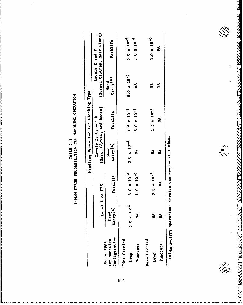
x. z
C -C 4c
IF.
.~. 0 10 0do
04.
ca 4p r-0.3 S* >0 l
* a1%464
m0
"-4 -4 -4-
o 9 4. 40 000 it4 z4-4
oa* 0 *a V v19r 0a. W4 41*"4 Ci 0 "1 0
0)- Q W 0 4)~.4 0- 4 4
I-bi C 4 w
-.- a
46-4
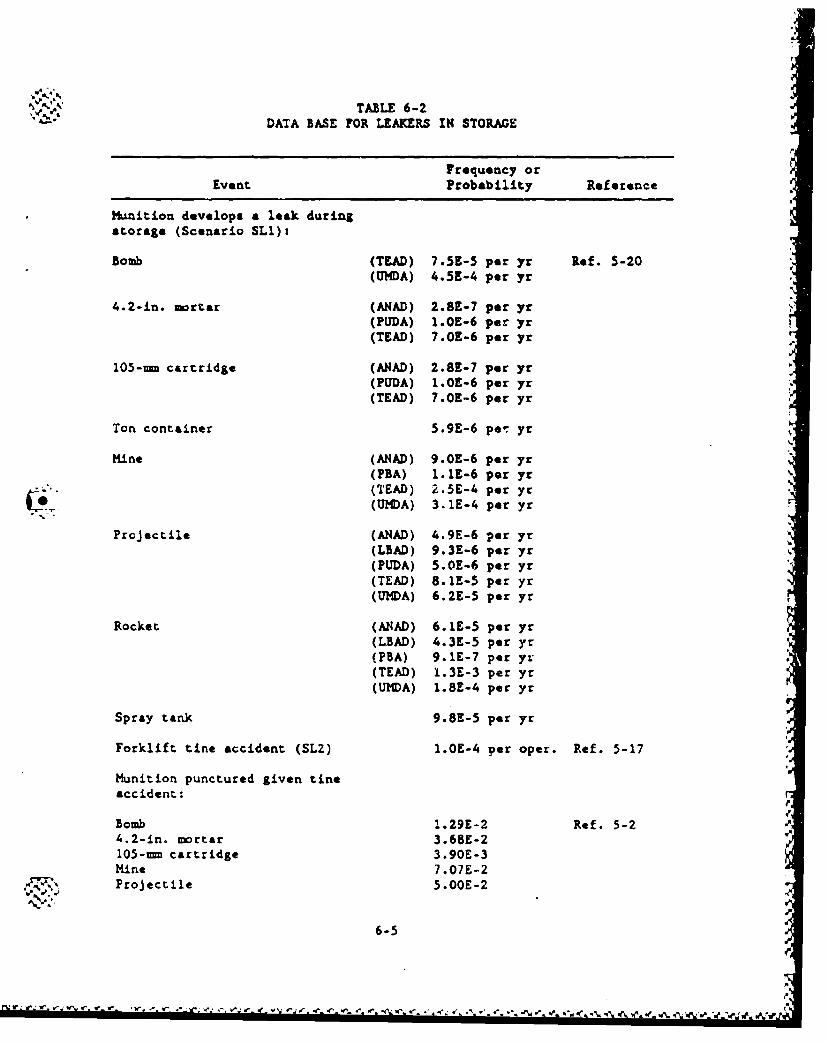
"TABLE 6-2DATA BASE FOR LEAKERS IN STORAGE
Frequency orEvent Probability Reference
Munition develops a leak duringstorage (Scenario SLI):
Bomb (TLAD) 7.5E-5 per yr Ref. 5-20(UMDA) 4.5E-4 per yr
4.2-in. mortar (ANAD) 2.8E-7 per yr(PUDA) I.OE-6 per yr(TEAD) 7.OE-6 per yr
105-mm cartridge (ANAD) 2.8E-7 per yr(PUDA) 1.OE-6 per yr(TEAD) 7.OE-6 per yr
Ton container 5.9E-6 per yr
Mine (ANAD) 9.O0-6 per yr(PBA) 1.1E-6 per yr(TEAD) 2.5E-4 per yc(UMDA) 3.1E-4 per yr
Projectile (ANAD) 4.9E-6 per yr(LBAD) 9.3E-6 per yr(PUDA) 5.OE-6 per yr(TEAD) 8.1E-5 per yr(UMDA) 6.2E-5 per yr
Rocket (ANAD) 6.1E-5 per yr(LBAD) 4.3K-5 per yr(PBA) 9.1E-7 per yr(TEAD) 1.3E-3 per yr(UMDA) 1.8E-4 per yr
Spray tank 9.8E-5 per yr
Forklift tine accident (SLZ) 1.0E-4 per oper. Ref. 5-17
Munition punctured given tineaccident:
Bomb 1.29E-2 Ref. 5-2 e4.2-in, mortar 3.68E-2105--m cartridge 3.90E-3Mine 7.07E-2Projectile 5.OOE-2
6-5
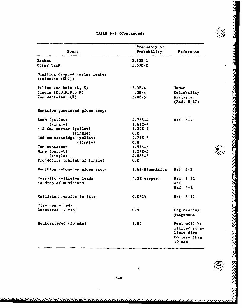
* '¾
TABLE 6-2 (Continued)
Frequency or
Event Probability Reference
Rocket 2.63E-1Spray tank 1.53E-2
Munition dropped during leakerisolation (SL9)t
Pallet and bulk (B, S) 3.0E-4 HumanSingle (C,D,M,P,Q,R) .OE-4 ReliabilityTon container (K) 3.0E-5 Analysis
(Ref. 5-17)
Munition punctured given drop:
Bomb (pallet) 4.72E-4 Ref. 5-2(single) 1.62E-4
4.2-in. mortar (pallet) 1.24t-4(single) 0.0
105-u= cartridge (pallet) 2.71E-5(single) 0.0
Ton container 1.55E-3 '
Mine (pallet) 9.27E-5(single) 4.08E-5
Projectile (pallet or single) 0.0
Munition detonates given drop: 1.6E-8lu-inition Ref. 5-2
Forklift collision leads 4.3E-6/oper. Ref. 5-12to drop of mnitions and
Ref. 5-2
Collision results in fire 0.0725 Ref. 5-12
Fire contained:Burstered (4 min) 0.5 Engineering
j udgement
Nonburstered (30 min) 1.00 Fuel will belimited so aslimit fireto less than10 min
6-6
S•t• • • "•t•,,'•/ I•.•.•r•."•'•'%•.•A .'-.-•.'• •o•.•',• @.•% s• % •.• .p,,.', =• =% '..,.==• • . ,.•o.-. o.., .. ".c ,.. .. -" .,•. '•,,," '_" ,.q%" " , '•.• ,•• .
X.N'. munition. (This puncture probability applies to those cases
in which forklift tines are used to lift munitiona; it
includes palletised uanitione and spray tanks in overpacks.)
Another difference is that the original estimate from Ref. 6-4
(4 x 10⁻⁵) was bsed on operations with leaking rockets. This
meant that it assumes that the crew is wearing Level A protec-
tive clothing. If the same forklift operations are performed
in less strenuous circumetances (i.e., if a lower level of
protective clothing is wrn), the error probability estimate
can be lowered. Here, it has been lowered to 5 x 10⁻⁵ for the
case of the operators' wearing partial protection (masks,
gloves, and boots) and to 1 x I0-5 for the case c.i rheir wear-
ing minimal protection (street clothes, with masks slung).
2. Droping a munition. For palletized manitions and spray tanks
in their overpacks, humin-caused drops from forklifts are
judged to be three times as likely as punctures caused by
"operating the same kind of forklift. The error-probability
estimates are 3 x I0-4, 1.5 x 10⁻⁵, and 3 x 10O5 for dropping
a munition from a forklift tine when wearing Level A, Level C,
or Level F protective clothing, respectively.
Because of unwieldy pallet and overpacked spray tank loads,
and because it is assumed that forklift-tin, loads are likely
to be carried at higher speeds than are forklift-beam loads,
the likelihood of a ton container or other beam-carried loads
being dropped because of human error is judged to be an order
of magnitude lower than that of a tine-carried load being
dropped. These are estimated to be 3 x 10⁻⁵, 1.5 x 10⁻⁶,
and 3 x 10.6 for protective clothing Levels A, C, and F,
respectively.
6-7
e. le.
For hand-carried munitions, munition drops are estimated to be °:-
twice as likely as drops of tine-carried load from forklifts.
The estimared probabilities of dropping a hand-carried muni-
tion when wearing Levels A, C, and F protective clothing are
6 x 10⁻⁴, 3 x i0- 4 , and 6 x 10⁻⁵, respectively. (Loads car-
ried by forklift beams are never hand carried.)
These probability estivmtes are the likelihood of an error per
handling operation. A single forklift operation may involve a
single -niition such as a spray tank or as many as 48 weapons
on a pallet, while a single hand-carry operation will always
involve only a single munition.
%.'N
A
6-8
-.
r.j. .W N-ji , ýW W.b~ . - .I
I*1_
6.3. REFERENCES J
6-1. Clarke, R. K., et a.l, OSeverities of Transportation Accidents,"
SLA-74-O01, Sandia National LaboratorLes, July 1976.
6-2. "Handbook of Human Reliability Analysis with Emphasis on Nuclear
Power Plant Applications, NUREG/CR-1278, U.S. Nuclear Regulatory
Commission, August 1983.
6-3. "Probabilities of Selected Hazards in Disposition of M55 Rockets,"
M55-CS-02, USATHAMA, Septeumber 22, 1985.
6-4. Federal Railroad Administration, "Aucident/Incident Bulletin " of
No. -151, Calendar Year 1982," Department of Transportation, June .
1983.
41
"o.
-. (
l.
6-9
SI
7. AGENT RELEASE CHARACTER•7ZATION
Section 7.1 describes the approach used in this study for analyzing
the agent release for the various accident conditions. Application of
the approach to the accident sequences analyzed in the continued storage
option is discussed in Section 7.2.
The consequences of an agent release event are strongly dependent
on agent type, amount of agent release, and the mode and duration of the
release. Agent dispersion and subsequent effects will be calculated in
a separate study using & computer program called D2PC (Ref. 7-1) that
embodies an analytical model for calculating agent dispersion under dif-
ferent meteorological conditions. Feedback from these consequence cal-
culations helped to guide the release characterization.
"7.1. RELEASE ANALYSIS APPROACH AND BASES
7.1.1. Approach
The approach formlaton was aided by a systematic review of the
mechanisms involved in expelling agent from its normal confinement. The
analyses performed by Arthur D. Little for the M155 rockets (Refs. 7-2
through 7-6) were paztially applicable, and similar assumptions as
appropriate were made for this analysis. Additional calculations were
performed in this etu'.y to determine the quantity of agent released to
the environment for plant operation accidents involving aunitions other
than the M55 rockets.
For the accident scenarios that involve agent still confined in the
manition, the agent release is dependent on the manition's mechanical
and thermal failure thresholds, and the behavior of the explosives and 4
7-1
S.
S%
propellants during the accident scenarios. These are discussed in the J% Y'
following s'ctions. Once it was determined that the agent could be " 6breleased from its -. urmal confinemint, calculations were performad to
detezrine the amount of agent released and the possible paths by which
the agent could enter the atmosphere.
7.1.2. Mechanical Failure Release
Munition failures result when sufficient forces are generated dur-
ing accidents. A discussion of the -anition failure thresholds is given
in Appendix F. The failure thresholds of interest are:
1. Mechanical failure of the agent containment due to impact,
crush or puncture.
2. Detonations initiated by impact or fire.
3. Thermally induced hydraulic rupture of the agent containment.
7.1.2.1. Impect Failure. The threshold for impact failure is given in -YO-.terms of velocity of impact against a nonyielding object, or the equiva-
lent drop height. When the impact failure threshold is reached, it is
assumed that the onset of failure begins. In the case of an accident
involving more than one munition, e.g., a pallet drop or a forklift col-
lision, every munition does not experience the effect of impacting a
nonyielding surface. At the threshold point, it is assumed that at
least one manition has experienced failure. It was further assumed that
the number of mnitions that experience failure is a function of the
kinetic energy involved in the accident.
The impact velocity required to initiate failure varies from 35 mph
for rockets (drop height of 40 ft) to 50 mph for projectiles (drop
7-2
W.A
height of 120 ft). The expected impact velocity (or drop height) forIZ.
some accidents is: .
Impact Velocity of
Accident Type Drop Height
Pallet drop during handling 6 ft
Forklift collision 5 mph
In view of the above, failure due to impact is not considered to be a
significant contribution for handling accidents, i.e., other failure
mechanisms dominate.
7.1.2.2. Crush Failure. Crush forces are static forces completely
independent of velocity. Crush forces may arise from a building
collapse due to an earthquake.
Crush thresholds are defined for a single nitition and for a pallet
£. of munitions. When the crush threshuod for pallets is exceeded, it w as•
"conservatively assumed that all umnitions in the pallet will fail.
°.4
A linear relationship for the number of units that would fail due
to crush vws assumed as follows:
FV n - F , I7-1L,-j
where F - crush force available in the accident,
FO - crush force threshold for the pelletized m•inition.
At n - 1, all the uonitions in one pallet have failed. The avail-
able force in an accident can be the weight of a vehicle, the weight of
a building collapse, or the weight of any large obJert that ct fall on
the muinitions.
7-3
i . - 'CZ../
C.
The accident scenarios that are capable of $onerazing forces suffi- %J-
ciently high to produce crush involve external events where many pallets
may be involved in the accident. Thus, it is possible that more than
one pallet can fail. For example, the crush threshold for a rocket pal-
let containing 15 rocket* is 43,400 lb. If the wsight of an object is
100,000 lb, Eq. 7-1 predicts a failure quantity of 2.3. Th-is corre-
sponds to 2.3 pellets, or about 34 rockets being crushed. If the avail-'p
able crush force is less than the failure threshold for a single m.~ni-
tion, then naturally, no manitions fail.
Equation 7-1 is conservative because it essamus that the total
available load arising from an accident is concentrated in the most
efficient way to crush the nitions. If the load was uniformly dis-
tributed over ,.any paile.;s, fewer or nn failures would occur.
7.1.2.3. Punctur(. Failure- T1,e puncture threshold As defined in terms
of tht ratio of velocity to radi-i. of curvature ass' ing the manition
(or pai.letl impacts an unyielding slender object or probe. Generally, -
the failure threshold for puncture is the lowest of the three mechanical "->.- .-
failure thresholds. The number of failtures that can occur in an acci-
dent is dependent on the number of probes present. If the puncture
failure threshold is exceeded, it is assumed that one probe will fail
one •mnition.
7.1.2.4. Liquid Spills and Evaporation. Once mechanical failure
occurs, the munition agent inventory may be able to spill out on the
ground or water. For forktine pumnctures, the puncture is assumed to
consist of a 3-in. diamter hole just below the uanition centerline.
The amount snd time of spill is calculated to be that wich can drain by
gravity out of the hole. Impact, crush and probe punctures are assumed
to result in the spill of the entire minitions inventory.
If the spill occurn outdoors during leaker handling, the release
analysis ends with the determInation of the type and mass of liquid
7-,...,j .4
7-4 .,,
,.4-
4.
&Sent spilled and type of surface where the spill occurs. This informs- %
tion is sufficient input for calculation of atmospheric dispersion by
the D2PC computer program (Ref. 7-1). All liquid spills during handling
or ground transport are assumsd to occur on a hard, flat impervious
surface such as level concrete or asphalt. The evaporation of the spill
is calculated by the D2PC program by calculating the maximam puddle area
and the corresponding evaporate rate.
If the spill occurs indoors, the release analysis in this report
extends to the time dependent rates of evaporation. In general, the CD2PC program was applied to calculate the evaporation rate based on the
type and mass of agent spill and considering any confinemnt of the
liquid puddle or pool. The D2PC general equation for evaporation of a
spill over a floor area corresponding to a liquid pool depth of 1/32 in.
relates the time t to evaporate the entire spill inventory M (pounds)
in terms of a power function of M and tw coefficients a and b. The
equat ion is
t - •Hb , (7-2) e
where t - time in thousands of minutes, J
a, b - constant for agent GB (a a 0.79, b - 0.253),
a, b - functions of M for agents H and VX.
The area (ft 2 ) corresponding to the spill M (lb) and pool thickness
1132 in. is 5.91 times M. For restricted pool areas, the equation must
be modified. This equation and coefficients a and b are based on data L.•--
from the Army derived from the computer program D2PC output.#-
For a given accident sequence the spill will generally not evepo-
rate to completion because human intervention will mitigate the spill by
covering it wtcih foam or some other mans. In such a case, an evapora- e.
tion rate is calculated and applied intil the time estimated for mitiga-
tion or cleanup of the ap!.!l. r
7-5
From Eq. 7-2, the hourly evaporation rate is
I 60 mnmmv - 1-b -(7-3)
103 min
where mev ha. units of lb/h. This equation applies whenever the
1/32-in. deep spill pool area, which from the agent density is about
6 ft 2 for each lb of spill, is smaller than the actual confined pool
area (floor or sum).
Where a sump is present, the following procedure is used to calcu-
late evaporation. Initially, the spill is assumed to wet the entire
sloped floor area. Thus, Eq. 7-3 issued for a 10 min time period with-
out modification for pool ares, unless the 1132-in. deep pool area is
larger than the actual floor area. Modification consists of limiting
H in Eq. 7-3 to the mass of a 1/32-in. layer of agent over the actual
floor area. After 10 min, the evaporation rate is asswuod to be lim-
ited by the sump horizontal cross sectional area until the assumed miti- A- -0 Igation/cleanup time when it drops to ereo. Such limitation saounts to
modifying H in Eq. 7-3 to the mass of a 1/32-in. layer in the sump.
7.1.3. Detonations
The burstered munition. incorporate proven design features to pre-
clude accidental detonation during routine handling. The imact thresh-
old for initiating detonation, approximately 160 mph (see discussion in
Appendix F), is well above the potential impact velocity for all acci-
dents. When a mnnition is subjected to an impact velocity greater than
the detonation threshold velocity, there is still a loa probability of I
detonation, but it is possible. Data does not exist to develop a mean- V_
ingful relationship for predicting the number of detonations that could
occur given an aircraft crash into a muanitions storage area. This
rationale is that, given a stack of manitions pallets in storage themunitions in the first row would absorb most of the impact energy.
These mnnitions could detonate. The others would then be subjected to
7-6 5
S
•.5
uI
the energy of the detonations, as vell &a part of the energy of the air-
craft crash. It is known that, the detonations do not propagate, but it
is assumed that many of than voald rupture. This logic me applied to
all the aircraft crash scevsrios and a general result was reac'Aed. The
conservative estimate iw that:
1. fifteen percent of the munitions involved in the crash
detonate.
2. Seventy percent of the rupture and release their agent
content.
3. Fifteta percent are scattered but remain intact.
For imacts of burstered muniticns in pallets, if a single munition
detonation occurs it is assumed to rupture each surrounding innition in
the pallet. A centrally located munition, which has the largest number
of surrounding units, is conservatively assumsd to be the one which det-
onates, even though it is less likely to detonate at this location
thanat the end. For projectiles, cartridges, and mortars, the number of
adjacent munitions ruptured is five.
For rockets and mines only, the detonation of more than one muni-tion was calculated to be credible for certain pallet impacts. In such
cases, tuo rockets detonate, rupturing 13 adjacent rockets. Or, three
mines detonate rupturing 15 adjacent maunitions.
7.1.4. Fire Release p
Munitions subject to fire can fail due to thermally in!'iated deto-
nations or due to hydraulic rupture. It is assumed that fires in direct
contact with burstered miitions will be left unattended and allomed to -
burn until all combustible materials are consumed. Thus, bursters will
detonate. Soma neighboring m-anitions will fail due t.o the detonation.
The failed munition& will spill combustible agent which will further
7-7
.%
fuel the fire. The fire will spread, loading to more detonations, and
so on.
Tests at GA on 4.2-in. mortar projectiles and 8-in. projectiles
showed that a detonation of a monition in a close packed array will
cause the munitions adjacent to the detonated menition to break and
spill their agent (Ref. 7-7). Other minitions not in direct viev of the
detonated imnition were disheveled, but remained intact. Thus, one
detonation is not sufficient to break all the mamitions involved in the
accident. A chain reaction must take place. The bursters in the neigh-
boring muitions broken by a detonation will be subjected to more rapid
heating than those of an intact munition. These bursters will detonate
at a critical temperature, but it is assumed that detonation of a
drained munition will not contribute to the agent release.
Based on the test results described above, it is inferred that all
munitions in direct view of a munition detonation would be broken. In a
rectangular array, typical for the munition storage configurations, this "j
results in an agent release fraction of 119 due to detonation and 8/9 as .L *' %
a liquid spill. An irregular array, such as would exist after the first
detonation, could result in a larger release fraction due to detona-
tions. Therefore, it is assumed that 25Z of the agent release is due
tc detonations for scenarios involving fire and detonations.
It is assumed that fires involving nonburstered munitions will
always be fought. However, when an accident involves a large fire, the
first priority may be to contain the fire and prevent its spreading into
unaffected areas. For conservatism, a large fire involving nonburstered
munitions was treated as in the case for burstered munitions, i.e., all
combustible materials involved in the accident are consumed. Whether
burstered or nonburstered munitions are involved, large fires were
assumed to be confined to one building, one railcar, or one truck, as
appropriate.
7-8
A
Agent that is burned is basically destroyed, but the destruction
is usually incomplete. A previous analysis (Ref. 7-8) indicated
that the recovery of undecomposed agent from fires is 2.5Z for GB and
0.22 for VX. Tha analysis wa based on tests at Dugmay Proving Ground
(Refs. 7-9 and 7-10) in which a mock-up Igloo with 11 pallets of rockets
containing GB was allowed to burn to r.opletton. The unburned GB vapor
was measured by a grid of detectors surrounding the fire at 30 mdistance and extending 30 a high. Actual test measurements var* made
for GB, and the results for VX were derived by extrapolation based on
the boiling temperature, thermal decomposition temperature andvolatility of VX rol"tive to GB.
Although the references cited above provide a quantitative data
point on the behavior of agent in a large fire involving an igloo or a
transport vehicle, there are several reasons to increase the predicted
agent release fraction for fires. These are:
1. The analytical procedure for detecting agent during the
test yielded small quantities of agent distributed over a
large number of detectors. The samples were analyzed by the
dianisidine-peroxide method. The sensitivity of these mea-
surements is expected to be marginal considering the short
time available for sampling the gas cloud as it passed through
the detection grid. Therefore, it Is possible that a signifi-
cant aMount of agent vapor was not detected during the test.
2. The rockets contain a large amount of propellant, which in
turn contains its own oxidizer. The propellant burns very
quickly and tends to produce a hot fire, even when the fire
is limited by the amount of oxygen present. Fires involving
other munitions may burn slower and at a lower temperature,
which would promote a higher fraction of undestroyed agent.
7-9
It,•; .• w•-."- ,,(-÷ •,• =• ,,i•-.', V ' ,,--.,-,, - , - ÷, -,,, --.. ,--ja, ÷ ,.- , ' •" " " ',"i",, \-- K•' , ', ., ,''.,,( .. , .'
)%
3. In one simulated test of an igloo fire (Ref. 7-10) four rock-
ets wtre launched out of the igloo. One of them traveled
1300 ft away from the igloo. None of them detonated upon
impact, but they all broke open and spilled agent onto the
ground. When one adds the liquid spill of the four rockets
that escaped from the igloo to the 2-1122 agent vapor recov-
ered, the total agent release from the event is 4.9%.
4. The analytical extrapolation to determine the recovery frac-
tion for VX is not documented. Further, the uncertainty of an
extrapolation in a complex tbermal-chemical rate process is
considered to be large. Although the chemical properties of
VX and GB suggest that the recovery fraction for VX should be
much less than GB, the conclusion that the recovery of VX
would be 62 times the recovery of GB as stated in Ref. 7-10 is
viewed with skepticism. Therefore, a more conservative value
of 252 was assumed for the recovery factor of VX versus GB.
Similarly, the chemical properties of HD suggest that an ana-
lytical extrapolation for the recovery of RD would also be
less than G5, but greater than VX. Therefore, a value of 50%
was assumed for the recovery factor of HD versus GB.
In view of the above discussion, the release fraction for unburned
agent GB vapor in all fire scenarios wa assumed to be 102. This pro-
vides a factor of tw over the 4.9% combined liquid plus vapor measured
in the test to allow for uncertainties in the test measurements and
uncertainties in the liquid agent that escapes the fire. The corres-
ponding release fractions for RD and VX are assumed to be 51 and 2-1/21,
respectively. These release fractions are not considered as over con-
servatism. The main conservatism arises from the assumption that all
the agent inventory is involved in the fire, and no credit is taken for
the possibility that the fire might be extinguished before all combusti-
ble materials are consumed.
7-10 PIN
? .~~ 4 ~qJ.g 'i'~y~.*
7.1.5. Release Duration
The accident durations assumed for this risk analysis mere chosen
to conservatively define a time for terminating meot accidents identi-
fied in this analysis. In the scenarios involving liquid spills, the
accident is terminated when the decontamination team has successfully
terminated evaporation of agent vapor into the atmosphere. Army experi-
ence in handling and moving chemical munitions indicates that may of the
agent spills could be cleaned up much quicker than the times assumed
herein. However, since many accidents are rate events and have not
occurred in the Army experience to date, conservative times for the
accident durations have been applied.
The agent release for an evaporative spill is directly proportional
to the release duration. Therefore, to be conservative, the release
durations vere estimated on th- high side. The release durations
assumed ares
1. For agent spills occurring during handling caused by human or
equipment malfunction, the release duration was assumed to be
1 h.
2. For agent spills arising from an aircraft crash with no fire,
the release duration was assumed to be 4 h. ".
3. For severe external events, e.g., earthquake, tornado, air-
plane crash, the evaporation time was assumed to be 6 h.
Table 7-1 lists the times assumed for agent release for the acci-
dent scenarios involving fire andlor detonations.
The approach to deriving the assumed release durations was to group
the accident scenarios with fire or detonations into sets with similar e.
characteristics, then estimate a release time ranging from 10 min to
7-11
V.e *V. -
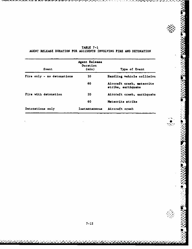
Ib
TABLE 7-1AGENT RELEASE DURATION FOR ACCIDENTS INVOLVING FIRE AND DETONATION -
Agent Release IN.
DurationEvent (min) Type of Event
Fire only - no detonations 10 Handling vehicle collision
60 Aircraft crash, meteoritestrike, earthquake
Fire with detonation 20 Aircraft crash, earthquake
60 Meteorite strike
Detonations only Instantaneous Aircraft crash
.4.
'p.
. . le
7-12
... * .. .. . . . . .
*%•
1 h. For accidents involving a large fire, it was assumed that all of
the agent present ultimately becomes consumed or released as vapor. The
conservative approach for these caes to to assume a shorter duration
than expected because a given release to the atmosphere is more lethal
when distributed over & shorter time interval. Factors which influence
the choice of time periods are discussed below.
There are three possible combinations of scenarios involving fire
and/or detonations'
1. Detonations only.
2. Fire and detonations.
3. Fire only.
7.1.5.1. Detonations Only. The scenarios that fall into this category
involve a high velocity imact, such as an aircraft crash, or spurious
detonation arising from undue forces that are part of the accident ace-
nario, e.g., dropping a pallet. It is known that the detonations do not
propagate. Therefore, the release from detonations is assumed to occur
instantaneously.
7.1.5.2. Fire and Detonations. These events are associated with exter- rnal storage accidents. For some events, there is a source of external
fuel, e.g., an airplane crash. In these scenarios, the detonations are
propagated by the fire, and concurrently the detonations allow
additional -munition failures that further fuel the fire. The overall
result is a violent conflagration. The total duration of the accident
may be an hour or more; however, for conservatism, the duration of the
agent release is assumed to be 20 min. The scenarios not included in
the 20-min assumption involve a meteorite strike into a storage igloo or
into a temporary storage area. In this case, there is no source ot
external fuel, although the scenario does assume that fire is initiated,
and detonations are propagated by the fire until all combustible
materials are consumed. Because the meteorite tire *tarts out
7-13
A!.
r. 61 6- )- 60 d - '_I. ~ -ýA F- r- tr 'r ~ . WV W'. W'-. . W. V-r -W% W.~ . ý. WJr V' .. M %,q*
4.,
relatively localized and without external fuel, the release duration for
the meteorite strike is assumed to be 1 h.
7.1.5.3. Fire Only. Events involving fire only occur in some storage
accidents. For events associated with handling the amount of agent
involved in the fire is relatively small. The e"posed agent is allowed
to burn to completion, and the release duration is assumed to be 10 min.
Accidents involving external events involve large quantities of agent.
Therefore, these accidents present a less diffLcult situation to con-
trol. The agent release duration for these events was assumed to be
1 h . 1 '
a.•i
.4. |..
I..,
!-%
7-14
A ý'..,7: L( '.Cý
a ~ V * 'a ''~ ''4.'.
-- AAr~ -. - 11 -A N IM. .- -. .-
7.2. APPLICATION TO ACCIDENT SEQUENCES
I
This section illustrates the application of the release methodology
to determine agent releases for the specific accident sequences. It is
not intended to ancompss all sequences. Appendix I presents the agent
releases for all sequences. Table 7-2 gives the munition and pallet
inventories. Details of all agent release calculations are contained in
the supporting calculations for this risk assessment, Ref. 7-11.
7.2.1. Warehouse Storasg Release Durina Earthquakes -
There are three sites with stored, nonburstered -naitions in ware-
houses. These arot
1
1. WNA - ton containers with agent HD stored in tw* warehouses.
%2. NAAP - ton containers with agent VI stored in one warehouse.
"3. TEAD - spray tanks with agent VX stored in tw warehouses.
Only spray tanks and ton containers are stored in warehouses, none
of which contain agent GB. Based on their impact characteristics, the
ton containers are predicted to be able to be crushed or breached by the
kinetic energy of a falling I-beam if the warehouse structure is dam-
aged. Each I-beam has sufficient energy to crush one ton container but
not tw. Thus, the maxi-im number of ton containers crushed per ware-
house is five, since there are that many I-beam in the warehouse roof.
For similar reasons, the maximum, number punctured is taken to be five
per warehouse.
Spray tanks are stored in overpacks and, based on structural
calculations, are not expected to be breached by the falling I-beams.
7-15
%l-- S. *~ *
• - ••- . . . . •, . .. . . .. •. . .. . -. . , .. ., .,, . .- .... .. . .. . .. . .. . •. .. .. . .. .. .. . .. . . . .,. . ,. . .,, . -, ,',
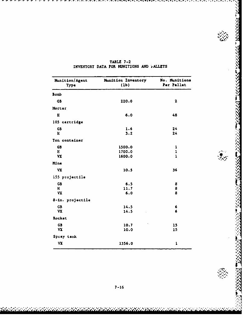
u-. i V . or'. w. . V- %-. - V. -r- - Cý V V. U'% fA W~. W. W WJ '.
TABLE 7-2INVENTORY DATA FOR MUNITIONS AND iALLETS
Yrunition/Agent Munition Inventory No. MunitionsType (lb) Per Pallet
Bomb
0B 220.0 2
Hortar
H 6.0 48
105 cartridge
GB 1.6 24H 3.2 24
Ton container
GB 1500.0 1H 1700.0 1 -VX 1600.0 1
Mine
vx 10.5 36 ,
155 projectile
GB 6.5 8H 11.7 8Vx 6.0 8
8-in. projectile
GB 14.5 6Vx 14.5 6
Rocket
GB 10.7 15Vx 10.0 15
Spray tank
VX 1356.0 1
7-16
* ..........
Consequently, the mechanical breaching of spray tanks due to an Garth-
quake is not considered a credible event. If a fire lasts beyond
30 min, spray tanks may fail due to the unsuppressed fire. Thus, for
spray tanks, only one type of release is considered, namely burning of
one or two warehouse inventories due to fire beyond 30 min. The release
fraction due to unburnt VX agent in this case is Z.52, as in other acci-
dent scenarios.
For ton containers, three release types were considereds
1. Evaporation of agent spilled due to mechanical breach of one
to five containers per warehouse.
2. Burning of agent spilled from breached containers.
3. Burning of the entire inventory in the warehouse, starting at
30 sin.
The evaporative release rate is not limited by the floor area,
which is tens of thousands of square feet per warehouse. Thus, the
evaporative release rate, mev, is given by Eq. 7-2. For 10-ton con-
tainers with agent ED, M - 17,000 lb and a 0 451 and b 00.1. Thus,
y- 0.85 lb/h for 10 containers. This rate of HD release is negligi-
ble. Therefore, evaporative release of spilled HD from breached -ini-
tions is negligible. For agent VX, the maxi--, number of breached ton
containers is five. In this limiting case, M m 8000 lb and a N 49,000,
b U 0.12. Thus, mev - 0.003 lb/h for five breached containers. This
rate of release is negligible.
The second and third types of releases involve burning of spilled
agent from breached containers or burning of all ton containers due to a
lack of fire suppression. For these cases, the release consists of the
product of the appropriate inventory and the fire release fraction, F.
Here, F - 0.025 for agent VX and F - 0.05 for agent HD, consistent with
7-17
"'.'r r W I -',. -r 0 C r
L .P . ..... A~. A~.......
data described above. No credit is taken for agent vapor retention by
the warehouse building, even if it is not structurally damaged by the
earthquake, becauas it is not designed with a containment function.
As described in Section 5, an event tree was analyzed for the stor-
age of ton containers at the UMA and NAAP site warehouses. For the
UIDA site, there were 17 release sequences with frequencies above
10'10/yr. Tabl* 7-3 lists these sequences along with the information
pertinent to the release calculations. For sequences in which the burn-
ing or agent spilled from breached maunitions is the only release mode, a
range of release is given corresponding to the range of containers
breached (1 to 5 or 2 to 10). For sequences in which the nonsuppressed
fire ignites the entire warebouse inventory, the number of breached
containers is unimportant.
Table 7-4 presents the corresponding release results for ton
containers stored at the NAAP site. Only five sequences are important
since there is only one warehouse at the site. The maximam masses of
agent VX released from this site are seven times lower than mazi-am mass
releases if agent HD from UZDA.
In the event tree for spray tanks stored at the TEAD site, there
were six significant sequences as given in Table 7-5. Since no spray
tanks are mechanically breached, the only consequence variable is
whether the unsuppressed fire is not suppressed in one or both ware-
houses. The releases upon burning of the entire inventory at one or
both warehouses are given in Table 7-5. They are 8 to 16 times lower
than the maximum release of the a&= agent (VX) from the HAAP site.
7.2.2. Uncertainties
No uncertainty analysis was performed for the agent release anal-
ysis. The releases reported are treated as conservative estimates,
rather than central estimates, since they are based on assumptions which
7-18
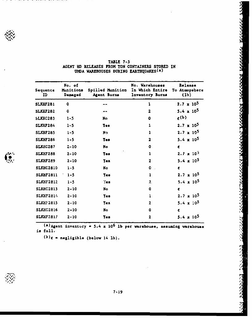
TABLE 7-3AGENT HD RELEASES FROM TON CONTAINERS STORED IN
UMDA WAREHOUSES DURING EARTHQUAKES(a)
No. of No. Warehouses ReleaseSequence Munitions Spilled Mia-4tion In Which Entire To Atmopshere
ID Damaged Agent Burns Inventory Burns (lb)
SLKHF281 0 -- 1 2.7 x 10⁵
SLKRF282 0 -- 5.4 105
SLKHC283 1-5 No 0 e(b)
SLKHF284 1-5 Yes 1 2.7 x 10⁵
SLKHF285 1-5 No 1 2.7 x 10⁵
SLKKH286 1-5 Yes 2 5.4 x 10⁵
SLKHC287 2-10 No 0 e
SLKHF288 2-10 Tee 1 2.7 x 10³
SLKHF289 2-10 Yes 2 5.4 z 105
SLKHC2810 1-5 No 0 C
SLKHF2811 1-5 Yes 1 2.7 • 105
SLKHF281Z 1-5 2 5.4 • 105
SLKHC2813 2-10 No 0 C rSLKHF2814 2-10 Yes 1 2.7 x 10⁵
SLKHI'2815 2-10 Yes 2 5.4 x z05
SLKHC2816 2-10 No 0 eSLKHF-817 2-10 Yee 2 5.4 x 10⁵
()Ag*ent inventcry - 5.4 a 106 lb per warehouse, assuming warehouseis full.
(b)e - negligible (below 14 lb).
71
I:.-
7-19 "-.
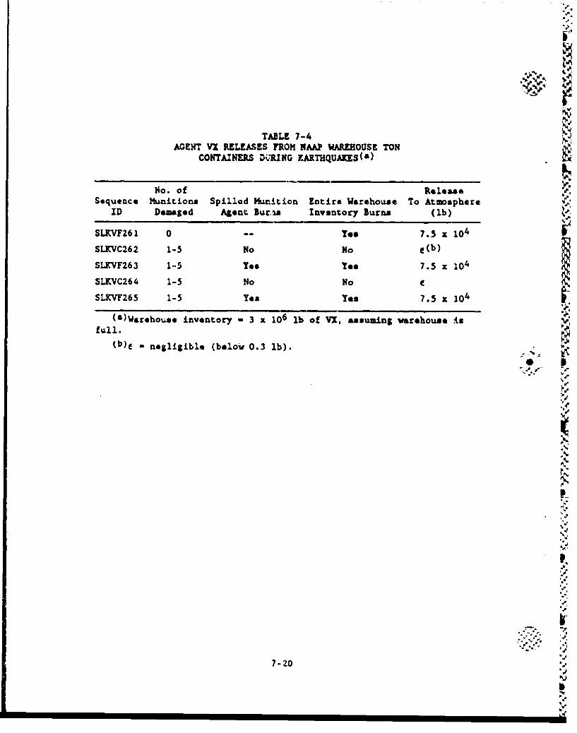
TABLE 7-4AGENT VX RELEASES FROM NAAP WAREHOUSE TON
CONTAINERS D•RING KARTHQUAKES(&)
No. of Role&&*Sequence Munitions Spillad Munrition Entire Warehouse To Atmosphere
ID Damaged Agent Bur.-%& Inventory Burns (lb)
SLKVF261 0 -- Too 7.5 x 10 4
SLKVC262 1-5 No No C(b)
SLKVF263 1-5 Teo Yes 7.5 x 10⁴
SLKVC264 1-5 No No
SLKVF265 1-5 Yet Yes 7.5 X 10⁴
(&)Warehouse inventory - 3 x 10⁶ lb of VI, assuming varehouse Is
full.(b)• - negligible (below 0.3 lb).
V.'..
7-20'
IV
*9,rT
9,,
II,
-p
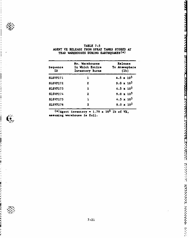
TABLE 7-5AGENT VX RELEASE FROM SPWAX TANKS STORED AT
TEAD WAREHOUSES DURING UI&RTHQUAKES(s)
No. Warehouses RoleaseSequence In Which Entire To Atmosphere
ID Inventory Burns (lb)
SLSVF271 1 4.5 z 10 3
SLSVF272 2 9.0 x 10³
SLSVI273 1 4.5 x 10³
SLSVF274 2 9.0 z 103
SLSVF275 i 4.5 x 10 3
SLSVP276 2 9.0 x 10³
()Agent inventory m 1.79 z 105 lb of VX,
assuming varehouse is full.
7-21
are often conservative. Examples ares (1) use of early thresholds of
mnition failure relative to the data (Appendix F), (2) worst-case num-
ber of adjacent manition ruptures for a munition detonation in a pallet,
(3) use of maximu rather than average inventories, and (4) upper bound
fire release factors, relative to the data.
7-22
S..
U,2
6-
°•.-
73 REFERENCES
7-1. Whitacre, C. G., et al., "Personal Computer Program for Chemical
Hazard Prediction (D2PC), U.S. Army AMC Report CRDEC-TR-87021,
January 1987.
7-2. Arthur D. Little, Inc., MAnalysis of Risks Associated with
Operation of Onsite M55 Rocket Demilitarization Plans,6 U.S. Army
Toxic and Hazardous Materials Agency, M55-OD-3, Hay 1985.
7-3. Arthur D. Little, Inc., "Analysis of Risks Associated with
Operation of the JACADS H55 Rocket Demilitarization Plant," U.S.
Army Toxic and Hazardous Materials Agency, M35-OD-9, May 1985.
7-4. Arthur D. Little, Inc., "Analysis of Converted M55 Rocket
Demilitarization Plant at Pine Bluff Arsenal,* U.S. Army Toxic
and Hazardous Materials Agency, M55-OD-10, May 1985.
7-5. Arthur D. Little, Inc., "Analysis of Risks Associated with
Operation of the CAH)S M55 Rocket Demilitarization Plant," U.S.
Army Toxic and Hazardous Materials Agency, M55-OD-11, May 1985.
7-6. Arthur D. Little, Inc., "M55 Rocket Separation Study,* U.S. Army
Toxic and Hazardous Materials Agency, H55-OD-08, November 1985.
7-7. "Design Development Test Resultas Cryo-Pretreatment System
Explosive Propagation Tests," GA Technologies Inc. Report 908644,
February 1986.
7-8. "Black Hills Army Depot Hazard Classification Tests, USATECOM
Project 5-3-0135-03," Disposition Form, STEDP-TO, Test Division,
Dugway Proving Ground, Dugway, Utah, to Chief, Test Design and
Analysis Office, DPG, June 3, 1966.
7-9. *Risk/Hazard Analysis for Hypothetical Accident/Incident at
Selected Locations Along the CONUS Shipment Route for Project Red
Hat," U.S. Army hunitions Cowmand Operations Research Group
Report 42, March 1970.
7-10. Taylor, W. T., and F. J. Hassaro, 'Hazard Classification Tests of
Igloo Storage of GB-VI-Filled M55 Rockets," Department of the
Army, Dugway Proving Ground Data Report (DPGDR)C505, USATECOM
Project 5-3-0135-02, April 1966.
7-23
"h
7-11. "Supporting Calculations for the Risk Analysis of the Disposal of _
Continued Storage of Chemical Miuitlons," GA Technologies Inc..I
EPS-GA/DP-0092 (Issue 2), Volumes 1, 2, and 3, August 1987.
p7-
6
'p.-
'p.-
- -
I..
•--
'.4..
8. RESULTS
The analysis of the potential for agent release to the atmosphere
from accident scenarios related to the continued storage alternative
included storage and handling activities. This section discusses some
of the accident probability and agent release results associated 'with
these activities.
The results of the analysis of the various activities encompassing
the continued storage alternative cannot be presented in the same units,
i.e., annual frequencies, because of the possible divulgence of clas-
sified information. This is only possil le for soma storage accident
scenarios. For accident scenarios related to the handling activities,
* the unclassified portion of the probabilistic analysis is given in terms
of frequency of accidents per pallet of munitions (or as a container of
munitions).
The evaluation of the actual risk to the public and environment
requires agent dispersion calculations which are not in the scope of the
study reported here. Despite thlis limitation, the results discussed
herein still provide useful insights on the contributions of the various
disposal activities to the risk of an agent release. These insights are
discussed below.
8.1. ACCIDENT SCENARIOS DURING STORAGE
The continued storage alternative requires some storage of muni-
tions in their existing location.
""8!P.,
8o\ 4.
.,. p.*4oi
8.1.1. Internal Events
There were no significant internal event initiators of accidents
during storage. Per unit operation, forklift drop accidents occur more
frequently than forklift tine punctures. Also, the use of a lifting
beam instead of a tine leads to an order of magnitude decrease in drop
frequency.
8.1.2. External Events
These events involve accidents caused by natural phenomena or human
activity affecting munitions in storage igloos, open storage areas,
holding areas, or warehouses. If these are assumed to be full of
munitions, the agent inventories range up to 100, 200, 1000, and 2000e. tons, respectively, for storage igloos, holding areas, open areas, and
"warehouses. The most frequent external accidenLs having significant
release involve mild intensity earthquakes or stall airplane crushes
(order depending on site). Amounts of available agent inventories
released in these events are on the order of fractions of one percent or
less (munition punctures, drops, etc.).
The largest releases occur for a large aircraft crash, a meteorite
strike, or a severe earthquake, especially when a warehouse (at MAAP,
TEAD, or UMDA) is involved. These can result in up to 10 percent of
the agent inventory released for scenarios involving a fire which has
the potential (duration) for destroying the entire inventory of an igloo
or warehouse. The munitions stored in warehouses contain only VX or
mustard which have much slower evaporation rates than GB and hence are
not easily dispersed into the atmosphere. Thus, warehouse scenariou
involving only spills are not significant risk contributors. The ware-
house at UMDA has the potential for the largest release. Meteorite
strike-initiated sequence median frequencies are one to two orders of
magnitude lowe&, than the aircraft crash-induced sequence frequencies,
As expected, munitions stored outdoors are generally more susceptible to
8-2
large aircraft crashes than Lhose stortd in warehouses or igloos, but
releases are lower. Both APG and PBA have ton containers stored out-
doors, and the aircraft crash probabilities at the** sites are somewhat
higher than at the othez sites. Igloos appear to provide only minimal
protection from direct crashes of large planes, but releases are an
order of magnitude lower. The releases are more severe if burstered
munitions are involved.
r
8-3 4
7.
8.2. ACCIDENT SCENAP'OS DUJRING HANDLING *"
Included in the handling analysis are single munition or pallet
movements by hand, forklift, or other equipment.
The results indicate that dLopped munitions, whether in pelletized
form or not, occur more frequently than either forklift tin* puncture or
forklift collision accidents. In fact, the frequency of forklift colli-
sion accidents which lead to the munitions falling off the forklift is
an order of magnitude lower than the drop accidents. Farthermore, the
type of clothing an operator is wearing while handling these munitions
infiuent* the drop frequency value. An operator wearing Level A cloth-
ing is more likely .;c commit an error that would cause the munition to
be dropped than when he is wearing more comfortable clothing.
For bare munitions, the rockets seem to be the most prone to punc-
tuxes from drops or forklift tine accidents..
Bulk items that are punctured lead to larger releases than othermunitions such as projectiles or rockets. Bombs are of concern because
they contain GB which evaporates more readily than the other agent
types. The agent vapor releases range up to 170 lb (thermal failure of
all munitions in a pallet).
Handling accidents which lead to significant agent releases (in
particular, agent GB) are dominant risk contributors because of the
relatively higher annual frequency values. Of course depending on the
actual munition inventory, the value of annual frequency may either
increase or decrease when converted to the more meaningful per stockpile
basis.
8-4.
8.3. UNCERTAITIES IN THE ANALYSIS
In assessing the risks associated with the CSDP alternatives, every
effort was made to perform best-estimate analyses, i.e., arealistic"le
evaluation and quantification of the accident sequence frequencies and
associated agent releases. The use of pessimistic or conservative
modeling techniques or data for quantification violates the intent of
the probabilistic nature of the study. Realistic modeling and quanti-
fication permits a balanced evaluation of risk contributors and compari-
son of alternatives. However, for realistic or best-estimate calcula-
tions, the obvious concern is the accuracy of the results. Uncertainty
analysis addresses this concern.
8.3.1. Sources of Uncertainty
Since the event sequences discussed in Section S.3 have not
actually occurred, it is difficult to establish the frequeucy of thesequence and associated consequences with great precision. For this
reason, many parameters in a risk assessment are treated as probabilis-
tically distributed parameters, so that the computation of sequence fre-
quencies and resulting consequences can involve the probabilistic combi-
nation of distributions.
There are three general types of uncertainty associated with the
evaluations reported in this document: (1) modeling, (2) data, and
(3) completeness.
There exist basic uncertainties regarding the ability of the vari-
ous models to represent the actual conditions associated with the
sequence of events for the accident scenarios that can occur in the
storage and disposal activities. The ability to represent actual phe-
nomena with analytical models is always a potential concern. The use of
fundamental models such as fault trees and event trees is sometimes sim-
plistic because most events depicted in these models are treated as
8-5
- .. - - -. . . . . . - . . . . . .
loading to on* of two binary states: success or failure (i.e., partial
successes or failures are ignored). Model uncertainties are difficult
to quantify and are addressed in thip study by 1*gittmate efforts of the
analysts to make the models as realistic as possible. Where such real-
ism could not be aeaieved, conservative approaches wer• taken.
No uncertainty from oversights, error*, or omission from the models
used (e.g., *vent troop and fault troess) is included in the uncertainty
analysiv results. Including these uncertainties is beyond the state-of-
the-art of present day uncertain~y analysis.
P
The nceotaintwes in the statsinent os event probabilities (e.g.,
component failure rates and onrtiat.ng event frequencies) are of two
types: intrinsic variability and lack of knowledge. An example ofintoqnsac tirf ability is thst whern thi studyablegitimate efdata is for
a population of similar components in similar environments, but not allthe components exhibit the asm reliability. Intrinsic variations can N
be caused, for example, by different ianupacturers, mrinten.c prac-
tices, or operating conditions. A second example of intrinsic variabii-
iay is that related to the nffects of long-term storage on the sondition
of the muni-tons as compared to their oris.nal configuration. Lack of
knoTledge uncertainty is associated with cases where the model parameter
is nom a random or fluctuating variable, but the analyst simply does not
knowtwhit the value of the parameter should be. Both of these data
uncertainty types v a e encountered in this study.
8.3.2. Uncertainties
The sequence frequency results discussed in this report are pre-
sentsd in term of a median value and e rang* factor of a probability
distribution reprlaenting the frequency of interest. The rangeh factor
represents the ratio of the 95th percentile value of frequency to the
50th percentile (i.e., median) value of frequency. The uncertainty in
the sequence frequency is determened using the STADIC-2 program
8-6
8-6 ~
(Ref. 8-1) to propagate the uncertainties associated with each of the
events in the fault trees or event trees through to the end result.
Some scenarios, such as those associated with tornado missiles and low-
impact detonations have rather large uncertainties. The difficulty wi` i
tornado-generated missiles lies with the difficulty in accurately model-
ing the probability that the missile will be in the proper orientation
to penetrate the munition and in predicting the number of missiles per
square foot of wind. The difficulty with the low-impact detonations
lies with the sparse amount of data available and its applicability to
the scenarios of interest. In general, uncertainties tend to be large
when the amount of applicable data is small and vice versa.
8-7I
S.9
I,o
I..-- 'S.-
8-7'
* * A K A S 5 A ' * W '5-s. V*' "U ~ - 'W - - t *.*t s -- - - - -- S d"d* •
8.4. REFERENCES _
8-1. Koch, P., and H. E. St. John, OSTADIC-2, A Computer Program for
Combining Probability Distribution," GA Technologies Inc.,
GA-A16277, July 1983.
rSD
-..
1*
-b8-
wa
II% . . . .. . .
APPEKDIX AREFERENCE LIST OF ACCIDENT SEQUENCES
I,.
%1
,?W*
B..,'
V..i
A.1. REFERENCE LIST OF ACCIDENT SEQUENCES
A reference list of accident sequences is presented here. Accident
* sequences related to storage are presented first followed by handling
activities related to surviellance and maintenance. The sequences can
be identified by the coding scheme presented in Section 4 of this docu-
ment. Following the sequence ID, a brief description of the accident is
given along with an indication as to whether or not the sequence was
corsidered for further analysis. The bases for scenario screening are
provided in the logic model section, Section 4, of the main body of this
report.
J1
iV.
.%- -1
'.4 .- ""
s)d
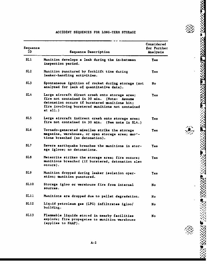
ACCIDENT SEQUENCES FOR LONG-TERM STORAGE %
ConsideredSequence for Further
ID Sequence Description Analysis
SLi Munition develops a leak during the in-between Yesinspection period.
SL2 Munition punctured by forklift tine during Yesleaker-handling activities.
SL3 Spontaneous ignition of rocket during storage (not Noanalyzed for lack of quantitative data).
SL4 Large aircraft direct crash onto storage area; Yesfire not contained in 30 min. (Notet Assumedetonation occurs if burstered munitions hit;fire involving burstered munitions not containedat all.)
SL5 Large aircraft indirect crash onto storage area; Yesfire not contained in 30 min. (See note in SL4.)
SL6 Tornado-generated missiles strike the storage Yesmagazine, warehouse, or open storage area; w -w4-tions breached (no detonation).
SL7 Severe earthquake breaches the munitions in stor- Yes •"age igloos; no detonations.
SL8 Meteorite strikes the storage area; fire occurs; Yes %k
munitions breached (if burstered, detonation alsooccurs).
SL9 Munition dropped during leaker isolation oper- Yes Iation; munition punctured.
SL10 Storage igloo or warehouse fire from internal No .
sources.
SLil Munitior.s are dropped due to pallet degradation. No
SL12 Liquid petroleum gas (LPG) infiltrates igloo/ Nobuilding.
SL13 Flanmable liquids stored in nearby facilities Noexplode; fire propagates to munition warehouse(applies to NAAP).
S Iv
A- 2 %Iw
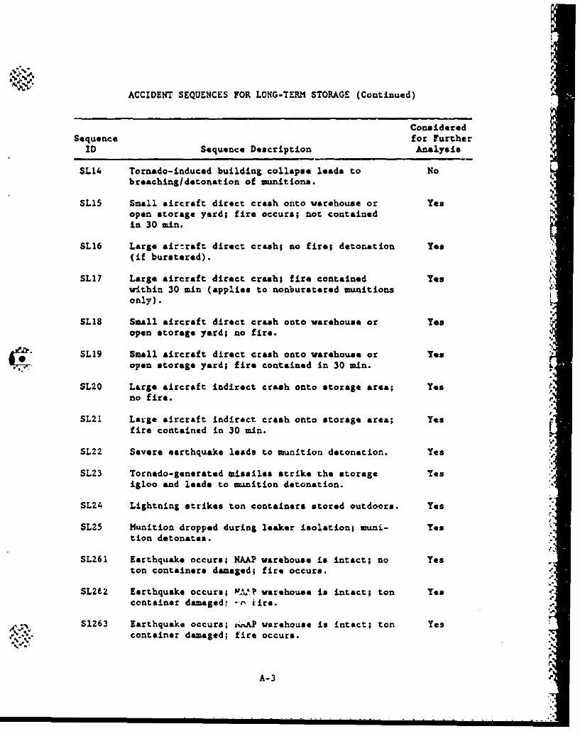
ACCIDENT SEQUENCES FOR LONG-TERM STORAGE (Continued)
ConsideredSequence for Further
ID Sequence Description Analysis
SL14 Tornado-induced building collapse leads to Nobreaching/detonation of munitions.
SL15 Small aircraft direct crash onto warehouse or Yesopen storage yard; fire occurs; not containedin 30 mi.
SL16 Large airtraft direct crash; no fire; detonation Yes(if burstered).
SL17 Large aircraft direct crash; fire contained Yes r.within 30 min (applies to nonburstered munitionsonly).
SL18 Small aircraft direct crash onto warehouse or Yesopen storage yard; no fire.
"SL19 Small aircraft direct crash onto warehouse or yes"open storage yard; fire contained in 30 min.
SL20 Large aircraft indirect crash onto storage area; Yesno fire.
SL21 Large aircraft indirect crash onto storage area; Yesfire contained in 30 min.
SL22 Severe earthquake leads to munition detonation. Yes
SL23 Tornado-generated missiles strike the storage Yesigloo and leads to munition detonation.
SL24 Lightning strikes ton containers stored outdoors. Yes
SL25 Munition dropped during leaker isolation; muni- Yestion detonates.
SL261 Earthquake occurs; NAAP warehouse is intact; no Yeston containers damaged; fire occurs.
SL262 Earthquake occurs; IJA..P warehouse is intact; ton Yescontainer damagedr --e' tire.
S1263 Earthquake occurs; týAP warehouse is intact; ton Yescontainer damaged; fire occurs.
A-3
................................................................... o..... .
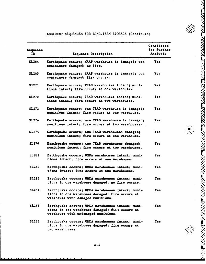
ACCIDENT SEQUENCES FOR LONG-TERM STORAGE (Continued)
ConsideredSequence for Further
ID Sequence Description Analysis
SL264 Earthquake occurs; NAAP warehouse is damaged; ton Yescontainers damaged; no fire.
SL265 Earthquake occurs; NAAP warehouse is damaged; ton Yescontainers damaged; fire occurs.
S1271 Earthquake occurs; TEAD warehouses intact; mini- Yestions intact; ftire occurs at one warehouse.
SL272 Earthquake occurs; TEAD warehouses intact; muni- Yestions intact; fire occurs at two warehouses.
SL273 Earthquake occurs; one TEAD warehouse is damaged; Yesmunitions intact; fire occurs at one warehouse.
SL274 Earthquake occurs; one TEAD warehouse is damaged; Yesmunitions intact; fire occurs at two warehouses.
SL275 Earthquake occurs; two TEAD warehouses damaged; Yes ½';munitions intact; fire occurs at one warehouse.
SL276 Earthquake occurs; two TEAD warehouses damaged; Yesmunitions intact; fire occurs at two warehouses.
SL281 Earthquake occurs; UMDA warehouses intact; muni- Yestions intact; fire occurs at one warehouse.
SL282 Earthquake occurs; UMGA warehouses intact; muni- Yestions intact; fire occurs at two warehouses.
SL283 Earthquake occurs; UMDA warehouses intact; muni- Yestions in one warehouse damaged; no fire occurs.
SL284 Earthquake occurs; UMDA warehouses intact; muni- Yestions in one warehouse damaged; fire occurs atwarehouse with damaged munitions.
SL285 Earthquake occurs; UMDA warehouses intact; muni- Yestions in one warehouse damaged; fizt occurs atwarehouse with undamaged munitions.
SL286 Earthquake occurs; UMDA warehouses intact; imuni- Yestions in one warehouse damaged; fire occurs at A,two warehouses. ;,..-.. •
A-41
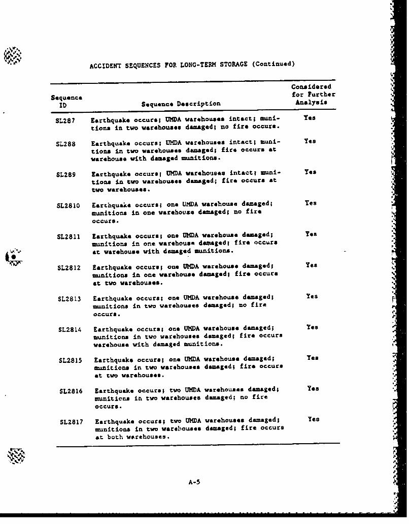
%h
"ACCIDENT SEQUENCES FOR LONG-TERM STORAGE (Continued)
Considered
Sequence for Further
ID Sequence Description Analysis
SL287 Earthquake occurs; UMDA warehouses intact; muni- Yes
tions in two warehouses damaged; no fire occurs.
SL288 Earthquake occurs; UMDA warehouses intact; muni- Yes
tions in two warehouses damaged; fire occurs at
warehouse with damaged munitions.
SL289 Earthquake occurs; UMDA warehouses intact; muni- Yes
tions in two warehouses damaged; fire occurs at
two warehouses.
SL2810 Earthquake occurs; one UZDA warehouse damaged; Yes
munitions in one warehouse damaged; no fire
occurs.
SL2811 Earthquake occurs; one UMDA warehouse damaged; Yes
munitions in one warehouse damaged; fire occurs
at warehouse with dmmaged munitions.
SL2812 Earthquake occurs; one UnDA warehouse damaged; Yesmunitions in one warehouse damaged; fire occursat two warehouses.
SL2813 Earthquake occurs; one UNDA warehouse damaged; Yes
munitions in two warehouses damaged; no fireoccurs.
SL2814 Earthquake occurs; one UHDA warehouse damaged; Yes
munitions in two warehouses damaged; fire occurswarehouse with damaged munitions. ,"
SL2815 Earthquake occurs; one UMDA warehouse damaged; Yes
munitions in two warehouses damaged; fire occurs
at two warehouses.
SL2816 Earthquake occurs; two UMDA warehouses damaged; Yes
munitions in two warehouses damaged; no fireoccurs.
5L2817 Earthquake occurs; two UHDA warehouses damaged; Yes
munitions in two warehouses damaged; fire occursat both warehouses.
A-5
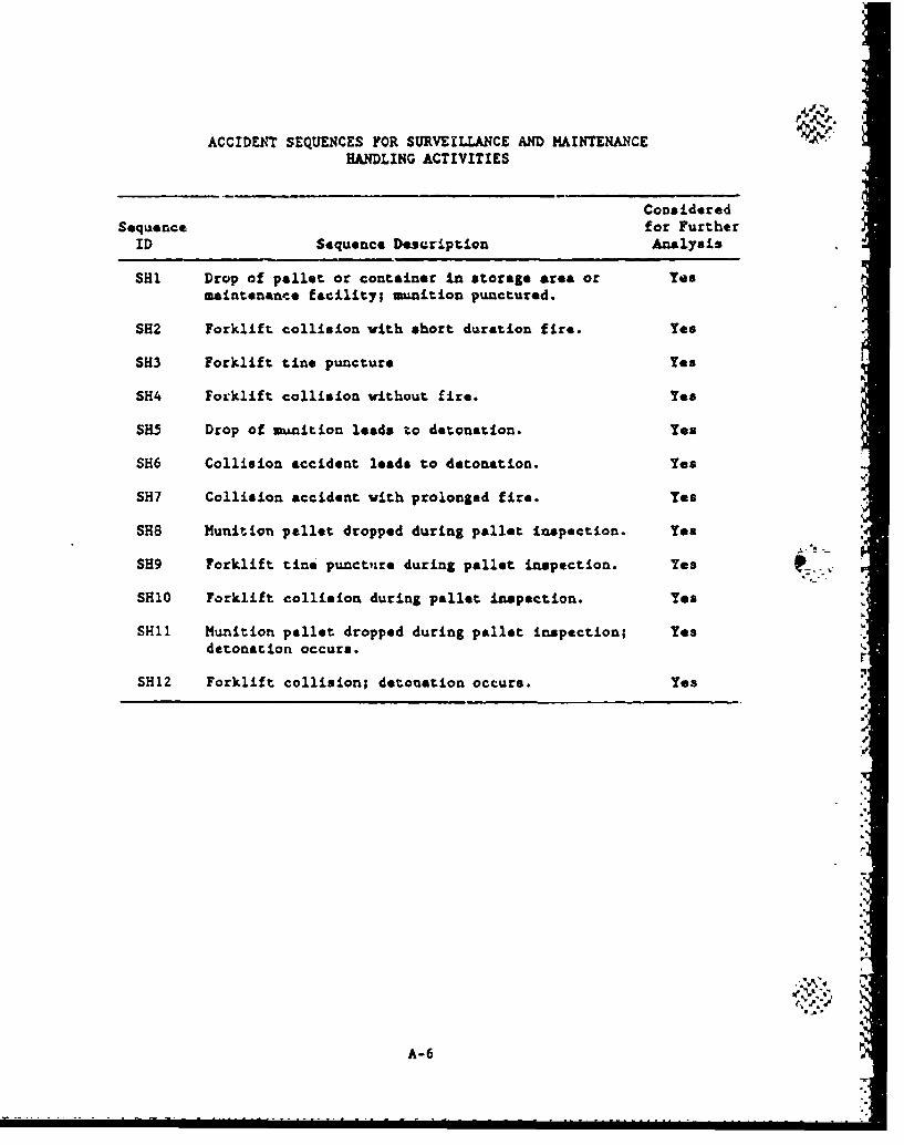
ACCIDENT SEQUENCES FOR SURVEILLANCE AND MAINTENANCE '4HANDLING ACTIVITIES
CoDsideredSequence for Further
ID Sequence Description Analysis
SHK Drop of pallet or container in storage area or Yesmaintenance facility; munition punctured.
SH2 Forklift collision with short duration fire. Yes
SH3 Forklift tine puncture Yes
SH4 Forklift collision without fire. Yes
SH5 Drop of munition leads to detonation. Yes
SH6 Collision accident leads to detonation. Yes
SH7 Collision accident with prolonged fire. Yes
SH8 Munition pellet dropped during pallet inspection. Yes
SH9 Forklift tine puncture during pallet inspection. Yes
SH10 Forklift collision during pallet inspection. Yes
SHI1 Munition pallet dropped during pallet inspection; Yesdetonation occurs.
SH12 Forklift collision; detonation occurs. Yes
A-6
APPENDIX B
(Deleted)
II
I
I..
APPENDIX u "STRUCrTURAL ANALYSIS _.
',e
IO .J
'r.
p.°4
p0.I-,
S..o
S..
r
mpo
C.1. STRUCTURAL ANALYSIS
This appendix summarizes the structural analysis methodology used
to deterisie failure threshold* and probabilities for manitions and
structures. Supporting calculation for the results used in this study
can be found in Ref. C-I.
C.1.1. PUNCTURE
This section addresses two types of umintion punctures (1) punc-
ture due to dropping a munition; and (2) forklift puncture.
C.1.1.2. Puncture Due to Droy
...' The probability PF of a mnuntion puncturing on impact with a probe
depends on the type of uuiitioz., the number of probes to which a dropped
maunition is exposed, and the geometry of the probe. This probability is
computed from the followings
PF a Pg x PLL x PD x A.
where PB - probe density (number of probes peL square foot of surface
area),
PLL - an admissible probability value for probe length to diameter
ratio,
PD - an admissible probability value for probe diameter,
C-1
S.. . . . . . . .. . . . . . . . . .. ...... . .. . .. . .. .. ... .... ..... .. . .... . . .. .. .. ... .. .. .. . . . .. .. .. .. . . . . .. ..- -
As - the area of the nanition in square feet which is subject to
penetration by the probe.
The number of probes per square foot of surface area (FB) is based
on enginering Judgment. It is assumed that the igloo is clean and that
objects that could be potential probes are not likely to be left in the
igloo. Therefore, one probe per igloo (i.e., one probe per 2160 ft 2 )
was assumed for igloo storage. For all other storage areas, a probe
density of one per 1000 ft 2 was assumed. In the general wrking area,
loading docks, etc., it is assumed that the potential for probes will be
-much more likely than in an igloo. Probes such as posts, tools, rocks,
or chunks of steel are possible; therefore, one probe per 100 ft 2 is
assumed for the general working area. In the UPA during an earthquake,
it is assumed that the earthquake could generate additional probes by
causing objects to fall onto the floor; therefore, one probe per 50 ft 2
is assumed for the UPA during an earthquake.
The PLL term in the above expression represents the probability .. 'that the probe has a length-to-diameter ratio (L/D) which is less than
that which wuld cause buckling failure of the probe without penetration
of the dropped munition but greater than that corresponding to a probelength -£hich is insufficient to penetrate the munition. Probe dimen-
sions (diameter and L/D) were treated statistically and the minimum
probe length for penetration was calculated for each munition.
The PD term in the above expression represents the probability
that the diameter of the probt is less than or equal to the maximum that
could penetrate the munition but greater than a miimu diameter corres-
ponding to the compressive strength of the probe. The maxium diameter
of the probes which could penetrate through the m-nition wall is dater-
mined from
(W x H) 0 . 6 6 7
D-u 672 t
C ,2 .%,
C-2 d
where Du a maximum probe diameter (in.),
W - weight of manition/paliet (lb),
H - drop height (ft),
t a munition thickness (in.).
These expressions are taken from Ref. C-2.
The munition area vulnerable to probe penetration (A.) was deter-
mined assuming a maximum probe length of 2 in. This term was calculated
for each muinition/pallet configuration of interest and reflects the num-
ber of munitions involved in each handling operation. Thus, if more
than one munition were being handled, the vulnerable area of each muni-
tion was multiplied by the actual number of nanition. involved in the
handling event.
C.1,1.2. Forklift Tine Puncture
For forklift tine puucture, the intuitions are at rest and the probe
(the forklift tine) is the moving object. This makes calculating the
munition vulnerability simpler since the mass of the moving object (the
forklift) and the shape of the probe (the tine) are the same for all
munitions. The only variable is the munition thickness. Since the
puncture energy is proportional to the thickness of the munition, the
relative puncture resistance of the munitions is simply the retio of thethicknesses.
The probability P of a forklift tine puncture of the manitions was
assumea to be governed by
P - Pl * P2 *N ,
where P1 " the probability that a munition is struck by a forklift tine
per pallet operation,
C-3 '"
~V ~ ~ ~ (' h
v
P2 - the probability that the munition is punctured Liven that the
forklift tine strikes the --nmtion,
N - number of handling operations.
The critical puncture velocity V. (in ftis) was determined from
64Vc 7- (672 Dt) 3 /2
where W - weight of the forklift (ib),
D - equivalent diamter of the forklift tine (in.),
t - munition wall thickness (in.).
C-4
-A• --- I
C. 1.2. W1tfl-GENERCTED MISSILES
The probability of a vind-generated missile rupturing a mmaition is
the product of tu probabilitiea: (1) the probability of having & wind
of sufficient velocity to Senetrte a mi3sile that can rupture a malnition
and (2) the prcbability that the miisi1 hits the munitions in an orien-
taticn that will rupture the ninition.
C.1.2.1. Required Wind Velocity
The wind velocity required to generate a missile that can penetrate
a muanition is computed aa followa Pm
1. The missile velocity required to penetrate the munition is
computed using the equation (Ref. C-2):
64 %C.. Vm - 0.682 (672 Dt) 3 / 2
where Vm - the penetration velocity (mph),
W - the weight of the missile (lb),
D n the equivalent missile diameter (in.),
t - the wall thickness of the uL~nition (in.).
Each munition was evaluated for two critical missileat a
10-ft section of 3-in. pipe and a 13.5-in. diamter utility
pole. In addition to penetration, the utility pole was
evaluated to determine the velocity required to crush the
muanition.
C-5 " ,
Wkl
4.
2. The missils velocity required to penetrate the storage
structure was alro computed using the following equation
(Ref. C-2).
For concrete structures;,
fe T D1 8 0.V-1 000 427 W
whare T = thickness of concrete element to be just
perforated (in.),
W - eight of missile (ib),
D - diameter of missile (in.),
Vs - striking velocity of missile (fps),
fe M compressive strength of concrete (pai).
For steel structures"
64Vs = 0.682 (672 DT) 3 1 2 "-..
3. The Missile velocity required to penetrate both ths n~nition -e
and structure is computed using the following equation which
is based on su-ing the energies required to penetrate the aw•nition and structure separately:
S~.-V a I/ + .
where Vm f velocity required to penetrate the munition,u
Vs M velocity required to penetrate the structure.
4. Th. probability of the requirod wind occurring was based on
functional data for each site. ,.'..
C-6
C.1.2.Z. Probability of Hitting and Rupturing the Munition
Given a sufficient wind, the probability that a missile hit* and
ruptures a munnition wvs computed from:
Pa Pd Po DA
where Pd - probability that the direction ! missile travel is nearly
perpendicular to the target,
Po - probability that the missile is oriented to penetrate (i.e.,
not tumbling or going sideways),
D - number of missiles per unit area,
A = area of target.
Values for Pd, Po, and D are difficult to evaluate and are not available
from the literature. Consequently, the values used for the analysis
were computed based on engineering Judgment. These values were selected
to give a 'best estimate" of the overall probability. The following is
a discussion of these assumptions.
The missile velocity mist be nearly perpondicular to the wall of a
structure or munition in order for the missile to penetrate. The fur-
ther the missile strikes from an angle which is perpendicular, the less
likely that the missile will penetrate. As the angle deviates from the
perpendicular, the effective thicknese of manltion increases propor-
tionally to the reciprocal of the cisine of the angle (where the angle
is measured fror. the perpendicular); thus, a higher misils velocity
(which has a lower probabllity of occurring) is requited for penetrK-
tion. In addition, the missile is more likely to ricochet at higher
angles. Based on engineering judgment, it is estimated that if the
C-7
m2ssile velocity is mre than 30 dog off from perpendicular, the missile
will not penetrate. This yields a value of 0.17 for Pd"
The missile velocity must bo aligned along the missile axis in
order for the missile to pamatrate. In other words, the missile m=st
move like an arrow r.#tb.r zh4& tumbl-ng or going sideways. Of the two
missiles analyzed, it v," fcA thst it is more important that tbo pipe
be aligned proerl-' than te ý- .• "ity pole bucause of the larger impact
area of thit ilij a , ei p¢e U;,As reason, it s "assumed that the
velocity mt. ba• {,rej *'ýthln 5 dog of the axis of the pipe and within
10 dog o! -be ax. - v.6 e utlity pole. These assumptions resulted in
valu* lfo." P0 oi 0.004 tor th* pipe and 0.015 for the utility pole.
Th3 path of ths toruado is generally from 118 to 3/4 of a mile
wide (Rof. C-1". For this analysis, it was assumed that the tornado
is 1i2 mil'e wide and that it carries one utility pole and 10 iron pipes.
It was further assumed that the pipes are evenly distributed to a height _
of 50 ft and the utility pole at a height of 20 ft (Ref. C-4 indicates
the maxi-1m heights for pipes is 100 ft and for utility poles In 50 ft
which indicates that our assumption is conservative). Therefore, the
number of missiles per square foot of wind (D) is 7.6 x 10⁻⁵ for pipes
and 1.9 x 10⁻⁵ for utility poles.
The target area is different for each -cenario and dependa on
the number of munitions involved and the storage configuration (see
Rd.•. C-i).
The product of Pd, Po, and D is approximately 5.0 x 10⁻⁸ for both
the pipes and utility pole.
C-8
C.1.3. EARTHQUAKE AND WIND FAILURF OF UBC DESIGNED STRUCTURES
C.1.3.1. Strength Factor of Safety
The Uniform Building Code (UBC) ensures that structures are
designed with a factor of safety. This factor of safety varies depend-
ing on the type of structure, materials used and components selected.
For earthquake and wind loads, this factor of safety ranges from 1.3
to 1.6 for concrete structures designed to ultimate design strength
principals and from 2.6 to 3.0 for concrete and steel structures
designed to working stress methods. For the risk analyses in this
report, it is assumed that the factor of safety will be 1.3 for concrete
structures (since the CONiS structures are being desigted to ultimate
strength) and 2.6 for the steel structures.
C.1.3.2. Wind Loads
For UBC-designed concrete structures such as the HIB, wind does not
govern the design of the main structural comonents. The NDB is a rigid
concrete moment resisting framed and shear wall structure and will fail
under seismic conditions only. For the steel structures such as the
bulk agent -darehouses, the wind governs the design in most cases. Wind
loads will fail the walls of the structure before the structure will
collapse. Since the stresses in a structure due to winds are propor-
tional to the square of the wind velocity, a wind velocity which is 1.6
(square root of the 2.6 factor of safety on strength) times greater than
the design wind load can be expected to fail the walls of the steel
structure.
C.1.3.3. Earthquake Loads
The Applied Technology Council !ATC), whi.ch it associated with tre
SEAOC, pzesents a set of curves that can be -sud to eatimata the proba-
bility of an earthquake, which exceeds a epucific g-lw.vil, occurring
C-9
r
anywhere in the U.S. (Ref. C-5). These curves are shown in Section 4.2.
Each curve represents a seismic map area which is similar to the seismic
zones used by the UBC. The ATC divided the country into seven seismic
map areas (1-7). The UBC uses five seismic zones (0-4). Reference C-5
contains maps shoving the seismic map areas. These maps color code the
seismic map areas, and, consequently, have not been reproduced for this
report since a black and white reproduction would not be helpful. The
maps show that APG, ANkAD, LBAD, PBA, UHDA, and PUDA are in seismic map
area 2; NAAP is in seismic map area 3; and TEAD is in seismic map
area 5.
Section 4.2 presents the seismic risk curves for seismic map
areas 2, 3, 5, and 7.
The earthquake g-level that will fail a structure depends on four
principal factors: (1) the design 3-level, (2) the strength factor of
safety, (3) the dynamic Amplification in the structure, and (4) the duc-
tility of the structure. The dynamic amplification factor reduces the
factor of safety, and the ductility increases the factor of safety. The
dynamic applification factor has been conservatively estimated at 2.3
based on a referenced analysis (Ref. C-6). Ductility factors are esti-
mated to be in the range of 2.5 to 3.5 for concrete structures with
shear walls and from 3.5 to 5.0 for steel structures. For this anal-
ysis, 2.5 was used for concrete waill and 3.5 was used for steel-walled
Structures. Based on these factors, a UBC structure with concrete walls
was assumed to fail at an earthquake S-level that is approxizately 1.4
times the design g-lyvel, and a UEC structure with steel walls was
assumed to fail At A g-level that is approximately 4.0 time- greater
than the design g-lavel.
For UBC designed structures with concrete walls in Seismic Zone 3
(design g-level of 0.14), the expected failure S-level is 0.4 g. Due
to the uncertainLy of the analysis, there it a probability that the
strucr.ure will survive larger earthquakes or will fail during smaller
C-10
it
- * earthquakes. Conseqtently, the following probabilities of failure have
been assumed:
1. A 0.3-g earthquake has a 0.1 probability of producing failure.
2. A 0.4-S earthquake has a 0.5 probability of producing failure.
3. A 0.5-g earthquake has a 0.9 probability of producing failure.
4. A 0.6-g earthquake has a 1.0 probability of producing failure.
The failure g-levels for Seismic Zone 2 are half of the &-levels for
Seismic Zone 3 since the design g-level for Seismic Zone 2 (0.07 g) is
half the design g-level for Seismic Zone 3 (0.14 g).
For UBC designed structures with steel walle in Seismic Zone 2 (the
warehouses at NAAP and UMDA), the following probabilities of failure
have been asaumed:
1. A 0.2-g earthquake has a 0.1 probability of producing failure.
,. 2. A 0.3-g earthquake has a 0.5 probability of producing failure.
3. A 0.4-g earthquake has a 0.9 probability of producing failure.
4. A 0.5-g earthquake has a 1.0 probability of producing failure.
C-11
------ - -. A
C. 1.4. EARTHQUAKE FAILURE OF NRC-DESIGNED STRUCTURES
The TOX cubicle, tank, and piping system will be designed to
Nuclear Regulatory Commission (NRC) standards for nuclear power plants.
In summary, this will involve the followingsS
1. Seismic experts will determine the "mzxim credible earth-
quake" that can occur at TEAD based on the seismic history of
the area and the proximity of earthquake faults. This 'maxi-
mum credible earthquake" will be selected as the safe shutdown
earthquake (SSE) to be used so the design earthquake for the
TOX at all eight sites.
2. The TOX will be analyzed for the SSE using finite-element
time-history computer programs.
3. The TOX will be constructed to NRC standards.
Since the design g-level has not yet been determined, an SSE g-level had
to be assumed with the intent to ensure that the TOX will withstand rel-
atively high g-forces. For this risk analysis, it was conservatively
assumed that the TOX will be designed for a 1-g SSE.
Since the TOX will be designed for no failures in the event of a
SSE, an earthquake larger than the SSE will be required to produce a
failure. Since the NRC seismic design requirements are quite different k
from the UBC seismic requirements, the methodology used to determine
failure g-levels for the UBC structures does not apply to NRC-designed istructures. Based on GA's experience in seismic design of nuclear power
plants, it was estimated that "n earthquake which is twice the SSE will
have a 0.5 probability of either rupturing the TOX tank/pipin", system 0
or breaching the TOX wall. There is a possibility that the TOX will
ur'vive l.rger earthquakes or that a smaller earthquaks will cause a
I)
'/,
~ failure. Consequently, t1e following probabilities are selected for the
rupture of the TOX storage tark and for the breaching of the TOX walls 2
1. A 1.8-S earthquake hap a 0.1 probability of producing failure. .
S"2. A 2.0-g earthquake has a 0.5 probability of producing failure.
3. A 3.0-g earthquake hats a 0.9 probability of producing failure.
4. A 4.0-g earthquake has an -1.0 probability of producing
failure. "
.'4
C-131
5.5
d"
,I r.• •. 5,
... %
C.1.5•. METEORITES •
The probability of a mteorite penetrating a muadtion can be eati-
mated from:
P - l (fi + f)AS ,
where F - frequency of smtoorite strikes per square foot of area,
fi fraction of the striking meteorites which are Iron meteorite.
and can pestrate, the target,
o- fraction of the striking meteorites which are atone meteor-
ite* and can penetrate the target,
A area of tar&et,
.v • IX
S fraction of the target area which mast be imacted to rupture
a vanition or bulk agent container (spacing factor).
The frequency of meteorite strikes for menteorites 1.0 lb or greeteris 0.4 x 10⁻¹"3/ft2 (Ref. C-7). FoQr s-,a.1 samteoritee (a ton or less),
atone meteorites are approAimLtely 10 times more common than iron mete-
orites (Ref. C-8). However, icon mteoorites are more deanie and tend to
have higher impact velocities, and consequently, represent a significant
portion of the total meteorites that catt rupture wunit.lons. The mise
distribution of both iron said stone meteorites strkinag the earth our-
face wea estimated from the data presented in lefs. C-7 and C-B.
The site of the meteorlte requi•ed to penetrate a snit Lori, or
munition and structure wet computed using the equatiorn presented In
Ref. C--2. The impact velocity was computed based on the data presented
• -.
* "ra,,
• •,K• ,, , , / • .- , r•• • ,• - •• / • • " V"•,, • ./ . • • •"-• "-- 4, , ,-, • •-, .. 0..', .,1- . ..
I-
•
p..
in Ref. C-8, which gives impact velocities for a series of larSe meteor-
it*&. These data wre plotted and extrapolated to estimate the veloci-
ties for the semaller mateorites. For the smallest stone mteorites, the
extrapolation yields impact velocities which were less than their ter- i
winal velocities. In these cases the terminal velocities are used.
I,"
-CI1
Mr
I-"
-p. -•
C.1.6. AIRCRAFT CRASH
The probabilities used in the analysis of crashes involving air-
craft takeoffs and landings were obtained by mdifying Table C-I, which
was taken from Ref. C-9. The following modifications were made to this
table:
1. U.S. air carrier (commercial) crash probabilities between 5
and 8 miles from the end of the runway were increased from 0.0
to 0.14 x 10⁻⁸ which is equal to the probability for crashes
between 8 and 9 miles from the end of the runway.
2. The probabilities for USN/USMC were averaged with the proba-
bilities for USAF to obtain probabilities for military air-
craft in general.
3. The probabilities for crashes of military aircraft at dis-
tances which are 5 to 10 miles from the runway were assumed to
be the same as for U.S. com•ercial air carriers.
4. The general aviation probabilities for crashes which are 5 to
10 miles from the end of the runway are assumed to be five
times greater than U.S. air carrier probabilities.
5. Helicopter crash probabilities were assumed to be twice the
probabilities for general aviation.
Tables C-2 through C-17 summarize the input data that were used to
calculate the annual probabilities of both small and large aircraft
crashes at each of the eight sites. The effective areas of the crash
sites are summarized in Table C-18.
C- 16
I "'M A. %P - .. A
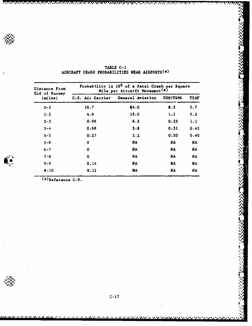
TABL-E C- 1
AIRCRAFT CRASH PROBABILITIES NMA AIRPORTSWa i
Distnce rom Probabi.lity (x 108 of a fatal Crash oer SquareD~tsr~ane F~om Mle par kircarft Kove,--nt(a) --
End of Ruuway.-.
0-1 16.7 84.0 8.3 5.7 t
1- 2 4.0 15.0 1. 1 2.3 3=2-3 0.96 6.2 0.33 1.1i•,
3- 0.68 3.8 0.31 0.42 •
3-'.
4-5 0.27 1.2 0.20 0.405-6 0 NA NA NA -
670NA NA NA-'i.
-.- ,7-8 0 NA NA NA•
-oI,;
9.. -9 0.14 NA NA NA.
MU.
9-10 0. 12 NA NA NA(WReferanco C-9.
lop
K,,
C-17.
AIRRAF CgAS PRO6A'IIE NEA AIRPORTS(')kDistnceFrom Proabiity x ~of ~'aal raa perSq~iar
End f Rui~ey Mie pr Aicarf Moemen (a
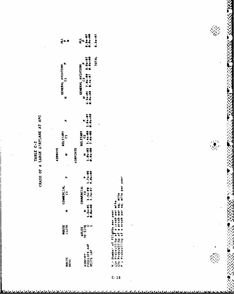
.j 460 j L 0-C foe 1
0: ja~ '
IL a. 1.6 0
P.3S15
4A 44bi b4 I- as.
7-S -
zz
j vi
a. f!f!ý .-..
I-L
.~A.D
j4 A) A. -L4
U ZCC
W. I.
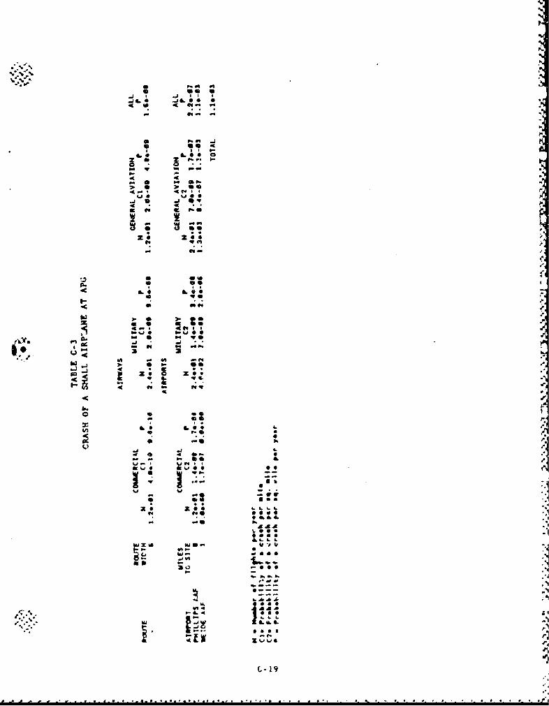
-aK
ID J a V
4c. Iag 0 1 aI
* 4A C4
W- j
46 46
~~*L 5. L2 fA 6u a
4-'4 4(4I
-l *'Y
C- 1-
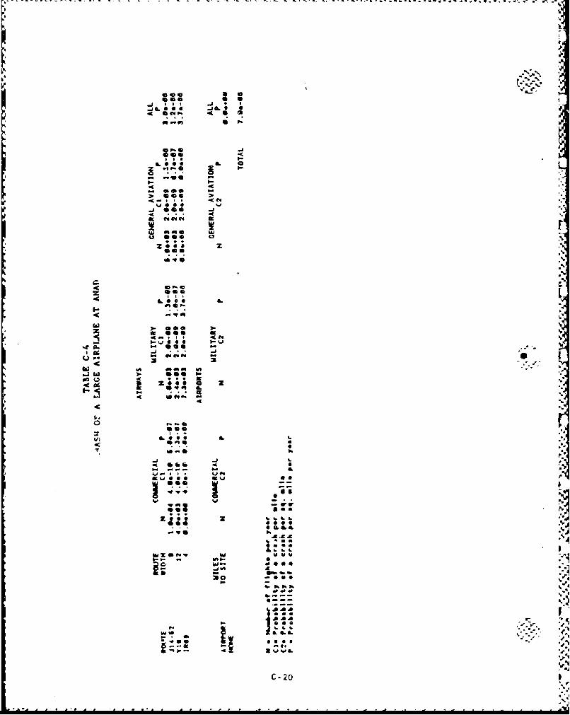
-~~~~~ a'.u.f t. j 4 '& A. w~t ~ K d. ~ r t~
011
O-C
z see
)- 0eO ).jg W
02 -J
41 IS
20 4~
AAAa : .5
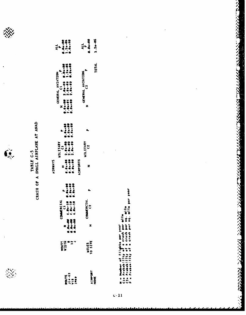
J C 04 .
.49
SW..See 44S* I-
mom .0400S pp~sS cm
_j one .
64 .. 46
as*
%J- %UC4
41 SOS 00
4i * i 4
22 1
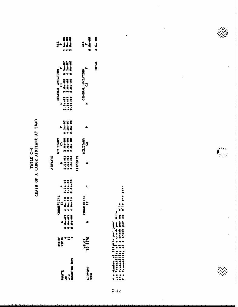
go*V
.. P%
.4n .0eO
s ee 0
I.,.6.0.. J~t t.S .
zo6. AA
"44.
-A-
06 ft % 0
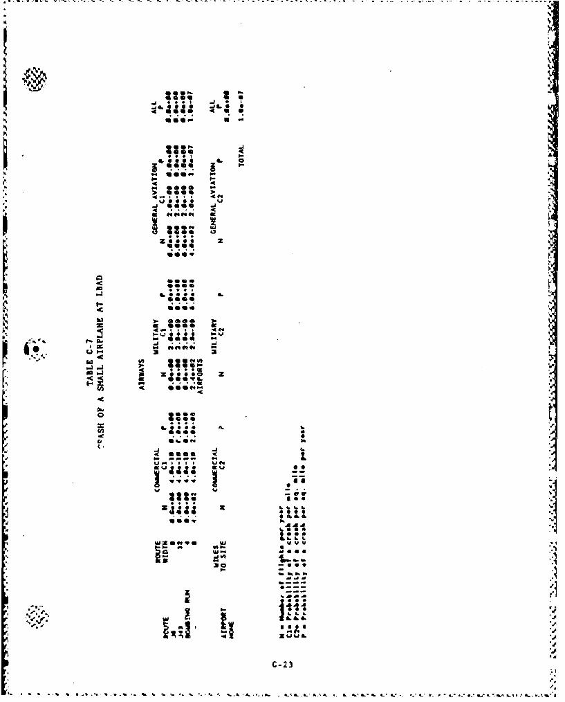
.,,~
*e~g ~L 0
i "L•0000
I~I-
-4 4
.4*0000
4m . , C4 4
4 6
000=0
a*s~
.5.
99 ON .th 0 -1. til "
mas
z.4 04I &1
44m z..C-23
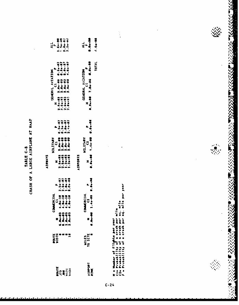
4 IA v ie ev0
'a6 .0 4 4 I 0
-1 ee* J
#A Ct414 gt
M.. 4i
46 00 16
0*000
01 4% v
6..P.. u
@06S S4i 24
C-2 400
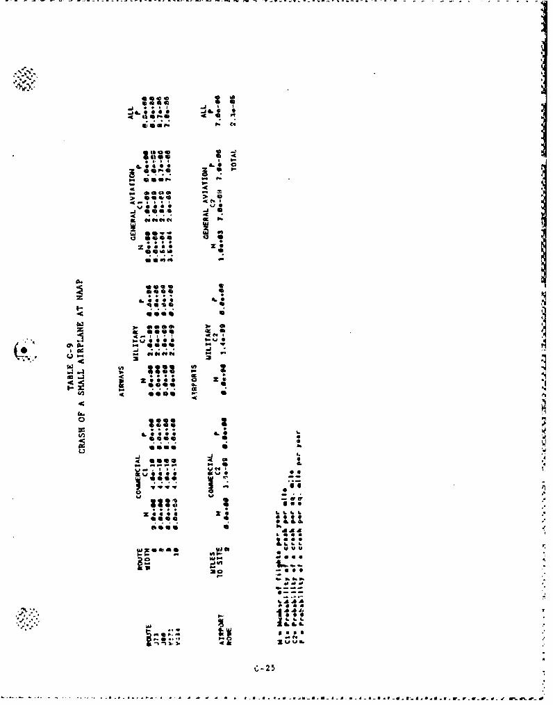
S~ ~~~~~~~ 46 S'~. ar r~~r .. - vv
t*o a 4i I -j
p. a I
a... 0..
4J 006
K q *I
z, ,00 z
6644 1
In.qD.
,. ..* ) 0
£c wO
z-O @ .~*45 55. 64.6 I
(*) ~4 .4 4'4t44AAA
L6L
In 4 eSS.
In 0.0 .. 77
ff ff d. 0. f W% rdiL
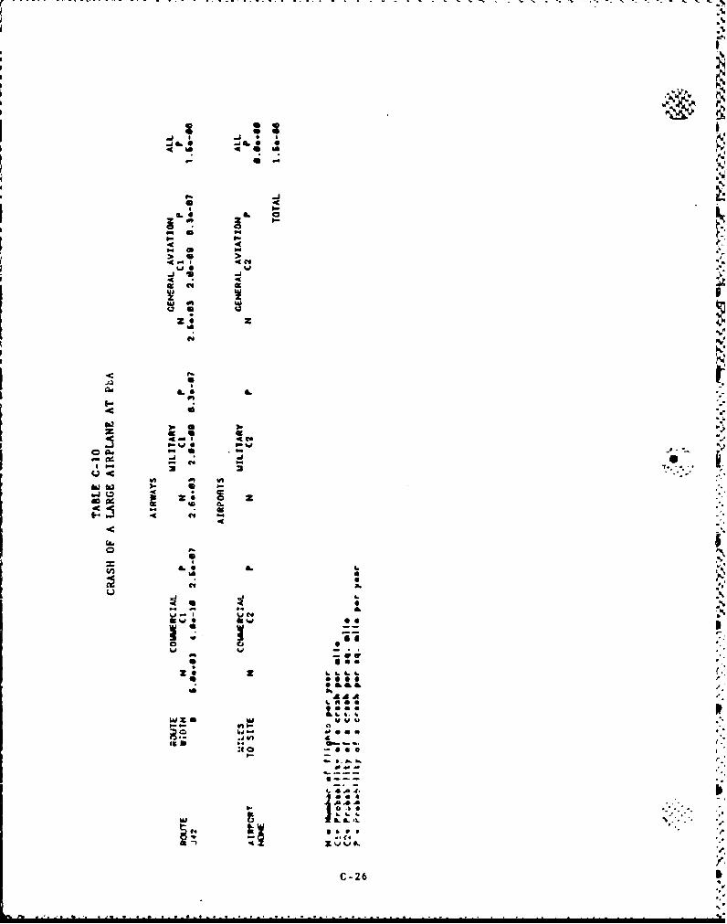
IsI
I* 4
44
40; UIL L -
01p
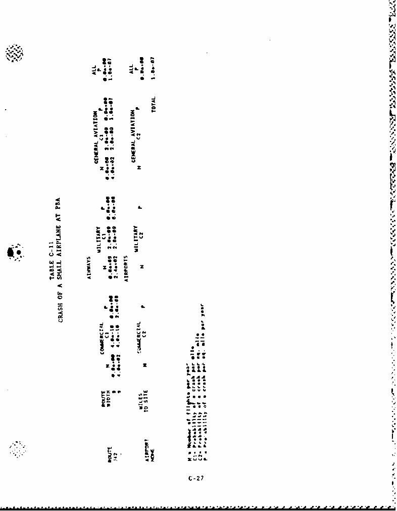
° I
4' a
I-'
'40
Lj BO* .LO
soo
S **
Q*1..
0 4L
CIO
-p
4i
b.. b.
4 *.
u :.U
-- 27
. A0 P
-,, . * 0 ) , ,*•,* 0I , • • • •; • -I , "*h *L *"# •!l " 1 • " t"I I* 'I "I"t ' ,
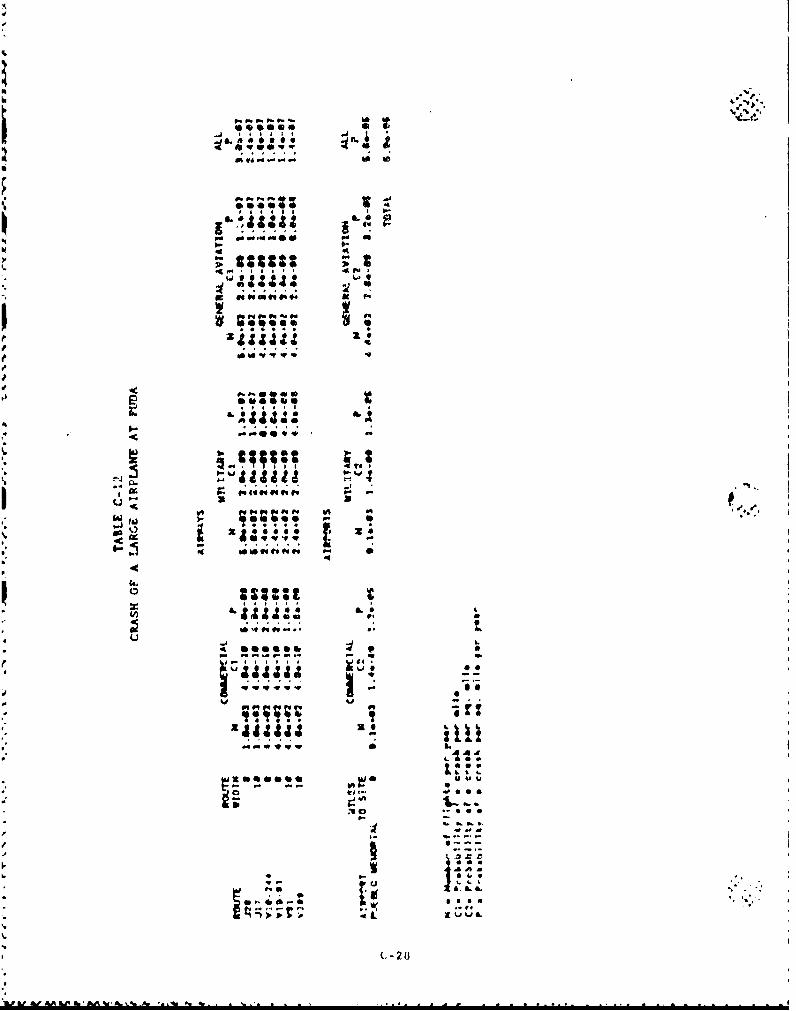
0;#4
A.1.
40 4" u
9 '
A.. IL.
%J Lia
2 t
W t A% 9', W^
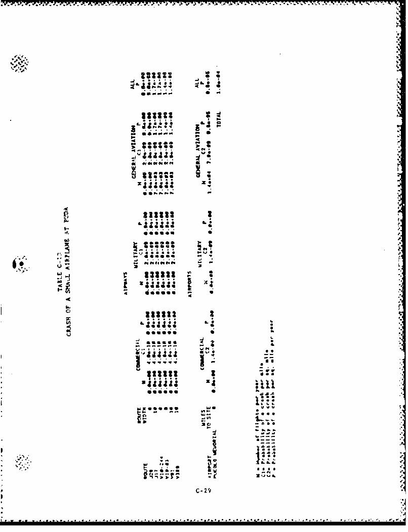
6~V I~ YT) - . -I' 11 . N.6 .. b. - - - --
46 C3
00 :l I .
a,*4 00lb,
46 6
-0 as..
ft# 0 4 4f
; '''Ss
4'0
46&Aa
I-. C-29
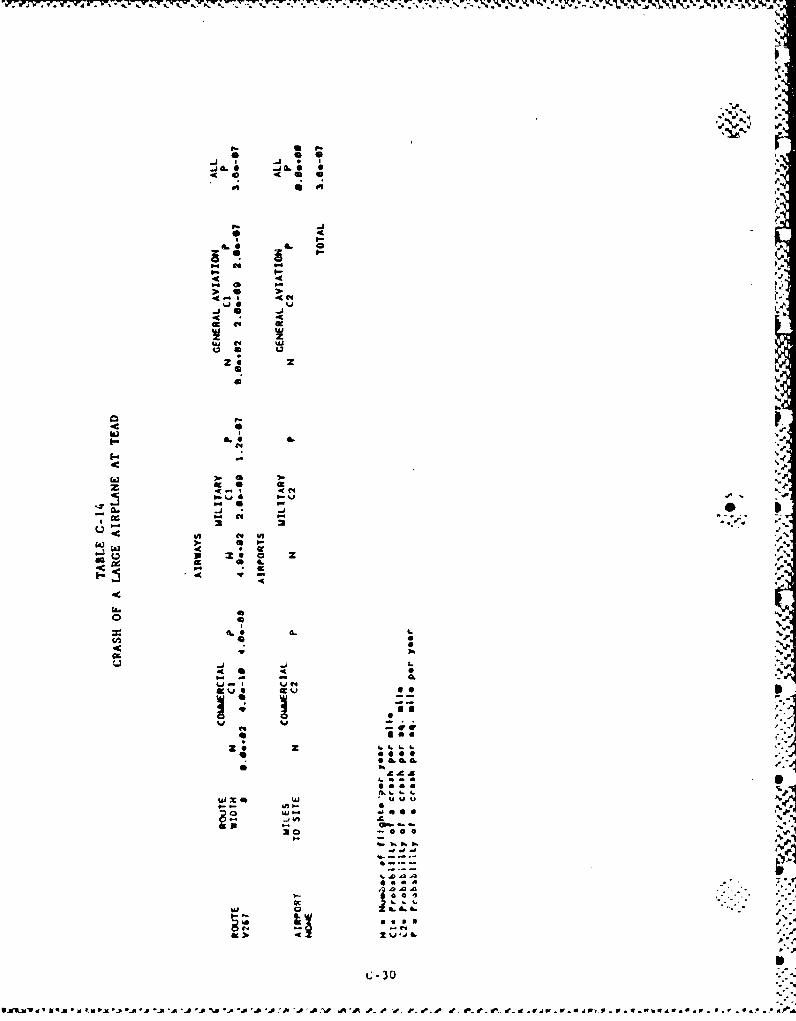
~'-~' .~'r~ r I V0 -JC 0 - r 2-K 0 A z
06 0 46
ll,.
46 0 46
Grr* 4
£4 PS
S.P. 'A5
,. AAA
4-' 4IL
4 * 4
~ £430
vmRM .( i .m i P . .0-0 .a . .0'a '0 A'0 .. W qO e -r ,e F P . r.If t fj .a "p v P W-
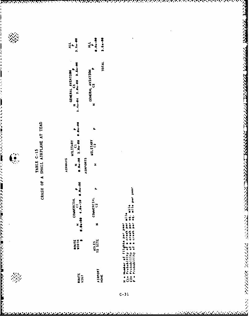
-j a.
p 6 6
a.go.
4 . uj
-1 I'
4~4 0
Va
Jc
C-3
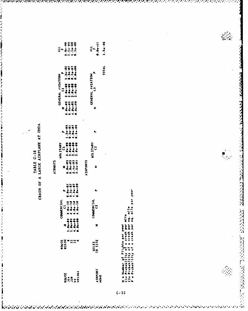
t~ti j C 9
41
QOO agei
lk sam
egos
;~0 6
4:~ticc.2.~ocv
No t
9-4
4L o 00600
0.1 fn
tot.0 0.
'46 m%10,3%
1- 0 a
.1 0 --,.
4r. .-1 -
9... ~L L '
-i-I"I~bAP
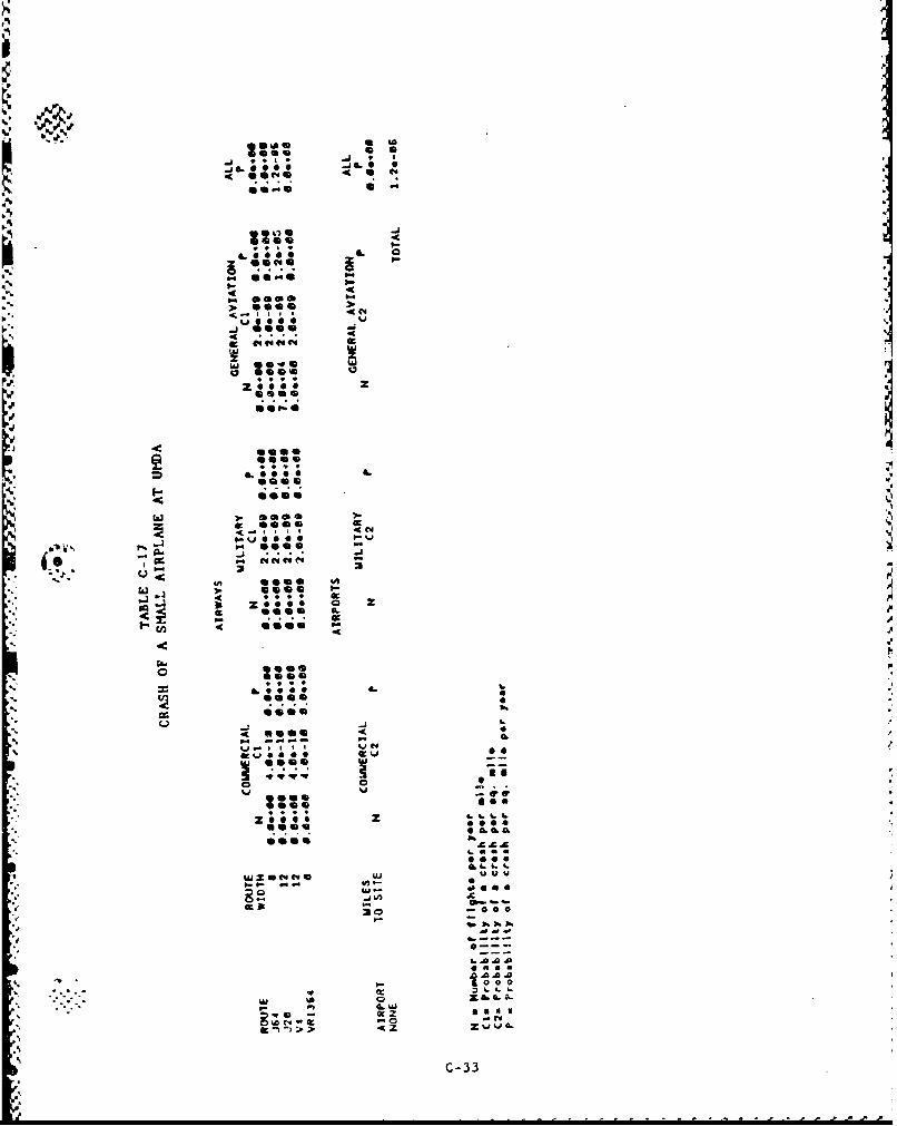
US iS of to
OL IL
10-1
.*• . 9-
-Ce
e4 C%
IL 0OW
M eem
i' II I' 4QC4
.J .5.5
o -
se e CL
,',•zoo..o,'- • ... "
. . . . 6
.-. :~ ..-. •.
so6 4L 0.-., 0.... *•
"- OO ie i e . ,
*se -
4. ev v
,-.~~~0 .:.--. 3, 34'•
4 5 A- a-
.'c
.C-33
k. . . . . . . . . . . . .pP
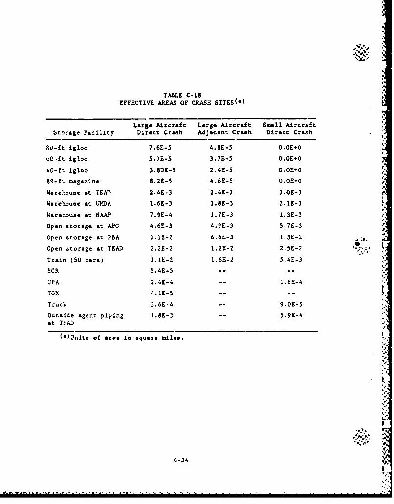
TABLE C-18EFFECTIVE AREAS OF CRASH SITES(&)
Large Aircraft Large Aircraft Small AircraftStorage Facility Direct Crash Adjacent Crash Direct Crash
80-ft igloo 7.6E-5 4.8E-5 O.OE+O
60cft igloo 5.7E-5 3.7E-5 O.OE+O
40-ft igloo 3.8DE-5 2.4E-5 O.0E+O
89-fý. magaz.ine 8.2E-5 4.6E-5 0.OE'0
Warehouse at TEA"ý 2.4E-3 2.4E-3 3.OE-3
Warehouse at LISA 1.6E-3 1.8E-3 2.1E-3
Warehouse at NAAP 7.9E-4 1.7E-3 1.3E-3
Open storage at APG 4.6E-3 4.VE-3 5.7E-3
Open storage at PBA 1.1E-2 6.6E-3 I.3E-2
Open storage at TEAD 2.2E-2 1.2E-2 2.5E-2
Train (50 cars) 1.1E-2 1.6E-2 5.4E-3
ECR 5.4E-5 ..
UPA 2.4E-4 1.6E-4
TOX 4.1E-5 ....
Truck 3.6E-4 -o 9.0E-5
Outside agent piping 1.8E-3 -- 5.9E-4at TEAD
(a)Units of area is square miles.
W3C-34-
C.1.7. REFERENCES
C-i. "Supporting Calculations for the Risk Analysis of the Disposal
of Chemical Munitions at National or Regional Sites,* GA Report
EPS-GA/DP-0092, August 1987.
C-2. 'Design of Structures for Missile Impact," Bechtel Power Corpor-
ation, BC.TO-9A, September 1974.
C-3. "Standard for Estimating Tornado and Extreme Wind Characteristics
at Nuclear Power Sites," ANSI/ANS-2.3-1983, 1983.
C-4. Coata, D, W., *.Natfonal Phenomena Hazards Modeling Project: rExtreme Wind/Tornado Hazard Models for Department of Energy
Sites," UCRL-53526, Lawrence Livermore National Laboratory,
February 1984.
C-5. "Tentative Provisions for the Development of the Seismic Regula-
tions for Buildings," Applied Technology Council, ATC 3-06,
NES SP-510, NSF 78-8, June 1978.
C-6. "Structural Analysis and Design of Nuclear Plant Facilities,"
American Society of Civil Engineers, Manuals and Reports on
Engineering Practice No. 58, 1980.
C-7. Solomon, K. A., K. C. Erdmann, and D. Okrent, "Estimate of the
Hazards to a Nuclear Reactor from the Random Impact of Meteor-
ites," Nuclear Technology, Vol. 25, January 1975.
C-8. Blake, V. E., "A Prediction of the Hazards from the Random Impact
of Meteorites an the Earth's Surface," Sandia Laboratories
SC-RR-86-838, December 1968.
C-9. "USNRC Standard Review Plan," Section 3.5.1.6, "Aircraft Hazards,"
U.S. Nuclu&A: Regulatory Commission, NUREG-0800, July 1981.
IN
C-35
• • ,*, • '.A .- ,,- ,•- , , . ,.y * U U- -,.-.- .-p p '. .P. " . *'o .V'.- , 'k N
APPENDIX DSITE INFORMATION
* i
6--
-*
..
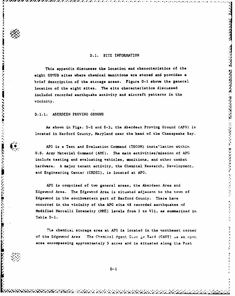
r IF r %- r
D.l. SITE INFORMATION
This appendix discusses the location and char.cteristics of the
eight COnUS sites where chemical n-nitions are stored and provides &
brief description of the storage areas. Figure D-1 shows the general
location of the eight sites. The site characteristics discussed
included recorded earthquake activity and aircraft patterns in the.• vicinity.
D.-.1. ABERDEEN PROVING GROUND
As shown in Figs. D-2 and D-3, the Aberdeen Proving Ground (APG) is
"* located in Harford County, Maryland near the head of the Chesapeake Bay.
* APG is a Test and Evaluation Comand (TECOM) instA'.lation within
U.S. Army Materiel Command (AMC). The main activities/mission of APG
include testing and evaluating vehicles, munitions, and other combat .,hardware. A major tenant activity, the Chemical Research, Development, 4
and Engineering Center (CRDEC), is located at APG.
I...
APG is comprised of tw general areas, the Aberdeen Area and
Edgewood Area. The Edgewood Area is situated adjacent to the town of
Edgewood in the southwestern part of Harford County. There have
occurred in the vicinity of the APG site 48 recorded earthquakes of
Modified Mercalli Intensity (MMI) levels from I to VII, as suarized in
Table D-1.
""LTe chemicai storage area at APG is located in the northeast cornerV of the Edgewood Ares The Chemical Agent S%.r Oa Yard (CASY) As an operi
area encompassing approximately 5 acres and is situated along the Push
D-1
;e
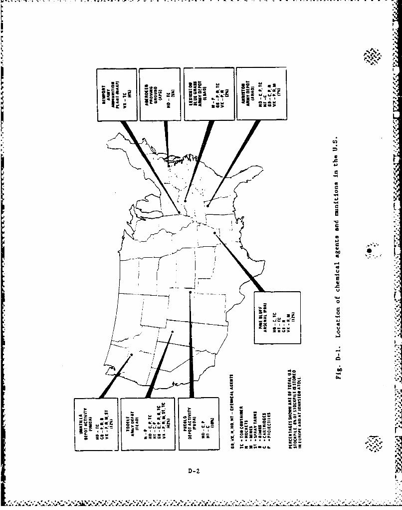
a.
II
-'< -
... 4_
, I,
0 , VI
-'8 ...--- I L--! = w
- W-D-2 U*
•*",/" , ''' ''•'"•"% '•%•% % %•% % %'•*•r •" - , - r " 5 4 , ., ,H
w . -"
~~~ i\\" c,. t ?* Uo
al,
~.WOa
| ,4"
01
D-3.
I:" i -:.
S"".'5
,,,00,
O-3 -C
A•,'•• ,,, , , -."-•'•:'•'•4.,•,• •,,'. •..:.. .. .0
/, 4,4,A•L .. .. •"- - o.. . . . .
•u +%" 44
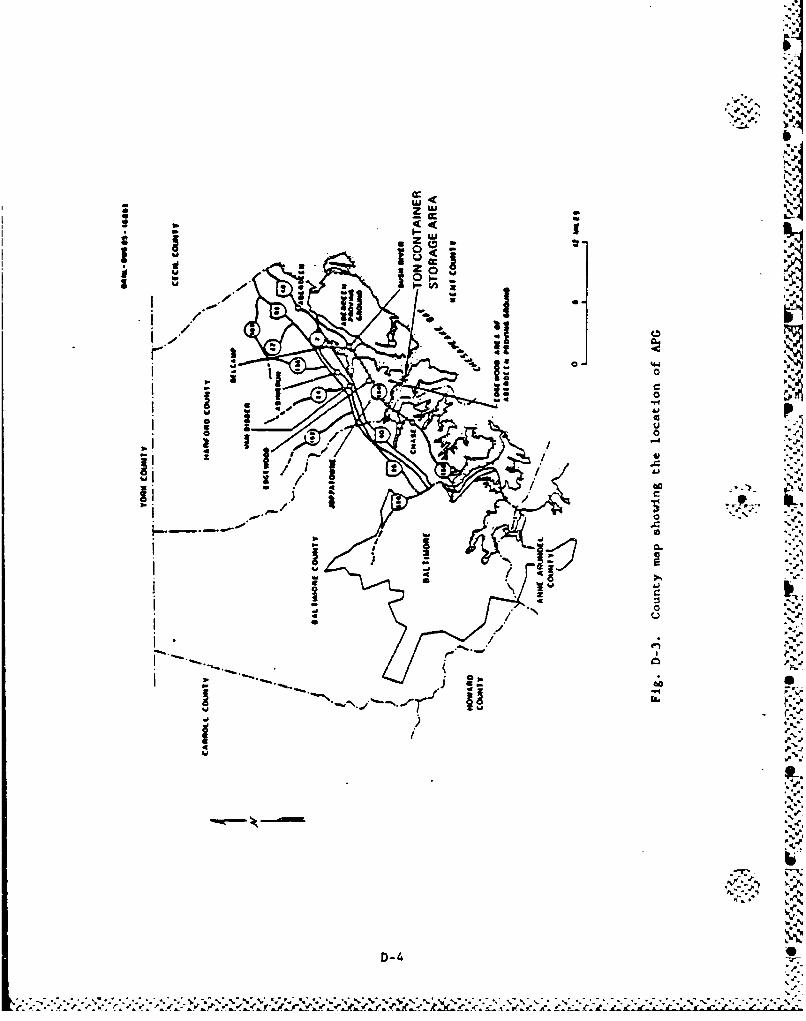
b
* ~ZW
Z 00g
IlIkI-.
21"
60c
,. /- / *.
i It / l " - ' ""-....
-Now-
_ ,-", ,i " - ., - ." " i -. "
.v.T
•
D-4
&<..- .'. ".° . . ... -_.• . ... it" .'t:• _cl'x "_i¢, ,r _,.Ž Žr .," 2,t" ... Ž•.• ;> L ..
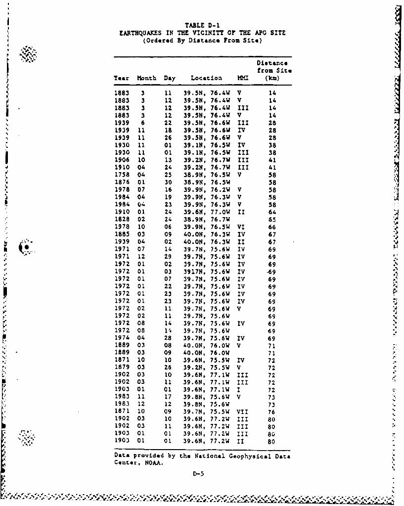
TABLE D-1EARTHQUAKES IN THE VICINITY OF THE APG SITE
(Ordered By Distance From Site)
Distancefrom Site
Tear Month Day Location HK (km)
1883 3 11 39.5N, 76.4W V 141883 3 12 39.5N, 76.4W V 141883 3 12 39.5N, 76.4W 111 141883 3 12 39.5N, 76.4W V 141939 6 22 39.5N, 76.6W I11 281939 11 IS 39.5N, 76.6W IV 281939 11 26 39.5N, 76.6W V 281930 11 01 39.1N, 76.5W IV 381930 11 01 39.1N, 76.5W IV 38
1906 10 13 39.2., 76.7W I1I 411910 04 24 39.2N, 76.7W 1II 411758 04 25 38.9N, 76.5W V 581876 01 30 38.9N, 76.5W 581978 07 16 39.9N, 76.2W V 581984 04 19 39.9N, 76.3W V 581984 04 23 39.9N, 76.3W V 581910 01 24 39.6N, 77.0W II 641828 02 24 38.9N, 76.7W 651978 10 06 39.9N, 76.5W VI 661885 03 09 40.ON, 76.3W IV 671939 04 02 40.0, 76.3W 11 671971 07 14 39.7N, 75.6W IV 691971 12 29 39.7N, 75.6W IV 691972 01 02 39.7N, 75.6W IV 691972 01 03 3917N, 75.6W TV 7911972 01 07 39.76, 75.6W IV 691972 01 22 39.7N, 75.6W IV 691972 01 23 39.7N, 75.6W IV 691972 01 23 39.7N, 75.6W IV 691972 02 11 39.7N, 75.6W V 691972 02 11 39.7N, 75.6W 691972 08 14 39.7N, 75.6W IV 691972 08 10 39.7N, 7576W 691974 04 28 39.76, 75.6W IV 691889 03 08 40.0N, 76.0W V 71 =1889 03 09 40.0N, 76.0W 71 •,1871 10 10 39.6N, 75.5W IV 72 .1879 03 26 39.2N, 75.5W V 721902 03 10 39.6N, 77.1W 111 72"
1902 03 11 39.6N, 77.1W III 721903 01 01 39.6N, 77.1W I 721983 11 17 39.8N, 75.6W V 73 '1983 12 12 39.8N, 75.6W 73 "1871 10 09 39.7N, 75.5W VII 761902 03 10 39-6N, 77.2W 111 801902 03 11 39.6N, 77.2W 111 80
•' _-'" "1903 01 01 39.6H, 77.ZW 111 80.. ... 1903 01 01 39.6N, 77.ZW 11 80 "
Data provided by the National Geophysical DataCenter, NOAA.
D-5
% ý..
River. The storage yard consists of a central aisleway of finished con-
crete and the ton containers are secured over a gravel surface. There
are tw buildings in the CASY that are used to store equipment. Only
mustard-filled ton containers are stored at APO and they are stored
outdoors in accordance with AMC regulations.
The airspace above the Edgewood area of APG is continuously
restricted (Restriction No. R-4001A). Permission to fly at altitudes
above 10,000 ft from midnight to 7:00 AM may be requested 24 hr in
advance. The Weide Army Air Field (AAF) is located within a mile of the
storage area. It has a 4600-ft runwray which is used by a general avia-
tion flying club and an Air National Guard helicopter unit located at
Weide AAF. The Army estimates that there are approximately 2600 general
aviation operations (takeoffs/landings), 7200 helicopter operations, and
800 small fixed-wing military operations per year at Weida. There are
no large aircraft operations.
bPhillips AAF is located approximately 8 miles to the northeast. It
has three runways. The longest is 8000 ft. The Army indicates that the
edges of the approach and holding patterns for Phillips are more than
2 miles north of the storage area. Therefore, they are not considered a
threat to the storage area per the guideline of Ref. D-3.
There are three other airports located in the area. Baltimore Air-
park is approximately 8 miles to the west and has one 2200-ft runway.
Martin State Airport is located 8 miles to the southeast. It has three
runways. The longest is 7000 ft. The largest airport in the area is
Baltimore Washington International Airport which is 26 miles southwest
of Aberdeen. Its longest runway is 9500 ft. There are two low altitude
federal airways (V378 and V499) that pass approximately 8 miles from the
storage area. The closest high altitude jet routes (J42-8 and J40) are
approximately 14 miles from the storage area. These airports and air-
ways are not axpected to present a significant threat to the storage
D-6
",•:•" area becau.se of the distances involved aid because the storage area isprotected by the restricted airspace. !
A.-
p.p.-!
A.
A.'A
AC
• • J,"
A.
• D7
A.A.
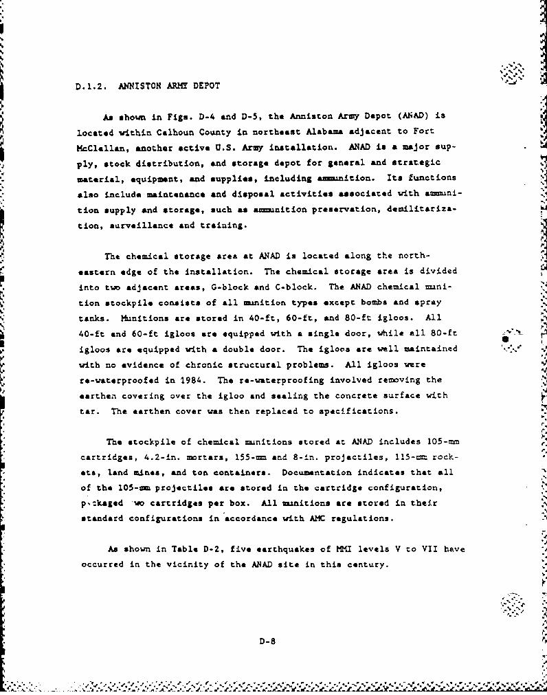
D.1.2. ANNISTON ARMY DEPOT
As shown in Figs. D-4 and D-5, the Anniston Army Depot (ANAD) is
located within Calhoun County in northeast Alabama adjacent to Fort
McClellan, another active U.S. Army installation. ANAD is a major sup-
ply, stock distribution, and storage depot for general and strategic
material, equipment, and supplies, including an4-tion. Its functions
also include maintenance and disposal activities associated with a-ini-
tion supply and storage, such as amunition preservation, demilitariza-
tion, surveillance and training.
The chemical storage area at ANAD is located along the north-
eastern edge of the installation. The chemical storage area is dividedinto two adjacent areas, G-block and C-block. The ANAD chemical muni-
tion stockpile consists of all munition types except bombs and spray
tanks. Munitions are stored in 40-ft, 60-ft, and 80-ft igloos. All
40-ft and 60-ft igloos are equipped with a single door, while all 80-ft
igloos are equipped with a double door. The igloos are well maintained
with no evidence of chronic structural problems. All igloos were
re-waterproofed in 1984. The re-waterproofing involved removing the
earthen covering over the igloo and sealing the concrete surface with
tar. The earthen cover was then replaced to specifications.
The stockpile of chemical munitions stored at ANAD includes 105-rm
cartridges, 4.2-in. mortars, 155-= and 8-in. projectiles, 115-= rock-
ets, land mines, and ton containers. Documentation indicates that all
of the 105--m projectiles are stored in the cartridge configuration,
p,:kaged *w cartridges per box. All minitions are stored in their
standard configurations in accordance with AMC regulations.
As shown in Table D-2, five earthquakes of KI levels V to VII have
occurred in the vicinity of the ANAD site in this century.
D-8
%.
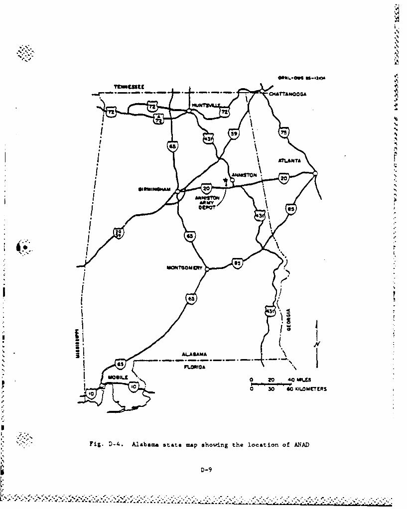
72,
A.
. Is
i "II
ms 0120 40 RPLEI! pI
.a.- .. --
oo 3o-•mrvt
''"Fig. D-4. Alabama state map showing the location of ANAD
D-9
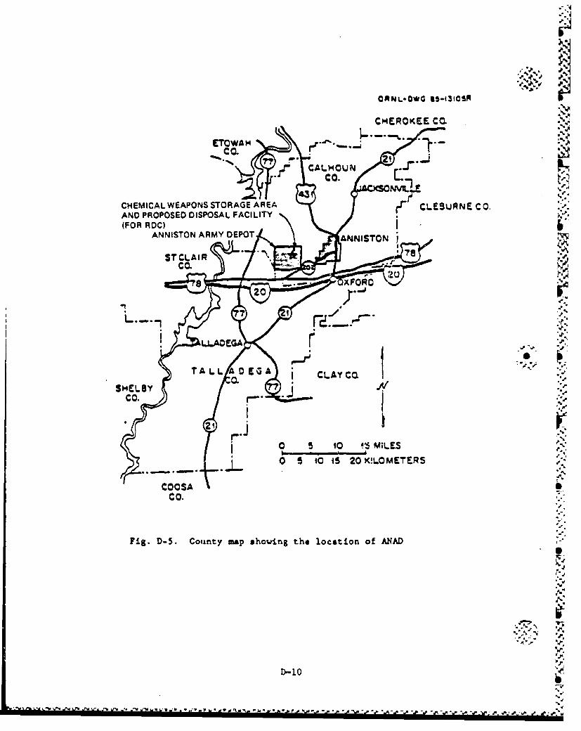
OMNL-OWG IS-1310SR
CHMERO KEE C CO
CHEICA WAPOSETOWAGHAE
CO..
43,
CHEMICAL~~~ WEPNSSORG AE
CO.
"S..
I IP
D-10
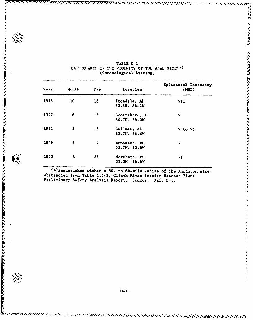
TABLE D-2EARTHQUAKES IN THE VICINITY OF THE ANAD SITE(&)
(Chronological Listing)
Epicentral IntensityYear Month Day Location (I)
1916 10 18 Irondale, AL VII33.5N, 86.2W
1927 6 16 Scottsboro, AL V34.7N, 86.OW
1931 5 5 Cullman, AL V to VI
33.7N, 86.6W
1939 5 4 Anniston, AL V33.7N, 85.8W
i "1975 8 28 Northern, AL VI•-':, :33.3N, 86.6W
I (a)Earthquakes within a 50- to 60-mile radius of the Anniston site,
abstracted from Table 2.5-2, Clinch River Broeder Reactor PlantPreliminary Safety Analysis Report. Source: Ref. D-1.
D-11
V'I tV~V~ . . ~ A . 'N / ,: '.j I W\ ~~j afu4~f~.'.~/ %
,V.-
The airspace above the chemical munition storage area at the ANAD
is unrestrictsd. The airspace just north and northeast of the chemical
storage area is restricted continuously to 24,000 ft (Restriction number
R-2102). The area just west of the chemical munition storage area is
restricted up to a 5000-ft level from 7:00 AM to 6100 PM Monday through
Friday (Restriction number R-2101).
The closest major airfields are Anniston and Talladega, both of
w.hich are approximately 8 miles from the chemical munition storage area.
Anniston has a 7000-ft runvay and can accept aircraft as large as a
Lockheed C-141. Air traffic flying in and out of Anniston must stay to
the south of the depot (Ref. D-l). Talladega has a 6000-ft runway. It
has handled Lockheed C-130s but cannot accept C-141s. Air traffic com-
ing out of Talladega must stay west of the depot (Ref. D-1). Conse-
quently, the edge of the flight path in and out of Anniston and out of
Talladega is at least 2 miles from the storage area.
To the east and north of the city of Anniston, there are two small
airports and a heliport, the closest of which is 8 miles from the stor-
age area. Air traffic from these airports is not a significant threat
to the storage area since there is 3 miles of restricted airspace
between these airports and the storage area.
There is one low altitude federal airway (V18) which passes 6 miles
south of the storage area and one high altitude jet route (J14-52) which I.passes directly above the storage area. The high altitude Jet routeis the preferred jet route for air traffic between Atlanta and Denver
(Refý D-2). Military training route IR69 passes over the storage area
and then returns three miles south of the storage area.
%D-1
D-1Z•
D.1.3. LEXINGTON-BLUE GRASS ARMY DEPOT
As shown in Figs. D-6 and D-7, the Lexington-Blue Grass Army Depot
(LEAD) is located in Madison County, south of Richmond, Kentucky. The j.%
primary mission of the depot is to operate a general supply and a uni- r
tion depot activity providing for the receipt, storage, issue, mainte-
-once, demilitarization, and disposal of assigned commodities. I
The chemical mnnition storage area at LBAD is located in the north
central half of the Blue Grass facility. The chemical munition stock-
pile at LBAD consists of 8-in. projectiles, 155-rn projectiles, and
M55 rockets. These munitiona are stored in 89-ft oval-arch igloos.
Seventy-five percent of the igloos iere waterproofed in 1982. The pro-
cedure involved remving the earth covering the igloo to apply a layer
of tar, and than replacing the earthen cover.
Table D-3 summarizes earthquake activity in the vicinity of the
LBAD site.
LBAD airspace is not restricted. There are three small airfields
in the vicinity of the depot: Madison County Airport, Berea Richmond
Airfield, and Gall& Airfield. Madison County A.rport is approximately
9 miles from the storage area. At the Madison County Airport, there is -•
a civilian flight school which operates light aircraft, ranging from
single engine light planes up to twin engine aircraft. The flight%
school uses two training areas near the depot, one to the north and the .
other to the east. The Madison County airport has a 4000-ft xunway.
The Berea Richmond Airfield is approximately 6 miles from the storage
area and can support only light aircraft on its 2400-ft grass strip run-way. Gall& is a small, private airfield 12 miles east of the storage
area. The air traffic from these airports over the storage area is not
expected to be a signnficant hazard.
D-13
.4.•
S.. . . '• " • • ' a••°' •• • • - • • r' = m = - " ' '
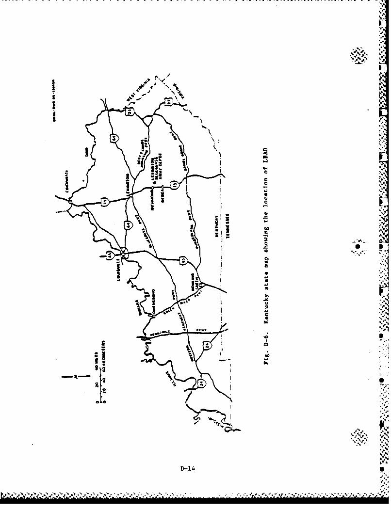
V
j.
�r. '�
41'
II'.
It
ISa
4'.
'.4
'-44''.
'I
"'4'
0* I
* -s.- '.
N*4'
'I
.'.. '1
S
he
S
'./V�. �
.1'
v.4'
D-14 S
.4..
N� *� .S.%\ . . - . 4'*� .5.,. .. . .,... . � ...
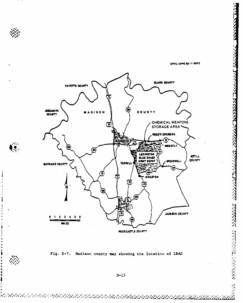
COUNTYY
CHEMICAL WEAPONS
AMVOS ~WEWL COUNTY
Fig.ROAC.$TLIOOUNY
D-7.Madion cunymphoigheocioofBA
~U~n
J40MO CO'N
D-15
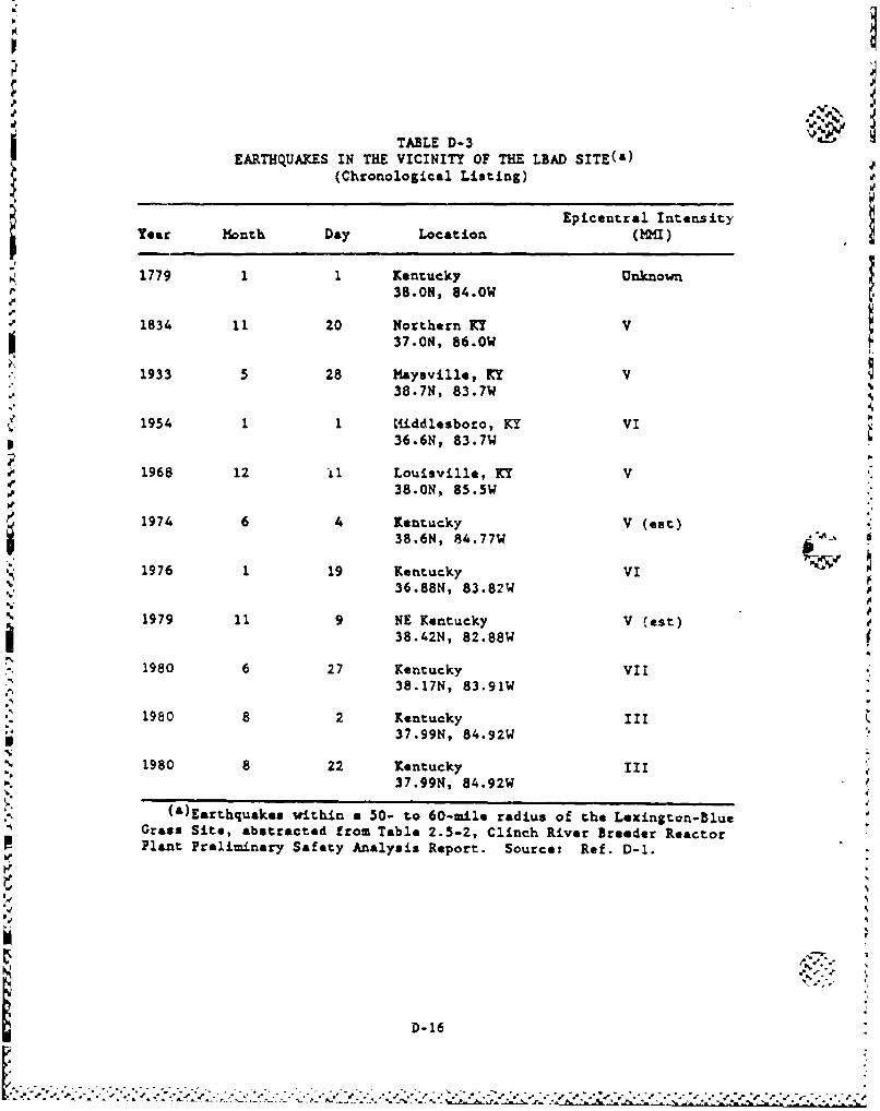
TABLE D-3 dEARTHQUAKES IN THE VICINITY OF THE LBAD SITE(a)
(Chronological Listing)
Epicentral IntensityYear Month Day Location ( MI)
1779 1 1 Kentucky Unknown38.0N, 84.0W
1834 11 20 Northern KY V37.ON, 86.0W
1933 5 28 Maysville, KY V38.7N, 83.7W
1954 11 Middlesboro, KY VI36.6N, 83.7W
1968 12 ii Louisville, KY V.7 K38.ON, 85.5W
1974 6 4 Kentucky V (eat)38.6N, 84.77W
1976 1 19 Kentucky VI% 36.88N, 83.82W
N;N
S1979 11 9 NE Kentucky V (est)
38.42N, 82.88W
1980 6 27 Kentucky VII38.17N, 83.91W
1980 8 2 Kentucky III37.99N, 84.92W
1980 8 22 Kentucky III37.99N, 84.92W
(a)Earthquakes within a 50- to 60-mile radius of the Lexington-BlueGrass Site, abstracted from Table 2.5-2, Clinch River Breeder ReactorPlant Preliminary Safety Analysis Report. Source: Ref. D-1.
'd.'
D-16
. ..... .. . ... ...... . .
Ar
There is a U.S. Air Force radar boebing/scocing detachment at&-
tioned at the LBAD with frequent flights (10 to 11 aircraft per day)
of Air Force B-52, F-4, and F-ill aircraft at low altitudes (750 and
3000 ft). The flights are active from 11:30 AM to 3:30 PM and from
6:00 PM until midnight every day. They fly at 750 ft under visual
I flight rules and at 2000 to 3000 ft under instrument rules with a visual
observer. Generally, they make three sinmlated bombing runs per flight
at distances at least 2 miles away from the chemical exclusion area.Per the guidelines of Ref. D-3, this is not expected to be a significant
problem.
p.•
L4
p.-.
D-17
-Z!CZ< ZI
i.
-h. . S,•
D.1.4. NEWPORT ARMY AMMUNITION PLANT
The Newport Army Ammunition Plant (NAAP) is located in west central
Indiana, west of Indianapolis, as shown in Figs. D-8 and D-9. NAAP is
operated by Mason & Hangar. The mission of NAAP is to (1) manufacture
explosive and chemical materials, (2) fill chemical munitions, and
(3) to store chemical munitions. Items 1 and 2 are currently inactive,
while item 3 involves the activities associated with storage of VX %
chemical agent ton containers.
The chemical storage area at NAAP includes a single storage ware-
house (Building 144) that is used to house VX ton containers. The stor-
age building is approximately 79 ft wide and 279 ft long. The walls and
roof of the building are of heavy gauge corrugated sheet metal, sup-
ported by steel beams.
The warehouse is in an exclusion area adjacent to the former VX. -
production facility. The grounds within the exclusion area are all con-
crete or macadam covered surfaces. There are several large storage
tanks that were used to store agent which are located along the south-
east side of the warehouse. These storage tanks are currently empty.
A 409-ft tall flash tower is located 450 ft to the east of Building 144.
The flash tower was utilized during production of VX to burn several
flammable gas by-products. Just outside the exclusion area, approxi-
metely 560 ft to the east of Building 144, is the site of a natural gas
metering station. Natural gas was distributed to the production plant
and to the area boiler from this point. Several empty storage vessels
are located approximately 350 ft from the nearest ton containers outside 0.
the exclusion area. These tanks ware used in conjunction with the
former VX production facility. These tanks are to remain empty during
the demilitarization campaign.
-- a
Table D-4 summarizes ecrthquake activity in the vicinity of the
NA.AP site. '*
.%*,-
D-18 k-
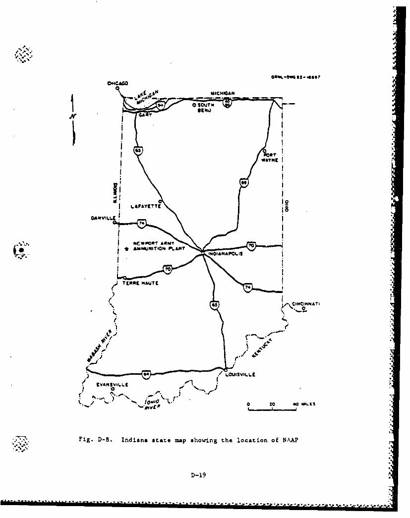
e%
,' .,A
MIHIA
/ (ANSVI.LA
Nc0wradrM~mT tM
I- ~ ~ T9* HAUTE%%%% ~ i~
Fig. D-8. Indiana state map showing the location of NAAP
D-19
............-.- t.. 4s -- ~a
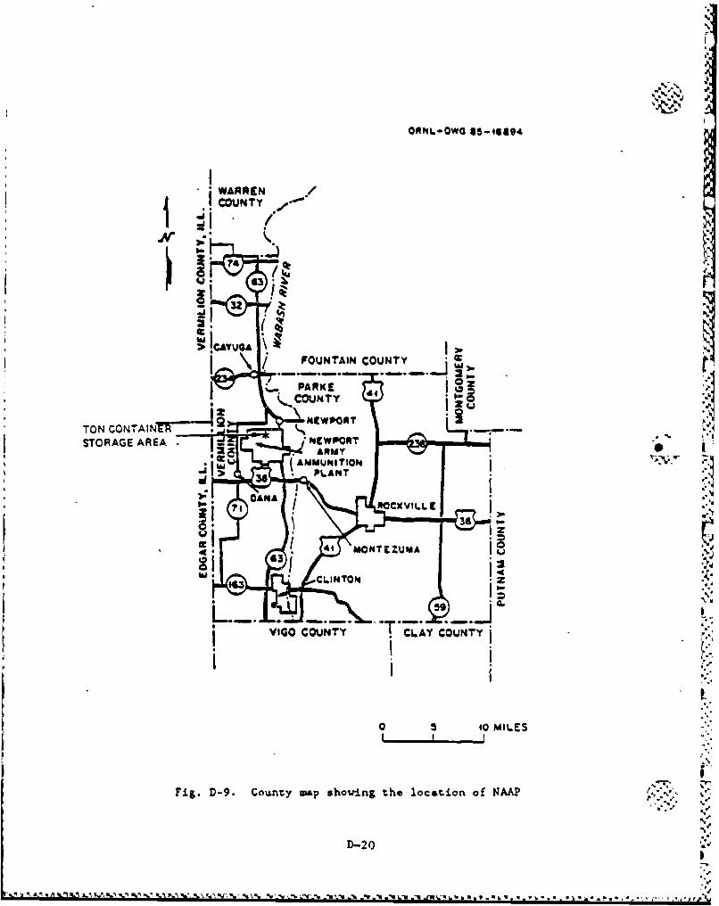
ORNI.-OW0 45-14a,4
WAPPENCOUNTY
43~
2.11CAYU4A \/ FOUNTAIN COUNTY ti
yCOU NT Y
TON CONTAI! 4-
STORAGE'AREA AM
CPLACONT
36 . IL~14A
Fig.D-9 Couty ap howig te lcatin o NM
D-0 3 0MIE
-.
The airspace at NAAP is not restricted. The only airport within a b
10-mi. radius of the plant is a private airstrip (Rowe) with a 2600-ft
runway located 8 miles west of the plast. The nearest public airport is
Clinton which is approximately 12 miles south of the plant. Low alti-
tude federal airway V171 passes 2 miles east of the storage area and
airway V434 passes 5 miles north of the storage area. High altitude
Jet routes JBO and J73 cross over the storage area.
D-21
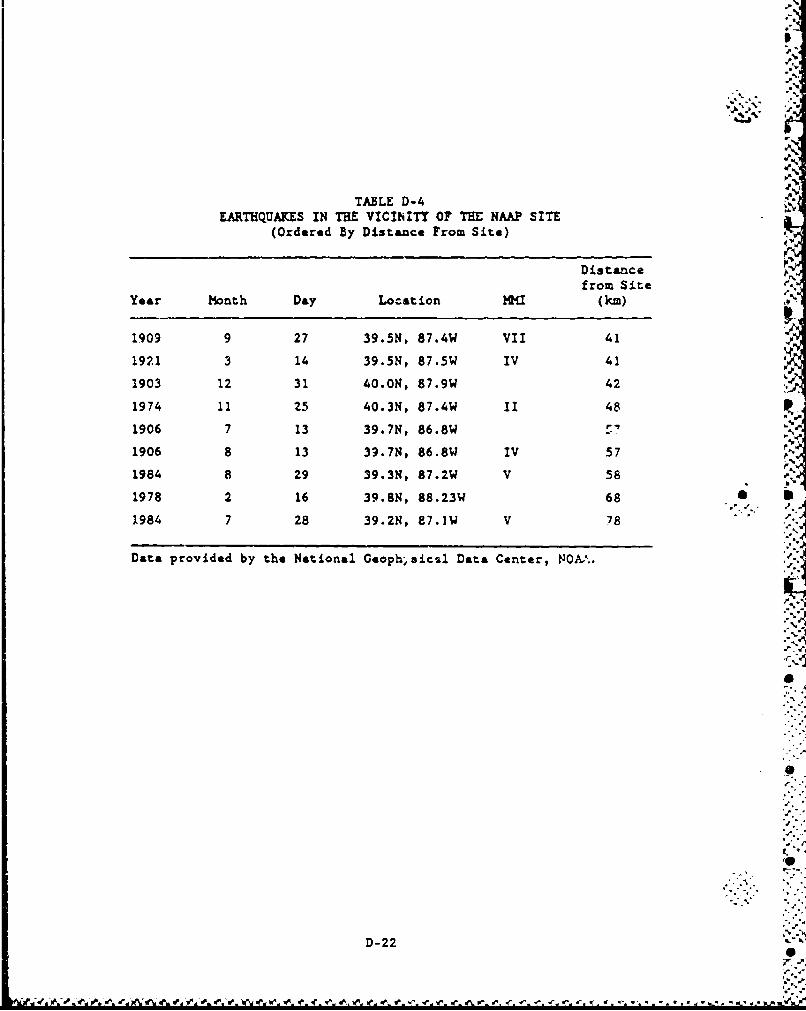
TABLE D-4EARTHQUAKES IN THE VICINITY OF THE NAAP SITE
(Ordered By Distance From Site)
Distancefrom Site
Year Month Day Location HM (km)
1909 9 27 39.5N, 87.4W VII 41
192.1 3 14 39.5N, 87.5W IV 41
1903 12 31 40.ON, 87.9W 42
1974 11 Z5 40.3N, 87.4W 1I 48
1906 7 13 39.7N, 86.8W/£
1906 8 13 39.7N, 86.8W IV 57
1984 8 Z9 39.3N, 87.2W V 58
1978 2 16 39.8N, 88.23W 68
1984 7 28 39.2N, 87.1lW V 78
Data provided by the National Geoph>8icsl Data Center, NOA%..
D-22
-Fd-Nw'% a Or INIrv . 10 d.
D-1.5. PINE BLUFF ARSENAL
As shown in Figs. D-10 and D-l1, the Pine Bluff Arsenal (PBA) isL located southeast of Little Rock, Arkansas and northwest of the city of
* Pine Bluff, Arkarias. The primary missions include storage of conven-
tional and chemical munitions, destruction of nontoxic chemicals, and
p roduction of saoke munitions, white phosphorus projectiles and other
incendiary devices. Future respornsibili;ies include demilitarizetion
of the BZ stockpile and production of binary chemical -u-nitionr.
The chemical sto-age area at PBA is located in the northwesttsen
section of the installation. The fol•owing nmuitions are stored at PBA:
4.2-in. mortar projectiles, H55 rockets, land miner, and ton containers.All u1nitions except ton containers arte stored in 80-ft !%loos. Ton
containers containing uastard agent are stored outdoors in a fenced area
within the rthemical storage area. The ton containers are strapped to
rail-oa$ rails and stacked one high per AMC regulations.
Table D-5 sua.arizes earthquake activity in the vicinity of the PEA
site.
PBA airspace is not restricted. The closest important airfield,
Grider Field, is about 16 miles southeast of the chemical munition stor-
age area. There are three smaller airfields which are closer (10 to
14 miles). Because of the relatively significant distances from air-fields, PBA is not considered to have a significant hazard due to
airfield operations.
Grider handles approximately 115 aircraft movements per day, sevenp days a week. About 95% of this traffic is corporate/civilian, and the
remainder is military. The runway at Grider Field is 6,000 ft and can
occasionally acco date co-ercial 727 and military C-141 aircraft.
Low altitude federal airways V74, V305, and V16 pass within 7, 10, and .,6.t11 miles, respectively. High altitude airway J42 passes over the sitC.
D-23
d J. *I.. .* R * ..j. .-A*. ~
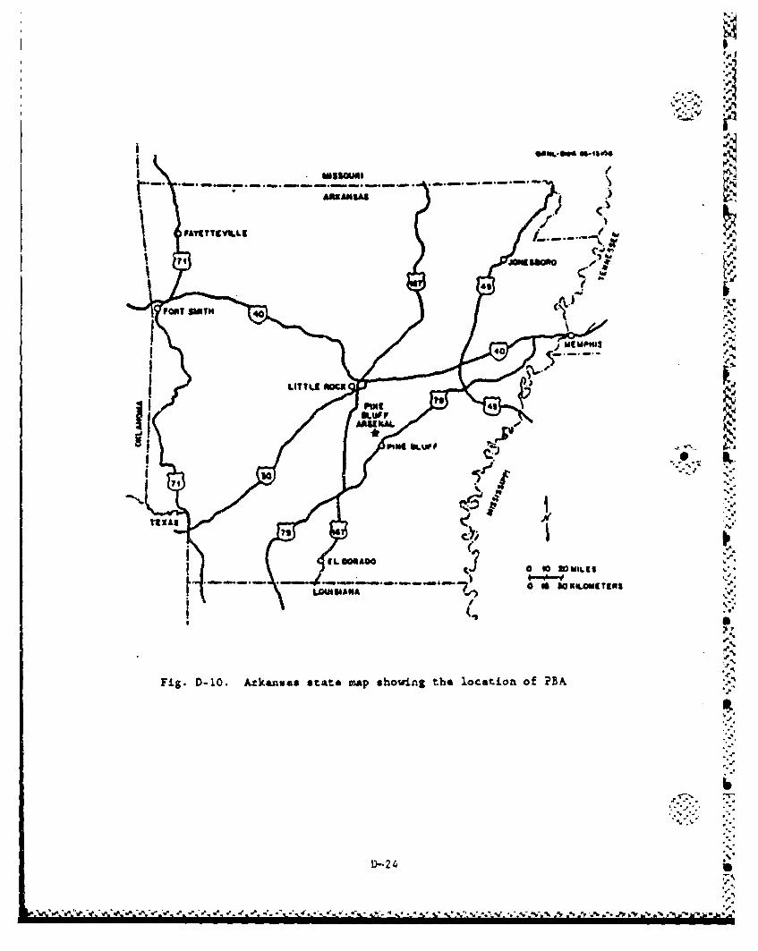
011'
-. j ME ANSA
U~LITTLE O=
PIPE, 4
9LUp.
AAUV-L
91~~~ plt ,.
ToI
0A AwlI.I
Fig. D-10. Atkeanuaa state mAp showing the location of PEA
D-2 4
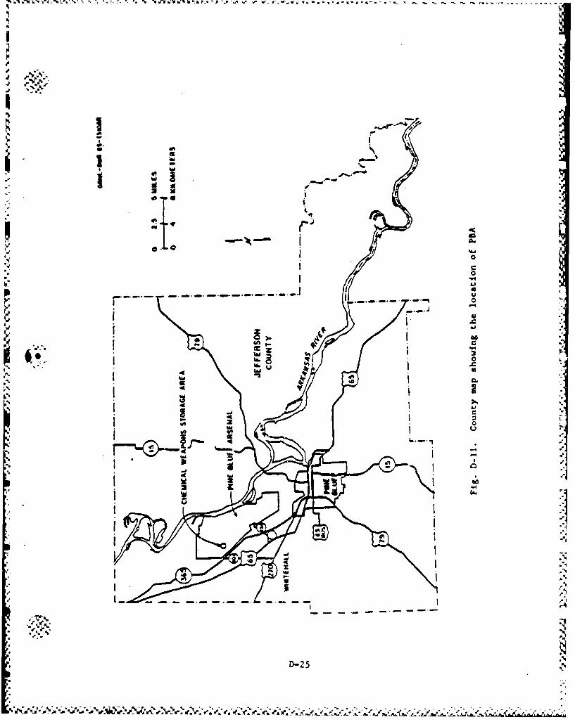
• mll • V z•%• • , • .o -" 61 v W. hrl'•l' 1f,h Yý Y% -L -~ -- -, -. -°• -• -~ - - -' -t '
40
io
D-
I L '
g .. . . . .. .... . .
III- ".S:.:' ,I1 -2-.-
•t•"•t,",';.•/t; •, :••N .'•" 2, ,) .• "-"- "- -" - " "-". .. "' " ". .. " " "' " " " "" "" . . .'
There is a helipad ons ite abouit 2 miles •aya from the them~icel h•anition scarag. area boundary. The flight freqiency was estimated to ,
be 30 or less flights a month (Ref. D-l). q
-'S.-
S ,
'.•
s..
D -26 "
S, %,,,"
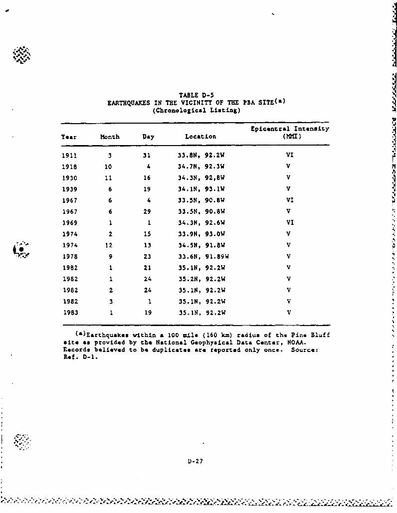
TABLE D-5EARTHQUAKES IN THE VICINITY OF THE PBA SITE(a)
(Chronological Listing)
Epicentral IntensityYear Month Day Location (MMI)
1911 3 31 33.8N, 92.2W VI
1918 10 4 34.7N, 92.3W V
1930 11 16 34.3N, 92,8W V
1939 6 19 34.1N, 93.1W V
1967 6 4 33.5N, 90.8W VI
1967 6 29 33.5N, 90.8W V
1969 1 1 34.3N, 92.6W VI
1974 2 15 33.9N, 93.0W V
1974 12 13 34.5N, 91.8W V
1978 9 23 33.6N, 91.89W V
1982 1 21 35.1N, 92.2W V
1982 1 24 35.2N, 92.2W V
1982 2 24 35.1N, 92.2W V
1982 3 1 35.1N, 92.2W V
1983 1 19 35.1N, 92.2W V
(a)Earthquakes vithin a 100 mile (160 km) radius of the Pine Bluffsite as provided by the National Geophysical Data Center, NOAA.Decords believed to be duplicates are reported only once. Source:Ref. D-1.
D-27
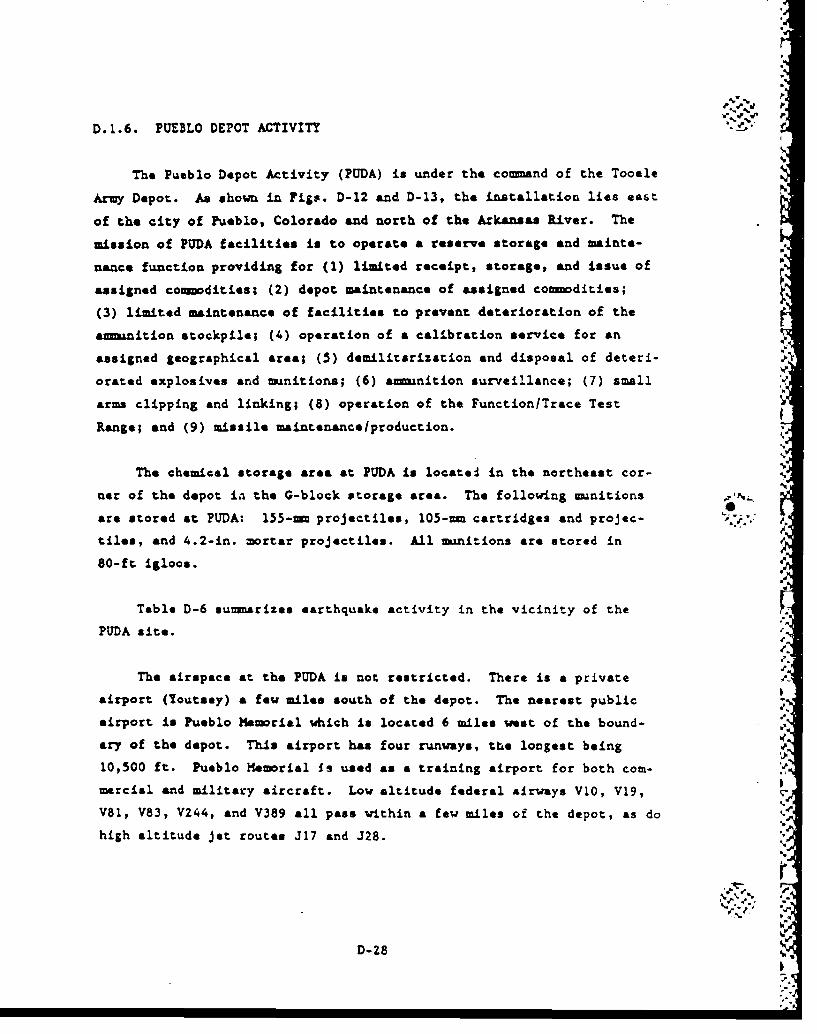
D.1.6. PUEBLO DEPOT ACTIVITY
The Pueblo Depot Activity (PUDA) is under the command of the Tooele
Army Depot. As shown in Figs. D-12 and D-13, the installation lies east.
of the city of Pueblo, Colorado and north of the Arkansas liver. The
mission of PUDA facilities is to operate a reserve storage and mainte-
nance function providing for (1) limited receipt, storage, and issue ofassigned comdities; (2) depot maintenance of assigned co--dities;(3) limited maintenance of facilities to prevent deterioration of the
am-inition stockpile; (4) operation of a calibration service for an
assigned geographical area; (5) demilitarization and disposal of deteri-
orated explosives and -mnitions; (6) ammunition surveillance; (7) small
arms clipping and linking; (8) operation of the Function/Trace Test
Range; and (9) missile maintenance/production.
The chemical storage area at PUDA is located in the northeast cor-
ner of the depot in the G-block storage area. The following munitions
are stored at PUDA: 155-mm projectiles, 105--m cartridges and projec- '.V.,
tiles, and 4.2-in. mortar projectiles. All munitions are stored in
80-ft igloos.
Table D-6 summarizes earthquake activity in the vicinity of the
PUDA site.
The airspace at the PUDA is not restricted. There is a private
airport (Youtsey) a few miles south of the depot. The nearest public
airport is Pueblo Memorial which is located 6 miles waet of the bound-
ary of the depot. This airport has four runways, the longest being '
10,500 ft. Pueblo HMemrial Is used as a training airport for both com-mercial end military aircraft. Low altitude federal airways V10, V19,
V81, V83, V244, and V389 all pass within a few miles of the depot, as do
high altitude jet routes J17 and J28.
D-28-
V.•
P.28F
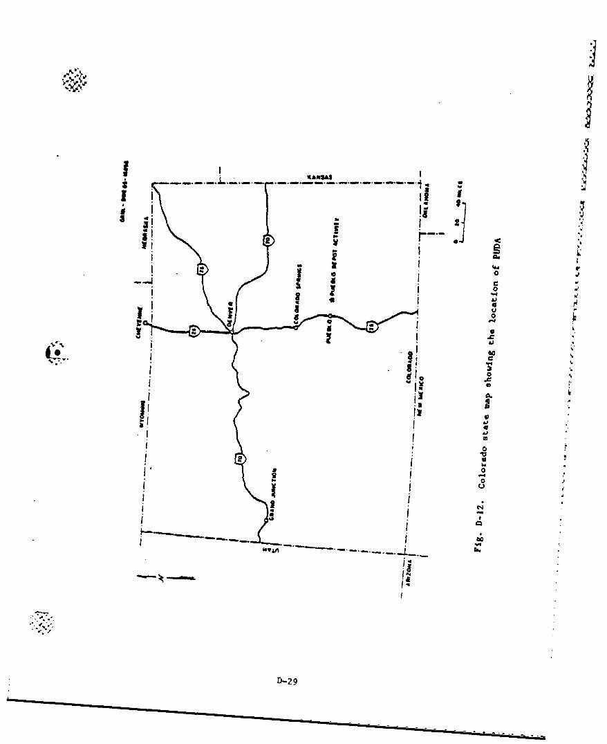
j
I!I.. '.1.13 �t b U *1U -
I i B.
4" a.oa-I e
-40
U
0-4
U
4,
Vo 4,
U
II *1 I.1 0
0. .� *
I, a I a2
Ii4.- ______ I...
I�m
-a..
.4
'a.,
D-2 9
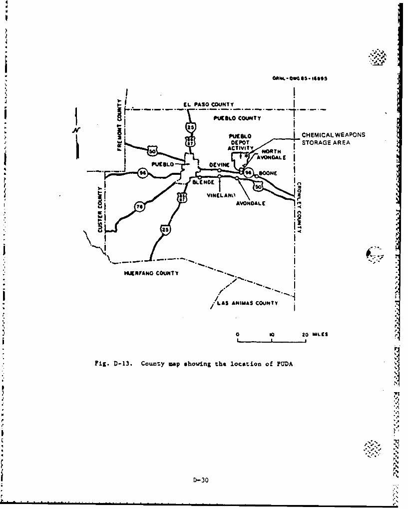
* BGA .-lO as- 49495
CL PASO COUNTYj j j PUCUGLO COUNTY 1
CHEMICAL WEAPONS"DEO ,;,STORAGE AREA50 ACTIVITY NORTm
-. .1 PUC.LO
9 NON
p ~AVONDALE[
t H
HIJERFANO COUNTY "
/ -
LAS ANIMAS COUNTY
0to 0 MIL91SI _ I
Fig. D-13. Coun:y map showing the location of PUDA
IFD,30
-B...
• • _ . . li r.
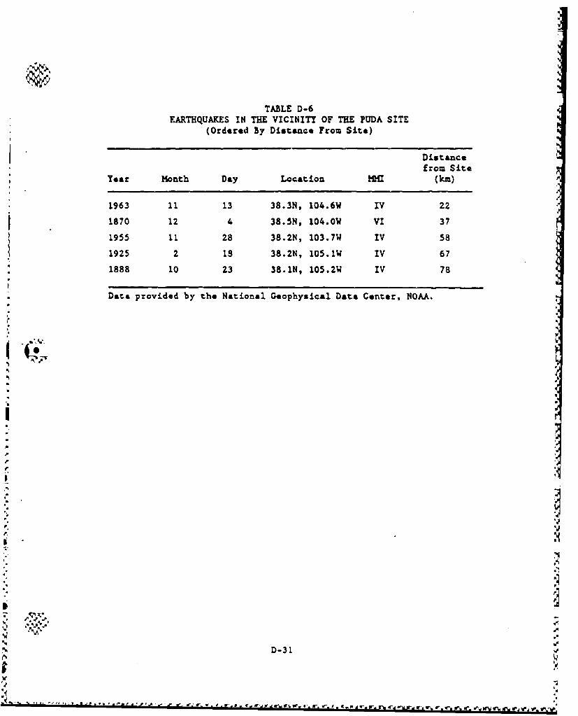
TABLE D-6EARTHQUAKES IN THE VICINITY OF THE PUDA SITE
(Ordered By Distance From Site)
Distancefrom Site
Year Month Day Location M (kim)
1963 11 13 38.3N, 104.6W IV 22
1870 12 4 38.5N, 104.0W VI 37
1955 11 28 38.2N, 103.7W IV 58
1925 2 18 38.2N, 105.1W IV 67
1888 10 23 38.1N, 105.2W IV 78
Data provided by the National Geophysical Data Center, NOAA.
"%I
&
w"I
D.31
Pr. r or
D.7. TOOELE ARMY DEPOT
The Tooele Army Depot (TEAD) is located in north central Utah
southwest of Salt Lake City as shk-.,n in Figs. D-14 and D-15. The Army
Depot consists of two separate areas, North and South. The chemical
agent storage and demilitarization operations are located in the South
Area. The mission of TEAD is to operate a supply depot providing for
receipt, *to-age issue, maintenance and disposal of assigned co'mmdi-
ties; and to operate other facilities such as the Chemical Agent
Munitions Disposal System (CA.DS).
The chemical storage area at TEAD is located in the center of the
south area. There are storage magazines, warehouse buildings, and sev-
eral storage yards within the chemical agent exclusion area. The stor-
age magazines include both 89-ft oval-arch magazines and 80-ft igloo
magazines. H55 rockets, 155--n and 8-in. projectiles, 105--n cartridge
projectiles, 4.2-in. mortar projectiles, GB and VX ton containers, M23
land mines, and weteye bombs are stored in the 80-ft igloos. MC-1..
bombs, 155-rn and 105--- projectiles are stored in the 89-ft oval-arch
magazines. Ton containers containing mustard are stored outdoors. The
two warehouse buildings currently are used to store VX spray tanks
packaged inside THU-28/B storage and shipping containers.
The warehouse buildings are flat-roofed, single-story structures
approximately 188 ft long, 179 ft wide, and 16 ft high. Details of con-
struction are shown in Army Corps of Engineers Drawing 201.-25-65. The
side wells of the buildings are single piece precast concrete panels
in. thick, 16 ft high, with widths varying around 30 ft. The roof is Iof corrugated sheet metal, supported by a steel beam support structureand steel box beam vertical support colums. The main beams are W24 x
68 steel I-beams with unsupported spans of about 30 ft. Open trusses .
are used to span between the miin beams.
D-32.t, kIbt
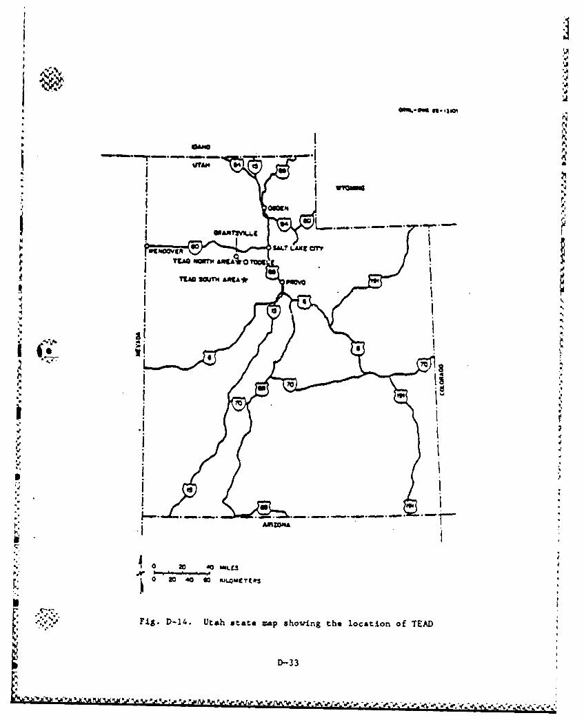
I I
I '.4
D-33
p '
'1 I
, I
Sh I
tII
:5, i '
. ,- I - - . - . . .. . . . . .---
I'..
i •"•'" Ptg. D-14. Utah stat, ,np uhoving the location of TEAD
: I•-3
D-B ' • : - -•#• , ' , , , f , . : v [ , . . % - . r % r . - . . .r _ .• . . 2.- "
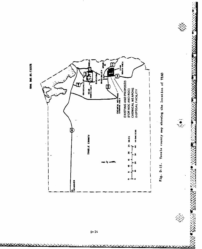
Ile
.000,
IAIV2~
it Z >
cr0dPILI
03 Z-0
m 20
12
lbi
7 'a
AW Table D-7 summarizes earthquake activity in the vicinity of the
TEAD site.
The airspace over the TEAD South Area is not restricted but pilots N.
are requested (for reasons of national security) to ovoid flying below
6400 ft over this area for a radius of 3 nautical miles (3.5 statute
miles).
Tocele Municipal Airport Is the nearest airport to the site. It
is located 14 miles north of the site and is not expected to present a
significant hazard.
There are tu, low altitude federal airways in the vicinity of the
TEAD South Area: V257, three miles to the west, and V253, 17 miles to pthe northeast. High altitude airways are not considered a hazard for
this site.
. There is a helipad located near the administrative building approx-
r imately 3 miles from the chemical minitioon storage area. The helipadis used infrequently. The number of flights per month is estimated to
be 15. N
I
'd.,
D-35
M5~
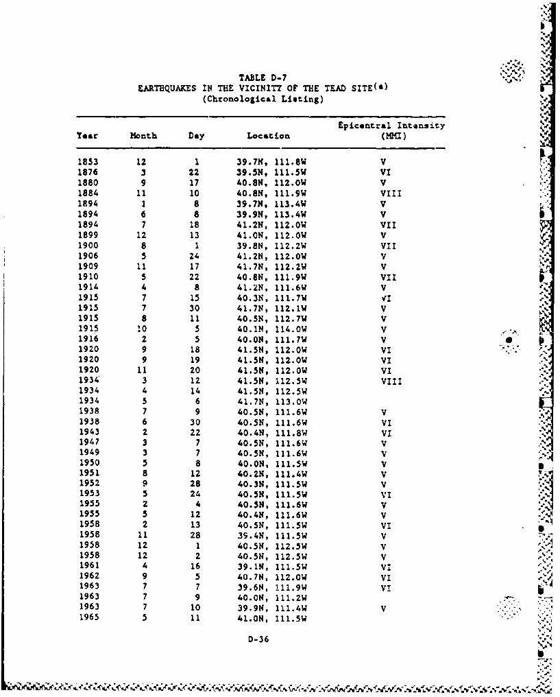
'
TABLE D-7EARTHQUAKES IN THE VICINITY OF THE TEAD SITE(&)
(Chronological Listing)
Epicontral IntensityYear Month Day Location ( MzI)
1853 12 1 39.7N, 111.8W V1876 3 22 39.5N, 111.5W VI1880 9 17 40.8N, 112.0W V1884 11 10 40.8N, 111.9W VIII1894 1 8 39.7N, 113.4W V1894 6 8 39.9N, 113.4W V1894 7 18 41.2N, 112.0W VII1899 12 13 41.0N, 112.0W V1900 8 1 39.8N, 112.2W VII1906 5 24 41.2N, 112.0W V1909 11 17 41.7N, 112.2W V1910 5 22 40.8N, 111.9W VII1914 4 8 41.2N, 111.6W V1915 7 15 40.3N, 111.7W1915 7 30 41.7N, 112.1W V1915 8 11 40.5N, 112.7W V1915 10 5 40.1N, 114.0W V1916 2 5 40.0K, 111.7W V 01920 9 18 41.5N, 112.0W VI .. "1920 9 19 41.5N, 112.0W VI1920 11 20 41.5N, 112.0W VI1934 3 12 41.5N, 112.5W VIII.-%1934 4 14 41.5N, 112.5W1934 5 6 41.7N, 113.0W1938 7 9 40.5N, 111.6W v1938 6 30 40.5K, 111.6W VI1943 2 22 40.4N, 111.8W VI1947 3 7 40.5N, 111.6W V1949 3 7 40.5N, 111.6W V1950 5 8 40.0N, 111.5W V S1951 8 12 40.2N, 111.4W V1952 9 28 40.3N, 111.5W V1953 5 24 40.5N, 111.5W VI1955 2 4 40.5N, 111.6W V1955 5 12 40.4N, 111.6W V1958 2 13 40.5N, 111.5W VI1958 11 28 39.4N, 111.5W V1958 12 1 40.5N, 112.5W V1958 12 2 40.5N, 112.5W V1961 4 16 39.1N, 111.5W VI1962 9 5 40.7N, 112.0W VI1963 7 7 39.6N, 111.9W VI1963 7 9 40.0N, 111.2W .-.1963 7 10 39.9N, 111.4W V1965 5 11 41.0N, 111.5W
D-36
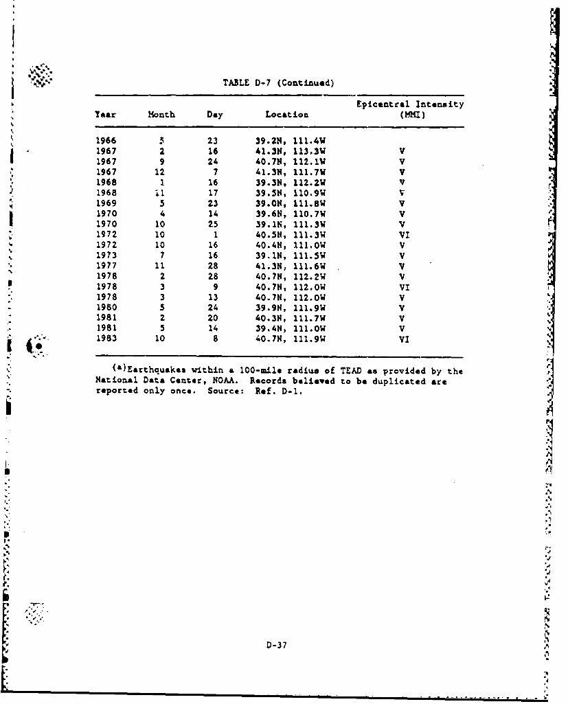
TABLE D-7 (Continued) EI
b ~Epicentral. Intensity•
Year Honth Day Location (MI)
1966 3 23 39.2N, 111.4WI 1967 2 16 41.3N, 113.3W V
1967 9 24 40.7N, 112.1W V1967 12 7 41.3N, 111.7W v1968 1 16 39.31N, 112.2W V1968 i1 17 39.5N, 110.9W v1969 5 23 39.0N, 111.8W V1970 4 14 39.6N, 110.7W V1970 10 25 39.1N, 111.3W V1972 10 1 40.5N, 111.3W VI1972 10 16 40.4N, 111.0W V1973 7 16 39.1N, 111.5W V1977 11 28 41.3N, 111.6W V1978 2 28 40.7N, 112.2W V1978 3 9 40.7N, 112.OW VI1978 3 13 40.7N, 112.0W V1980 5 24 39.9N, 111.9W V1981 2 20 40.3N, 111.7W V •C
1981 5 14 39.4N, 111.0W vS • "" 1983 10 8 40.7N, 111.9W VI
(Earthquakes within a 100-mile radius of TEAD as provided by theNational Data Center, NOAA. Records believed to be duplicated arereported only once. Source: Ref. D-1.
D--
"3S€
.4
........................................... •"l.....i '* r
p%
D.1.8. TIMATILLA DEPOT ACTIVITY
N.K, The Umatilla Depot Activity (UMDA) is under the comman~d of TEAD.
As shown in Figs. D-16 and D-17, the installation is located in Umatilla
and Marrow Counties in northeastern Oregon, near the south shore of the
Columbia River, vast of Hermiston, Oregon. UHDA's mission is to operate
a reserve stor,'ge depot activity under the comand of TEAD providing
care and preservation for and minor maintenance of assigned coodities.
The storage area is located at the northern edge of the instal-
lation. Eighty-foot igloo magazines and warehouses are used to store
the chemical munition stockpile of 155-in and 8-in. projectiles, M55
rockets, 1M23 land mines, bombs, spray tanks, and ton containers. Ware-houses are used to store ton containers containing mistard agent. The
magazines are spaced 400 ft apart.
The warehouses are butler type buildings connected by a roof with a
steel structure and aluminum siding (single sheet). The t buildi.-gs -'"
are defined as transitory structures, approximately 154 ft wide (total
for both buildings) and 300 ft long.
Table D-8 summarizes earthquake activity in the vicinity of the
UMDA site.
The UMDA airspace is not restricted. The nearest active air-
field to the Umatilla site is Hermiston hnnLipal Airport approximately
12 miles from the depot. With one 40C0-ft runway, its capabilities are
limited to aircraft up to the size of corporate jets. The Trn-Cities
Airport in Pasco, Washington, with a maximam runway length of 7700 fc,
is approximately 30 miles from the depot. In general; it does not han-dle military aircraft. There is also a paved runway on the UMDA site
capable of handling small aircraft up to the size of a Beech U-21 light
utility aircraft. The nearest military airfields are in Spokane,
Washington; Moses Lake, Washington; qnd Mt. Home, Idaho. .
I D-38
U,
"N-.e=
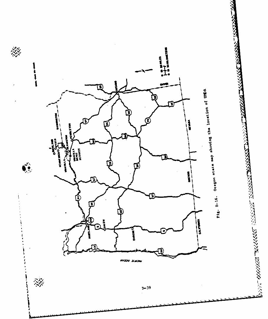
I,,1�
II..
4I I,,
.1
i
oij�iii Cjfk
'I*1*1I�.1,
I..
I
AI
r
I
'4�. D- 39e
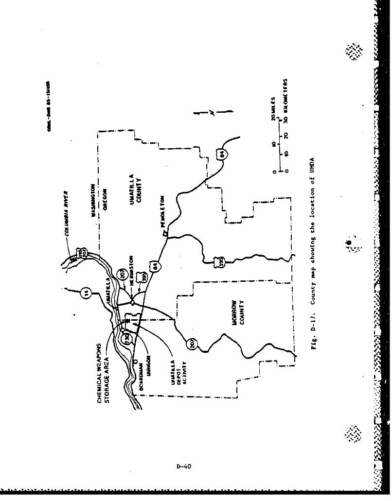
2 I. m
I ---,__ -I ',,1
i 1.. 6~., :.:
SI !I1 , ._jo •4 V
I i '.
*r-- ; . - 'L.."--
0 Z-
I l
-- 0
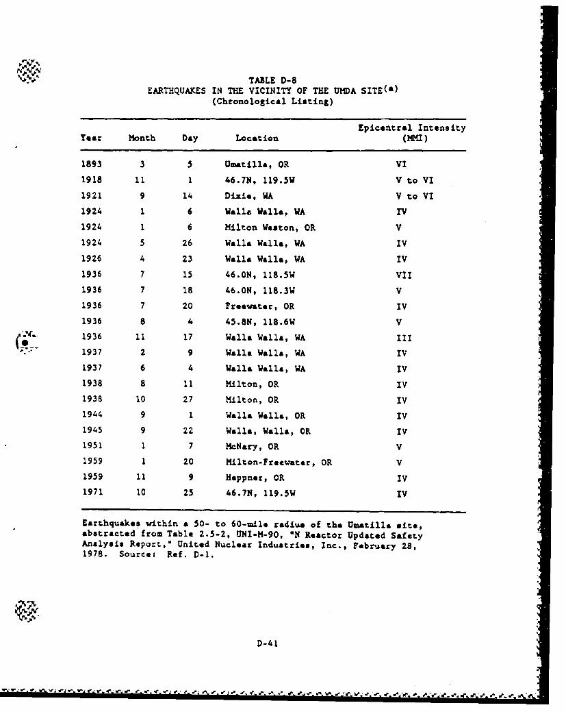
TABLE D-8EARTHQUAKES IN THE VICINITY OF THE UMDA SITE(a)
(Chronological Listing)
Epicentral IntensityYear Month Day Location (MMI)
1893 3 5 Umatilla, OR VI
1918 11 1 46.7N, 119.5W V to VI
1921 9 14 Dixie, WA V to VI
1924 1 6 Walla Walla, WA IV
1924 1 6 Milton Weston, OR V
1924 5 26 Walla Walla, WA IV
1926 4 23 Walla Walla, WA IV
1936 7 15 46.ON, 118.5W VII
1936 7 18 46.0N, 118.3W V
1936 7 20 Freevater, OR IV
1936 8 4 45.8N, 118.6W V
1936 11 17 Walla Walla, WA III1937 2 9 Walla Walls, WA IV
1937 6 4 Walla Walla, WA IV
1938 8 11 Milton, OR IV
1938 10 27 Milton, OR IV
1944 9 1 Walla Walls, OR IV
1945 9 22 Walla, Walla, OR IV
1951 1 7 MNary, OR V
1959 1 20 Milton-Freewater, OR V
1959 11 9 Heppner, OR IV1971 10 25 46.7N, 119.5W IV
Earthquakes within a 50- to 60-mile radius of the Um-atilla site,abstracted from Table 2.5-2, !NI-M-90, "N Reactor Updated SafetyAnalysis Report," United Nuclear Industries, Inc., February 28,1978. Source: Ref. D-1.
D-41
The Medium Attack Tactical Electronic Warfare Wing bombing range is
located 10 miles to the southwst of UMDA chemical munitions exclusion
area. This area is a restricted airspace (Restriction numbers R-5701,
R-5704, R-5706) in twhch the Navy holds bombing exercises. Gruma A-6
aircraft, in groups of four, fly about 14 sorties during the day and
ten sorties at night, five days a week, dropping inert 25-lb bombs and,
occasionally, 500- to 1000-lb inert bombs. Per the guidelines of i
Ref. D-8, this is not considered a significant threat. There are two
low altitude federal airways in the general area of the depot: V-4 and
V-1I2. Three high altitude airways (J-16, J-20, and J-54) cross within
6 miles of the depot toward Pendleton, Oregon.
The installation provides limited maintenance to preclude
deterioration of facilities and retains limited shipping and receiving
capabilities.
Pr
D'-
D- 42
D-1-9. REFERENCES
D-1. Science Applications International Corporation, O?robabiliti~s of
Selected Hazards in Disposition of M55 Rockets," U.S. Arumy Toxic
and Hazardous Materials Agency, 1455-CS-2, November 1985.
D-2. Jeppesen, "United States High Altitude Enroute Charts," U.S. (HI)
1-5, M~arch 1986.
D-3. "Aircraft Hazards," U.S. Nuclear Regulatory Comnission Standard
Review Plan 3.5.1.6, N URE G-0800, Rev 2, July 1981.
D-43
- ." *~ a' .~ * -. , .- d ~*& " "
JV7.V%';' 71.7.7V~j ~ ~ Y~\~~W'P ~~~ F.~ ' ~ ~ J .~d.J ~J
APPENDIX E(Deleted)
APPENDIX FMUNITION FAILURE THRESHOLDS
ir
P-
1-_
,I-
---
S"r
-4~- - v- --
0r
F.1. MUNITION FAILURE THRESHOLDS
The manition stockpile is comprised of 11 different isnition types.
This appendix contains a description of the physical characteristics of
each munition type, a description of their existing storage configura-
tions, and a description of the munition failure thresholds that are
important for quantifying the agent release associated with each
accident scenario. The failure thresholds discussed herein are the
thresholds for accidental burster detonation, the thermal threshold for
hydraulic rupture of the agent compartment, and the mchanical failure
thresholds which lead to failure of the agent compartmnt.
F.1.1. DESCRIPTION OF CHEMICAL MUNITIONS
4-@ The chemical stockpile is presently made up of the following
-unitLonr-
1. 8-in. artillery projectiles. The 8-in. projectiles are filled
with the nerve, agent either GB or VX. They are stored
without fuzes, but they may be stored with or without
bursters. The 8-in. projectiles are stored on wooden pallets
with six rounds per pallet.
2. 155-em artillery projectiles. The 155--m projectiles may
contain GB, VX, or custard. They are stored without fuzes,
but they may be with or without bursters. The 155-rn projec-
tiles are stored on wooden pallets with eight rounds per
pallet.-J
3. 105--n artillery rounds. The rounds are fiLled with either
mustard or GB. The rounds may be stored as bare projectiles
F-1 1'
.X-\ - A-- ~ . - * * -* *. .--. . . - -. ,%
on wooden pallets, width 24 rounds per pallet, and with 2 pal-
lots buatted together and secured with steel banding, or as
cartridges in fiber tubes, with two tubes in a wooden field
box, and with either 12 or 15 boxes unitized on a skid based
wooden pallet. The cartridges include burster, fuze, car-
tridge case and propellant.
4. 4.2-in. mortar projectiles. All are filled with mustard k
agent. The mortars may be stored with burster, fuze, and pro-
pellant in fiber tubes, with two tubes in a wooden field box,
with either 36 boxes on a wooden pallet, or 24 boxes on a
wooden skid base. The mortars may also be stored without
burster and fuze in wooden pellets.
5. M23 land mines. All land mines are filled with VX. The mines
are burstered, and are packaged three to a steel drum. Mine
activators and fuzes are packaged separately in the same drum.
Twelvu drums are contained on a wooden pallet.
6. M55 rockets. The M55 rockets are filled with either GB or VX. .
The rockets are equipped with fuzes and bursters which contain A.
explosives. Propellant is also built into the motor of the
rocket. The rocket casing is made of aluminum which may t,
slowly react with nerve agent to form hydrogen gas. Pressure
buildup in some of the rockets has caused a leakage problem.
The rockets *re individually packaged in fiberglass shipping
tubes with metal and caps. Fifteen containers with rockets
are packed on a wooden pallet.
7. MC-1 750-lb bombs filled with GB. The MC-1 bombs are stored t
without explosive components on wooden pallets with two bombs
per pallet.
7-2
8. MK-94 500-lb bombs filled with GB. The HK-94 bombs are stored
without explosive components in individual MK-410 storage and
shipping containers.
9. MK-116 (Weteyt) 600-lb Navy bombs filled with GB. These bombs
are stored without explosive components in individual ?K-398
storage and shipping containers.
-.4
10. TMI-28/B airborne spray tanks filled with VX. They were
designed for releasing chemical agent from slow-traveling,
low-flying aircraft. The spray tanks are stored in individual
CNU-77/E23 storage and shipping containers.
11. Ton containers. A large fraction of the chemical stockpile is
stored in bulk form in cylindrical steel containers referred
to as ton containers. The ton containers may contain GB, VX,
or mustard. The ton containers are not palletized, but are
banded together in clusters.
Drawings and photographs of each of the above =unitions are shown
in Figs. F-I thzough F-35.
During transportation of the munitions, either to an onsite dis-
posal facility or an offaite disposal facility, the munitions are placed .r
in a protective shipping container or package. The shipping package has
not yet been designed, but criteria for the structural and thermal
protection to be provided during manition transport are defined in
Ref. F-1.
A.
F-3 A;
.............................................
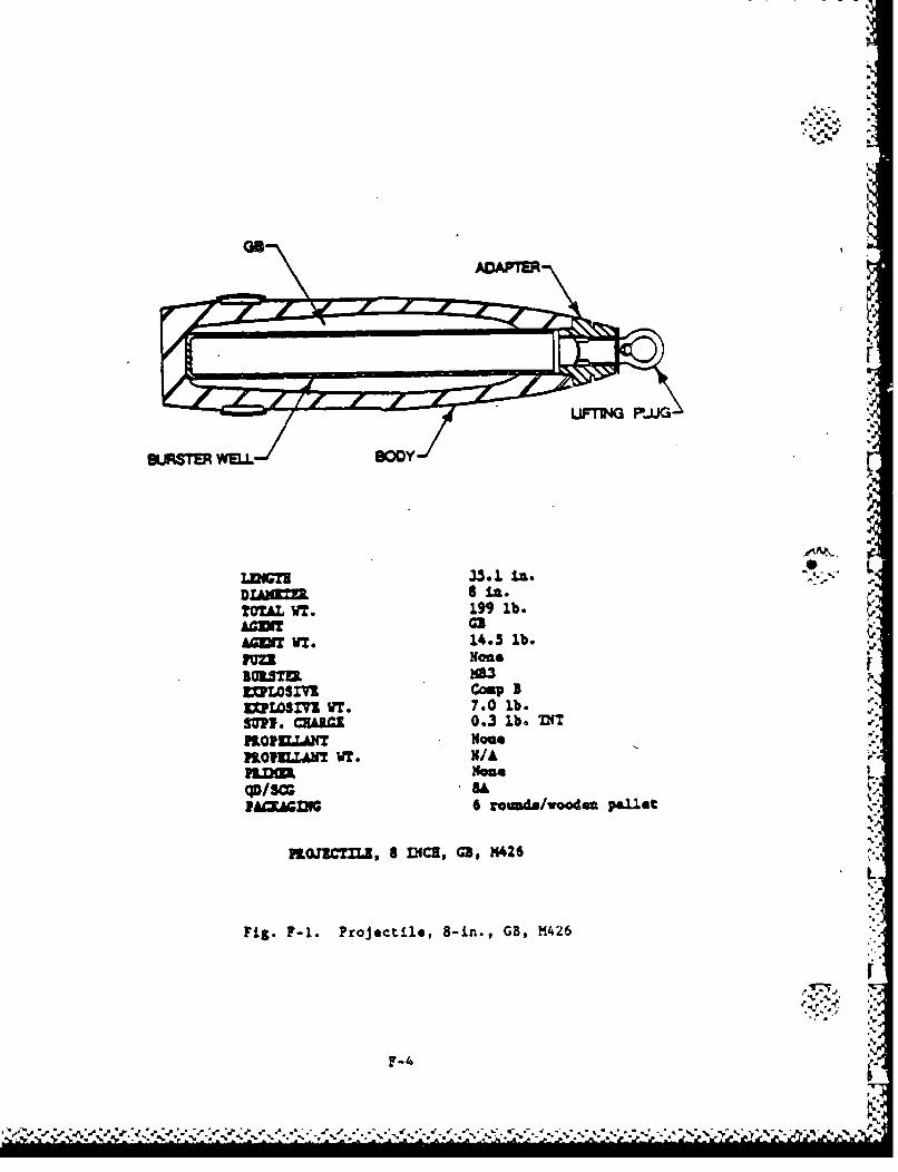
ADAPTER
FrWtbFP-Ut
DIAX=
TO= WT.1" lb.ACM c.AGVIT VT.14.3 lb. -
VUU None
LXWSMV WT. 7. 0 lb.
SUI. CZALGI 0.3 lb. TNTi.-pflOVWLANT None .
PI.OICU.NT WT. N/A F
qD/scrPACFAGfl 6 rouda/vooden pallet %
flOJICTZL, 8 D~IC, G3, M425L
Fig. F-1. Projectile, 8-in., GB, M1426
F-4.