Embed Size (px)
Citation preview
DODGE RAMW1500, W2500 AND W3500
1994 & LATER INSTALLATION INSTRUCTIONS
Model No. 985Mount Assembly Box No. 62035
Hydraulics Box No. 56365Harness Kit No.: 62525, 62917, 63396, 63400, 63402, 63404, 63406
Plug-In Harness for MVP without DRL’s: 62526, 62921, 63398Headlamp Kit No.: 61540, 61550, 66640
WESTERN PRODUCTS, P.O. BOX 245038, MILWAUKEE, WI 53224-9538
FORM NO. 13639May 24, 1999
CAUTIONSee your WESTERN® outlet for applicationrecommendations. The Selection List hasspecific vehicle and snowplow requirements.
A DIVISION OF DOUGLAS DYNAMICS, L.L.C.

TABLE OF CONTENTS
SAFETY . . . . . . . . . . . . . . . . . . . . . . . . . . . . . . . . . . 1
General Safety . . . . . . . . . . . . . . . . . . . . . . . . . . 1
Torque Chart . . . . . . . . . . . . . . . . . . . . . . . . . . . . 1
MOUNT INSTALLATION . . . . . . . . . . . . . . . . . . . . . 2
Mount Frame . . . . . . . . . . . . . . . . . . . . . . . . . . . 2
Spreader . . . . . . . . . . . . . . . . . . . . . . . . . . . . . . . 2
Thrust Arms . . . . . . . . . . . . . . . . . . . . . . . . . . . . 2
Thrust Frame . . . . . . . . . . . . . . . . . . . . . . . . . . . 4
Brace . . . . . . . . . . . . . . . . . . . . . . . . . . . . . . . . . 4
Link Arms . . . . . . . . . . . . . . . . . . . . . . . . . . . . . . 4
Harness Kit Selection . . . . . . . . . . . . . . . . . . . . . 4
SOLENOID CONTROL INSTALLATION . . . . . . . . . 5
Solenoid Control - Floor MountedInstallation Instructions . . . . . . . . . . . . . . . . . . . 5
UNDER HOOD INSTALLATION . . . . . . . . . . . . . . . . 6
Vehicle Harness and Motor Relay . . . . . . . . . . . . 6
Form No. 13639 May 24,1999
PLUG-IN HARNESS AND HEADLAMP RELAYINSTALLATION . . . . . . . . . . . . . . . . . . . . . . . . . 9
Vehicle Headlamp Plug-In Harness andHeadlamp Relays . . . . . . . . . . . . . . . . . . . . . 9
OPERATIONAL TESTS AND ADJUSTMENTS . . . 10
Filing Hydraulic Unit . . . . . . . . . . . . . . . . . . . . . 10
Blade Drop Speed Adjustment . . . . . . . . . . . . . 11
Final Hydraulic Inspection . . . . . . . . . . . . . . . . . 11
Coupling Lug Height Check . . . . . . . . . . . . . . . 11
Vehicle Lighting Check . . . . . . . . . . . . . . . . . . . 12
WIRING DIAGRAM WITHOUT DRL’S(1998 & Earlier) . . . . . . . . . . . . . . . . . . . . . . . . . . 13
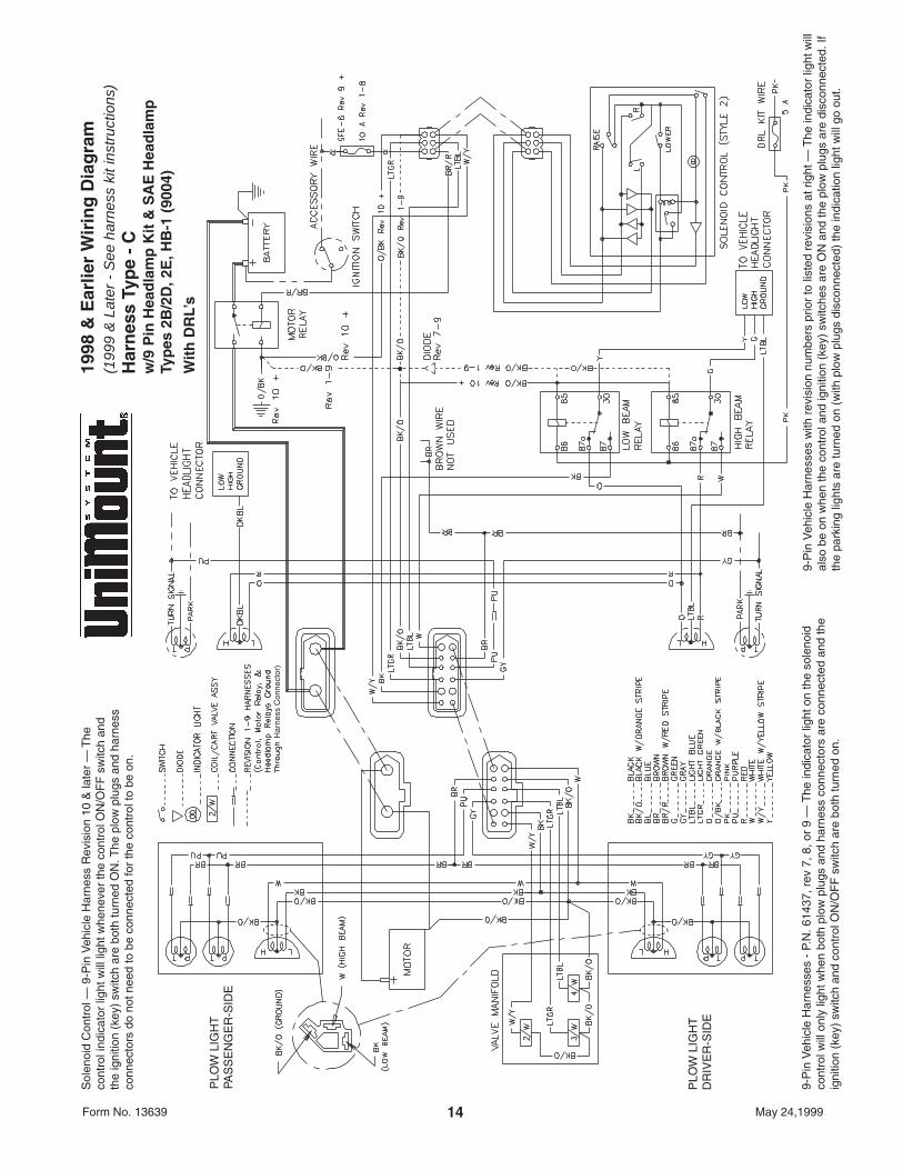
WIRING DIAGRAM WITH DRL’S(1998 & Earlier) . . . . . . . . . . . . . . . . . . . . . . . . . . 14
ASSEMBLY DIAGRAM . . . . . . . . . . . . . . . . . . . . . . 15
1Form No. 13639 May 24,1999
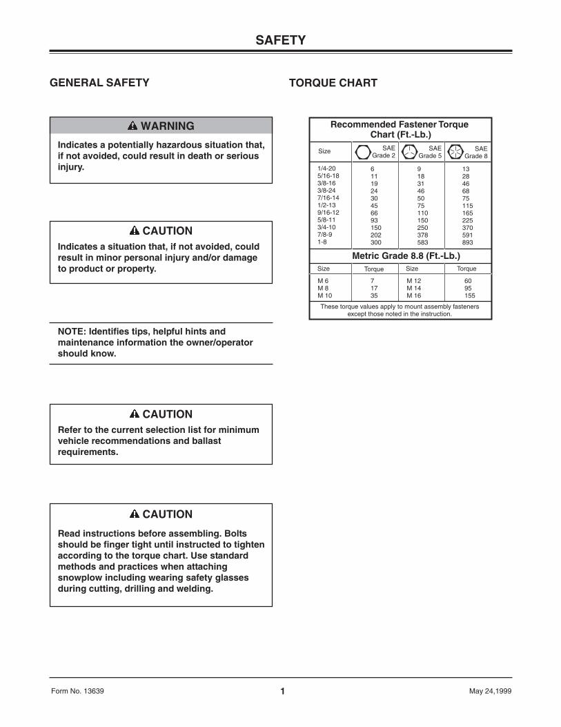
NOTE: Identifies tips, helpful hints andmaintenance information the owner/operatorshould know.
SAFETY
CAUTIONRefer to the current selection list for minimumvehicle recommendations and ballastrequirements.
GENERAL SAFETY
WARNING
Indicates a potentially hazardous situation that,if not avoided, could result in death or seriousinjury.
CAUTION
Read instructions before assembling. Boltsshould be finger tight until instructed to tightenaccording to the torque chart. Use standardmethods and practices when attachingsnowplow including wearing safety glassesduring cutting, drilling and welding.
CAUTIONIndicates a situation that, if not avoided, couldresult in minor personal injury and/or damageto product or property.
Recommended Fastener Torque Chart (Ft.-Lb.)
Size SAEGrade 2
SAEGrade 5
SAEGrade 8
1/4-205/16-183/8-163/8-247/16-141/2-139/16-125/8-113/4-107/8-91-8
611192430456693150202300
91831465075110150250378583
1328466875115165225370591893
Metric Grade 8.8 (Ft.-Lb.)Size TorqueSizeTorque
M 6M 8M 10
M 12M 14M 16
71735
6095155
These torque values apply to mount assembly fastenersexcept those noted in the instruction.
TORQUE CHART
2Form No. 13639 May 24,1999
MOUNT FRAME1. Remove air dam, tow hooks and tow hook
brackets. On each side, remove three bumpermounting fasteners from vehicle frame horn.
2. Install mount frame to outside of vehicle framehorns, aligning two small holes in each side plateto lower bumper bracket holes.
3. 1994-1996 models: Insert a bolt assembly intothe long slot in the inner face of each vehicleframe horn and through the large hole in mountframe side plates. Retain each bolt assembly witha 5/8" locknut. Reinstall original bumper fasteners.Install all fasteners from inside of vehicle frametowards outside.
1997 Chassis cab only and 1998 and latermodels: Install the nut bar (Item 11 on Parts List)through the square hole in the frame at thebumper brace.
March 1999 and later models: Usinghole in mount as a guide, ream hole inframe to 5/8”. Assemble a 5/8" hex capscrew with lock washer through the mountframe end plate hole into the nut bar.
MOUNT INSTALLATION
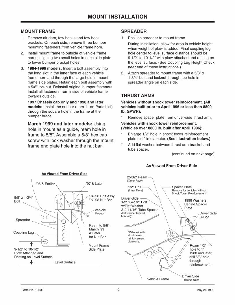
5/8" x 1-3/4"Bolt
Spreader
Coupling Lug
9-1/2" to 10-1/2" Plow Attached and Resting on Level Surface
Level Surface
Mount FrameSide Plate
Ream to 5/8"March '99 & Later for Nut Bar
Vehicle Frame
'94-'96 Bolt Assy'97-'98 Nut Bar
'97 & Later'96 & Earlier
As Viewed From Driver Side25/32" Ream (Outer Face)
1/2" Drill (Inner Face)
Driver-Side1/2" x 4-1/2" Bolt w/Flat Washer & 2-11/16" Tube Spacer (flat washer behind bracket)*
Vehicle FrameDriver SideThrust Arm
Spacer PlateRemove for vehicles withoutShock Tower Reinforcement
1998 WashersBehind Spacer Plate
Driver SideU-Bolt
Ream 1/2" hole to 1"1988 and later,drill 5/8" hole throughreinforcement.
*Vehicles withshock towerreinforcementplate only.
As Viewed From Driver Side
SPREADER1. Position spreader to mount frame.
During installation, allow for drop in vehicle heightwhen weight of plow is added. Final coupling lughole center to level surface distance should be9-1/2" to 10-1/2" with plow attached and resting onthe level surface. (See Coupling Lug Height Checknear end of these instructions.)
2. Attach spreader to mount frame with a 5/8" x1-3/4" bolt and locknut through top hole inspreader angle on each side.
THRUST ARMSVehicles without shock tower reinforcement. (Allvehicles built prior to April 1996 or less than 8800lb. GVWR):
* Remove spacer plate from driver-side thrust arm.
Vehicles with shock tower reinforcement.(Vehicles over 8800 lb. built after April 1996):
* Enlarge 1/2" hole in shock tower reinforcementplate to 1" in diameter. (See illustration below.)
* Add flat washer between thrust arm bracket andtube spacer.
(continued on next page)
3Form No. 13639 May 24,1999
MOUNT INSTALLATION
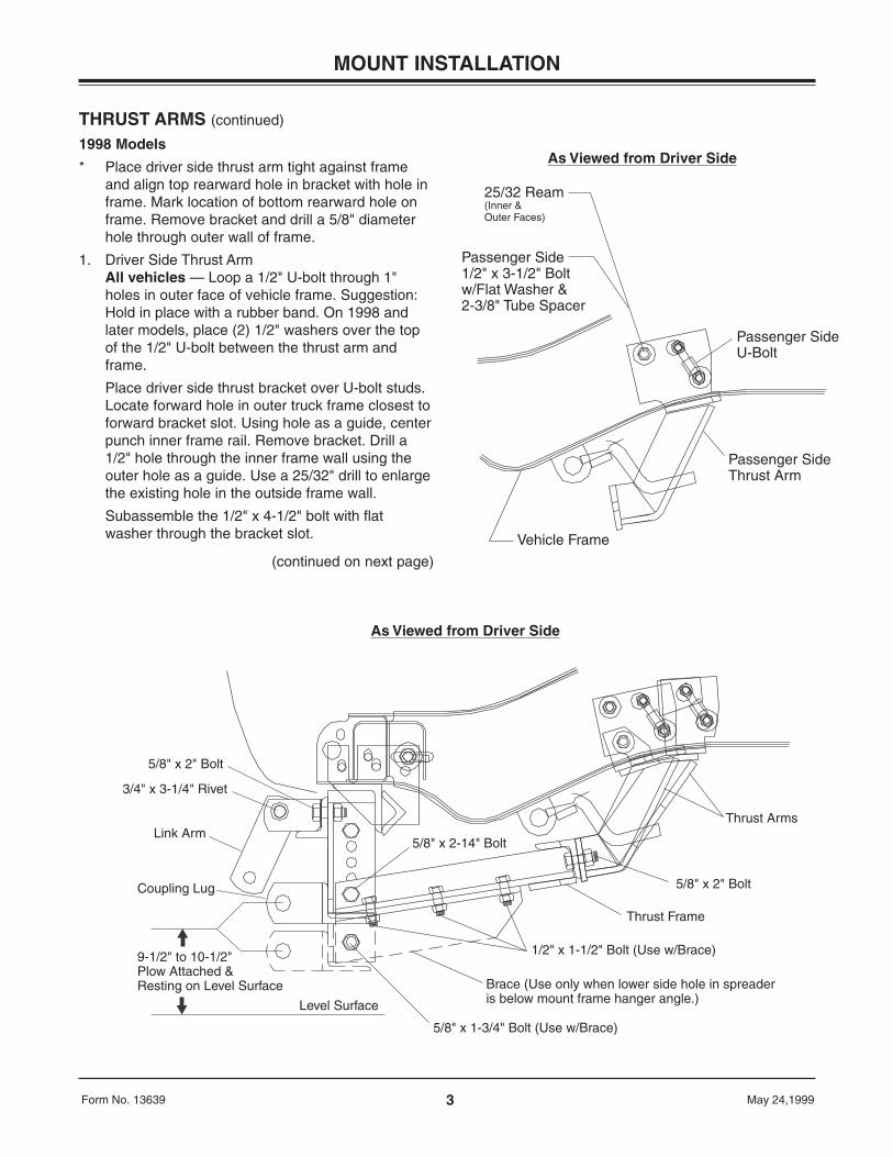
5/8" x 2" Bolt
3/4" x 3-1/4" Rivet
Link Arm
Coupling Lug
9-1/2" to 10-1/2"Plow Attached &Resting on Level Surface
Level Surface
5/8" x 1-3/4" Bolt (Use w/Brace)
Brace (Use only when lower side hole in spreader is below mount frame hanger angle.)
Thrust Frame
5/8" x 2" Bolt
Thrust Arms
5/8" x 2-14" Bolt
1/2" x 1-1/2" Bolt (Use w/Brace)
As Viewed from Driver Side
THRUST ARMS (continued)
1998 Models
* Place driver side thrust arm tight against frameand align top rearward hole in bracket with hole inframe. Mark location of bottom rearward hole onframe. Remove bracket and drill a 5/8" diameterhole through outer wall of frame.
1. Driver Side Thrust ArmAll vehicles — Loop a 1/2" U-bolt through 1"holes in outer face of vehicle frame. Suggestion:Hold in place with a rubber band. On 1998 andlater models, place (2) 1/2" washers over the topof the 1/2" U-bolt between the thrust arm andframe.
Place driver side thrust bracket over U-bolt studs.Locate forward hole in outer truck frame closest toforward bracket slot. Using hole as a guide, centerpunch inner frame rail. Remove bracket. Drill a1/2" hole through the inner frame wall using theouter hole as a guide. Use a 25/32" drill to enlargethe existing hole in the outside frame wall.
Subassemble the 1/2" x 4-1/2" bolt with flatwasher through the bracket slot.
(continued on next page)
25/32 Ream (Inner & Outer Faces)
Passenger Side 1/2" x 3-1/2" Bolt w/Flat Washer & 2-3/8" Tube Spacer
Vehicle Frame
Passenger Side Thrust Arm
Passenger SideU-Bolt
As Viewed from Driver Side
4Form No. 13639 May 24,1999
MOUNT INSTALLATION
THRUST ARMS (continued)
NOTE: Vehicles with shock tower reinforcementplate, install a flat washer on bolt prior toinstalling tube spacer. Assemble the 2-11/16"tube spacer over the bolt. Insert the thrust armwith the bolt and spacer into the 25/32" hole.Position rear holes of thrust arm bracket overU-bolt. Retain with a locknut on upper stud anda flat washer and locknut on lower stud. Secure1/2" x 4-1/2" bolt with nut and washer.
Hold thrust arm tight to bottom of vehicle frameand push towards rear. Tighten locknuts to 75 ft. lb.
2. Passenger Side Thrust ArmDiesel Engine Vehicles - Protect pump on inside ofvehicle frame rail by placing a protective piece ofsteel between the pump and frame rail.
All Vehicles - Ream 18 mm holes in outer andinner faces of vehicle frame to 25/32" diameter.
Install U-bolt and attach thrust arm the same as ondriver-side including holding tight to bottom ofvehicle frame while tightening locknuts.
Assemble 1/2" flat washer on to 1/2" x 3-1/2" boltfollowed by 2-3/8" long tube spacer.
From outside of vehicle frame, insert bolt, washerand tube assembly through large hole in thrustarm and reamed holes in vehicle frame.
Secure with a flat washer and locknut.
THRUST FRAME1. Attach thrust frame to thrust arms with two 5/8" x
2" bolts and locknuts.
2. Attach thrust frame to spreader and mount framewith a 5/8" x 2-1/4" bolt and locknut through lowerhole in mount frame.
3. Fasten each side of spreader to front of mountframe through holes located between link arm lugswith a 5/8" x 2" bolt, flat washer to slot, and locknut.
BRACE(Used when lower side hole in spreader is belowmount frame hanger angle.)
1. If spreader position allows, attach each brace tothe underside of each thrust frame angle withthree 1/2" x 1-1/2" bolts and locknuts.
2. Fasten each brace to the lower hole in each sideof spreader with a 5/8" x 1-3/4" bolt and locknut.
Tighten all bolts to corresponding torque chart value.
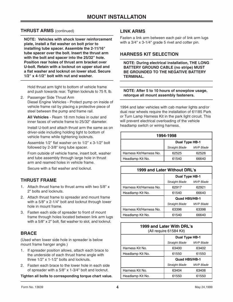
LINK ARMSFasten a link arm between each pair of link arm lugswith a 3/4" x 3-1/4" grade 5 rivet and cotter pin.
HARNESS KIT SELECTION
NOTE: During electrical installation, THE LONGBATTERY GROUND CABLE (no stripe) MUSTBE GROUNDED TO THE NEGATIVE BATTERYTERMINAL.
NOTE: After 5 to 10 hours of snowplow usage,retorque all mount assembly fasteners.
1994 and later vehicles with cab marker lights and/ordual rear wheels require the installation of 61185 Parkor Turn Lamp Harness Kit in the park light circuit. Thiswill prevent electrical overloading of the vehicleheadlamp switch or wiring harness.
1994-1998Dual Type HB-1
Straight Blade MVP Blade
Harness Kit/Harness No. 62525 62526
Headlamp Kit No. 61540 66640
1999 and Later Without DRL'sDual Type HB-1
Straight Blade MVP Blade
Harness Kit/Harness No. 62917 62921
Headlamp Kit No. 61540 66640
Quad HB5/HB-1
Straight Blade MVP Blade
Harness Kit/Harness No. 63396 63398
Headlamp Kit No. 61540 66640
1999 and Later With DRL's(All require 61584 Kit)
Dual Type HB-1
Straight Blade MVP Blade
Harness Kit No. 63400 63402
Headlamp Kit No. 61550 61550
Quad HB5/HB-1
Straight Blade MVP Blade
Harness Kit No. 63404 63406
Headlamp Kit No. 61550 61550
5Form No. 13639 May 24,1999
SOLENOID CONTROL INSTALLATION
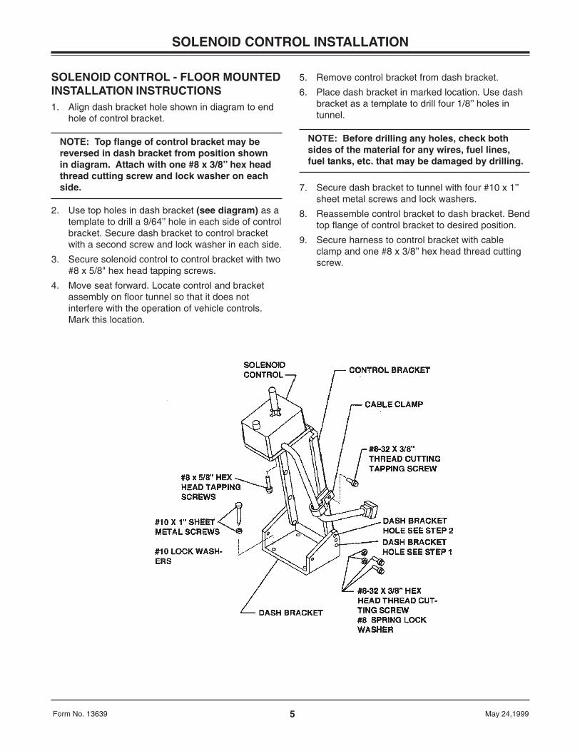
SOLENOID CONTROL - FLOOR MOUNTEDINSTALLATION INSTRUCTIONS1. Align dash bracket hole shown in diagram to end
hole of control bracket.
NOTE: Top flange of control bracket may bereversed in dash bracket from position shownin diagram. Attach with one #8 x 3/8’’ hex headthread cutting screw and lock washer on eachside.
2. Use top holes in dash bracket (see diagram) as atemplate to drill a 9/64’’ hole in each side of controlbracket. Secure dash bracket to control bracketwith a second screw and lock washer in each side.
3. Secure solenoid control to control bracket with two#8 x 5/8" hex head tapping screws.
4. Move seat forward. Locate control and bracketassembly on floor tunnel so that it does notinterfere with the operation of vehicle controls.Mark this location.
5. Remove control bracket from dash bracket.
6. Place dash bracket in marked location. Use dashbracket as a template to drill four 1/8’’ holes intunnel.
NOTE: Before drilling any holes, check bothsides of the material for any wires, fuel lines,fuel tanks, etc. that may be damaged by drilling.
7. Secure dash bracket to tunnel with four #10 x 1’’sheet metal screws and lock washers.
8. Reassemble control bracket to dash bracket. Bendtop flange of control bracket to desired position.
9. Secure harness to control bracket with cableclamp and one #8 x 3/8’’ hex head thread cuttingscrew.
6Form No. 13639 May 24,1999
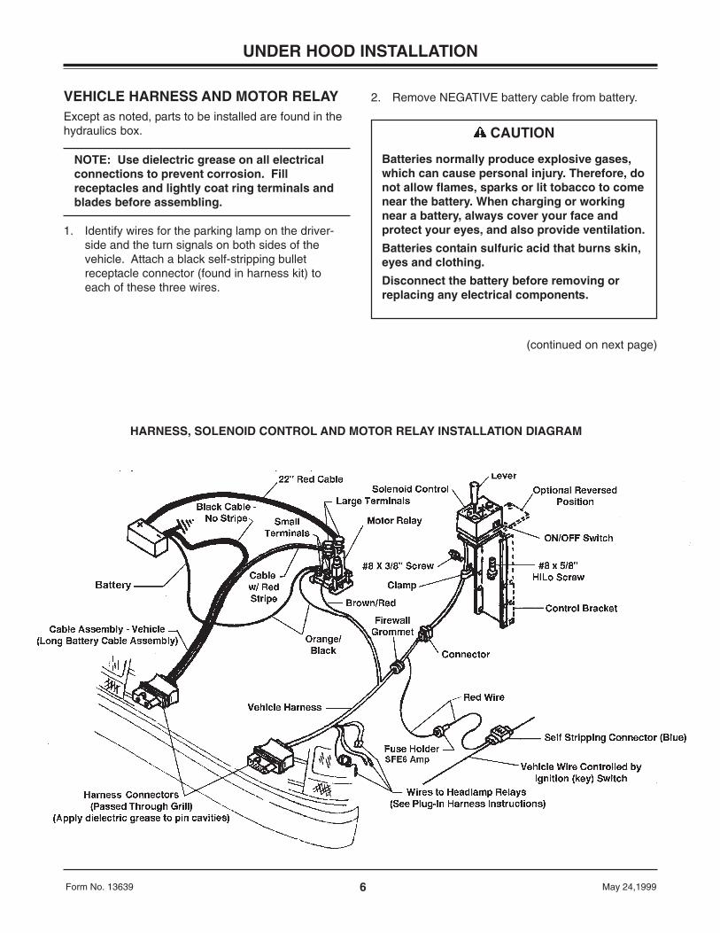
VEHICLE HARNESS AND MOTOR RELAYExcept as noted, parts to be installed are found in thehydraulics box.
NOTE: Use dielectric grease on all electricalconnections to prevent corrosion. Fillreceptacles and lightly coat ring terminals andblades before assembling.
1. Identify wires for the parking lamp on the driver-side and the turn signals on both sides of thevehicle. Attach a black self-stripping bulletreceptacle connector (found in harness kit) toeach of these three wires.
UNDER HOOD INSTALLATION
CAUTION
Batteries normally produce explosive gases,which can cause personal injury. Therefore, donot allow flames, sparks or lit tobacco to comenear the battery. When charging or workingnear a battery, always cover your face andprotect your eyes, and also provide ventilation.
Batteries contain sulfuric acid that burns skin,eyes and clothing.
Disconnect the battery before removing orreplacing any electrical components.
2. Remove NEGATIVE battery cable from battery.
(continued on next page)
HARNESS, SOLENOID CONTROL AND MOTOR RELAY INSTALLATION DIAGRAM
7Form No. 13639 May 24,1999
VEHICLE HARNESS AND MOTOR RELAY (continued)
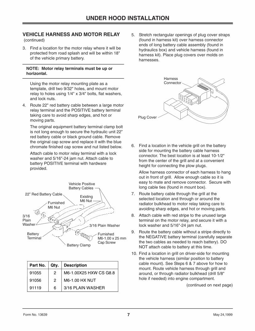
3. Find a location for the motor relay where it will beprotected from road splash and will be within 18"of the vehicle primary battery.
NOTE: Motor relay terminals must be up orhorizontal.
Using the motor relay mounting plate as atemplate, drill two 9/32" holes, and mount motorrelay to holes using 1/4" x 3/4" bolts, flat washers,and lock nuts.
4. Route 22" red battery cable between a large motorrelay terminal and the POSITIVE battery terminaltaking care to avoid sharp edges, and hot ormoving parts.
The original equipment battery terminal clamp boltis not long enough to secure the hydraulic unit 22”red battery cable or black ground cable. Removethe original cap screw and replace it with the bluechromate finished cap screw and nut listed below.
Attach cable to motor relay terminal with a lockwasher and 5/16"-24 jam nut. Attach cable tobattery POSITIVE terminal with hardwareprovided.
6. Find a location in the vehicle grill on the batteryside for mounting the battery cable harnessconnector. The best location is at least 10-1/2"from the center of the grill and at a convenientheight for connecting the plow plugs.
Allow harness connector of each harness to hangout in front of grill. Allow enough cable so it iseasy to mate and remove connector. Secure withlong cable ties (found in mount box).
7. Route battery cable through the grill at theselected location and through or around theradiator bulkhead to motor relay taking care toavoiding sharp edges, and hot or moving parts.
8. Attach cable with red stripe to the unused largeterminal on the motor relay, and secure it with alock washer and 5/16"-24 jam nut.
9. Route the battery cable without a stripe directly tothe NEGATIVE battery terminal (carefully separatethe two cables as needed to reach battery). DONOT attach cable to battery at this time.
10. Find a location in grill on driver-side for mountingthe vehicle harness (similar position to batterycable mount). See Steps 6 & 7 above for how tomount. Route vehicle harness through grill andaround, or through radiator bulkhead (drill 5/8"hole if needed) into engine compartment.
(continued on next page)
Harness Connector
Plug Cover
5. Stretch rectangular openings of plug cover straps(found in harness kit) over harness connectorends of long battery cable assembly (found inhydraulics box) and vehicle harness (found inharness kit). Place plug covers over molds onharnesses.
UNDER HOOD INSTALLATION
Part No. Qty. Description
91055 2 M6-1.00X25 HXW CS G8.8
91056 2 M6-1.00 HX NUT
91119 6 3/16 PLAIN WASHER
22” Red Battery Cable
FurnishedM6 Nut
3/16PlainWasher
BatteryTerminal
Battery Clamp
ExistingM6 Nut
Vehicle PositiveBattery Cables
FurnishedM6-1.00 x 25 mmCap Screw
3/16 Plain Washer
8Form No. 13639 May 24,1999
VEHICLE HARNESS AND MOTOR RELAY (continued)
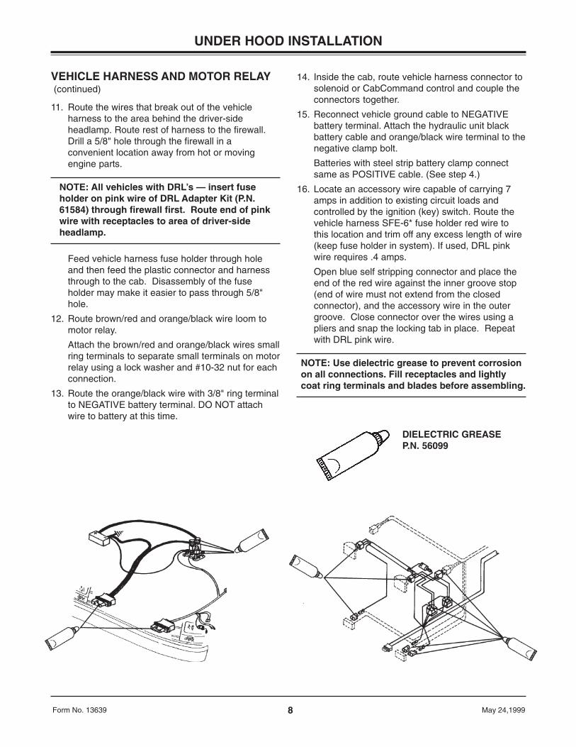
11. Route the wires that break out of the vehicleharness to the area behind the driver-sideheadlamp. Route rest of harness to the firewall.Drill a 5/8" hole through the firewall in aconvenient location away from hot or movingengine parts.
NOTE: All vehicles with DRL’s — insert fuseholder on pink wire of DRL Adapter Kit (P.N.61584) through firewall first. Route end of pinkwire with receptacles to area of driver-sideheadlamp.
Feed vehicle harness fuse holder through holeand then feed the plastic connector and harnessthrough to the cab. Disassembly of the fuseholder may make it easier to pass through 5/8"hole.
12. Route brown/red and orange/black wire loom tomotor relay.
Attach the brown/red and orange/black wires smallring terminals to separate small terminals on motorrelay using a lock washer and #10-32 nut for eachconnection.
13. Route the orange/black wire with 3/8" ring terminalto NEGATIVE battery terminal. DO NOT attachwire to battery at this time.
UNDER HOOD INSTALLATION
14. Inside the cab, route vehicle harness connector tosolenoid or CabCommand control and couple theconnectors together.
15. Reconnect vehicle ground cable to NEGATIVEbattery terminal. Attach the hydraulic unit blackbattery cable and orange/black wire terminal to thenegative clamp bolt.
Batteries with steel strip battery clamp connectsame as POSITIVE cable. (See step 4.)
16. Locate an accessory wire capable of carrying 7amps in addition to existing circuit loads andcontrolled by the ignition (key) switch. Route thevehicle harness SFE-6* fuse holder red wire tothis location and trim off any excess length of wire(keep fuse holder in system). If used, DRL pinkwire requires .4 amps.
Open blue self stripping connector and place theend of the red wire against the inner groove stop(end of wire must not extend from the closedconnector), and the accessory wire in the outergroove. Close connector over the wires using apliers and snap the locking tab in place. Repeatwith DRL pink wire.
NOTE: Use dielectric grease to prevent corrosionon all connections. Fill receptacles and lightlycoat ring terminals and blades before assembling.
DIELECTRIC GREASEP.N. 56099
9Form No. 13639 May 24,1999
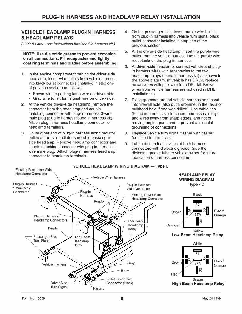
VEHICLE HEADLAMP PLUG-IN HARNESS& HEADLAMP RELAYS(1999 & Later - use instructions furnished in harness kit.)
NOTE: Use dielectric grease to prevent corrosionon all connections. Fill receptacles and lightlycoat ring terminals and blades before assembling.
1. In the engine compartment behind the driver-sideheadlamp, insert wire bullets from vehicle harnessinto black bullet connectors (installed in step oneof previous section) as follows:
• Brown wire to parking lamp wire on driver-side.• Gray wire to left turn signal wire on driver-side.
2. At the vehicle driver-side headlamp, remove theconnector from the headlamp and couplematching connector with plug-in harness 3-wiremale plug (plug-in harness found in harness kit).Attach plug-in harness headlamp connector toheadlamp terminals.
3. Route other end of plug-in harness along radiatorbulkhead or over radiator shroud to passenger-side headlamp. Remove headlamp connector andcouple matching connector with plug-in harness 1-wire male plug. Attach plug-in harness headlampconnector to headlamp terminals.
PLUG-IN HARNESS AND HEADLAMP RELAY INSTALLATION
4. On the passenger side, insert purple wire bulletfrom plug-in harness into vehicle turn signal blackbullet connector installed in step one of theprevious section.
5. At the driver-side headlamp, insert the purple wirebullet from the vehicle harness into the purple wirereceptacle on the plug-in harness.
6. At driver-side headlamp, connect vehicle and plug-in harness wires with receptacles to the twoheadlamp relays (found in harness kit) as shown inthe above diagram. (If vehicle has DRL’s, replacebrown wires with pink wire from DRL kit. Brownwires from vehicle harness are not used in DRLinstallations.)
7. Place grommet around vehicle harness and insertinto firewall hole (also put a grommet in the radiatorbulkhead hole if one was drilled). Use cable ties(found in harness kit) to secure harnesses, relaysand wires away from sharp edges, and hot ormoving engine parts and to prevent accidentalgrounding of connections.
8. Replace vehicle turn signal flasher with flasherfurnished in harness kit.
9. Lubricate terminal cavities of both harnessconnectors with dielectric grease. Give thedielectric grease tube to vehicle owner for futurelubrication of harness connectors.
VEHICLE HEADLAMP WIRING DIAGRAM — Type CExisting Passenger SideHeadlamp Connector
Plug-In Harness1-Wire MaleConnector
Plug-In Harness Headlamp Connectors
Purple
Passenger SideTurn Signal
Vehicle Harness
Parking
Bullet ReceptacleConnector (Black)
Brown
Driver SideTurn Signal
High BeamHeadlampRelay
Gray
Vehicle Wire Harness
Plug-In HarnessMale Connector
Purple
Plug-InHarness
Low BeamHeadlampRelay
Existing Driver SideHeadlamp Connector
Black
Brown Black/Orange
Yellow
Black/Orange
Low Beam Headlamp Relay
White
Brown
High Beam Headlamp RelayGreen
87
86 8530
87A
Orange
87
86 8530
87A
Red
HEADLAMP RELAYWIRING DIAGRAM
Type - C

10Form No. 13639 May 24,1999
FILLING HYDRAULIC UNIT
NOTE: Mount plow assembly to vehicle. (Seelabel on back of blade or Owner’s Manual formounting instructions.)
1. Push lift channel all the way down.
2. Remove fill plug and fluid level plug.
3. Fill unit through fill plug hole until fluid runs out offluid level plug hole.
4. Replace both plugs.
OPERATIONAL TESTS AND ADJUSTMENTS
USE
• Automatic transmission fluid (ATF) DEXRON® IIIto -10° F (-23° C)
• WESTERN® High Performance Fluidto -25° F (-32° C)
• Texaco 1537 Aircraft Hydraulic Oil fortemperatures below -25° F (-32° C)
5. Turn ignition (key) switch to the ON orACCESSORY position.
6. Turn the control ON/OFF switch to the ONposition.
7. Move control lever to angle left and angle rightseveral times to remove air from Hydra-Turn®rams.
FLUID CAPACITY
Solenoid ISARMATIC® Mark IIIa reservoir 1-3/4 quarts
Equipped with 10" Hydra-Turn® rams 2-3/8 quarts
DEXRON is a trademark of General Motors Corporation.
To prevent accidental movement of the blade,always turn the ON/OFF switch to OFFwhenever the snowplow is not in use. Thecontrol indicator light will turn off.
CAUTION
Remove fluid level plug slowly to allow anyresidual pressure in the reservoir to bleed off.
CAUTION
DO NOT raise blade as this may cause pumpcavitation.
CAUTION
8. Refill unit with fluid following the procedure insteps 1-4 of this section.
9. Move the control lever as indicated on label tocontrol the plow. Raise and lower plow severaltimes to remove air. Place control lever in floatposition. Push lift channel all the way down.Recheck fluid level according to steps 1-4 of thissection.
Fill Plug
Fluid Level Plug
11Form No. 13639 May 24,1999
OPERATIONAL TESTS AND ADJUSTMENTS
FINAL HYDRAULIC INSPECTION1. Make sure all fasteners and hydraulic and
electrical connections are tight.
2. Check ram packing nuts for oil leakage. If anyleakage is observed, tighten the packing nut 1/4turn after you feel the nut contact the packing.
NOTE: Do not over tighten packing nuts. Overtightening affects cylinder operation andshortens the life of the packing. A short periodof normal operation will allow chevron packingsto become saturated, and leakage will normallystop. A small amount of leakage is necessary toproperly lubricate the cylinder rod.
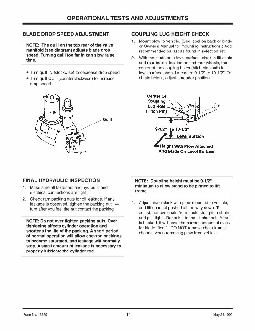
COUPLING LUG HEIGHT CHECK1. Mount plow to vehicle. (See label on back of blade
or Owner’s Manual for mounting instructions.) Addrecommended ballast as found in selection list.
2. With the blade on a level surface, slack in lift chainand rear ballast located behind rear wheels, thecenter of the coupling holes (hitch pin shaft) tolevel surface should measure 9-1/2” to 10-1/2”. Toobtain height, adjust spreader position.
BLADE DROP SPEED ADJUSTMENT
NOTE: The quill on the top rear of the valvemanifold (see diagram) adjusts blade dropspeed. Turning quill too far in can slow raisetime.
• Turn quill IN (clockwise) to decrease drop speed.• Turn quill OUT (counterclockwise) to increase
drop speed.
NOTE: Coupling height must be 9-1/2"minimum to allow stand to be pinned to liftframe.
4. Adjust chain slack with plow mounted to vehicle,and lift channel pushed all the way down. Toadjust, remove chain from hook, straighten chainand pull tight. Rehook it to the lift channel. After itis hooked, it will have the correct amount of slackfor blade “float”. DO NOT remove chain from liftchannel when removing plow from vehicle.
Quill
VEHICLE LIGHTING CHECK1. Check the operation of vehicle and plow lights with plow mounted to vehicle and both plow plugs connected.
Turn signals and parking lamps
Parking lamps ON Both vehicle and plow parking lamps should be on at the same time.Right turn signal ON Both vehicle and plow right turn signal lamps should flash at the same time.Left turn signal ON Both vehicle and plow left turn signal lamps should flash at the same time.
Headlamps
Move vehicle headlamp switch to the ON position. Connecting and disconnecting the 9-pin plow plugfrom the vehicle harness connector should switch between vehicle and plow headlamps as follows:
9-pin plow plug DISCONNECTED Vehicle headlamps should be on, plow headlamps off.9-pin plow plug CONNECTED Plow headlamps should be on, vehicle headlamps off.
Dimmer switch should dim whichever headlamps are operating. The high beam indicator on the dashshould light when either set of headlamps is on high beam.
Solenoid Control or CabCommand Control
9-pin vehicle harness revision 10 and later or9-pin vehicle harnesses – earlier revisions modified for CabCommand Control:
The control indicator light should light whenever the control ON/OFF switch and the ignition (key)switches are both turned ON. The plow plugs do not need to be connected to the vehicle harnessconnectors.
2. Connect plow plug to vehicle harness connector. Raise plow and aim plow headlamps according to SAE J599Lighting Inspection Code (See Service Bulletin SP 608) and any state or local regulations.
3. Check aim of vehicle headlamps with plow removed.
4. When plow is removed from the vehicle, install plug covers on vehicle harness connectors and insert the plowplugs into the boot on the hydraulic unit.
NOTE: After using the snowplow for 5-10hours, retorque all mount assembly fasteners.
12Form No. 13639 May 24,1999
OPERATIONAL TESTS AND ADJUSTMENTS
PLO
W L
IGH
TPA
SS
EN
GE
R-S
IDE
PLO
W L
IGH
TD
RIV
ER
-SID
E
Har
ness
Con
nect
or)
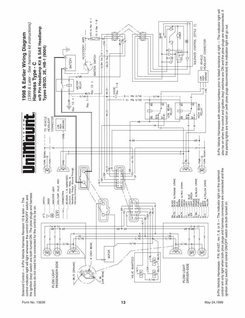
1998
& E
arlie
r W
irin
g D
iag
ram
(199
9 &
Lat
er -
See
har
ness
kit
inst
ruct
ions
)H
arn
ess
Typ
e -
Cw
/9 P
in H
ead
lam
p K
it &
SA
E H
ead
lam
pTy
pes
2B
/2D
, 2E
, HB
-1 (
9004
)
Sol
enoi
d C
ontr
ol —
9-P
in V
ehic
le H
arne
ss R
evis
ion
10 &
late
r —
The
cont
rol i
ndic
ator
ligh
t will
ligh
t whe
neve
r th
e co
ntro
l ON
/OF
F s
witc
h an
dth
e ig
nitio
n (k
ey)
switc
h ar
e bo
th tu
rned
ON
. The
plo
w p
lugs
and
har
ness
conn
ecto
rs d
o no
t nee
d to
be
conn
ecte
d fo
r th
e co
ntro
l to
be o
n.
13Form No. 13639 May 24,1999
9-P
in V
ehic
le H
arne
sses
- P
.N. 6
1437
, rev
7, 8
, or
9 —
The
indi
cato
r lig
ht o
n th
e so
leno
idco
ntro
l will
onl
y lig
ht w
hen
both
plo
w p
lugs
and
har
ness
con
nect
ors
are
conn
ecte
d an
d th
eig
nitio
n (k
ey)
switc
h an
d co
ntro
l ON
/OF
F s
witc
h ar
e bo
th tu
rned
on.
9-P
in V
ehic
le H
arne
sses
with
rev
isio
n nu
mbe
rs p
rior
to li
sted
rev
isio
ns a
t rig
ht —
The
indi
cato
r lig
ht w
illal
so b
e on
whe
n th
e co
ntro
l and
igni
tion
(key
) sw
itche
s ar
e O
N a
nd th
e pl
ow p
lugs
are
dis
conn
ecte
d. If
the
park
ing
light
s ar
e tu
rned
on
(with
plo
w p
lugs
dis
conn
ecte
d) th
e in
dica
tion
light
will
go
out.
1998
& E
arlie
r W
irin
g D
iag
ram
(199
9 &
Lat
er -
See
har
ness
kit
inst
ruct
ions
)H
arn
ess
Typ
e -
Cw
/9 P
in H
ead
lam
p K
it &
SA
E H
ead
lam
pTy
pes
2B
/2D
, 2E
, HB
-1 (
9004
)
Wit
h D
RL’
s
Sol
enoi
d C
ontr
ol —
9-P
in V
ehic
le H
arne
ss R
evis
ion
10 &
late
r —
The
cont
rol i
ndic
ator
ligh
t will
ligh
t whe
neve
r th
e co
ntro
l ON
/OF
F s
witc
h an
dth
e ig
nitio
n (k
ey)
switc
h ar
e bo
th tu
rned
ON
. The
plo
w p
lugs
and
har
ness
conn
ecto
rs d
o no
t nee
d to
be
conn
ecte
d fo
r th
e co
ntro
l to
be o
n.
14Form No. 13639 May 24,1999
9-P
in V
ehic
le H
arne
sses
- P
.N. 6
1437
, rev
7, 8
, or
9 —
The
indi
cato
r lig
ht o
n th
e so
leno
idco
ntro
l will
onl
y lig
ht w
hen
both
plo
w p
lugs
and
har
ness
con
nect
ors
are
conn
ecte
d an
d th
eig
nitio
n (k
ey)
switc
h an
d co
ntro
l ON
/OF
F s
witc
h ar
e bo
th tu
rned
on.
9-P
in V
ehic
le H
arne
sses
with
rev
isio
n nu
mbe
rs p
rior
to li
sted
rev
isio
ns a
t rig
ht —
The
indi
cato
r lig
ht w
illal
so b
e on
whe
n th
e co
ntro
l and
igni
tion
(key
) sw
itche
s ar
e O
N a
nd th
e pl
ow p
lugs
are
dis
conn
ecte
d. If
the
park
ing
light
s ar
e tu
rned
on
(with
plo
w p
lugs
dis
conn
ecte
d) th
e in
dica
tion
light
will
go
out.
PLO
W L
IGH
TPA
SS
EN
GE
R-S
IDE
PLO
W L
IGH
TD
RIV
ER
-SID
E
Har
ness
Con
nect
or)
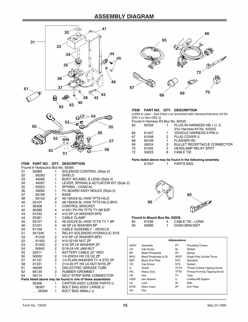
ITEM PART NO. QTY. DESCRIPTION(1999 & Later - See Parts List furnished with Harness/Harness Kit forDRL's or Non-DRL's)Found in Harness Kit Box No. 6252565 62526 1 PLUG-IN HARNESS HB-1 U -C
(For Harness Kit No. 62525)66 61437 1 VEHICLE HARNESS 9-PIN U67 61548 2 PLUG COVER U68 60109 1 FLASHER HD69 59224 3 BULLET RECEPTACLE CONNECTOR70 61535 2 HEADLAMP RELAY SPDT72 59223 8 CABLE TIE
Parts listed above may be found in the following assemblyITEM PART NO. QTY. DESCRIPTION 61547 1 PARTS BAGFound in Hydraulics Box No. 5636531 56369 1 SOLENOID CONTROL (Style 2)32 . 56283 1 SHIELD33 . 49286 1 BODY W/LABEL & LENS (Style 2)34 . 49287 1 LEVER, SPRING & ACTUATOR KIT (Style 2)35 . 55923 1 SPRING - CONICAL36 . 49283 1 PC BOARD ASSY MOLEX (Style 2)37 . 56199 1 BASE38 . 93153 2 #6-19X3/8 SL HXW TFTS HILO40 93154 2 #8-18X5/8 SL HXW TFTS HILO BPO41 56308 1 CONTROL BRACKET42 90388 4 #10X1 PH PN TFTS TY AB BZP43 91242 4 #10 SP LK WASHER BPO44 55381 1 CABLE CLAMP Found in Mount Box No. 6203545 93157 5 #8-32X3/8 SL HXW TCTS TY T BP 85 61536 4 CABLE TIE - LONG46 91231 4 #8 SP LK WASHER BP 90 56080 1 DASH BRACKET50 61169 1 CABLE ASSEMBLY - VEHICLE51 56134K 1 RELAY-SOLENOID HYDRAULIC SYS43 . 91242 2 #10 SP LK WASHER BPO52 . 91402 2 #10-32 HX NUT ZP53 . 91202 2 5/16 SP LK WASHER ZP54 . 92842 2 5/16-24 HX JAM NUT55 22511 1 BATTERY CABLE 22’’ RED56 90002 2 1/4-20X3/4 HX CS G2 ZP57 91101 2 1/4 PLAIN WASHER TY A STD ZP58 91331 1 21/4-20 PT HX LK NUT NYIS ZP61 56099 1 DIELECTRIC GREASE TUBE62 66130 2 RUBBER GROMMET63 59114 1 SELF STRIP WIRE CONNECTORParts listed above may be found in one of these assemblies
56368 1 CARTON ASSY LOOSE PARTS U. 56367 1 BOLT BAG ASSY LARGE U. . 56358 1 BOLT BAG SMALL U
ASSEMBLY DIAGRAM
15Form No. 13639 May 24,1999
Abbreviations
ASSY Assembly PT Prevailing TorqueCS Cab Screw SL SlottedBP Black Phosphate SP SpringBPO Black Phosphate & Oil SPDT Single Pole Double ThrowBZP Black Zink Plate STD StandardCS Cap Screw SYS SystemG Grade TCTS Thread Cutting Tapping ScrewHD Heavy Duty TFTS Thread Forming Tapping ScrewHX Hex TY TypeHXW Hex Washer U UniMount® SystemLK Lock W/ WithNYIS Nylon Insert ZP Zinc PlatePN Pan
61
31
32
33
34
35
36
37
41
4445
434238
406362
46
5053
54
5556
57
58
52
4351
72
65
67
68 69 70
66
90
85


Printed in USA May 24, 1999Form No. 13639
WESTERN PRODUCTSP.O. BOX 245038MILWAUKEE, WI 53224-9538
Western Products reserves the right under its Product Improvement Policy to change construction or design details and furnish equipmentwhen so altered without reference to illustrations or specifications used herein. Western Products and the vehicle manufacturer may requireand/or recommend optional equipment for snow removal. Western Products offers a limited warranty on the snowplows and accessories. Seeseparately printed page for this important information. The following are registered® and unregistered™ trademarks of Douglas Dynamics,L.L.C.: HYDRA-TURN®, ISARMATIC®, PRO-GUARD™, ROLL-ACTION ™, UNIMOUNT®, and WESTERN®.
A DIVISION OF DOUGLAS DYNAMICS, L.L.C.