Embed Size (px)
Citation preview

Basis for Identification of Disposal Options for Research and Development for Spent Nuclear Fuel and High-Level Waste
Prepared forU.S. Department of Energy
Used Fuel Disposition CampaignRob P. RechardBarry GoldsteinLarry H. Brush
Sandia National LaboratoriesJames A. Blink
Mark SuttonLawrence Livermore National Laboratory
Frank V. PerryLos Alamos National Laboratory
March 2011FCRD-USED-2011-000071
SAND2011-3781P
Basis for Identification of Disposal Options for Research and Development2 March 2011
DISCLAIMERThis information was prepared as an account of work sponsored by an agency of the U.S. Government. Neither the U.S. Government nor any agency thereof, nor any of their employees, makes any warranty, expressed or implied, or assumes any legal liability or responsibility for the accuracy, completeness, or usefulness, of any information, apparatus, product, or process disclosed, or represents that its use would not infringe privately owned rights. References herein to any specific commercial product, process, or service by trade name, trade mark, manufacturer, or otherwise, does not necessarily constitute or imply its endorsement, recommendation, or favoring by the U.S. Government or any agency thereof. The views and opinions of authors expressed herein do not necessarily state or reflect those of the U.S. Government or any agency thereof.
Sandia National Laboratories is a multi-program laboratory managed and operated by Sandia corporation, a wholly owned subsidiary of Lockheed Martin Corporation, for the U.S. Department of Energy’s National Nuclear security Administration under contract DE-AC04-94AL85000.

Executive SummaryMarch 2011 iii
EXECUTIVE SUMMARYThe mission of the Used Fuel Disposition (UFD) Campaign of the US Department of Energy (DOE) Office of Nuclear Energy is to identify alternatives and conduct research and technology development to enable storage, transportation, and disposal of used fuel from existing and future nuclear fuel cycles. As part of this mission UFD is developing analysis capability and general experimental data related to geologic disposal options. This report presents the rationale for focusing modeling and experimental efforts on mined, geologic repositories in three media (salt, clay/shale, and crystalline rocks), and the use of deep boreholes in crystalline rocks.
Preference for Geologic DisposalGeologic disposal has been the recommended option for permanent management of spent nuclear fuel (SNF) a and high-level waste (HLW) for 54 years. The National Academy of Sciences (NAS) reported that deep geologic disposal (in salt formations) was the most promising method to explore for disposing of HLW in 1957. NAS reaffirmed that position in 1966 and 1970. More recently in 2001, NAS concluded that after 40 years of study, “geologic disposal remains the only scientifically and technically credible long-term solution available to meet safety needs without reliance on active management” and there is overwhelming international consensus on geologic disposal as the preferred option.
Consideration of Salt, Clay/Shale, and Crystalline RocksIn the 1970s and early 1980s, the United States evaluated a number of geologic media. The Atomic Energy Commission (AEC), predecessor to DOE, gave disposal in salt priority based on an NAS recommendation in 1957. Sited in 1974, DOE developed the Waste Isolation Pilot Plant (WIPP) for disposal of defense transuranic waste in bedded salt in southern New Mexico. WIPP opened in 1999.
By 1974, AEC had also identified shale, volcanic tuff, and crystalline (igneous/metamorphic) rock as potential media in addition to salt. In the 1980 Environmental Impact Statement on Management and Disposal of Commercially Generated Radioactive Wastes (Generic EIS), DOE included repository concepts in salt, shale, crystalline rocks, and basalt. While searching for candidate sites for the first repository under the Nuclear Waste Policy Act of 1982, DOE selected three salt dome sites, four bedded salt sites, one basalt site, and the volcanic tuff site at Yucca Mountain. While searching for a site for the second repository in crystalline rocks in the mid 1980s, DOE also evaluated the feasibility of sedimentary rock and concluded clay/shale was still a favorable medium. In addition, alluvia in the United States and carbonate rocks in Canada have been considered for low- and intermediate-level waste.
By 1984, the United States had concluded that many types of geologic media were feasible for radioactive waste disposal, especially, if used with engineered barriers in addition to the natural barrier to create a robust disposal system. Hence, many types of media could be examined by the UFD Campaign. However, the UFD Campaign is not conducting in-situ experiments to develop properties of each geologic medium: rather, the UFD Campaign plans to the extent possible to use data available from underground research laboratories reported in the literature. Salt, clay/shale, and crystalline rocks are the most frequently considered geologic media in the international community. Crystalline repository concepts have been evaluated in Switzerland and Japan. Sweden and Finland have selected crystalline sites and are preparing licenses. Clay/shale disposal concepts have been evaluated in France, Belgium, and Switzerland. Finally, Germany continues to investigate disposal of heat-generating SNF and HLW in salt.
a In current usage, the term “used fuel” or “used nuclear fuel” is applied to fuel that has been irradiated in a reactor but for which no decision has been made about whether it will be reprocessed to recover usable radionuclides or disposed. This report discusses disposal options for used nuclear fuel for which presumably the decision has been made not to recover usable radionuclides. Hence, we use the broadly defined term spent nuclear fuel (SNF) as in the international community. This use of the term “spent nuclear fuel” is somewhat more restrictive that the definition in the current legal and regulatory framework for the United States, which uses the term spent nuclear fuel for all fuel withdrawn from a reactor.

Basis for Identification of Disposal Options for Research and Developmentiv March 2011
Furthermore, the UFD is not selecting a geologic medium for disposal, but rather is selecting a set of geologic media for further study that spans a suite of behavior characteristics that impose a broad range of potential conditions on the design of the repository, the engineered barrier, and the waste. Salt, clay/shale, and crystalline rocks represent a reasonable cross-section of behavior. Salt and clay/shale represent sedimentary rocks with different degrees of strength/cavity stability/mining experience, heat resistance/thermal conductivity, and radionuclide adsorptive behavior. Crystalline rocks (along with the US extensive experience with volcanic tuff) represent igneous rocks that differ from salt and clay/shale in deformation behavior/strength, importance of the waste package to the disposal system performance, and coexistence of economic resources and, thus, prevalence of boreholes and their associated hazards. Crystalline rocks are also the primary basement rock to consider for deep borehole disposal described below.
Preference for Mined Repositories Two thorough reviews of available options for management of HLW and SNF were conducted in 1974 and 1976 that considered surface storage in near-surface burial sites and disposal in deep mined repositories on the continent or islands, deep boreholes, seabed, geologic cavities coupled with rock melt, well injection, ice sheets, and space. By 1979, the Interagency Review Group for Nuclear Waste Management, formed the year before by President Carter with representatives from 14 federal agencies, concluded that mined, geologic repositories were a promising method for disposal of SNF and HLW.
A year later in the 1980 Generic EIS mentioned above, DOE concluded that mined geologic repositories were the best option for disposal because of favorable characteristics of ready retrievability during placement, continued retrievability after disposal (though increasingly difficult), status of technology, and conformance with international agreements when compared to liquid disposal in geologic cavities with rock melt and in injection wells and solid disposal in deep boreholes, in the sub-seabed, on islands, in continental ice sheets, and in space with or without transmutation of transuranic radioisotopes.
Borehole Disposal as AlternativeAlthough the 1980 Generic EIS selected mined repositories for geologic disposal, the DOE noted that deep borehole disposal was worthy of further consideration. The 1980 Generic EIS projected costs for deep borehole disposal to be about three times greater than for mined, geologic repositories. However, DOE conducted an engineering analysis of deep borehole emplacement in 1983 that found the concept feasible and costs similar to that of mined repositories in the future, provided technological advances in drilling methods continued. These technologic advances have indeed occurred and DOE investigated the concept in the 1990s for the disposal of surplus plutonium. Both the United Kingdom and the Swedish high-level waste programs continue to mention deep borehole disposal as the primary feasible alternative to mined geologic repositories in periodic reviews of alternatives. However, while it is the most common feasible alternative mentioned, it has not been demonstrated.
Other Disposal Options Not ConsideredThe 1980 Generic EIS also suggested further consideration of sub-seabed disposal and DOE studied the feasibility of this option through 1988, along with many other countries. It remains the most studied alternative to mined, geologic disposal. The seabed disposal concept consisted of emplacement of SNF and HLW by: (1) dropping streamlined penetrators containing waste packages into the unconsolidated seabed sediments; or (2) lowering waste packages into boreholes drilled into either unconsolidated or lithified seabed sediments. Although studies showed that radionuclide doses were often lower and subject to less uncertainty than repositories on land, participating countries decided to focus their efforts on land-based repositories and terminated the sub-seabed program in the late 1980s because seabed disposal had been prohibited under the United Nations Convention on Law of the Sea and the London Convention and Protocol.

Executive SummaryMarch 2011 v
No new information has been developed since the early 1980s to suggest that other options evaluated and screened from further consideration in the past should be re-evaluated. However, should these or other disposal concepts be identified that warrant further investigation, they will be evaluated by the UFD Campaign. Specifically, the UFD Campaign recognizes that analyses to date indicate that both sub-seabed disposal and the mined repository in volcanic tuff at Yucca Mountain have the potential to provide safe long-term isolation.

Basis for Identification of Disposal Options for Research and Developmentvi March 2011
ContentsMarch 2011 vii
CONTENTS
EXECUTIVE SUMMARY..........................................................................................................................iii
ACRONYMS................................................................................................................................................ ix
1. INTRODUCTION...............................................................................................................................11.1 Background...............................................................................................................................11.2 Approach...................................................................................................................................11.3 Report Organization..................................................................................................................2
2. DEVELOPMENT OF DISPOSAL OPTIONS....................................................................................32.1 Search for Permanent Storage...................................................................................................32.2 Analysis of Alternatives for HLW and SNF Isolation..............................................................32.3 Selection of Mined, Geologic Repositories..............................................................................7
3. POTENTIAL MEDIA FOR MINED GEOLOGIC DISPOSAL.......................................................113.1 Overview.................................................................................................................................113.2 Salt...........................................................................................................................................11
3.2.1 Brine Availability.......................................................................................................133.2.2 Temperature Effects...................................................................................................13
3.3 Clay/Shale...............................................................................................................................143.4 Carbonate Rocks and Chalk....................................................................................................16
3.4.1 Chalk..........................................................................................................................163.4.2 Carbonate Rocks........................................................................................................17
3.5 Crystalline Rocks....................................................................................................................183.6 Basalt.......................................................................................................................................213.7 Volcanic Tuff..........................................................................................................................22
4. ALTERNATIVE SETTINGS FOR GEOLOGIC DISPOSAL.........................................................244.1 Saturated Zone versus Unsaturated Zone................................................................................244.2 Continent Interior....................................................................................................................254.3 Coastal Areas..........................................................................................................................254.4 Islands.....................................................................................................................................26
5. ALTERNATIVES TO MINED DISPOSAL.....................................................................................285.1 Deep Boreholes in Igneous/Metamorphic Basement Rock....................................................285.2 Shallow Boreholes in Alluvium..............................................................................................305.3 Sub-seabed..............................................................................................................................325.4 Well Injection..........................................................................................................................345.5 Rock Melt................................................................................................................................36

Basis for Identification of Disposal Options for Research and Developmentviii March 2011
6. ALTERNATIVES TO GEOLOGIC DISPOSAL.............................................................................376.1 Engineered Mountain/Mausoleum..........................................................................................376.2 Ice-Sheet Disposal...................................................................................................................376.3 Space Disposal........................................................................................................................39
7. SUMMARY AND INSIGHT............................................................................................................417.1 Consideration of Mined, Geologic Disposal...........................................................................417.2 Deep Borehole Disposal as Most Feasible Alternative...........................................................417.3 Varied Attributes of Salt, Clay/Shale, and Crystalline Rocks................................................41
8. REFERENCES..................................................................................................................................46
FIGURESFigure 2-1. Nine sites for which DOE conducted environmental assessments (EAs) and from
which three site were nominated for characterization under NWPA........................................10
Figure 3-1. Salt deposits in the United States (Pierce and Rich 1962; Johnson and Gonzales 1978).........12
Figure 3-2. Clay/Shale provinces in the United States (Gonzales and Johnson 1984)................................16
Figure 3-3. Crystalline Rock Outcrops in the United States; the search for the second repository considered crystalline rocks in 17 states bordering the Great Lakes and Atlantic coast (i.e., MN, WI, MI, PA, NY, VT, ME, NH, MA, RI, CT, NJ, DE, MD, VA, NC, SC, GA); The 12 labeled sites in the 7 states of MN, WI, NH, ME, VA, NC, and GA were those proposed as potentially acceptable crystaline sties for the second repository (DOE 1986d) (Figure source: LANL).......................................................................................20
Figure 5-1. Sediment thickness in continental United States (MIT 2006)..................................................30
TABLESTable 2-1. Isolation Options Considered in the United States for HLW, SNF, and TRU Waste
(after Pittman 1974, Tables 1 and 9; ERDA 1976, Vol. 4, p. 1).................................................5
Table 6-1. Advantages and Disadvantages for Ice Sheet Disposal..............................................................38
Table 6-2. Advantages and Disadvantages for Space Disposal Concepts as Perceived in 1976 (ERDA 1976, Table 26.1)..........................................................................................................40
Table 7-1. Geologic Media and Experiments Considered in International Repository Programs and Underground Research Laboratories..................................................................................42
Table 7-2. Relative Attributes of Alternative Media for Geologic Disposal (BMWI 2008; Stenhouse et al. 2010, Figure 7-5; Hansen et al. 2010b, Table 1).............................................45
ContentsMarch 2011 ix
ACRONYMSAEC Atomic Energy CommissionAFR Away from ReactorANDRA National Radioactive Waste Management Agency (France)ANL Argonne National LaboratoryAPS American Physical SocietyATS Antarctic Treaty SystemBIA Bureau of Indian AffairsBNWL Battelle Northwest LaboratoryCFR Code of Federal RegulationsCSNF Commercial Spent Nuclear FuelDGR Deep Geologic RepositoryDOE Department of EnergyDRZ Disturbed Rock ZoneDSNF DOE-owned Spent Nuclear FuelEA Environmental AssessmentEIS Environmental Impact StatementEPA Environmental Protection AgencyERDA Energy Research and Development AdministrationGAO Government Accountability OfficeGCD Greater Confinement DisposalGME Great Meteor EastHLW High-Level WasteIAEA International Atomic Energy AgencyILW Intermediate Level WasteINL Idaho National LaboratoryIRG Interagency Review GroupLANL Los Alamos National LaboratoryLLNL Lawrence Livermore National LaboratoryLLW Low-Level WasteMPG Mid-plate, Mid-gyreMRS Monitored Retrievable StorageMTHM Metric Tons of Heavy MetalNAS National Academies of Science and EngineeringNWTS National Waste Terminal StorageNNWSI Nevada Nuclear Waste Storage InvestigationsNRC Nuclear Regulatory CommissionNTS Nevada Test SiteNWPA Nuclear Waste Policy ActNWPAA Nuclear Waste Policy Amendments ActOCRWM Office of Civilian Radioactive Waste ManagementOECD Organization of Economic Co-operation and Development OPG Ontario Power GenerationORNL Oak Ridge National LaboratoryOTA Office of Technology AssessmentPA Performance AssessmentPFS Private Fuel StoragePNNL Pacific Northwest National Laboratory

Basis for Identification of Disposal Options for Research and Developmentx March 2011
Pub. L. Public LawRATG Radiologic Assessment Task GroupRSSF Retrievable Surface Storage FacilityRWMC Radioactive Waste Management ComplexSATG SWG’s Site Assessment Task GroupSDP Sub-seabed Disposal ProgramSSM Swedish Radiation Safety AuthoritySNF Spent Nuclear FuelSNAP Southern Nares Abyssal PlainSWG Seabed Working GroupSZ Saturated ZoneTAD Technical Alternatives DocumentTRU TransuranicUFD Used Fuel DispositionURL Underground Research LaboratoryUSGS US Geological SurveyUN United NationsUZ Unsaturated ZoneWIPP Waste Isolation Pilot PlantYMP Yucca Mountain Project
IntroductionMarch 2011 1
USED FUEL DISPOSITION CAMPAIGNBASIS FOR IDENTIFICATION OF DISPOSAL
OPTIONS FOR RESEARCH AND DEVELOPMENT FOR SPENT NUCLEAR FUEL AND HIGH-LEVEL
WASTE1. INTRODUCTIONThe Used Fuel Disposition (UFD) Campaign is currently developing analysis and experimental capability for research and development on four primary disposal options for high-level radioactive waste (HLW) and spent nuclear fuel (SNF):b mined repositories in three geologic media (salt, clay/shale, and crystalline rocks), and the use of deep boreholes in crystalline rocks. This report discusses the basis for the decision to focus research and development on these four disposal options. The specific objectives of the report are to produce (a) a brief summary of alternatives for disposal of HLW and SNF that have been considered in the past and that form the current basis for choosing geologic disposal; and (b) a brief summary of the state of knowledge for disposal in the three potential natural systems (salt, clay/shale, and crystalline rocks), including any potential technical challenges that may be encountered if a particular geologic media is selected.
1.1 BackgroundThe Fuel Cycle Technology Program in the US Department of Energy (DOE) Office of Nuclear Energy is investigating alternative nuclear fuel cycles to provide a basis for future decisions on the nuclear fuel cycle in the United States. The safe management and disposition of radioactive waste is an important aspect of the nuclear fuel cycle. Thus, the Fuel Cycle Technology Program established the Used Fuel Disposition (UFD) Campaign to identify alternatives and conduct research to facilitate storage, transportation, and disposal of radioactive wastes generated by the current and alternative nuclear fuel cycles, and, thereby, develop a suite of options that will enable future decision-makers to make informed decisions about how best to manage used nuclear fuel. This mission also includes demonstration of technology necessary to allow commercial deployment for the sustainable management of used nuclear fuel that is safe, economic, secure, and widely acceptable to citizens of the United States.
1.2 ApproachRather than attempt an extensive analysis and discussion, this report summarizes a number of reviews of this subject that have been undertaken in the past 40 years (Pittman 1974; Schneider and Platt 1974; ERDA 1976; DOE 1980; OTA 1985; Lomenick 1996; NAS 2001; Apted 2010; Kozak 2010; Stenhouse et al. 2010; Apted et al. 2010).
1.3 Report OrganizationIn this report, the authors discuss Development of Disposal Options in Chapter 2; Potential Media for Mined Geologic Disposal (salt, clay/shale, carbonates, crystalline, basalt, and volcanic tuff) in Chapter 3; Alternative Settings for Geologic Disposal (saturated versus unsaturated zone, mid-continent, coastlines,
b In current usage, the term “used fuel” or “used nuclear fuel” is applied to fuel that has been irradiated in a reactor but for which no decision has been made about whether it will be reprocessed to recover usable radionuclides or disposed. This report discusses disposal options for used nuclear fuel for which presumably the decision has been made not to recover usable radionuclides. Hence, we use the broadly defined term spent nuclear fuel (SNF) as in the international community. This use of the term “spent nuclear fuel” is somewhat more restrictive that the definition in the current legal and regulatory framework for the United States. Specifically, the Nuclear Waste Policy Act of 1982 (NWPA) defines spent nuclear fuel as all “fuel that has been withdrawn from a nuclear reactor following irradiation, the constituent elements of which have not been separated by reprocessing”

Basis for Identification of Disposal Options for Research and Development2 March 2011
and islands) in Chapter 4; Alternatives to Mined Disposal (deep boreholes in igneous or metamorphic basement rock, shallow boreholes in alluvium, sub-seabed, well injection, and rock melt in Chapter 5; Alternatives to Geologic Disposal (an engineered mountain or mausoleum, ice-sheets, and space) in Chapter 6.

Development of Disposal OptionsMarch 2011 3
2. DEVELOPMENT OF DISPOSAL OPTIONS2.1 Search for Permanent StorageThe search for permanent storage for radioactive waste began in 1955 when the Atomic Energy Commission (AEC), formed in 1946, asked the National Academy of Sciences (NAS) to examine the disposal issue. In 1957, NAS reported that deep geologic disposal in salt formations was the most promising method to explore for disposing of HLW resulting from reprocessing of commercial SNF without aging the waste to lower the thermal load (NAS 1957). This opinion was reaffirmed in 1966 and 1970 (NAS 1966; 1970). With the technology currently available in the 1950 and 1960s, the AEC gave mined disposal in salt priority. However, AEC was slow in implementing a solution (Carter 1987; Walker 2009; Rechard 2000).
Then in May 1969, the Rocky Flat Plant, built by AEC in 1951, caught fire. Located only 26 km from Denver, the fire and subsequent cleanup attracted public attention. The press reported that radioactive waste from the cleanup was to be sent to Idaho. The public and many state officials learned that waste from Rocky Flats had routinely been sent to the Radioactive Waste Management Complex (RWMC), built in 1952 on the Idaho National Laboratory reservation near the Snake River and its associated aquifer. Because of its less than ideal location for permanent disposal, the AEC sought a more suitable site, and in June 1970, tentatively selected the abandoned Carey salt mine near Lyons, Kansas, the site of an underground research laboratory (URL) on heat dissipation in salt operated by Oak Ridge National Laboratory (ORNL) between 1963 and 1967 (OTA 1985, Ch. 4).
Although salt has many advantages, a disadvantage is the frequent coexistence of economic minerals and hydrocarbons. In 1971, a large number of boreholes for mineral exploration and some solution mining were discovered near the proposed mine. Because of local opposition, the AEC abandoned the Lyons Project (Walker 2009, p. 72-75) and announced to Congress in May 1972 plans for a Retrievable Surface Storage Facility (RSSF), in which waste could be stored “a minimum of 100 years” and enable the AEC to “keep open all options” and to “move slowly” to permanent disposition (Walker 2009, p. 80).
Nuclear opponents and the Environmental Protection Agency (EPA), through comments on the Environmental Impact Statement (EIS) for an RSSF issued in 1974, claimed an RSSF (at possibly Hanford reservation, Idaho RWMC, or Nevada Test Site) was de facto permanent disposal. In contrast, nuclear proponents thought an RSSF would take pressure off finding a disposal site (Carter 1987, p. 76; Walker 2009, p. 93-94). The criticism prompted the newly formed Energy Research and Development Administration (ERDA), the successor to the AEC, to abandon surface storage as a near term solution and emphasize the search for disposal sites with the help of the US Geological Survey (USGS).
2.2 Analysis of Alternatives for HLW and SNF IsolationAfter a 1.5 year study by Pacific Northwest National Laboratory (PNNL), AEC published its first technical analysis of methods for long-term management of HLW and SNF in May 1974 (Schneider and Platt 1974) along with a summary, High-Level Radioactive Waste Management Alternatives (Pittman 1974). The report described options, but did not present conclusions or policy recommendations. The generation of options was thorough in that no new categories of options have been identified since (although a few concepts were later added to some of the categories).c
In May 1976, ERDA had PNNL update and expand the Alternatives Report.d The update, Alternatives for Managing Wastes from Reactors and Post-Fission Operations in the LWR Fuel Cycle (referred to as the
c However, not all options ever proposed are included in Table 2-1. For example, disposal in volcanoes or magma chambers was proposed in the early 1970s (Schneider and Platt 1974) and the idea was again proposed recently (BRC 2011); however, the method to get close enough to reliably emplace the waste has not been proposed nor the fate after emplacement modeled.

Basis for Identification of Disposal Options for Research and Development4 March 2011
Technical Alternatives Document or TAD at the time) again did not evaluate and present conclusions or policy recommendations concerning the management options described (Table 2-1) (ERDA 1976).
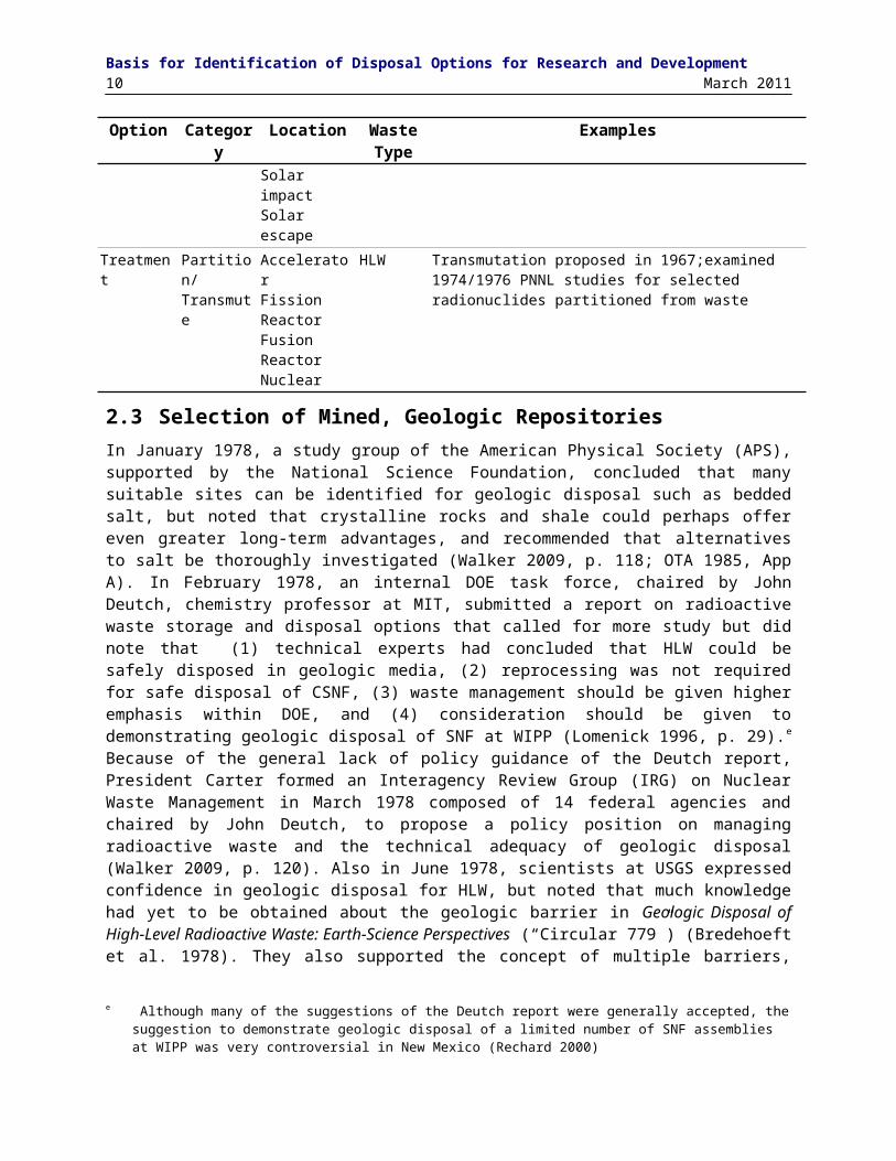
The major categories and some of the options are briefly discussed in the following chapters. Waste types other than those that exist today are not considered here, although there is good reason to conclude that disposal concepts that will safely isolate existing wastes will perform well for a broad range of waste forms. Treatment options of the waste, specifically, partitioning/transmutation (through capture by the nucleus of neutrons produced by, for example, an accelerator or a fission reactor) is not the topic of the report, but is mentioned in Table 2-1 since partitioning/transmutation of transuranic radioisotopes to faster decaying radioisotopes was considered in conjunction with storage and disposal options from the 1970s and again in the 1990s
In the waste isolation options listed in Table 2-1, both the first and second PNNL reports categorized mined, geologic repositories as a storage option (ERDA 1976, Vol. 4, p. 1) as did those reporting in the scientific literature (e.g., Winograd 1974). Furthermore a “repository” was described as a “terminal storage” facility. Closure after backfilling and sealing the terminal storage facility was described as permanent storage. Storage referred to waste isolation concepts with the planned ability to readily retrieve in the near-term, especially during a pilot phase, but with retrievability still possible later after closure. Disposal referred to waste isolation concepts with no initial provision or intention for retrieval. The subtle distinction and classification of mined, geologic terminal storage facilities as readily retrievable storage followed by permanent storage would disappear in the United States with the definitions of disposal and repository in the Nuclear Waste Policy Act of 1982 (NWPA) (Pub. L 97-425):
The term “disposal” means the emplacement in a repository of high-level radioactive waste, spent nuclear fuel, or other highly radioactive material with no foreseeable intent of recovery, whether or not such emplacement permits the recovery of such waste.
The term “repository” means any system licensed by the Commission that is intended to be used for, or may be used for, the permanent deep geologic disposal of high-level radioactive waste and spent nuclear fuel, whether or not such system is designed to permit the recovery, for a limited period, during initial operation…
The remainder of this text will use this statutory definition of disposal; however, several remnants of this distinction remained through the 1980s; for example, the ERDA (and DOE) program conducting the search for disposal options for commercial fuel was titled the National Waste Terminal Storage (NWTS) Program and the project at the Nevada Test Site (NTS), set up by DOE in 1977 and continued into the 1980s, was titled the Nevada Nuclear Waste Storage Investigations (NNWSI) project. Furthermore, the Assurance Requirements (40 CFR 191.14(f)) in the EPA 1985 health standard for HLW, SNF, and TRU waste (40 CFR 191) stated that “disposal systems shall be selected so that removal of most of the waste is not precluded for a reasonable period of time after disposal.” In promulgating the rule (EPA 1985, preamble) the EPA noted that “any current concept for a mined geologic repository meets this requirement without any additional procedures or design features…this provision should not have any effect upon plans for mined geologic repositories. Rather, it is intended to call into question any other disposal concept that might not be so reversible—because the agency believes that future generations should have options to correct any mistakes that this generation might unintentionally make.”
d The update had a number of contributors. For example Sandia National Laboratories (SNL) led the evaluation of geologic disposal concepts (as defined in Table 2-1) and Oak Ridge National Laboratory (ORNL) led the evaluation of geologic storage options (as defined in Table 2-1) with contributions from Los Alamos National Laboratory (LANL).

Development of Disposal OptionsMarch 2011 5
Table 2-1. Isolation Options Considered in the United States for HLW, SNF, and TRU Waste (after Pittman 1974, Tables 1 and 9; ERDA 1976, Vol. 4, p. 1).
Option Category Location WasteType
Examples
Storage Disposition (provisionfor retrieval)
Surface of land
Distributed HLW Hanford, WA: single-shelled tanks in 1944; double-shelled tanks in 1971Savannah River: tanks in 1957Idaho National Laboratory (INL): stainless steel tanks in 1953; solidified as calcine in stainless steel tanks in 1963
SNF Wet pools for commercial SNF at 1st reactor in PA in 1957Air- or water-cooled vaults suggested in 1973; dry storage vaults/casks examined in 1974/1976 studies coordinated by Pacific Northwest National Laboratory (PNNL)Dry storage casks demonstrated in 1986 at Surry reactor in VA
Centralized TRU RWMC (Radioactive Waste Management Complex) on INL reservation storage TRU on surface after ordered by AEC in 1971
SNF/HLW RSSF (Retrievable Surface Storage Facility; AEC proposal in 1974 for air-cooled vaults, water- cooled vaults or single canister casks; EPA and others called it de facto permanent disposal) AFR (Away-from-Reactor) storage proposed by President Carter in 1977)MRS (Monitored Retrievable Storage) proposed in NWPA 1982; DOE selects TN in 1986; Congress nullified, proposed Negotiator in NNWPA 1987; expired without success)PFS (Private Fuel Storage) proposal on Goshute tribe land in UT; licensed by NRC in 2005; Bureau of Indian Affairs (BIA) nullifies lease in 2006Desert pyramid proposed 1971
Geologicon land
Near-surfaceburial (trench, crater, or shallowborehole)
TRU RWMC (constructed on Snake River alluvium in ID in 1953)HLW/SNF NAS examines option in 1957; USGS proposes unsaturated
zone (30-40 m from surface) of southwest desert in 1974TRU USGS proposes alluvium of Great Basin or at craters at NTS in
1981GCD (Greater Confinement Disposal) facility in alluvium on NTS from 1983 to 1989)
All Desert pyramid proposed in 1971; artificial mountain over mined pit informally discussed in ~1985 and 2001; no conceptual designs or costs have been made
Deep All NAS examines option in 1957; AEC studies Carey Mine between 1963 and 1967; option considered in 1974/1976 PNNL studies and selected in 1980 EIS
All AEC examined liquid HLW disposal (1961-1962) and solid HLW disposal (1963-1968) at Carey mine in bedded salt near Lyons, KA; proposed as repository in 1971 initially for TRU waste and debris from Rocky Flats Plant fire
TRU/HLW
WIPP in bedded salt in southeast NM, sited in 1974 and opened for only TRU in 1999

Basis for Identification of Disposal Options for Research and Development6 March 2011
Option Category Location WasteType
Examples
Storage Disposition (provision for retrieval)
Geologic on land
Deep SNF/HLW
Draft EAs for 9 sites for 1st repository in 19844 bedded salt sites (Deaf Smith, TX; Swisher, TX; Davis Canyon, UT; Lavendar Canyon, UT)3 domal salt (Vacherie, LA; Richton, MS; Cypress Creek, MS)1 basalt site (Hanford, WA)1 tuff sites(NTS, NV proposed 1976)Sedimentary rocks evaluated; shale selected as option in 198412 sites in 7 states for 2nd repository in crystalline rocks selected in 1986 (MI, WI, ME, NH, VA, NC, GA), but deferred indefinitely
Island Option proposed in 1974/1976 PNNL studies and 1980 EISDisposal (no provision for retrieval)
Geologic on land
Trenches Liquid HLW
ORNL implemented in 1943NAS examined option in 1957Savannah River implemented in 1953
Well Injection after hydrofrac
Liquid HLW
NAS examined option in 1957Proposed in 1974/1976 PNNL studies (co-located with reprocessing) and examined in 1980 EIS; Option places HLW in impermeable formation after hydrofracture (crystalline, salt, shale rocks examined); ORNL implemented in 1959 in shale for LLW and TRU; option explored at L
Well-Injection in permeable media
Option is placement in permeable formation bounded by impermeable media; suitable areas in US identified in 1959 by AEC; option implemented for liquid ILW by Russians in sandstone, limestone, and dolomite formation in 1966-1973
Cavity Rock Melt
Liquid HLW
First proposed in 1971 by LLNL and evaluated in 1974/1976 PNNL studies; option is cavity (formed by mining, solution mining, or nuclear explosive) filled with liquid HLW which eventually melts rock (co-located with reprocessing)
SNF/HLW
Cavity filled with solid waste; water circulated to cool until ready to melt rock
DeepBorehole
SNF/HLW
Mentioned in 1974/1976 PNNL studies; drilling to 2 km and placement of canisters considered feasible in early and mid 1970s (but 10 km depth considered infeasible); coupling with rock melt proposed by SNL in 1974; 1980 Generic EIS considered worthy of further examination; option examined for excess Pu in 1990s
Seabed geologic
Stable basin SNF/HLW
Proposed in 1969 and evaluated in 1974/1976 PNNL studies; delivery by penetrator into unconsolidated clay or drilling into clay, lithified sediment, or basalt crust; 1980 Generic EIS considered worthy of further examination; extensive international evaluation between 1974 and 1988
Subduction zones/ trenches
First proposed in 1971 and mentioned in 1974/1976 PNNL studies; later dismissed because repository could be disrupted before adequate movement into trench
Rapid Sediment zones
Areas near river deltas proposed in 1972 and mentioned in 1974/1976 PNNL studies; later dismissed because repository could be disrupted before adequate coverage
Ice sheets Surface building
All Ice sheets first proposed in 1958 and evaluated in 1974/1976 PNNL studies; this option is where waste canisters placed in

Development of Disposal OptionsMarch 2011 7
Option Category Location WasteType
Examples
surface building on pedestals for air cooling; building would eventually melt into ice sheet
Free fall burial Option where waste placed in borehole and canister allowed to melt to bedrock
Anchored burial
Option where waste placed in borehole but with surface anchor so that canister would not melt to bedrock
Space Earth orbitMoon/planet impactSolar orbitSolar impactSolar escape
Partitioned nuclides
Proposed in 1974/1976 PNNL studies for selected radionuclides partitioned from the waste
Treatment Partition/ Transmute
AcceleratorFission ReactorFusion ReactorNuclear
HLW Transmutation proposed in 1967;examined 1974/1976 PNNL studies for selected radionuclides partitioned from waste
2.3 Selection of Mined, Geologic RepositoriesIn January 1978, a study group of the American Physical Society (APS), supported by the National Science Foundation, concluded that many suitable sites can be identified for geologic disposal such as bedded salt, but noted that crystalline rocks and shale could perhaps offer even greater long-term advantages, and recommended that alternatives to salt be thoroughly investigated (Walker 2009, p. 118; OTA 1985, App A). In February 1978, an internal DOE task force, chaired by John Deutch, chemistry professor at MIT, submitted a report on radioactive waste storage and disposal options that called for more study but did note that (1) technical experts had concluded that HLW could be safely disposed in geologic media, (2) reprocessing was not required for safe disposal of CSNF, (3) waste management should be given higher emphasis within DOE, and (4) consideration should be given to demonstrating geologic disposal of SNF at WIPP (Lomenick 1996, p. 29).e Because of the general lack of policy guidance of the Deutch report, President Carter formed an Interagency Review Group (IRG) on Nuclear Waste Management in March 1978 composed of 14 federal agencies and chaired by John Deutch, to propose a policy position on managing radioactive waste and the technical adequacy of geologic disposal (Walker 2009, p. 120). Also in June 1978, scientists at USGS expressed confidence in geologic disposal for HLW, but noted that much knowledge had yet to be obtained about the geologic barrier in Geologic Disposal of High-Level Radioactive Waste: Earth-Science Perspectives (“Circular 779”) (Bredehoeft et al. 1978). They also supported the concept of multiple barriers, which expanded the range of feasible geologic media for storage and disposal. The numerous evaluations for radioactive waste isolation had not identified options more feasible than geologic disposal and mined repositories in particular, and, between 1976 and 1980, the technical community and DOE continued to favor mined, geologic disposal.
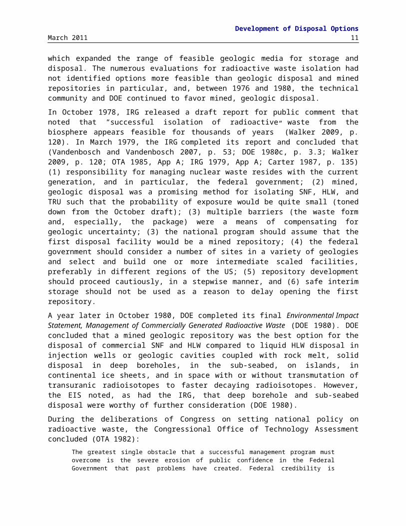
In October 1978, IRG released a draft report for public comment that noted that “successful isolation of radioactive waste from the biosphere appears feasible for thousands of years” (Walker 2009, p. 120). In March 1979, the IRG completed its report and concluded that (Vandenbosch and Vandenbosch 2007, p. 53; DOE 1980c, p. 3.3; Walker 2009, p. 120; OTA 1985, App A; IRG 1979, App A; Carter 1987, p. 135) (1) responsibility for managing nuclear waste resides with the current generation, and in particular, the federal government; (2) mined, geologic disposal was a promising method for isolating SNF, HLW, and TRU such that the probability of exposure would be quite small (toned down from the October draft); (3)
e Although many of the suggestions of the Deutch report were generally accepted, the suggestion to demonstrate geologic disposal of a limited number of SNF assemblies at WIPP was very controversial in New Mexico (Rechard 2000)

Basis for Identification of Disposal Options for Research and Development8 March 2011
multiple barriers (the waste form and, especially, the package) were a means of compensating for geologic uncertainty; (3) the national program should assume that the first disposal facility would be a mined repository; (4) the federal government should consider a number of sites in a variety of geologies and select and build one or more intermediate scaled facilities, preferably in different regions of the US; (5) repository development should proceed cautiously, in a stepwise manner, and (6) safe interim storage should not be used as a reason to delay opening the first repository.
A year later in October 1980, DOE completed its final Environmental Impact Statement, Management of Commercially Generated Radioactive Waste (DOE 1980). DOE concluded that a mined geologic repository was the best option for the disposal of commercial SNF and HLW compared to liquid HLW disposal in injection wells or geologic cavities coupled with rock melt, solid disposal in deep boreholes, in the sub-seabed, on islands, in continental ice sheets, and in space with or without transmutation of transuranic radioisotopes to faster decaying radioisotopes. However, the EIS noted, as had the IRG, that deep borehole and sub-seabed disposal were worthy of further consideration (DOE 1980).
During the deliberations of Congress on setting national policy on radioactive waste, the Congressional Office of Technology Assessment concluded (OTA 1982):
The greatest single obstacle that a successful management program must overcome is the severe erosion of public confidence in the Federal Government that past problems have created. Federal credibility is questioned on three main grounds: 1) whether the Federal Government will stick to any waste policy through changes of administration; 2) whether it has the institutional capacity to carry out a technically complex and politically sensitive program over a period of decades; and 3) whether it can be trusted to respond adequately to the concerns of States and others who will be affected by the waste management program.
After nearly four years of work, the Congress passed the Nuclear Waste Policy Act of 1982 (NWPA) (Pub. L 97-425; Carter 1987, Ch 6). The NWPA endorsed the policy, voiced earlier in studies such as the IRG, that the current generation should bear the costs of developing a permanent disposal option and selected the mined geologic disposal option. NWPA also addressed each of the three issues of a credible waste management program by replacing the administrative process that was attempted in the 1970s with a congressionally mandated process.
Concerning the first issue, the NWPA required the federal government to identify two repository sites for Commercial Spent Nuclear Fuel (CSNF) and operate one of them. The first repository was statutorily limited to a mass of 70,000 MTHM (metric tons heavy metal initially placed in reactor), until a second repository was in operation.
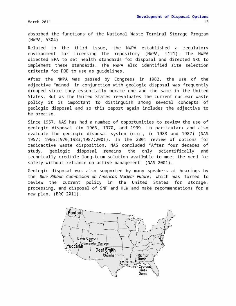
Also concerning the first issue, the NWPA established steps to meet the goals and an aggressive timetable for opening the first repository. Because of the aggressive schedule, DOE conducted site selection while developing the guidelines, and the nine sites that were previously under consideration using administrative procedures were identified for screening for the first repository under NWPA in February 1983 (Figure 2-1): three salt dome sites—one in Louisiana and two in Mississippi, four bedded salt sites—two in Texas and two in Utah, one basalt site at Hanford, Washington, and the volcanic tuff site at Yucca Mountain ( DOE 1986a). By December 1984, DOE had issued draft environmental assessments (EAs) of all nine sites meeting the schedule set up by NWPA. The draft EAs suggested five candidate sites for nomination for further study (three salt sites: Davis Canyon, Utah; Deaf Smith, Texas; Richton dome, Mississippi; one basalt site: Hanford, Washington; and one tuff site: Yucca Mountain). DOE also presented a ranking analysis in the draft EAs that suggested Yucca Mountain, Deaf Smith, and Hanford were the top three of the five candidate sites (Joy et al. 1985). f
Related to the second issue, the NWPA assigned responsibility for the waste management functions to the single-purpose Office of Civilian Radioactive Waste Management (OCRWM), a new office within DOE that absorbed the functions of the National Waste Terminal Storage Program (NWPA, §304)
f The alternative of starting with a new national site screening process had been explicitly considered and rejected during the debates on NWPA (OTA 1985).

Development of Disposal OptionsMarch 2011 9
Related to the third issue, the NWPA established a regulatory environment for licensing the repository (NWPA, §121). The NWPA directed EPA to set health standards for disposal and directed NRC to implement these standards. The NWPA also identified site selection criteria for DOE to use as guidelines.
After the NWPA was passed by Congress in 1982, the use of the adjective “mined” in conjunction with geologic disposal was frequently dropped since they essentially became one and the same in the United States. But as the United States reevaluates the current nuclear waste policy it is important to distinguish among several concepts of geologic disposal and so this report again includes the adjective to be precise.
Since 1957, NAS has had a number of opportunities to review the use of geologic disposal (in 1966, 1970, and 1999, in particular) and also evaluate the geologic disposal system (e.g., in 1983 and 1987) (NAS 1957; 1966;1970;1983;1987;2001). In the 2001 review of options for radioactive waste disposition, NAS concluded “After four decades of study, geologic disposal remains the only scientifically and technically credible long-term solution available to meet the need for safety without reliance on active management” (NAS 2001).
Geologic disposal was also supported by many speakers at hearings by the Blue Ribbon Commission on America’s Nuclear Future, which was formed to review the current policy in the United States for storage, processing, and disposal of SNF and HLW and make recommendations for a new plan. (BRC 2011).
Figure 2-1. Nine sites for which DOE conducted environmental assessments (EAs) and from which three site were nominated for characterization under NWPA.

Basis for Identification of Disposal Options for Research and Development10 March 2011
3. POTENTIAL MEDIA FOR MINED GEOLOGIC DISPOSAL 3.1 OverviewUse of salt formations for SNF, HLW, and TRU waste disposal was widely embraced during the 1960s and early 1970s. Yet by 1974, additional geologic media were thought to possess favorable properties for mined, geologic waste disposal, and ERDA investigated shale, carbonate rocks, crystalline rocks, basalt, and tuff as part of the Geologic Disposal Evaluation Program (Lomenick 1996, App. B). Hence by 1980, the Generic EIS considered crystalline rocks, shale, and basalt in addition to salt deposits (bedded and dome) when demonstrating the behavior and virtues of mined, geologic disposal (DOE 1980). USGS had suggested the use of volcanic tuff at the Nevada Test Site (NTS) in 1978, and tuff was seriously considered by 1984 for the environmental assessments (EA) required under NWPA. In addition to these five media, the following also discusses carbonates since Canada has plans for disposal of low- and intermediate-level waste (LLW and ILW) in this medium.
3.2 SaltDisposal in salt was suggested as the most promising method for the near future 54 years ago by the NAS (NAS 1957). Shortly thereafter, AEC asked USGS to describe locations and characteristics of salt formations in the US. A draft of the report was available in 1958, the final published in 1962 (Pierce and Rich 1962; Lomenick 1996, p. 7). Use of a bedded salt formation for radioactive waste disposal has been successfully demonstrated by 11 years of successful operations for disposal of TRU waste at the Waste Isolation Pilot Plant (WIPP) near Carlsbad, NM. In the international community, Germany disposed LLW and ILW at Morsleben and considered HLW disposal in the salt dome at Gorleben until October 2000 and had a URL at the Asse salt mine. Further work at Gorleben has been on hold while the high level waste management program reevaluates guiding policies and examines the feasibility of clay/shale and possibly crystalline rocks (Stenhouse et al. 2010, Ch 7).
A salt repository could potentially contain the waste, with no releases to the environment, for as long as the region is geologically stable and no human intrusion occurs. Positive attributes for salt disposal include:
Salt has high thermal conductivity to readily transport heat from package Salt is visco-plastic and thus readily deforms and flows into mined rooms and entombs the waste
in the first 100 yr Salt fractures formed during excavation heal as the room creeps closed Salt has very low permeability and porosity Salt is easily mined as demonstrated by 1000s of years of mining and recent operations at WIPP
ensure that a solid foundation exists for repository design and construction Salt creates a self-supporting cavity for about a decade under ambient temperature Salt deposits are often in stable tectonic regions Salt deposits exist in many locations with wide geographic distribution in the US
Disposal of radioactive waste in salt remains a feasible concept because of the many salt formations, including bedded and domal salt formations in the conterminous United States (Figure 3-1) (Johnson and Gonzales 1978). Bedded formations of salt (sodium chloride) are found in layers interspersed with materials such as anhydrite, shale, dolomite, and other salts such as potassium chloride. These formations can range across enormous land areas. Bedded salt formations are often between 200 to 600 m thick, but in some cases they can have thicknesses of up to 1000 m in the United States. Salt domes form from salt beds when the density of the salt is less than that of overburden sediment. Under such conditions, the salt has a tendency to move slowly upward toward the surface. As the buoyant salt moves upward, it deforms plastically into mushroom-shaped diapirs and other cylindrical and anticlinal shapes. The top of some

Potential Media for Mined Geologic DisposalMarch 2011 11
domal salt can be near surface, while the base may extend to a great depth. The diameter of a typical salt dome is on the order of 5 km (Hansen and Leigh 2011).
Figure 3-2. Salt deposits in the United States (Pierce and Rich 1962; Johnson and Gonzales 1978)
Salt has several unfavorable characteristics that include high dissolution and low ability to adsorb radionuclides except on clay mineral interspersed within the salt. As is discussed with other media, the significance of unfavorable characteristics depends on the particular site chosen. Although salt is easily dissolved, the very presence of a salt formation over geologic time demonstrates lack of water flow through the salt. Provided no features of the site can be found to disrupt current conditions, the existence of the salt formation provides evidence that it will remain as it has for the foreseeable geologic future. Also, without a pathway and gradient to move radionuclides, the lack of an intrinsic absorptive characteristic can be unimportant.
United States regulations required an evaluation of a human intrusion, which by-passed the salt host rock. Hence, the human intrusion scenario forced an evaluation of characteristics of nearby formations. In the case of WIPP, these features included a brine aquifer above the repository. The brine was unfit for human consumption without treatment and the dolomite aquifer was a dual porosity medium with adequate physical retardation to delay releases. Hence, the surrounding formations had features that compensated for the low adsorptive behavior of the salt.
Two factors of salt can influence the operating and initial post-closure period of the repository that will involve continued research for SNF disposal: brine availability and salt creep. Although the permeability and porosity are very low, a stable salt repository is likely in the saturated zone. Also, operation of the repository may have to accommodate rapid salt creep at elevated temperatures even though the plastic salt creep is a significant advantage for long-term waste isolation.

Basis for Identification of Disposal Options for Research and Development12 March 2011
3.2.1 Brine AvailabilityBrine availability is an important factor in the overall evolution of a salt repository. The estimated performance of WIPP was highly dependent upon the presence or absence of brine. Corrosion of the waste package and degradation of the waste, both of which can generate gas, requires the presence of brine. In the absence of brine, a salt repository would be extremely robust. Brine availability is largely determined by the properties of the disturbed rock zone (DRZ). The three important properties of the DRZ that contribute to the amount and rate of brine flow into the repository are extent (thickness), porosity, and permeability.
Beauheim and Roberts (2002) performed an evaluation of Salado Formation hydrology and hydraulic properties. They conclude that
On the time scale of the operational period of WIPP (decades), the far field lacks the capacity to fill all of the newly created porosity in and around the repository, much less pressurize it to near lithostatic pressure. After WIPP is closed, far-field flow toward the repository will continue, but the overall “healing” of the formation around the repository (closure) and compaction of the crushed-salt backfill will act to reduce both the hydraulic gradient and the porosity present near the waste. Thus, the amount of brine that ever comes into contact with waste will be controlled by the relative rates at which brine flow and repository closure occur.
Based on modeling and experiments over the 10 yr operating life, the DRZ appears to be of limited extent (Hansen 2003). Supporting evidence include laboratory testing, theoretical developments, modeling, and observation. For example, a limited DRZ is supported by lack of copious amounts of brine observed in the rooms. Because moist areas were evident soon after mining, a brine sampling and evaluation program (BSEP) investigated the origin, hydraulic characteristics, extent and chemical composition of brine in the Salado Formation. The BSEP program noted, however, that after 11 years of study, brine was remarkably hard to find in the WIPP excavations (Deal et al. 1995).
3.2.2 Temperature EffectsEvolution of the disposal rooms will involve a thermal pulse from the heat-generating SNF. Most of the experience with heat-generating nuclear waste in the United States is from Project Salt Vault conducted in the 1960s (Bradshaw and McClain 1971) and the underground research laboratory experiments at WIPP conducted in the 1980s (Matalucci 1988).
Temperature effects on salt deformation are dramatic, as salt deformation is dominated by plastic behavior at elevated temperatures. Temperature has an exponential influence on the creep rate of intact salt specimens owing to thermally-activated deformation mechanisms: the elevated temperature in a SNF repository will enhance deformation upon placement of the heat-generating waste in the rooms.
Increased temperature results in enhanced creep of the host salt, but could cause thermally-induced fracturing and thermally driven flow of brine. Thus, temperature limits may need to be established such that the performance of the waste forms or the disposal canisters/waste packages are more predictable during the operational phase of the repository. Examples of thermal limits considered in past designs for repositories in salt include
The design basis for the WIPP requires that the thermal loading for RH transuranic waste does not exceed 10 kilowatt (kW) per acre (DOE 2004)
The Gesellschaft für Anlagen und Reaktorsicherheit (GRS) assumes that a 200 C limit at the container/salt interface would be established by regulation for a repository located in a salt formation in Germany (NEA 2006)
The Environmental Assessment for the disposal of spent nuclear fuel and high level nuclear waste at the Deaf Smith County Texas site (DOE 1986c) used a maximum allowable repository temperature of 250 C with a maximum waste package surface temperature of 230 C
Potential Media for Mined Geologic DisposalMarch 2011 13
3.3 Clay/ShaleIn November 1976, ERDA notified 36 governors that it would be looking for repository sites in their state. By this time, interest in other media had increased because, as already noted in Section 2, a general consensus developed in the mid to late 1970s on the desirability of multiple barriers, which, in turn, could compensate for a few unfavorable characteristics of a geologic medium. Along with their endorsement of geologic disposal in 1978, the American Physical Society (APS) concluded that in addition to bedded salt, crystalline rocks and shale might offer other advantages (OTA 1985, App A). Similarly, the Interagency Review Group (IRG) for Nuclear Waste Management, concurred with the suitability of salt as a host formation, but the IRG further recommended that the federal government consider a number of sites in a variety of geologic media in 1979.
ORNL had proposed thick clay or shale sequences for geologic repositories in 1972 (Gere and Jacobs 1972). Hence, during the 1970s and early 1980s, the AEC Geologic Disposal Evaluation Program, then the ERDA Nuclear Waste Terminal Storage (NWTS) Program examined the feasibility of clay/shale. In 1974, USGS investigated characteristics of shale and the Pierre Shale in North and South Dakota and Indiana University investigated Mid-Continent shale in Illinois. The Green River oil shale formations were also examined. A study of liquefied petroleum gas storage caverns revealed that over half were in shale (Cobb Engineering 1976), and a study of dry mines in the country (usually in carbonate formations) revealed that single most important factor was the presence of impermeable shale above the carbonate formation (Lomenick 1996, p. 80). Sandia National Laboratories (SNL) conducted two small-scale field heater tests related to repository applications for NWTS: (1) Eleana argillite on the Nevada Test Site (NTS) (Lappin et al. 1981); and (2) Conasauga shale near Oak Ridge (Krumhansl 1983), where ORNL had injected liquid LLW and TRU waste since 1959. These latter shale repository studies culminated with a workshop in 1985 (ORNL 1986).
The sites for the first repository under the administrative and the NWPA program did not include shale site. However, in the 1987 Mission Plan Amendment released before passage of the Nuclear Waste Policy Act Amendments (NWPAA), the DOE described an alternative program for proceeding with a second repository that started the second repository program over again with a national site screening process that would expand the types of geologic media and number of geographical areas considered. In order to increase the diversity of rock types under consideration by the geologic repository program, the DOE had initiated the Sedimentary Rock Program (SERP) in 1984. The objective of this program was to evaluate five sedimentary rocks (clay/shale, sandstone, carbonates, anhydrite, and chalk) to determine the potential for locating a geologic repository site in one of these rock types. In the ORNL draft report, clay/shale was found to be equal to, or better than, the other four rock types (Lomenick 1996; DOE 2008b).
Since the mid 1980s, European repository programs have continued to advance clay/shale repository concepts and provide tangible assurance and confidence that a repository can be built and operated to isolate HLW. In the international community, Belgium, France, and Switzerland are considering HLW repositories in clay/shale. Also, as part of its reevaluation, Germany is examining the feasibility of clay/shale at international URLs.
In this report, the term clay/shale is used to represent a spectrum of material from unconsolidated clay to highly consolidated argillite. The term clay usually refers to a non-indurated (mechanically soft) material having more than two-thirds clay-sized grains. Clay materials have the characteristics of showing plastic behavior at sufficiently high water content and harden upon drying (Guggenheim et al. 1995). Various terms are used to describe clays that have undergone some degree of diagenesis. Exposure of clay to increased pressure and temperature than experienced in the depositional environment leads to induration, or hardening. USGS defines claystone, mudstone, and shale as indurated rock having more than two-thirds clay-sized grains, with shale having laminations not found in claystones and mudstones (Houseworth 2011). Argillite is derived from either mudstone or claystone that has undergone a somewhat higher degree of induration than shale but is less clearly laminated than shale. Argillaceous
Basis for Identification of Disposal Options for Research and Development14 March 2011
rock is another term, slightly different from argillite, used to describe rock formed predominantly from clay-sized or clay minerals. Because high clay content is desirable to ensure low permeability and plasticity, argillaceous rock is also frequently used to describe this general group of rocks suitable for radioactive waste disposal.
Positive attributes for clay/shale include (Hansen et al. 2010a)
Clay/shale is plastic if clay content is high Clay/shale fractures self heal if clay content is high Clay/shale has very low permeability (10-17 to 10-23 m2) and often forms barriers to fluid flow in
sedimentary sequences Clay/shale readily adsorbs radionuclides Clay/shale deposits are often in stable tectonic regions Clay/shale deposits exist in many locations with wide geographic distribution in the US
Although construction, ventilation, and the thermal pulse will dehydrate the clay, the influence should be confined to within a few meters of the repository that can be reasonably characterized. Within a few centuries after waste emplacement, overburden pressures will seal fractures, resaturate the dehydrated zones, and provide a repository setting that limits radionuclide movement to diffusive transport. Thus, the maximum extent of radionuclide transport due to diffusion is on the order of tens to hundreds of meters, or less, in 106 yr and thus it may be possible to achieve total containment, with no releases to the environment in undisturbed scenarios (Hansen et al. 2010a).
Hansen et al (2010a) conclude with some observations for future work that are applicable to the UFD Campaign:
Technical studies of shale for repository purposes were engaged in the U.S. for a number of years, ending in the 1980s with implementation of the NWPA and passage of the NWPA Amendments. These historical studies provide useful support for the current report. The actual experimental work was limited, however, and has been surpassed by new experimental and modeling approaches that have been developed by the scientific community in the intervening 30 years. These new methods can provide far greater precision in site characterization, repository design, and performance assessment. The new tools should be deployed in conjunction with an underground test facility, and with strengthened technical exchanges with other nations already committed to developing repositories in clay/shale media…
The THMC [thermal hydrologic mechanical and chemical] responses of clay/shale media are more complex than for salt, tuff, or granite. This complexity can be mitigated to some extent by maintaining sub-boiling (less than 100°C) temperatures, but research needs include measurement of material properties for multi-physics representation of repository performance. Validation of multiphysics predictions depends on full-scale thermal-hydrologic-mechanical field testing in representative clay/shale media. As confidence in multi-physics models increases, they could be used in a science-based approach to evaluate design alternatives, and to predict the outcomes from pilot-scale field tests. International experience has shown that full-scale demonstration of disposal (“proof-of-principle”) is needed to build confidence in the disposal concept of operations, and predictions of long-term performance.
As with salt, clay/shale provinces are broadly distributed in the US (Figure 3-2)

Potential Media for Mined Geologic DisposalMarch 2011 15
Figure 3-3. Clay/Shale provinces in the United States (Gonzales and Johnson 1984).
3.4 Carbonate Rocks and ChalkTo increase the diversity of rock types under consideration by the geologic repository program, DOE initiated in 1984 a project which had as its objective the evaluation of the common types of sedimentary rocks (other than salt) to determine the likelihood of their being suitable as hosts for a repository. The study was conducted by ORNL. A draft report of that study concluded that clay/shale ranked highest, followed in decreasing order of likely suitability by sandstone, carbonate rocks, anhydrite, and chalk; however, the report noted that suitable sites probably could be found in each rock type (Lomenick 1996). Because Canada is investigating a low and intermediate level waste (LLW and ILW) repository in carbonate rock, we review characteristics of carbonates and related chalk formations. As surmised from the following discussion, carbonates and chalk do not have uniquely favorable characteristics that cannot be found in the suite of salt, clay/shale, and crystalline rocks media, except for one. The carbonates (e.g., calcium carbonate or calcite in the chalk and limestone) provide an excellent naturally occurring, abundant buffering capacity that can maintain near neutral pH conditions as the waste and packages degrade.
3.4.1 ChalkAn early review of thick chalk formations in the United States included the extensive Cretaceous Selma Chalk found along the Gulf Coast Plain from south-central Alabama to northeast Mississippi; the mid-continent Niobrara Formation in eastern Nebraska, central and western Kansas, and eastern Colorado; the Austin Chalk of east-central to northeast Texas; and other, less-developed Cretaceous and Tertiary chalks (Gonzales 1975; 1977).
Favorable characteristics as a waste disposal medium were found to be (Gonzales 1975) (1) low permeability (2) reasonably thick and widespread (3) occurrence in regions of very low seismicity and only slight structural deformation (4) extremely fine-grained and thus some self-sealing plastic behavior, and (5) the absence of water within subsurface excavations. The buffering capacity of the calcite is also another favorable characteristic.
Basis for Identification of Disposal Options for Research and Development16 March 2011
Chalk's negative characteristics were found to be (1) localized, small-scale fractures and faults (2) low compressive strength and spalling when excavated; (3) frequent association with montmorillonitic clay, which has a tendency to lose or gain water and change in volume; (4) proximity to freshwater aquifers and association with petroleum reservoirs and thus penetrations by numerous petroleum wells, and in some areas, deep water wells (Lomenick 1996).
3.4.2 Carbonate RocksCarbonate rocks, which for this discussion consists of marbles and limestones, have favorable buffering capability, physical adsorption and chemical fixation characteristics, and moderate resistance to thermal damage, which supports the potential suitability of carbonate rock as the host rock for a HLW/SNF repository.
The effect of thermal damage on the physical properties has been investigated on five carbonate rocks: two marbles and three limestones, mainly composed of calcite but with different grain sizes, porosities, structural and textural characteristics. Physical properties (bulk density, effective porosity and ultrasonic velocity) were measured to assess the degree of thermal damage. Cubic samples prepared from these rocks were gradually heated to a 100, 200, 300, 400 and 500 oC, and gradually cooled down to room temperature without causing thermal shock. Most of the sample destruction occurred within 24 hr of heating. Cracking due to thermal effect was not so significant in carbonate rocks when the temperature was less than 150 oC. Following this threshold temperature, considerable destruction started in all rocks. In general terms, marbles were found to be more prone to microcracking than both low and highly porous limestones up to 300 oC heating temperature, but limestones were significantly damaged between 300 and 500 oC (Yavuz et al. 2010).
The porosity of the thermally damaged marbles and less porous limestones generally increased with the increase in temperature; however, compaction of the rock structure up to 150 oC occurred. Compaction of rock structure led to a slight decrease in porosity, which is a favorable characteristic for nuclear waste isolation (Yavuz et al. 2010). Hence, carbonate rocks, especially limestone, may be able to maintain its structural integrity and be a viable media for nuclear waste disposal if temperatures are maintained below 150 oC.
The occurrence of radionuclides in fracture fillings at the Palmottu analogue site, around Precambrian uranium ore deposits, provides evidence of uranium sequestration over very large time intervals in calcite (Pomiès et al. 2004). It appears that both physical adsorption and chemical fixation play a role in the immobilization of uranium in the calcite-coated fractures (Suksi et al. 1991). The fillings were composed of calcite with varying amounts of clays and pyrite (Blomquist et al. 1995, p.25). Most of the uranium (~60-70% of the total) is bound in calcite phases in the fracture coatings. Specifically, a significant quantity of uranium (6-23%) could be removed before calcite dissolution, which suggests fixation by physical adsorption and/or ion exchange. The remainder of the 60 to 70% was released by dissolution in ammonium acetate buffer, which suggests chemical fixation (Blomquist et al. 1995, p.54-55).
The Ontario Power Generation company of Canada has proposed to build a 680-m deep geologic repository (DGR) in limestone for ~160,000 m3 of low and intermediate level waste (LLW and ILW). The operational and refurbishment wastes from OPG’s nuclear reactors will be emplaced in a steel and concrete waste containers and overpacks. The total activity at closure is about 16,000 TBq. Key radionuclides in terms of total activity include 3H, 14C and 63Ni at short times, and 94Nb and 93Zr at long times (Little et al. 2009).
The projected advantages of the DGR site location are
The location of the DGR at a depth of 680 m underground, absence of economically viable natural resources, and no drinking water below 100 m provide excellent isolation from the biosphere
The host rock provides multiple thick low-permeability sedimentary rock barriers

Potential Media for Mined Geologic DisposalMarch 2011 17
Mass transport is diffusion-dominated at the repository horizon. Hydrogeochemical conditions limit contaminant mobility at the repository horizon Resaturation of the repository with groundwater will be very slow The large volume of limestone host rock (calcium carbonate) provides a significant chemical
buffering capacity, which tend to maintain near neutral chemical conditions within the repository The Normal Evolution Scenario of a performance assessment done for the DGR shows that, after closure, the repository will quickly become anaerobic. The repository will start to fill slowly with water seeping in from the surrounding rocks. The slow anaerobic degradation of the waste packages will result in the generation of gases. The full resaturation of the repository is not observed in models for more than 1 million years, due to the low permeability of the host rock and gas generation in the repository (Little et al. 2009).
Calculations show that less than 0.001% of the initial activity disposed in the repository is released into the geosphere and shaft and, of this, less than 0.1% eventually reaches the surface environment. Gases are contained within the repository and geosphere, with only small amounts of gases (dissolved in groundwater) reaching the surface. The estimated maximum repository pressure for the base case is 8.5 MPa, about 1 MPa above the initial steady-state pressure at the repository level, and well below the lithostatic pressure of about 17 MPa at the repository level (Little et al. 2009).
3.5 Crystalline RocksThe NAS first mentioned the possibility of disposal in dry mines in crystalline rocks in 1957 and repeated the possibility in 1966 (NAS 1957; NAS 1966; Winograd 1974). The United States considered deep metamorphic rocks (gneiss, schist, and quartzite) for disposal beneath the Savannah River Plant, SC in the early 1960s (Lomenick 1996, p. 81; Christl 1964).
In the 1970s, the USGS and DOE investigated the suitability of crystalline rocks as part of DOE’s Crystalline Rock Program because of their occurrence throughout much of the country (Smedes 1980; Brookings 1985). In 1978, DOE funded the construction of an URL at a depth of 420 m in the Climax Stock granite at the NTS. Testing involved emplacement of 11 CSNF canisters and 6 simulated canisters into boreholes placed in the floor of a drift for the purpose of assessing waste handling and retrievability operations, as well as assessing the technical suitability of crystalline rocks as a host rock for SNF (Patrick 1986).
For the second repository required by NWPA, DOE chose to pursue a crystalline rock site in the eastern United States. By 1986, more than 200 crystalline rock bodies in 17 states had been screened prior to selecting 12 rock bodies in the 7 states of Michigan, Wisconsin, Maine, New Hampshire, Virginia, North Carolina, and Georgia for further consideration (DOE 1986d) (Figure 3-3). However, DOE indefinitely deferred the search for a second repository site in 1986 (Carter 1987; Vandenbosch and Vadenbosch 2007).
In the international community, crystalline repository concepts have been evaluated in Canada (at Lac du Bonnet URL), Switzerland (major URL at Grimsel test tunnel), and Japan. Sweden and Finland have selected crystalline rocks sites and are preparing licenses. Sweden characterized two sites in crystalline rocks and in June 2009 and chose the Forsmark site as their repository site, based partly on a lower fracture density. The implementer, the Swedish Nuclear Fuel and Waste Management Co. (SKB), plans to submit a license application for construction in March 2011 (SSM 2011; EPRI 2010c). Finland is expected to submit a license application at the end of 2012 (EPRI 2010c).

Basis for Identification of Disposal Options for Research and Development18 March 2011
Positive attributes of crystalline (igneous/ metamorphic) rocks include the following (Heiken et al. 1996; NRC 1978; Smedes 1980; Améglio and Vigneresse 1999; Migon 2006):
Crystalline rocks have high strength and thus drifts are usually self-supporting in unfractured areas Crystalline rocks are resistant to mineral alteration from heat and the thermal conductivity is
moderate Crystalline rocks can have low permeability in unfractured areas and, thus, low water content and
often fairly dry mines Crystalline rocks are moderately homogeneous Crystalline rocks can have moderate adsorption of radionuclides Crystalline rocks provide a stable chemical environment for the waste and engineered barriers Crystalline rocks are unlikely to intercept unforeseen mineral resources Crystalline rocks can be found in stable tectonic regions Crystalline rock lack active faults in the continental shields and cratons Crystalline rocks are often massive with great thickness and lateral extent, with geophysical
methods providing reliable information on extent Crystalline rocks exist within 1 km of the surface exist in many areas of the US.
Published data on crystalline rocks is abundant in the United States; yet, site-specific information as a potential host rock is limited except in countries with URLs (NRC 1978; Smedes 1980; Heiken et al. 1996; Young and Collins 2001; ANDRA 2005; Johannesson et al. 2007; IAEA 2001). Although crystalline rocks tend to be sparsely-to-moderately fractured in between widely spaced zones of intense fracturing (SKB 2000), the discontinuities (faults, joints, fractures) are the primary controls on groundwater flow in low permeability crystalline rocks. The spatial density, size distribution, orientation patterns, and transmissivity of fractures are key attributes that need to be determined during site characterization. Geophysical methods have proven to be effective at locating fracture zones in granite (Cosma et al. 2001). Statistical characterization of fracture patterns through an intensive site characterization campaign, though difficult, has been demonstrated to be feasible (SKB 2008). Hence, one aspect of crystalline rocks that may be a topic of research and development by the UFD Campaign will be how to effectively use site characterization data on discontinuities and build models from this data.
Based on available published data and results from international URLs and international repository programs in crystalline rocks, crystalline rocks have been shown to provide a viable option for long-term nuclear waste disposition. Total system performance simulations documented by Swedish, Finnish, and Canadian agencies indicate doses to the biosphere over one million years that are within acceptable limits (SKB 2006d; Posiva 2010; Garisto et al. 2009). Much credit is taken for the performance of the waste package copper outer barriers. Other factors include low waste form degradation rates and the low solubility of most radionuclides under reducing conditions. Although glacial periods are predicted to enhance groundwater circulation at depth, calculations indicate that these effects are minor and short-lived and will therefore have limited effects on the EBS (e.g., Posiva 2010, Section 9.5).
The United States has many occurrences of crystalline rocks. According to published information compiled from outcrops, cuttings and drill cores, and geophysical explorations, about 90% of the conterminous United States is underlain by crystalline basement rocks. Much of this basement rock is covered by less than one km of sedimentary and volcanic rocks and ~ 10% of the US has crystalline rocks exposed at the surface (Figure 3-3) (Reed and Harrison 1993; Sims 1993, Van Schmus et al. 1993; Bush et al. 1976).

Potential Media for Mined Geologic DisposalMarch 2011 19
Figure 3-4. Crystalline Rock Outcrops in the United States; the search for the second repository considered crystalline rocks in 17 states bordering the Great Lakes and Atlantic coast (i.e., MN, WI, MI, PA, NY, VT, ME, NH, MA, RI, CT, NJ, DE, MD, VA, NC, SC, GA); The 12 labeled sites in the 7 states of MN, WI, NH, ME, VA, NC, and GA were those proposed as potentially acceptable crystaline sties for the second repository (DOE 1986d) (Figure source: LANL).
Crystalline rocks are found in several distinct geologic and tectonic settings within the conterminous U.S. (Smedes 1980; Reed and Harrison 1993; Sims 1993; Van Schmus et al. 1993):
1. New England and Upstate New York: Large areas of crystalline rocks are exposed across much of upstate New York, New Hampshire, and Vermont that are assigned to Phanerozoic crystalline rock terrains. The Adirondacks crystalline rocks represent a shield area.
2. Appalachians: Tectonically exposed Precambrian rocks form considerable topography. They are generally deformed.
3. Central Midwest: Tectonically exposed crystalline basement rocks that form the Wichita Mountains magmatic province of southern Oklahoma and the Llano uplift of central Texas.
4. Northern Midwest: Large areas of Wisconsin and Minnesota contain Precambrian crystalline rocks that are within the southern Canadian Shield.
5. Rocky Mountains: The mountain ranges running from the Canadian border to central New Mexico contain extensive crystalline-rock terrains.
6. Basin and Range: The region contains Phanerozoic crystalline-rock terrains that are highly faulted and covered by Tertiary volcanic rocks. Information on tectonic stability of the region is readily available from previous studies related to the NTS and Yucca Mountain Project.
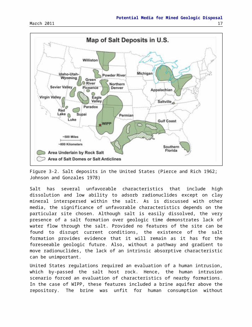
Basis for Identification of Disposal Options for Research and Development20 March 2011
7. Pacific Coast and the Sierra Nevada. One of the largest regions of the US with outcrops of crystalline basement rock runs from the Mexican border through California and the length of the Sierra Nevada. There are also blocks along the coast south of San Francisco and across the California-Oregon border. The Cordilleran batholiths are marginal to Precambrian basement.
3.6 BasaltBasalt is a fine-grained, hard crystalline rock resulting from the eruption or intrusion and cooling of magma from the Earth’s mantle. Studies of the Hanford basalts of the Columbia River Plateau as a potential repository site began in the late 1970s, primarily because the Hanford Site was a DOE reservation that engaged in nuclear operations. The newly formed DOE, successor of ERDA, added previous land use as a criterion for identifying sites in 1977. Also, in 1979 the Comptroller General of the United States in 1979 proposed that (CG 1979)
It [DOE] should give first consideration to determining if any of the existing, highly contaminated reservation are acceptable because
- using them would avoid contaminating any more areas of the United States with radioactivity;- disposal of the Department of Energy generated waste would be simplified;- the sites are already federally owned, are in remote locations, and are in some cases so badly contaminated
that they can never be returned to general use; and- public and political acceptance of these locations for waste disposal is likely to be higher than in other parts
of the country. With the exception for the Hanford Site in the U.S., basalt has not been considered as a potential host rock for HLW in the international literature (e.g., Chapman 2006). Basalt bodies with sufficient thickness to host a repository are relatively uncommon in continental settings, with the exception of major flood basalt provinces or intrusive complexes where individual unit thicknesses can exceed 100 m. A dozen or more major flood basalt provinces are present on the Earth’s continents, with the Deccan Traps of India, the Siberian traps, and the Columbia River basalts of Pacific Northwest being the better known examples. In the conterminous U.S., the few basalt occurrences with sufficient thickness to potentially host a repository include the flood basalts of the Columbia River Plateau (where the Hanford Site is located), the Keweenawan lavas of the Lake Superior region, and certain intrusive rocks such as the Palisades Sill of New Jersey and New York.
The Hanford Site lies within the Pasco Basin, a topographic depression filled with basalt flows to a thickness of greater than 4000 m. Several basalt flows at depths greater than 600 m are sufficiently thick to potentially host a repository (DOE 1986b). The basalt at Hanford offered several potential advantages as a repository host rock, which are similar to crystalline rocks and include (DOE 1986b)
Basalt has moderate strength and thus drifts are usually self-supporting in unfractured areas Basalt is resistant to mineral alteration from heat and the thermal conductivity is moderate Basalt provides a stable reducing chemical environment for the waste and engineered barriers Basalt flows are massive with great thickness Basalts are not typically deposited concurrently with economically valuable resources
However, basalt is commonly highly fractured and basalt flow sequences typically include major horizontal discontinuities at flow boundaries that can provide paths for groundwater flow (i.e., basalt is not typically homogeneous). Besides the simple assessment of a basalt site completed for the 1984 draft and 1986 final EA, a demonstration performance assessment was completed for NRC by SNL in 1989 (Bonano et al. 1989), to understand the impact these features might have on water movement through basalt (Brookins 1985), but detailed performance assessments were never completed.

Potential Media for Mined Geologic DisposalMarch 2011 21
The Hanford Site was recommended by the Secretary of Energy to the President under the provisions of the original NWPA in 1986 as one of the three candidate sites for site characterization (DOE 1986a). Although not ranked as one of the top three sites by the DOE’s multi-attribute utility analysis (DOE 1986b), the Hanford site met post-closure performance criteria using a simplified analysis, and was recommended in part to preserve the diversity of geologic media (basalt, salt, tuff) recommended for site characterization in NWPA (DOE 1986a). Site characterization studies for basalt at Hanford ended with passage of the NWPAA, which designated Yucca Mountain as the sole site for further site characterization.
3.7 Volcanic Tuff In 1976, USGS suggested that ERDA emplace nuclear waste at the NTS because of its (a) closed hydrologic groundwater basin, (b) long groundwater flow paths to potential outflow points, (c) many different types of rock at NTS suitable for waste isolation, (d) remoteness, (e) past nuclear testing, (f) desert (~150 mm/yr precipitation), and (g) thick, unsaturated zone (Winograd 1974; Winograd 1981; DOE 1986a; Carter 1987, p 131).
In 1978, the cabinet level DOE (newly formed from ERDA) decided that a repository could be built in the southwestern portion of NTS and not disrupt weapons tests. Site investigations began at the Calico Hills area to look at crystalline rocks and argillite; Wahmonie to look at crystalline rocks, and Yucca Mountain to look at volcanic tuff. The investigations found only small, highly fractured crystalline rocks masses and structurally complex argillite; however, borehole UE-25a#1, cored to ~2,500 ft, confirmed the presence of thick volcanic tuff deposits near Yucca Mountain.
In 1979, USGS recommended that investigations focus on welded tuff at Yucca Mountain. Investigations to find suitable argillite and crystalline rocks sites in other parts of NTS were stopped; however, work at Climax granite continued to determine the general suitability of granite as an URL, as previously mentioned (Patrick 1986). By 1982, the Site Evaluation Working Group, organized in 1980, had formally screened 15 locations in southwestern portion of NTS and reported that Yucca Mountain remained the preferred site for a repository (Sinnock and Fernandez 1984). Similar to basalt, volcanic tuff has not been considered as a potential host rock for HLW in the international literature (e.g., Chapman 2006).
Because tuff was not considered previously by NAS, DOE asked NAS to consider the suitability of tuff for waste disposal in 1978. The intrinsic advantages of tuff are fairly similar to crystalline rocks and basalt (Rechard 1995, Ch 5; DOE 1986a):
Volcanic tuff has high strength and thus drifts are usually self-supporting in unfractured areas Volcanic tuff is resistant to mineral alteration from heat (except zeolites) and the thermal
conductivity is moderate Volcanic zeolitic tuff has moderate to high adsorption of radionuclides Volcanic tuff can have great thickness Volcanic tuff is not typically deposited concurrently with economically valuable resources
Yucca Mountain consists of successive layers of fine-grained volcanic rocks called tuffs, millions of years old, underlain by older carbonate rocks. These tuffs were formed when hot volcanic gas and ash erupted and flowed quickly over the landscape or settled from the atmosphere. In instances when the temperature was high enough, the ash was compressed and fused to produce a welded tuff. Nonwelded tuffs, which typically occur between welded layers, were consolidated at lower temperatures, and, thus, are less dense, and have a higher porosity.
Because of the manner of deposition, the stratigraphy of tuffs is difficult to characterize generally, except that they are far from homogeneous in the vertical direction. Most tuff deposits involve repeated
Basis for Identification of Disposal Options for Research and Development22 March 2011
deposition. Within any one layer, variations will exist. For example, an ash flow may consist of a highly welded tuff sandwiched between nonwelded upper and lower portions that cooled rapidly. Furthermore, each layer has a different cooling history and may be deposited upon an eroded and reworked bedded layer.
The proposed repository horizon is located in the unsaturated zone a minimum of ~210 m (690 ft) above the water table in the present-day climate (DOE 2008a, Section 2.0). The behavior and performance of the Yucca Mountain repository is intimately connected to the placement of the repository in the unsaturated zone and is discussed in the next section.

Alternative Settings for Geologic DisposalMarch 2011 23
4. ALTERNATIVE SETTINGS FOR GEOLOGIC DISPOSAL This section discusses four alternative locations for geologic disposal on the earth surface. The first section covers the important distinction between disposal in the saturated zone and disposal in the unsaturated zone. Then locations in remote islands, in coastline areas, and in mid-continental areas are discussed.
4.1 Saturated Zone versus Unsaturated ZoneThe United States was unique in proposing a SNF/HLW repository in the unsaturated zone. In 1982, USGS had identified several advantages for using the unsaturated zone (UZ) at Yucca Mountain, and on their recommendation, DOE moved the repository to the UZ (DOE 1986a, p. 2-44).
From the perspective of the chemical aspects of long term waste isolation, a saturated site with reducing chemistry conditions is likely to be advantageous over a site with oxidizing conditions because many of the long-lived radionuclides have very low solubility and mobility in reducing conditions. In addition, if intact spent fuel is to be directly disposed, the UO2 is more stable in reducing environments than in oxidizing environments. In an oxidizing environment (and assuming that barriers that protect the fuel have been breached), UO2 will oxidize to U3O8. When UO2 converts to U3O8, the volume increases and the fuel pellets fracture so that it does not retain fission products or actinides nearly as well as UO 2 does (Apted 2010, Section 3.3; Whipple 2010)
However, the trade-off between a saturated site and an unsaturated one is not as straightforward as simply looking at the effect of the local environment on UO2. Some radionuclides, such as 129I, can be highly mobile and soluble in either environment. The approach taken to construct a robust disposal system to restrict their release and migration in the Yucca Mountain design depended on engineered barriers – a highly corrosion-resistant waste canister and a titanium drip shield to divert infiltrating water around the waste. Yet, corrosion-resistant engineering features are also necessary at a saturated site in crystalline rocks to construct a robust disposal system. For example, both the Finnish and Swedish repository designs include copper waste canisters surrounded by low-permeability clay (Whipple 2010).
Advantages of the UZ include (Winograd 1974; Roseboom 1983): (1) most waste would not contact much water in the UZ since openings typically block flow, due to capillarity; (2) source and direction of water flow are known; (3) water flux could be estimated through direct observation (4) passive ventilation of repository is possible to keep waste cool; (5) backfilling of drifts unnecessary; (6) sealing of shafts is unnecessary; (7) many exploratory holes could be drilled without compromising repository; (8) saturated zone adds additional travel time as a barrier; and (9) long straightforward retrieval period because the repository does not flood.
To elaborate on the first point, in the unsaturated zone, seepage into the emplacement drifts is only a few percent of the percolation flux because capillary forces limit the movement of water into the drift openings. Water is retained in the small pores and tight fractures of the low-porosity welded tuff, and a substantial fraction of the flow moves around the drift opening and drains through the rock pillars between the drifts (DOE 2008a, Section 2.3.3.2). In addition for a period of time, the decay heat of the emplaced waste is great enough to heat the rock near the emplacement drifts. As long as the temperature is above the boiling point of water at the drift wall, liquid water will be vaporized. This thermal effect further limits seepage into the emplacement drifts (DOE 2008a, Section 2.3.3.3).
The combination of reduced infiltration into Yucca Mountain, and the vaporization and capillary barrier effects in the repository unit, results in a seepage flux that will be substantially reduced from the precipitation flux at the surface (DOE 2008a, Section 2.1.2.1.6.2). Net infiltration rates are shown to range from approximately 5% of precipitation during the present-day climate to over 7% of precipitation during the glacial-transition climate (SNL 2008, Section 8.3.3.1.1[a]).

Basis for Identification of Disposal Options for Research and Development24 March 2011
Additional advantages of the Yucca Mountain tuff site included (Winograd 1974; Roseboom 1983; DOE 2008a, Section 2) (1) highly porous, low permeable, vitric layer above the host layer and thus high capillarity to diminish episodic percolation; (2) mineable but fractured welded tuff layer for the repository to rapidly pass percolation; (3) lateral diversion of the unsaturated flow because of the down-to-the-east dip of the units combined with the contrast in the hydraulic conductivity across the nonwelded–welded interfaces (4) zeolitics in a nonwelded tuff layer below a portion of the repository to adsorb radioisotopes; (5) deep water table (200 m to nearly 400 m for the present-day climate); (6) a long transport distance of 18 km from the repository to the edge of existing communities; (7) physical retardation in saturated fractured tuff; (8) retardation in chemically adsorptive alluvium; (9) a closed groundwater basin; and (10) remoteness/sparse population in the region.
4.2 Continent InteriorBecause of the availability of numerous rock types and extensive areas, the United States selected six sites (out of nine considered for the first repository) in the continent interior, in arid and semi-arid regions away from large bodies of surface water (i.e., 4 bedded salt sites at Deaf Smith, TX; Swisher, TX; Davis Canyon, UT; Lavender Canyon, UT; 1 tuff site at NTS, NV and 1 basalt site). Mid-continent repository locations must primarily consider potential groundwater contamination from releases in nominal and disruptive scenarios.
There was intense opposition to the Deaf Smith County site in the Texas panhandle due to the overlying Ogallala aquifer (which extends across 8 states from South Dakota to Texas). The key technical factor was whether water moved upward (from the repository horizon) to the aquifer, or downward away from the aquifer. By 1987, it was concluded that water moved downward, when the fluid density as a function of elevation was included (the opposite conclusion from earlier analyses that only considered fresh water density) (Bair 1987).
Conversely, at Yucca Mountain, the closed groundwater basin was a positive factor for the repository (DOE, 1984, Sections 1.2.3.2 and 3.3.3). However, the small amounts of water in the desert implied less dilution. Yet, the potential releases from the Yucca Mountain repository were very small (and primarily caused by potential seismic disruption of the packages or the possibility of igneous intrusion into the repository); hence, small amounts of water in the desert were not a factor in showing compliance with US regulations. The basalt site potentially did have large amounts of groundwater to mix with any released radionuclides and the outlet was the vast Columbia River.
4.3 Coastal Areas In an evaluation of the suitability of all potential geologic formations and rock types in the continental US for permanent repositories, McClain (1975) examined hydrological and structural characteristics of caverns constructed in the major US physiographic provinces. A major finding of the study was that “in general, the Atlantic Coastal Plain is not particularly favorable for the construction of mined storage caverns; the thick, unconsolidated, young materials, which are deposited unconformably on older crystalline rock, do not, for the most part, present candidate zones of sufficient structural strength or impermeability.” Also, considerable seismic activity is observed, making Pacific coast disposal sites of potential concern. Although ground motion underground is minor compared to the ground motion at the surface, as demonstrated with Yucca Mountain repository, the effort to collect the necessary information and demonstrate its small influence is challenging.
Schneider and Platt (1974, Vol. 1, Section 1.7.1) noted various hydrogeologic factors to consider when evaluating potential sites for disposal. An important factor was hydrologic isolation, particularly “far removed from major drainages, lakes and oceans.” Of those considered particularly of concern were areas subject to possible changes in drainage patterns or inundation by rise in sea level of between 60 to 150 m. Of the nine sites selected for the first repository, three were in domal salt fairly near the gulf coast

Alternative Settings for Geologic DisposalMarch 2011 25
(Vacherie, LA; Richton, MS; Cypress Creek, MS) but far enough in-land to be away from sea inundation from climate change or hurricane sea surges.
An alternative, proposed in the early 1970s, was to place radioactive waste under the ocean in a mined repository but stage from a coastal area; however, the general problem of sea rise, and more specific problems of the seismic activity on the Pacific coast, rapid sedimentation and instability along the Gulf coast, and lack of candidate sites on the Atlantic coast would still present difficulties. No conceptual designs were developed or a suggested location ever proposed for this alternative.
4.4 Islands In the mid 1970s, the United Kingdom proposed islands for geologic disposal: “A deep disposal facility on a small uninhabited island would be particularly advantageous if one were chosen which was separated hydro-geologically from the mainland. Any leakage of radioactivity into the ground water of the island would be easily detected and in that event the dilution of seawater would provide a further line of defense" (Flowers 1976). Later, the IRG referred to island disposal as an alternative “in which the geology (i.e., rock, sediments) provides the primary barrier between the nuclear wastes and the biosphere and the ocean may provide an additional barrier, depending on the repository location and the hydrological system existing on the island” (DOE, 1980, Section 6.1.3.1). More recently, the concept was again proposed at hearings by the Blue Ribbon Commission on America’s Nuclear Future, formed to review the current national policy for storage, processing, and disposal of SNF and HLW and make recommendations for a new plan (BRC 2011, p. 15).
The geohydrologic regime of an island comprises a self-contained freshwater flow system (called the freshwater lens because of its general shape), floating on a sea-fed, saline, ground-water base. There are two possible locations for the repository--in the lens of freshwater circulation and in the deep, near-static saline ground water. Also, (DOE 1980, Section 6.1.3.1)
Geographically, three classes of island have been identified:
Continental Islands -located on the continental shelves and including igneous, metamorphic, and sedimentary rock types
Oceanic Islands-located in ocean basins and primarily of basaltic rock of volcanic origin
Island Arcs-located at margins of oceanic "plates”, primarily of tectonic origin, and frequently active with andesitic lavas
Small, remote or uninhabited islands could combine the advantages of both seabed disposal and geologic repositories (NAS 2001, Section 7; DOE 1980, Sections 1.4.3 and 6.1.3). A repository may include conventional drifts or shafts from the island surface to below the island or adjacent ocean floor. As with any other geologic facility, the rock-type and behavior would need to be characterized and well understood. The concept provides a reduced risk of intrusion because small islands are not generally a potential resource to be mined (NAS 2001, Section 7). For islands not near continental coastlines, the hydrogeology is not connected to ground water used by large populations, the seabed may adsorb radionuclides, and the large volume of the ocean can dilute minor radionuclide migration from the site before it enters the food chain.
In the mid to late 1990s, several groups focused on the use of remote islands as a host for a disposal site. Consideration has been given to constructing a multinational repository or monitored retrievable storage facility (IAEA 1998) including possible siting on an unoccupied island. There are many attractions to such a plan. First, and a major motivating factor in the support for this approach by the IAEA, is that many smaller countries with modest nuclear power programs may have limited options for a repository, and the cost of building a repository to accept wastes from just a few plants may be unattractive relative to the economies of scale possible with an multinational repository. Second, such a program would likely have IAEA safeguards integrated into the operations, thereby reducing proliferation concerns. Finally, at

Basis for Identification of Disposal Options for Research and Development26 March 2011
an unoccupied island site, local opposition may be lower in comparison to sites with many neighbors. Conversely, there are ethical considerations involved in siting a repository in a country that does not have nuclear power, which would include most island sites (Whipple 2010).
From 1946 to 1958, the US tested nuclear weapons in the Marshall Islands area of the Pacific Ocean, resulting in some islands being contaminated with radioactive material. In 1995, Amata Kabua, President of the Marshall Islands, proposed to the US government that a nuclear waste storage and disposal facility be built on one island. His proposal was that payment for hosting such a facility be used in part to remediate historical radiological contamination on the islands, and his government amended the law to include importing nuclear waste. Neighboring Pacific islands were vehemently opposed to the idea, and opposition to the concept also included the US government. In 1997, following the death of Kabua, the concept was rejected by the new government of the islands (IAEA 2004, Section 3.2.2).
In the mid 1990s, a consortium of interested parties, including US Fuel and Security and Russian Minatom, proposed both storage and leasing of fuel on a Pacific island, possibly Wake Island. The consortium tried unsuccessfully to purchase Palmyra Island in 1996 and Wake Island in 1997. The US government strongly opposed the concept and interested parties shifted their desired location to Russian territory (IAEA 2004, Section 3.2.2).

Alternatives to Mined DisposalMarch 2011 27
5. ALTERNATIVES TO MINED DISPOSALGeologic disposal of high-level radioactive waste by methods other than excavated mines has been proposed in a number of overviews of the subject. In this review, five alternatives are discussed: deep boreholes in igneous or metamorphic basement rock, shallow boreholes in alluvium, sub-seabed, well injection, and rock melt.
5.1 Deep Boreholes in Crystalline Basement Rock In 1957 the NAS considered deep borehole disposal of radioactive waste (in liquid form) in a positive light (NAS 1957). The 1974/1976 PNNL studies thought deep (< 2 km) borehole disposal, but not super deep (10 to 20 km) borehole disposal, worthy of a paper study (ERDA 1976, p. 25.5). Although the 1980 Generic EIS selected mined repositories for geologic disposal, the DOE noted that deep borehole was worthy of further consideration. The concept was described as follows (DOE 1980, Section 1.4.1):
A very deep hole concept has been suggested that involves the placement of nuclear waste in holes in geologic formations as much as 10,000 meters (6 miles) underground. Potentia1 rock types for a repository of this kind include crystalline and sedimentary rocks located in areas of tectonic and seismic stability. Spent fuel or high-level waste canisters could be disposed of in very deep holes. However, it is not economically feasible to dispose of high-volume wastes (e.g., TRU) in this manner and thus another alternative, such as deep geologic repositories, is also required if spent fuel is reprocessed. There is some question whether or not drilling of holes to the depths suggested and in the sizes required can be achieved. The principal advantage of the very deep hole concept is that certain (but not all) wastes can be placed farther from the biosphere, in a location where it is believed that circulating ground water is unlikely to communicate with the biosphere.
The intervening 54 years has seen high-level waste (HLW) and spent nuclear fuel (SNF) disposal efforts in the US and other nations focus primarily on mined repositories, yet over the same time, the potential technical advances and subsequence decrease in cost of deep borehole disposal have become more apparent.
The Generic EIS had projected costs about three times that of mined, geologic repositories, but DOE conducted an engineering analysis of deep borehole emplacement in 1983 and found the concept feasible and similar to costs of mined repositories in the future, provided technological advances in drilling methods continued (Woodward-Clyde Consultants 1983). Recent advances in drilling technology developed for Enhanced Geothermal Systems may now provide the ability drill holes to the depth and diameters needed for HLW/SNF disposal. DOE investigated the concept in the 1990s for the disposal of surplus plutonium (Heiken et al. 1996). Both the United Kingdom and the Swedish high-level waste programs continue to evaluate deep borehole disposal as the primary feasible alternative to mined geologic repositories in periodic reviews of alternatives (Gibb et al. 2008; Juhlin and Sandstedt 1989).
The 2001 NAS review considered deep borehole disposal as similar to mined repositories in terms of societal issues and long-term technical uncertainties; however, it noted that deep borehole disposal may be a useful approach for countries with small radioactive waste inventories (NAS 2001, Section 7). Specifically, (Brady et al. 2009)
Deep borehole disposal, characterization and excavation costs should scale linearly with waste inventory: small inventories require fewer boreholes; large inventories require more boreholes. Not needing a specially engineered waste package would also lower overall borehole disposal costs. Both aspects might make borehole disposal attractive for smaller national nuclear power efforts (having an inventory of 10,000 MTHM or less).
Assuming disposal, characterization, and excavation costs scale linearly, SNF/HLW disposal for the large inventory of the United States is not unreasonable either. Assuming each deep borehole had a 2 km long waste disposal zone that contained a vertically stacked fuel assembly canister every 5 m, ~400 canisters could placed in a borehole (Hoag 2006). Several scenarios exist for the number of canisters to dispose. Here we assume one assembly per canister. For the 2001 draft EIS and the 2008 license application for

Basis for Identification of Disposal Options for Research and Development28 March 2011
the Yucca Mountain repository, 219,000 SNF assemblies contained 63,000 MTHM (SNL 2007b, Table 4-6). If one scales this value up to 70,000 MTHM (neglecting the HLW and DSNF canisters in the inventory), then ~600 boreholes would be required for a repository with the capacity of Yucca Mountain.
Although deep borehole disposal originally included placement of SNF/HLW in both very deep sedimentary and igneous/metamorphic rocks, herein the concept is limited to the placement in igneous/metamorphic rocks. Also, note that HLW liquid disposal is discussed in a separate section on well injection. Radioactive waste emplaced in solid form (spent fuel or glass) at the bottom of deep (where, because of technological advances we have expanded the term “deep” to 3-5 km) boreholes in crystalline basement rocks – typically granites - would effectively isolate SNF/HLW from the biosphere. Because the borehole would be typically placed in crystalline rock, the potential advantages are similar to mined repositories in crystalline rock. Specifically, the positive attributes of borehole disposal in crystalline rocks include
Crystalline rocks have high strength and thus boreholes would have fewer breakouts until waste is emplaced
Crystalline rocks are resistant to mineral alteration from heat and the thermal conductivity is moderate
Crystalline rocks at depth have low permeability and low water content and thus slow fluid movement
Crystalline rocks provide a stable chemical environment for the waste that is typically reducing Crystalline rocks can be found in stable tectonic regions
Because of the depth, the positive attributes of this type of disposal include (Brady et al. 2009, p. 15)
Long transport pathways and therefore opportunity for extensive decay and dilution Insufficient upward ambient driving pressure since basement rocks do not typically contain
pressurized aquifers and reservoirs; thus, only the temporary thermal pressurization from radioactive decay exists
Chemical conditions limit radionuclide release and transport since the predominately high ionic strength brines found at this depth will limit the formation and movement of radionuclide-bearing colloid
Fracturing of the media would be less; thus, the variability noted for crystalline characteristics would be far less
High overburden pressures would contribute to small apertures of any joints that provide transport pathways
Crystalline rocks underlie 90% of the US and crystalline rocks within 3 km of the surface exist in many areas
To elaborate on the last point, the available locations for deep borehole disposal would be far greater than for mined, geologic repositories. There are wide areas in the US where the depth to basement rock is less than 3 km that would permit a 2 km disposal segment and keep the borehole depth less than 5 km (Figure 5-1).
Although deep boreholes are the most common feasible alternative mentioned for HLW/SNF disposal, the option has not been analyzed thoroughly or demonstrated. In the most recent complete study, Brady et al. (2009) concluded that
Preliminary evaluation of deep borehole disposal of high-level radioactive waste and spent nuclear fuel indicates the potential for excellent long-term safety performance at costs competitive with mined repositories. Significant fluid flow through basement rock is prevented, in part, by low permeability, poorly connected transport pathways, and overburden self-sealing. Deep fluids also resist vertical movement because they are density stratified. Thermal hydrologic calculations estimate the thermal pulse from
Alternatives to Mined DisposalMarch 2011 29
emplaced waste to be small (less than 20 oC at 10 meters from the borehole, for less than a few hundred years), and to result in maximum total vertical fluid movement of ~100 m. Reducing conditions will sharply limit solubility of most dose-critical radionuclides at depth, and high ionic strengths of deep fluids will prevent colloidal transport.
Figure 5-5. Sediment thickness in continental United States (MIT 2006).
Recent modeling and simulation efforts continue to confirm that deep borehole disposal is a promising disposal option. Simulated peak temperatures were approximately the same once the borehole spacing of is 100 m or greater. Furthermore, for a spacing of 50 m, simulated peak temperatures were ~10 oC higher for SNF and about ~30 oC higher for HLW. The simulations also indicate that groundwater near the boreholes will remain in the liquid state because of the high hydrostatic pressure at the depths of the waste disposal zone (e.g., ~39 MPa at 4,000 m depth) (Arnold et al. 2011).
Recent models also show significant increases in stress and compressive strain in the host rock near the borehole during the thermal period. Although the simulated maximum compressive stress at the borehole wall likely exceeds the compressive strength of crystalline rocks, which could result in formation of borehole breakouts, somewhat farther from the borehole, the compression and associated strain near the borehole would lead to lower permeability during the thermal period (Arnold et al. 2011).
5.2 Shallow Boreholes in AlluviumAlluvium is loosely to moderately consolidated basin-fill sediment derived from fluvial erosion of bedrock from surrounding uplands. Alluvial basin-fill deposits with thicknesses greater than a few hundred meters occur throughout the Great Basin and other parts of the Basin and Range Province of the western Unites States. Historically, the Great Basin has essentially been the only region considered for disposal of HLW within alluvium in the United States because of the widespread distribution of alluvial-filled basins, arid climate, low population density and the availability of federal reservations.
Alluvium is first mentioned as a potential disposal medium for HLW in the 1957 National Academy of Sciences report on geologic disposal of radioactive waste: “The Great Basin Province contains many potential disposal sites in the form of deep gravel-filled topographic basins as well as structural basins in deformed sedimentary rock” (NAS 1957, p. 85). Alluvium was also considered as one of several
Basis for Identification of Disposal Options for Research and Development30 March 2011
potentially suitable host media that occur within the Great Basin in a national survey of potential host rocks conducted by the USGS and Volume 2 of the 1974 AEC study (Ekren et al. 1974; Pittman 1974; Schneider and Platt 1974). More detailed studies of alluvium as a host medium were performed in a brief period in the late 1970s and early 1980s by the national labs and USGS (Smyth et al. 1979; Winograd 1981; Wollenberg et al. 1982).
The most widely known proposal to dispose of HLW in alluvium was presented by Winograd of the USGS (Winograd 1981), who advocated shallow burial (15-100 m) in the thick unsaturated zones prevalent throughout the Great Basin. His proposal was specific to shallow burial in the unsaturated alluvial deposits of Yucca Flat at the NTS, but he emphasized that the concept could apply to any alluvial basins within the arid southwest in similar hydrologic and tectonic settings. Winograd discussed several characteristics favorable for disposal of HLW in unsaturated alluvium, including extremely low water flux, high sorption capacity due to the presence of zeolite and clay minerals (Wolfsberg 1978), and the relatively low cost of shallow burial.
Shallow burial was considered as a potential weakness of alluvial disposal due to potential exhumation or human intrusion, although these factors were concept-specific and would presumably be less important for a deeper mined repository. In the case of shallow burial, Winograd concluded that continued deposition of alluvium within the basin would result in greater burial depth with time and minimize the possibility of exhumation.
A primary concern with HLW emplacement in alluvium is its response to heating due to low thermal conductivity and density compared to other potential host rocks (Smyth et al. 1979; Wollenberg et al. 1982). Thermal modeling indicates that heating could lead to maximum temperature rise in the alluvium of roughly 100 – 200°C or more, depending on the waste type and loading and the saturation of the alluvium. This degree of heating could compromise the waste integrity. Smyth et al. (1979) proposed several strategies for mitigating excessive temperature rise, including prolonged aging of spent fuel (100 yr), use of active or passive cooling systems, emplacing only non-heat producing transuranic wastes, or limiting the waste loading density and increasing the repository area.
Alluvium has been successfully used for the disposal of transuranic wastes. Classified transuranic material that cannot be shipped to the Waste Isolation Pilot Plant (WIPP) in New Mexico is stored in Greater Confinement Disposal (GCD) boreholes in the Radioactive Waste Management Site on the Nevada Test Site (RWMS). GCD on NTS, operated between 1984 and 1989 and disposed of 6×10⁴ kg of classified transuranic (TRU) waste containing < 330 Ci 239Pu in 4 boreholes and 2.3 MCi of LLW (mostly tritium) in 5 boreholes (Cochran et al. 2001, §2.1).
The GCD facility is situated on a thick sequence of alluvium composed of weakly stratified, gravelly sand. Groundwater is approximately 236 m (774 ft) below the land surface. The hydrologic setting of the disposal facility provides ideal conditions for disposal of radioactive waste. There is no spatially distributed groundwater recharge under current climate conditions. The climate is arid with an average precipitation of < 13 cm/year (5 in/year). The limited precipitation and thick alluvium with generally homogeneous hydrologic properties, coupled with generally warm temperatures, plant uptake, and low humidity, results in a hydrologic system dominated by evapotranspiration. To elaborate, a xeric environment now exists, and the drying of the land surface is pulling moisture from ~35 m depth, resulting in a slow upward flux of pore water. (Colarusso et al. 2003; Cochran et al. 2001).
While alluvium has been successfully used as a disposal medium for LLW and TRU waste in the US at GCD on NTS, no countries are currently pursuing studies or considering alluvium for the disposal of HLW. Interest in alluvium as a potential medium for HLW disposal waned in the US after the early 1980s because of the low thermal conductivity and shallow depth of burial.

Alternatives to Mined DisposalMarch 2011 31
5.3 Sub-seabed The DOE Sub-seabed Disposal Program (SDP) studied the feasibility of the disposal of SNF and HLW in deep-sea sediments from about 1974 through 1988, and, thus, is the most thoroughly studied alternative to mined, geologic disposal. The SDP was part of a collaborative international program coordinated by the Seabed Working Group (SWG) under the auspices of the Nuclear Energy Agency (NEA) of the Organization for Economic Cooperation and Development (OECD). Canada, France, Germany, Italy, Japan, the Netherlands, the United Kingdom, and the European Commission Joint Research Center Ispra Establishment also participated in SWG.
At the conclusion of its work, SWG issued a series of final reports on its coordinated studies of the feasibility of disposal of spent fuel or HLW in deep-sea sediments (Anonymous, 1988; Brush, 1988; de Marsily et al., 1988; Hickerson et al., 1988; Lanza, 1988; Marietta and Simmons, 1988; Pentreath et al., 1988, and Shephard et al., 1988). These reports provided excellent summaries of these studies and numerous references to more detailed reports and publications in the open literature.
In the 1970s, seabed disposal included emplacement in rapid sedimentation areas near river deltas, subduction zones/ deep trenches, and the stable deep sea floor (Table 2-1). By 1980s, only the latter disposal scheme was being seriously evaluated. Disposal in the stable deep sea floor was by: (1) dropping streamlined penetrators containing waste packages into the soft, unlithified seabed sediments; or (2) lowering waste packages into boreholes drilled in lithified or unlithified seabed sediments. The former option consisted of emplacing penetrators containing one waste package at a sub-seabed depth of ~30 m; the latter option involved the emplacement of several waste packages per hole at depths of up to hundreds of meters.
The SDP initially selected two study areas in the central North Pacific Ocean, which the SWG’s Site Assessment Task Group (SATG) referred to as Study Locations MPG-I and MPG-II (Shephard et al., 1988). (“MPG” is the acronym for “Mid-plate, Mid-gyre,” which is explained below.) MPG-I was located about 1100 km north of Hawaii; MPG-II was located 1900 km northeast of Hawaii.
The site-selection criteria for MPG-I and MPG-II were
1. Locate study areas far from tectonically active areas such as mid-ocean ridges, subduction zones, and transform faults. The mid-plate regions of the Pacific plate (and other plates that contain large areas of oceanic lithosphere) are among the most tectonically stable on Earth, and would thus decrease the likelihood of disturbance of a sub-seabed repository by igneous events, seismic activity, etc. Placement in subduction zones was originally proposed, because subduction would eventually move the waste into the Earth’s mantle. However the rate of subduction is slow. Furthermore, this movement would greatly increase the likelihood of disturbing the repository and releasing radionuclides prior to any significant movement into the subduction zone.
2. Locate study areas at or near the middle of the North Pacific gyre (i.e., the clockwise, wind-driven surface currents that circulate around the North Pacific and North Atlantic oceans). The SDP initially favored the mid-gyre region of the central North Pacific Ocean because, in addition to its location far from the tectonically active boundaries of the Pacific plate, it had the advantage that any releases of radionuclides from the seabed would result in slower mixing into the overlying water column.
3. Avoid areas where ice-rafted debris has been deposited during glacial periods. During the current ice age, which began about 2.5 to 3 million years ago (2.5 to 3 Ma), large continental ice sheets advanced and retreated about every 40,000 years (from 2.5-3 Ma to about 1-0.8 Ma), and once every 100,000 years (from 1-0.8 Ma to the present). It is not known whether or how global warming might affect these glacial-interglacial cycles. However, icebergs rafted rocky debris from the continents well out into the oceans during the glacial intervals. Because this rocky debris might interfere with penetrator emplacement of SNF or HLW, the SDP restricted its studies to areas well beyond the ice-rafted debris.

Basis for Identification of Disposal Options for Research and Development32 March 2011
4. Avoid areas with currently or potentially economic natural resources, such as fisheries and manganese nodules.
During the mid-to-late 1970s, the SDP sponsored several cruises by US oceanographic research vessels to obtain cores from MPG-I and MPG-II. These cores provided large quantities of sediments for the laboratory studies described below. The sediments from these cores were pelagic red clays that consisted mainly of aeolian (wind-blown) dust from Asia. These sediments were deposited so slowly that oxidation of organic matter by the oxygen dissolved in the pore waters was faster than the rate of accumulation of these sediments. Therefore, the only remaining organic matter was refractory (i.e., it has no effect on the redox conditions in the sediments unless they are heated to high temperatures by a heat source such as SNF or HLW). These pelagic red clays have high pore-water contents, very low permeablilities, and high sorption capacities. Because of their low permeablilities, transport of any radionuclides released from the waste packages would most likely occur only by diffusion through the pore waters that saturate these sediments, especially in the far field of the repository. Furthermore, the sediments can be modeled as a homogeneous, isotropic medium.
The SDP carried out extensive studies of the thermal, mechanical, and chemical response of these Pacific pelagic red clays to the high temperatures (200–300 °C) expected after emplacement of waste packages containing spent fuel or HLW. These studies were conducted at the high pressures (500–600 atm) expected for seabed sediments at a subsurface water depth of 5000–6000 m and a sub-seabed depth of 30 m. Because far-field transport of radionuclides would occur only by diffusion, the SDP performed extensive studies of the sorption of radionuclides by, and the diffusion of radionuclides through Pacific pelagic red clays.
The SDP also considered the effects of radionuclides on the biological organisms in the sediments and transport of radionuclides by these organisms. However, the only possible biological transport mechanism from a sub-seabed depth of 30 m to the water column would be transport by microorganisms, which was not studied by the SDP. Studies of heavy-metal transport by the barophilic, cryophilic microbes that inhabit the pelagic sediments in deep-sea environments were still in their infancy during the 1980s.
During the early 1980s, the SDP concluded that, although the pelagic red clays from the central North Pacific had many characteristics that were favorable for the containment of spent fuel or HLW, the thickness of the sediments in and around MPG-I and MPG-II (generally 50 m) was only marginally sufficient for a sub-seabed repository. Therefore, the SDP evaluated three study areas in the western North Pacific, which the SATG referred to as Study Locations B1, C1, and E2 (Shephard et al., 1988). Location B1 was located about 1100 km east of Japan; C1 was located 1100 km east-southeast of Japan; and E2 was located 2000 km east of Japan. The SDP selected E2 for detailed geological site-characterization studies, and eventually developed a database for E2 comparable to those developed by the SATG for two North Atlantic study areas described below. However, the SDP did not carry out any studies of the thermal, mechanical, chemical, or biological behavior of these western North Pacific sediments.
During the early-to-mid 1980s, the SWG’s SATG focused on study areas in the North Atlantic Ocean. The SATG considered at least 15 potential study areas, and conducted preliminary field studies at 10 of these (Shephard et al., 1988). Based on these screening studies, the SATG selected two areas for detailed site-characterization studies: the Great Meteor East (GME) Study Area and the Southern Nares Abyssal Plain (SNAP) Study Area. GME was located about 500 km west-southwest of Madeira Island in the Madeira Abyssal Plain (therefore, it was sometimes referred to as the MAP Study Area); the SNAP was located about 350 km northeast of Puerto Rico. British, Canadian, French, and Dutch oceanographic research ships conducted several cruises to GME and the SNAP, and these countries, the US, and Japan performed extensive geochemical and geomechanical studies, and some biological studies on samples from numerous cores obtained during these cruises. The sediments from these study areas comprised mainly silty turbidites with low-to-moderate concentrations of calcium-carbonate minerals, with thin

Alternatives to Mined DisposalMarch 2011 33
layers of pelagic clay between the turbidites. The GME and SNAP sediments contain enough organic matter to create mildly reducing conditions below a sub-seabed depth of a-few-to-several centimeters.
The existence of mildly reducing conditions at these depths suggested that radionuclides that can form in more than one oxidation state, but are less mobile when they occur in their lower or lowest oxidation states (e.g., Se, Tc, U, Np, and Pu), would be reduced and thus immobilized under the mildly reducing conditions observed in these GME and SNAP sediments. Tracer-diffusion experiments under anoxic conditions demonstrated reductive immobilization of radionuclides. Therefore, the turbiditic sediments from GME and the SNAP had characteristics that were more favorable than the pelagic red clays from MPG-I and MPG-II.
Based on these and many other results of the SWG’s coordinated studies, the Radiological Assessment Task Group (RATG) carried out deterministic and probabilistic performance-assessment calculations and sensitivity analyses for design-basis and accident scenarios. The RATG summarized their results (de Marsily et al. 1988, pp. 197-198) by stating that
It therefore appears that, globally, according to the present assessment, sub-seabed disposal is radiologically a very safe option, and very insensitive to further evolution of the environment, thus providing a low degree of uncertainty. Compared to land-based options, the predicted doses are lower than those available in published radiological assessment... This is due to both the high confining power of the sediment barrier and the great dilution capacity of the ocean. It is also important to stress that sub-seabed disposal is almost perfectly protected against any conceivable human intrusion scenario which, for a land-based repository, can be shown to have potentially severe consequences or deleterious effects on the confinement.
While many people in the technical community thought that the approach was workable and had advantages over land-based disposal, the concept was very unpopular with most environmental groups, especially those associated with ocean issues. The sub-seabed program’s popularity was not helped by past instances of ocean dumping, and those opposed to the method equated sub-seabed disposal to ocean dumping (Whipple, 2010). Both the SDP and the SWG were terminated in the late 1980s, because the participating countries decided to focus their efforts on studying potential sites for land-based repositories, and because sub-seabed disposal was prohibited under the UN Convention on Law of the Sea and the London Convention and Protocol of 2006. Yet changes are possible. The London Protocol was modified in 2006 to allow sequestration of CO2 in the sub-seabed.
5.4 Well Injection Injection of liquid HLW into deep formations as a disposal method was examined by the NAS in 1957. The PNNL studies in 1974 and 1976 thoroughly examined the concept (Perkins, 1982; Lomenick, 1996, Sections 2.1.3 and C.3.3; Schneider and Platt 1974 Vol. 1, Sections 1.6.1.10 and 3.2.3.1; ERDA, 1976 Vol. 4, Section 25). Two schemes were envisioned: (1) hydrofracture of an impermeable formation such as shale and then injection of liquid HLW; and (2) injection of liquid HLW directly into a permeable, high porosity formation confined above, below, and laterally by impermeable formations.
Injection, also known as hydrofracture or hydrofrac, has been used as a method of stimulating oil, gas, and well water production since the 1940s, and dates back to the shallow use of explosives in the 1860s (Montgomery 2010). Well injection following hydrofracture consists of three steps (Schneider and Platt 1974, Vol. 1, Section 1.6.1.1; ERDA 1976, p. 25.6): (1) fracturing of the formation, preferably along bedding planes, by pumping a viscous fluid containing a gelling agent and propping agent into the formation; the propping agent, such as sand, holds the fractures open; (2) preparing the formation by injecting an anti-gelling agent and pumping out the fluids; and (3) injecting cooled HLW, with a cement or grout. The cement or grout hardens within a few days to form a sheet of solid cemented waste typically 3 mm in thickness and 350 m in diameter around the well. Several fractured layers of emplacement could be achieved on top of the previous fracture plane. Subsequently, the access hole is sealed with cement/backfill, and another well location is chosen.
Basis for Identification of Disposal Options for Research and Development34 March 2011
The use of hydrofracturing for disposal of radioactive waste was first applied at ORNL in 1959 and continued through 1975, where 1.82 × 10⁶ gal of LLW and TRU wastesg (~5.6 × 10⁵ Ci) were injected into Conasauga shale at 700-1000 ft (De Laguna 1968; Weeren 1974). Proof of concept tests were also conducted at the CSNF reprocessing facility in West Valley, NY (De Laguna 1972; Sun 1974) and several other locations in the US (Perkins 1982). As an example, PNNL estimated the need for thirty 15-cm diameter wells approximately 1 km deep to handle the waste from a 1,825 MT/yr reprocessing plant over its 25-yr life, cooling by liquid storage prior to emplacement (Schneider and Platt 1974, Vol. 1, Section 3.2.3.1).
The ORNL site serves as a test case with a half century of post-emplacement evolution. Long-term waste containment, and possible induced seismic activity, are major concerns with this disposal concept. The concept envisioned placing the SNF reprocessing plant at the site of injection since liquid HLW could not be transported. Additionally, there would be the need to store the HLW in order to cool it sufficiently prior to disposal, which would require storage tanks (Lomenick 1996, Section 2.1.3).Well injection was thought to be one of the simplest and cheapest disposal concepts (Schneider and Platt1974, Vol. 1, Section 3.2.3.1).
Deep well injection was another industry-proven method of liquid HLW disposal considered in the 1970s (LeGros 1972; Warner 1972; Trevorrow 1977). This method differs from hydrofracturing in that no fractures are induced prior to injecting the waste; rather, the waste is pumped directly into deep (1–5 km) wells in permeable, porous geologic formations. Porosities of 10-30% are usually recommended (Johnson 1973) and impervious strata must surround the site. The site must also not be connected to water-transmitting faults or aquifers.
After the 1957 NAS report, the AEC asked the American Association of Petroleum Geologist (AAPG) to evaluate the feasibility of injection of liquid HLW in porous formations. In 1958, the AEC asked the American Petroleum Institute (API) to identify potentially suitable sites. The API reported identified potential sites in six basins (Michigan, Salina, Denver, San Juan, Appalachian, and the Valley and Ridge sub-province of the Appalachian Mountains) (Lomenick 1996, p. 7).
The Russians implemented deep well injection disposal. One example for medium activity waste that needs isolation for ~300 yr (possibly intermediate level waste or IWL in several European countries or greater than class C in the US) over a 7-yr period between 1966 and 1973 was described in 1990 (Kedrovskii et al. 1990). The testing grounds were located in an area adjacent to the southwestern wing of the Melekess Depression, which is filled with Paleozoic and Mesozoic sedimentary carbonate formations. The total thickness within the testing ground was over 2200 m. Seven permeable zones and two regional aquicludes are identified in this sedimentary section. Two of the seven permeable zones were selected. The first injection zone was at a depth of 1410-1470 m and consisted of sandstones with limestone and clay interlayer. The second injection zone occurred at 1130-1410 m and consisted of limestone and dolomite carbonates. The impermeable boundary consisted of clays and marls (Kedrovskii et al. 1990).
Between 1966 and 1973, medium activity waste was injected into the first injection zone. Both injecting and pumping wells were used to promote a uniform distribution. The injection pressure was ~30-40% of the natural formation pressure. The clay layers of the formation deteriorated when they were filled with liquid of a low salt content and resulted in an uneven distribution of the wastes. Subsequent injections were made into the second injection zone, which consists of entirely of carbonate rocks. About 0.6 × 10 6
m3 of wastes were placed in the first injection zone and 1.5 × 10⁶ m3 in the second carbonate zone. The medium activity waste appears to have been contained in the injections zones. The radius of the spread of HLW 26 yr later was 1-2.5 km from the injection boreholes. On the edges of the plume, the concentration was 2-3 orders of magnitude lower than in the initial injection concentration. Furthermore, the isotopes of
g The radioactive waste was described as intermediate level wastes in 1976 (ERDA 1976, p. 25.6), though the US never adopted such as term in NWPA of 1982, the EPA health standard in 1985, or NRC implementing regulations in 1983.
Alternatives to Mined DisposalMarch 2011 35
strontium, cesium, and cerium were retarded relative to other chemical components (Kedrovskii et al. 1990).
5.5 Rock Melt This concept relies on using the heat from the waste to melt the near-field rock. HLW would be placed into underground cavities or boreholes. Heat from the waste would evaporate the water and melt the surrounding rock if the radionuclide heat content is high enough (Patterson, 1980). Chemical reactions of the molten rock and waste would form a complex waste form that would eventually solidify, in perhaps 1,000 years, into a relatively insoluble matrix (DOE 1980, Sections 1.4.2 and 6.1.2).
In 1971, Lawrence Livermore National Laboratory (LLNL) proposed placing HLW in 11 m cavity created by a 5 kT nuclear explosive (Lewis 1972). Alternatives mentioned were conventional explosives and conventional mining. For the LLNL example, the cavity was at a depth of 2 km in a shale formation, due to its low permeability and fracture healing properties. The shale was a layer within larger silicate rock in which the melting would occur. The report used 1,050˚C for the rock melting point. The authors noted that low carbonate content was desirable to avoid generation of carbon dioxide during the melting phase. The report went on to note that the high viscosity of silicate rock near the melting point would result in low radionuclide loading near the periphery of the melt zone. The initial proposal was disposal of liquid HLW, but by 1974, solidified HLW and TRU were also mentioned as possibilities. For example, a SNL proposal was placement of the solidified HLW in deep boreholes (Klett 1974). Another variation considered was the emplacement of the waste in a refractory capsule that would not melt but could melt surrounding rock such that with sufficient density it would slowly descend deeper into the crust (ERDA 1976, p. 25.8).
Due to uncertainties associated with criticality and heat generation rate, DOE (1980 Section 6.1.2) did not consider direct disposal of spent fuel using the rock melt concept, instead, reprocessed fuel would be disposed. The 1980 Generic EIS considered disposal of relative young liquid HLW in mined cavities in crystalline rock ~2 km below the surface. The fuel reprocessing plant would be located at each disposal site, thereby eliminating cross-country transport of liquid waste (BNWL 1973). The waste would be emplaced in phases (DOE 1980, Section 6.1.2). In the charging phase, high-level waste in aqueous solution would be injected into the mined cavity, which would be sized at about 6,000 m3 (11 m radius) to dispose of the high-level waste and transuranics from about 40,000 MTIHM of reprocessed spent fuel. The solution would boil during the charging period, with steam piped to the surface, resulting in enough latent heat removal to prevent rock melt, with the condensate recirculated to the cavity. Late in the charging period, liquid transuranic wastes would be added to the cavity. After about 25 years, charging would be complete, and the cavity would be sealed. Until that time, the cavity would be at atmospheric pressure, resulting in groundwater flow toward the cavity, minimizing leakage of radionuclides. After sealing, the temperature would rise above the rock melting point (600-1,200˚C, depending on rock type), with peak melt occurring in about 65 years, reaching a radius of 80 m. A heat barrier to ground water flow into the cavity was postulated to prevent leaching of the radionuclides during the 1,000 years of slow cooling that would result in the final product; a silicate rock conglomerate with a highly leach-resistant matrix (DOE, 1980, Section 6.1.2).
Although a conceptual process was developed, numerous technological issues were identified that would require extensive research and development to resolve (DOE 1980, p. 6.40).
Basis for Identification of Disposal Options for Research and Development36 March 2011
6. ALTERNATIVES TO GEOLOGIC DISPOSAL Disposal of HLW and SNF by methods other than geologic disposal was proposed in the early 1970s. In this section, three disposal alternatives are discussed: engineered mountain or mausoleum, ice-sheets, and space.
6.1 Engineered Mountain/Mausoleum The initial concepts for surface storage envisioned rather lengthy storage times, and thus approached the concept of a mausoleum. At the same time that AEC abandoned the Lyons Project, AEC announced to Congress in May 1972 plans for a storage facility, later called the Retrievable Surface Storage Facility (RSSF), in which waste could be stored “a minimum of 100 years” and enable the AEC to “keep open all options” and to “move slowly” to permanent disposition (Walker 2009, p. 80). Storage concepts envisioned were (1) thick-walled, air-cooled vaults, (2) water-cooled vaults, and (3) air cooled, shielded casks (Szulinski et al. 1973; Lomenick 1996, p. 16). Storage concepts eventually evolved from the third option to the dry cask storage system used today. Dry storage casks were first licensed for use in 1986, as a result of a dry storage demonstration program authorized by §218 of NWPA. Since then, dry storage systems have become the technology of choice for additional on-site storage at reactor sites, which are licensed for an initial 20 yr, with two 20 yr extensions allowed (i.e., 60 yr storage). Distributed, decentralized storage at reactors sites is the current default waste management option being employed at the United States.
The concept of disposal in a more permanent desert pyramid was mentioned very early on in 1971 (Starr and Hammond 1972); however, the thorough 1974/1976 studies did not propose or suggest such a concept (Schneider and Platt 1974; ERDA 1976). Rather, continued near surface burial in trenches was evaluated. Engineered mausoleum structures have not been proposed in mainstream publications since the 1970s although there has been informal discussion about the potential of replacing geology at a selected repository site with engineered geology. In the case of Yucca Mountain, the existing mountain would be removed, using technology associated with large-scale open pit mining. Then, barriers below the emplacement level would be installed, followed by the waste emplacement. Finally, barriers above the emplacement level would be installed. The three layers would have the same roles as the engineered barrier system and the natural barriers above and below emplacement level; however, no conceptual designs or cost estimates have been made.
Similarly, an alternative to using a remote island is to construct a man-made island in a shallow part of the ocean, with location and rock properties selected and engineered for optimum performance and was an option raised at hearings of the Blue Ribbon Commission on America’s Nuclear Future (BRC 2011, p. 15); however, no conceptual designs or cost estimates have been made for this option.
6.2 Ice-Sheet Disposal Ice-sheet disposal was proposed as an alternative to geologic disposal, not long after the 1957 NAS report. The concept of ice disposal was well documented in the 1974/1976 studies (Schneider and Platt 1974; ERDA 1976, Vol. 4, Section 25.3) and evaluated in the 1980 Generic EIS (DOE 1980). The two proposed locations were Antarctica and Greenland, both of which have significant ice caps.
Philberth (1958; 1961) first proposed the concept of ice-sheet disposal of nuclear waste in Antarctica as a means to provide isolation of HLW/SNF from both the biosphere and intruders. On the other hand, the remote nature of ice sheets necessitates the need for marine and over-ice transportation. The transportation costs, logistics, the short operating season, are several disadvantages of ice-sheet disposal (Table 6-1). The Greenland ice cap is more accessible via shipping, and the environment is less harsh than Antarctica. However, Greenland is Danish Territory and houses several settlements, which makes collaborating on an international repository and minimizing risks to local population more difficult (Zeller 1976).
Alternatives to Geologic DisposalMarch 2011 37
Specific design concepts for ice sheet disposal discussed in the 1974/1975 studies and 1980 Generic EIS were melt-down (free-flow), anchored emplacement, and surface storage. In the melt-down design, each waste canister is placed in 50-100 m borehole. The ice provides shielding. An example of proposed borehole spacing is 1 km, which limits heat source interference. The emplaced canister would melt down through the ice at a rate of 1 to 1.5 m/day, and reach bedrock after 5 to 10 yr (Aamot 1967). The shape of canister could be engineered to either enhance or hinder the vertical path through the ice. Paterson (1976) notes that the melt-down concept involves hot waste packages reaching the bedrock and that may result in increased slip rates along the bedrock, and subsequent ice deposition into the ocean much earlier than expected. He instead preferred an anchored approach where the waste remains suspended in the ice.
For anchored emplacement, the initial placement is similar to melt-down, except anchor cables connected to the canister waste package are tied to surface plates, which retard movement of the canister to bedrock. Optimistic estimates ranged from 20,000 to 30,000 yr to reach the bedrock (ERDA 1976, Section 25.3.1.2), which is considerably longer than that estimated for the melt-down design, and results in a much cooler canister reaching the bedrock and subsequently a reduced likelihood of thermal effects increasing slip.
The surface storage option is a large above-surface vault facility supported by jack-up pilings that rest on load-bearing plates on the surface of the ice. The facility would be air-cooled and allowed to remain above the ice surface for as long as possible before melting in the ice when the jack-up legs reach their maximum extension. This option, like anchored emplacement, could provide retrievability for approximately 400 yr (ERDA 1976, Section 25.3.1.3).
Table 6-2. Advantages and Disadvantages for Ice Sheet Disposal.
Advantages Disadvantages
Geographical isolation Extensive data on all facets of ice sheet physics and climate change will have to be obtained
Relative isolation and containment of wastes by the ice in the event of leakage or canister failure
The harsh environment and unpredictability of conditions on ice sheets will present severe problems in establishing safe operations
Low temperatures and high heat dissipation capacity
Monitoring and evaluating waste disposal operations would be difficult; operation costs would be high
Relative safety from damage by storms, sabotage, and other hazards once the waste is emplaced
Ice sheet areas are inaccessible during much of the year (8-11 months) because of storms, long periods of winter darkness, and freezing of surrounding seas
Self emplacement Recovery from an unforeseen occurrence during transport to the disposal site would be difficult
In the 1970s, discussion of a potential repository in Antarctica called for international collaboration to characterize and build the site, with costs shared among nations wishing to dispose of their waste. The IAEA list of important technical, institutional, and economic factors for developing a multinational radioactive waste repository on an island (IAEA 1998; 2004) would apply as equally well to a repository in Antarctica.
In the 1970s, scientists believed that the continent of Antarctica had been glaciated for more than 200 Ma (Budd 1971) and ice had been present even during periods of interglacial warming (Angino 1976). But even with belief in these favorable conditions, a panel of international scientists concluded that Antarctic ice sheets were not suitable for protecting the biosphere for several hundred thousand years from

Basis for Identification of Disposal Options for Research and Development38 March 2011
emplaced radioactive waste (Bull 1975) because of a lack of knowledge. The current evidence shows that Antarctica was mostly ice-free and vegetated until 34 Ma. Climate models show that rapid glaciation of Antarctica during between 34 and 33 Ma could have been induced by atmospheric CO2 declining to modern levels (DeConto and Pollard 2003).
The idea of disposing of radioactive wastes in sheet ice or permafrost has also been adversely affected by global climate change. The confidence that Kubo and Rose (1973) exhibit in referring to ice with an anticipated lifetime exceeding 10,000 years has been overtaken by loss of large areas of ice cover in the arctic. As the Polar Regions are increasingly seen as ecologically fragile, the likelihood diminishes that radioactive waste disposal would be proposed or accepted in these regions (Whipple, 2010). Furthermore, the multi-national Antarctic Treaty System signed by 48 nations specifically forbids the disposal of radioactive waste (ATS 1959).
6.3 Space DisposalThe extra-terrestrial disposal of nuclear waste was the subject of several reviews largely in the 1970s and 1980s. The concept was widely investigated by researchers at NASA and Boeing, with findings documented in several reports (Schneider and Platt 1974; ERDA 1976; Boeing 1981; Rice and Priest 1981).
The specific concepts examined varied from solar incineration or solar system escape, to lunar placement or high Earth orbit. Rice and Priest (1981), citing Burns (1978), ranked space disposal options, with solar orbit > lunar surface > solar system escape > lunar orbit > high Earth orbit > solar impact. Orbits in the inner solar system change over time-periods shorter than that of the lifetime of the waste, suggesting that waste may not remain in a stationary orbit while hazardous. Solar incineration guarantees that the waste is destroyed forever, but the massive amounts of energy required for sending a heavy and regularly launched payload as far as the sun makes incineration highly cost-prohibitive. Consequently, a space disposal option would likely be considered a complementary alternative, utilizing terrestrial disposal together with separation and reprocessing, and sending only long-lived radionuclides into space. Additional space disposal concepts are discussed in Boeing (1981), including landings on Venus, Jupiter, and asteroids.
Key characteristics of extra-terrestrial disposal include: rescue options (for deployment malfunctions), long-term risk of Earth re-encounter, long-term containment requirements, cost, orbit velocity, propulsion requirements, vehicle re-use options, launch window requirements, retrieval (of properly deployed waste), passive monitoring, and implications for future use. (Here, it is interesting to note that from an energy/resource perspective, “future use” traditionally refers to the possibility of using what is currently considered waste; in this specific example, “future use” refers to use of the location, e.g. moon bases, space stations etc). Orbit velocity (∆V) is the additional velocity required for an object to leave a low-Earth orbit; the value can be considered a direct indication of propulsion energy (and therefore the size and cost) required (Table 6-2).
High-profile space shuttle disasters such as Challenger in 1986 and Columbia in 2003 highlight the immediate or short-term risks, but, provided the orbit is correctly selected and maintained, the long-term risk is significantly lower than any terrestrial disposal option. Using waste forms such as cermets may prevent dispersion of radionuclides should a catastrophic failure occur before the waste reaches its destination.
The NAS summarizes the disposal option as not currently feasible because of the scientific, technical, and economic challenges. NAS further notes that “Disposal in space is not expected ever to be practicable, safe technology” (NAS 2001, p. 27).
Alternatives to Geologic DisposalMarch 2011 39
Table 6-3. Advantages and Disadvantages for Space Disposal Concepts as Perceived in 1976 (ERDA 1976, Table 26.1).
Destination ∆V(km/s)
Advantages Disadvantages
Earth OrbitsHigh-Earth orbit 4.11 Low ∆V
Launch any day Passive waste package Can be rescued Can be retrieved
Long-term container integrity required Orbit lifetime not proven Not permanent Public controversy
Lunar orbit 4.25 Low ∆V Can be rescued Can be retrieved
Orbital stability uncertain Complex flight profile
Lunar surface (soft landing)
6.05 Can be rescued Can be retrieved Permanent disposal No orbital stability problem
Potential for lunar contamination Complex flight profile Public and scientific controversy
Solar OrbitsSingle burn beyond Earth escape
3.65 Low ∆V Launch any day Passive waste package
Long-term container integrity required Earth re-encounter possible Controlled abort not possible past Earth escape velocity Rescue difficult
Circular solar orbit 4.11 Low ∆V Launch any day
Long-term container integrity required Orbit stability not proven Controlled abort not possible past Earth escape velocity Rescue difficult
Venus or Mars swing-by
4.11 Low ∆V Long-term container integrity required Launch opportunity (3-4 months every 19-24 months) Requires midcourse systems Need space propulsion to avoid unplanned encounter
Solar System Escape:Direct 8.75 Launch any day
Passive waste package Removed from solar system Operationally simple
High ∆V Controlled abort not possible past Earth escape velocity Potential high public acceptance
Jupiter swing-by 7.01 Removed from solar system High ∆V Limited launch opportunity (2-3 months every 13 months) Requires midcourse systems Controlled abort not possible past Earth escape velocity Potential high public acceptance
Solar ImpactDirect 24.08 Package destroyed
Launch any day Passive waste package Operationally simple
Extremely high ∆V Controlled abort not possible past Earth escape velocity Potential for a small fraction of the waste to return to Earth
Jupiter swing-by 7.62 Package destroyed High ∆V Limited launch opportunity (2-3 months every 13 months) Requires midcourse systems Controlled abort not possible past Earth escape velocity Potential for a small fraction of the waste to return to Earth

Basis for Identification of Disposal Options for Research and Development40 March 2011
7. SUMMARY AND INSIGHT As the United States reviews the current waste management policy for HLW and SNF, the UFD of the DOE Office of Nuclear Energy is developing analysis capability and general experimental data related to mined geologic disposal in three media (salt, clay/shale, and crystalline rocks), and the use of deep boreholes in crystalline rocks. The rational for choosing these three media and two disposal options are as follows.
7.1 Consideration of Mined, Geologic DisposalGeologic disposal has been favored for 54 years. The NAS reported that deep geologic disposal (in salt formations) was the most promising method to explore for disposing of HLW in 1957 (NAS 1957). Thorough reviews of options to mined, geologic disposal in the 1970s (Schneider and Platt 1974; ERDA 1976), culminated in the 1980 Generic EIS selecting mined geologic disposal as the preferred option (DOE 1980). Subsequent reviews by NAS, most recently in 2001, have affirmed that decision and there is overwhelming international consensus on geologic disposal as the preferred option (NAS 2001). Hence, the UFD Campaign will continue to focus technology and analysis capabilities related to mined, geologic disposal.
7.2 Deep Borehole Disposal as Most Feasible Alternative The 1980 Generic EIS in the United States, and HLW program reviews in the United Kingdom and Sweden continue to mention deep borehole disposal as the most feasible alternative to mined, geologic disposal (DOE 1980). The 2001 NAS review considered deep borehole disposal as a variation on mined, geologic disposal, but possibly more suitable for countries with small radioactive waste inventories (NAS 2001, p. 123), especially since multinational repositories have not yet been successful. Although continually mentioned as a feasible alternative, technology development and demonstrations have not occurred for deep borehole disposal, and, thus, the alternative is ripe for more conscious effort by the UFD Campaign.
7.3 Varied Attributes of Salt, Clay/Shale, and Crystalline RocksAlthough single sites in volcanic tuff and basalt have been considered, numerous sites in salt and crystalline rocks have been examined because of their wide distribution in the United States. Clay/shale was also suggested in the 1970s and evaluated in the sedimentary program in 1984 and found feasible. By 1984, the United States had concluded that many types of geologic media were feasible for radioactive waste disposal, especially, if used with engineered barriers in addition to the natural barrier to create a robust disposal system.
Although many types of media could be examined, the UFD Campaign does not planning to conduct in-situ experiments to the extent possible to develop properties of geologic medium: rather, the UFD Campaign plans to use data available from underground research laboratories reported in the literature. Salt, clay/shale, and crystalline rocks are the most frequently considered geologic media in the international community. Crystalline repository concepts have been evaluated in Canada, Switzerland, Korea, and Japan. Sweden and Finland have selected crystalline sites and are preparing licenses. Clay/shale disposal concepts have been evaluated in France, Belgium, and Switzerland. Finally, Germany continues to investigate disposal of heat-generating SNF and HLW in salt (Stenhouse et al. 2010) (Table 7-1).

Summary and InsightMarch 2011 41
Table 7-4. Geologic Media and Experiments Considered in International Repository Programs and Underground Research Laboratories
Country Location Name Facility Type Host Rock/ Formation
Depth(m)
Experiments Period
Argentina Gastre Sierra del Medioa Crystalline Belgium Mol/Dessel HADES-URF
PRACLAYb,cURL Soft Clay
(Boom clay)223 TCHMRDd 1983-
Canada Pinawa, Manitoba
Lac du Bonnet URLb,c URL Crystalline 400 TCHM 1985-2006
Kincardine, Ontario
OPG DGRe LLW & ILWrepository
Argillaceous limestone
680 2011 LA
China Gobi Desert Beishanc Crystalline Site investigation
2009-
Czech Republic
Príbam Shaft 16b URL galleries in U mine
Crystalline S Late 90’s
Finland Eurajoki Olkiluotoc SNF repository Crystalline (Gneiss, Grandiorite, Migmatite)
2011 LA2020 open
Olkiluoto ONKALO/ VLJ Research Tunnelb,c
URL in VLJ tunnel Crystalline 420 HMD 1993-
Loviisa LLW & ILWrepository
Crystalline 120 1997-
France Meuse/Haute Marne
HLW & ILW repository
Callovo-Oxfordianargillite shale
2025
Meuse/Haute Marne
Bure URLb,c URL Argillite shale 500 2000-
Fanay Augères/ Tenelles Amelie
Fanayb Generic URL galleries in mine
Crystalline TCHM 1980–1990
Fanay Augères/ Tenelles Amelie
Amelieb Generic URL galleries in mine
Bedded K/salt TMD 1986–1994
Tournemire Tournemire Research Tunnelb,c
Generic URL railway and test galleries
Shale CHM 1990-
Germany Morsleben ERAMb repository for LLW&ILW and URL galleries in K/salt mine
Domed salt 630 1981-1998
Asse Forschungsberg-werk
Schacht Asse II – Asse Salt Mineb
Repository for LLW and ILW
Domed salt 750 1977–1995 Now sealing
Asse Forschungsberg-werk
Schacht Asse II – Asse Salt Mineb
Generic URL galleries in K/salt mine
Domed salt 750 TCHMRD 1977–1995 Now sealing
Gorleben Gorlebenc URL Domed salt S 1979;now on hold
Salzgitter, Lower Saxony
Schacht Konradf Repository for LLW and ILW in former Fe mine
Shale 800 Approved 2007; Open 2013
Salzgitter, Lower Saxony
Schacht Konradf URL galleries in Fe mine
Shale 800 CHM 1980-

Basis for Identification of Disposal Options for Research and Development42 March 2011
Country Location Name Facility Type Host Rock/ Formation
Depth(m)
Experiments Period
Hungary Pécs Pécsb URL galleries in U mine
Shale S 1995–1999
Japan Tono Tono Natural Analogue Projectb,c
URL galleries in U mine
Sandstone CHM 1986-
Northern Honshu Island
Kamaishi Mineb URL galleries in Cu/Fe mine
Crystalline S 1988–1998
Mizunami City, Gifu Prefecture.
Mizunami Underground Research Laboratory(MIU)b,c
URL Crystalline 1000 Under development
Honorobe Honorobe URLb,c URL Sedimentary rocks
50 Under development
Korea Daejeon Korea Underground Research Tunnel (KURT)g
URL, shallow depth Crystalline 2006-
Sweden Oesthammar Forsmark SFRh repository Crystalline 50 2011 LA; open 2023
Stripa Stripab,c URL galleries in Fe mine
Crystalline TCHM 1976–1992
Äspö HRLb,c URL Crystalline 450 TCHMD 1990- Switzerland Grimsel GTSb,c URL dam tunnel Crystalline 450 TCHM 1984-
Mont Terri Mont Terri URLb,c URL test galleries Shale (Opalinus Clay)
300 TCHM 1995-
UK Sellafield RCFb URL Tuff S Ended 1997 USA Carlsbad, NM WIPP (Waste
Isolation Pilot Plant)b TRU repository Bedded salt 655 1999-
Carlsbad, NM WIPPb URL Bedded salt 655 TCHMRD 1982-1995 Lyons, KA Project Salt Vaultb URL galleries in
mine Bedded salt TM 1961–1968
Hanford, WA NSTF (Near-Surface Test Facility)
URL test room Basalt TR Late 1970s
Yucca Mountain, NV
ESF (Exploratory Studies Facility)b
URL Tuff TCHMD 1993- 2005
Yucca Mountain, NV
Busted Butte URL Tuff CHM 1997-2000
Yucca Mountain, NV
Large Block Test, Fran Ridgei
URL Tuff TCH 1997-1998
Nevada Test Site Climaxb URL galleries in mine
Crystalline D 1978–1983
Nevada Test Site G-tunnelb G-tunnel Tuff THM 1979–1986 In general, the repository program of each country has a website where more specific information can be found.aCNEA 1990bIAEA 2001, Table IIcNWTRB 2009, Table 9dT – Thermal, C – Chemical, H – Hydrogeologic, M – Mechanical, R – Radiation, S = Site Characterization, D = DemonstrationeLittle et al. 2009
Summary and InsightMarch 2011 43
fhttp://www.endlager-konrad.de/ghttp://ehome.kaeri.re.kr/snsd/eng/institution/institution3.htmhSKB 2006iWagoner 1999
Furthermore, the UFD is not selecting a geologic medium for disposal, but rather is selecting a set of geologic media for further study that spans a suite of behavior characteristics that impose a broad range of potential conditions on the design of the repository, the engineered barrier, and the waste. Salt, clay/shale, and crystalline rocks represent a reasonable cross-section of behavior. Salt and clay/shale represent sedimentary rocks with different degrees of strength/cavity stability/mining experience, heat resistance/thermal conductivity, and radionuclide adsorptive behavior. Crystalline rocks (along with the extensive experience with volcanic tuff) represent igneous rocks that differ from salt and clay/shale in deformation behavior/strength, importance of the waste package to the disposal system, and coexistence of economic resources and, thus, prevalence of boreholes and their associated hazards. Crystalline rocks are also the primary basement rock to consider for deep borehole disposal (Table 7-2). Research and development by the UFD Campaign on various aspects of the disposal system such as waste packages, backfill, shaft and borehole seals, and repository design concepts in these media will, in turn, be applicable to a broad range of mined, repository concepts because of the breadth of host rock behavior represented by salt, clay/shale, and crystalline rocks (and volcanic tuff). For example, salt only requires minimal long-term performance from an engineered waste package, while crystalline rocks require much greater performance.
In Table 7-2, fairly general terms are used to describe characteristics or attributes of salt, shale, and crystalline rocks. General rock characteristics of interest for waste disposal include thermal characteristics, deformation, rock mass structures, hydrologic, chemical, and strength characteristics (DOE 1980, Section 5.1.1.1). Thermal characteristics describe the ability of the host rock to absorb and conduct heat away from radioactive waste. Pertinent thermal parameters are coefficient of linear thermal expansion, heat capacity, and thermal conductivity. Heat can physically alter an earth material by causing expansion or dehydration of rock minerals, which can jeopardize isolation.
Hydrologic properties determine the potential for fluid flow. Hydrologic parameters include permeability, hydraulic gradient, and porosity. Rock mass structures include the discontinuities of bedding and fractures and depend to a certain degree on location. Bedding refers to variations in texture because of changes in the sedimentation process by which the rock was formed. It may be present in both sedimentary and metamorphic rocks. Fractures are discontinuities along which little or no displacement of the rocks has occurred. The potential for the transport of waste materia1 correlates with the number and extent of host rock fractures.
The mineral constituents of the host provide potential reactive surfaces and chemicals for potential reactions with the waste material. These possible reactions may increase isolation by retardation, or precipitation of insoluble materials or decrease isolation by converting radioactive waste into soluble compounds. Chemical characteristics noted in Table 7-2 include general sorption and the availability of oxygen.
Deformation characteristics describe how the host rock will behavior under stress. Parameters that describe the nature of the deformation of a disposal medium include Young's modulus, Poisson's ratio, bulk modulus, and shear modulus. For waste isolation, the ability of a host rock to deform and seal discontinuities to fluid flow is desirable. Conversely, a rigid materia1 is desirable for stability of the repository opening. Substantial strength is desirable for engineering design of subsurface repository facilities especially for mineability and maintaining drift integrity and durability. Strength parameters include cohesion or friction angle, uniaxial compressive strength, and tensile strength.
Basis for Identification of Disposal Options for Research and Development44 March 2011
Either characteristics of the surrounding geologic media (which depend upon location) or engineered features of the repository must compensate for those unfavorable attributes of a geologic medium to develop a robust disposal system. Unfavorable attributes are obvious areas for continued research by the UFD Campaign on engineered enhancements such as repository sealing. However, even favorable attributes of a media require research and development in order to properly account for the favorable behavior in models. For example, deformation of salt and clay/shale requires the ability to model the creep behavior. Furthermore, this creep behavior is a function of water content and temperature and so these processes must also be taken into account and, thus, continued research and development is needed in this area.
Table 7-5. Relative Attributes of Alternative Media for Geologic Disposal (BMWI 2008; Stenhouse et al. 2010, Figure 7-5; Hansen et al. 2010b, Table 1).
Characteristic Salt Clay/Shale Crystalline RocksGeologic Borehole
Media PropertyThermal conductivity High Low Moderate Moderate
Heat resistance High Low High High
Permeability Practicallyimpermeable
Very low to low
Low (unfractured)High (fractured)
Very low
Sorption behavior Very low Very high Moderate Moderate
Dissolution Very high Very low Very low Very low
Chemical Reducing Reducing Reducing Reducing
Deformation behavior Visco-plastic Plastic Brittle Brittle
Strength Medium Low to medium High High
In-situ stress Isotropic Anisotropic Anisotropic Anisotropic
Homogeneity High Moderate Moderate Moderate
Location dependentGeologic stability in US
High High High High
Availability in US Wide Wide Medium Wide
Resource coexistence High Medium Low Low
Repository designMining experience High Low High Low
Cavity stability Self-support ondecade scale
Reinforcementrequired
High (unfractured)
Low (fractured)
Low to Mediumat great depth
Repository seals Needed Needed Needed Needed
Waste package Minimal Minimal Needed Minimal
Key for attributes Favorable Average Unfavorable
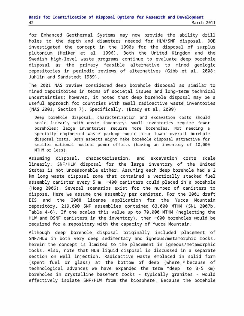
Summary and InsightMarch 2011 45
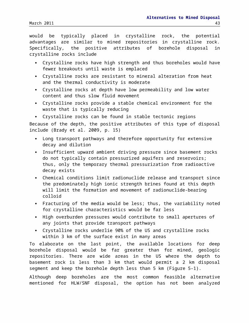
Basis for Identification of Disposal Options for Research and Development46 March 2011
8. REFERENCESAamot, H.W.C. 1967. The Philberth Probe for Investigating Polar Ice Caps, AD-661 049, U.S. Army Cold Regions
Research and Engineering Laboratory, Special Report 119.
Améglio, L., and J.L. Vigneresse. 1999. “Geophysical Imaging Of The Shape Of Granitic Intrusions At Depth: A Review,” in Castro, A., C. Fernández, and J.L.Vigneresse, eds., Understanding Granites: Integrating New and Classical Techniques, Geological Society Special Publication, No. 168, Whitstable, The Geological Society Publishing House.
ANDRA. 2005. Granite Synthesis Report – Interest for Granitic Formations for Geological Storage. Publications ANDRA.
Angino, E.E., G. Dreschhoff, and E.J. Zeller.1976. “Antarctica – A Potential International Burial Area for High-Level Radioactive Wastes”. Bull. Eng. Geol. 14: 173-178.
Anonymous. 1988. Feasibility of Disposal of High-Level Radioactive Wastes into the Seabed, Vol. 1: Overview of Research and Conclusions. Paris, France: Organization for Economic Cooperation and Development/Nuclear Energy Agency.
Apted, M. 2010. EPRI Review of Geologic Disposal for Used Fuel and High Level Radioactive Waste: Volume I – The U.S. Site Selection Process Prior to the Nuclear Waste Policy Amendments Act. Report 1021056. Palo Alto, CA: Electric Power Research Institute.
Apted, M., M. Kozak, M. Stenhouse, and A. Souder. 2010. EPRI Review of Geologic Disposal for Used Fuel and High Level Radioactive Waste: Volume IV – Lessons Learned. Report 1021057. Palo Alto, CA: Electric Power Research Institute.
Arnold, B., T. Hadgu, D. Clayton, and C. Herrick. 2011. “Thermal- Hydrologic-Chemical- Mechanical Modeling of Deep Borehole Disposal.” International High-Level Waste Radioactive Waste Management Conference, Albuquerque, NM April 10-14, 2011. LaGrange, IL: American Nuclear Society.
ATS 1959. The Antarctic Treaty. Washington, DC (December 1959).
Bair, E.S. 1987. “Analysis of Hydraulic Gradients across the Host Rock at the Proposed Texas Panhandle Nuclear-Waste Repository Site.” Ground Water, 25(4): 440-447.
Beauheim, R. L., and R. M. Roberts, 2002, Hydrology and Hydraulic Properties of a Bedded Evaporite Formation. Journal of Hydrology, 259(1-4):66-88.
BMWI (Federal Ministry of Economics and Technology). 2008. Final Disposal of High-Level Radioactive Waste in Germany—The Gorleben Project. Public Relations/IA8. Federal Ministry of Economics and Technology. www.bmwi.de.
BNWL. 1973. Overview of High-Level Radioactive Waste Management Studies. BNWL-1758. Richland, WA: Battelle Pacific Northwest Laboratories.
BRC. 2011. What We’ve Heard, A Staff Summary of Major Themes in Testimony and comments Received by the Blue Ribbon Commission on America’s Nuclear Future to Date. Washington, DC: Blue Ribbon Commission on America’s Nuclear Future, www.brc.gov.
BSC (Bechtel SAIC Company). 2004. Estimation of Mechanical Properties of Crushed Tuff for Use as Ballast Material in Emplacement Drifts. 800-CYC-SSE0-00100-000-00A. Las Vegas, Nevada: Bechtel SAIC Company.
Blomquist, R., J.Suksi, T.Ruskeeniemi, L. Ahonen, H. Niini, U. Vuorinen, and K. Jakobsson. 1995. The Palmottu Natural Analogue Project-The Behavior of Natural Radionuclides in and Around Uranium Deposits, Summary Report 1992-1994. STUK-YTO-TR 84, Finnish Centre for Radiation and Nuclear Safety.
Blümling, P., F. Bernier, P. Lebon, and C.D. Martin. 2007. “The Excavation-Damaged Zone in Clay Formations – Time-Dependent Behavior and Influence on Performance Assessment.” Physics and Chemistry of the Earth, Parts A/B/C. 32(8-14): 588-599.

ReferencesMarch 2011 47
Boeing. 1981. Analysis of Space Systems Study for the Space Disposal of Nuclear Waste. Study Report Volume 2 - Technical Report, Seattle, WA: Boeing Aerospace Co.
Bonano, E.J., P.A. Davis, L.R. Shipers, K.F. Brinster, W.E. Beyeler, C.D. Updegraff, E.R. Shepherd, L.M. Tilton, K.K. Wahi. 1989. Demonstration of a Performance Assessment Methodology for High-Level Radioactive Waste Disposal in Basalt Formations. NUREG/CR-4759, SAND86-2325. Albuquerque, NM: Sandia National Laboratories.
Bradshaw, R.L. and W.C McClain, eds. 1971. Project Salt Vault: A Demonstration of the Disposal of High-Activity Solidified Wastes in Underground Salt Mines. ORNL-4555. Oak Ridge, TN: Oak Ridge National Laboratory.
Brady, P.V, B.W. Arnold, G.A. Freeze, P.N. Swift, S.J. Bauer, J.L. Kanney, R.P. Rechard, and J.S. Stein. 2009. Deep Borehole Disposal of High-Level Radioactive Waste. SAND2009-4401. Albuquerque, NM: Sandia National Laboratories.
BRC (Blue Ribbon Commission). 2011. What We’ve Heard, A Staff Summary of Major Themes in Testimony and comments Received by the Blue Ribbon Commission on America’s Nuclear Future to Date. Washington, DC: Blue Ribbon Commission on America’s Nuclear Future, www.brc.gov.
Bredehoeft, J.D., A.W. England, D.B. Stewart, N.J. Trask, and I.J. Winograd. 1978. Geologic Disposal of High-Level Radioactive Waste: Earth-Science Perspectives. Circular 779. Reston, VA: US Geological Survey.
Brookins, D.G. 1985. “More on Radwaste Disposal”, Environmental Geology and Water Sciences, 7: 189-191.
Brush, L.H. 1988. Feasibility of Disposal of High-Level Radioactive Wastes into the Seabed, Vol. 7: Review of Laboratory Investigations of Radionuclide Migration through Deep-Sea Sediments. Paris, France: Organization for Economic Cooperation and Development/Nuclear Energy Agency.
Budd, W.F., D. Jenssen, and U. Radok. 1971. Derived Physical Characteristics of the Antarctic Ice Sheet. Pub. No. 18. Melbourne, Australia: University of Melbourne, Meteorology Department.
Bull, C. 1975, “Radioactive Waste Disposal”. Science, 189: 595.
Burns, R.E., W. E. Cuasey, W. E Galloway and R. W. Nelson. 1978. Nuclear Waste Disposal in Space. NASA-TP-1225. Huntsville, AL: Marshall Space Flight Center, NASA.
Bush, J. B. 1976. Economic and Technical Feasibility Study of Compressed Air Storage. ERDA 76-76. Schenectady, NY: General Electric Company
Carter, L.J. 1987. Nuclear Imperatives and Public Trust: Dealing with Radioactive Waste. Resources for the Future. Baltimore, MD: John Hopkins University Press.
Chapman, N.A. 2006.“Geological Disposal of Radioactive Wastes – Concept, Status and Trends”, Journal of Iberian Geology, 32: 7-14.
Christl, R.J. 1964. Storage of Radioactive Waste in Basement Rock beneath the Savannah River Plant. DP-844. Aiken, SC: E.I. dupont de Nemours & Co, Savannah River Laboratory.
CNEA. 1990. “Estudio de Factibilidad y Anteproyecto de Ingeniería – Repositorio de Residuos Radiactivos de Alta Actividad. (1ª Parte)”. Comisión Nacional de Energía Atómica.
Cobbs, J.H., Engineering. 1976. Survey of Active and Inactive Mines for Possible Use as In Situ Test Facilities. Y/OWI/Sub-76/16514. Oak Ridge, TN: Oak Ridge National Laboratory.
Cobbing, J. 2000. The Geology and Mapping of Granite Batholith, Berlin: Springer
Cochran, J.R., W.E. Beyeler, D.A. Brosseau, L.H. Brush, T.J. Brown, B.M. Crowe, S. H. Conrad, P.A. Davis, T. Ehrhorn, T. Feeney, B. Fogleman, D.P. Gallegos, R. Haaker, E. Kalinina, L.L. Price, D.P. Thomas, S. Wirth. 2001. Compliance Assessment Document for the Transuranic Wastes in the Greater Confinement Disposal Boreholes at the Nevada Test Site, Volume 2: Performance Assessment. SAND2001-2977. Albuquerque, NM: Sandia National Laboratories.
Colarusso, A., B. Crowe, and J.R Cochran. 2003. “Completion of the Transuranic Greater Confinement Disposal Borehole Performance Assessment for the Nevada Test Site.” WM’03 Conference, February 23-27, 2003, Tucson, AZ.

Basis for Identification of Disposal Options for Research and Development48 March 2011
Cosma, C., O. Olsson, J. Keskin, and P. Heikkinen. 2001. “Seismic Characterization of Fracturing at the Äspö Hard Rock Laboratory, from fhe Kilometer Scale to the Meter Scale”, International Journal of Rock Mechanics & Mining Sciences 38: 859 – 865.
Deal, D.E., R.J. Abitz, D.S. Belski, J.B. Case, M.E. Crawley, C.A. Givens, P.P.J. Lipponner, D.J. Milligan, J.Myers, D.W. Powers, and M.A. Valdivia. 1995. Brine Sampling and Evaluation Program, 1992-1993 Report and Summary of BSEP Data since 1982.
DeConto, R.M., and D. Pollard. 2003. “Rapid Cenozoic Glaciation of Antarctica Induced by Declining Atmospheric CO2,” Nature, 421: 245-249
Dewhurst, D.N., Y. Yang, and A.C. Aplin, 1999. Muds and Mudstones: Physical and Fluid Flow Properties, pp. 23-43, A.C. Aplin, A.J. Fleet, and J.H.S. MacQuaker, Eds., Geological Society, London, Special Publications 158.
DOE (Department of Energy). 1980. Final Environmental Impact Statement, Management of Commercially Generated Radioactive Waste, Volume 1. DOE/EIS-0046F-V.1. Washington, DC: US Department of Energy.
DOE (Department of Energy). 1984. Draft Environmental Assessment: Yucca Mountain Site, Nevada Research and Development Area, Nevada. DOE/RW-0012. Washington, DC: US Department of Energy.
DOE (Department of Energy). 1986a. Recommendation by the Secretary of Energy of Candidate Sites for Site Characterization for the First Radioactive-Waste Repository. DOE/S-0048. Washington, DC: US Department of Energy.
DOE (Department of Energy). 1986b. A Multiattribute Utility Analysis of Sites Nominated for Characterization for the First Radioactive-Waste Repository – A Decision-Aiding Methodology. DOE/RW-0074. Washington DC: Office of Civilian Radioactive Waste Management, US Department of Energy.
DOE (Department of Energy). 1986c. Nuclear Waste Policy Act (Section 112), Environmental Assessment, Deaf Smith County Site, Texas.
DOE (Department of Energy). 1986d. Draft Area Recommendation Report for the Crystalline Repository Project. DOE/CH-15(0). Washington DC: Crystalline Repository Project Office, Office of Civilian Radioactive Waste Management, US Department of Energy.
DOE (Department of Energy). 2004. Title 40 CFR Part 191 Compliance Recertification Application for the Waste Isolation Pilot Plant. DOE/WIPP 2004-3231. Carlsbad, NM: Waste Isolation Pilot Plant, Carlsbad Field Office, US Department of Energy.
DOE (Department of Energy). 2008a, Yucca Mountain Repository License Application, Safety Analysis Report. DOE/RW-0573, Update No. 1, November, 2008. Las Vegas, NV: Office of Civilian Radioactive Waste Management, US Department of Energy
DOE (Department of Energy). 2008b. The Report to the President and the Congress by the Secretary of Energy on the Need for a Second Repository. DOE/RW-0595. Washington, DC: US Department of Energy.
Ekren, E.B., G.A. Dinwiddie, J.W. Mytton, W. Thordarson, J.E. Weir, E.N. Hinrichs, L.J. Schroder. 1974. Geologic and Hydrologic Considerations for Various Disposal Concepts of High-Level Radioactive Waste Disposal in Conterminous United States. Open-File Report 74-158. Reston, VA: US Geological Survey.
EPA Environmental Protection Agency). 1985. “40 CFR Part 191 Environmental Standards for the Management and Disposal of Spent Nuclear Fuel, High-Level and Transuranic Radioactive Wastes: Final Rule.” Federal Register, 50(182): 38066-38089.
ERDA (Energy Research and Development Administration). 1976. Alternatives for Managing Wastes from Reactors and Post-Fission Operations in the LWR Fuel Cycle. ERDA-76-43. Richland, WA: Battelle Pacific Northwest Laboratories.
Flowers, B. 1976. Nuclear Power and the Environment, Sixth Report. London: Royal Commission on Environmental Pollution. Her Majesty's Stationery Office.
CG (Comptroller General of the United States). 1979. The Nation’s Nuclear Waste – Proposals for Organization and Siting. Washington, DC.
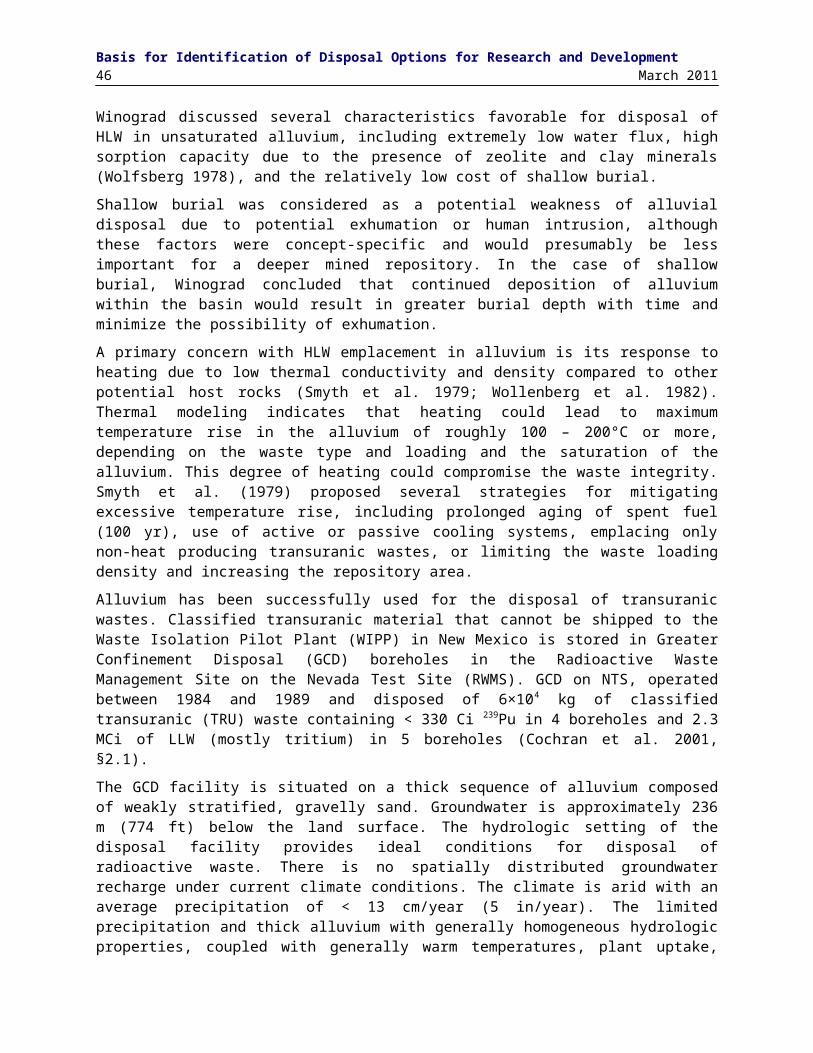
ReferencesMarch 2011 49
Garisto, F., T. Kempe, and P. Gierszewski. 2009. Technical Summary of the Safety Aspects of the Deep Geological Repository Concept for Used Nuclear Fuel. NWMO TR-2009-12. Toronto, Ontario: Nuclear Waste Management Organization,
Gibb, F. G.F., N.A. McTaggart, et al. 2008. "High-Density Support Matrices: Key to the Deep Borehole Disposal of Spent Nuclear Fuel." J. of Nuclear Materials 374: 370-377.
Gonzales, S. 1975. Geologic Feasibility of Selected Chalk-Bearing Sequences within the Conterminous United States with Regard to Siting of Radioactive Waste Repositories. Y/OWI/Sub-4310/2. Oak Ridge, TN: Oak Ridge National Laboratory.
Gonzales, S. 1977. Supplemental Field and Literature Investigation of the Upper Cretaceous Austin Group (Chalk) of Texas with Regard to Its Potential for Radioactive Waste Isolation. Y/OWI/Sub-310/4. Oak Ridge, TN: Oak Ridge National Laboratory.
Gonzales, S. and K.S. Johnson. 1984. Shale and Other Argillaceous Strata in the United States. ORNL/Sub/84-64794/1. Oak Ridge, TN: Oak Ridge National Laboratory.
Gere, F., and D.G. Jacobs. 1972. Considerations in the Long-Term Management of High-Level Radioactive Wastes. ORNL-4762. Oak Ridge, TN: Oak Ridge National Laboratory.
Guggenheim, S., and R.T. Martin. 1995. “Definition of Clay and Clay Mineral; Joint Report of the AIPEA Momenclature and CMS Nomenclature Committees.” Clays and Clay Minerals, 43(2): 255-256.
Hansen, F. D, 2003, The Disturbed Rock Zone at the Waste Isolation Pilot Plant. SAND2003-3407. Sandia National Laboratories, Albuquerque, NM.
Hansen, F.D., E.L. Hardin, R. P. Rechard, G. A. Freeze, D.C. Sassani, P.V. Brady, C. M. Stone, M. J. Martinez, J. F. Holland, T. Dewers, K.N. Gaither, S. R. Sobolik, and R. T. Cygan. 2010a. Shale Disposal of U.S. High-Level Radioactive Waste. SAND2010-2843. Albuquerque, NM: Sandia National Laboratories.
Hansen, F.D., E.L. Hardin, and A. Orrell. 2010b. “Geologic Disposal Options in the USA.” International High-Level Waste Radioactive Waste Management Conference, Albuquerque, NM April 10-14, 2011 . LaGrange, IL: American Nuclear Society.
Hansen, F.D., and C. D. Leigh. 2011. Salt Disposal of Heat-Generating Nuclear Waste. SAND2011-0161. Albuquerque, NM: Sandia National Laboratories.
Heiken, G., G. WoldeGabriel, R. Moreley, H. Plannerer, and J.Rowley.1996. Disposition of Excess Weapon Plutonium In Deep Boreholes. LA-13168-MS. Los Alamos, NM: Los Alamos National Laboratory.
Hickerson, J., T.J. Freeman, J.Y. Boisson, C.N. Murray, F. Gera, H. Nakamura, J.D. Nieuwenhuis, and K.H. Schaller. 1988. Feasibility of Disposal of High-Level Radioactive Wastes into the Seabed, Vol. 4: Engineering. Paris, France: Organization for Economic Cooperation and Development/Nuclear Energy Agency.
Hoag, C.I. (2006). Canister Design for Deep Borehole Disposal of Nuclear Waste. Cambridge, MA: Department of Nuclear Engineering, Massachusetts Institute of Technology.
Houseworth, J.E. 2011. “Natural Disturbances of Argillaceous Caprock Integrity.” International High-Level Waste Radioactive Waste Management Conference, Albuquerque, NM, April 10-14, 2011. LaGrange, IL: American Nuclear Society.
IAEA (International Atomic Energy Agency). 1998. Technical, Institutional and Economic Factors Important for Developing a Multinational Radioactive Waste Repository. IAEA-TECDOC-1021. Vienna, Austria: International Atomic Energy Agency.
IAEA (International Atomic Energy Agency). 2001. The Use of Scientific and Technical Results from Underground Research Laboratory Investigations for the Geological Disposal of Radioactive Waste . IAEA-TECDOC- 1243. Vienna, Austria: International Atomic Energy Agency.
IAEA (International Atomic Energy Agency). 2004. Developing Multinational Radioactive Waste Repositories: Infrastructural Framework and Scenarios of Cooperation. IAEA-TECDOC-1413. Vienna, Austria: International Atomic Energy Agency.

Basis for Identification of Disposal Options for Research and Development50 March 2011
IRG. 1979. Report to the President by the Interagency Review Group on Nuclear Waste Management. TID-29442. Washington, DC: U.S. Department of Energy.
Johnson, R.T. and E.C. Donaldson. 1973. “Well Injection System for Industrial Waste.” In Water-1972, American Institute of Chemical Engineers Symposium Series 219, Vol. 69, p. 336, New York, NY.
Johannesson, L.E., L. Borgesson, R. Goudarzi, and T. Sanden. 200, “Prototype Repository: A Full Scale Experiment at ASPO HRL.” Physics and Chemistry of the Earth, 32: 58-76.
Johnson, K.S., and S. Gonzales. 1978. Salt Deposits in the United States and Regional Geologic Characteristics Important for Storage of Radioactive Waste. Y/OWI/SUB-7414/1. Athens, GA: Earth Resources Associates.
Joy, H., T. Longo, and E.S. Burton. 1985. “Review of Site Recommendation Process in Draft Environmental Assessments,” Proceedings of the Symposium on Waste Management at Tucson, Arizona, March 24-28, 1985 , R.G. Post, Ed.
Juhlin, C. and H. Sandstedt. 1989. Storage of Nuclear Waste in Very Deep Boreholes: Feasibility Study and Assessment of Economic Potential. Part I: Geological Considerations. Part II: Overall Facility Plan and Cost Analysis. Svensk Karnbranslehantering AB (SKB).
Kedrovskii, O.L., A.I. Rybal'chenko, M.K. Pimenov, P.P. Kostin, V.M. Kurochkin, N.N. Egorov, A.A. Samarkin, A.V. Nosukhin, A.V. Mitryushin, A.S. Ladzin, and I.M. Kosareva. 1990. “Deep Burial of Liquid Radioactive Waste in Porous Geologic Formations,” Atomnaya Energiya, 70(5): 298-303.
Klett, R.D. Deep Rock Nuclear Waste Disposal Test: Design and Operation. SAND74-0042. Albuquerque, NM: Sandia National Laboratories.
Kozak, M. 2010. EPRI Review of Geologic Disposal for Used Fuel and High Level Radioactive Waste: Volume II U.S. Regulations for Geologic Disposal. Report 1021384. Palo Alto, CA: Electric Power Research Institute.
Kubo, A.S. and D.J. Rose. 1973. “Disposal of Nuclear Wastes.” Science, 182(4118): 1205-1211.
Krumhansl, J.L. 1983. “Near-surface heater test results: Environmental implications for the disposal of high-level waste.” Radioactive Waste Management and the Nuclear Fuel Cycle, 4(1): 1-31.
Lanza, F. 1988. Feasibility of Disposal of High-Level Radioactive Wastes into the Seabed, Vol. 8: Review of Processes near a Buried Waste Canister. Paris, France: Organization for Economic Cooperation and Development/Nuclear Energy Agency.
Lappin, A.R., R.K. Thomas, and D.F. McVey. 1981. Eleana Near-Surface Heater Experiment, Final Report. SAND 80-2137. Albuquerque, NM: Sandia National Laboratories.
LeGros, P.G., C.E. Gustafson, G.L. Nevill, E.C. Majeske, R.D. Mathews, J.S. Talbot, and W.F. McIlhenny. 1969. A Study of Deep-Well Disposal of Desalination Brine Waste. Progress Report No. 456. Office of Saline Water Research and Development, US Department of Interior.
Lewis, A.E., Cohen, J.J., Braun, R.L., and Rothman, A.J. 1972. “Placement and Self-Processing of Nuclear Processing Wastes in Deep Underground Cavities.” UCRL-73818. Symposium on the Management of Radioactive Wastes from Fuel Reprocessing, Paris, France, November 27 – December 1, 1972.
Little, R., J. Avis, N. Calder, N. Garisto, P. Humphreys, F. King, L. Limer, R. Metcalfe, J. Penfold, J. Rees, D. Savage, P. Suckling, G. Towler, R. Walke and R. Walsh. 2009. Deep Geologic Repository for OPG’s Low and Intermediate Level Waste-Postclosure Safety Assessment (VI) Report, NWMO DGR-TR-2009-01.
Lomenick, T.F. 1996. The Siting Record: An Account of the Programs of Federal Agencies and Events That Have Led to the Selection of a Potential Site for a Geologic Repository for High-Level Radioactive Waste. ORNL-TM-12940. Oak Ridge, TN: Oak Ridge National Laboratory.
de Laguna, W., T.Tamura, H.O. Weeren, E.G. Struxness, W.C. McClain, and R.C. Sexton. 1968. Engineering Development of Hydraulic Fracturing as a Method for Permanent Disposal of Radioactive Wastes. ORNL-4259, Oak Ridge, TN: Oak Ridge National Laboratory.
de Laguna W., 1972. Hydraulic Fracturing Test at West Valley, New York. ORNL-4827. Oak Ridge, TN: Oak Ridge National Laboratory.
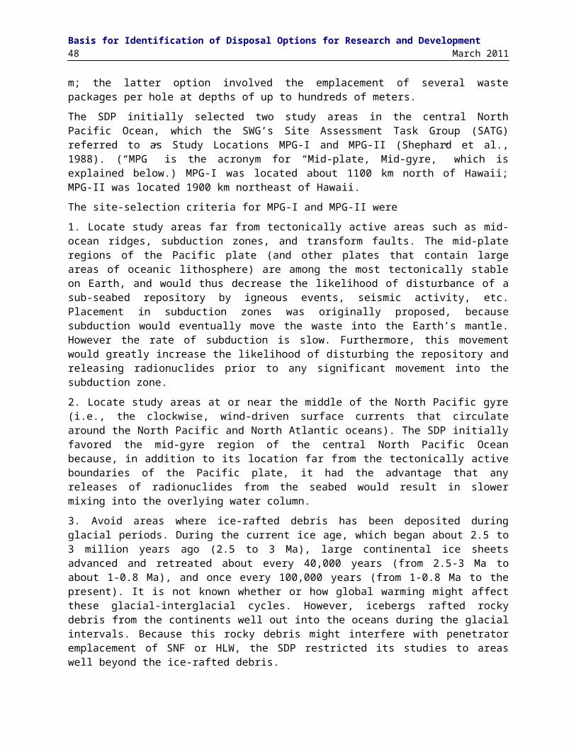
ReferencesMarch 2011 51
Marietta, M.G., and W.F. Simmons. 1988. Feasibility of Disposal of High-Level Radioactive Wastes into the Seabed, Vol.5: Dispersal of Radionuclides in the Oceans: Model Data Sets and Regional Descriptions. Paris, France: Organization for Economic Cooperation and Development/Nuclear Energy Agency.
de Marsily, G., V. Berhendt, D. Ensminger, C. Flebus, B. Hutchinson, P. Kane, A. Karpf, R. Klett, S. Mobbs, M. Poulin, and D. Stanner. 1988. Feasibility of Disposal of High-Level Radioactive Wastes into the Seabed, Vol. 2: Radiological Assessment. Paris, France: Organization for Economic Cooperation and Development/ Nuclear Energy Agency.
MIT (Massachusetts Institute of Technology). 2006. The Future of Geothermal Energy. Cambridge, MA: Massachusetts Institute of Technology.
Matalucci, R. V. 1988. In-Situ Testing at the Waste Isolation Pilot Plant. SAND87-2382. Albuquerque, NM: Sandia National Laboratories.
McClain, W.C., T.F. Lomenick, and R.S. Lowrie. 1975. Geologic Disposal Evaluation Program, Semi Annual Report. ORNL-5052. Oak Ridge, TN: Oak Ridge National Laboratory
McKinley, I. G., W. R. Alexander, and P. C. Blaser 2007. Development of Geological Disposal Concepts, Radioactivity in the Environment. W. R. Alexander and I. G. McKinley (eds.). Elsevier, Amsterdam. p. 41-76.
Migon, P. 2006. Granite Landscapes of the World, Oxford: Oxford University Press.
Montgomery, C.T. and M.B. Smith. 2010. “Hydraulic Fracturing: History of an Enduring Technology”. Journal of Petroleum Technology, 62(12): 26–32.
NAS (National Academy of Sciences-National Research Council). 1957. The Disposal of Radioactive Waste on Land, Publication 519, Washington DC: National Academy Press.
NAS (National Academy of Sciences-National Research Council). 1966. Review of the Radioactive Waste disposal Technology Report to the Division of Reactor Development and Technology. Washington, DC: National Academy Press.
NAS (National Academy of Sciences-National Research Council). 1970. Disposal of Solid Radioactive Wastes in Bedded Salt Deposits. Washington, DC: National Academy Press.
NAS (National Academy of Sciences-National Research Council). 1978. Geological Criteria for Repositories for High-Level Radioactive Wastes. Washington, DC: National Academy Press.
NAS (National Academy of Sciences-National Research Council). 1983. A Study of the Isolation System for Geologic Disposal of Radioactive Wastes. Washington, DC: National Academy Press.
NAS (National Academy of Sciences-National Research Council). 2001. Disposition of High-Level Waste and Spent Nuclear Fuel: The Continuing Societal and Technical Challenges. Washington, DC: National Academy Press.
NEA (Nuclear Energy Agency). 2006. Advanced Nuclear Fuel Cycles and Radioactive Waste Management. NEA No. 590. Organization for Economic Co-operation and Development (OECD).
NWPA (Nuclear Waste Policy Act of 1982). 1983. Pub. L. 97-425, 96 Stat. 2201; 42 U.S.C. 10101 et. seq.
NWTRB (Nuclear Waste Technical Review Board). 2009. Survey of National Programs for Managing High-Level Radioactive Waste and Spent Nuclear Fuel, A Report to Congress and the Secretary of Energy . Arlington, VA: Nuclear Waste Technical Review Board.
ORNL (Oak Ridge National Laboratory). 1986. Proceedings of the First Thermomechanical Workshop for Shale. ORNL/Sub/85-97343/1.
OTA (Office of Technology Assessment). 1982. Managing Commercial High-Level Radioactive Waste. Washington, DC: U.S. Government Printing Office.
OTA (Office of Technology Assessment). 1985. Managing the Nation’s Commercial High-Level Radioactive Waste. OTA-O-171.Washington, DC: Office of Technology Assessment. U.S. Government Printing Office. www.fas.org/ota

Basis for Identification of Disposal Options for Research and Development52 March 2011
Patrick, W. C. 1986. Spent-Fuel Test - Climax: An Evaluation of the Technical Feasibility of Geologic Storage of Spent Nuclear Fuel in Granite. Executive Summary of Final Results. UCRL-53762. Livermore, CA: Lawrence Livermore National Laboratory.
Paterson, W.S.B. 1976. “Radioactive Waste Disposal in Antarctica: Some Glaciological Aspects”. Modern Geology, 6: 37-42.
Patterson, B.D., S.A. Dave, and W.J. O’Connell. 1980. “Nuclear Waste Management: Storage and Disposal Aspect.” UCRL-84918l. Livermore, CA: Lawrence Livermore National Laboratory.
Pentreath, R.J., B.T. Hargrave, H.S.J. Roe, and M. Sibuet. 1988. Feasibility of Disposal of High-Level Radioactive Wastes into the Seabed, Vol. 6: Deep-Sea Biology, Biological Processes, and Radiobiology. Paris, France: Organization for Economic Cooperation and Development/Nuclear Energy Agency.
Perkins, B.L. 1982. Disposal of Liquid Radioactive Wastes through Wells or Shafts. LA-9142-MS. Los Alamos, NM: Los Alamos National Laboratory.
Pierce, W.G., and E.I. Rich. 1962. Summary of Rock Salt Deposits in the United States as Possible Storage Sites for Radioactive Waste Materials. Bulletin 1148. Washington, DC: US Geological Survey
Pittman, F.K. 1974. High-Level Radioactive Waste Management Alternatives. WASH-1297. Washington DC: Atomic Energy Commission.
Philberth, B. 1958. “Disposal of Atomic Fission Products in Polar Ice Caps.” AHS Symposium.
Philberth, B.. 1961. “Beseitigung radioaktiver Abfallsubstan- zen in den Eiskappen der Erde”. Schweizerische Zeits. f. Hydrologie, Fasc. 1, p. 262-284.
Pomiès, C., B. Hamelin, J., Lancelot, and R.Blomqvist. 2004, “207Pb/206Pb And 238U/230Th Dating of Uranium Migration in Carbonate Fractures from the Palmottu Uranium Ore (Southern Finland)”. Applied Geochemistry, 19(3): 273-288.
Posiva 2010. Models and Data Report 2010. POSIVA 2010-01. Posiva Oy, Olkiluoto, Finland.
Rechard, R.P., ed. 1995. Performance Assessment of the Direct Disposal in Unsaturated Tuff of Spent Nuclear Fuel and High-Level Waste Owned by U.S. Department of Energy. Volumes 1, 2, and 3. SAND94-2563/1,2,3. Albuquerque, NM: Sandia National Laboratories.
Rechard, R.P. 2000. “Historical Background on Performance Assessment for the Waste Isolation Pilot Plant.” Reliability Engineering and System Safety, 69(1-3): 5-46.
Reed, J.C., Jr., and J.E. Harrison. 1993. “Introduction,” J.C. Reed, Jr., L.T. Silver, P.K. Sims, D.W. Rankin, R.S. Houston and M.W. Reynolds, (eds.), Geology of North America DNAG Project, Geological Society of America Vol. C 2, p. 1-10..
Rice, E.E. and C.C. Priest. 1981. “An Overview of Nuclear Waste Disposal in Space.” In The Technology of High-Level Nuclear Wastes. P.L. Hofmann . (Ed.). Vol. 1. DOE/TIC-4621. Oak Ridge, TN: Oak Ridge National Laboratory.
Roseboom, E.H. 1983. Disposal of High-Level Nuclear Waste above the Water Table in Arid Regions . Circular 903. Denver, CO: US Geological Survey.
Schneider, K.J., and A.M. Platt. Eds. 1974. High Level Radioactive Waste Management Alternatives. BNWL-1900. Richland, WA: Battelle Pacific Northwest Laboratories.
SKB (Swedish Nuclear Fuel and Waste Management Co.). 2000. What Requirements Does the KBS-3 Repository Make on the Host Rock? Geoscientific Suitability Indicators and Criteria for Siting snd Site Evaluation . SKB TR-00-12. Stockholm, Sweden: Svensk Kärnbränslehantering AB.
SKB (Swedish Nuclear Fuel and Waste Management Co.) 2006. Long-Term Safety for KBS-3 Repositories at Forsmark and Laxemar – A First Evaluation. Main Report of the SR-Can Project. SKB TR-06-09. Stockholm, Sweden: Svensk Kärnbränslehantering AB.
SKB (Swedish Nuclear Fuel and Waste Management Co.). 2008. Site Description of Forsmark at Completion of the Site Investigation Phase. SKB TR-08-05. Stockholm, Sweden: Svensk Kärnbränslehantering AB.

ReferencesMarch 2011 53
SNL (Sandia National Laboratories). 2008. Total System Performance Assessment Model/Analysis for the License Application. MDL-WIS-PA-000005 REV 00 ADD 01. Las Vegas, NV: Sandia National Laboratories.
SNL (Sandia National Laboratories). 2007. EBS Radionuclide Transport Abstraction. ANL-WIS-PA-000001 REV 03. Las Vegas, NV: Sandia National Laboratories.
SNL (Sandia National Laboratories) 2007b. Initial Radionuclide Inventories. ANL-WIS-MD-000020 REV 02. Las Vegas, NV: Sandia National Laboratories.
Shephard, L.E., G.A. Auffret, D.E. Buckley, R.T.E. Schüttenhelm, and R.C. Searle. 1988. Feasibility of Disposal of High-Level Radioactive Wastes into the Seabed, Vol. 3: Geoscience Characterization Studies. Paris, France: Organization for Economic Cooperation and Development/Nuclear Energy Agency.
Sims, P.K. 1993. “The Lake Superior Region and Trans-Hudson Orogen.” In Reed, J.C., Jr., et al., eds., The Geology of North America DNAG Project. Vol. C-2, p. 11-120.
Sinnock, S., J.A. Fernandez. 1982. Summary and Conclusions of the NNWSI Area-to-Location Screening Activity. SAND82-0650; NVO-247. Las Vegas, NV: U.S. Department of Energy, Nevada Operations Office.
Smedes, H.W. 1980. Rationale for Geologic Isolation of High-Level Radioactive Waste and Assessment of the Suitability of Crystalline Rocks. Open-File Report 80-1065. Reston, VA: US Geological Survey.
Smedes, H. W. 1983. A National Survey of Crystalline Rocks and Recommendations of Regions to be Explored for High-Level Radioactive Waste Repository Sites. Technical Report OCRD-1. Columbus, OH: Battelle Memorial Institute.
Smyth, J.R., B.M. Crowe, P.M. Halleck, and A.W. Reed. 1979. A Preliminary Evaluation of the Radioactive Waste Isolation Potential of the Alluvium-Filled Valleys of the Great Basin. LA-7962-MS. Los Alamos, NM: Los Alamos National Laboratory
SSM (Swedish Radiation Safety Authority). 2011. Website: http://www.stralsakerhetsmyndigheten.se/In-English/About-the-Swedish-Radiation-Safety-Authority1/The-Site-for-a-Spent-Nuclear-Fuel-Repository/Review-Process/ (Access date: March 16, 2011).
Starr, C., and R.P. Hammond. 1972. “Nuclear Waste Storage.” Science, 37: 744-745.
Stenhouse, M., M. Apted, and W. Zhou. 2010. EPRI Review of Geologic Disposal for Used Fuel and High Level Radioactive Waste: Volume III – Review of National Repository Programs. Report 1021614. Palo Alto, CA: Electric Power Research Institute.
Suksi, J., T. Ruskeeniemi, A. Lindberg and T. Jaakkola. 1991. “The Distribution of Natural Radionuclides on Fracture Surfaces in Palmottu Analogue Study Site in SW Finland”. Radiochimica Acta 52/53: 367-372.
Sun, R.G. 1974. Hydraulic Fracturing in Shale at West Valley, New York – A Study of Bedding-Plane Fractures Induced in Shale for Waste Disposal. 74-365. Reston, VA: US Geological Survey.
Szulinski, M.J., J.H. Warren, and O.J. Elgert. 1973. Engineered Storage of Radioactive Waste. Management of Radioactive Wastes from Fuel Reprocessing. Paris, France: Organization for Economic Cooperation and Development and International Atomic Energy Agency, pp. 791-812.
Trevorrow, L.E., D.L Warner, and M.J. Steindler. 1977. Considerations for the Application of Deep-Well Disposal to Tritium Bearing Low-Level Waste from Nuclear Fuel Reprocessing Plants. ANL-76-76 Argonne, IL: Argonne National Laboratory.
Twidale, C.R. and J.R. Vidal-Romani. 2005. Landforms and Geology of Granite Terrains, Leiden, A.A. Balkema Publishers.
Vandenbosch, R., and S.E. Vandenbosch. 2007. Nuclear Waste Stalemate: Political and Scientific Controversies. Salt Lake City, UT: University of Utah Press.
Van Schmus, W.R. and M.E. Bickford. 1993, “Transcontinental Proterozoic Provinces,” In Reed, J.C., Jr., et al., eds., The Geology of North America DNAG Project. Vol. C-2, p. 171-334.
Wagoner, J. 1999. Fracture Characterization of the Large-Block Test, Fran Ridge, Yucca Mountain, Nevada . UCRL-ID-133846. Livermore, CA: Lawrence Livermore National Laboratory.
Basis for Identification of Disposal Options for Research and Development54 March 2011
Walker, J.S. 2009. The Road to Yucca Mountain. Berkeley, CA: University of California Press.
Warner, D.L. 1972. Survey of Industrial Waste Injection Wells, Final Report. U.S. Geological Survey Contract No. 14-008-0001-12280.
Weeren, H.O. 1974. Shale Fracturing Injections at Oak Ridge National Laboratory - 1972 Series. ORNL-TM-4467. Oak Ridge, TN: Oak Ridge National Laboratory.
Whipple, C. 2010 (Updated 2/16/2011). Disposal of Spent Nuclear Fuel and High-level Radioactive Waste. Presented to the Blue Ribbon Commission on America’s Nuclear Future. http://brc.gov/library/commissioned_papers/Disposal%20of%20Spent%20Nuclear%20Fuel%20and%20High%20Level%20Radioactive%20Waste%20rev4.pdf
Winograd, I.J. 1974. “Radioactive Waste Storage in the Arid Zone”. EOS, 55: 884-894.
Winograd, I.J. 1981. “Radioactive Waste Disposal in Thick Unsaturated Zones.” Science, 212(4502): 1457-1464.
Wolfsberg, K. 1978. Sorption-Desorption Studies of Nevada Test Site Alluvium and Leaching Studies of Nuclear Test Debris. LA-7216-MS. Los Alamos, NM: Los Alamos National Laboratory.
Wollenberg, H.A., J.S.X. Wang, and G. Korbin. 1982. Nuclear-Waste Isolation in the Unsaturated Zones of Arid Regions. LBL-14086. Berkeley, CA: Lawrence Berkeley National Laboratory.
Woodward-Clyde Consultants. 1983. Very Deep Hole Systems Engineering Studies. Columbus, OH: Office of Nuclear Waste Isolation (ONWI).
Yavuz, H., S. Demirdag, and S. Caran. 2009. “Thermal Effect on the Physical Properties of Carbonate Rocks”. International Journal of Rock Mechanics & Mining Sciences 47(2010):94–103.
Young, R.P. and D.S. Collins. 2001. “Seismic Studies of Rock Fracture at the Underground Research Laboratory, Canada”, International Journal of Rock Mechanics and Mining Sciences, 38: 787-799.
Zeller, E.J., E.E. Angino, and D.F. Saunders. 1976. “Antarctica: A Potential Disposal Site for the World's High-Level Radioactive Waste”. Modern Geology, 6: 1-16.