Embed Size (px)
Citation preview


DOE/NE-ID-11158 Revision 0
Project No. 24057
Removal Action Work Plan for the Decontamination and Decommissioning of Building CPP-627, the
Remote Analytical Facility
June 2004
Prepared for the U.S. Department of Energy
DOE Idaho Operations Office

iii
ABSTRACT
This Removal Action Work Plan provides the methods and activities to conduct the decontamination and decommissioning of Building CPP-627 under a Comprehensive Environmental Response, Compensation and Liability Act non-time critical removal action. Building CPP-627 is part of the Fuel Reprocessing Complex located at the Idaho National Engineering and Environmental Laboratory. This plan addresses utility isolations, building decontamination and demolition, and reconstruction activities associated with the adjoining Fuel Reprocessing Complex facilities.
Alternatives for conducting this non-time critical removal action were evaluated in the Engineering Evaluation/Cost Analysis for the Decontamination and Decommissioning of Building CPP-627, the Remote Analytical Facility, (DOE/NE-ID-11157). The evaluation resulted in the recommendation to remove the building structure and its components to the concrete slab. This Removal Action Work Plan supports implementation of the non-time critical removal action.

iv

v
CONTENTS
ABSTRACT.................................................................................................................................................iii
ACRONYMS............................................................................................................................................... ix
1. INTRODUCTION.............................................................................................................................. 1
1.1 Purpose and Objective........................................................................................................... 1
1.2 Scope ..................................................................................................................................... 3
1.3 Removal Action Objectives................................................................................................... 3
1.4 Facility Background and Description.................................................................................... 4
2. REMOVAL ACTION WORK ACTIVITIES .................................................................................... 8
2.1 Work Preparation................................................................................................................... 9
2.2 Mobilization .......................................................................................................................... 9
2.3 Characterization................................................................................................................... 10
2.4 Contamination Control ........................................................................................................ 10
2.5 Deactivation, Decontamination, and Decommissioning ..................................................... 11
2.5.1 Disposition of HWMA/RCRA –Regulated Piping ........................................... 12 2.5.2 RAF–A and B Line Shielded Analytical Caves ................................................ 12 2.5.3 Old Shift Laboratory Dismantlement ................................................................ 16 2.5.4 Decon Development Laboratory and Emission Spectroscopy Laboratory ....... 16 2.5.5 Hot Chemistry Laboratory and Multicurie Cell ................................................ 17 2.5.6 Building Structure Dismantlement.................................................................... 17
2.6 Reconstruction Activities/Site Restoration.......................................................................... 18
2.7 Demobilization .................................................................................................................... 18
3. FACILITY HAZARDS .................................................................................................................... 19
3.1 Hazard Assessment.............................................................................................................. 19
3.1.1 Radiological Materials ...................................................................................... 19 3.1.2 Hazardous Material Inventory........................................................................... 20 3.1.3 Direct Radiation Exposures............................................................................... 20 3.1.4 Other Criteria Not Requiring Additional Safety Analysis ................................ 20
3.2 Hazard Classification........................................................................................................... 20
4. STRUCTURES, SYSTEMS, AND COMPONENTS THAT PROTECT FACILITY WORKERS....................................................................................................................................... 21

vi
5. SAFETY AND HEALTH MANAGEMENT CONTROLS............................................................. 22
5.1 Health and Safety Program.................................................................................................. 22
5.1.1 Site-Specific Health and Safety Plan and Activity Hazard Analysis ................ 22
6. ENVIRONMENTAL MANAGEMENT AND CONTROLS .......................................................... 23
6.1 Applicable or Relevant and Appropriate Requirements...................................................... 23
6.2 Waste Management and Disposal........................................................................................ 30
6.3 Natural and Cultural Resource Protection........................................................................... 31
7. PROJECT MANAGEMENT AND ORGANIZATION .................................................................. 32
7.1 Organization Chart .............................................................................................................. 32
7.2 Project Schedule and Cost Estimate .................................................................................... 32
7.3 Conduct of Operations......................................................................................................... 33
7.4 Change Management/Configuration Control ...................................................................... 35
7.5 Quality Assurance Requirements ........................................................................................ 35
8. PROJECT CLOSEOUT ................................................................................................................... 36
9. REFERENCES................................................................................................................................. 37
Appendix A—CPP-627 Removal Action RCRA Regulated Piping........................................................... 39
Appendix B—Drawing of A&B Line Waste End....................................................................................... 45
Appendix C—Drawing of A&B Line Shielded Cells................................................................................. 47
FIGURES
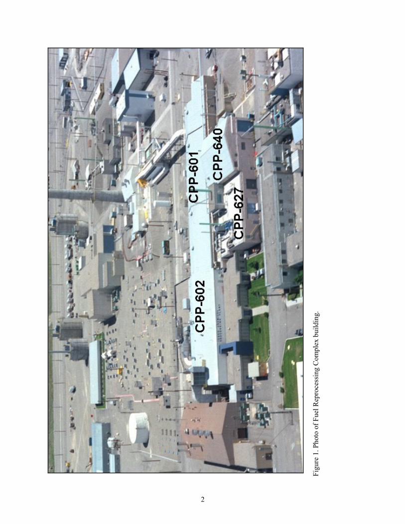
1. Photo of Fuel Reprocessing Complex Building ................................................................................. 2
2. Location of the Idaho Nuclear Technology and Engineering Center on the Idaho National Engineering and Environmental Laboratory Site ............................................................................... 5
3. Plan view of the Idaho Nuclear Technology and Engineering Center ............................................... 6
4. Isometric view of Building CPP-627.................................................................................................. 7
5. Floor plan of CPP-627 A&B lines.................................................................................................... 13
6. AutoCAD drawing of CPP-627 A&B lines in the RAF................................................................... 14

vii
7. Organization chart for the CPP-627 removal action......................................................................... 32
8. CPP-627 decontamination and decommissioning project schedule ................................................. 34
TABLES
1. Summary of applicable or relevant and appropriate requirements for the CPP-627 non-time critical removal action .................................................................................................................................. 24
2. Expected waste streams and volumes for CPP-627.......................................................................... 30
3. Cost estimate for removal action ...................................................................................................... 33
4. Major removal action activities/deliverables schedule..................................................................... 33

viii

ix
ACRONYMS
ALARA as low as reasonably achievable
AOC area of contamination
ARAR applicable or relevant and appropriate requirement
CERCLA Comprehensive Environmental Response, Compensation and Liability Act
CFA Central Facilities Area
D&D decontamination and decommissioning
DD&D deactivation, decontamination, and decommissioning
DDL Decon Development Laboratory
DEQ Idaho Department of Environmental Quality
DOE Department of Energy
DOE Idaho Department of Energy, Idaho Operations Office
EPA Environmental Protection Agency
ESL Emission Spectroscopy Laboratory
HCL Hot Chemistry Laboratory
HEPA high-efficiency particulate air
HVAC heating, ventilating, and air conditioning
HWMA Hazardous Waste Management Act
ICDF INEEL CERCLA Disposal Facility
INEEL Idaho National Engineering and Environmental Laboratory
INTEC Idaho Nuclear Technology and Engineering Center
JSA job safety analysis
MCC Multicurie Cell
OSL Old Shift Laboratory
OU operable unit
PAPR powered air-purifying respirators
PCB polychlorinated biphenyl
PEWE Process Equipment Waste Evaporator (System)
RAF Remote Analytical Facility
RCRA Resource Conservation and Recovery Act

x
ROD Record of Decision
RWP radiological work permit
SSA Staging and Storage Annex
TSDF Treatment, Storage, and Disposal Facility
WAC Waste Acceptance Criteria
WAG waste area group

1
Removal Action Work Plan for the Decontamination and Decommissioning of Building CPP-627, the
Remote Analytical Facility 1. INTRODUCTION
This Removal Action Work Plan addresses the removal of Building CPP-627, the Remote Analytical Facility (RAF), which is a part of the Fuel Reprocessing Complex at the Idaho Nuclear Technology and Engineering Center (INTEC) (see Figure 1) at the U.S. Department of Energy’s (DOE’s) Idaho National Engineering and Environmental Laboratory (INEEL), Butte County, Idaho. This removal action is being conducted under an Action Memorandum reviewed by the U.S. Environmental Protection Agency (EPA) Region 10 and the Idaho Department of Environmental Quality (DEQ). The DOE Idaho Operations Office (DOE Idaho) has determined that hazardous and radioactive substances in Building CPP-627 present a potential threat to human health or the environment. DOE Idaho has also determined that a non-time critical removal action is warranted to address those potential threats.
The Comprehensive Environmental Response, Compensation and Liability Act (CERCLA) Operable Unit (OU) 3-13 Record of Decision (ROD) (DOE-ID 1999) governs CERCLA sites within the INTEC facility designated as Waste Area Group (WAG) 3. This CERCLA removal action, therefore, is subject to the remedial action objectives established in the OU 3-13 ROD.
Alternatives for conducting a non-time critical removal action were evaluated in the Engineering Evaluation/Cost Analysis for the Decontamination and Decommissioning of Building CPP-627, the Remote Analytical Facility (DOE-ID 2004a). That engineering evaluation/cost analysis has been developed in accordance with the “Comprehensive Environmental Response, Compensation and Liability Act of 1980,” as amended by the “Superfund Amendments and Reauthorization Act of 1986,” (42 USC 9601) and in accordance with the “National Oil and Hazardous Substances Pollution Contingency Plan” (40 CFR 300). The evaluation resulted in the recommendation to decontaminate and remove the building and its contents and dispose of the waste in an appropriate disposal facility. The recommendation was approved in an Action Memorandum (DOE-ID 2004b) signed by DOE with concurrence from the EPA and DEQ.
1.1 Purpose and Objective The purpose of this Removal Action Work Plan is to establish the methods and activities to
perform the following removal action functions:
• Complete decontamination and decommissioning (D&D) of the CPP-627 building and its components down to the concrete slab
• Modify Buildings CPP-601, -602, and -640, which are attached to CPP-627, to place the buildings in a safe state
• Manage and dispose of wastes generated during these actions
• Minimize and manage air emissions to protect workers and the environment.
This removal action will reduce the risks to human health, the environment, and site workers by minimizing the potential for release of hazardous and radioactive substances, through removal of the waste and disposal of Building CPP-627 down to its concrete slab. The concrete slab varies in thickness from 6 in. to 1 ft 6 in., except under the Multicurie Cell (MCC), where the thickness is 5 ft. The
2
Figu
re 1
. Pho
to o
f Fue
l Rep
roce
ssin
g C
ompl
ex b
uild
ing.

3
concrete thickness estimates do not include the concrete footings. The waste generated through the demolition of Building CPP-627 will be CERCLA radioactive, hazardous, or mixed radioactive and hazardous waste. The preferred disposal facility for this waste is the INEEL CERCLA Disposal Facility (ICDF). Some waste, such as piping from Hazardous Waste Management Act (HWMA)/Resource Conservation and Recovery Act (RCRA) -regulated systems, will be disposed of at an off-Site RCRA-compliant Treatment, Storage, and Disposal Facility (TSDF).
1.2 Scope
The primary goal of CERCLA removal actions is to minimize or eliminate threats to public health or the environment caused by the presence of hazardous and radioactive substances. The engineering evaluation/cost analysis for CPP-627 presented two alternative approaches for future facility management and the resulting levels of protection of public health and the environment that may be anticipated. Based on the evaluation, the removal alternative, demolishing the building and its components down to the concrete foundation, was recommended as the most responsive approach to ensure protection of human health and the environment. The selection and approval of this approach are documented in the Action Memorandum (DOE-ID 2004b) for Building CPP-627.
The scope of the approved removal action includes Building CPP-627, a part of a larger complex of buildings called the Fuel Reprocessing Complex, shown in Figure 1. The Fuel Reprocessing Complex reprocessed spent nuclear fuel. Hazard removal, demolition, and disposal of the building and its components will reduce the potential hazards to public health or the environment that are currently posed by CPP-627. Waste products generated by this removal action will be separated into a variety of waste streams and disposed of at an appropriate disposal facility. Following removal of the structure, the concrete slab will be surveyed for any remaining radioactive contamination, and, if necessary, controls will be implemented to put the site in a stable condition that would preclude infiltration of water and migration of the contaminants below the slab. Consistent with the OU 3-13 ROD, Group 2, Soils Under Buildings, sites the soil beneath the slab will be evaluated during characterization of the Fuel Reprocessing Complex and is not part of this removal action.
1.3 Removal Action Objectives This proposed removal action is consistent with the CERCLA OU 3-13 ROD for WAG 3, thus
supporting the overall remediation goals at WAG 3.
Based on the selected alternative, the removal action objectives are as follows:
• Reduce the potential for worker exposure and the risk of a release of hazardous and/or radioactive contaminants to the air or to the subsurface during removal and disposal of the Building CPP-627 structure and contents down to the concrete slab floor to ensure a cumulative carcinogenic risk of 1 × 10⁻⁴ and a total Hazard Index of 1 are not exceeded
• Reduce the risk of contaminant migration to the underlying Snake River Plain Aquifer by removing the contaminant source in the CPP-627 structure so that the risk will not exceed a cumulative carcinogenic risk of 1 × 10⁻⁴ and a total Hazard Index of 1 for groundwater ingestion
• Prevent worker exposure, through new or continued engineering and institutional controls, to potential contaminants remaining in and under the CPP-627 concrete slab floor, after completion of the removal action and until the final remedial action for the Fuel Reprocessing Complex is implemented
4
• Prevent migration of contaminants remaining in and under the CPP-627 concrete slab floor to the Snake River Plain Aquifer, through new or continued engineering and institutional controls, after completion of the removal action and until the final remedial action for the Fuel Reprocessing Complex is implemented.
These removal action goals are consistent with the remedial action objectives established in the Final Record of Decision Idaho Nuclear Technology and Engineering Center, Operable Unit 3-13 (DOE-ID 1999). As such, the removal action will be consistent with and will contribute to the overall remediation of the INTEC under CERCLA.
1.4 Facility Background and Description The INTEC, located in the south-central area of the INEEL (Figures 2 and 3), began operations in
1952. Historically, spent nuclear fuel from defense projects was reprocessed to separate reusable uranium from spent nuclear fuel. In 1992, DOE discontinued reprocessing.
Building CPP-627 is part of the Fuel Reprocessing Complex, which reprocessed spent nuclear fuel. The Fuel Reprocessing Complex consisted of Buildings CPP-601, -627, and -640. Other buildings attached to the Fuel Reprocessing Complex include CPP-602, a laboratory and office building, and CPP-630, the Safety/Spectrometry Building. CPP-627 is a two-level, 14,727-ft2 facility constructed primarily of reinforced concrete. It shares common walls with the west side of CPP-601, the south side of CPP-602, and the north side of CPP-640. CPP-627 was constructed in 1955 to house analytical, experimental, and decontamination facilities. Utilities and waste collection were provided through the CPP-601 facility (Wagner 1999). While active use of the CPP-627 building ceased in 1997, the building still contains unknown quantities of various radiological and chemical hazardous substances, and the structure is aging and continues to degrade more rapidly each year. These hazardous substances include various radionuclides, lead, mercury, used oil, asbestos, cadmium, chromium, and other chemical residues. Two CERCLA sites are also located beneath the Fuel Reprocessing Complex. These sites, CPP-80 and CPP-86, are identified as Group 2 sites in the OU 3-13 ROD. Site CPP-80 resulted from a hazardous, radioactive liquid condensate leak from the Building CPP-601 vent tunnel drain. Site CPP-86 is a waste trench that runs beneath CPP-602 and collects liquid waste for transfer to the Process Equipment Waste Evaporator (PEWE) System from various CPP-602 operations. As buildings associated with Group 2 sites are removed, the OU 3-13 ROD identifies that the Agencies will perform an evaluation to determine whether the soils beneath the buildings contain contaminants exceeding the OU 3-13 action levels and to identify any follow-on actions that need to be performed.
The northern third of the building housed radiochemical analytical facilities. The RAF, consisting of two lines of shielded cells for remote sample preparation and analysis, was on the ground floor (see Figure 4). The Old Shift Laboratory (OSL), on the second floor, provided bench and hood space for chemical analysis of nuclear reactor fuel. The OSL operated in conjunction with the RAF to supply 24-hour analytical services in support of CPP-601 and calciner operations. Liquid wastes from the RAF and OSL were routed to the PEWE System in CPP-601. Sample residues containing uranium could be routed to the CPP-601 Uranium Salvage System.
Access to the two lines of shielded cells in the RAF is restricted because of high levels of radioactive and residual chemical contamination from the process used to dissolve nuclear fuel. Much of this contamination is shielded, using about 120 tons of radiologically contaminated lead (a toxic metal) in various shapes, sizes, and contamination levels (Wagner 1999). The OSL contained gloveboxes and fume hoods to analyze samples with low-to-moderate radioactivity and still remains highly contaminated with radionuclides and hazardous constituents similar to those in the RAF.

5
Figure 2. Location of the Idaho Nuclear Technology and Engineering Center on the Idaho National Engineering and Environmental Laboratory Site.

6
Fi
gure
3. P
lan
view
of t
he Id
aho
Nuc
lear
Tec
hnol
ogy
and
Engi
neer
ing
Cen
ter.

7
Legend A Special analysis laboratory (Shift Lab or Room 201) B, C, D Remote Analytical Facility (Room 102) B A-Line shielded analytical boxes D B-Line shielded analytical boxes E Decon Development Laboratory and Emission Spectroscopy Laboratory (Room 103) F, G, H Hot Chemistry Laboratory and Multi-Curie Cell F Multi-Curie Cell (Rooms 104 and 106) G, H Hot Chemistry Laboratory (Room 104) I Mass Criticality Control Area (Room 105)
Figure 4. Isometric view of Building CPP-627.

8
The middle third of Building CPP-627 was a high-bay decontamination facility, providing space for water and chemical cleaning of radiologically contaminated equipment. Liquid wastes were routed to the CPP-601 PEWE System. In 1980, the decontamination facility was removed and the area was rebuilt into the Emission Spectroscopy Laboratory (ESL) and the Decon Development Laboratory (DDL). Both facilities saw very limited use. The second story provided a fan and filter loft for air handling from some radioactively contaminated portions of the building.
The southern third of Building CPP-627 contained two experimental facilities, the Hot Chemistry Laboratory (HCL) and the MCC. The HCL consisted of lab benches, hoods, shielded gloveboxes, and a large walk-in hood used for the Custom Dissolution Process. The MCC was designed for experiments using fully irradiated fuel (including transuranic elements such as plutonium). The MCC was shielded to allow remote experiments on irradiated fuel or calcine. The MCC was also used as part of the Custom Dissolution Process. As in the rest of CPP-627, liquid wastes from the HCL and MCC were routed to the CPP-601 PEWE System, and uranium solutions were transferred to the CPP-601 Uranium Salvage System.
Radiological and hazardous material contamination remains in the building’s ventilation ducting and high-efficiency particulate air (HEPA) filter banks. Repairs were successfully made to the roof over the second-floor OSL because previous precipitation events caused the roof to leak, allowing radiological and hazardous substances to migrate within the building.
Through the years, waste piping at CPP-627 has been upgraded. Old lines were drained and capped during the CPP-601 Buried Line Replacement Project. Some of the lines, such as the piping installed in 1991 in the HCL and the MCC, were never put into service (Wagner 1999).
Building CPP-627 was taken out of service in 1997. Currently, the building is undergoing regular surveillance and maintenance to ensure that contaminants remaining in the building do not spread or expose workers.
Work has begun under the deactivation, decontamination, and decommissioning (DD&D) program to prepare the building for the CERCLA removal action. The Action Memorandum, signed on May 28, 2004, by DOE Idaho authorizes the project to be covered under the CERCLA process.

9
2. REMOVAL ACTION WORK ACTIVITIES
The following sections provide a general description of how work activities will be performed for the removal of Building CPP-627 and its components.
The general scope of work involved to implement this removal action includes the following activities:
• Removing hazardous and radioactive substances
• Removing facility equipment and piping
• Isolating utilities
• Dismantling the facility structure
• Disposing of waste
• Evaluating concrete slab for engineered cover
• Performing reconstruction activities
• Preparing a closeout report.
The work activities under this project will be performed in compliance with the applicable management control procedures that can be found on the INEEL intranet.
2.1 Work Preparation
Premobilization encompasses the activities performed before mobilization and removal action activities begin. Preplanning will include development of work packages to implement techniques such as surface fixation, material separation, and exhaust controls to maintain containment. In addition, when necessary, safe work permits, radiological work permits (RWPs), job safety analyses (JSAs), or other documentation may be written to comply with INEEL procedures and the requirements of this plan. The subcontracts for work activities such as saw-cutting will be in place. Requirements for training and medical information specified by the design specifications and INEEL-specific requirements will be completed as required. If required, documentation such as subcontractor bonds, subcontractor insurance, and proof that required training and medical examinations are complete will be provided in accordance with the Health and Safety Plan (INEEL 2003). These submittals certify that the project mobilization is ready to proceed. INEEL work control and JSAs will be completed before the notice is given to proceed, and the project will be placed on the INTEC Plan-of-the-Week schedule.
2.2 Mobilization
Mobilization is the work required in preparation of the removal action activities. This work generally implements the project and site-required administrative, engineering, and health and safety requirements. In preparation for work that must be done, temporary electrical supply systems, communication systems, and temporary water systems must be made available in the removal action construction area so that field labor and equipment can be mobilized. The following general tasks will be performed to prepare the CPP-627 building for D&D:

10
• Provide D&D trailer
• Install phone lines, as necessary
• Mobilize tools and equipment
• Set up the work zones and access controls
• Set up safety and emergency response equipment, including fire protection equipment, spill cleanup kits, etc.
Electrical power is required to provide ventilation and lighting during D&D. Local lockout/tagout of utilities may be utilized for specific tasks. After the facility has been deactivated with the high-hazard radiation and contamination sources removed, utilities to the CPP-627 facility will be isolated, and temporary medium-voltage and low-voltage electrical power supply systems will be installed. These will be additional mobilization steps in preparation for building demolition.
Mobilization for specific tasks of the Work Plan will require a different mix of equipment and manpower. Mobilization for each future task will be performed as the previous task is being completed.
2.3 Characterization
Characterization, through the use of sampling and analysis and radiological surveys, will be conducted throughout the CPP-627 building to identify radiological and hazardous conditions that will be encountered during the removal action. Characterization activities will identify radiological and hazardous conditions that will be encountered to specify health and safety requirements and also to identify the waste disposal path. Sampling will be conducted in accordance with the approved CERCLA Characterization of Waste From CPP-627 DD&D (DOE-ID 2004c). Additionally, radiological surveys will be performed for the duration of the removal action project to ensure the proper work controls are being utilized for worker safety.
2.4 Contamination Control
Radiological control equipment may include contamination control tents, portable ventilation and filters, glove bags, engineered moveable shielding, portable survey instruments, constant air monitors, radiation area monitors, and application of fixatives. Concrete decontamination processes may require equipment to perform hand-chipping of hot spots, hand-scrubbing with spray-on chemicals, scabbling/scarifying, high-pressure jet spalling, grinding, and abrasive jetting. Most of the loose, accessible radiological contamination will either be removed or fixed in place, depending upon the levels, accessibility, and type of contamination found. A radiological buffer area/hazardous material exclusion zone will be established along the west side of the building, controlling access to the building through an entry door. A temporary waste and container laydown and packaging area will be created in this exclusion area.
Following interior equipment removal for the high radiation areas within the building, decontamination activities, such as application of fixatives and fogging, will occur. The existing PEWE System can be used to dispose of any decontamination fluids used in the decontamination process.
Equipment and piping will be dismantled and size-reduced whenever possible inside the building to fit waste containers using available D&D tools and machines. Process and drain piping that has been

11
severed will be temporarily plugged, covered, or handled as directed by radiological control personnel to prevent spread of contamination.
The fume hoods and shielded gloveboxes in the HCL and HEPA filter housings will be isolated and removed as complete units if possible. Ventilation ductwork and other smaller miscellaneous equipment will be cut into manageable-sized pieces, if necessary.
Electrical and instrumentation panels will be separated from connecting conduits, wires, and tubing. Conduit and tubing may be cut to appropriate lengths to fit available waste containers. Conduit and tubing will not be internally surveyed for radiological contamination.
The prepared equipment and piping pieces will be radiologically surveyed and put directly into the waste containers. Wastes removed during the workday will be containerized prior to the end of each day’s operating shift. As waste is packaged for shipment to the waste disposal facility, a gamma scan or contact survey will be performed on each shipping package in accordance with the Characterization Plan (DOE-ID 2004c).
Regulated asbestos-containing material is known to be present in the steam-piping insulation. Containment systems with negative air ventilation, glove bags, leak-tight wrapping, and appropriate wetting methods (e.g., adequately wet methods per EPA guidance) will be used during the removal/stripping of regulated asbestos-containing material found in the building. These practices and engineering controls will be performed per the requirements of 40 CFR 61.145(c), "Procedures for Asbestos Emissions Control." Waste disposal/handling activities will be performed in accordance with 40 CFR 61.150. Engineering controls and procedures as described above will ensure that no visible emissions are discharged to the atmosphere during renovation and demolition activities.
Lead will be removed in small sections at a time followed by decontamination of the areas producing the high-radiation readings. Special processes will be developed and incorporated into the work orders for this lead removal. These processes may include using temporary portable shielding, glove bags, portable ventilation, and fixatives.
Dust will be controlled at the demolition site. Methods of dust control include spraying and the use of surfactants. Overapplication of water resulting in free liquids will not be allowed in accordance with waste minimization controls.
2.5 Deactivation, Decontamination, and Decommissioning
These activities involve removing hazardous and/or radioactive contaminated materials and equipment; draining residual liquids, and isolating and/or rerouting process systems. Systems could include electrical; water; steam; heating, ventilating, and air conditioning (HVAC); and plant communication. Upon removal of the interior equipment and components, the building structure will be dismantled.
The approach and sequence to the DD&D of CPP-627 internal components and the actual building structure are influenced by a number of constraints including radiation and contamination levels, workplace hazards, waste disposition considerations, and the logistics resulting from working in confined, potentially hazardous areas. Work will occur in multiple building areas simultaneously, although it will be subject to the constraints mentioned above. Due to high levels of radiation and contamination present and complexities of construction, the dismantlement activities and the sequence for the RAF are presented in a greater level of detail than the OSL, HCL/MCC, DDL, or ESL areas.

12
2.5.1 Disposition of HWMA/RCRA –Regulated Piping
Equipment ancillary to the PEWE System will be removed from CPP-627 during demolition activities, disposed of as HWMA/RCRA -regulated waste at an approved off-Site treatment, storage and disposal facility. Segments of the PEWE System ancillary piping remaining after the building structure demolition will be capped at or above the CPP-627 floor slab and in the CPP-601 west vent corridor. Appendix A contains the specific line numbers involved, their location within the CPP-627 facility, and relevant comments. In addition, an approved for construction isolation design package has been developed for the inactivation and demolition of CPP-627. Drawing numbers 626686 (Drawing Index), 626495 (General Notes, Area Designations, and Pipe Plug Detail), 626499 (Tie Points - numerous), 626503 (Miscellaneous Tie Points Plan), and 626504 (Miscellaneous Tie Points - Section and Photo) make up just a small portion of this approved for construction package. These drawings provide the demolition labor work force and INEEL Waste Generator Services personnel detailed photo-type drawings, tie point locations, cut and cap specifications, and specific identification of PEWE System ancillary lines to be cut, capped, and disposed of as part of this removal action. Following completion of the CPP-627 removal action, information will be forwarded to the DEQ, confirming completion of this ancillary equipment removal and its disposition pathway.
2.5.2 RAF–A and B Line Shielded Analytical Caves
The RAF, consisting of two lines of shielded analytical caves (referred to as the A&B lines) for remote sample preparation and analysis, is on the ground floor. The floor plan of the A&B lines is shown in Figure 5. The A&B lines represent the most challenging effort from a contamination control, radiation exposure, and complexity of dismantlement perspective. Mechanical and structural engineering analysis of methods of construction and engineering analysis of component weights and dimensions have occurred. Results of the analysis include AutoCAD-based (computer-aided design) drawings (see Figure 6); a 3-D video depiction of the A&B lines; a suggested dismantlement sequence; and specific engineering-based guidance on how to safely dismantle and handle large, highly contaminated shielded cell components that weigh in excess of 30,000 lb. These items will be available to all team members through the construction manager and used for training purposes prior to the A&B line dismantlement activities.
The B line removal will proceed first, with the A line removal to follow. Access to the two lines of shielded cells in the RAF is restricted because of high levels of radioactive and residual chemical contamination from the process used to dissolve nuclear fuel. Most of this contamination is shielded with approximately 120 tons of radiologically contaminated lead in various shapes, sizes, and contamination levels (Wagner 1999).
Radiological survey data and radiological engineering evaluation of the RAF complement the mechanical and structural engineering analysis by providing recommendations for equipment and surface decontamination, application of contamination fixatives, and other techniques to maintain radiation exposures as low as reasonably achievable (ALARA) while optimizing work force efficiency. Multiple radiological surveys will be conducted to assess the radiological contamination levels as work progresses. The initial radiological survey will be used to assess contamination and develop the actual approach based on the conditions found, along with continuous update surveys as the project continues and "changing conditions" are encountered.
After the initial A&B line decontamination and/or fixative addition, the A&B line dismantlement will proceed. The analytical boxes will be removed, followed by shielded-cave dismantlement activities.

13
Fi
gure
5. F
loor
pla
n of
CPP
-627
A&
B li
nes.

14
Figure 6. AutoCAD drawing of CPP-627 A&B lines in the RAF.
2.5.2.1 RAF–Analytical Box Removal. The general sequence of the analytical box removal is paraphrased below. It is important to understand that implementation of this sequence could be affected by unanticipated conditions such as contamination at levels, locations, or types (e.g., high alpha) undetected during radiological surveying. The sequence includes
1. Disconnect utilities and services—Inactivate the utilities and service lines for the building, as necessary.
2. Refurbish and position box dolly for analytical box removal—Retrieve and position box dollies, then assess mechanical condition of box, lubricate and troubleshoot visible defects, and determine ability of box dolly to support analytical box removal.
3. Disconnect box drain—If the box has a drain connection, use manipulators to pull slip connection out.
4. Castle manipulators—Install glove bags around manipulator handles and rods, pull manipulator rods, and push remaining portion of manipulator into interior of box.
5. Dumbwaiters/feed boxes—Cut the dumbwaiter guide pipes flush with the top of the A&B line feed end boxes, allowing the portions of the guide pipes enclosed within the boxes to fall and remain inside.
6. Remove box fasteners push box onto box dolly—Remove shielding plugs covering box (two each) and remove head screws fastening box to shielding casting (two each).
7. Move dolly with analytical box—Move to turntable on west end of A&B line.

15
8. Move the waste on the turntable—Move to the containment tent and into a waste box.
9. Transport waste to ICDF—Waste will be managed in accordance with the CPP-627 CERCLA Removal Action Waste Management Plan (DOE-ID 2004d).
Repeat this procedure for both shielded cell lines until all the analytical boxes have been removed and transported to ICDF for disposal.
2.5.2.2 RAF–Cave Dismantlement Sequence. Following removal of the analytical boxes, the RAF cave dismantlement will be initiated. Depending upon the findings of initial radiological survey work, analytical box removal may be followed by high-pressure/low-volume washing and/or application of fixatives to control airborne contamination levels. The effectiveness of the decontamination and fixative application on controlling airborne contamination levels will be instrumental to facilitate disposal of A&B line waste at the ICDF and may potentially enable the work force to use powered air-purifying respirators (PAPRs) instead of the more work-restrictive, full-face, supplied-air bubble hoods. Using PAPRs would be particularly advantageous in demolition of the A&B lines, given the probable use of electric forklifts, lifting apparatus, and overall congestion within the small work area. The radiological engineer will determine the appropriate level of personal protection equipment required for the work activities.
2.5.2.2.1 A&B Line–Waste End Demolition—Following decontamination and the addition of fixatives, demolition will start at the west or waste end of the B line (see Figure 5). Upon finishing the B line demolition, the process will move to the A line. A&B lines are similar in that both possess a heavily shielded “waste” end, designed in part to manage used samples and analytical residues. At the waste end, the B line contains a cell once devoted to polarograph analyses, again, possessing massive shielding fixtures fashioned from lead, steel, and cast iron and high-density concrete. Instead of a polarograph cell, the A line possesses a shielded cave with master-slave manipulators. This cave is similar to the B line polarograph area in that it too contains massive shielding components. Demolition of the waste end of the lines is made particularly challenging by weight of objects exceeding 30,000 lb, as well as the limited room to maneuver forklifts and other rigging and hoisting equipment. Appendix B contains a drawing showing the components of the waste end. The anticipated sequence of demolition of the waste or polarograph end is as follows:
• Alter rollup door on the south end of the turntable room to enable forklift access (for heavy items, a minimum 15-1/2-ton forklift will be necessary)
• Remove cabinet shielding casting
• Remove top face shielding casting
• Remove bottom face casting
• Remove embedded lead in north, west, and east shielding walls
• Remove concrete side wing wall
• Remove box corridor shielding door
• Remove polarograph shielding plates.

16
2.5.2.2.2 A&B Line Shielded Cell Demolition—Demolition of the A&B line RAF shielded cells is complicated by shielding components exceeding 6,000 lb, limited working area, radiation, and contamination. Appendix C contains a drawing showing the components of the shielded cells. The anticipated sequence of demolition for the RAF shielded cells (29 total) is as follows:
• Remove upper shielding casting, then the lower shielding casting
• Remove lead brick and wool from between flanges of structural steel
• Remove lead and carbon-steel shielding from overhead cabinet area
• Cut out corresponding section of sample trough, associated sample feed trolley and miscellaneous equipment
• Remove lead and carbon-steel shielding side plates, followed by the overhead shelf
• Remove sections of support columns
• Cut out box dolly electrical feed trolley, then cut and remove PEWE System drain piping and conduits.
Waste generated will be transported to the waste management area (decon room) via the containment tent at the south end of the RAF. The waste will be put into the appropriate container (e.g., roll-on/roll-off containers) for transport to ICDF for disposal.
Upon the completion of the A&B line dismantlement, another decontamination or fixative application may occur, as appropriate.
2.5.3 Old Shift Laboratory Dismantlement
The OSL on the second floor above the RAF provided bench and hood space for chemical analysis of nuclear reactor fuel. The OSL contained gloveboxes and fume hoods to perform analysis of samples with low-to-moderate radioactivity and still remains highly contaminated with radionuclides and hazardous constituents similar to those in the RAF. The OSL was operated in conjunction with the RAF to supply 24-hour analytical services in support of CPP-601 and calciner operations. Liquid wastes from the RAF and OSL were routed to the PEWE System in CPP-601(Wagner 1999). Due to the radiological nature of samples managed in the OSL, it generally exhibits considerably lower contamination and radiation levels than the RAF and does not pose a significant dismantlement challenge. However, unlike the RAF with its large, dedicated HVAC blowers, the OSL HVAC system is inoperable, and dismantlement actions will need to be supported by portable HEPA-filtered blowers. The overall dismantlement approach is to fog a contamination fixative on the highly contaminated components, then remove objects relatively intact via the east personnel door, into the CPP-601 process makeup area, to the awaiting waste containers. The OSL contains PEWE System lines leading from sinks and hoods to the CPP-601 Deep Tanks. As these lines are ancillary to an Idaho HWMA-permitted facility, they will be managed as HWMA-regulated waste upon removal. See Appendix A for a table showing the lines to be managed as HWMA-regulated waste.
2.5.4 Decon Development Laboratory and Emission Spectroscopy Laboratory
The middle third of Building CPP-627 was a high-bay decontamination facility, providing space for water and chemical cleaning of radiologically contaminated equipment. Liquid wastes were routed to

17
the CPP-601 PEWE System. In 1980, the decontamination facility was removed and the area was rebuilt into the ESL and the DDL. Both facilities saw very limited use. Current radiological survey data obtained for the ESL and DDL suggest minimal dismantlement difficulty as a result of contamination or radiation. Much of the equipment removed from these areas is anticipated to be radiologically “clean” and is targeted for either excess or industrial waste. Dismantlement of the ESL is complicated by very large and heavy shielding components associated with the emission spectroscopy cave; these components represent hoisting and rigging challenges and significant industrial hazards. A hoisting and rigging plan will be developed to address those challenges, as necessary. Both the ESL and DDL contain PEWE System lines leading from sinks, hoods, and floor sumps to the CPP-601 Deep Tanks. The PEWE System will be managed as HWMA-regulated waste upon removal.
2.5.5 Hot Chemistry Laboratory and Multicurie Cell
The southern third of Building CPP-627 contained two experimental facilities, the HCL and the MCC. The HCL consisted of lab benches, hoods, shielded gloveboxes, and a large walk-in hood used for the Custom Dissolution Process. The MCC was designed for experiments using fully irradiated fuel (including transuranic elements such as plutonium). The MCC was shielded to allow remote experiments on irradiated fuel or calcine. The MCC was also used as part of the Custom Dissolution Process.
While the HCL and MCC were used extensively in the experimentation and analysis of radioactive materials, survey data and INEEL personnel interviews suggest that the areas have undergone extensive decontamination in the past. The second story provided a fan and filter loft for air handling from some radioactively contaminated portions of the building. Challenges associated with dismantlement and final demolition center on contamination control and managing massive shielding doors and cell components made of steel, high-density concrete, and, to a lesser extent, lead. The first phase of the dismantlement included removal of the interior equipment within this HCL and removal of the master manipulators in the MCC. The approach for removing the MCC structure has not been finalized but will be completed in August (see Section 7, Table 4).
As in the rest of CPP-627, liquid wastes from the HCL and MCC were routed to the CPP-601 PEWE System, and uranium solutions were transferred to the CPP-601 Uranium Salvage System. The PEWE System lines to the CPP-601 Deep Tanks will be managed as HWMA/RCRA -regulated waste upon removal.
2.5.6 Building Structure Dismantlement
Following D&D, the building structure will be dismantled. Major equipment to be employed will include a trackhoe with hammer, crusher and shear attachments, front-end loader, crane, dump trucks, trailers, and roll-on/roll-off bins. Metal-cutting equipment may include power nibblers, hand-held band saws, and plasma-arc cutters. The building will be taken down and disposed of in both large slabs and rubble form.
The existing south wall of CPP-627 will remain in place and become the north wall of CPP-640. This wall will be bolted to existing beams in CPP-640 to provide stability. Existing roof steel beams resting on the south wall of CPP-627 will be cut off with a cutting torch or a plasma cutter. These beam ends rest on cast-in-place concrete and have concrete block masonry around and above them that continues up to the eave of CPP-640. These beams will be trimmed within 6 in. of the surface of the wall to prevent an unbalanced loading on the wall. Pulling down these beams with a backhoe or other large equipment without first cutting them off could cause the top masonry portion of the wall to topple to the north.

18
Detaching from CPP-601 will occur at an approximately 45-ft section from the central double doors that lead into the adjacent service corridor and continuing to the north single door adjacent to the stainless-steel-lined hallway. The wall is serpentine in shape and zigzags 4 ft in and out away from the concrete CPP-601 wall. The west edge supports the wall that continues above the roof of CPP-627, forming a parapet. The east portion stops at the roof line over the CPP-601 service corridor and appears to be only occasionally tied into the CPP-601 cast concrete wall. Removal of this wall will require careful cutting of the roof membrane and insulation to preserve the remaining portion. Pipes, conduit, and ducts penetrating this wall are to be cut and capped. The engineering design will be available prior to the dismantlement activities.
2.6 Reconstruction Activities/Site Restoration
Reconstruction activities include roof repairs where CPP-601, CPP-602, and CPP-640 intersect CPP-627; reconstruction of CPP-601 walls; an engineered barrier over the concrete slab; and isolation and re-routing of utilities. The roof will be repaired at the intersection of CPP-627 and CPP-640 where the equipment room, CPP-685, was removed. A new wall cap and flashing will be installed. Adjacent buildings CPP-601 and CPP-602 will need roof repair. Wall repairs will be made to CPP-601 due to the removal of two-door access areas leading into CPP-627. Structural support of the CPP-640 north wall will be accomplished by removing only portions of the walls in the HCL and the Multicurie Cell areas.
Following the radiological survey of the concrete slab, controls will be implemented to put the site in a stable condition that would preclude infiltration of water and migration of the contaminants below the slab. As needed, institutional controls, such as site access restrictions, warning signs, and periodic inspections of infiltration barriers, will be implemented. An evaluation will be conducted to determine the infiltration barrier required to put the site in a stable condition. The barrier will be installed following the demolition of the building structure. In addition, before an infiltration barrier is installed, the coordinates for the piping stubs located in the concrete slab will determined and documented.
2.7 Demobilization
Demobilization activities include removal of equipment and materials from the task site. Work access zones and restrictions will be removed, as necessary.

19
3. FACILITY HAZARDS
A hazard assessment was performed in accordance with 10 CFR 830, Subpart B; DOE-STD-1027-92; DOE Idaho Order 420.C; and DOE Idaho Order 420.D. This hazard classification is required to establish the type of safety analysis required for the facility.
3.1 Hazard Assessment
The CPP-627 building is contaminated with hazardous substances, including radionuclides. Radiological and hazardous substance contamination remains in the building’s ventilation ducting and HEPA filter banks. Other building components and equipment also contain radiological and hazardous substances.
The hazards within the CPP-627 facility are the fixed and loose radioactive contamination in cells, gloveboxes, and other controlled areas; trace quantities of hazardous chemicals; approximately 120 tons of lead; and the general facility hazards such as electrical, steam, and pressure. The hazards were compared to the DOE-STD-1027-92 threshold values for categorization as a nuclear facility. None of the four areas of the CPP-627 facility are expected to contain quantities of radiological material in excess of the Hazard Category 3 criteria. The following sections summarize the results of these evaluations.
3.1.1 Radiological Materials
Radioactive materials that could be removed without cutting up piping, gloveboxes, or other equipment have been removed. The materials left are fixed and loose contamination on gloveboxes, hoods, and other like items and particles that were left in cracks and crevices, although these may have since come loose. As discussed below, the survey results of these areas indicate that only low levels of radiation are present. The small quantities of radiological material that generate these fields are not expected to exceed the DOE-STD-1027-92 Hazard Category 3 threshold values or the reportable quantities of 40 CFR 302.4, Appendix B. Each of the four areas of CPP-627 is evaluated below:
Remote Analytical Facility. The primary source of radioactive material in the RAF consists of contamination dispersed throughout the facility. The RAF corridors are posted as a high-radiation, a high-contamination, and an airborne hazard area. The fixed and loose radioactive contamination levels outside the corridors are low, with general body fields in the normal access areas of <5 mrem/h. The radiation levels in the corridors are significantly higher, with fixed hot spots reading as high as 5 R/h. These have been covered with lead blankets to reduce exposure rates to <100 mR/h on contact. There is also a drain line that has a radiation exposure of 1.2 R/h on contact; the drain line leads from the gloveboxes to the PEWE System.
Old Shift Laboratory. The primary source of radioactive material in the Old Shift Lab consists of contamination dispersed throughout the facility and in the gloveboxes and hoods. The fixed and loose radioactive contamination levels are less than 40 dpm/100 cm2 with general body fields in the lab and blower areas of <0.5 mrem/h.
Decon Development Facility. The primary source of radioactive material in the decontamination facility consists of contamination dispersed throughout the facility and in the gloveboxes and hoods. The fixed and loose radioactive contamination levels are low, with general body fields of <0.5 mrem/h.
Hot Chemistry Laboratory and Multicurie Cell. The primary source of radioactive material in the HCL consists of contamination dispersed throughout the facility. The fixed and loose radioactive contamination levels are low, with general body fields of <0.5 mrem/h. The primary source of radioactive

20
material in the MCC also consists of contamination dispersed throughout the facility. The fixed and loose radioactive contamination levels in the areas surrounding the MCC are very low, with general body fields of <0.5 mrem/h. The MCC has been cleaned out and no radiological source materials are left.
3.1.2 Hazardous Material Inventory
The hazardous materials (compressed gas bottles and chemical reagents, including perchloric acid) have been removed. The facility contains approximately 120 tons of solid lead. For determining hazardous substances, there is no limit on the amount of solid lead greater than 100 microns (0.004 in.) in diameter, as listed in 40 CFR 302.4. Other hazardous material inventories have been removed from the facility. Based on this, the inventories of materials would not be expected to exceed either the threshold quantity levels from 29 CFR 1910.119, the threshold planning quantities from 40 CFR 355, or the reportable quantities of 40 CFR 302.4, Appendix B.
Documentation on the level of cleaning of the perchloric acid hood is unavailable at this time. Because of the potential for residual perchloric acid material, the hood is posted to ensure that appropriate precautions be taken when working on the hood.
3.1.3 Direct Radiation Exposures
Piping and fixed contamination hot spots have radiation exposure rates up to 5 R/h. The Radiation Protection Program controls this hazard and there is no reasonable mechanism for failure of these controls that would result in a significant dose to workers. These radiation levels would not be expected to challenge the criteria for 100 rem in 1 hour whole body or 500 rem in 1 hour to extremities.
With the exception of the RAF corridors, the general radiation fields throughout the facility are <5 mrem/h.
3.1.4 Other Criteria Not Requiring Additional Safety Analysis
The facility has no x-ray equipment, toxic materials, explosive materials, lasers, kinetic energy, pressurized material, high-temperature materials, or biohazards. No hazards are posed by electrical energy and flammable materials beyond those allowed in national codes and standards.
3.2 Hazard Classification
The facility is classified as a Less-Than-Hazard-Category-3 nuclear facility because the radiological and fissile material inventories do not exceed the Hazard Category 3 threshold values of DOE-STD-1027-92. Because the facility has been shut down and some decontamination has taken place, the Category 3 threshold values or the 40 CFR 302.4 reportable quantities are expected to be exceeded. The inventories of hazardous materials would not be expected to exceed either the threshold quantity levels from 29 CFR 1910.119, the threshold planning quantities from 40 CFR 355, or the reportable quantities of 40 CFR 302.4, Appendix B.
Because the facility does not contain any unique unmitigated hazards that present a potential impact on worker safety, no additional safety analysis is required beyond what is presented in HAD-177. Any activities conducted for further deactivation of the facility can be safely controlled using Sitewide hazard and work control programs and the Sitewide programs listed below. This includes any controls necessary for the safe removal or disposal of the perchloric acid hood and associated equipment.
21
4. STRUCTURES, SYSTEMS, AND COMPONENTS THAT PROTECT FACILITY WORKERS
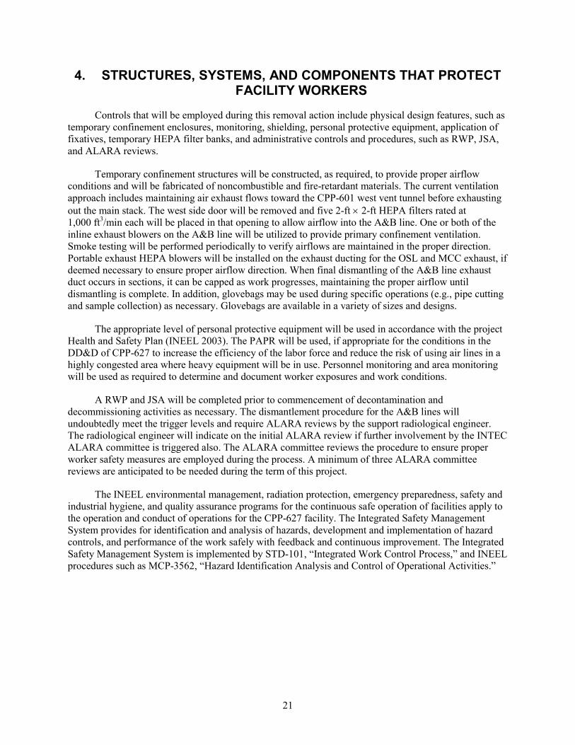
Controls that will be employed during this removal action include physical design features, such as temporary confinement enclosures, monitoring, shielding, personal protective equipment, application of fixatives, temporary HEPA filter banks, and administrative controls and procedures, such as RWP, JSA, and ALARA reviews.
Temporary confinement structures will be constructed, as required, to provide proper airflow conditions and will be fabricated of noncombustible and fire-retardant materials. The current ventilation approach includes maintaining air exhaust flows toward the CPP-601 west vent tunnel before exhausting out the main stack. The west side door will be removed and five 2-ft × 2-ft HEPA filters rated at 1,000 ft3/min each will be placed in that opening to allow airflow into the A&B line. One or both of the inline exhaust blowers on the A&B line will be utilized to provide primary confinement ventilation. Smoke testing will be performed periodically to verify airflows are maintained in the proper direction. Portable exhaust HEPA blowers will be installed on the exhaust ducting for the OSL and MCC exhaust, if deemed necessary to ensure proper airflow direction. When final dismantling of the A&B line exhaust duct occurs in sections, it can be capped as work progresses, maintaining the proper airflow until dismantling is complete. In addition, glovebags may be used during specific operations (e.g., pipe cutting and sample collection) as necessary. Glovebags are available in a variety of sizes and designs.
The appropriate level of personal protective equipment will be used in accordance with the project Health and Safety Plan (INEEL 2003). The PAPR will be used, if appropriate for the conditions in the DD&D of CPP-627 to increase the efficiency of the labor force and reduce the risk of using air lines in a highly congested area where heavy equipment will be in use. Personnel monitoring and area monitoring will be used as required to determine and document worker exposures and work conditions.
A RWP and JSA will be completed prior to commencement of decontamination and decommissioning activities as necessary. The dismantlement procedure for the A&B lines will undoubtedly meet the trigger levels and require ALARA reviews by the support radiological engineer. The radiological engineer will indicate on the initial ALARA review if further involvement by the INTEC ALARA committee is triggered also. The ALARA committee reviews the procedure to ensure proper worker safety measures are employed during the process. A minimum of three ALARA committee reviews are anticipated to be needed during the term of this project.
The INEEL environmental management, radiation protection, emergency preparedness, safety and industrial hygiene, and quality assurance programs for the continuous safe operation of facilities apply to the operation and conduct of operations for the CPP-627 facility. The Integrated Safety Management System provides for identification and analysis of hazards, development and implementation of hazard controls, and performance of the work safely with feedback and continuous improvement. The Integrated Safety Management System is implemented by STD-101, “Integrated Work Control Process,” and INEEL procedures such as MCP-3562, “Hazard Identification Analysis and Control of Operational Activities.”

22
5. SAFETY AND HEALTH MANAGEMENT CONTROLS
5.1 Health and Safety Program
The removal action activities will be performed in a manner that ensures the health and safety of workers and the public and the protection of the environment. Measures will also be taken to minimize the possibility of releases to the environment.
5.1.1 Site-Specific Health and Safety Plan and Activity Hazard Analysis
The Health and Safety Plan for Deactivation, Decontamination, and Decommissioning Projects with CERCLA, RCRA Closure, and VCO Activities (INEEL 2003) is the site-specific plan governing the work under this removal action. Additionally, a Health and Safety Plan supplement will be completed and included with each project work order submitted. The supplement identifies personnel and individual responsibilities with work scope and other project-specific details. The building access and work activities are controlled by approved work packages. A RWP will be prepared for work in areas with potential radiological hazards. The personnel assigned to the project and work site visitors must strictly adhere to the Health and Safety Plan and RWP provisions.

23
6. ENVIRONMENTAL MANAGEMENT AND CONTROLS
6.1 Applicable or Relevant and Appropriate Requirements
The CPP-627 non-time critical removal action will comply with the substantive applicable or relevant and appropriate requirements (ARARs). Table 1 lists the ARARs for this removal action. These ARARs are a compilation and expansion of the ARARs identified in the OU 3-13 ROD. The ARARs list is based on the following operations:
• Management of CERCLA wastes will be subject to meeting the Waste Acceptance Criteria (WAC) of the receiving facility, whether that facility is an on-INEEL facility, such as the ICDF, Radioactive Waste Management Complex, Landfill Complex at the Central Facilities Area (CFA), or an off-INEEL facility. The ICDF is the preferred location for disposal of contaminated CERCLA wastes and is located within the WAG 3 area of contamination (AOC) (DOE-ID 1999).
• CERCLA wastes that will be generated during implementation of the removal action will be handled in accordance with the ARARs identified in Table 1.
• Waste such as piping that would be generated by removal of portions of a HWMA/RCRA-regulated system at CPP-627 will be managed, as necessary, at an on-INEEL HWMA/RCRA-compliant storage facility and disposed of at an off-INEEL RCRA-compliant TSDF.
• As the wastes will be CERCLA wastes generated within the WAG 3 AOC, land disposal restrictions are not applicable unless placement is triggered or treatment is performed, except as otherwise noted within this document.
• Though not expected to be encountered, waste generated during the CPP-627 removal action that has uncertainties associated with waste classification (i.e., whether the waste may be high-level waste), such waste will be appropriately staged/stored until appropriate waste classification determinations are made under appropriate criteria.
• If decontamination liquids are generated, they may be transferred, using the existing waste lines when possible, to the CPP-601 WG/WH Cells storage and treatment tanks. These tanks are HWMA/RCRA-regulated, and any wastes sent to these tanks would be required to meet the PEW WAC prior to transfer.
• Debris generated during demolition of CPP-627 may have paint that has polychlorinated biphenyls (PCBs). If encountered, such wastes may trigger substantive requirements of the Toxic Substance Control Act. Lead-contaminated paint may be generated during demolition, which will be subject to the substantive requirements of RCRA hazardous waste regulations. These wastes are planned for disposal at the ICDF, unless demonstrated that the wastes are eligible for disposal as solid waste at the Landfill Complex at the CFA.

24
Tabl
e 1.
Sum
mar
y of
app
licab
le o
r rel
evan
t and
app
ropr
iate
requ
irem
ents
for t
he C
PP-6
27 n
on-ti
me
criti
cal r
emov
al a
ctio
n.
Req
uire
men
t (C
itatio
n)
Des
crip
tion
Com
plia
nce
Stra
tegy
C
lean
Air
Act
and
Idah
o A
ir R
egul
atio
ns
“Tox
ic S
ubst
ance
s,” ID
APA
58.
01.0
1.16
1
App
lies t
o th
e bu
ildin
g de
mol
ition
and
was
te h
andl
ing
activ
ities
.
The
air p
erm
ittin
g ap
plic
abili
ty
dete
rmin
atio
n pr
epar
ed fo
r thi
s pro
ject
de
term
ined
that
no
toxi
c ai
r pol
luta
nts
are
expe
cted
to b
e pr
esen
t (Fo
rm 4
50.3
0,
2004
). “N
atio
nal E
mis
sion
Sta
ndar
ds fo
r Haz
ardo
us A
ir Po
lluta
nts,”
<10
mre
m/y
r 40
CFR
61.
92, “
Stan
dard
” 40
CFR
61.
93, “
Emis
sion
Mon
itorin
g an
d Te
st P
roce
dure
s”
40 C
FR 6
1.94
(a),
“Com
plia
nce
and
Rep
ortin
g”
App
lies t
o th
e bu
ildin
g de
mol
ition
and
was
te h
andl
ing
activ
ities
.
An
eval
uatio
n to
det
erm
ine
the
exte
nt o
f ra
diol
ogic
al e
mis
sion
s has
bee
n pe
rfor
med
. Th
is e
valu
atio
n id
entif
ied
that
the
pote
ntia
l un
abat
ed ra
diol
ogic
al e
mis
sion
s fro
m th
is
sour
ce fo
r pur
pose
s of c
ontin
uous
m
onito
ring
appl
icab
ility
was
cal
cula
ted
at 1
.30
E-06
mre
m/y
r, w
hich
is b
elow
th
e 0.
1 m
rem
/yr s
tand
ard.
Sou
rces
with
un
miti
gate
d po
tent
ial e
mis
sion
s det
erm
ined
to
equ
al o
r exc
eed
0.1
mre
m/y
r are
re
quire
d to
be
cont
inuo
usly
mon
itore
d. T
he
pote
ntia
l aba
ted
radi
olog
ical
em
issi
ons
wer
e ca
lcul
ated
at 1
.3E-
08. T
he a
ctiv
ities
w
ill b
e as
sess
ed th
roug
hout
the
proj
ect t
o en
sure
that
ther
e ar
e no
cha
nges
in
oper
atio
nal m
easu
res t
hat w
ould
incr
ease
po
tent
ial e
mis
sion
s. In
add
ition
, to
cont
rol
pote
ntia
l rad
ionu
clid
e em
issi
ons,
cont
rols
w
ill b
e us
ed, i
nclu
ding
the
use
of sp
rays
, fix
ativ
es, f
ilter
s, co
ntro
l ten
ts, o
r oth
er
emis
sion
-lim
iting
feat
ures
. The
ra
diol
ogic
al e
mis
sion
s inf
orm
atio
n w
ill b
e pr
ovid
ed fo
r the
INEE
L N
atio
nal E
mis
sion
St
anda
rd fo
r Haz
ardo
us A
ir Po
lluta
nts
annu
al re
port.
“N
atio
nal E
mis
sion
Sta
ndar
ds fo
r Haz
ardo
us A
ir Po
lluta
nts,”
40
CFR
61.
145,
“St
anda
rds f
or D
emol
ition
and
Ren
ovat
ion”
A
pplie
s to
asbe
stos
-con
tain
ing
mat
eria
ls e
ncou
nter
ed d
urin
g de
mol
ition
.
The
subs
tant
ive
requ
irem
ents
ass
ocia
ted
with
asb
esto
s rem
oval
and
dem
oliti
on
activ
ities
and
trai
ning
of p
erso
nnel
will
be
follo
wed
.

Tabl
e 1.
(con
tinue
d).
25
Req
uire
men
t (C
itatio
n)
Des
crip
tion
Com
plia
nce
Stra
tegy
“R
ules
for C
ontro
l of F
ugiti
ve D
ust,”
and
“G
ener
al R
ules
” (I
DA
PA 5
8.01
.01.
650
and
.651
) A
pplie
s to
the
build
ing
dem
oliti
on a
nd w
aste
han
dlin
g ac
tiviti
es.
Mea
sure
s will
be
impl
emen
ted
durin
g th
e re
mov
al a
ctio
n to
min
imiz
e th
e ge
nera
tion
of fu
gitiv
e du
st. T
hese
mea
sure
s may
in
clud
e w
ater
spra
ys, c
omm
erci
al d
ust
supp
ress
ants
, min
imiz
ing
vehi
cle
spee
ds,
and
wor
k co
ntro
ls d
urin
g hi
gh w
inds
. R
CR
A a
nd Id
aho
Haz
ardo
us W
aste
Man
agem
ent A
ct
Gen
erat
or S
tand
ards
:
“H
azar
dous
Was
te D
eter
min
atio
n,”
40 C
FR 2
62.1
1 (I
DA
PA 5
8.01
.05.
006)
A
pplie
s to
was
te th
at w
ill b
e ge
nera
ted
durin
g th
e re
mov
al
actio
n an
d di
spos
ed o
f out
side
th
e W
AG
3 A
OC
.
Haz
ardo
us w
aste
det
erm
inat
ions
will
be
perf
orm
ed o
n w
aste
stre
ams g
ener
ated
du
ring
the
rem
oval
act
ion
and
disp
osed
of
outs
ide
the
AO
C, a
s spe
cifie
d in
DO
E-ID
(2
004d
). G
ener
al F
acili
ty S
tand
ards
:
“T
empo
rary
Uni
ts,”
40
CFR
264
.553
(ID
APA
58.
01.0
5.00
8)
Was
tes m
ay b
e tre
ated
or
tem
pora
rily
stor
ed in
a te
mpo
rary
un
it pr
ior t
o di
spos
al.
The
sitin
g of
a te
mpo
rary
uni
t to
man
age
was
tes i
s not
pla
nned
due
to th
e av
aila
bilit
y of
the
Stag
ing
and
Stor
age
Ann
ex (S
SA)
and
ICD
F fo
r man
agem
ent o
f pot
entia
l w
aste
stre
ams r
equi
ring
stor
age.
If, d
ue to
un
usua
l circ
umst
ance
s, a
tem
pora
ry u
nit i
s ne
eded
, the
site
and
loca
tion
will
be
prov
ided
to th
e A
genc
ies w
ith a
5-d
ay
com
men
t per
iod.
“R
emed
iatio
n W
aste
Sta
ging
Pile
s,” 4
0 C
FR 2
64.5
54
(ID
APA
58.
01.0
5.00
8)
Was
tes m
ay b
e te
mpo
raril
y st
aged
prio
r to
disp
osal
with
out
trigg
erin
g la
nd d
ispo
sal
rest
rictio
ns.
The
use
of st
agin
g pi
les a
t the
site
is n
ot
antic
ipat
ed d
ue to
ava
ilabi
lity
of th
e SS
A
and
ICD
F fo
r man
agem
ent o
f was
te
stre
ams r
equi
ring
stag
ing.
If, d
ue to
m
anag
emen
t nee
ds, a
was
te st
agin
g pi
le is
ne
cess
ary,
it w
ill b
e es
tabl
ishe
d in
pr
oxim
ity to
the
site
and
the
loca
tion
will
be
pro
vide
d to
the
Age
ncie
s with
a 5
-day
co
mm
ent p
erio
d.
Tabl
e 1.
(con
tinue
d).
26
Req
uire
men
t (C
itatio
n)
Des
crip
tion
Com
plia
nce
Stra
tegy
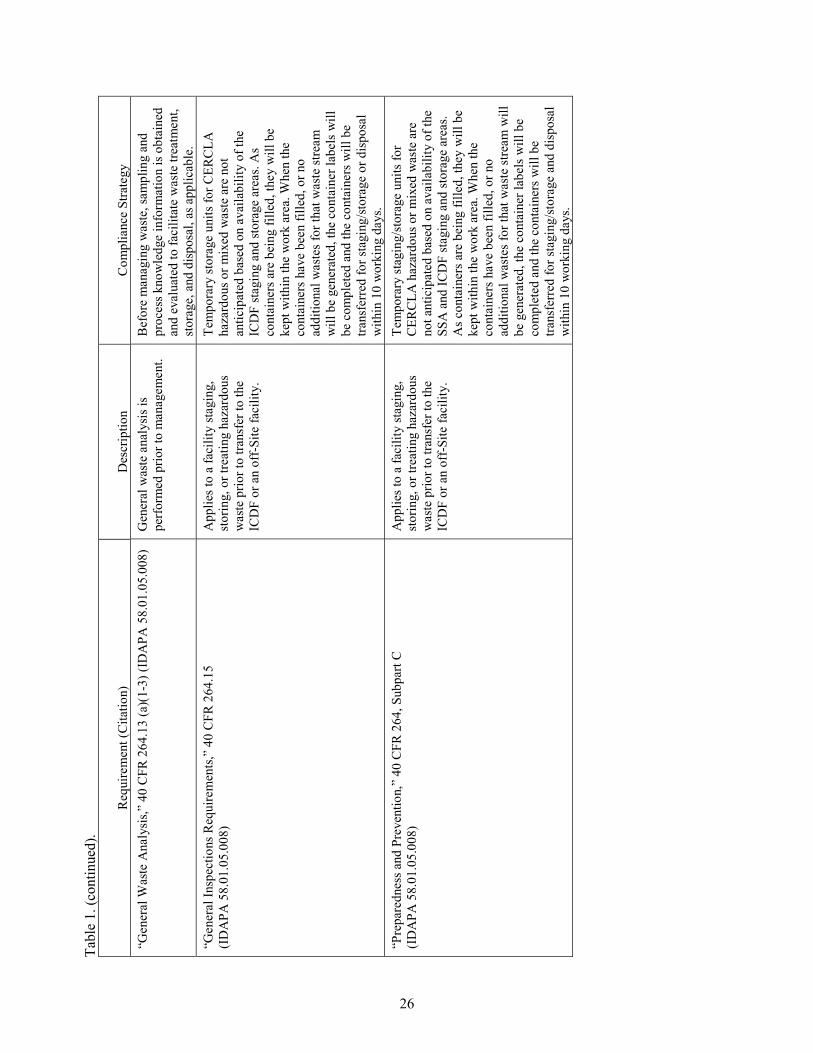
“G
ener
al W
aste
Ana
lysi
s,” 4
0 C
FR 2
64.1
3 (a
)(1-
3) (I
DA
PA 5
8.01
.05.
008)
G
ener
al w
aste
ana
lysi
s is
perf
orm
ed p
rior t
o m
anag
emen
t. B
efor
e m
anag
ing
was
te, s
ampl
ing
and
proc
ess k
now
ledg
e in
form
atio
n is
obt
aine
d an
d ev
alua
ted
to fa
cilit
ate
was
te tr
eatm
ent,
stor
age,
and
dis
posa
l, as
app
licab
le.
“Gen
eral
Insp
ectio
ns R
equi
rem
ents
,” 4
0 C
FR 2
64.1
5 (I
DA
PA 5
8.01
.05.
008)
A
pplie
s to
a fa
cilit
y st
agin
g,
stor
ing,
or t
reat
ing
haza
rdou
s w
aste
prio
r to
trans
fer t
o th
e IC
DF
or a
n of
f-Si
te fa
cilit
y.
Tem
pora
ry st
orag
e un
its fo
r CER
CLA
ha
zard
ous o
r mix
ed w
aste
are
not
an
ticip
ated
bas
ed o
n av
aila
bilit
y of
the
ICD
F st
agin
g an
d st
orag
e ar
eas.
As
cont
aine
rs a
re b
eing
fille
d, th
ey w
ill b
e ke
pt w
ithin
the
wor
k ar
ea. W
hen
the
cont
aine
rs h
ave
been
fille
d, o
r no
addi
tiona
l was
tes f
or th
at w
aste
stre
am
will
be
gene
rate
d, th
e co
ntai
ner l
abel
s will
be
com
plet
ed a
nd th
e co
ntai
ners
will
be
trans
ferr
ed fo
r sta
ging
/sto
rage
or d
ispo
sal
with
in 1
0 w
orki
ng d
ays.
“Pre
pare
dnes
s and
Pre
vent
ion,
” 40
CFR
264
, Sub
part
C
(ID
APA
58.
01.0
5.00
8)
App
lies t
o a
faci
lity
stag
ing,
st
orin
g, o
r tre
atin
g ha
zard
ous
was
te p
rior t
o tra
nsfe
r to
the
ICD
F or
an
off-
Site
faci
lity.
Tem
pora
ry st
agin
g/st
orag
e un
its fo
r C
ERC
LA h
azar
dous
or m
ixed
was
te a
re
not a
ntic
ipat
ed b
ased
on
avai
labi
lity
of th
e SS
A a
nd IC
DF
stag
ing
and
stor
age
area
s. A
s con
tain
ers a
re b
eing
fille
d, th
ey w
ill b
e ke
pt w
ithin
the
wor
k ar
ea. W
hen
the
cont
aine
rs h
ave
been
fille
d, o
r no
addi
tiona
l was
tes f
or th
at w
aste
stre
am w
ill
be g
ener
ated
, the
con
tain
er la
bels
will
be
com
plet
ed a
nd th
e co
ntai
ners
will
be
trans
ferr
ed fo
r sta
ging
/sto
rage
and
dis
posa
l w
ithin
10
wor
king
day
s.
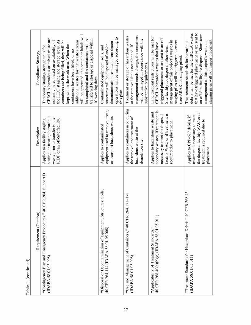
Tabl
e 1.
(con
tinue
d).
27
Req
uire
men
t (C
itatio
n)
Des
crip
tion
Com
plia
nce
Stra
tegy
“C
ontin
genc
y Pl
an a
nd E
mer
genc
y Pr
oced
ures
,” 4
0 C
FR 2
64, S
ubpa
rt D
(I
DA
PA 5
8.01
.05.
008)
A
pplie
s to
a fa
cilit
y st
agin
g,
stor
ing,
or t
reat
ing
haza
rdou
s w
aste
prio
r to
trans
fer t
o th
e IC
DF
or a
n of
f-Si
te fa
cilit
y.
Tem
pora
ry st
agin
g/st
orag
e un
its fo
r C
ERC
LA h
azar
dous
or m
ixed
was
te a
re
not a
ntic
ipat
ed b
ased
on
avai
labi
lity
of
the
ICD
F st
agin
g an
d st
orag
e ar
eas.
As
cont
aine
rs a
re b
eing
fille
d, th
ey w
ill b
e ke
pt w
ithin
the
wor
k ar
ea. W
hen
the
cont
aine
rs h
ave
been
fille
d, o
r no
addi
tiona
l was
tes f
or th
at w
aste
stre
am
will
be
gene
rate
d, th
e co
ntai
ner l
abel
s will
be
com
plet
ed a
nd th
e co
ntai
ners
will
be
trans
ferr
ed to
stor
age
or d
ispo
sal w
ithin
10
wor
king
day
s. “D
ispo
sal o
r Dec
onta
min
atio
n of
Equ
ipm
ent,
Stru
ctur
es, S
oils
,”
40 C
FR 2
64.1
14 (I
DA
PA 5
8.01
.05.
008)
A
pplie
s to
cont
amin
ated
eq
uipm
ent u
sed
to re
mov
e, tr
eat,
or tr
ansp
ort h
azar
dous
was
te.
Con
tam
inat
ed e
quip
men
t, so
ils, a
nd
stru
ctur
es w
ill b
e di
spos
ed o
f and
/or
deco
ntam
inat
ion
resi
dual
s fro
m d
econ
op
erat
ions
will
be
man
aged
acc
ordi
ng to
th
is p
lan.
“U
se a
nd M
anag
emen
t of C
onta
iner
s,” 4
0 C
FR 2
64.1
71–1
78
(ID
APA
58.
01.0
5.00
8)
App
lies t
o co
ntai
ners
use
d du
ring
the
rem
oval
and
trea
tmen
t of
haza
rdou
s was
te a
t the
de
mol
ition
site
.
Trea
tmen
t or s
tora
ge o
f haz
ardo
us w
aste
s at
the
rem
oval
site
is n
ot p
lann
ed. I
f m
anag
emen
t nee
ds c
hang
e, th
e co
ntai
ners
w
ill b
e m
anag
ed in
acc
orda
nce
with
the
subs
tant
ive
requ
irem
ents
. “A
pplic
abili
ty o
f Tre
atm
ent S
tand
ards
,”
40 C
FR 2
68.4
0(a)
(b)(
e) (I
DA
PA 5
8.01
.05.
011)
A
pplie
s to
haza
rdou
s was
te a
nd
seco
ndar
y w
aste
s, if
treat
men
t is
nece
ssar
y to
mee
t the
dis
posa
l fa
cilit
y W
AC
or i
f tre
atm
ent i
s re
quire
d du
e to
pla
cem
ent.
Land
dis
posa
l res
trict
ions
will
be
met
for
CER
CLA
haz
ardo
us w
aste
s tha
t hav
e tri
gger
ed p
lace
men
t or a
re se
nt to
an
off-
Site
faci
lity
for d
ispo
sal.
Shor
t-ter
m
man
agem
ent o
f thi
s pro
ject
’s w
aste
s in
stag
ing
pile
s will
not
trig
ger p
lace
men
t (s
ee A
RA
R fo
r sta
ging
pile
s).
“Tre
atm
ent S
tand
ards
for H
azar
dous
Deb
ris,”
40
CFR
268
.45
(ID
APA
58.
01.0
5.01
1)
App
lies t
o C
PP-6
27 d
ebris
, if
treat
men
t is n
eces
sary
to m
eet
the
disp
osal
faci
lity
WA
C o
r if
treat
men
t is r
equi
red
due
to
plac
emen
t.
The
treat
men
t sta
ndar
ds fo
r haz
ardo
us
debr
is w
ill b
e m
et fo
r the
CER
CLA
was
tes
that
hav
e tri
gger
ed p
lace
men
t or a
re se
nt to
an
off
-Site
faci
lity
for d
ispo
sal.
Shor
t-ter
m
man
agem
ent o
f thi
s pro
ject
’s w
aste
in
stag
ing
pile
s will
not
trig
ger p
lace
men
t.

Tabl
e 1.
(con
tinue
d).
28
Req
uire
men
t (C
itatio
n)
Des
crip
tion
Com
plia
nce
Stra
tegy
“U
nive
rsal
Tre
atm
ent S
tand
ards
,” 4
0 C
FR 2
68.4
8(a)
(I
DA
PA 5
8.01
.05.
011)
A
pplie
s to
nond
ebris
haz
ardo
us
was
te a
nd se
cond
ary
was
tes,
if tre
atm
ent i
s nec
essa
ry to
mee
t th
e di
spos
al fa
cilit
y W
AC
or i
f tre
atm
ent i
s req
uire
d du
e to
pl
acem
ent.
The
treat
men
t sta
ndar
ds fo
r haz
ardo
us
debr
is w
ill b
e m
et fo
r the
CER
CLA
was
tes
that
hav
e tri
gger
ed p
lace
men
t or a
re se
nt to
an
off
-Site
faci
lity
for d
ispo
sal.
Shor
t-ter
m
man
agem
ent o
f thi
s pro
ject
’s w
aste
in
stag
ing
pile
s will
not
trig
ger p
lace
men
t. “A
ltern
ativ
e LD
R T
reat
men
t Sta
ndar
ds fo
r Con
tam
inat
ed S
oil,”
40
CFR
268
.49
(ID
APA
58.
01.0
5.01
1)
App
lies t
o co
ntam
inat
ed so
il, if
tre
atm
ent i
s nec
essa
ry to
mee
t th
e di
spos
al fa
cilit
y W
AC
or i
f tre
atm
ent i
s req
uire
d du
e to
pl
acem
ent.
The
alte
rnat
ive
treat
men
t sta
ndar
ds fo
r co
ntam
inat
ed so
ils w
ill b
e m
et if
pla
cem
ent
is tr
igge
red
or w
aste
s are
sent
to a
n of
f-Si
te
faci
lity
for d
ispo
sal.
“PC
B D
econ
tam
inat
ion
Stan
dard
s and
Pro
cedu
res:
D
econ
tam
inat
ion
Stan
dard
s,” 4
0 C
FR 7
61.7
9(b)
(1)
App
licab
le to
dec
onta
min
atio
n of
equ
ipm
ent w
ith P
CB
co
ntam
inat
ion,
if P
CB
was
tes
are
gene
rate
d.
Thes
e st
anda
rds w
ill b
e m
et fo
r wat
er
cont
aini
ng P
CB
s whe
n de
cont
amin
atio
n ef
forts
are
impl
emen
ted.
“Dec
onta
min
atio
n St
anda
rds a
nd P
roce
dure
s: S
elf-I
mpl
emen
ting
Dec
onta
min
atio
n Pr
oced
ures
,” 4
0 C
FR 7
61.7
9(c)
(1) a
nd (2
) A
pplic
able
to d
econ
tam
inat
ion
of e
quip
men
t with
PC
B
cont
amin
atio
n, if
PC
B w
aste
s ar
e ge
nera
ted.
This
stan
dard
will
be
impl
emen
ted
durin
g de
cont
amin
atio
n of
equ
ipm
ent a
nd
mat
eria
ls.
“Dec
onta
min
atio
n So
lven
ts,”
40
CFR
761
.79(
d)
App
licab
le to
dec
onta
min
atio
n of
equ
ipm
ent u
sed
to m
anag
e PC
B-c
onta
min
ated
was
te, i
f PC
B w
aste
s are
gen
erat
ed.
Solv
ents
will
be
used
, as n
eces
sary
, to
rem
ove
PCB
con
tam
inat
ion
from
eq
uipm
ent a
nd m
ater
ials
. Use
and
m
anag
emen
t of s
olve
nts w
ill b
e in
ac
cord
ance
with
this
requ
irem
ent.
“Lim
itatio
n of
Exp
osur
e an
d C
ontro
l of R
elea
ses,”
40
CFR
761
.79(
e)
App
licab
le to
dec
onta
min
atio
n ac
tiviti
es o
f equ
ipm
ent w
ith
PCB
-con
tam
inat
ed w
aste
, if
deco
ntam
inat
ion
is p
erfo
rmed
.
This
stan
dard
will
be
used
to li
mit
expo
sure
and
rele
ases
ass
ocia
ted
with
de
cont
amin
atio
n ac
tiviti
es. C
ontro
ls w
ill
incl
ude
use
of p
rote
ctiv
e cl
othi
ng a
nd
equi
pmen
t for
per
sonn
el a
nd o
ther
m
easu
res t
o pr
otec
t aga
inst
rele
ases
of
PC
Bs.
“Dec
onta
min
atio
n W
aste
and
Res
idue
s,” 4
0 C
FR 7
61.7
9(g)
A
pplic
able
to m
anag
emen
t of
deco
ntam
inat
ed w
aste
s and
re
sidu
als f
rom
PC
B-
cont
amin
ated
equ
ipm
ent,
if PC
B w
aste
s are
gen
erat
ed.
Whe
re P
CB
was
te is
exp
ecte
d, w
aste
st
ream
sam
plin
g an
d an
alys
is w
ill b
e pe
rfor
med
to c
ompl
ete
the
was
te p
rofil
es
for t
he d
ispo
sal f
acili
ty.

Tabl
e 1.
(con
tinue
d).
29
Req
uire
men
t (C
itatio
n)
Des
crip
tion
Com
plia
nce
Stra
tegy
To
-Be-
Con
side
red
Req
uire
men
ts
“Rad
iatio
n Pr
otec
tion
of th
e Pu
blic
and
the
Envi
ronm
ent,”
D
OE
Ord
er 5
400.
5, C
hapt
er II
(1)(
a,b)
A
pplie
s to
the
CPP
-627
bui
ldin
g be
fore
, dur
ing,
and
afte
r the
re
mov
al a
ctio
n. S
ubst
antiv
e de
sign
and
con
stru
ctio
n re
quire
men
ts w
ill b
e m
et to
kee
p pu
blic
exp
osur
es A
LAR
A.
Spec
ific
radi
atio
n do
se li
mits
to th
e pu
blic
will
be
met
thro
ugh
mon
itorin
g,
adm
inis
trativ
e, a
nd e
ngin
eerin
g co
ntro
ls
as re
quire
d du
ring
cons
truct
ion
in
cont
amin
ated
are
as.
“Rad
ioac
tive
Was
te M
anag
emen
t,” D
OE
Ord
er 4
35.1
A
pplie
s to
the
CPP
-627
bui
ldin
g be
fore
, dur
ing,
and
afte
r the
re
mov
al a
ctio
n. S
ubst
antiv
e de
sign
and
con
stru
ctio
n re
quire
men
ts w
ill b
e m
et to
pr
otec
t wor
kers
.
Dos
e to
wor
kers
will
be
redu
ced
thro
ugh
the
use
of m
onito
ring,
adm
inis
trativ
e, a
nd
engi
neer
ing
cont
rols
. JSA
s and
/or R
WPs
w
ill b
e pr
epar
ed fo
r tas
ks in
whi
ch th
ere
is
the
pote
ntia
l for
exp
osur
es to
radi
oact
ive
cont
amin
atio
n/m
ater
ials
. RW
Ps w
ill b
e de
velo
ped
by ra
diol
ogic
al c
ontro
l pe
rson
nel b
ased
on
actu
al h
azar
ds a
nd in
ac
cord
ance
with
app
licab
le IN
EEL
man
uals
. Ini
tial A
LAR
A re
view
s w
ill b
e co
nduc
ted
and
forw
arde
d to
the
INTE
C/P
ower
Bur
st F
acili
ty S
ite A
LAR
A
Com
mitt
ee w
hen
radi
olog
ical
trig
ger l
evel
s ar
e m
et w
hich
requ
ire fu
rther
revi
ew a
nd
engi
neer
con
trols
to m
itiga
te p
erso
nnel
ex
posu
re.
EPA
Reg
ion
10 F
inal
Pol
icy
on In
stitu
tiona
l Con
trols
at F
eder
al F
acili
ties
App
lies i
f con
tam
inat
ion
is le
ft in
pl
ace
afte
r rem
oval
of t
he
CPP
-627
bui
ldin
g.
Und
er th
is re
mov
al a
ctio
n, th
e bu
ildin
g st
ruct
ure
and
com
pone
nts w
ill b
e re
mov
ed
and
disp
osed
of.
Con
trols
will
be
impl
emen
ted
(e.g
., en
gine
ered
cov
er) t
o pu
t the
site
in a
stab
le c
ondi
tion
that
wou
ld
prec
lude
infil
tratio
n of
wat
er a
nd m
igra
tion
of th
e co
ntam
inan
ts b
elow
the
conc
rete
sl
ab to
the
aqui
fer.
“Off
-Site
Rul
e,”
40 C
FR 3
00.4
40
App
lies i
f was
tes a
re sh
ippe
d of
f-Si
te fo
r sto
rage
, tre
atm
ent,
or
disp
osal
.
Any
off
-Site
faci
lity
rece
ivin
g C
ERC
LA
was
tes w
ill b
e su
bjec
t to
com
plia
nce
with
40
CFR
300
.440
requ
irem
ents
. Prio
r to
ship
men
t of a
ny C
ERC
LA re
med
iatio
n w
aste
s to
an o
ff-S
ite fa
cilit
y, a
suita
bilit
y de
term
inat
ion
will
be
perf
orm
ed a
nd
docu
men
ted.
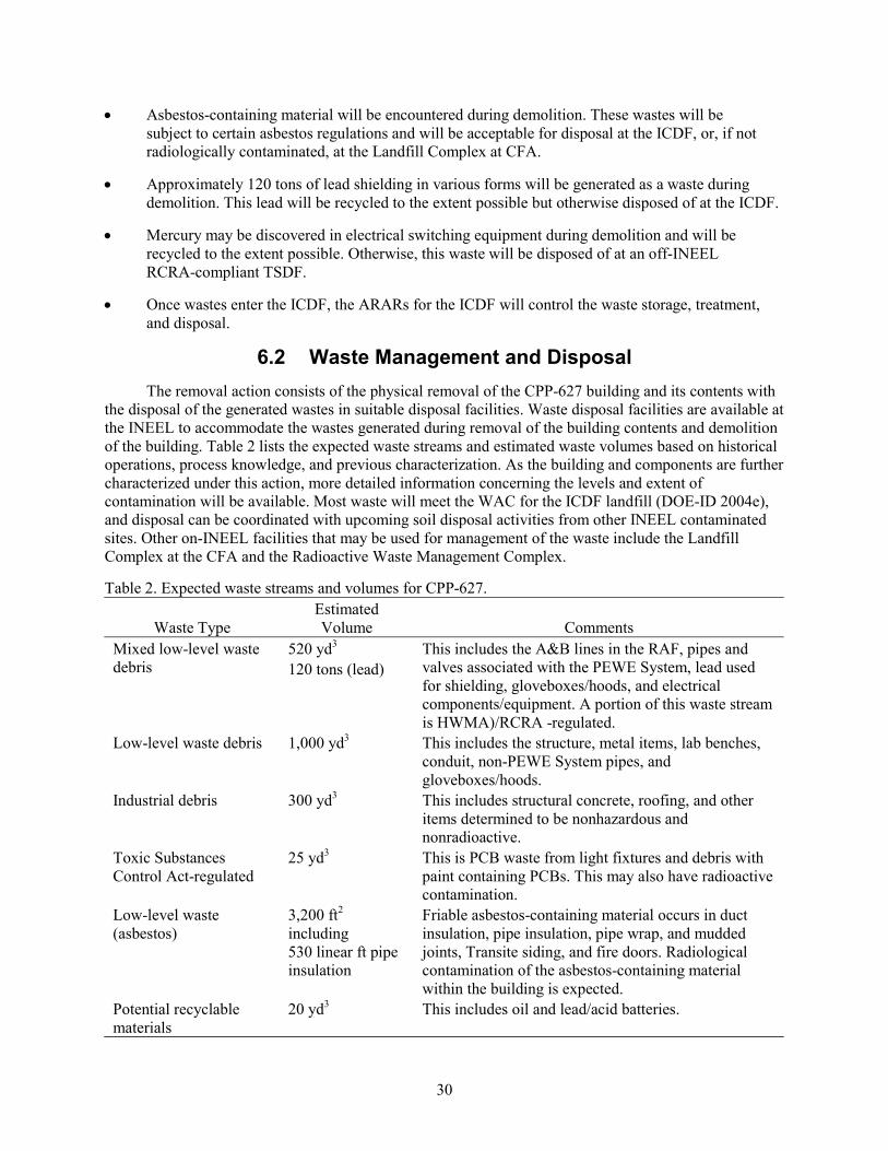
30
• Asbestos-containing material will be encountered during demolition. These wastes will be subject to certain asbestos regulations and will be acceptable for disposal at the ICDF, or, if not radiologically contaminated, at the Landfill Complex at CFA.
• Approximately 120 tons of lead shielding in various forms will be generated as a waste during demolition. This lead will be recycled to the extent possible but otherwise disposed of at the ICDF.
• Mercury may be discovered in electrical switching equipment during demolition and will be recycled to the extent possible. Otherwise, this waste will be disposed of at an off-INEEL RCRA-compliant TSDF.
• Once wastes enter the ICDF, the ARARs for the ICDF will control the waste storage, treatment, and disposal.
6.2 Waste Management and Disposal The removal action consists of the physical removal of the CPP-627 building and its contents with
the disposal of the generated wastes in suitable disposal facilities. Waste disposal facilities are available at the INEEL to accommodate the wastes generated during removal of the building contents and demolition of the building. Table 2 lists the expected waste streams and estimated waste volumes based on historical operations, process knowledge, and previous characterization. As the building and components are further characterized under this action, more detailed information concerning the levels and extent of contamination will be available. Most waste will meet the WAC for the ICDF landfill (DOE-ID 2004e), and disposal can be coordinated with upcoming soil disposal activities from other INEEL contaminated sites. Other on-INEEL facilities that may be used for management of the waste include the Landfill Complex at the CFA and the Radioactive Waste Management Complex.
Table 2. Expected waste streams and volumes for CPP-627.
Waste Type Estimated Volume Comments
Mixed low-level waste debris
520 yd3
120 tons (lead) This includes the A&B lines in the RAF, pipes and valves associated with the PEWE System, lead used for shielding, gloveboxes/hoods, and electrical components/equipment. A portion of this waste stream is HWMA)/RCRA -regulated.
Low-level waste debris 1,000 yd3 This includes the structure, metal items, lab benches, conduit, non-PEWE System pipes, and gloveboxes/hoods.
Industrial debris 300 yd3 This includes structural concrete, roofing, and other items determined to be nonhazardous and nonradioactive.
Toxic Substances Control Act-regulated
25 yd3 This is PCB waste from light fixtures and debris with paint containing PCBs. This may also have radioactive contamination.
Low-level waste (asbestos)
3,200 ft2
including 530 linear ft pipe insulation
Friable asbestos-containing material occurs in duct insulation, pipe insulation, pipe wrap, and mudded joints, Transite siding, and fire doors. Radiological contamination of the asbestos-containing material within the building is expected.
Potential recyclable materials
20 yd3 This includes oil and lead/acid batteries.

31
HWMA/RCRA-regulated systems that are a hazardous waste will be managed in a RCRA-compliant TSDF. Wastes not complying with the ICDF WAC will be staged/stored for disposal at an on-INEEL or off-INEEL facility, subject to meeting the facility’s WAC. Building materials or contents will be recycled to the extent possible. More details regarding how wastes will be handled to meet the ARARs are given in the Waste Management Plan (DOE-ID 2004d). Finalization of the Action Memorandum is the authorization necessary to begin the CERCLA-compliant removal action.
6.3 Natural and Cultural Resource Protection
The location of the INEEL offers long-distance views of the INEEL’s rolling hills, buttes, and volcanic outcrops and of the Lemhi, Lost River, and Bitterroot mountain ranges that border the INEEL on the north and west. The INTEC is located on a relatively flat area surrounded by undeveloped land that supports shrub-steppe grassland vegetation. Other INEEL industrial facilities visible from the INTEC include the CFA, Test Reactor Area, Naval Reactors Facility, and Power Burst Facility. Demolition of this building will not affect the visual resources near the INTEC.
Demolition would proceed only in accordance with the substantive requirements resulting from the consultation between DOE Idaho and the Idaho State Historic Preservation Office.
A Memorandum of Agreement was signed between the State Historic Preservation Office and DOE Idaho in the spring of 1998. The agreement called for completion of a historic American engineering record report within 3 months after the demolition is completed for Buildings CPP-601, -603, -627, -640, and -648.
Archeological sites left by Native American hunter-gatherers dot the landscape surrounding the INTEC and continue to be important to the Shoshone-Bannock Tribes. Historic archaeological sites are also common in the area and are located in proximity to the facility perimeter fence. Over the years, DOE has disturbed the area within the fence by constructing and paving roads and erecting buildings; therefore, little, if any natural habitat or archaeological sites exist within the fence. There are no archaeological sites inside the CPP-627 building, which was built in 1955. Any nests of migratory birds (excluding house sparrows, starlings, and pigeons) found nesting in the facility will be relocated or removed during the non-nesting season.
This removal action would not affect the current land use or the environment outside the footprint of Building CPP-627.
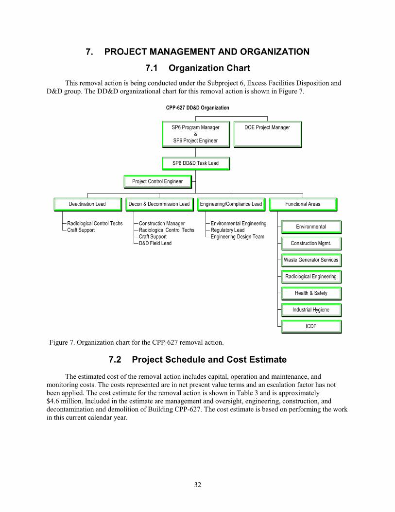
32
7. PROJECT MANAGEMENT AND ORGANIZATION
7.1 Organization Chart This removal action is being conducted under the Subproject 6, Excess Facilities Disposition and
D&D group. The DD&D organizational chart for this removal action is shown in Figure 7.
CPP-627 DD&D Organization
Project Control Engineer
Radiological Control TechsCraft Support
Deactivation Lead
Construction ManagerRadiological Control TechsCraft SupportD&D Field Lead
Decon & Decommission Lead
Environmental EngineeringRegulatory LeadEngineering Design Team
Engineering/Compliance Lead
Environmental
Construction Mgmt.
Waste Generator Services
Radiological Engineering
Health & Safety
Industrial Hygiene
ICDF
Functional Areas
SP6 DD&D Task Lead
SP6 Program Manager&
SP6 Project Engineer
DOE Project Manager
Figure 7. Organization chart for the CPP-627 removal action.
7.2 Project Schedule and Cost Estimate
The estimated cost of the removal action includes capital, operation and maintenance, and monitoring costs. The costs represented are in net present value terms and an escalation factor has not been applied. The cost estimate for the removal action is shown in Table 3 and is approximately $4.6 million. Included in the estimate are management and oversight, engineering, construction, and decontamination and demolition of Building CPP-627. The cost estimate is based on performing the work in this current calendar year.

33
Table 3. Cost estimate for removal action.
Cost Element Removal Action ($)
Management and oversight 407K
Engineering 780K
Construction 152K
Operation and maintenance support —
Surveillance and maintenance —
Decontamination 1,730K
Demolition 1,550K
Subtotal (15-year surveillance and maintenance monitoring period) —
Subtotal (building removal) 4,619K
Total (net present value) 4,619K
Table 4 shows the major activities associated with the removal action. The overall project schedule is shown in Figure 8 and includes the major project tasks from the completion of the sampling plan through completion of the Removal Action Report.
Table 4. Major removal action activities/deliverables schedule.
Removal Action Activities/Deliverables Date
RCRA system identified (drawing) June 24, 2004
Engineering isolation design June 30, 2004
Engineering design for A&B line dismantlement July 8, 2004
Approach for MCC removal August 13, 2004
Engineering design for concrete slab barrier November 11, 2004
7.3 Conduct of Operations
Conduct of operations is imposed to ensure that work is performed in a controlled and organized manner, that all facets of work activities have been considered, and that necessary documentation is maintained.
“Deactivation, Decontamination, and Decommissioning Project Manager’s Handbook” (PLN-1053) and applicable field support instructions and specific work instructions govern the performance of field activities and D&D projects.
Conduct of operations strongly emphasizes technical competency, workplace discipline, and personal accountability to ensure the achievement of a high level of performance during work activities. Project personnel are responsible for fully complying with the handbook. If conflict arises with other instructions or directions, work will be safely stopped until resolution is achieved. Safety is the first priority, and planning will include appropriate safety analysis to identify potential safety and health risks

34
Fi
gure
8. C
PP-6
27 d
econ
tam
inat
ion
and
deco
mm
issi
onin
g pr
ojec
t sch
edul
e.

35
and the means to appropriately mitigate them. Workers will not start work until approved safety procedures, instructions, and directions are provided for nonroutine operations.
Conduct of operations requires workers to be alert and aware of conditions affecting the job site. Operators and workers conducting field activities should be notified of changes in the building and/or work area status, abnormalities, and difficulties encountered in performing project operations. Similarly, operators and workers will notify the chain of command of any unexpected situations.
7.4 Change Management/Configuration Control
If changes arise that result in a fundamental change to the selected response action that is not within the scope of the Action Memorandum and the implementing documents, then a proposed plan and supporting documentation will be prepared to allow DOE, EPA, and DEQ to select a revised response action.
Facility change form(s) will be completed, as necessary, before starting work. Drawings and documents will be changed and approved according to MCP-233. Data files will be established and maintained in accordance with MCP-204, “Administrative Record/Information Repository Procedure.” Reports will be prepared in accordance with MCP-233. When the project is complete, the final status of the facility will be reported to facility management for INEEL status and information requirements. Drawings, if needed, will be prepared in accordance with MCP-2377, “Development, Assessment, and Maintenance of Drawings.”
7.5 Quality Assurance Requirements
The quality program for the Idaho Completion Project is described in applicable INEEL policies and procedures. Applicable INEEL policies and procedures, the Quality Assurance Project Plan for Waste Area Groups 1, 2, 3, 4, 5, 6, 7, 10, and Inactive Sites (DOE-ID 2004f), and this Work Plan govern the functional activities, organizations, and quality assurance/quality control protocols that will be used for this project. Where applicable, the project specifications give the quality assurance/quality control procedures for a given task, consistent with guidance provided in applicable INEEL procedures and the safety category designation.

36
8. PROJECT CLOSEOUT
CPP-627 is attached to a complex of buildings with Group 2 CERCLA sites located beneath the remaining buildings, and contamination may have migrated beneath the CPP-627 concrete floor slab. Following removal of the structure, radiological surveys will be conducted to identify any remaining radioactive contamination. If necessary, controls will be implemented to put the site in a stable condition that would preclude infiltration of water and migration of the contaminants below the slab. Institutional controls such as site access restrictions, warning signs, and periodic inspections of infiltration barriers will be implemented, as necessary. Consistent with the OU 3-13 Group 2, Soils Under Buildings sites, the soil beneath the slab will be evaluated during characterization of the Fuel Reprocessing Complex. If contamination is found, it will be addressed during the end-state planning for the CPP-601 and -640 and adjoining buildings.
After completion of the demolition activities, a Removal Action Report will be prepared. This report will include the following and will follow the guidelines for the “Final Report for Deactivation, Decontamination, and Decommissioning Projects” outlined in the “Deactivation, Decontamination, and Decommissioning Project Manager’s Handbook” (PLN-1053):
• A synopsis of the removal action scope and work performed
• Quantities of waste dispositioned (include total radioactive source term removed)
• Summarization of characterization data
• Discussion of issues encountered during the removal action
• As-built drawings showing final configuration
• Final total costs for the removal action
• Lessons learned.
The report will be forwarded to the records retention center where it will be included with the Administrative Record.

37
9. REFERENCES
10 CFR 830, Subpart B, 2004, “Safety Basis Requirements,” Code of Federal Regulations, Office of the Federal Register, January 2004.
29 CFR 1910.119, 2003, “Process safety management of highly hazardous chemicals,” Code of Federal Regulations, Office of the Federal Register, July 2003.
40 CFR 61.145, 2003, “Standard for demolition and renovation,” Code of Federal Regulations, Office of the Federal Register, July 2003.
40 CFR 61.150, 2003, “Standard for waste disposal for manufacturing, fabricating, demolition, renovation, and spraying operations,” Code of Federal Regulations, Office of the Federal Register, July 2003.
40 CFR 300, 2003, “National Oil and Hazardous Substances Pollution Contingency Plan,” Code of Federal Regulations, Office of the Federal Register, July 2003.
40 CFR 300.415, 2003, “Removal action,” Code of Federal Regulations, Office of the Federal Register, July 2003.
40 CFR 300.440, 2003, “Procedures for planning and implementing off-site response actions,” Code of Federal Regulations, Office of the Federal Register, July 2003.
40 CFR 302.4, Appendix B, 2003, “Radionuclides,” Code of Federal Regulations, Office of the Federal Register, July 2003.
40 CFR 355, 2003, “Emergency planning and notification,” Code of Federal Regulations, Office of the Federal Register, July 2003.
42 USC § 9601 et seq., 1980, “Comprehensive Environmental Response, Compensation and Liability Act of 1980 (CERCLA/Superfund),” United States Code.
DOE-STD-1027-92, Change 1, 1997, “Hazard Categorization and Accident Analysis Techniques for Compliance with DOE Order 5480.23, Nuclear Safety Analysis Reports,” U.S. Department of Energy, September 1997.
DOE-ID, 1999, Final Record of Decision, Idaho Nuclear Technology and Engineering Center, Operable Unit 3-13, DOE/ID-10660, Rev. 0, U.S. Department of Energy, Idaho Operations Office, October 1999.
DOE-ID, 2004a, Engineering Evaluation/Cost Analysis for the Decontamination and Decommissioning of Building CPP-627, the Remote Analytical Facility, DOE/NE-ID-11157, Rev. 1, U.S. Department of Energy, Idaho Operations Office, April 2004.
DOE-ID, 2004b, Action Memorandum for the Decontamination and Decommissioning of Building CPP-627, the Remote Analytical Facility, DOE/NE-ID-11164, Rev. 0, U.S. Department of Energy Idaho Operations Office, June 2004.
DOE-ID, 2004c, CERCLA Characterization of Waste From CPP-627 DD&D, DOE/NE-ID-11163, Rev. 0, U.S. Department of Energy, Idaho Operations Office, April 2004.

38
DOE-ID, 2004d, CPP-627 CERCLA Removal Action Waste Management Plan, DOE/NE-ID-11171, Rev. 0, U.S. Department of Energy, Idaho Operations Office, June 2004.
DOE-ID, 2004e, Waste Acceptance Criteria for ICDF Landfill, DOE/ID-10865, Rev. 6, U.S. Department of Energy, Idaho Operations Office, April 2004.
DOE-ID, 2004f, Quality Assurance Project Plan for Waste Area Groups 1,2,3,4,5,6,7,10, and Inactive Sites, DOE/ID-10587, Rev. 8, U.S. Department of Energy, Idaho Operations Office, March 2004.
DOE ID O 420.C, 2003, “Safety Basis Review and Approval Process,” U.S. Department of Energy, Idaho Operations Office, August 2003.
DOE ID O 420.D, 2003, “Requirements and Guidance for Safety Analysis,” U.S. Department of Energy, Idaho Operations Office, July 2003.
Form 450.30, 2004, “Air Permitting Applicability Determination,” APAD Tracking Number 04-15, prepared for DD&D of CPP-627, Idaho National Engineering and Environmental Laboratory, April 20, 2004.
HAD-177, 2004, “Hazard Assessment Document for the INTEC CPP-627 Facility,” Rev. 0, Idaho National Engineering and Environmental Laboratory, March 5, 2004.
INEEL, 2003, Health and Safety Plan for Deactivation, Decontamination, and Decommissioning Projects with CERCLA, RCRA Closure, or VCO Activities, INEEL/EXT-03-01066, Rev. 0, Idaho National Engineering and Environmental Laboratory, October 2003.
MCP-204, 2003, “CERCLA Administrative Record and Information Repository Procedure of the Idaho Completion Project,” Rev. 7, Idaho National Engineering and Environmental Laboratory, August 14, 2003.
MCP-233, 2002, “Process for Developing, Releasing, and Distributing ER Documents (Supplemental to MCP 135 and MCP-9395),” Rev. 4, Idaho National Engineering and Environmental Laboratory, June 28, 2002.
MCP-2377, 2003, “Development, Assessment, and Maintenance of Drawings,” Rev. 8, Idaho National Engineering and Environmental Laboratory, January 30, 2003.
MCP-3562, 2003, “Hazard Identification Analysis and Control of Operational Activities,” Rev. 8, Idaho National Engineering and Environmental Laboratory, October 1, 2003.
PLN-1053, 2003, “Deactivation, Decontamination, and Decommissioning Project Manager’s Handbook,” Rev. 2, Idaho National Engineering and Environmental Laboratory, November 11, 2003.
STD-101, 2003, “Integrated Work control Process,” Rev. 15, Idaho National Engineering and Environmental Laboratory, July 28, 2003.
Wagner, E. P., 1999, Process Description and Operating History for the CPP-601/-640/-627 Fuel Reprocessing Complex at the Idaho National Engineering and Environmental Laboratory, INEEL/EXT-99-00400, Idaho National Engineering and Environmental Laboratory, June 1999.

39
Appendix A
CPP-627 Removal Action RCRA Regulated Piping

40

41
CPP-627 Removal Action RCRA Regulated Piping
Location Line number Drawing Number Comments
West Bench Sink OSL/RAF
1 1/2”-PE-AR-154073
379453 REV 5 Drains to 2”-PE-AR-154073
East Bench Sink OSL/RAF
1 1/2”-PE-AR-154074
379453 REV 5 Drains to 2”-PE-AR-154073
Hood RAF-603 1 1/2”-PE-AR-154071
379453 REV 5 Drains to “A” Line 2”-PE-AR-154097
Hood RAF-604 OSL/RAF
1 1/2”-PE-AR-154129
379453 REV 5 Drains to 1 1/2”-PE-AR-154071
1 1/2”-PE-AR-154072
379453 REV 5 Drains to 1 1/2”-PE-AR-154071
Hood RAF-602 OSL/RAF
1 1/2”-PE-AR-154077
379453 REV 5 Drains to 1 1/2”-PE-AR-154076
1 1/2”-PE-AR-154076
379453 REV 5 Drains to 2”-PE-AR-154104 which drains to 2”-PE-AR-154101 “B” Line
OSL-Floor Drain 2”-PE-AR-154125
379453 REV 5 Drains to 2”-PE-AR-154073
OSL-Common Header
2”-PE-AR-154073
379453 REV 5 Drains to 2”-PE-AR-154101 *Capped at floor slab.
Hood RAF-605 OSL/RAF
2”-PE-AR-154075
379453 REV 5 Drains to 2”-PE-AR-154103
RAF Cave 1 1/2”-PE-AR-154097
379453 REV 5 Drains to 2”-PE-AR-154097 “A” Line
SU-RAF-101 1”-PE-AR-154080
379453 REV 5 Drains to 2”-PE-AR-154097 “A” Line
Box A-14 2”-PE-AR-154081
379453 REV 5 Drains to 2”-PE-AR-154097 “A” Line
Dolly Trough Drain 2”-PE-AR-154082
379453 REV 5 Drains to 2”-PE-AR-154097 “A” Line
Box A-13 2”-PE-AR-154083
379453 REV 5 Drains to 2”-PE-AR-154097 “A” Line
Box A-12 2”-PE-AR-154084
379453 REV 5 Drains to 2”-PE-AR-154097 “A” Line
Box A-11 2”-PE-AR-154085
379453 REV 5 Drains to 2”-PE-AR-154097 “A” Line
Box A-10 2”-PE-AR-154086
379453 REV 5 Drains to 2”-PE-AR-154097 “A” Line

42
Location Line number Drawing Number Comments
Box A-9 2”-PE-AR-154087
379453 REV 5 Drains to 2”-PE-AR-154097 “A” Line
Box A-8 2”-PE-AR-154088
379453 REV 5 Drains to 2”-PE-AR-154097 “A” Line
Box A-7 2”-PE-AR-154089
379453 REV 5 Drains to 2”-PE-AR-154097 “A” Line
Dolly Trough Drain 2”-PE-AR-154090
379453 REV 5 Drains to 2”-PE-AR-154097 “A” Line
Box A-6 2”-PE-AR-154091
379453 REV 5 Drains to 2”-PE-AR-154097 “A” Line
Box A-5 2”-PE-AR-154092
379453 REV 5 Drains to 2”-PE-AR-154097 “A” Line
Box A-4 2”-PE-AR-154094
379453 REV 5 Drains to 2”-PE-AR-154097 “A” Line
SU-RAF-102 1”-PE-AR-154093
379453 REV 5 Drains to 2”-PE-AR-154097 “A” Line
Box A-3 1”-PE-AR-154127
379453 REV 5 Drains to 2”-PE-AR-154097 “A” Line
Box A-2 1”-PE-AR-154095
379453 REV 5 Drains to 2”-PE-AR-154097 “A” Line
Sample Cubicle Drain
2”-PE-AR-154096
379453 REV 5 Drains to 2”-PE-AR-154097 “A” Line
“A” Line Header 2”-PE-AR-154097
379453 REV 5 Drains to 3”-PE-AR-151890 *Capped at floor slab and in CPP-601 Vent Tunnel.
SU-RAF-103 1”-PE-AR-154101
379453 REV 5 Drains to 2”-PE-AR-154101 “B” Line
Box B-10 2”-PE-AR-154099
379453 REV 5 Drains to 2”-PE-AR-154101 “B” Line
Dolly Trough Drain 2”-PE-AR-154128
379453 REV 5 Drains to 2”-PE-AR-154101 “B” Line
SU-RAF-104 1”-PE-AR-154098
379453 REV 5 Drains to 2”-PE-AR-154101 “B” Line
E.S. Cave RAF-601 ESL/RAF
2”-PE-AR-154102
379453 REV 5 Drains to 2”-PE-AR-154104 which drains to 2”-PE-AR-154101 “B” Line
Glove Box RAF-614 ESL/RAF
2”-PE-AR-154103
379453 REV 5 Drains to 2”-PE-AR-154104 which drains to 2”-PE-AR-154101 “B” Line.
Hood RAF-615 ESL/RAF
2”-PE-AR-154104
379453 REV 5 Drains to 2”-PE-AR-154104 which drains to 2”-PE-AR-154101 “B” Line

43
Location Line number Drawing Number Comments
“B” Line Header 2”-PE-AR-154101
379453 REV 5 Drains to 2”-PE-AR-154097 *Capped at floor slab and in CPP-601 Vent Tunnel.
Replacement Sink ESL ESL/DDL
1 1/2”-PE-AR-154109
379453 REV 5
South Sink DDL 1 1/2”-PE-AR-154106
379453 REV 5 Drains to 2”-PE-AR-154109
Walk-in Fume Hood DDL
1 1/2”-PE-AR-154107
379453 REV 5 Drains to 2”-PE-AR-154109
SU-RAF-105 1”-PE-AR-154123
379453 REV 5 Drains to 2”-PE-AR-154109
South Fume Hood DDL
1 1/2”-PE-AR-154108
379453 REV 5 Drains to 2”-PE-AR-154109
DDL Header 2”-PE-AR-154109
379453 REV 5 Drains to 2”-PWA-302 *Capped at floor slab and in CPP-601 Vent Tunnel.
MCC Floor sump 1/2”-PE-AR-152826
379455 REV 0 *Installation not complete.
HCL 1 1/2”-PE-AR-154079
379459 REV 0 Drains to 1 1/2”-PE-AR-154118
HCL 1 1/2”-PE-AR-154117
379459 REV 0 Drains to 1 1/2”-PE-AR-154118
HCL Header 1 1/2”-PE-AR-154118
379459 REV 0 Drains to 2”-PE-AR-151845 *Capped in CPP-640 Sample corridor.
MCC 1 ½ ” PWA-204 105481 Drains to 3” PWA
MCC 1” JSA-214 105481 Former uranium recovery line to “J” Cell
MCC 3” PWA –204 105481 Common Drain Header.

44

45
Appendix B
Drawing of A&B Line Waste End

46

47
Appendix C
Drawing of A&B Line Shielded Cells

48

49