Embed Size (px)
Citation preview
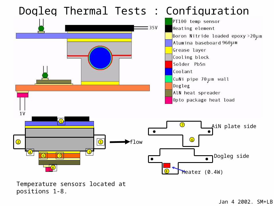
Dogleg Thermal Tests : Configuration
7
6
AiN plate side
Jan 4 2002. SM+LB
8
Dogleg side
Heater (0.4W)
2 1
34
5
6 7
8
flow2
Temperature sensors located at positions 1-8.
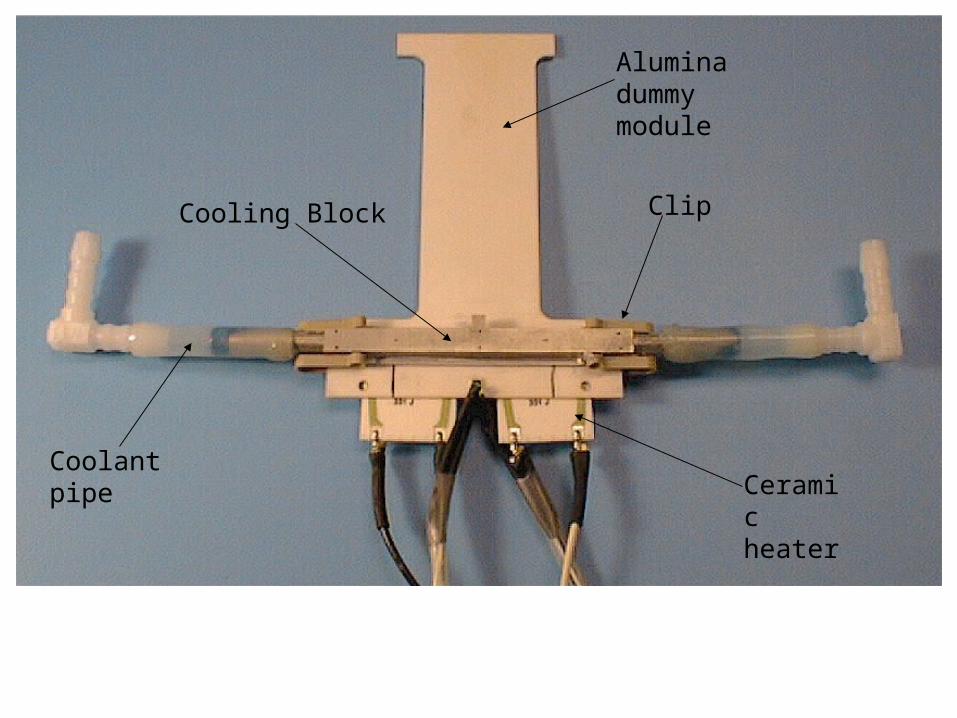
Cooling Block
Alumina dummy module
Clip
Coolant pipeCeramic heater
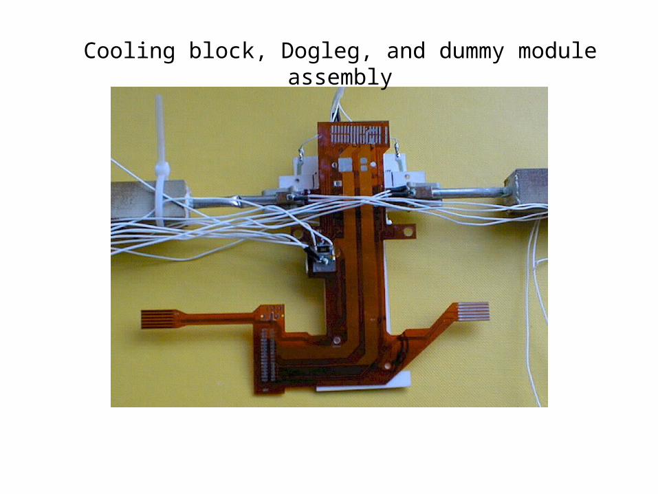
Cooling block, Dogleg, and dummy module assembly
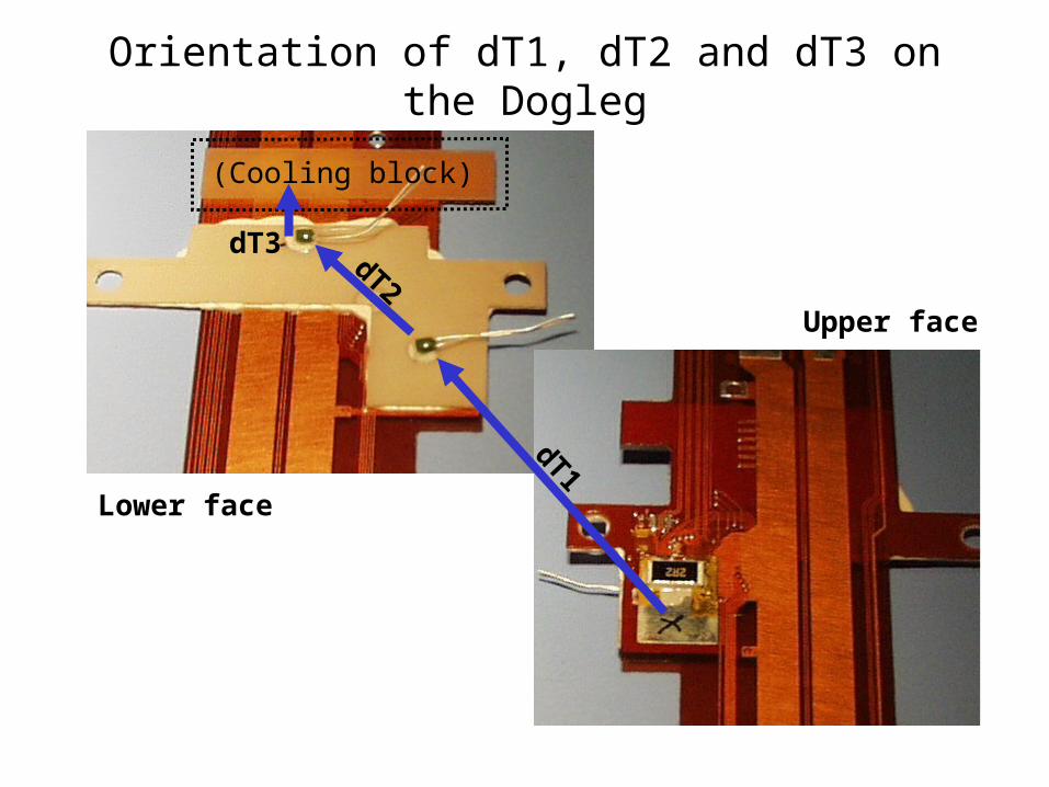
Orientation of dT1, dT2 and dT3 on the Dogleg
dT1
dT2
(Cooling block)
dT3
Upper face
Lower face
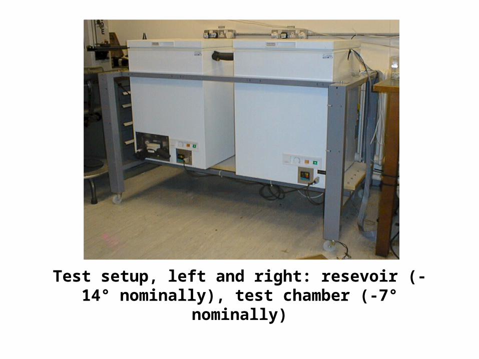
Test setup, left and right: resevoir (-14° nominally), test chamber (-7° nominally)
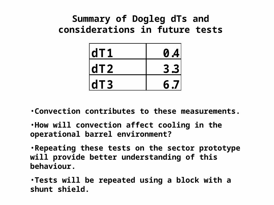
dT1 0.4dT2 3.3dT3 6.7
Summary of Dogleg dTs and considerations in future tests
•Convection contributes to these measurements.
•How will convection affect cooling in the operational barrel environment?
•Repeating these tests on the sector prototype will provide better understanding of this behaviour.
•Tests will be repeated using a block with a shunt shield.
-1
1
3
5
7
9
11
13
-20 -15 -10 -5 0
Environment temp
dT
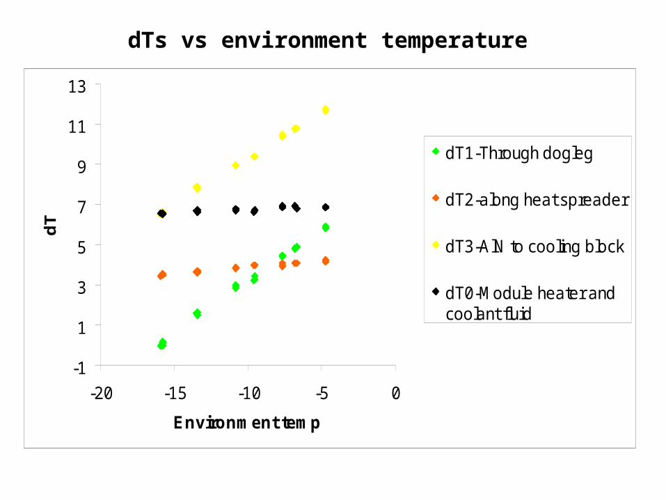
dT1-Through dogleg
dT2-along heat spreader
dT3-AlN to cooling block
dT0-Module heater andcoolant fluid
dTs vs environment temperature
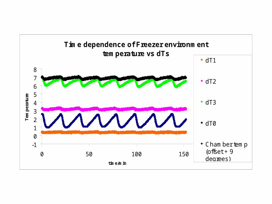
Time dependence of Freezer environment temperature vs dTs
-1012345678
0 50 100 150
time/min
Tem
per
atu
re
dT1
dT2
dT3
dT0
Chamber temp(offset + 9degrees)