Embed Size (px)
Citation preview
Ž. Tekić i dr. Ekserasti metalni konekter - eksperimentalno određivanje nosivosti nastavka drvenog štapa
Tehnički vjesnik 24, 1(2017), 35-42 35
ISSN 1330-3651 (Print), ISSN 1848-6339 (Online) DOI: 10.17559/TV-20150416162209
NAIL METAL CONNECTOR PLATE – EXPERIMENTAL DETERMINATION OF LOAD-BEARING CAPACITY OF TIMBER MEMBER CONNECTIONS Žikica Tekić, Saša Đorđević, Dušan Tomić
Original scientific paper This paper demonstrates the results of experimental determination of load-bearing capacity of structural timber member connections realized by nail metal connector plates which represent a new type of mechanical fasteners in load-bearing timber structures. The application of this type of metal connector should eliminate weakness of the standard metal connector plates produced by sheet perforating and pulling the teeth perpendicular to a sheet plane. The aim of the conducted experimental study was to determine the load-bearing capacity of connections realized by nail metal connector plates, in accordance with the provisions of Eurocode 5. Experimental testing was conducted by loading of multiple samples up to the limit bearing capacity of connection realized by nail metal connector plate. Discussion of the test results included the analysis of the limit bearing capacity of connection for different values of connection displacements, comparison of the obtained results with characteristic load-bearing capacity of standard type of metal connectors and with load-bearing capacity of nails calculated in accordance with limit state theory. Review of the determined limit bearing capacities of realized connections was given in the conclusion, together with the comment on test results, for the purpose of improving the application of metal connectors in modern systems of timber structures. Keywords: displacement; joint; limit bearing capacity; metal connector plate; nail Čavlasta metalna spojnica - eksperimentalno određivanje nosivosti nastavka drvenog štapa
Izvorni znanstveni članak U radu je prikazano eksperimentalno određivanje nosivosti spojeva ostvarenih čavlastim metalnim spojnicama, koji predstavljaju novo mehaničko spojno sredstvo u drvenim konstrukcijama, čija bi primjena trebala eliminirati nedostatke koje imaju standardni tipovi metalnih spojnica, koje se proizvode perforacijom lima i izvlačenjem zubi izvan ravnine lima. Cilj provedenih eksperimentalnih ispitivanja je bio da se utvrdi nosivost spojeva ostvarenih čavlastim metalnim spojnicama, u skladu s odredbama Eurokoda 5. Eksperimentalno ispitivanje je provedeno na više uzoraka, opterećivanjem uzoraka do dostizanja granične nosivosti spoja izvedenog čavlastim metalnim spojnicama. Diskusija rezultata ispitivanja je obuhvatila analizu granične nosivosti spoja za različite vrijednosti pomicanja spoja, usporedbu dobivenih rezultata s karakterističnom nosivošću standardnih tipova metalnih spojnica i računskom nosivošću čavla po teoriji granične nosivosti. U zaključku je dan komentar o utvrđenim graničnim nosivostima ostvarenih spojeva i zauzet je stav po pitanju dobivenih rezultata, u svrhu unaprijeđenja primjene metalnih spojnica u suvremenim sustavima drvenih konstrukcija. Ključne riječi: čavao; granična nosivost; metalna spojnica; nastavak štapa; pomicanje 1 Introduction
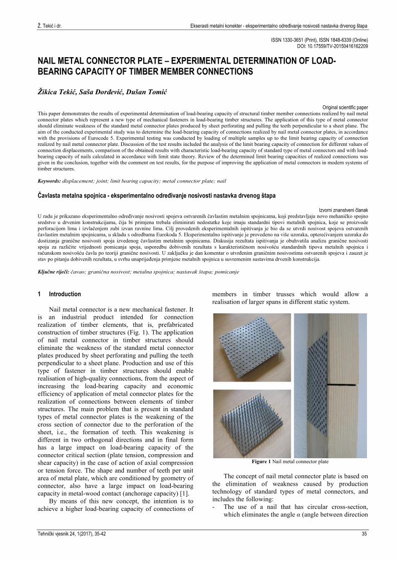
Nail metal connector is a new mechanical fastener. It is an industrial product intended for connection realization of timber elements, that is, prefabricated construction of timber structures (Fig. 1). The application of nail metal connector in timber structures should eliminate the weakness of the standard metal connector plates produced by sheet perforating and pulling the teeth perpendicular to a sheet plane. Production and use of this type of fastener in timber structures should enable realisation of high-quality connections, from the aspect of increasing the load-bearing capacity and economic efficiency of application of metal connector plates for the realization of connections between elements of timber structures. The main problem that is present in standard types of metal connector plates is the weakening of the cross section of connector due to the perforation of the sheet, i.e., the formation of teeth. This weakening is different in two orthogonal directions and in final form has a large impact on load-bearing capacity of the connector critical section (plate tension, compression and shear capacity) in the case of action of axial compression or tension force. The shape and number of teeth per unit area of metal plate, which are conditioned by geometry of connector, also have a large impact on load-bearing capacity in metal-wood contact (anchorage capacity) [1].
By means of this new concept, the intention is to achieve a higher load-bearing capacity of connections of
members in timber trusses which would allow a realisation of larger spans in different static system.
Figure 1 Nail metal connector plate
The concept of nail metal connector plate is based on
the elimination of weakness caused by production technology of standard types of metal connectors, and includes the following: - The use of a nail that has circular cross-section,
which eliminates the angle α (angle between direction
Nail metal connector plate - experimental determination of load-bearing capacity of timber member connections Ž. Tekić et al.
36 Tehnički vjesnik 24, 1(2017), 35-42
of force and direction of the longitudinal axis of connector) which is defined in the case of standard types of metal connectors. This simplifies the procedure of dimensioning of connections realized by nail metal connector plates, since the verification of the anchorage capacity is done only in function of angle β (angle between direction of force and direction of the longitudinal axis of timber member).
- Larger number of nails per unit area of metal plate, in relation to the number of teeth of the standard connector types, in order to achieve a higher load-bearing capacity per unit area, due to the larger number of nails in connection, taking into account the distance between the nails, in order to avoid a local tearing of wood in the place of nails entering the wood.
- Selection of an appropriate diameter of nails, in terms of load-bearing capacity and economic efficiency of connection. By selection of larger diameter of nails, the number of nails per unit area of connecter can be reduced, which is important for the overall capacity of connection, if we take into account the individual load-bearing capacity of nail in connection.
- Selection of appropriate length of nails, i.e., the depth of driving into a wood, in function of the width of the cross section of timber members in connection. Since the nails are installed on both sides of the timber member, the relative position of the top of two opposing nails is important for the load-bearing capacity of connection.
- Selection of appropriate depth of steel sheet for the nail connector plate, in relation to which, including the openings in plate, the net area of cross-section relevant for the dimensioning of critical section of connector is defined (plate tension, compression and shear capacity). Given that for the assessment of anchorage capacity in case of this type of connector is enough to define the net area of cross-section, the calculation is simplified, in comparison with standard metal connector types, by eliminating the angle γ (angle between the direction of the longitudinal axis of connector and the direction of tension, compression or shear force).
2 The concept of nail metal connector
According to the theory of allowable tension force, that is to say, the theory of limit anchorage, analysis of mutual nail distance in relation to the timber fibers’ direction precedes the construction of nail metal connectors. This analysis should enable the right choice of nail position on the metal plate surface.
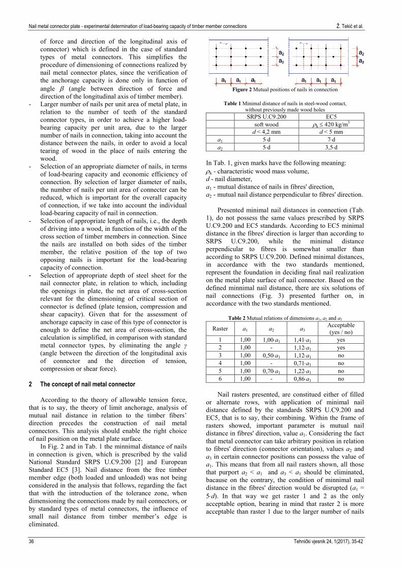
In Fig. 2 and in Tab. 1 the minnimal distance of nails in connection is given, which is prescribed by the valid National Standard SRPS U.C9.200 [2] and European Standard EC5 [3]. Nail distance from the free timber member edge (both loaded and unloaded) was not being considered in the analysis that follows, regarding the fact that with the introduction of the tolerance zone, when dimensioning the connections made by nail connectors, or by standard types of metal connectors, the influence of small nail distance from timber member’s edge is eliminated.
Figure 2 Mutual positions of nails in connection
Table 1 Minimal distance of nails in steel-wood contact,
without previously made wood holes SRPS U.C9.200 EC5 soft wood ρk ≤ 420 kg/m3 d < 4,2 mm d < 5 mm
a1 5⋅d 7⋅d a2 5⋅d 3,5⋅d
In Tab. 1, given marks have the following meaning: ρk - characteristic wood mass volume, d - nail diameter, a1 - mutual distance of nails in fibres' direction, a2 - mutual nail distance perpendicular to fibres' direction.
Presented minimal nail distances in connection (Tab.
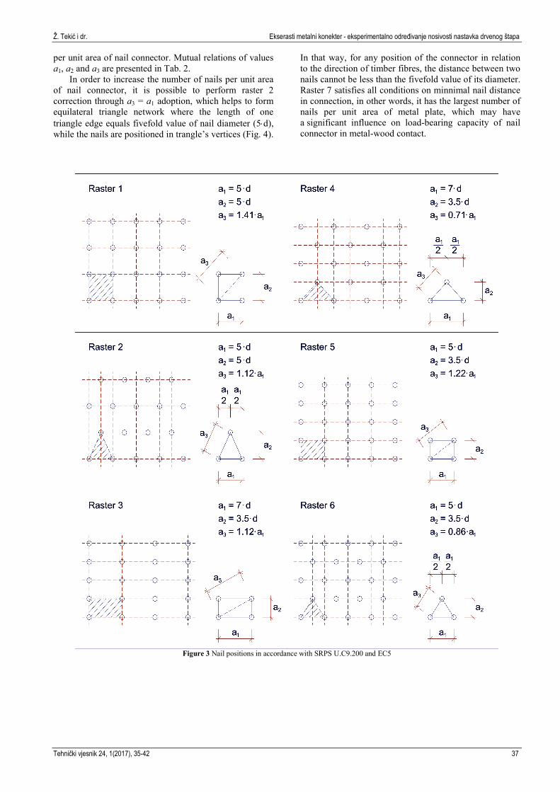
1), do not possess the same values prescribed by SRPS U.C9.200 and EC5 standards. According to EC5 minimal distance in the fibres' direction is larger than according to SRPS U.C9.200, while the minimal distance perpendicular to fibres is somewhat smaller than according to SRPS U.C9.200. Defined minimal distances, in accordance with the two standards mentioned, represent the foundation in deciding final nail realization on the metal plate surface of nail connector. Based on the defined minnimal nail distance, there are six solutions of nail connections (Fig. 3) presented further on, in accordance with the two standards mentioned.
Table 2 Mutual relations of dimensions a1, a2 and a3
Raster a1 a2 a3 Acceptable (yes / no)
1 1,00 1,00⋅a1 1,41⋅a1 yes 2 1,00 - 1,12⋅a1 yes 3 1,00 0,50⋅a1 1,12⋅a1 no 4 1,00 - 0,71⋅a1 no 5 1,00 0,70⋅a1 1,22⋅a1 no 6 1,00 - 0,86⋅a1 no
Nail rasters presented, are constitued either of filled
or alternate rows, with application of minimal nail distance defined by the standards SRPS U.C9.200 and EC5, that is to say, their combining. Within the frame of rasters showed, important parameter is mutual nail distance in fibres' direction, value a1. Considering the fact that metal connector can take arbitrary position in relation to fibres' direction (connector orientation), values a2 and a3 in certain connector positions can possess the value of a1. This means that from all nail rasters shown, all those that purport a2 < a1 and a3 < a1 should be eliminated, bacause on the contrary, the condition of minnimal nail distance in the fibres' direction would be disrupted (a1 = 5⋅d). In that way we get raster 1 and 2 as the only acceptable option, bearing in mind that raster 2 is more acceptable than raster 1 due to the larger number of nails
Ž. Tekić i dr. Ekserasti metalni konekter - eksperimentalno određivanje nosivosti nastavka drvenog štapa
Tehnički vjesnik 24, 1(2017), 35-42 37
per unit area of nail connector. Mutual relations of values a1, a2 and a3 are presented in Tab. 2.
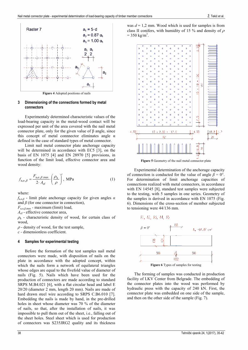
In order to increase the number of nails per unit area of nail connector, it is possible to perform raster 2 correction through a3 = a1 adoption, which helps to form equilateral triangle network where the length of one triangle edge equals fivefold value of nail diameter (5⋅d), while the nails are positioned in trangle’s vertices (Fig. 4).
In that way, for any position of the connector in relation to the direction of timber fibres, the distance between two nails cannot be less than the fivefold value of its diameter. Raster 7 satisfies all conditions on minnimal nail distance in connection, in other words, it has the largest number of nails per unit area of metal plate, which may have a significant influence on load-bearing capacity of nail connector in metal-wood contact.
Figure 3 Nail positions in accordance with SRPS U.C9.200 and EC5
Nail metal connector plate - experimental determination of load-bearing capacity of timber member connections Ž. Tekić et al.
38 Tehnički vjesnik 24, 1(2017), 35-42
Figure 4 Adopted positions of nails
3 Dimensioning of the connections formed by metal
connectors
Experimentaly determined characteristic values of the load-bearing capacity in the metal-wood contact will be expressed per unit of the area covered with the nail metal connector plate, only for the given value of β angle, since this concept of metal connnector eliminates angle α defined in the case of standard types of metal connector.
Limit nail metal connector plate anchorage capacity will be determined in accordance with EC5 [3], on the basis of EN 1075 [4] and EN 28970 [5] provisions, in function of the limit load, effective connector area and wood density:
,2
k
ef
max,a,,a,
c,
AF
f
⋅
⋅=
ρρβa
βa MPa (1)
where: fa,α,β - limit plate anchorage capacity for given angles α and β (for one connector in connection), Fa,α,β,max - maximum (limit) load, Aef - effective connector area, ρk - characteristic density of wood, for certain class of wood, ρ - density of wood, for the test sample, c - dimensionless coefficient. 4 Samples for experimental testing
Before the formation of the test samples nail metal connectors were made, with disposition of nails on the plate in accordance with the adopted concept, within which the nails form a network of equilateral triangles whose edges are equal to the fivefold value of diameter of nails (Fig. 5). Nails which have been used for the production of connectors are made according to standard SRPS M.B4.021 [6], with a flat circular head and label E 20/20 (diameter 2 mm, length 20 mm). Nails are made of hard drawn steel wire according to SRPS C.B6.010 [7]. Embedding the nails is made by hand, in the pre-drilled holes in sheet whose diameter was 70 % of the diameter of nails, so that, after the installation of nails, it was impossible to pull them out of the sheet, i.e., falling out of the sheet holes. Steel sheet which is used for production of connectors was S235JRG2 quality and its thickness
was d = 1,2 mm. Wood which is used for samples is from class II conifers, with humidity of 15 % and density of ρ = 350 kg/m3.
Figure 5 Geometry of the nail metal connector plate
Experimental determination of the anchorage capacity
of connection is conducted for the value of angle β = 0°. For determination of limit anchorage capacities of connections realized with metal connectors, in accordance with EN 14545 [8], standard test samples were subjected to the testing, with 5 samples in one series. Geometry of the samples is derived in accordance with EN 1075 (Fig. 6). Dimensions of the cross-section of member subjected to tensioning were 44/136 mm.
Figure 6 Types of samples for testing
The forming of samples was conducted in production
facility of LKV Center from Belgrade. The embedding of the connector plates into the wood was performed by hydraulic press with the capacity of 240 kN. First, the connector plate was embedded on one side of the sample, and then on the other side of the sample (Fig. 7).
Ž. Tekić i dr. Ekserasti metalni konekter - eksperimentalno određivanje nosivosti nastavka drvenog štapa
Tehnički vjesnik 24, 1(2017), 35-42 39
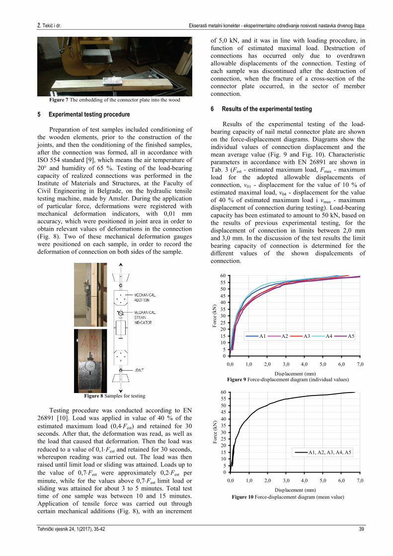
Figure 7 The embedding of the connector plate into the wood
5 Experimental testing procedure
Preparation of test samples included conditioning of the wooden elements, prior to the construction of the joints, and then the conditioning of the finished samples, after the connection was formed, all in accordance with ISO 554 standard [9], which means the air temperature of 20° and humidity of 65 %. Testing of the load-bearing capacity of realized connections was performed in the Institute of Materials and Structures, at the Faculty of Civil Engineering in Belgrade, on the hydraulic tensile testing machine, made by Amsler. During the application of particular force, deformations were registered with mechanical deformation indicators, with 0,01 mm accuracy, which were positioned in joint area in order to obtain relevant values of deformations in the connection (Fig. 8). Two of these mechanical deformation gauges were positioned on each sample, in order to record the deformation of connection on both sides of the sample.
Figure 8 Samples for testing
Testing procedure was conducted according to EN
26891 [10]. Load was applied in value of 40 % of the estimated maximum load (0,4⋅Fest) and retained for 30 seconds. After that, the deformation was read, as well as the load that caused that deformation. Then the load was reduced to a value of 0,1⋅Fest and retained for 30 seconds, whereupon reading was carried out. The load was then raised until limit load or sliding was attained. Loads up to the value of 0,7⋅Fest were approximately 0,2⋅Fest per minute, while for the values above 0,7⋅Fest limit load or sliding was attained for about 3 to 5 minutes. Total test time of one sample was between 10 and 15 minutes. Application of tensile force was carried out through certain mechanical additions (Fig. 8), with an increment
of 5,0 kN, and it was in line with loading procedure, in function of estimated maximal load. Destruction of connections has occurred only due to overdrawn allowable displacements of the connection. Testing of each sample was discontinued after the destruction of connection, when the fracture of a cross-section of the connector plate occurred, in the sector of member connection. 6 Results of the experimental testing
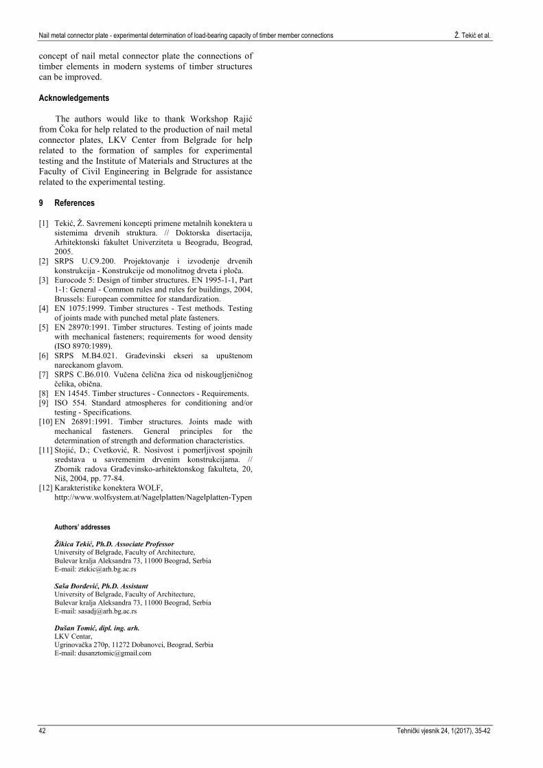
Results of the experimental testing of the load-bearing capacity of nail metal connector plate are shown on the force-displacement diagrams. Diagrams show the individual values of connection displacement and the mean average value (Fig. 9 and Fig. 10). Characteristic parameters in accordance with EN 26891 are shown in Tab. 3 (Fest - estimated maximum load, Fmax - maximum load for the adopted allowable displacements of connection, v01 - displacement for the value of 10 % of estimated maximal load, v04 - displacement for the value of 40 % of estimated maximum load i vmax - maximum displacement of connection during testing). Load-bearing capacity has been estimated to amount to 50 kN, based on the results of previous experimental testing, for the displacement of connection in limits between 2,0 mm and 3,0 mm. In the discussion of the test results the limit bearing capacity of connection is determined for the different values of the shown dispalcements of connection.
05
1015202530354045505560
0,0 1,0 2,0 3,0 4,0 5,0 6,0 7,0
Displacement (mm)
Forc
e (k
N)
A1 A2 A3 A4 A5
Figure 9 Force-displacement diagram (individual values)
05
1015202530354045505560
0,0 1,0 2,0 3,0 4,0 5,0 6,0 7,0
Displacement (mm)
Forc
e (k
N)
A1, A2, A3, A4, A5
Figure 10 Force-displacement diagram (mean value)
Nail metal connector plate - experimental determination of load-bearing capacity of timber member connections Ž. Tekić et al.
40 Tehnički vjesnik 24, 1(2017), 35-42
Table 3 Test results Load Displacement
Sample Fest (kN)
Fmax (kN)
v01 (mm)
v04 (mm)
vmax (mm)
A1 20 47,99 0,105 0,205 5,830 A2 20 45,49 0,095 0,225 7,760 A3 20 45,38 0,090 0,200 6,395 A4 20 50,47 0,075 0,185 6,120 A5 20 43,15 0,155 0,285 7,380
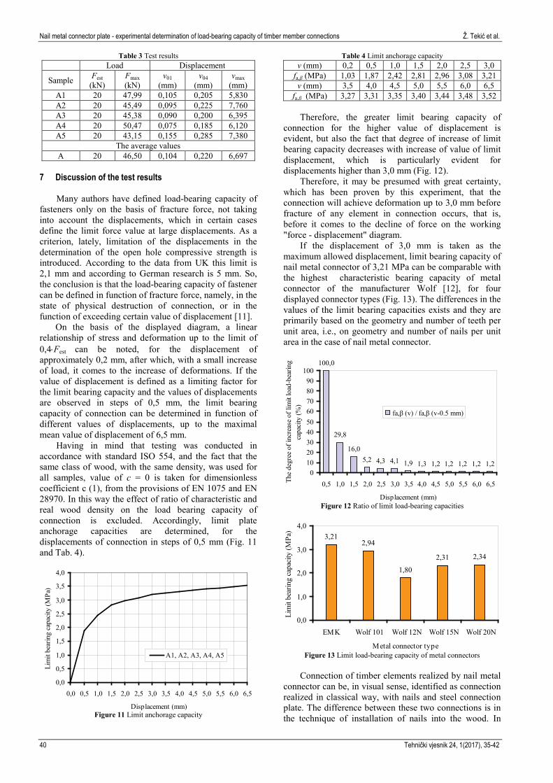
The average values A 20 46,50 0,104 0,220 6,697
7 Discussion of the test results
Many authors have defined load-bearing capacity of fasteners only on the basis of fracture force, not taking into account the displacements, which in certain cases define the limit force value at large displacements. As a criterion, lately, limitation of the displacements in the determination of the open hole compressive strength is introduced. According to the data from UK this limit is 2,1 mm and according to German research is 5 mm. So, the conclusion is that the load-bearing capacity of fastener can be defined in function of fracture force, namely, in the state of physical destruction of connection, or in the function of exceeding certain value of displacement [11].
On the basis of the displayed diagram, a linear relationship of stress and deformation up to the limit of 0,4⋅Fest can be noted, for the displacement of approximately 0,2 mm, after which, with a small increase of load, it comes to the increase of deformations. If the value of displacement is defined as a limiting factor for the limit bearing capacity and the values of displacements are observed in steps of 0,5 mm, the limit bearing capacity of connection can be determined in function of different values of displacements, up to the maximal mean value of displacement of 6,5 mm.
Having in mind that testing was conducted in accordance with standard ISO 554, and the fact that the same class of wood, with the same density, was used for all samples, value of c = 0 is taken for dimensionless coefficient c (1), from the provisions of EN 1075 and EN 28970. In this way the effect of ratio of characteristic and real wood density on the load bearing capacity of connection is excluded. Accordingly, limit plate anchorage capacities are determined, for the displacements of connection in steps of 0,5 mm (Fig. 11 and Tab. 4).
0,0
0,5
1,0
1,5
2,0
2,5
3,0
3,5
4,0
0,0 0,5 1,0 1,5 2,0 2,5 3,0 3,5 4,0 4,5 5,0 5,5 6,0 6,5
Displacement (mm)
Lim
it be
arin
g ca
paci
ty (M
Pa)
A1, A2, A3, A4, A5
Figure 11 Limit anchorage capacity
Table 4 Limit anchorage capacity v (mm) 0,2 0,5 1,0 1,5 2,0 2,5 3,0
fa,β (MPa) 1,03 1,87 2,42 2,81 2,96 3,08 3,21 v (mm) 3,5 4,0 4,5 5,0 5,5 6,0 6,5
fa,β (MPa) 3,27 3,31 3,35 3,40 3,44 3,48 3,52
Therefore, the greater limit bearing capacity of connection for the higher value of displacement is evident, but also the fact that degree of increase of limit bearing capacity decreases with increase of value of limit displacement, which is particularly evident for displacements higher than 3,0 mm (Fig. 12).
Therefore, it may be presumed with great certainty, which has been proven by this experiment, that the connection will achieve deformation up to 3,0 mm before fracture of any element in connection occurs, that is, before it comes to the decline of force on the working "force - displacement" diagram.
If the displacement of 3,0 mm is taken as the maximum allowed displacement, limit bearing capacity of nail metal connector of 3,21 MPa can be comparable with the highest characteristic bearing capacity of metal connector of the manufacturer Wolf [12], for four displayed connector types (Fig. 13). The differences in the values of the limit bearing capacities exists and they are primarily based on the geometry and number of teeth per unit area, i.e., on geometry and number of nails per unit area in the case of nail metal connector.
100,0
29,8
16,05,2 4,3 4,1 1,9 1,3 1,2 1,2 1,2 1,2 1,2
0102030405060708090
100
0,5 1,0 1,5 2,0 2,5 3,0 3,5 4,0 4,5 5,0 5,5 6,0 6,5
Displacement (mm)
The
degr
ee o
f inc
reas
e of
lim
it lo
ad-b
earin
g ca
paci
ty (%
)
fa,β (v) / fa,β (v-0.5 mm)
Figure 12 Ratio of limit load-bearing capacities
3,212,94
1,80
2,31 2,34
0,0
1,0
2,0
3,0
4,0
EMK Wolf 101 Wolf 12N Wolf 15N Wolf 20N
Metal connector type
Lim
it be
arin
g ca
paci
ty (M
Pa)
Figure 13 Limit load-bearing capacity of metal connectors
Connection of timber elements realized by nail metal
connector can be, in visual sense, identified as connection realized in classical way, with nails and steel connection plate. The difference between these two connections is in the technique of installation of nails into the wood. In
Ž. Tekić i dr. Ekserasti metalni konekter - eksperimentalno određivanje nosivosti nastavka drvenog štapa
Tehnički vjesnik 24, 1(2017), 35-42 41
classical way nails are manually installed, while in the case of nail metal connector they are installed in wood under pressure by presses. However, if we take into account the bearing capacity of nails determined by limit state theory, a comparison with the results obtained by conducted experimental tests cannot be adequately performed.
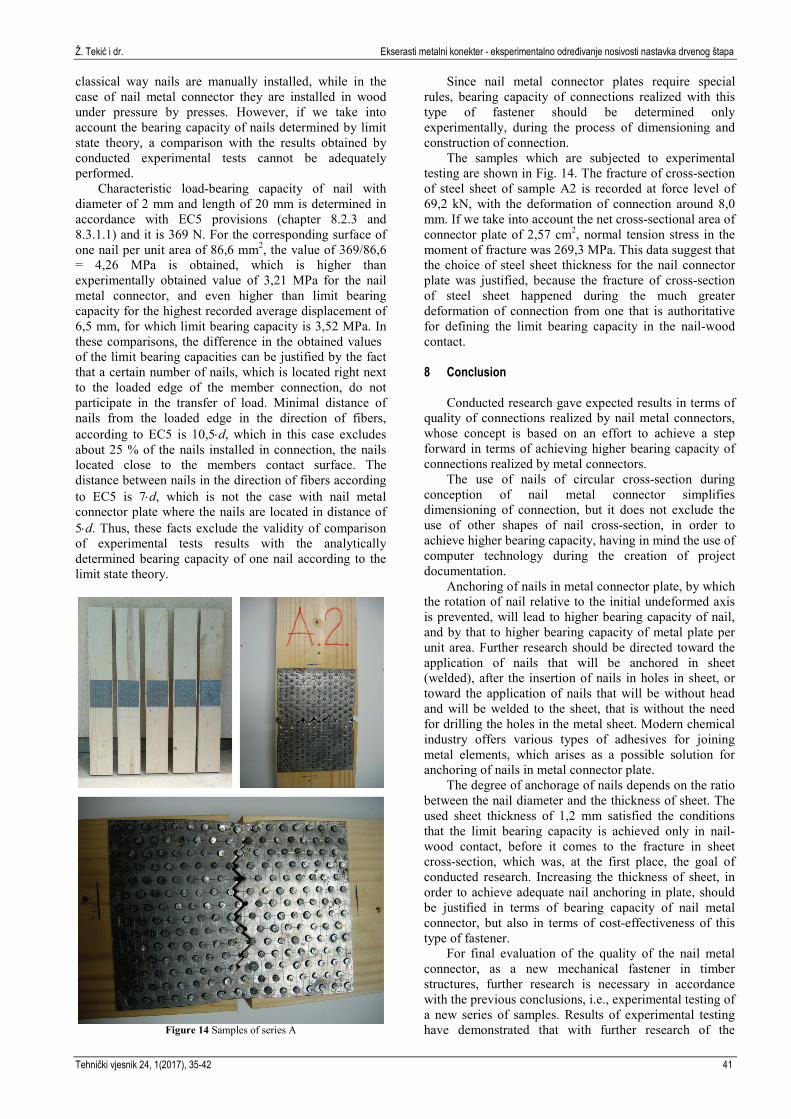
Characteristic load-bearing capacity of nail with diameter of 2 mm and length of 20 mm is determined in accordance with EC5 provisions (chapter 8.2.3 and 8.3.1.1) and it is 369 N. For the corresponding surface of one nail per unit area of 86,6 mm2, the value of 369/86,6 = 4,26 MPa is obtained, which is higher than experimentally obtained value of 3,21 MPa for the nail metal connector, and even higher than limit bearing capacity for the highest recorded average displacement of 6,5 mm, for which limit bearing capacity is 3,52 MPa. In these comparisons, the difference in the obtained values of the limit bearing capacities can be justified by the fact that a certain number of nails, which is located right next to the loaded edge of the member connection, do not participate in the transfer of load. Minimal distance of nails from the loaded edge in the direction of fibers, according to EC5 is 10,5⋅d, which in this case excludes about 25 % of the nails installed in connection, the nails located close to the members contact surface. The distance between nails in the direction of fibers according to EC5 is 7⋅d, which is not the case with nail metal connector plate where the nails are located in distance of 5⋅d. Thus, these facts exclude the validity of comparison of experimental tests results with the analytically determined bearing capacity of one nail according to the limit state theory.
Figure 14 Samples of series A
Since nail metal connector plates require special rules, bearing capacity of connections realized with this type of fastener should be determined only experimentally, during the process of dimensioning and construction of connection.
The samples which are subjected to experimental testing are shown in Fig. 14. The fracture of cross-section of steel sheet of sample A2 is recorded at force level of 69,2 kN, with the deformation of connection around 8,0 mm. If we take into account the net cross-sectional area of connector plate of 2,57 cm2, normal tension stress in the moment of fracture was 269,3 MPa. This data suggest that the choice of steel sheet thickness for the nail connector plate was justified, because the fracture of cross-section of steel sheet happened during the much greater deformation of connection from one that is authoritative for defining the limit bearing capacity in the nail-wood contact. 8 Conclusion
Conducted research gave expected results in terms of quality of connections realized by nail metal connectors, whose concept is based on an effort to achieve a step forward in terms of achieving higher bearing capacity of connections realized by metal connectors.
The use of nails of circular cross-section during conception of nail metal connector simplifies dimensioning of connection, but it does not exclude the use of other shapes of nail cross-section, in order to achieve higher bearing capacity, having in mind the use of computer technology during the creation of project documentation.
Anchoring of nails in metal connector plate, by which the rotation of nail relative to the initial undeformed axis is prevented, will lead to higher bearing capacity of nail, and by that to higher bearing capacity of metal plate per unit area. Further research should be directed toward the application of nails that will be anchored in sheet (welded), after the insertion of nails in holes in sheet, or toward the application of nails that will be without head and will be welded to the sheet, that is without the need for drilling the holes in the metal sheet. Modern chemical industry offers various types of adhesives for joining metal elements, which arises as a possible solution for anchoring of nails in metal connector plate.
The degree of anchorage of nails depends on the ratio between the nail diameter and the thickness of sheet. The used sheet thickness of 1,2 mm satisfied the conditions that the limit bearing capacity is achieved only in nail-wood contact, before it comes to the fracture in sheet cross-section, which was, at the first place, the goal of conducted research. Increasing the thickness of sheet, in order to achieve adequate nail anchoring in plate, should be justified in terms of bearing capacity of nail metal connector, but also in terms of cost-effectiveness of this type of fastener.
For final evaluation of the quality of the nail metal connector, as a new mechanical fastener in timber structures, further research is necessary in accordance with the previous conclusions, i.e., experimental testing of a new series of samples. Results of experimental testing have demonstrated that with further research of the
Nail metal connector plate - experimental determination of load-bearing capacity of timber member connections Ž. Tekić et al.
42 Tehnički vjesnik 24, 1(2017), 35-42
concept of nail metal connector plate the connections of timber elements in modern systems of timber structures can be improved.
Acknowledgements
The authors would like to thank Workshop Rajić from Čoka for help related to the production of nail metal connector plates, LKV Center from Belgrade for help related to the formation of samples for experimental testing and the Institute of Materials and Structures at the Faculty of Civil Engineering in Belgrade for assistance related to the experimental testing.
9 References
[1] Tekić, Ž. Savremeni koncepti primene metalnih konektera u sistemima drvenih struktura. // Doktorska disertacija, Arhitektonski fakultet Univerziteta u Beogradu, Beograd, 2005.
[2] SRPS U.C9.200. Projektovanje i izvodenje drvenih konstrukcija - Konstrukcije od monolitnog drveta i ploča.
[3] Eurocode 5: Design of timber structures. EN 1995-1-1, Part 1-1: General - Common rules and rules for buildings, 2004, Brussels: European committee for standardization.
[4] EN 1075:1999. Timber structures - Test methods. Testing of joints made with punched metal plate fasteners.
[5] EN 28970:1991. Timber structures. Testing of joints made with mechanical fasteners; requirements for wood density (ISO 8970:1989).
[6] SRPS M.B4.021. Građevinski ekseri sa upuštenom nareckanom glavom.
[7] SRPS C.B6.010. Vučena čelična žica od niskougljeničnog čelika, obična.
[8] EN 14545. Timber structures - Connectors - Requirements. [9] ISO 554. Standard atmospheres for conditioning and/or
testing - Specifications. [10] EN 26891:1991. Timber structures. Joints made with
mechanical fasteners. General principles for the determination of strength and deformation characteristics.
[11] Stojić, D.; Cvetković, R. Nosivost i pomerljivost spojnih sredstava u savremenim drvenim konstrukcijama. // Zbornik radova Građevinsko-arhitektonskog fakulteta, 20, Niš, 2004, pp. 77-84.
[12] Karakteristike konektera WOLF, http://www.wolfsystem.at/Nagelplatten/Nagelplatten-Typen
Authors’ addresses
Žikica Tekić, Ph.D. Associate Professor University of Belgrade, Faculty of Architecture, Bulevar kralja Aleksandra 73, 11000 Beograd, Serbia E-mail: [email protected]
Saša Đorđević, Ph.D. Assistant University of Belgrade, Faculty of Architecture, Bulevar kralja Aleksandra 73, 11000 Beograd, Serbia E-mail: [email protected]
Dušan Tomić, dipl. ing. arh. LKV Centar, Ugrinovačka 270p, 11272 Dobanovci, Beograd, Serbia E-mail: [email protected]