Embed Size (px)
Citation preview

Dokalman University of Cincinnati
24 th Annual Intelligent Ground Vehicle Competition
Joseph Knight ✦ Christopher Crowell ✦ Kenneth Fechter ✦ Douglas Flick Lucas Boswell ✦ Andrew Robb ✦ Morgan Best ✦ Evan Baumann ✦ Elana Wetzler
Submitted May 15th, 2016
CERTIFICATION: I certify that the engineering design in the vehicle Dokalman (original and changes) by the current student team identi�ed in this Design Report has been signi�cant and equivalent to what might be awarded credit in a senior design course.
_______________________________________ Professor Paul Talaga, Advisor [email protected]
1

Introduction
The University of Cincinnati Robotics Team �rst entered a robot under the name Dokalman in the 22 nd Intelligent Ground Vehicle Competition. In the three years since its original design, we have made signi�cant improvements to the hardware, electrical and software design of the robot. The following list of improvements have been since the last IGVC competition.
● The electrical system has been completely redesigned and rebuilt ○ Power Distribution Units were installed in order to programmatically control and
monitor power consumption of devices. ○ High and low Voltage limits have now been added for all of the electronics. This
provides protection from low battery issues or charging problems. ○ A new wireless E-Stop system cuts the power to the motion controller digitally, so
the robot software can detect an E-Stop situation. ● The software system has been restructured for more �exibility
○ The ATX motherboard was replaced with two NUC’s (Intel Next Unit of Computing), and one Raspberry Pi 2. This signi�cantly improves power ef�ciency, increasing the computing power available, while also decreasing the amount of power being consumed. We can now scale the computing resources available to meet the task at hand. For example, when piloting up the robot manually, only the Raspberry Pi is needed.
○ Nearly all devices on Dokalman communicate over the TCP/IP network. All critical devices are statically addressed on a layer 2 network contained within the robot. When testing or debugging, the robot network is bridged with the base state network via long range wireless network. This allows communication directly between robot computers without following closely behind the robot.
○ A switch from the single high resolution camera to multiple cameras gives Dokalman a wider viewing angle for obstacle avoidance.
○ New line-detection code better handles changes in ambient lighting. This is done by looking at relative differences within the image instead of absolute reference points.
○ A new GPS antenna and radio controller were added for increased accuracy on the �eld.
● The body of the robot was stripped down to the frame and redesigned. ○ The new acrylic panels better encapsulate the electronics for safety and water
resistance. ○ 3D-printed panel anchors and thumb screw attachments allow for quick, tool-free
removal of body panels for servicing. The function of these changes is further explained in the following sections describing the control and hardware system design for Dokalman.
2

Team Organization
This year, the team was signi�cantly smaller compared to previous years, allowing for team members to take on large responsibilities for the completion of the robot. Team members were able to carry out full life cycle development as the robot progressed from prototype to end product. Coordination between roles was perpetual as each constituent layer of the design was worked on simultaneously.
Role Name Major Email* Grad Year
Captain/ Software Lead Joseph Knight Computer Engineering knightjp 2018
Hardware Lead Evan Baumann Mechanical Engineering baumanea 2020
Vision Lead Douglas Flick Computer Science �ickdm 2018
Software/Hardware Christopher Crowell Computer Science crowelch 2016
Documentation Elana Wetzler Finance wetzleec 2017
Software/Hardware Andrew Robb Computer Engineering robbaj 2018
Software Kenneth Fechter Biomedical Engineering fechteka 2016
Hardware Lucas Boswell Electrical Engineering boswellj 2018
Documentation Morgan Best Computer Science bestmc 2019
*Note: Emails are suffixed [email protected]
Design Process
The design process of this year’s Dokalman was carried out simultaneously by the vision, software, and hardware teams. Teams worked closely together in order to coordinate interconnected components and the boundaries between design layers.
Hardware Design
Frame Design
The updated hardware that went into this year’s Dokalman relied greatly upon CAD and 3D printing technology. Dokalman’s design was created through the use of Solid Edge and Solidworks software. While Solid Edge had been used in the past, the team took advantage of courses offered by the University of Cincinnai and added the use of Solidworks to design the new outer shell, the mounting for the electronics, and new
3
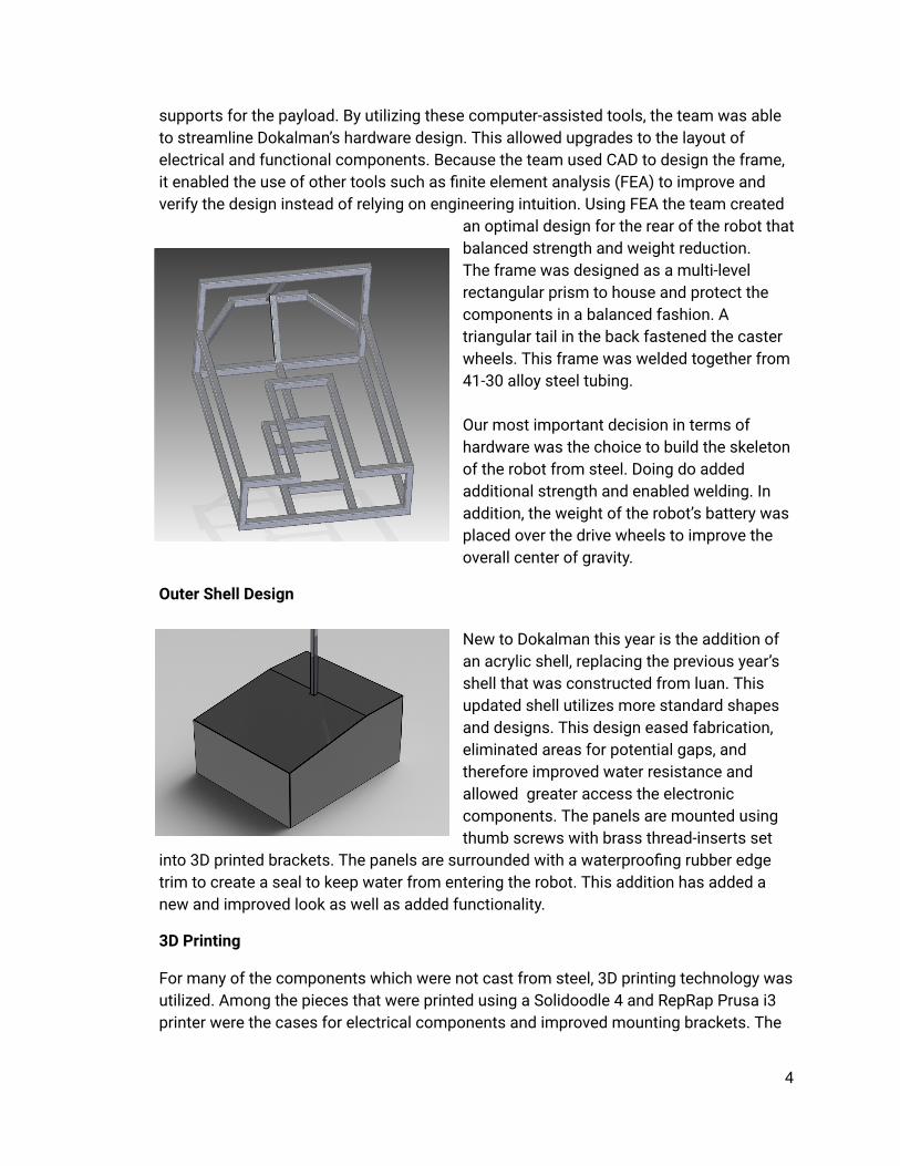
supports for the payload. By utilizing these computer-assisted tools, the team was able to streamline Dokalman’s hardware design. This allowed upgrades to the layout of electrical and functional components. Because the team used CAD to design the frame, it enabled the use of other tools such as �nite element analysis (FEA) to improve and verify the design instead of relying on engineering intuition. Using FEA the team created
an optimal design for the rear of the robot that balanced strength and weight reduction. The frame was designed as a multi-level rectangular prism to house and protect the components in a balanced fashion. A triangular tail in the back fastened the caster wheels. This frame was welded together from 41-30 alloy steel tubing. Our most important decision in terms of hardware was the choice to build the skeleton of the robot from steel. Doing do added additional strength and enabled welding. In addition, the weight of the robot’s battery was placed over the drive wheels to improve the overall center of gravity.
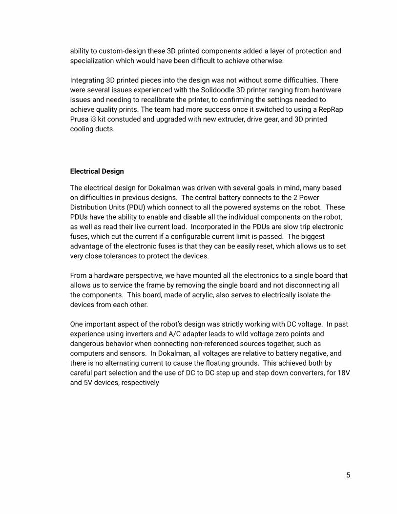
Outer Shell Design New to Dokalman this year is the addition of an acrylic shell, replacing the previous year’s shell that was constructed from luan. This updated shell utilizes more standard shapes and designs. This design eased fabrication, eliminated areas for potential gaps, and therefore improved water resistance and allowed greater access the electronic components. The panels are mounted using thumb screws with brass thread-inserts set
into 3D printed brackets. The panels are surrounded with a waterproo�ng rubber edge trim to create a seal to keep water from entering the robot. This addition has added a new and improved look as well as added functionality.
3D Printing
For many of the components which were not cast from steel, 3D printing technology was utilized. Among the pieces that were printed using a Solidoodle 4 and RepRap Prusa i3 printer were the cases for electrical components and improved mounting brackets. The
4
ability to custom-design these 3D printed components added a layer of protection and specialization which would have been dif�cult to achieve otherwise. Integrating 3D printed pieces into the design was not without some dif�culties. There were several issues experienced with the Solidoodle 3D printer ranging from hardware issues and needing to recalibrate the printer, to con�rming the settings needed to achieve quality prints. The team had more success once it switched to using a RepRap Prusa i3 kit constuded and upgraded with new extruder, drive gear, and 3D printed cooling ducts.
Electrical Design
The electrical design for Dokalman was driven with several goals in mind, many based on dif�culties in previous designs. The central battery connects to the 2 Power Distribution Units (PDU) which connect to all the powered systems on the robot. These PDUs have the ability to enable and disable all the individual components on the robot, as well as read their live current load. Incorporated in the PDUs are slow trip electronic fuses, which cut the current if a con�gurable current limit is passed. The biggest advantage of the electronic fuses is that they can be easily reset, which allows us to set very close tolerances to protect the devices. From a hardware perspective, we have mounted all the electronics to a single board that allows us to service the frame by removing the single board and not disconnecting all the components. This board, made of acrylic, also serves to electrically isolate the devices from each other. One important aspect of the robot’s design was strictly working with DC voltage. In past experience using inverters and A/C adapter leads to wild voltage zero points and dangerous behavior when connecting non-referenced sources together, such as computers and sensors. In Dokalman, all voltages are relative to battery negative, and there is no alternating current to cause the �oating grounds. This achieved both by careful part selection and the use of DC to DC step up and step down converters, for 18V and 5V devices, respectively
5

The electrical diagram to the left describes the hierarchy of powered devices in the robot. Each line off the PDU can be individually measured and disabled. An important electrical improvement allows the main battery to be swapped out by connecting a new battery in parallel and removing the drained one. This allows the team to hot-swap batteries for longer runtime, or plug the charger directly into the robot and run off external power
With the improvements made to power distribution, the robot can operate in competition mode for 34 hours of continuous use. However, in lower functionality mode, Dokalman can last significantly lower. The largest power demand for the robot are the NUC computer cluster and the motion controller. If the robot is running at idle, without moving, it will last for 20 hours running the master controller and networking gear.
Wireless E-stop System Design
Dokalman’s estop system was upgraded this year to be simpler and better integrated into the robot’s electrical system. When the wireless e-stop button is pressed, a dedicated e-stop AVR disables the robot’s motion controller by disabling the power channel on our power distribution board. This prevents powered motion, and the motors bring the robot to a sudden stop. The advantage of this system is the fact that the control system can detect the disabled motion controller and stop the software from commanding motion as well as displaying an e-stop warning on the safety light.
6
Software Design
Dokalman is built using the ROS, or Robot Operating System, framework. ROS speci�es a method of data exchange between independent software codebases working in a network to control the robot's position. ROS �ts within the team's development style because it leads to concurrent development, test isolation and well compartmentalized code.
Vision System Design
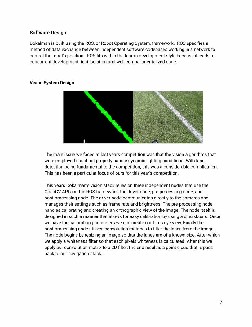
The main issue we faced at last years competition was that the vision algorithms that were employed could not properly handle dynamic lighting conditions. With lane detection being fundamental to the competition, this was a considerable complication. This has been a particular focus of ours for this year's competition. This years Dokalman’s vision stack relies on three independent nodes that use the OpenCV API and the ROS framework: the driver node, pre-processing node, and post-processing node. The driver node communicates directly to the cameras and manages their settings such as frame rate and brightness. The pre-processing node handles calibrating and creating an orthographic view of the image. The node itself is designed in such a manner that allows for easy calibration by using a chessboard. Once we have the calibration parameters we can create our birds eye view. Finally the post-processing node utilizes convolution matrices to �lter the lanes from the image. The node begins by resizing an image so that the lanes are of a known size. After which we apply a whiteness �lter so that each pixels whiteness is calculated. After this we apply our convolution matrix to a 2D �lter.The end result is a point cloud that is pass back to our navigation stack.
7

GPS System Design
To localize the robot on earth, Dokalman is equipped with Novatel Propak V3 GPS and ampli�ed antenna. Via a serial interface on NUC1, the NMEA output from the GPS parsed at a 2 hz rate within the robot software. This GPS location is used to �nd the location of the robot on earth, in UTM coordinates to the nearest origin point. This transform is inversely broadcast as a descendant of the map frame of the robot, to prevent reparenting of the �xed map frame. With this transform, any other UTM coordinate can be translated to a relative transform from the robot. Using this system, the way�nding software simply attaches UTM translated goals in this frame for the robot to navigate.
Navigation System Design
The navigation system is a multi-level software system designed to learn and store the robot's location, as well as the locations of all obstacles around it. By recording the entire environment into a virtual map, smarter path�nding decisions can be made. The lowest level of localization focuses on compiling wheel encoder and accelerometer data to generate accurate odometry for the robot. There were several design choices made to improve the accuracy of this data, including large tractor tires which smoothes out bumps and ruts in the terrain. The high percentage of the robot’s weight on the drive wheels reduces wheel slippage. Most importantly, the wheel encoder data is passed through an extended kalman �lter with the output of a 3D accelerometer to detect slippage during acceleration and braking. All combined, the odometry allows the robot to continuously evaluate its position relative to start. While still prone to signi�cant drift over time, the odometry provides a continuous local path of the robot. To correct the long term drift in the dead reckoning odometry layer, the second layer of software was added to focus on localizing the relative frame of the odometry with corrective edits to anchor it to the earth. Two additional sensors are used for this purpose. GPS location is used as an absolute position with covariance. LIDAR scans are continually evaluated against the virtual map built of previous scans to localize the robot within its map. Using the gmapping algorithm package, this correction is made on top of the odometry to provide error correction. With these two layers, the robot is capable of localizing its movement within its environment. On top of the localization layers, the third layer serves an in-memory map of the environment around the robot. As the robot encounters obstacles by either LIDAR or computer vision, it records the obstacle’s position relative to the robot. This obstacle layer is translated to the real world position using the transform frames assembled by the �rst two localization layers. Obstacles are assigned a cost value based on their certainty and size. A edge smoothing algorithm then expands the obstacles to keep account for the width of Dokalman and driving error
8
With a two-dimensional map of the environment around the robot, combined with the accurate position of the robot within this map, the route planning algorithm can pick an optimum route to an arbitrary goal on the map. Dokalman splits this planning across a local and global planner, focusing on the short term obstacles and long term goals, respectively. Leveraging the move_base module of the ROS navigation stack, Dokalman continually makes adjustments to the route as new obstacles are found and recorded in the map. By basing the route on an ever-improving map the world, Dokalman avoids looping paths and circular traps that cause major issues for reactive robot software platforms. At the highest level of the robot’s software, the goal setting layer chooses the target for the route planning layer to work on. GPS coordinates are converted to the UTM system and then mapped relative to the UTM navigation frame. When goals are reached, the new goal is set.
Network System Design
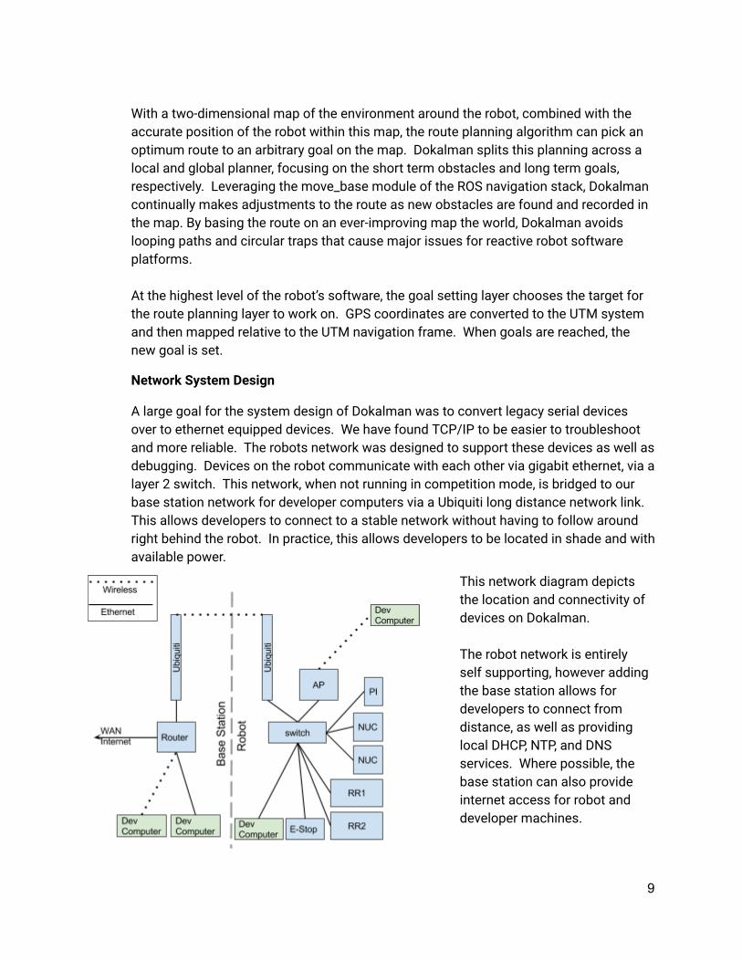
A large goal for the system design of Dokalman was to convert legacy serial devices over to ethernet equipped devices. We have found TCP/IP to be easier to troubleshoot and more reliable. The robots network was designed to support these devices as well as debugging. Devices on the robot communicate with each other via gigabit ethernet, via a layer 2 switch. This network, when not running in competition mode, is bridged to our base station network for developer computers via a Ubiquiti long distance network link. This allows developers to connect to a stable network without having to follow around right behind the robot. In practice, this allows developers to be located in shade and with available power.
This network diagram depicts the location and connectivity of devices on Dokalman. The robot network is entirely self supporting, however adding the base station allows for developers to connect from distance, as well as providing local DHCP, NTP, and DNS services. Where possible, the base station can also provide internet access for robot and developer machines.
9
Failure Handling
In our past IGVC experience, the most common failure mode was accidental switchback when navigating the course. This was because of the reactive nature of the software design, Dokalman solves these issues by keeping a long term memory of the walls it has encountered. When the robot is started, it is instructed of an obstacle zone behind the robot. From that point forward, the robot will create a closed tunnel and be unable to plot a route backwards. On a local scale, the robot has a 3 strike error where it will stop �ipping between 2 routes if an oscillation is detected. At this point the robot will not recalculate for a cooldown window, forcing a new set of parameters to prevent deadlock. At a software level, all unhandled exceptions will take down a portion of the robot’s software network. At this point the the master controller will relaunch the node if it is a node that can handle restarts or stop the entire robot if the error is fatal. For debugging error states, we also have additional color coding on the safety light for the robot. While the rules specify a on, off and blinking state for the safety light, we have extended this behavior to indicate error states on the robot using different colors. Idle, manual pilot, auto navigation, estop and low battery all have colors visible at distance.
10
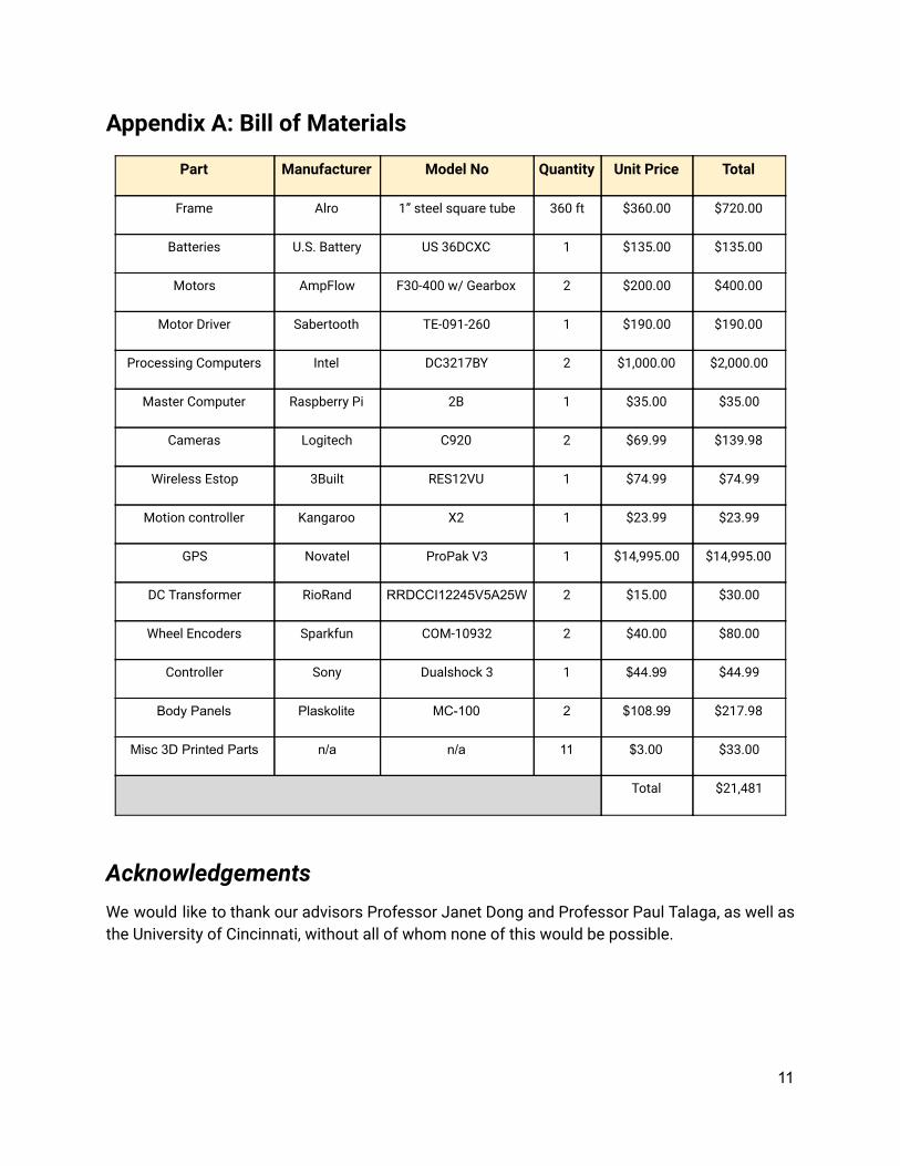
Appendix A: Bill of Materials
Part Manufacturer Model No Quantity Unit Price Total
Frame Alro 1” steel square tube 360 ft $360.00 $720.00
Batteries U.S. Battery US 36DCXC 1 $135.00 $135.00
Motors AmpFlow F30-400 w/ Gearbox 2 $200.00 $400.00
Motor Driver Sabertooth TE-091-260 1 $190.00 $190.00
Processing Computers Intel DC3217BY 2 $1,000.00 $2,000.00
Master Computer Raspberry Pi 2B 1 $35.00 $35.00
Cameras Logitech C920 2 $69.99 $139.98
Wireless Estop 3Built RES12VU 1 $74.99 $74.99
Motion controller Kangaroo X2 1 $23.99 $23.99
GPS Novatel ProPak V3 1 $14,995.00 $14,995.00
DC Transformer RioRand RRDCCI12245V5A25W 2 $15.00 $30.00
Wheel Encoders Sparkfun COM-10932 2 $40.00 $80.00
Controller Sony Dualshock 3 1 $44.99 $44.99
Body Panels Plaskolite MC100 2 $108.99 $217.98
Misc 3D Printed Parts n/a n/a 11 $3.00 $33.00
Total $21,481
Acknowledgements We would like to thank our advisors Professor Janet Dong and Professor Paul Talaga, as well as the University of Cincinnati, without all of whom none of this would be possible.
11


![Official Competition Details, Rules and Format - IGVC · 2017. 1. 10. · [Type here] Official Competition Details, Rules and Format The 25 th Annual Intelligent Ground Vehicle Competition](https://img.pdfslide.net/doc/110x75/60af5bb233a0a8179d69c69a/official-competition-details-rules-and-format-2017-1-10-type-here-official.jpg)