Embed Size (px)
Citation preview


1
DOMUS - THE COMPLETE SOLUTION 2
A GUIDE TO VENTILATION 3 - 7
DUCTING 8 - 46OUTLETS, GRILLES & VENTILATORS 9
SYSTEM 100 14
SUPERTUBE 125 17
MEGADUCT 20
POLYVENT 22
EASIPIPE 25
THERMAPIPE 30
FLEXIBLE DUCTING 33
BOXED KITS 37
Air Supply Sets 37
Flexible Hose Ducting Kits 39
Wall Outlet Sets 41
Flat Channel Ducting Kits 43
Extractor Fan Kit 44
Tumble Dryer Kits 45
Round Pipe Ducting Kits 46
FIREBRAKE 47 - 50
FANS 51 - 78100MM
Axial Fans 52
Axial DiscFans 56
Centrifugal Fans 58
In-Line Fans 60
125MM
Axial Fans 64
in-Line Fans 66
150MM
Axial Fans 68
In-Line Fans 72
12V TRANSFORMERS 74
MULTI ROOM EXTRACT SYSTEM 75
ELF FANS 77
INDEX BY CODE 79-80
CONTENTS

FEATURES OF THE DOMUS VENTILATION RANGE
All products are:
● Independently tested for performance and safety
● Adhere to the relevant Building Regulations
● Manufactured to strict quality control procedures
● Use recycled materials wherever possible
● Designed with ease of installation in mind
● Suitable for a variety of applications
Domus offers:
● An ever expanding and improving range
● Excellent technical support
Domus Ventilation Limited offersthe complete solution to modernventilation requirements.
Domus has a long and distinguished record
of providing effective ducting systems
to channel unwanted air from buildings to
alleviate the problems caused by moisture
and indoor pollutants. To complement the
comprehensive range of ducting, Domus also
has a range of quality, high performance
domestic extractor fans. Together these
products provide the most effective way of
meeting the demands of the Building
Regulations.
Domus systems are ideal for the ventilation of
domestic kitchens and bathrooms and light
industrial and commercial premises.
Domus is seen as an invaluable source of
advice and information on all aspects of
choosing and installing an appropriate
ventilation system. It is this, together with
manufacturing bases in Britain and Poland,
that has enabled Domus to become a global
name in ventilation.
With fans and ducting both manufactured by
one source, Domus can offer a complete 'one
stop' solution to today's domestic ventilation
requirements.
DOMUS - THE COMPLETE SOLUTION
2

3
VENTILATION CONSIDERATIONS
Effective ventilation is now a primary
consideration in the design and construction
of all buildings.
Greater use of sealed heating systems, double
glazing, and increased insulation combined
with the moisture created in kitchens and
bathrooms, makes efficient ventilation a
high priority.
There are many issues facing the designer of
ventilation installations in today's buildings.
They include: the assessment of correct
extraction rates, the power and correct
siting of the extractor, establishing the source
of return air, whilst taking into account
energy saving issues and the correct choice
of ducting through which air must
efficiently flow.
WHERE TO SITE YOUR FAN
One of the main problems that can reduce the
efficiency of an extractor fan is poor siting.
There are a number of basic rules that can be
applied in order to ensure that a fan is
correctly sited:
Rules• Always install the fan in the furthest
window, wall or ceiling from the main air
inlet point and at a high level. This will
ensure maximum airflow of fresh air
throughout the whole room.
• Always ensure that there is sufficient
provision for replacement fresh air into the
room by using internal grilles in the door,
ceiling or wall.
• If installing a fan in a room containing a
fuel-burning device which has a non-
balanced flue, there must be sufficient
replacement air to prevent fumes being
drawn down the flue when the fan is on
maximum extract. (See BS 5440 & Building
Regulations for specific requirements.)
• Exhaust air must not be discharged into a
flue used for exhausting fumes from
appliances supplied with energy other than
electricity. When deciding the method for
exhaust air discharge and intake flow rates,
the requirements of all relevant authorities
must be strictly adhered to.
• Do not site fans where temperatures are
likely to exceed 40ºC.
• Wiring should be carried out in accordance
with current IEE Regulations (UK) or
standards of the country in question.
• Ensure that the instructions provided are
followed during installation, with particular
care taken to check the supply voltage, fuse
rating and wiring are correct.
• IEE regulations require mains voltage fans
to be positioned out of arms reach of the
person using the bath or shower.
i.e. Outside zone 0,1 or 2 as stated in
amendment 3 of B7671:1992. Mains
voltage fans and controls should also be
sited away from potential water spray.
• Always use an In-line Duct or Safety
Extra Low Voltage (SELV) fan to ventilate
a shower cubicle (zone 1). The mains
voltage transformer control unit with SELV
output must be positioned away from any
potential water spray and out of arms’
reach (outside of zone 0, 1 or 2) of the
person using the bath or shower.
• If the duct passes through an unheated roof
void the duct should be insulated to reduce
the formation of condensation. A vertical
duct should also be installed with a
weatherproof roof cowl of sufficient free
area for the air volume. A condensation
trap must be fitted in order to release the
condensation build up. Horizontal ducts
should fall away from the fan unit.
• If the duct passes through a fire
compartment wall, a Domus FireBrake
must be used to maintain the integrity
in accordance with B3 Building Regulations
of 2000 and 2002.
The solid red arrow shows correct airflow
A GUIDE TO VENTILATION
BUILDING REGULATIONS
Since 1990 the UK Building Regulations have
recognised the importance of ventilation in
domestic dwellings, with the publication of
Document F1 and from this date all new
buildings and approved extensions must
make provision for ventilation in kitchens,
utility rooms, bathrooms, shower rooms
and WCs.
Domus has always advocated the need for
ventilation in order to create a healthier
living environment. The products shown in
this catalogue all exceed the current revision
(1995) of the UK Building Regulations when
used in the correct application.
The recommended extract rate for a
domestic kitchen is 60 l/s, that can be
reduced to 30 l/s if a cooker hood is used or
the extract fan is over the hob. Utility rooms
if accessible from inside the dwelling: 30 l/s;
bathrooms and shower rooms: 15 l/s and
separate WCs: 6 l/s. In addition, if any of the
rooms have non-openable windows, the
extract fan must incorporate a timer capable
of a 15 minute overrun.
The table summarises the requirements that
the F1 Building Regulations place on the
efficient ventilation of rooms. Although this
table applies specifically to England, Wales
and (since December 1999) Scotland, it can
be applied as a general guide for most
countries, although climatic conditions may
have an effect on the requirements.
4
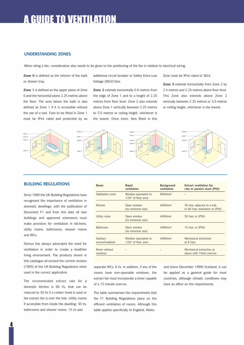
Zone 0 is defined as the interior of the bath
or shower tray.
Zone 1 is defined as the upper plane of Zone
0 and the horizontal plane 2.25 metres above
the floor. The area below the bath is also
defined as Zone 1 if it is accessible without
the use of a tool. Fans to be fitted in Zone 1
must be IPx4 rated and protected by an
additional circuit breaker or Safety Extra Low
Voltage (SELV) fans.
Zone 2 extends horizontally 0.6 metres from
the edge of Zone 1 and to a height of 2.25
metres from floor level. Zone 2 also extends
above Zone 1 vertically between 2.25 metres
to 3.0 metres or ceiling height, whichever is
the lowest. Once more, fans fitted in this
Zone must be IPx4 rated or SELV.
Zone 3 extends horizontally from Zone 2 by
2.4 metres and 2.25 metres above floor level.
This Zone also extends above Zone 2
vertically between 2.25 metres or 3.0 metres
or ceiling height, whichever is the lowest.
2.4m
3m2.25m
0.6m
2.4m
3m2.25m
0.6m
2.4m
3m2.25m
.05m
0.6m
2.4m
3m2.25m
.05m
0.6m
zone 1
zone 2
zone 0
zone 3
zone 2
zone 0
zone 1
zone 2
zone 3
zone 0
zone 1
zone 2
zone 3
zone 0
zone 1
zone 2
zone 3
A GUIDE TO VENTILATION
Room Rapid Background Extract ventilation fanventilation ventilation rate or passive stack (PSV)
Habitation room Window equivalent to 8000mm2 –1/20th of floor area
Kitchen Open window 4000mm2 30 l/sec adjacent to a hob(no minimum size) or 60 l/sec elsewhere or (PSV)
Utility room Open window 4000mm2 30 l/sec or (PSV)(no minimum size)
Bathroom Open window 4000mm2 15 l/sec or (PSV)(no minimum size)
Sanitary Window equivalent to 4000mm2 Mechanical extraction accommodation 1/20th of floor area at 6 l/sec
Room without – – Mechanical extraction aswindows above with 15min overrun
UNDERSTANDING ZONES
When siting a fan, consideration also needs to be given to the positioning of the fan in relation to electrical wiring.

5
PROBLEMS AND SOLUTIONS
Ensuring air quality of the highest standard
significantly reduces the problems caused by
damp, condensation and unwanted smells
that may prove a risk to the inhabitants or
structure of a building.
Inadequate ventilation can cause many
problems:
• Condensation.
• Dampness and potential mould growth.
• Unwanted kitchen smells throughout
the house.
• Old and stale air remaining in the building
resulting in a lack of new, fresh and
healthy air.
These problems create a building that has an
unpleasant living environment. However,
appropriate action can be taken.
• Always turn the fan on before bathing,
taking a shower or cooking.
• Always close internal doors leading to
other parts of the building.
• Always allow a buffer zone after bathing,
showering or cooking by keeping the fan
turned on for a short period of time.
• Always fit the correct size of ducting to
ensure maximum performance of the fan.
The following pages are designed to
give guidance on general ventilation
ducting installation.
A GUIDE TO VENTILATION
FAN SELECTION
The extraction rates recommended by the UK
Building Regulations should be seen as the
minimum requirement. A more accurate
method of calculating the optimum rate, or if
the room to be ventilated is not covered by
the Regulations, is as follows:
1. Measure the length, breadth and height
of the room (in metres) and multiply them
together to obtain the room volume in cubic
metres.
2. Multiply the room volume by the
recommended number of air changes per
hour, shown on the table, to achieve the
extract rate of the fan in m3/hr.
3. Select a fan with a duty the same as, or
exceeding, the calculated extract rate.
eg: Bathroom 2.5m x 2m x 2.3m x 8 ach =
92m3/hr.
Fan selected: T1/T1R extracting 94m3/hr.
Room Air changes per hour
Bathrooms 6 - 8
Bedrooms 2 - 4
Billiard Rooms 6 - 8
Cafes and Coffee Bars 10 - 15
Canteens 8 - 12
Cellars 3 - 10
Club Rooms 8 - 10
Conference Rooms 6 - 10
Entrance Halls, Corridors 3 - 5
Factories and Workshops 6 - 10
Garages 6 - 10
Gymnasiums 6
Hairdressing Salons 10 - 15
Hotel Bars 6 - 10
Kitchens - Domestic 10 - 15
Laboratories 4 - 15
Room Air changes per hour
Launderettes 10 - 15
Laundries 10 - 15
Lecture Theatres 6 - 10
Libraries 3 - 4
Living Rooms 4 - 6
Offices 4 - 6
Photo and X-ray Darkrooms 6 - 8
Public House Bars 6 - 8
Restaurants 10 - 15
School rooms 8.3 l/s/Person
Shops and Supermarkets 8 - 10
Shower/Bathrooms 15 - 20
Stores and Warehouses 3 - 6
Toilets (Public) 5+ or 6 l/s/Pan
Toilets (Domestic) 6 - 10
Utility Rooms 15 - 20
6
CHOOSING AND INSTALLINGTHE CORRECT DUCTING
Because it is normally hidden, a ducting
system is often not considered an important
part of the construction or refurbishment of
a building. However, the importance of the
correct ducting is slowly becoming
recognised by the building industry.
It is not always the fault of the cooker
hood/fan manufacturer when dreams of fresh
rooms and low noise fans are not achieved.
It can often be that the wrong size or
configuration of ducting has been selected
by the installer or system designer.
As it cannot be seen, air movement is often
made more complicated than it actually is.
Air moves just as water moves and it is
sometimes useful to visualise a problem by
substituting air with water.
In ventilation installations the aim is normally
to move the air from its source to the outside
of the house as efficiently and quietly as
possible. It is, therefore, common sense that
to do this effectively, the shorter the distance
the air has to travel, the quicker the aim is
achieved. It is also common sense that if an
obstacle is put in the way, such as a bend,
the process will become more difficult as the
air will lose its momentum and may require
more powerful assistance in order to achieve
the aim.
Extractor fans vary in power just as cars do
and the results are reflected in much the
same way. A high performance/specification
car should be quieter, last longer and
generally provide the driver with more
comfortable and satisfactory results.
However, to ensure this, the car needs a
straight smooth road on which to travel
effectively. The road for the air to travel
when using an extractor fan is the ducting.
Again, it is common sense that a more
powerful fan would need a more efficient
duct - a Rolls Royce owner would not
consider driving their car in off-road
conditions! It is worth remembering that
many cooker hood manufacturers’
guarantees will be invalidated it the correct
size of ducting is not used to match the
power of the hood.
A few key installation guidelines can be
applied to help ensure that the ducting
selection is correct and installed in a way
that optimises the extractor’s performance.
• Choose the shortest and most direct route
to the outside or the point where the air is
to be released. Do not expect too much of
your extraction unit - try blowing at a
friend 3 or 4m away and see if they can
feel anything!
• Ensure that bends are kept to a minimum.
• Check the extraction capability and
connection size of the fan and choose an
appropriate size duct. Refer to the fan
manufacturer for performance ratings.
• Air travels better through a round duct, as
the air will travel at a lower speed,
resulting in less turbulence, vibration,
noise and energy loss. However, the
installation space available may prevent
this ideal.
• A rigid duct is more efficient than a flexible
duct and should be used when possible.
• If flexible hose is used, the hose should
remain taut and as straight as possible.
• Special consideration should also be given
to the selection of the wall terminal and
the use of back draft dampers, as these
also increase air resistance.
• Refer to the F1 Building Regulations (see
pages 3 and 4).
In principle, the actual installation may mean
that all the above points cannot be adhered
to, but Domus has the products to provide
the best solution.
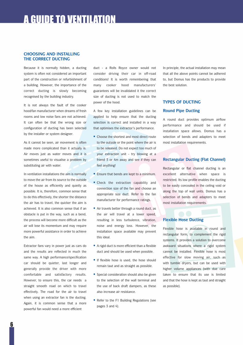
TYPES OF DUCTING
Round Pipe Ducting
A round duct provides optimum airflow
performance and should be used if
installation space allows. Domus has a
selection of bends and adapters to meet
most installation requirements.
Rectangular Ducting (Flat Channel)
Rectangular or flat channel ducting is an
excellent alternative when space is
restricted. Its low profile enables the ducting
to be easily concealed in the ceiling void or
along the top of wall units. Domus has a
selection of bends and adapters to meet
most installation requirements.
Flexible Hose Ducting
Flexible hose is available in round and
rectangular form, to complement the rigid
systems. It provides a solution to overcome
awkward situations where a rigid system
cannot be installed. Flexible hose is most
effective for slow moving air, such as
with tumble dryers, but can be used with
higher volume appliances (with due care
taken to ensure that its use is limited
and that the hose is kept as taut and straight
as possible).
A GUIDE TO VENTILATION

7
As has already been explained, the
performance of the fan is dependent on the
performance capability of the fan itself, the
size of the duct, the ducting configuration
and the type of wall terminal installed.
Each ducting run can be planned in advance
and its performance levels evaluated so it
can be ascertained if the desired installation
will meet the required level.
Technical data is available for the extractor
fan/cooker hood installer or system designer
in order to achieve the optimum overall
extraction rate. This data highlights how
much pressure (measured in Pascals) is
generated in the ducting run and will show if
the required airflow rate can be achieved.
The diagram above shows a typical pressure-
flowrate curve for an extractor fan or cooker
hood (flow rate information should be
available from the fan/cooker hood
manufacturer). The information it contains is
obtained by a series of laboratory
measurements starting with free flow at zero
pressure, then, by steadily increasing the
pressure that the fan has to operate against,
the volume flow and pressure at each point
is derived in order to plot the curve.
As detailed in the diagram, in order to
achieve the current UK Building Regulation
flow rate requirement for a kitchen of 60 l/s
(or 216 m3/hr, 30 l/s or 108 m3/hr, for a hood
within 300mm of hob centreline), the
maximum duct system resistance when using
this particular cooker hood can be no greater
than 150 Pascals (Pa). Therefore, it can be
readily seen that by reducing the resistance
of the duct system, the extract performance
of the fan or cooker hood is increased.
Furthermore, it can be stated that a ducting
system with a low resistance is a duct
system with a good performance.
The performance of a ducting system is
greatly affected by both the overall length of
the ducting, the number of bends contained
within it and the type of outlet. The total
resistance of the duct system can be
calculated by simply adding up the
resistance of each component. Each product
within the Domus range has a measured
resistance value for the three UK Building
Regulation flow rates. These figures are
detailed within the ducting system sections
of this catalogue, against each component.
Note: For every extractor fan or cooker hood
installation, provision should be made for
make-up or return air. In most dwellings this
is catered for by natural leakage. However,
some high performance products may
require the installation of an air supply set
(see page 37-38).
The following is a calculation example using
the typical ducting layout shown in the
diagram.
Therefore the airflow performance of the
cooker hood connected should exceed
39 Pa @ 30 l/s.
Within the Ducting section, in order to
encourage good practice (for guidance
only) each system is supported with an
icon depicting the application for which it
is suited.
TECHNICAL ADVICE
Domus offers expert technical advice on all
ventilation installations and has individual
dimensioned drawings available on request.
System Configuration (as kit 227)Resistance
Product Description (Pa) @ 30 l/s
2 x 510 1m Flat Channel (2 off) 3.01 x 520 Flat Channel Connector 0.41 x 541 Elbow Bend with 125mm Spigot 11.11 x 561 125mm Flexible Hose, 1m 0.7*1 x 501 Airbrick with Damper 23.8
Total 39.0
* Based on a 1m length of 125mm pipe, presuming that the hose is pulled taut.
200
150
100
50
015 30 8060
High Flowrate
Low Flowrate
Low Pressure
High Pressure
Pressure(Pa)
Flowrate (l/s)
UNDERSTANDING DUCTINGPERFORMANCE FIGURES
www.domusventilation.com
A GUIDE TO VENTILATION

THE PLEDGE OF QUALITY AND SAFETY
Domus ducting products are manufactured to the higheststandards using the latest production techniques andequipment to ensure a consistently high quality product that issafe to install.
● All Domus system parts, flat channel and pipes are madefrom flame retardant self extinguishing materials to conformto fire standards UL94 V2 and DIN 4102 B1
● Manufactured to strict quality control procedures
● Wall outlets are made with UV stabilised materials toreduce colour fade
● Airbricks meet British Standard BS493
● Non corrosive products ensure durability
● Push-fit lightweight product saves time in installation andreduces careless accidents and the need for special tools
● Robust packaging protects the products
● Domus is a member of a BS EN ISO 9002 registered group
● Products are independently tested by BSRIA for airflowperformance
The product codes throughout this catalogue
are shown as either a Boxed or Prepacked
option. This refers to the type of packaging
that the product will be supplied in.
PRODUCT CODES/PACKAGING TYPE
toilet
shower
bathroom
kitchen
utility room
whole house
ROOM LOCATIONS
ICONS
To assist in selection, icons are used
throughout this catalogue. These are used
to indicate the room that is best suited to
the particular product.
Boxed Prepacked
8
DUCTINGDUCTING

● Available with round spigots or rectangular sockets to fit all Domus ducting systems
● Various types for different applications
● External and internal options
● Choices for the wall, ceiling and roof
● Manufactured with UV stable materials to reduce colour fade
● Airbricks meet British Standard BS493
● Choice of colours
● Excellent air flow performance
● Easy to install
OUTLETS, GRILLES AND VENTILATORS
9
Domus manufacture a wide range of ventilation
terminals to either let air in or out. Wall outlets
are available with round spigots in 100, 125
and 150mm dia. or with rectangular sockets to
connect to all Domus ducting systems and fans.
Domus provide options for internal or external
use on the wall, ceiling or roof. There are
various choices for different situations.
Gravity Flap Outlets are designed to provide a
back draft barrier, but are not recommended
for use in exposed locations.
Louvred Grilles can be used internally and
externally are available with or without a
flyscreen and provide excellent airflow
performance.
Cowled Outlets supply exceptional protection
against the effects of high winds and driving
rain and include a damper flap to help reduce
back drafts.
High Rise Round Cowled Outlets save time
and money when installing on an upper floor or
in a high rise building. This outlet can be
installed from the inside out negating the need
for dangerous ladders and scaffolding.
Brick Size Outlets are designed to fit in the
wall and form part of the brick work. They can
be used internally and externally.
Air Valves for both extract and supply are
available and are particularly useful to achieve
a balanced airflow.
All are designed to provide optimum airflow
performance and for easy installation. They are
manufactured in high quality impact resistant
polystyrene. Pressure loss figures detailed in
the product listings are exhaust rates, except
in a few instances where an intake figure is
also shown.
Most are available in four colours to
complement common wall finishes and
are made with UV stable materials to reduce
colour fade.
Also available is a selection of ventilators for
doors, worktops and plinths.
B = Brown C = Beige (Cotswold Stone) T = TerracottaW = White
WALL OUTLET COLOURS

10
Product Code Description Dimensions mm Airflow Pressure loss.paBoxed Prepack Overall Fitting area mm2 15 l/s 30 l/s 60 l/s
4900 44910* Wall Outlet with Gravity Flaps
4901 44910* Wall Outlet with Gravity Flaps
4902 44932* Cowled Wall Outlet with Damper
4903 44932* Cowled Wall Outlet with Damper
4904 n/a Louvred Grille
F4904 44954* Louvred Grille with Flyscreenas intake
4905 n/a Louvred Grille
F4905 44954* Louvred Grille with Flyscreen
4994 n/a Louvred Grille with Internal Damper
154 x 154 O 100 7200 9.2 10.8 11.4 ✓† ✓‡ ✓ ✓
154 x 154 110 x 54 5770 13.2 11.0 11.8 ✓ ✓
154 x 154 O 100 7230 6.7 12.5 41.6 ✓† ✓‡ ✓ ✓
154 x 154 110 x 54 5800 6.1 16.7 68.2 ✓ ✓
154 x 154 O 100 6500 2.0 7.9 30.4 ✓† ✓‡ ✓ ✓
154 x 154 O 100 5850 9.9 37.1 138.7 ✓† ✓‡ ✓ ✓
6.7 25.6 97.1154 x 154 110 x 54 5500 4.1 15.9 61.6 ✓ ✓
154 x 154 110 x 54 4950 20.0 75.9 288.2 ✓ ✓
154 x 154 O 100 5125 19.8 36.6 96.0 ✓† ✓‡ ✓ ✓
200 x 200 O 125 11200 6.7 9.9 12.7 ✓† ✓ ✓
200 x 200 O 125 11500 5.8 7.7 13.1 ✓† ✓ ✓
200 x 200 O 125 11500 0.6 2.1 7.7 ✓† ✓ ✓
200 x 200 O 125 9200 2.0 7.1 24.6 ✓† ✓ ✓
183 x 195 O 125 6600 19.8 32.4 73.2 ✓† ✓ ✓
5900 n/a Wall Outlet with Gravity Flaps
5902 n/a Cowled Wall Outlet with Damper
5904 n/a Louvred Grille
F5904 n/a Louvred Grille with Flyscreen
500 n/a Louvred Grille with Internal Damper
100MM (4Ó) WALL OUTLETS
125MM (5Ó) WALL OUTLETSSy
stem
100
Su
pert
ube
125
Poly
Vent
225
Easi
Pipe
/The
rmaP
ipe
100
Easi
Pipe
/The
rmaP
ipe
125
100m
m R
ound
Fle
xi H
ose
125m
m R
ound
Fle
xi H
ose
100m
m R
ect.
Flex
i Hos
e
† With adapter ref. 570. See page 19 O = outer dimension
● = internal dimension O = outer dimension * Prepacks include both round spigot and rectangular socket and are only available in white and brown † With adapter ref 070. See page 16‡ With adapter ref 2005. See page 23
OUTLETS, GRILLES AND VENTILATORS

11
Product Code Description Dimensions mm Airflow Pressure loss.paBoxed Prepack Overall Fitting area mm2 15 l/s 30 l/s 60 l/s
200 x 200 O 150 16000 5.9 8.5 11.4 ✓✝ ✓ ✓
200 x 200 O 150 16500 5.3 8.0 14.5 ✓✝ ✓ ✓
200 x 200 O 150 16500 0.5 1.8 6.3 ✓✝ ✓ ✓
200 x 200 O 150 13200 1.6 5.2 17.4 ✓✝ ✓ ✓
245 x 141 227 x 133 15175 14.8 61.1 103.3 ✓‡ ✓*
227 x 133 1 227 x 133 - - - - ✓2 220 x 90 - 20.8 75.1 173.0
- - 6.28 22.1 51.8
235 x 150 227 x 133 - - - - ✓O 100O 125O 150
222 x 69 200 x 56 6450 16.4 23.8 75.8 ✓† ✓
204 x 60 204 x 60 5500 7.2 27.8 108.1 ✓† ✓
65 x 210 60 x 204 6300 5.1 21.0 80.0 ✓† ✓
204 x 60 - - 1.2 4.7 17.8 ✓
204 x 60 O 100 - 4.13 16.83 68.66 ✓ ✓
210 x 65 234 x 29 5500 7.7 29.9 115.8 ✓
210 x 65 100 5500 8.5 33.5 132.2 ✓
6900 n/a Wall Outlet with Gravity Flaps
6902 n/a Cowled Wall Outlet with Damper
6904 n/a Louvred Grille
F6904 n/a Louvred Grille with Flyscreen
905 n/a Double Airbrick
977 n/a Double Airbrick Adapter with 905 & 225mm of MegaDuct
with 905 & 1.5m of MegaDuct
954 n/a Double Airbrick Adapter to Round Pipe (100, 125 & 150mm)(complete length 260mm)
501 n/a Horizontal Louvred Airbrick withDamper
505 40505 Horizontal Louvred Airbrick507 n/a Vertical Louvred Airbrick
077 40077 Airbrick Adapter (to System 100)073 n/a Round to Single Airbrick Adapter
(length 245mm) (not shown)
2009 n/a Extended Horizontal Airbrick3009 n/a Extended Horizontal Airbrick
length 300mm
150MM (6Ó) WALL OUTLETS
Easi
Pipe
/The
rmaP
ipe
150
Meg
aDuc
t 220
150m
m R
ound
Fle
x Ho
se
† Using airbrick adapter ref. 077 = internal dimension = outer dimension * Using airbrick adapter ref. 977‡ Using adapters 977 & 957 (See page 21)
O = outer dimension† = with adapter ref. 970 and ref. 135-6 (See pages 21 and 29)
Syst
em 1
00
Supe
rtub
e 12
5
Meg
aDuc
t 220
Poly
Vent
225
BRICK SIZE OUTLETS
Poly
Vent
300
Easi
Pipe
100
/125
/150
15 l/s 30 l/s 60 l/s
Product Code Description Dimensions mm Airflow Pressure loss.paBoxed Prepack Overall Fitting area mm2 60 l/s 120 l/s 180 l/s
2
1
OUTLETS, GRILLES AND VENTILATORS
12
Product Code Description Dimensions mm Airflow Pressure loss.paBoxed Prepack Overall Fitting area mm2 15 l/s 30 l/s 60 l/s Su
pert
ube
125
Syst
em10
0
Poly
Vent
225
/300
100m
m R
ound
Duc
t/Fl
ex
125m
m R
ound
Duc
t/Fl
ex
150m
m R
ound
Duc
t/Fl
ex
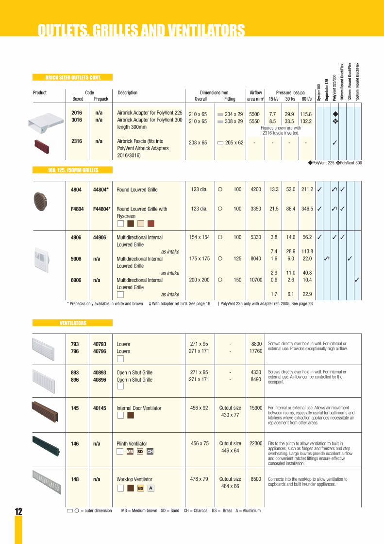
123 dia. O 100 4200 13.3 53.0 211.2 ✓ ✓† ✓
123 dia. O 100 3350 21.5 86.4 346.5 ✓ ✓† ✓
154 x 154 O 100 5330 3.8 14.6 56.2 ✓ ✓ ✓
7.4 28.9 113.8175 x 175 O 125 8040 1.6 6.0 22.0 ✓‡ ✓
2.9 11.0 40.8200 x 200 O 150 10700 0.6 2.6 10.4 ✓
1.7 6.1 22.9
271 x 95 - 8800271 x 171 - 17760
271 x 95 - 4330271 x 171 - 8490
456 x 92 Cutout size 15300430 x 77
456 x 75 Cutout size 22300446 x 64
478 x 79 Cutout size 8500464 x 66
4804 44804* Round Louvred Grille
F4804 F44804* Round Louvred Grille with Flyscreen
4906 44906 Multidirectional Internal Louvred Grille
as intake 5906 n/a Multidirectional Internal
Louvred Grilleas intake
6906 n/a Multidirectional InternalLouvred Grille
as intake
793 40793 Louvre796 40796 Louvre
893 40893 Open n Shut Grille896 40896 Open n Shut Grille
145 40145 Internal Door Ventilator
146 n/a Plinth Ventilator
148 n/a Worktop Ventilator
BRICK SIZED OUTLETS CONT.
100, 125, 150MM GRILLES
VENTILATORS
Screws directly over hole in wall. For internal orexternal use. Provides exceptionally high airflow.
Connects into the worktop to allow ventilation tocupboards and built in/under appliances.
Screws directly over hole in wall. For internal orexternal use. Airflow can be controlled by theoccupant.
For internal or external use. Allows air movementbetween rooms, especially useful for bathrooms andkitchens where extraction appliances necessitate airreplacement from other areas.
Fits to the plinth to allow ventilation to built inappliances, such as fridges and freezers and stopoverheating. Large louvres provide excellent airflowand convenient ratchet fittings ensure effectiveconcealed installation.
A
CHSDMB
BS
O = outer dimension MB = Medium brown SD = Sand CH = Charcoal BS = Brass A = Aluminium
* Prepacks only available in white and brown ‡ With adapter ref 570. See page 19 † PolyVent 225 only with adapter ref. 2005. See page 23
◆ PolyVent 225 ❖ PolyVent 300
2016 n/a Airbrick Adapter for PolyVent 2253016 n/a Airbrick Adapter for PolyVent 300
length 300mm
2316 n/a Airbrick Fascia (fits into PolyVent Airbrick Adapters 2016/3016)
210 x 65 234 x 29 5500 7.7 29.9 115.8 ◆
210 x 65 308 x 29 5550 8.5 33.5 132.2 ❖
208 x 65 205 x 62 - - - - ✓
OUTLETS, GRILLES AND VENTILATORS
Figures shown are with 2316 fascia inserted.
13
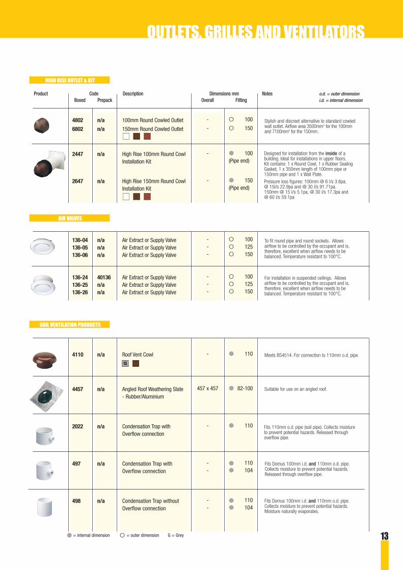
- O 100
- O 150
- ● 100(Pipe end)
- ● 150(Pipe end)
- O 100- O 125- O 150
- O 100- O 125- O 150
- ● 110
457 x 457 ● 82-100
- ● 110
- ● 110- ● 104
- ● 110- ● 104
4802 n/a 100mm Round Cowled Outlet
6802 n/a 150mm Round Cowled Outlet
2447 n/a High Rise 100mm Round Cowl Installation Kit
2647 n/a High Rise 150mm Round Cowl Installation Kit
136-04 n/a Air Extract or Supply Valve136-05 n/a Air Extract or Supply Valve136-06 n/a Air Extract or Supply Valve
136-24 40136 Air Extract or Supply Valve136-25 n/a Air Extract or Supply Valve136-26 n/a Air Extract or Supply Valve
4110 n/a Roof Vent Cowl
4457 n/a Angled Roof Weathering Slate- Rubber/Aluminium
2022 n/a Condensation Trap withOverflow connection
497 n/a Condensation Trap with Overflow connection
498 n/a Condensation Trap without Overflow connection
Product Code Description Dimensions mm Notes o.d. = outer dimensionBoxed Prepack Overall Fitting i.d. = internal dimension
HIGH RISE OUTLET & KIT
AIR VALVES
SOIL VENTILATION PRODUCTS
● = internal dimension O = outer dimension G = Grey
Meets BS4514. For connection to 110mm o.d. pipe.
Suitable for use on an angled roof.
Fits Domus 100mm i.d. and 110mm o.d. pipe.Collects moisture to prevent potential hazards.Released through overflow pipe.
Fits 110mm o.d. pipe (soil pipe). Collects moistureto prevent potential hazards. Released throughoverflow pipe.
Fits Domus 100mm i.d. and 110mm o.d. pipe.Collects moisture to prevent potential hazards.Moisture naturally evaporates.
To fit round pipe and round sockets. Allowsairflow to be controlled by the occupant and is,therefore, excellent when airflow needs to bebalanced. Temperature resistant to 100°C.
Stylish and discreet alternative to standard cowledwall outlet. Airflow area 3500mm2 for the 100mmand 7100mm2 for the 150mm.
Designed for installation from the inside of abuilding. Ideal for installations in upper floors.Kit contains: 1 x Round Cowl, 1 x Rubber SealingGasket, 1 x 350mm length of 100mm pipe or150mm pipe and 1 x Wall Plate.
Pressure loss figures: 100mm @ 6 l/s 3.6pa,@ 15l/s 22.9pa and @ 30 l/s 91.71pa.150mm @ 15 l/s 5.1pa, @ 30 l/s 17.3pa and @ 60 l/s 59.1pa
For installation in suspended ceilings. Allowsairflow to be controlled by the occupant and is,therefore, excellent when airflow needs to bebalanced. Temperature resistant to 100°C.
OUTLETS, GRILLES AND VENTILATORS
G

14
System 100 is a rectangular range of ducting
that is efficient for short simple runs. It is
particularly suitable for applications requiring
lower extraction rates, such as, the ventilation of
domestic bathrooms and internal WCs.
The low profile of the design enables it to be
concealed when installed along the top of wall
units or when fitted in ceiling voids, cavity walls
and other confined spaces, providing versatility
but remaining unobtrusive.
Bends, connectors, adapters and clips ensure
that System 100 offers the installer the flexibility
to achieve almost any ducting configuration and
the ability to connect to other Domus systems.
● Recommended for domestic bathrooms, WCs andkitchens with low volume extraction of up to 250 m3/hr
● Efficient for short, simple ducting runs
● Low profile enables ducting to be easily concealedwhen space is a restriction
● Made from self extinguishing flame retardant materials to conform to fire standards UL94 V2 and DIN 4102 B1
● Maximum working temperature of 60ºC
● A wide range of bends and adapters enables versatileinstallation
● Compatible with a large selection of outlets and inlets and other Domus ducting systems
● Also available prepacked
54mm
110mm
115mm
60mm
DIMENSIONS
All measurements in mm. Drawings not to scale.
System 100Flat channel outerdimensions are 110 x 54mm and fit into system partssockets
Minimum space required for installation:115 x 60mm
SYSTEM 100
Cross section:5300 sq mm

15
SYSTEM 100
Product Code Description Dimensions Pressure loss.pa Notes i.d. = internal dimensionBoxed Prepack mm 15 l/s 30 l/s 60 l/s o.d. = outer dimension
110 x 54 1.8 6.3 21.5110 x 54 2.7 9.75 32.25110 x 54 3.6 12.6 43.0
110 x 54 1.8 6.3 21.5
112 x 60
110 x 54 - - -
110 x 54 0.3 1.4 6.3
110 x 54 19.9 21.2 16.9
110 x 54 8.1 33.1 136.4● 100
110 x 54 8.1 33.1 136.4O 100
110 x 54 9.8 39.8 161.9
110 x 54 15.6 62.8 252.7
110 x 54
010 40010 Flat Channel, 1m015 n/a Flat Channel, 1.5mD1-2000 n/a Flat Channel, 2m
D2-1000 n/a Flat Channel Outer Sleeve, 1m
122-4 40122* Flat Channel Clip
020 40020 Flat Channel Connector
027 n/a Flat Channel Connectorwith Damper
030 40030 Elbow Bend with Socket
040 40040 Elbow Bend with Spigot
050 40050 Horizontal 90° Bend
060 40060 Vertical 90° Bend
080 40080 Horizontal Equal T-Piece
Connects into components withrectangular sockets (110 x 54mmi.d.) e.g. System 100 bends.
Fits over flat channel to provide atelescopic assembly.
Securely fixes flat channel todesired location e.g. ceiling or wallunit.
Fits over flat channel to connecttwo lengths together in a straightline.
Fits over flat channel to connecttwo lengths together in a straightline. Includes damper for back draftprevention.
Fits over flat channel to connectchannel to round flexible hose withthreaded hose connector (124-4) atright angles or fits directly over a100mm o.d. appliance spigot.
Fits over flat channel to connectchannel to round flexible hose withhose clip (125-4) at right angles ordirectly into EasiPipe 100 (100mmi.d. connections).
Fits over flat channel to connecttwo lengths together horizontally atright angles.
Fits over flat channel to connecttwo lengths together vertically atright angles.
Fits over flat channel to provide arectangular ducting junction in amulti-extraction installation.
* 2 items in prepack ● = internal dimension O = outer dimension
Figures vary on installation
up to 250 m3/hr
Please refer to pages 9-13 forWall Outlets for this range
Ducting through a compartment wall?Take a look at FireBrake on pages 47-50 and preventthe spread of fire through ventilation ducting.

16
Product Code Description Dimensions Pressure loss.pa Notes i.d. = internal dimension
Boxed Prepack mm 15 l/s 30 l/s 60 l/s o.d. = outer dimension
110 x 54 3.7 14.6 58● 100
110 x 54 4.8 20.4 86.2O 100
204 x 60 1.2** 4.7** 17.8**
110 x 54 - - -154 x154
108 x 52 - - -110 x 54
070 40070 Round to Rectangular Adapter
071 40071 Short Round to Rectangular Adapter
077 40077 Airbrick Adapter and converter to Supertube 125
115-4 40115 Flat Channel Wall Plate
018 n/a Flat Channel End Cap
Fits over flat channel to connectin a straight line to fit over a100mm o.d. spigot e.g. walloutlet/cooker hood or fan spigotor to EasiPipe 100 via a straightpipe connector (493/4/5). Pipeand channel lay flush to surface.
Fits over flat channel to connectin a straight line to fit into100mm i.d. connections,including EasiPipe 100 pipes.Channels lay in a centralposition.
Connects into System 100 flatchannel to adapt to Supertube125 flat channel, by fitting overa Supertube 125 flat channelconnector (520 or 527). Fits all Supertube 125 sockets(204 x 60mm i.d. connections).
Fits over flat channel to makegood internal wall after formingrectangular hole for ducting.
Fits into flat channel to blank offend.
**Figures going from Supertube 125 to System 100. See other sections for performance figures using this item with other components● = internal dimension O = outer dimension
SYSTEM 100
Please refer to pages 9-13 forWall Outlets for this range
Ducting through a compartment wall?Take a look at FireBrake on pages 47-50 and preventthe spread of fire through ventilation ducting.
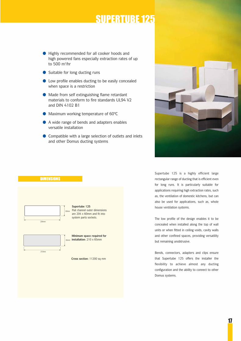
● Highly recommended for all cooker hoods and high powered fans especially extraction rates of up to 500 m3/hr
● Suitable for long ducting runs
● Low profile enables ducting to be easily concealed when space is a restriction
● Made from self extinguishing flame retardant materials to conform to fire standards UL94 V2 and DIN 4102 B1
● Maximum working temperature of 60ºC
● A wide range of bends and adapters enables versatile installation
● Compatible with a large selection of outlets and inlets and other Domus ducting systems
Supertube 125 is a highly efficient large
rectangular range of ducting that is efficient even
for long runs. It is particularly suitable for
applications requiring high extraction rates, such
as, the ventilation of domestic kitchens, but can
also be used for applications, such as, whole
house ventilation systems.
The low profile of the design enables it to be
concealed when installed along the top of wall
units or when fitted in ceiling voids, cavity walls
and other confined spaces, providing versatility
but remaining unobtrusive.
Bends, connectors, adapters and clips ensure
that Supertube 125 offers the installer the
flexibility to achieve almost any ducting
configuration and the ability to connect to other
Domus systems.
Supertube 125Flat channel outer dimensionsare 204 x 60mm and fit intosystem parts sockets.
Minimum space required forinstallation: 210 x 65mm
Cross section: 11200 sq mm
DIMENSIONS
SUPERTUBE 125
60mm
204mm
65mm
210mm
17

18
Product Code Description Dimensions Pressure loss.pa Notes i.d. = internal dimension
Boxed Prepack mm 15 l/s 30 l/s 60 l/s o.d. = outer dimension
204 x 60 0.5 1.5 5.2204 x 60 0.75 2.25 7.8204 x 60 1.0 3.0 10.4
204 x 60 - - -
204 x 60 0.1 0.4 1.5
204 x 60 21.9 41.1 43.2
204 x 60 7.3 29.1 116.4O 100
204 x 60 2.7 11.1 45.9O 125
204 x 60 1.1 4.5 18.3O 150
● 125 - - -● 100
204 x 60 2.1 8.4 33.7
204 x 60 0.7 2.1 6.3204 x 60
510 n/a Flat Channel, 1m515 n/a Flat Channel, 1.5mD3-2000 n/a Flat Channel, 2m
122-5 n/a Flat Channel Clip
520 n/a Flat Channel Connector
527 n/a Flat Channel Connectorwith Damper
441 n/a Elbow Bend with 100mm o.d.Rotating Offset Spigot
541 n/a Elbow Bend with 125mm o.d.Rotating Offset Spigot
641 n/a Elbow Bend with 150mm o.d.Rotating Offset Spigot
544 n/a Adapter from 125mm to 100mm
550 n/a Horizontal 90° Bend
545 n/a Adjustable Horizontal Bend
Connects into components withrectangular sockets (204 x 60mmi.d.) e.g. Supertube 125 bends.
Securely fixes flat channel todesired location e.g. ceiling or wallunit.
Fits over flat channel to connecttwo lengths together in a straightline.
Fits over flat channel to connecttwo lengths together in a straightline. Includes damper for back draftprevention.
Fits over flat channel to connectchannel to round flexible hose withthreaded hose connector (126-4) orhose clip (125-4) at right angles orfits directly over a 100mm o.d.appliance spigot or EasiPipe 100.
Fits over flat channel to connectchannel to round flexible hose withthreaded hose connector (126-5) or hose clip (125-5) at right anglesor fits directly into Easipipe 125(125mm i.d. connections) orEasiPipe 125.
Fits over flat channel to connectchannel to round flexible hose withthreaded hose connector (126-6) or hose clip (125-6) at right anglesor fits directly into Easipipe 150(150mm i.d. connections) orEasiPipe 150.
Adapts 125mm ducting to 100mmappliance spigots, eg fits overthreaded hose connector (126-5) toconnect to spigot on cooker hood.
Fits over flat channel to connecttwo lengths together horizontally at right angles.
Connects two lengths of flatchannel together horizontally bycutting to desired angle. Channelfits into normal end and overadjustable end.
● = internal dimension O = outer dimension
up to 500 m3/hr
SUPERTUBE 125
Please refer to pages 9-13 forWall Outlets for this range
Ducting through a compartment wall?Take a look at FireBrake on pages 47-50 and preventthe spread of fire through ventilation ducting.

19
Product Code Description Dimensions Pressure loss.pa Notes i.d. = internal dimensionBoxed Prepack mm 15 l/s 30 l/s 60 l/s o.d. = outer dimension
204 x 60 2.6 10.8 44.3
204 x 60
204 x 60 0.7 2.9 11.5● 125
204 x 60 - - -264 x119
200 x 56 - - -204 x 60
Fits over flat channel to connecttwo lengths together vertically atright angles.
Fits over flat channel to provide arectangular ducting junction in amulti-extraction installation.
Fits over flat channel to connect ina straight line to fit over a 125mmo.d. spigot e.g. wall outlet/cookerhood or fan spigot or to EasiPipe125 via a straight pipe connector(595/4/5). Pipe lays flush to surface.
Used to make good internal wallafter forming rectangular hole forducting or as surround for airbrick(501 only)
Fits into flat channel to blank offend.
560 n/a Vertical 90° Bend
582 n/a Horizontal Equal T-Piece
570 n/a Round to Rectangular Adapter220mm length
115-5 n/a Rectangular Wall Plate
518 n/a Flat Channel End cap
● = internal dimension O = outer dimension
Figures vary on installation
SUPERTUBE 125
Please refer to pages 9-13 forWall Outlets for this range
Ducting through a compartment wall?Take a look at FireBrake on pages 47-50 and preventthe spread of fire through ventilation ducting.

20
DIMENSIONS
MEGADUCT 220
MegaDuct 220Flat channel outer dimensions are 220 x 90mm and fit into system parts sockets
Minimum space required for installation: 227 x 97mm
Cross section: 17798mm2
220mm
227mm
90mm
97mm
The large capacity of MegaDuct 220 ensures
that it can cope with the air volume generated
by the high extraction rates of the new stylish
cooker hoods now on the market. Unwanted
air and smells can be removed effectively and
efficiently. It is a case of duct and hood in
perfect harmony. The benefits of MegaDuct
220 are an improved living environment and
quieter, less overworked and longer-lasting
cooker hoods.
MegaDuct 220 is the next generation
of ducting and, as kitchen manufacturers,
hood manufacturers, builders and designers
begin to work together it will soon become
the norm.
The low profile of MegaDuct 220 makes it
easier to conceal than an equivalent 150mm
round duct. This makes it more suitable for
installation along the top of wall units or
fitting in ceiling voids and other confined
spaces.
Bends, connectors and adapters ensure
MegaDuct 220 offers the installer the
flexibility to achieve almost any ducting
configuration and the ability to connect to
other Domus systems.
● Highly recommended for the ducting of all cooker hoods even the latest high powered hoods that can exceed extraction rates of 1000m3/hr
● Suitable for long ducting runs
● Easier to conceal than an equivalent 150mm round duct
● Made from self-extinguishing flame-retardant materials to conform to fire standards UL94 V2 and DIN 4102 B1
● Maximum working temperature of 60°C
● A wide range of bends enables versatile installation
● Compatible with a selection of outlets and inlets andother Domus Ducting systems
21
Product Code Description Dimensions Pressure loss.pa Notes i.d. = internal dimension
Boxed Prepack mm 60 l/s 120 l/s 180 l/s o.d. = outer dimension
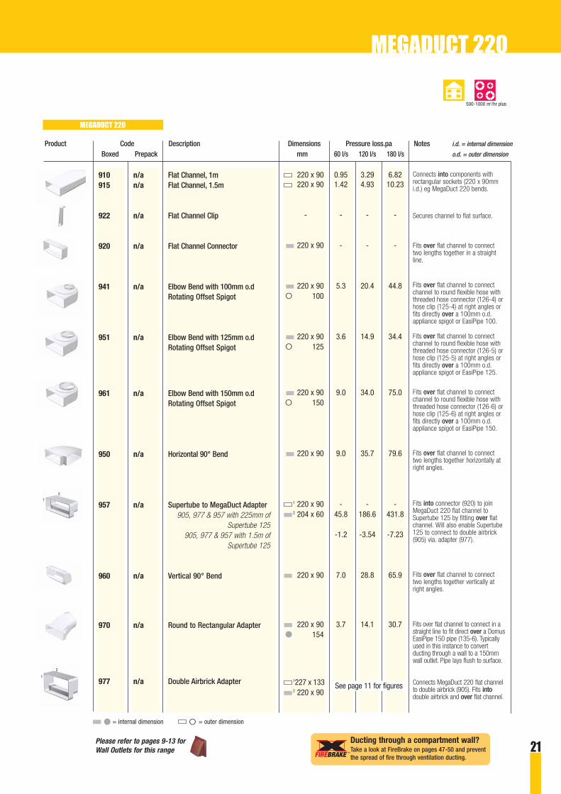
220 x 90 0.95 3.29 6.82220 x 90 1.42 4.93 10.23
- - - -
220 x 90 - - -
220 x 90 5.3 20.4 44.8O 100
220 x 90 3.6 14.9 34.4O 125
220 x 90 9.0 34.0 75.0O 150
220 x 90 9.0 35.7 79.6
1 220 x 90 - - -2 204 x 60 45.8 186.6 431.8
-1.2 -3.54 -7.23
220 x 90 7.0 28.8 65.9
220 x 90 3.7 14.1 30.7● 154
1227 x 1332 220 x 90
910 n/a Flat Channel, 1m915 n/a Flat Channel, 1.5m
922 n/a Flat Channel Clip
920 n/a Flat Channel Connector
941 n/a Elbow Bend with 100mm o.dRotating Offset Spigot
951 n/a Elbow Bend with 125mm o.dRotating Offset Spigot
961 n/a Elbow Bend with 150mm o.dRotating Offset Spigot
950 n/a Horizontal 90° Bend
957 n/a Supertube to MegaDuct Adapter905, 977 & 957 with 225mm of
Supertube 125 905, 977 & 957 with 1.5m of
Supertube 125
960 n/a Vertical 90° Bend
970 n/a Round to Rectangular Adapter
977 n/a Double Airbrick Adapter
Connects into components withrectangular sockets (220 x 90mmi.d.) eg MegaDuct 220 bends.
Fits over flat channel to connecttwo lengths together in a straightline.
Secures channel to flat surface.
Fits over flat channel to connectchannel to round flexible hose withthreaded hose connector (126-4) orhose clip (125-4) at right angles orfits directly over a 100mm o.d.appliance spigot or EasiPipe 100.
Fits over flat channel to connectchannel to round flexible hose withthreaded hose connector (126-5) orhose clip (125-5) at right angles orfits directly over a 100mm o.d.appliance spigot or EasiPipe 125.
Fits over flat channel to connectchannel to round flexible hose withthreaded hose connector (126-6) orhose clip (125-6) at right angles orfits directly over a 100mm o.d.appliance spigot or EasiPipe 150.
Fits over flat channel to connecttwo lengths together horizontally atright angles.
Fits into connector (920) to joinMegaDuct 220 flat channel toSupertube 125 by fitting over flatchannel. Will also enable Supertube125 to connect to double airbrick(905) via. adapter (977).
Fits over flat channel to connecttwo lengths together vertically atright angles.
Fits over flat channel to connect in astraight line to fit direct over a DomusEasiPipe 150 pipe (135-6). Typicallyused in this instance to convertducting through a wall to a 150mmwall outlet. Pipe lays flush to surface.
Connects MegaDuct 220 flat channelto double airbrick (905). Fits intodouble airbrick and over flat channel.
● = internal dimension O = outer dimension
MEGADUCT 220
MEGADUCT 220
500-1000 m3/hr plus
2
1
1
2
See page 11 for figures
Please refer to pages 9-13 forWall Outlets for this range
Ducting through a compartment wall?Take a look at FireBrake on pages 47-50 and preventthe spread of fire through ventilation ducting.

22
● Recommended for the ducting of bathrooms, WCs and kitchens if other systems cannot be installed.
● Extra low profile enables ducting to be easilyconcealed when space is very restricted (where there is a void space of 38mm)
● Ideal for installation in flats or under floors
● Available in two sizes
● Made from self extinguishing flame retardant materials to conform to fire standards UL94 V2 and DIN 4102 B1
● Maximum working temperature of 60º C
● A wide range of bends and adapters enables versatile installation
● Compatible with a selection of outlets
PolyVent is a range of rectangular ducting
available in two sizes that provides effective
ventilation for bathrooms, WCs and kitchens.
It is particularly suitable for use where space
is very restricted and other systems cannot
be fitted.
The low profile of the design enables it to be
concealed when installed along the top of wall
units or when fitted in ceiling voids, cavity
walls and other confined spaces, providing
versatility but remaining unobtrusive.
PolyVent 225 is particularly suitable for short
runs with low volume extraction applications
while PolyVent 300 is recommended for
longer runs with more powerful fans or cooker
hoods up to 250 m3/hr).
Bends, connectors, adapters and clips ensure
that PolyVent offers the installer the flexibility
to achieve almost any ducting configuration
POLYVENT
PolyVent 225Flat channel outerdimensions are 234 x 29mmand fit directly into systemparts sockets to createducting runs.
Minimum space required forinstallation: 240 x 38mm
Cross section: 5830 sq mm
PolyVent 300Flat channel outerdimensions are 308 x 29mmand fit directly into systemparts sockets to createducting runs.
Minimum space required forinstallation: 315 x 38mm
Cross section: 7760 sq mm
DIMENSIONS
29mm
38mm
234mm
240mm
29mm
38mm
308mm
315mm

23
POLYVENT
Product Code Description Dimensions Pressure loss.pa Notes i.d. = internal dimension
Boxed Prepack mm 15 l/s 30 l/s 60 l/s o.d. = outer dimension
234 x 29 4.8 16.5 57.1234 x 29 7.2 24.8 85.7234 x 29 9.6 33 114.2
234 x 29
234 x 29 10 37.3 139.1
234 x 29 1.21 4.81 19.08
234 x 29 5.45 19.91 72.7
234 x 29 4.49 8.59 29.67
234 x 29 7.9 31.5 126● 100
234 x 29 3.8 14.8 57.2● 100
- - - -
2001 n/a Flat Channel, 1m20150 n/a Flat Channel, 1.5m20200 n/a Flat Channel, 2m
2006 n/a Flat Channel Connector
2007 n/a Horizontal 90° Bend
2008 n/a Horizontal 45° Bend
2010 n/a Vertical 90° Bend
2011 n/a Vertical 45° Bend
2013 n/a Elbow Bend/Plenumwith Socket
2005 n/a Round to Rectangular Adapter
2014 n/a Universal Support Clip
Connects into components withrectangular sockets (234 x 29mmi.d.) to create ducting runs.
Fits over flat channel to connecttwo lengths together in a straightline.
Fits over flat channel to connecttwo lengths together horizontally at right angles.
Fits over flat channel to connecttwo lengths together horizontally at 45°.
Fits over flat channel to connecttwo lengths together vertically at right angles.
Fits over flat channel to connecttwo lengths together vertically at 45°.
Fits over flat channel to connectround flexible hose with threadedhose connector (124-4) at rightangles or to fit directly over a100mm o.d. appliance spigot.Alternatively connects to Domus100mm i.d. pipe using straight pipeconnector (493/4/5) or adapter(380) - see EasiPipe section.
Fits over flat channel to connect ina straight line to a 100mm o.d.spigot e.g. wall outlet/cooker hoodor fan spigot or to EasiPipe 100 viaa straight pipe connector (493/4/5)or adapter (380) - see EasiPipesection. Pipe and channel lay flushto surface.
Secures channel to flat surface.Can be used with PolyVent225/300.
● = internal dimension O = outer dimension
No discernible resistance
POLYVENT 225
Please refer to pages 9-13 forWall Outlets for this range
Ducting through a compartment wall?Take a look at FireBrake on pages 47-50 and preventthe spread of fire through ventilation ducting.
24
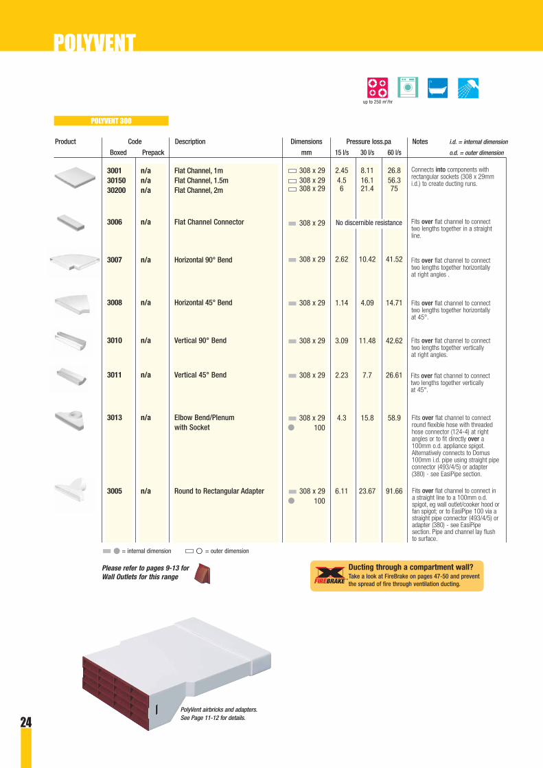
Product Code Description Dimensions Pressure loss.pa Notes i.d. = internal dimension
Boxed Prepack mm 15 l/s 30 l/s 60 l/s o.d. = outer dimension
308 x 29 2.45 8.11 26.8308 x 29 4.5 16.1 56.3308 x 29 6 21.4 75
308 x 29
308 x 29 2.62 10.42 41.52
308 x 29 1.14 4.09 14.71
308 x 29 3.09 11.48 42.62
308 x 29 2.23 7.7 26.61
308 x 29 4.3 15.8 58.9● 100
308 x 29 6.11 23.67 91.66● 100
3001 n/a Flat Channel, 1m30150 n/a Flat Channel, 1.5m30200 n/a Flat Channel, 2m
3006 n/a Flat Channel Connector
3007 n/a Horizontal 90° Bend
3008 n/a Horizontal 45° Bend
3010 n/a Vertical 90° Bend
3011 n/a Vertical 45° Bend
3013 n/a Elbow Bend/Plenumwith Socket
3005 n/a Round to Rectangular Adapter
Connects into components withrectangular sockets (308 x 29mmi.d.) to create ducting runs.
Fits over flat channel to connecttwo lengths together in a straightline.
Fits over flat channel to connecttwo lengths together horizontally at right angles .
Fits over flat channel to connecttwo lengths together horizontally at 45°.
Fits over flat channel to connecttwo lengths together vertically at right angles.
Fits over flat channel to connecttwo lengths together vertically at 45°.
Fits over flat channel to connect ina straight line to a 100mm o.d.spigot, eg wall outlet/cooker hood orfan spigot; or to EasiPipe 100 via astraight pipe connector (493/4/5) oradapter (380) - see EasiPipesection. Pipe and channel lay flushto surface.
POLYVENT
PolyVent airbricks and adapters. See Page 11-12 for details.
No discernible resistance
POLYVENT 300
up to 250 m3/hr
● = internal dimension O = outer dimension
Please refer to pages 9-13 forWall Outlets for this range
Ducting through a compartment wall?Take a look at FireBrake on pages 47-50 and preventthe spread of fire through ventilation ducting.
Fits over flat channel to connectround flexible hose with threadedhose connector (124-4) at rightangles or to fit directly over a100mm o.d. appliance spigot.Alternatively connects to Domus100mm i.d. pipe using straight pipeconnector (493/4/5) or adapter(380) - see EasiPipe section.
1.66mm approx
100mm
125mm
1.66mm approx
150mm
1.75mm approx
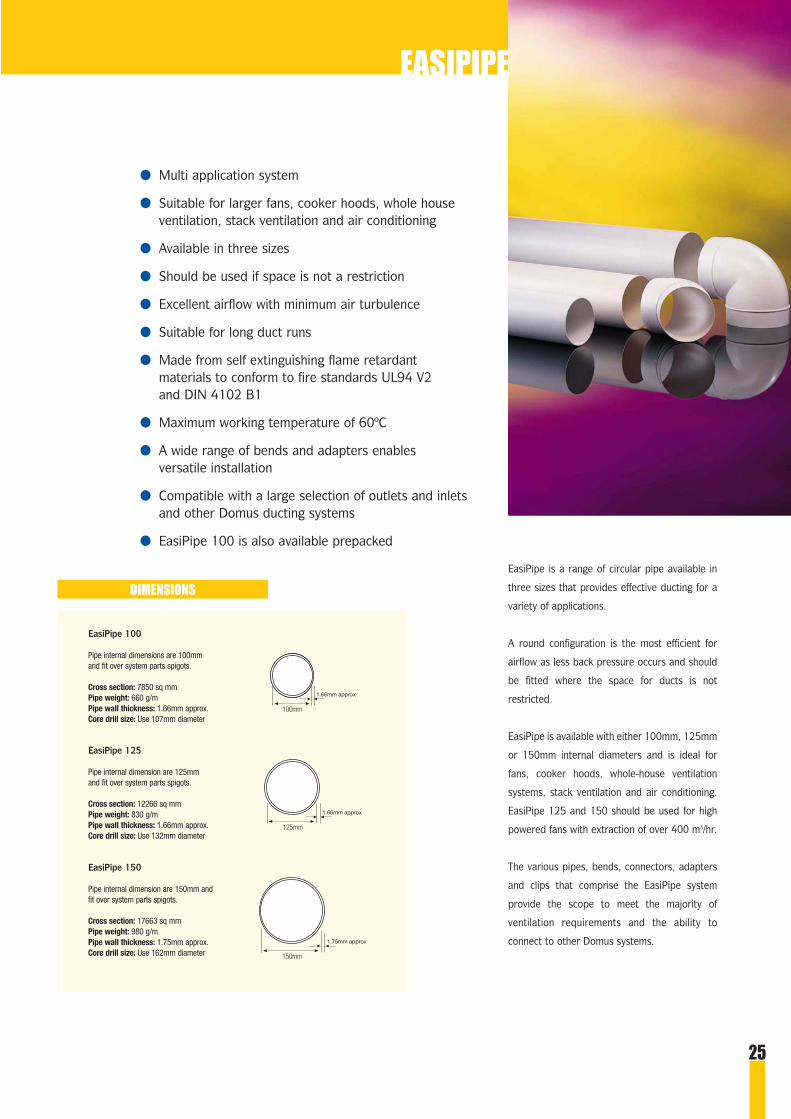
● Multi application system
● Suitable for larger fans, cooker hoods, whole houseventilation, stack ventilation and air conditioning
● Available in three sizes
● Should be used if space is not a restriction
● Excellent airflow with minimum air turbulence
● Suitable for long duct runs
● Made from self extinguishing flame retardant materials to conform to fire standards UL94 V2 and DIN 4102 B1
● Maximum working temperature of 60ºC
● A wide range of bends and adapters enables versatile installation
● Compatible with a large selection of outlets and inletsand other Domus ducting systems
● EasiPipe 100 is also available prepacked
EasiPipe is a range of circular pipe available in
three sizes that provides effective ducting for a
variety of applications.
A round configuration is the most efficient for
airflow as less back pressure occurs and should
be fitted where the space for ducts is not
restricted.
EasiPipe is available with either 100mm, 125mm
or 150mm internal diameters and is ideal for
fans, cooker hoods, whole-house ventilation
systems, stack ventilation and air conditioning.
EasiPipe 125 and 150 should be used for high
powered fans with extraction of over 400 m3/hr.
The various pipes, bends, connectors, adapters
and clips that comprise the EasiPipe system
provide the scope to meet the majority of
ventilation requirements and the ability to
connect to other Domus systems.
EASIPIPE
EasiPipe 150
Pipe internal dimension are 150mm andfit over system parts spigots.
Cross section: 17663 sq mmPipe weight: 980 g/mPipe wall thickness: 1.75mm approx.Core drill size: Use 162mm diameter
EasiPipe 125
Pipe internal dimension are 125mmand fit over system parts spigots.
Cross section: 12266 sq mmPipe weight: 830 g/mPipe wall thickness: 1.66mm approx.Core drill size: Use 132mm diameter
EasiPipe 100
Pipe internal dimensions are 100mmand fit over system parts spigots.
Cross section: 7850 sq mmPipe weight: 660 g/mPipe wall thickness: 1.66mm approx.Core drill size: Use 107mm diameter
DIMENSIONS
25

26
Fastens over Easipipe 100 tosecure pipe to the wall, ceiling orjoists in a horizontal or verticalposition.
Product Code Description Dimensions Pressure loss.pa Notes i.d. = internal dimensionBoxed Prepack mm 15 l/s 30 l/s 60 l/s o.d. = outer dimension
● 100 0.17 0.5 1.1● 100 0.5 1.4 3.1● 100 1 2.8 6.2
O 104 0.5 1.4 3.1
Inner pipe● 100Outer pipeO 104
O 100 - - -
O 100 5.6 21.1 80.1
O 100 2.1 8.2 31.4
O 100
O 100
O 100 0.9 4.2 20.4
O 100 25 44.9 101.6
O 100 25 44.9 101.6
- - - -
Fits over components with 100mmo.d. round spigots e.g. 490, 491,492, 493/4/5, wall outlets andcooker hoods.
Fits over standard round pipe tocreate a telescopic assembly.
Adjustable between 250-450mm.Includes reducing ring so that bothends have 100mm i.d. to fit overcomponents with 100mm o.d.Recommended for ducting throughcavity walls.
Fits into 100mm i.d. round pipe tomake connections to sockets with100mm i.d.
Fits into 100mm i.d. round pipe toconnect two lengths together at90°.
Fits into 100mm i.d. round pipe toconnect two lengths together at45°.
Fits into 100mm i.d. round pipe toprovide a round ducting junction ina multi-extraction installation.
Fits into 100mm i.d. round pipe toconnect two lengths together in astraight line.
Fits into 100mm i.d. round pipe toconnect two lengths together in astraight line. Includes damper forback draft prevention.
Fits into 100mm i.d. round pipe toconnect two lengths together in astraight line. Includes damper forback draft prevention and integralwall plate.
135-4 40135 Standard Round Pipe, 350mm1100-4 41100 Standard Round Pipe, 1m1200-4 n/a Standard Round Pipe, 2m
2100-4 n/a Round Pipe Outer Sleeve, 1m
130-4 n/a Telescopic Assembly, 250-450mm
380 n/a Adapter to Round Socket
490 40490 90° Bend
491 40491 45° Bend
492 40492 Equal T-Piece
499M n/a Equal Y-Piece, metal (not shown)
493 40493 Straight Pipe Connector
494 40494 Straight Pipe Connectorwith Damper
495 n/a Straight Pipe Connectorwith Damper and Wall Plate
496 40496** Pipe Fastener
● = internal dimension O = outer dimension
Figures vary according to length required
Figures vary on installation
Figures vary on installation
EASIPIPE 100
up to 400 m3/hr
Please refer to pages 9-13 forWall Outlets for this range
EASIPIPE
27
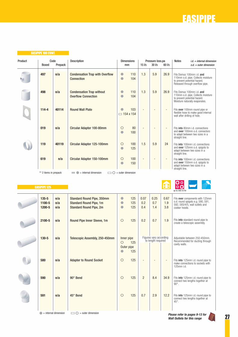
Product Code Description Dimensions Pressure loss.pa Notes i.d. = internal dimensionBoxed Prepack mm 15 l/s 30 l/s 60 l/s o.d. = outer dimension
Fits Domus 100mm i.d. and110mm o.d. pipe. Collects moistureto prevent potential hazard.Released through overflow pipe.
Fits Domus 100mm i.d. and110mm o.d. pipe. Collects moistureto prevent potential hazard.Moisture naturally evaporates.
Fits over 100mm round pipe orflexible hose to make good internalwall after drilling of hole.
Fits into 100mm i.d. connectionsand over 125mm o.d. spigots toadapt between two sizes in astraight line.
Fits into 80mm i.d. connectionsand over 100mm o.d. connectorsto adapt between two sizes in astraight line.
Fits into 100mm i.d. connectionsand over 150mm o.d. spigots toadapt between two sizes in astraight line.
497 n/a Condensation Trap with OverflowConnection
498 n/a Condensation Trap without Overflow Connection
114-4 40114 Round Wall Plate
019 n/a Circular Adapter 100-80mm
119 40119 Circular Adapter 125-100mm
619 n/a Circular Adapter 150-100mm
135-5 n/a Standard Round Pipe, 350mm1100-5 n/a Standard Round Pipe, 1m1200-5 n/a Standard Round Pipe, 2m
2100-5 n/a Round Pipe Inner Sleeve, 1m
130-5 n/a Telescopic Assembly, 250-450mm
580 n/a Adapter to Round Socket
590 n/a 90° Bend
591 n/a 45° Bend
Fits over components with 125mmo.d. round spigots e.g. 590, 591,592, 593/4/5, wall outlets andcooker hoods.
Fits into standard round pipe tocreate a telescopic assembly.
Adjustable between 250-450mm.Recommended for ducting throughcavity walls.
Fits into 125mm i.d. round pipe tomake connections to sockets with125mm i.d.
Fits into 125mm i.d. round pipe toconnect two lengths together at90°.
Fits into 125mm i.d. round pipe toconnect two lengths together at45°.
● = internal dimension O = outer dimension
● 110 1.3 5.9 26.9● 104
● 110 1.3 5.9 26.9● 104
● 103 - - -154 x 154
O 80 - - -● 100
O 100 1.5 5.9 24● 125
O 100 - - -● 150
● 125 0.07 0.25 0.67● 125 0.2 0.7 1.9● 125 0.4 1.4 3.8
O 125 0.2 0.7 1.9
Inner pipeO 125Outer pipe● 125
O 125 - - -
O 125 2 8.4 34.9
O 125 0.7 2.9 12.2
** 2 items in prepack ● = internal dimension O = outer dimension
Figures vary according to length required
EASIPIPE 100 CONT.
EASIPIPE 125up to 500 m3/hr
Please refer to pages 9-13 forWall Outlets for this range
EASIPIPE

28
Product Code Description Dimensions Pressure loss.pa Notes i.d. = internal dimensionBoxed Prepack mm 15 l/s 30 l/s 60 l/s o.d. = outer dimension
O 125
O 125
O 125 0.2 0.9 4.3
O 125 18.3 31.5 61.7
O 125 18.3 31.5 61.7
- - - -
● 128 - - -170 x 170
O 100 1.5 5.9 24● 125
O 125 0.6 2.2 8.8● 150
- - - -
592 n/a Equal T-Piece
599M n/a Equal Y-Piece, metal (not shown)
593 n/a Straight Pipe Connector
594 n/a Straight Pipe Connectorwith Damper
595 n/a Straight Pipe Connectorwith Damper and Wall Plate
596 n/a Pipe Fastener
114-5 n/a Round Wall Plate
119 40119 Circular Adapter 125-100mm
118 n/a Circular Adapter 150-125mm
519 n/a Rubber Spigot Adapter 120-125mm
Fits into 125mm i.d. round pipe toprovide a round ducting junction ina multi-extraction installation.
Fits into 125mm i.d. round pipe toconnect two lengths together in astraight line.
Fits into 125mm i.d. round pipe toconnect two lengths together in astraight line. Includes damper forback draft prevention.
Fits into 125mm i.d. round pipe toconnect two lengths together in astraight line. Includes damper forback draft prevention and integralwall plate.
Fastens over Easipipe 125 tosecure pipe to the wall, ceiling orjoists in a horizontal or verticalposition.
Fits over 125mm i.d. round pipe orflexible hose to make good internalwall after drilling of hole.
Fits into 100mm i.d. connectionsand over 125mm o.d. spigots toadapt between two sizes in astraight line.
Fits into 125mm i.d. connectionsand over 150mm o.d. spigots toadapt between two sizes in astraight line.
Adapts 115 - 122mm o.d.spigots to 125mm round ducting connections. Ideal forcooker hoods.
● = internal dimension O = outer dimension
The solution to create an effective, simple and airtight fit whenconnecting 115 - 122mm spigots to 125mm ducting systems.
Many cooker hoods have spigots between 115 - 122mm and, to ensureefficient airflow performance, they must use 125mm ducting. The ‘519’enables this to be done without the use of excessive padding, taping orjust having a loose fit, which causes air leakage.
Figures vary on installation
Figures vary on installation
EASIPIPE 125 CONT.
EASIPIPE
Please refer to pages 9-13 forWall Outlets for this range
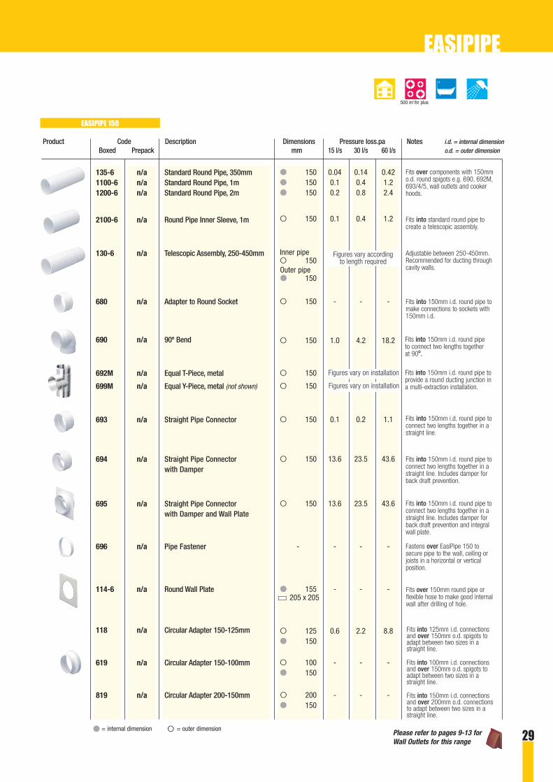
Product Code Description Dimensions Pressure loss.pa Notes i.d. = internal dimensionBoxed Prepack mm 15 l/s 30 l/s 60 l/s o.d. = outer dimension
● 150 0.04 0.14 0.42● 150 0.1 0.4 1.2● 150 0.2 0.8 2.4
O 150 0.1 0.4 1.2
Inner pipeO 150Outer pipe● 150
O 150 - - -
O 150 1.0 4.2 18.2
O 150
O 150
O 150 0.1 0.2 1.1
O 150 13.6 23.5 43.6
O 150 13.6 23.5 43.6
- - - -
● 155 - - -205 x 205
O 125 0.6 2.2 8.8● 150
O 100 - - -● 150
O 200 - - -● 150
Fits over components with 150mmo.d. round spigots e.g. 690, 692M,693/4/5, wall outlets and cookerhoods.
Fits into standard round pipe tocreate a telescopic assembly.
Adjustable between 250-450mm.Recommended for ducting throughcavity walls.
Fits into 150mm i.d. round pipe tomake connections to sockets with150mm i.d.
Fits into 150mm i.d. round pipeto connect two lengths togetherat 90º.
Fits into 150mm i.d. round pipe toprovide a round ducting junction ina multi-extraction installation.
Fits into 150mm i.d. round pipe toconnect two lengths together in astraight line.
Fits into 150mm i.d. round pipe toconnect two lengths together in astraight line. Includes damper forback draft prevention.
Fits into 150mm i.d. round pipe toconnect two lengths together in astraight line. Includes damper forback draft prevention and integralwall plate.
Fastens over EasiPipe 150 tosecure pipe to the wall, ceiling orjoists in a horizontal or verticalposition.
135-6 n/a Standard Round Pipe, 350mm1100-6 n/a Standard Round Pipe, 1m1200-6 n/a Standard Round Pipe, 2m
2100-6 n/a Round Pipe Inner Sleeve, 1m
130-6 n/a Telescopic Assembly, 250-450mm
680 n/a Adapter to Round Socket
690 n/a 90º Bend
692M n/a Equal T-Piece, metal
699M n/a Equal Y-Piece, metal (not shown)
693 n/a Straight Pipe Connector
694 n/a Straight Pipe Connectorwith Damper
695 n/a Straight Pipe Connectorwith Damper and Wall Plate
696 n/a Pipe Fastener
114-6 n/a Round Wall Plate
118 n/a Circular Adapter 150-125mm
619 n/a Circular Adapter 150-100mm
819 n/a Circular Adapter 200-150mm
● = internal dimension O = outer dimension
Fits over 150mm round pipe orflexible hose to make good internalwall after drilling of hole.
Fits into 125mm i.d. connectionsand over 150mm o.d. spigots toadapt between two sizes in astraight line.
Fits into 100mm i.d. connectionsand over 150mm o.d. spigots toadapt between two sizes in astraight line.
Fits into 150mm i.d. connectionsand over 200mm o.d. connectionsto adapt between two sizes in astraight line.
Figures vary according to length required
Figures vary on installation
Figures vary on installation
EASIPIPE 150
500 m3/hr plus
EASIPIPE
Please refer to pages 9-13 forWall Outlets for this range 29

● Pre-insulated multi application system
● Suitable for whole house ventilation, passive stackventilation and air conditioning systems
● Provides excellent protection against condensation and is ideal for temperature control
● Insulation meets Class 1 requirements tested to BS476 Part 7
● Thermal conductivity is 0.042 W/mk to meet BRE IP13/94 for PSV and BRE Digest 398 for MVHR
● Available in three sizes
● Excellent airflow with minimum air turbulence
● Made from self extinguishing flame retardant materials to conform to fire standards UL94 V2 and DIN 4102 B1
● Maximum working temperature of 60ºC
● A wide range of bends and adapters enables versatile installation
● Compatible with a large selection of outlets and inletsand other Domus ducting systems
The thermal conductivity of ThermaPipe
is 0.042 W/mK and therefore meets
the requirements of BRE IP 13/94 for
Passive Stack Ventilation Systems and BRE
Digest 398 for Mechanical Ventilation with
Heat Recovery.
ThermaPipe is available with either 100mm,
125mm or 150mm internal diameters and,
with its favourable pressure loss coefficients,
is therefore ideal for all whole-house
ventilation systems, passive stack and air
conditioning systems.
The various pipes, bends, connectors,
adapters and clips that comprise the
ThermaPipe and EasiPipe systems provide
the scope to meet the majority of ventilation
requirements and allows the installer to
interchange between other Domus systems.
THERMAPIPE
30
ThermaPipe is a range of circular pipe
available in three sizes that provides effective
ducting for a variety of applications. It is
wrapped in an insulation of bubble wrap with
an aluminium foil cover providing excellent
protection against condensation and enables
a high level of temperature control to
be achieved.
Internal joints can be connected using the
push-fit low loss connections from the EasiPipe
range. Insulation joints should be sealed with
aluminium duct tape (see page 32).
The 5mm thick insulation sleeve is formed
from a multi-layer bubble film insulation with
aluminium foil bonded to the outer face. It is
waterproof and will act as an effective vapour
barrier if all joints are sealed. It contains
no CFCs or other ozone-depleting chemicals
and meets Class 1 requirements tested to
BS476 Part 7.

31
THERMAPIPE
Product Code Description Dimensions Pressure loss.pa Notes i.d. = internal dimensionBoxed Prepack mm 15 l/s 30 l/s 60 l/s Co.K* o.d. = outer dimension
● 100 0.5 1.4 3.1 0.25● 100 1 2.8 6.2 -
O 100 5.6 21.1 80.1 2.52
O 100 2.1 8.2 31.4 0.98
O 100
● 104 - - - -
4TP100 n/a Standard Round Pipe, 1m4TP200 n/a Standard Round Pipe, 2m
4TP90 n/a 90º Bend
4TP91 n/a 45º Bend
4TP92 n/a Equal T-Piece
4TP2SL n/a Insulated Sleeve, 2m
THERMAPIPE 125
THERMAPIPE 100
Fits over components with 100mmo.d. round spigots e.g. 4TP90,4TP91, 4TP92, 493/4/5, walloutlets and appliance spigots.
Fits into 100mm i.d. round pipe toprovide a round ducting junction ina multi-extraction installation.
Fits into 100mm i.d. round pipe toconnect two lengths together at90°.
Fits into 100mm i.d. round pipe toconnect two lengths together at45°.
Fits over EasiPipe 100 to createThermaPipe 100. Can be cut torequired length.
Fits over components with 125mmo.d. round spigots e.g. 5TP90,5TP91, 5TP92, 593/4/5, walloutlets and appliance spigots.
Fits into 125mm i.d. round pipe toprovide a round ducting junction ina multi-extraction installation.
Fits into 125mm i.d. round pipe toconnect two lengths together at90°.
Fits into 125mm i.d. round pipe toconnect two lengths together at45°.
● 125 0.2 0.7 1.9 0.23● 125 0.4 1.4 3.8 -
O 125 2.0 8.4 34.9 2.42
O 125 0.7 2.9 12.2 0.83
O 125
● 129 - - - -
5TP100 n/a Standard Round Pipe, 1m5TP200 n/a Standard Round Pipe, 2m
5TP90 n/a 90º Bend
5TP91 n/a 45º Bend
5TP92 n/a Equal T-Piece
5TP2SL n/a Insulated Sleeve, 2m Fits over EasiPipe 125 to createThermaPipe 125. Can be cut torequired length.
● = internal dimension O = outer dimension * Pressure loss Coefficient K
Figures vary on installation
Figures vary on installation
up to 400 m3/hr
up to 500 m3/hr
Please refer to pages 9-13 forWall Outlets for this range

32
Product Code Description Dimensions Pressure loss.pa Notes i.d. = internal dimensionBoxed Prepack mm 15 l/s 30 l/s 60 l/s Co.K* o.d. = outer dimension
● 150 0.1 0.4 1.2 0.22● 150 0.2 0.8 2.4 -
O 150 1.0 4.2 18.2 2.41
O 150
● 154 - - - -
1m x 1.2m - - - -
50mm - - - -width
6TP100 n/a Standard Round Pipe, 1m6TP200 n/a Standard Round Pipe, 2m
6TP90 n/a 90º Bend
6TP92M n/a Equal T-Piece, metal
6TP2SL n/a Insulated Sleeve, 2m
10TP12 n/a Thermal Insulation Sheet
50TP45 n/a Aluminium Duct SealingTape, 45m length
THERMAPIPE 150
DIMENSIONS
Fits over components with 150mmo.d. round spigots e.g. 6TP90,6TP92M, 593/4/5, wall outlets andappliance spigots.
Fits into 150mm i.d. round pipe toprovide a round ducting junction ina multi-extraction installation.
Fits into 150mm i.d. round pipe toconnect two lengths together at90°.
Fits over EasiPipe 150 to createThermaPipe 150. Can be cut torequired length.
A small section of thermalinsulation for use with awkwardinsulations, or to insulate smallcomponents.
It is recommended that insulationjoints should be sealed usingaluminium duct tape, ensuring aprofessional finish.
1.66mm approx
100mm
ThermaPipe 150
Pipe internal dimensions are 150mmand fit over system parts spigots.
Cross section: 17663 sq mmPipe weight incl. insulation: 1090 g/mPipe wall thickness: 1.75mm approx.Insulation thickness: +5mm approx.
ThermaPipe 125
Pipe internal dimensions are 125mmand fit over system parts spigots.
Cross section: 12266 sq mmPipe weight incl. insulation: 925 g/mPipe wall thickness: 1.66mm approx.Insulation thickness: +5mm approx.
ThermaPipe 100
Pipe internal dimensions are 100mmand fit over system parts spigots.
Cross section: 7850 sq mmPipe weight incl. insulation: 730 g/mPipe wall thickness: 1.66mm Insulation thickness: +5mm approx.
125mm
1.66mm approx
150mm
1.75mm approx
● = internal dimension O = outer dimension * Pressure loss Coefficient K
Figures vary on installation
500 m3/hr plus
THERMAPIPE ACCESSORIES
THERMAPIPE
Please refer to pages 9-13 forWall Outlets for this range

● For use to overcome situations where a rigid ductcannot be installed
● Recommended mainly for use with tumble dryers
● Suitable when there is slow moving air
● Available in four rectangular sizes and six round sizes
● PVC hose has a maximum working temperature of 80ºC
● Aluminium duct options in 100, 125 and 150mm
● Round insulated aluminium hose available forcondensation control
● A wide range of connectors, clips and tapes provideeffective connections to Domus rigid ducting systems and terminals
FLEXIBLE DUCTING
Domus has a large range of round and
rectangular PVC flexible hoses in various lengths
that are compatible with System 100, Supertube
125, MegaDuct 220, EasiPipe and ThermaPipe.
Hose provides solutions to overcome situations
where a rigid component cannot be installed.
Flexible hose is particularly suitable for
installation where there is slow moving air, such
as, the ducting of tumble dryers.
It is important when connected with higher
volume appliances, like a cooker hood, that the
hose should remain taut and in a straight line for
optimum performance.
Also available is aluminium duct for use when
extra strength is required and insulated
aluminium hose that is suitable for whole-house
ventilation, passive stack ventilation and air
conditioning systems.
To complement the range of hoses and to ensure
easy installation a selection of hose connectors,
clips and tapes is available to provide effective
connections.
200mm diameter hose (only available in PVC form).
DIMENSIONS
33
56mm
112mm
60mm
150mm
206mm
62mm
222mm
92mm
200mm
89mm76mm
100mm 125mm 150mm
112 x 56mm (to connect toSystem 100 channel).
Rectangular Hose
76mm, 89mm,100mm, 125mm, 150mmdiameters to fit EasiPipe and roundconnections
Round Hose
206 x 62mm (to connect toSupertube 125 channel).
150 x 60mm (to fit 125mm roundconnections - ends form round for usewhere space prevents the flexible hoserun being completely round).
222 x 92mm (to connect to MegaDuct 220 channel).
Insulated hose has an extra 25mm of insulation
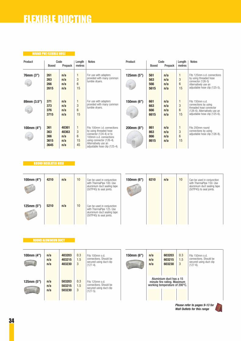
34
Product Code Length NotesBoxed Prepack metres
13615
13615
1361545
261 n/a263 n/a266 n/a2615 n/a
371 n/a373 n/a376 n/a3715 n/a
361 40361363 40363366 n/a3615 n/a3645 n/a
For use with adaptersprovided with many commontumble dryers.
For use with adaptersprovided with many commontumble dryers.
Fits 100mm i.d. connectionsby using threaded hoseconnector (124-4) or to100mm o.d. connectionsusing connector (126-4).Alternatively use anadjustable hose clip (125-4).
76mm (3”)
89mm (3.5”)
100mm (4”)
Product Code Length NotesBoxed Prepack metres
13615
13615
13615
561 n/a563 n/a566 n/a5615 n/a
661 n/a663 n/a666 n/a6615 n/a
861 n/a863 n/a866 n/a8615 n/a
Fits 125mm o.d. connectionsby using threaded hoseconnector (126-5)Alternatively use anadjustable hose clip (125-5).
Fits 150mm o.d.connections by usingthreaded hose connector(126-6). Alternatively use anadjustable hose clip (125-6).
Fits 200mm roundconnections by usingadjustable hose clip (126-8).
125mm (5”)
150mm (6”)
200mm (8”)
10
10
4210 n/a
5210 n/a
Can be used in conjunctionwith ThermaPipe 100. Usealuminium duct sealing tape(50TP45) to seal joints.
Can be used in conjunctionwith ThermaPipe 125. Usealuminium duct sealing tape(50TP45) to seal joints.
100mm (4”)
125mm (5”)
106210 n/a Can be used in conjunctionwith ThermaPipe 150. Usealuminium duct sealing tape(50TP45) to seal joints.
150mm (6”)
0.31.53
0.31.53
n/a 403203n/a 403215n/a 403230
n/a 503203n/a 503215n/a 503230
Fits 100mm o.d.connections. Should besecured using duct clip(127-4).
Fits 125mm o.d.connections. Should besecured using duct clip(127-5).
100mm (4”)
125mm (5”)
0.31.53
n/a 603203n/a 603215n/a 603230
Fits 150mm o.d.connections. Should besecured using duct clip(127-6).
150mm (6”)
ROUND PVC FLEXIBLE HOSE
ROUND INSULATED HOSE
ROUND ALUMINIUM DUCT
Aluminium duct has a 15minute fire rating. Maximum
working temperature of 200°C.
FLEXIBLE DUCTING
Please refer to pages 9-13 forWall Outlets for this range

35
100mm (4”)
125mm (5”)
150mm (6”)
200mm (8”)
Product Code Description Dimensions Notes i.d. = internal dimensionBoxed Prepack mm o.d. = outer dimension
O 100
● 100
● 110
● 90 - 110
● 100 - 110
● 125
● 120 - 140
● 125 - 135
● 150
● 140 - 160
● 150 - 160
● 65 - 215
Used to connect a length of 100mm PVC flexible hose to anyitem with a 100mm i.d. Provides professional finish.
Used to connect a length of 100mm PVC flexible hose to anyitem with a 100mm o.d. Provides professional finish.
Used to connect a length of 100mm PVC flexible hose to110mm soil pipe. Provides professional finish.
Used to connect a length of 100mm PVC flexible hose to anyitem with a 100mm o.d.
Used to to fasten a length of 100mm aluminium duct to100mm o.d. connections.
Used to connect a length of 125mm PVC flexible hose to anyitem with a 125mm o.d. Provides professional finish.
Used to connect a length of 125mm PVC flexible hose to anyitem with a 125mm o.d.
Used to to fasten a length of 125mm aluminium duct to125mm o.d. connections.
Used to connect a length of 150mm PVC flexible hose to anyitem with a 150mm o.d. Provides professional finish.
Used to connect a length of 150mm PVC flexible hose to anyitem with a 150mm o.d.
Mainly used to connect a length of 200mm PVC flexible hoseto any item with a 200mm o.d. However, this can be reducedto 65mm and is therefore suitable for 76 & 89mm flexi hose.
Used to to fasten a length of 150mm aluminium duct to150mm o.d. connections.
124-4 40124 Threaded Hose Connector with Spigot
126-4 40126 Threaded Hose Connector with Socket
126-110 n/a Threaded Hose Connector for 110mm Pipe
125-4 40125* Adjustable Round Hose Clip
127-4 40127* Adjustable Aluminium Duct Clip
126-5 n/a Threaded Hose Connector with Socket
125-5 n/a Adjustable Round Hose Clip
127-5 n/a Adjustable Aluminium Duct Clip
126-6 n/a Threaded Hose Connector with Socket
125-6 n/a Adjustable Round Hose Clip
127-6 n/a Adjustable Aluminium Duct Clip
125-8 n/a Adjustable Hose Clip
* Contains 2 items in retail pack ● = internal dimension O = outer dimension
ROUND HOSE ACCESSORIES
FLEXIBLE DUCTING

36
Product Code Length NotesBoxed Prepack metres
0.53
0.53
3305 40335333 n/a
5305 n/a533 n/a
Slips over System 100channel secured by PVCduct tape (123/123-4).
Slips over Supertube 125channel secured by PVCduct tape (123/123-4).
112 x 56mm
206 x 62mm
Product Code Length NotesBoxed Retail metres
0.53
0.53
5505 n/a5533 n/a
9305 n/a933 n/a
For use with EasiPipe 125.Allows greater flexibilitywhen space is a restriction.Hose forms round to fit125mm connections, eg walloutlets.
Slips over MegaDuct 220channel secured by PVCduct tape (123/123-4).
150 x 60mm
222 x 92mm
Product Code Description Dimensions Notes i.d. = internal dimensionBoxed Prepack mm o.d. = outer dimension
110 x 54
204 x 60
4.6m length50mm wide
33m length50mm wide
Used to connect two pieces of System 100 rectangular hose.Tape joints with duct sealing tape.
Used to connect two pieces of Supertube 125 rectangularhose. Tape joints with duct sealing tape.
To secure rectangular flexible hose to channels or for sealingany duct joint to ensure an airtight connection.
To secure rectangular flexible hose to channels or for sealingany duct joint to ensure an airtight connection.
381 n/a Rectangular Hose Connector 100mm length
581 n/a Rectangular Hose Connector 100mm length
123-4 40123 PVC Duct Sealing Tape
123 n/a PVC Duct Sealing Tape
= outer dimension
RECTANGULAR PVC FLEXIBLE HOSE
RECTANGULAR FLEXIBLE HOSE ACC.
FLEXIBLE DUCTING

37
● Standard boxed kits available to provide solutions to common installations
● Options designed for cooker hoods and tumble dryers
● Air supply and wall outlet sets also available
● Packed in purpose made cartons
● Complete with instructions where necessary
● Choice of wall terminal colours
● Bespoke kits can be designed to meet the exactrequirements of the installation
Domus is able to provide a selection of one-
stop solutions to many popular installations
by choosing from a comprehensive range of
standard boxed kits.
The selection of kits demonstrates the
adaptability of the modular Domus range by
combining products, both rigid and flexible,
with the relevant terminal to achieve the most
effective configuration for the the installation
in question.
Kits are available for short runs that go
straight through the wall or longer runs that
may require installation along the top of wall
units or in the ceiling void. Kits will fit 100mm,
125mm or 150mm diameter connections
providing an option for fans with different
extraction rates. They are available in round
and rectangular form.
There are also kits designed to provide return
air for cooker hoods and combustion air to
open-flued appliances, such as, central
heating boilers and fires.
Domus standard kits are provided, where
necessary, with installation instructions and
are packed in purpose made cardboard
cartons. If the range of standard kits does not
provide a suitable answer, bespoke kits can
be designed to meet the exact specification of
the installation.
Outlet Colours
All kits come with a choice of colour for the
external outlet of white, brown, terracotta or
cotswold (beige). All internal outlets and
ducting are supplied in white only. The colour
of external outlet required must be stated
when ordering.
Fixing Kits
Some kits contain a fixing kit. This consists
of: 8 wall plugs and screws for wall outlet
fixing and 4 adhesive (single sided) foam pads
to aid loose fits.
BOXED KITS
AIR SUPPLY SETS
Typical usage
An extractor fan removes air causing the
pressure in the room to drop if not replaced.
A lack of supply causes the windows to mist
up and also increases the noise from the
cooker hood motor, as it has to work harder.
In order to prevent this the airflow must be
balanced by ensuring an adequate amount of
return air back into the room.
A Domus air supply kit should be installed into
an outside wall of the room, preferably
opposite to the extraction unit.

38
Product Kit Parts Description Qty Duct SpecificationsCode size mm
58.5cm2
19.0 kWTo fit through walls250-450mm
92cm2
26.0 kWTo fit through walls250-450mm
132cm2
38.5 kWTo fit through walls250-450mm
49.5cm2
17.5 kWTo fit through wallsup to 400mm
64.5cm2
22.0 kWTo fit through wallsup to 400mm
151.8cm2
52.5 kWTo fit through wallsup to 400mm
EasiPipe 100 Round Telescopic Return air Box116 F4904 Louvred Grille with Flyscreen - Round Spigot 1 100
4904 Louvred Grille - Round Spigot 1130-4 Telescopic Pipe, 250-450mm 1
EasiPipe 125 Round Telescopic Return Air Box516 F5904 Louvred Grille with Flyscreen - Round Spigot 1 125
5904 Louvred Grille - Round Spigot 1E130-5 Telescopic Pipe with Enlarged End, 250-450mm 1
EasiPipe 150 Round Telescopic Return Air Box616 F6904 Louvred Grille with Flyscreen - Round Spigot 1 150
6904 Louvred Grille - Round Spigot 1E130-6 Telescopic Pipe with Enlarged End, 250-450mm 1
System 100 Telescopic Return Air Box117 F4905 Louvred Grille with Flyscreen - Rectangular Socket 1 110 x 54
4905 Louvred Grille - Rectangular Socket 1D1-0400 Flat Channel, 400mm 1
Supertube 125 Rectangular Return AirBox with Internal Damper
511 501 Horizontal Airbrick (Flap Removed) 1 204 x 60501 Horizontal Airbrick with Damper (Centre Pivot Flap) 1D3-0400 Flat Channel, 400mm 1115-5 Rectangular Wall Plate 2
Megaduct 220 Rectangular Return Air Box917 905 Double Airbrick 2 220 x 90
977 Double Airbrick Adapter 2D4-0400 Flat Channel, 400mm 1
Great care must be taken to ensure that the
amount of air back flow provided is at least
equal to the combined consumption and
extraction rate of all appliances.
It is recommended that an air supply set
should be installed in every room where air is
being mechanically removed.
WARNING!
Open flued appliances, such as an Aga cooker
or a gas fired hot water appliance maintains
combustion by burning air from the kitchen.
An extraction unit removing air from the
kitchen without return air can starve the
appliance of enough oxygen and in some
cases can cause a reversal of flue gases, which
can cause carbon monoxide poisoning.
If an open flued appliance coexists with an
extraction unit, then the extraction unit and
its air supply vents must conform to the
Building Regulations and a BS5440 product
spillage test should be undertaken with the
extracting appliance in operation. Gas hobs,
gas ovens and balanced flue (room sealed)
appliances are exempt from this test.
Balanced flue boilers have no permanently
open air leakage paths and are therefore not
affected by air extraction.
A selection of air supply sets is available to
meet most domestic requirements. Reference
should be made to BS 5440-2 to determine
the most suitable kit for the appliance
concerned.
250-450mm
250-450mm
250-450mm
400mm
400mm
AIR SUPPLY SETS CONT.
BOXED KITS
400mm

39
Product Kit Parts Description Qty Duct ApplicationCode size mm
100mm 1m Round Hose Kit with Cowled Wall Outlet202 4902 Cowled Wall Outlet with Damper - Round Spigot 1 100
361 Round PVC Flexible Hose, 1m 1114-4 Round Wall Plate 1126-4 Threaded Hose Connector with Socket 2
Fixing Kit 1
Also available prepacked ref 40202
125mm 1m Round Hose Kit with Cowled Wall Outlet202-5 5902 Cowled Wall Outlet with Damper - Round Spigot 1 125
561 Round PVC Flexible Hose, 1m 1114-5 Round Wall Plate 1126-5 Threaded Hose Connector with Socket 2
Fixing Kit 1
150mm 1m Round Hose Kit with Cowled Wall Outlet202-6 6902 Cowled Wall Outlet with Damper - Round Spigot 1 150
661 Round PVC Flexible Hose, 1m 1114-6 Round Wall Plate 1126-6 Threaded Hose Connector with Socket 2
Fixing Kit 1
Typical usage
Flexible hose kits are ideal for short duct runs
(under 3m) and, therefore, suitable for the
ducting of tumble dryers or cooker hoods
situated on an external wall. It is important
that the flexible hose is kept as taut as
possible and, when possible, in a straight line
to ensure maximum airflow performance.
Extra care must be taken when installing the
hose through the brickwork as the hose could
tear, resulting in reduced performance.
Flexible hose kits are provided with adhesive
pads, to ensure that the duct connection to
the appliance exhaust spigot is secure - as
diameters can vary slightly between
manufacturers.
Kits are available with a choice of wall outlet
styles - please refer to the wall outlet section
to assist in deciding your choice of outlet.
IMPORTANT
Options are available in 100, 125 and
150mm and the appropriate kit should be
selected according to the spigot size of
the appliance and the extraction power of
the unit (in the case of cooker hoods/fans).
Please refer to the manufacturer for
guidelines, or use our recommendation in the
tables below.
Please note that the manufacturer’s warranty
may be invalidated if the correct size ducting
is not used.
Further options for the ducting of tumble
dryers are detailed later.
FLEXIBLE HOSE DUCTING KITS
1m
1m
1m
up to 400 m3/hr
400 m3/hr plus
up to 250 m3/hr
BOXED KITS

40
Product Kit Parts Description Qty Duct ApplicationCode size mm
100mm 1m Round Hose Kit with Gravity Flap Outlet205 4900 Wall Outlet with Gravity Flaps - Round Spigot 1 100
361 Round PVC Flexible Hose, 1m 1114-4 Round Wall Plate 1126-4 Threaded Hose Connector with Socket 2
Fixing Kit 1
Also available prepacked ref 40205
125mm 1m Round Hose Kit with Gravity Flap Outlet216 5900 Wall Outlet with Gravity Flaps - Round Spigot 1 125
561 Round Flexible Hose, 1m 1114-5 Round Wall Plate 1126-5 Threaded Hose Connector with Socket 2
Fixing Kit 1
150mm 1m Round Hose Kit with Gravity Flap Outlet225 6900 Wall Outlet with Gravity Flaps - Round Spigot 1 150
661 Round Flexible PVC Hose, 1m 1126-6 Threaded Hose Connector with Socket 2114-6 Round Wall Plate 1
Fixing Kit 1
125mm 1m Hose Kit with Louvred Grille &Internal Damper
215 500 Louvred Grille with Internal Damper - Round Spigot 1 125561 Round PVC Flexible Hose, 1m 1114-5 Round Wall Plate 1126-5 Threaded Hose Connector with Socket 2
Fixing Kit 1
1m
1m
1m
1m
FLEXIBLE HOSE DUCTING KITS CONT.
up to 250 m3/hr
up to 400 m3/hr
up to 400 m3/hr
400 m3/hr plus
BOXED KITS

41
Product Kit Parts Description Qty DuctCode size mm
EasiPipe 100 100mm Round Telescopic Outlet Set108 4902 Cowled Wall Outlet with Damper - Round Spigot 1 100
130-4 Telescopic Pipe, 250-450mm 1114-4 Round Wall Plate 1
Also available prepacked ref 40108
EasiPipe 125 Round Telescopic Outlet Set withInternal Damper
508 500 Louvred Grille with Internal Damper - Round Spigot 1 125P3-0175 Round Inner Pipe, 175mm 1P4-0275 Round Pipe, 275mm 1114-5 Round Wall Plate 1
EasiPipe 150 Round Telescopic Outlet Set608 6904 Louvred Grille - Round Spigot 1 150
130-6 Telescopic Pipe, 250-450mm 1114-6 Round Wall Plate 1
EasiPipe 100 Round Telescopic Outlet withInternal Damper
112 4904 Louvred Grille - Round Spigot 1 100130-4 Telescopic Pipe, 250-450mm 1495 Straight Pipe Connector with Damper and Wall Plate 1
Fixing Kit 1
Typical usage
Designed for installation through the walls of
most standard housing.
Wall outlet sets provide the connection
terminal inside the house for (in most cases)
additional ducting, but can also be connected
direct to an appliance (a connector/adapter
may be needed).
Rigid ducting offers better airflow
performance than a flexible duct and its use is
recommended if possible.
Options are available in the System 100
range and in 100, 125, 150mm and EasiPipe
ranges. All kits have a back draft prevention
device to stop draughts coming back into the
room when the fan is not in use.
WALL OUTLET SETS
BOXED KITS

42
Product Kit Parts Description Qty DuctCode size mm
EasiPipe 125 Round Telescopic Outlet withInternal Damper
512 5904 Louvred Grille - Round Spigot 1 125E130-5 Telescopic Pipe with Enlarged End, 250-450mm 1595 Straight Pipe Connector with Damper and Wall Plate 1
Fixing Kit 1
EasiPipe 150 Round Telescopic Outlet withInternal Damper
612 6904 Louvred Grille - Round Spigot 1 150E130-6 Telescopic Pipe with Enlarged End, 250-450mm 1695 Straight Pipe Connector with Damper and Wall Plate 1
Fixing Kit 1
System 100 Rectangular Outlet Set 2455 F4905 Louvred Grille with Flyscreen - Rectangular Socket 1 110 x 54
107 Damper Valve and Wall Plate 1D1-0400 Flat Channel, 400mm 1
WALL OUTLET SETS CONT.
BOXED KITS
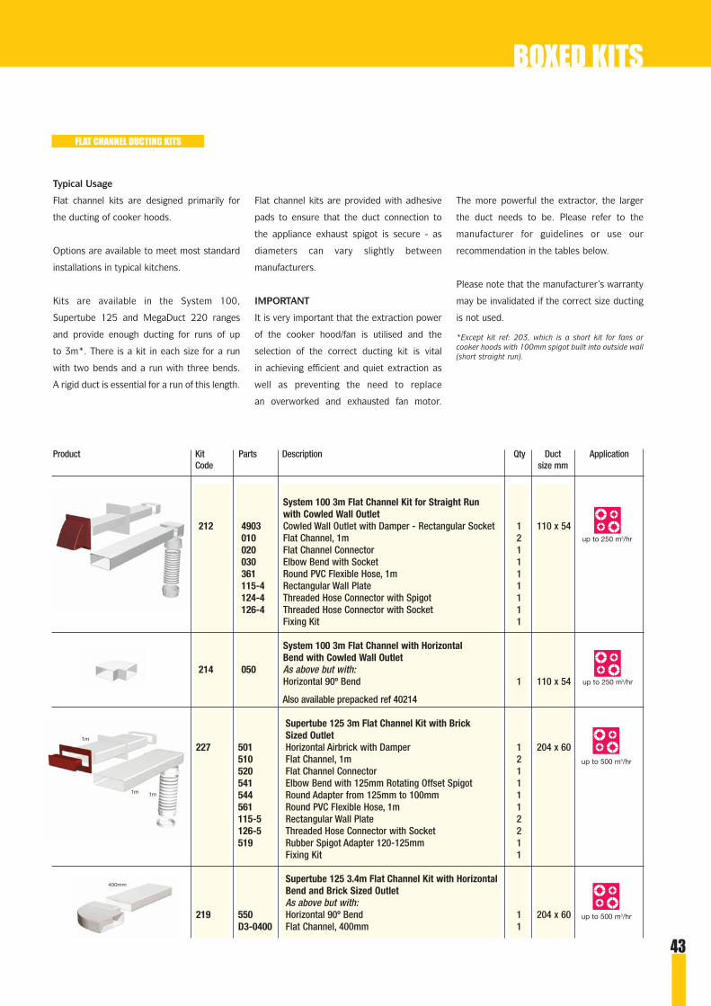
43
Product Kit Parts Description Qty Duct ApplicationCode size mm
System 100 3m Flat Channel Kit for Straight Runwith Cowled Wall Outlet
212 4903 Cowled Wall Outlet with Damper - Rectangular Socket 1 110 x 54010 Flat Channel, 1m 2020 Flat Channel Connector 1030 Elbow Bend with Socket 1361 Round PVC Flexible Hose, 1m 1115-4 Rectangular Wall Plate 1124-4 Threaded Hose Connector with Spigot 1126-4 Threaded Hose Connector with Socket 1
Fixing Kit 1
System 100 3m Flat Channel with HorizontalBend with Cowled Wall Outlet
214 050 As above but with:Horizontal 90º Bend 1 110 x 54
Also available prepacked ref 40214
Supertube 125 3m Flat Channel Kit with BrickSized Outlet
227 501 Horizontal Airbrick with Damper 1 204 x 60510 Flat Channel, 1m 2520 Flat Channel Connector 1541 Elbow Bend with 125mm Rotating Offset Spigot 1544 Round Adapter from 125mm to 100mm 1561 Round PVC Flexible Hose, 1m 1115-5 Rectangular Wall Plate 2126-5 Threaded Hose Connector with Socket 2519 Rubber Spigot Adapter 120-125mm 1
Fixing Kit 1
Supertube 125 3.4m Flat Channel Kit with HorizontalBend and Brick Sized OutletAs above but with:
219 550 Horizontal 90º Bend 1 204 x 60D3-0400 Flat Channel, 400mm 1
Typical Usage
Flat channel kits are designed primarily for
the ducting of cooker hoods.
Options are available to meet most standard
installations in typical kitchens.
Kits are available in the System 100,
Supertube 125 and MegaDuct 220 ranges
and provide enough ducting for runs of up
to 3m*. There is a kit in each size for a run
with two bends and a run with three bends.
A rigid duct is essential for a run of this length.
Flat channel kits are provided with adhesive
pads to ensure that the duct connection to
the appliance exhaust spigot is secure - as
diameters can vary slightly between
manufacturers.
IMPORTANT
It is very important that the extraction power
of the cooker hood/fan is utilised and the
selection of the correct ducting kit is vital
in achieving efficient and quiet extraction as
well as preventing the need to replace
an overworked and exhausted fan motor.
The more powerful the extractor, the larger
the duct needs to be. Please refer to the
manufacturer for guidelines or use our
recommendation in the tables below.
Please note that the manufacturer’s warranty
may be invalidated if the correct size ducting
is not used.
*Except kit ref: 203, which is a short kit for fans orcooker hoods with 100mm spigot built into outside wall(short straight run).
FLAT CHANNEL DUCTING KITS
up to 250 m3/hr
up to 250 m3/hr
up to 500 m3/hr
up to 500 m3/hr
1m1m
1m
400mm
BOXED KITS

44
Product Kit Parts Description Qty Duct ApplicationCode size mm
MegaDuct 220 3m Flat Channel Kit with RoundCowled Outlet
2650 6902 Round Cowled Outlet - Round Spigot 1 220 x 90135-6 Round Pipe, 350mm 1970 Round to Rectangular Adapter 1910 Flat Channel, 1m 2920 Flat Channel Connector 1950 Horizontal 90° Bend 1961 Elbow Bend with 150mm Rotating Offset Spigot 1126-6 Threaded Hose Connector with Socket 2661 Round PVC Flexible Hose, 1m 1
Fixing Kit 1
MegaDuct 220 3m Flat Channel Kit with BrickSized Outlet
2653 905 Double Airbrick 1 220 x 90977 Double Airbrick Adapter 1910 Flat Channel, 1m 2920 Flat Channel Connector 1950 Horizontal 90° Bend 1961 Elbow Bend with 150mm Rotating Offset Spigot 1126-6 Threaded Hose Connector with Socket 2661 Round PVC Flexible Hose, 1m 1
Fixing Kit 1
Product Kit Parts Description Qty Duct ApplicationCode size mm
System 100 Short Extractor Fan Kit with BrickSized Outlet
203 501 Horizontal Airbrick with Damper 1 110 x 54077 Airbrick Adapter 1D1-0150 Flat Channel, 150mm 1070 Round to Rectangular Adapter 1
An additional selection of kits for use with thestylish range of Domus extractor fans isdetailed in the Fan section of this catalogue.
EXTRACTOR FAN KIT
150mm
FLAT CHANNEL DUCTING KITS CONT.
up to & above1000 m3/hr
up to & above1000 m3/hr
BOXED KITS
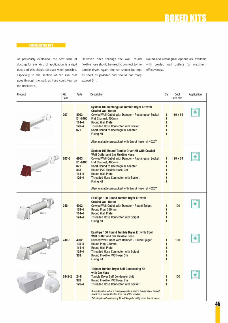
45
Product Kit Parts Description Qty Duct ApplicationCode size mm
System 100 Rectangular Tumble Dryer Kit withCowled Wall Outlet
207 4903 Cowled Wall Outlet with Damper - Rectangular Socket 1 110 x 54D1-0400 Flat Channel, 400mm 1114-4 Round Wall Plate 1126-4 Threaded Hose Connector with Socket 1071 Short Round to Rectangular Adapter 1
Fixing Kit 1
Also available prepacked with 2m of hose ref 40207
System 100 Round Tumble Dryer Kit with CowledWall Outlet and 3m Flexible Hose
207-3 4903 Cowled Wall Outlet with Damper - Rectangular Socket 1 110 x 54D1-0400 Flat Channel, 400mm 1071 Short Round to Rectangular Adapter 1363 Round PVC Flexible Hose, 3m 1114-4 Round Wall Plate 1126-4 Threaded Hose Connector with Socket 1
Fixing Kit 1
Also available prepacked with 2m of hose ref 40207
EasiPipe 100 Round Tumble Dryer Kit withCowled Wall Outlet
240 4902 Cowled Wall Outlet with Damper - Round Spigot 1 100135-4 Round Pipe, 350mm 1114-4 Round Wall Plate 1124-4 Threaded Hose Connector with Spigot 1
Fixing Kit 1
EasiPipe 100 Round Tumble Dryer Kit with CowlWall Outlet and 3m Flexible Hose
240-3 4902 Cowled Wall Outlet with Damper - Round Spigot 1 100135-4 Round Pipe, 350mm 1114-4 Round Wall Plate 1124-4 Threaded Hose Connector with Spigot 1363 Round Flexible PVC Hose, 3m 1
Fixing Kit 1
100mm Tumble Dryer Self Condensing Kit with 2m Hose
2442-2 2441 Tumble Dryer Self Condenser Unit 1 100362 Round Flexible PVC Hose, 2m 1126-4 Threaded Hose Connector with Socket 1
As previously explained, the best form of
ducting for any kind of application is a rigid
duct and this should be used when possible,
especially in the section of the run that
goes through the wall, as hose could tear on
the brickwork.
However, once through the wall, round
flexible hose should be used to connect to the
tumble dryer. Again, the run should be kept
as short as possible and should not really
exceed 3m.
Round and rectangular options are available
with cowled wall outlets for maximum
effectiveness.
TUMBLE DRYER KITS
350mm
350mm
400mm
400mm
BOXED KITS
A simple option when it is inappropriate to duct a tumble dryer througha wall or to dangle flexible hose out of the window.
This simple self condensing kit will keep the utility room free of steam.

46
Product Kit Parts Description Qty Duct ApplicationCode size mm
EasiPipe 150 3m Round Pipe Kit for Straight Runwith Cowled Wall Outlet
2605 6902 Cowled Wall with Damper - Round Spigot 1 1501100-6 Round Pipe, 1m 2693 Straight Pipe Connector 1690 90º Bend 1114-6 Round Wall Plate 1126-6 Threaded Hose Connector with Socket 2661 Round PVC Flexible Hose 1m 1
Fixing Kit 1
EasiPipe 150 3m Round Pipe Kit with HorizontalBend with Cowled Wall Outlet
2607 6902 Cowled Wall with Damper - Round Spigot 1 1501100-6 Round Pipe Connector, 1m 2693 Straight Pipe Connector 1690 90º Bend 2114-6 Round Wall Plate 1126-6 Threaded Hose Connector with Socket 2661 Round PVC Flexible Hose, 1m 1
Fixing Kit 1
Typical usage
The Domus range of 150mm round pipe kits
is designed primarily for the ducting of very
high powered cooked hoods. A round, rigid
pipe is the most efficient and effective duct to
achieve maximum airflow performance.
Options are available to meet most standard
installations in typical kitchens.
Kits provide enough ducting for runs of up to
3m. There is a kit for a run with two bends
and a run with three bends.
Round pipe kits are provided with adhesive
pads to ensure that the duct connection to
the appliance exhaust spigot is secure, as
diameters can vary slightly between
manufacturers.
IMPORTANT
It is very important that the extraction power
of the cooker hood/fan is utilised and the
selection of the correct ducting kit is vital in
achieving efficient and quiet extraction, as
well as preventing the need to replace an
overworked and exhausted fan motor. The
more powerful the extractor, the larger the
duct needs to be. Please refer to the
manufacturer for guidelines or use our
recommendation in the tables below.
Please note that the manufacturer’s warranty
may be invalidated if the correct size ducting
is not used.
ROUND PIPE DUCTING KITS
1m
1m
1m
1m
1m
1m
E & EO We reserve the right to alter kit specifications without prior notice.
500 m3/hr plus
500 m3/hr plus
BOXED KITS

47
The ventilation ducting intumescent connector
Prevent the spread of fire through ventilation ducting

48
● Meets the requirements of Approved Document B of the UK Building Regulations
● Meets the requirements of NHBC Standard (April 2004) 8.1-S2 (f)
● Tested by BRE to BS 476 Part 20: 1987 and prEN 1366-3
● 2 hour fire rating
● Available for all five sizes of Domus flat channel ducting systems
The Domus FireBrake is a unique, scientifically
advanced intumescent product to prevent the
spread of fire through plastic ventilation ducting
systems. It has been designed specifically for its
intended purpose.
Fire prevention is a serious concern. Building
Regulations state that when a compartment wall
is penetrated an approved fire-stopping device
should be installed. The purpose is to contain
fire spread that could be harmful to life, and to
maintain the integrity of the building for as long
as possible.
FireBrake reacts to the heat from the fire and
expands inwards stopping the spread of the fire
by quickly providing a 100% closed fire stop
seal.
FireBrake has been designed with safety of the
householder as its primary concern. This gives
the installer unparalleled peace of mind that the
installation is fit for purpose and will pass
inspection by Building Control.
FireBrake allows simple but effective installation
to deal with most common problems faced on
site which often make alternative options like
fire collars and wraps unsuitable.
Due to its construction, design features, and
user friendly nature you can specify and install
FireBrake with confidence.
FireBrake is available for all five sizes of Domus
flat channel ducting systems.
Quick and easy installation
Domus FireBrake is very simple to install.
Its user friendly nature avoids
improvisation during fitting particularly
in areas that are difficult to access.
This is a significant advantage over wraps
and collars.
FireBrake ensures professional
installation. It is the correct fire stop for all
Domus rectangular ventilation ducting.
In most fire-stopping applications two
collars or wraps are required, one on
either side. Thus FireBrake can provide
substantial cost savings, especially
in installation time. No maintenance
is required.
For masonry or stud walls and
concrete floors
Domus FireBrake is designed for multi-
purpose installation. For stud walls the
steel casing (fitted as standard) ensures
that the product closes inwards. The
125mm length of FireBrake is sufficient to
prevent it falling through a stud wall once
the duct has melted away. This is not the
case with most collars. Wraps are not
suitable for use within stud walls.
Robust Construction
Domus FireBrake is strong enough to cope
with the rigours of transportation and the
hazardous environment on building sites.
Its sturdy nature inspires confidence that it
will be fit for purpose.
No additional fixings necessary
The Domus FireBrake does not require
additional fixings, such as screws and
metal anchors. This saves considerable
time and money on site.
Forms an integral part of the
ducting system
Domus FireBrake acts as a connector.
It can be incorporated as part of the
ducting system design providing a
seamless configuration.
Designed to put safety first
Domus FireBrake helps prevent careless
installation. This is a common problem
with wraps and collars as they are difficult
to work with. Careless installation can
result in failure under fire conditions.
FIREBRAKE
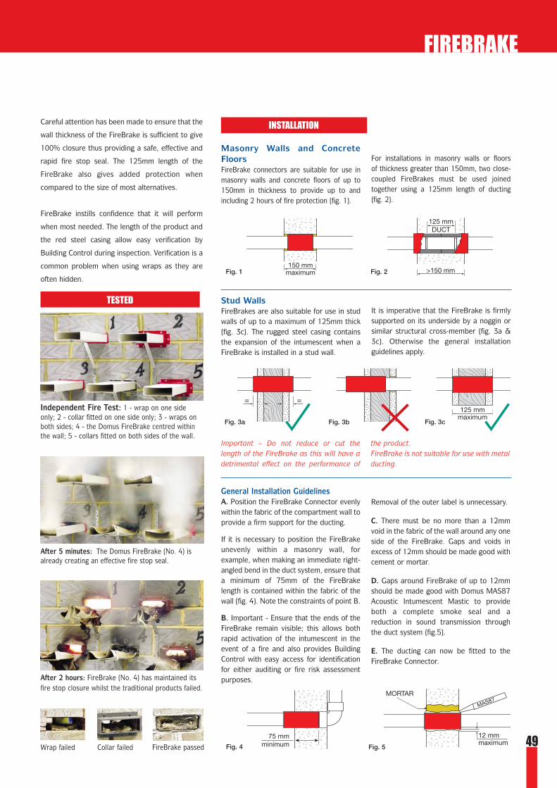
3
49
Careful attention has been made to ensure that the
wall thickness of the FireBrake is sufficient to give
100% closure thus providing a safe, effective and
rapid fire stop seal. The 125mm length of the
FireBrake also gives added protection when
compared to the size of most alternatives.
FireBrake instills confidence that it will perform
when most needed. The length of the product and
the red steel casing allow easy verification by
Building Control during inspection. Verification is a
common problem when using wraps as they are
often hidden.
Independent Fire Test: 1 - wrap on one sideonly; 2 - collar fitted on one side only; 3 - wraps onboth sides; 4 - the Domus FireBrake centred withinthe wall; 5 - collars fitted on both sides of the wall.
After 5 minutes: The Domus FireBrake (No. 4) isalready creating an effective fire stop seal.
After 2 hours: FireBrake (No. 4) has maintained itsfire stop closure whilst the traditional products failed.
Wrap failed Collar failed FireBrake passed
FIREBRAKE
TESTED
Masonry Walls and ConcreteFloorsFireBrake connectors are suitable for use inmasonry walls and concrete floors of up to150mm in thickness to provide up to andincluding 2 hours of fire protection (fig. 1).
For installations in masonry walls or floors of thickness greater than 150mm, two close-coupled FireBrakes must be used joinedtogether using a 125mm length of ducting (fig. 2).
Important – Do not reduce or cut thelength of the FireBrake as this will have adetrimental effect on the performance of
the product.FireBrake is not suitable for use with metalducting.
Stud Walls FireBrakes are also suitable for use in studwalls of up to a maximum of 125mm thick (fig. 3c). The rugged steel casing containsthe expansion of the intumescent when aFireBrake is installed in a stud wall.
It is imperative that the FireBrake is firmlysupported on its underside by a noggin orsimilar structural cross-member (fig. 3a &3c). Otherwise the general installationguidelines apply.
INSTALLATION
General Installation GuidelinesA. Position the FireBrake Connector evenlywithin the fabric of the compartment wall toprovide a firm support for the ducting.
If it is necessary to position the FireBrakeunevenly within a masonry wall, forexample, when making an immediate right-angled bend in the duct system, ensure thata minimum of 75mm of the FireBrakelength is contained within the fabric of thewall (fig. 4). Note the constraints of point B.
B. Important - Ensure that the ends of theFireBrake remain visible; this allows bothrapid activation of the intumescent in theevent of a fire and also provides BuildingControl with easy access for identificationfor either auditing or fire risk assessmentpurposes.
Removal of the outer label is unnecessary.
C. There must be no more than a 12mmvoid in the fabric of the wall around any oneside of the FireBrake. Gaps and voids inexcess of 12mm should be made good withcement or mortar.
D. Gaps around FireBrake of up to 12mmshould be made good with Domus MAS87Acoustic Intumescent Mastic to provideboth a complete smoke seal and areduction in sound transmission throughthe duct system (fig.5).
E. The ducting can now be fitted to theFireBrake Connector.
150 mmmaximum >150 mm
125 mmDUCT
Fig. 1 Fig. 2
75 mmminimum
12 mmmaximum
MORTAR
Fig. 4 Fig. 5
= =125 mm
maximumFig. 3bFig. 3a Fig. 3c

50
FIREBRAKE
Fit for purpose. Acts as a connector. Profile specifically designed forducting.
The steel casing ensures inwardsclosure.
Intumescent mastic completesthe perfect installation.
Code Description Dimensions mmBoxed Prepack Length Overall/Fitting
087 n/a System 100 FireBrake 125 124 x 68Duct Connector 110 x 54
587 n/a Supertube 125 FireBrake 125 218 x 74Duct Connector 204 x 60
987 n/a MegaDuct 220 FireBrake 125 241 x 111Duct Connector 220 x 90
2087 n/a PolyVent 225 FireBrake 125 248 x 43Duct Connector 234 x 29
3087 n/a PolyVent 300 FireBrake 125 322 x 43Duct Connector 308 x 29
Code Description VolumeBoxed Prepack
MAS87 n/a Acoustic Intumescent Mastic 310 ml Apply using a standardsealant applicator gun.
Product
Certification and mechanical health and safety data sheets are available on request from our technical department.
If you are in doubt on any aspect of this product, please phone our technical department on 01799 540602 or email [email protected]
DUCTING FOR FIREBRAKE
For System 100 Ducting see pages 15-16For Supertube 125 Ducting see pages 18-19For MegaDuct 220 Ducting see page 21For PolyVent Ducting see pages 23-24
= internal dimensions = outer dimensions
Connects over System 100 flatchannel lengths providing a secureseal.
Connects over Supertube 125 flatchannel lengths providing a secureseal.
Connects over MegaDuct 220 flatchannel lengths providing a secureseal.
Connects over PolyVent 225 flatchannel lengths providing a secureseal.
Connects over PolyVent 300 flatchannel lengths providing a secureseal.
Notes
Notes
Four hour fire rating.Meets BS476: Part 20.

toilet
shower
bathroom
kitchen
utility room
whole house
S E L V R A T E D
1 to 25 mins
ROOM LOCATIONS MODEL OPTIONSstandardSwitch fan on/off manually by remote switch e.g. light switch/dedicated switch.
pull switchSwitch fan on/off manually using integral pullswitch.
timerFan switches on using a remote switch (light)and includes an adjustable overrun timer (1 to 25 mins) so that the fan continues toremove excess moisture and odours afterswitching off the fan.
movement detectorSensitive to movement coupled with heatpreventing accidental tripping. Switches onwhen body movement is detected. Also includestimer function.
humidistatSwitches on/off automatically once a presetlevel of humidity is reached. Integralcondensation control is adjustable between 60and 80% RH @ 21 °C, which enables the fan tocontinuously monitor humidity. Also includestimer function.
humidistat/pull switchSpecification as humidistat version but with theadditional of a pull switch for manual override.
auto shutterShutters open during operation and close whennot in use to prevent back drafts. Available withtimer or pull switch and as a standard model.Operated by a silent thermoactuator.
SELV12V fan or light unit.
ICONS
To assist in fan
selection, icons are
used throughout this
catalogue. These are
used to indicate the
room that the fan can
be used in and the
model type.
The product codes throughout this catalogue are
shown as either a Boxed or Prepacked option.
This refers to the type of packaging that the
product will be supplied in.
PRODUCT CODES/PACKAGING TYPE
Boxed Prepacked
51
* Except T1C, T1EC, P1C and ELF Models
THE DOMUS PLEDGE OF SAFETY AND QUALITY
Domus fans are tested to the strictest levels of qualityand safety providing one of the safest fans on the market.
● BSI Kitemarked to BS EN 60335 for electrical safety*
● Tested by BSRIA for airflow performance to ISO 5801
● Sound tested by SRL to ISO 3741:1988 (reports available)
● Fans exceed the requirements of the Building Regulations
● Fans are made from tough fire retardant UV stabilised materials
● Fans are easily cleaned, maintained and installed
● Splash-proof rated
● Domus is a member of a BS EN ISO 9002 registered group
● Easy to follow and comprehensive instructions
● Robust packaging protects the fans

52
DOMUS 100MM AXIAL FANS
● Exceeds Building Regulations for bathrooms and toilets
● Window or wall fixing options
● BSI Kitemarked to BS EN 60335 for electrical safety
● IPx4 Splash-proof rating
● Tough white high gloss ABS (fire retardant and UV stabilised)
● Multiple model options
● Stainless steel ball bearing versions
● Quick and easy installation
● Three year guarantee
The DOMUS 100mm axial fan is a stylish unit
made from safe, durable, easily cleaned high
gloss ABS. Suitable for wall or window
installation.
Model options include: Standard, Pull-cord
Switch, Timer, Humidistat (with or without
Pull-cord Switch), Movement Detector, Auto
Shutter and SELV 12V enabling the range to
meet most installation requirements. Some
models are also available with a stainless steel
ball bearing motor providing greater
efficiency, lower noise and longer life.
The SELV 12V fan used in conjunction with a
Domus transformer (see page 74) is suitable
for safety critical domestic environments
and can, therefore, be safely installed within
zone 1 near a bath or shower, as stated
in amendment 3 of BS7671:1992. The
transformer must be mounted away from the
source of water spray and out of the safety
critical area.
The 100mm range exceeds the Building
Regulation requirement of 15 l/s for
bathrooms.
I n te
ll
ig
en
tm o v e m e n t
d e t e c t i o n
100º82º
Plan View
5m max
.
5m max
.
Side View
Movement from Y, detection distance is shortened.
Y
X
MOVEMENT DETECTION RANGE
Passive Infra-red MovementDetector fans incorporate theworld’s smallest passive infra red sensor fitted to a domestic fan

53
DOMUS 100MM AXIAL FANS
Standard FansS1 S1R Wall FanSB1 n/a Wall Fan with Ball Bearing MotorS1W S1WR Window FanS1K S1KR Wall Fan & Wall Fixing Kit
Pull Switch FansP1 P1R Wall FanPB1 n/a Wall Fan with Ball Bearing MotorP1W P1WR Window FanP1K P1KR Wall Fan & Wall Fixing Kit
Timer FansT1 T1R Wall FanTB1 n/a Wall Fan with Ball Bearing MotorT1W T1WR Window FanT1K T1KR Wall Fan & Wall Fixing Kit
Movement Detector FansM1 n/a Wall FanMB1 n/a Wall Fan with Ball Bearing Motor
Humidistat FansH1 H1R Wall FanH1W H1WR Window FanH1K H1KR Wall Fan & Wall Fixing Kit
Humidistat/Pull Switch FansHP1 HP1R Wall FanHP1W HP1WR Window FanHP1K HP1KR Wall Fan & Wall Fixing Kit
Auto Shutter FansAS1 n/a Standard Wall FanAP1 n/a Pull Switch Wall FanAT1 n/a Timer Wall Fan
Product Code Description Extract performance Power dB(A) Weight ModelBoxed Prepack l/s m3/hr cfm W @ 3m kg
26 94 55 15 38.8 0.626 94 55 15 38.8 0.618 65 38 15 38.8 0.624 86 50 15 38.8 0.6
26 94 55 15 38.8 0.626 94 55 15 38.8 0.618 65 38 15 38.8 0.624 86 50 15 38.8 0.6
26 94 55 15 38.8 0.626 94 55 15 38.8 0.618 65 38 15 38.8 0.624 86 50 15 38.8 0.6
26 94 55 15 38.8 0.626 94 55 15 38.8 0.6
26 94 55 15 38.8 0.618 65 38 15 38.8 0.624 86 50 15 38.8 0.6
26 94 55 15 38.8 0.618 65 38 15 38.8 0.624 86 50 15 38.8 0.6
26 94 55 21 38.8 0.726 94 55 21 38.8 0.726 94 55 21 38.8 0.7
1 to 25 mins
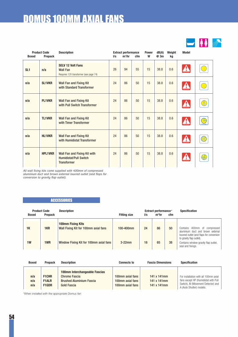
54
Product Code Description Extract performance Power dB(A) Weight ModelBoxed Prepack l/s m3/hr cfm W @ 3m kg
26 94 55 15 38.8 0.6
24 86 50 15 38.8 0.6
24 86 50 15 38.8 0.6
24 86 50 15 38.8 0.6
24 86 50 15 38.8 0.6
24 86 50 15 38.8 0.6
SELV 12 Volt FansSL1 n/a Wall Fan
Requires 12V transformer (see page 74)
n/a SL1VKR Wall Fan and Fixing Kit with Standard Transformer
n/a PL1VKR Wall Fan and Fixing Kit with Pull Switch Transformer
n/a TL1VKR Wall Fan and Fixing Kit with Timer Transformer
n/a HL1VKR Wall Fan and Fixing Kit with Humidistat Transformer
n/a HPL1VKR Wall Fan and Fixing Kit with Humidistat/Pull Switch Transformer
All wall fixing kits come supplied with 400mm of compressedaluminium duct and brown external louvred outlet (and flaps forconversion to gravity flap outlet).
DOMUS 100MM AXIAL FANS
S E L V R A T E D
S E L V R A T E D
S E L V R A T E D
S E L V R A T E D
S E L V R A T E D
S E L V R A T E D
1 to 25 mins
ACCESSORIES
Product Code Description Extract performance* SpecificationBoxed Prepack Fitting size l/s m3/hr cfm
100mm Fixing Kits1K 1KR Wall Fixing Kit for 100mm axial fans 100-400mm 24 86 50
1W 1WR Window Fixing Kit for 100mm axial fans 3-22mm 18 65 38
Contains 400mm of compressedaluminium duct and brown externallouvred outlet (and flaps for conversionto gravity flap outlet).
Contains window gravity flap outlet,seal and fixings.
Boxed Prepack Description Connects to Fascia Dimensions Specification
100mm Interchangeable Fasciasn/a F1CHR Chrome Fascia 100mm axial fans 141 x 141mmn/a F1ALR Brushed Aluminium Fascia 100mm axial fans 141 x 141mmn/a F1GDR Gold Fascia 100mm axial fans 141 x 141mm
For installation with all 100mm axialfans except HP (Humidistat with PullSwitch), M (Movement Detector) andA (Auto Shutter) models.
*When installed with the appropriate Domus fan

55
PERFORMANCE GRAPH
AXIAL FANS
Tested to ISO 5801:1997 (TYPE A). BSRIA Report Number14404/1 03/99.
DIMENSIONS
All measurements in mm. Drawings not to scale.
ELECTRICAL SPECIFICATIONS
220-240 V ~ 50Hz (SELV versions 12 V ~ 50Hz)
Insulation class II / Double insulated
Splash-proof (equivalent IPx4)
Motors fitted with standard thermal fuses
(SELV versions motor fitted with auto-reset
thermal cutouts)
Wiring must comply with latest IEE Wiring
Regulations (BS7671)
DOMUS 100MM AXIAL FANS
Axial fans are designed for air movement
over short distances as the air enters and
leaves the impellers parallel with the fan
axis. As a result, typical installations
would be through a wall or a window.
Domus axial fans should only be used for
short duct runs up to a maximum of 1.5m.
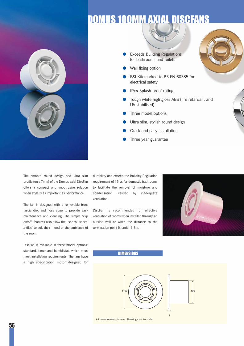
56
DOMUS 100MM AXIAL DISCFANS
● Exceeds Building Regulations for bathrooms and toilets
● Wall fixing option
● BSI Kitemarked to BS EN 60335 for electrical safety
● IPx4 Splash-proof rating
● Tough white high gloss ABS (fire retardant and UV stabilised)
● Three model options
● Ultra slim, stylish round design
● Quick and easy installation
● Three year guarantee
DIMENSIONS
ø150 ø99
7
The smooth round design and ultra slim
profile (only 7mm) of the Domus axial DiscFan
offers a compact and unobtrusive solution
when style is as important as performance.
The fan is designed with a removable front
fascia disc and nose cone to provide easy
maintenance and cleaning. The simple ‘clip
on/off’ features also allow the user to ‘select-
a-disc’ to suit their mood or the ambience of
the room.
DiscFan is available in three model options:
standard, timer and humidistat, which meet
most installation requirements. The fans have
a high specification motor designed for
durability and exceed the Building Regulation
requirement of 15 l/s for domestic bathrooms
to facilitate the removal of moisture and
condensation, caused by inadequate
ventilation.
DiscFan is recommended for effective
ventilation of rooms when installed through an
outside wall or when the distance to the
termination point is under 1.5m.
All measurements in mm. Drawings not to scale.
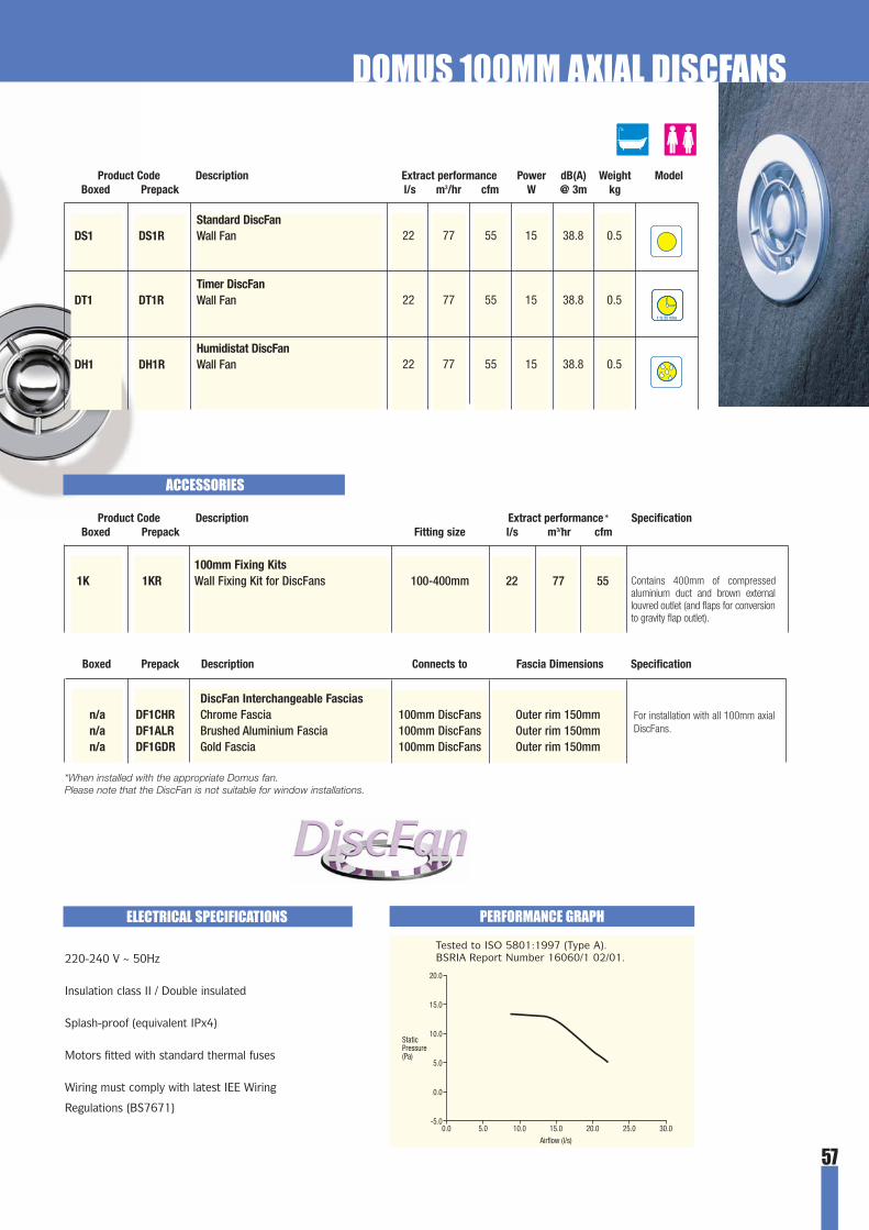
57
Standard DiscFanDS1 DS1R Wall Fan
Timer DiscFanDT1 DT1R Wall Fan
Humidistat DiscFanDH1 DH1R Wall Fan
Product Code Description Extract performance Power dB(A) Weight ModelBoxed Prepack l/s m3/hr cfm W @ 3m kg
22 77 55 15 38.8 0.5
22 77 55 15 38.8 0.5
22 77 55 15 38.8 0.5
1 to 25 mins
ACCESSORIES
PERFORMANCE GRAPHELECTRICAL SPECIFICATIONS
220-240 V ~ 50Hz
Insulation class II / Double insulated
Splash-proof (equivalent IPx4)
Motors fitted with standard thermal fuses
Wiring must comply with latest IEE Wiring
Regulations (BS7671)
Tested to ISO 5801:1997 (Type A). BSRIA Report Number 16060/1 02/01.
Product Code Description Extract performance* SpecificationBoxed Prepack Fitting size l/s m3/hr cfm
100mm Fixing Kits1K 1KR Wall Fixing Kit for DiscFans 100-400mm 22 77 55 Contains 400mm of compressed
aluminium duct and brown externallouvred outlet (and flaps for conversionto gravity flap outlet).
Boxed Prepack Description Connects to Fascia Dimensions Specification
DiscFan Interchangeable Fasciasn/a DF1CHR Chrome Fascia 100mm DiscFans Outer rim 150mm n/a DF1ALR Brushed Aluminium Fascia 100mm DiscFans Outer rim 150mmn/a DF1GDR Gold Fascia 100mm DiscFans Outer rim 150mm
For installation with all 100mm axialDiscFans.
*When installed with the appropriate Domus fan.Please note that the DiscFan is not suitable for window installations.
DOMUS 100MM AXIAL DISCFANS

58
DOMUS 100MM CENTRIFUGAL FANS
● Exceeds Building Regulations for bathrooms andtoilets. P1C/T1C also exceeds regulations for utility rooms
● Suitable for wall or ceiling installation
● For long ducting runs
● Integral back draft flap
● IPx4 Splash-proof rating
● Tough white high gloss ABS (fire retardant and UV stabilised)
● Quick and easy installation
● Three year guarantee
The DOMUS 100mm centrifugal fans are
versatile and powerful units made from safe,
durable, easily cleaned high gloss ABS.
Suitable for wall or ceiling installation.
Model options include: Pull-cord Switch and
Timer. The economy version is only available
as a timer version.
The 100mm range exceeds the Building
Regulation requirement of 30 l/s for utility
rooms, although the economy version only
exceeds the requirement of 15 l/s for
bathrooms.
Centrifugal fans are designed for air
movement over long distances as the air
enters the impeller in an axial direction and
leaves it in a radial direction. This creates
high pressure enabling air to travel quicker
and further. Domus centrifugal fans can be
used for long duct runs of between 10-15m.
CENTRIFUGAL FANS
A centrifugal fan recess mounted (T1C).
Economy centrifugal fan (T1EC).

59
DOMUS 100MM CENTRIFUGAL FANS
PERFORMANCE GRAPH
Product Code Description Extract performance Power dB(A) Weight ModelBoxed Prepack l/s m3/hr cfm W @ 3m kg
31 111 65 30 55 1.5
31 111 65 30 55 1.5
27 98 57 30 41 0.8
Pull Switch FanP1C n/a Wall / Ceiling Fan
Timer FanT1C n/a Wall / Ceiling Fan
Economy Timer FanT1EC n/a Wall / Ceiling Fan
ELECTRICAL SPECIFICATIONS
220-240 V ~ 50Hz
Insulation class II / Double insulated
Splash-proof (equivalent IPx4)
Motors fitted with standard thermal fuses
Wiring must comply with latest IEE Wiring
Regulations (BS7671)
162199
181
217
11226
97
4 to 631 to 33
85 35
72
72
DIMENSIONS
150 ø98
150 85 55
25.020.015.0
Airflow (l/s)
StaticPressure(Pa)
5.0 10.0 30.0
125.0
100.0
75.0
50.0
25.0
P1C/T1C
T1EC
1 to 25 mins
3 to 15 mins
ACCESSORIES
Boxed Prepack Description Fitting size Specification
100mm Centrifugal Fan Boxes2CB n/a Fan box for P1C/T1C to PolyVent 225 To fit 234 x 29mm ducting
3CB n/a Fan box for P1C/T1C to PolyVent 300 To fit 308 x 29mm ducting
Connects surface mounted centrifugal fans (P1C/T1C ONLY) toDomus PolyVent 225 ducting without the need for additionaladapters. Helps to provide optimum airflow conditions.
Connects surface mounted centrifugal fans (P1C/T1C ONLY) toDomus PolyVent 300 ducting without the need for additionaladapters. Helps to provide optimum airflow conditions.
P1C/T1Conly
All measurements in mm. Drawings not to scale.
P1C/T1C T1EC
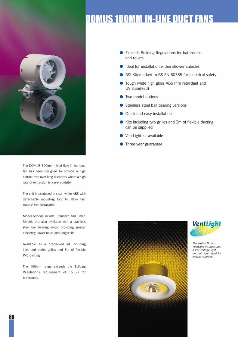
60
DOMUS 100MM IN-LINE DUCT FANS
● Exceeds Building Regulations for bathrooms and toilets
● Ideal for installation within shower cubicles
● BSI Kitemarked to BS EN 60335 for electrical safety
● Tough white high gloss ABS (fire retardant and UV stabilised)
● Two model options
● Stainless steel ball bearing versions
● Quick and easy installation
● Kits including two grilles and 3m of flexible ducting can be supplied
● VentLight kit available
● Three year guarantee
The DOMUS 100mm mixed flow in-line duct
fan has been designed to provide a high
extract rate over long distances where a high
rate of extraction is a prerequisite.
The unit is produced in clean white ABS with
detachable mounting foot to allow fast
trouble free installation.
Model options include: Standard and Timer.
Models are also available with a stainless
steel ball bearing motor providing greater
efficiency, lower noise and longer life.
Available as a prepacked kit including
inlet and outlet grilles and 3m of flexible
PVC ducting.
The 100mm range exceeds the Building
Regulations requirement of 15 l/s for
bathrooms.
The stylish DomusVentLight incorporatesa low voltage lightand air vent. Ideal forshower cubicles.

61
DOMUS 100MM IN-LINE DUCT FANS
Product Code Description Extract performance Power dB(A) Weight Model LightBoxed Prepack l/s m3/hr cfm W @ 3m kg
1 to 25 mins
17 58 36 15 - 0.5
17 58 36 15 - 0.5
- - - 15 - 0.5
- - - 15 - 0.5
- - - 15 - 0.5
- - - 15 - 0.5
- - - 15 - 0.5
17 58 36 15 - 0.5
17 58 36 15 - 0.5
- - - 15 - 0.5
- - - 15 - 0.5
- - - 15 - 0.5
- - - 15 - 0.5
- - - 15 - 0.5
Standard Duct FansS1D n/a Duct Fan
SB1D n/a Duct Fan with Ball Bearing Motor
S1DK S1DKR Duct Fan & Ceiling Kit
Standard VentLight KitsLS1DK LS1DKR Duct Fan & VentLight Ceiling Kit - White
LS1DKCH LS1DKCHR Duct Fan & VentLight Ceiling Kit - Chrome
LS1DKGD LS1DKGDR Duct Fan & VentLight Ceiling Kit - Gold
LS1DKAL LS1DKALR Duct Fan & VentLight Ceiling Kit - Brushed Aluminium
Timer Duct FansT1D n/a Duct Fan
TB1D n/a Duct Fan with Ball Bearing Motor
T1DK T1DKR Duct Fan & Ceiling Kit
Timer VentLight KitsLT1DK LT1DKR Duct Fan & VentLight Ceiling Kit -
White
LT1DKCH LT1DKCHR Duct Fan & VentLight Ceiling Kit -Chrome
LT1DKGD LT1DKGDR Duct Fan & VentLight Ceiling Kit -Gold
LT1DKAL LT1DKALR Duct Fan & VentLight Ceiling Kit -Brushed Aluminium
Ceiling kit performance figures cannot be given as they vary on theinstallation.
Ceiling kits are supplied with inlet, 3m of compressed PVC flexibleduct, brown louvred outlet (and flaps for conversion to gravity flapoutlet) and all necessary fixings.
VentLight contains 12V 35W halogen floodlight with cover lens. Kitsinclude 12V 60W transformer.
Boxed Prepack Description Fitting size External Dimensions Specification
100mm VentLight inc. 12V TransformerLV1 n/a White 100mm o.d. Outer rim 150mmLV1CH n/a Chrome 100mm o.d. Outer rim 150mmLV1AL n/a Brushed Aluminium 100mm o.d. Outer rim 150mmLV1GD n/a Gold 100mm o.d. Outer rim 150mm
12V 35W Halogen Floodlight with coverlens. Includes 12V 60W electronictransformer suitable for 12V Halogenlamps.
ACCESSORIES
1 to 25 mins
S E L V R A T E D
S E L V R A T E D
WARNING! VentLights must be installedin conjunction with an in-line duct fan

62
DIMENSIONS
All measurements in mm. Drawings not to scale.
In-line Duct Fan and Ceiling Kit comes with louvred outlet andoptional gravity flaps.
The DOMUS VentLight is a stylish SELV rated
air inlet featuring an integral 12V halogen
floodlight. It is ideal for safe installation in the
bath/shower room and can be installed within
the shower cubicle (zone 1). The VentLight
can be supplied as a kit complete with
transformer, in-line duct fan, flexible duct and
external wall outlet. The VentLight is available
in white, chrome, gold and aluminium.
The VentLight with 12V transformer is also
available with its own without the fan and
ceiling kit (see page 61).
100mm VentLight
100mm In-line Fan
DOMUS 100MM IN-LINE DUCT FANS

63
PERFORMANCE GRAPH ELECTRICAL SPECIFICATIONS
Tested to ISO 5801:1997 (Type A). BSRIA Report Number 14404/1 03/99.
220-240 V ~ 50Hz
Insulation class II / Double insulated
Drip-proof (equivalent IPx2)
Motors fitted with standard thermal fuses
Wiring must comply with latest IEE Wiring
Regulations (BS7671)
VentLight 12V 35W Halogen flood light with covered
lens - kits supplied with 60W transformer.
A typical installation of an in-line mixed flow
fan. The mixed flow blade design enables
effective extraction up to 4m. In-line fans are
concealed in the loft or ceiling void.
A condensation trap is recommended if
the ducting is installed vertically in an unheated
roof void (Domus ref: 497 see Ducting section
pages 13 and 27).
DOMUS 100MM IN-LINE DUCT FANS
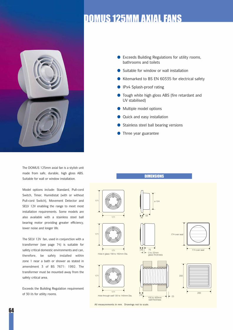
64
DOMUS 125MM AXIAL FANS
The DOMUS 125mm axial fan is a stylish unit
made from safe, durable, high gloss ABS.
Suitable for wall or window installation.
Model options include: Standard, Pull-cord
Switch, Timer, Humidistat (with or without
Pull-cord Switch), Movement Detector and
SELV 12V enabling the range to meet most
installation requirements. Some models are
also available with a stainless steel ball
bearing motor providing greater efficiency,
lower noise and longer life.
The SELV 12V fan, used in conjunction with a
transformer (see page 74) is suitable for
safety critical domestic environments and can,
therefore, be safely installed within
zone 1 near a bath or shower as stated in
amendment 3 of BS 7671: 1992. The
transformer must be mounted away from the
safety critical area.
Exceeds the Building Regulation requirement
of 30 l/s for utility rooms.
● Exceeds Building Regulations for utility rooms, bathrooms and toilets
● Suitable for window or wall installation
● Kitemarked to BS EN 60335 for electrical safety
● IPx4 Splash-proof rating
● Tough white high gloss ABS (fire retardant and UV stabilised)
● Multiple model options
● Quick and easy installation
● Stainless steel ball bearing versions
● Three year guarantee
DIMENSIONS
All measurements in mm. Drawings not to scale.

65
1 to 25 mins
DOMUS 125MM AXIAL FANS
Standard FansS12 n/a Wall FanSB12 n/a Wall Fan with Ball Bearing Motor
Pull Switch FansP12 n/a Wall FanPB12 n/a Wall Fan with Ball Bearing Motor
Timer FansT12 n/a Wall FanTB12 n/a Wall Fan with Ball Bearing Motor
Movement Detector FansM12 n/a Wall FanMB12 n/a Wall Fan with Ball Bearing Motor
Humidistat FanH12 n/a Wall Fan
Humidistat/Pull Switch FanHP12 n/a Wall Fan
SELV 12V FanSL12 n/a Wall Fan
Requires 12V transformer (see page 74)
Product Code Description Extract performance Power dB(A) Weight ModelBoxed Prepack l/s m3/hr cfm W @ 3m kg
49 176 103 25 47.1 0.849 176 103 25 47.1 0.8
49 176 103 25 47.1 0.849 176 103 25 47.1 0.8
49 176 103 25 47.1 0.849 176 103 25 47.1 0.8
49 176 103 25 47.1 0.849 176 103 25 47.1 0.8
49 176 103 25 47.1 0.8
49 176 103 25 47.1 0.8
49 176 103 25 47.1 0.8
PERFORMANCE GRAPHELECTRICAL SPECIFICATIONS
Tested to ISO 5801:1997 (TYPE A). BSRIA Report Number115277/1.
220-240 V ~ 50Hz (SELV versions 12 V ~ 50Hz)
Insulation class II / Double insulated
Splash-proof (equivalent IPx4)
Motors fitted with standard thermal fuses (SELV
versions motor fitted with auto-reset thermal cutouts)
Wiring must comply with latest IEE Wiring
Regulations (BS7671)
S E L V R A T E D
ACCESSORIES
Product Code Description Extract performance* SpecificationBoxed Prepack Fitting size l/s m3/hr cfm
125mm Fixing Kits
12K n/a Wall Fixing Kit for 125mm axial fans 100-400mm 45 164 96
12W n/a Window Fixing Kit for 125mm axial fans 3-22mm 39 140 82
Contains 400mm of compressed aluminiumduct and brown external louvred outlet.
Contains window gravity flap outlet, sealand fixings.
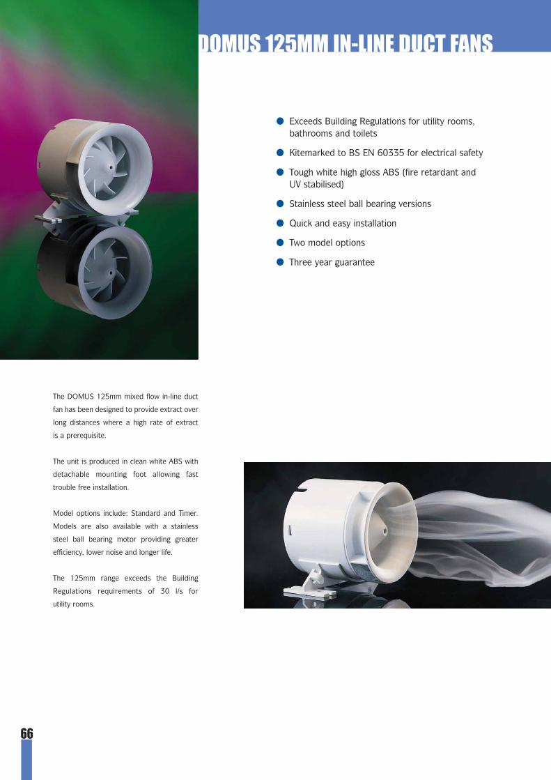
66
DOMUS 125MM IN-LINE DUCT FANS
● Exceeds Building Regulations for utility rooms,bathrooms and toilets
● Kitemarked to BS EN 60335 for electrical safety
● Tough white high gloss ABS (fire retardant and UV stabilised)
● Stainless steel ball bearing versions
● Quick and easy installation
● Two model options
● Three year guarantee
The DOMUS 125mm mixed flow in-line duct
fan has been designed to provide extract over
long distances where a high rate of extract
is a prerequisite.
The unit is produced in clean white ABS with
detachable mounting foot allowing fast
trouble free installation.
Model options include: Standard and Timer.
Models are also available with a stainless
steel ball bearing motor providing greater
efficiency, lower noise and longer life.
The 125mm range exceeds the Building
Regulations requirements of 30 l/s for
utility rooms.

67
DOMUS 125MM IN-LINE DUCT FANS
DIMENSIONS
Product Code Description Extract performance Power dB(A) Weight ModelBoxed Prepack l/s m3/hr cfm W @ 3m kg
31 112 66 25 - 0.731 112 66 25 - 0.7
31 112 66 25 - 0.731 112 66 25 - 0.7
Standard Duct FansS12D n/a Duct FanSB12D n/a Duct Fan with Ball Bearing Motor
Timer Duct FansT12D n/a Duct FanTB12D n/a Duct Fan with Ball Bearing Motor
PERFORMANCE GRAPHELECTRICAL SPECIFICATIONS
Tested to ISO 5801:1997 (TYPE A). 220-240 V ~ 50Hz
Insulation class II / Double insulated
Drip-proof (equivalent IPx2)
Motors fitted with standard thermal fuses
Wiring must comply with latest
IEE Wiring Regulations (BS7671)
1 to 25 mins
ACCESSORIES
Product Code Description SpecificationBoxed Prepack Fitting size
125mm Fixing Kits12DK n/a Ceiling Kit for 125mm in-line fans 3m Contains white internal and brown external
outlet, 3m of flexible hose and fixings.
All measurements in mm. Drawings not to scale.

68
DOMUS 150MM AXIAL FANS
● Exceeds Building Regulations for kitchens, utility rooms and large bathrooms
● Window or wall fixing options
● BSI Kitemarked to BS EN 60335 for electrical safety
● IPx4 Splash-proof rating
● Tough white high gloss ABS (fire retardant and UV stabilised)
● Stainless steel ball bearing versions
● Quick and easy installation
● Multiple model options
● Three year guarantee
The DOMUS 150mm axial fan is a stylish
unit made from safe, durable, easily cleaned
high gloss ABS. Suitable for wall or window
installation.
Model options include: Standard, Pull-cord
Switch, Timer, Humidistat (with or without
Pull-cord Switch), Movement Detector, Auto
Shutter and SELV 12V enabling the range to
meet most installation requirements. Some
models are also available with a stainless steel
ball bearing motor providing greater
efficiency, lower noise and longer life.
The SELV 12V fan used in conjunction with a
Domus transformer (see page 74) is suitable
for safety critical domestic environments
and can, therefore, be safely installed within
zone 1 near a bath or shower, as stated
in amendment 3 of BS7671:1992. The
transformer must be mounted away from the
source of water spray and out of the safety
critical area.
The 150mm range exceeds the Building
Regulation requirement of 60 l/s for kitchens.
The Domus Auto-Shutter fan is ideal for exposed, cold, dusty or smoky environments, when back draft prevention is vital.
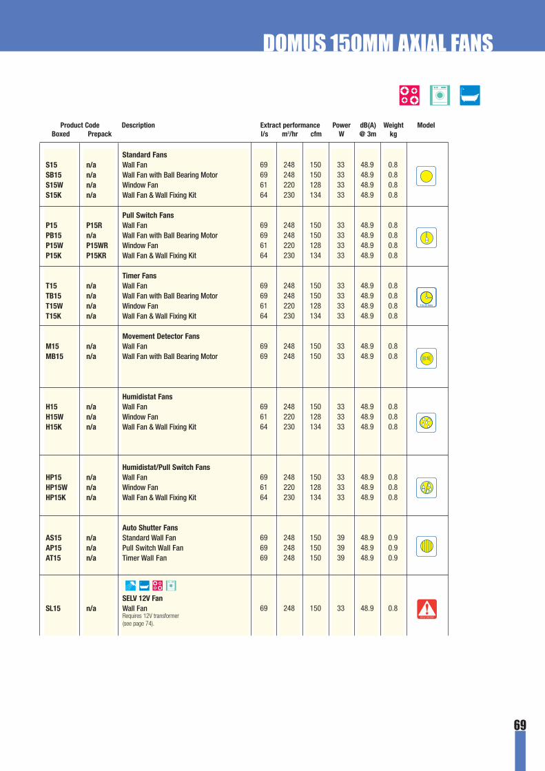
69
S E L V R A T E D
1 to 25 mins
DOMUS 150MM AXIAL FANS
Standard FansS15 n/a Wall FanSB15 n/a Wall Fan with Ball Bearing MotorS15W n/a Window FanS15K n/a Wall Fan & Wall Fixing Kit
Pull Switch FansP15 P15R Wall FanPB15 n/a Wall Fan with Ball Bearing MotorP15W P15WR Window FanP15K P15KR Wall Fan & Wall Fixing Kit
Timer FansT15 n/a Wall FanTB15 n/a Wall Fan with Ball Bearing MotorT15W n/a Window FanT15K n/a Wall Fan & Wall Fixing Kit
Movement Detector FansM15 n/a Wall FanMB15 n/a Wall Fan with Ball Bearing Motor
Humidistat FansH15 n/a Wall FanH15W n/a Window FanH15K n/a Wall Fan & Wall Fixing Kit
Humidistat/Pull Switch FansHP15 n/a Wall FanHP15W n/a Window FanHP15K n/a Wall Fan & Wall Fixing Kit
Auto Shutter FansAS15 n/a Standard Wall FanAP15 n/a Pull Switch Wall FanAT15 n/a Timer Wall Fan
SELV 12V Fan SL15 n/a Wall Fan
Product Code Description Extract performance Power dB(A) Weight ModelBoxed Prepack l/s m3/hr cfm W @ 3m kg
69 248 150 33 48.9 0.869 248 150 33 48.9 0.861 220 128 33 48.9 0.864 230 134 33 48.9 0.8
69 248 150 33 48.9 0.869 248 150 33 48.9 0.861 220 128 33 48.9 0.864 230 134 33 48.9 0.8
69 248 150 33 48.9 0.869 248 150 33 48.9 0.861 220 128 33 48.9 0.864 230 134 33 48.9 0.8
69 248 150 33 48.9 0.869 248 150 33 48.9 0.8
69 248 150 33 48.9 0.861 220 128 33 48.9 0.864 230 134 33 48.9 0.8
69 248 150 33 48.9 0.861 220 128 33 48.9 0.864 230 134 33 48.9 0.8
69 248 150 39 48.9 0.969 248 150 39 48.9 0.969 248 150 39 48.9 0.9
69 248 150 33 48.9 0.8Requires 12V transformer(see page 74).

70
PERFORMANCE GRAPH
ELECTRICAL SPECIFICATIONS
Tested to ISO 5801:1997 (Type A). BSRIA Report Number 14404/1 03/99.
220-240 V ~ 50Hz (SELV versions 12 V ~ 50Hz)
Insulation class II / Double insulated
Splash-proof (equivalent IPx4)
Motors fitted with standard thermal fuses
(SELV versions motor fitted with auto-reset thermal
cutouts)
Wiring must comply with latest IEE Wiring
Regulations (BS7671)
SELV fans provide safety from intense condensation build up.
DOMUS 150MM AXIAL FANS

ACCESSORIES
Auto Shutter Fan
DIMENSIONS
All measurements in mm. Drawings not to scale.
Window fan installation
Product Code Description Extract performance* SpecificationTrade Prepack Fitting size l/s m3/hr cfm
150mm Fixing Kits15K 15KR Wall Fixing Kit for 150mm axial fans 100-400mm 64 230 134
15W 15WR Window Fixing Kit for 150mm axial fans 3-22mm 61 220 128
Contains 400mm of compressed aluminiumduct and brown external louvred outlet.
Contains window gravity flap outlet, sealand fixings.
* when installed with appropriate Domus fan.
DOMUS 150MM AXIAL FANS
Boxed Prepack Description Connects to External Dimensions Specification
150mm Interchangeable Fasciasn/a F15CHR Chrome 150mm axial fan 201 x 201mmn/a F15ALR Brushed Aluminium 150mm axial fan 201 x 201mmn/a F15GDR Gold 150mm axial fan 201 x 201mm
For installation with all 150mm axialfans except HP (Humidistat with PullSwitch), M (Movement Detector) and A(Auto Shutter) models.
Product Code Description Extract performance* SpecificationBoxed Prepack Fitting size l/s m3/hr cfm
71

72
DOMUS 150MM IN-LINE DUCT FANS
● Exceeds Building Regulations for kitchens, utility rooms and large bathrooms
● BSI Kitemarked to BS EN 60335 for electrical safety
● Tough white high gloss ABS (fire retardant and UV stabilised)
● Stainless steel ball bearing versions
● Quick and easy installation
● Two model options
● Three year guarantee
The DOMUS 150mm mixed flow in-line duct
fan has been designed to provide extract over
long distances where a high rate of extract is
a prerequisite.
The unit is produced in clean white ABS with
detachable mounting foot allowing fast
trouble free installation.
Models include: Standard and Timer versions.
Models are also available with a stainless
steel ball bearing motor providing greater
efficiency, lower noise and longer life.
The 150mm range exceeds the Building
Regulations requirements of 60 l/s for
kitchens.
The Domus in-line duct fans utilise a mixed
flow blade designed for air movement over
medium distances (2 to 4m). A mixed flow
impeller combines the features of a
centrifugal and normal axial fan and the
higher pressure generated allows it to
move air over longer distances.
IN-LINE MIXED FLOW FANS

73
DOMUS 150MM IN-LINE DUCT FANS
Product Code Description Extract performance Power dB(A) Weight ModelBoxed Prepack l/s m3/hr cfm W @ 3m kg
62 224 130 33 - 0.762 224 130 33 - 0.7
62 224 130 33 - 0.762 224 130 33 - 0.7
PERFORMANCE GRAPH
DIMENSIONS
ELECTRICAL SPECIFICATIONS
Tested to ISO 5801:1997 (Type A).
Standard Duct FansS15D n/a Duct FanSB15D n/a Duct Fan with Ball Bearing Motor
Timer Duct FansT15D n/a Duct FanTB15D n/a Duct Fan with Ball Bearing Motor
220-240 V ~ 50Hz
Insulation class II / Double insulated
Drip-proof (equivalent IPx2)
Motors fitted with standard thermal fuses
Wiring must comply with latest IEE Wiring
Regulations (BS7671)
All measurements in mm. Drawings not to scale.
1 to 25 mins
ACCESSORIES
Product Code Description SpecificationBoxed Prepack Fitting size
150mm Fixing Kits15DK n/a Ceiling Kit for 150mm in-line fans 3m Contains white internal and brown external
outlet, 3m of flexible hose and fixings.

74
Product Code Description ModelBoxed Prepack
DOMUS 12 VOLT TRANSFORMERS
VS n/a 12 Volt Transformer - StandardTransformers are designed for remote operation.
VP n/a 12 Volt Transformer - Pull SwitchTransformers have the addition of a pull-cord for manual operation.
VT n/a 12 Volt Transformer - TimerTransformers are fitted with a remotely operated electronic overrun timer adjustable from 1 to 25 minutes.
VH n/a 12 Volt Transformer - HumidistatTransformers are fitted with an integral condensation control facility, adjustable between 60 and 80% RH,which enables the fan to continuously monitor humidity levels.These models also incorporate the overrun timer installed in VT models to facilitate remote operation.
VHP n/a 12 Volt Transformer - Humidistat/Pull SwitchModels have the same control options as the VH with the addition of a pull-cord switch and green LED indicator to provide a manual override.
All measurements in mm. Drawings not to scale.
DIMENSIONS
The DOMUS range of 12 Volt transformers
must be used when installing a Domus SELV
axial fan (see pages 54, 65 and 69).
Transformers must be mounted away from
any source of water spray and out of the
safety critical area (zone 0,1 or 2 as stated in
amendment 3 of BS7671:1992).
The transformers are fitted with multiple
control options to suit the whole Domus SELV
range of fans and incorporate a green LED to
indicate that the system is in operation.
A typical installation of a Domus VS 12 Volt Transformer
Transformers are available in retail packaging with a SELV fan and complete installation kit - see page 54 for details.
S E L V R A T E D
1 to 25 mins
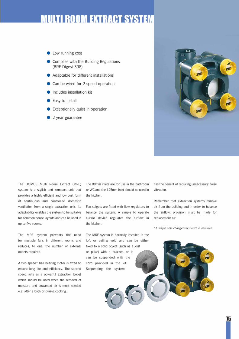
75
The DOMUS Multi Room Extract (MRE)
system is a stylish and compact unit that
provides a highly efficient and low cost form
of continuous and controlled domestic
ventilation from a single extraction unit. Its
adaptability enables the system to be suitable
for common house layouts and can be used in
up to five rooms.
The MRE system prevents the need
for multiple fans in different rooms and
reduces, to one, the number of external
outlets required.
A two speed* ball bearing motor is fitted to
ensure long life and efficiency. The second
speed acts as a powerful extraction boost
which should be used when the removal of
moisture and unwanted air is most needed
e.g. after a bath or during cooking.
The 80mm inlets are for use in the bathroom
or WC and the 125mm inlet should be used in
the kitchen.
Fan spigots are fitted with flow regulators to
balance the system. A simple to operate
cursor device regulates the airflow in
the kitchen.
The MRE system is normally installed in the
loft or ceiling void and can be either
fixed to a solid object (such as a joist
or pillar) with a bracket, or it
can be suspended with the
cord provided in the kit.
Suspending the system
has the benefit of reducing unnecessary noise
vibration.
Remember that extraction systems remove
air from the building and in order to balance
the airflow, provision must be made for
replacement air.
*A single pole changeover switch is required.
● Low running cost
● Complies with the Building Regulations (BRE Digest 398)
● Adaptable for different installations
● Can be wired for 2 speed operation
● Includes installation kit
● Easy to install
● Exceptionally quiet in operation
● 2 year guarantee
MULTI ROOM EXTRACT SYSTEM

SYSTEM 100
76
300
0
250
200
150
100
0.0 5.0 100 150 200 300 400
StaticPressure(Pa)
Airflow (m3/h)
50
250 350
LowSpeed
HighSpeed
DIMENSIONS & PERFORMANCE GRAPH
dimensions in mm
The system comes supplied as a kit with:
● 4 x 6m lengths of 80mm dia.
PVC flexible hose
● 2 x 6m lengths of 125mm dia.
PVC flexible hose
● 4 x 80mm dia. inlet (white)
● 1 x 125mm dia. inlet (white)
● Suspension cord
● Installation instructions
N.B. External outlet is not included. Please refer to the Ducting section (pages 9-13 for options).
The internal fan system of the unit is of the external rotor motor type
designed for durability with low maintenance levels. The impeller generates
high pressure levels to overcome duct resistance, but also minimises indoor
sound levels to almost inaudible levels.
MULTI ROOM EXTRACT SYSTEM
Product Code Description Extract performance Power Weight ElectricalBoxed Prepack l/s m3/hr cfm W kg Specification
58 210 122 272.4103 370 216 90
Multi-Room Extractor KitMREK n/a Two speed operation
Low SpeedHigh Speed
Electricity Supply 220 - 240V~50 Hz
The Domus MREK is only available for sale within the British Isles.
5900 Gravity Flap Outlet 5902 Cowled Outlet 5904 Louvred Grille

77
● Exceptional value for money
● Exceeds Building Regulations for bathrooms and toilets
● Wall fixing option
● IPx4 Splash-proof rating
● Three model options
● Easy installation
● Three year guarantee
The ELF fan range is a new generation
of economy extractor fan. It provides high
performance and offers exceptional value
for money.
The ELF has been designed with ease of
installation and simplicity in mind, making it
extremely contractor friendly. It is also discreet
and has a footprint of only 140mm x 140mm.
ELF can be installed in bathrooms or WCs,
as it exceeds the Building Regulations for these
rooms and can be wall or ceiling mounted.
Models include: Standard, Timer and Humidistat
versions.
Available in robust boxes with clear colour coded
model identification labels it is suitable for
installation with Domus ducting components and
fan accessories.
ELF FANS
£££Low Cost No FrillsELF is a ‘no frills’ range that still provides the basic
requirements for a simple domestic installation
and, of course, exceeds the Building Regulations.
An excellent alternative to the higher specification
standard Domus range of fans.
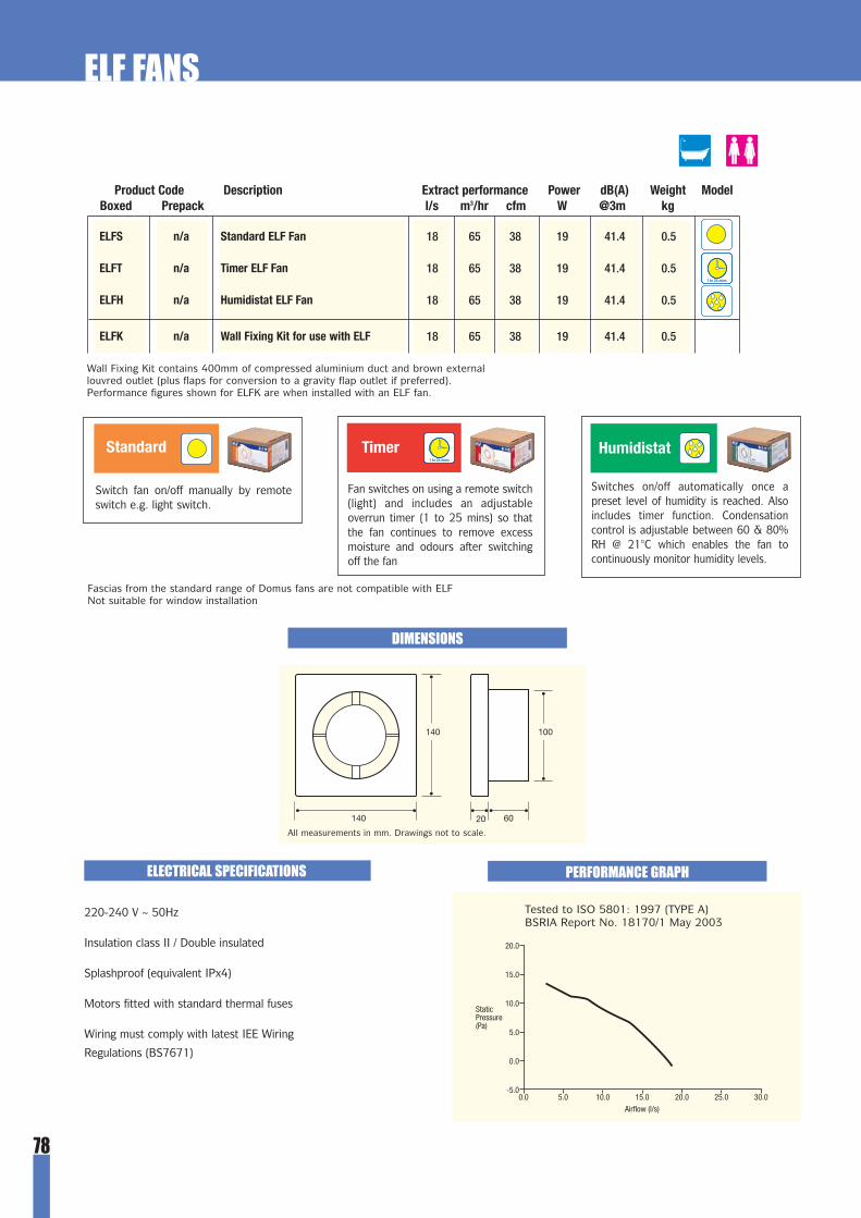
78
20.0
-5.0
15.0
10.0
5.0
0.0
0.0 5.0 10.0 15.0 20.0 25.0 30.0
StaticPressure(Pa)
Airflow (l/s)
Tested to ISO 5801: 1997 (TYPE A) BSRIA Report No. 18170/1 May 2003
Wall Fixing Kit contains 400mm of compressed aluminium duct and brown externallouvred outlet (plus flaps for conversion to a gravity flap outlet if preferred).Performance figures shown for ELFK are when installed with an ELF fan.
Fascias from the standard range of Domus fans are not compatible with ELFNot suitable for window installation
PERFORMANCE GRAPH
ELF FANS
Product Code Description Extract performance Power dB(A) Weight ModelBoxed Prepack l/s m3/hr cfm W @3m kg
18 65 38 19 41.4 0.5
18 65 38 19 41.4 0.5
18 65 38 19 41.4 0.5
18 65 38 19 41.4 0.5
ELFS n/a Standard ELF Fan
ELFT n/a Timer ELF Fan
ELFH n/a Humidistat ELF Fan
ELFK n/a Wall Fixing Kit for use with ELF
1 to 25 mins
1 to 25 mins
HumidistatTimerStandard
Switch fan on/off manually by remoteswitch e.g. light switch.
Fan switches on using a remote switch(light) and includes an adjustableoverrun timer (1 to 25 mins) so thatthe fan continues to remove excessmoisture and odours after switchingoff the fan
Switches on/off automatically once apreset level of humidity is reached. Alsoincludes timer function. Condensationcontrol is adjustable between 60 & 80%RH @ 21°C which enables the fan tocontinuously monitor humidity levels.
ELECTRICAL SPECIFICATIONS
220-240 V ~ 50Hz
Insulation class II / Double insulated
Splashproof (equivalent IPx4)
Motors fitted with standard thermal fuses
Wiring must comply with latest IEE Wiring
Regulations (BS7671)
DIMENSIONS
140 20 60
140 100
All measurements in mm. Drawings not to scale.
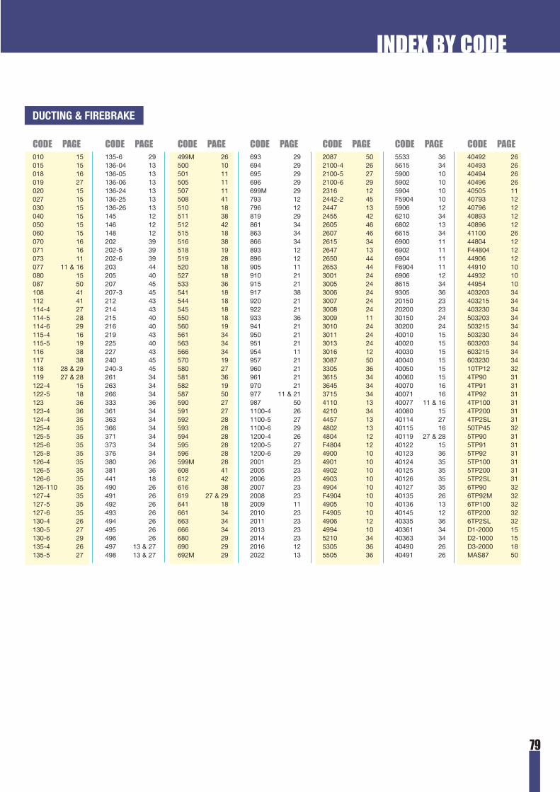
79
INDEX BY CODE
010 15015 15018 16019 27020 15027 15030 15040 15050 15060 15070 16071 16073 11077 11 & 16080 15087 50108 41112 41114-4 27114-5 28114-6 29115-4 16115-5 19116 38117 38118 28 & 29119 27 & 28122-4 15122-5 18123 36123-4 36124-4 35125-4 35125-5 35125-6 35125-8 35126-4 35126-5 35126-6 35126-110 35127-4 35127-5 35127-6 35130-4 26130-5 27130-6 29135-4 26135-5 27
135-6 29136-04 13136-05 13136-06 13136-24 13136-25 13136-26 13145 12146 12148 12202 39202-5 39202-6 39203 44205 40207 45207-3 45212 43214 43215 40216 40219 43225 40227 43240 45240-3 45261 34263 34266 34333 36361 34363 34366 34371 34373 34376 34380 26381 36441 18490 26491 26492 26493 26494 26495 26496 26497 13 & 27498 13 & 27
499M 26500 10501 11505 11507 11508 41510 18511 38512 42515 18516 38518 19519 28520 18527 18533 36541 18544 18545 18550 18560 19561 34563 34566 34570 19580 27581 36582 19587 50590 27591 27592 28593 28594 28595 28596 28599M 28608 41612 42616 38619 27 & 29641 18661 34663 34666 34680 29690 29692M 29
693 29694 29695 29696 29699M 29793 12796 12819 29861 34863 34866 34893 12896 12905 11910 21915 21917 38920 21922 21933 36941 21950 21951 21954 11957 21960 21961 21970 21977 11 & 21987 501100-4 261100-5 271100-6 291200-4 261200-5 271200-6 292001 232005 232006 232007 232008 232009 112010 232011 232013 232014 232016 122022 13
2087 502100-4 262100-5 272100-6 292316 122442-2 452447 132455 422605 462607 462615 342647 132650 442653 443001 243005 243006 243007 243008 243009 113010 243011 243013 243016 123087 503305 363615 343645 343715 344110 134210 344457 134802 134804 12F4804 124900 104901 104902 104903 104904 10F4904 104905 10F4905 104906 124994 105210 345305 365505 36
5533 365615 345900 105902 105904 10F5904 105906 126210 346802 136615 346900 116902 116904 11F6904 116906 128615 349305 3620150 2320200 2330150 2430200 2440010 1540020 1540030 1540040 1540050 1540060 1540070 1640071 1640077 11 & 1640080 1540114 2740115 1640119 27 & 2840122 1540123 3640124 3540125 3540126 3540127 3540135 2640136 1340145 1240335 3640361 3440363 3440490 2640491 26
40492 2640493 2640494 2640496 2640505 1140793 1240796 1240893 1240896 1241100 2644804 12F44804 1244906 1244910 1044932 1044954 10403203 34403215 34403230 34503203 34503215 34503230 34603203 34603215 34603230 3410TP12 324TP90 314TP91 314TP92 314TP100 314TP200 314TP2SL 3150TP45 325TP90 315TP91 315TP92 315TP100 315TP200 315TP2SL 316TP90 326TP92M 326TP100 326TP200 326TP2SL 32D1-2000 15D2-1000 15D3-2000 18MAS87 50
CODE PAGE CODE PAGE CODE PAGE CODE PAGE CODE PAGE CODE PAGE CODE PAGE
DUCTING & FIREBRAKE

80
1K 54 & 571KR 54 & 571W 541WR 5412DK 6712K 6512W 6515DK 7315K 7115KR 7115W 7115WR 712CB 593CB 59AP1 53AP15 69AS1 53AS15 69AT1 53AT15 69DF1ALR 57DF1CHR 57DF1GDR 57
DH1 57DH1R 57DS1 57DS1R 57DT1 57DT1R 57ELFH 78ELFK 78ELFS 78ELFT 78F15ALR 71F15CHR 71F15GDR 71F1ALR 54F1CHR 54F1GDR 54H1 53H12 65H15 69H15K 69H15W 69H1K 53H1KR 53
H1R 53H1W 53H1WR 53HL1VKR 54HP1 53HP12 65HP15 69HP15K 69HP15W 69HP1K 53HP1KR 53HP1R 53HP1W 53HP1WR 53HPL1VKR 54LS1DK 61LS1DKAL 61LS1DKALR 61LS1DKCH 61LS1DKCHR 61LS1DKGD 61LS1DKGDR 61LS1DKR 61
LT1DK 61LT1DKAL 61LT1DKALR 61LT1DKCH 61LT1DKCHR 61LT1DKGD 61LT1DKGDR 61LT1DKR 61LV1 61LV1AL 61LV1CH 61LV1GD 61M1 53M12 65M15 69MB1 53MB12 65MB15 69MREK 76P1 53P12 65P15 69P15K 69
P15KR 69P15R 69P15W 69P15WR 69P1C 59P1K 53P1KR 53P1R 53P1W 53P1WR 53PB1 53PB12 65PB15 69PL1VKR 54S1 53S12 65S12D 67S15 69S15D 73S15K 69S15W 69S1D 61S1DK 61
S1DKR 61S1K 53S1KR 53S1R 53S1W 53S1WR 53SB1 53SB12 65SB12D 67SB15 69SB15D 73SB1D 61SL1 54SL12 65SL15 69SL1VKR 54T1 53T12 65T12D 67T15 69T15D 73T15K 69T15W 69
T1C 59T1D 61T1DK 61T1DKR 61T1EC 59T1K 53T1KR 53T1R 53T1W 53T1WR 53TB1 53TB12 65TB12D 67TB15 69TB15D 73TB1D 61TL1VKR 54VH 74VHP 74VP 74VS 74VT 74
CODE PAGE CODE PAGE CODE PAGE CODE PAGE CODE PAGE CODE PAGE CODE PAGE
FANS
INDEX BY CODE
www.domusventilation.com
E & OE We reserve the right to alter product specification without prior notice