Embed Size (px)
Citation preview

DOOR MANUAL: INST-103-05 PART 1 of 2
RH GLIDER ENTRANCE ELECTRIC DOOR SYSTEM for TREKA-16/24 DDA
§ TDS DOOR SYSTEM INTRODUCTION § BASIC DOOR SYSTEM CHECK GUIDELINES § DOOR SYSTEM TESTING & FAULT FINDING § EXTERNAL ROTARY LOCK SYSTEM OPERATION
43 Broton Drive, Halstead, Essex, CO9 1HB. Tel: 01787 473000 Fax: 01787 477040 Email: [email protected] www.transportdoorsolutions.co.uk
INST-103-05 PT.1-2 @ Rev.1 copyright © 2016 Transport Door Solutions Ltd

TRANSPORT DOOR SYSTEM INTRODUCTION Transport Door Solutions door system is a most durable system. By drawing on technology gained world-wide on both bus and rail, TDS have created doors for the P.S.V. market that are tough, reliable, maintainable, easy to install and safe. The doors utilise specially designed aluminium extrusions, which make them more resistant to damage and vandalism. The basic overall design allows easy installation and adjustment which means lower installation and maintenance costs. Control systems available include: Pneumatic, Electro-Pneumatic or Electric & Manual operating door systems. Treka Door System Inward gliding door supplied as a fully assembled single leaf complete with nosing rubbers, bottom seals and guide rollers, with RH door shaft on which the door leaves pivots, The whole assembly is secured to the floor/step of the vehicle by M6 screws through slotted holes which allow for transverse adjustment. The bottom bearing element is nylon, for horizontal location only and does not take any downward loading, is free to move vertically inside the door shaft. The weight of the door leaf is loaded onto the door shaft, top and bottom arms the door shaft is suspended from the top bearing, which is part of the shelfplate mechanism. Since door leaves vary according to the coach builders requirements, identification and ordering of spare parts other than standard items, involves quoting the door serial number, plus a brief description of the part and/or where it is located. The door serial number is located on a TDS identification label on the upper interior side of the right hand door leaf. Please note that when identifying door parts, for RHD vehicle RH (No.1) door & LH (No.2) door as viewed from inside the vehicle looking out.
BASIC TERMINOLOGY >
RH Descending Handrail
Grab handle RH Doorshaft
Serial No. Label
Nosing Rubber
Bottom Bearing Behind door
Door Guide Bracket & Spindle
Inner Sabot Cover
Edging Rubber
Internal Emergency Lock Override Pull Handle
Leading Edge Trailing Edge
Bottom Steady Guide Shoe
Sph Rod End
Reed Switch Controls
Drive Crank Arm Gear Box & Drive Unit
Slide Clutch Override System
Drive Motor
Powered coated Steel Fabricated Shelf-plate.
Typical Electric Drive Unit
Typical Inward Glider Door
Slide Clutch Warning micro-switch

BASIC DOOR SYSTEM CHECK GUIDELINES TREKA-GLD042 RH SINGLE GLIDER ELECTRIC DOOR SYSTEM These doors are designed for ease of use and operation. The amount of moving parts has been kept to an absolute minimum, thus reducing the levels maintenance required. The following guidelines are our recommended minimum level of service / inspection. ◙ Service-Inspection Time Guide: 1st Check at 6 months then annually thereafter or when replacing a defective/damaged part. It is important that any components found to be damaged or defective at any time are replaced or repaired as soon as possible. Failure to do so could result in further damage to other components or loss of door operation. □ Manually open and close the door via slide clutch, O Checking that door is free running. O Ensure that Aperture seals, Nosing rubber, Door active flaps & Bottom guide pin are not restricting door movement. O Checking slide clutch is engaging with door in the fully closed position against aperture seals. O Adjust spring tension to suit operation if required (see details for standard setting). □ Check door-guide roller/spindle for clearance gap (3mm) and free movement in the integral track on underside of shelf-plate are dry and free from grease and the spindle is fully secured correctly. □ Check that all fasteners and bolts on door-leaves and shelf-plate are fully secured. □ Check all electrical connections, ensure cables are not snagging when manually opening door. □ Visually check all aperture seals, door frame & nosing rubber, handles, door-shaft for any damage and are secured correctly. □ Pivot & Bearings Lubrication as required. □ Check full function of lock system and Lubrication as required.
= Denotes Grease Lubrication. = Denotes Wet Lubrication. (Do Not Use WD40 Original for lubrication only use as cleaning agent)
□ Inner Sabot Cover: To remove cover pop out plastic screw caps, using poz bit screw driver , slacking off screws, then pull up cover vertically to remove.
WITH POWER SUPPLY ON □ Operate the doors to check door alignment also with the door in the fully closed position against aperture seals and Door is fully
open in a firm position. Adjust if necessary. (Note door guide spindle must be in the vertical position) □ Check the operation of the door using all open and close buttons located in the drivers console, above the doors and those positioned externally and hand brake interlock (auto close) □ Check reed-switch positions, with door closed and open position Adjust if necessary, with slide cutch fully engaged. □ Check step light active when operating door either by Manually or Electric drive method to fully open door.
External Rotary Lock. For fully operating details see instruction sheet HDL007T-J2-02
SAFETY NOTE: Before any checks are undertaken you may need to turn the power supply off to the door system via the circuit breaker switch if applicable. First, position door in the fully closed position.
RH Descending Handrail
Grab handle
RH Door-shaft
Door Serial No.
Leading Edge & Nosing Rubber
Bottom Bearing Behind door
Door guide Spindle &
Door guide Bracket
Inner Sabot Cover
Internal Emergency Lock OVERRIDE
Handle
Vertical Aperture Rubber seal
Trailing Edge & Rear Rubber
External Open Button
Spherical Rod End
Door Open Reed Switch
“E” Drive Unit Assy
Bottom Guide Pin & Guide Shoe
3mm Min Clearance
2-3mm Clearance
Lower Pivot Bearing
or Slide Rail (light lubrication)
Upper Pivot Bearing
Slide Clutch Warning micro-switch
Drive Crank Arm Shaft Top Bearing
# M12 Hex Nut
Door Closed Reed Switch
5mm Min When Door Is Fully Closed
Clutch Spring Setting 1. Electric Drive=15mm(+1.5 -0.0) 2. Manual Drive=11mm (+/- 1.0)
Cable Lug. 3mm Gap When the lock Pin
is Extended
Check For Grease on slide clutch arm
INST-103-03 @ Rev.1 1-1 Page
Horizontal Brush Seal
# Circlip & M16 washer
To remove “ E-Drive Unit Assy”. Mark up all plugs with matching No’s then disconnect. Manually half open door, remove # circlip & M16 washer from rear end then remove # M12 nut & washer from front end, lift off drive and remove for further inspection or replacement as required.
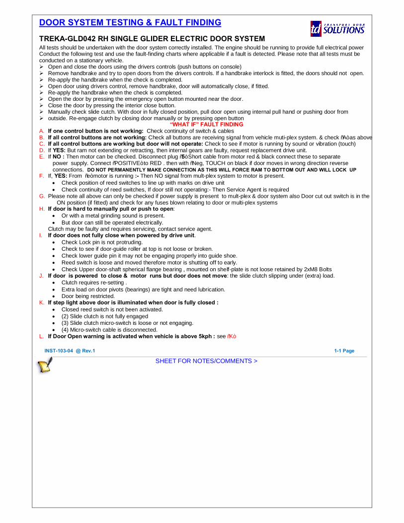
DOOR SYSTEM TESTING & FAULT FINDING TREKA-GLD042 RH SINGLE GLIDER ELECTRIC DOOR SYSTEM All tests should be undertaken with the door system correctly installed. The engine should be running to provide full electrical power Conduct the following test and use the fault-finding charts where applicable if a fault is detected. Please note that all tests must be conducted on a stationary vehicle. Ø Open and close the doors using the drivers controls (push buttons on console) Ø Remove handbrake and try to open doors from the drivers controls. If a handbrake interlock is fitted, the doors should not open. Ø Re-apply the handbrake when the check is completed. Ø Open door using drivers control, remove handbrake, door will automatically close, if fitted. Ø Re-apply the handbrake when the check is completed. Ø Open the door by pressing the emergency open button mounted near the door. Ø Close the door by pressing the interior close button. Ø Manually check slide cutch. With door in fully closed position, pull door open using internal pull hand or pushing door from Ø outside. Re-engage clutch by closing door manually or by pressing open button
“WHAT IF” FAULT FINDING A. If one control button is not working: Check continuity of switch & cables B. If all control buttons are not working: Check all buttons are receiving signal from vehicle muti-plex system. & check “A” as above C. If all control buttons are working but door will not operate: Check to see if motor is running by sound or vibration (touch) D. If YES: But ram not extending or retracting, then internal gears are faulty, request replacement drive unit. E. If NO : Then motor can be checked. Disconnect plug “5” Short cable from motor red & black connect these to separate
power supply. Connect “POSITIVE” to RED . then with “Neg, TOUCH on black if door moves in wrong direction reverse connections. DO NOT PERMANENTLY MAKE CONNECTION AS THIS WILL FORCE RAM TO BOTTOM OUT AND WILL LOCK UP
F. If, YES: From “e” motor is running :- Then NO signal from mult-plex system to motor is present. • Check position of reed switches to line up with marks on drive unit • Check continuity of reed switches, If door still not operating:- Then Service Agent is required
G. Please note all above can only be checked if power supply is present to mult-plex & door system also Door cut out switch is in the ON position (if fitted) and check for any fuses blown relating to door or multi-plex systems
H. If door is hard to manually pull or push to open: • Or with a metal grinding sound is present. • But door can still be operated electrically.
Clutch may be faulty and requires servicing, contact service agent. I. If door does not fully close when powered by drive unit.
• Check Lock pin is not protruding. • Check to see if door-guide roller at top is not loose or broken. • Check lower guide pin it may not be engaging properly into guide shoe. • Reed switch is loose and moved therefore motor is shutting off to early. • Check Upper door-shaft spherical flange bearing , mounted on shelf-plate is not loose retained by 2xM8 Bolts
J. If door is powered to close & motor runs but door does not move: the slide clutch slipping under (extra) load. • Clutch requires re-setting . • Extra load on door pivots (bearings) are tight and need lubrication. • Door being restricted.
K. If step light above door is illuminated when door is fully closed : • Closed reed switch is not been activated. • (2) Slide clutch is not fully engaged • (3) Slide clutch micro-switch is loose or not engaging. • (4) Micro-switch cable is disconnected.
L. If Door Open warning is activated when vehicle is above 5kph : see “K”
SHEET FOR NOTES/COMMENTS >
INST-103-04 @ Rev.1 1-1 Page

EXTERNAL ROTARY LOCK SYSTEM OPERATION HDL007T-J2 = Bottom panel mounted rotary lock system
1. TO LOCK DOOR: FROM OUTSIDE
With door in fully closed position and key slot in a horizontal position rotate handle Anti-clockwise. This will extend lock pin and lock door, handle will then spring return to a vertical position. Place key in lock then turn key only 90˚ Anti-clockwise to a vertical position and remove key. This will lock and prevent handle from rotating from outside.
2. TO UNLOCK DOOR: FROM OUTSIDE
Place key in lock then turn key only 90˚ Clockwise to horizontal position and remove key, Now turn rotary handle Clockwise, this will retract lock pin and unlock door. Rotary handle will then spring return to a vertical position. Door can now be power operated or manually pushed open from outside or pulled open from inside
(Do not use emergency “LOCK OVERRIDE” pull handle for this operation) 3. TO MANUALLY OPEN DOOR FROM OUTSIDE (ONLY WHEN DOOR IS UNLOCKED)
To unlock door as in item.2 Push door on left hand side, this will disengage slide clutch. With door open slightly. Push left side and pull right side door into a fully open position.
4. TO MANUALLY OPEN DOOR FROM INSIDE (ONLY WHEN DOOR IS UNLOCKED)
Push door on left hand side & Pull from right side using BLACK internal pull handle, This will disengage slide clutch and you will be able to open door fully.
5. TO MANUALLY CLOSE DOOR IF MANUALLY OPENED
Pull & push door to fully closed position snapping slide clutch into its engaged position, which should be heard. Now door can be locked as in item.1
6. TO OPEN DOOR IN A EMERGENCY FROM INSIDE WHEN DOOR LOCK IS ENGAGED
With the door closed and lock pin engaged (may be key locked too), Door can only be opened manually from inside the vehicle, by using the RED “LOCK OVERRIDE “ pull handle in a down ward direction. This will retract lock pin and release door, for manual open from inside & outside or power operation to open door
7. Rotary handle lock key can be removed In two positions when handle is locked & unlocked.
IMPORTANT NOTE: BEFORE POWERING UP VEHICLE With NO power supply to door drive system and open/close control buttons, with rotary handle unlocked and lock pin disengaged. A. Manually open by means of Push/Pull action, the door then must be manually closed after entering vehicle to
engage slide clutch correctly. Now POWER up vehicle and door can be operated normally by the drivers & remote control buttons
B. Door cannot be shut manually with door powered to fully open position. C. Door must not be power operated when lock pin is engaged or extended
HDL007T-J2-02. ISSUE: 4 – 09.05.2016 copyright © 2016 Transport Door Solutions Ltd
External Rotary Lock Handle.
LOCK OVERRIDE Internal Pull handle
Illustration shown on a Treka-16 RH Entrance Glider Door Mk-5 (Ref GLD042)
Lock Pin Engage Disengage
Lock Pin Disengage
BLACK Internal Pull handle

TYPICAL TOOL REQUIREMENTS & STANDARD TORQUE SETTINGS
SPANNERS ALLEN KEYS
Open & Closed Ended Hex & Ball Nose Ends
24, 23, 22, 19, 17, 16, 13,12, 10, 8, 7, 4, mm A/F 1.5, 2.0, 2.5, 3.0, 4.0, 5.0, 6.0, 8.0, 12. mm A/F
Adjustable Spanner Tee Bar Type
Up To 25mm Opening S-M-L 3.0, 4.0, 5.0, 6.0, 8.0.
Sockets
“SCREW DRIVERS BITS” MISCELLANEOUS
4mm Flat Blade Screwdrivers (S-M-L) Internal & External Circlip Pliers
No.PZ2 Pozi-Drive Screwdriver Pliers flat & tapered ends
No.PZ2 Pozi-Drive Bit Stanley Knife
No.PZ3 Pozi-Drive Bit Scissors
Hammer small Combination type
NUT TIGHTENING TORQUE
M6 7 Nm
M8 17 Nm
M10 36 Nm
M12 55 Nm
M14 80 Nm
M16 120 Nm
BOLT / SCREW TIGHTENING TORQUE
M6 12 Nm
M8 25 Nm
M10 52 Nm
M12 94 Nm
M16 90 Nm
M20 150 Nm

TDS Service Engineer Request Sheet
Report Number : SER Allocated by TDS
Operator: Date:
Location: Contact Name:
Tel. No:
Vehicle Type: Fleet/Body No:
Reg No: Mileage:
Warranty/ Chargeable? Customer Order
No/Warranty Ref:
OFFICE USE ONLY Nature Of Problem:
Cause:
Corrective Action Taken:
Parts Used:
Site time: Hrs: TDS Stock Issued Yes/no
Travel time: Hrs: Service Agent Stock Issued Yes/no
Total time: Hrs: Other Yes/no
Customer Sign Off: Date: Time:
Printed Name:
Service Engineer:
Service Agent:
NOTE IF PARTS NOT FOUND NOT TO BE DEFECTIVE AFTER INVESTIGATION, WE RESERVE THE RIGHT TO RECOVER
MATERIAL AND LABOUR COSTS