Embed Size (px)
Citation preview
ORCA PANIC EXIT DEVICEK13.11
K13
DOORS
01.06.2018
Waregemstraat 5 - 9870 Zulte - Belgium - T. +32 9 388 88 81 - F. +32 9 388 88 21 - [email protected] - www.sobinco.com
CONTENTS
1. General information ............................................................ K13.11.031.1. Standards EN 1125 and EN 179 K13.11.031.2. Panic exit lock functions B, D and E K13.11.041.3. Description of the functions K13.11.05
2. Panic exit lock ..................................................................... K13.11.082.1. Description and advantages K13.11.082.2. Technical characteristics K13.11.092.3. Multipoint lock with standard latch bolt K13.11.102.4. Short (K) and long (L) version K13.11.112.5. Single lock with standard latch bolt K13.11.122.6. Replacing and turning the latch bolt K13.11.132.7. Setting of the functions B, D and E K13.11.15
3. Short keeps ..........................................................................K13.11.163.1. General K13.11.163.2. With U-shaped faceplate K13.11.163.3. Withflatfaceplate K13.11.17
4. Long keeps .......................................................................... K13.11.184.1. With U-shaped faceplate K13.11.184.2. Withflatfaceplate K13.11.194.3. Shorter (K) and longer (L) version K13.11.20
5. Keeps with positioning piece ............................................. K13.11.21
6. Adjustment keeps ............................................................... K13.11.22
7. Casesinsyntheticmaterialforflatkeeps ......................... K13.11.23
8. Electric door opener n° 787-118 ........................................ K13.11.248.1. General characteristics K13.11.248.2. Function K13.11.248.3. Installation on faceplate K13.11.25
9. Section preparations .......................................................... K13.11.269.1. Locks K13.11.269.2. Keeps without electric strike K13.11.279.3. Keeps with electric strike K13.11.28
10. Operating devices ............................................................... K13.11.2910.1. With horizontal push bar n° 80200-70 and 80200-71 K13.11.2910.2. With door handle n° 80200-50(C)L (VI) K13.11.3710.3. Fixed external door knob n° 82106L VI K13.11.42
11. General guidelines .............................................................. K13.11.4311.1. Coverage documentation K13.11.4311.2. Application area K13.11.4311.3. Operating devices K13.11.4411.4. Inappropriate use K13.11.4511.5. General installation instructions K13.11.4611.6. Maintenance and checks K13.11.47
12. CE marking .......................................................................... K13.11.4812.1. With horizontal push bar (EN 1125) K13.11.4812.2. With door handle (EN 179) K13.11.49
K13.11.02 PANIC EXIT DEVICE
ORCA PANIC EXIT DEVICE
K13.11
1. General information1.1. Standards EN 1125 and EN 179
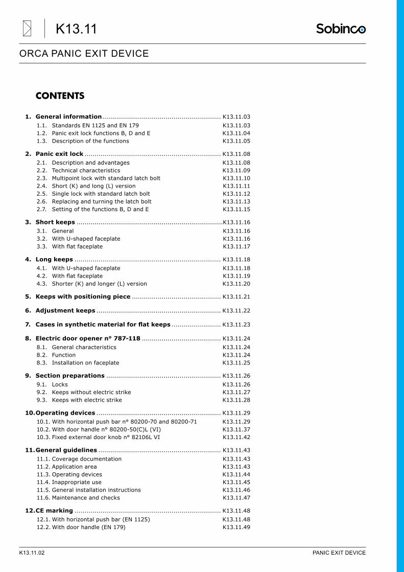
• Thetypeofroomandutilizationofthebuildingaredecisivewhenchoosingtherightexitpanicfittings.• TheEuropeanstandardsEN1125andEN179definethefittingsforpanicexitdoorsandemergencyexits.
EN 1125• Panic exit locks, operated by a
horizontal activation bar in accordance with standard EN 1125 are intended for use in buildings frequented by the general public.
• These panic exit devices ensure that persons who have panicked and are not acquainted with the escape routes and the functions of the door, can always get out of the building safely. In other words, the users have no advance knowledge of how to open the escape door.
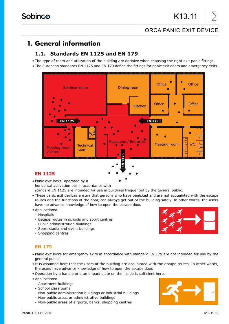
• Applications: - Hospitals - Escape routes in schools and sport centres - Public administration buildings - Sport stadia and event buildings - Shopping centres
EN 179• Panic exit locks for emergency exits in accordance with standard EN 179 are not intended for use by the
general public.• It is assumed here that the users of the building are acquainted with the escape routes. In other words,
the users have advance knowledge of how to open the escape door.• Operationbyahandleoraanimpactplateontheinsideissufficienthere.• Applications:
- Apartment buildings - School classrooms - Non-public administration buildings or industrial buildings - Non-public areas or administrative buildings - Non-public areas of airports, banks, shopping centres
Seminar room Dining room
Kitchen
Office Office
Office Office
Meeting roomMeeting room visitors
Reception / EntranceTechnical room
WC
WC
EN 179EN
112
5EN 1125
PANIC EXIT DEVICE K13.11.03
ORCA PANIC EXIT DEVICE
K13.11
1.2. Panic exit lock functions B, D and E
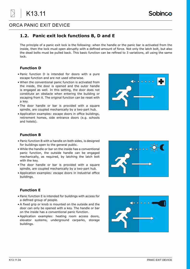
The principle of a panic exit lock is the following: when the handle or the panic bar is activated from the inside,thenthelockmustopenabruptlywithadefinedamountofforce.Notonlythelatchbolt,butalsothedeadboltsmustbepulledback.Thisbasicfunctioncanberefinedto3variations,allusingthesamelock.
Function D• Panic function D is intended for doors with a pure
escape function and are not used otherwise.• When the conventional panic function is activated from
the inside, the door is opened and the outer handle is engaged as well. In this setting, the door does not constitute an obstacle when entering the building or escaping from it. The original function can be reset with a key.
• The door handle or bar is provided with a square spindle, are coupled mechanically by a two-part hub.
• Applicationexamples:escapedoorsinofficebuildings,retirement homes, side entrance doors (e.g. schools and hotels).
Function B• Panic function B with a handle on both sides, is designed
for buildings open to the general public.• While the handle or bar on the inside has a conventional
panic function, the outside handle can be engaged mechanically, as required, by latching the latch bolt with the key.
• The door handle or bar is provided with a square spindle, are coupled mechanically by a two-part hub.
• Applicationexamples:escapedoorsinindustrialofficebuildings.
Function E• Panic function E is intended for buildings with access for adefinedgroupofpeople.
• Afixedgriporknobismountedontheoutsideandthedoor can only be opened with a key. The handle or bar on the inside has a conventional panic function.
• Application examples: heating room access doors, elevator systems, underground carparks, storage buildings.
K13.11.04 PANIC EXIT DEVICE
ORCA PANIC EXIT DEVICE
K13.11
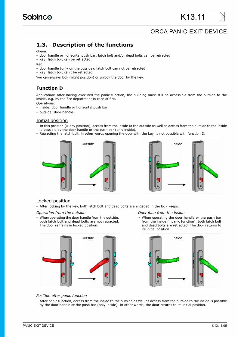
1.3. Description of the functionsGreen: - door handle or horizontal push bar: latch bolt and/or dead bolts can be retracted - key: latch bolt can be retracted
Red: - door handle (only on the outside): latch bolt can not be retracted - key: latch bolt can’t be retracted
You can always lock (night position) or unlock the door by the key.
Function DApplication: after having executed the panic function, the building must still be accessible from the outside to the inside,e.g.bythefiredepartmentincaseoffire.Operations: - inside: door handle or horizontal push bar - outside: door handle
Initial position - In this position (= day position), access from the inside to the outside as well as access from the outside to the inside is possible by the door handle or the push bar (only inside).
- Retracting the latch bolt, in other words opening the door with the key, is not possible with function D.
Locked position - After locking by the key, both latch bolt and dead bolts are engaged in the lock keeps.
Operation from the outside Operation from the inside
Position after panic function - After panic function, access from the inside to the outside as well as access from the outside to the inside is possible by the door handle or the push bar (only inside). In other words, the door returns to its initial position.
Outside Inside
- When operating the door handle or the push bar from the inside (=panic function), both latch bolt and dead bolts are retracted. The door returns to its initial position.
Inside
- When operating the door handle from the outside, both latch bolt and dead bolts are not retracted. The door remains in locked position.
Outside
PANIC EXIT DEVICE K13.11.05
ORCA PANIC EXIT DEVICE
K13.11
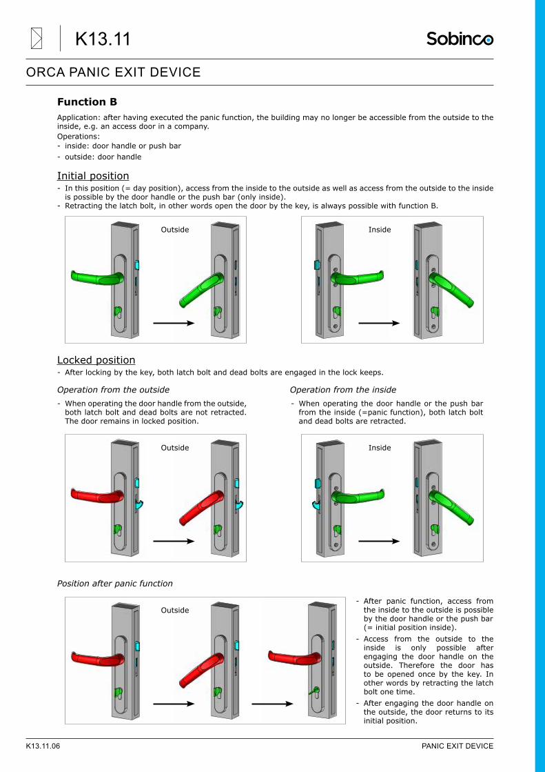
Function BApplication: after having executed the panic function, the building may no longer be accessible from the outside to the inside, e.g. an access door in a company.Operations: - inside: door handle or push bar - outside: door handle
Initial position - In this position (= day position), access from the inside to the outside as well as access from the outside to the inside is possible by the door handle or the push bar (only inside).
- Retracting the latch bolt, in other words open the door by the key, is always possible with function B.
Locked position - After locking by the key, both latch bolt and dead bolts are engaged in the lock keeps.
Operation from the outside Operation from the inside
Position after panic function
- After panic function, access from the inside to the outside is possible by the door handle or the push bar (= initial position inside).
- Access from the outside to the inside is only possible after engaging the door handle on the outside. Therefore the door has to be opened once by the key. In other words by retracting the latch bolt one time.
- After engaging the door handle on the outside, the door returns to its initial position.
Outside Inside
- When operating the door handle from the outside, both latch bolt and dead bolts are not retracted. The door remains in locked position.
Outside
- When operating the door handle or the push bar from the inside (=panic function), both latch bolt and dead bolts are retracted.
Inside
Outside
K13.11.06 PANIC EXIT DEVICE
ORCA PANIC EXIT DEVICE
K13.11
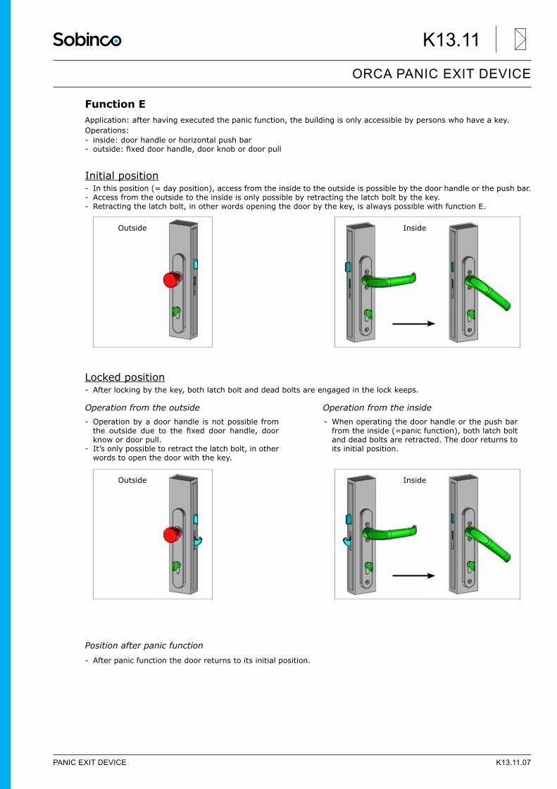
Function EApplication: after having executed the panic function, the building is only accessible by persons who have a key.Operations: - inside: door handle or horizontal push bar - outside:fixeddoorhandle,doorknobordoorpull
Initial position - In this position (= day position), access from the inside to the outside is possible by the door handle or the push bar. - Access from the outside to the inside is only possible by retracting the latch bolt by the key. - Retracting the latch bolt, in other words opening the door by the key, is always possible with function E.
Locked position - After locking by the key, both latch bolt and dead bolts are engaged in the lock keeps.
Operation from the outside Operation from the inside
Position after panic function
- After panic function the door returns to its initial position.
Outside Inside
- Operation by a door handle is not possible from the outside due to the fixed door handle, doorknow or door pull.
- It’s only possible to retract the latch bolt, in other words to open the door with the key.
Outside
- When operating the door handle or the push bar from the inside (=panic function), both latch bolt and dead bolts are retracted. The door returns to its initial position.
Inside
PANIC EXIT DEVICE K13.11.07
ORCA PANIC EXIT DEVICE
K13.11
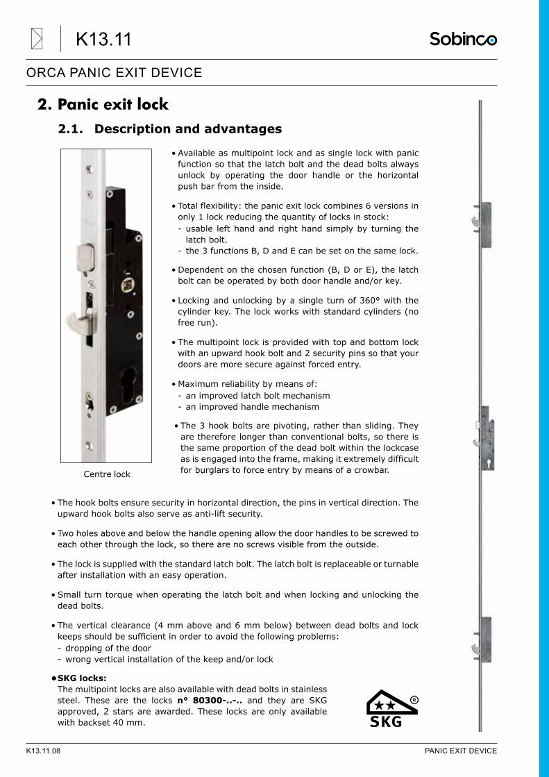
2. Panic exit lock2.1. Description and advantages
• Available as multipoint lock and as single lock with panic function so that the latch bolt and the dead bolts always unlock by operating the door handle or the horizontal push bar from the inside.
• Totalflexibility:thepanicexitlockcombines6versionsinonly 1 lock reducing the quantity of locks in stock: - usable left hand and right hand simply by turning the latch bolt.
- the 3 functions B, D and E can be set on the same lock.
• Dependent on the chosen function (B, D or E), the latch bolt can be operated by both door handle and/or key.
• Locking and unlocking by a single turn of 360° with the cylinder key. The lock works with standard cylinders (no free run).
• The multipoint lock is provided with top and bottom lock with an upward hook bolt and 2 security pins so that your doors are more secure against forced entry.
• Maximum reliability by means of: - an improved latch bolt mechanism - an improved handle mechanism
• The 3 hook bolts are pivoting, rather than sliding. They are therefore longer than conventional bolts, so there is the same proportion of the dead bolt within the lockcase asisengagedintotheframe,makingitextremelydifficultfor burglars to force entry by means of a crowbar.
• The hook bolts ensure security in horizontal direction, the pins in vertical direction. The upward hook bolts also serve as anti-lift security.
• Two holes above and below the handle opening allow the door handles to be screwed to each other through the lock, so there are no screws visible from the outside.
• The lock is supplied with the standard latch bolt. The latch bolt is replaceable or turnable after installation with an easy operation.
• Small turn torque when operating the latch bolt and when locking and unlocking the dead bolts.
• The vertical clearance (4 mm above and 6 mm below) between dead bolts and lock keepsshouldbesufficientinordertoavoidthefollowingproblems: - dropping of the door - wrong vertical installation of the keep and/or lock
• SKG locks: The multipoint locks are also available with dead bolts in stainless steel. These are the locks n° 80300-..-.. and they are SKG approved, 2 stars are awarded. These locks are only available with backset 40 mm.
Centre lock
K13.11.08 PANIC EXIT DEVICE
ORCA PANIC EXIT DEVICE
K13.11
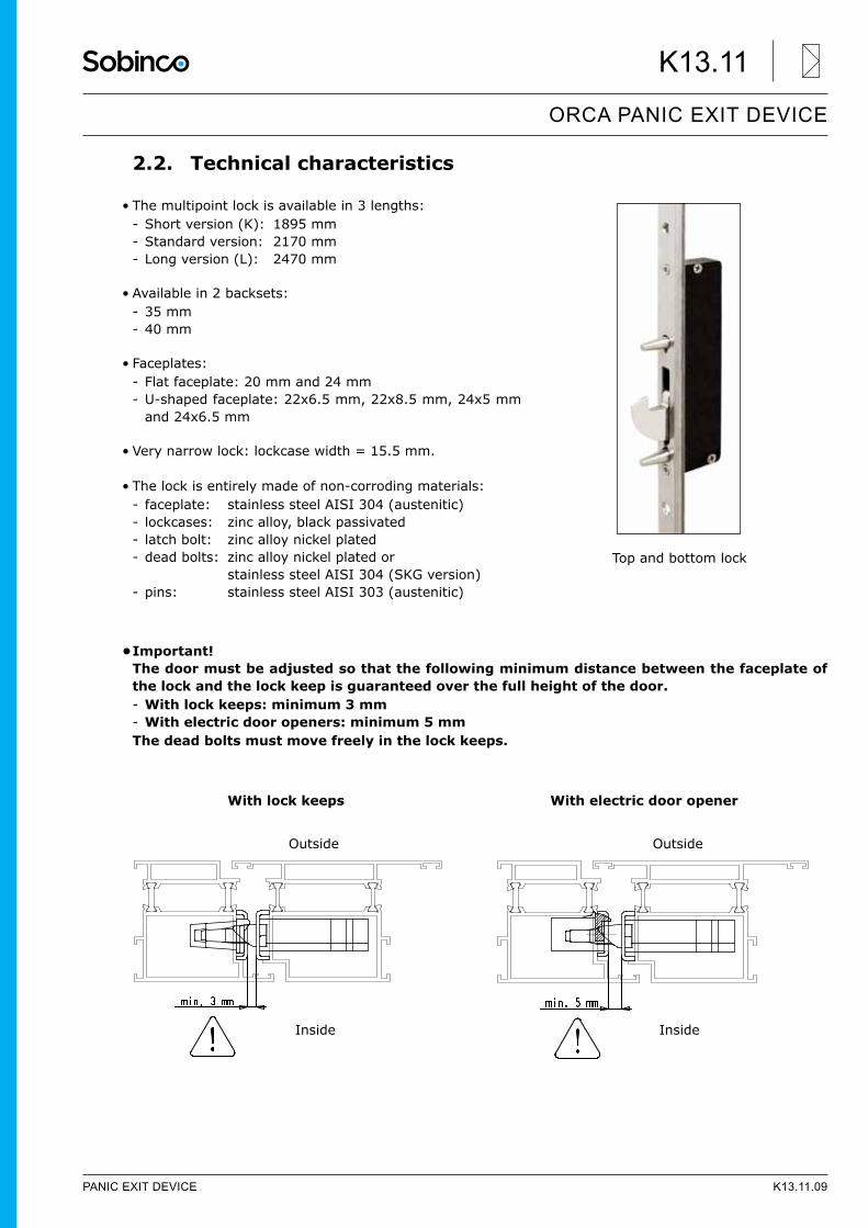
2.2. Technical characteristics
• The multipoint lock is available in 3 lengths: - Short version (K): 1895 mm - Standard version: 2170 mm - Long version (L): 2470 mm
• Available in 2 backsets: - 35 mm - 40 mm
• Faceplates: - Flat faceplate: 20 mm and 24 mm - U-shaped faceplate: 22x6.5 mm, 22x8.5 mm, 24x5 mm and 24x6.5 mm
• Very narrow lock: lockcase width = 15.5 mm.
• The lock is entirely made of non-corroding materials: - faceplate: stainless steel AISI 304 (austenitic) - lockcases: zinc alloy, black passivated - latch bolt: zinc alloy nickel plated - dead bolts: zinc alloy nickel plated or stainless steel AISI 304 (SKG version)
- pins: stainless steel AISI 303 (austenitic)
• Important! The door must be adjusted so that the following minimum distance between the faceplate of the lock and the lock keep is guaranteed over the full height of the door. - With lock keeps: minimum 3 mm - With electric door openers: minimum 5 mm
The dead bolts must move freely in the lock keeps.
With lock keeps With electric door opener
Top and bottom lock
Outside
Inside
Outside
Inside
PANIC EXIT DEVICE K13.11.09
ORCA PANIC EXIT DEVICE
K13.11
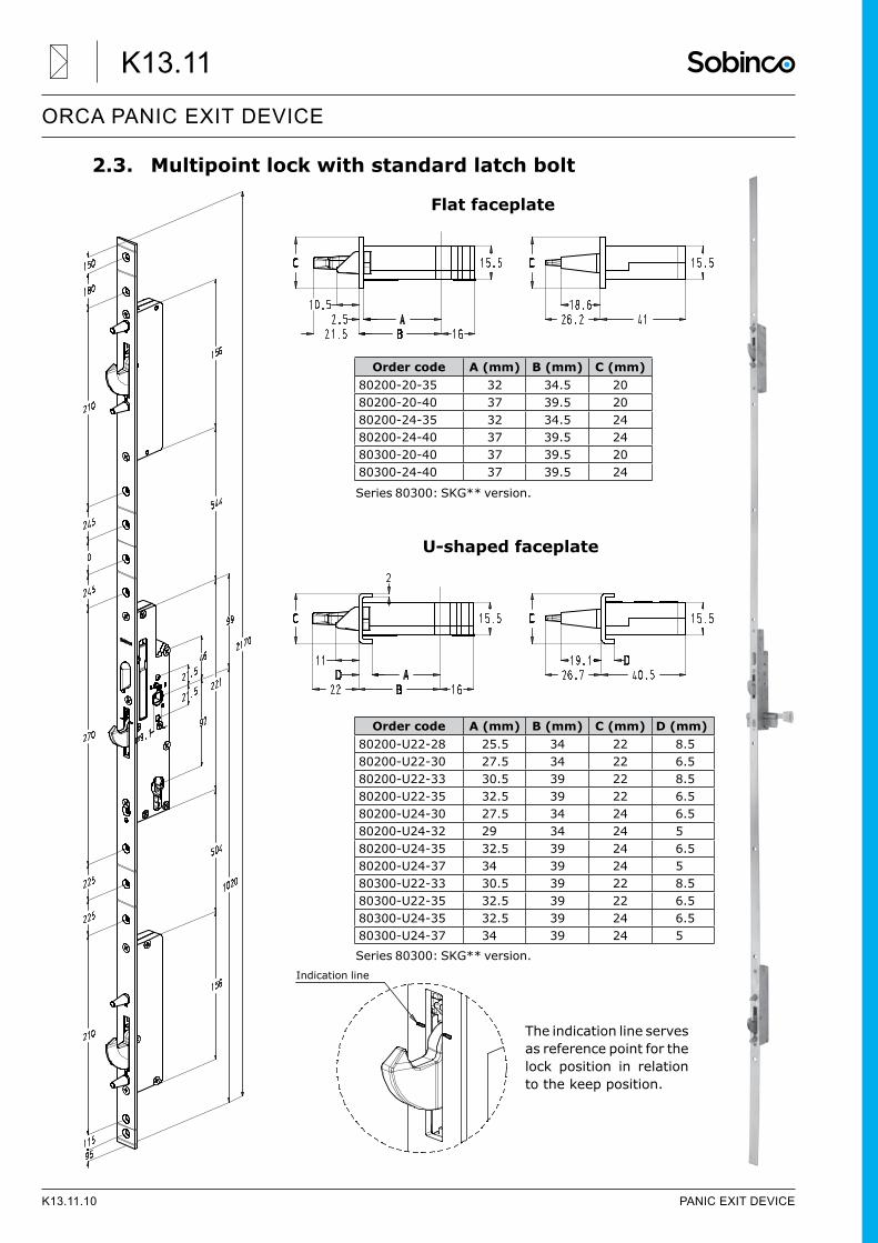
2.3. Multipoint lock with standard latch bolt
Flat faceplate
U-shaped faceplate
Series 80300: SKG** version.
Order code A (mm) B (mm) C (mm)80200-20-35 32 34.5 2080200-20-40 37 39.5 2080200-24-35 32 34.5 2480200-24-40 37 39.5 2480300-20-40 37 39.5 2080300-24-40 37 39.5 24
Series 80300: SKG** version.
Order code A (mm) B (mm) C (mm) D (mm)80200-U22-28 25.5 34 22 8.580200-U22-30 27.5 34 22 6.580200-U22-33 30.5 39 22 8.580200-U22-35 32.5 39 22 6.580200-U24-30 27.5 34 24 6.580200-U24-32 29 34 24 580200-U24-35 32.5 39 24 6.580200-U24-37 34 39 24 580300-U22-33 30.5 39 22 8.580300-U22-35 32.5 39 22 6.580300-U24-35 32.5 39 24 6.580300-U24-37 34 39 24 5
Indication line
The indication line serves as reference point for the lock position in relation to the keep position.
K13.11.10 PANIC EXIT DEVICE
ORCA PANIC EXIT DEVICE
K13.11
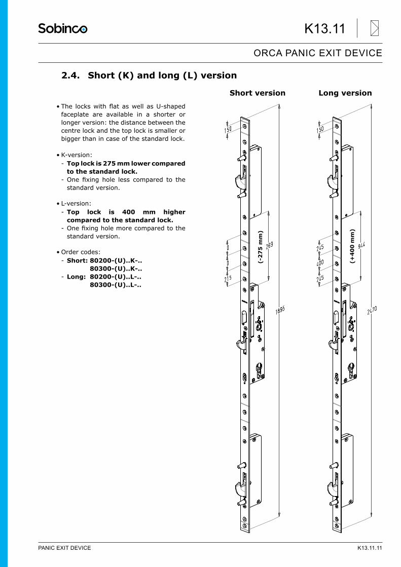
2.4. Short (K) and long (L) version
• The lockswithflataswellasU-shapedfaceplate are available in a shorter or longer version: the distance between the centre lock and the top lock is smaller or bigger than in case of the standard lock.
• K-version: - Top lock is 275 mm lower compared to the standard lock.
- One fixing hole less compared to thestandard version.
• L-version: - Top lock is 400 mm higher compared to the standard lock.
- Onefixingholemorecomparedtothestandard version.
• Order codes: - Short: 80200-(U)..K-.. 80300-(U)..K-..
- Long: 80200-(U)..L-.. 80300-(U)..L-..
Short version Long version
(-2
75
mm
)
(+4
00
mm
)
PANIC EXIT DEVICE K13.11.11
ORCA PANIC EXIT DEVICE
K13.11
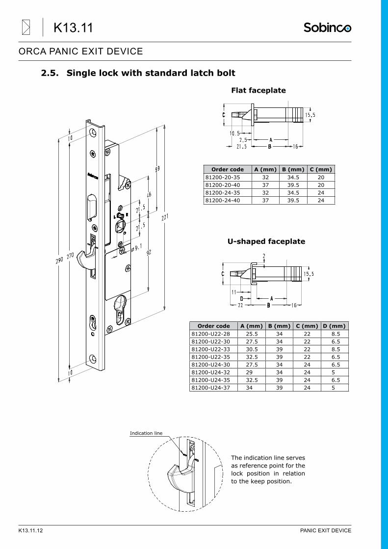
2.5. Single lock with standard latch bolt
Flat faceplate
U-shaped faceplate
Order code A (mm) B (mm) C (mm)81200-20-35 32 34.5 2081200-20-40 37 39.5 2081200-24-35 32 34.5 2481200-24-40 37 39.5 24
Indication line
The indication line serves as reference point for the lock position in relation to the keep position.
Order code A (mm) B (mm) C (mm) D (mm)81200-U22-28 25.5 34 22 8.581200-U22-30 27.5 34 22 6.581200-U22-33 30.5 39 22 8.581200-U22-35 32.5 39 22 6.581200-U24-30 27.5 34 24 6.581200-U24-32 29 34 24 581200-U24-35 32.5 39 24 6.581200-U24-37 34 39 24 5
K13.11.12 PANIC EXIT DEVICE
ORCA PANIC EXIT DEVICE
K13.11
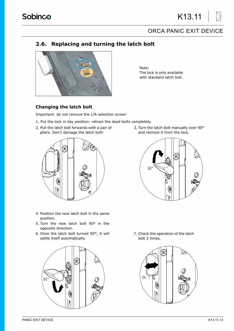
2.6. Replacing and turning the latch bolt
Changing the latch boltImportant: do not remove the L/R selection screw!
1. Put the lock in day position: retract the dead bolts completely.
L RNote: The lock is only available with standard latch bolt.
2. Pull the latch bolt forwards with a pair of pliers. Don’t damage the latch bolt!
3. Turn the latch bolt manually over 90° and remove it from the lock.
4. Position the new latch bolt in the same position.
5. Turn the new latch bolt 90° in the opposite direction.
6. Once the latch bolt turned 90°, it will settle itself automatically.
7. Check the operation of the latch bolt 3 times.
PANIC EXIT DEVICE K13.11.13
ORCA PANIC EXIT DEVICE
K13.11
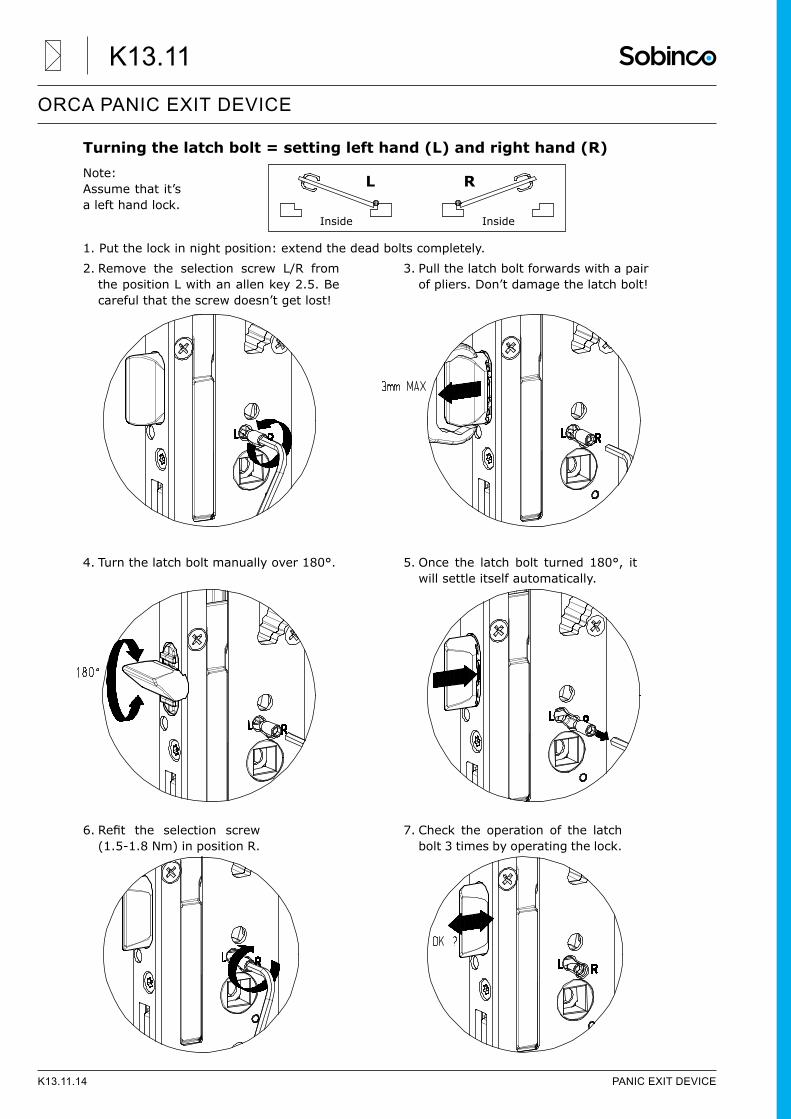
Turning the latch bolt = setting left hand (L) and right hand (R)Note: Assume that it’s a left hand lock.
1. Put the lock in night position: extend the dead bolts completely.
Inside
L
Inside
R
2. Remove the selection screw L/R from the position L with an allen key 2.5. Be careful that the screw doesn’t get lost!
3. Pull the latch bolt forwards with a pair of pliers. Don’t damage the latch bolt!
4. Turn the latch bolt manually over 180°. 5. Once the latch bolt turned 180°, it will settle itself automatically.
6.Refit the selection screw(1.5-1.8 Nm) in position R.
7. Check the operation of the latch bolt 3 times by operating the lock.
K13.11.14 PANIC EXIT DEVICE
ORCA PANIC EXIT DEVICE
K13.11
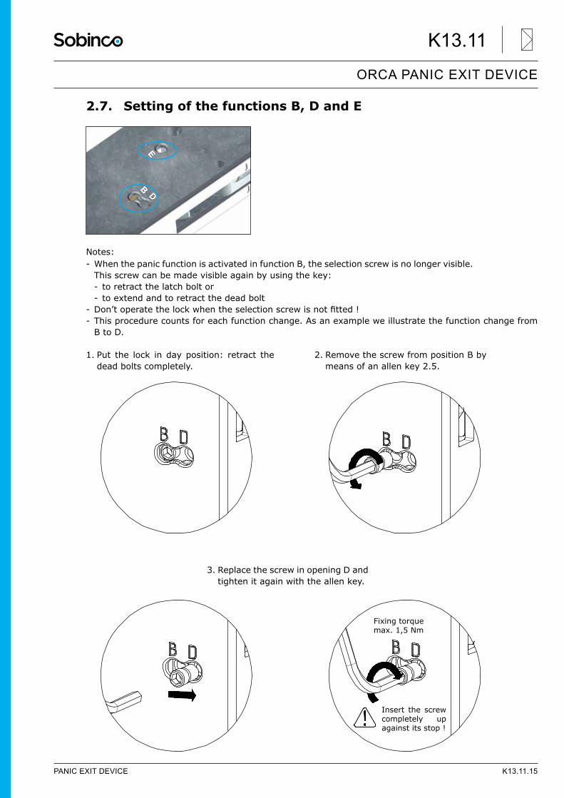
2.7. Setting of the functions B, D and E
Notes: - When the panic function is activated in function B, the selection screw is no longer visible. This screw can be made visible again by using the key: - to retract the latch bolt or - to extend and to retract the dead bolt
- Don’toperatethelockwhentheselectionscrewisnotfitted! - This procedure counts for each function change. As an example we illustrate the function change from B to D.
EB
D
1. Put the lock in day position: retract the dead bolts completely.
2. Remove the screw from position B by means of an allen key 2.5.
3. Replace the screw in opening D and tighten it again with the allen key.
Insert the screw completely up against its stop !
Fixing torquemax. 1,5 Nm
PANIC EXIT DEVICE K13.11.15
ORCA PANIC EXIT DEVICE
K13.11
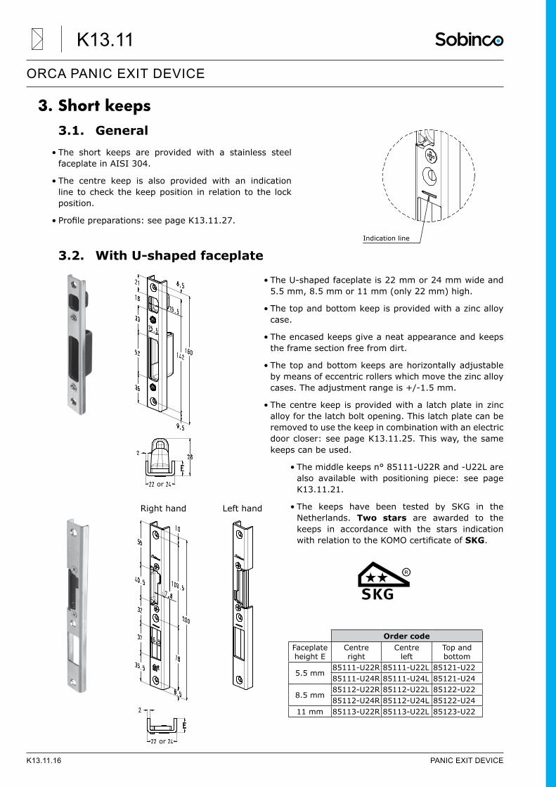
3. Short keeps3.1. General
• The short keeps are provided with a stainless steel faceplate in AISI 304.
• The centre keep is also provided with an indication line to check the keep position in relation to the lock position.
• Profilepreparations:seepageK13.11.27.
3.2. With U-shaped faceplate
• The U-shaped faceplate is 22 mm or 24 mm wide and 5.5 mm, 8.5 mm or 11 mm (only 22 mm) high.
• The top and bottom keep is provided with a zinc alloy case.
• The encased keeps give a neat appearance and keeps the frame section free from dirt.
• The top and bottom keeps are horizontally adjustable by means of eccentric rollers which move the zinc alloy cases. The adjustment range is +/-1.5 mm.
• The centre keep is provided with a latch plate in zinc alloy for the latch bolt opening. This latch plate can be removed to use the keep in combination with an electric door closer: see page K13.11.25. This way, the same keeps can be used.
• The middle keeps n° 85111-U22R and -U22L are also available with positioning piece: see page K13.11.21.
• The keeps have been tested by SKG in the Netherlands. Two stars are awarded to the keeps in accordance with the stars indication withrelationtotheKOMOcertificateofSKG.
Indication line
Order codeFaceplate height E
Centreright
Centreleft
Top andbottom
5.5 mm85111-U22R 85111-U22L 85121-U2285111-U24R 85111-U24L 85121-U24
8.5 mm85112-U22R 85112-U22L 85122-U2285112-U24R 85112-U24L 85122-U24
11 mm 85113-U22R 85113-U22L 85123-U22
Right hand Left hand
or
or
K13.11.16 PANIC EXIT DEVICE
ORCA PANIC EXIT DEVICE
K13.11
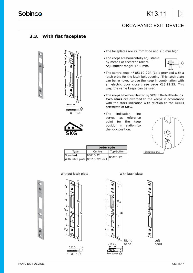
3.3. Withflatfaceplate
• The faceplates are 22 mm wide and 2.5 mm high.
• The keeps are horizontally adjustable by means of eccentric rollers. Adjustment range: +/-2 mm.
• The centre keep n° 85110-22R (L) is provided with a latch plate for the latch bolt opening. This latch plate can be removed to use the keep in combination with an electric door closer: see page K13.11.25. This way, the same keeps can be used.
• The keeps have been tested by SKG in the Netherlands. Two stars are awarded to the keeps in accordance with the stars indication with relation to the KOMO certificateofSKG.
• The indication line serves as reference point for the keep position in relation to the lock position.
Order codeType Centre Top/bottom
Standard 85010-2285020-22
With latch plate 85110-22R or L
Right hand
Left hand
With latch plateWithout latch plate
Indication line
PANIC EXIT DEVICE K13.11.17
ORCA PANIC EXIT DEVICE
K13.11
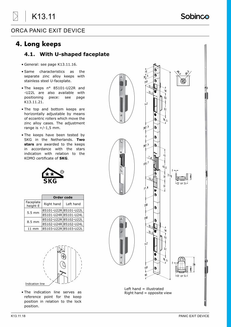
4. Long keeps4.1. With U-shaped faceplate
• General: see page K13.11.16.
• Same characteristics as the separate zinc alloy keeps with stainless steel U-faceplate.
• The keeps n° 85101-U22R and -U22L are also available with positioning piece: see page K13.11.21.
• The top and bottom keeps are horizontally adjustable by means of eccentric rollers which move the zinc alloy cases. The adjustment range is +/-1,5 mm.
• The keeps have been tested by SKG in the Netherlands. Two stars are awarded to the keeps in accordance with the stars indication with relation to the KOMOcertificateofSKG.
• The indication line serves as reference point for the keep position in relation to the lock position.
Left hand = illustratedRight hand = opposite view
or
or
Indication line
Order codeFaceplate height E Right hand Left hand
5.5 mm85101-U22R 85101-U22L85101-U24R 85101-U24L
8.5 mm85102-U22R 85102-U22L85102-U24R 85102-U24L
11 mm 85103-U22R 85103-U22L
K13.11.18 PANIC EXIT DEVICE
ORCA PANIC EXIT DEVICE
K13.11
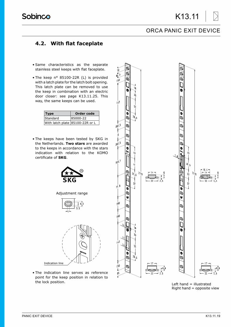
4.2. Withflatfaceplate
• Same characteristics as the separate stainlesssteelkeepswithflatfaceplate.
• The keep n° 85100-22R (L) is provided with a latch plate for the latch bolt opening. This latch plate can be removed to use the keep in combination with an electric door closer: see page K13.11.25. This way, the same keeps can be used.
• The keeps have been tested by SKG in the Netherlands. Two stars are awarded to the keeps in accordance with the stars indication with relation to the KOMO certificateofSKG.
• The indication line serves as reference point for the keep position in relation to the lock position. Left hand = illustrated
Right hand = opposite view
Type Order codeStandard 85000-22With latch plate 85100-22R or L
Indication line
Adjustment range
PANIC EXIT DEVICE K13.11.19
ORCA PANIC EXIT DEVICE
K13.11
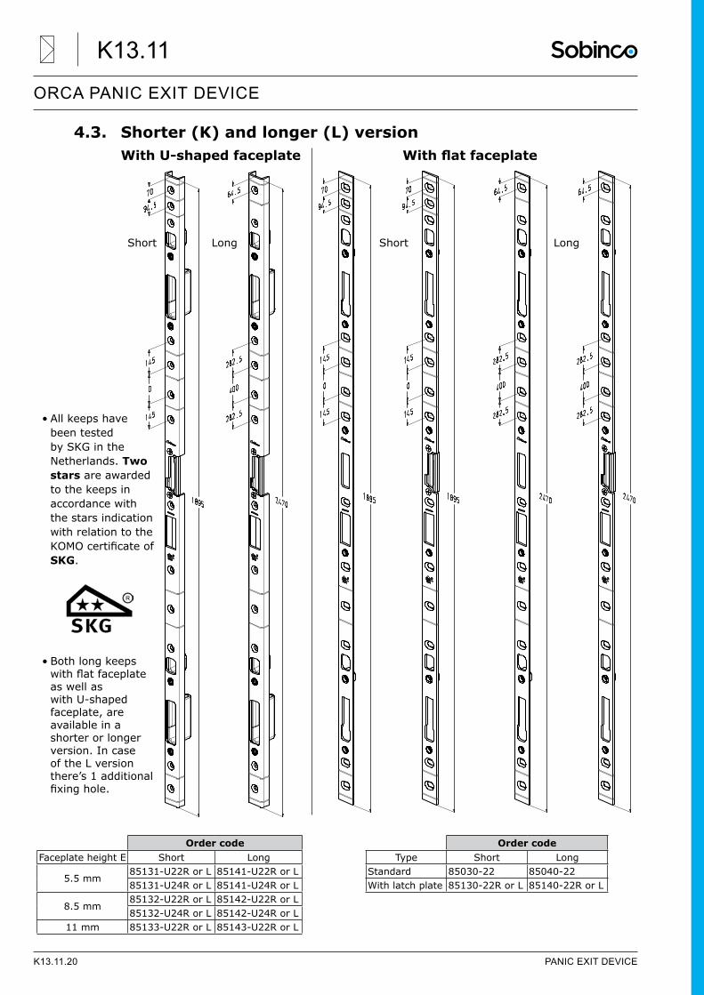
4.3. Shorter (K) and longer (L) versionWithU-shapedfaceplate Withflatfaceplate
• All keeps have been tested by SKG in the Netherlands. Two stars are awarded to the keeps in accordance with the stars indication with relation to the KOMOcertificateofSKG.
• Both long keeps withflatfaceplateas well as with U-shaped faceplate, are available in a shorter or longer version. In case of the L version there’s 1 additional fixinghole.
Order codeFaceplate height E Short Long
5.5 mm85131-U22R or L 85141-U22R or L85131-U24R or L 85141-U24R or L
8.5 mm85132-U22R or L 85142-U22R or L85132-U24R or L 85142-U24R or L
11 mm 85133-U22R or L 85143-U22R or L
Short Long
Order codeType Short Long
Standard 85030-22 85040-22With latch plate 85130-22R or L 85140-22R or L
Short Long
K13.11.20 PANIC EXIT DEVICE
ORCA PANIC EXIT DEVICE
K13.11
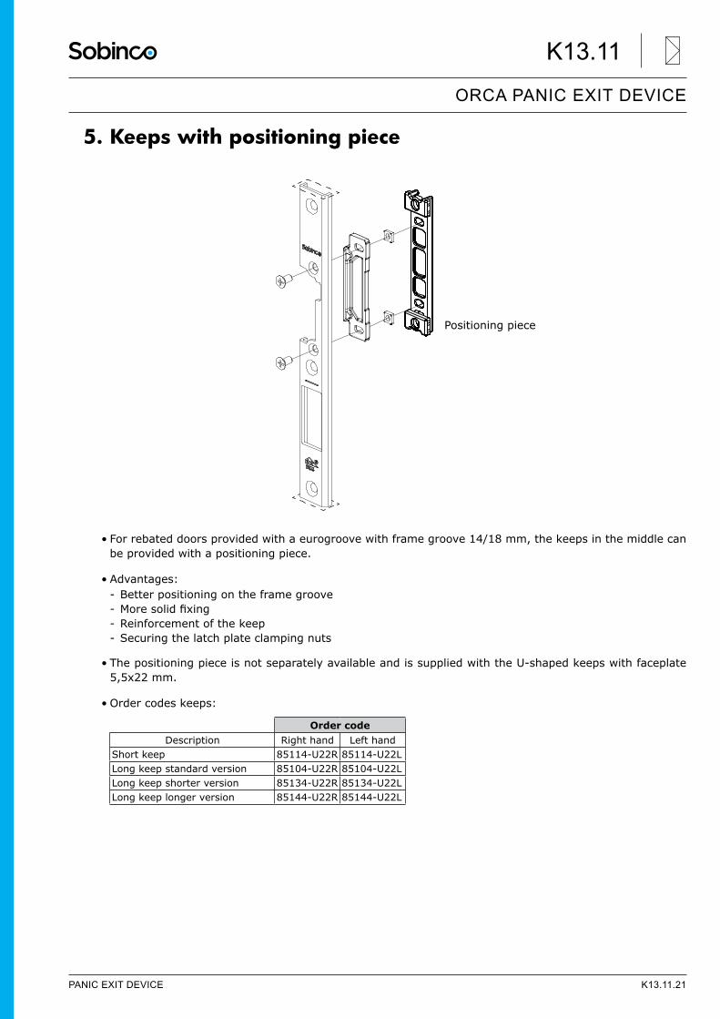
5. Keeps with positioning piece
• For rebated doors provided with a eurogroove with frame groove 14/18 mm, the keeps in the middle can be provided with a positioning piece.
• Advantages: - Better positioning on the frame groove - Moresolidfixing - Reinforcement of the keep - Securing the latch plate clamping nuts
• The positioning piece is not separately available and is supplied with the U-shaped keeps with faceplate 5,5x22 mm.
• Order codes keeps:
Positioning piece
Order codeDescription Right hand Left hand
Short keep 85114-U22R 85114-U22LLong keep standard version 85104-U22R 85104-U22LLong keep shorter version 85134-U22R 85134-U22LLong keep longer version 85144-U22R 85144-U22L
PANIC EXIT DEVICE K13.11.21
ORCA PANIC EXIT DEVICE
K13.11
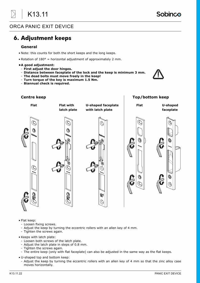
6. Adjustment keepsGeneral
• Note: this counts for both the short keeps and the long keeps.
• Rotation of 180° = horizontal adjustment of approximately 2 mm.
• A good adjustment: - First adjust the door hinges. - Distance between faceplate of the lock and the keep is minimum 3 mm. - The dead bolts must move freely in the keep! - Turn torque of the key is maximum 1.5 Nm. - Biannual check is required.
Centre keep Top/bottom keep
Flat Flat with U-shaped faceplate Flat U-shaped latch plate with latch plate faceplate
• Flat keep: - Loosenfixingscrews. - Adjust the keep by turning the eccentric rollers with an allen key of 4 mm. - Tighten the screws again.
• Keeps with latch plate: - Loosen both screws of the latch plate. - Adjust the latch plate in steps of 0.8 mm. - Tighten the screws again. - Theentirekeep(onlywithflatfaceplate)canalsobeadjustedinthesamewayastheflatkeeps.
• U-shaped top and bottom keep: - Adjust the keep by turning the eccentric rollers with an allen key of 4 mm so that the zinc alloy case moves horizontally.
K13.11.22 PANIC EXIT DEVICE
ORCA PANIC EXIT DEVICE
K13.11
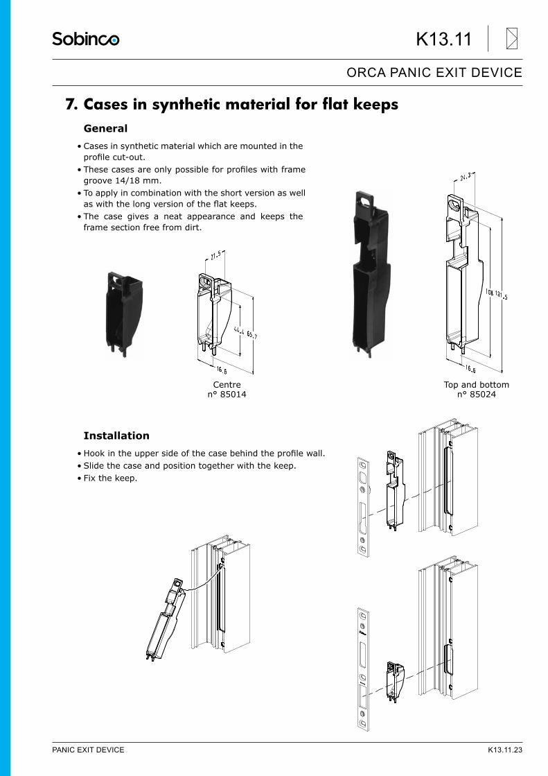
7. Cases in synthetic material for flat keepsGeneral
• Cases in synthetic material which are mounted in the profilecut-out.
• Thesecasesareonlypossibleforprofileswithframegroove 14/18 mm.
• To apply in combination with the short version as well aswiththelongversionoftheflatkeeps.
• The case gives a neat appearance and keeps the frame section free from dirt.
Installation• Hookintheuppersideofthecasebehindtheprofilewall.• Slide the case and position together with the keep.• Fix the keep.
Centren° 85014
Top and bottomn° 85024
PANIC EXIT DEVICE K13.11.23
ORCA PANIC EXIT DEVICE
K13.11
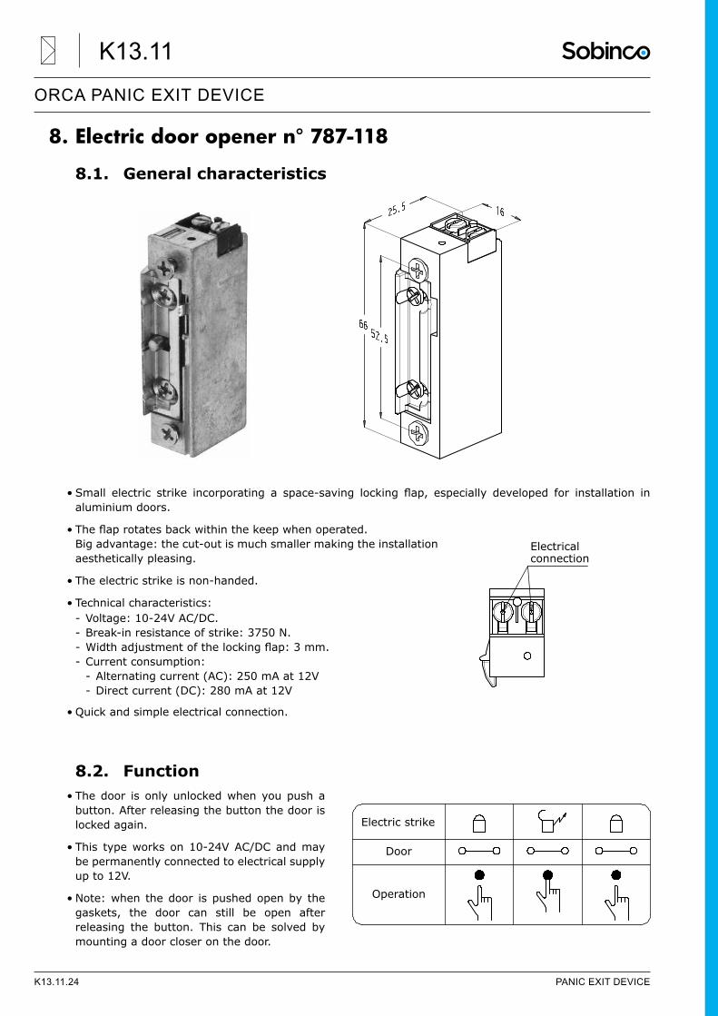
8. Electric door opener n° 787-118
8.1. General characteristics
• Small electric strike incorporating a space-saving locking flap, especially developed for installation inaluminium doors.
• Theflaprotatesbackwithinthekeepwhenoperated. Big advantage: the cut-out is much smaller making the installation aesthetically pleasing.
• The electric strike is non-handed.
• Technical characteristics: - Voltage: 10-24V AC/DC. - Break-in resistance of strike: 3750 N. - Widthadjustmentofthelockingflap:3mm. - Current consumption:
- Alternating current (AC): 250 mA at 12V - Direct current (DC): 280 mA at 12V
• Quick and simple electrical connection.
8.2. Function• The door is only unlocked when you push a
button. After releasing the button the door is locked again.
• This type works on 10-24V AC/DC and may be permanently connected to electrical supply up to 12V.
• Note: when the door is pushed open by the gaskets, the door can still be open after releasing the button. This can be solved by mounting a door closer on the door.
Electrical connection
Electric strike
Door
Operation
K13.11.24 PANIC EXIT DEVICE
ORCA PANIC EXIT DEVICE
K13.11
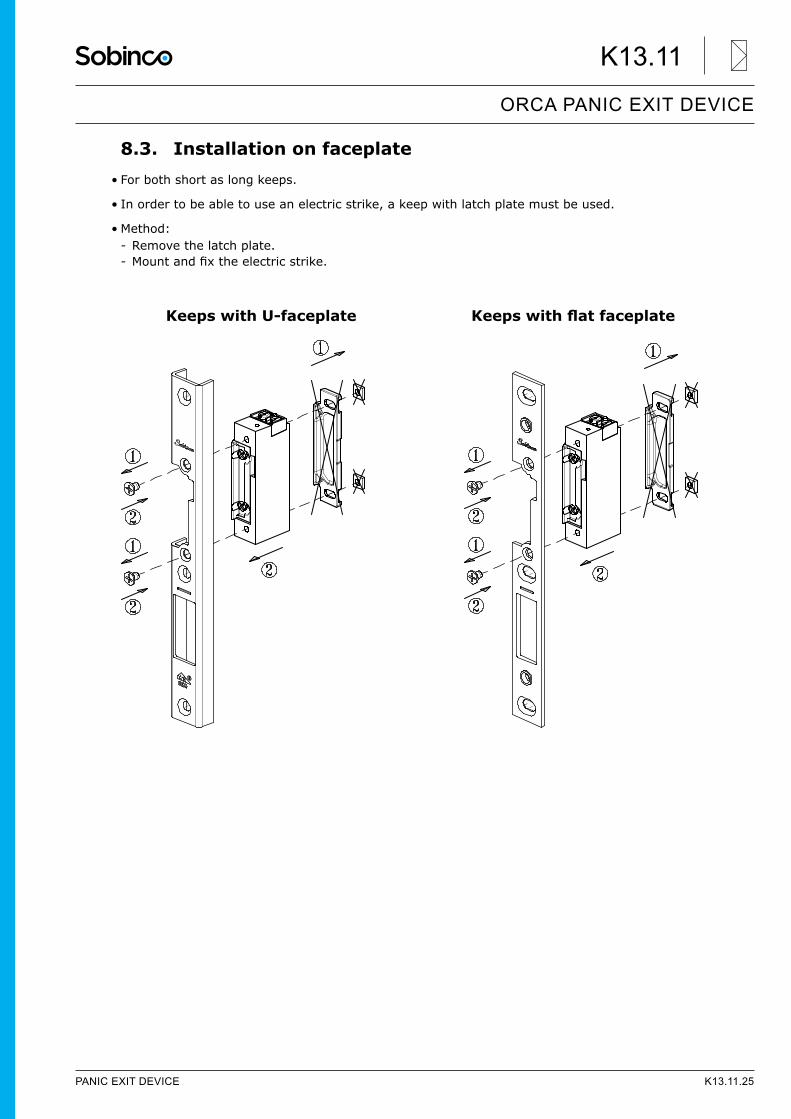
8.3. Installation on faceplate• For both short as long keeps.
• In order to be able to use an electric strike, a keep with latch plate must be used.
• Method: - Remove the latch plate. - Mountandfixtheelectricstrike.
KeepswithU-faceplate Keepswithflatfaceplate
PANIC EXIT DEVICE K13.11.25
ORCA PANIC EXIT DEVICE
K13.11
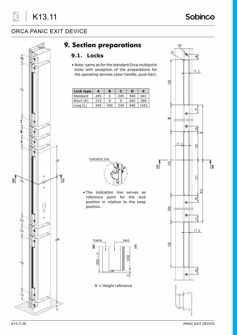
9. Section preparations9.1. Locks• Note: same as for the standard Orca multipoint
locks with exception of the preparations for the operating devices (door handle, push bar).
• The indication line serves as reference point for the lock position in relation to the keep position.
Lock type A B C D EStandard 245 0 245 540 641Short (K) 215 0 0 265 366Long (L) 245 400 245 940 1041
Indication line
R = Height reference
Frame Vent
K13.11.26 PANIC EXIT DEVICE
ORCA PANIC EXIT DEVICE
K13.11
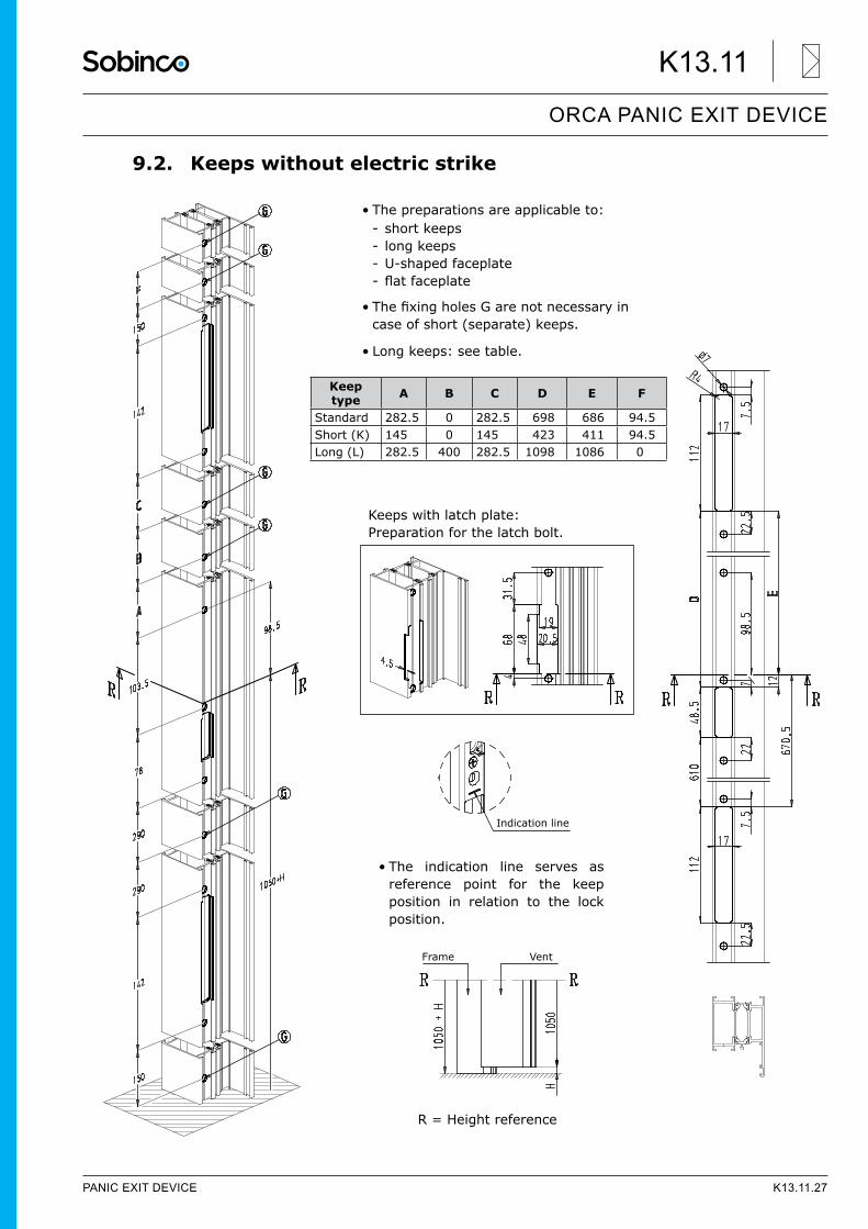
9.2. Keeps without electric strike
• The preparations are applicable to: - short keeps - long keeps - U-shaped faceplate - flatfaceplate
• ThefixingholesGarenotnecessaryincase of short (separate) keeps.
• Long keeps: see table.
• The indication line serves as reference point for the keep position in relation to the lock position.
Keep type A B C D E F
Standard 282.5 0 282.5 698 686 94.5Short (K) 145 0 145 423 411 94.5Long (L) 282.5 400 282.5 1098 1086 0
Indication line
R = Height reference
Frame Vent
Keeps with latch plate: Preparation for the latch bolt.
PANIC EXIT DEVICE K13.11.27
ORCA PANIC EXIT DEVICE
K13.11
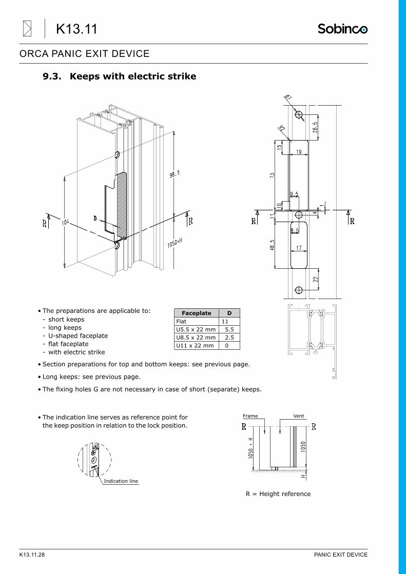
9.3. Keeps with electric strike
• The preparations are applicable to: - short keeps - long keeps - U-shaped faceplate - flatfaceplate - with electric strike
• Section preparations for top and bottom keeps: see previous page.
• Long keeps: see previous page.
• ThefixingholesGarenotnecessaryincaseofshort(separate)keeps.
• The indication line serves as reference point for the keep position in relation to the lock position.
Faceplate DFlat 11U5.5 x 22 mm 5.5U8.5 x 22 mm 2.5U11 x 22 mm 0
Indication line
R = Height reference
Frame Vent
K13.11.28 PANIC EXIT DEVICE
ORCA PANIC EXIT DEVICE
K13.11
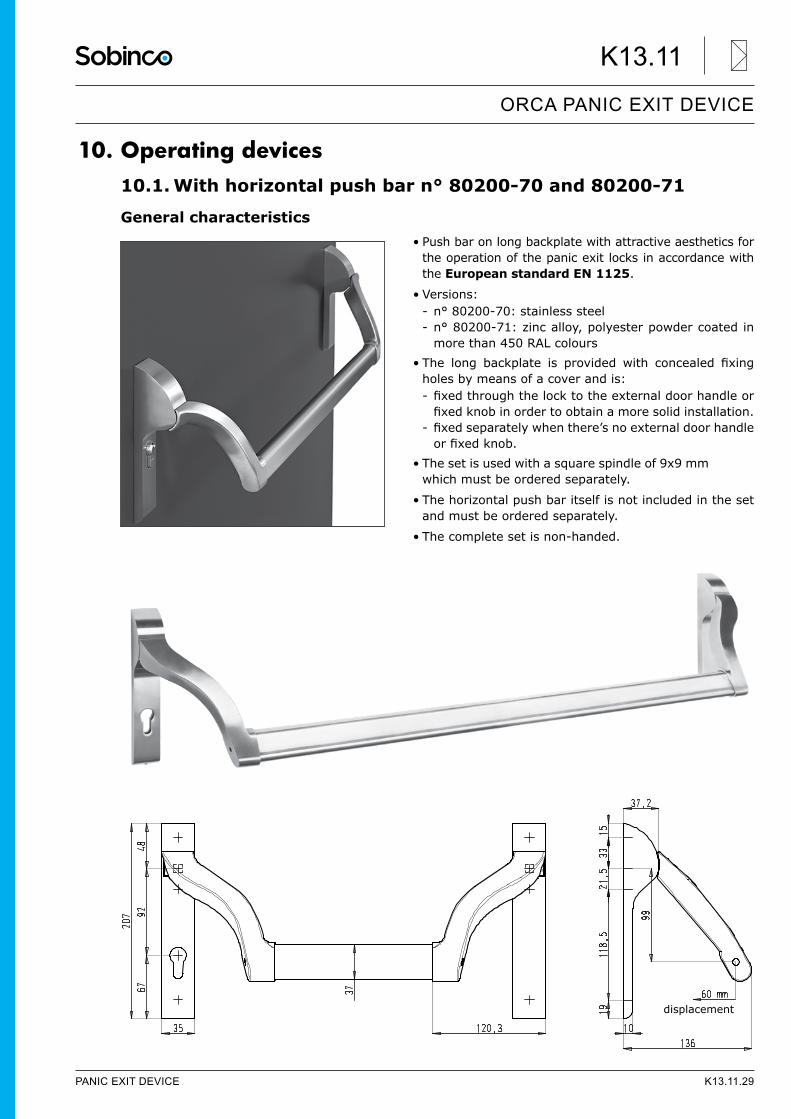
10. Operating devices10.1. With horizontal push bar n° 80200-70 and 80200-71
General characteristics• Push bar on long backplate with attractive aesthetics for
the operation of the panic exit locks in accordance with the European standard EN 1125.
• Versions: - n° 80200-70: stainless steel - n° 80200-71: zinc alloy, polyester powder coated in more than 450 RAL colours
• The long backplate is provided with concealed fixingholes by means of a cover and is: - fixedthroughthelocktotheexternaldoorhandleorfixedknobinordertoobtainamoresolidinstallation.
- fixedseparatelywhenthere’snoexternaldoorhandleorfixedknob.
• The set is used with a square spindle of 9x9 mm which must be ordered separately.
• The horizontal push bar itself is not included in the set and must be ordered separately.
• The complete set is non-handed.
displacement
PANIC EXIT DEVICE K13.11.29
ORCA PANIC EXIT DEVICE
K13.11
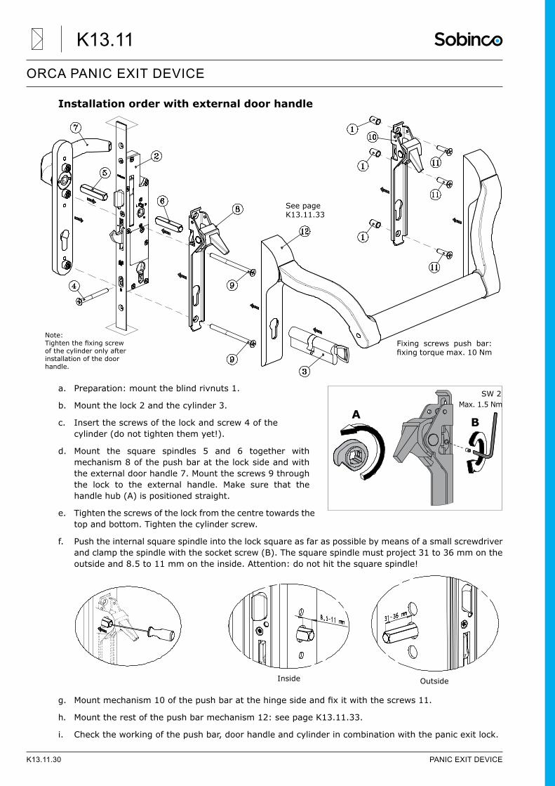
Installation order with external door handle
a. Preparation: mount the blind rivnuts 1.
b. Mount the lock 2 and the cylinder 3.
c. Insert the screws of the lock and screw 4 of the cylinder (do not tighten them yet!).
d. Mount the square spindles 5 and 6 together with mechanism 8 of the push bar at the lock side and with the external door handle 7. Mount the screws 9 through the lock to the external handle. Make sure that the handle hub (A) is positioned straight.
e. Tighten the screws of the lock from the centre towards the top and bottom. Tighten the cylinder screw.
f. Push the internal square spindle into the lock square as far as possible by means of a small screwdriver and clamp the spindle with the socket screw (B). The square spindle must project 31 to 36 mm on the outside and 8.5 to 11 mm on the inside. Attention: do not hit the square spindle!
g. Mountmechanism10ofthepushbaratthehingesideandfixitwiththescrews 11.
h. Mount the rest of the push bar mechanism 12: see page K13.11.33.
i. Check the working of the push bar, door handle and cylinder in combination with the panic exit lock.
See pageK13.11.33
Fixing screws push bar: fixingtorquemax.10Nm
Note:Tightenthefixingscrewof the cylinder only after installation of the door handle.
SW 2
AB
Max. 1.5 Nm
OutsideInside
K13.11.30 PANIC EXIT DEVICE
ORCA PANIC EXIT DEVICE
K13.11
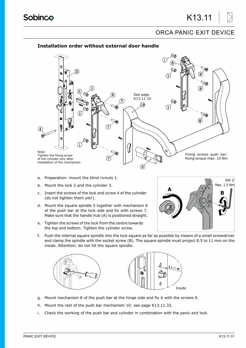
Installation order without external door handle
a. Preparation: mount the blind rivnuts 1.
b. Mount the lock 2 and the cylinder 3.
c. Insert the screws of the lock and screw 4 of the cylinder (do not tighten them yet!).
d. Mount the square spindle 5 together with mechanism 6 ofthepushbaratthelocksideandfixwithscrews7.Make sure that the handle hub (A) is positioned straight.
e. Tighten the screws of the lock from the centre towards the top and bottom. Tighten the cylinder screw.
f. Push the internal square spindle into the lock square as far as possible by means of a small screwdriver and clamp the spindle with the socket screw (B). The square spindle must project 8.5 to 11 mm on the inside. Attention: do not hit the square spindle.
g. Mountmechanism8ofthepushbaratthehingesideandfixitwiththescrews 9.
h. Mount the rest of the push bar mechanism 10: see page K13.11.33.
i. Check the working of the push bar and cylinder in combination with the panic exit lock.
See pageK13.11.33
Fixing screws push bar: fixingtorquemax.10Nm
Note:Tightenthefixingscrewof the cylinder only after installation of the mechanism
SW 2
AB
Max. 1.5 Nm
Inside
PANIC EXIT DEVICE K13.11.31
ORCA PANIC EXIT DEVICE
K13.11
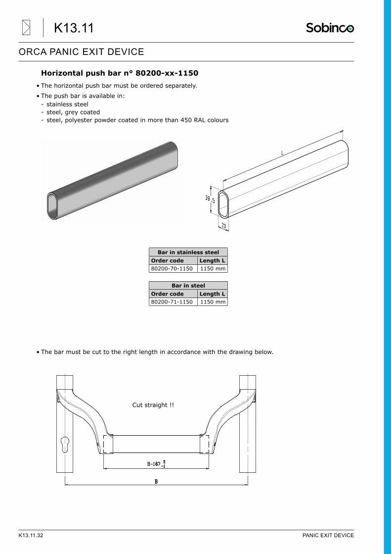
Horizontal push bar n° 80200-xx-1150• The horizontal push bar must be ordered separately.
• The push bar is available in: - stainless steel - steel, grey coated - steel, polyester powder coated in more than 450 RAL colours
• The bar must be cut to the right length in accordance with the drawing below.
Bar in steelOrder code Length L80200-71-1150 1150 mm
Bar in stainless steelOrder code Length L80200-70-1150 1150 mm
Cut straight !!
K13.11.32 PANIC EXIT DEVICE
ORCA PANIC EXIT DEVICE
K13.11
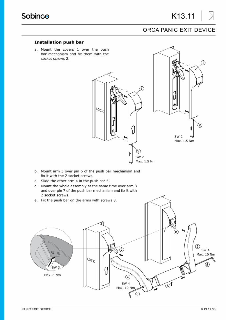
Installation push bara. Mount the covers 1 over the push
barmechanismandfix themwith thesocket screws 2.
b. Mount arm 3 over pin 6 of the push bar mechanism and fixitwiththe2socketscrews.
c. Slide the other arm 4 in the push bar 5.d. Mount the whole assembly at the same time over arm 3
andoverpin7ofthepushbarmechanismandfixitwith2 socket screws.
e. Fix the push bar on the arms with screws 8.
Max. 1.5 Nm
Max. 1.5 Nm
SW 2
SW 2
LOCK
SW 3
Max. 8 Nm
Max. 10 Nm
Max. 10 NmSW 4
SW 4
LOCK
PANIC EXIT DEVICE K13.11.33
ORCA PANIC EXIT DEVICE
K13.11
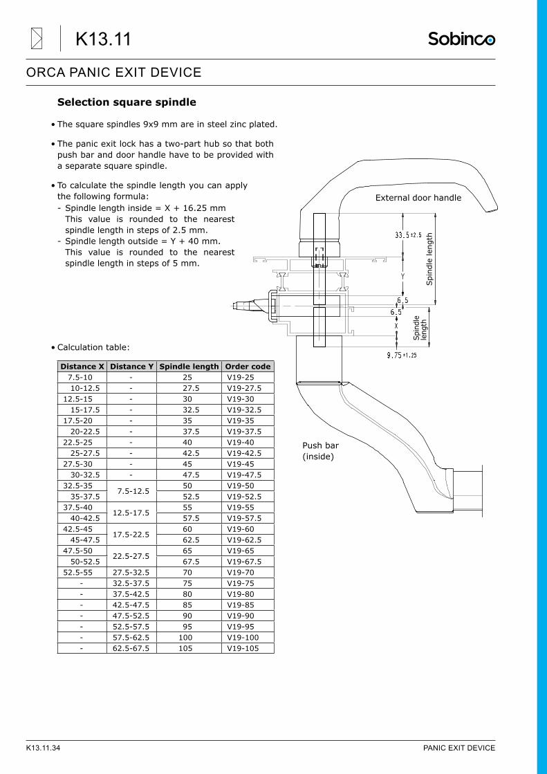
Selection square spindle
• The square spindles 9x9 mm are in steel zinc plated.
• The panic exit lock has a two-part hub so that both push bar and door handle have to be provided with a separate square spindle.
• To calculate the spindle length you can apply the following formula: - Spindle length inside = X + 16.25 mm This value is rounded to the nearest spindle length in steps of 2.5 mm.
- Spindle length outside = Y + 40 mm. This value is rounded to the nearest spindle length in steps of 5 mm.
• Calculation table:
External door handle
Spi
ndle
leng
th
Spin
dle
leng
th
Push bar(inside)
Distance X Distance Y Spindle length Order code7.5-10 - 25 V19-2510-12.5 - 27.5 V19-27.5
12.5-15 - 30 V19-3015-17.5 - 32.5 V19-32.5
17.5-20 - 35 V19-3520-22.5 - 37.5 V19-37.5
22.5-25 - 40 V19-4025-27.5 - 42.5 V19-42.5
27.5-30 - 45 V19-4530-32.5 - 47.5 V19-47.5
32.5-357.5-12.5
50 V19-5035-37.5 52.5 V19-52.5
37.5-4012.5-17.5
55 V19-5540-42.5 57.5 V19-57.5
42.5-4517.5-22.5
60 V19-6045-47.5 62.5 V19-62.5
47.5-5022.5-27.5
65 V19-6550-52.5 67.5 V19-67.5
52.5-55 27.5-32.5 70 V19-70- 32.5-37.5 75 V19-75- 37.5-42.5 80 V19-80- 42.5-47.5 85 V19-85- 47.5-52.5 90 V19-90- 52.5-57.5 95 V19-95- 57.5-62.5 100 V19-100- 62.5-67.5 105 V19-105
K13.11.34 PANIC EXIT DEVICE
ORCA PANIC EXIT DEVICE
K13.11
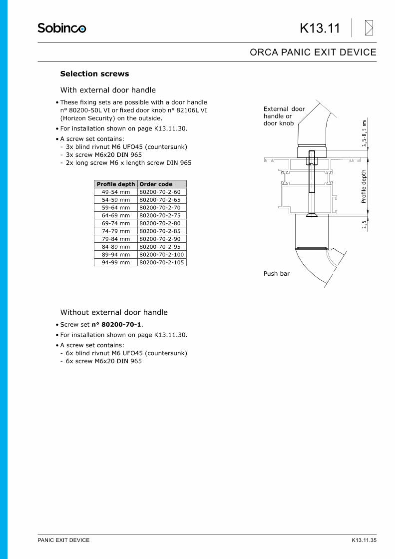
Selection screws
With external door handle• Thesefixingsetsarepossiblewithadoorhandlen°80200-50LVIorfixeddoorknobn°82106LVI(Horizon Security) on the outside.
• For installation shown on page K13.11.30.
• A screw set contains: - 3x blind rivnut M6 UFO45 (countersunk) - 3x screw M6x20 DIN 965 - 2x long screw M6 x length screw DIN 965
Without external door handle• Screw set n° 80200-70-1.
• For installation shown on page K13.11.30.
• A screw set contains: - 6x blind rivnut M6 UFO45 (countersunk) - 6x screw M6x20 DIN 965
Profiledepth
Push bar
External door handle ordoor knob
Profiledepth Order code49-54 mm 80200-70-2-6054-59 mm 80200-70-2-6559-64 mm 80200-70-2-7064-69 mm 80200-70-2-7569-74 mm 80200-70-2-8074-79 mm 80200-70-2-8579-84 mm 80200-70-2-9084-89 mm 80200-70-2-9589-94 mm 80200-70-2-10094-99 mm 80200-70-2-105
PANIC EXIT DEVICE K13.11.35
ORCA PANIC EXIT DEVICE
K13.11
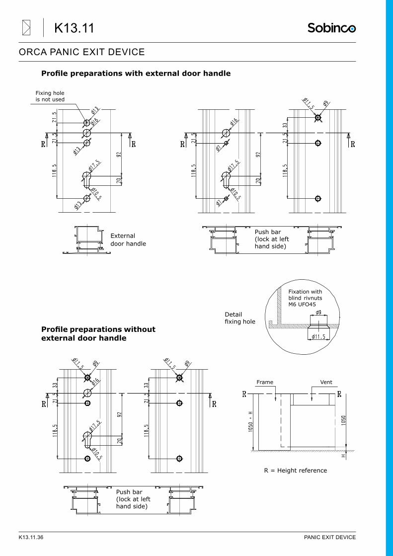
Profilepreparationswithexternaldoorhandle
Profilepreparationswithoutexternal door handle
Push bar(lock at lefthand side)
Fixing holeis not used
External door handle
Push bar(lock at lefthand side)
R = Height reference
Frame Vent
Fixation withblind rivnuts M6 UFO45
Detail fixinghole
K13.11.36 PANIC EXIT DEVICE
ORCA PANIC EXIT DEVICE
K13.11
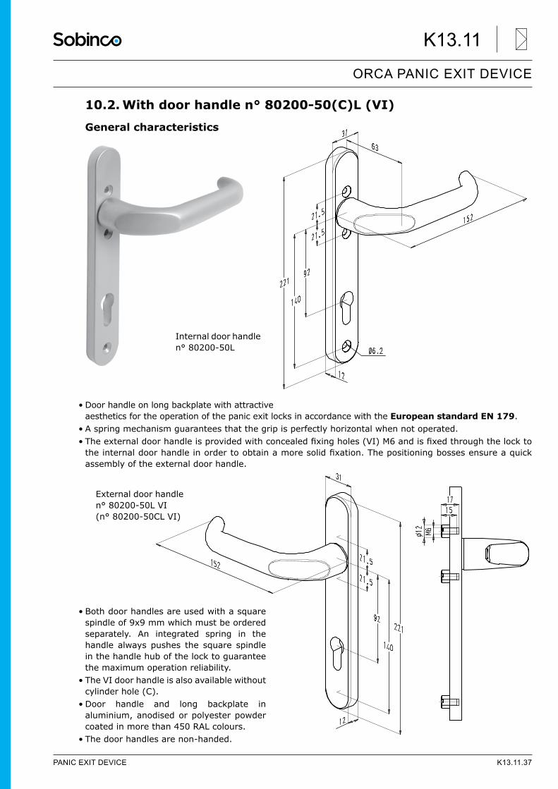
10.2. With door handle n° 80200-50(C)L (VI)
General characteristics
• Door handle on long backplate with attractive aesthetics for the operation of the panic exit locks in accordance with the European standard EN 179.
• A spring mechanism guarantees that the grip is perfectly horizontal when not operated.• Theexternaldoorhandleisprovidedwithconcealedfixingholes(VI)M6andisfixedthroughthelocktotheinternaldoorhandleinordertoobtainamoresolidfixation.Thepositioningbossesensureaquickassembly of the external door handle.
• Both door handles are used with a square spindle of 9x9 mm which must be ordered separately. An integrated spring in the handle always pushes the square spindle in the handle hub of the lock to guarantee the maximum operation reliability.
• The VI door handle is also available without cylinder hole (C).
• Door handle and long backplate in aluminium, anodised or polyester powder coated in more than 450 RAL colours.
• The door handles are non-handed.
Internal door handlen° 80200-50L
External door handlen° 80200-50L VI(n° 80200-50CL VI)
PANIC EXIT DEVICE K13.11.37
ORCA PANIC EXIT DEVICE
K13.11
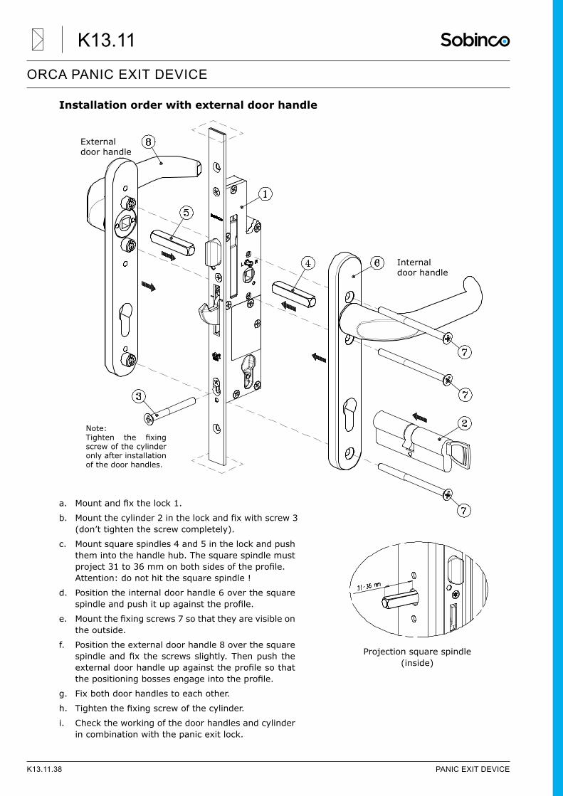
Installation order with external door handle
a. Mountandfixthelock1.
b. Mountthecylinder2inthelockandfixwithscrew3(don’t tighten the screw completely).
c. Mount square spindles 4 and 5 in the lock and push them into the handle hub. The square spindle must project31to36mmonbothsidesoftheprofile.Attention: do not hit the square spindle !
d. Position the internal door handle 6 over the square spindleandpushitupagainsttheprofile.
e. Mountthefixingscrews7sothattheyarevisibleonthe outside.
f. Position the external door handle 8 over the square spindleandfixthescrewsslightly.Thenpushtheexternaldoorhandleupagainsttheprofilesothatthepositioningbossesengageintotheprofile.
g. Fix both door handles to each other.
h. Tightenthefixingscrewofthecylinder.
i. Check the working of the door handles and cylinder in combination with the panic exit lock.
Internal door handle
External door handle
Note:Tighten the fixingscrew of the cylinder only after installation of the door handles.
Projection square spindle(inside)
K13.11.38 PANIC EXIT DEVICE
ORCA PANIC EXIT DEVICE
K13.11
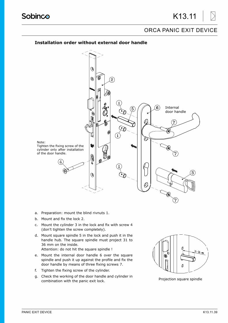
Installation order without external door handle
a. Preparation: mount the blind rivnuts 1.
b. Mountandfixthelock2.
c. Mountthecylinder3inthelockandfixwithscrew4(don’t tighten the screw completely).
d. Mount square spindle 5 in the lock and push it in the handle hub. The square spindle must project 31 to 36 mm on the inside. Attention: do not hit the square spindle !
e. Mount the internal door handle 6 over the square spindleandpushitupagainsttheprofileandfixthedoorhandlebymeansofthreefixingscrews7.
f. Tightenthefixingscrewofthecylinder.
g. Check the working of the door handle and cylinder in combination with the panic exit lock.
Note:Tightenthefixingscrewofthecylinder only after installation of the door handle.
Internal door handle
Projection square spindle
PANIC EXIT DEVICE K13.11.39
ORCA PANIC EXIT DEVICE
K13.11
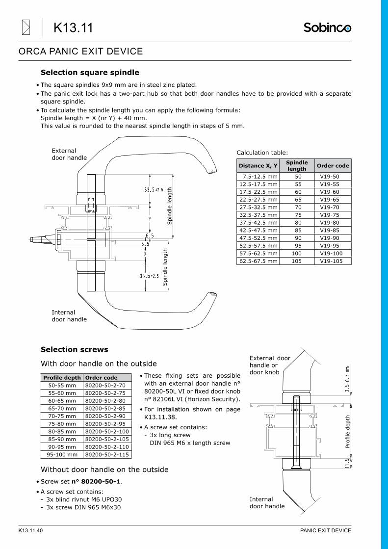
Selection square spindle• The square spindles 9x9 mm are in steel zinc plated.• The panic exit lock has a two-part hub so that both door handles have to be provided with a separate
square spindle.• To calculate the spindle length you can apply the following formula:
Spindle length = X (or Y) + 40 mm. This value is rounded to the nearest spindle length in steps of 5 mm.
Calculation table:
Selection screws
With door handle on the outside• These fixing sets are possible
with an external door handle n° 80200-50LVIorfixeddoorknobn° 82106L VI (Horizon Security).
• For installation shown on page K13.11.38.
• A screw set contains: - 3x long screw DIN 965 M6 x length screw
Without door handle on the outside• Screw set n° 80200-50-1.
• A screw set contains: - 3x blind rivnut M6 UPO30 - 3x screw DIN 965 M6x30
Spi
ndle
leng
thSpi
ndle
leng
th
Internal door handle
External door handle
Distance X, Y Spindle length Order code
7.5-12.5 mm 50 V19-5012.5-17.5 mm 55 V19-5517.5-22.5 mm 60 V19-6022.5-27.5 mm 65 V19-6527.5-32.5 mm 70 V19-7032.5-37.5 mm 75 V19-7537.5-42.5 mm 80 V19-8042.5-47.5 mm 85 V19-8547.5-52.5 mm 90 V19-9052.5-57.5 mm 95 V19-9557.5-62.5 mm 100 V19-10062.5-67.5 mm 105 V19-105
Profiledepth
Internal door handle
External door handle ordoor knob
Profiledepth Order code50-55 mm 80200-50-2-7055-60 mm 80200-50-2-7560-65 mm 80200-50-2-8065-70 mm 80200-50-2-8570-75 mm 80200-50-2-9075-80 mm 80200-50-2-9580-85 mm 80200-50-2-10085-90 mm 80200-50-2-10590-95 mm 80200-50-2-11095-100 mm 80200-50-2-115
K13.11.40 PANIC EXIT DEVICE
ORCA PANIC EXIT DEVICE
K13.11
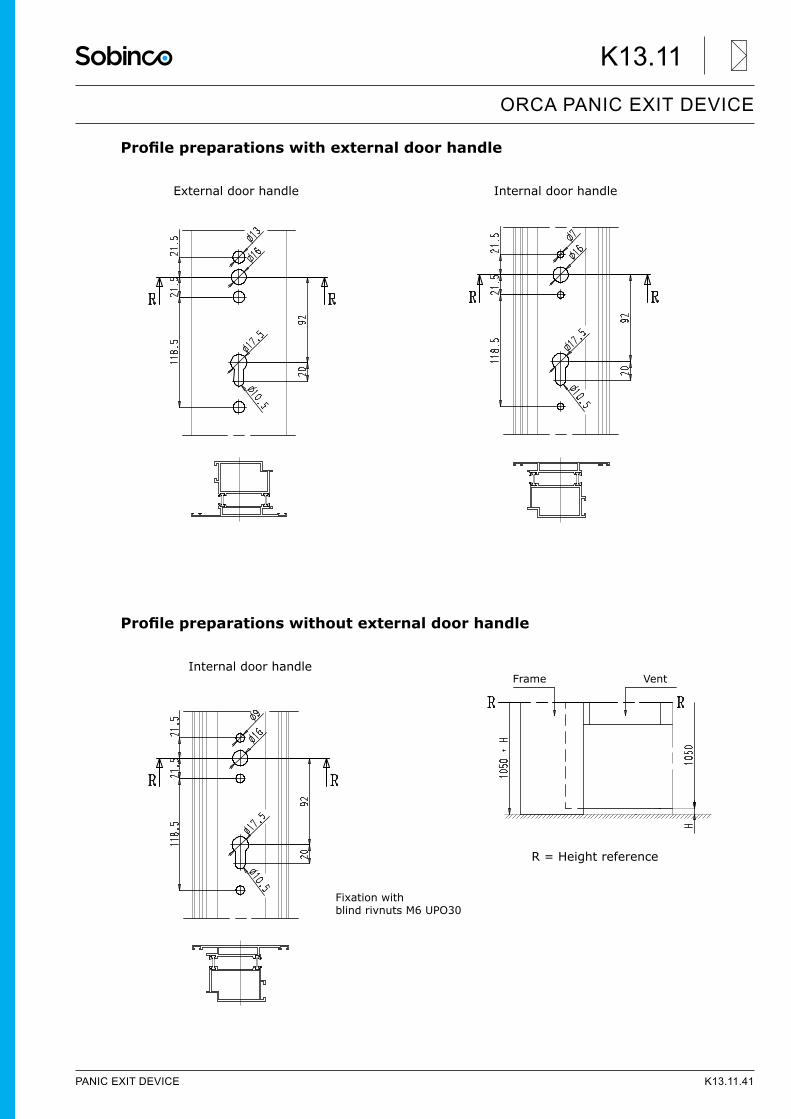
Profilepreparationswithexternaldoorhandle
External door handle Internal door handle
Profilepreparationswithoutexternaldoorhandle
Internal door handle
R = Height reference
Frame Vent
Fixation withblind rivnuts M6 UPO30
PANIC EXIT DEVICE K13.11.41
ORCA PANIC EXIT DEVICE
K13.11
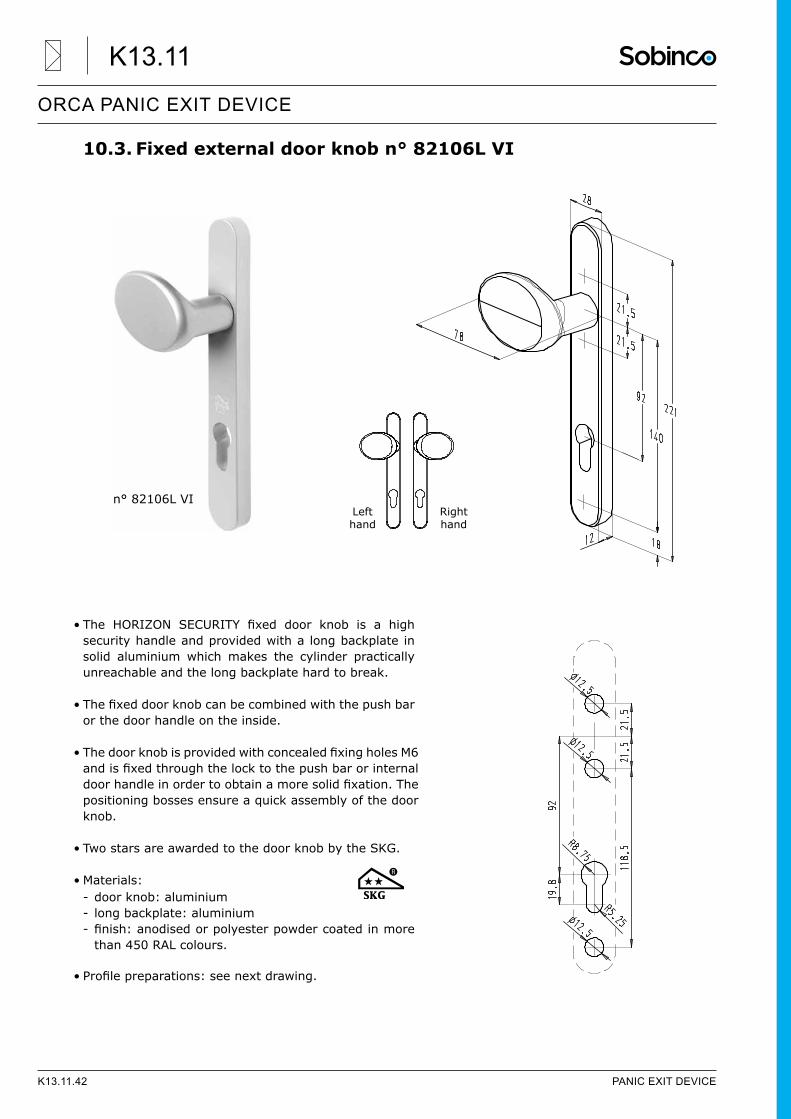
10.3. Fixed external door knob n° 82106L VI
• The HORIZON SECURITY fixed door knob is a highsecurity handle and provided with a long backplate in solid aluminium which makes the cylinder practically unreachable and the long backplate hard to break.
• Thefixeddoorknobcanbecombinedwiththepushbaror the door handle on the inside.
• ThedoorknobisprovidedwithconcealedfixingholesM6andisfixedthroughthelocktothepushbarorinternaldoorhandleinordertoobtainamoresolidfixation.Thepositioning bosses ensure a quick assembly of the door knob.
• Two stars are awarded to the door knob by the SKG.
• Materials: - door knob: aluminium - long backplate: aluminium - finish:anodisedorpolyesterpowdercoatedinmorethan 450 RAL colours.
• Profilepreparations:seenextdrawing.
n° 82106L VILeft hand
Right hand
K13.11.42 PANIC EXIT DEVICE
ORCA PANIC EXIT DEVICE
K13.11
11. General guidelines11.1. Coverage documentation
• This document is made for qualified door fabricators with the necessary experience and knowledgeregarding panic exit doors and emergency exits. All described operations have to be carried out by a qualifiedperson.Agoodperformancecanonlybeguaranteedwhentheworksaredoneinaccordancewiththedescribedinstructionsinthisdocument.Thereleaseofafinisheddoorafterinstallationonsiteisonlypossibleafterapprovalofanofficialinstaller.Theinstallationandmaintenanceinstructionsmustbehanded over by the door fabricator or installer to the end user after installation.
• In contrast with the standard door fittings, it’smandatory to use tested and approved operating devices incombination with the panic exit locks. Deviations are absolutely NOT allowed under any circumstance. This documentation contains the products which are related to panic exit doors in accordance with EN 179 and EN 1125.
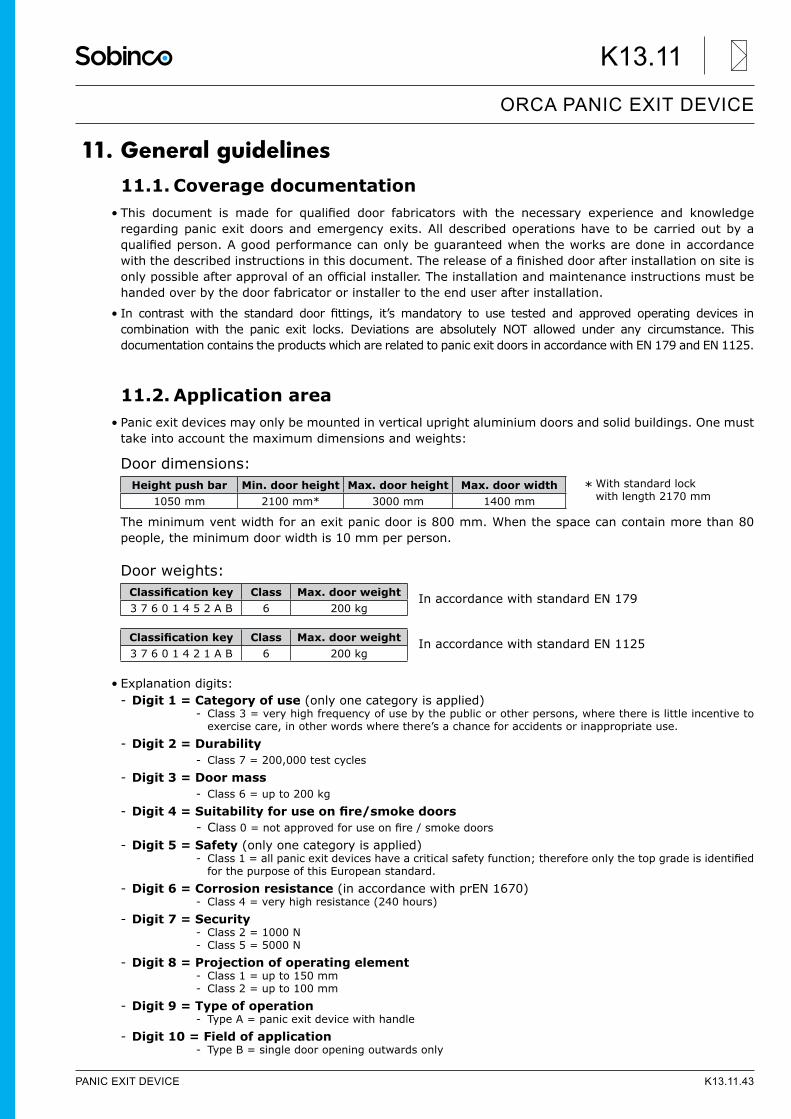
11.2. Application area• Panic exit devices may only be mounted in vertical upright aluminium doors and solid buildings. One must
take into account the maximum dimensions and weights:
Door dimensions:
The minimum vent width for an exit panic door is 800 mm. When the space can contain more than 80 people, the minimum door width is 10 mm per person.
Door weights:
In accordance with standard EN 179
In accordance with standard EN 1125
• Explanation digits: - Digit 1 = Category of use (only one category is applied)
- Class 3 = very high frequency of use by the public or other persons, where there is little incentive to exercise care, in other words where there’s a chance for accidents or inappropriate use.
- Digit 2 = Durability - Class 7 = 200,000 test cycles
- Digit 3 = Door mass - Class 6 = up to 200 kg
- Digit4=Suitabilityforuseonfire/smokedoors - Class0=notapprovedforuseonfire/smokedoors
- Digit 5 = Safety (only one category is applied) - Class1=allpanicexitdeviceshaveacriticalsafetyfunction;thereforeonlythetopgradeisidentifiedfor the purpose of this European standard.
- Digit 6 = Corrosion resistance (in accordance with prEN 1670) - Class 4 = very high resistance (240 hours)
- Digit 7 = Security - Class 2 = 1000 N - Class 5 = 5000 N
- Digit 8 = Projection of operating element - Class 1 = up to 150 mm - Class 2 = up to 100 mm
- Digit 9 = Type of operation - Type A = panic exit device with handle
- Digit 10 = Field of application - Type B = single door opening outwards only
* With standard lock with length 2170 mm
Height push bar Min. door height Max. door height Max. door width1050 mm 2100 mm* 3000 mm 1400 mm
Classificationkey Class Max. door weight3 7 6 0 1 4 5 2 A B 6 200 kg
Classificationkey Class Max. door weight3 7 6 0 1 4 2 1 A B 6 200 kg
PANIC EXIT DEVICE K13.11.43
ORCA PANIC EXIT DEVICE
K13.11
• The push bar must only be installed inside at a temperature from -10°C to +60°C. The door is preferably installed in an environment which is not continually subject to weather conditions.
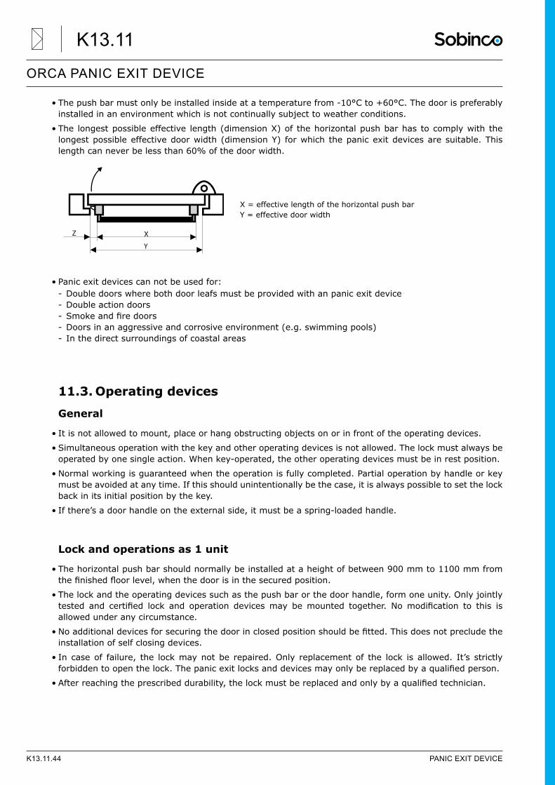
• The longest possible effective length (dimension X) of the horizontal push bar has to comply with the longest possible effective door width (dimension Y) for which the panic exit devices are suitable. This length can never be less than 60% of the door width.
• Panic exit devices can not be used for: - Double doors where both door leafs must be provided with an panic exit device - Double action doors - Smokeandfiredoors - Doors in an aggressive and corrosive environment (e.g. swimming pools) - In the direct surroundings of coastal areas
11.3. Operating devices
General
• It is not allowed to mount, place or hang obstructing objects on or in front of the operating devices.
• Simultaneous operation with the key and other operating devices is not allowed. The lock must always be operated by one single action. When key-operated, the other operating devices must be in rest position.
• Normal working is guaranteed when the operation is fully completed. Partial operation by handle or key must be avoided at any time. If this should unintentionally be the case, it is always possible to set the lock back in its initial position by the key.
• If there’s a door handle on the external side, it must be a spring-loaded handle.
Lock and operations as 1 unit
• The horizontal push bar should normally be installed at a height of between 900 mm to 1100 mm from thefinishedfloorlevel,whenthedoorisinthesecuredposition.
• The lock and the operating devices such as the push bar or the door handle, form one unity. Only jointly tested and certified lock and operation devicesmay bemounted together. Nomodification to this isallowed under any circumstance.
• Noadditionaldevicesforsecuringthedoorinclosedpositionshouldbefitted.Thisdoesnotprecludetheinstallation of self closing devices.
• In case of failure, the lock may not be repaired. Only replacement of the lock is allowed. It’s strictly forbiddentoopenthelock.Thepanicexitlocksanddevicesmayonlybereplacedbyaqualifiedperson.
• Afterreachingtheprescribeddurability,thelockmustbereplacedandonlybyaqualifiedtechnician.
Z X
Y
X = effective length of the horizontal push barY = effective door width
K13.11.44 PANIC EXIT DEVICE
ORCA PANIC EXIT DEVICE
K13.11
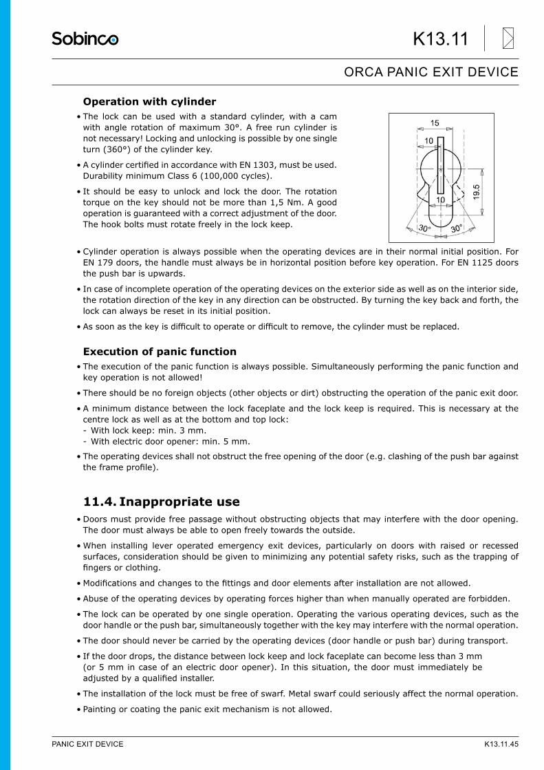
Operation with cylinder• The lock can be used with a standard cylinder, with a cam
with angle rotation of maximum 30°. A free run cylinder is not necessary! Locking and unlocking is possible by one single turn (360°) of the cylinder key.
• AcylindercertifiedinaccordancewithEN1303,mustbeused.Durability minimum Class 6 (100,000 cycles).
• It should be easy to unlock and lock the door. The rotation torque on the key should not be more than 1,5 Nm. A good operation is guaranteed with a correct adjustment of the door. The hook bolts must rotate freely in the lock keep.
• Cylinder operation is always possible when the operating devices are in their normal initial position. For EN 179 doors, the handle must always be in horizontal position before key operation. For EN 1125 doors the push bar is upwards.
• In case of incomplete operation of the operating devices on the exterior side as well as on the interior side, the rotation direction of the key in any direction can be obstructed. By turning the key back and forth, the lock can always be reset in its initial position.
• Assoonasthekeyisdifficulttooperateordifficulttoremove,thecylindermustbereplaced.
Execution of panic function• The execution of the panic function is always possible. Simultaneously performing the panic function and
key operation is not allowed!
• There should be no foreign objects (other objects or dirt) obstructing the operation of the panic exit door.
• A minimum distance between the lock faceplate and the lock keep is required. This is necessary at the centre lock as well as at the bottom and top lock: - With lock keep: min. 3 mm. - With electric door opener: min. 5 mm.
• The operating devices shall not obstruct the free opening of the door (e.g. clashing of the push bar against theframeprofile).
11.4. Inappropriate use• Doors must provide free passage without obstructing objects that may interfere with the door opening.
The door must always be able to open freely towards the outside.
• When installing lever operated emergency exit devices, particularly on doors with raised or recessed surfaces, consideration should be given to minimizing any potential safety risks, such as the trapping of fingersorclothing.
• Modificationsandchangestothefittingsanddoorelementsafterinstallationarenotallowed.
• Abuse of the operating devices by operating forces higher than when manually operated are forbidden.
• The lock can be operated by one single operation. Operating the various operating devices, such as the door handle or the push bar, simultaneously together with the key may interfere with the normal operation.
• The door should never be carried by the operating devices (door handle or push bar) during transport.
• If the door drops, the distance between lock keep and lock faceplate can become less than 3 mm (or 5 mm in case of an electric door opener). In this situation, the door must immediately be adjustedbyaqualifiedinstaller.
• The installation of the lock must be free of swarf. Metal swarf could seriously affect the normal operation.
• Painting or coating the panic exit mechanism is not allowed.
PANIC EXIT DEVICE K13.11.45
ORCA PANIC EXIT DEVICE
K13.11
11.5. General installation instructions• It is recommended to verify that the door construction allows the use of the panic exit device. Check that
the distance between the hinge axis and the extreme edge at the handle side, makes it still possible that the door can be opened without obstruction.
• The panic exit devices manufactured in accordance with this European standards will provide a high degree ofsafetyandreasonablesecuritytopersonsandobjects,providedthattheyarefittedtodoorsthatarein good condition. Deformation of the door element must be avoided or kept to a minimum. Therefore the door element must be manufactured from quality and solid materials. Also the glass (or panel) should be mountedinaccordancewiththestandardsandgeneralrulesofprofessionalskill.Beforefittingthepanicexit device to the door, the door should be checked to ensure correct hanging and free from binding.
• In case of damage to the door or door elements (e.g. hinges), the lock should not be mounted.
• Theprofilepreparationsmustbemadefreeofswarfwhenmountingthelock!
• Mechanical operations such as milling or drilling are not allowed on the door when the lock is already mounted, thus avoiding metal swarf or dust entering the lock. Under no circumstances it is permitted to drill through the lock!
• All instructions and operations, described in the installation manual, should be treated with the necessary caution and accuracy, taking into account the installation tolerances.
• Fittingsandcylindermustbemountedfreeoftorsionandwithsufficientclearance.Thecylindermustbemounted completely straight.
• The square spindle must be mounted manually, the use of hammers or similar is prohibited.
• When mounting the operating devices, the instructions must be followed very accurately as described in ‘Operating devices’ on page K13.11.29.
• Screwsandotherfixingdevicesmustbefittedwiththerequiredtensionandtorqueasspecifiedinthisdocumentation.Theblindrivnutsmustbefittedinaccordancewiththegeneralrulesofprofessionalskillsothatasolidfixingisguaranteed.
• Onlyusethesuppliedfixingmaterials,unlessotherwisestated.
• The horizontal push bar should normally be installed so as to provide the maximum effective length.
• Only lock keeps in accordance with EN 179 or EN 1125 should be used. They must be mounted in such way in order to ensure compliance with these European standards.
• The correct distance between faceplate and lock keep must be respected, as mentioned in the installation manual.
• The installation must guarantee that the hook bolts always move freely in the lock keeps without friction, evenwhen there’s a load on the door. They should be fitted to provide secure engagement. Correctadjustment is described in the manual. Care should be taken to ensure that no projection of the hook bolts, when in withdrawn position, can prevent the door swinging freely.
• When the panic exit device is manufactured in more than one size, it is important that the correct size is selected.
• If a door closing device is to be used to return the door to the closed position, care should be taken not to impairtheuseofthedoorwaybytheyoung,elderlyandinfirm.
• When panic exit devices are mounted to a glazed door, it is essential that the glazing is tempered or laminated glass.
• Care should be taken to ensure that the acoustic and the weathersealsfittedtotheentiredoorassembly,donotinhibit the correct operation of the panic exit devices.
• After installation everything must function in a correct way. When this is not the case, this may indicate errors in the installation.
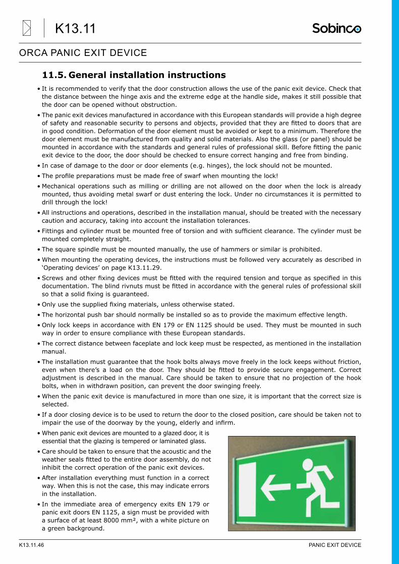
• In the immediate area of emergency exits EN 179 or panic exit doors EN 1125, a sign must be provided with a surface of at least 8000 mm², with a white picture on a green background.
K13.11.46 PANIC EXIT DEVICE
ORCA PANIC EXIT DEVICE
K13.11
11.6. Maintenance and checks
Inordertoguaranteeefficientproductoperation,asdescribedinthisdocument,thefollowingroutine maintenance checks are to be carried out at a regular time base:
• Routine maintenance: - Inspect the panic exit device very carefully and operate the push bar or door handle to ensure that all componentsareingoodconditionandstillworkefficiently.
- Check whether the lock, the keeps and operating devices are not obstructed by obstacles. The latch bolt and the dead bolts may not be blocked.
- The door has to be checked for easy opening and no deformation must be seen which can interfere with its good working.
- Cleaning of the door is only allowed with non-corrosive cleaning products.
• Maintenance every 6 months: - Operate the panic exit device using a force gauge and measure the operating force which is required toreleasethepanicexitlock.Checkthattherehasbeennosignificantchangeintheoperatingforcemeasured upon installation. In any case this release force should not exceed: - EN 1125: 80N in the horizontal direction over the full bar length, measured without counter-pressure. - EN 179: 70N in the vertical direction on the handle at 100 mm distance from the square spindle, measured without counter-pressure.
- Makesurethattheopeningmechanismisinefficientworkingconditions.Ifnecessary,adjustthelockingmechanisms as mentioned in the instruction manual to take up any clearance.
- Check whether the hook bolts can move freely in the lock keeps. - Measure the distance between faceplate and lock keep to check whether the door drops or not. - Inspectvisuallyandcheckthefixingsofthelockandlockkeepsverycarefully. - Checkthefixingsoftheoperatingdevices(doorhandleand/orpushbarmechanism). - If required, lubricate the matching points between dead bolts and lock keeps and the push bar mechanism with non-hardening lubricants.
- Checkthatall thesystemcomponentsarestill correctaccordingto the listofcertifiedcomponents,initially supplied with the system.
- Checkthatnoextrablockingdeviceshavebeenfittedonthedoorsinceitwasoriginallyassembled.
• Special instructions: - No guarantee in case of improper use or maintenance. - No additional lever systems or other tools should be used to operate the door. - Undernocircumstancesitispermittedtodrillthroughthelock,forexampletomakethefixingholesfor the door handles or the push bar. In general, swarf should not obstruct the working of the lock and the operating devices.
- The door handles and/or push bar should not be painted or coated afterwards because this can obstruct the mechanism.
- Thefinish(anodisingorpowdercoating)ofthedoorhandlesand/orthepushbarwillwithstanddailyuse if mounting and use are done properly. Excessive use with strange or hard items might scratch the surface and is beyond warranty even if the good working of the panic exit device is not affected in this case.
- Thecorrectmountingofthesecomponentsisofgreatimportanceforthesafetyofpeople.Nomodificationsof any kind are permitted, except for those described in these instructions.
PANIC EXIT DEVICE K13.11.47
ORCA PANIC EXIT DEVICE
K13.11
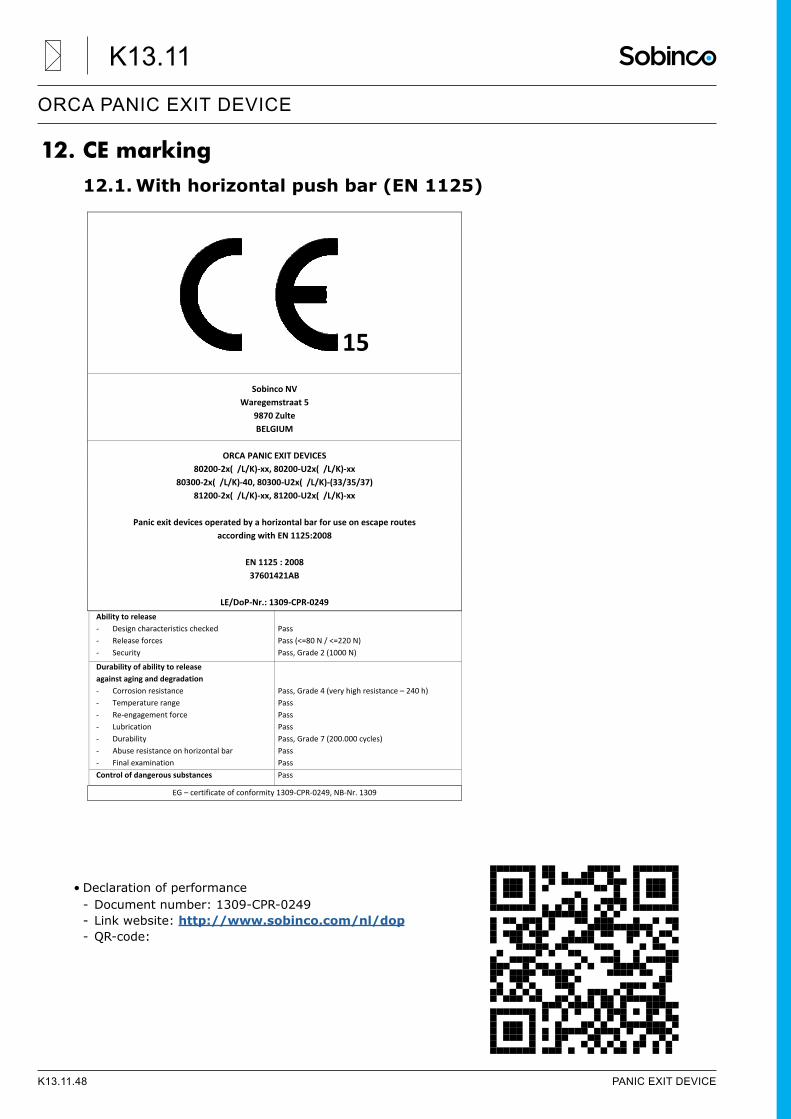
12. CE marking12.1. With horizontal push bar (EN 1125)
• Declaration of performance - Document number: 1309-CPR-0249 - Link website: http://www.sobinco.com/nl/dop - QR-code:
15
Sobinco NV Waregemstraat 5
9870 Zulte BELGIUM
ORCA PANIC EXIT DEVICES
80200‐2x( /L/K)‐xx, 80200‐U2x( /L/K)‐xx 80300‐2x( /L/K)‐40, 80300‐U2x( /L/K)‐(33/35/37)
81200‐2x( /L/K)‐xx, 81200‐U2x( /L/K)‐xx
Panic exit devices operated by a horizontal bar for use on escape routes according with EN 1125:2008
EN 1125 : 2008 37601421AB
LE/DoP‐Nr.: 1309‐CPR‐0249
Ability to release ‐ Design characteristics checked ‐ Release forces ‐ Security
Pass Pass (<=80 N / <=220 N) Pass, Grade 2 (1000 N)
Durability of ability to release against aging and degradation ‐ Corrosion resistance ‐ Temperature range ‐ Re‐engagement force ‐ Lubrication ‐ Durability ‐ Abuse resistance on horizontal bar ‐ Final examination
Pass, Grade 4 (very high resistance – 240 h) Pass Pass Pass Pass, Grade 7 (200.000 cycles) Pass Pass
Control of dangerous substances Pass
EG – certificate of conformity 1309‐CPR‐0249, NB‐Nr. 1309
K13.11.48 PANIC EXIT DEVICE
ORCA PANIC EXIT DEVICE
K13.11
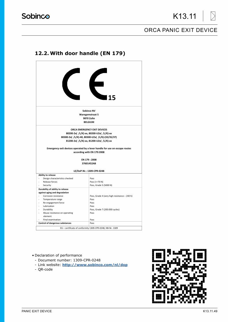
12.2. With door handle (EN 179)
• Declaration of performance - Document number: 1309-CPR-0248 - Link website: http://www.sobinco.com/nl/dop - QR-code
15
Sobinco NV Waregemstraat 5
9870 Zulte BELGIUM
ORCA EMERGENCY EXIT DEVICES
80200‐2x( /L/K)‐xx, 80200‐U2x( /L/K)‐xx 80300‐2x( /L/K)‐40, 80300‐U2x( /L/K)‐(33/35/37)
81200‐2x( /L/K)‐xx, 81200‐U2x( /L/K)‐xx
Emergency exit devices operated by a lever handle for use on escape routes according with EN 179:2008
EN 179 : 2008 37601452AB
LE/DoP‐Nr.: 1309‐CPR‐0248
Ability to release ‐ Design characteristics checked ‐ Release forces ‐ Security
Pass Pass (<=70 N) Pass, Grade 5 (5000 N)
Durability of ability to release against aging and degradation ‐ Corrosion resistance ‐ Temperature range ‐ Re‐engagement force ‐ Lubrication ‐ Durability ‐ Abuse resistance on operating
element ‐ Final examination
Pass, Grade 4 (very high resistance – 240 h) Pass Pass Pass Pass, Grade 7 (200.000 cycles) Pass Pass
Control of dangerous substances Pass
EG – certificate of conformity 1309‐CPR‐0248, NB‐Nr. 1309
PANIC EXIT DEVICE K13.11.49
ORCA PANIC EXIT DEVICE
K13.11