Embed Size (px)
Citation preview

Block PM307,Bertam Field Development Project
Review of PTI DocumentationDepartment of Occupational Safety & Health (DOSH)
Ministry of Human Resources
LMBV jointly submitted with
SUBSURF Sdn.Bhd/DOF SUBSEA
26 November 2014
TABLE OF CONTENT
1. Objective of Presentation
2. Bertam Field Background
3. Bertam Development Concept
4. General Arrangement
5. Project Schedule
6. PTI Documentation Requirement• DOSH Requirement vs Lundin’s Submission on 13 November 2014
7. Bertam Production Flow Plan/ Flow Path
8. Installation Procedure
9. QA/QC of Jumper Hoses and Accessories
1.0 OBJECTIVE OF PRESENTATION
To provide an overview of the project documentation submitted for
Bertam Field Development Project.
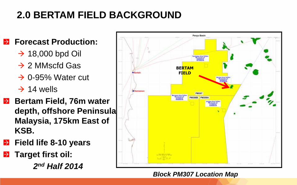
2.0 BERTAM FIELD BACKGROUND
Block PM307 Location Map
Forecast Production:
18,000 bpd Oil
2 MMscfd Gas
0-95% Water cut
14 wells
Bertam Field, 76m water
depth, offshore Peninsula
Malaysia, 175km East of
KSB.
Field life 8-10 years
Target first oil:
2nd Half 2014
BERTAM FIELD
2.0 BERTAM FIELD BACKGROUND
• Partnership: Lundin Malaysia B.V (75%, Operator) and Petronas Carigali (25%)
• Water Depth: ~76 m
• Production Sharing Contract (PSC) Effective: 15th August 1996
• PSC Expiry: 14th August 2025
• Lundin Farm-in: 1st May 2011
• Lundin as nominated Operator
• Lundin Owner of FPSO.
• Previous name ‘Ikdam’ when in Tunisia. New name FPSO Bertam.
• Field Development Plan Approved by Petronas & Partner Petronas Carigali in September 2013.
• Planned First Oil: 1st Half 2015
3.0 BERTAM DEVELOPMENT CONCEPT
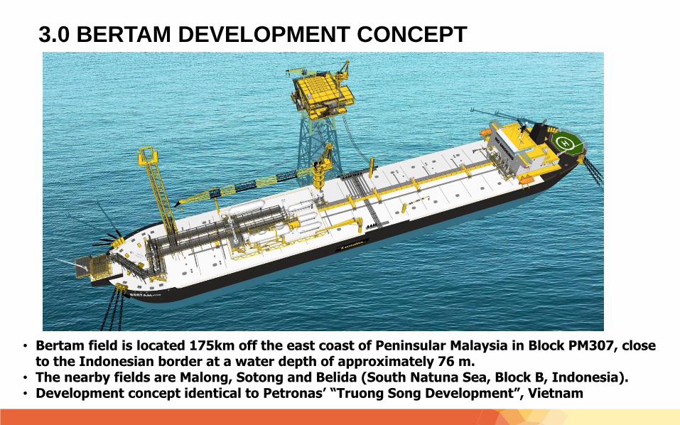
• Bertam field is located 175km off the east coast of Peninsular Malaysia in Block PM307, close to the Indonesian border at a water depth of approximately 76 m.
• The nearby fields are Malong, Sotong and Belida (South Natuna Sea, Block B, Indonesia). • Development concept identical to Petronas’ “Truong Song Development”, Vietnam
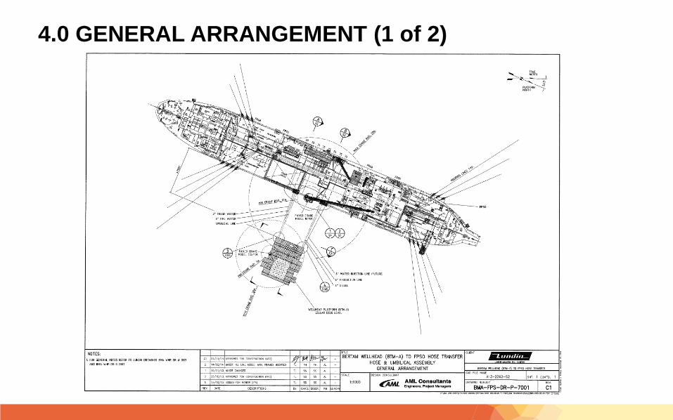
4.0 GENERAL ARRANGEMENT (1 of 2)
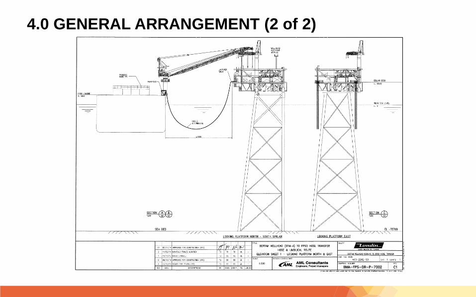
4.0 GENERAL ARRANGEMENT (2 of 2)
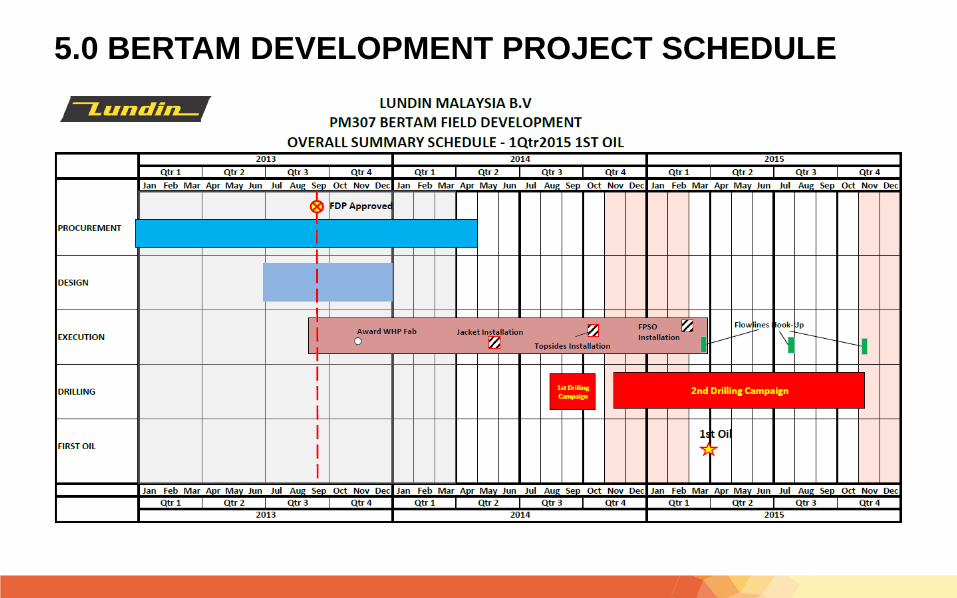
5.0 BERTAM DEVELOPMENT PROJECT SCHEDULE
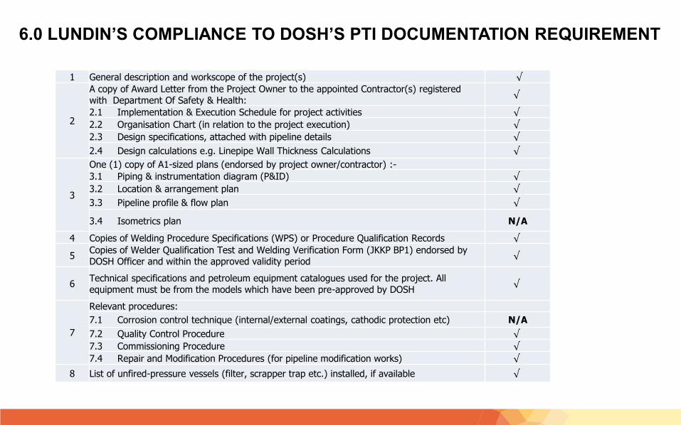
1 General description and workscope of the project(s) √
2
A copy of Award Letter from the Project Owner to the appointed Contractor(s) registered with Department Of Safety & Health:
√
2.1 Implementation & Execution Schedule for project activities √
2.2 Organisation Chart (in relation to the project execution) √
2.3 Design specifications, attached with pipeline details √
2.4 Design calculations e.g. Linepipe Wall Thickness Calculations √
3
One (1) copy of A1-sized plans (endorsed by project owner/contractor) :-
3.1 Piping & instrumentation diagram (P&ID) √
3.2 Location & arrangement plan √
3.3 Pipeline profile & flow plan √
3.4 Isometrics plan N/A
4 Copies of Welding Procedure Specifications (WPS) or Procedure Qualification Records √
5Copies of Welder Qualification Test and Welding Verification Form (JKKP BP1) endorsed by DOSH Officer and within the approved validity period
√
6Technical specifications and petroleum equipment catalogues used for the project. All equipment must be from the models which have been pre-approved by DOSH
√
7
Relevant procedures:
7.1 Corrosion control technique (internal/external coatings, cathodic protection etc) N/A
7.2 Quality Control Procedure √
7.3 Commissioning Procedure √
7.4 Repair and Modification Procedures (for pipeline modification works) √
8 List of unfired-pressure vessels (filter, scrapper trap etc.) installed, if available √
6.0 LUNDIN’S COMPLIANCE TO DOSH’S PTI DOCUMENTATION REQUIREMENT
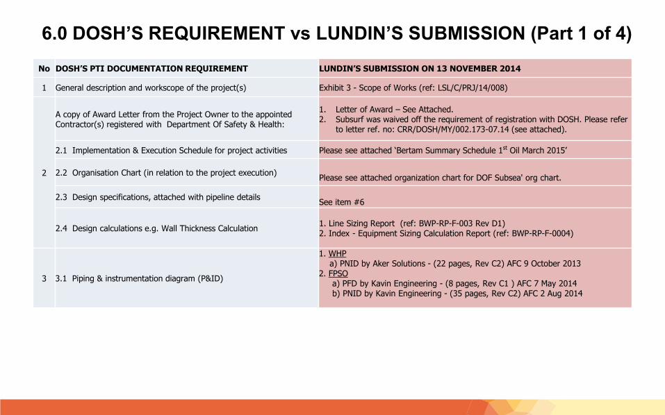
6.0 DOSH’S REQUIREMENT vs LUNDIN’S SUBMISSION (Part 1 of 4)
No DOSH’S PTI DOCUMENTATION REQUIREMENT LUNDIN’S SUBMISSION ON 13 NOVEMBER 2014
1 General description and workscope of the project(s) Exhibit 3 - Scope of Works (ref: LSL/C/PRJ/14/008)
2
A copy of Award Letter from the Project Owner to the appointed Contractor(s) registered with Department Of Safety & Health:
1. Letter of Award – See Attached.2. Subsurf was waived off the requirement of registration with DOSH. Please refer
to letter ref. no: CRR/DOSH/MY/002.173-07.14 (see attached).
2.1 Implementation & Execution Schedule for project activities Please see attached ‘Bertam Summary Schedule 1st Oil March 2015’
2.2 Organisation Chart (in relation to the project execution)Please see attached organization chart for DOF Subsea' org chart.
2.3 Design specifications, attached with pipeline detailsSee item #6
2.4 Design calculations e.g. Wall Thickness Calculation1. Line Sizing Report (ref: BWP-RP-F-003 Rev D1)2. Index - Equipment Sizing Calculation Report (ref: BWP-RP-F-0004)
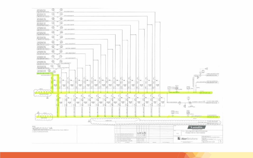
3 3.1 Piping & instrumentation diagram (P&ID)
1. WHPa) PNID by Aker Solutions - (22 pages, Rev C2) AFC 9 October 2013
2. FPSOa) PFD by Kavin Engineering - (8 pages, Rev C1 ) AFC 7 May 2014b) PNID by Kavin Engineering - (35 pages, Rev C2) AFC 2 Aug 2014
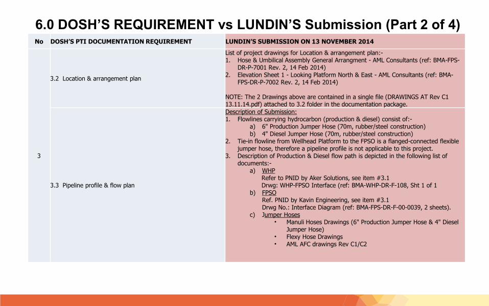
6.0 DOSH’S REQUIREMENT vs LUNDIN’S Submission (Part 2 of 4)No DOSH’S PTI DOCUMENTATION REQUIREMENT LUNDIN’S SUBMISSION ON 13 NOVEMBER 2014
3
3.2 Location & arrangement plan
List of project drawings for Location & arrangement plan:-1. Hose & Umbilical Assembly General Arrangment - AML Consultants (ref: BMA-FPS-
DR-P-7001 Rev. 2, 14 Feb 2014)2. Elevation Sheet 1 - Looking Platform North & East - AML Consultants (ref: BMA-
FPS-DR-P-7002 Rev. 2, 14 Feb 2014)
NOTE: The 2 Drawings above are contained in a single file (DRAWINGS AT Rev C1 13.11.14.pdf) attached to 3.2 folder in the documentation package.
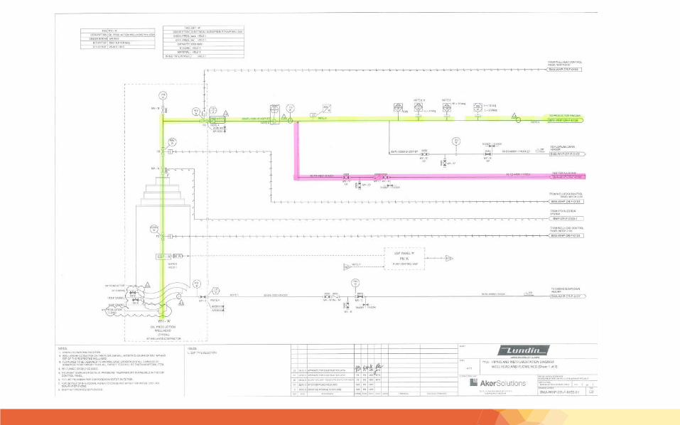
3.3 Pipeline profile & flow plan
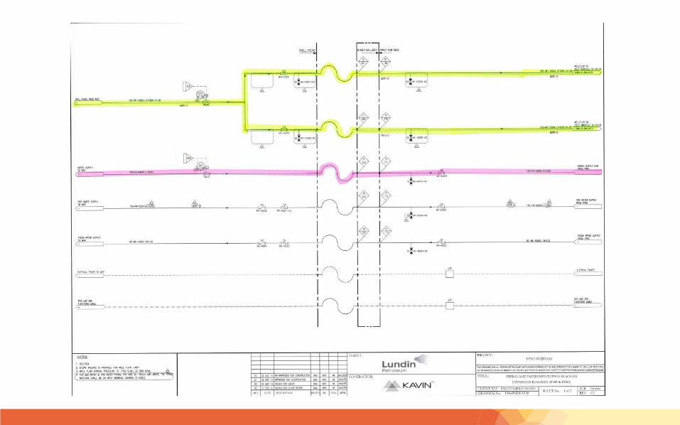
Description of Submission:1. Flowlines carrying hydrocarbon (production & diesel) consist of:-
a) 6" Production Jumper Hose (70m, rubber/steel construction)b) 4" Diesel Jumper Hose (70m, rubber/steel construction)
2. Tie-in flowline from Wellhead Platform to the FPSO is a flanged-connected flexible jumper hose, therefore a pipeline profile is not applicable to this project.
3. Description of Production & Diesel flow path is depicted in the following list of documents:-
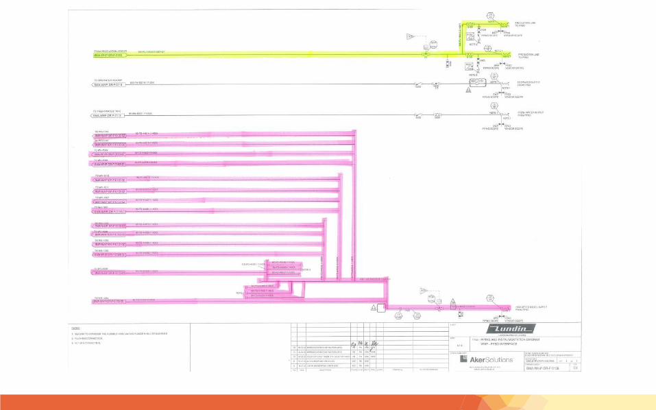
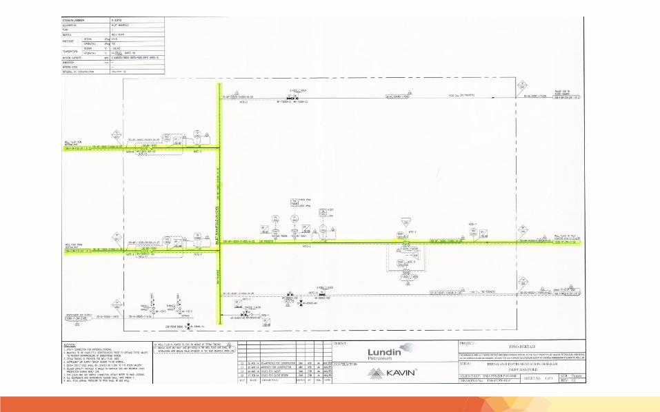
a) WHPRefer to PNID by Aker Solutions, see item #3.1Drwg: WHP-FPSO Interface (ref: BMA-WHP-DR-F-108, Sht 1 of 1
b) FPSORef. PNID by Kavin Engineering, see item #3.1Drwg No.: Interface Diagram (ref: BMA-FPS-DR-F-00-0039, 2 sheets).
c) Jumper Hoses• Manuli Hoses Drawings (6" Production Jumper Hose & 4" Diesel
Jumper Hose)• Flexy Hose Drawings • AML AFC drawings Rev C1/C2
6.0 DOSH’S REQUIREMENT vs LUNDIN’S Submission (Part 3 of 4)
No DOSH’S PTI DOCUMENTATION REQUIREMENT LUNDIN’S SUBMISSION ON 13 NOVEMBER 2014
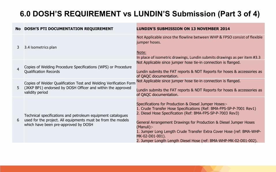
3 3.4 Isometrics plan
Not Applicable since the flowline between WHP & FPSO consist of flexible jumper hoses.
Note:In place of isometric drawings, Lundin submits drawings as per item #3.3
4Copies of Welding Procedure Specifications (WPS) or Procedure Qualification Records
Not Applicable since jumper hose tie-in connection is flanged.
Lundin submits the FAT reports & NDT Reports for hoses & accessories as of QAQC documentation.
5Copies of Welder Qualification Test and Welding Verification Form (JKKP BP1) endorsed by DOSH Officer and within the approved validity period
Not Applicable since jumper hose tie-in connection is flanged.
Lundin submits the FAT reports & NDT Reports for hoses & accessories as of QAQC documentation.
6Technical specifications and petroleum equipment catalogues used for the project. All equipments must be from the models which have been pre-approved by DOSH
Specifications for Production & Diesel Jumper Hoses:-1. Crude Transfer Hose Specifications (Ref: BMA-FPS-SP-P-7001 Rev1)2. Diesel Hose Specification (Ref: BMA-FPS-SP-P-7003 Rev3)
General Arrangement Drawings for Production & Diesel Jumper Hoses (Manuli):-1. Jumper Long Length Crude Transfer Extra Cover Hose (ref: BMA-WHP-MK-02-D01-001).2. Jumper Longth Length Diesel Hose (ref: BMA-WHP-MK-02-D01-002).
6.0 DOSH’S REQUIREMENT vs LUNDIN’S Submission (Part 3 of 4)
No DOSH’S PTI DOCUMENTATION REQUIREMENT LUNDIN’S SUBMISSION ON 13 NOVEMBER 2014
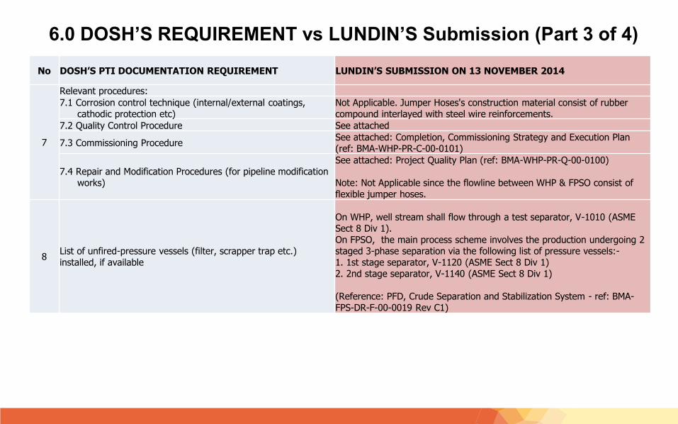
7
Relevant procedures:
7.1 Corrosion control technique (internal/external coatings,cathodic protection etc)
Not Applicable. Jumper Hoses's construction material consist of rubber compound interlayed with steel wire reinforcements.
7.2 Quality Control Procedure See attached
7.3 Commissioning ProcedureSee attached: Completion, Commissioning Strategy and Execution Plan (ref: BMA-WHP-PR-C-00-0101)
7.4 Repair and Modification Procedures (for pipeline modification works)
See attached: Project Quality Plan (ref: BMA-WHP-PR-Q-00-0100)
Note: Not Applicable since the flowline between WHP & FPSO consist of flexible jumper hoses.
8List of unfired-pressure vessels (filter, scrapper trap etc.) installed, if available
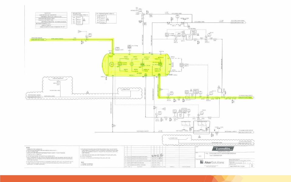
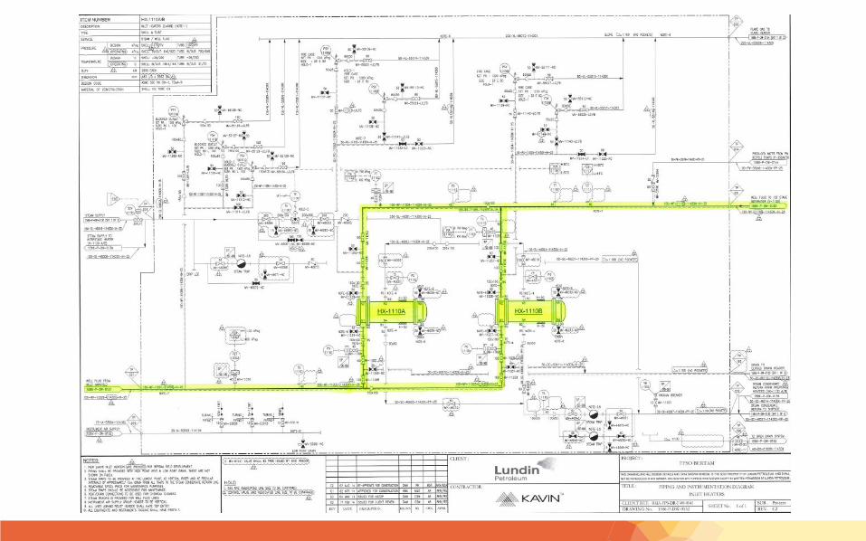
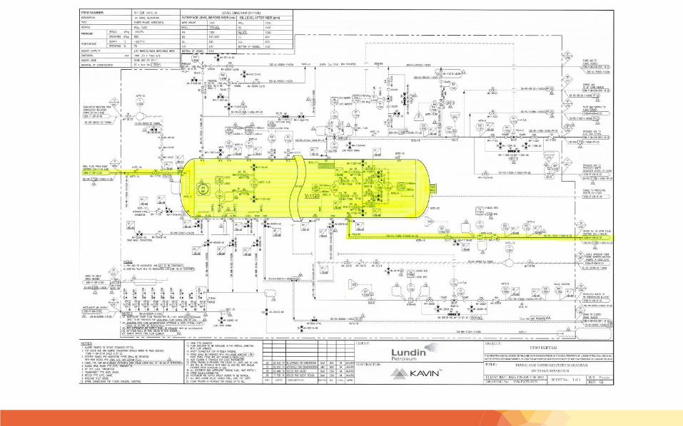
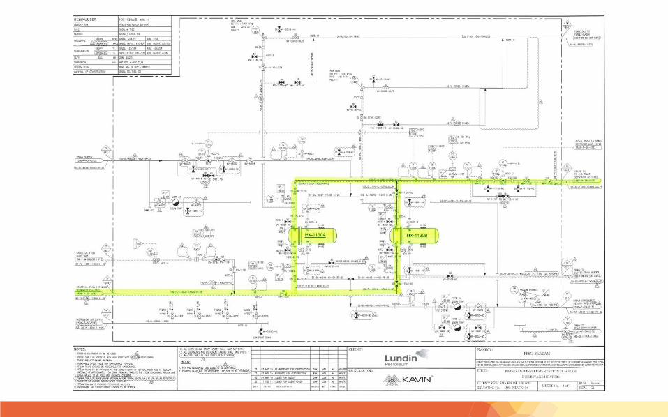
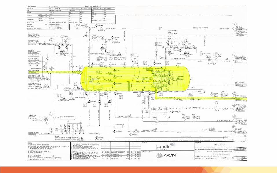
On WHP, well stream shall flow through a test separator, V-1010 (ASME Sect 8 Div 1). On FPSO, the main process scheme involves the production undergoing 2 staged 3-phase separation via the following list of pressure vessels:-1. 1st stage separator, V-1120 (ASME Sect 8 Div 1) 2. 2nd stage separator, V-1140 (ASME Sect 8 Div 1)
(Reference: PFD, Crude Separation and Stabilization System - ref: BMA-FPS-DR-F-00-0019 Rev C1)
7.0 BERTAM PRODUCTION FLOW PLAN/PATH
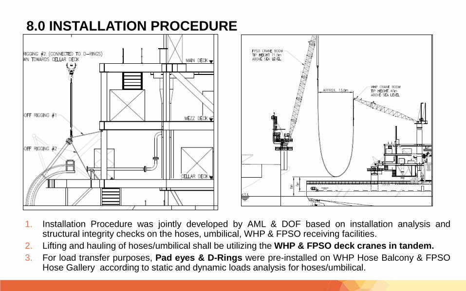
1. Installation Procedure was jointly developed by AML & DOF based on installation analysis andstructural integrity checks on the hoses, umbilical, WHP & FPSO receiving facilities.
2. Lifting and hauling of hoses/umbilical shall be utilizing the WHP & FPSO deck cranes in tandem.
3. For load transfer purposes, Pad eyes & D-Rings were pre-installed on WHP Hose Balcony & FPSOHose Gallery according to static and dynamic loads analysis for hoses/umbilical.
8.0 INSTALLATION PROCEDURE
9.0 QUALITY ASSURANCE & QUALITY CONTROL OF JUMPER HOSES & ACCESSORIES
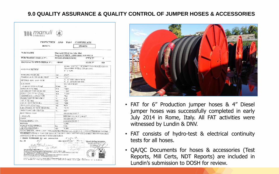
• FAT for 6” Production jumper hoses & 4” Dieseljumper hoses was successfully completed in earlyJuly 2014 in Rome, Italy. All FAT activities werewitnessed by Lundin & DNV.
• FAT consists of hydro-test & electrical continuitytests for all hoses.
• QA/QC Documents for hoses & accessories (TestReports, Mill Certs, NDT Reports) are included inLundin’s submission to DOSH for review.

THANK YOU

Back-up Slides
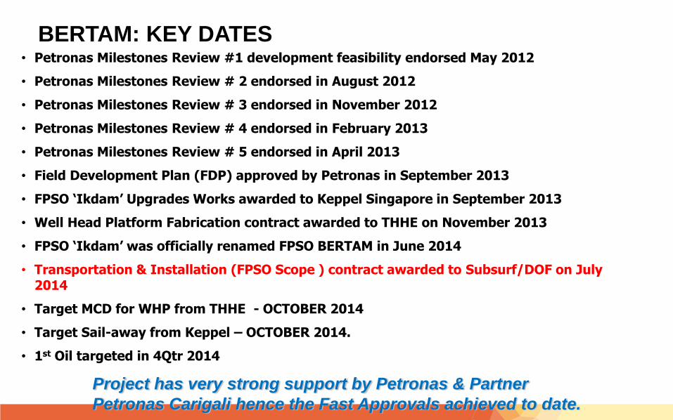
BERTAM: KEY DATES• Petronas Milestones Review #1 development feasibility endorsed May 2012
• Petronas Milestones Review # 2 endorsed in August 2012
• Petronas Milestones Review # 3 endorsed in November 2012
• Petronas Milestones Review # 4 endorsed in February 2013
• Petronas Milestones Review # 5 endorsed in April 2013
• Field Development Plan (FDP) approved by Petronas in September 2013
• FPSO ‘Ikdam’ Upgrades Works awarded to Keppel Singapore in September 2013
• Well Head Platform Fabrication contract awarded to THHE on November 2013
• FPSO ‘Ikdam’ was officially renamed FPSO BERTAM in June 2014
• Transportation & Installation (FPSO Scope ) contract awarded to Subsurf/DOF on July 2014
• Target MCD for WHP from THHE - OCTOBER 2014
• Target Sail-away from Keppel – OCTOBER 2014.
• 1st Oil targeted in 4Qtr 2014
Project has very strong support by Petronas & Partner
Petronas Carigali hence the Fast Approvals achieved to date.
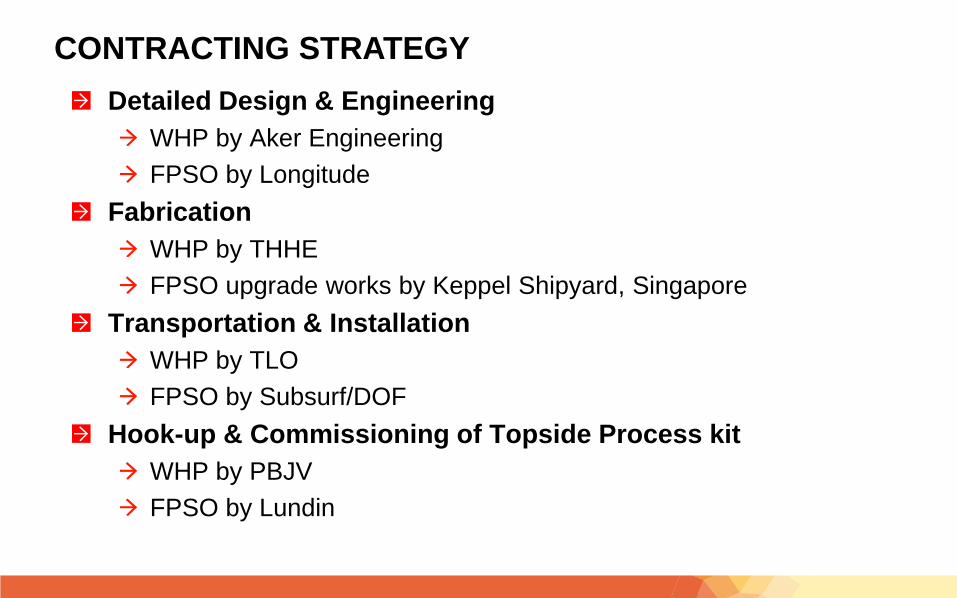
CONTRACTING STRATEGY
Detailed Design & Engineering
WHP by Aker Engineering
FPSO by Longitude
Fabrication
WHP by THHE
FPSO upgrade works by Keppel Shipyard, Singapore
Transportation & Installation
WHP by TLO
FPSO by Subsurf/DOF
Hook-up & Commissioning of Topside Process kit
WHP by PBJV
FPSO by Lundin
TRANSPORTATION & INSTALLATION SCOPE OF WORKS – SUBSURF/DOF
1. Phase 1 – Installation of Mooring Piles and Mooring Chains
• Successfully completed on 2 August 2014
2. Phase 2 – Hook up of FPSO to Pre-laid Mooring Chains
• To commence on late October/November 2014
3. Phase 3 – Installation of Hoses and Umbilical
• To commence on November 2014
* Prior to start-up, full Nitrogen leak test will be done on the flexible hoses (production &
diesel lines).

CONTRACTING STRATEGY
Detailed Design & Engineering
WHP by Aker Engineering
FPSO by Longitude
Fabrication
WHP by THHE
FPSO upgrade works by Keppel Shipyard, Singapore
Transportation & Installation
WHP by TLO
FPSO by Subsurf/DOF
Hook-up & Commissioning of Topside Process
WHP by PBJV
FPSO by Lundin
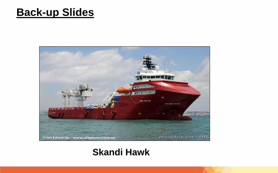
Back-up Slides
Skandi Hawk
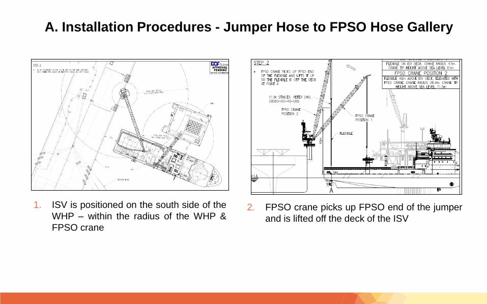
1. ISV is positioned on the south side of the
WHP – within the radius of the WHP &
FPSO crane
2. FPSO crane picks up FPSO end of the jumper
and is lifted off the deck of the ISV
A. Installation Procedures - Jumper Hose to FPSO Hose Gallery
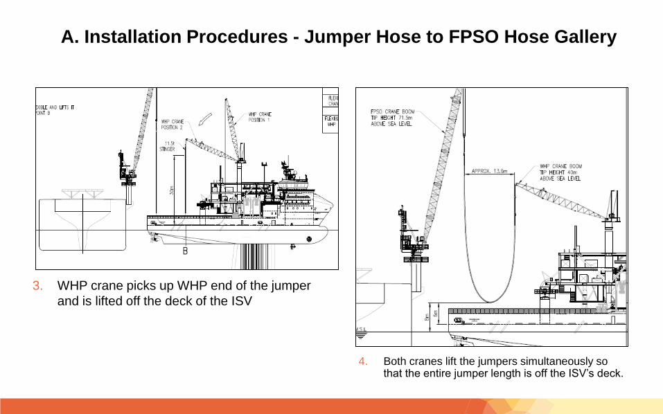
3. WHP crane picks up WHP end of the jumper
and is lifted off the deck of the ISV
4. Both cranes lift the jumpers simultaneously so that the entire jumper length is off the ISV’s deck.
A. Installation Procedures - Jumper Hose to FPSO Hose Gallery
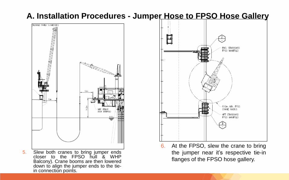
5. Slew both cranes to bring jumper endscloser to the FPSO hull & WHPBalcony). Crane booms are then lowereddown to align the jumper ends to the tie-in connection points.
6. At the FPSO, slew the crane to bring
the jumper near it’s respective tie-in
flanges of the FPSO hose gallery.
A. Installation Procedures - Jumper Hose to FPSO Hose Gallery

7. Lift jumper end to FPSO deck level.
Connect hang-off rigging to soft slings
c/w lifting spool lugs on jumpers.
8. Transfer load from FPSO crane to hang-off rigging
and remove lifting flange..
A. Installation Procedures - Jumper Hose to FPSO Hose Gallery
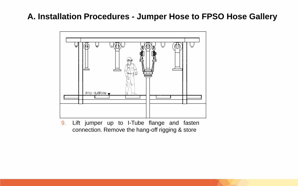
9. Lift jumper up to I-Tube flange and fasten
connection. Remove the hang-off rigging & store
A. Installation Procedures - Jumper Hose to FPSO Hose Gallery
A. Installation Procedures - Jumper Hose to WHP Balcony
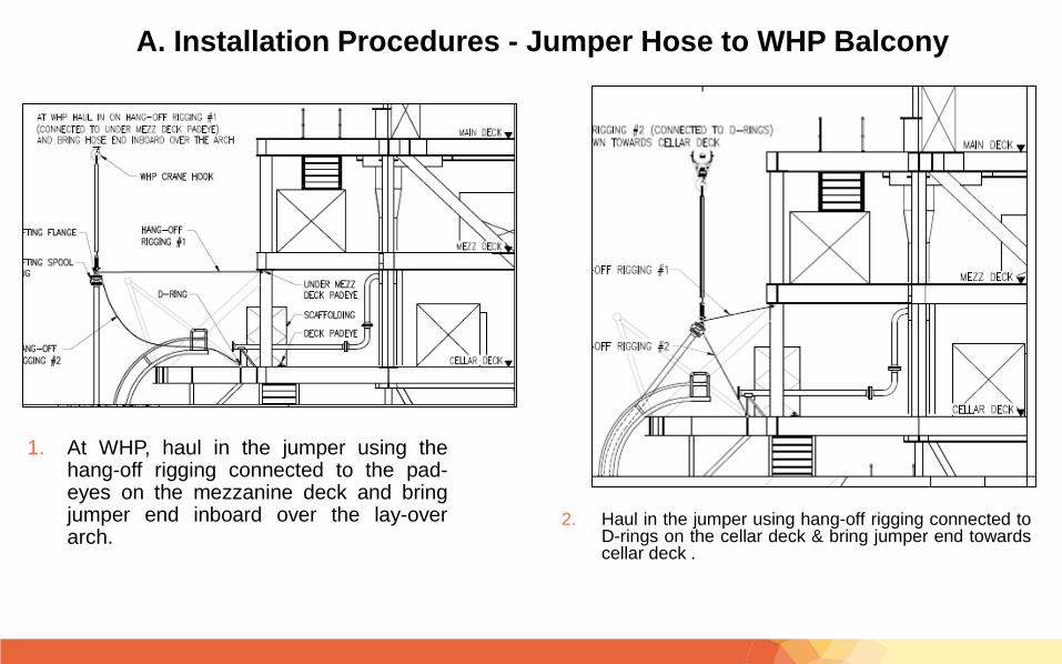
1. At WHP, haul in the jumper using thehang-off rigging connected to the pad-eyes on the mezzanine deck and bringjumper end inboard over the lay-overarch.
2. Haul in the jumper using hang-off rigging connected toD-rings on the cellar deck & bring jumper end towardscellar deck .
A. Installation Procedures - Jumper Hose to WHP Balcony
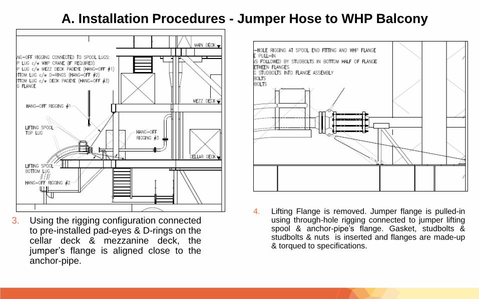
3. Using the rigging configuration connectedto pre-installed pad-eyes & D-rings on thecellar deck & mezzanine deck, thejumper’s flange is aligned close to theanchor-pipe.
4. Lifting Flange is removed. Jumper flange is pulled-inusing through-hole rigging connected to jumper liftingspool & anchor-pipe’s flange. Gasket, studbolts &studbolts & nuts is inserted and flanges are made-up& torqued to specifications.


![TESS DOSH[1]](https://img.pdfslide.net/doc/110x75/577d248a1a28ab4e1e9cb30a/tess-dosh1.jpg)