Embed Size (px)
Citation preview

Anleitung_T900_englisch_V010703
Precision Measuring Instrument T900-series English language Operation manual
DOSTMANN electronic

Summary 1. Handling
1.1. General advices 1.2. Setting to work 1.3. Switch on/off 1.4. Menu
1.4.1. Measuring unit switching (Unit) 1.4.2. Probe selection (Prob) 1.4.3. Difference temperature (Lin2) 1.4.4. Calibration (CAL) 1.4.4.1 Calibration combination probe (temperature/humidity) 1.4.5. Printer port (PrEn) 1.4.6. Channel activation (Chnl) 1.4.7. Analogue output dAC
1.5. Recalling memory data (HOLD/MAX/MIN/AVG) 1.6. Measuring rate (FAST-modus) 1.7. AUTO-OFF-function 1.8. Special-functions
2. Power supply / Changing the battery 3. Error codes / troubleshooting 4. Technical data 5. Interface protocol RS232 6. Connector layout 7. Data of probe-calibration 8. Connector layout 9. Guarantee

1. Handling
1.1 General advice
- For cleaning the instrument please do not use abrasive cleaner but a dry or wet piece of cloth.
- Please store the measuring instrument in a dry and clean place. - Avoid any force like shocks or pressure to the instrument. - Do not use force to connect the probe or interface plugs in. The interface
plug is different from the probe plug. - If no sensor is connected to the instrument while switching on „open“ shows
on the display (Please refer to chapter error codes/troubleshooting). - A retractable stand on the back of the instrument allows it to be used as a
bench top instrument. 1.2 Operation
Connect the mains plug with a 230V / 50Hz socket on the rear side. Before switch on the instrument connect the probes on the instrument and take in the calibration number, which is marked on the handle. On the front there are the two probe plugs marked with 1 and 2.
1.3 Switching on and off By operating the ON/OFF-key the instrument switched on or off. After switching on the instrument indicates a full segment test for 1,5 sec., afterwards the instrument shows the calibration-code and the adjusted measurement category for channel 1. (Only 2-channel instruments: After additionally 1,5 sec. the instrument shows the calibration-code and the adjusted measurement category for channel 2.) Then it starts operating in measurement mode indicating the actual measurement value (for example: temperature). All instruments display the measurement value of channel 1 on the top display line (big display line). Directly below you will see the trending bargraph. The second channel of our 2-channel instruments you will see on the bottom line (small display line).
Fig 1.: Example of channel information after switching on.: channel 1: Line 1: [oFF P = calibration code of channel 1 according to DIN, probe selection of channel 1 = Pt100. channel 2: Line 2: [oFF P = calibration code of channel 2 according to DIN, probe selection of channel 2 = Pt100.
Note: On all instruments you can select the measurement category (chapter 1.4.2. Prob) according to the model version. Instruments that are delivered only with one probe the correct measurement category is preset. In other case please check chapter 1.4.2. (Prob) for the correct set-up.

1.4 Menu
The adjustments of the instruments like the measurement value, calibration of probes, deactivation of channels and so on are resulting from the structure of the menu. You will reach into the main menu by pressing [ENTER/MENUE]. With the up and down keys [éê] you can choose your required menu item. Press [ESC] to be back in the measuring mode. key [ESC] key [ENTER/MENUE]
Menu structure
Unit für Kanal 1+2
Prob für Kanal 1+2
Lin2
CAL für Kanal 1+2
PrEn
Chnl für Kanal 1+2
dAC für Kanal 1+2
°C P T1-T2 oFF oFF oFF dA1b
°F J oP1 on on dA1E
m/s t oP2
%rh L
g/m³ n
°C td r
°F td S T M rh d
1.4.1 Measuring unit switching °C and °F respective %rH, td or g/m³ / [Unit] Unit = Measuring unit Measuring unit temperature (°C=Celsius, F°=Fahrenheit) Measuring unit humidity (%rH=relative humidity, td=dew point, g/m³=absolute humidity) To change the measuring unit press [ENTER/MENUE]. Use the up and down keys [éê] to select Unit. Press again [ENTER/MENUE]. On the left corner of the display appears a small 1, which indicates the selected channel. For changing the channel use the up and down keys [éê]. Press [ENTER/MENUE] to confirm. On the right corner of the display appears °C or °F, or %rH, td or gm³ (depending on the selected probe). Use the up and down keys [éê] again to adjust the requested measuring unit and press [ENTER/MENUE] to confirm. Press [ESC] to be back in the measuring mode.
MENUE
Unit Prob Lin2 CAL PrEn Chnl dAC
Up and down keys

1.4.2 Probe selection / [Prob] Press [ENTER/MENUE] to change a probe. Use the up and down keys [éê] to select Prob. Press [ENTER/MENUE] to confirm. On the left corner of the display appears a small 1, which indicates the selected channel. For changing the channel use the up and down keys [éê]. Press again [ENTER/MENUE] to confirm. On the right corner of the display appears the active probe. Use the up and down keys [éê] to change the probe. Press [ENTER/MENUE] to confirm the requested probe. Press [ESC] to be back in the measuring mode.
MENUE
Unit Prob Lin2 CAL PrEn Chnl dAC Available probes: Measurement Probe selection LC-Display Suitable for these types of
category (Prob) measuring instruments:
Temperature Pt100 (RTD) T905/T955
Temperature Fe-CuNi Type J T905/T955
Temperature NiCr-Ni Type K T905/T955
Temperature Fe-CuNi Type L T905/T955
Temperature NiCrSi-NiSi Type N T905/T955
Temperature Pt13Rh-Pt Type R T905/T955
Temperature Pt10Rh-Pt Type S T905/T955
Temperature Cu-CuNi Type T T905/T955
Humidity %rH T955
Flow m/s T955

Note: Please check the probe selection to be sure that the correct probe is entered. If a measurement value is changed with the ENTER-key at the menu Prob, the standard calibration will be automatically used. Indications for the combination probes (temperature and humidity): Please adjust relatively humidity as measurement value for the channel on which the combination probe is plugged. If you want that the measured temperature of the plugged combination probe is shown as well, you have to deactivate the channel on which no probe is plugged on (see chapter 1.4.6./Chnl) 1.4.3 Difference temperature (only 2-channel instruments) / [Lin2] To display the difference temperature press [ENTER/MENUE]. Use the up and down keys [éê] to select Lin2. Press again [ENTER/MENUE]. On the right corner of the display appears a T1-T2. Use the up and down keys [éê] to adjust the requested
selection. Press [ENTER/MENUE] to confirm. Press [ESC] to be back in the measuring mode.
MENUE
Unit Prob Lin2 CAL PrEn Chnl dAC Note: Both channel have to be activated for showing the difference temperature.

5.4.4 Calibration function / [CAL] Despite high quality manufacturing techniques, each probe is slightly different from specified standards. To eliminate inaccuracies caused by exchanging or ageing of probes, the instrument offer easy calibration functions which guarantee that the system accuracy is always as good as if the instrument was specifically calibrated to the individual probes in our laboratory. The instruments offer three calibration options: 1) [OFF]:Standard characteristic curve (e.g. Pt100-resistance according DIN IEC
60751) 2) [OP1]:Calibration by code (2 x four digit code) is equivalent to a 2-point
calibration The code is marked clearly by a label on each standard probe.
3) [OP2]:Calibration by physical standard references (1-point, 2-point or 3-point calibration)
CAL = calibration Press [ENTER/MENUE] to calibrate the instrument with sensor. Use the up and down keys [éê] to select CAL. Press again [ENTER/MENUE]. On the left corner of the display appears a small 1, which indicates the selected channel. For changing the channel use the up and down keys [éê]. Press [ENTER/MENUE] to confirm
MENUE
Unit Prob Lin2 CAL PrEn Chnl dAC Use the up and down keys [éê] to select the requested calibration option. Press [ENTER/MENUE] to confirm.
CAL
oFF oP1 oP2 Standard calibration according DIN IEC 60751 / [oFF Use the up and down keys [éê] to select [oFF. Press [ENTER/MENUE] to confirm. Press [ESC] to be back in the measuring mode. Calibration by code / oP1 Use the up and down keys [éê] to select oP1. Press [ENTER/MENUE] to confirm. On the bottom of the display appears a very small 1, after this number a four-digit number (Hex-Code/0..F) is displayed. For changing the number use the up key [é]. For stepping to the next number use the down key [ê]. If the requested number is complete then press [ENTER/MENUE] to confirm. Now on the bottom of the display appears a very small 2, after this number a second four-digit number is displayed. For changing the number please follow the manual as before. Press [ESC] to be back in the measuring mode. Note: After confirming oP1 by pressing [ENTER/MENUE] the function oP1 (calibration by code) is activated, even though you leave the menu by pressing [ESC].
Display-indication with active calibration code(OP1): The CAL-segment and the small 1 on the left indicates to the user that oP1 is activated.

Calibration by physical standard references / oP2 Use the up and down keys [éê] to select oP2. Press [ENTER/MENUE] to confirm. On the bottom of the display appears 1 P. For changing between a 1-Point 1 P, 2-Point 2 P or 3-Point 3 P - calibration use the up and down keys [éê].
oP2
1 P 2 P 3 P Example of a 1-Point calibration: Press [ENTER/MENUE] to confirm. On the display appears Go. After the displayed measuring value is stabile press [ENTER/MENUE]. App. 2 seconds later in the first display line appears P1 (measuring value 1); in the second display line appears dP. (standing for decimal point). Use the up and down keys [éê] to select the number of digits after decimal point. dP. = two decimal digits dP . = one decimal digit (decimal point is jumping one digit to the right) Press [ENTER/MENUE] to confirm. On the second line of the display appears Si -. Use the up and down keys [éê] to select the requested sign. Si _ = reference standard shows a negative measuring value (below 0,00C°) Si _׀ = reference standard shows a positive measuring value (above 0,00C°) Press [ENTER/MENUE] to confirm. On the second line of the display appears Fd 0. Use the up and down keys [éê] to select the requested range: Fd 0 = below 100,00°C Fd 1 = above 100,00°C Press [ENTER/MENUE] to confirm. On the display appears 00.00. For changing the value use the up key [é]. For stepping to the next number use the down key [ê]. If the requested value is complete then press [ENTER/MENUE] to confirm. Press [ESC] to be back in the measuring mode. Important: A break of the physical calibration cannot be done by the [ESC]-button. Switching off the instrument can only do a break of the physical calibration.
Display-indication with active calibration code(OP2): The CAL-segment and the small 2 on the left indicates to the user that oP2 is activated.

1.4.4.1 Calibration function of the combination probe (humidity/temperature) [CAL] Each humidity probe of Dostmann electronic is a combination probe. That means that beside the humidity sensor these probes also contain a temperature sensor. Both measurement values are plugged in the same channel over one probe. Before the calibrating of both measurement values (humidity and temperature) the calibrated measurement value must be adjusted at the menu item Prob(Probe selection 1.4.2). The instruments offer three calibration options: 1) [OFF]:Standard characteristic curve (no specific probes correction will be carried
out) 2) [OP1]:Calibration by code (2 x four digit code) is equivalent to a 2-point
calibration The code is marked clearly by a label on each standard probe/rH = humidity & P°C = temperature.
3) [OP2]:Calibration by physical standard references (1-point, 2-point or 3-point calibration) is only for the measurement value rH humidity possible
CAL = calibration Press [ENTER/MENUE] to calibrate the instrument with sensor. Use the up and down keys [éê] to select CAL. Press again [ENTER/MENUE]. On the left corner of the display appears a small 1, which indicates the selected channel. For changing the channel use the up and down keys [éê]. Press [ENTER/MENUE] to confirm
MENUE
Unit Prob Lin2 CAL PrEn Chnl dAC With the up and down keys [éê] you can now choose between rH for calibration of humidity and P°C for calibration of temperature.
CAL
rH P °C Use the up and down keys [éê] to select the requested calibration option. Press [ENTER/MENUE] to confirm.
CAL
oFF oP1 oP2 Standard calibration according DIN IEC 60751 / [oFF Use the up and down keys [éê] to select [oFF. Press [ENTER/MENUE] to confirm. Calibration by code / oP1 Use the up and down keys [éê] to select oP1. Press [ENTER/MENUE] to confirm
the desired setting. On the bottom of the display a small 1 appears, after this number a four-digit number (Hex-Code /0..F) is displayed. For changing the number use the up key [é]. For stepping to the next number use the key down [ê]. If the requested number is complete then press [ENTER/MENUE] to confirm. Now on the bottom of the display appears a small 2 and after this number a second
four-digit number is displayed. For changing the number please follow the manual as before. Press [ESC] to be back in the measuring mode.

1.4.5 Printer port / [PrEn] PrEn = Printer enable = Drucker aktivieren Press [ENTER/MENUE] to activate or deactivate the printer port. Use the up and down keys [éê] to select PrEn. Press again [ENTER/MENUE]. Use the up and down keys [éê] to activate on or deactivate off the requested adjustment and press [ENTER/MENUE] to confirm. Press [ESC] to be back in the measuring mode.
MENUE
Unit Prob Lin2 CAL PrEn Chnl dAC 1.4.6 Channel activation (only 2-channel instruments) / [Chnl] Chnl = channel To activate or deactivate a measuring channel press [ENTER/MENUE]. Use the up and down keys [éê] to select Chnl. Press again [ENTER/MENUE]. On the left corner of the display appears a small 1, which indicates the selected channel. For changing the channel use the up and down keys [éê]. Press [ENTER/MENUE] to confirm. Use the up and down keys [éê] again to activate on or deactivate off the requested measuring channel and press [ENTER/MENUE] to confirm. Press [ESC] to be back in the measuring mode. Note: As a minimum one channel is active!
MENUE
Unit Prob Lin2 CAL PrEn Chnl dAC

1.4.7 dAC Analogue output Each instrument of the T900-series contains an analogue output(0-1Volt) per channel. To get the optimal resolution and accuracy it is possible to scale the analogue output by limiting the measuring range. Press [ENTER/MENUE] to change the measuring range(default: 0..100). Use the up and down keys [éê] to select dAC. Press [ENTER/MENUE] to confirm.
MENUE
Unit Prob Lin2 CAL PrEn Chnl dAC On the left corner of the display appears a small 1, which indicates the selected channel. For changing the channel use the up and down keys [éê]. Press again [ENTER/MENUE] to confirm. On the display appears dA1b. To change between measuring range upper limit [dA1E] and measuring range lower limit [dA1b] use the up and down keys [éê]: dA1b = Lower limit (default 00.00) dA1E = Upper limit (default 100.00) Press [ENTER/MENUE] to confirm. Use the up and down keys [éê] to select the number of digits after decimal point. dP. = two decimal digits dP . = one decimal digit (decimal point moves one digit to the right) Press [ENTER/MENUE] to confirm. On the second line of the display appears Si -. Use the up and down keys [éê] to select the requested sign. Si _ = reference standard shows a negative measuring value (below 0,00C°) Si _׀ = reference standard shows a positive measuring value (above 0,00C°) Press [ENTER/MENUE] to confirm. On the second line of the display appears Fd 0. Use the up and down keys [éê] to select the requested range: Fd 0 = below 100,00°C Fd 1 = above 100,00°C Press [ENTER/MENUE] to confirm. On the display appears 00.00. For changing the value use the up key [é]. For stepping to the next number use the down key [ê]. If the requested value is complete then press [ENTER/MENUE] to confirm. Press [ESC] to return to measuring mode. For changing the upper measuring range please repeat the above procedure. Note: The adjustable measuring range limits are corresponding to the selected measuring size[menu Probe]. e. g.: T900-menu scale Meas. range °C Meas. range %rF Analog signal Lower limit dA1b 00.00 00,00°C 0,0%rF 0,000 Volt Upper limit dA1E 10.00 10,00°C 10,00%rF 1,000 Volt

1.5 Recalling the memory data (HOLD MAX MIN AVE) After pressing first time the key [HOLD MAX MIN AVE] the actual value will be hold on the top display line (big display). pressing again the key [HOLD MAX MIN AVE], the saved maximum-, minimum and average value will be displayed in the bottom display line (small display). Note for 2-channel instruments: First the MAX-MIN-AVE-values of channel 1 will be displayed – afterwards the values of the channel 2 will be displayed. Is there only one probe on a 2-channel instrument we suggest to deactivate the channel without probe (menu Chnl). Note: During the recall of the memory data the extremes (MAX MIN) and the average value (AVE) will not be calculated or carried on. Clearing the memory (MAX MIN AVE) Press [CLEAR] key once to erase the stored maximum, minimum and average from memory. On the display appears Clr. – After erasing the memory the instrument automatically switches back to measuring mode indicating the actual measured value again. 1.6 Measuring rate (FAST-mode) Press [FAST/ê] key once to change the measuring rate. Now the measuring rate is app. 4 measurements per second. Press [FAST/ê] key again and the instrument is back in the standard mode (1 measurement per second). Note: In the fast mode the battery consumption is three times higher than in the standard mode. 1.7 AUTO-OFF-function EAoF = Enable Auto-off dAoF = Disable Auto-off Press [ESC/AUTO-OFF] key once. On the display appears EAoF. Now the instrument switches off automatically after app. 30 minutes. Press [ESC/AUTO-OFF] key again. On the display appears dAoF. Now the Auto-Off-function is deactivated. Note: After switching off and on the instrument, the Auto-Off function is automatically deactivated. 1.8 Special-functions (Ohm/Micro volt/Volt/Hertz-display) If you want to get the shown value displayed according to the basic units you will have to press, when you switch on, the keys FAST and ON/OFF at the same time for approximately 3 seconds till the next basic unit appears: o = Ohm (Pt100) H = Hertz (flow m/s) u = Micro volt (thermocouples) U = Volt (humidity)

2. Power supply For the power supply of the instrument 230V AC / 50Hz is used. 3. Error Codes By displaying the following error codes the instrument support the operation of the instrument. 8. Error Meaning oPEn no probe connected /oLo „too low“ below the measuring range /oHi „too high“ above the measuring range /Er1 CJC temperature is above the measuring range /Er2 CJC temperature is below the measuring range

4. Technical data T905 (2 Measuring channels) T955 (2 Measuring channels) Measuring channel 1/2 Pt100, thermocouple: type K, J, Pt100, thermocouple: type K, J, L, N, R, S, T L, N, R, S, T, humidity, flow, Measuring range Pt100 -200...+850°C -200...+850°C Thermocouple according IEC 584(-200..+1760°C) according IEC 584(-200..+1760°C) Ohm - - - 0 ... 400 Ohm Humidity - - - 0 %...100 %rH Flow - - - 0 ... 40 m/s Accuracy Pt100 +-0,1°C from -100°C...+200°C +-0,03°C from -100°C...+150°C otherwise 0,1% +-0,05°C from -200°C...+200°C, otherwise 0,1% Thermocouple R, S +-1,0°C +0,1% +-1,0°C +0,1% Thermocouple K, J, +-0,2°C from 0°C...+200°C +-0,2°C from 0°C...+200°C L, N, T +-0,5°C to 1000°C +-0,5°C to 1000°C +-1,0°C remaining range +-1,0°C remaining range Humidity - - - +-1,5%rH Flow - - - 0,5% Ohm 0,5% 0,5% Resolution 0,1°C 0,01°C from -200°C...+200°C,
otherwise 0,1°C or0,1% and
0,01m/s Outputs RS232-interface (serial printer can be connected), 2 analog outputs 0-1 Volt (11-bit scalable) Connectors DIN 8-pole Working temperature 0°C ... +40°C Display 2-line LCD Housing Metal Dimensions 200 x 200 x 80 mm (LxBxH) Weight 950 g Power supply 230 VAC Order No. 5000-0905 5000-0955

5. RS232 Interface protocol During the data transmission it has to be guaranteed that the tension level for RTS = + 12V and DTR = -12 V are available through the PC. This has to be assured through a regulation code of the software. Parameter: Baud rate 2400 baud Databits 8 Stopbits 2 Parity None To start the data transmission you have to send the following characters. The following index shows you which value can be requested over the interface.
T900 Measuring value 1 + 2 autom. recognize FC (hex) Enabling the keyboard 0 (hex) Attention: By sending the command FC(hex) you will get the complete data, the instrument lock automatically the keyboard. To release the keyboard you have to send the command 0(hex). The datas would be sent in the following format. Data Type = String The length of the string depends on the instrument (a two-channel or one-channel instrument). measuring value 1 unit measuring value 2 unit LF CR
1 2 3 4 5 6 7 8 9 10 11 12 13 14 15 16 17 18 19 20 21 22 23 24 25 26 Example: Turbo Pascal Source-Code for initialisation of the RS232 interface PROCEDURE V24open(com1,com2:Boolean); { initialisation of RS 232 } VAR value : Byte; BEGIN IF com1 THEN BEGIN { initialisation of COM 1 } PORT [$3FB]:=128; { activate baud rate } PORT [$3F8]:= 48; { baud rate - LSB, 2400 baud } PORT [$3F9]:= 0; { baud rate - MSB } PORT [$3FB]:= 7; { 8 Bits, No Parity, 2 Stop } PORT [$3FC]:= 2; { DTR = 0, RTS = 1 } value := PORT [$3F8] { receiving register empty } END; END;
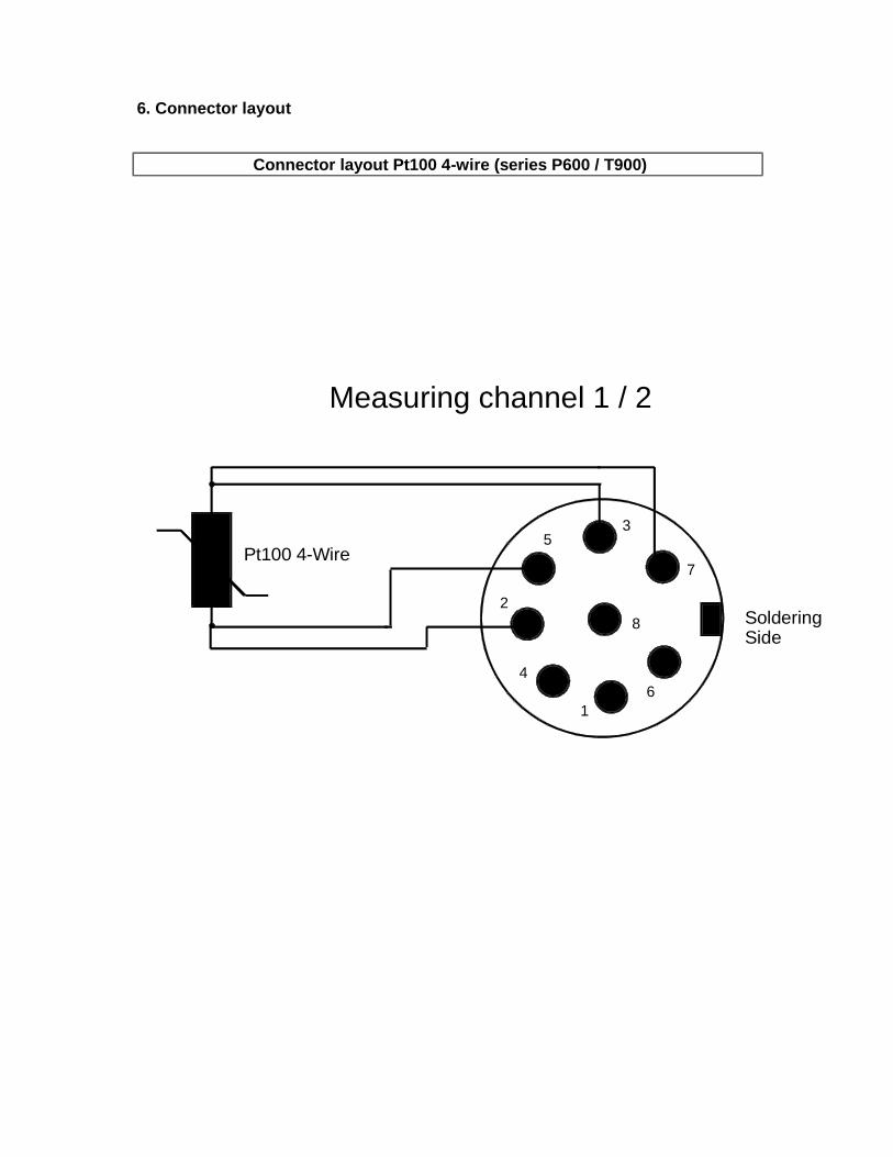
6. Connector layout
Connector layout Pt100 4-wire (series P600 / T900)
Measuring channel 1 / 2
Pt100 4-Wire
8
1
4
2
53
6
7
SolderingSide
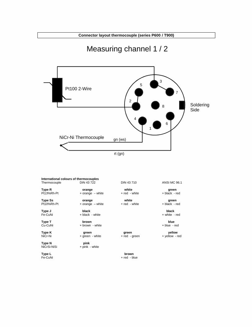
Connector layout thermocouple (series P600 / T900)
Measuring channel 1 / 2
gn (ws)
rt (gn)
Pt100 2-Wire
NiCr-Ni Thermocouple
8
1
4
2
53
6
7
SolderingSide
International colours of thermocouples Thermocouple DIN 43 722 DIN 43 710 ANSI MC 96.1 Type R orange white green Pt13%Rh-Pt + orange – white + red - white + black - red Type Ss orange white green Pt10%Rh-Pt + orange – white + red - white + black - red Type J black black Fe-CuNi + black - white + white - red Type T brown blue Cu-CuNi + brown - white + blue - red Type K green green yellow NiCr-Ni + green - white + red - green + yellow - red Type N pink NiCrSi-NiSi + pink - white Type L brown Fe-CuNi + red - blue

Connector layout of a probe for flow Mini Air6 (series P650/P655/670/T955)
Measuring channel 1 / 2
Mini Air6 Impeller
8
1
4
2
53
6
7
Soldering side
black
white
yellow

Adaptor DIN Connector for Thermocouples Socket (series P600/T900)
K
midget thermocouple connector
+
Pt100 2-Wire
1
gn (ws)
rt (gn)
8
4
2
53
6
7
Solderingside
Measuring channel 1 / 2
cable length 12 cm
International colours for thermocouples Thermocouple DIN 43 722 DIN 43 710 ANSI MC 96.1 Type R orange white green Pt13%Rh-Pt + orange – white + red - white + black - red Type s orange white green Pt10%Rh-Pt + orange – white + red - white + black - red Type J black black Fe-CuNi + black - white + white - red Type T brown blue Cu-CuNi + brown - white + blue - red Type K green ....green yellow NiCr-Ni + green - white + red - green + yellow - red Type N pink NiCrSi-NiSi + pink - white Type L brown Fe-CuNi + red - blue

7. probe-calibration data Our quality-probes are the main reason for the precision and quality of your measuring. To facilitate the exchange of a probe without a loss of precision, our probes were measured in our company and added with a code that describes the characteristic line of the probe. The code is attached well visible on a label on the probe. If you change the probe you have to enter the code into the measuring instrument. In order to avoid any problems later on (esp. if the probe is installed somewhere hard accessible, or if there are several of those external probes in use), we recommend to note down the two values: ID.No.: ________________________ Application: ________________________ Serial number: ________________________ Calibration data: ________________________ ________________________ ________________________ ________________________ ID.No.: ________________________ Application: ________________________ Serial number: ________________________ Calibration data: ________________________ ________________________ ________________________ ________________________ ID.No.: ________________________ Application: ________________________ Serial number: ________________________ Calibration data: ________________________ ________________________ ________________________ ________________________ ID.No.: ________________________ Application: ________________________ Serial number: ________________________ Calibration data: ________________________ ________________________ ________________________ ________________________ ID.No.: ________________________ Application: ________________________ Serial number: ________________________ Calibration data: ________________________ ________________________ ________________________ ________________________

8. Unit diagram
1 Power inlet socket 2 RS232-interface (9-pol)
3 Analogue output(Banana plug) for channel 2 4 Analogue output(Banana plug) for channel 1 5 Operation keys 6 On/off switch
7 Handle/table stand 8 Channel 1 input socket
9 Channel 2 input socket

9. Guarantee With regular normal use, the guarantee lasts 12 months for the instruments and 6 months for the probes and sensors. Opening of the instruments leads to expiration of guarantee. The producer guarantees that his product will not have any material defect or defect in workmanship during the above-mentioned period if the product is correctly used and maintained. Exceptions are defined in the following way: The guarantee does not apply for batteries and fuses. The guarantee does not enclose products that are damaged, used improperly or negligent or stored improper. These guarantee conditions replace all possible expressly or tacitly confirmations. No liability will be assumed for special, casual or constructive damages when it occurs through unauthorized act or through another way even if it is within the contract.