Embed Size (px)
Citation preview

DOT/FAA/AR-04/12 Office of Aviation Research Washington, DC 20591
Aircraft Wiring Harness Shield Degradation Study August 2004 Final Report This document is available to the U.S. public through the National Technical Information Service (NTIS), Springfield, Virginia 22161.
U.S. Department of Transportation Federal Aviation Administration

NOTICE
This document is disseminated under the sponsorship of the U.S. Department of Transportation in the interest of information exchange. The United States Government assumes no liability for the contents or use thereof. The United States Government does not endorse products or manufacturers. Trade or manufacturer's names appear herein solely because they are considered essential to the objective of this report. This document does not constitute FAA certification policy. Consult your local FAA aircraft certification office as to its use. This report is available at the Federal Aviation Administration William J. Hughes Technical Center's Full-Text Technical Reports page: actlibrary.tc.faa.gov in Adobe Acrobat portable document format (PDF).
Technical Report Documentation Page 1. Report No.
DOT/FAA/AR-04/12
2. Government Accession No. 3. Recipient's Catalog No.
5. Report Date
August 2004 4. Title and Subtitle
AIRCRAFT WIRING HARNESS SHIELD DEGRADATION STUDY 6. Performing Organization Code
7. Author(s)
J.B. O’Loughlin and S.R. Skinner 8. Performing Organization Report No.
10. Work Unit No. (TRAIS)
9.Performing Organization Name and Address
National Institute for Aviation Research Wichita State University 1845 Fairmount Avenue Wichita, KS 67260-0093
11. Contract or Grant No.
00-C-WSU-00-28 13. Type of Report and Period Covered
Final Report
12. Sponsoring Agency Name and Address
U.S. Department of Transportation Federal Aviation Administration Office of Aviation Research Washington, DC 20591
14. Sponsoring Agency Code
AIR-100 15. Supplementary Notes
The FAA William J. Hughes Technical Center Technical Monitor was Anthony Wilson. 16. Abstract
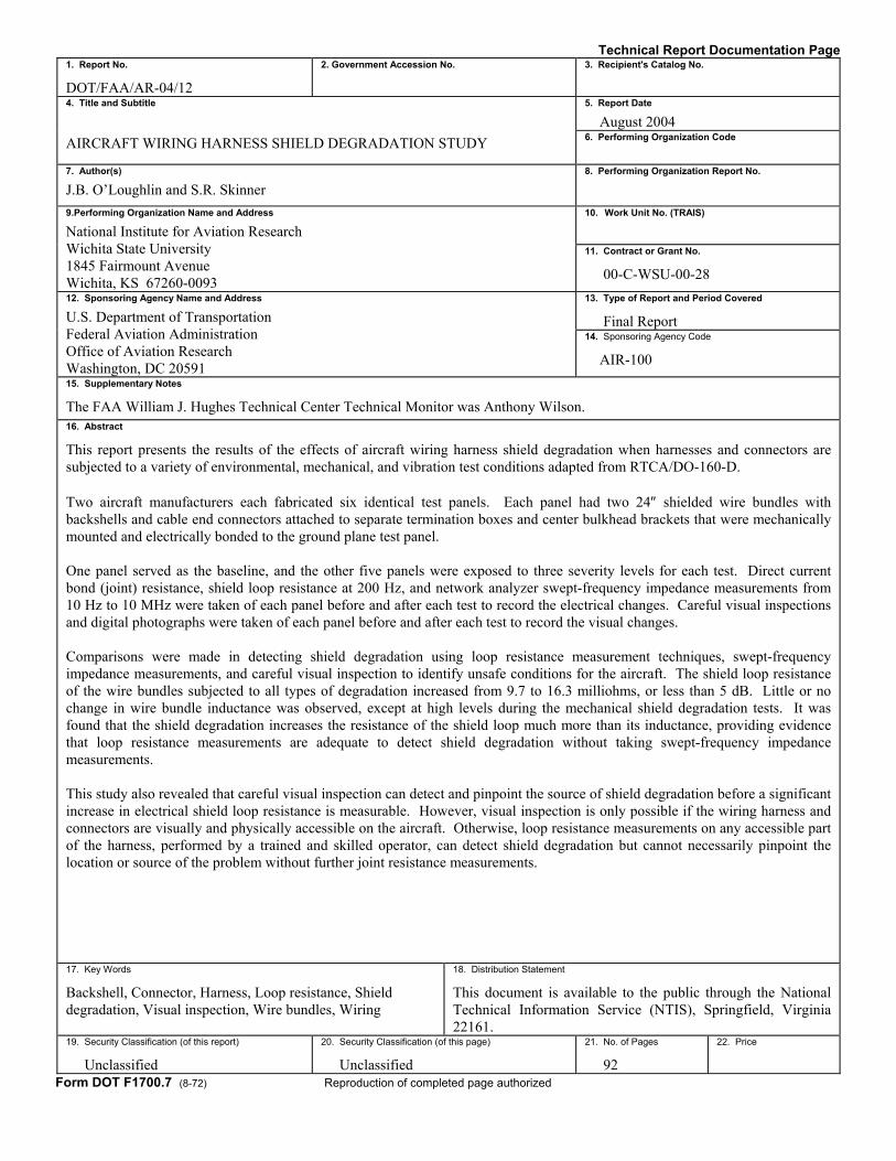
This report presents the results of the effects of aircraft wiring harness shield degradation when harnesses and connectors are subjected to a variety of environmental, mechanical, and vibration test conditions adapted from RTCA/DO-160-D. Two aircraft manufacturers each fabricated six identical test panels. Each panel had two 24″ shielded wire bundles with backshells and cable end connectors attached to separate termination boxes and center bulkhead brackets that were mechanically mounted and electrically bonded to the ground plane test panel. One panel served as the baseline, and the other five panels were exposed to three severity levels for each test. Direct current bond (joint) resistance, shield loop resistance at 200 Hz, and network analyzer swept-frequency impedance measurements from 10 Hz to 10 MHz were taken of each panel before and after each test to record the electrical changes. Careful visual inspections and digital photographs were taken of each panel before and after each test to record the visual changes. Comparisons were made in detecting shield degradation using loop resistance measurement techniques, swept-frequency impedance measurements, and careful visual inspection to identify unsafe conditions for the aircraft. The shield loop resistance of the wire bundles subjected to all types of degradation increased from 9.7 to 16.3 milliohms, or less than 5 dB. Little or no change in wire bundle inductance was observed, except at high levels during the mechanical shield degradation tests. It was found that the shield degradation increases the resistance of the shield loop much more than its inductance, providing evidence that loop resistance measurements are adequate to detect shield degradation without taking swept-frequency impedance measurements. This study also revealed that careful visual inspection can detect and pinpoint the source of shield degradation before a significant increase in electrical shield loop resistance is measurable. However, visual inspection is only possible if the wiring harness and connectors are visually and physically accessible on the aircraft. Otherwise, loop resistance measurements on any accessible part of the harness, performed by a trained and skilled operator, can detect shield degradation but cannot necessarily pinpoint the location or source of the problem without further joint resistance measurements.
17. Key Words
Backshell, Connector, Harness, Loop resistance, Shield degradation, Visual inspection, Wire bundles, Wiring
18. Distribution Statement
This document is available to the public through the National Technical Information Service (NTIS), Springfield, Virginia 22161.
19. Security Classification (of this report)
Unclassified
20. Security Classification (of this page)
Unclassified
21. No. of Pages
92
22. Price
Form DOT F1700.7 (8-72) Reproduction of completed page authorized
ACKNOWLEDGEMENTS
The authors acknowledge the technical assistance, guidance, and review given this study by Billy M. Martin, Charles B. Beuning, Michelle M. Cronkleton, Michael D. Reilly of the Cessna Aircraft Company and by Dr. Leland R. Johnson, Jr., Myrl W. Kelly, Jerry L. Tate and Howard S. Jordan, Jr. of the Raytheon Aircraft Corporation without whose support this effort would not have been possible. Special thanks is also given to the Wichita State University graduate research assistants, Syed Ghayur, Ghulam Awan, Najma Begum, and Fayyaz Khan, who carefully and laboriously collected and organized the data, and professionally and methodically worked through numerous iterations and revisions to help produce this report.
iii/iv

TABLE OF CONTENTS
Page EXECUTIVE SUMMARY xiii 1. INTRODUCTION 1
1.1 Purpose 1 1.2 Test Setup 1
1.2.1 Test Panel Type A 1 1.2.2 Test Panel Type B 4
2. TEST PROCEDURES 4
2.1 Measurement Procedures for the LRT 5 2.2 Measurement Procedures for The HP 8751A Network Analyzer 7 2.3 Measurement Procedures for the Keithley Model 580 Micro-Ohmmeter 8 2.4 Visual Inspection 11 2.5 Resistance-Inductance-Resistance Modeling for Test Panels 11 2.6 Temperature and Altitude Test 12
2.6.1 Test Procedure 12 2.6.2 Results 16 2.6.3 Observations (Temperature and Altitude Tests) 23
2.7 Salt Spray and Humidity Test 24
2.7.1 Test Procedure 24 2.7.2 Results 25 2.7.3 Observations (Salt Spray and Humidity Tests) 34
2.8 Vibration Test 34
2.8.1 Test Procedure 34 2.8.2 Results 36 2.8.3 Observations (Vibration Tests) 41
2.9 Mechanical Degradation Test 41
2.9.1 Test Procedure 41 2.9.2 Results 45 2.9.3 Observations (Mechanical Degradation Tests) 53
v
2.10 Combination Test 53
2.10.1 Test Procedure 53 2.10.2 Results 53 2.10.3 Observations (Combination Tests) 60
3. OVERALL OBSERVATIONS 60
4. REFERENCES 61
5. GLOSSARY 62
APPENDICES
A—Test Procedure for the Boeing Loop Resistance Tester B—Test Procedure for the Hewlett-Packard 8751A Network Analyzer C—Test Procedure for the Keithley Model 580 Micro-Ohmmeter D—Accelerometers and Their Results (Vibration Test)
LIST OF FIGURES
Figure Page 1 Regular Bulkhead (Test Panel Type A) 2
2 Center Bulkhead Modified for Vibration Test (Test Panel Type A) 3
3 Termination Box With End Connector (Test Panel Type A) 3
4 Regular Center Bulkhead (Test Panel Type B) 4
5 Loop 1 Resistance Measurement Using the Boeing LRT (Test Panel Type A) 6
6 Total Loop Resistance Measurement Using the Boeing LRT (Test Panel Type A) 6
7 Network Analyzer Setup for Individual Loop Impedance Measurement 8
8 Network Analyzer Setup for Total Loop Impedance Measurement 8
9 Direct Current Resistance Test Locations (Center Connector) 9
10 Direct Current Resistance Test Locations (End Connector) 10
11 Circuit Diagram for R-L-R Modeling 11
vi
12 Temperatute and Altitude Chamber Test Setup 12
13 Low-Level Temperature and Altitude Variation Test 14
14 Medium-Level Temperature and Altitude Variation Test 15
15 High-Level Temperature and Altitude Variation Test 16
16 Total Loop Impedance Characteristics Before and After Temperature and Altitude Test (Test Panel A1) 18
17 Total Loop Impedance Characteristics Before and After Temperature and Altitude Test (Test Panel B1) 19
18 Percentage Loop Impedance Variation After Temperature and Altitude Test (Test Panel A1) 20
19 Percentage Loop Impedance Variation After Temperature and Altitude Test (Test Panel B1) 20
20 Total Loop Resistance Values for Temperature and Altitude Test Using the Boeing LRT (Test Panel A1) 22
21 Total Loop Resistance Values for Temperature and Altitude Test Using the Boeing LRT (Test Panel B1) 22
22 Salt Spray Chamber Test Setup 24
23 Test Panel Type A After Salt and Humidity Test 25
24 Test Panel Type B After Salt and Humidity Test 26
25 Visible Corrosion After Salt and Humidity Test 26
26 Total Loop Impedance Characteristics Before and After Salt and Humidity Test (Test Panel A2) 29
27 Total Loop Impedance Characteristics Before and After Salt and Humidity Test (Test Panel B2) 30
28 Percentage Loop Impedance Variation After Salt and Humidity Test (Test Panel A2) 31
29 Percentage Loop Impedance Variation After Salt and Humidity Test (Test Panel B2) 31
30 Total Loop Resistance Values for Salt and Humidity Test Using the Boeing LRT (Test Panel A2) 32
vii

31 Total Loop Resistance Values for Salt and Humidity Test Using the Boeing LRT (Test Panel B2) 33
32 Vibration Test Setup for the X and Y Axes (Test Panel Type A) 35
33 Vibration Test Setup for the Z Axis (Test Panel Type A) 35
34 Total Loop Impedance Characteristics Before and After Vibration Test (Test Panel A4) 38
35 Percentage Loop Impedance Variation After Vibration Test (Test Panel A4) 39
36 Total Loop Resistance Values for Vibration Test Using the Boeing LRT (Test Panel A4) 40
37 Low-Level Mechanical Degradation (Test Panel Type A) 42
38 Low-Level Mechanical Degradation (Test Panel Type B) 42
39 Medium-Level Mechanical Degradation (Test Panel Type A) 43
40 Medium-Level Mechanical Degradation (Test Panel Type B) 44
41 High-Level Mechanical Degradation (Test Panel Type A) 44
42 High-Level Mechanical Degradation (Test Panel Type B) 45
43 Total Loop Impedance Characteristics Before and After Mechanical Degradation Test (Test Panel A3) 48
44 Total Loop Impedance Characteristics Before and After Mechanical Degradation Test (Test Panel B1) 49
45 Percentage Loop Impedance Variation After Mechanical Degradation Test (Test Panel A3) 50
46 Percentage Loop Impedance Variation After Mechanical Degradation Test (Test Panel B1) 50
47 Total Loop Resistance Values for Mechanical Degradation Test Using the Boeing LRT (Test Panel A3) 52
48 Total Loop Resistance Values for Mechanical Degradation Test Using the Boeing LRT (Test Panel B1) 52
49 Total Loop Impedance Characteristics Before and After Combination Tests (Test Panel A5) 56
viii

50 Total Loop Resistance Values for Combination Tests Using the Boeing LRT (Test Panel A5) 59
51 Total Loop Resistance Values for Combination Tests Using the Boeing LRT (Test Panel B5) 59
52 Loop Resistance Variation After Each Degradation Test 60
LIST OF TABLES
Table Page 1 Test Matrix 5
2 RTCA/DO-160D Temperature and Altitude Criteria (Partial) 13
3 Impedance Variations Over Frequency Range During Temperature and Altitude Test (Test Panel A1) 17
4 Impedance Variations Over Frequency Range During Temperature and Altitude Test (Test Panel B1) 17
5 Boeing LRT Readings for Temperature and Altitude Test (Test Panel A1) 21
6 Boeing LRT Readings for Temperature and Altitude Test (Test Panel B1) 21
7 Direct Current Measurements for Temperature and Altitude Test (Test Panel A1) 23
8 Severity Level Criteria for Salt Spray and Humidity Test 24
9 Impedance Variations Over Frequency Range During Salt and Humidity Test (Test Panel A2) 27
10 Impedance Variations Over Frequency Range During Salt and Humidity Test (Test Panel B2) 27
11 Boeing LRT Readings for Salt and Humidity Test (Test Panel A2) 32
12 Boeing LRT Readings for Salt and Humidity Test (Test Panel B2) 32
13 Direct Current Measurements for Salt and Humidity Test (Test Panel A2) 33
14 Category and Test Curve and Level Selection (Partial) 34
ix
15 Impedance Variations Over Frequency Range During Vibration Test (Test Panel A4) 37
16 Resistance Values for Vibration Test Using the Boeing LRT (Test Panel A4) 39
17 Direct Current Measurement Variations at Various Levels of Vibration Testing (Test Panel A4) 40
18 Impedance Variations Over Frequency Range During Mechanical Degradation Test (Test Panel A3) 47
19 Impedance Variations Over Frequency Range During Mechanical Degradation Test (Test Panel B1) 47
20 Loop Resistance Values for Mechanical Degradation Test Using the Boeing LRT (Test Panel A3) 51
21 Loop Resistance Values for Mechanical Degradation Test Using the Boeing LRT (Test Panel B1) 51
22 Direct Current Measurements for Mechanical Degradation Test (Test Panel A3) 51
23 Loop Resistance Variations Over Frequency Range During Combination Tests (Test Panel A5) 55
24 Direct Current Measurement Variations for Combination Tests (Test Panel A5) 57
25 Loop Resistance Values for Combination Tests Using the Boeing LRT (Test Panel A5) 58
26 Loop Resistance Values for Combination Tests Using the Boeing LRT (Test Panel B5) 58
x
LIST OF ACRONYMS
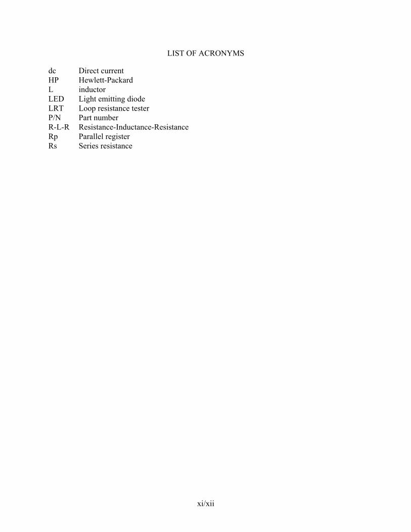
dc Direct current HP Hewlett-Packard L inductor LED Light emitting diode LRT Loop resistance tester P/N Part number R-L-R Resistance-Inductance-Resistance Rp Parallel register Rs Series resistance
xi/xii
EXECUTIVE SUMMARY
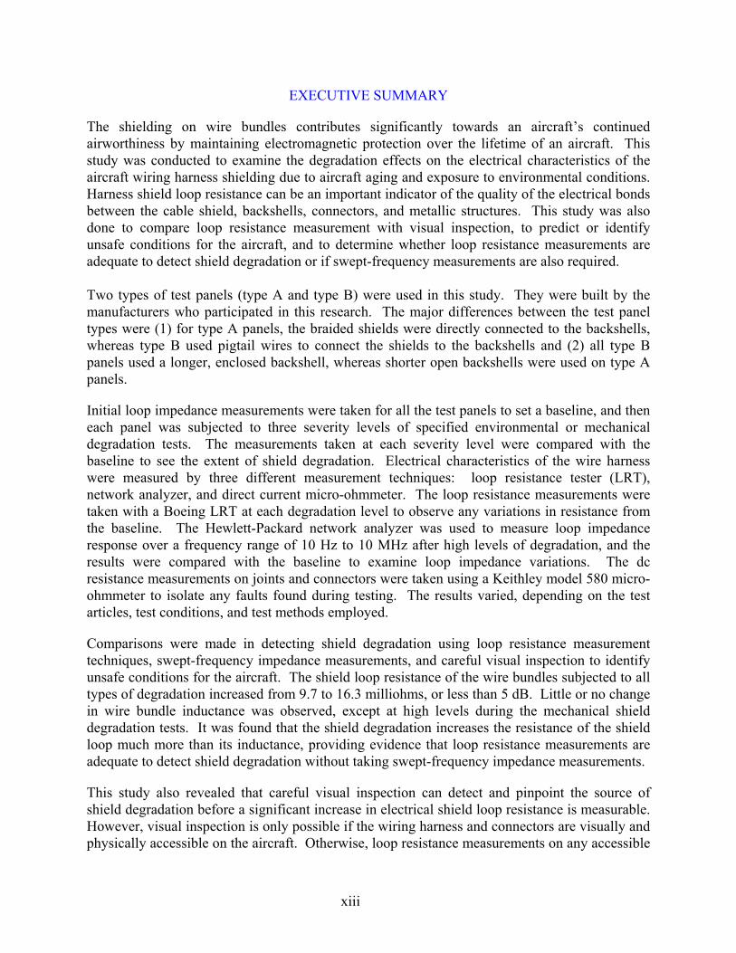
The shielding on wire bundles contributes significantly towards an aircraft’s continued airworthiness by maintaining electromagnetic protection over the lifetime of an aircraft. This study was conducted to examine the degradation effects on the electrical characteristics of the aircraft wiring harness shielding due to aircraft aging and exposure to environmental conditions. Harness shield loop resistance can be an important indicator of the quality of the electrical bonds between the cable shield, backshells, connectors, and metallic structures. This study was also done to compare loop resistance measurement with visual inspection, to predict or identify unsafe conditions for the aircraft, and to determine whether loop resistance measurements are adequate to detect shield degradation or if swept-frequency measurements are also required. Two types of test panels (type A and type B) were used in this study. They were built by the manufacturers who participated in this research. The major differences between the test panel types were (1) for type A panels, the braided shields were directly connected to the backshells, whereas type B used pigtail wires to connect the shields to the backshells and (2) all type B panels used a longer, enclosed backshell, whereas shorter open backshells were used on type A panels.
Initial loop impedance measurements were taken for all the test panels to set a baseline, and then each panel was subjected to three severity levels of specified environmental or mechanical degradation tests. The measurements taken at each severity level were compared with the baseline to see the extent of shield degradation. Electrical characteristics of the wire harness were measured by three different measurement techniques: loop resistance tester (LRT), network analyzer, and direct current micro-ohmmeter. The loop resistance measurements were taken with a Boeing LRT at each degradation level to observe any variations in resistance from the baseline. The Hewlett-Packard network analyzer was used to measure loop impedance response over a frequency range of 10 Hz to 10 MHz after high levels of degradation, and the results were compared with the baseline to examine loop impedance variations. The dc resistance measurements on joints and connectors were taken using a Keithley model 580 micro-ohmmeter to isolate any faults found during testing. The results varied, depending on the test articles, test conditions, and test methods employed.
Comparisons were made in detecting shield degradation using loop resistance measurement techniques, swept-frequency impedance measurements, and careful visual inspection to identify unsafe conditions for the aircraft. The shield loop resistance of the wire bundles subjected to all types of degradation increased from 9.7 to 16.3 milliohms, or less than 5 dB. Little or no change in wire bundle inductance was observed, except at high levels during the mechanical shield degradation tests. It was found that the shield degradation increases the resistance of the shield loop much more than its inductance, providing evidence that loop resistance measurements are adequate to detect shield degradation without taking swept-frequency impedance measurements.
This study also revealed that careful visual inspection can detect and pinpoint the source of shield degradation before a significant increase in electrical shield loop resistance is measurable. However, visual inspection is only possible if the wiring harness and connectors are visually and physically accessible on the aircraft. Otherwise, loop resistance measurements on any accessible
xiii

part of the harness, performed by a trained and skilled operator, can detect shield degradation but cannot necessarily pinpoint the location or source of the problem without further joint resistance measurements.
xiv
1. INTRODUCTION.
1.1 PURPOSE.
In general aviation aircraft, shielded wire bundles are used to provide a significant portion of High-Intensity Radiated Fields protection. Degradation of shielded wires over the lifetime of an aircraft could be critical for continued protection and safety of the aircraft. This study was conducted to observe any change in the electrical characteristics of the shielded wire bundles when they are subjected to all possible environmental and mechanical degradation conditions. This document contains the test procedures and a complete analysis of the environmental and mechanical degradation tests performed on the wire bundles for research by the Federal Aviation Administration and the National Institute for Aviation Research.
1.2 TEST SETUP.
Two types of test panels (type A and type B), built by different manufacturers (manufacturer A and manufacturer B) who participated in the research, were used for testing. The test panels were representative of typical wire bundle types used in general aviation aircraft. Six test panels of type A (A1 through A6) and six panels of type B (B1 through B6) were used for the tests. One test panel of each type was kept as a control and was not exposed to any degradation tests. The following degradation tests were performed on the remaining five test panels.
• Temperature and altitude test • Salt spray and humidity test • Vibration test • Mechanical degradation test • Combination of all degradation tests The test panels were marked for identification and the backshells were tightened to the manufacturer’s specifications and were never retightened during the tests. Each degradation test was performed at a low, medium, and high level of severity. Initial bonding and loop impedance measurements were taken for each test panel to set a baseline. The measurements were taken using a Boeing loop resistance tester (LRT), a Keithley model 580 micro-ohmmeter, and a Hewlett-Packard (HP) 8751A network analyzer throughout the testing.
1.2.1 Test Panel Type A.
Figure 1 shows a type A test panel used to simulate an aircraft structure and act as a ground plane for attachment of the other components. This test setup used a 34″ by 24″ by 1/4″ aluminum panel as the ground plane. U-shaped handling grips are affixed to the panel at the center of each end. Two die-cast aluminum 6″ by 3″ by 3″ termination boxes with removable, screw-on top covers were securely bolted and electrically bonded to the ground plane at the center of each side of the panel, just inside the handling grips. An L-shaped, aluminum sheet metal, regular bulkhead bracket was bolted and bonded to the center of the ground plane panel to support the center cable receptacles. A similar cable receptacle is mounted on the side of each termination box.
1

Simulating an aircraft wiring harness, a 24-inch-long wire bundle with P/N MS3475L16-26P end connectors using Sunbank P/N S4785S16C12 backshells is connected to the receptacle on each termination box and to a center bulkhead receptacle. Each wire bundle was made up of 12 unshielded wires (P/N M81044/12-22) and 12 woven-braid shielded wires (P/N M27500-22-ML-1T08), secured along its length with plastic tie wraps and forming a standard wire bundle configuration. Where each end of the wire bundle enters its backshell, the woven shields were separated from their insulated wires and soldered to a common ground lug terminal that is bolted to the backshell.
Loop 2 0 kΩ
Termination Box
End Connector
Center ConnectorBulkhead
10 kΩ Termination
Box Loop 1
Ground Plane
FIGURE 1. REGULAR BULKHEAD (TEST PANEL TYPE A) These ground lugs can easily be seen at the rear of each wire bundle backshell, as shown in figure 2. The figure shows a center bulkhead bracket modified for vibration testing with a 1/4″ aluminum plate reinforcing the vertical portion of the bracket. A backshell and connector from each wire bundle is attached to the cable receptacles mounted in the bulkhead bracket. One aluminum box, called the 0 kΩ termination box, had all the inner conductors from the cable receptacle shorted together to the ground plane. Figure 3 shows the other termination box with 10 kΩ resistances mounted on a circuit board and the flange receptacle mounted on the side of the box. All 24 inner conductors are linked individually from the flange receptacle through a resistor to the box mounted on the ground plane. A wire bundle connector is shown attached to the outer part of the box flange receptacle.
2

FIGURE 2. CENTER BULKHEAD MODIFIED FOR VIBRATION TEST (TEST PANEL TYPE A)
FIGURE 3. TERMINATION BOX WITH END CONNECTOR (TEST PANEL TYPE A)
3

1.2.2 Test Panel Type B.
Figure 4 shows test panel type B with a regular center bulkhead. All six type B test panels were designed and built the same way, except that test panels B4 and B5 had specially designed bulkheads for the vibration test. Each test panel type B was designed to have two 24-inch-long wire bundles of standard configuration with 12 unshielded wires (P/N M22759/16-22 27478) and 6 strands of twisted pair (M27500.22 ML1T08) 85% coverage shielded wire. Each test panel had 0 kΩ and 10 kΩ termination boxes similar to the configuration of type A test panels. The two end connectors (P/N MS3475L16-26P) of the wire bundle were connected to termination boxes. Sunbank (P/N M85049/25-22N) backshells were used for test panel type B. The bulkhead not only provided support to the center connector, but also provided a ground path to the panel ground plane.
Ground Plane Loop 1
10 KΩ Termination
BoxCenter
Connector
End Connector Bulkhead
0 KΩ Termination
Box
Loop 2
FIGURE 4. REGULAR CENTER BULKHEAD (TEST PANEL TYPE B) While taking the initial readings for a baseline, different loop resistance values were observed between the two types of test panels. The average loop resistance value for test panel type A was 9.7 mΩ compared to 56.3 mΩ for test panel type B. The substantial increase in loop resistance values for type B was due to the difference in the shielded wire and backshell type used in building these test panels by manufacturer B compared to those used by manufacturer A.
2. TEST PROCEDURES.
Each test panel was subjected to four degradation types, as indicated in table 1. All degradation tests were performed at low, medium, and high levels. Direct current (dc) bonding, loop resistance, and loop impedance measurements were taken initially, and then again after each
4
degradation level using the Keithley model 580 micro-ohmmeter, the Boeing LRT, and the HP network analyzer.
TABLE 1. TEST MATRIX
Degradation Type Test Panel
Number Temperature
Altitude
Salt Spray and
Humidity Mechanical Degradation Vibration None
A1, B1 X A2, B2 X A3, B3 X A4, B4 X A5, B5 X X X X A6, B6 X
2.1 MEASUREMENT PROCEDURES FOR THE LRT.
Harness shield loop resistance can be an important indicator of the quality of the electrical bonds between the cable shield, backshells, connectors, and metallic structures. This measurement technique is important because it can be made without disturbing or disconnecting the connectors or backshells of the cable harness measured. The LRT measures loop resistance at a frequency of 200 Hz. See appendix A for details on its important features and measurement procedure.
Initial loop resistance measurements were taken on all the test panels and used as a baseline. Each baseline consists of three measurements taken on loop 1, loop 2, and total loop. These loops are defined in figure 4 as follows:
• Loop 1 was formed with an individual wire bundle shield connected to the 0 kΩ termination box and the center bulkhead.
• Loop 2 was formed with an individual wire bundle shield connected to the 10 kΩ termination box and the center bulkhead.
• Total loop was formed by combining loops 1 and 2 and by isolating the center bulkhead from the ground plane.
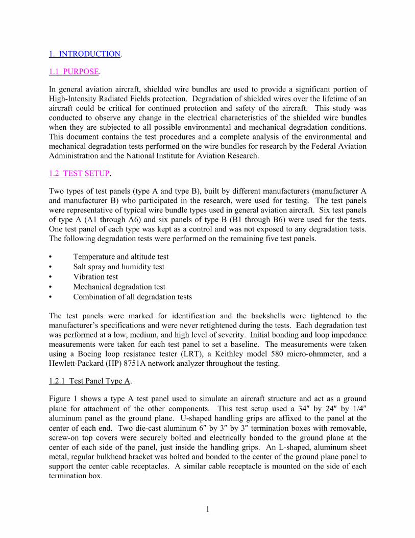
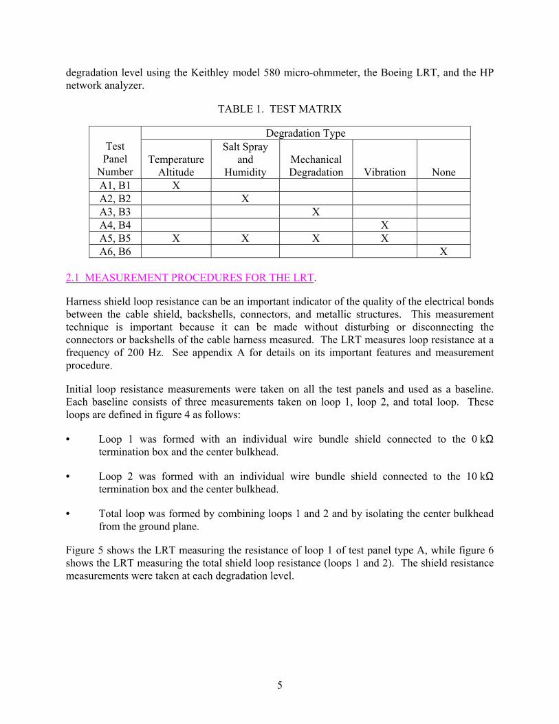
Figure 5 shows the LRT measuring the resistance of loop 1 of test panel type A, while figure 6 shows the LRT measuring the total shield loop resistance (loops 1 and 2). The shield resistance measurements were taken at each degradation level.
5
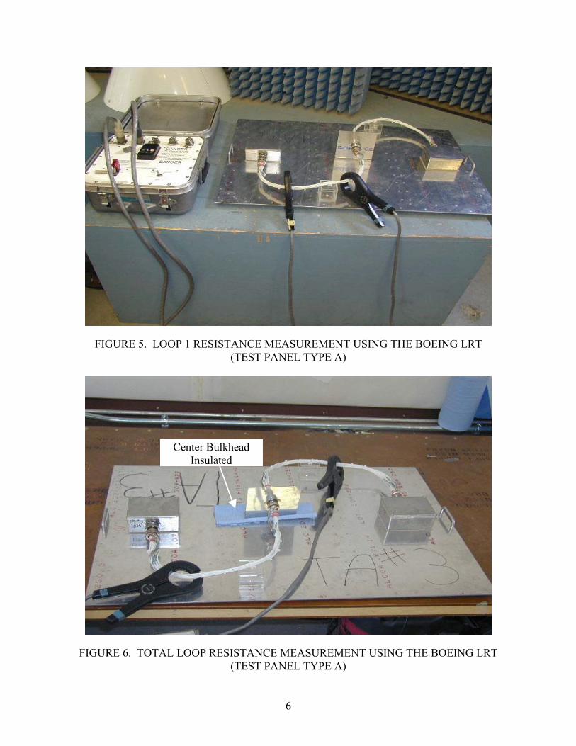
FIGURE 5. LOOP 1 RESISTANCE MEASUREMENT USING THE BOEING LRT (TEST PANEL TYPE A)
Center Bulkhead Insulated
FIGURE 6. TOTAL LOOP RESISTANCE MEASUREMENT USING THE BOEING LRT (TEST PANEL TYPE A)
6
2.2 MEASUREMENT PROCEDURES FOR THE HP 8751A NETWORK ANALYZER.
An HP model 8751A network analyzer was used to measure the loop impedance response over a range of frequencies, 10 Hz to 10 MHz. The impedance measurement at 200 Hz was used to provide a comparison and verification of the Boeing LRT readings.
The measurement setup was made with a Pearson Clamp-On Current Monitor (P/N 3525) and a Pearson Current Injection Probe (P/N CIP9136) clamped around the loop to be monitored. The radio frequency (RF) output from the network analyzer was connected to the Current Injection Probe, which was responsible for current flow induced in the wire bundle through transformer action. Outputs from the Pearson Current Monitor and the Current Injection Probe were connected to the input ports of the network analyzer. The noise factor was subtracted from the real-time measurements, which were used to calculate the loop impedance at that frequency. The following conversion formulae were used to calculate loop impedance.
• The value of voltage (dBm) from the voltage response curve at a specific frequency, on which the impedance of the shield is to be determined, is converted into millivolts. The relation for conversion is:
Voltage (mV) = (Antilog (dBm/20) * 0.224)*1000
where 0.224 V is a reference voltage and is developed when the power is 1 mW across the 50Ω input impedance of the analyzer.
• The value of current (dBm) from the current response curve at the same frequency is converted into milliamperes. The relation for conversion is:
Current (mA) = (Antilog (dBm+60)/20)*0.00447)*1000
where 0.00447 amp is the reference current.
• The division of voltage by current gives the loop impedance at the specified frequency.
See appendix B for more details on its measurement procedure.
Baseline resistance and impedance values were measured for loops 1 and 2 and total loop impedance. These values were compared with the resistance and impedance values after high-level degradation testing.
Figure 7 shows the setup for impedance measurement of loops 1 or 2, and figure 8 shows the measurement setup for the total loop. The center bulkhead bracket was lifted from the ground plane so that the impedance of total loop could be measured.
7
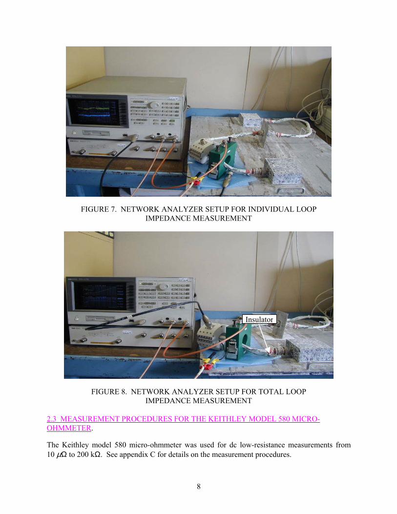
FIGURE 7. NETWORK ANALYZER SETUP FOR INDIVIDUAL LOOP IMPEDANCE MEASUREMENT
Insulator
FIGURE 8. NETWORK ANALYZER SETUP FOR TOTAL LOOP IMPEDANCE MEASUREMENT
2.3 MEASUREMENT PROCEDURES FOR THE KEITHLEY MODEL 580 MICRO-OHMMETER.
The Keithley model 580 micro-ohmmeter was used for dc low-resistance measurements from 10 µΩ to 200 kΩ. See appendix C for details on the measurement procedures.
8
Initial dc joint resistance measurements were taken on each test panel to set a baseline. The baseline was then compared with the readings taken at the end of the degradation test to analyze the extent of degradation. If required, measurements were also taken at any degradation level.
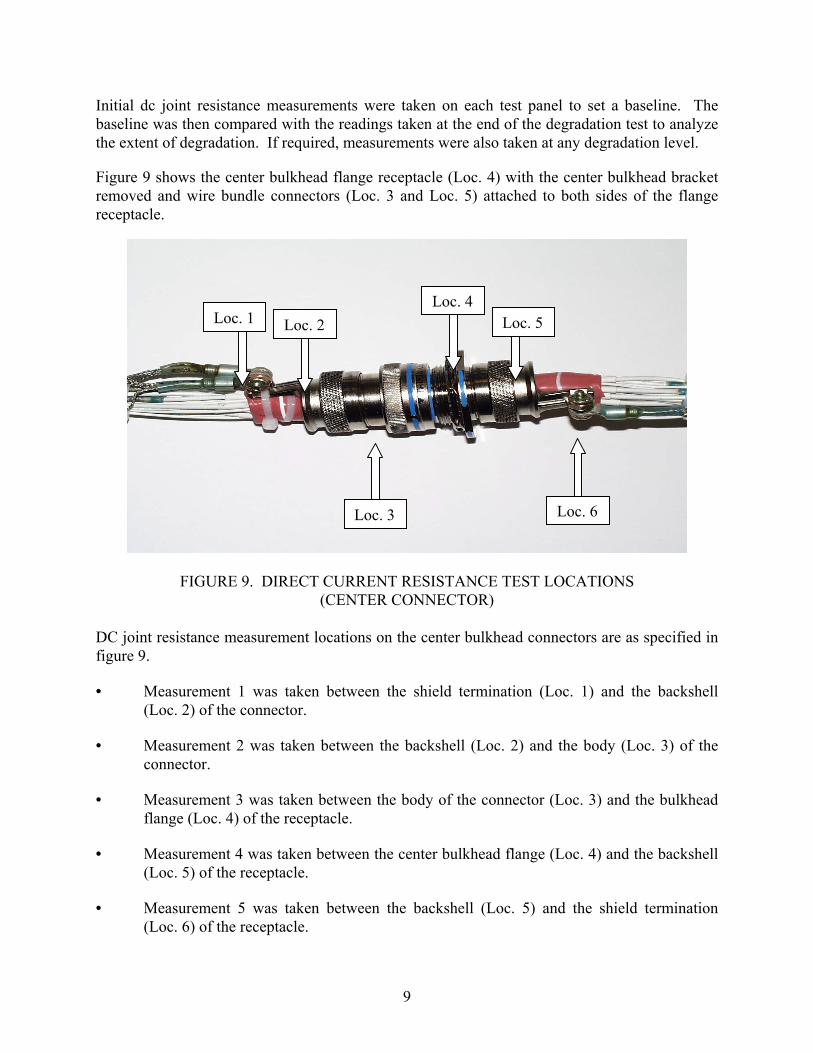
Figure 9 shows the center bulkhead flange receptacle (Loc. 4) with the center bulkhead bracket removed and wire bundle connectors (Loc. 3 and Loc. 5) attached to both sides of the flange receptacle.
Loc. 4Loc. 1 Loc. 5Loc. 2
Loc. 6 Loc. 3
FIGURE 9. DIRECT CURRENT RESISTANCE TEST LOCATIONS
(CENTER CONNECTOR) DC joint resistance measurement locations on the center bulkhead connectors are as specified in figure 9.
• Measurement 1 was taken between the shield termination (Loc. 1) and the backshell (Loc. 2) of the connector.
• Measurement 2 was taken between the backshell (Loc. 2) and the body (Loc. 3) of the connector.
• Measurement 3 was taken between the body of the connector (Loc. 3) and the bulkhead flange (Loc. 4) of the receptacle.
• Measurement 4 was taken between the center bulkhead flange (Loc. 4) and the backshell (Loc. 5) of the receptacle.
• Measurement 5 was taken between the backshell (Loc. 5) and the shield termination (Loc. 6) of the receptacle.
9

The following joint resistance measurements, taken between the shield termination (Loc. 7), the backshell (Loc. 8), and the connector body attached to the termination box, are shown in figure 10.
• Measurement 6 was taken between the shield termination (Loc. 7) and the backshell (Loc. 8) of the connector.
• Measurement 7 was taken between the backshell (Loc. 8) and the body (Loc. 9) of the connector.
• Measurement 8 was taken between the body (Loc. 9) of the connector and the termination box flange receptacle (not shown in figure 10).
Loc. 7Loc. 9
Loc. 8
FIGURE 10. DIRECT CURRENT RESISTANCE TEST LOCATIONS (END CONNECTOR)
If the loop resistance measurements, taken at any severity level using the LRT, deviated more than a set tolerance, shield resistances of the individual wire bundle and the total wire bundle were measured to identify the source of degradation. The following additional measurements were taken with the Keithley model 580 micro-ohmmeter:
• The shield resistance of loop 1 was taken between the shield termination (Loc. 7, figure 10) at the backshell connector (disconnected from the 0 kΩ box) and the shield termination on the backshell (Loc. 6, figure 9) of the center connector that attached to the flange receptacle, which is normally mounted in the center bulkhead bracket.
10

• The shield resistance of loop 2 was taken between the shield termination on the backshell (Loc 7, figure 10) at the end connector (disconnected from the 10 kΩ box) and the shield termination on the backshell (Loc. 1, figure 9) of the center connector attached to the bulkhead.
• The shield resistance of total loop was taken between the shield termination on the backshells of the two end connectors, disconnected from their respective termination boxes, with the two wire bundles connected together, as shown in figure 9.
2.4 VISUAL INSPECTION.
The panels were observed at each level of testing for any visual degradation. Visual inspections were performed to look for the following:
• Signs of chafing, rubbing, or tearing on the wire bundle. • Films, deposits, and evidence of corrosion on the connectors and shields. • Loosening of the connector shields and bulkhead connectors. 2.5 RESISTANCE-INDUCTANCE-RESISTANCE MODELING FOR TEST PANELS.
The loop impedance values for all test panels, as measured by the network analyzer, were modeled with a passive circuit consisting of two resistors and an inductor. The passive circuit was designed with a small resistance in series with an inductor, both in parallel with a relatively large resistor, as shown in figure 11. The series resistance (Rs) was chosen close to the measured loop impedance values at lower frequencies (10 Hz to 1 kHz). The parallel resistor (Rp) was selected to reduce the minimal variation between the experimental impedance values and the model values at higher frequencies. The resistance values of this model (figure 11) was kept at less than 5% over the entire range of frequencies compared to the actual panels.
Zeq = Req + i Xeq Rp
L
Rs
FIGURE 11. CIRCUIT DIAGRAM FOR R-L-R MODELING
11
The loop impedance values, measured at baseline and after degradation testing, were modeled with the resistance-inductance-resistance (R-L-R) circuit. The impedance (Zeq) was calculated as follows: ( ) 22 )( + = XeqReqZeq | |
where 22
2
)( )(
L
L
XRpRsRpXRpRsRsRpReq
++++=
22 )( )(
L
LL
XRpRsRsRpXRpRsRpXXeq
++++
=
and XL = 2π f L The modeling was done to observe the behavior of the shield impedance over a range of frequencies (10 Hz to 10 MHz). An increase in the shield impedance could be a result of a resistive change, an inductive change, or a combination of both. This modeling helped in determining the type of change that caused a loop impedance increase after the test panels were subjected to various degradation tests.
2.6 TEMPERATURE AND ALTITUDE TEST.
2.6.1 Test Procedure.
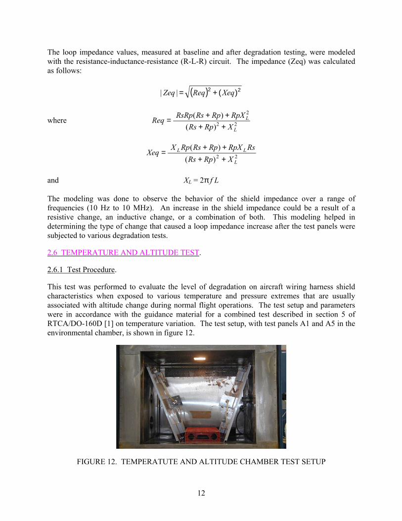
This test was performed to evaluate the level of degradation on aircraft wiring harness shield characteristics when exposed to various temperature and pressure extremes that are usually associated with altitude change during normal flight operations. The test setup and parameters were in accordance with the guidance material for a combined test described in section 5 of RTCA/DO-160D [1] on temperature variation. The test setup, with test panels A1 and A5 in the environmental chamber, is shown in figure 12.
FIGURE 12. TEMPERATUTE AND ALTITUDE CHAMBER TEST SETUP
12
The temperature change rate of category B was chosen from the category definitions in paragraph 5.2 of section 5 of RTCA/DO-160D titled “Temperature Variation.”
The low-, medium-, and high-exposure levels were determined from category definitions in paragraph 4.3 of section 4 of RTCA/DO-160D titled “Equipment Categories.” The levels for this part of the experiment were set at: low - A2; medium - C2; high - F2.
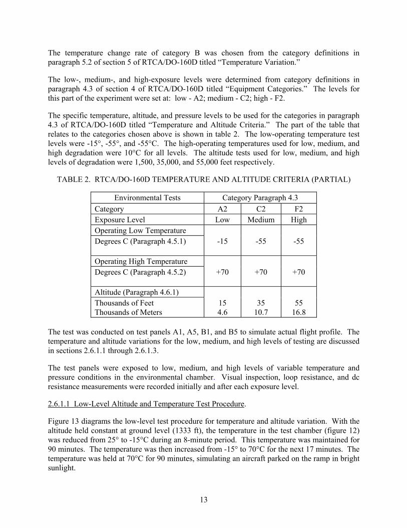
The specific temperature, altitude, and pressure levels to be used for the categories in paragraph 4.3 of RTCA/DO-160D titled “Temperature and Altitude Criteria.” The part of the table that relates to the categories chosen above is shown in table 2. The low-operating temperature test levels were -15°, -55°, and -55°C. The high-operating temperatures used for low, medium, and high degradation were 10°C for all levels. The altitude tests used for low, medium, and high levels of degradation were 1,500, 35,000, and 55,000 feet respectively.
TABLE 2. RTCA/DO-160D TEMPERATURE AND ALTITUDE CRITERIA (PARTIAL)
Environmental Tests Category Paragraph 4.3 Category A2 C2 F2 Exposure Level Low Medium High Operating Low Temperature Degrees C (Paragraph 4.5.1) -15 -55 -55
Operating High Temperature Degrees C (Paragraph 4.5.2) +70 +70 +70
Altitude (Paragraph 4.6.1) Thousands of Feet Thousands of Meters
15 4.6
35 10.7
55 16.8
The test was conducted on test panels A1, A5, B1, and B5 to simulate actual flight profile. The temperature and altitude variations for the low, medium, and high levels of testing are discussed in sections 2.6.1.1 through 2.6.1.3.
The test panels were exposed to low, medium, and high levels of variable temperature and pressure conditions in the environmental chamber. Visual inspection, loop resistance, and dc resistance measurements were recorded initially and after each exposure level.
2.6.1.1 Low-Level Altitude and Temperature Test Procedure.
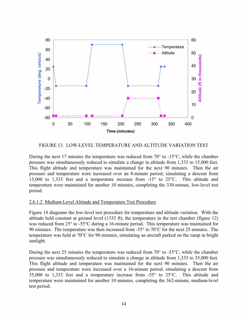
Figure 13 diagrams the low-level test procedure for temperature and altitude variation. With the altitude held constant at ground level (1333 ft), the temperature in the test chamber (figure 12) was reduced from 25° to -15°C during an 8-minute period. This temperature was maintained for 90 minutes. The temperature was then increased from -15° to 70°C for the next 17 minutes. The temperature was held at 70°C for 90 minutes, simulating an aircraft parked on the ramp in bright sunlight.
13
-80
-60
-40
-20
0
20
40
60
80
0 50 100 150 200 250 300 350 400
Time (minutes)
Tem
pera
ture
(deg
. cel
sius
)
0
10
20
30
40
50
60
Alti
tude
(ft i
n th
ousa
nds)
TemperatureAltitude
FIGURE 13. LOW-LEVEL TEMPERATURE AND ALTITUDE VARIATION TEST During the next 17 minutes the temperature was reduced from 70° to -15°C, while the chamber pressure was simultaneously reduced to simulate a change in altitude from 1,333 to 15,000 feet. This flight altitude and temperature was maintained for the next 90 minutes. Then the air pressure and temperature were increased over an 8-minute period, simulating a descent from 15,000 to 1,333 feet and a temperature increase from -15° to 25°C. This altitude and temperature were maintained for another 10 minutes, completing the 330-minute, low-level test period. 2.6.1.2 Medium-Level Altitude and Temperature Test Procedure.
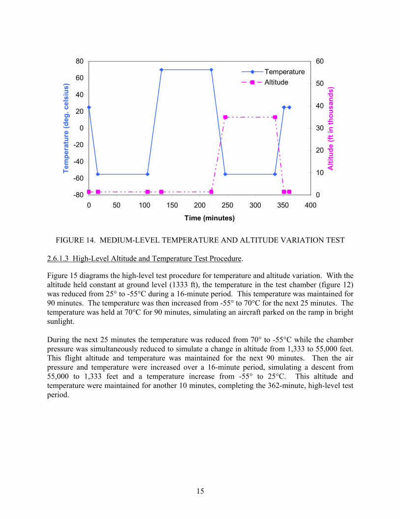
Figure 14 diagrams the low-level test procedure for temperature and altitude variation. With the altitude held constant at ground level (1333 ft), the temperature in the test chamber (figure 12) was reduced from 25° to -55°C during a 16-minute period. This temperature was maintained for 90 minutes. The temperature was then increased from -55° to 70°C for the next 25 minutes. The temperature was held at 70°C for 90 minutes, simulating an aircraft parked on the ramp in bright sunlight. During the next 25 minutes the temperature was reduced from 70° to -55°C, while the chamber pressure was simultaneously reduced to simulate a change in altitude from 1,333 to 35,000 feet. This flight altitude and temperature was maintained for the next 90 minutes. Then the air pressure and temperature were increased over a 16-minute period, simulating a descent from 35,000 to 1,333 feet and a temperature increase from -55° to 25°C. This altitude and temperature were maintained for another 10 minutes, completing the 362-minute, medium-level test period.
14
-80
-60
-40
-20
0
20
40
60
80
0 50 100 150 200 250 300 350 400
Time (minutes)
Tem
pera
ture
(deg
. cel
sius
)
0
10
20
30
40
50
60
Alti
tude
(ft i
n th
ousa
nds)
TemperatureAltitude
FIGURE 14. MEDIUM-LEVEL TEMPERATURE AND ALTITUDE VARIATION TEST
2.6.1.3 High-Level Altitude and Temperature Test Procedure.
Figure 15 diagrams the high-level test procedure for temperature and altitude variation. With the altitude held constant at ground level (1333 ft), the temperature in the test chamber (figure 12) was reduced from 25° to -55°C during a 16-minute period. This temperature was maintained for 90 minutes. The temperature was then increased from -55° to 70°C for the next 25 minutes. The temperature was held at 70°C for 90 minutes, simulating an aircraft parked on the ramp in bright sunlight. During the next 25 minutes the temperature was reduced from 70° to -55°C while the chamber pressure was simultaneously reduced to simulate a change in altitude from 1,333 to 55,000 feet. This flight altitude and temperature was maintained for the next 90 minutes. Then the air pressure and temperature were increased over a 16-minute period, simulating a descent from 55,000 to 1,333 feet and a temperature increase from -55° to 25°C. This altitude and temperature were maintained for another 10 minutes, completing the 362-minute, high-level test period.
15

-80
-60
-40
-20
0
20
40
60
80
0 50 100 150 200 250 300 350 400Time (minutes)
Tem
pera
ture
(deg
. cel
sius
)
0
10
20
30
40
50
60
Alti
tude
(ft i
n th
ousa
nds)
TemperatureAltitude
FIGURE 15. HIGH-LEVEL TEMPERATURE AND ALTITUDE VARIATION TEST
2.6.2 Results.
The results obtained after the temperature and altitude tests, using the network analyzer, are given in table 3 for test panel A1 and in table 4 for test panel B1. The loop impedance, calculated over a range of frequencies (10 Hz to 10 MHz), is tabulated for loops 1 and 2 and total loop. These measurements were recorded at baseline (initial readings) and after the high-level tests (final readings).
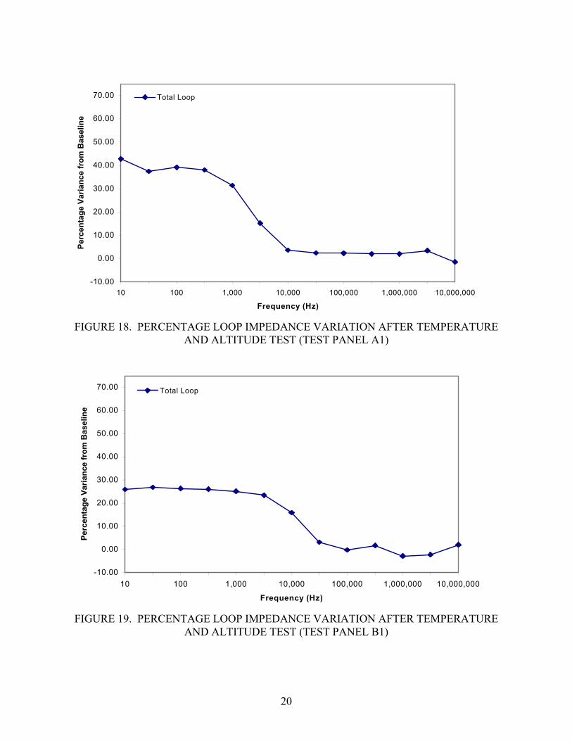
The loop impedance versus frequency (10 Hz to 10 MHz) for test panels A1 and B1 were plotted to analyze the effects of temperature and altitude testing on shield effectiveness. Figures 16 and 17 show the total loop impedance values for the initial and final readings of test panels A1 and B1. For comparison, the corresponding R-L-R model curves are also shown. The values for Rs, inductor (L), and Rp, for both baseline and posttest models, are shown as well. As shown in these graphs, both test panels showed no considerable variation in the loop impedance values between the initial and final readings. A minute change in impedance is seen only in the resistive (for frequencies less than 1 kHz) portion of the graphs. This is also evident from the change in the values of Rs from baseline models to posttest models for both panels. The circuit model Rs increased from 10.75 to 14.9 milliohms for panel A1 and from 61.0 to 77.25 milliohms for panel B1. The values for the other two elements in the model circuit (L and Rp) remained constant. The percentage variation in the total loop impedance values for test panels A1 and B1 is given in figures 18 and 19, respectively. Both test panels A1 and B1 deviated from the baseline only in the resistive portion of the graph (for frequencies less than 1 kHz).
16

TAB
LE 3
. IM
PED
AN
CE
VA
RIA
TIO
NS
OV
ER F
REQ
UEN
CY
RA
NG
E D
UR
ING
TEM
PER
ATU
RE
AN
D A
LTIT
UD
E TE
ST
(TES
T PA
NEL
A1)
Rea
ding
s Fr
eque
ncy
(Hz)
10
30
10
0 20
0 1
K
3 K
10
K
30 K
0.
1 M
0.
3 M
1
M
3 M
10
M
Loop
1 (m
Ω)
5.99
5.76
5.82
5.84
6.53
9.70
25.0
670
.42
228.
3966
921
8663
9616
069
Loop
2 (m
Ω)
6.34
5.
946.
035.
986.
8410
.43
27.2
978
.18
254.
3875
224
8971
9020
143
Initi
al
Tota
l Loo
p (m
Ω)
11.1
5
10
.70
10.6
310
.75
12.1
819
.65
53.3
315
2.42
494.
3014
7648
3213
804
3209
6
Loop
1 (m
Ω)
8.47
8.
228.
158.
288.
7611
.66
27.5
173
.35
233.
9368
822
5665
5516
122
Loop
2 (m
Ω)
8.51
8.
268.
298.
288.
912
.07
28.2
777
.85
252.
1174
624
5471
5118
725
Fina
l
Tota
l Loo
p (m
Ω)
15.9
2
14
.71
14.7
914
.84
16.0
122
.65
55.2
915
6.19
506.
0515
0749
3014
277
3855
0
Not
e: M
easu
rem
ents
wer
e m
ade
with
an
HP
netw
ork
anal
yzer
.
17
TAB
LE 4
. IM
PED
AN
CE
VA
RIA
TIO
NS
OV
ER F
REQ
UEN
CY
RA
NG
E D
UR
ING
TEM
PER
ATU
RE
AN
D A
LTIT
UD
E TE
ST
(TES
T PA
NEL
B1)
Rea
ding
s Fr
eque
ncy
(Hz)
10
30
10
0 20
0 1
K
3 K
10
K
30 K
0.
1 M
0.
3 M
1
M
3 M
10
M
Loop
1 (m
Ω)
14.8
6
29.7
429
.46
29.3
529
.52
30.4
738
.39
76.8
423
2.45
678.
1722
0564
0615
874
Loop
2 (m
Ω)
32.9
0
30.0
429
.85
29.8
029
.89
31.0
839
.70
80.7
924
3.02
704.
9222
6866
8618
664
Initi
al
Tota
l Loo
p (m
Ω)
60.5
0
61
.44
61.0
561
.02
61.4
563
.39
80.2
516
5.09
499.
6714
1947
5313
610
3037
3
Loop
1 (m
Ω)
35.0
8
34.3
834
.21
34.0
734
.22
34.9
342
.30
79.0
623
2.53
482.
5422
1465
3717
284
Loop
2 (m
Ω)
37.7
9
38.5
738
.34
38.2
038
.33
39.1
547
.54
90.3
526
2.05
754.
9824
6171
7120
194
Fina
l
Tota
l Loo
p (m
Ω)
76.1
8
77
.95
77.1
476
.92
76.9
078
.24
93.0
017
0.31
498.
4714
4346
1913
305
3098
2
Not
e: M
easu
rem
ents
wer
e m
ade
with
an
HP
netw
ork
anal
yzer
.

110100
1000
1000
0
1000
00
110
100
1000
1000
010
0000
1000
000
1000
0000
Freq
uenc
y (H
z)
Impedance (milliohms)
Base
line
Base
line
Mod
el
Post
Tes
tP
ost T
est M
odel
Bas
elin
e
Mod
el
R
s
=
10.7
5mΩ
L
=
0.81
mH
Rp
=
53
Ω
Post
Tes
t M
odel
Rs
=
14.9
mΩ
L
= 0.
81m
H
Rp
=
53Ω
18
FI
GU
RE
16.
TOTA
L LO
OP
IMPE
DA
NC
E C
HA
RA
CTE
RIS
TIC
S B
EFO
RE
AN
D A
FTER
TEM
PER
ATU
RE
AN
D
ALT
ITU
DE
TEST
(TES
T PA
NEL
A1)

10100
1000
1000
0
1000
00
1010
010
0010
000
1000
0010
0000
010
0000
00
Freq
uenc
y (H
z)
Impedance (milliohms)
Base
line
Base
line
Mod
el
Post
Tes
tP
ost T
est M
odel
Bas
elin
e
Mod
el
Rs
=
61m
Ω
L
=
0.78
mH
Rp
=
40Ω
19
Post
Tes
t M
odel
Rs
=
77.2
5mΩ
L
= 0.
78m
H
Rp
=
40Ω
FI
GU
RE
17.
TOTA
L LO
OP
IMPE
DA
NC
E C
HA
RA
CTE
RIS
TIC
S B
EFO
RE
AN
D A
FTER
TEM
PER
ATU
RE
AN
D
ALT
ITU
DE
TEST
(TES
T PA
NEL
B1)
-10.00
0.00
10.00
20.00
30.00
40.00
50.00
60.00
70.00
10 100 1,000 10,000 100,000 1,000,000 10,000,000
Frequency (Hz)
Perc
enta
ge V
aria
nce
from
Bas
elin
e
Total Loop
FIGURE 18. PERCENTAGE LOOP IMPEDANCE VARIATION AFTER TEMPERATURE
AND ALTITUDE TEST (TEST PANEL A1)
-10.00
0.00
10.00
20.00
30.00
40.00
50.00
60.00
70.00
10 100 1,000 10,000 100,000 1,000,000 10,000,000
Frequency (Hz)
Perc
enta
ge V
aria
nce
from
Bas
elin
e
Total Loop
FIGURE 19. PERCENTAGE LOOP IMPEDANCE VARIATION AFTER TEMPERATURE
AND ALTITUDE TEST (TEST PANEL B1)
20

Tables 5 and 6 show the loop resistance values, as measured by the Boeing LRT after each testing level, to analyze the shield degradation for test panels A1 and B1, respectively. These tables list the loop resistance values for loops 1 and 2 and total loop at different levels of temperature and altitude testing. The observations made during the test for any visual degradation are also tabulated. A gradual increase in the resistance values was noticed as the severity level changed from low to high, but the increase was within tolerance limits. Neither of the test panels showed signs of visual degradation at any level of temperature and altitude testing. The data for total loop resistance in these tables is graphically represented in figures 20 and 21.
TABLE 5. BOEING LRT READINGS FOR TEMPERATURE AND ALTITUDE TEST (TEST PANEL A1)
Test Level Loop 1 (mΩ)
Loop 2 (mΩ)
Total Loop (mΩ)
R-L-R Model Total Loop Rs (mΩ)
Visual Degradation
Baseline 5.82 5.98 10.26 10.75 None Low 6.55 6.95 11.88 None Medium 7.01 7.59 12.59 None High 7.82 8.98 14.38 14.9 None
TABLE 6. BOEING LRT READINGS FOR TEMPERATURE AND ALTITUDE TEST
(TEST PANEL B1)
Test Level Loop 1 (mΩ)
Loop 2 (mΩ)
Total Loop (mΩ)
R-L-R Model Total Loop Rs (mΩ)
Visual Degradation
Baseline 30.41 30.84 60.71 61 None Low 32.68 36.02 56.48 None Medium 31.40 33.03 65.59 None High 38.54 40.74 70.68 77.25 None To verify that the increase in loop resistance was not due to the changes in the joint resistances of different electrical contacts of wire harnesses (figures 9 and 10), the dc measurements were recorded using a Keithley model 580 micro-ohmmeter at each degradation level for test panel A1 (table 7). A very small change was observed between baseline resistance values and high-level resistance values of the electrical contacts. Therefore, any increase found in the loop resistance value was assumed not to be due to change in contact resistance.
21

0
5
10
15
20
25
30
Baseline Low Medium High
Test Level
Res
ista
nce
(mill
iohm
s)
Total Loop
FIGURE 20. TOTAL LOOP RESISTANCE VALUES FOR TEMPERATURE AND
ALTITUDE TEST USING THE BOEING LRT (TEST PANEL A1)
0
10
20
30
40
50
60
70
80
90
100
Baseline Low Medium High
Test Level
Res
ista
nce
(mill
eohm
s)
Total Loop
FIGURE 21. TOTAL LOOP RESISTANCE VALUES FOR TEMPERATURE AND
ALTITUDE TEST USING THE BOEING LRT (TEST PANEL B1)
22

TABLE 7. DIRECT CURRENT MEASUREMENTS FOR TEMPERATURE AND ALTITUDE TEST (TEST PANEL A1)
Test Level
DC Measurements Baselin
e Low Medium High ∆
Measurement 1 (mΩ) 0.16 0.2 0.22 0.06 Measurement 2 (mΩ) 0.1 0.1 0.1 0.0 Measurement 3 (mΩ) 0.38 0.38 0.39 0.01 Measurement 4 (mΩ) 0.27 0.24 0.25 -0.02 Measurement 5 (mΩ) 0.16 0.24 0.25 0.09
Connector 1 0.23 0.27 0.31 0.08 Measurement 6 (mΩ)
Connector 2 0.11 0.12 0.11 0.0 Connector 1 0.16 0.18 0.21 0.05
Measurement 7 (mΩ) Connector 2 0.32 0.32 0.3 -0.02 Connector 1 0.28 0.32 0.34 0.06
Measurement 8 (mΩ) Connector 2 0.34 0.45 0.45 0.09
Shield Resistance 1 (mΩ) 3.0 2.9 -0.01 Shield Resistance 2 (mΩ) 3.3 3.32 0.02 Total Shield Resistance (mΩ) 7.29 7.76 0.47
Note: Explanation of all the measurements is given in section 2. Connector 1 is the end connector connected to 0 kΩ termination box.
Connector 2 is the end connector connected to 10 kΩ termination box. ∆= High-baseline measurements (mΩ).
2.6.3 Observations (Temperature and Altitude Tests).
The following observations were based upon analysis of the recorded experimental data and visual inspections.
• There was a slight increase in the resistive portion of shield loop impedance measurements, over the swept frequency (10 Hz to 10 MHz), from initial to final readings.
• Shield loop resistance measurements, using the LRT, were within the acceptable tolerances at all degradation levels of temperature and altitude testing.
• No visual degradation was observed during the entire temperature and altitude test.
23
2.7 SALT SPRAY AND HUMIDITY TEST.
2.7.1 Test Procedure.
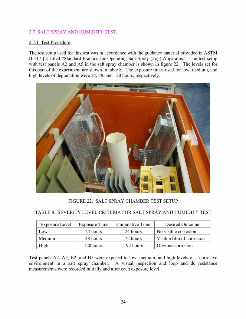
The test setup used for this test was in accordance with the guidance material provided in ASTM B 117 [2] titled “Standard Practice for Operating Salt Spray (Fog) Apparatus.” The test setup with test panels A2 and A5 in the salt spray chamber is shown in figure 22. The levels set for this part of the experiment are shown in table 8. The exposure times used for low, medium, and high levels of degradation were 24, 48, and 120 hours, respectively.
FIGURE 22. SALT SPRAY CHAMBER TEST SETUP
TABLE 8. SEVERITY LEVEL CRITERIA FOR SALT SPRAY AND HUMIDITY TEST
Exposure Level Exposure Time Cumulative Time Desired Outcome Low 24 hours 24 hours No visible corrosion Medium 48 hours 72 hours Visible film of corrosion High 120 hours 192 hours Obvious corrosion
Test panels A2, A5, B2, and B5 were exposed to low, medium, and high levels of a corrosive environment in a salt spray chamber. A visual inspection and loop and dc resistance measurements were recorded initially and after each exposure level.
24
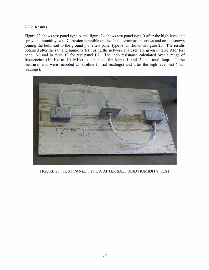
2.7.2 Results.
Figure 23 shows test panel type A and figure 24 shows test panel type B after the high-level salt spray and humidity test. Corrosion is visible on the shield termination screws and on the screws joining the bulkhead to the ground plane test panel type A, as shown in figure 25. The results obtained after the salt and humidity test, using the network analyzer, are given in table 9 for test panel A2 and in table 10 for test panel B2. The loop resistance calculated over a range of frequencies (10 Hz to 10 MHz) is tabulated for loops 1 and 2 and total loop. These measurements were recorded at baseline (initial readings) and after the high-level test (final readings).
FIGURE 23. TEST PANEL TYPE A AFTER SALT AND HUMIDITY TEST
25

FIGURE 24. TEST PANEL TYPE B AFTER SALT AND HUMIDITY TEST
FIGURE 25. VISIBLE CORROSION AFTER SALT AND HUMIDITY TEST
26

TAB
LE 9
. IM
PED
AN
CE
VA
RIA
TIO
NS
OV
ER F
REQ
UEN
CY
RA
NG
E D
UR
ING
SA
LT A
ND
HU
MID
ITY
TES
T (T
EST
PAN
EL A
2)
Rea
ding
s Fr
eque
ncy
(Hz)
10
30
10
0 20
0 1
K
3 K
10
K
30 K
0.
1 M
0.
3 M
1
M
3 M
10
M
Loop
1 (m
Ω)
5.63
5.
215.
295.
246.
069.
5525
.46
72.8
123
8.17
707
2288
6704
1686
3Lo
op 2
(mΩ
) 5.
33
5.
195.
245.
345.
989.
1624
.40
69.3
822
5.62
664
2181
6174
1504
3In
itial
To
tal L
oop
(mΩ
) 10
.69
9.
639.
689.
7611
.26
18.7
852
.27
150.
0348
9.20
1448
4765
1389
434
543
Loop
1 (m
Ω)
11.8
4
13.2
111
.79
11.8
012
.97
18.9
648
.24
121.
3626
8.59
706
2312
6663
1687
2Lo
op 2
(mΩ
) 11
.92
12
.00
11.8
212
.06
13.1
119
.40
49.2
512
0.79
256.
7667
521
9564
1117
081
Fina
l To
tal L
oop
(mΩ
) 12
.76
12.2
512
.19
12.2
113
.42
19.8
051
.42
146.
9447
9.00
1423
4717
1375
036
081
TA
BLE
10.
IM
PED
AN
CE
VA
RIA
TIO
NS
OV
ER F
REQ
UEN
CY
RA
NG
E D
UR
ING
SA
LT A
ND
HU
MID
ITY
TES
T (T
EST
PAN
EL B
2)
27
Rea
ding
s Fr
eque
ncy
(Hz)
10
30
10
0 20
0 1
K
3 K
10
K
30 K
0.
1 M
0.
3 M
1
M
3 M
10
M
Loop
1 (m
Ω)
20.9
920
.22
20.2
120
.24
20.4
321
.47
30.4
7
69
.17
216.
2463
3.34
2058
6005
1436
4Lo
op 2
(mΩ
) 25
.54
24.4
924
.21
24.0
476
.67
25.4
835
.70
80.4
025
2.43
737.
6323
7968
5518
664
Initi
al
Tota
l Loo
p (m
Ω)
40.6
140
.21
39.3
739
.36
40.0
543
.18
66.7
3
162.
4751
7.83
1525
4945
1389
327
939
Loop
1 (m
Ω)
23.0
422
.18
22.1
422
.08
22.2
623
.26
32.7
8
73
.91
230.
5167
1.64
2187
6425
1599
4Lo
op 2
(mΩ
) 33
.27
33.3
233
.10
32.9
933
.19
34.1
441
.91
82.1
024
6.37
720.
1723
5268
1218
810
Fina
l To
tal L
oop
(mΩ
) 40
.39
38.8
439
.03
39.0
539
.65
42.5
765
.43
15
7.12
498.
1214
6547
5213
809
3262
8
The loop impedance versus frequency (10 Hz to 10 MHz) for test panels A2 and B2 were plotted to analyze the effects of salt spray and humidity tests on shield effectiveness. Figures 26 and 27 show the total loop resistance values for the initial and final readings of test panels A2 and B2, respectively. For comparison, the corresponding R-L-R model curves are also shown. The values for Rs, L, and Rp, for both baseline and posttest models, are shown as well. A small change in impedance was seen in the resistive (for frequencies less than 1 kHz) portion of the graph of test panel A2. This is evident from the change in the value of Rs from the baseline model to the posttest model. The values for the other two elements in the model circuit remained constant. For test panel B2, there was a small increase in the parallel resistance of the R-L-R model while the other two parameters remained the same. The percentage variation in the total loop resistance values for test panels A2 and B2 is given in figures 28 and 29, respectively. Test panel A2 showed no deviation from the baseline in the resistive (for frequencies less than 3 kHz) portion of the graph, whereas an increase of 5% was observed in the reactive portion. Test panel B2 showed no change from the baseline in the resistive (for frequencies less than 3 kHz) portion, but there was a 15% increase in the reactive portion at 10 MHz.
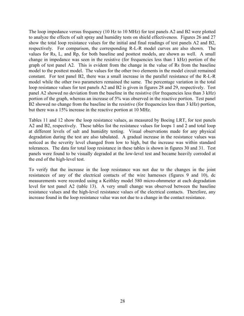
Tables 11 and 12 show the loop resistance values, as measured by Boeing LRT, for test panels A2 and B2, respectively. These tables list the resistance values for loops 1 and 2 and total loop at different levels of salt and humidity testing. Visual observations made for any physical degradation during the test are also tabulated. A gradual increase in the resistance values was noticed as the severity level changed from low to high, but the increase was within standard tolerances. The data for total loop resistance in these tables is shown in figures 30 and 31. Test panels were found to be visually degraded at the low-level test and became heavily corroded at the end of the high-level test.
To verify that the increase in the loop resistance was not due to the changes in the joint resistances of any of the electrical contacts of the wire harnesses (figures 9 and 10), dc measurements were recorded using a Keithley model 580 micro-ohmmeter at each degradation level for test panel A2 (table 13). A very small change was observed between the baseline resistance values and the high-level resistance values of the electrical contacts. Therefore, any increase found in the loop resistance value was not due to a change in the contact resistance.
28

110100
1000
1000
0
1000
00
110
100
1000
1000
010
0000
1000
000
1000
0000
Freq
uenc
y (H
z)
Impedance (milliohms)
Base
line
Base
line
Mod
elPo
st T
est
Pos
t Tes
t Mod
el
Bas
elin
e M
odel
Rs
=
9.75
mΩ
L
=
0.8m
H
Rp
=
46Ω
29
Post
Tes
t Mod
el
Rs
=
12
.2m
Ω
L
=
0.
8mH
Rp
=
46
Ω
FI
GU
RE
26.
TOTA
L LO
OP
IMPE
DA
NC
E C
HA
RA
CTE
RIS
TIC
S B
EFO
RE
AN
D A
FTER
SA
LT A
ND
HU
MID
ITY
TES
T (T
EST
PAN
EL A
2)

110100
1000
1000
0
1000
00
110
100
1000
1000
010
0000
1000
000
1000
0000
Freq
uenc
y (H
z)
Impedance (milliohms)
Base
line
Base
line
Mod
elPo
st te
stP
ost T
est M
odel
Bas
elin
e M
odel
Rs
=
40
mΩ
L
=
0.8m
H
Rp
=
34Ω
30
Post
Tes
t Mod
el
R
s
=
40m
Ω
L
=
0.
8mH
Rp
=41
Ω
FI
GU
RE
27.
TOTA
L LO
OP
IMPE
DA
NC
E C
HA
RA
CTE
RIS
TIC
S B
EFO
RE
AN
D A
FTER
SA
LT A
ND
HU
MID
ITY
TES
T (T
EST
PAN
EL B
2)

-10.00
0.00
10.00
20.00
30.00
40.00
50.00
60.00
70.00
10 100 1,000 10,000 100,000 1,000,000 10,000,000
Frequency (Hz)
Perc
enta
ge V
aria
tion
from
Bas
elin
e
Total Loop
FIGURE 28. PERCENTAGE LOOP IMPEDANCE VARIATION AFTER SALT AND
HUMIDITY TEST (TEST PANEL A2)
-10.00
-5.00
0.00
5.00
10.00
15.00
20.00
25.00
30.00
35.00
10 100 1,000 10,000 100,000 1,000,000 10,000,000
Frequency (Hz)
Perc
enta
ge V
aria
tion
from
Bas
elin
e Total Loop
FIGURE 29. PERCENTAGE LOOP IMPEDANCE VARIATION AFTER SALT AND
HUMIDITY TEST (TEST PANEL B2)
31
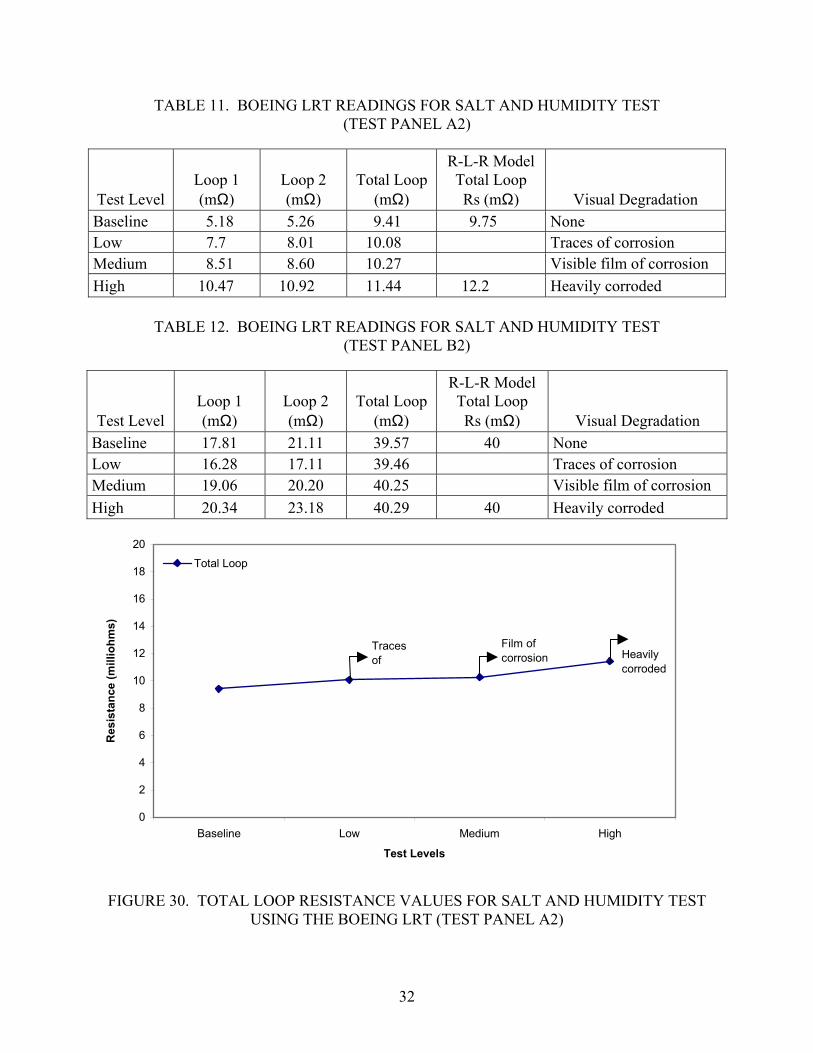
TABLE 11. BOEING LRT READINGS FOR SALT AND HUMIDITY TEST (TEST PANEL A2)
Test Level Loop 1 (mΩ)
Loop 2 (mΩ)
Total Loop(mΩ)
R-L-R ModelTotal Loop Rs (mΩ) Visual Degradation
Baseline 5.18 5.26 9.41 9.75 None Low 7.7 8.01 10.08 Traces of corrosion Medium 8.51 8.60 10.27 Visible film of corrosion High 10.47 10.92 11.44 12.2 Heavily corroded
TABLE 12. BOEING LRT READINGS FOR SALT AND HUMIDITY TEST (TEST PANEL B2)
Test Level Loop 1 (mΩ)
Loop 2 (mΩ)
Total Loop (mΩ)
R-L-R ModelTotal Loop Rs (mΩ) Visual Degradation
Baseline 17.81 21.11 39.57 40 None Low 16.28 17.11 39.46 Traces of corrosion Medium 19.06 20.20 40.25 Visible film of corrosion High 20.34 23.18 40.29 40 Heavily corroded
0
2
4
6
8
10
12
14
16
18
20
Baseline Low Medium High
Test Levels
Res
ista
nce
(mill
iohm
s)
Total Loop
Traces of
Film of corrosion Heavily
corroded
FIGURE 30. TOTAL LOOP RESISTANCE VALUES FOR SALT AND HUMIDITY TEST USING THE BOEING LRT (TEST PANEL A2)
32

30
32
34
36
38
40
42
44
46
48
Baseline Low Medium High
Test Level
Res
ista
nce
(mill
iohm
s)
Total Loop
Traces of corrosion
Film of corrosion Heavily
corroded
FIGURE 31. TOTAL LOOP RESISTANCE VALUES FOR SALT AND HUMIDITY TEST USING THE BOEING LRT (TEST PANEL B2)
TABLE 13. DIRECT CURRENT MEASUREMENTS FOR SALT AND HUMIDITY TEST
(TEST PANEL A2)
Test Level DC Measurements Baseline Low Medium High ∆
Measurement 1 (mΩ) 0.29 0.3 0.31 0.02 Measurement 2 (mΩ) 0.2 0.2 0.21 0.01 Measurement 3 (mΩ) 0.16 0.14 0.14 -0.02 Measurement 4 (mΩ) 0.37 0.27 0.26 -0.11 Measurement 5 (mΩ) 0.14 0.13 0.13 -0.01 Measurement 6 (mΩ) Connector 1 0.2 0.2 0.22 0.02 Connector 2 0.15 0.16 0.17 0.02 Measurement 7 (mΩ) Connector 1 0.15 0.18 0.25 0.10 Connector 2 0.19 0.2 0.22 0.03 Measurement 8 (mΩ) Connector 1 0.24 0.26 0.27 0.03 Connector 2 0.32 0.36 0.38 0.06 Shield Resistance 1 (mΩ) 3.19 3.2 3.2 0.01 Shield Resistance 2 (mΩ) 3.22 3.23 3.22 0.0 Total Shield Resistance (mΩ) 7.26 7.29 7.33 0.07
Note: Explanation of all the measurements is given in section 2. Connector 1 is the end connector connected to the 0 kΩ termination box.
Connector 2 is the end connector connected to the 10 kΩ termination box. ∆= High-baseline measurements (mΩ).
33

2.7.3 Observations (Salt Spray and Humidity Tests).
The following observations were based upon analysis of the experimental data and visual inspections:
• No chafing, rubbing, or tearing occurred at any level of testing.
• Marked signs of corrosion started at the low-level degradation test and were obvious at the high-level degradation test. The whole ground plane and center bulkhead, except the connectors, were rusted.
• The exposed part of the harness shield was brittle and corroded at the end of testing.
• Shield loop impedance and dc measurements were surprisingly still within acceptable tolerance limits after all degradation levels.
• Visual degradation was observed before any significant increase in loop impedance was detected.
2.8 VIBRATION TEST.
2.8.1 Test Procedure.
Test Panels A4, A5, B4, and B5 were subjected to vibration tests according to Robust Random Vibration Curve D1 in reference 3. The vibration test was performed on the test panels to simulate the vibration conditions in an aircraft. Three identifiers specify these conditions: (1) aircraft type, (2) category, and (3) aircraft zone location. The worst possible combination was chosen from section 8.2.2, “Category and Test Curve/Level Selection,” from RTCA/DO-160D and is given in table 14.
TABLE 14. CATEGORY AND TEST CURVE AND LEVEL SELECTION (PARTIAL)
Category Aircraft Type Vibration Test R or R2 It demonstrates performance at higher vibration levels and after long-term vibration exposure
Fixed wing Robust Random Vibration Random at 30 min performance level, 3 hr endurance level and 30 min performance level (repeated in all 3 axis)
Because the vibration table was small, the entire test panel type A could not be mounted on the vibration table. Therefore, only the center bulkhead and connectors were subjected to vibration. The center bulkhead was removed from the ground plane and then attached to the mounting plate of the vibration table with specially made fixtures.
34
Three test series were run on each test panel. Each of the three orthogonal axes (x, y, and z), corresponding to aircraft coordinates: x = fuselage station, y = buttock line, and z = water line, were subjected to 4 hours of vibration.
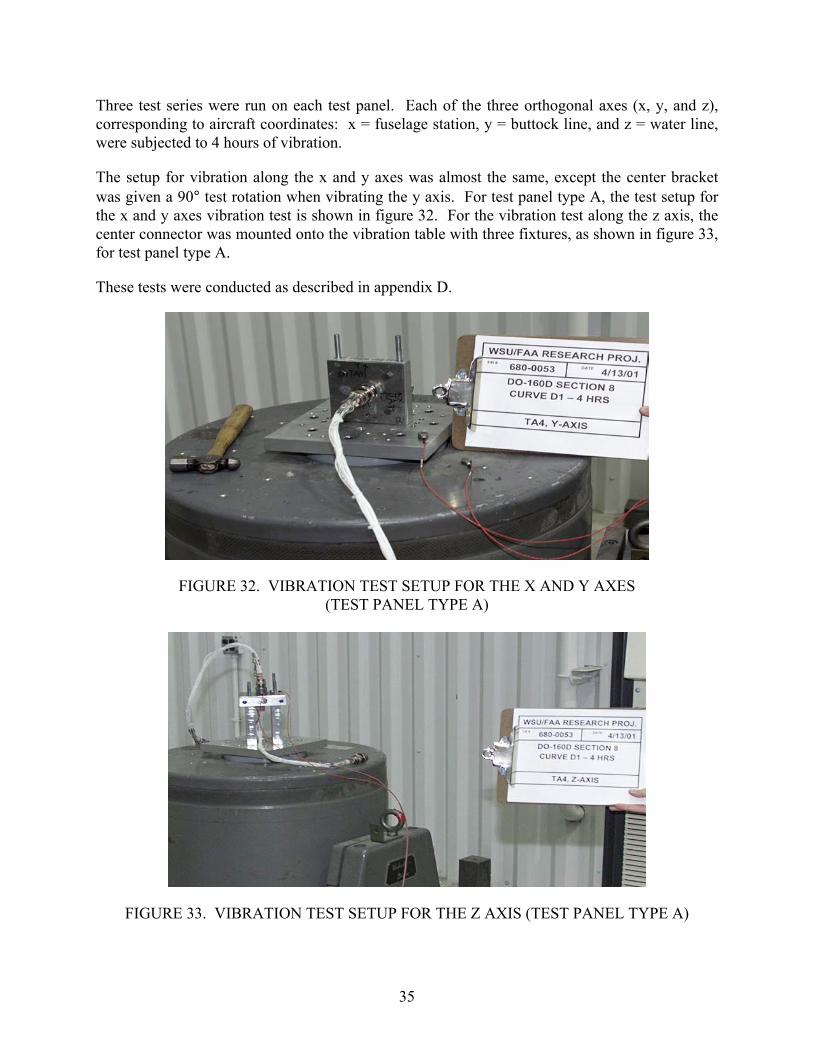
The setup for vibration along the x and y axes was almost the same, except the center bracket was given a 90° test rotation when vibrating the y axis. For test panel type A, the test setup for the x and y axes vibration test is shown in figure 32. For the vibration test along the z axis, the center connector was mounted onto the vibration table with three fixtures, as shown in figure 33, for test panel type A.
These tests were conducted as described in appendix D.
FIGURE 32. VIBRATION TEST SETUP FOR THE X AND Y AXES (TEST PANEL TYPE A)
FIGURE 33. VIBRATION TEST SETUP FOR THE Z AXIS (TEST PANEL TYPE A)
35
Visual inspection, loop resistance test, and dc resistance measurements were recorded before and after each axis vibration test.
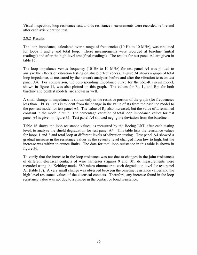
2.8.2 Results.
The loop impedance, calculated over a range of frequencies (10 Hz to 10 MHz), was tabulated for loops 1 and 2 and total loop. These measurements were recorded at baseline (initial readings) and after the high-level test (final readings). The results for test panel A4 are given in table 15.
The loop impedance versus frequency (10 Hz to 10 MHz) for test panel A4 was plotted to analyze the effects of vibration testing on shield effectiveness. Figure 34 shows a graph of total loop impedance, as measured by the network analyzer, before and after the vibration tests on test panel A4. For comparison, the corresponding impedance curve for the R-L-R circuit model, shown in figure 11, was also plotted on this graph. The values for Rs, L, and Rp, for both baseline and posttest models, are shown as well.
A small change in impedance is shown only in the resistive portion of the graph (for frequencies less than 1 kHz). This is evident from the change in the value of Rs from the baseline model to the posttest model for test panel A4. The value of Rp also increased, but the value of L remained constant in the model circuit. The percentage variation of total loop impedance values for test panel A4 is given in figure 35. Test panel A4 showed negligible deviation from the baseline.
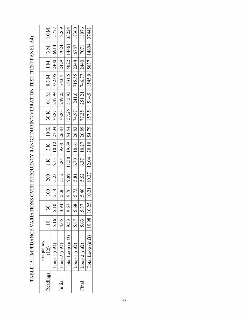
Table 16 shows the loop resistance values, as measured by the Boeing LRT, after each testing level, to analyze the shield degradation for test panel A4. This table lists the resistance values for loops 1 and 2 and total loop at different levels of vibration testing. Test panel A4 showed a gradual increase in the resistance values as the severity level changed from low to high, but the increase was within tolerance limits. The data for total loop resistance in this table is shown in figure 36.
To verify that the increase in the loop resistance was not due to changes in the joint resistances of different electrical contacts of wire harnesses (figures 9 and 10), dc measurements were recorded using the Keithley model 580 micro-ohmmeter at each degradation level for test panel A1 (table 17). A very small change was observed between the baseline resistance values and the high-level resistance values of the electrical contacts. Therefore, any increase found in the loop resistance value was not due to a change in the contact or bond resistance.
36
TAB
LE 1
5. I
MPE
DA
NC
E V
AR
IATI
ON
S O
VER
FR
EQU
ENC
Y R
AN
GE
DU
RIN
G V
IBR
ATI
ON
TES
T (T
EST
PAN
EL A
4)
Rea
ding
s Fr
eque
ncy
(Hz)
10
30
10
0 20
0 1
K
3 K
10
K
30 K
0.
1 M
0.
3 M
1
M
3 M
10
M
Loop
1 (m
Ω)
5.16
5.10
5.14
5.23
6.15
10.1
227
.04
76.8
724
7.94
732.
0524
0069
1415
777
Loop
2 (m
Ω)
4.65
4.94
5.06
5.12
5.84
9.68
26.8
176
.83
249.
2574
3.4
2429
7024
1826
9In
itial
To
tal L
oop
(mΩ
) 9.
53
9.67
9.76
9.89
11.5
819
.69
54.5
415
7.25
515.
9315
31.5
5022
1446
133
224
Loop
1 (m
Ω)
5.87
5.
685.
735.
816.
7010
.61
26.8
374
.97
241.
671
5.55
2344
6787
1736
0Lo
op 2
(mΩ
) 5.
63
5.
375.
465.
526.
3710
.27
26.8
977
.25
251.
2174
6.77
2440
7071
1807
6Fi
nal
Tota
l Loo
p (m
Ω)
10.9
810
.25
10.2
110
.27
12.0
420
.10
54.7
9
15
7.5
514.
915
45.9
5037
1460
437
441
37

110100
1000
1000
0
1000
00
110
100
1000
1000
010
0000
1000
000
1000
0000
Freq
uenc
y (H
z)
Impedance (milliohms)
Base
line
Base
line
Mod
el
Post
Tes
tPo
st T
est M
odel
Bas
elin
e M
odel
Rs
= 9.
8mΩ
L
=
0.
845m
H
Rp
= 43
Ω
38
Post
Tes
t M
odel
Rs
=
10.4
mΩ
L
=
0.84
5mH
Rp
=
48Ω
FIG
UR
E 34
. TO
TAL
LOO
P IM
PED
AN
CE
CH
AR
AC
TER
ISTI
CS
BEF
OR
E A
ND
AFT
ER V
IBR
ATI
ON
TES
T (T
EST
PAN
EL A
4)

-10.00
-5.00
0.00
5.00
10.00
15.00
20.00
25.00
30.00
35.00
40.00
10 100 1,000 10,000 100,000 1,000,000 10,000,000
Frequency (Hz)
Perc
enta
ge V
aria
ce fr
om B
asel
ine
Total Loop
FIGURE 35. PERCENTAGE LOOP IMPEDANCE VARIATION AFTER VIBRATION TEST
(TEST PANEL A4)
TABLE 16. RESISTANCE VALUES FOR VIBRATION TEST USING THE BOEING LRT (TEST PANEL A4)
Test Level Loop 1 (mΩ)
Loop 2 (mΩ)
Total Loop (mΩ)
R-L-R Model Total Loop Rs (mΩ)
Visual Degradation
Baseline 5.23 5.0 9.48 9.8 None Low 5.60 5.34 9.69 None Medium 5.5 5.35 9.76 None High 5.52 5.41 9.9 10.9 None
39
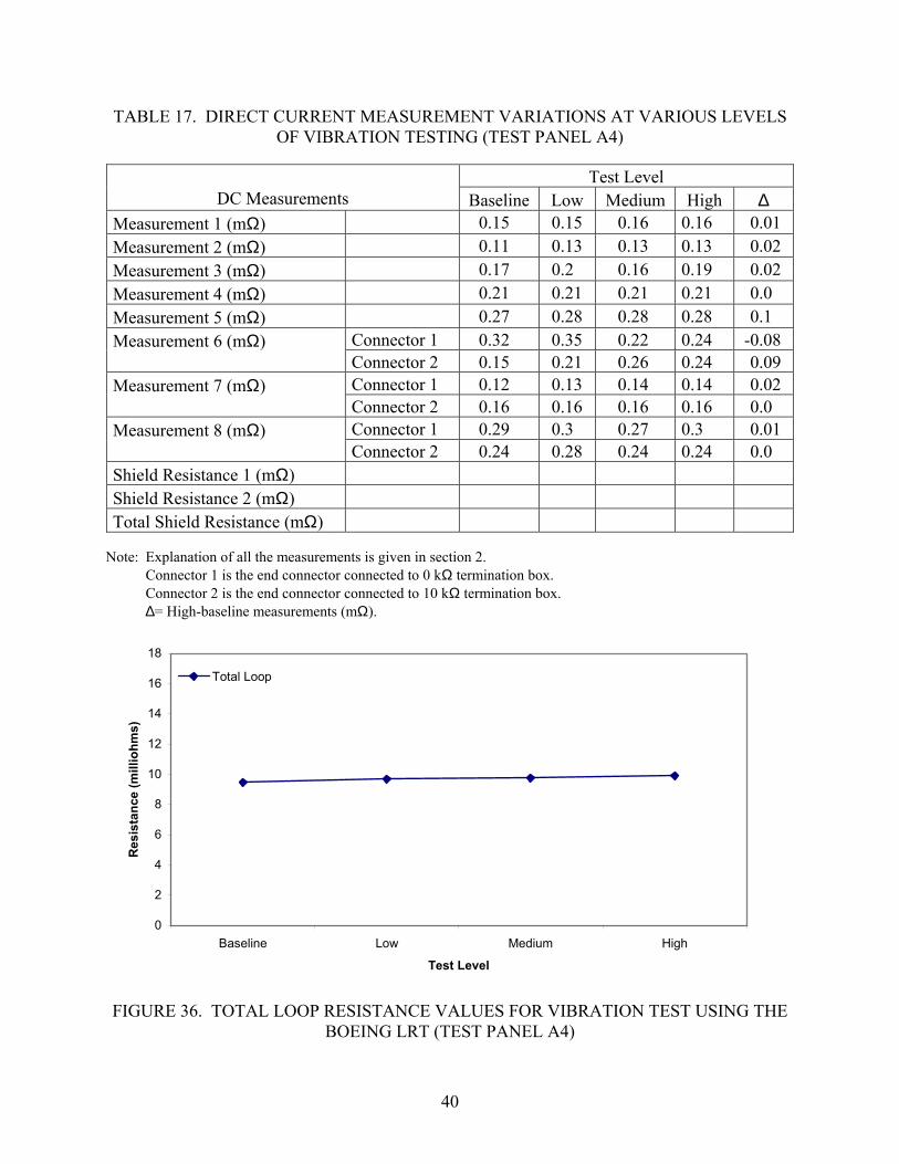
TABLE 17. DIRECT CURRENT MEASUREMENT VARIATIONS AT VARIOUS LEVELS OF VIBRATION TESTING (TEST PANEL A4)
Test Level DC Measurements Baseline Low Medium High ∆
Measurement 1 (mΩ) 0.15 0.15 0.16 0.16 0.01 Measurement 2 (mΩ) 0.11 0.13 0.13 0.13 0.02 Measurement 3 (mΩ) 0.17 0.2 0.16 0.19 0.02 Measurement 4 (mΩ) 0.21 0.21 0.21 0.21 0.0 Measurement 5 (mΩ) 0.27 0.28 0.28 0.28 0.1
Connector 1 0.32 0.35 0.22 0.24 -0.08 Measurement 6 (mΩ) Connector 2 0.15 0.21 0.26 0.24 0.09 Connector 1 0.12 0.13 0.14 0.14 0.02 Measurement 7 (mΩ) Connector 2 0.16 0.16 0.16 0.16 0.0 Connector 1 0.29 0.3 0.27 0.3 0.01 Measurement 8 (mΩ) Connector 2 0.24 0.28 0.24 0.24 0.0
Shield Resistance 1 (mΩ) Shield Resistance 2 (mΩ) Total Shield Resistance (mΩ)
Note: Explanation of all the measurements is given in section 2. Connector 1 is the end connector connected to 0 kΩ termination box.
Connector 2 is the end connector connected to 10 kΩ termination box. ∆= High-baseline measurements (mΩ).
0
2
4
6
8
10
12
14
16
18
Baseline Low Medium High
Test Level
Res
ista
nce
(mill
iohm
s)
Total Loop
FIGURE 36. TOTAL LOOP RESISTANCE VALUES FOR VIBRATION TEST USING THE BOEING LRT (TEST PANEL A4)
40

2.8.3 Observations (Vibration Tests).
The following observations were drawn after the data analysis and visual inspections:
• No loosening of connectors or screws was observed for test panel A4. Moreover, no other visual variations were observed at any level of testing.
• Variations in shield loop resistance and dc measurements were within the set tolerances for test panel A4.
• Connectors on test panel B4 were internally damaged during the medium- and high-level vibration tests. The connectors and backshells used in type B test panels were more susceptible to vibrations. The connectors and backshells were visually broken at the time of loop resistance degradation.
• Whenever longer barrel connectors are used, such as those tested on the type B panels, some form of additional mechanical support should be installed to protect the connector and backshell from vibration degradation.
2.9 MECHANICAL DEGRADATION TEST.
2.9.1 Test Procedure.
This test was performed to study the effects of mechanical degradation on wire shielding. The types of degradation performed on the test panels were stretching and loosening and cutting the shield braids. These tests were chosen as typical examples of damage that might occur to wire bundles in aircraft. For each severity level, the degradation was performed on all the shield braids on each side of the center connector, and also on the shield braids terminating at each end connector.
Test panels A3, A5, B3, and B5 were selected for this test, but test panel B3 was damaged during the initial mechanical degradation test and was not fit for further testing. Therefore, test panel B1 was used in place of B3 for mechanical degradation. Test panels types A and B require different procedures. Therefore, new test procedures were developed for test panel type B, as detailed in the following sections.
2.9.1.1 Low-Level Mechanical Degradation.
The shields of test panel A3 were stretched and loosened with pliers for the low-severity level test. Figure 37 shows the low-level mechanical degradation for test panel A3. For test panel B1, two of six shield wires were disconnected for the low-level degradation, as shown in figure 38.
41

Cut Shields
FIGURE 37. LOW-LEVEL MECHANICAL DEGRADATION (TEST PANEL TYPE A)
Removed Shielding Wires
FIGURE 38. LOW-LEVEL MECHANICAL DEGRADATION (TEST PANEL TYPE B)
42

2.9.1.2 Medium-Level Mechanical Degradation.
Figure 39 shows the medium-level mechanical degradation for test panel A3. The woven braid shields were cut in half with a cutter to simulate medium-level severity. For test panel B1, four of six shield wires were disconnected for the medium-level degradation, as shown in figure 40.
2.9.1.3 High-Level Mechanical Degradation.
The half cut shields of test panel A3 were further severed for the maximum severity level. Figure 41 shows the severed braid shields for the high-level mechanical degradation. For test panel B1, five of six shield wires were disconnected for high-level degradation, as shown in figure 42. Visual inspection, loop resistance, and dc resistance measurements were recorded initially and after mechanical degradation was performed at each severity level.
FIGURE 39. MEDIUM-LEVEL MECHANICAL DEGRADATION (TEST PANEL TYPE A)
43
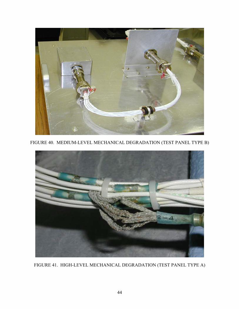
FIGURE 40. MEDIUM-LEVEL MECHANICAL DEGRADATION (TEST PANEL TYPE B)
FIGURE 41. HIGH-LEVEL MECHANICAL DEGRADATION (TEST PANEL TYPE A)
44
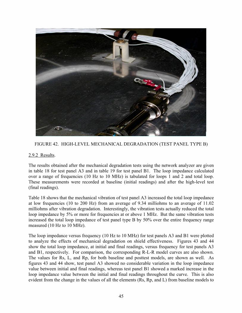
FIGURE 42. HIGH-LEVEL MECHANICAL DEGRADATION (TEST PANEL TYPE B) 2.9.2 Results.
The results obtained after the mechanical degradation tests using the network analyzer are given in table 18 for test panel A3 and in table 19 for test panel B1. The loop impedance calculated over a range of frequencies (10 Hz to 10 MHz) is tabulated for loops 1 and 2 and total loop. These measurements were recorded at baseline (initial readings) and after the high-level test (final readings).
Table 18 shows that the mechanical vibration of test panel A3 increased the total loop impedance at low frequencies (10 to 200 Hz) from an average of 9.34 milliohms to an average of 11.02 milliohms after vibration degradation. Interestingly, the vibration tests actually reduced the total loop impedance by 5% or more for frequencies at or above 1 MHz. But the same vibration tests increased the total loop impedance of test panel type B by 50% over the entire frequency range measured (10 Hz to 10 MHz).
The loop impedance versus frequency (10 Hz to 10 MHz) for test panels A3 and B1 were plotted to analyze the effects of mechanical degradation on shield effectiveness. Figures 43 and 44 show the total loop impedance, at initial and final readings, versus frequency for test panels A3 and B1, respectively. For comparison, the corresponding R-L-R model curves are also shown. The values for Rs, L, and Rp, for both baseline and posttest models, are shown as well. As figures 43 and 44 show, test panel A3 showed no considerable variation in the loop impedance value between initial and final readings, whereas test panel B1 showed a marked increase in the loop impedance value between the initial and final readings throughout the curve. This is also evident from the change in the values of all the elements (Rs, Rp, and L) from baseline models to
45
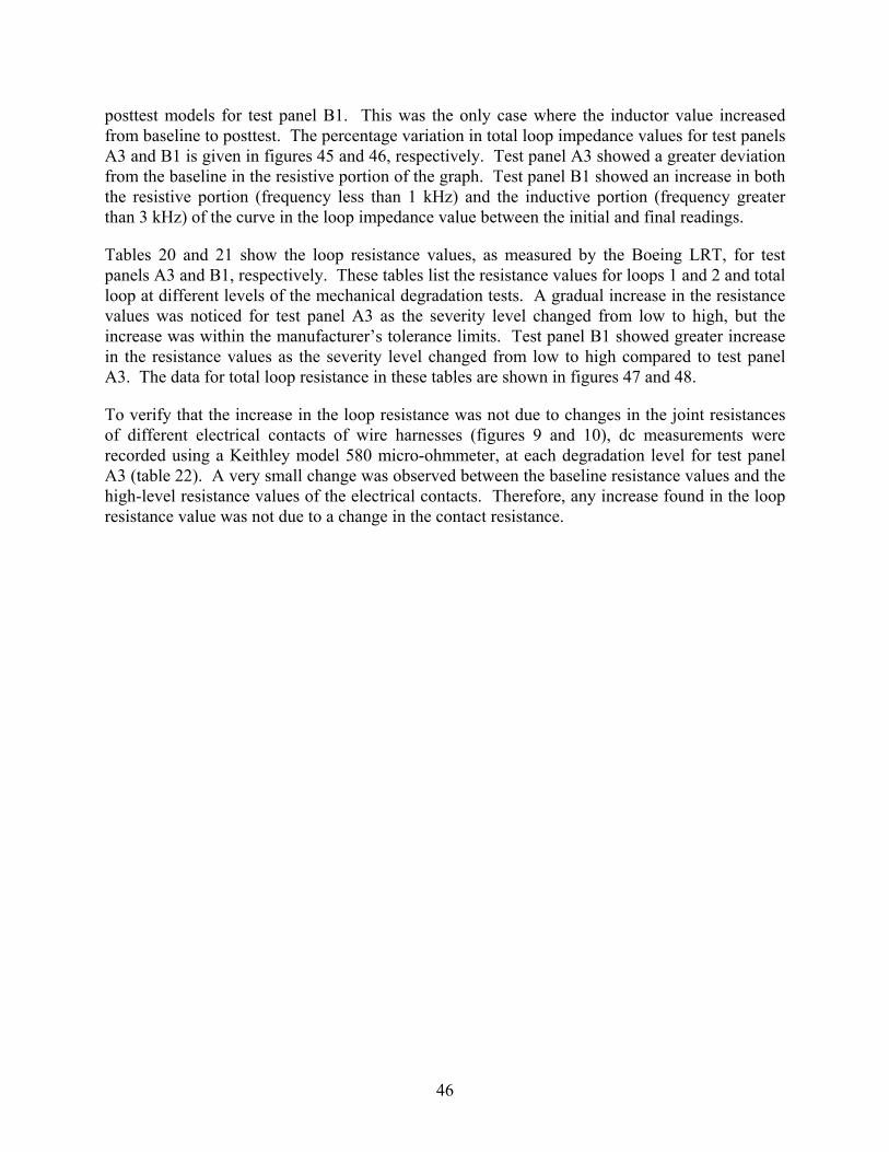
posttest models for test panel B1. This was the only case where the inductor value increased from baseline to posttest. The percentage variation in total loop impedance values for test panels A3 and B1 is given in figures 45 and 46, respectively. Test panel A3 showed a greater deviation from the baseline in the resistive portion of the graph. Test panel B1 showed an increase in both the resistive portion (frequency less than 1 kHz) and the inductive portion (frequency greater than 3 kHz) of the curve in the loop impedance value between the initial and final readings.
Tables 20 and 21 show the loop resistance values, as measured by the Boeing LRT, for test panels A3 and B1, respectively. These tables list the resistance values for loops 1 and 2 and total loop at different levels of the mechanical degradation tests. A gradual increase in the resistance values was noticed for test panel A3 as the severity level changed from low to high, but the increase was within the manufacturer’s tolerance limits. Test panel B1 showed greater increase in the resistance values as the severity level changed from low to high compared to test panel A3. The data for total loop resistance in these tables are shown in figures 47 and 48.
To verify that the increase in the loop resistance was not due to changes in the joint resistances of different electrical contacts of wire harnesses (figures 9 and 10), dc measurements were recorded using a Keithley model 580 micro-ohmmeter, at each degradation level for test panel A3 (table 22). A very small change was observed between the baseline resistance values and the high-level resistance values of the electrical contacts. Therefore, any increase found in the loop resistance value was not due to a change in the contact resistance.
46
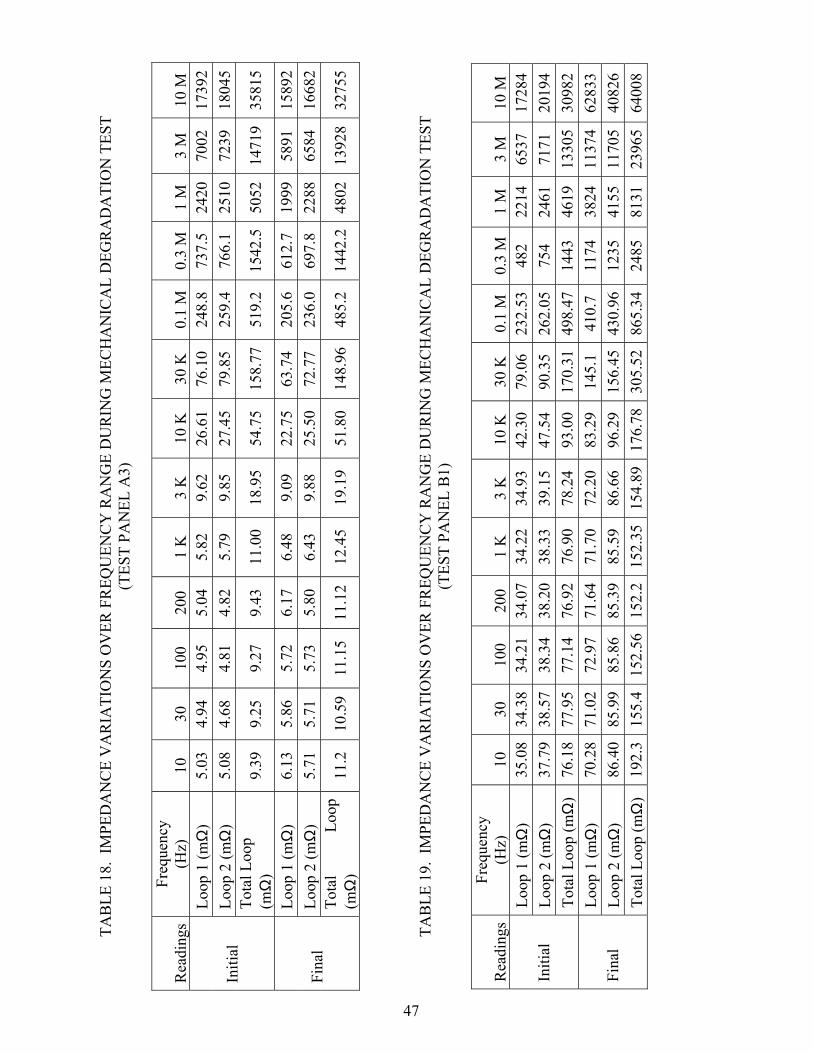
TAB
LE 1
8. I
MPE
DA
NC
E V
AR
IATI
ON
S O
VER
FR
EQU
ENC
Y R
AN
GE
DU
RIN
G M
ECH
AN
ICA
L D
EGR
AD
ATI
ON
TES
T (T
EST
PAN
EL A
3)
Rea
ding
s Fr
eque
ncy
(Hz)
10
30
10
0 20
0 1
K
3 K
10
K
30 K
0.
1 M
0.
3 M
1
M
3 M
10
M
Loop
1 (m
Ω)
5.03
4.94
4.95
5.04
5.82
9.62
26.6
176
.10
248.
873
7.5
2420
7002
1739
2Lo
op 2
(mΩ
) 5.
08
4.
684.
814.
825.
799.
8527
.45
79.8
525
9.4
766.
125
1072
3918
045
Initi
al
Tota
l Loo
p (m
Ω)
9.39
9.
259.
279.
4311
.00
18.9
554
.75
158.
7751
9.2
1542
.550
5214
719
3581
5
Loop
1 (m
Ω)
6.13
5.86
5.72
6.17
6.48
9.09
22.7
563
.74
205.
661
2.7
1999
5891
1589
2Lo
op 2
(mΩ
) 5.
71
5.
715.
735.
806.
439.
8825
.50
72.7
723
6.0
697.
822
8865
8416
682
Fina
l To
tal
Loop
(m
Ω)
11.2
10
.59
11.1
511
.12
12.4
519
.19
51.8
014
8.96
485.
214
42.2
4802
1392
832
755
47
TAB
LE 1
9. I
MPE
DA
NC
E V
AR
IATI
ON
S O
VER
FR
EQU
ENC
Y R
AN
GE
DU
RIN
G M
ECH
AN
ICA
L D
EGR
AD
ATI
ON
TES
T (T
EST
PAN
EL B
1)
Rea
ding
s Fr
eque
ncy
(Hz)
10
30
10
0 20
0 1
K
3 K
10
K
30 K
0.
1 M
0.
3 M
1
M
3 M
10
M
Loop
1 (m
Ω)
35.0
8
34
.38
34.2
134
.07
34.2
234
.93
42.3
079
.06
232.
5348
2 22
1465
3717
284
Loop
2 (m
Ω)
37.7
9
38.5
738
.34
38.2
038
.33
39.1
547
.54
90.3
526
2.05
754
2461
7171
2019
4In
itial
To
tal L
oop
(mΩ
) 76
.18
77
.95
77.1
476
.92
76.9
078
.24
93.0
017
0.31
498.
4714
4346
1913
305
3098
2Lo
op 1
(mΩ
) 70
.28
71
.02
72.9
771
.64
71.7
072
.20
83.2
914
5.1
410.
711
7438
2411
374
6283
3Lo
op 2
(mΩ
) 86
.40
85
.99
85.8
685
.39
85.5
986
.66
96.2
915
6.45
430.
9612
3541
5511
705
4082
6Fi
nal
Tota
l Loo
p (m
Ω)
192.
3
15
5.4
152.
5615
2.2
152.
3515
4.89
176.
7830
5.52
865.
3424
8581
3123
965
6400
8
110100
1000
1000
0
1000
00
110
100
1000
1000
010
0000
1000
000
1000
0000
Freq
uenc
y (H
z)
Impedance (milliohms)
Bas
elin
eB
asel
ine
Mod
elP
ost t
est
Pos
t Tes
t Mod
el
Bas
elin
e
Mod
el
Rs
= 9.
3mΩ
L
=
0.
81m
H
Rp
= 53
Ω
48
Post
Tes
t M
odel
Rs
= 11
mΩ
L
=
0.
81m
H
Rp
= 42
Ω
FI
GU
RE
43.
TOTA
L LO
OP
IMPE
DA
NC
E C
HA
RA
CTE
RIS
TIC
S B
EFO
RE
AN
D A
FTER
MEC
HA
NIC
AL
DEG
RA
DA
TIO
N
TEST
(TES
T PA
NEL
A3)
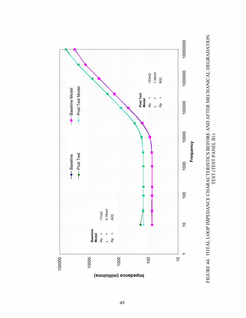
10100
1000
1000
0
1000
00
110
100
1000
1000
010
0000
1000
000
1000
0000
Freq
uenc
y
Impedance (milliohms)
Bas
elin
eB
asel
ine
Mod
el
Pos
t Tes
t P
ost T
est M
odel
Bas
elin
e
Mod
el
Rs
=
77m
Ω
L
=
0.76
mH
Rp
=
42Ω
49
Post
Tes
t M
odel
Rs
=
15
3mΩ
L
=
1.35
mH
Rp
=
90
Ω
FI
GU
RE
44.
TOTA
L LO
OP
IMPE
DA
NC
E C
HA
RA
CTE
RIS
TIC
S B
EFO
RE
AN
D A
FTER
MEC
HA
NIC
AL
DEG
RA
DA
TIO
N
TEST
(TES
T PA
NEL
B1)

-10.00
0.00
10.00
20.00
30.00
40.00
50.00
10 100 1,000 10,000 100,000 1,000,000 10,000,000
Frequency (Hz)
Perc
enta
ge V
aria
nce
from
Bas
elin
e
Total Loop
FIGURE 45. PERCENTAGE LOOP IMPEDANCE VARIATION AFTER MECHANICAL
DEGRADATION TEST (TEST PANEL A3)
0
20
40
60
80
100
120
140
160
180
200
10 100 1,000 10,000 100,000 1,000,000 10,000,000
Frequency (Hz)
Perc
enta
ge V
aria
nce
from
Bas
elin
e Total Loop
FIGURE 46. PERCENTAGE LOOP IMPEDANCE VARIATION AFTER MECHANICAL
DEGRADATION TEST (TEST PANEL B1)
50

TABLE 20. LOOP RESISTANCE VALUES FOR MECHANICAL DEGRADATION TEST USING THE BOEING LRT (TEST PANEL A3)
Test Level Loop 1 (mΩ)
Loop 2 (mΩ)
Total Loop (mΩ)
R-L-R Model Total Loop Rs (mΩ)
Visual Degradation
Baseline 4.92 4.74 9.17 9.3 None Low 5.14 4.97 9.48 None Medium 5.5 5.2 9.81 Yes High 5.67 5.39 10.36 11 Yes
TABLE 21. LOOP RESISTANCE VALUES FOR MECHANICAL DEGRADATION TEST USING THE BOEING LRT (TEST PANEL B1)
Test Level Loop 1 (mΩ) Loop 2 (mΩ)
Total Loop (mΩ)
R-L-R Model Total Loop Rs (mΩ)
Visual Degradatio
n Baseline 21.5 41.52 68.72 77 None Low 30.45 59.06 88.43 Yes Medium 40.81 86.38 124.09 Yes High 71.07 80.73 149.26 153 Yes
TABLE 22. DIRECT CURRENT MEASUREMENTS FOR MECHANICAL
DEGRADATION TEST (TEST PANEL A3)
Test Level DC Measurements Baseline Low Medium High ∆
Measurement 1 (mΩ) 0.12 0.11 0.11 0.12 0.0 Measurement 2 (mΩ) 0.19 0.21 0.21 0.21 0.02 Measurement 3 (mΩ) 0.26 0.29 0.28 0.26 0.0 Measurement 4 (mΩ) 0.1 0.1 0.1 0.11 0.01 Measurement 5 (mΩ) 0.1 0.1 0.1 0.11 0.01
Connector 1 0.14 0.16 0.16 0.15 0.01 Measurement 6 (mΩ) Connector 2 0.09 0.14 0.15 0.15 0.06 Connector 1 0.07 0.07 0.07 0.07 0.0 Measurement 7 (mΩ) Connector 2 0.07 0.09 0.09 0.09 0.02 Connector 0.25 0.26 0.25 0.25 0.0 Measurement 8 (mΩ) Connector 2 0.21 0.21 0.2 0.21 0.0
Shield Resistance 1 (mΩ) 3.2 3.27 3.45 3.72 0.52 Shield Resistance 2 (mΩ) 3.39 3.42 3.67 3.9 0.51 Total Shield Resistance (mΩ) 7.31 7.46 7.86 8.42 1.11
Note: Explanation of all the measurements is given in section 2. Connector 1 is the end connector connected to 0 kΩ termination box.
Connector 2 is the end connector connected to 10 kΩ termination box. ∆= High-baseline measurements (mΩ).
51

0
2
4
6
8
10
12
14
16
18
20
Baseline Low Medium High
Test Level
Res
ista
nce
(mill
iohm
s)
Total Loop
Visually degraded
FIGURE 47. TOTAL LOOP RESISTANCE VALUES FOR MECHANICAL DEGRADATION TEST USING THE BOEING LRT (TEST PANEL A3)
20
40
60
80
100
120
140
160
180
200
220
Baseline Low Medium HighTest Level
Res
ista
nce
(mill
iohm
s)
Total Loop
Visually degraded
FIGURE 48. TOTAL LOOP RESISTANCE VALUES FOR MECHANICAL DEGRADATION TEST USING THE BOEING LRT (TEST PANEL B1)
52

2.9.3 Observations (Mechanical Degradation Tests).
The following observations were drawn after data analysis and visual inspections:
• Mechanical degradation affected the shield impedance more than any other environmental test.
• Shield loop impedance and dc measurements were within the manufacturer’s tolerance limits at all degradation levels, for all type A test panels and wire bundles.
• Visual degradation was observed before there was any abrupt increase in loop impedance.
• In the case of test panel A, where each shield was partially cut for the mechanical degradation, the change in the loop impedance showed as a change in the loop resistance only.
• In the case of test panel B, when shielding wires were fully cut for the mechanical degradation, the change in the loop impedance showed as a change in both the loop resistance and inductance, with the loop resistance having the highest percentage of the change.
2.10 COMBINATION TEST.
2.10.1 Test Procedure.
The purpose of this test was to study the effects of a combination of environmental and mechanical degradations on a wire bundle in aircraft. Test panels A5 and B5 were subjected to these environmental conditions: loop resistance measurements, dc bond and joint resistance measurements, and visual inspections. Each of these measurements and inspections were performed after each test was completed.
The procedure for each individual test of the combination was the same as mentioned earlier. The tests were carried out in the following sequence:
• Vibration test • Temperature and altitude test • Salt spray and humidity test • Mechanical degradation test The final measurements at the end of combined tests showed the overall effects of the worst possible environmental and mechanical degradation.
2.10.2 Results.
The results obtained after the combination tests, using a network analyzer, are given in table 23 for test panel A5. The loop impedance calculated over a range of frequencies (10 Hz to 10 MHz)
53

is tabulated for loops 1 and 2, and total loop. These measurements were recorded at baseline and after the high-level salt and fog and mechanical degradation tests.
The loop impedance versus frequency (10 Hz to 10 MHz) for test panel A5 were plotted to analyze the effects of the combination test on shield effectiveness. Figure 49 shows the total loop impedance versus frequency for test panel A5. For comparison, the corresponding R-L-R model curves are also shown. This figure shows the total loop impedance values for the baseline, salt and fog, and mechanical degradation tests. The values for Rs, L, and Rp, for both baseline and posttest models, are shown as well. As shown in figure 49, the test panel showed no considerable variation in the loop impedance values between the initial and final readings. A minute change in the impedance value is shown only in the resistive portion of the graph (for frequencies less than 1 kHz). This is also evident from the change in the values of Rs from baseline models to posttest models for both panels. The values for Rp also changed slightly, but the value of the inductor element of the model circuit remained constant. Test panel A5 showed no considerable variation in loop impedance value before and after the degradation tests.
To verify that the increase in the loop resistance was not due to changes in the joint resistances of different contacts, as seen in figures 9 and 10, the dc measurements were recorded using the Keithley model 580 micro-ohmmeter for test panel A5 (table 24), following the procedure in section 2.3. The difference between the baseline resistance value and the high-level resistance value given in this table is negligible.
Tables 25 and 26 show the loop resistance values, as measured by the Boeing LRT, for test panels A5 and B5, respectively. These tables list the resistance values for loops 1 and 2 and total loop at different levels of the combination tests. A gradual increase in the resistance values was noticed for test panel A5 after each degradation test was performed. Test panel B5 showed no noticeable increase after the temperature and altitude test. However, abnormal results were observed during the vibration tests. The loop resistance value became unstable during the salt spray and humidity test. Therefore, the mechanical degradation test was not performed. Further investigation revealed that the vibration tests internally damaged the connectors. The data for total loop resistance are shown in figures 50 and 51.
54

TA
BLE
23.
LO
OP
RES
ISTA
NC
E V
AR
IATI
ON
S O
VER
FR
EQU
ENC
Y R
AN
GE
DU
RIN
G C
OM
BIN
ATI
ON
TES
TS
(TES
T PA
NEL
A5)
Test
s Fr
eque
ncy
(Hz)
30
10
0 20
0 1
K
3 K
10
K
30 K
0.
1 M
0.
3 M
1
M
3 M
10
M
Loop
1
(mΩ
) 4.
87
5.
305.
395.
486.
119.
3724
.75
71.4
823
2.13
686.
122
5365
3115
107
Loop
2
(mΩ
) 5.
05
4.97
5.06
5.13
5.98
9.78
27.1
677
.04
251.
8874
1.12
2424
6914
1791
7B
asel
ine
Tota
l Lo
op
(mΩ
) 9.
63
9.57
9.63
9.69
11.1
518
.70
51.4
414
9.12
488.
9814
50.2
4755
1372
933
573
Loop
1
(mΩ
) 7.
68
7.
557.
597.
608.
1711
.32
26.6
873
.16
234.
769
3.8
2279
6671
1538
9
Loop
2
(mΩ
) 6.
63
6.18
6.79
6.80
7.48
10.5
725
.98
76.6
123
4.85
699.
722
8667
1518
971
Salt
and
Fog
Tota
l Lo
op
(mΩ
) 13
.03
12
.40
12.4
412
.49
13.8
020
.02
49.7
513
9.64
451.
4713
34.1
4444
1296
834
945
Loop
1
(mΩ
) 10
.08
9.73
9.70
9.68
10.2
713
.12
28.6
576
.25
243.
371
6.2
2332
6730
1483
9
Loop
2
(mΩ
) 9.
46
9.
259.
219.
269.
8212
.33
26.3
570
.91
228.
167
0.1
2193
6371
1779
4M
echa
nica
l D
egra
datio
n To
tal
Loop
(m
Ω)
17.7
4
16
.20
16.3
116
.32
17.5
223
.42
54.2
115
0.71
488.
614
40.4
4541
1392
637
118
10
55

110100
1000
1000
0
1000
00
110
100
1000
1000
010
0000
1000
000
1000
0000
Freq
uenc
y (H
z)
Impedance (milliohms)
Base
line
Base
line
Mod
el
Post
Tes
tPo
st T
est M
odel
Bas
elin
e
Mod
el
Rs
=
9.
75m
Ω
L
=
0.79
mH
Rp
=
46
Ω
56
Post
Tes
t M
odel
Rs
=
16.6
L
=
0.79
Rp
=
55
FIG
UR
E 49
. TO
TAL
LOO
P IM
PED
AN
CE
CH
AR
AC
TER
ISTI
CS
BEF
OR
E A
ND
AFT
ER C
OM
BIN
ATI
ON
TES
TS
(TES
T PA
NEL
A5)

TAB
LE 2
4. D
IREC
T C
UR
REN
T M
EASU
REM
ENT
VA
RIA
TIO
NS
FOR
CO
MB
INA
TIO
N T
ESTS
(TES
T PA
NEL
A5)
Test
Lev
el
DC
Mea
sure
men
ts
Bas
elin
e V
ibra
tion
Tem
pera
ture
an
d A
ltitu
de
Salt
and
Fog
Mec
hani
cal
∆ M
easu
rem
ent 1
(mΩ
)
0.
15
0.2
0.
27
0.27
0.
12M
easu
rem
ent 2
(mΩ
)
0.
25
0.27
0.32
0.
32
0.07
Mea
sure
men
t 3 (m
Ω)
0.14
0.
140.
16
0.16
0.
02M
easu
rem
ent 4
(mΩ
)
0.
15
0.17
0.43
0.
43
0.28
Mea
sure
men
t 5 (m
Ω)
0.21
0.
210.
22
0.22
0.
01C
onne
ctor
1
0.2
0.2
0.
19
0.19
0.
01
Mea
sure
men
t 6 (m
Ω)
Con
nect
or 2
0.
17
0.27
0.51
0.
51
0.34
C
onne
ctor
1
0.25
0.
26
0.
26
0.26
0.
01
Mea
sure
men
t 7 (m
Ω)
Con
nect
or 2
0.
14
0.17
0.54
0.
54
0.40
C
onne
ctor
1
0.35
0.
35
0.
37
0.37
0.
02
Mea
sure
men
t 8 (m
Ω)
Con
nect
or 2
0.
21
0.21
0.47
0.
47
0.26
Sh
ield
Res
ista
nce
1 (m
Ω)
3.
23
4.87
Sh
ield
Res
ista
nce
2 (m
Ω)
3.26
4.
88To
tal S
hiel
d R
esis
tanc
e (m
Ω)
7.42
11
.31
57
N
ote:
Ex
plan
atio
n of
all
the
mea
sure
men
ts is
giv
en in
sect
ion
2.
C
onne
ctor
1 is
the
end
conn
ecto
r con
nect
ed to
0 k
Ω te
rmin
atio
n bo
x.
Con
nect
or 2
is th
e en
d co
nnec
tor c
onne
cted
to 1
0 kΩ
term
inat
ion
box.
Th
e m
easu
rem
ents
are
take
n at
the
end
of d
egra
datio
n te
st.
∆= F
inal
-bas
elin
e m
easu
rem
ents
(mΩ
).
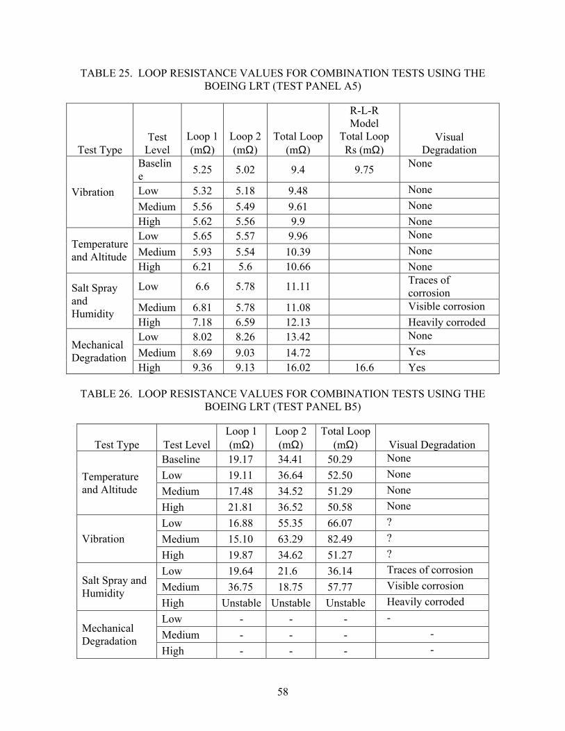
TABLE 25. LOOP RESISTANCE VALUES FOR COMBINATION TESTS USING THE BOEING LRT (TEST PANEL A5)
Test Type Test
Level Loop 1 (mΩ)
Loop 2 (mΩ)
Total Loop(mΩ)
R-L-R Model
Total Loop Rs (mΩ)
Visual Degradation
Baseline 5.25 5.02 9.4 9.75 None
Low 5.32 5.18 9.48 None Medium 5.56 5.49 9.61 None
Vibration
High 5.62 5.56 9.9 None Low 5.65 5.57 9.96 None Medium 5.93 5.54 10.39 None Temperature
and Altitude High 6.21 5.6 10.66 None
Low 6.6 5.78 11.11 Traces of corrosion
Medium 6.81 5.78 11.08 Visible corrosion
Salt Spray and Humidity
High 7.18 6.59 12.13 Heavily corroded Low 8.02 8.26 13.42 None Medium 8.69 9.03 14.72 Yes Mechanical
Degradation High 9.36 9.13 16.02 16.6 Yes
TABLE 26. LOOP RESISTANCE VALUES FOR COMBINATION TESTS USING THE
BOEING LRT (TEST PANEL B5)
Test Type Test Level Loop 1 (mΩ)
Loop 2 (mΩ)
Total Loop (mΩ) Visual Degradation
Baseline 19.17 34.41 50.29 None Low 19.11 36.64 52.50 None Medium 17.48 34.52 51.29 None
Temperature and Altitude
High 21.81 36.52 50.58 None Low 16.88 55.35 66.07 ? Medium 15.10 63.29 82.49 ? Vibration High 19.87 34.62 51.27 ? Low 19.64 21.6 36.14 Traces of corrosion Medium 36.75 18.75 57.77 Visible corrosion Salt Spray and
Humidity High Unstable Unstable Unstable Heavily corroded Low - - - - Medium - - - - Mechanical
Degradation High - - - -
58

0
5
10
15
20
Baseline Vibration Temp & Altitude Salt Spray & Humidity Mechanical
Degradation Test Type
Res
ista
nce
(mill
iohm
s)
Total Loop
Visually degraded
FIGURE 50. TOTAL LOOP RESISTANCE VALUES FOR COMBINATION TESTS USING
THE BOEING LRT (TEST PANEL A5)
25.00
30.00
35.00
40.00
45.00
50.00
55.00
60.00
65.00
70.00
75.00
Baseline Temp & Altitude Vibration Salt & Fog Mechanical
Degradation Test Type
Res
ista
nce
(mill
iohm
s)
Total Loop
Visually degraded
Impedance Value Unstable
FIGURE 51. TOTAL LOOP RESISTANCE VALUES FOR COMBINATION TESTS USING THE BOEING LRT (TEST PANEL B5)
59

2.10.3 Observations (Combination Tests).
• Variation in loop resistance was within acceptable tolerance limits after all the degradation tests. Figure 52 shows the dB variance in loop resistance value after each degradation test on panel A5 (combination).
• Mechanical degradation has a more degrading effect on the loop impedance than any other environmental test.
• No significant change was measured in bonding, grounding, and connection resistances after all the degradation tests.
-5
0
5
10
15
20
25
Baseline Vibration Temp/Alt Salt & Fog Mech.
Degradation Test Type
dB V
aria
nce
Visually degraded
FIGURE 52. LOOP RESISTANCE VARIATION AFTER EACH DEGRADATION TEST 3. OVERALL OBSERVATIONS.
The following observations were drawn after analyzing and comparing the data from all tests.
• The temperature and altitude tests had no effect on the physical or visual characteristics of shielding for either test panels type A or B. The loop resistance for test panel A increased by 4 mΩ from the baseline to the high-level degradation test, and for test panel B, it increased by 10 mΩ.
• The Salt spray and humidity testing corroded the ground plane, center bulkhead, screws, and exposed shield braids for both test panels. A slight increase was observed in the shield resistance (less than 2 mΩ) after the high-level tests of each test panel.
• Vibration testing did not vary the visual characteristics for both types of test panels. The shield loop resistance did not significantly increase at any level of degradation for test
60

panel A. However, the connector backshells were broken during the testing for test panel type B and the resistance of the shielding went to open circuit. Test panel type B was more susceptible to vibration testing due to the size of the connector backshells.
• Mechanical degradation testing affected the physical and visual characteristics of shielding for both types of the test panels. The loop resistance increased from baseline to high level of testing by 2 mΩ for test panel A, and for test panel B, it increased by 80 mΩ.
• Combination testing affected the physical and visual characteristics for both types of test panels. The loop resistance value increased slightly from baseline to high level of testing by 6 mΩ for test panel A, and it went to open circuit for test panel B because the connectors were internally damaged during the vibration testing.
• Physical degradation of shielded wire harnesses was visually observed before or at the same time of any significant loop resistance increase. Hence, it is recommended that visual and physical inspection be made the primary means for detecting shield degradation and shields should be repaired when degradation is observed. However, loop resistance measurements are advantageous when used to indicate shield degradation of those wire harnesses that are not easily accessible for visual inspection, provided the measurements are performed by trained and skilled operators.
• A further mechanical study appears warranted to investigate the shield degradation effects of fully broken and floating grounding wires on various shield configurations. That study should involve loop resistance, swept-frequency impedance, and shield effectiveness measurements to compile the proper maintenance procedures.
4. REFERENCES.
1. RTCA/DO-160D, Environmental Conditions and Test Procedures for Airborne Equipment.
2. ASTM B 117, Standard Practice for Operating Salt Spray (Fog) Apparatus.
3. Figure 8-4 of “Robust Random Vibration Test Curves for Equipment Installed in Fixed-Wing Aircraft With Turbojet or Turbofan Engines” from RTCA/DO-160D.
61
5. GLOSSARY.
Airworthiness Date—The date on which it is determined that an entire aircraft, or one of its component parts, meets its type design (certification) specifications and is in a safe condition to fly.
Baseline Tests—Initial tests performed on the test panels before they were subjected to any degradation tests.
Boeing Loop Resistance Tester (LRT)—A Boeing LRT is a portable electrical device that measures the resistance (at 200 Hz) of a loop of conductive material without disturbing or disconnecting the loop. It is typically used in industry to measure the shield loop resistance of an aircraft harness or wire bundle with two clamp-on probes without disturbing or removing any of the harness connectors or backshells. One probe is used to induce a known current in the loop. The other probe is used to measure the resulting voltage from which the loop resistance may be determined. It may also be used in joint mode to measure the resistance between components of the harness and structure.
DC micro-ohmmeter—A portable electrical instrument capable of making low resistance direct current (dc) measurements. It is typically used for making joint resistance measurements. The Keithley model 580 micro-ohmmeter used in this study was capable of making dc resistance measurements from 10 µΩ to 200 kΩ.
Network Analyzer—The network analyzer is an electronic device used to measure electrical impedance over a wide range of frequencies. Using a pair of clamp-on probes, a Hewlett-Packard network analyzer was used to determine the shield loop impedance of the test wire bundles over a range of frequencies selected from 10 Hz to 10 MHz in this study.
Overbraided Wire Bundle—A wire bundle whose length is entirely covered (shielded) with an outer woven braid of fine-tinned copper wires.
Shield—A conductor that is grounded to an equipment case or aircraft structure at both ends. It is routed in parallel with, and bound within or around, a cable bundle and grounded at both ends within the cable bundle. It usually is a wire braid around some of the wires or cables in the bundle, or it may be a metallic conduit or channel in which the cable bundle is laid. The effect of the shield is to provide a low resistance path between equipment so connected.
Shielded Wire bundle—A wire bundle that contains one or more shields.
Test Panel—An aluminum panel with cable termination boxes and brackets attached. Panels were constructed for this study to simulate an aircraft structure and act as a ground plane and mount for the cable wire bundles used in this study.
Visual Inspection—Procedure adopted to check for physical degradation.
Wire Bundle—A group of wires routed together that connect two or more pieces of equipment.
62

APPENDIX A—TEST PROCEDURE FOR THE BOEING LOOP RESISTANCE TESTER
A.1 IMPORTANT FEATURES. • The Boeing loop resistance tester (LRT), when used in the loop mode, is used for
measuring the resistance of electronic cable shielding installed in aircraft without requiring the cables to be disconnected. When operated in joint mode, the tester also has the capability of isolating a bad (higher than normal) resistance joint before removal of the cable.
• The loop mode of the tester uses two clamp-around coupler probes. The drive coupler probe magnetically induces a low power 200-Hz alternating current onto the cable shield and measures the voltage around the loop. The sense coupler probe measures the current induced in the loop. The complex ratio of these measurements can then be used to determine the shield loop resistance, which is an indicator of the quality of the electrical bonds between the cable shield, backshells, connectors, and metallic structures.
• In joint mode, the tester measures the joint voltage and loop current, giving joint impedance.
• The frequency of operation is 200 Hz, which provides good skin-depth penetration such that the measurements agree reasonably well with direct current resistance measurements.
The LRT is shown in figure A-1.
A.2 MEASUREMENT PROCEDURE. • Turn on the tester.
• Lift up the red protective cover and place the switch in the RUN position.
• Press the ON/OFF button on the center display. The loop impedance device will now run through a startup self-check.
• Connect the coupler probes to the LRT and place the other end on the wires to be tested.
• Place the mode switch into the loop mode.
• After the self-test is completed, the display will read BATTERY # # % showing the percentage charge on the battery; recharge the battery if needed. The display will then read PRESS START.
• Press the start button from either of the two couplers attached to the coupler probes to the start loop impedance measurement.
A-1

FIGURE A-1. LOOP RESISTANCE TESTER • The red light emitting diode (LED) on the couplers will turn green, and the display will
go blank.
• The LEDs start blinking green, and the center display will read LOOPVALUE, which is followed by the loop resistance in mΩ.
• If the display reads UNSTABLE, press the ON/OFF button to reset the tester and retake the measurements.
Figure A-2 shows the couplers probes attached to the LRT.
If the coupler probes have detected a loop impedance out of tolerance, then adopt the following procedures:
• Place the mode switch to joint mode.
• Connect the joint probes to isolate the bad joint, where the change in resistance occurred. (The tips of the joint probes are spring loaded.) While taking a measurement, press down on the probes for proper contact. Note that the coupler probes stay connected in the joint mode also.
• The LEDs will turn from red to green and the measurement will be displayed.
A-2

FIGURE A-2. COUPLER PROBES ATTACHED TO THE LRT Figure A-3 shows the joint probes attached to the LRT.
FIGURE A-3. JOINT PROBES ATTACHED TO THE LRT
A-3/A-4

APPENDIX B—TEST PROCEDURE FOR THE HEWLETT-PACKARD MODEL 8751A NETWORK ANALYZER
The Hewlett-Packard network analyzer uses a combination of front panel (hard keys) and soft keys. The ‘hard keys’ are grouped by function and provide access to various soft key menus. These menus list the possible choices for a particular function, with each choice corresponding to one of the eight soft keys located to the right of the CRT. The hard keys are represented by text surrounded by a box xxx and the soft keys are shown in BOLD ITALICS for this test procedure. Setup the apparatus for testing:
• The Pearson Clamp-On Current Monitor (P/N 3525) and Current Injection Probe (P/N CIP9136) are clamped around the wire bundle to be monitored.
• The radio frequency output from the network analyzer is connected to the current injection probe. This is responsible for current flow in the wire bundle (test article) through transformer action.
• The output from the Pearson Current Monitor is connected to the input port B of the analyzer. Another wire with the same number of turns as the test article is passed through the Current Injection Probe only and the voltage developed across this single loop is input to the input port A of the analyzer.
Figure B-1 shows the test setup using the network analyzer.
FIGURE B-1. TEST SETUP FOR IMPEDANCE MEASUREMENT
B-1

Test the shield impedance response of a wire bundle with the network analyzer:
• Turn the switch line on. The analyzer should power up with no error messages displayed, in which case, the analyzer has passed its internal diagnostics and is functioning properly.
• Press Meas from ‘Response Group’ and select INPUT PORTS; then select A for Ch1 and B
for Ch2. • Select the frequency range: 10 Hz to 10 MHz.
• Press Start from the stimulus group and enter the starting frequency (10 Hz) from the entry group.
• Press Stop and enter the last frequency (10 MHz).
• Press Format from Response Group and select for LOG MAG for both channels. • Press Menu from the stimulus group and select SWEEP TYPE MENU followed by LOG FRE
selection for both Ch1 and Ch2. This will give a logarithmic frequency scale for both channels. Then press RETURN to return to the menu.
• Select POWER and set it to 13 dBm. Then press RETURN to return to the menu.
• Select NUMBER OF POINTS; 801 will be suitable.
• Press Display and select DUAL CHAN ON to display the inputs from both ports simultaneously.
• Press Avg from response group, select IF BW and then press IF BW AUTO.
• Remove RF OUT of the network analyzer from the current injection probe, terminate it in a 50 Ω load and the keep the rest of the setup the same. This load was selected as it gives perfect matching.
• Press Display to select DEFINE TRACE and then put the uncoupled reading into memory from the DATA→ MEMORY key.
• Connect RF OUT again to the current injection probe and select DATA-MEMORY. This will reduce interference impairments to give improved measurements.
B-2
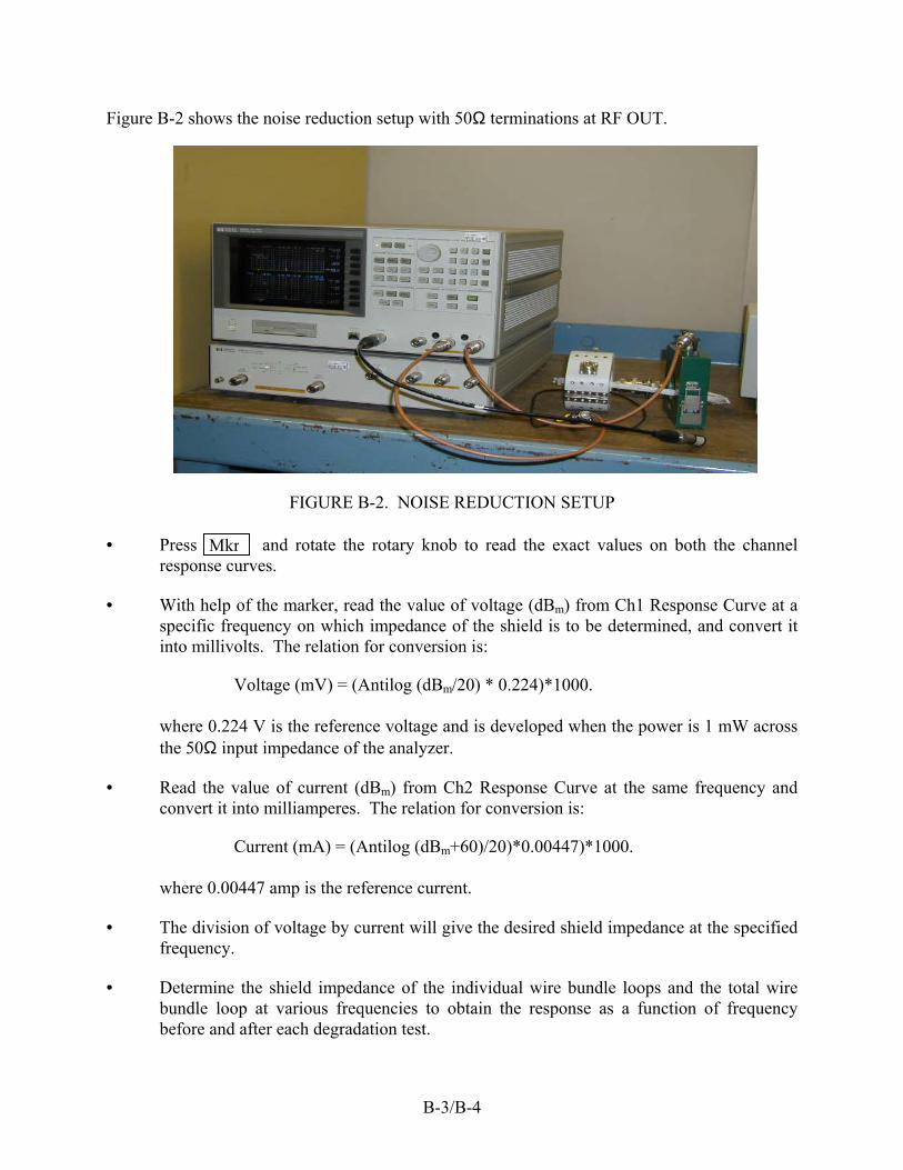
Figure B-2 shows the noise reduction setup with 50Ω terminations at RF OUT.
FIGURE B-2. NOISE REDUCTION SETUP • Press and rotate the rotary knob to read the exact values on both the channel
response curves. Mkr
• With help of the marker, read the value of voltage (dBm) from Ch1 Response Curve at a specific frequency on which impedance of the shield is to be determined, and convert it into millivolts. The relation for conversion is:
Voltage (mV) = (Antilog (dBm/20) * 0.224)*1000. where 0.224 V is the reference voltage and is developed when the power is 1 mW across the 50Ω input impedance of the analyzer.
• Read the value of current (dBm) from Ch2 Response Curve at the same frequency and convert it into milliamperes. The relation for conversion is:
Current (mA) = (Antilog (dBm+60)/20)*0.00447)*1000.
where 0.00447 amp is the reference current.
• The division of voltage by current will give the desired shield impedance at the specified frequency.
• Determine the shield impedance of the individual wire bundle loops and the total wire bundle loop at various frequencies to obtain the response as a function of frequency before and after each degradation test.
B-3/B-4

APPENDIX C—TEST PROCEDURE FOR THE KEITHLEY DC 580 MICRO-OHMMETER
The Keithley model 580 micro-ohmmeter is used for low direct current (dc) resistance measurement requirements from 10 µΩ to 200 kΩ. Figure C-1 shows the micro-ohmmeter with its leads.
FIGURE C-1. KEITHLEY MODEL 580 MICRO-OHMMETER Turn on the power and set it to standby (STBY) mode. STBY will be displayed on the LCD display.
• Make sure that BATT is not displayed on the front panel. If it does, recharge the meter.
• The DRIVE is already set for PULSE source current by default.
• Turn the relative function (REL) off.
• Select auto ranging for easier measurements.
• Connect the test leads. The red dual banana plug should be connected to SOURCE HI and SENSE HI and the black dual banana plug to SOURCE LO and SENSE LO. In both cases, the tab side of the dual banana plug should face the SOURCE terminal. Improperly connected test leads will give a zero resistance reading or an overload indication (OL).
C-1

• Set the instrument to the operate mode (OPR). Press the Kelvin probes onto the test locations for proper contact. Take measurements for dc resistance and record them.
DC resistance test locations on the center connector are as specified in figure C-2.
Loc. 4Loc. 1 Loc. 5Loc. 2
Loc. 3 Loc. 6
FIGURE C-2. DIRECT CURRENT RESISTANCE TEST LOCATIONS (CENTER CONNECTOR, TEST PANEL TYPE A)
• Measurement 1 is taken between the shield termination (Loc. 1) and the backshell (Loc.
2) of the connector.
• Measurement 2 is taken between the backshell (Loc. 2) and the body (Loc. 3) of the connector.
• Measurement 3 is taken between the body of the connector (Loc. 3) and the bulkhead flange (Loc. 4) of the receptacle.
• Measurement 4 is taken between the bulkhead flange (Loc. 4) and the backshell (Loc. 5) of the receptacle.
• Measurement 5 is taken between the backshell (Loc. 5) and the shield termination (Loc. 6) of the receptacle.
C-2

Figure C-3 specifies the locations for taking resistance measurements on the end connector when it is connected to the termination box (not shown). These locations are as follows:
Loc. 7Loc. 9
Loc. 8
FIGURE C-3. DIRECT CURRENT RESISTANCE TEST LOCATIONS (END CONNECTOR, TEST PANEL TYPE A)
• Measurement 6 is taken between the shield termination (Loc. 7) and the backshell
(Loc. 8) of the connector.
• Measurement 7 is taken between the backshell (Loc. 8) and the body (Loc. 9) of the connector.
• Measurement 8 is taken between the body (Loc. 9) of connector and the termination box.
If the baseline loop impedance measurements taken from the LRT and the network analyzer deviate more than the set tolerance at any severity level of degradation, shield resistance of the individual wire bundle and the total wire bundle will be measured to identify the degraded interface. The following additional readings were taken to isolate the cause:
• Shield resistance 1 is the shield resistance of the individual wire bundle terminating at the 0 kΩ box. The measurement is taken between the shield termination (Loc. 7) of the end connector disconnected from the 0 kΩ box and the shield termination (Loc. 6) of the center connector fixed on the bulkhead.
• Shield resistance 2 is the shield resistance of the individual wire bundle terminating at the10 kΩ box. The measurement is taken between the shield termination (Loc. 7) of the
C-3

end connector disconnected from the10 kΩ box and the shield termination (Loc. 1) of the center connector fixed on the bulkhead.
• Total shield resistance is the shield resistance of the total wire bundle. The measurement is taken between the shield terminations at the two end connectors disconnected from their respective termination boxes.
C-4

APPENDIX D—ACCELEROMETERS AND THEIR RESULTS (VIBRATION TEST)
The results of the vibration tests, performed on wire bundle test panels 4 and 5, will assist the Federal Aviation Administration in developing an assurance for a Continued Electromagnetic Protection Integrity Program for Aging Aircraft and Systems.
D.1 CONTROL AND RESPONSE VIBRATION MEASUREMENTS. Accelerometers were used to measure control vibrations on the test fixture and the response on the center connector backshell. Endevco 2221 accelerometers powered by Endevco charge amps with the output set at 100 mV/g were used to monitor data. The data were recorded on magnetic tape using a TEAC data recorder (see table D-1 for calibration information). Data were sampled to 2000 Hz with a 1024-point frame size to give a bin size of 5 Hz, as specified by RTCA/DO-160D. The data analysis was performed on a TEK2630 analyzer and plotted using Matlab.
TABLE D-1. EQUIPMENT
Description Make Model S/N Calibration
Date Control Accelerometer Endevco 2221E CU09 6/21/2000 Response Accelerometer Endevco 2221E CS58 6/21/2000 Control Charge Amp Endevco 2735PQS FJ58 6/21/2000 Response Charge Amp Endevco 2735PQS FJ19 6/21/2000 Data Recorder TEAC RD-101T 90822 8/31/2000
D.2 RESULTS. Figures D-1 through D-6 show the data recorded on test panel A4, and figures D-7 through D-12 show the data recorded on test panel A5. The control vibration for all test series was within the tolerance of RTCA/DO-160D curve D1, except at 10 Hz, as shown in the odd numbered figures. This is typical and probably is due to shaker limitations. The response vibration for test panel 4 shows a frequency shift of the modes at 500 and 1500 Hz for the x axis test series (figure D-2). There is no frequency or amplitude shift at other axes for test panel 4 or at all three axes for test panel 5, as shown in the even numbered figures. However, there is a large difference in x axis amplitude between test panels 4 and 5 (figures D-2 and D-8).
D-1
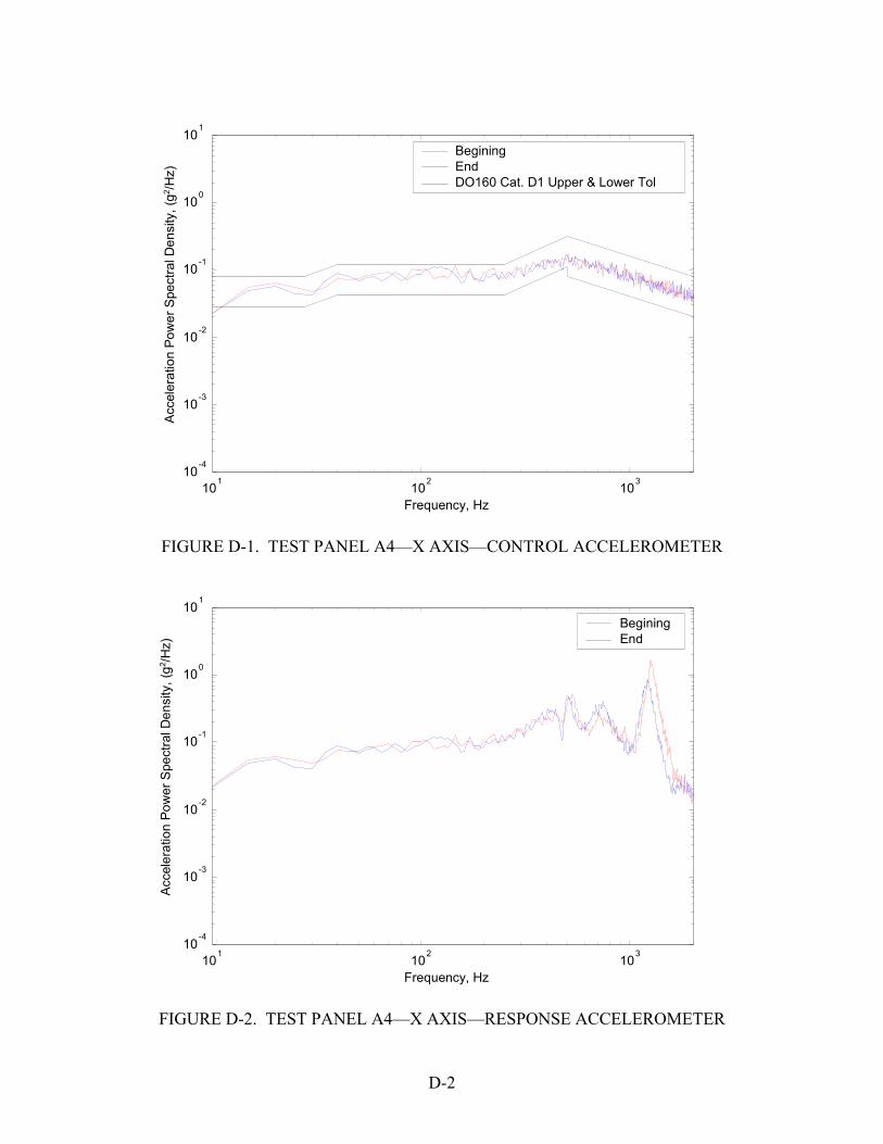
10 1 102
10 3 10 -4
10 -3
10 -2
10 -1
10 0
10 1
Frequency, Hz
Acc
eler
atio
n Po
wer
Spe
ctra
l Den
sity
, (g2 /H
z) Begining
End DO160 Cat. D1 Upper & Lower Tol
FIGURE D-1. TEST PANEL A4—X AXIS—CONTROL ACCELEROMETER
10 1 102
10 3 10 -4
10 -3
10 -2
10 -1
10 0
10 1
Frequency, Hz
Begining End
Acc
eler
atio
n Po
wer
Spe
ctra
l Den
sity
, (g2 /H
z)
FIGURE D-2. TEST PANEL A4—X AXIS—RESPONSE ACCELEROMETER
D-2

10 1 102
10 3 10 -4
10 -3
10 -2
10 -1
10 0
10 1
Frequency (Hz)
Begining End DO160 Cat. D1 Upper & Lower Tol
Acc
eler
atio
n Po
wer
Spe
ctra
l Den
sity
, (g2 /H
z)
FIGURE D-3. TEST PANEL A4—Y AXIS—CONTROL ACCELEROMETER
10 1 102
10 3 10 -4
10 -3
10 -2
10 -1
10 0
10 1
Frequency (Hz)
Begining End
Acc
eler
atio
n Po
wer
Spe
ctra
l Den
sity
, (g2 /H
z)
FIGURE D-4. TEST PANEL A4—Y AXIS—RESPONSE ACCELEROMETER
D-3
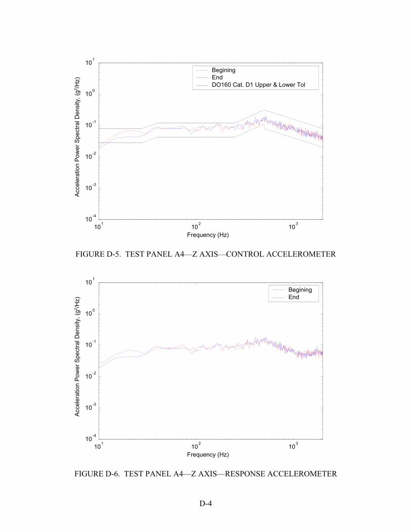
10 1 102
10 3 10 -4
10 -3
10 -2
10 -1
10 0
10 1
Frequency (Hz)
Begining End DO160 Cat. D1 Upper & Lower Tol
Acc
eler
atio
n Po
wer
Spe
ctra
l Den
sity
, (g2 /H
z)
FIGURE D-5. TEST PANEL A4—Z AXIS—CONTROL ACCELEROMETER
10 1 102
10 3 10 -4
10 -3
10 -2
10 -1
10 0
10 1
Frequency (Hz)
Begining End
Acc
eler
atio
n Po
wer
Spe
ctra
l Den
sity
, (g2 /H
z)
FIGURE D-6. TEST PANEL A4—Z AXIS—RESPONSE ACCELEROMETER
D-4

10 1 102
10 3 10 -4
10 -3
10 -2
10 -1
10 0
10 1
Frequency, Hz
Begining End DO160 Cat. D1 Upper & Lower Tol
Acc
eler
atio
n Po
wer
Spe
ctra
l Den
sity
, (g2 /H
z)
FIGURE D-7. TEST PANEL A5—X AXIS—CONTROL ACCELEROMETER
10 1 102
10 3 10 -4
10 -3
10 -2
10 -1
10 0
10 1
Frequency, Hz
Begining End
Acc
eler
atio
n Po
wer
Spe
ctra
l Den
sity
, (g2 /H
z)
FIGURE D-8. TEST PANEL A5—X AXIS—RESPONSE ACCELEROMETER
D-5
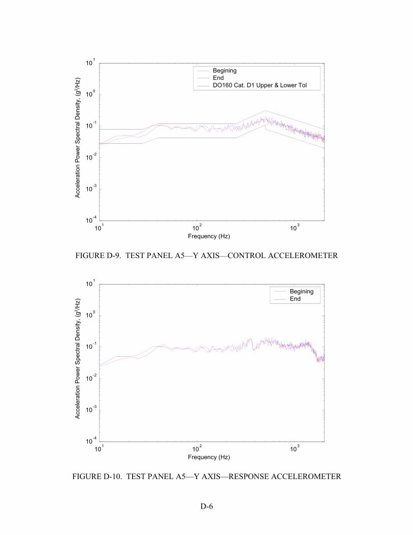
10 1 102
10 3 10 -4
10 -3
10 -2
10 -1
10 0
10 1
Frequency (Hz)
Begining End DO160 Cat. D1 Upper & Lower Tol
Acc
eler
atio
n Po
wer
Spe
ctra
l Den
sity
, (g2 /H
z)
FIGURE D-9. TEST PANEL A5—Y AXIS—CONTROL ACCELEROMETER
10 1 102
10 3 10 -4
10 -3
10 -2
10 -1
10 0
10 1
Frequency (Hz)
Begining End
Acc
eler
atio
n Po
wer
Spe
ctra
l Den
sity
, (g2 /H
z)
FIGURE D-10. TEST PANEL A5—Y AXIS—RESPONSE ACCELEROMETER
D-6

10 1 102
10 3 10 -4
10 -3
10 -2
10 -1
10 0
10 1
Frequency (Hz)
Begining End DO160 Cat. D1 Upper & Lower Tol
Acc
eler
atio
n Po
wer
Spe
ctra
l Den
sity
, (g2 /H
z)
FIGURE D-11. TEST PANEL A5—Z AXIS—CONTROL ACCELEROMETER
10 1 102
10 3 10 -4
10 -3
10 -2
10 -1
10 0
10 1
Frequency (Hz)
Begining End
Acc
eler
atio
n Po
wer
Spe
ctra
l Den
sity
, (g2 /H
z)
FIGURE D-12. TEST PANEL A5—Z AXIS—RESPONSE ACCELEROMETER
D-7/D-8