Embed Size (px)
Citation preview
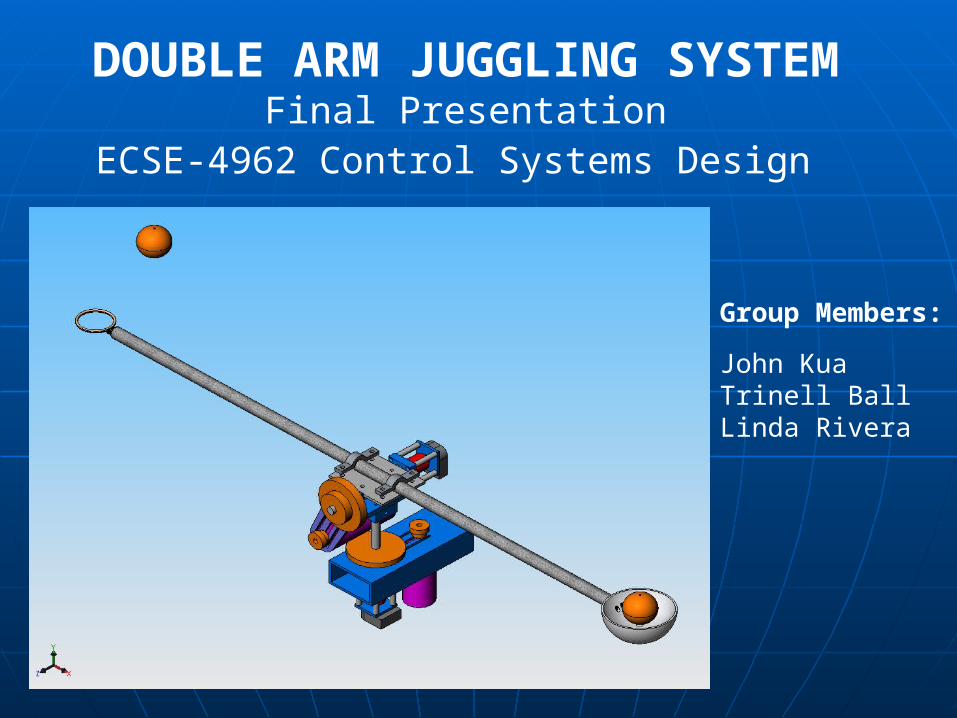
DOUBLE ARM JUGGLING SYSTEMFinal Presentation
ECSE-4962 Control Systems Design
Group Members:
John KuaTrinell BallLinda Rivera
Presentation OutlinePresentation Outline IntroductionIntroduction ObjectivesObjectives System SpecificationsSystem Specifications Plan of ActionPlan of Action System IntegrationSystem Integration Physical DesignPhysical Design ModelingModeling Control SystemControl System Camera DevelopmentCamera Development ResultsResults Future ImprovementsFuture Improvements
IntroductionIntroduction
Goal:Goal: To design and develop a To design and develop a juggling juggling system mechanism system mechanism• Pivoted double-ended armPivoted double-ended arm• Able to handle two or more ping pong Able to handle two or more ping pong
ballsballs
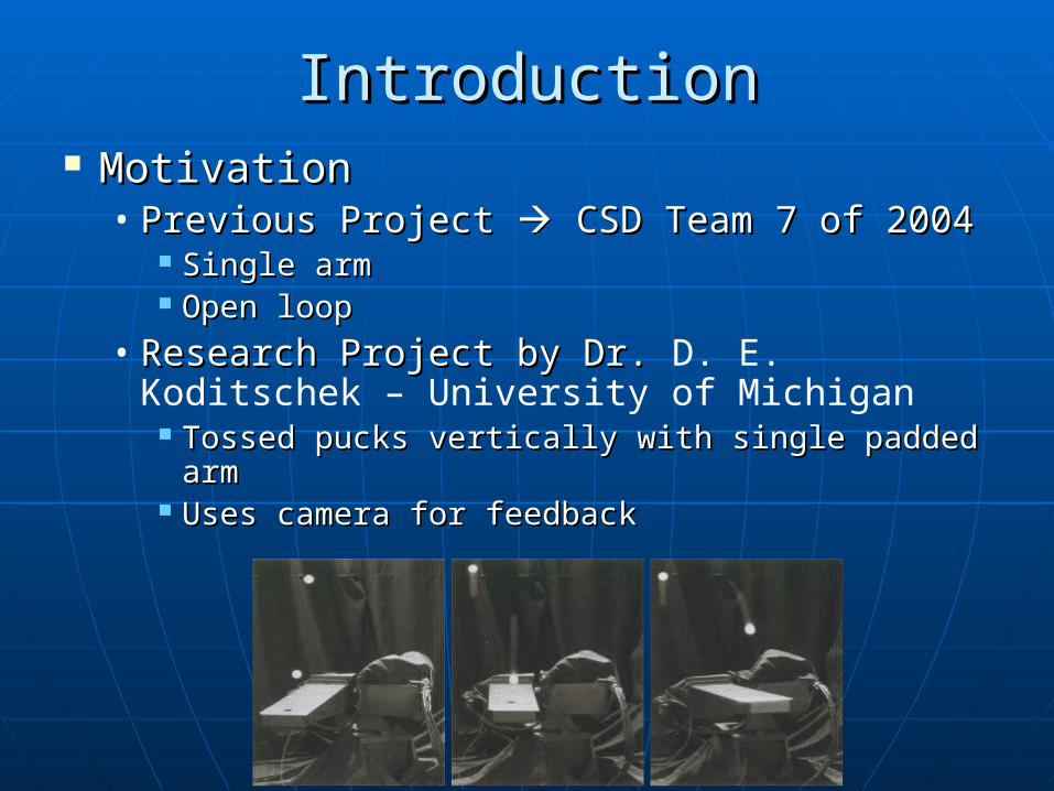
MotivationMotivation• Previous Project Previous Project CSD Team 7 of 2004 CSD Team 7 of 2004
Single armSingle arm Open loopOpen loop
• Research Project by Dr. Research Project by Dr. D. E. Koditschek – University of Michigan
Tossed pucks vertically with single padded arm Tossed pucks vertically with single padded arm Uses camera for feedbackUses camera for feedback
IntroductionIntroduction
ObjectivesObjectives
Develop mechanism to simultaneously juggle two or more balls• Execute toss and catch operations quickly • Provide feedback on arm’s state• Provide feedback on balls’ state
Predict trajectory of the ball
• Design control system Learn from toss/catch errors Compensate for disturbances in flight path
of the balls
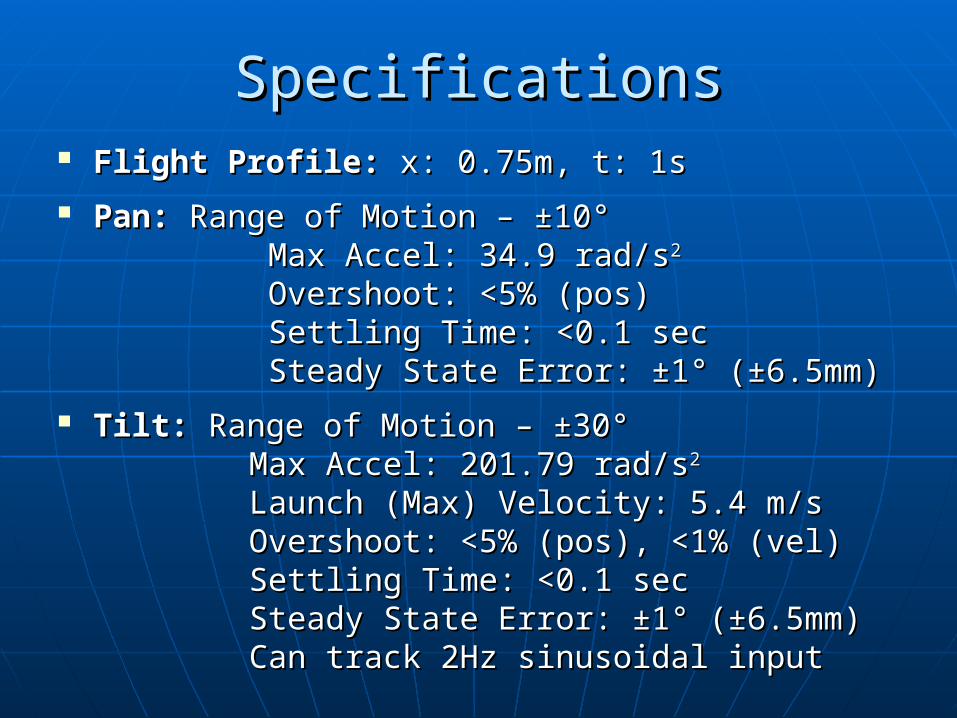
SpecificationsSpecifications Flight Profile:Flight Profile: x: 0.75m, t: 1s x: 0.75m, t: 1s Pan:Pan: Range of Motion – ±10° Range of Motion – ±10° Max Accel: 34.9 rad/sMax Accel: 34.9 rad/s22
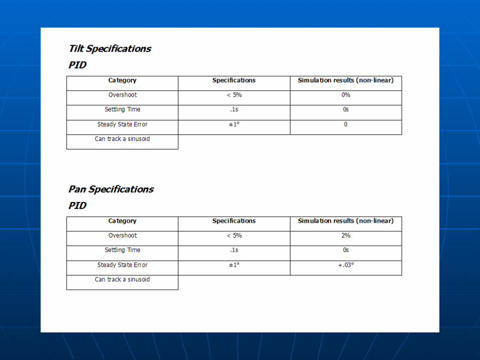
Overshoot: <5% (pos)Overshoot: <5% (pos) Settling Time: <0.1 secSettling Time: <0.1 sec Steady State Error: ±1° (±6.5mm)Steady State Error: ±1° (±6.5mm) Tilt:Tilt: Range of Motion – ±30° Range of Motion – ±30° Max Accel: 201.79 rad/sMax Accel: 201.79 rad/s22
Launch (Max) Velocity: 5.4 m/sLaunch (Max) Velocity: 5.4 m/s Overshoot: <5% (pos), <1% (vel)Overshoot: <5% (pos), <1% (vel) Settling Time: <0.1 secSettling Time: <0.1 sec Steady State Error: ±1° (±6.5mm)Steady State Error: ±1° (±6.5mm) Can track 2Hz sinusoidal inputCan track 2Hz sinusoidal input
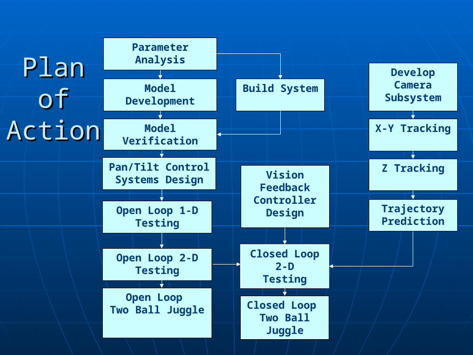
Model Development
Model Verification
Parameter Analysis
Build System
Develop Camera
Subsystem
X-Y Tracking
Z Tracking
Trajectory Prediction
Pan/Tilt Control Systems Design
Open Loop 1-DTesting
Open Loop 2-DTesting
Open Loop Two Ball Juggle
Closed Loop 2-D
Testing
Closed Loop Two Ball Juggle
Vision Feedback Controller
Design
PlanPlanofof
ActionAction
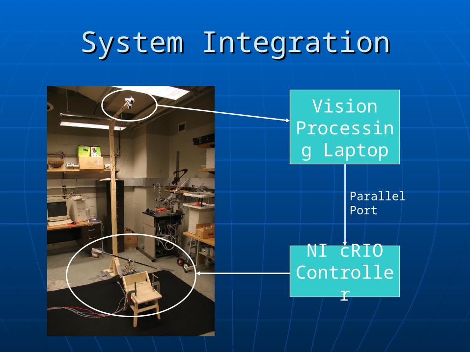
System IntegrationSystem Integration
Vision Processing
Laptop
NI cRIO Controller
Parallel Port
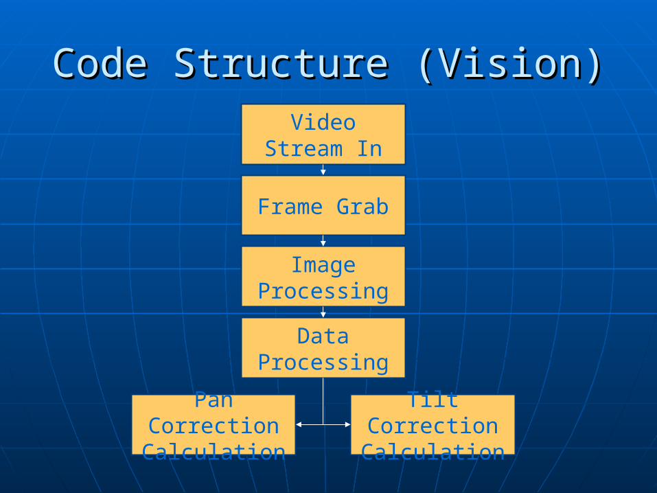
Code Structure (Vision)Code Structure (Vision)
Pan Correction Calculation
Video Stream In
Image Processing
Frame Grab
Data Processing
Tilt Correction Calculation
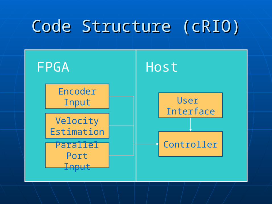
Code Structure (cRIO)Code Structure (cRIO)
HostFPGA
Controller
EncoderInput
Parallel PortInput
Velocity Estimation
User Interface
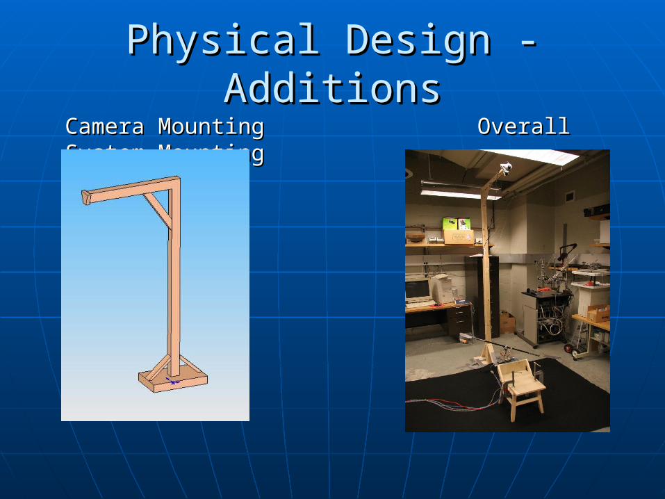
Camera Camera Mounting Mounting Overall System Overall System MountingMounting
Physical Design - AdditionsPhysical Design - Additions
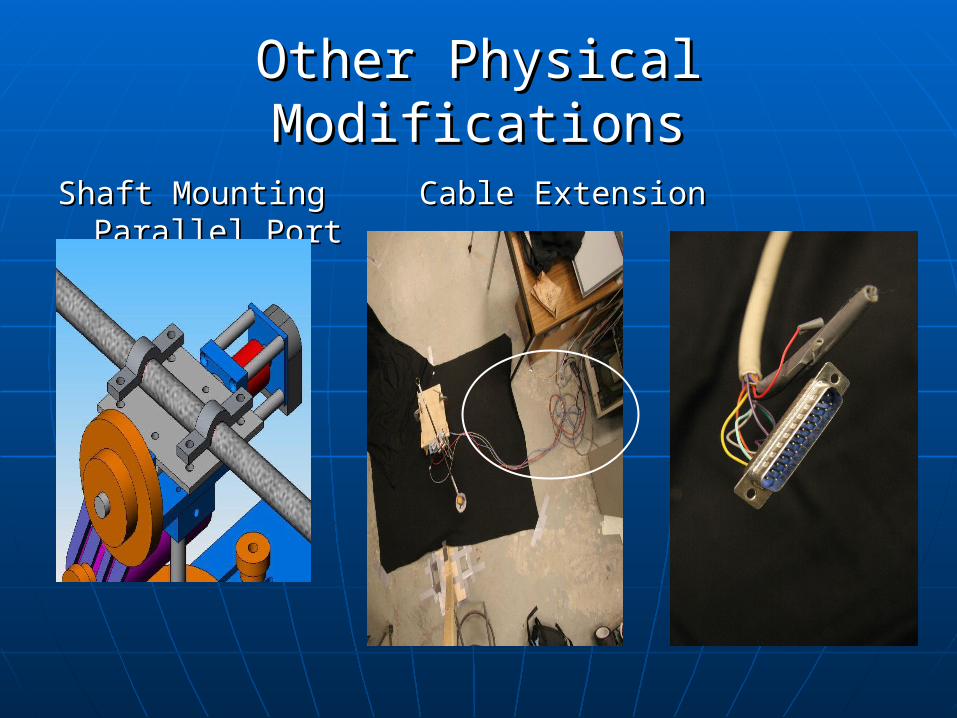
Other Physical ModificationsOther Physical Modifications
Shaft MountingShaft Mounting Cable Extension Parallel Cable Extension Parallel PortPort
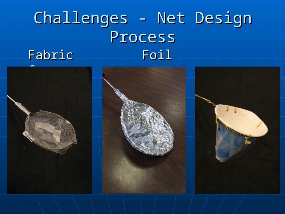
Challenges - Net Design Challenges - Net Design ProcessProcess
FabricFabric FoilFoil Cones Cones
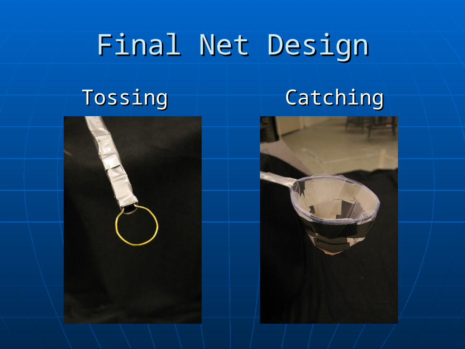
Final Net DesignFinal Net Design
TossingTossing CatchingCatching
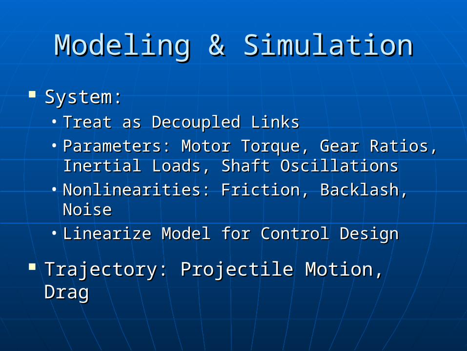
Modeling & SimulationModeling & Simulation
System:System:• Treat as Decoupled LinksTreat as Decoupled Links• Parameters: Motor Torque, Gear Ratios, Parameters: Motor Torque, Gear Ratios,
Inertial Loads, Shaft OscillationsInertial Loads, Shaft Oscillations• Nonlinearities: Friction, Backlash, NoiseNonlinearities: Friction, Backlash, Noise• Linearize Model for Control DesignLinearize Model for Control Design
Trajectory: Projectile Motion, DragTrajectory: Projectile Motion, Drag
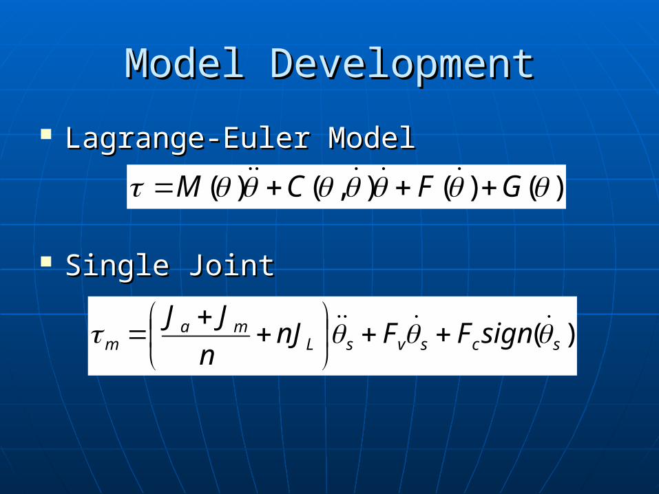
Model DevelopmentModel Development
Lagrange-Euler ModelLagrange-Euler Model
Single JointSingle Joint
)()(),()( GFCM
)( scsvsLma
m signFFnJn
JJ
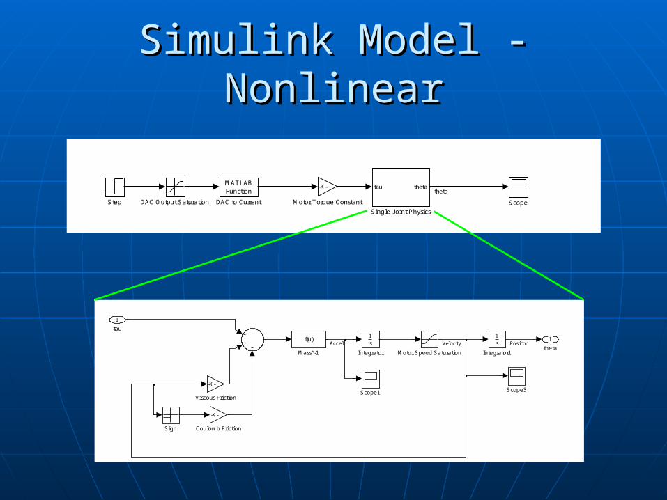
Simulink Model - NonlinearSimulink Model - Nonlinear
1
theta
-K-
Viscous Friction
Sign
Scope3Scope1
Motor Speed Saturation
f(u)
Mass -1
1s
Integrator1
1s
Integrator
-K-
Coulomb Friction
1
tau
Accel PositionVelocity
Step
tau theta
Single Joint Physics
Scope
-K-
Motor Torque Constant
MATLABFunction
DAC to CurrentDAC Output Saturation
theta
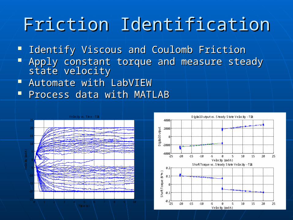
Friction IdentificationFriction Identification Identify Viscous and Coulomb FrictionIdentify Viscous and Coulomb Friction Apply constant torque and measure steady state Apply constant torque and measure steady state
velocityvelocity Automate with LabVIEWAutomate with LabVIEW Process data with MATLABProcess data with MATLAB
0 1 2 3 4 5 6 7 8 9 10-25
-20
-15
-10
-5
0
5
10
15
20
25Velocity vs. Time - Tilt
Time (s)
Vel
ocity
(ra
d/s)
-25 -20 -15 -10 -5 0 5 10 15 20 25-4000
-2000
0
2000
4000Digital Output vs. Steady State Velocity - Tilt
Dig
ital O
utpu
tVelocity (rad/s)
-25 -20 -15 -10 -5 0 5 10 15 20 25-0.2
-0.1
0
0.1
0.2Shaft Torque vs. Steady State Velocity - Tilt
Sha
ft T
orqu
e (N
*m)
Velocity (rad/s)
Other ParametersOther Parameters
Inertia/MassInertia/Mass• Calculated with SolidWorksCalculated with SolidWorks
Shaft Spring ConstantShaft Spring Constant• Possible cause of oscillationsPossible cause of oscillations• Experimentally measuredExperimentally measured• Found to be very stiff - k=4600N/m Found to be very stiff - k=4600N/m
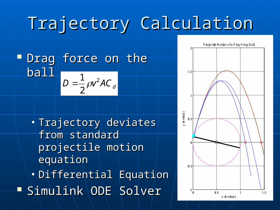
Trajectory CalculationTrajectory Calculation
Drag force on the ballDrag force on the ball
• Trajectory deviates Trajectory deviates from standard from standard projectile motion projectile motion equationequation
• Differential EquationDifferential Equation Simulink ODE SolverSimulink ODE Solver
0 0.5 1 1.5-1
-0.5
0
0.5
1
1.5
2Projectile Motion of a Ping Pong Ball
x (meters)
y (m
eter
s)
dACvD 2
2
1
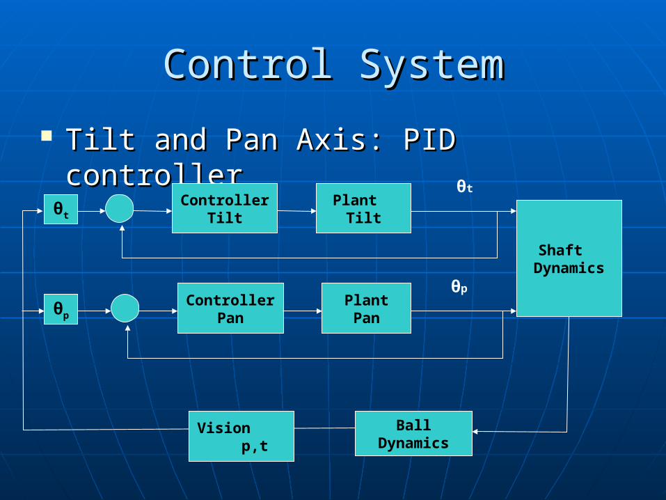
Control SystemControl System
Tilt and Pan Axis: PID controller Tilt and Pan Axis: PID controller
Controller Tilt
Plant Tilt
θt
Controller Pan
Plant Pan
θp
Shaft Dynamics
Ball Dynamics
Vision p,t
θp
θt
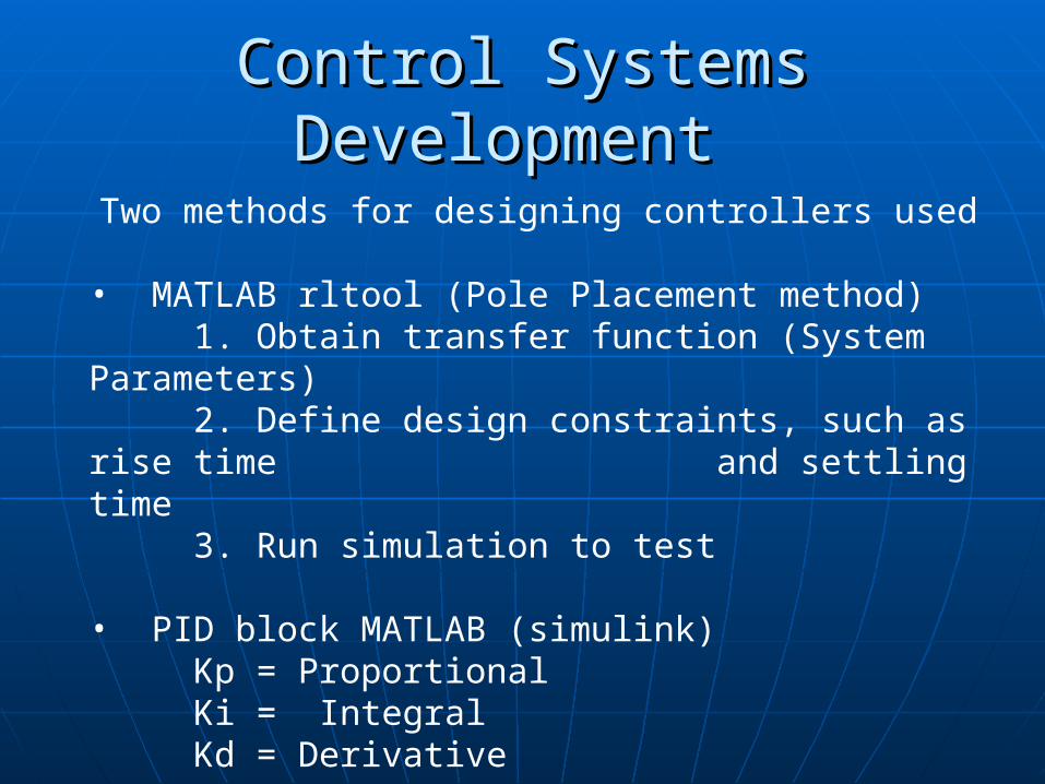
Control Systems Control Systems DevelopmentDevelopment
Two methods for designing controllers used • MATLAB rltool (Pole Placement method)
1. Obtain transfer function (System Parameters)
2. Define design constraints, such as rise time and settling time
3. Run simulation to test • PID block MATLAB (simulink)
Kp = Proportional Ki = IntegralKd = Derivative
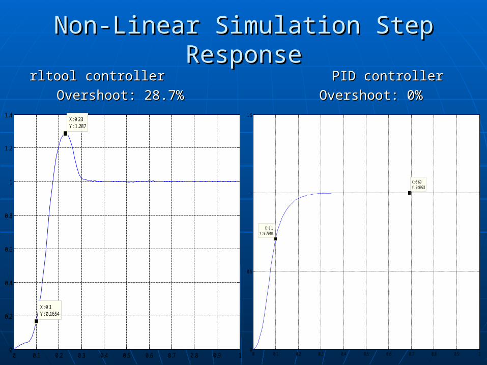
rltool controller PID controllerrltool controller PID controller
Overshoot: 28.7% Overshoot: 0%Overshoot: 28.7% Overshoot: 0%
0 0.1 0.2 0.3 0.4 0.5 0.6 0.7 0.8 0.9 10
0.2
0.4
0.6
0.8
1
1.2
1.4
X: 0.1Y: 0.1654
X: 0.23Y: 1.287
0 0.1 0.2 0.3 0.4 0.5 0.6 0.7 0.8 0.9 10
0.5
1
1.5
X: 0.1Y: 0.7048
X: 0.69Y: 0.9993
Non-Linear Simulation Step Non-Linear Simulation Step ResponseResponse
Camera DevelopmentCamera Development
Image ProcessingImage Processing Data VerificationData Verification Trajectory PredictionTrajectory Prediction
• PanPan• TiltTilt
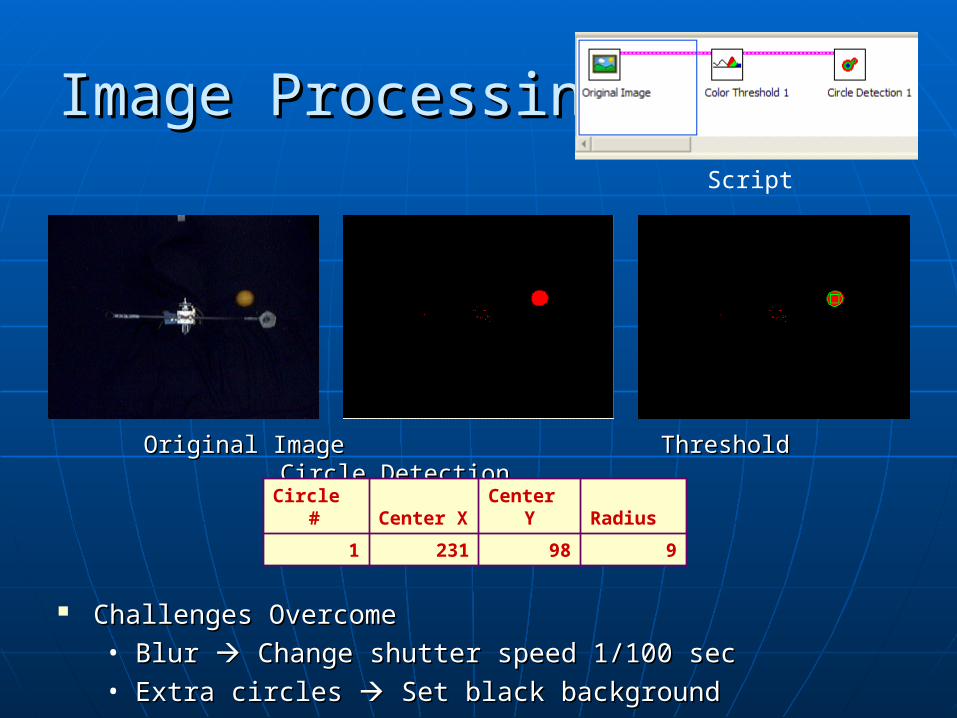
Original Image Threshold Circle Original Image Threshold Circle DetectionDetection
Challenges OvercomeChallenges Overcome• Blur Blur Change shutter speed 1/100 sec Change shutter speed 1/100 sec• Extra circles Extra circles Set black background Set black background
Circle # Center X Center Y Radius
1 231 98 9
Image ProcessingImage ProcessingScript
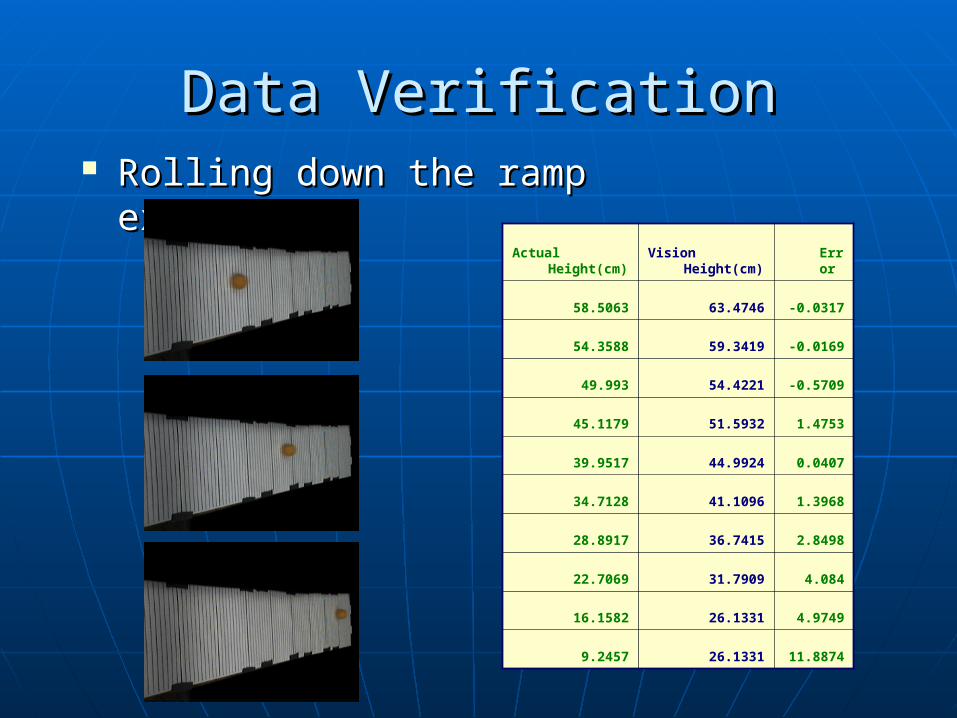
Rolling down the ramp Rolling down the ramp experimentexperiment
Actual Height(cm) Vision Height(cm) Error
58.5063 63.4746 -0.0317
54.3588 59.3419 -0.0169
49.993 54.4221 -0.5709
45.1179 51.5932 1.4753
39.9517 44.9924 0.0407
34.7128 41.1096 1.3968
28.8917 36.7415 2.8498
22.7069 31.7909 4.084
16.1582 26.1331 4.9749
9.2457 26.1331 11.8874
Data VerificationData Verification
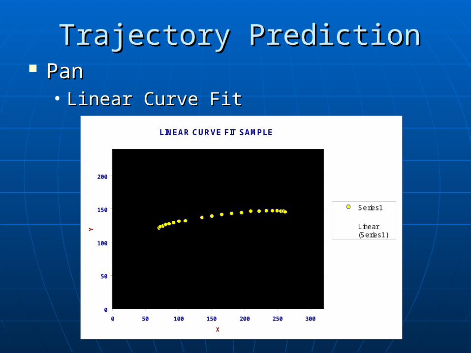
PanPan• Linear Curve FitLinear Curve Fit
LINEAR CURVE FIT SAMPLE
0
50
100
150
200
0 50 100 150 200 250 300
X
Y
Series1
Linear(Series1)
Trajectory PredictionTrajectory Prediction
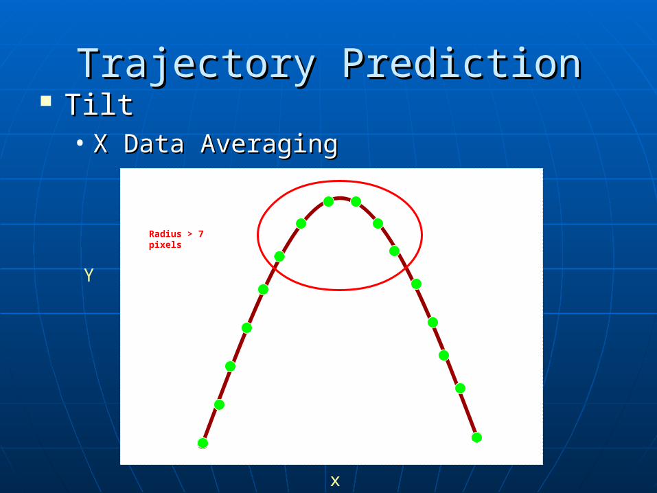
TiltTilt• X Data AveragingX Data Averaging
x
Y
Radius > 7 pixels
Trajectory PredictionTrajectory Prediction
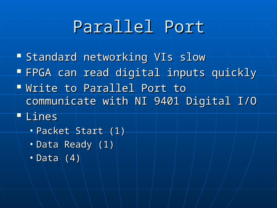
Parallel PortParallel Port
Standard networking VIs slowStandard networking VIs slow FPGA can read digital inputs quicklyFPGA can read digital inputs quickly Write to Parallel Port to communicate Write to Parallel Port to communicate
with NI 9401 Digital I/Owith NI 9401 Digital I/O LinesLines
• Packet Start (1)Packet Start (1)• Data Ready (1)Data Ready (1)• Data (4)Data (4)
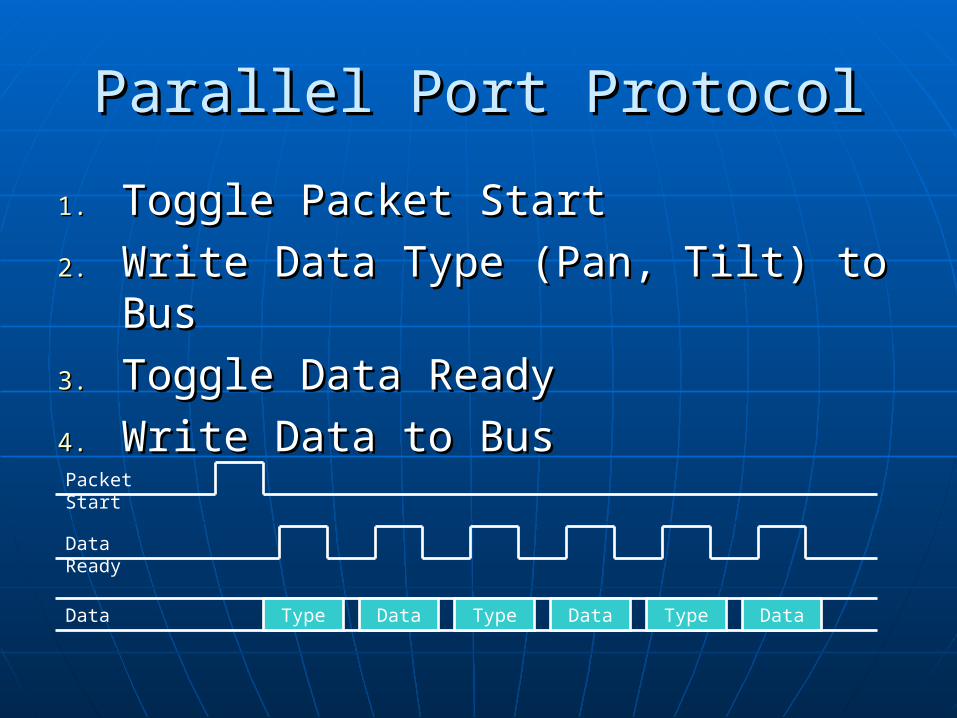
Parallel Port ProtocolParallel Port Protocol
1.1. Toggle Packet StartToggle Packet Start
2.2. Write Data Type (Pan, Tilt) to BusWrite Data Type (Pan, Tilt) to Bus
3.3. Toggle Data ReadyToggle Data Ready
4.4. Write Data to BusWrite Data to Bus
Type
Data Type
Data Type
Data
Packet Start
Data Ready
Data
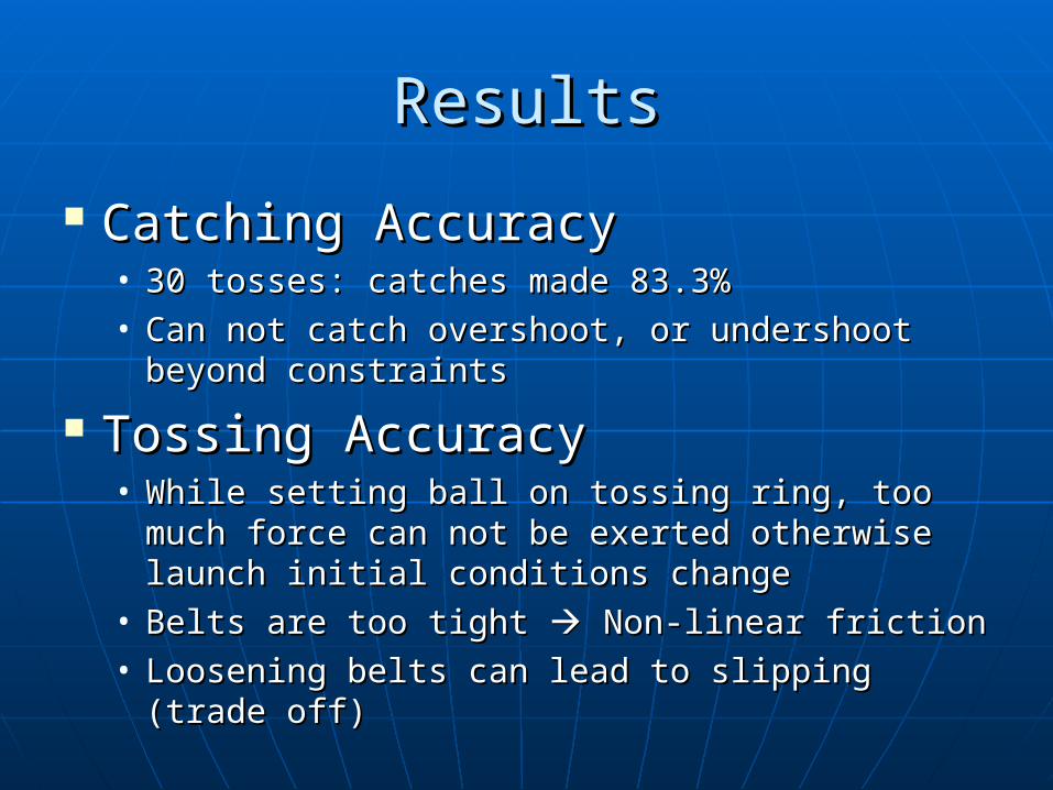
ResultsResults
Catching AccuracyCatching Accuracy• 30 tosses: catches made 83.3%30 tosses: catches made 83.3%• Can not catch overshoot, or undershoot Can not catch overshoot, or undershoot
beyond constraintsbeyond constraints
Tossing AccuracyTossing Accuracy• While setting ball on tossing ring, too much While setting ball on tossing ring, too much
force can not be exerted otherwise launch force can not be exerted otherwise launch initial conditions changeinitial conditions change
• Belts are too tight Belts are too tight Non-linear friction Non-linear friction• Loosening belts can lead to slipping (trade off)Loosening belts can lead to slipping (trade off)
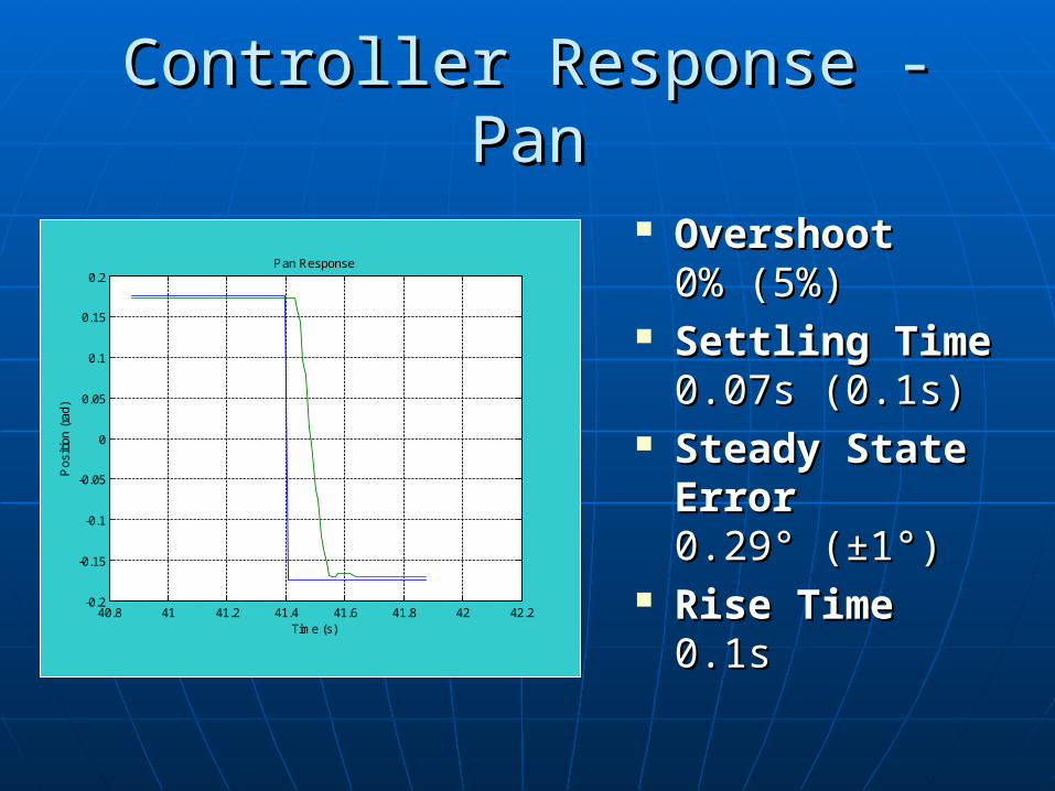
Controller Response - PanController Response - Pan
40.8 41 41.2 41.4 41.6 41.8 42 42.2-0.2
-0.15
-0.1
-0.05
0
0.05
0.1
0.15
0.2Pan Response
Time (s)
Pos
ition
(ra
d)
OvershootOvershoot 0% (5%)0% (5%)
Settling TimeSettling Time 0.07s (0.1s)0.07s (0.1s)
Steady State Steady State Error Error 0.29° (±1°)0.29° (±1°)
Rise TimeRise Time0.1s0.1s
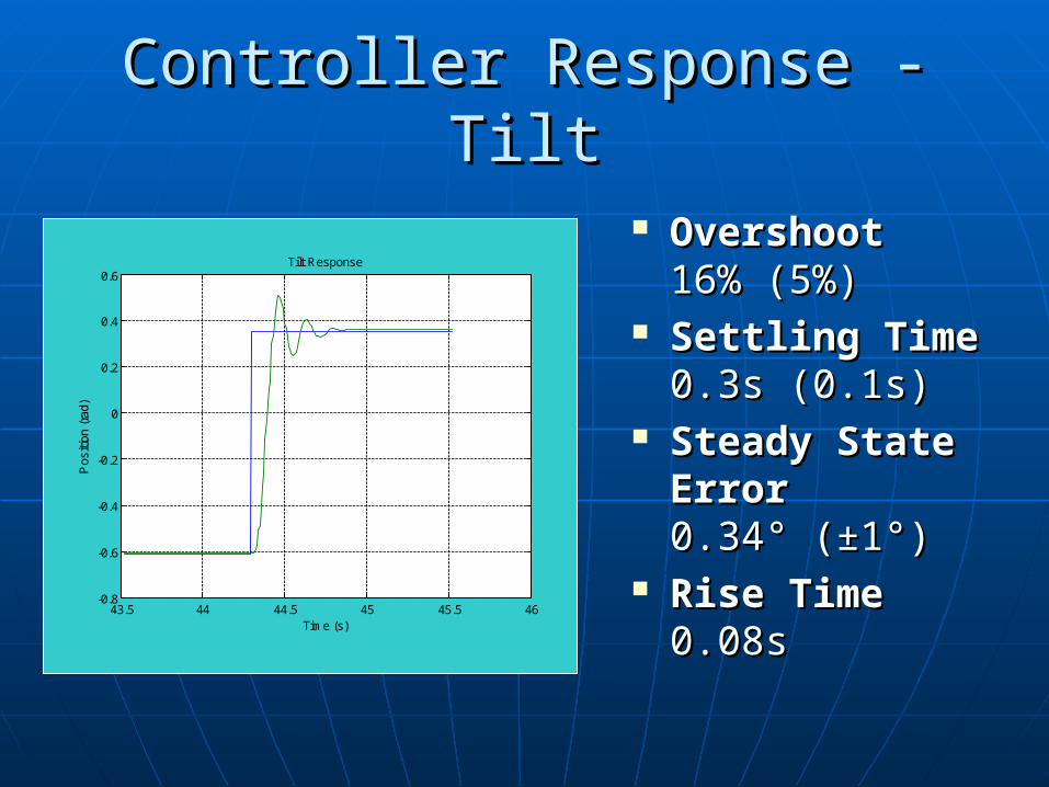
Controller Response - TiltController Response - Tilt
OvershootOvershoot 16% (5%)16% (5%)
Settling TimeSettling Time 0.3s (0.1s)0.3s (0.1s)
Steady State Steady State Error Error 0.34° (±1°) 0.34° (±1°)
Rise TimeRise Time0.08s0.08s
43.5 44 44.5 45 45.5 46-0.8
-0.6
-0.4
-0.2
0
0.2
0.4
0.6Tilt Response
Time (s)
Pos
ition
(ra
d)

VideoVideo
Play Video HerePlay Video Here
Future ImprovementsFuture Improvements Implement Trajectory GenerationImplement Trajectory Generation Better Controller (LQR)Better Controller (LQR) Improve Height EstimationImprove Height Estimation
• Add second cameraAdd second camera• Increase camera resolution (processing power)Increase camera resolution (processing power)
Better way to transfer torque from motor Better way to transfer torque from motor to pan tilt joints other than existing beltsto pan tilt joints other than existing belts
JugglingJuggling• System response not fast enoughSystem response not fast enough• Nets need dual-use optimizationNets need dual-use optimization