Embed Size (px)
Citation preview
DoubleSideCooledModule
FF400R07A01E3_S6
FinalDataSheetV3.3,2017-07-28
AutomotiveHighPower
2
FF400R07A01E3_S6DoubleSideCooledModule
V3.3,2017-07-28Final Data Sheet
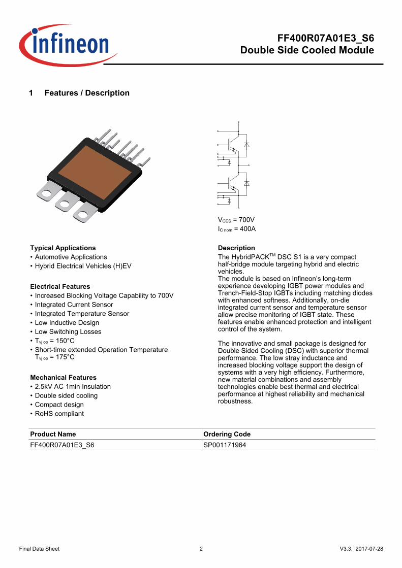
1Features/Description
VCES = 700VIC nom = 400A
TypicalApplications DescriptionThe HybridPACKTM DSC S1 is a very compacthalf-bridge module targeting hybrid and electricvehicles.The module is based on Infineon’s long-termexperience developing IGBT power modules andTrench-Field-Stop IGBTs including matching diodeswith enhanced softness. Additionally, on-dieintegrated current sensor and temperature sensorallow precise monitoring of IGBT state. Thesefeatures enable enhanced protection and intelligentcontrol of the system.
The innovative and small package is designed forDouble Sided Cooling (DSC) with superior thermalperformance. The low stray inductance andincreased blocking voltage support the design ofsystems with a very high efficiency. Furthermore,new material combinations and assemblytechnologies enable best thermal and electricalperformance at highest reliability and mechanicalrobustness.
• AutomotiveApplications• HybridElectricalVehicles(H)EV
ElectricalFeatures• IncreasedBlockingVoltageCapabilityto700V• IntegratedCurrentSensor• IntegratedTemperatureSensor• LowInductiveDesign• LowSwitchingLosses• Tvjop=150°C• Short-time extended Operation Temperature Tvjop=175°C
MechanicalFeatures• 2.5kVAC1minInsulation• Doublesidedcooling• Compactdesign• RoHScompliant
ProductName OrderingCodeFF400R07A01E3_S6 SP001171964
3
FF400R07A01E3_S6DoubleSideCooledModule
V3.3,2017-07-28Final Data Sheet
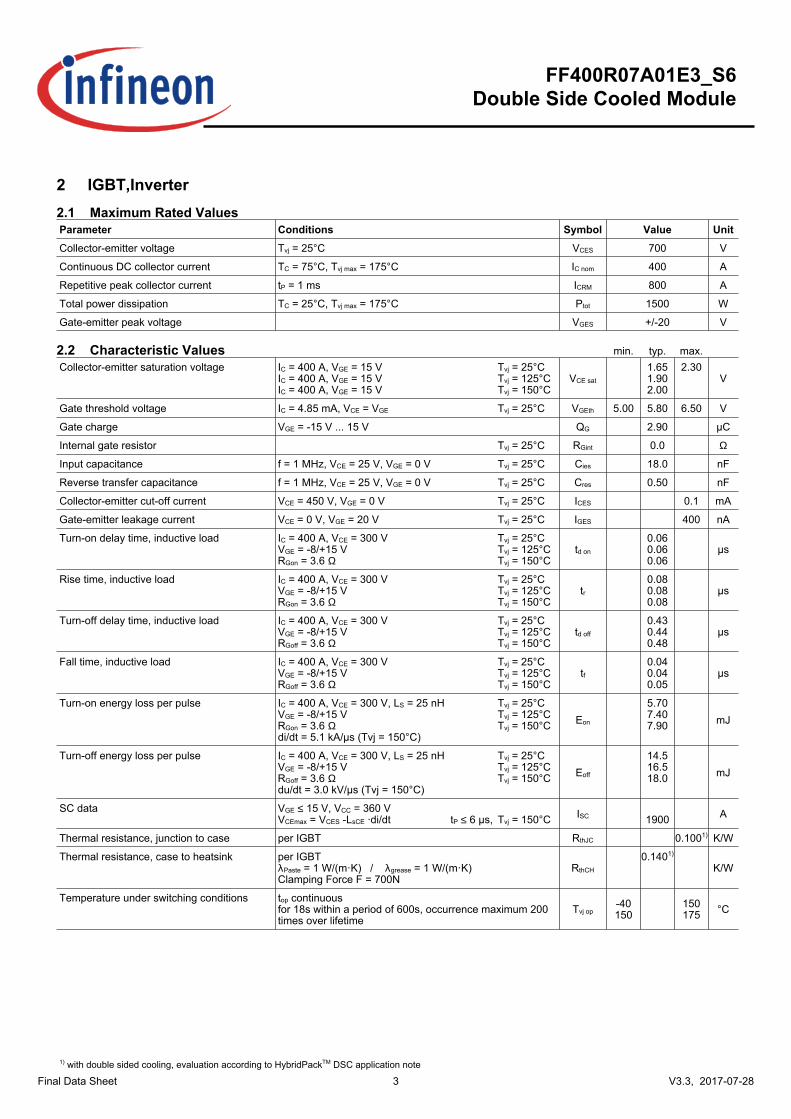
2IGBT,Inverter2.1MaximumRatedValuesParameter Conditions Symbol Value UnitCollector-emittervoltage Tvj = 25°C VCES 700 V
ContinuousDCcollectorcurrent TC = 75°C, Tvj max = 175°C IC nom 400 A
Repetitivepeakcollectorcurrent tP = 1 ms ICRM 800 A
Totalpowerdissipation TC = 25°C, Tvj max = 175°C Ptot 1500 W
Gate-emitterpeakvoltage VGES +/-20 V
2.2CharacteristicValues min. typ. max.
Collector-emittersaturationvoltage IC = 400 A, VGE = 15 VIC = 400 A, VGE = 15 VIC = 400 A, VGE = 15 V
VCE sat
1.651.902.00
2.30V
Tvj = 25°CTvj = 125°CTvj = 150°C
Gatethresholdvoltage IC = 4.85 mA, VCE = VGE VGEth 5.00 5.80 6.50 VTvj = 25°C
Gatecharge VGE = -15 V ... 15 V QG 2.90 µC
Internalgateresistor RGint 0.0 ΩTvj = 25°C
Inputcapacitance f = 1 MHz, VCE = 25 V, VGE = 0 V Cies 18.0 nFTvj = 25°C
Reversetransfercapacitance f = 1 MHz, VCE = 25 V, VGE = 0 V Cres 0.50 nFTvj = 25°C
Collector-emittercut-offcurrent VCE = 450 V, VGE = 0 V ICES 0.1 mATvj = 25°C
Gate-emitterleakagecurrent VCE = 0 V, VGE = 20 V IGES 400 nATvj = 25°C
Turn-ondelaytime,inductiveload IC = 400 A, VCE = 300 VVGE = -8/+15 VRGon = 3.6 Ω
td on
0.060.060.06
µsTvj = 25°CTvj = 125°CTvj = 150°C
Risetime,inductiveload IC = 400 A, VCE = 300 VVGE = -8/+15 VRGon = 3.6 Ω
tr0.080.080.08
µsTvj = 25°CTvj = 125°CTvj = 150°C
Turn-offdelaytime,inductiveload IC = 400 A, VCE = 300 VVGE = -8/+15 VRGoff = 3.6 Ω
td off
0.430.440.48
µsTvj = 25°CTvj = 125°CTvj = 150°C
Falltime,inductiveload IC = 400 A, VCE = 300 VVGE = -8/+15 VRGoff = 3.6 Ω
tf0.040.040.05
µsTvj = 25°CTvj = 125°CTvj = 150°C
Turn-onenergylossperpulse IC = 400 A, VCE = 300 V, LS = 25 nHVGE = -8/+15 VRGon = 3.6 Ωdi/dt = 5.1 kA/µs (Tvj = 150°C)
Eon
5.707.407.90 mJ
Tvj = 25°CTvj = 125°CTvj = 150°C
Turn-offenergylossperpulse IC = 400 A, VCE = 300 V, LS = 25 nHVGE = -8/+15 VRGoff = 3.6 Ωdu/dt = 3.0 kV/µs (Tvj = 150°C)
Eoff
14.516.518.0 mJ
Tvj = 25°CTvj = 125°CTvj = 150°C
SCdata VGE ≤ 15 V, VCC = 360 VVCEmax = VCES -LsCE ·di/dt ISC 1900 A
Tvj = 150°C tP ≤ 6 µs,
Thermalresistance,junctiontocase perIGBT RthJC 0.1001) K/W
Thermalresistance,casetoheatsink perIGBTλPaste=1W/(m·K)/λgrease=1W/(m·K)ClampingForceF=700N
RthCH
0.1401)
K/W
Temperatureunderswitchingconditions top continuousfor 18s within a period of 600s, occurrence maximum 200times over lifetime
Tvj op-40150
150175 °C
1) with double sided cooling, evaluation according to HybridPackTM DSC application note
4
FF400R07A01E3_S6DoubleSideCooledModule
V3.3,2017-07-28Final Data Sheet
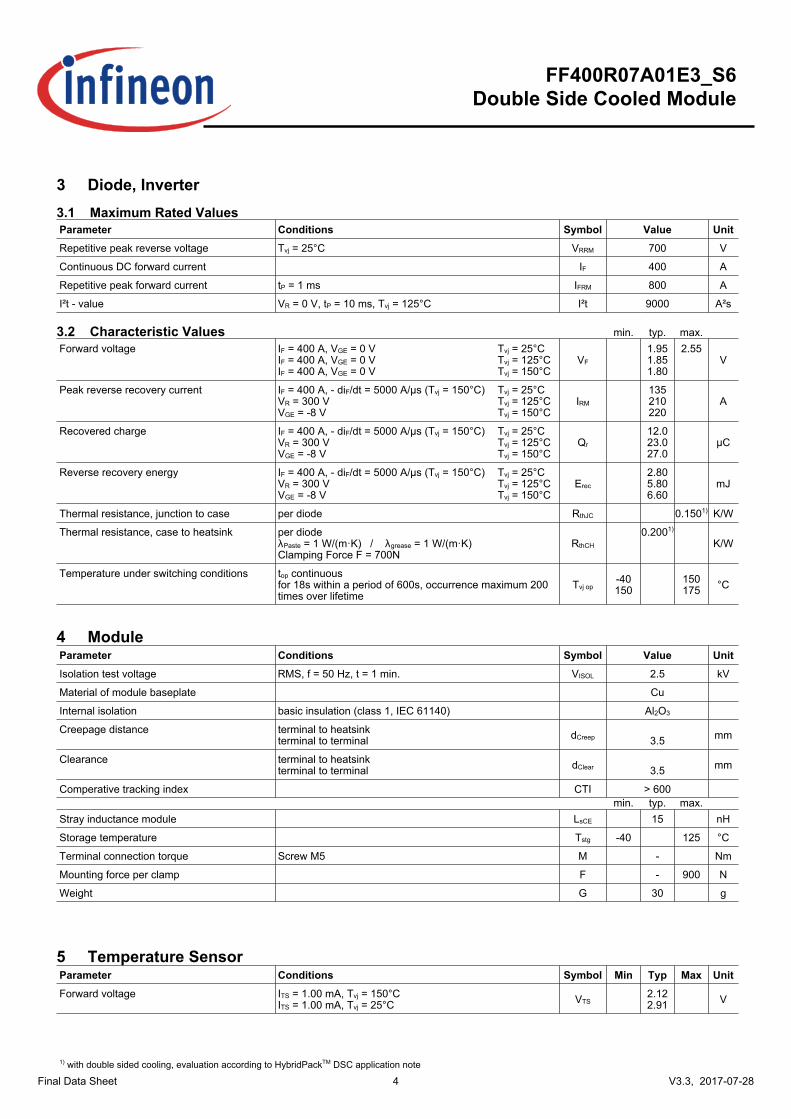
3Diode,Inverter3.1MaximumRatedValuesParameter Conditions Symbol Value UnitRepetitivepeakreversevoltage Tvj = 25°C VRRM 700 V
ContinuousDCforwardcurrent IF 400 A
Repetitivepeakforwardcurrent tP = 1 ms IFRM 800 A
I²t-value VR = 0 V, tP = 10 ms, Tvj = 125°C I²t 9000 A²s
3.2CharacteristicValues min. typ. max.
Forwardvoltage IF = 400 A, VGE = 0 VIF = 400 A, VGE = 0 VIF = 400 A, VGE = 0 V
VF
1.951.851.80
2.55V
Tvj = 25°CTvj = 125°CTvj = 150°C
Peakreverserecoverycurrent IF = 400 A, - diF/dt = 5000 A/µs (Tvj = 150°C)VR = 300 VVGE = -8 V
IRM
135210220
ATvj = 25°CTvj = 125°CTvj = 150°C
Recoveredcharge IF = 400 A, - diF/dt = 5000 A/µs (Tvj = 150°C)VR = 300 VVGE = -8 V
Qr
12.023.027.0
µCTvj = 25°CTvj = 125°CTvj = 150°C
Reverserecoveryenergy IF = 400 A, - diF/dt = 5000 A/µs (Tvj = 150°C)VR = 300 VVGE = -8 V
Erec
2.805.806.60
mJTvj = 25°CTvj = 125°CTvj = 150°C
Thermalresistance,junctiontocase perdiode RthJC 0.1501) K/W
Thermalresistance,casetoheatsink perdiodeλPaste=1W/(m·K)/λgrease=1W/(m·K)ClampingForceF=700N
RthCH
0.2001)
K/W
Temperatureunderswitchingconditions top continuousfor 18s within a period of 600s, occurrence maximum 200times over lifetime
Tvj op-40150
150175 °C
4ModuleParameter Conditions Symbol Value UnitIsolationtestvoltage RMS, f = 50 Hz, t = 1 min. VISOL 2.5 kV
Materialofmodulebaseplate Cu
Internalisolation basicinsulation(class1,IEC61140) Al2O3
Creepagedistance terminaltoheatsinkterminaltoterminal dCreep 3.5 mm
Clearance terminaltoheatsinkterminaltoterminal dClear 3.5 mm
Comperativetrackingindex CTI > 600 min. typ. max.
Strayinductancemodule LsCE 15 nH
Storagetemperature Tstg -40 125 °C
Terminalconnectiontorque ScrewM5 M - Nm
Mounting force per clamp F - 900 N
Weight G 30 g
5TemperatureSensorParameter Conditions Symbol Min Typ Max UnitForwardvoltage ITS = 1.00 mA, Tvj = 150°C
ITS = 1.00 mA, Tvj = 25°C VTS2.122.91 V
1) with double sided cooling, evaluation according to HybridPackTM DSC application note

5
FF400R07A01E3_S6DoubleSideCooledModule
V3.3,2017-07-28Final Data Sheet
6CurrentSensorParameter Conditions Symbol Min Typ Max UnitOutputvoltage VCE = 2.35 V, IC = 800 A
Rsense = 1.60 Ω, Tvj = 25°CVGE = 15 V
Vsense 0.64 V
6
FF400R07A01E3_S6DoubleSideCooledModule
V3.3,2017-07-28Final Data Sheet
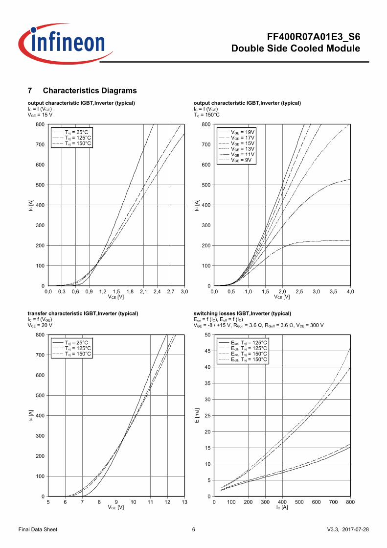
7CharacteristicsDiagramsoutputcharacteristicIGBT,Inverter(typical)IC=f(VCE)VGE=15V
VCE [V]
IC [A
]
0,0 0,3 0,6 0,9 1,2 1,5 1,8 2,1 2,4 2,7 3,00
100
200
300
400
500
600
700
800Tvj = 25°CTvj = 125°CTvj = 150°C
outputcharacteristicIGBT,Inverter(typical)IC=f(VCE)Tvj=150°C
VCE [V]
IC [A
]
0,0 0,5 1,0 1,5 2,0 2,5 3,0 3,5 4,00
100
200
300
400
500
600
700
800VGE = 19VVGE = 17VVGE = 15VVGE = 13VVGE = 11VVGE = 9V
transfercharacteristicIGBT,Inverter(typical)IC=f(VGE)VCE=20V
VGE [V]
IC [A
]
5 6 7 8 9 10 11 12 130
100
200
300
400
500
600
700
800Tvj = 25°CTvj = 125°CTvj = 150°C
switchinglossesIGBT,Inverter(typical)Eon=f(IC),Eoff=f(IC)VGE=-8/+15V,RGon=3.6Ω,RGoff=3.6Ω,VCE=300V
IC [A]
E [m
J]
0 100 200 300 400 500 600 700 8000
5
10
15
20
25
30
35
40
45
50Eon, Tvj = 125°CEoff, Tvj = 125°CEon, Tvj = 150°CEoff, Tvj = 150°C
7
FF400R07A01E3_S6DoubleSideCooledModule
V3.3,2017-07-28Final Data Sheet
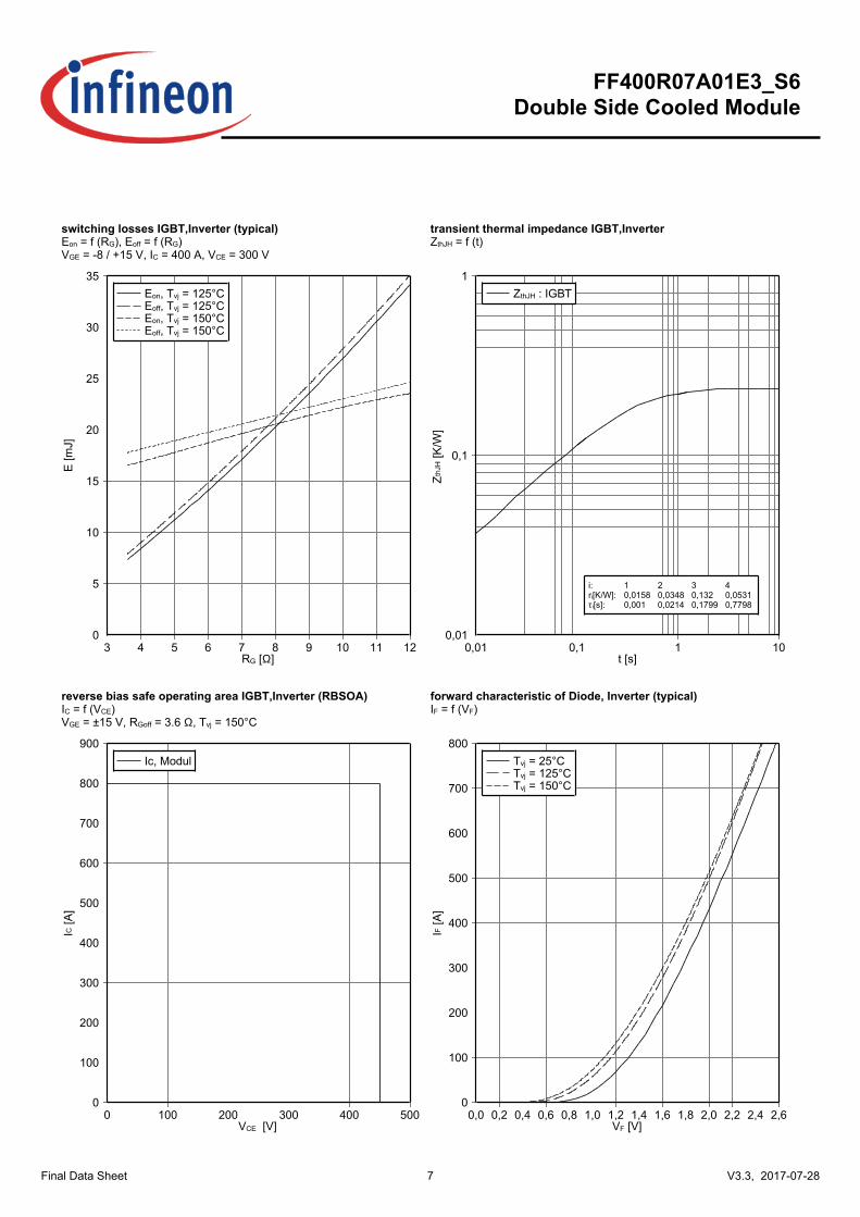
switchinglossesIGBT,Inverter(typical)Eon=f(RG),Eoff=f(RG)VGE=-8/+15V,IC=400A,VCE=300V
RG [Ω]
E [m
J]
3 4 5 6 7 8 9 10 11 120
5
10
15
20
25
30
35Eon, Tvj = 125°CEoff, Tvj = 125°CEon, Tvj = 150°CEoff, Tvj = 150°C
transientthermalimpedanceIGBT,InverterZthJH=f(t)
t [s]
Zth
JH [K
/W]
0,01 0,1 1 100,01
0,1
1ZthJH : IGBT
i:ri[K/W]:τi[s]:
10,01580,001
20,03480,0214
30,1320,1799
40,05310,7798
reversebiassafeoperatingareaIGBT,Inverter(RBSOA)IC=f(VCE)VGE=±15V,RGoff=3.6Ω,Tvj=150°C
VCE [V]
IC [A
]
0 100 200 300 400 5000
100
200
300
400
500
600
700
800
900Ic, Modul
forwardcharacteristicofDiode,Inverter(typical)IF=f(VF)
VF [V]
IF [A
]
0,0 0,2 0,4 0,6 0,8 1,0 1,2 1,4 1,6 1,8 2,0 2,2 2,4 2,60
100
200
300
400
500
600
700
800Tvj = 25°CTvj = 125°CTvj = 150°C
8
FF400R07A01E3_S6DoubleSideCooledModule
V3.3,2017-07-28Final Data Sheet
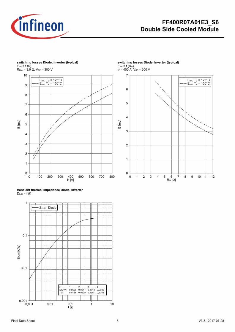
switchinglossesDiode,Inverter(typical)Erec=f(IF)RGon=3.6Ω,VCE=300V
IF [A]
E [m
J]
0 100 200 300 400 500 600 700 8000
1
2
3
4
5
6
7
8
9
10Erec, Tvj = 125°CErec, Tvj = 150°C
switchinglossesDiode,Inverter(typical)Erec=f(RG)IF=400A,VCE=300V
RG [Ω]
E [m
J]
0 1 2 3 4 5 6 7 8 9 10 11 120
1
2
3
4
5
6
7Erec, Tvj = 125°CErec, Tvj = 150°C
transientthermalimpedanceDiode,InverterZthJH=f(t)
t [s]
Zth
JH [K
/W]
0,001 0,01 0,1 1 100,001
0,01
0,1
1ZthJH : Diode
i:ri[K/W]:τi[s]:
10,05250,0186
20,02170,0525
30,17140,135
40,09830,5303
9
FF400R07A01E3_S6DoubleSideCooledModule
V3.3,2017-07-28Final Data Sheet
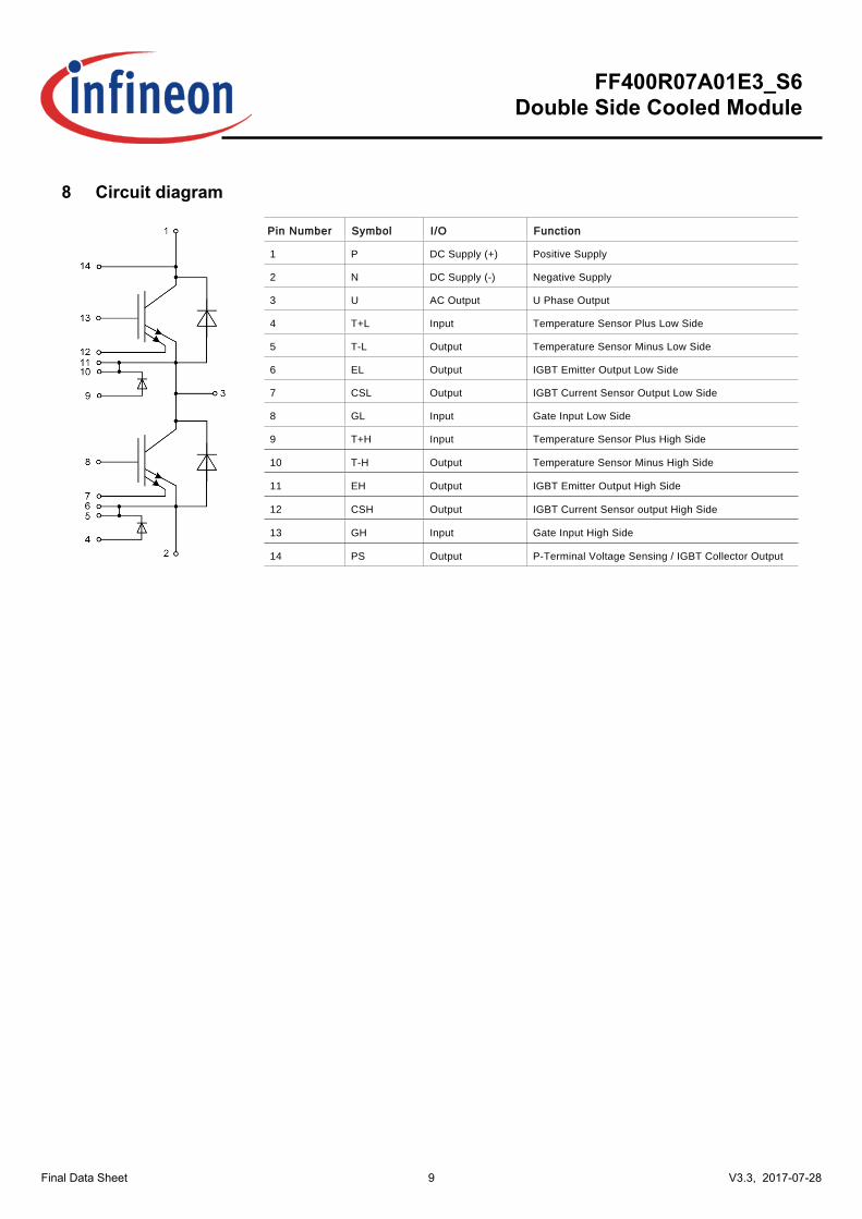
8Circuitdiagram
Pin Number Symbol I/O Function
1 P DC Supply (+) Positive Supply
2 N DC Supply (-) Negative Supply
3 U AC Output U Phase Output
4 T+L Input Temperature Sensor Plus Low Side
5 T-L Output Temperature Sensor Minus Low Side
6 EL Output IGBT Emitter Output Low Side
7 CSL Output IGBT Current Sensor Output Low Side
8 GL Input Gate Input Low Side
9 T+H Input Temperature Sensor Plus High Side
10 T-H Output Temperature Sensor Minus High Side
11 EH Output IGBT Emitter Output High Side
12 CSH Output IGBT Current Sensor output High Side
13 GH Input Gate Input High Side
14 PS Output P-Terminal Voltage Sensing / IGBT Collector Output
10
FF400R07A01E3_S6DoubleSideCooledModule
V3.3,2017-07-28Final Data Sheet
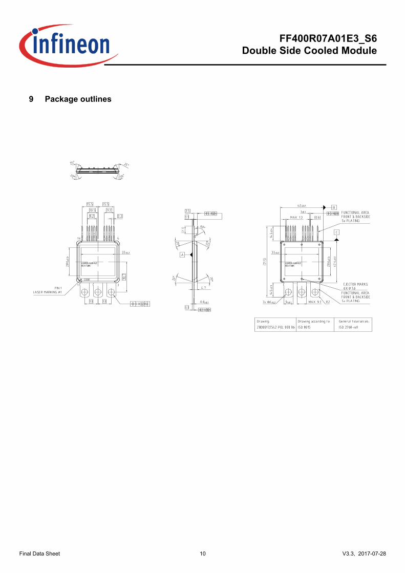
9Packageoutlines
11
FF400R07A01E3_S6DoubleSideCooledModule
V3.3,2017-07-28Final Data Sheet
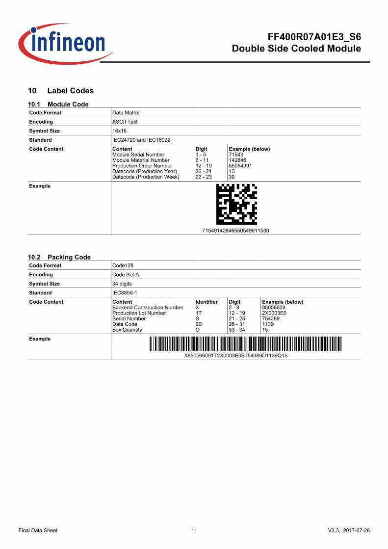
10LabelCodes10.1ModuleCodeCodeFormat Data Matrix
Encoding ASCII Text
SymbolSize 16x16
Standard IEC24720 and IEC16022
CodeContent ContentModule Serial NumberModule Material NumberProduction Order NumberDatecode (Production Year)Datecode (Production Week)
Digit1 - 56 - 1112 - 1920 - 2122 - 23
Example(below)71549142846550549911530
Example
71549142846550549911530
10.2PackingCodeCodeFormat Code128
Encoding Code Set A
SymbolSize 34 digits
Standard IEC8859-1
CodeContent ContentBackend Construction NumberProduction Lot NumberSerial NumberDate CodeBox Quantity
IdentifierX1TS9DQ
Digit2 - 912 - 1921 - 2528 - 3133 - 34
Example(below)950566092X0003E0754389113915
Example
X950566091T2X0003E0S754389D1139Q15
12
FF400R07A01E3_S6DoubleSideCooledModule
V3.3,2017-07-28Final Data Sheet
RevisionHistoryMajor changes since previous revision
Revision History
Reference Date DescriptionV1.0 2015-03-26 Initial Version
V1.1 2015-04-07 Extension of target data
V2.0 2016-02-02 Update of target data
V3.0 2016-11-07 Final Datasheet
V3.1 2016-11-08 Change of product name in description
V3.2 2016-12-13 Changes in description
V3.3 2017-07-28 Update mechanical drawing
13
FF400R07A01E3_S6DoubleSideCooledModule
V3.3,2017-07-28Final Data Sheet
Terms&ConditionsofusageEdition2014-05-30
PublishedbyInfineonTechnologiesAG81726Munich,Germany©2014InfineonTechnologiesAGAllRightsReserved.
LegalDisclaimerTheinformationgiveninthisdocumentshallinnoeventberegardedasaguaranteeofconditionsorcharacteristics.Withrespecttoanyexamplesorhintsgivenherein,anytypicalvaluesstatedhereinand/oranyinformationregardingtheapplicationofthedevice,InfineonTechnologiesherebydisclaimsanyandallwarrantiesandliabilitiesofanykind,includingwithoutlimitation,warrantiesofnon-infringementofintellectualpropertyrightsofanythirdparty.
InformationForfurtherinformationontechnology,deliverytermsandconditionsandprices,pleasecontactthenearestInfineonTechnologiesOffice(http://www.infineon.com)
WarningsDuetotechnicalrequirements,componentsmaycontaindangeroussubstances.Forinformationonthetypesinquestion,pleasecontactthenearestInfineonTechnologiesOffice.InfineonTechnologiescomponentsmaybeusedinlife-supportdevicesorsystemsonlywiththeexpresswrittenapprovalofInfineonTechnologies,ifafailureofsuchcomponentscanreasonablybeexpectedtocausethefailureofthatlife-supportdeviceorsystemortoaffectthesafetyoreffectivenessofthatdeviceorsystem.Lifesupportdevicesorsystemsareintendedtobeimplantedinthehumanbodyortosupportand/ormaintainandsustainand/orprotecthumanlife.Iftheyfail,itisreasonabletoassumethatthehealthoftheuserorotherpersonsmaybeendangered.
TrademarksTrademarksofInfineonTechnologiesAG
AURIX™,C166™,CanPAK™,CIPOS™,CIPURSE™,EconoPACK™,CoolMOS™,CoolSET™,CORECONTROL™,CROSSAVE™,DAVE™,DI-POL™,EasyPIM™,EconoBRIDGE™,EconoDUAL™,EconoPIM™,EconoPACK™,EiceDRIVER™,eupec™,FCOS™,HITFET™,HybridPACK™,I²RF™,ISOFACE™,IsoPACK™,MIPAQ™,ModSTACK™,my-d™,NovalithIC™,OptiMOS™,ORIGA™,POWERCODE™,PRIMARION™,PrimePACK™,PrimeSTACK™,PRO-SIL™,PROFET™,RASIC™,ReverSave™,SatRIC™,SIEGET™,SINDRION™,SIPMOS™,SmartLEWIS™,SOLIDFLASH™,TEMPFET™,thinQ™,TRENCHSTOP™,TriCore™.
OtherTrademarks
AdvanceDesignSystem™(ADS)ofAgilentTechnologies,AMBA™,ARM™,MULTI-ICE™,KEIL™,PRIMECELL™,REALVIEW™,THUMB™,µVision™ofARMLimited,UK.AUTOSAR™islicensedbyAUTOSARdevelopmentpartnership.Bluetooth™ofBluetoothSIGInc.CAT-iq™ofDECTForum.COLOSSUS™,FirstGPS™ofTrimbleNavigationLtd.EMV™ofEMVCo,LLC(VisaHoldingsInc.).EPCOS™ofEpcosAG.FLEXGO™ofMicrosoftCorporation.FlexRay™islicensedbyFlexRayConsortium.HYPERTERMINAL™ofHilgraeveIncorporated.IEC™ofCommissionElectrotechniqueInternationale.IrDA™ofInfraredDataAssociationCorporation.ISO™ofINTERNATIONALORGANIZATIONFORSTANDARDIZATION.MATLAB™ofMathWorks,Inc.MAXIM™ofMaximIntegratedProducts,Inc.MICROTEC™,NUCLEUS™ofMentorGraphicsCorporation.MIPI™ofMIPIAlliance,Inc.MIPS™ofMIPSTechnologies,Inc.,USA.muRata™ofMURATAMANUFACTURINGCO.,MICROWAVEOFFICE™(MWO)ofAppliedWaveResearchInc.,OmniVision™ofOmniVisionTechnologies,Inc.Openwave™OpenwaveSystemsInc.REDHAT™RedHat,Inc.RFMD™RFMicroDevices,Inc.SIRIUS™ofSiriusSatelliteRadioInc.SOLARIS™ofSunMicrosystems,Inc.SPANSION™ofSpansionLLCLtd.Symbian™ofSymbianSoftwareLimited.TAIYOYUDEN™ofTaiyoYudenCo.TEAKLITE™ofCEVA,Inc.TEKTRONIX™ofTektronixInc.TOKO™ofTOKOKABUSHIKIKAISHATA.UNIX™ofX/OpenCompanyLimited.VERILOG™,PALLADIUM™ofCadenceDesignSystems,Inc.VLYNQ™ofTexasInstrumentsIncorporated.VXWORKS™,WINDRIVER™ofWINDRIVERSYSTEMS,INC.ZETEX™ofDiodesZetexLimited.
Last update 2011-11-11

www.infineon.com
PublishedbyInfineonTechnologiesAG