Embed Size (px)
Citation preview
32 ECTI TRANSACTIONS ON ELECTRICAL ENG., ELECTRONICS, AND COMMUNICATIONS VOL.11, NO.1 February 2013
Doubly-Fed Induction Generator Wind TurbineModel for Fault Ride-Through Investigation
Yutana Chongjarearn1 , Non-member
ABSTRACT
The paper presents an investigation into the be-havior of a grid-connected, wind turbine drivenDoubly-Fed Induction Generator (DFIG) during Gridfaults which are represented by a voltage dip on allthree phases of the voltage supply. Stator-voltage-oriented vector control is used to decouple the ac-tive and reactive power generated by the machine.The dynamic DFIG model is used to simulate thebehaviour of the wind turbine generator during bothnormal and fault conditions. Simulation and exper-iment results are shown in a very good agreement.Further the model can be used to investigate Faultride-through performance of the DFIG.
Keywords: DFIGt, Fault ride-through, Doubly-FedInduction Generator
1. INTRODUCTION
The Doubly-Fed Induction Generator is widelyused for large grid-connected, variable-speed windturbines. Variable speed wind turbines offer a num-ber of advantages [1] when compared with fixed-speedturbines, including operation over a wide range ofwind velocities, independent control of active and re-active power, reduced flicker and lower acoustic noiselevels.
As the amount of installed wind power increases,it is becoming increasingly more important that tur-bine generators remain connected and support thegrid transmission network during transient systemdisturbances- so-called fault ride-through (FRT), asspecified by various national grid codes [2].
To study the fault ride-through capability of theDFIG, an accurate model of the system is needed;this must include details of mechanical, electrical andcontrol systems’ behavior if it is to accurately predictthe fault ride through performance of the generator.
In this paper, a new model for a vector controlleddoubly-fed induction generator is developed to inves-tigate drive fault through characteristics, allowing forthe switching effects of all IGBTs and anti-paralleldiodes. The model is used to study the fault ride
Manuscript received on July 15, 2012 ; revised on October12, 2012.1 The author is with Department of Electrical Engineering,
Faculty of Engineering Dhurakij Pundit University, Bangkok,Thailand., E-mail: [email protected]
through performance of the DFIG in accordance withthe transmission system grid codes.
The paper is organized as follows. First, the sys-tem modelling is reviewed and discussed. Then, sim-ulation results of two fault scenarios is obtained andcompared with measurements. Finally, the modelwill be used to investigate the FRT capability of theDFIG.
2. DYNAMIC MODEL OF A DOUBLY FEDINDUCTION GENERATOR
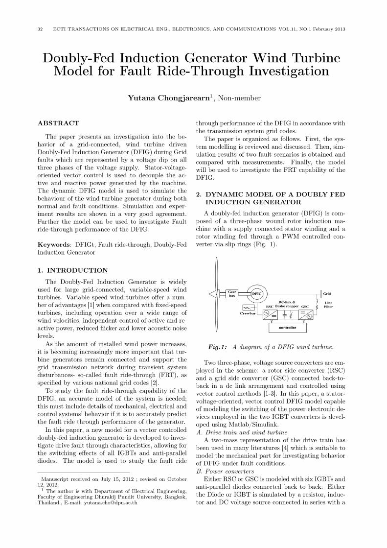
A doubly-fed induction generator (DFIG) is com-posed of a three-phase wound rotor induction ma-chine with a supply connected stator winding and arotor winding fed through a PWM controlled con-verter via slip rings (Fig. 1).
Fig.1: A diagram of a DFIG wind turbine.
Two three-phase, voltage source converters are em-ployed in the scheme: a rotor side converter (RSC)and a grid side converter (GSC) connected back-to-back in a dc link arrangement and controlled usingvector control methods [1-3]. In this paper, a stator-voltage-oriented, vector control DFIG model capableof modeling the switching of the power electronic de-vices employed in the two IGBT converters is devel-oped using Matlab/Simulink.A. Drive train and wind turbine
A two-mass representation of the drive train hasbeen used in many literatures [4] which is suitable tomodel the mechanical part for investigating behaviorof DFIG under fault conditions.B. Power converters
Either RSC or GSC is modeled with six IGBTs andanti-parallel diodes connected back to back. Eitherthe Diode or IGBT is simulated by a resistor, induc-tor and DC voltage source connected in series with a
Doubly-Fed Induction Generator Wind Turbine Model for Fault Ride-Through Investigation 33
switch. The Diode switching operation is controlledby the anode-cathode voltage and current while IG-BTs switching operation is controlled by the gate sig-nal, the collector-emitter voltage and current whicheach model can be found in MATLAB/Simulink (sim-power toolblox). Switching of these IGBTs is oper-ated with the Pulse-Width Modulation Techniques(PWM) as shown in vector control scheme. In thiscontrol scheme, the task of RSC is to decouple controlof the stator active and reactive power of the DFIGwhile the GSC has to keep the DC-link voltage con-stant at a reference demand regardless of the magni-tude and direction of the rotor power. Both convert-ers are normally set to operate at unity power factorusing stator voltage-oriented vector control. The con-verters are controlled independently with a switchingfrequency of 5 kHz, according to a laboratory test.C. DFIG
The dynamic model of DFIG is the space vectorrepresentation of electrical quantities with the stateequation (1)-(2) for stator and rotor side voltage [3] .
vs = Rsis +1
ωb
dλs
dt+ ωeMλs (1)
vr = Rr ir +1
ωb
dλr
dt+ (ωe − ωr)Mλr (2)
Where M represents a space rotator namelyM =[0 -1;1 0].Stator and rotor flux linkage can be given by equa-
tion (3)-(4).
λs = Lmir + Lsis (3)
λr = Lmis + Lr ir (4)
D. DFIG Power and Current ControlFrom the equation (1)-(2), all quantities are de-
composed into the d-q frame using stator voltage-oriented techniques. All voltages and currents in d-qframe can be substituted in a power flow equation asmentioned in [3]. Therefore, the stator active (Ps)and reactive (Qs) power generated by the DFIG canbe expressed in equation (5)-(6).
Ps = vsdisd = vsd
(−Lmird
Ls
)(5)
where isd = −Lmird/Ls
Qs = −vsdisq = −vsd
(λsq
Ls− Lmirq
Ls
)(6)
where isq = (λsq − Lmirq)/Ls
Since the q-axis flux linkage component (λsq), thestator self inductance (Ls), the mutual inductance(Lm) and the d-axis stator voltage component (Vsd)are constant, the DFIG active power and reactivepower are independently controlled by the d-axis ro-tor current component (ird) and the q-axis rotor cur-rent component (irq), respectively.
In RSC power controller, a typical power-speedcurve is used to define the reference output power forthe controller according to the Turbine Characteristicin which to track the maximum power at each windand generator speed. The reference rotor currents forcontrol of active and reactive powers can be expressedas
irdref =PI(Pref−Pmeas), irqref =PI(Qref−Qmeas) (7)
Where irdref and irqref are references for RSC powercontrol and PI is the proportional and integral gain.
From the equation (2), the rotor side voltages canbe rewritten in the d-q-axis components.
vrd=Rrird−(ωe−ωr)σLrirq−(ωe−ωr)Lm
Lsλsq+
1
ωbσLr
dtrddt
vrq=Rrirq+(ωe−ωr)σLrird+1
ωb
(σLr
dirqdt
+Lm
Ls
dλsq
dt
)(8)
Where σ = 1− L2m/LrLs.
There are rotational emf term and transformer emfterm (the derivative of flux) in each component. Sincethe operating slip range of DFIG is limited, the effectsof the former term are very small and also the statorflux is assumed constant. Therefore, the referencerotor voltages for control of active and reactive powerscan be expressed as
vrdref = PI(irdref − ird)
vrqref = PI(irqref − irq) (9)
Where vrdref , vrqref are references for RSC currentcontrol and PI is the proportional and integral gain.
In GSC controller, similar to RSC, all quanti-ties are decomposed into the d-q frame using statorvoltage-oriented techniques. All voltages and cur-rents between grid and GSC converter can be ex-pressed in d-q frame as
vcd = Ricd + Ldicddt
− ωeLicq + vcd1
vcq = Ricq + Ldicqdt
− ωeLicd + vcq1 (10)
Where R, L is a line side filter between Grid and GSC.The active (Pc) and reactive (Qc) power as men-
tioned in [3] can be expressed in equation (11)-(12).
34 ECTI TRANSACTIONS ON ELECTRICAL ENG., ELECTRONICS, AND COMMUNICATIONS VOL.11, NO.1 February 2013
Pc = vcdicd (11)
Qc = −vcdicq (12)
As shown in equations, the active and reactivepower is proportional to the d-axis and q-axis con-verter current component (icdq).
In DC-Link voltage control, the energy stored inthe DC-link capacitor is considered as cv2dc/2. Thetime derivative of the energy is equal to the sum ofGSC and RSC power. Hence the DC-Link equationsare obtained as:
1
2cdv2dcdt
= PGSC − PRSC (13)
Where PGSC = vcdicd, PRSC = vrdird + vrqirqand icrsc = Pr/vdc, icgsc = Pc/vdc. Hence,
1
2cdvdcdt
= icgsc − icrsc (14)
From equation (13) and (14), it can be concludedthat the DC-link voltage can be controlled using theGSC current in the d-axis component while the reac-tive power is controlled using the GSC current in theq-axis component.
From equation (10), it can be rearranged as
vcd1 = −(Ricd + L
dicddt
)+ ωeLicq + vcd
vcq1 = −(Ricd + L
dicqdt
)− ωeLicd (15)
Therefore, the reference voltages for GSC can beexpressed as:
vcdref = −PI(icdref − icd) + feedforward_term
vcqref = −PI(icqref − icq) + feedforward_term
(16)
Where PI is the proportional and integral gain andvcdref , vcqref are references for GSC current control.
In order to offer preferable dynamic response togrid voltage dips, the feed-forward term is estimatedto the stator voltage [5].
To generate 3-phase PWM signals to drive the con-verters connected to the rotor and grid sides, the volt-age demand needs to be scaled by using the factor, K1and DC-link voltage, vdc to produce the modulationfactor, mr for RSC and mc for GSC. The modulationfactor can be given by
mr = K1 ∗ vrdqref/vdc (17)mc = K1 ∗ vcdqref/vdc (18)
Where K1 = ((2√2) ∗ vrac/
√3).
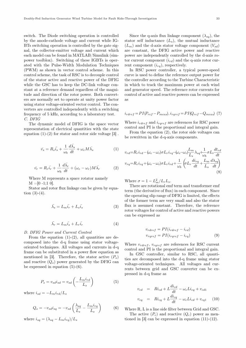
A diagram of vector control scheme for RSC andGSC is shown in Fig. 2.
3. MODEL VALIDATION
The model is validated using the laboratory DFIGtest rig operating at speed of 1.12 p.u. (12% abovesynchronous) and generating 5kW (0.67 pu) power atunity power factor.
Fig.2: Vector control scheme for RSC and GSC.
Two fault scenarios regarding the FRT GB gridcode are investigated in the paper as concluded inTable 1.
Table 1: Two cases of the fault scenarios.
The applied fault is a 3-phase grid voltage dip froma normal voltage (1 pu) to a fault voltage of 0 and0.15 pu, respectively. All fault scenarios initiate attime of 1 sec and clear at time of 1.14 and 1.5 sec,respectively. After that case of 0.15 pu fault volt-age will be investigated for the FRT capability of theDFIG.
4. RESULTS AND DISCUSSION
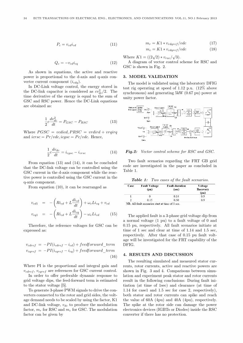
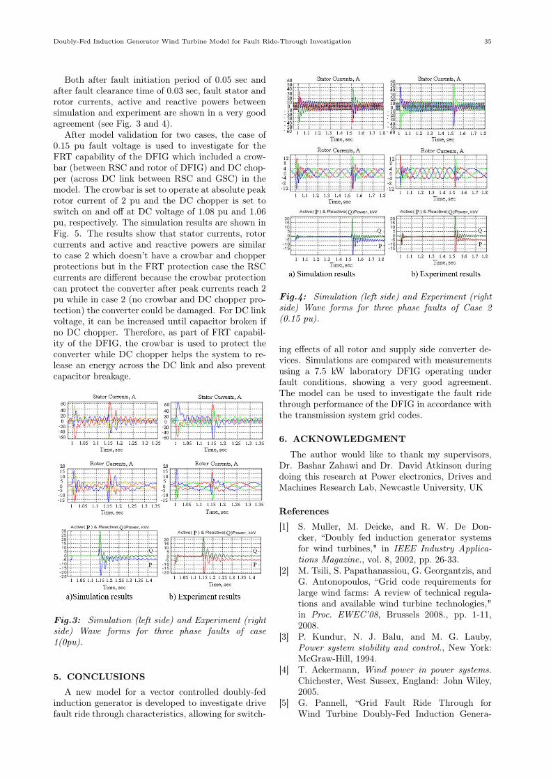
The resulting simulated and measured stator cur-rents, rotor currents, active and reactive powers areshown in Fig. 3 and 4. Comparisons between simu-lation and experiment peak stator and rotor currentsresult in the following conclusions: During fault ini-tiation (at time of 1sec) and clearance (at time of1.14 for case1 and 1.5 sec for case 2, respectively),both stator and rotor currents can spike and reachthe value of 60A (4pu) and 40A (4pu), respectively.The spike at the rotor side can damage the powerelectronics devices (IGBTs or Diodes) inside the RSCconverter if there has no protection.
Doubly-Fed Induction Generator Wind Turbine Model for Fault Ride-Through Investigation 35
Both after fault initiation period of 0.05 sec andafter fault clearance time of 0.03 sec, fault stator androtor currents, active and reactive powers betweensimulation and experiment are shown in a very goodagreement (see Fig. 3 and 4).
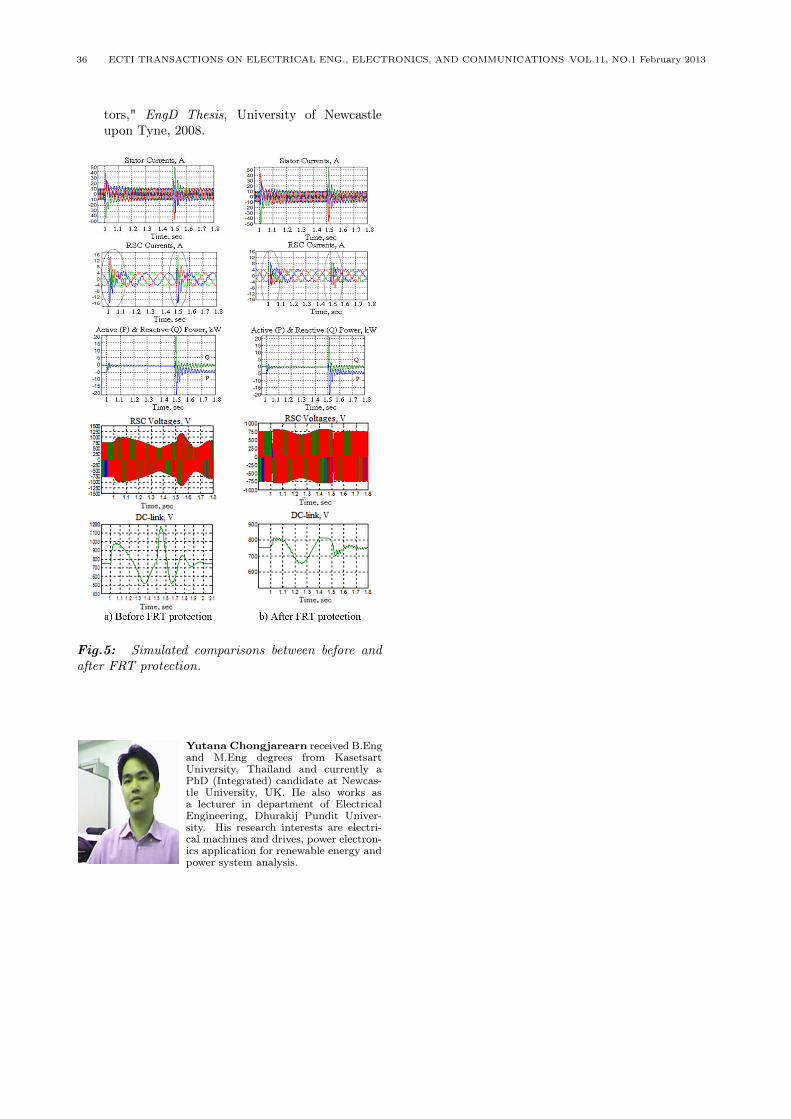
After model validation for two cases, the case of0.15 pu fault voltage is used to investigate for theFRT capability of the DFIG which included a crow-bar (between RSC and rotor of DFIG) and DC chop-per (across DC link between RSC and GSC) in themodel. The crowbar is set to operate at absolute peakrotor current of 2 pu and the DC chopper is set toswitch on and off at DC voltage of 1.08 pu and 1.06pu, respectively. The simulation results are shown inFig. 5. The results show that stator currents, rotorcurrents and active and reactive powers are similarto case 2 which doesn’t have a crowbar and chopperprotections but in the FRT protection case the RSCcurrents are different because the crowbar protectioncan protect the converter after peak currents reach 2pu while in case 2 (no crowbar and DC chopper pro-tection) the converter could be damaged. For DC linkvoltage, it can be increased until capacitor broken ifno DC chopper. Therefore, as part of FRT capabil-ity of the DFIG, the crowbar is used to protect theconverter while DC chopper helps the system to re-lease an energy across the DC link and also preventcapacitor breakage.
Fig.3: Simulation (left side) and Experiment (rightside) Wave forms for three phase faults of case1(0pu).
5. CONCLUSIONS
A new model for a vector controlled doubly-fedinduction generator is developed to investigate drivefault ride through characteristics, allowing for switch-
Fig.4: Simulation (left side) and Experiment (rightside) Wave forms for three phase faults of Case 2(0.15 pu).
ing effects of all rotor and supply side converter de-vices. Simulations are compared with measurementsusing a 7.5 kW laboratory DFIG operating underfault conditions, showing a very good agreement.The model can be used to investigate the fault ridethrough performance of the DFIG in accordance withthe transmission system grid codes.
6. ACKNOWLEDGMENT
The author would like to thank my supervisors,Dr. Bashar Zahawi and Dr. David Atkinson duringdoing this research at Power electronics, Drives andMachines Research Lab, Newcastle University, UK
References
[1] S. Muller, M. Deicke, and R. W. De Don-cker, “Doubly fed induction generator systemsfor wind turbines," in IEEE Industry Applica-tions Magazine., vol. 8, 2002, pp. 26-33.
[2] M. Tsili, S. Papathanassiou, G. Georgantzis, andG. Antonopoulos, “Grid code requirements forlarge wind farms: A review of technical regula-tions and available wind turbine technologies,"in Proc. EWEC’08, Brussels 2008., pp. 1-11,2008.
[3] P. Kundur, N. J. Balu, and M. G. Lauby,Power system stability and control., New York:McGraw-Hill, 1994.
[4] T. Ackermann, Wind power in power systems.Chichester, West Sussex, England: John Wiley,2005.
[5] G. Pannell, “Grid Fault Ride Through forWind Turbine Doubly-Fed Induction Genera-
36 ECTI TRANSACTIONS ON ELECTRICAL ENG., ELECTRONICS, AND COMMUNICATIONS VOL.11, NO.1 February 2013
tors," EngD Thesis, University of Newcastleupon Tyne, 2008.
Fig.5: Simulated comparisons between before andafter FRT protection.
Yutana Chongjarearn received B.Engand M.Eng degrees from KasetsartUniversity, Thailand and currently aPhD (Integrated) candidate at Newcas-tle University, UK. He also works asa lecturer in department of ElectricalEngineering, Dhurakij Pundit Univer-sity. His research interests are electri-cal machines and drives, power electron-ics application for renewable energy andpower system analysis.