Embed Size (px)
Citation preview

Massachusetts School Building Authority Project Nº: 200800770010 / 200800770100G 15 August 2011 50% Construction Document Submission – Douglas Elementary School / Middle School
D O U G L A S E L E M E N T A R Y S C H O O L
D O U G L A S M I D D L E S C H O O L M A S S A C H U S E T T S S C H O O L B U I L D I N G A U T H O R I T Y
5 0 % C O N S T R U C T I O N D O C U M E N T S U B M I S S I O N
P A R T F O U R : B U I L D I N G D E S I G N
• H E A T G A I N & L O S S C A L C U L A T I O N S

Air System Sizing Summary for Zone 1Project Name: 20100331.01 HVAC Loads 07/15/2011Prepared by: RDK Engineers 09:20AM
Air System Information Air System Name Zone 1 Equipment Class UNDEF Air System Type SZCAV
Number of zones 1Floor Area 16800.0 ft²Location Springfield, Massachusetts
Sizing Calculation InformationZone and Space Sizing Method:
Zone CFM Sum of space airflow rates Space CFM Individual peak space loads
Calculation Months Jan to DecSizing Data Calculated
Central Cooling Coil Sizing Data Total coil load 36.9 Tons Total coil load 442.7 MBH Sensible coil load 360.2 MBH Coil CFM at Jul 1500 18388 CFM Max block CFM 18388 CFM Sum of peak zone CFM 18388 CFM Sensible heat ratio 0.814 ft²/Ton 455.4 BTU/(hr-ft²) 26.3 Water flow @ 10.0 °F rise 88.58 gpm
Load occurs at Jul 1500OA DB / WB 90.0 / 72.0 °FEntering DB / WB 79.3 / 67.5 °FLeaving DB / WB 61.0 / 59.9 °FCoil ADP 59.0 °FBypass Factor 0.100Resulting RH 59 %Design supply temp. 58.0 °FZone T-stat Check 1 of 1 OKMax zone temperature deviation 0.0 °F
Central Heating Coil Sizing Data Max coil load 595.9 MBH Coil CFM at Des Htg 18388 CFM Max coil CFM 18388 CFM Water flow @ 20.0 °F drop 59.62 gpm
Load occurs at Des HtgBTU/(hr-ft²) 35.5Ent. DB / Lvg DB 51.8 / 82.1 °F
Supply Fan Sizing Data Actual max CFM 18388 CFM Standard CFM 18226 CFM Actual max CFM/ft² 1.09 CFM/ft²
Fan motor BHP 0.00 BHPFan motor kW 0.00 kWFan static 0.00 in wg
Outdoor Ventilation Air Data Design airflow CFM 4339 CFM CFM/ft² 0.26 CFM/ft²
CFM/person 21.70 CFM/person
Hourly Analysis Program v4.51 Page 1 of 4

Zone Sizing Summary for Zone 1Project Name: 20100331.01 HVAC Loads 07/15/2011Prepared by: RDK Engineers 09:20AM
Air System Information Air System Name Zone 1 Equipment Class UNDEF Air System Type SZCAV
Number of zones 1Floor Area 16800.0 ft²Location Springfield, Massachusetts
Sizing Calculation InformationZone and Space Sizing Method:
Zone CFM Sum of space airflow rates Space CFM Individual peak space loads
Calculation Months Jan to DecSizing Data Calculated
Zone Sizing Data
Maximum Design Minimum Time Maximum ZoneCooling Air Air of Heating Floor
Sensible Flow Flow Peak Load Area ZoneZone Name (MBH) (CFM) (CFM) Load (MBH) (ft²) CFM/ft²Zone 1 308.4 18388 18388 Aug 1400 250.3 16800.0 1.09
Zone Terminal Sizing DataNo Zone Terminal Sizing Data required for this system.
Space Loads and Airflows
Cooling Time Air Heating FloorZone Name / Sensible of Flow Load Area Space Space Name Mult. (MBH) Load (CFM) (MBH) (ft²) CFM/ft²Zone 1 3-Classroom 8 1 30.3 Jul 1300 1666 26.1 949.0 1.76 3-Classroom 7 1 29.6 Jul 1300 1627 21.7 949.0 1.71 3-Classroom 6 1 29.6 Jul 1300 1627 21.7 949.0 1.71 3-Classroom 5 1 30.7 Jul 1400 1686 25.7 944.0 1.79 2-Classroom 8 1 25.7 Jul 1400 1412 20.3 949.0 1.49 2-Classroom 7 1 25.2 Jul 1400 1385 17.4 949.0 1.46 2-Classroom 6 1 25.2 Jul 1400 1385 17.4 949.0 1.46 2-Classroom 5 1 26.3 Jul 1500 1448 20.6 949.0 1.53 3-Corridor 1 19.7 Jul 1300 1082 10.4 3026.0 0.36 2-Corridor 1 10.5 Jan 1900 577 0.0 3022.0 0.19 1-Corridor B 1 8.7 Jul 1500 648 17.3 1565.0 0.41 1-Corridor C 1 68.9 Oct 1300 3784 51.3 1375.0 2.75 3-Storage 2 1 0.4 Jul 1300 21 0.2 60.0 0.36 3-Staff Toilet 2 1 0.3 Jul 1300 16 0.2 45.0 0.36 2-Storage C 1 0.3 Jan 1900 14 0.0 75.0 0.19 2-Staff Toilet B 1 0.2 Jan 1900 9 0.0 45.0 0.19
Hourly Analysis Program v4.51 Page 2 of 4

Ventilation Sizing Summary for Zone 1Project Name: 20100331.01 HVAC Loads 07/15/2011Prepared by: RDK Engineers 09:20AM
1. Summary Ventilation Sizing Method ASHRAE Std 62.1-2007 Design Condition Heating operation Occupant Diversity 1.000 Uncorrected Ventilation Airflow Rate 3450 CFM System Ventilation Efficiency 0.795 Design Ventilation Airflow Rate 4339 CFM
2. Space Ventilation Analysis TableFloor Required Time Required Air Required Uncorrected Space
Supply Air Area Outdoor Air Averaged Outdoor Air Distribution Outdoor Air Outdoor Air VentilationZone Name / Space Name Mult. (CFM) (ft²) (CFM/ft²) Occupancy (CFM/person) Effectiveness (CFM) (CFM) EfficiencyZone 1 3-Classroom 8 1 1666 949.0 0.12 25.0 10.00 0.80 455 364 0.915 3-Classroom 7 1 1627 949.0 0.12 25.0 10.00 0.80 455 364 0.908 3-Classroom 6 1 1627 949.0 0.12 25.0 10.00 0.80 455 364 0.908 3-Classroom 5 1 1686 944.0 0.12 25.0 10.00 0.80 454 363 0.918 2-Classroom 8 1 1412 949.0 0.12 25.0 10.00 0.80 455 364 0.866 2-Classroom 7 1 1385 949.0 0.12 25.0 10.00 0.80 455 364 0.859 2-Classroom 6 1 1385 949.0 0.12 25.0 10.00 0.80 455 364 0.859 2-Classroom 5 1 1448 949.0 0.12 25.0 10.00 0.80 455 364 0.873 3-Corridor 1 1082 3026.0 0.06 0.0 0.00 0.80 227 182 0.978 2-Corridor 1 577 3022.0 0.06 0.0 0.00 0.80 227 181 0.795 1-Corridor B 1 648 1565.0 0.06 0.0 0.00 0.80 117 94 1.006 1-Corridor C 1 3784 1375.0 0.06 0.0 0.00 0.80 103 83 1.160 3-Storage 2 1 21 60.0 0.00 0.0 0.00 0.80 0 0 1.188 3-Staff Toilet 2 1 16 45.0 0.00 0.0 0.00 0.80 0 0 1.188 2-Storage C 1 14 75.0 0.00 0.0 0.00 0.80 0 0 1.188 2-Staff Toilet B 1 9 45.0 0.00 0.0 0.00 0.80 0 0 1.188
Totals (incl. Space Multipliers) 18388 3450 0.795
Hourly Analysis Program v4.51 Page 3 of 4
Air System Design Load Summary for Zone 1Project Name: 20100331.01 HVAC Loads 07/15/2011Prepared by: RDK Engineers 09:20AM
DESIGN COOLING DESIGN HEATINGCOOLING DATA AT Jul 1500 HEATING DATA AT DES HTGCOOLING OA DB / WB 90.0 °F / 72.0 °F HEATING OA DB / WB -5.0 °F / -6.2 °F
Sensible Latent Sensible LatentZONE LOADS Details (BTU/hr) (BTU/hr) Details (BTU/hr) (BTU/hr)Window & Skylight Solar Loads 1683 ft² 80736 - 1683 ft² - -Wall Transmission 4736 ft² 8980 - 4736 ft² 26589 -Roof Transmission 6922 ft² 17090 - 6922 ft² 20593 -Window Transmission 1683 ft² 12686 - 1683 ft² 82046 -Skylight Transmission 0 ft² 0 - 0 ft² 0 -Door Loads 0 ft² 0 - 0 ft² 0 -Floor Transmission 2940 ft² 0 - 2940 ft² 0 -Partitions 0 ft² 0 - 0 ft² 0 -Ceiling 0 ft² 0 - 0 ft² 0 -Overhead Lighting 16800 W 48742 - 0 0 -Task Lighting 7587 W 23734 - 0 0 -Electric Equipment 3600 W 11463 - 0 0 -People 200 40651 40000 0 0 0Infiltration - 17690 7174 - 88450 0Miscellaneous - 0 0 - 0 0Safety Factor 15% / 15% 39266 7076 15% 32652 0>> Total Zone Loads - 301038 54250 - 250330 0Zone Conditioning - 295156 54250 - 250400 0Plenum Wall Load 0% 0 - 0 0 -Plenum Roof Load 0% 0 - 0 0 -Plenum Lighting Load 0% 0 - 0 0 -Return Fan Load 18388 CFM 0 - 18388 CFM 0 -Ventilation Load 4339 CFM 65002 28254 4339 CFM 345468 0Supply Fan Load 18388 CFM 0 - 18388 CFM 0 -Space Fan Coil Fans - 0 - - 0 -Duct Heat Gain / Loss 0% 0 - 0% 0 ->> Total System Loads - 360158 82504 - 595867 0Central Cooling Coil - 360158 82512 - 0 0Central Heating Coil - 0 - - 595868 ->> Total Conditioning - 360158 82512 - 595868 0Key: Positive values are clg loads Positive values are htg loads
Negative values are htg loads Negative values are clg loads
Hourly Analysis Program v4.51 Page 4 of 4

Air System Sizing Summary for Zone 2Project Name: 20100331.01 HVAC Loads 07/15/2011Prepared by: RDK Engineers 09:21AM
Air System Information Air System Name Zone 2 Equipment Class UNDEF Air System Type SZCAV
Number of zones 1Floor Area 3162.0 ft²Location Springfield, Massachusetts
Sizing Calculation InformationZone and Space Sizing Method:
Zone CFM Sum of space airflow rates Space CFM Individual peak space loads
Calculation Months Jan to DecSizing Data Calculated
Central Cooling Coil Sizing Data Total coil load 5.8 Tons Total coil load 69.3 MBH Sensible coil load 57.3 MBH Coil CFM at Jul 1500 2952 CFM Max block CFM 2952 CFM Sum of peak zone CFM 2952 CFM Sensible heat ratio 0.827 ft²/Ton 547.8 BTU/(hr-ft²) 21.9 Water flow @ 10.0 °F rise 13.86 gpm
Load occurs at Jul 1500OA DB / WB 90.0 / 72.0 °FEntering DB / WB 78.2 / 66.5 °FLeaving DB / WB 60.1 / 59.0 °FCoil ADP 58.1 °FBypass Factor 0.100Resulting RH 57 %Design supply temp. 58.0 °FZone T-stat Check 1 of 1 OKMax zone temperature deviation 0.0 °F
Central Heating Coil Sizing Data Max coil load 80.0 MBH Coil CFM at Des Htg 2952 CFM Max coil CFM 2952 CFM Water flow @ 20.0 °F drop 8.00 gpm
Load occurs at Des HtgBTU/(hr-ft²) 25.3Ent. DB / Lvg DB 58.2 / 83.5 °F
Supply Fan Sizing Data Actual max CFM 2952 CFM Standard CFM 2926 CFM Actual max CFM/ft² 0.93 CFM/ft²
Fan motor BHP 0.00 BHPFan motor kW 0.00 kWFan static 0.00 in wg
Outdoor Ventilation Air Data Design airflow CFM 436 CFM CFM/ft² 0.14 CFM/ft²
CFM/person 15.57 CFM/person
Hourly Analysis Program v4.51 Page 1 of 4

Zone Sizing Summary for Zone 2Project Name: 20100331.01 HVAC Loads 07/15/2011Prepared by: RDK Engineers 09:21AM
Air System Information Air System Name Zone 2 Equipment Class UNDEF Air System Type SZCAV
Number of zones 1Floor Area 3162.0 ft²Location Springfield, Massachusetts
Sizing Calculation InformationZone and Space Sizing Method:
Zone CFM Sum of space airflow rates Space CFM Individual peak space loads
Calculation Months Jan to DecSizing Data Calculated
Zone Sizing Data
Maximum Design Minimum Time Maximum ZoneCooling Air Air of Heating Floor
Sensible Flow Flow Peak Load Area ZoneZone Name (MBH) (CFM) (CFM) Load (MBH) (ft²) CFM/ft²Zone 1 52.5 2952 2952 Jul 1500 46.4 3162.0 0.93
Zone Terminal Sizing DataNo Zone Terminal Sizing Data required for this system.
Space Loads and Airflows
Cooling Time Air Heating FloorZone Name / Sensible of Flow Load Area Space Space Name Mult. (MBH) Load (CFM) (MBH) (ft²) CFM/ft²Zone 1 1-Staff Lunch 1 7.4 Jul 1700 406 7.2 312.0 1.30 1-Title 1 Office 1 6.1 Jul 1500 333 7.8 248.0 1.34 1-Office A 1 4.0 Jul 1400 222 3.9 155.0 1.43 1-Principal 1 6.5 Jul 1000 357 6.5 240.0 1.49 1-Office B 1 3.7 Jul 1400 205 3.5 130.0 1.58 1-Office C 1 3.8 Jul 1400 207 3.5 133.0 1.56 1-Exam/Nurse 1 11.3 Aug 1500 624 13.1 616.0 1.01 1-Nurses Toilet 1 0.6 Sep 1600 34 0.8 64.0 0.53 1-Storage A 1 0.1 Jan 1900 8 0.0 40.0 0.19 1-Waiting 1 0.4 Jan 1900 21 0.0 109.0 0.19 1-General Office 1 3.5 Jan 1900 191 0.0 260.0 0.73 1-Workroom 1 1.6 Jan 1900 87 0.0 110.0 0.79 1-Storage B 1 0.2 Jan 1900 9 0.0 45.0 0.19 1-Corridor A 1 1.4 Jan 1900 77 0.0 401.0 0.19 1-Conf 1 2.9 Jan 1900 160 0.0 239.0 0.67 1-Staff Toilet 1 0.2 Jan 1900 11 0.0 60.0 0.19
Hourly Analysis Program v4.51 Page 2 of 4

Ventilation Sizing Summary for Zone 2Project Name: 20100331.01 HVAC Loads 07/15/2011Prepared by: RDK Engineers 09:21AM
1. Summary Ventilation Sizing Method ASHRAE Std 62.1-2007 Design Condition Heating operation Occupant Diversity 1.000 Uncorrected Ventilation Airflow Rate 311 CFM System Ventilation Efficiency 0.713 Design Ventilation Airflow Rate 436 CFM
2. Space Ventilation Analysis TableFloor Required Time Required Air Required Uncorrected Space
Supply Air Area Outdoor Air Averaged Outdoor Air Distribution Outdoor Air Outdoor Air VentilationZone Name / Space Name Mult. (CFM) (ft²) (CFM/ft²) Occupancy (CFM/person) Effectiveness (CFM) (CFM) EfficiencyZone 1 1-Staff Lunch 1 406 312.0 0.06 12.0 5.00 0.80 98 79 0.863 1-Title 1 Office 1 333 248.0 0.06 1.0 5.00 0.80 25 20 1.031 1-Office A 1 222 155.0 0.06 1.0 5.00 0.80 18 14 1.025 1-Principal 1 357 240.0 0.06 1.0 5.00 0.80 24 19 1.037 1-Office B 1 205 130.0 0.06 1.0 5.00 0.80 16 13 1.027 1-Office C 1 207 133.0 0.06 1.0 5.00 0.80 16 13 1.027 1-Exam/Nurse 1 624 616.0 0.06 3.0 5.00 0.80 65 52 1.001 1-Nurses Toilet 1 34 64.0 0.00 0.0 0.00 0.80 0 0 1.105 1-Storage A 1 8 40.0 0.00 0.0 0.00 0.80 0 0 1.105 1-Waiting 1 21 109.0 0.00 0.0 0.00 0.80 0 0 1.105 1-General Office 1 191 260.0 0.06 2.0 5.00 0.80 32 26 0.937 1-Workroom 1 87 110.0 0.06 1.0 5.00 0.80 15 12 0.939 1-Storage B 1 9 45.0 0.00 0.0 0.00 0.80 0 0 1.105 1-Corridor A 1 77 401.0 0.06 0.0 0.00 0.80 30 24 0.713 1-Conf 1 160 239.0 0.06 5.0 5.00 0.80 49 39 0.798 1-Staff Toilet 1 11 60.0 0.00 0.0 0.00 0.80 0 0 1.105
Totals (incl. Space Multipliers) 2952 311 0.713
Hourly Analysis Program v4.51 Page 3 of 4
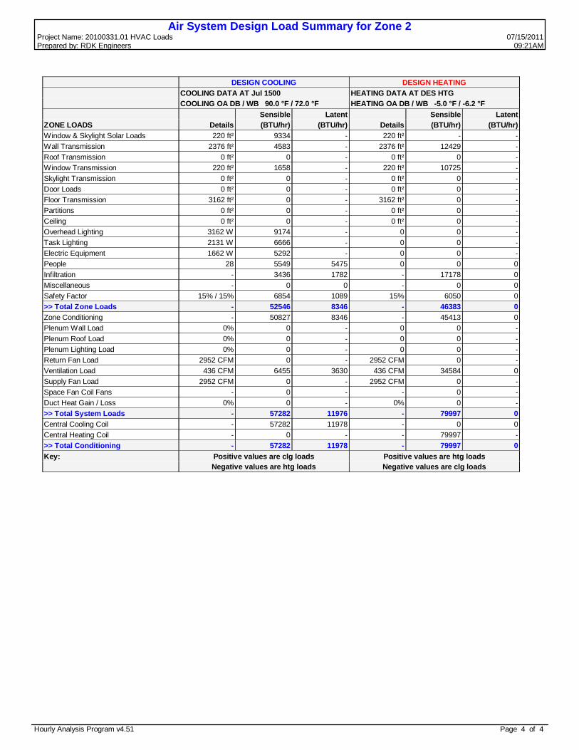
Air System Design Load Summary for Zone 2Project Name: 20100331.01 HVAC Loads 07/15/2011Prepared by: RDK Engineers 09:21AM
DESIGN COOLING DESIGN HEATINGCOOLING DATA AT Jul 1500 HEATING DATA AT DES HTGCOOLING OA DB / WB 90.0 °F / 72.0 °F HEATING OA DB / WB -5.0 °F / -6.2 °F
Sensible Latent Sensible LatentZONE LOADS Details (BTU/hr) (BTU/hr) Details (BTU/hr) (BTU/hr)Window & Skylight Solar Loads 220 ft² 9334 - 220 ft² - -Wall Transmission 2376 ft² 4583 - 2376 ft² 12429 -Roof Transmission 0 ft² 0 - 0 ft² 0 -Window Transmission 220 ft² 1658 - 220 ft² 10725 -Skylight Transmission 0 ft² 0 - 0 ft² 0 -Door Loads 0 ft² 0 - 0 ft² 0 -Floor Transmission 3162 ft² 0 - 3162 ft² 0 -Partitions 0 ft² 0 - 0 ft² 0 -Ceiling 0 ft² 0 - 0 ft² 0 -Overhead Lighting 3162 W 9174 - 0 0 -Task Lighting 2131 W 6666 - 0 0 -Electric Equipment 1662 W 5292 - 0 0 -People 28 5549 5475 0 0 0Infiltration - 3436 1782 - 17178 0Miscellaneous - 0 0 - 0 0Safety Factor 15% / 15% 6854 1089 15% 6050 0>> Total Zone Loads - 52546 8346 - 46383 0Zone Conditioning - 50827 8346 - 45413 0Plenum Wall Load 0% 0 - 0 0 -Plenum Roof Load 0% 0 - 0 0 -Plenum Lighting Load 0% 0 - 0 0 -Return Fan Load 2952 CFM 0 - 2952 CFM 0 -Ventilation Load 436 CFM 6455 3630 436 CFM 34584 0Supply Fan Load 2952 CFM 0 - 2952 CFM 0 -Space Fan Coil Fans - 0 - - 0 -Duct Heat Gain / Loss 0% 0 - 0% 0 ->> Total System Loads - 57282 11976 - 79997 0Central Cooling Coil - 57282 11978 - 0 0Central Heating Coil - 0 - - 79997 ->> Total Conditioning - 57282 11978 - 79997 0Key: Positive values are clg loads Positive values are htg loads
Negative values are htg loads Negative values are clg loads
Hourly Analysis Program v4.51 Page 4 of 4

Air System Sizing Summary for Zone 3Project Name: 20100331.01 HVAC Loads 07/15/2011Prepared by: RDK Engineers 09:22AM
Air System Information Air System Name Zone 3 Equipment Class UNDEF Air System Type SZCAV
Number of zones 1Floor Area 11434.0 ft²Location Springfield, Massachusetts
Sizing Calculation InformationZone and Space Sizing Method:
Zone CFM Sum of space airflow rates Space CFM Individual peak space loads
Calculation Months Jan to DecSizing Data Calculated
Central Cooling Coil Sizing Data Total coil load 36.9 Tons Total coil load 443.0 MBH Sensible coil load 344.4 MBH Coil CFM at Aug 1400 16725 CFM Max block CFM 16725 CFM Sum of peak zone CFM 16725 CFM Sensible heat ratio 0.777 ft²/Ton 309.7 BTU/(hr-ft²) 38.7 Water flow @ 10.0 °F rise 88.65 gpm
Load occurs at Aug 1400OA DB / WB 89.4 / 71.8 °FEntering DB / WB 80.0 / 67.9 °FLeaving DB / WB 60.7 / 59.6 °FCoil ADP 58.6 °FBypass Factor 0.100Resulting RH 60 %Design supply temp. 58.0 °FZone T-stat Check 1 of 1 OKMax zone temperature deviation 0.0 °F
Central Heating Coil Sizing Data Max coil load 608.2 MBH Coil CFM at Des Htg 16725 CFM Max coil CFM 16725 CFM Water flow @ 20.0 °F drop 60.85 gpm
Load occurs at Des HtgBTU/(hr-ft²) 53.2Ent. DB / Lvg DB 48.1 / 82.0 °F
Supply Fan Sizing Data Actual max CFM 16725 CFM Standard CFM 16577 CFM Actual max CFM/ft² 1.46 CFM/ft²
Fan motor BHP 0.00 BHPFan motor kW 0.00 kWFan static 0.00 in wg
Outdoor Ventilation Air Data Design airflow CFM 4780 CFM CFM/ft² 0.42 CFM/ft²
CFM/person 17.13 CFM/person
Hourly Analysis Program v4.51 Page 1 of 4

Zone Sizing Summary for Zone 3Project Name: 20100331.01 HVAC Loads 07/15/2011Prepared by: RDK Engineers 09:22AM
Air System Information Air System Name Zone 3 Equipment Class UNDEF Air System Type SZCAV
Number of zones 1Floor Area 11434.0 ft²Location Springfield, Massachusetts
Sizing Calculation InformationZone and Space Sizing Method:
Zone CFM Sum of space airflow rates Space CFM Individual peak space loads
Calculation Months Jan to DecSizing Data Calculated
Zone Sizing Data
Maximum Design Minimum Time Maximum ZoneCooling Air Air of Heating Floor
Sensible Flow Flow Peak Load Area ZoneZone Name (MBH) (CFM) (CFM) Load (MBH) (ft²) CFM/ft²Zone 1 284.6 16725 16725 Aug 1400 230.3 11434.0 1.46
Zone Terminal Sizing DataNo Zone Terminal Sizing Data required for this system.
Space Loads and Airflows
Cooling Time Air Heating FloorZone Name / Sensible of Flow Load Area Space Space Name Mult. (MBH) Load (CFM) (MBH) (ft²) CFM/ft²Zone 1 3-Classroom 11 1 23.6 Jul 1500 1299 21.5 933.0 1.39 3-Classroom 10 1 23.7 Jul 1500 1301 21.6 935.0 1.39 3-Classroom 9 1 23.6 Jul 1500 1299 21.5 932.0 1.39 3-Classroom 3 1 32.5 Sep 1300 1784 21.5 933.0 1.91 3-Classroom 4 1 32.5 Sep 1300 1784 21.5 933.0 1.91 3-Storage 1 1 0.5 Jul 1300 29 0.3 82.0 0.36 3-Teachers Workroom 1 2.0 Jul 1400 110 0.3 100.0 1.10 3-Boys Toilet 1 1.4 Jul 1300 75 0.7 210.0 0.36 3-Girls Toilet 1 1.4 Jul 1300 75 0.7 210.0 0.36 3-SPED Learning Center 1 24.3 Sep 1300 1335 15.5 390.0 3.42 2-Classroom 11 1 20.6 Jul 1700 1130 17.3 933.0 1.21 2-Classroom 10 1 20.6 Jul 1700 1131 17.3 935.0 1.21 2-Classroom 9 1 20.6 Jul 1700 1130 17.3 933.0 1.21 2-Classroom 3 1 28.4 Sep 1400 1561 17.3 933.0 1.67 2-Classroom 4 1 28.4 Sep 1400 1561 17.3 932.0 1.67 2-Storage B 1 0.3 Jan 1900 16 0.0 82.0 0.19 2-Teachers Workroom B 1 1.5 Jan 1900 83 0.0 100.0 0.83 2-Toilet A 1 0.7 Jan 1900 40 0.0 210.0 0.19 2-Toilet B 1 0.7 Jan 1900 40 0.0 210.0 0.19 2-SPED Learning Center 2 1 17.1 Jun 1700 941 18.5 508.0 1.85
Hourly Analysis Program v4.51 Page 2 of 4
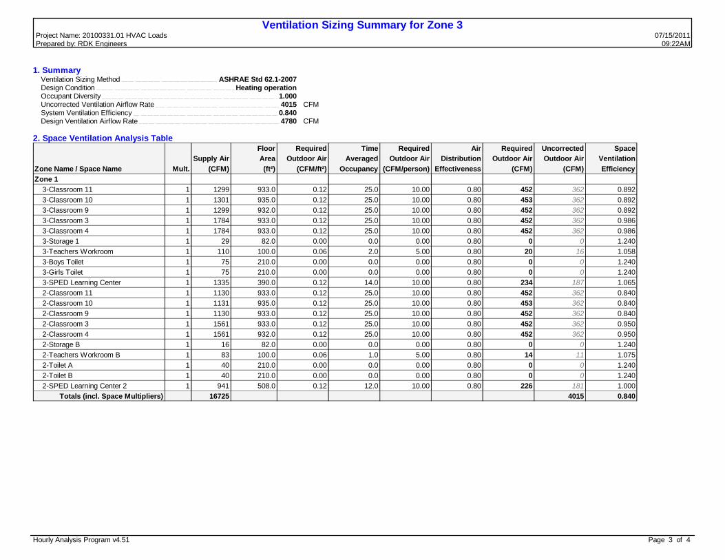
Ventilation Sizing Summary for Zone 3Project Name: 20100331.01 HVAC Loads 07/15/2011Prepared by: RDK Engineers 09:22AM
1. Summary Ventilation Sizing Method ASHRAE Std 62.1-2007 Design Condition Heating operation Occupant Diversity 1.000 Uncorrected Ventilation Airflow Rate 4015 CFM System Ventilation Efficiency 0.840 Design Ventilation Airflow Rate 4780 CFM
2. Space Ventilation Analysis TableFloor Required Time Required Air Required Uncorrected Space
Supply Air Area Outdoor Air Averaged Outdoor Air Distribution Outdoor Air Outdoor Air VentilationZone Name / Space Name Mult. (CFM) (ft²) (CFM/ft²) Occupancy (CFM/person) Effectiveness (CFM) (CFM) EfficiencyZone 1 3-Classroom 11 1 1299 933.0 0.12 25.0 10.00 0.80 452 362 0.892 3-Classroom 10 1 1301 935.0 0.12 25.0 10.00 0.80 453 362 0.892 3-Classroom 9 1 1299 932.0 0.12 25.0 10.00 0.80 452 362 0.892 3-Classroom 3 1 1784 933.0 0.12 25.0 10.00 0.80 452 362 0.986 3-Classroom 4 1 1784 933.0 0.12 25.0 10.00 0.80 452 362 0.986 3-Storage 1 1 29 82.0 0.00 0.0 0.00 0.80 0 0 1.240 3-Teachers Workroom 1 110 100.0 0.06 2.0 5.00 0.80 20 16 1.058 3-Boys Toilet 1 75 210.0 0.00 0.0 0.00 0.80 0 0 1.240 3-Girls Toilet 1 75 210.0 0.00 0.0 0.00 0.80 0 0 1.240 3-SPED Learning Center 1 1335 390.0 0.12 14.0 10.00 0.80 234 187 1.065 2-Classroom 11 1 1130 933.0 0.12 25.0 10.00 0.80 452 362 0.840 2-Classroom 10 1 1131 935.0 0.12 25.0 10.00 0.80 453 362 0.840 2-Classroom 9 1 1130 933.0 0.12 25.0 10.00 0.80 452 362 0.840 2-Classroom 3 1 1561 933.0 0.12 25.0 10.00 0.80 452 362 0.950 2-Classroom 4 1 1561 932.0 0.12 25.0 10.00 0.80 452 362 0.950 2-Storage B 1 16 82.0 0.00 0.0 0.00 0.80 0 0 1.240 2-Teachers Workroom B 1 83 100.0 0.06 1.0 5.00 0.80 14 11 1.075 2-Toilet A 1 40 210.0 0.00 0.0 0.00 0.80 0 0 1.240 2-Toilet B 1 40 210.0 0.00 0.0 0.00 0.80 0 0 1.240 2-SPED Learning Center 2 1 941 508.0 0.12 12.0 10.00 0.80 226 181 1.000
Totals (incl. Space Multipliers) 16725 4015 0.840
Hourly Analysis Program v4.51 Page 3 of 4

Air System Design Load Summary for Zone 3Project Name: 20100331.01 HVAC Loads 07/15/2011Prepared by: RDK Engineers 09:22AM
DESIGN COOLING DESIGN HEATINGCOOLING DATA AT Aug 1400 HEATING DATA AT DES HTGCOOLING OA DB / WB 89.4 °F / 71.8 °F HEATING OA DB / WB -5.0 °F / -6.2 °F
Sensible Latent Sensible LatentZONE LOADS Details (BTU/hr) (BTU/hr) Details (BTU/hr) (BTU/hr)Window & Skylight Solar Loads 1740 ft² 62162 - 1740 ft² - -Wall Transmission 3144 ft² 4460 - 3144 ft² 16447 -Roof Transmission 5658 ft² 14066 - 5658 ft² 16833 -Window Transmission 1740 ft² 12420 - 1740 ft² 84825 -Skylight Transmission 0 ft² 0 - 0 ft² 0 -Door Loads 0 ft² 0 - 0 ft² 0 -Floor Transmission 0 ft² 0 - 0 ft² 0 -Partitions 0 ft² 0 - 0 ft² 0 -Ceiling 0 ft² 0 - 0 ft² 0 -Overhead Lighting 11434 W 32763 - 0 0 -Task Lighting 10430 W 32420 - 0 0 -Electric Equipment 5550 W 17583 - 0 0 -People 279 55780 55815 0 0 0Infiltration - 15802 5921 - 82132 0Miscellaneous - 0 0 - 0 0Safety Factor 15% / 15% 37118 9260 15% 30035 0>> Total Zone Loads - 284574 70997 - 230272 0Zone Conditioning - 276452 70997 - 228005 0Plenum Wall Load 0% 0 - 0 0 -Plenum Roof Load 0% 0 - 0 0 -Plenum Lighting Load 0% 0 - 0 0 -Return Fan Load 16725 CFM 0 - 16725 CFM 0 -Ventilation Load 4780 CFM 67915 27668 4780 CFM 380187 0Supply Fan Load 16725 CFM 0 - 16725 CFM 0 -Space Fan Coil Fans - 0 - - 0 -Duct Heat Gain / Loss 0% 0 - 0% 0 ->> Total System Loads - 344367 98665 - 608192 0Central Cooling Coil - 344367 98670 - 0 0Central Heating Coil - 0 - - 608192 ->> Total Conditioning - 344367 98670 - 608192 0Key: Positive values are clg loads Positive values are htg loads
Negative values are htg loads Negative values are clg loads
Hourly Analysis Program v4.51 Page 4 of 4

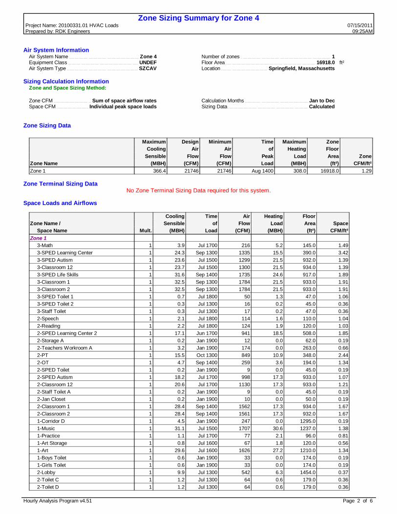
Air System Sizing Summary for Zone 4Project Name: 20100331.01 HVAC Loads 07/15/2011Prepared by: RDK Engineers 09:25AM
Air System Information Air System Name Zone 4 Equipment Class UNDEF Air System Type SZCAV
Number of zones 1Floor Area 16918.0 ft²Location Springfield, Massachusetts
Sizing Calculation InformationZone and Space Sizing Method:
Zone CFM Sum of space airflow rates Space CFM Individual peak space loads
Calculation Months Jan to DecSizing Data Calculated
Central Cooling Coil Sizing Data Total coil load 45.9 Tons Total coil load 550.7 MBH Sensible coil load 433.9 MBH Coil CFM at Aug 1400 21746 CFM Max block CFM 21746 CFM Sum of peak zone CFM 21746 CFM Sensible heat ratio 0.788 ft²/Ton 368.6 BTU/(hr-ft²) 32.6 Water flow @ 10.0 °F rise 110.20 gpm
Load occurs at Aug 1400OA DB / WB 89.4 / 71.8 °FEntering DB / WB 79.5 / 67.7 °FLeaving DB / WB 60.9 / 59.8 °FCoil ADP 58.8 °FBypass Factor 0.100Resulting RH 60 %Design supply temp. 58.0 °FZone T-stat Check 1 of 1 OKMax zone temperature deviation 0.0 °F
Central Heating Coil Sizing Data Max coil load 755.1 MBH Coil CFM at Des Htg 21746 CFM Max coil CFM 21746 CFM Water flow @ 20.0 °F drop 75.55 gpm
Load occurs at Des HtgBTU/(hr-ft²) 44.6Ent. DB / Lvg DB 50.3 / 82.7 °F
Supply Fan Sizing Data Actual max CFM 21746 CFM Standard CFM 21554 CFM Actual max CFM/ft² 1.29 CFM/ft²
Fan motor BHP 0.00 BHPFan motor kW 0.00 kWFan static 0.00 in wg
Outdoor Ventilation Air Data Design airflow CFM 5594 CFM CFM/ft² 0.33 CFM/ft²
CFM/person 18.90 CFM/person
Hourly Analysis Program v4.51 Page 1 of 6
Zone Sizing Summary for Zone 4Project Name: 20100331.01 HVAC Loads 07/15/2011Prepared by: RDK Engineers 09:25AM
Air System Information Air System Name Zone 4 Equipment Class UNDEF Air System Type SZCAV
Number of zones 1Floor Area 16918.0 ft²Location Springfield, Massachusetts
Sizing Calculation InformationZone and Space Sizing Method:
Zone CFM Sum of space airflow rates Space CFM Individual peak space loads
Calculation Months Jan to DecSizing Data Calculated
Zone Sizing Data
Maximum Design Minimum Time Maximum ZoneCooling Air Air of Heating Floor
Sensible Flow Flow Peak Load Area ZoneZone Name (MBH) (CFM) (CFM) Load (MBH) (ft²) CFM/ft²Zone 1 366.4 21746 21746 Aug 1400 308.0 16918.0 1.29
Zone Terminal Sizing DataNo Zone Terminal Sizing Data required for this system.
Space Loads and Airflows
Cooling Time Air Heating FloorZone Name / Sensible of Flow Load Area Space Space Name Mult. (MBH) Load (CFM) (MBH) (ft²) CFM/ft²Zone 1 3-Math 1 3.9 Jul 1700 216 5.2 145.0 1.49 3-SPED Learning Center 1 24.3 Sep 1300 1335 15.5 390.0 3.42 3-SPED Autism 1 23.6 Jul 1500 1299 21.5 932.0 1.39 3-Classroom 12 1 23.7 Jul 1500 1300 21.5 934.0 1.39 3-SPED Life Skills 1 31.6 Sep 1400 1735 24.6 917.0 1.89 3-Classroom 1 1 32.5 Sep 1300 1784 21.5 933.0 1.91 3-Classroom 2 1 32.5 Sep 1300 1784 21.5 933.0 1.91 3-SPED Toilet 1 1 0.7 Jul 1800 50 1.3 47.0 1.06 3-SPED Toilet 2 1 0.3 Jul 1300 16 0.2 45.0 0.36 3-Staff Toilet 1 0.3 Jul 1300 17 0.2 47.0 0.36 2-Speech 1 2.1 Jul 1800 114 1.6 110.0 1.04 2-Reading 1 2.2 Jul 1800 124 1.9 120.0 1.03 2-SPED Learning Center 2 1 17.1 Jun 1700 941 18.5 508.0 1.85 2-Storage A 1 0.2 Jan 1900 12 0.0 62.0 0.19 2-Teachers Workroom A 1 3.2 Jan 1900 174 0.0 263.0 0.66 2-PT 1 15.5 Oct 1300 849 10.9 348.0 2.44 2-OT 1 4.7 Sep 1400 259 3.6 194.0 1.34 2-SPED Toilet 1 0.2 Jan 1900 9 0.0 45.0 0.19 2-SPED Autism 1 18.2 Jul 1700 998 17.3 933.0 1.07 2-Classroom 12 1 20.6 Jul 1700 1130 17.3 933.0 1.21 2-Staff Toilet A 1 0.2 Jan 1900 9 0.0 45.0 0.19 2-Jan Closet 1 0.2 Jan 1900 10 0.0 50.0 0.19 2-Classroom 1 1 28.4 Sep 1400 1562 17.3 934.0 1.67 2-Classroom 2 1 28.4 Sep 1400 1561 17.3 932.0 1.67 1-Corridor D 1 4.5 Jan 1900 247 0.0 1295.0 0.19 1-Music 1 31.1 Jul 1500 1707 30.6 1237.0 1.38 1-Practice 1 1.1 Jul 1700 77 2.1 96.0 0.81 1-Art Storage 1 0.8 Jul 1600 67 1.8 120.0 0.56 1-Art 1 29.6 Jul 1600 1626 27.2 1210.0 1.34 1-Boys Toilet 1 0.6 Jan 1900 33 0.0 174.0 0.19 1-Girls Toilet 1 0.6 Jan 1900 33 0.0 174.0 0.19 2-Lobby 1 9.9 Jul 1300 542 6.3 1454.0 0.37 2-Toilet C 1 1.2 Jul 1300 64 0.6 179.0 0.36 2-Toilet D 1 1.2 Jul 1300 64 0.6 179.0 0.36
Hourly Analysis Program v4.51 Page 2 of 6

Zone Sizing Summary for Zone 4Project Name: 20100331.01 HVAC Loads 07/15/2011Prepared by: RDK Engineers 09:25AM
Hourly Analysis Program v4.51 Page 3 of 6

Ventilation Sizing Summary for Zone 4Project Name: 20100331.01 HVAC Loads 07/15/2011Prepared by: RDK Engineers 09:25AM
1. Summary Ventilation Sizing Method ASHRAE Std 62.1-2007 Design Condition Heating operation Occupant Diversity 1.000 Uncorrected Ventilation Airflow Rate 4517 CFM System Ventilation Efficiency 0.807 Design Ventilation Airflow Rate 5594 CFM
2. Space Ventilation Analysis TableFloor Required Time Required Air Required Uncorrected Space
Supply Air Area Outdoor Air Averaged Outdoor Air Distribution Outdoor Air Outdoor Air VentilationZone Name / Space Name Mult. (CFM) (ft²) (CFM/ft²) Occupancy (CFM/person) Effectiveness (CFM) (CFM) EfficiencyZone 1 3-Math 1 216 145.0 0.12 1.0 10.00 0.80 34 27 1.049 3-SPED Learning Center 1 1335 390.0 0.12 14.0 10.00 0.80 234 187 1.033 3-SPED Autism 1 1299 932.0 0.12 25.0 10.00 0.80 452 362 0.859 3-Classroom 12 1 1300 934.0 0.12 25.0 10.00 0.80 453 362 0.859 3-SPED Life Skills 1 1735 917.0 0.12 20.0 10.00 0.80 388 310 0.984 3-Classroom 1 1 1784 933.0 0.12 25.0 10.00 0.80 452 362 0.954 3-Classroom 2 1 1784 933.0 0.12 25.0 10.00 0.80 452 362 0.954 3-SPED Toilet 1 1 50 47.0 0.00 0.0 0.00 0.80 0 0 1.208 3-SPED Toilet 2 1 16 45.0 0.00 0.0 0.00 0.80 0 0 1.208 3-Staff Toilet 1 17 47.0 0.00 0.0 0.00 0.80 0 0 1.208 2-Speech 1 114 110.0 0.12 1.0 10.00 0.80 29 23 0.953 2-Reading 1 124 120.0 0.12 1.0 10.00 0.80 31 24 0.961 2-SPED Learning Center 2 1 941 508.0 0.12 12.0 10.00 0.80 226 181 0.967 2-Storage A 1 12 62.0 0.00 0.0 0.00 0.80 0 0 1.208 2-Teachers Workroom A 1 174 263.0 0.06 3.0 5.00 0.80 38 31 0.986 2-PT 1 849 348.0 0.06 3.0 5.00 0.80 45 36 1.155 2-OT 1 259 194.0 0.06 1.0 5.00 0.80 21 17 1.128 2-SPED Toilet 1 9 45.0 0.00 0.0 0.00 0.80 0 0 1.208 2-SPED Autism 1 998 933.0 0.12 15.0 10.00 0.80 327 262 0.880 2-Classroom 12 1 1130 933.0 0.12 25.0 10.00 0.80 452 362 0.807 2-Staff Toilet A 1 9 45.0 0.00 0.0 0.00 0.80 0 0 1.208 2-Jan Closet 1 10 50.0 0.00 0.0 0.00 0.80 0 0 1.208 2-Classroom 1 1 1562 934.0 0.12 25.0 10.00 0.80 453 362 0.918 2-Classroom 2 1 1561 932.0 0.12 25.0 10.00 0.80 452 362 0.918 1-Corridor D 1 247 1295.0 0.00 0.0 0.00 0.80 0 0 1.208 1-Music 1 1707 1237.0 0.06 25.0 10.00 0.80 405 324 0.970 1-Practice 1 77 96.0 0.06 0.0 10.00 0.80 7 6 1.115 1-Art Storage 1 67 120.0 0.00 0.0 0.00 0.80 0 0 1.208 1-Art 1 1626 1210.0 0.18 25.0 10.00 0.80 585 468 0.848 1-Boys Toilet 1 33 174.0 0.00 0.0 0.00 0.80 0 0 1.208 1-Girls Toilet 1 33 174.0 0.00 0.0 0.00 0.80 0 0 1.208 2-Lobby 1 542 1454.0 0.06 0.0 0.00 0.80 109 87 1.006 2-Toilet C 1 64 179.0 0.00 0.0 0.00 0.80 0 0 1.208
Hourly Analysis Program v4.51 Page 4 of 6

Ventilation Sizing Summary for Zone 4Project Name: 20100331.01 HVAC Loads 07/15/2011Prepared by: RDK Engineers 09:25AM
2-Toilet D 1 64 179.0 0.00 0.0 0.00 0.80 0 0 1.208Totals (incl. Space Multipliers) 21746 4517 0.807
Hourly Analysis Program v4.51 Page 5 of 6

Air System Design Load Summary for Zone 4Project Name: 20100331.01 HVAC Loads 07/15/2011Prepared by: RDK Engineers 09:25AM
DESIGN COOLING DESIGN HEATINGCOOLING DATA AT Aug 1400 HEATING DATA AT DES HTGCOOLING OA DB / WB 89.4 °F / 71.8 °F HEATING OA DB / WB -5.0 °F / -6.2 °F
Sensible Latent Sensible LatentZONE LOADS Details (BTU/hr) (BTU/hr) Details (BTU/hr) (BTU/hr)Window & Skylight Solar Loads 2146 ft² 86318 - 2146 ft² - -Wall Transmission 6386 ft² 9051 - 6386 ft² 33407 -Roof Transmission 7334 ft² 18233 - 7334 ft² 21819 -Window Transmission 2146 ft² 15318 - 2146 ft² 104618 -Skylight Transmission 0 ft² 0 - 0 ft² 0 -Door Loads 36 ft² 119 - 36 ft² 810 -Floor Transmission 4306 ft² 0 - 4306 ft² 0 -Partitions 0 ft² 0 - 0 ft² 0 -Ceiling 0 ft² 0 - 0 ft² 0 -Overhead Lighting 16918 W 48476 - 0 0 -Task Lighting 13002 W 40414 - 0 0 -Electric Equipment 6300 W 19959 - 0 0 -People 296 60063 65610 0 0 0Infiltration - 20621 7744 - 107180 0Miscellaneous - 0 0 - 0 0Safety Factor 15% / 15% 47786 11003 15% 40175 0>> Total Zone Loads - 366360 84357 - 308008 0Zone Conditioning - 353922 84357 - 309680 0Plenum Wall Load 0% 0 - 0 0 -Plenum Roof Load 0% 0 - 0 0 -Plenum Lighting Load 0% 0 - 0 0 -Return Fan Load 21746 CFM 0 - 21746 CFM 0 -Ventilation Load 5594 CFM 79935 32433 5594 CFM 445422 0Supply Fan Load 21746 CFM 0 - 21746 CFM 0 -Space Fan Coil Fans - 0 - - 0 -Duct Heat Gain / Loss 0% 0 - 0% 0 ->> Total System Loads - 433857 116791 - 755102 0Central Cooling Coil - 433857 116848 - 0 0Central Heating Coil - 0 - - 755102 ->> Total Conditioning - 433857 116848 - 755102 0Key: Positive values are clg loads Positive values are htg loads
Negative values are htg loads Negative values are clg loads
Hourly Analysis Program v4.51 Page 6 of 6

Air System Sizing Summary for Zone 5Project Name: 20100331.01 HVAC Loads 07/15/2011Prepared by: RDK Engineers 09:26AM
Air System Information Air System Name Zone 5 Equipment Class UNDEF Air System Type SZCAV
Number of zones 1Floor Area 3548.0 ft²Location Springfield, Massachusetts
Sizing Calculation InformationZone and Space Sizing Method:
Zone CFM Sum of space airflow rates Space CFM Individual peak space loads
Calculation Months Jan to DecSizing Data Calculated
Central Cooling Coil Sizing Data Total coil load 12.7 Tons Total coil load 152.0 MBH Sensible coil load 126.1 MBH Coil CFM at Jul 1600 6201 CFM Max block CFM 6201 CFM Sum of peak zone CFM 6201 CFM Sensible heat ratio 0.830 ft²/Ton 280.1 BTU/(hr-ft²) 42.8 Water flow @ 10.0 °F rise 30.41 gpm
Load occurs at Jul 1600OA DB / WB 89.4 / 71.8 °FEntering DB / WB 79.2 / 66.8 °FLeaving DB / WB 60.2 / 59.0 °FCoil ADP 58.1 °FBypass Factor 0.100Resulting RH 56 %Design supply temp. 58.0 °FZone T-stat Check 1 of 1 OKMax zone temperature deviation 0.0 °F
Central Heating Coil Sizing Data Max coil load 176.1 MBH Coil CFM at Des Htg 6201 CFM Max coil CFM 6201 CFM Water flow @ 20.0 °F drop 17.62 gpm
Load occurs at Des HtgBTU/(hr-ft²) 49.6Ent. DB / Lvg DB 53.8 / 80.3 °F
Supply Fan Sizing Data Actual max CFM 6201 CFM Standard CFM 6147 CFM Actual max CFM/ft² 1.75 CFM/ft²
Fan motor BHP 0.00 BHPFan motor kW 0.00 kWFan static 0.00 in wg
Outdoor Ventilation Air Data Design airflow CFM 1288 CFM CFM/ft² 0.36 CFM/ft²
CFM/person 26.30 CFM/person
Hourly Analysis Program v4.51 Page 1 of 4

Zone Sizing Summary for Zone 5Project Name: 20100331.01 HVAC Loads 07/15/2011Prepared by: RDK Engineers 09:26AM
Air System Information Air System Name Zone 5 Equipment Class UNDEF Air System Type SZCAV
Number of zones 1Floor Area 3548.0 ft²Location Springfield, Massachusetts
Sizing Calculation InformationZone and Space Sizing Method:
Zone CFM Sum of space airflow rates Space CFM Individual peak space loads
Calculation Months Jan to DecSizing Data Calculated
Zone Sizing Data
Maximum Design Minimum Time Maximum ZoneCooling Air Air of Heating Floor
Sensible Flow Flow Peak Load Area ZoneZone Name (MBH) (CFM) (CFM) Load (MBH) (ft²) CFM/ft²Zone 1 112.4 6201 6201 Jul 1700 75.6 3548.0 1.75
Zone Terminal Sizing DataNo Zone Terminal Sizing Data required for this system.
Space Loads and Airflows
Cooling Time Air Heating FloorZone Name / Sensible of Flow Load Area Space Space Name Mult. (MBH) Load (CFM) (MBH) (ft²) CFM/ft²Zone 1 1-Media Center 1 94.2 Jul 1600 5176 75.6 2600.0 1.99 1-Small Group 1 14.9 Jan 1900 821 0.0 652.0 1.26 1-Office D 1 1.7 Jan 1900 94 0.0 128.0 0.74 1-Work 1 2.0 Jan 1900 110 0.0 168.0 0.65
Hourly Analysis Program v4.51 Page 2 of 4

Ventilation Sizing Summary for Zone 5Project Name: 20100331.01 HVAC Loads 07/15/2011Prepared by: RDK Engineers 09:26AM
1. Summary Ventilation Sizing Method ASHRAE Std 62.1-2007 Design Condition Heating operation Occupant Diversity 1.000 Uncorrected Ventilation Airflow Rate 888 CFM System Ventilation Efficiency 0.689 Design Ventilation Airflow Rate 1288 CFM
2. Space Ventilation Analysis TableFloor Required Time Required Air Required Uncorrected Space
Supply Air Area Outdoor Air Averaged Outdoor Air Distribution Outdoor Air Outdoor Air VentilationZone Name / Space Name Mult. (CFM) (ft²) (CFM/ft²) Occupancy (CFM/person) Effectiveness (CFM) (CFM) EfficiencyZone 1 1-Media Center 1 5176 2600.0 0.12 25.0 10.00 0.80 703 562 1.007 1-Small Group 1 821 652.0 0.12 22.0 10.00 0.80 373 298 0.689 1-Office D 1 94 128.0 0.06 1.0 5.00 0.80 16 13 0.975 1-Work 1 110 168.0 0.06 1.0 5.00 0.80 19 15 0.972
Totals (incl. Space Multipliers) 6201 888 0.689
Hourly Analysis Program v4.51 Page 3 of 4

Air System Design Load Summary for Zone 5Project Name: 20100331.01 HVAC Loads 07/15/2011Prepared by: RDK Engineers 09:26AM
DESIGN COOLING DESIGN HEATINGCOOLING DATA AT Jul 1600 HEATING DATA AT DES HTGCOOLING OA DB / WB 89.4 °F / 71.8 °F HEATING OA DB / WB -5.0 °F / -6.2 °F
Sensible Latent Sensible LatentZONE LOADS Details (BTU/hr) (BTU/hr) Details (BTU/hr) (BTU/hr)Window & Skylight Solar Loads 838 ft² 29200 - 838 ft² - -Wall Transmission 94 ft² 133 - 94 ft² 492 -Roof Transmission 0 ft² 0 - 0 ft² 0 -Window Transmission 838 ft² 6227 - 838 ft² 40853 -Skylight Transmission 0 ft² 0 - 0 ft² 0 -Door Loads 0 ft² 0 - 0 ft² 0 -Floor Transmission 3548 ft² 0 - 3548 ft² 0 -Partitions 0 ft² 0 - 0 ft² 0 -Ceiling 0 ft² 0 - 0 ft² 0 -Overhead Lighting 3548 W 10413 - 0 0 -Task Lighting 3548 W 11165 - 0 0 -Electric Equipment 8104 W 25926 - 0 0 -People 49 9999 9935 0 0 0Infiltration - 4686 2676 - 24353 0Miscellaneous - 0 0 - 0 0Safety Factor 15% / 15% 14662 1892 15% 9855 0>> Total Zone Loads - 112410 14502 - 75552 0Zone Conditioning - 108241 14502 - 73756 0Plenum Wall Load 0% 0 - 0 0 -Plenum Roof Load 0% 0 - 0 0 -Plenum Lighting Load 0% 0 - 0 0 -Return Fan Load 6201 CFM 0 - 6201 CFM 0 -Ventilation Load 1288 CFM 17867 11363 1288 CFM 102325 0Supply Fan Load 6201 CFM 0 - 6201 CFM 0 -Space Fan Coil Fans - 0 - - 0 -Duct Heat Gain / Loss 0% 0 - 0% 0 ->> Total System Loads - 126109 25865 - 176080 0Central Cooling Coil - 126108 25878 - 0 0Central Heating Coil - 0 - - 176080 ->> Total Conditioning - 126108 25878 - 176080 0Key: Positive values are clg loads Positive values are htg loads
Negative values are htg loads Negative values are clg loads
Hourly Analysis Program v4.51 Page 4 of 4

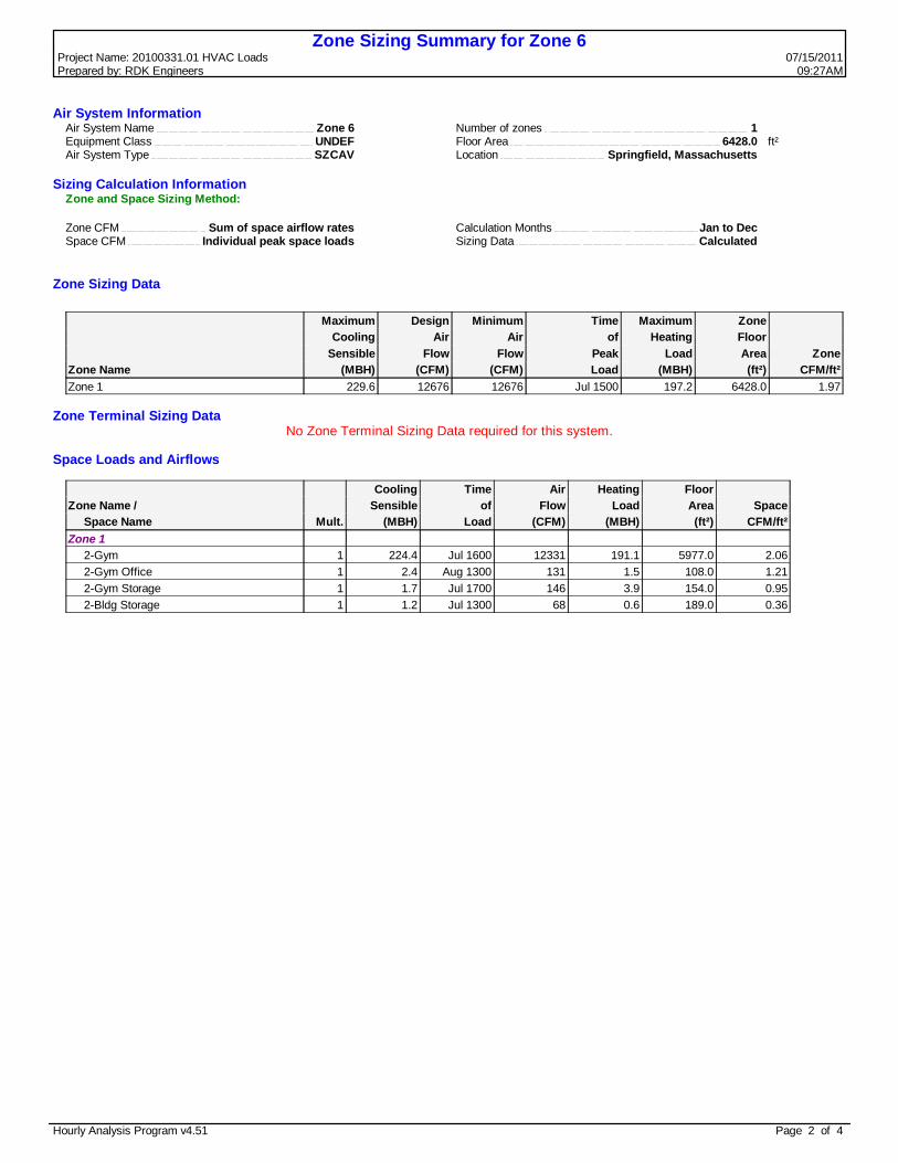
Air System Sizing Summary for Zone 6Project Name: 20100331.01 HVAC Loads 07/15/2011Prepared by: RDK Engineers 09:27AM
Air System Information Air System Name Zone 6 Equipment Class UNDEF Air System Type SZCAV
Number of zones 1Floor Area 6428.0 ft²Location Springfield, Massachusetts
Sizing Calculation InformationZone and Space Sizing Method:
Zone CFM Sum of space airflow rates Space CFM Individual peak space loads
Calculation Months Jan to DecSizing Data Calculated
Central Cooling Coil Sizing Data Total coil load 37.1 Tons Total coil load 445.2 MBH Sensible coil load 245.1 MBH Coil CFM at Jul 1500 12676 CFM Max block CFM 12676 CFM Sum of peak zone CFM 12676 CFM Sensible heat ratio 0.550 ft²/Ton 173.2 BTU/(hr-ft²) 69.3 Water flow @ 10.0 °F rise 89.10 gpm
Load occurs at Jul 1500OA DB / WB 90.0 / 72.0 °FEntering DB / WB 78.4 / 70.4 °FLeaving DB / WB 60.4 / 59.7 °FCoil ADP 58.4 °FBypass Factor 0.100Resulting RH 73 %Design supply temp. 58.0 °FZone T-stat Check 0 of 1 OKMax zone temperature deviation 0.0 °F
Central Heating Coil Sizing Data Max coil load 333.4 MBH Coil CFM at Des Htg 12676 CFM Max coil CFM 12676 CFM Water flow @ 20.0 °F drop 33.36 gpm
Load occurs at Des HtgBTU/(hr-ft²) 51.9Ent. DB / Lvg DB 58.5 / 83.1 °F
Supply Fan Sizing Data Actual max CFM 12676 CFM Standard CFM 12564 CFM Actual max CFM/ft² 1.97 CFM/ft²
Fan motor BHP 0.00 BHPFan motor kW 0.00 kWFan static 0.00 in wg
Outdoor Ventilation Air Data Design airflow CFM 1787 CFM CFM/ft² 0.28 CFM/ft²
CFM/person 9.87 CFM/person
Hourly Analysis Program v4.51 Page 1 of 4
Zone Sizing Summary for Zone 6Project Name: 20100331.01 HVAC Loads 07/15/2011Prepared by: RDK Engineers 09:27AM
Air System Information Air System Name Zone 6 Equipment Class UNDEF Air System Type SZCAV
Number of zones 1Floor Area 6428.0 ft²Location Springfield, Massachusetts
Sizing Calculation InformationZone and Space Sizing Method:
Zone CFM Sum of space airflow rates Space CFM Individual peak space loads
Calculation Months Jan to DecSizing Data Calculated
Zone Sizing Data
Maximum Design Minimum Time Maximum ZoneCooling Air Air of Heating Floor
Sensible Flow Flow Peak Load Area ZoneZone Name (MBH) (CFM) (CFM) Load (MBH) (ft²) CFM/ft²Zone 1 229.6 12676 12676 Jul 1500 197.2 6428.0 1.97
Zone Terminal Sizing DataNo Zone Terminal Sizing Data required for this system.
Space Loads and Airflows
Cooling Time Air Heating FloorZone Name / Sensible of Flow Load Area Space Space Name Mult. (MBH) Load (CFM) (MBH) (ft²) CFM/ft²Zone 1 2-Gym 1 224.4 Jul 1600 12331 191.1 5977.0 2.06 2-Gym Office 1 2.4 Aug 1300 131 1.5 108.0 1.21 2-Gym Storage 1 1.7 Jul 1700 146 3.9 154.0 0.95 2-Bldg Storage 1 1.2 Jul 1300 68 0.6 189.0 0.36
Hourly Analysis Program v4.51 Page 2 of 4

Ventilation Sizing Summary for Zone 6Project Name: 20100331.01 HVAC Loads 07/15/2011Prepared by: RDK Engineers 09:27AM
1. Summary Ventilation Sizing Method ASHRAE Std 62.1-2007 Design Condition Heating operation Occupant Diversity 1.000 Uncorrected Ventilation Airflow Rate 1720 CFM System Ventilation Efficiency 0.962 Design Ventilation Airflow Rate 1787 CFM
2. Space Ventilation Analysis TableFloor Required Time Required Air Required Uncorrected Space
Supply Air Area Outdoor Air Averaged Outdoor Air Distribution Outdoor Air Outdoor Air VentilationZone Name / Space Name Mult. (CFM) (ft²) (CFM/ft²) Occupancy (CFM/person) Effectiveness (CFM) (CFM) EfficiencyZone 1 2-Gym 1 12331 5977.0 0.06 180.0 7.50 0.80 2136 1709 0.962 2-Gym Office 1 131 108.0 0.06 1.0 5.00 0.80 14 11 1.026 2-Gym Storage 1 146 154.0 0.00 0.0 0.00 0.80 0 0 1.136 2-Bldg Storage 1 68 189.0 0.00 0.0 0.00 0.80 0 0 1.136
Totals (incl. Space Multipliers) 12676 1720 0.962
Hourly Analysis Program v4.51 Page 3 of 4

Air System Design Load Summary for Zone 6Project Name: 20100331.01 HVAC Loads 07/15/2011Prepared by: RDK Engineers 09:27AM
DESIGN COOLING DESIGN HEATINGCOOLING DATA AT Jul 1500 HEATING DATA AT DES HTGCOOLING OA DB / WB 90.0 °F / 72.0 °F HEATING OA DB / WB -5.0 °F / -6.2 °F
Sensible Latent Sensible LatentZONE LOADS Details (BTU/hr) (BTU/hr) Details (BTU/hr) (BTU/hr)Window & Skylight Solar Loads 130 ft² 6235 - 130 ft² - -Wall Transmission 5960 ft² 11062 - 5960 ft² 31179 -Roof Transmission 6428 ft² 15870 - 6428 ft² 19123 -Window Transmission 130 ft² 980 - 130 ft² 6338 -Skylight Transmission 0 ft² 0 - 0 ft² 0 -Door Loads 72 ft² 250 - 72 ft² 1620 -Floor Transmission 0 ft² 0 - 0 ft² 0 -Partitions 0 ft² 0 - 0 ft² 0 -Ceiling 0 ft² 0 - 0 ft² 0 -Overhead Lighting 6428 W 18649 - 0 0 -Task Lighting 108 W 338 - 0 0 -Electric Equipment 6127 W 19509 - 0 0 -People 181 104104 196405 0 0 0Infiltration - 22641 -10642 - 113205 0Miscellaneous - 0 0 - 0 0Safety Factor 15% / 15% 29946 27864 15% 25720 0>> Total Zone Loads - 229586 213627 - 197184 0Zone Conditioning - 219317 213627 - 191973 0Plenum Wall Load 0% 0 - 0 0 -Plenum Roof Load 0% 0 - 0 0 -Plenum Lighting Load 0% 0 - 0 0 -Return Fan Load 12676 CFM 0 - 12676 CFM 0 -Ventilation Load 1787 CFM 25743 -13497 1787 CFM 141462 0Supply Fan Load 12676 CFM 0 - 12676 CFM 0 -Space Fan Coil Fans - 0 - - 0 -Duct Heat Gain / Loss 0% 0 - 0% 0 ->> Total System Loads - 245060 200130 - 333435 0Central Cooling Coil - 245060 200190 - 0 0Central Heating Coil - 0 - - 333435 ->> Total Conditioning - 245060 200190 - 333435 0Key: Positive values are clg loads Positive values are htg loads
Negative values are htg loads Negative values are clg loads
Hourly Analysis Program v4.51 Page 4 of 4
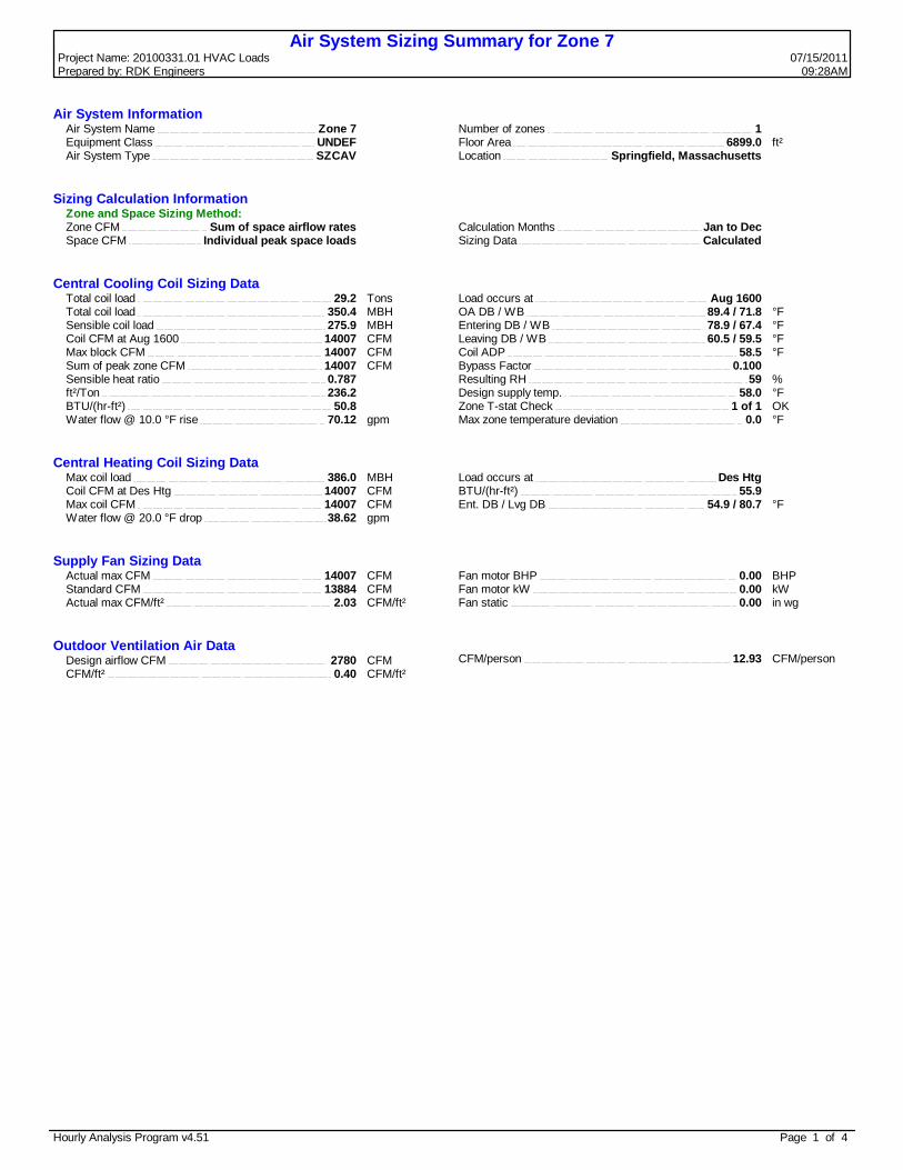
Air System Sizing Summary for Zone 7Project Name: 20100331.01 HVAC Loads 07/15/2011Prepared by: RDK Engineers 09:28AM
Air System Information Air System Name Zone 7 Equipment Class UNDEF Air System Type SZCAV
Number of zones 1Floor Area 6899.0 ft²Location Springfield, Massachusetts
Sizing Calculation InformationZone and Space Sizing Method:
Zone CFM Sum of space airflow rates Space CFM Individual peak space loads
Calculation Months Jan to DecSizing Data Calculated
Central Cooling Coil Sizing Data Total coil load 29.2 Tons Total coil load 350.4 MBH Sensible coil load 275.9 MBH Coil CFM at Aug 1600 14007 CFM Max block CFM 14007 CFM Sum of peak zone CFM 14007 CFM Sensible heat ratio 0.787 ft²/Ton 236.2 BTU/(hr-ft²) 50.8 Water flow @ 10.0 °F rise 70.12 gpm
Load occurs at Aug 1600OA DB / WB 89.4 / 71.8 °FEntering DB / WB 78.9 / 67.4 °FLeaving DB / WB 60.5 / 59.5 °FCoil ADP 58.5 °FBypass Factor 0.100Resulting RH 59 %Design supply temp. 58.0 °FZone T-stat Check 1 of 1 OKMax zone temperature deviation 0.0 °F
Central Heating Coil Sizing Data Max coil load 386.0 MBH Coil CFM at Des Htg 14007 CFM Max coil CFM 14007 CFM Water flow @ 20.0 °F drop 38.62 gpm
Load occurs at Des HtgBTU/(hr-ft²) 55.9Ent. DB / Lvg DB 54.9 / 80.7 °F
Supply Fan Sizing Data Actual max CFM 14007 CFM Standard CFM 13884 CFM Actual max CFM/ft² 2.03 CFM/ft²
Fan motor BHP 0.00 BHPFan motor kW 0.00 kWFan static 0.00 in wg
Outdoor Ventilation Air Data Design airflow CFM 2780 CFM CFM/ft² 0.40 CFM/ft²
CFM/person 12.93 CFM/person
Hourly Analysis Program v4.51 Page 1 of 4

Zone Sizing Summary for Zone 7Project Name: 20100331.01 HVAC Loads 07/15/2011Prepared by: RDK Engineers 09:28AM
Air System Information Air System Name Zone 7 Equipment Class UNDEF Air System Type SZCAV
Number of zones 1Floor Area 6899.0 ft²Location Springfield, Massachusetts
Sizing Calculation InformationZone and Space Sizing Method:
Zone CFM Sum of space airflow rates Space CFM Individual peak space loads
Calculation Months Jan to DecSizing Data Calculated
Zone Sizing Data
Maximum Design Minimum Time Maximum ZoneCooling Air Air of Heating Floor
Sensible Flow Flow Peak Load Area ZoneZone Name (MBH) (CFM) (CFM) Load (MBH) (ft²) CFM/ft²Zone 1 250.4 14007 14007 Sep 1400 158.2 6899.0 2.03
Zone Terminal Sizing DataNo Zone Terminal Sizing Data required for this system.
Space Loads and Airflows
Cooling Time Air Heating FloorZone Name / Sensible of Flow Load Area Space Space Name Mult. (MBH) Load (CFM) (MBH) (ft²) CFM/ft²Zone 1 1-Cafeteria 1 217.6 Sep 1400 11958 139.8 4065.0 2.94 1-Platform 1 18.5 Jan 1900 1017 0.0 947.0 1.07 1-Storage C 1 0.7 Jan 1900 41 0.0 213.0 0.19 1-Staff Toilet B 1 0.2 Jan 1900 10 0.0 52.0 0.19 1-Staff Toilet C 1 0.2 Jan 1900 10 0.0 52.0 0.19 1-Corridor E 1 1.8 Jan 1900 97 0.0 508.0 0.19 1-Custodial Office 1 2.1 Aug 1600 113 1.9 90.0 1.26 1-Custodial Workshop 1 7.8 Jul 1600 426 8.6 587.0 0.73 1-Dry Storage 1 2.1 Jul 1600 214 5.7 285.0 0.75 1-Kitchen Office 1 2.2 Aug 1600 122 2.2 100.0 1.22
Hourly Analysis Program v4.51 Page 2 of 4
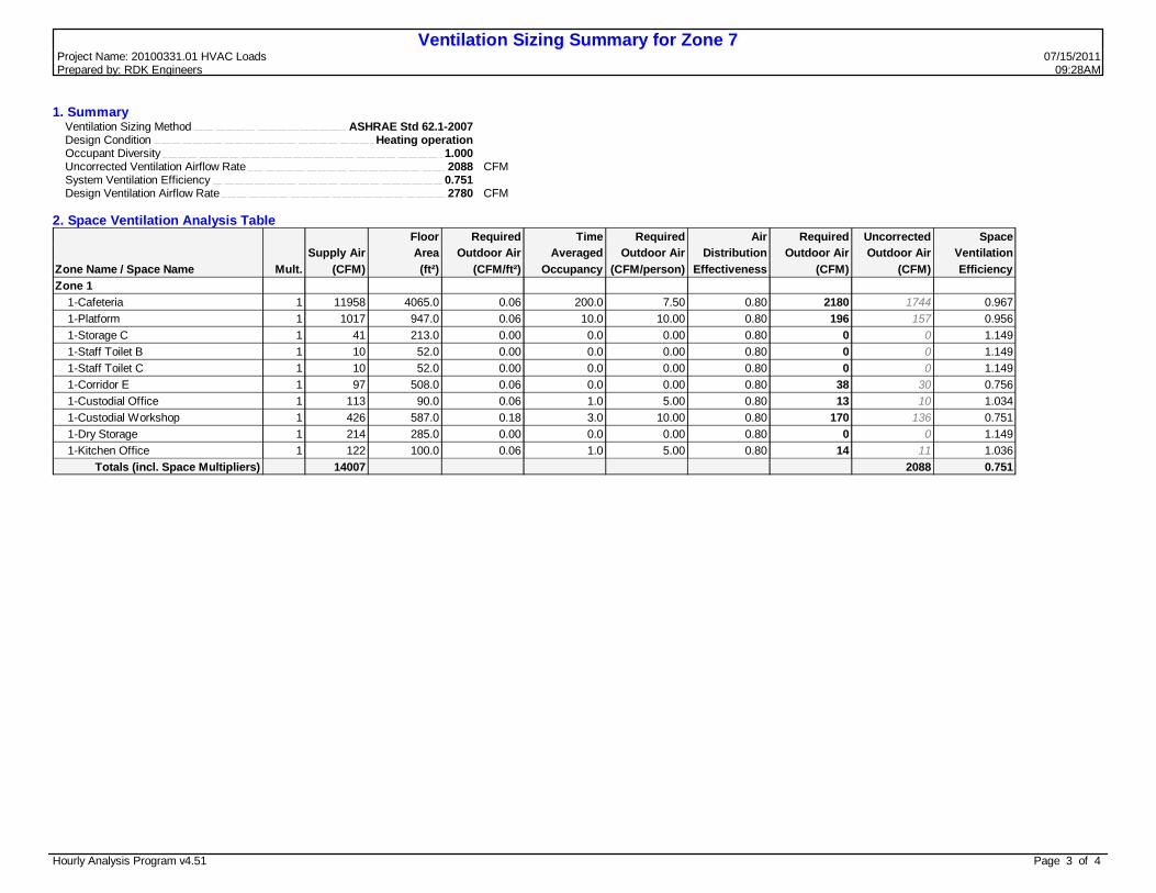
Ventilation Sizing Summary for Zone 7Project Name: 20100331.01 HVAC Loads 07/15/2011Prepared by: RDK Engineers 09:28AM
1. Summary Ventilation Sizing Method ASHRAE Std 62.1-2007 Design Condition Heating operation Occupant Diversity 1.000 Uncorrected Ventilation Airflow Rate 2088 CFM System Ventilation Efficiency 0.751 Design Ventilation Airflow Rate 2780 CFM
2. Space Ventilation Analysis TableFloor Required Time Required Air Required Uncorrected Space
Supply Air Area Outdoor Air Averaged Outdoor Air Distribution Outdoor Air Outdoor Air VentilationZone Name / Space Name Mult. (CFM) (ft²) (CFM/ft²) Occupancy (CFM/person) Effectiveness (CFM) (CFM) EfficiencyZone 1 1-Cafeteria 1 11958 4065.0 0.06 200.0 7.50 0.80 2180 1744 0.967 1-Platform 1 1017 947.0 0.06 10.0 10.00 0.80 196 157 0.956 1-Storage C 1 41 213.0 0.00 0.0 0.00 0.80 0 0 1.149 1-Staff Toilet B 1 10 52.0 0.00 0.0 0.00 0.80 0 0 1.149 1-Staff Toilet C 1 10 52.0 0.00 0.0 0.00 0.80 0 0 1.149 1-Corridor E 1 97 508.0 0.06 0.0 0.00 0.80 38 30 0.756 1-Custodial Office 1 113 90.0 0.06 1.0 5.00 0.80 13 10 1.034 1-Custodial Workshop 1 426 587.0 0.18 3.0 10.00 0.80 170 136 0.751 1-Dry Storage 1 214 285.0 0.00 0.0 0.00 0.80 0 0 1.149 1-Kitchen Office 1 122 100.0 0.06 1.0 5.00 0.80 14 11 1.036
Totals (incl. Space Multipliers) 14007 2088 0.751
Hourly Analysis Program v4.51 Page 3 of 4

Air System Design Load Summary for Zone 7Project Name: 20100331.01 HVAC Loads 07/15/2011Prepared by: RDK Engineers 09:28AM
DESIGN COOLING DESIGN HEATINGCOOLING DATA AT Aug 1600 HEATING DATA AT DES HTGCOOLING OA DB / WB 89.4 °F / 71.8 °F HEATING OA DB / WB -5.0 °F / -6.2 °F
Sensible Latent Sensible LatentZONE LOADS Details (BTU/hr) (BTU/hr) Details (BTU/hr) (BTU/hr)Window & Skylight Solar Loads 1597 ft² 92856 - 1597 ft² - -Wall Transmission 1361 ft² 2160 - 1361 ft² 7118 -Roof Transmission 1260 ft² 2253 - 1260 ft² 3749 -Window Transmission 1597 ft² 11867 - 1597 ft² 77854 -Skylight Transmission 0 ft² 0 - 0 ft² 0 -Door Loads 36 ft² 123 - 36 ft² 810 -Floor Transmission 6899 ft² 0 - 6899 ft² 0 -Partitions 0 ft² 0 - 0 ft² 0 -Ceiling 0 ft² 0 - 0 ft² 0 -Overhead Lighting 6899 W 20247 - 0 0 -Task Lighting 1137 W 3578 - 0 0 -Electric Equipment 7613 W 24355 - 0 0 -People 215 44835 46325 0 0 0Infiltration - 9240 3666 - 48023 0Miscellaneous - 0 0 - 0 0Safety Factor 15% / 15% 31727 7499 15% 20633 0>> Total Zone Loads - 243242 57489 - 158186 0Zone Conditioning - 236959 57489 - 163496 0Plenum Wall Load 0% 0 - 0 0 -Plenum Roof Load 0% 0 - 0 0 -Plenum Lighting Load 0% 0 - 0 0 -Return Fan Load 14007 CFM 0 - 14007 CFM 0 -Ventilation Load 2780 CFM 38919 17030 2780 CFM 222477 0Supply Fan Load 14007 CFM 0 - 14007 CFM 0 -Space Fan Coil Fans - 0 - - 0 -Duct Heat Gain / Loss 0% 0 - 0% 0 ->> Total System Loads - 275879 74519 - 385973 0Central Cooling Coil - 275879 74557 - 0 0Central Heating Coil - 0 - - 385973 ->> Total Conditioning - 275879 74557 - 385973 0Key: Positive values are clg loads Positive values are htg loads
Negative values are htg loads Negative values are clg loads
Hourly Analysis Program v4.51 Page 4 of 4

Air System Sizing Summary for Zone 8Project Name: 20100331.01 HVAC Loads 07/15/2011Prepared by: RDK Engineers 09:28AM
Air System Information Air System Name Zone 8 Equipment Class UNDEF Air System Type SZCAV
Number of zones 1Floor Area 1125.0 ft²Location Springfield, Massachusetts
Sizing Calculation InformationZone and Space Sizing Method:
Zone CFM Sum of space airflow rates Space CFM Individual peak space loads
Calculation Months Jan to DecSizing Data Calculated
Central Cooling Coil Sizing Data Total coil load 2.4 Tons Total coil load 28.7 MBH Sensible coil load 22.0 MBH Coil CFM at Aug 1600 959 CFM Max block CFM 959 CFM Sum of peak zone CFM 959 CFM Sensible heat ratio 0.767 ft²/Ton 469.6 BTU/(hr-ft²) 25.6 Water flow @ 10.0 °F rise 5.75 gpm
Load occurs at Aug 1600OA DB / WB 89.4 / 71.8 °FEntering DB / WB 80.9 / 67.8 °FLeaving DB / WB 59.5 / 58.3 °FCoil ADP 57.1 °FBypass Factor 0.100Resulting RH 57 %Design supply temp. 58.0 °FZone T-stat Check 1 of 1 OKMax zone temperature deviation 0.0 °F
Central Heating Coil Sizing Data Max coil load 40.9 MBH Coil CFM at Des Htg 959 CFM Max coil CFM 959 CFM Water flow @ 20.0 °F drop 4.09 gpm
Load occurs at Des HtgBTU/(hr-ft²) 36.3Ent. DB / Lvg DB 42.4 / 82.2 °F
Supply Fan Sizing Data Actual max CFM 959 CFM Standard CFM 951 CFM Actual max CFM/ft² 0.85 CFM/ft²
Fan motor BHP 0.00 BHPFan motor kW 0.00 kWFan static 0.00 in wg
Outdoor Ventilation Air Data Design airflow CFM 347 CFM CFM/ft² 0.31 CFM/ft²
CFM/person 34.69 CFM/person
Hourly Analysis Program v4.51 Page 1 of 4

Zone Sizing Summary for Zone 8Project Name: 20100331.01 HVAC Loads 07/15/2011Prepared by: RDK Engineers 09:28AM
Air System Information Air System Name Zone 8 Equipment Class UNDEF Air System Type SZCAV
Number of zones 1Floor Area 1125.0 ft²Location Springfield, Massachusetts
Sizing Calculation InformationZone and Space Sizing Method:
Zone CFM Sum of space airflow rates Space CFM Individual peak space loads
Calculation Months Jan to DecSizing Data Calculated
Zone Sizing Data
Maximum Design Minimum Time Maximum ZoneCooling Air Air of Heating Floor
Sensible Flow Flow Peak Load Area ZoneZone Name (MBH) (CFM) (CFM) Load (MBH) (ft²) CFM/ft²Zone 1 17.5 959 959 Aug 1600 13.6 1125.0 0.85
Zone Terminal Sizing DataNo Zone Terminal Sizing Data required for this system.
Space Loads and Airflows
Cooling Time Air Heating FloorZone Name / Sensible of Flow Load Area Space Space Name Mult. (MBH) Load (CFM) (MBH) (ft²) CFM/ft²Zone 1 1-Kitchen 1 17.5 Aug 1600 959 13.6 1125.0 0.85
Hourly Analysis Program v4.51 Page 2 of 4

Ventilation Sizing Summary for Zone 8Project Name: 20100331.01 HVAC Loads 07/15/2011Prepared by: RDK Engineers 09:28AM
1. Summary Ventilation Sizing Method ASHRAE Std 62.1-2007 Design Condition Heating operation Occupant Diversity 1.000 Uncorrected Ventilation Airflow Rate 278 CFM System Ventilation Efficiency 1.000 Design Ventilation Airflow Rate 347 CFM
2. Space Ventilation Analysis TableFloor Required Time Required Air Required Uncorrected Space
Supply Air Area Outdoor Air Averaged Outdoor Air Distribution Outdoor Air Outdoor Air VentilationZone Name / Space Name Mult. (CFM) (ft²) (CFM/ft²) Occupancy (CFM/person) Effectiveness (CFM) (CFM) EfficiencyZone 1 1-Kitchen 1 959 1125.0 0.18 10.0 7.50 0.80 347 278 1.000
Totals (incl. Space Multipliers) 959 278 1.000
Hourly Analysis Program v4.51 Page 3 of 4

Air System Design Load Summary for Zone 8Project Name: 20100331.01 HVAC Loads 07/15/2011Prepared by: RDK Engineers 09:28AM
DESIGN COOLING DESIGN HEATINGCOOLING DATA AT Aug 1600 HEATING DATA AT DES HTGCOOLING OA DB / WB 89.4 °F / 71.8 °F HEATING OA DB / WB -5.0 °F / -6.2 °F
Sensible Latent Sensible LatentZONE LOADS Details (BTU/hr) (BTU/hr) Details (BTU/hr) (BTU/hr)Window & Skylight Solar Loads 0 ft² 0 - 0 ft² - -Wall Transmission 248 ft² 632 - 248 ft² 1297 -Roof Transmission 0 ft² 0 - 0 ft² 0 -Window Transmission 0 ft² 0 - 0 ft² 0 -Skylight Transmission 0 ft² 0 - 0 ft² 0 -Door Loads 0 ft² 0 - 0 ft² 0 -Floor Transmission 1125 ft² 0 - 1125 ft² 0 -Partitions 0 ft² 0 - 0 ft² 0 -Ceiling 0 ft² 0 - 0 ft² 0 -Overhead Lighting 1125 W 3302 - 0 0 -Task Lighting 0 W 0 - 0 0 -Electric Equipment 2250 W 7198 - 0 0 -People 10 2022 2050 0 0 0Infiltration - 2027 1147 - 10537 0Miscellaneous - 0 0 - 0 0Safety Factor 15% / 15% 2277 480 15% 1775 0>> Total Zone Loads - 17459 3676 - 13610 0Zone Conditioning - 17088 3676 - 13330 0Plenum Wall Load 0% 0 - 0 0 -Plenum Roof Load 0% 0 - 0 0 -Plenum Lighting Load 0% 0 - 0 0 -Return Fan Load 959 CFM 0 - 959 CFM 0 -Ventilation Load 347 CFM 4949 3031 347 CFM 27543 0Supply Fan Load 959 CFM 0 - 959 CFM 0 -Space Fan Coil Fans - 0 - - 0 -Duct Heat Gain / Loss 0% 0 - 0% 0 ->> Total System Loads - 22038 6707 - 40873 0Central Cooling Coil - 22038 6708 - 0 0Central Heating Coil - 0 - - 40873 ->> Total Conditioning - 22038 6708 - 40873 0Key: Positive values are clg loads Positive values are htg loads
Negative values are htg loads Negative values are clg loads
Hourly Analysis Program v4.51 Page 4 of 4

Air System Sizing Summary for zone 9Project Name: 20100331.01 HVAC Loads 07/15/2011Prepared by: RDK Engineers 09:29AM
Air System Information Air System Name zone 9 Equipment Class UNDEF Air System Type SZCAV
Number of zones 1Floor Area 6118.0 ft²Location Springfield, Massachusetts
Sizing Calculation InformationZone and Space Sizing Method:
Zone CFM Sum of space airflow rates Space CFM Individual peak space loads
Calculation Months Jan to DecSizing Data Calculated
Central Cooling Coil Sizing Data Total coil load 32.1 Tons Total coil load 385.1 MBH Sensible coil load 377.6 MBH Coil CFM at Aug 1600 22691 CFM Max block CFM 22691 CFM Sum of peak zone CFM 22691 CFM Sensible heat ratio 0.981 ft²/Ton 190.7 BTU/(hr-ft²) 62.9 Water flow @ 10.0 °F rise 77.06 gpm
Load occurs at Aug 1600OA DB / WB 89.4 / 71.8 °FEntering DB / WB 75.9 / 64.8 °FLeaving DB / WB 60.4 / 59.3 °FCoil ADP 58.7 °FBypass Factor 0.100Resulting RH 55 %Design supply temp. 58.0 °FZone T-stat Check 1 of 1 OKMax zone temperature deviation 0.0 °F
Central Heating Coil Sizing Data Max coil load 381.9 MBH Coil CFM at Des Htg 22691 CFM Max coil CFM 22691 CFM Water flow @ 20.0 °F drop 38.21 gpm
Load occurs at Des HtgBTU/(hr-ft²) 62.4Ent. DB / Lvg DB 69.0 / 84.7 °F
Supply Fan Sizing Data Actual max CFM 22691 CFM Standard CFM 22491 CFM Actual max CFM/ft² 3.71 CFM/ft²
Fan motor BHP 0.00 BHPFan motor kW 0.00 kWFan static 0.00 in wg
Outdoor Ventilation Air Data Design airflow CFM 10 CFM CFM/ft² 0.00 CFM/ft²
CFM/person 0.00 CFM/person
Hourly Analysis Program v4.51 Page 1 of 4

Zone Sizing Summary for zone 9Project Name: 20100331.01 HVAC Loads 07/15/2011Prepared by: RDK Engineers 09:29AM
Air System Information Air System Name zone 9 Equipment Class UNDEF Air System Type SZCAV
Number of zones 1Floor Area 6118.0 ft²Location Springfield, Massachusetts
Sizing Calculation InformationZone and Space Sizing Method:
Zone CFM Sum of space airflow rates Space CFM Individual peak space loads
Calculation Months Jan to DecSizing Data Calculated
Zone Sizing Data
Maximum Design Minimum Time Maximum ZoneCooling Air Air of Heating Floor
Sensible Flow Flow Peak Load Area ZoneZone Name (MBH) (CFM) (CFM) Load (MBH) (ft²) CFM/ft²Zone 1 389.0 22691 22691 Jul 1600 387.5 6118.0 3.71
Zone Terminal Sizing DataNo Zone Terminal Sizing Data required for this system.
Space Loads and Airflows
Cooling Time Air Heating FloorZone Name / Sensible of Flow Load Area Space Space Name Mult. (MBH) Load (CFM) (MBH) (ft²) CFM/ft²Zone 1 1-Electric Room 1 3.2 Aug 1700 244 6.5 293.0 0.83 1-Emergency Generator 1 2.1 Aug 1600 160 4.3 273.0 0.59 1-Mech Room 1 8.5 Jul 1700 705 18.9 1140.0 0.62 1-Receiving 1 1.2 Aug 1600 116 3.1 150.0 0.77 1-Stair North 1 35.1 Jul 1500 1926 35.3 285.0 6.76 1-Stair South 1 36.6 Sep 1400 2009 29.8 319.0 6.30 1-Stair West 1 22.1 Jul 1700 1214 18.7 301.0 4.03 1-Trash 1 1.4 Jan 1900 79 0.0 414.0 0.19 1-Vestibule North 1 10.4 Jul 1700 571 12.1 215.0 2.66 1-Vestibule South 1 9.8 Sep 1500 540 11.0 209.0 2.59 1-Vestibule West 1 8.9 Jul 1700 490 10.8 144.0 3.40 1-Water Pump Room 1 1.5 Aug 1600 116 3.1 180.0 0.64 2-Stairway North 1 42.5 Jul 1600 2336 38.3 297.0 7.86 2-Stairway South 1 36.1 Sep 1500 1982 27.9 315.0 6.29 2-Stairway West 1 31.9 Jun 1700 1755 31.1 285.0 6.16 2-Vest 1 1.4 Jul 1600 133 3.5 130.0 1.02 3-Stair North 1 42.2 Jul 1600 2317 38.5 297.0 7.80 3-Stair South 1 36.6 Sep 1500 2013 29.1 315.0 6.39 3-Stair West 1 72.6 Sep 1500 3987 65.6 556.0 7.17
Hourly Analysis Program v4.51 Page 2 of 4

Ventilation Sizing Summary for zone 9Project Name: 20100331.01 HVAC Loads 07/15/2011Prepared by: RDK Engineers 09:29AM
1. Summary Ventilation Sizing Method ASHRAE Std 62.1-2007 Design Condition Heating operation Occupant Diversity 1.000 Uncorrected Ventilation Airflow Rate 9 CFM System Ventilation Efficiency 0.903 Design Ventilation Airflow Rate 10 CFM
2. Space Ventilation Analysis TableFloor Required Time Required Air Required Uncorrected Space
Supply Air Area Outdoor Air Averaged Outdoor Air Distribution Outdoor Air Outdoor Air VentilationZone Name / Space Name Mult. (CFM) (ft²) (CFM/ft²) Occupancy (CFM/person) Effectiveness (CFM) (CFM) EfficiencyZone 1 1-Electric Room 1 244 293.0 0.00 0.0 0.00 0.80 0 0 1.000 1-Emergency Generator 1 160 273.0 0.00 0.0 0.00 0.80 0 0 1.000 1-Mech Room 1 705 1140.0 0.00 0.0 0.00 0.80 0 0 1.000 1-Receiving 1 116 150.0 0.06 0.0 0.00 0.80 11 9 0.903 1-Stair North 1 1926 285.0 0.00 0.0 0.00 0.80 0 0 1.000 1-Stair South 1 2009 319.0 0.00 0.0 0.00 0.80 0 0 1.000 1-Stair West 1 1214 301.0 0.00 0.0 0.00 0.80 0 0 1.000 1-Trash 1 79 414.0 0.00 0.0 0.00 0.80 0 0 1.000 1-Vestibule North 1 571 215.0 0.00 0.0 0.00 0.80 0 0 1.000 1-Vestibule South 1 540 209.0 0.00 0.0 0.00 0.80 0 0 1.000 1-Vestibule West 1 490 144.0 0.00 0.0 0.00 0.80 0 0 1.000 1-Water Pump Room 1 116 180.0 0.00 0.0 0.00 0.80 0 0 1.000 2-Stairway North 1 2336 297.0 0.00 0.0 0.00 0.80 0 0 1.000 2-Stairway South 1 1982 315.0 0.00 0.0 0.00 0.80 0 0 1.000 2-Stairway West 1 1755 285.0 0.00 0.0 0.00 0.80 0 0 1.000 2-Vest 1 133 130.0 0.00 0.0 0.00 0.80 0 0 1.000 3-Stair North 1 2317 297.0 0.00 0.0 0.00 0.80 0 0 1.000 3-Stair South 1 2013 315.0 0.00 0.0 0.00 0.80 0 0 1.000 3-Stair West 1 3987 556.0 0.00 0.0 0.00 0.80 0 0 1.000
Totals (incl. Space Multipliers) 22691 9 0.903
Hourly Analysis Program v4.51 Page 3 of 4

Air System Design Load Summary for zone 9Project Name: 20100331.01 HVAC Loads 07/15/2011Prepared by: RDK Engineers 09:29AM
DESIGN COOLING DESIGN HEATINGCOOLING DATA AT Aug 1600 HEATING DATA AT DES HTGCOOLING OA DB / WB 89.4 °F / 71.8 °F HEATING OA DB / WB -5.0 °F / -6.2 °F
Sensible Latent Sensible LatentZONE LOADS Details (BTU/hr) (BTU/hr) Details (BTU/hr) (BTU/hr)Window & Skylight Solar Loads 5168 ft² 253671 - 5168 ft² - -Wall Transmission 4602 ft² 9062 - 4602 ft² 24072 -Roof Transmission 1866 ft² 3337 - 1866 ft² 5551 -Window Transmission 5168 ft² 38402 - 5168 ft² 251940 -Skylight Transmission 0 ft² 0 - 0 ft² 0 -Door Loads 216 ft² 741 - 216 ft² 4860 -Floor Transmission 3923 ft² 0 - 3923 ft² 0 -Partitions 0 ft² 0 - 0 ft² 0 -Ceiling 0 ft² 0 - 0 ft² 0 -Overhead Lighting 6118 W 17955 - 0 0 -Task Lighting 0 W 0 - 0 0 -Electric Equipment 0 W 0 - 0 0 -People 0 0 0 0 0 0Infiltration - 9714 6412 - 50490 0Miscellaneous - 0 0 - 0 0Safety Factor 15% / 15% 49932 962 15% 50537 0>> Total Zone Loads - 382814 7374 - 387451 1Zone Conditioning - 377442 7374 - 381092 1Plenum Wall Load 0% 0 - 0 0 -Plenum Roof Load 0% 0 - 0 0 -Plenum Lighting Load 0% 0 - 0 0 -Return Fan Load 22691 CFM 0 - 22691 CFM 0 -Ventilation Load 10 CFM 144 102 10 CFM 789 0Supply Fan Load 22691 CFM 0 - 22691 CFM 0 -Space Fan Coil Fans - 0 - - 0 -Duct Heat Gain / Loss 0% 0 - 0% 0 ->> Total System Loads - 377586 7476 - 381881 1Central Cooling Coil - 377586 7493 - 0 0Central Heating Coil - 0 - - 381881 ->> Total Conditioning - 377586 7493 - 381881 0Key: Positive values are clg loads Positive values are htg loads
Negative values are htg loads Negative values are clg loads
Hourly Analysis Program v4.51 Page 4 of 4