Embed Size (px)
Citation preview
UNIVERSITI TEKNIKAL MALAYSIA MELAKA
GSM SURROUNDING HOME AREA INTRUDERS
SECURITY
This report submitted in accordance with requirement of the Universiti Teknikal
Malaysia Melaka (UTeM) for the Bachelor Degree of Engineering Technology
(Industrial Electronic) (Hons.)
by
MUHAMMAD AMIN BIN MUHAMAD
B071210394
911004-04-5319
FACULTY OF ENGINEERING TECHNOLOGY 2015
UNIVERSITI TEKNIKAL MALAYSIA
MELAKA BORANG PENGESAHAN STATUS LAPORAN PROJEK SARJANA MUDA
TAJUK: GSM SURROUNDING HOME AREA INTRUDERS SECURITY
SESI PENGAJIAN: 2015/16 Semester 1
Saya MUHAMMAD AMIN BIN MUHAMAD
mengaku membenarkan Laporan PSM ini disimpan di Perpustakaan Universiti
Teknikal Malaysia Melaka (UTeM) dengan syarat-syarat kegunaan seperti berikut:
1. Laporan PSM adalah hak milik Universiti Teknikal Malaysia Melaka dan penulis. 2. Perpustakaan Universiti Teknikal Malaysia Melaka dibenarkan membuat salinan
untuk tujuan pengajian sahaja dengan izin penulis. 3. Perpustakaan dibenarkan membuat salinan laporan PSM ini sebagai bahan
pertukaran antara institusi pengajian tinggi.
4. **Sila tandakan ( )
SULIT
TERHAD
TIDAK TERHAD
(Mengandungi maklumat yang berdarjah keselamatan
atau kepentingan Malaysia sebagaimana yang termaktub
dalam AKTA RAHSIA RASMI 1972)
(Mengandungi maklumat TERHAD yang telah ditentukan
oleh organisasi/badan di mana penyelidikan dijalankan)
____________________
Alamat Tetap:
BT 19 ¾ KG. SOLOK AOR BUDI,
DURIAN DAUN
78300 Masjid Tanah
Melaka
Tarikh: ________________________
Disahkan oleh:
____________________
Cop Rasmi:
Tarikh: _______________________
** Jika Laporan PSM ini SULIT atau TERHAD, sila lampirkan surat daripada pihak berkuasa/organisasi
berkenaan dengan menyatakan sekali sebab dan tempoh laporan PSM ini perlu dikelaskan sebagai SULIT
atau TERHAD.
iv
DECLARATION
I hereby, declared this report entitled “GSM Surrounding Home Area Intruders
Security” is the results of my own research except as cited in references.
Signature :……………………………………
Name : MUHAMMAD AMIN BIN MUHAMAD
Date : 27 NOVEMBER 2015
v
APPROVAL
This report is submitted to the Faculty of Engineering Technology of UTeM as a
partial fulfillment of the requirements for the degree of Bachelor of Engineering
Technology (Industrial Electronic) (Hons.). The member of the supervisory is as
follow:
……………………………….
(Project Supervisor)
vi
ABSTRACT
The final year project aims at exposing the students undergoing higher technical studies to the thoughts and logic that must be developed to ensure that one is able to integrate his/her ideas into something useful. This generally is initiated by the inception of an idea or a concept, which not only aims at developing a product (Hardware of Software), but also the in-depth study of the earlier existing products in the same category and their deficiencies. Accordingly an approach is taken to propose a solution, which is better from the previous ones in one respect or the other. With the same approach in mind, I, the final year student of Bachelor of Engineering Technology Electronic (Electronic Industry), have taken up the GSM Surrounding Home Area Intruders Security as my final year project. These systems are a useful addition to today’s home where safety is an important issue. This project provides security to the house owner from any intruders or any form of robbery by automatically activating the alarm, house light, and also send SMS to the phone of house owner. Through all these units, it can immediately advise house owners that the house area has illegally trespassed by the intruders.
vii
ABSTRAK
Projek tahun akhir bertujuan mendedahkan pelajar menjalani kajian teknikal yang lebih tinggi kepada pemikiran dan logik yang perlu dibangunkan untuk memastikan sesuatu yang dapat mengintegrasikan idea menjadi sesuatu yang berguna. Ini biasanya dimulakan oleh permulaan idea atau konsep, yang bukan sahaja bertujuan untuk membangunkan produk (Perisian Hardware), tetapi juga kajian yang mendalam tentang produk sebelum ini yang sedia ada dalam kategori yang sama dan kekurangan mereka. Oleh itu pendekatan yang diambil untuk mencadangkan penyelesaian, yang lebih baik dari yang sebelumnya dari satu segi atau yang lain. Dengan pendekatan yang sama dalam fikiran, saya, pelajar tahun akhir Sarjana Muda Teknologi Kejuruteraan Elektronik (Elektronik Industri), telah mengambil “GSM Surrounding Home Area Intruders Security” sebagai projek tahun akhir saya. Sistem ini adalah sesuatu yang berguna untuk rumah hari ini di mana keselamatan adalah isu yang penting. Projek ini menyediakan keselamatan kepada pemilik rumah daripada mana-mana penceroboh atau sebarang bentuk rompakan dengan secara automatik mengaktifkan penggera, lampu rumah, dan juga menghantar SMS ke telefon pemilik rumah. Melalui semua unit-unit ini, ia segera boleh memberitahu pemilik rumah bahawa kawasan rumah itu telah dimasuki oleh penceroboh.
viii
DEDICATIONS
I would like to dedicate this project to my supervisor, Mr. Tengku Mohd Faisal
Bin Tengku Wook that assists me develop this project. I also want to thanks to my
family members, lectures and friends that help me in developing this project.

ix
ACKNOWLEDGMENTS
“In the name of Allah, the Most Gracious and the Most Merciful”
Alhamdulillah, Praise to Allah s.w.t for his blessing and guidance have helped me
carry out my thesis completely. I would like to express my deepest gratitude to my
supervisor Mr. Tengku Mohd Faisal Bin Tengku Wook for his support and guidance
to help me completion of my project development and final report. His kindness for
accepting me as his student final year’s project will be always remembered.
My sincere appreciation also to my family especially my lovely parents
Muhamad Bin Ali and Atom Binti Fajar who always behind me and supported me
either morally or financially. Thanks so much to them for the faith that put in me.
Lastly, I would like to express gratitude to my friend Jamil Bin Hamid and all
classmate members who help me so much to ensure my project completed on time. I
hope our friendship will stand forever.
x
TABLE OF CONTENTS
DECLARATION ....................................................................................................... iiv
APPROVAL ................................................................................................................. v
ABSTRACT ................................................................................................................ vi
ABSTRAK ................................................................................................................. vii
DEDICATIONS ........................................................................................................ viii
ACKNOWLEDGMENTS ......................................................................................... iix
TABLE OF CONTENTS ............................................................................................. x
LIST OF FIGURES .................................................................................................. xiv
LIST OF TABLE ....................................................................................................... xv
LIST OF SYMBOLS AND ABBREVIATIONS ..................................................... xvi
CHAPTER 1 ................................................................................................................ 1
1.0 Introduction ................................................................................................... 1
1.1 Background ................................................................................................... 2
1.2 Problem statement of project ......................................................................... 2
1.3 Objective of Project ....................................................................................... 3
1.4 Scopes ............................................................................................................ 3
CHAPTER 2 ................................................................................................................ 4
2.0 Introduction ................................................................................................... 4
2.1 Synopsis of Journal ....................................................................................... 4
2.1.1 GSM Based Intelligent Home Security System for Intrusion Detection 5
xi
2.1.2 Smart Home Security System Using Microcontroller ........................... 6
2.1.3 GSM Interfacing Board .......................................................................... 6
2.1.4 PIR Motion Sensor ................................................................................. 7
2.2 Definition of Component ............................................................................... 7
2.2.1 PIC16F877A .......................................................................................... 8
2.2.2 Ultrasonic Sensor HC-SR04 .................................................................. 9
2.2.3 GSM Modem 900A .............................................................................. 11
CHAPTER 3 .............................................................................................................. 15
3.0 Introduction ................................................................................................. 15
3.1 Block Diagram ............................................................................................ 15
3.2 Flowchart Methodology .............................................................................. 16
3.3 Flowchart of Project .................................................................................... 18
3.4 Hardware Development ............................................................................... 19
3.4.1 Printed Circuit Board (PCB) ................................................................ 19
3.4.2 Liquid Crystal Display (LCD) ............................................................. 22
3.4.3 Voltage Regulator LM7805 ................................................................. 24
3.4.4 Relay .................................................................................................... 26
3.5 Software Implementation ............................................................................ 28
3.5.1 ISIS 7 Professional by Proteus ............................................................. 28
3.5.2 CCS C Compiler .................................................................................. 29
3.5.3 PICkit v2.61 ......................................................................................... 30
3.6 Summary ..................................................................................................... 31
CHAPTER 4 .............................................................................................................. 32
xii
4.0 Introduction ................................................................................................. 32
4.1 Software Development Result ..................................................................... 32
4.1.1 Schematic Circuit Design ..................................................................... 32
4.1.2 Simulation Circuit ................................................................................ 33
4.1.3 Value analysis ...................................................................................... 35
4.2 Development of Printed Circuit Board (PCB) ............................................ 36
4.2.1 Main Circuit PCB Layout .................................................................... 37
4.2.2 Relay Circuit PCB Layout ................................................................... 38
4.3 Hardware Development Result ................................................................... 40
4.3.1 Soldering Part ....................................................................................... 40
4.4 Experimental Project ................................................................................... 40
4.4.1 Experiment 1 (Testing sensor range) ................................................... 41
4.4.2 Experiment 2 (Sensitivity) ................................................................... 41
4.4.3 Experiment 3 (SMS receive and sending) ............................................ 42
4.5 Discussion of Results .................................................................................. 42
4.5.1 Constraint in Prototype Creation .......................................................... 42
4.5.2 Constraint in Ultrasonic Sensor Placement .......................................... 42
4.5.3 Constraint in AC Menthol Size ............................................................ 43
4.5.4 Advantages of GSM Home Area Intruders Security............................ 43
4.6 Comparison of Results ................................................................................ 43
CHAPTER 5 .............................................................................................................. 44
5.0 Introduction ................................................................................................. 44
5.1 Problem Faced During Develop Project ...................................................... 44
xiii
5.2 Conclusion ................................................................................................... 44
5.3 Recommendation ......................................................................................... 45
APPENDIX A ............................................................................................................ 47
APPENDIX B ............................................................................................................ 49
APPENDIX C ............................................................................................................ 61
REFERENCES ........................................................................................................... 64
xiv
LIST OF FIGURES
Figure 2.1: PIC16F877A .............................................................................................. 8
Figure 2.2: Ultrasonic Sensor HC-SR04 .................................................................... 10
Figure 2.3: Ultrasonic Sensor operation..................................................................... 11
Figure 2.4: GSM 900A ............................................................................................... 13
Figure 3.1: Block Diagram ......................................................................................... 16
Figure 3.2: Flowchart of Methodology ...................................................................... 17
Figure 3.3: Flowchart of Project ................................................................................ 18
Figure 3.4: PCB Designing Process ........................................................................... 20
Figure 3.5: PCB Cleansing Process ........................................................................... 21
Figure 3.6: Liquid Crystal Display ............................................................................ 23
Figure 3.7: Voltage Regulator LM7805 ..................................................................... 25
Figure 3.8: Circuit Diagram of Voltage Regulator .................................................... 25
Figure 3.9: Types of relay .......................................................................................... 27
Figure 3.10: ISIS 7 Professional Software ................................................................. 28
Figure 3.11: CCS C Compiler .................................................................................... 30
Figure 3.12: PICkit v2.61 ........................................................................................... 31
Figure 4.1: Schematic circuit ..................................................................................... 33
Figure 4.2: Simulation Circuit.................................................................................... 34
Figure 4.3: Simulation LCD Display TEST ............................................................... 34
Figure 4.4: Proteus 7 Library ..................................................................................... 35
Figure 4.5: Voltage value (V) .................................................................................... 35
Figure 4.6: Current value (Amp) ................................................................................ 36
Figure 4.7: PIC input .................................................................................................. 36
Figure 4.8: Main Circuit PCB Layout ........................................................................ 37
Figure 4.9: Relay circuit schematic ............................................................................ 38
Figure 4.10: Relay component layout ........................................................................ 39
Figure 4.11: Relay circuit PCB layout ....................................................................... 39
Figure 4.12: Soldering component ............................................................................. 40
Figure 4.13: Pulse time lag......................................................................................... 41
xv
LIST OF TABLE
Table 2.1: Summary of Journal .................................................................................... 4
Table 2.2: Comparison of PIC16 and PIC18 Family ................................................... 9
Table 2.3: Comparison of sensors .............................................................................. 11
Table 2.4: Specification of GSM 900A...................................................................... 12
Table 2.5: Comparison of GSM Security System ...................................................... 13
Table 4.1: Sample of Range Test ............................................................................... 41
Table 4.2: Sample of Short Message Service (SMS) ................................................. 42
xvi
LIST OF SYMBOLS AND ABBREVIATIONS
SMS = Short Message Service
GSM = Global System for Mobile
PIR = Passive Infrared
LCD = Liquid Crystal Display
LED = Light Emitted Diode
ISA = Instruction Set Architecture
RAM = Random Access Memory
PCB = Printed Circuit Board
NO = Normally-Open
NC = Normally-Closed
SPST = Single Pole Single Throw
DPDT = Double Pole Double Throw
IDE = Integrated Development Environment
V = Voltage
A = Ampere
Cm = Centimetre
m = Metre
mm = Milimetre
1
CHAPTER 1 INTRODUCTION
1.0 Introduction
In today’s age of digital technology and intelligent system, home security has
become one of the fastest developing application-based technologies in the world. The
idea of comfortable living in home has since changed for the past decade as digital,
vision and wireless technologies are integrated into it. Intelligent homes, in simple
terms, can be described as homes that are fully automated in terms of carrying out a
predetermined task, providing feedback to the users, and responding accordingly to
situations. In other words, it simply allows many aspects of the home system such as
temperature and lightning control, network and communications, entertainment
system, emergency response and security monitoring systems plays an important role
of providing an extra layer of security through user authentication to prevent break-ins
at entry points and also to track illegal intrusions or unsolicited activities within the
vicinity of the home (indoors and outdoors).
There has been much research done in the design of various types of security
systems. Many security systems are based on only a single system. In an event of
system failure or intrusion of the user authentication, there is no backup system to
monitor the home continually. This shortcoming can dealt with using multiple security
system. However, multi-system implementations will definitely be more demanding
in terms of computational cost and organization. This requires care integration and
sharing of resources. Thus, a feasible system should be effective, practical and
reasonable in cost. In this paper, I proposed an integrated dual-level sensor
surrounding home security system, consisting of two sub systems an IR sensor, burglar
2
alarm module and home light module. Both subsystems works independently but are
incorporated into single system for practical implementation. [2]
1.1 Background
The project here is all about a Home security system with combination of Global
System for Mobile communication (GSM) Modem. In this project I have planned to
develop a home security system for detecting an intrusion into monitored area by a
motion sensor. A security system has a flee-standing intrusion detector. The sensor
will act as the input of the system which detecting an intrusion that try to climb on top
of the wall surrounding home area. Once the intrusion detector is activated, the signal
is transmitted to the microcontroller and the signal being sent to GSM module that will
send SMS to house owner. There are others system layer that also act as the backup
system which are burglar alarm and light of the entire house. The signal continuously
transmitted until intrusion detector has been reset.
This system not just can be used in home environment but it also can be
practically used in a business environment too. This security system can be said as
friendly and multiple used because it can monitor the surround to not only protect our
properties but also our lives. Certain security systems can be set to literally cover all
floors and doors inside and outside of the home.
1.2 Problem statement of project
The conventional way that is often been used by home owner us users always
worried about their home especially while they are not at home. The problems which
often occurred due to this method are:
i. The number of stolen increase in our country because lack the control and
attention by owner.
ii. Many cases of burglary start climbing the outer wall of the house
3
1.3 Objective of Project
The main objective of this project is to design and develop a security system for house owner that is capable of monitoring any intruders and other emergency situation by alarming the house owners by sending the SMS. The objective can be summarized as below:
i. To build house alert system from the intruders.
ii. To design the low cost prototype of house alert system.
iii. To study the capable of last long this system.
1.4 Scopes
This project concentrates on a development of a motion sensor for house security
system. To develop the whole project, it consists of three methods which are the
concept of security system, the electrical structure, and the software programming. The
concept of security system is on the detection of movement on top of the surrounding
house wall using active sensor to trigger alarm and send signal to owner that control
by the software programming.
4
CHAPTER 2 LITERATURE REVIEW
2.0 Introduction
This chapter discusses about the literature discourse and review of structural
analysis and some definition of the components used in this project such as GSM
Module, ultrasonic sensor, microcontroller and etc. Through the world, there have
many difference sources and researches about the concept, design and implementation
of the GSM and ultrasonic sensor using microcontroller. It also included the
investigation of what others have done in this area. This study included the areas of
electric, electronic and software development. Literature reviews are based on
information that obtained from various sources, articles, technical reports, general
reports, websites, books and personal communication.
2.1 Synopsis of Journal
In this part, it involve in finding information about fundamental related to this
project. This includes materials such as text books, journal, manual, websites and
catalogues. The table 2.1 below has shown the summary of journal:
Table 2.1 Summary of Journal NO JOURNAL TITLE AUTHOR
1 GSM Based Intelligent Home Security
System for Intrusion Detection
Eseosa and Promise, 2014
2 Smart Home Security System Using
Microcontroller
Ruhilyati Mahamad 2010
5
3 GSM Interfacing Board Campus Component Pvt.
2011
4 PIR Motion Sensor Micko 2009
2.1.1 GSM Based Intelligent Home Security System for Intrusion
Detection
This project developed by (Eseosa & Promise 2014) from Port
Harcourt, Nigeria. Conventional security systems which are the commonest
form of protection to lives and properties, have certain limitations such as real
time monitoring and control of activities such as intruders in the form of human
beings, fire, smoke, etc. These limitations in most cases result in high financial
loss to properties and lives. This work involves design and construction of
GSM intelligent home security system for real time monitoring of intruders. It
consist of intrusion detection sensors, (pressure, Smoke/Fire, Gas and PIR
motion), wireless sensors, programmable microcontroller in embedded C
language, regulated power supply unit, proteus (circuit simulator), relays, GSM
modem, mobile phone, data acquisition node and an interface program
development. The design calculation and analysis was carried out before it was
modeled, simulated in proteus electronic simulator environment. When the PIR
finds intruders ( in form of variation in temperature, gas leakage, pressure, etc),
the relevant sensing device(s) respond and the microcontroller sends encoded
alarm signal to the wireless sensor network established in home. The moment
the alarm signal is received, it will send alarm short message to the users
(owners of the building) through GSM network immediately. The design
analysis and calculations were carried out and finally, a positive result was
achieved. In certain case, GSM can contribute to society that lead to the
advance of technologies.
6
2.1.2 Smart Home Security System Using Microcontroller
This project was develop by (Ruhilyati Mahamad 2010) from Malaysia.
This project focuses on the programming of microcontroller using high level
language. The PIC family of microcontrollers is chosen as the target
microcontroller because of the low power consumption which made this
microcontroller popular in portable application. This project entitles Security
System provides security to the house owner from any intruders or any form
of robbery by automatically activating the alarm and emergency light and
alsodisplay the situation by LCD connected to the microcontroller device.
Through an alarm and emergency light microcontroller unit can immediately
advise house owners that the house is being robbed or an intruders has illegally
trespassed their respective home.
2.1.3 GSM Interfacing Board
Based from the journal of (Campus Component Pvt. 2011), GSM
(Global System for Mobile) / GPRS (General Packet Radio Service) TTL –
Modem is SIM900 Quad-band GSM / GPRS device, works on frequencies 850
MHZ, 900 MHZ, 1800 MHZ and 1900 MHZ. It is very compact in size and
easy to use as plug in GSM Modem. The Modem is designed with 3V3 and 5V
DC TTL interfacing circuitry, which allows User to directly interface with 5V
Microcontrollers (PIC, AVR, Arduino, 8051, etc.) as well as 3V3
Microcontrollers (ARM, ARM Cortex XX, etc.). The baud rate can be
configurable from 9600-115200 bps through AT (Attention) commands. This
GSM/GPRS TTL Modem has internal TCP/IP stack to enable User to connect
with internet through GPRS feature. It is suitable for SMS as well as DATA
transfer application in mobile phone to mobile phone interface. The modem
can be interfaced with a Microcontroller using USART (Universal
Synchronous Asynchronous Receiver and Transmitter) feature (serial
communication).
7
2.1.4 PIR Motion Sensor
Based from the journal of (Micko 2009), PIRs are basically made of a
pyroelectric sensor (which you can see above as the round metal can with a
rectangular crystal in the centre), which can detect levels of infrared radiation.
PIR sensors are more complicated than many of the other sensors explained in
these tutorials (like photocells, FSRs and tilt switches) because there are
multiple variables that affect the sensors input and output. To begin explaining
how a basic sensor works, we'll use this rather nice diagram (if anyone knows
where it originates plz let me know). The PIR sensor itself has two slots in it,
each slot is made of a special material that is sensitive to IR. The lens used here
is not really doing much and so we see that the two slots can 'see' out past some
distance (basically the sensitivity of the sensor). When the sensor is idle, both
slots detect the same amount of IR, the ambient amount radiated from the room
or walls or outdoors. When a warm body like a human or animal passes by, it
first intercepts one half of the PIR sensor. It causes a positive differential
change between the two halves. When the warm body leaves the sensing area,
the reverse happens, whereby the sensor generates a negative differential
change. These change pulses are what is detected.
2.2 Definition of Component
This project is divided into few parts that consist of microcontroller, motion
sensor, GSM module, alarm and light. The division is for easy development. Before
all parts of components are being connected together, it going to be test first and
make sure it work independently. In this chapter will discuss about each component
that will be used which is consist of hardware and software part. Below is the
overview of components used
PIC16F877A
8
Ultrasonic Sensor
GSM Modem 900A
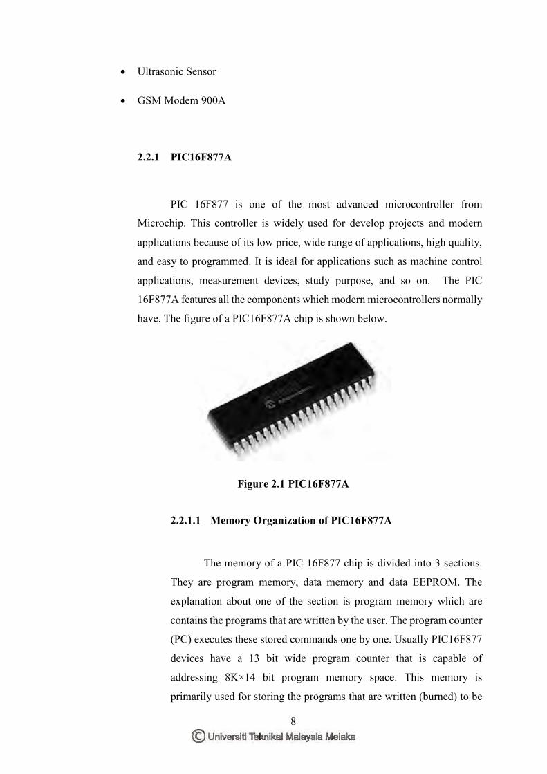
2.2.1 PIC16F877A
PIC 16F877 is one of the most advanced microcontroller from
Microchip. This controller is widely used for develop projects and modern
applications because of its low price, wide range of applications, high quality,
and easy to programmed. It is ideal for applications such as machine control
applications, measurement devices, study purpose, and so on. The PIC
16F877A features all the components which modern microcontrollers normally
have. The figure of a PIC16F877A chip is shown below.
Figure 2.1 PIC16F877A
2.2.1.1 Memory Organization of PIC16F877A
The memory of a PIC 16F877 chip is divided into 3 sections.
They are program memory, data memory and data EEPROM. The
explanation about one of the section is program memory which are
contains the programs that are written by the user. The program counter
(PC) executes these stored commands one by one. Usually PIC16F877
devices have a 13 bit wide program counter that is capable of
addressing 8K×14 bit program memory space. This memory is
primarily used for storing the programs that are written (burned) to be
9
used by the PIC. These devices also have 8K*14 bits of flash memory
that can be electrically erasable /reprogrammed. Each time when write
a new program to the controller, it must delete the old one at that time.
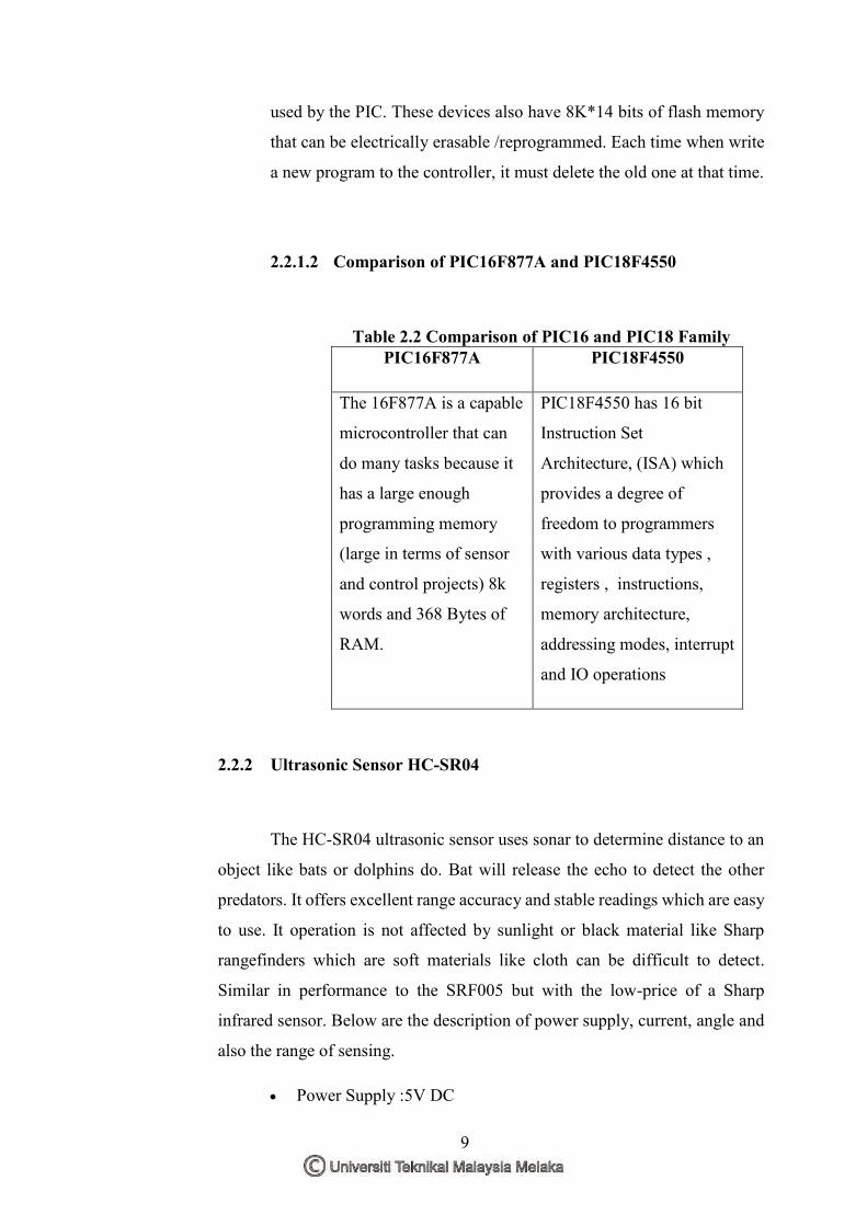
2.2.1.2 Comparison of PIC16F877A and PIC18F4550
Table 2.2 Comparison of PIC16 and PIC18 Family PIC16F877A PIC18F4550
The 16F877A is a capable
microcontroller that can
do many tasks because it
has a large enough
programming memory
(large in terms of sensor
and control projects) 8k
words and 368 Bytes of
RAM.
PIC18F4550 has 16 bit
Instruction Set
Architecture, (ISA) which
provides a degree of
freedom to programmers
with various data types ,
registers , instructions,
memory architecture,
addressing modes, interrupt
and IO operations
2.2.2 Ultrasonic Sensor HC-SR04
The HC-SR04 ultrasonic sensor uses sonar to determine distance to an
object like bats or dolphins do. Bat will release the echo to detect the other
predators. It offers excellent range accuracy and stable readings which are easy
to use. It operation is not affected by sunlight or black material like Sharp
rangefinders which are soft materials like cloth can be difficult to detect.
Similar in performance to the SRF005 but with the low-price of a Sharp
infrared sensor. Below are the description of power supply, current, angle and
also the range of sensing.
Power Supply :5V DC