Embed Size (px)
Citation preview

Comments, suggestions, or questions on this document should be addressed to: Commander, Naval Sea Systems Command, ATTN: SEA 05M2, 1333 Isaac Hull Avenue, SE, Stop 5160, Washington Navy Yard DC 20376-5160 or emailed to [email protected], with the subject line “Document Comment”. Since contact information can change, you may want to verify the currency of this address information using the ASSIST Online database at http://assist.daps.dla.mil.
AMSC N/A FSC 6105
INCH-POUND MIL-DTL-17060G(SH) 8 January 2009 SUPERSEDING MIL-M-17060F(SH) 25 May 1995
DETAIL SPECIFICATION
MOTORS, ALTERNATING CURRENT, INTEGRAL-HORSEPOWER, SHIPBOARD USE
This specification is approved for use by the Naval Sea Systems Command, Department of the Navy, and is available for use by all Departments and Agencies of the Department of Defense.
1. SCOPE
1.1 Scope. This specification covers the requirements for three-phase, alternating current (AC) motors for shipboard use in frame sizes not less than 182.
1.2 Classification. Motors furnished in accordance with this specification have the following services as specified (see 6.2):
a. Service A - Heavy-duty, high impact, shock-resistant motors for driven auxiliaries including propulsion which are essential to the military effectiveness of a ship.
b. Service C - Commercial marine motors for driven auxiliaries which are not essential to the military effectiveness of a ship.
2. APPLICABLE DOCUMENTS
2.1 General. The documents listed in this section are specified in sections 3, 4, and 5 of this specification. This section does not include documents cited in other section of this specification or recommended for additional information or as examples. While every effort has been made to ensure the completeness of this list, document users are cautioned that they must meet all specified requirements of documents cited in sections 3, 4, or 5 of this specification, whether or not they are listed.
2.2 Government documents.
2.2.1 Specifications, standards, and handbooks. The following specifications, standards, and handbooks form a part of this document to the extent specified herein. Unless otherwise specified, the issues of these documents are those cited in the solicitation or contract.
FEDERAL SPECIFICATIONS
QQ-B-654 - Brazing Alloys, Silver
FEDERAL STANDARDS
FED-STD-H28 - Screw-Thread Standards for Federal Services
Downloaded from http://www.everyspec.com

MIL-DTL-17060G(SH)
2
COMMERCIAL ITEM DESCRIPTIONS
A-A-59581 - Bearing, Ball, Annular, Single Row, Radial, Non-Filling Slot, Bore Diameters under 10 mm
A-A-59582 - Bearing, Ball, Annular, Single Row, Radial, Non-Filling Slot, Dimension Series 19
A-A-59583 - Bearing, Ball, Annular, Single Row, Radial, Non-Filling Slot, Dimension Series 10
A-A-59584 - Bearing, Ball, Annular, Single Row, Radial, Non-Filling Slot, Dimension Series 02
A-A-59585 - Bearing, Ball, Annular, Single Row, Radial, Non-Filling Slot, Dimension Series 03
A-A-59586 - Bearing, Ball, Annular, Single Row, Radial, Non-Filling Slot, Dimension Series 04
A-A-59587 - Bearing, Ball, Annular, Single Row, Radial, Filling Slot, Dimension Series 02
A-A-59589 - Bearing, Ball, Annular, Single Row, Radial, Filling Slot, Dimension Series 03
A-A-59595 - Bearing, Ball, Annular, Single Row, Radial, Non-Filling Slot, Cartridge Type Without Grease Plug, Dimension Series 32
A-A-59596 - Bearing, Ball, Annular, Single Row, Radial, Non-Filling Slot, Cartridge Type Without Grease Plug, Dimension Series 33
A-A-59597 - Bearing, Ball, Annular, Double Row, Radial, Internal Self-Aligning, Dimension Series 02
A-A-59598 - Bearing, Ball, Annular, Double Row, Radial, Internal Self-Aligning, Dimension Series 03
A-A-59599 - Bearing, Ball, Annular, Double Row, Radial, Internal Self-Aligning, Dimension Series 22
A-A-59600 - Bearing, Ball, Annular, Double Row, Radial, Internal Self-Aligning, Dimension Series 23
A-A-59623 - Bearing, Ball, Annular, Single Row, Angular Contact, Contact Angle 11 through 22, Dimension Series 19
A-A-59624 - Bearing, Ball, Annular, Single Row, Angular Contact, Contact Angle 11 through 22, Dimension Series 10
A-A-59625 - Bearing, Ball, Annular, Single Row, Angular Contact, Contact Angle 11 through 22, Dimension Series 02
A-A-59626 - Bearing, Ball, Annular, Single Row, Angular Contact, Contact Angle 11 through 22, Dimension Series 03
A-A-59627 - Bearing, Ball, Annular, Single Row, Angular Contact, Contact Angle 11° through 22°, Dimension Series 04
A-A-59628 - Bearing, Ball, Annular, Single Row, Angular Contact, Contact Angle 23° through 32°, Dimension Series 10
A-A-59629 - Bearing, Ball, Annular, Single Row, Angular Contact, Contact Angle 23° through 32°, Dimension Series 02
Downloaded from http://www.everyspec.com

MIL-DTL-17060G(SH)
3
A-A-59630 - Bearing, Ball, Annular, Single Row, Angular Contact, Contact Angle 23° through 32°, Dimension Series 03
A-A-59631 - Bearing, Ball, Annular, Single Row, Angular Contact, Contact Angle 23° through 32°, Dimension Series 04
A-A-59632 - Bearing, Ball, Annular, Single Row, Angular Contact, Contact Angle 33° through 45°, Dimension Series 10
A-A-59633 - Bearing, Ball, Annular, Single Row, Angular Contact, Contact Angle 33° through 45°, Dimension Series 02
A-A-59634 - Bearing, Ball, Annular, Single Row, Angular Contact, Contact Angle 33° through 45°, Dimension Series 03
A-A-59635 - Bearing, Ball, Annular, Single Row, Angular Contact, Contact Angle 33° through 45°, Dimension Series 04
A-A-59636 - Bearing, Ball, Annular, Double Row, Angular Contact, Non-Filling Contact, Vertex of Contact Angles Outside Bearing Dimension Series 32
A-A-59637 - Bearing, Ball, Annular, Double Row, Angular Contact, Non-Filling Slot, Vertex of Contact Angles Outside Bearing, Dimension Series 33
A-A-59638 - Bearing, Ball, Annular, Double Row, Angular Contact, Non-Filling Slot, Vertex of Contact Angles Inside Bearing, Dimension Series 32
A-A-59639 - Bearing, Ball, Annular, Double Row, Angular Contact, Filling slot, Vertex of Contact Angles Inside Bearing, Dimension Series 33
A-A-59640 - Bearing, Ball, Annular, Double Row, Angular Contact, Filing Slot, Vertex of Contact Angles Outside Bearing, Dimension Series 32
A-A-59641 - Bearings, Ball, Annular, Double Row, Angular Contact, Filling Slot, Vertex of Contact Angles Outside Bearing, Dimension Series 33
A-A-59685 - Grease, Sealed Ball and Roller Bearing
A-A-59720 - Sealing and Locking Compounds, Single-Component
DEPARTMENT OF DEFENSE SPECIFICATIONS
MIL-S-901 - Shock Tests, H.I. (High-Impact) Shipboard Machinery, Equipment, and Systems, Requirements for
MIL-E-917 - Electric Power Equipment, Basic Requirements (Naval Shipboard Use)
MIL-DTL-1222 - Studs, Bolts, Screws, and Nuts for Applications Where a High Degree of Reliability is Required; General Specification for
MIL-E-2036 - Enclosures for Electric and Electronic Equipment, Naval Shipboard
MIL-DTL-15024 - Plates, Tags, and Bands for Identification of Equipment, General Specification for
MIL-P-15024/5 - Plate, Identification
MIL-E-16298 - Electric Machines Having Rotating Parts, Accessories and Associated Support Items: Packaging of
MIL-T-16366 - Terminals, Electric Lug and Conductor Splices, Crimp-Style
Downloaded from http://www.everyspec.com

MIL-DTL-17060G(SH)
4
MIL-PRF-17331 - Lubricating Oil, Steam Turbine and Gear, Moderate Service
MIL-B-17931 - Bearings, Ball, Annular, for Quiet Operation
MIL-DTL-18240 - Fastener Element, Self-Locking, Threaded Fastener, 250 °F Maximum
MIL-L-19140 - Lumber and Plywood, Fire-Retardant Treated
MIL-R-21248 - Rings, Retaining (Tapered and Reduced Section Type)
MIL-I-24092 - Insulating Varnishes and Solventless Resins for Application by the Dip Process
MIL-I-24178 - Insulation Tape, Electrical, Semi-Cured Thermosetting Resin Treated Glass, Armature Banding, Naval Shipboard
DOD-G-24508 - Grease, High Performance, Multi-Purpose (Metric)
MIL-C-24707 - Castings, Ferrous, General Specification for
MIL-C-24707/l - Castings, Ferrous, for Machinery and Structural Applications
MIL-C-24707/5 - Castings, Ductile Iron and Austenitic Ductile Iron
MIL-M-24738 - Monitors, High Temperature Motor Protection
DEPARTMENT OF DEFENSE STANDARDS
MIL-STD-108 - Definitions of and Basic Requirements for Enclosures for Electric and Electronic Equipment
MIL-STD-461 - Requirements for the Control of Electromagnetic Interference Characteristics of Subsystems and Equipment
MIL-STD-740-1 - Airborne Sound Measurements and Acceptance Criteria of Shipboard Equipment
MIL-STD-740-2 - Structureborne Vibratory Acceleration Measurements and Acceptance Criteria of Shipboard Equipment
MIL-STD-2037 - Procedure to Obtain Certification for Electric Motor Sealed Insulation Systems
(Copies of these documents are available online at http://assist.daps.dla.mil/quicksearch/ or from the Standardization Document Order Desk, 700 Robbins Avenue, Building 4D, Philadelphia, PA 19111-5094.)
2.3 Non-Government publications. The following documents form a part of this document to the extent specified herein. Unless otherwise specified, the issues of the documents are those cited in the solicitation or contract.
AMERICAN BEARING MANUFACTURERS ASSOCIATION (ABMA)
ABMA 9 - Load Ratings and Fatigue Life for Ball Bearings
ABMA 20 - Radial Bearings of Ball, Cylindrical Roller and Spherical Roller Types, Metric Design
(Copies of these documents are available from the American Bearing Manufacturers Association, 2025 M. Street, NW, Suite 800, Washington DC 20036 or online at www.abma-dc.org.)
Downloaded from http://www.everyspec.com

MIL-DTL-17060G(SH)
5
AMERICAN WELDING SOCIETY (AWS)
AWS A5.8 - Specification for Filler Metals for Brazing and Braze Welding (DoD adopted)
(Copies of this document are available from the American Welding Society, 550 N.W. LeJeune Road, Miami, FL 33126 or online at www.aws.org.)
ASTM INTERNATIONAL
ASTM A47/A47M - Standard Specification for Ferritic Malleable Iron Castings (DoD adopted)
ASTM A153/A153M - Standard Specification for Zinc Coating (Hot-Dip) on Iron and Steel Hardware (DoD adopted)
ASTM A216/A216M - Steel, Castings, Carbon, Suitable for Fusion Welding, for High Temperature Service (DoD adopted)
ASTM A29/A29M - Standard Specification for Steel Bars, Carbon and Alloy, Hot-Wrought, General Requirements for
ASTM A489 - Standard Specification for Carbon Steel Lifting Eyes (DoD adopted)
ASTM A677 - Standard Specification for Nonoriented Electrical Steel, Fully Processed Types
ASTM A683 - Standard Specification for Nonoriented Electrical Steel, Semiprocessed Types
ASTM A757/A757M - Standard Specification for Steel Castings, Ferritic and Martensitic, for Pressure-Containing and Other Applications, for Low-Temperature Service
ASTM B21/B21M - Standard Specification for Naval Brass Rod, Bar, and Shapes (DoD adopted)
ASTM B23 - Standard Specification for White Metal Bearing Alloys (Known Commercially as Babbitt Metal)
ASTM B26/B26M - Standard Specification for Aluminum-Alloy Sand Castings (DoD adopted)
ASTM B30 - Standard Specification for Copper-Base Alloys in Ingot Form
ASTM B505/B505M - Standard Specification for Copper-Base Alloy Continuous Castings
ASTM B633 - Standard Specification for Electrodeposited Coatings of Zinc on Iron and Steel (DoD adopted)
ASTM D4727/D4727M - Standard Specification for Corrugated and Solid Fiberboard Sheet Stock (Container Grade) and Cut Shapes
ASTM D5948 - Standard Specification for Molding Compounds, Thermosetting
(Copies of these documents are available from ASTM International, 100 Barr Harbor Dr., P.O. Box C700, West Conshohocken, PA 19428-2959 or online at www.astm.org.)
Downloaded from http://www.everyspec.com

MIL-DTL-17060G(SH)
6
INTERNATIONAL ELECTROTECHNICAL COMMISSION (IEC)
IEC 60034-18-41 - Qualification and Type Tests for Type 1 Electrical Insulation Systems Used in Rotating Electrical Machines Fed From Voltage Converters
IEC 61934 - Electrical Measurements of Partial Discharge (PD) During Short Rise Time and Repetitive Voltage Impulses
(Copies of these documents are available from the IEC, 3 rue de Varembé, P.O. Box 131, CH-1211 Geneva 20, Switzerland or online at www.iec.ch.)
NATIONAL ELECTRICAL MANUFACTURER’S ASSOCIATION (NEMA)
NEMA MW1000 - Magnet Wire
(Copies of this document are available from the National Electrical Manufacturers Association, 1300 North 17th Street, Suite 1847, Rosslyn, VA 22209 or online at www.nema.org.)
SAE INTERNATIONAL
SAE AMS2469 - Hard Anodic Coating on Aluminum and Aluminum Alloys
SAE AMS7259 - Packing, Preformed - O-Ring Seal
SAE AMS7276 - Packing, Preformed - O-Ring Seal
(Copies of these documents are available from SAE World Headquarters, 400 Commonwealth Drive, Warrendale, PA 15096-0001 or online at www.sae.org.)
2.4 Order of precedence. Unless otherwise noted herein or in the contract, in the event of a conflict between the text of this document and the references cited herein, the text of this document takes precedence. Nothing in this document, however, supersedes applicable laws and regulations unless a specific exemption has been obtained.
3. REQUIREMENTS
3.1 First article. When specified (see 6.2), a sample shall be subjected to first article inspection (see 6.4) in accordance with 4.2.
3.2 Reliability. Bearings shall be selected to provide a calculated B-10 life of not less than 10,000 hours. Bearing life shall be calculated in accordance with ABMA 9 for single bearings and, unless otherwise specified (see 6.2), in accordance with MIL-B-17931 for duplex bearings. Bearing life extension factors, identified in ABMA 9, shall not be used in bearing life calculations.
3.3 Materials, parts, and processes. Unless otherwise specified herein, materials, parts, and processes shall be in accordance with MIL-E-917.
3.3.1 Hazardous material. Materials and parts containing asbestos, cadmium, lithium, mercury, radioactive materials, or materials giving off toxic fumes under operation shall not be used.
3.3.2 Recycled, recovered, or environmentally preferable materials. Recycled, recovered, or environmentally preferable materials should be used to the maximum extent possible, provided that the material meets or exceeds the operational and maintenance requirements, and promotes economically advantageous life cycle costs.
3.3.3 Material compatibility. Materials which (through outgassing or other physical phenomena) cause deterioration of other materials or degradation of equipment performance shall not be used.
3.4 Safety. Unless otherwise specified herein, safety shall be in accordance with MIL-E-917. The equipment shall provide protection for personnel against accidental contact with moving parts and voltages in excess of 30 volts root mean square (Vrms) or 30 volts direct current (Vdc).
3.5 Design and construction requirements. Motors shall be in accordance with 3.5.1 and 3.5.2. 6.3 should also be considered.
Downloaded from http://www.everyspec.com

MIL-DTL-17060G(SH)
7
3.5.1 General. Service A and Service C motors shall meet the requirements of 3.5.1.1 through 3.5.1.38.
3.5.1.1 Voltage and frequency variation. Motors shall operate in accordance with the requirements of this specification at rated voltage and frequency. Motors shall perform satisfactorily when operated with a variation in voltage or frequency as follows:
a. ±10 percent of rated voltage, with rated frequency. b. ±5 percent of rated frequency, with rated voltage. c. A combined variation in voltage and frequency of 10 percent (sum of absolute values) of rated values,
provided the frequency variation does not exceed ±5 percent of rated frequency.
3.5.1.2 Rated voltage and frequency. Motors shall operate with the following rated voltages and frequencies, as specified (see 6.2):
a. Voltage: (1) 220 volts alternating current (Vac) (2) 440 Vac (3) 115 Vac (4) Special
b. Frequency: (1) 60 hertz (2) Special
3.5.1.3 Ambient temperature. Motors shall operate in accordance with this specification in the following ambient temperature as specified (see 6.2):
a. 104 degrees Fahrenheit (°F) [40 degrees Celsius (°C)] b. 122 °F (50 °C) c. 149 °F (65 °C) d. 158 °F (70 °C) e. 176 °F (80 °C) or more
3.5.1.4 Winding. Motors shall be wound by use of coils preformed or mush wound coils without recourse to special equipment beyond that normally available at field electric repair facilities. Motor windings shall have an integral number of turns per coil or shall be half-turn windings.
3.5.1.5 Air gap. Motors shall be constructed for a minimum air gap of not less than 0.0025 inch per inch of rotor outside diameter except a minimum air gap of 0.012 inch for rotor diameters 4.8 inches or less.
3.5.1.6 Duty and duty cycle. Duty of motors shall be continuous, intermittent, varying or short-time, as specified (see 6.2). Motors of other than continuous duty shall have a defined duty cycle (see 6.2).
3.5.1.7 Thermal protection. When specified (see 6.2), motors shall be provided with thermal protection (see 6.6.28) for the stator windings. A minimum of two thermal sensors per phase, located in the same pole-phase group, shall be imbedded in the stator winding. The pole-phase groups, with sensors, shall be equally spaced about the stator diameter. Sensor leads shall be flexible and shall be secured to the coilhead at a location near where they will exit the coilhead to prevent force from being transmitted to the sensor. For one sensor per phase, the lead length extending beyond the point where they are secured to the coilhead shall be coiled and tied to the coilhead. When specified (see 6.2), motors shall be provided with a minimum of one thermal sensor in contact with each bearing outer ring. Where the sensors used are thermistors, thermal protection shall be provided in accordance with MIL-M-24738. Thermal sensors shall be monitored with one sensing network (monitor) that shall energize an alarm or de-energize the motor control within ±41 °F (5 °C) of the set point of the thermal sensor.
Downloaded from http://www.everyspec.com

MIL-DTL-17060G(SH)
8
3.5.1.8 Enclosures. Enclosures shall be in accordance with Class 2 of MIL-E-2036. For submarine applications, see 3.5.2.5.1. For degrees of enclosure greater than totally enclosed, except for explosionproof, also see 3.5.1.19. Air-over (AO) (see 6.6.7.1) enclosures such as TEAO, SPTAO, and EXPAO shall meet the requirements of MIL-E-2036 for enclosures TE, SPT, and EXP, respectively. Unless otherwise indicated in the duty cycle (see 3.5.1.6), submersible motors (see 6.6.7.2) shall operate continuously in air. Submersible motors that operate continuously in air may have a frame size in accordance with the provisions for totally enclosed (TE) motors (see figures 1 through 4). Enclosures shall be one of the following types as specified (see 6.2 and 6.6.7):
Dripproof protected - DPP Spraytight - SPT 1/ Spraytight fan-cooled - SPTFC 1/ Spraytight air-over - SPTAO 1/ Watertight - WT 2/ Totally enclosed air-over - TEAO Totally enclosed - TE Totally enclosed fan cooled - TEFC Explosionproof air-over, group D - EXPAO Explosionproof, group D - EXP Explosionproof, fan cooled, group D - EXPFC Submersible (3 ft) - SUB3 3/ Submersible (15 ft) - SUB15 3/ Submersible (50 ft) - SUB50 3/
NOTES: 1/ Shaft leakage shall be prevented without the use of shaft rubbing seals. Slingers shall be non-corrodible
and non-sparking. The fit between slinger and shaft shall prevent leakage along the shaft without fillers (see MIL-E-2036).
2/ The enclosure shall have as a minimum a single-faced, continuously lubricated, non-corrodible, shaft seal without shaft rubbing element.
3/ The enclosure shall have as a minimum a double-faced, continuously lubricated, non-corrodible, shaft seal without shaft rubbing element.
3.5.1.9 Speed. The rated speed in revolutions per minute (r/min) or rated speed range in r/min shall be as specified (see 6.2). The speed shall be constant (see 6.6.25.1), multi (see 6.6.25.2), adjustable (see 6.6.25.3), varying (see 6.6.25.4), or adjustable varying (see 6.6.25.5) as specified (see 6.6.4 through 6.6.25.5).
3.5.1.10 Standard horsepower (hp) ratings. Motors shall be furnished in the following standard hp ratings, as specified (see 6.2):
½ 2 10 30 75 200 400
¾ 3 15 40 100 250 450
1 5 20 50 125 300 500
1½ 7½ 25 60 150 350 and above
3.5.1.11 Design and types. Motors shall be of the following types and designs, as specified (see 6.2 and 6.6.26 through 6.6.27).
a. Squirrel-cage induction (see 6.6.26): (1) Design A (see 6.6.26.1)
Downloaded from http://www.everyspec.com
MIL-DTL-17060G(SH)
9
(2) Design B (see 6.6.26.2) (3) Design B7 (see 6.6.26.3) (4) Design C (see 6.6.26.4) (5) Design D (see 6.6.26.5) (6) Design F (see 6.6.26.6) (7) Design FF (see 6.6.26.7)
b. Synchronous (see 6.6.27): (1) Permanent magnet:
(a) Radial gap type (b) Axial gap type
3.5.1.12 Full-load power factor, designs A, B, and B7.
3.5.1.12.1 Single speed induction motors. The full-load power factor (see 6.6.18) for single speed induction motors shall be not less than 0.80 except for single speed induction motors 15 hp and less, or single speed induction motors with synchronous speeds of 900 r/min and less, which shall be not less than 0.70. Motors with synchronous speeds of 600 r/min and less need not conform to this requirement.
3.5.1.12.2 Multispeed induction motors. The full-load power factor for the high speed of a multispeed induction motor shall be not less than 0.05 below that of a motor of the single speed rating.
3.5.1.13 Structureborne noise. The following factors shall be considered by the contractor in the design of the motors to meet the requirements of 3.6.3.2:
a. Precision machining of rolling, rubbing, and fitting parts. b. Minimize imbalance incurred during the production phase to minimize corrections required during the final
balancing phase. c. Provisions for in-place balancing of rotating parts and access for in-place balancing. d. Sharp cutoffs and turbulence avoided in the air cooling system. Ventilation ducts and housings damped to
prevent flow-excited vibration. e. Number of slots per pole. f. Proximity of the slot frequency to the natural frequency of the magnetic frame. g. Skewing of stator or rotor slots. h. Magnetic core and tooth flux densities. i. Frequency and amplitude of structureborne noise to accommodate noise limits specified for the auxiliary
and motor assembly.
3.5.1.14 Mechanical fasteners. Mechanical fasteners shall be in accordance with MIL-E-917. Thread engagement for mechanical fasteners, where mating materials are similar or dissimilar, shall be in accordance with FED-STD-H28 (see MIL-E-917).
3.5.1.15 Mechanical balance. The rotating assemblies of motors shall be mechanically balanced at all loads and speeds in the operating range to meet the required levels of balance and structureborne noise. Mechanical balance correction shall be effected by the following methods:
a. Balance ring(s) shall be provided when super-precision levels of balance are specified and shall be in accordance with MIL-E-917 and the following. Balance rings shall be located outboard of the bearings and shall provide a fine adjustment for balance correction. Other balancing methods, as described in subparagraph (b) below, shall be used to obtain the majority of the balance correction.
b. The following methods of balance correction are listed in their order of preference: (1) Weight removal. (2) Weight addition - weights shall be securely attached to the rotating assembly.
Downloaded from http://www.everyspec.com

MIL-DTL-17060G(SH)
10
(a) Bolts and washers shall be corrosion resistant. Bolts shall be securely attached when a corrosion resistant, split-ring lockwasher and one of the following methods of attachment are used:
1 Bolts or nuts with nylon inserts in accordance with MIL-DTL-18240, Type P or N, if temperature conditions permit.
2 Thread locking compound in accordance with A-A-59720. 3 Welding of bolt head to steel plate. Bolts shall not be directly welded to rotor laminations.
The split-ring lockwasher shall be substituted for by one of the locking methods indicated above. (b) When correcting imbalance with bolts and washers, the stack height of washers placed under a
bolt head, including the lockwasher, shall be limited to that which shall provide no less than the minimum thread engagement between the bolt and the threaded hole in accordance with FED-STD-H28 (see MIL-E-917).
(c) Steel weights, securely welded. Weights shall not be welded directly to rotor laminations. c. For wound rotating assemblies, the use of solder on banding wire is permissible subject to the following
limitations: (1) Diameter of the rotor does not exceed 16 inches. (2) Peripheral speed does not exceed 6,500 feet per minute at synchronous speed. (3) Armature cores are balanced before the windings are inserted. (4) Only tinned banding wire is used. (5) The solder does not cover an arc of more than 25 percent of the circumference of the armature
measured on the banding wire unless satisfactory to the Command or agency concerned (where the manufacturer prebalances the armature and takes care in placing the windings in the slots to reduce unbalance due to the axial misalignment of the coils, this value may be increased to 33 percent if satisfactory to the Command or agency concerned).
(6) Thickness of solder over banding wire does not exceed 3/32 inch, and in no case extends past the center of the air gap.
3.5.1.16 Armature and coil banding using glass. Semi-cured thermosetting resin treated glass insulation tape may be used for armature and coil banding in lieu of steel wire banding. Glass banding materials and methods of application shall be in accordance with MIL-I-24178.
3.5.1.17 Field coils. Field coils for synchronous motors shall be thoroughly insulated from adjacent, conducting, and grounded parts. They shall be secured to prevent motion of the coil with respect to the poles or other parts when the motor is operating. Coils of the same type shall be interchangeable.
3.5.1.18 Mounting. Motors shall be configured for mounting either in the horizontal or vertical position as specified (see 6.2). Mounting feet or flanges, as specified (see 6.2), shall have machined mounting surfaces and shall be provided with round holes for mounting bolts (for submarine application see 3.5.2.5.2 and 3.5.2.5.3).
3.5.1.19 End shields (EXP, EXPFC, and EXPAO motors excluded). An accurate shoulder joint shall be provided between the frame and end shields. When specified (see 6.2), the end shields shall provide for the rotation through 90 degrees or 180 degrees in either direction to allow for bulkhead or underside suspension of the motor. Resilient gaskets shall not be placed between any bearing support member or bearing end cap and the frame or end shield. For spraytight, watertight, and submersible motors, the contact surfaces between the enclosing covers (ex. outer bearing caps) and the motor frame or end shields and between the frame and end shields shall be free from fins, burrs, or other imperfections detrimental to watertightness. The contact surfaces shall provide the necessary degree of watertightness by creating a tight metal-to-metal fit or shall be provided with O-rings suitably retained and treated with graphite on the contact surface to prevent sticking. The use of sealants to create watertightness is prohibited.
Downloaded from http://www.everyspec.com

MIL-DTL-17060G(SH)
11
3.5.1.20 Frames and covers. The finished motor frame shall be one piece. Loose spacers or any form of frame extension not welded or permanently attached to the frame or end shield shall not be used to extend the length of the frame. End shields shall be secured to the frame with not less than four hexagonal head or socket-head screws or bolts. Motor construction shall be based on the use of bolts or screws of tensile strength not greater than that for Grade 5 in accordance with MIL-DTL-1222. Through bolts may be used to secure the end brackets to the frame of motors built in a frame size 215 or smaller, except for explosion proof enclosures. Bolts shall be fitted with lockwashers in accordance with MIL-E-917. Enclosing covers (hand-hole or access-hole covers) shall be readily removable. Engaging bolts or locking devices shall be attached to the frame, end shield, or covers as the construction permits in such manner as to prevent the bolts or locking devices from being misplaced or dropped into the machine during repair operations. Motors shall be provided with a means to permit easy removal of end shields by any of the following methods (for submarine applications see 3.5.2.5.7 through 3.5.2.5.9):
a. Knock-off lugs integral with end bracket b. Holes drilled and tapped in end shield for use of jacking bolts c. Recess in frame to permit contact of drift with end shield flange
3.5.1.20.1 Vertical fan-cooled motor covers. Vertical fan-cooled motors shall be furnished with a solid cover over the fan assembly to prevent personnel injury and to prevent foreign particles from falling into the fan.
3.5.1.20.2 Aluminum frames and end shields. Except for non-magnetic applications, aluminum alloys shall not be used for motor frames or end shields. Where used, aluminum shall be hard anodized in accordance with MIL-A-8625, Type 3, Class I or II, or SAE AMS2469. End shields shall not support the total weight of the motor driven auxiliary. Steel inserts shall be provided for all threaded positions and bearing housings.
3.5.1.21 Shafts. Unless otherwise specified (see 6.2), a shaft extension with keyway shall be provided and shall be in accordance with figures 1, 2, 3, and 4, as applicable (for submarine applications see 3.5.2.5.6).
3.5.1.22 Bearings. For additional bearing requirements refer to 3.5.2, as applicable.
3.5.1.22.1 Types of bearings. Unless otherwise specified (see 6.2), bearings shall be the ball type.
3.5.1.22.2 Ball bearing lubrication. Except as determined in accordance with 3.5.2.1.5.1, ball bearings shall be grease lubricated.
3.5.1.22.2.1 Lubrication and preservation. Except for motors using double seal or cartridge bearings, the following shall occur prior to the motor leaving the plant of manufacture:
a. The correct amount of clean grease shall be added to the grease reservoirs. b. The piping and grease passages leading to the grease reservoirs shall be filled with clean grease. c. A thin coat of clean grease shall be applied to the surfaces of the grease reservoir.
Grease shall be in accordance with DOD-G-24508. Where oil is the lubricant, the bearings shall be treated with a preservative compatible with the operating oil.
3.5.1.22.2.2 Lubrication provisions. Except for motors with double seal or cartridge bearings, motors shall be relubricable and shall not require disassembly for relubrication. Grease cups, pipes, where applicable, and drains shall be used when grease is a means of lubrication and relubrication of bearings is required. The grease cup shall not be mounted on the motor and the threaded hole used to attach the grease cup shall be provided with a pipe plug or cap. Grease inlet and drain passages shall be of minimum length. For motors critical to ship’s mission (see 6.2), grease passages shall be cleanable without motor disassembly, other than removal of any grease pipes. Grease pipes shall be removable without motor disassembly. Grease pipes, where used, shall be left on the motor; the end outermost from the motor shall be fitted with a pipe plug. Pipe plugs shall be accessible without motor disassembly. The grease inlet shall be located on or above the horizontal centerline of the bearing housing for horizontal motors and at any location convenient to the grease chambers above the bearing for vertical motors. Grease outlets shall be located to afford maximum purging of grease during regreasing operation.
3.5.1.22.2.3 Grease lubricant seals. Except where double seal or cartridge bearings are used, the bearing housing shall provide for a close clearance, metallic, nonrubbing seal on both sides of the bearings to prevent the leakage of oil or grease along the shaft. This is in addition to bearing shields or slingers, if required.
Downloaded from http://www.everyspec.com

MIL-DTL-17060G(SH)
12
3.5.1.22.3 Housing construction. Bearing housing shall permit ready removal of the end shield without removing the bearings. Motors with frame size less than 286 shall have removable inner bearing caps. Motors with frame size 286 and larger shall have removable inner and outer bearing caps. Bearing caps shall be secured with fasteners in such a manner that the fasteners shall be removable without dismantling the motor. Motors with cartridge or double seal bearings need not have inner bearing caps.
3.5.1.22.3.1 Removal of bearing. Construction shall permit removal of the ball bearing by pulling on the inner ring of the bearing.
3.5.1.22.3.2 Bearing preload washer or springs. The use of bearing preload washers, springs, or both shall be permitted provided they are secured in the housing. The spring or washer shall be applied in such a manner as to provide for temperature differential compensation specified in 3.5.2.1.5.2.
3.5.1.22.4 Caution plate. Where cartridge or double seal bearings are used, a plate bearing the words “CAUTION: DO NOT LUBRICATE” shall be permanently attached to the motor. The plate shall meet the requirements of 3.5.1.33.
3.5.1.22.5 Sleeve bearings and oil lubricated ball bearings. When use of sleeve bearings is specified (see 6.2), motors having rotors weighing less than 200 pounds may use either split or solid bushing type sleeve bearings. Split cylindrical sleeve bearings shall be used for rotor weights in excess of 200 pounds. Sleeve bearing construction shall be such that unit loads do not exceed 150 pounds per square inch (lb/in2) and the length to diameter ratio does not exceed one. Sleeve bearings shall be either Babbitt faced, bronze backed, or solid bronze.
3.5.1.22.5.1 Lubrication of sleeve bearings and oil lubricated ball bearings. Sleeve bearings shall be lubricated by a self-contained gear, disc, viscous pump, or forced feed lubrication system as required. Lubricant for sleeve bearings and oil lubricated ball bearings shall be in accordance with MIL-PRF-17331.
3.5.1.22.5.2 Oil discs. The number of oil discs shall be such that no disc is required to distribute lubricant for an axial distance greater than 3 inches on either side.
3.5.1.22.5.3 Bearing housing. The housing shall provide for a close clearance metallic seal on both sides of the bearings to prevent the leakage of oil along the shaft under all conditions of pitch, roll, or shock. This is in addition to the deflection flanges or slingers required on the shaft. Provision shall be made to ensure against the suction of oil vapor into the motor. Provision shall also be made for observation of the disc scrapers or pumps. These openings shall be oiltight and have a cover secured by a positive lock and gasket. Surface area and oil sump volume shall be adequate to transfer the heat generated in the bearing. Forced water or air cooling may be used. Bearing seats shall be line bored to produce good bearing alignment. The bearing bore centerline shall deviate by not more than 20 percent of the bearing clearance.
3.5.1.22.5.4 Filling. An opening or standpipe for filling, preventing overfilling, and indicating the oil level shall be provided in the reservoir. It shall be fitted with an oiltight plug or cap to prevent the escape of oil due to the motion of the ship. Positive venting shall be provided to assure pressure equalization in the motor. The diameter of the filling opening shall be not less than ¼ inch for machines built in frames of motors corresponding to 3 hp, continuous rating of 1,800 r/min, and not less than ⅜ inch for larger machines.
3.5.1.22.5.5 Threads. Straight threads shall be used on all plugs and fittings.
3.5.1.22.5.6 End play (sleeve bearings only). To ensure floating of the shaft in horizontal sleeve bearing motors, there shall be at least 1⁄64 inch end play in either direction.
3.5.1.23 Rotor and stator core.
3.5.1.23.1 Securing core to shaft. Provisions shall be made to prevent rotation of the core on the shaft and axial displacement of the core along the shaft. Keys, knurling of the shaft, or keys in conjunction with press or shrink fits shall be provided to prevent rotation of the core around the shaft. Press or shrink fits without keys to secure the core on the shaft to prevent axial or rotational movement of the core shall be as approved (see 6.11). Tack welding in conjunction with these methods is permissible to prevent axial displacement of the core along the shaft.
Downloaded from http://www.everyspec.com

MIL-DTL-17060G(SH)
13
3.5.1.23.2 Securing stator core to frame. Means shall be provided to prevent rotation of the core in the frame and axial displacement of the core along the frame.
3.5.1.24 Terminal boxes and terminal box covers. Terminal boxes and covers shall be provided and securely bolted or welded to the frame. Use of pipe nipples where they are necessary or where motors are to be used in inaccessible locations shall be as approved (see 6.11). Terminal boxes shall be provided with conduit openings as specified (see table I; for submarine applications see 3.5.2.5.4). For multispeed motors with multiple independent windings, one conduit opening of the size indicated in table I shall be provided for each hp rating. For motors rated over 250 hp, the conduit openings shall be sized to suit the number and diameter of ship cables specified (see 6.2).
TABLE I. National pipe thread (NPT) assignments for motor terminal boxes – nylon tubes. 1/
Maximum full-load amps NPT Tube size hp
18 ¾ 2 1, 2, 3, 5, and 7½
25 1 3 10, 15, 10, 25, and 30
110 1½ 5 40, 50, 60, and 75
185 2 6 100 and 125
250 2½ 7 150
320 3 8 200
400 3½ 9 --
NOTE: 1/ NPT sizes are based on the maximum expected three-conductor cable size. If cable size permits,
the hole size may be reduced to the next lower size by use of a reducing bushing which will be inserted by the installing activity. If steel tubes are used, the installing activity shall provide the proper size reducing bushing to fit.
3.5.1.25 Connections and terminals.
3.5.1.25.1 Securing connections. Connections (mechanical and electrical) shall be provided with locking devices in accordance with MIL-E-917. Connections and leads shall be secured to prevent their coming in contact with moving parts or being chafed by contact with stationary parts. Excess solder shall be removed from soldered connections.
3.5.1.25.2 Field connections. In general and where practicable, field connections shall be made on the front end (see 6.6.8). In split-frame motors, the field connections which will be broken for disassembly shall be readily accessible.
3.5.1.25.3 Securing terminal leads. The leads shall be secured by a lead clamp or by anchoring them to the motor windings so that no strain is put on the end connections. Where a lead clamp is provided, it shall be attached to the frame and not to the end shields.
3.5.1.25.4 Cable connectors. The end of each motor lead shall be fitted with a connector for joining the motor lead to the supply circuit cable or wire. Ship service cables and their terminal lugs shall not be supplied by the motor manufacturer.
3.5.1.25.5 Flexible leads. Terminal leads shall be made of flexible, stranded insulated wire. Means to prevent abrasion of the lead insulation by metallic edges of the motor frame, terminal box, piping, or cable clamp shall be provided.
3.5.1.26 Lead wire identification. Lead wires shall be permanently marked in accordance with MIL-E-917.
Downloaded from http://www.everyspec.com

MIL-DTL-17060G(SH)
14
3.5.1.27 Painting. Painting shall be in accordance with MIL-E-917.
3.5.1.28 Lifting means. Means shall be provided for lifting motors weighing 150 pounds and over.
3.5.1.29 Temperature limitations. Motor temperature limitations shall be as specified in 3.6.11.
3.5.1.30 Conventional insulation. Conventional insulation, where applicable (see 3.5.2.1 and 3.5.2.2), shall be in accordance with MIL-E-917.
3.5.1.30.1 Insulation class. Insulation class shall be F, H, or N in accordance with MIL-E-917 (see 6.2). Where ambient temperatures of 104 °F or 122 °F (40 °C or 50 °C) are specified, the insulation shall be Class F.
3.5.1.30.2 Slot insulation and varnishing. Slot cell shall be folded under the slot wedge if flat wedge is used, or inserted inside the slot wedge if formed (curved) wedge is used. The wedge shall extend the full length of the slot and extend past the iron a minimum of ¼ inch. The wedge shall be positioned so as to completely cover the slot cell. For motors in frame sizes 215 or smaller, the flat or curved wedges may be inserted inside the slot cell, and in such cases, the following conditions shall apply:
a. The slot wedge shall extend the full length of the slot cell and completely cover the windings and close the slot necks.
b. The wound stator shall be given a minimum of two varnish dips and bakes.
3.5.1.31 Sealed insulation system. The sealed insulation system (see 6.6.24) shall be applied to random wound and form wound motors by manufacturers qualified by NAVSEA in accordance with MIL-STD-2037 (see 4.2.1). For applicability of sealed insulation to particular motor services, see 3.5.2.1 and 3.5.2.2. In addition, motors with sealed insulation systems shall meet the following requirements:
a. Insulation shall be Class F. The insulating materials used in motors with a sealed insulation system need not meet the minimum material requirements of 3.5.2.1.1.
b. The terminal box shall be watertight. c. Motors furnished with sealed insulation systems shall be constructed so that they can be repaired (rewound)
using sealed insulating materials and processes or rewound using conventional rewinding materials and methods. d. Insulation resistance, corrected to 77 °F (25 °C), shall be not less than 1000 megohms, dry, and 100
megohms, submerged (see 4.6.19).
3.5.1.33 Identification. Motors shall have identification plates (and information plates where required) which shall be attached to the part of the machinery or equipment which will not ordinarily be replaced during its normal service life. These plates shall be located where they can be read at all times without danger to personnel. Identification plates and information plates shall be made of brass, nickel-copper-alloy, or corrosion-resistant steel in accordance with MIL-DTL-15024 and MIL-P-15024/5.
3.5.1.33.1 Identification plate markings. Unless otherwise specified (see 6.2), the minimum information to be on identification plates for motors shall include the following items:
a. Manufacturer’s information as follows: (1) Name (2) Identification symbols (3) Serial number (4) Manufacturer’s drawing number, including revision symbol (5) Date of manufacture
b. Salient design characteristics (this information shall agree with information shown in the classification block of manufacturer’s drawing):
(1) hp (or torque rating) (2) Design (3) Voltage
Downloaded from http://www.everyspec.com

MIL-DTL-17060G(SH)
15
(4) Measured full-load current (5) Type of motor (6) Full-load speed (7) Number of phases (8) Frequency (9) Ambient temperature
c. Where motors rated for intermittent duty, short-time, or varying duty are capable of operating continuously at some decreased rating, that continuous rating shall also be shown on the identification plate. If there is no continuous rating, it shall be so stated.
d. Class of insulation e. Frame size f. Enclosure type g. Efficiency (minimum) (see 6.6.5) h. Navy service i. Contract or order number
3.5.1.33.2 Frame and rotor. The manufacturer’s serial number shall be stamped or otherwise permanently marked in the solid metal of the frame underneath (covered by) the main identification plate. The part number, or other information sufficient to completely identify one rotor, shall be stamped or otherwise permanently marked on the shaft or rotor core. Marking of armatures and field coils shall identify the manufacturer and the style and type of motor.
3.5.1.33.3 Sealed insulation system information plates. Motors with sealed insulation shall have the following information plates:
a. The plate shall list the name of the activity performing the sealed insulation system. The plate shall also contain the statement: “Stator windings insulated to provide a sealed insulation system. Caution: When stripping, oven temperature not to exceed 370 °C, measured on core” (see figure 5).
3.5.1.34 Interchangeability. Bearing caps, bearing cap fasteners, end bells, end bell fasteners, air baffles, parts that affect lubrication, and repair parts that are physically interchangeable shall be either functionally interchangeable or shall be permanently marked “DE” (drive end) or “ODE” (opposite drive end) (see 6.6.1), as appropriate. Permanent marking shall be clearly legible and shall be accomplished by metal stamping or a process that will produce not less than an equivalent level of clarity and permanence. The above parts that are physically reversible shall be functionally reversible.
3.5.1.35 Direction of rotation. Unless otherwise specified (see 6.2), motors shall be inherently reversible (constructed for operation in either direction). Inherently nonreversible motors and motors driving nonreversible auxiliaries shall be equipped with permanently mounted identification plates as specified (see 3.5.1.33) to indicate the direction of rotation when viewed from the end of the motor opposite the normal drive shaft (see figure 5).
3.5.1.36 Provision for measuring speed (explosionproof and explosionproof, fan-cooled motors excluded). In motors having a single shaft extension, provision shall be made for the measurement of speed with a hand type tachometer. This shall be accomplished on the opposite drive end either by extending the shaft flush with (or slightly beyond) the outer face of the bearing housing, or by providing a hole and a plug in the outer end of the bearing housing. When a hole and plug are provided, the hole shall be threaded and not smaller than 9⁄16-inch diameter, and the plug shall not be able to interfere with the end of the shaft. A lathe center or other suitable hole shall be provided in the end of the shaft for the insertion of the tachometer tip. For fan-cooled motors a hole not smaller than 9⁄16-inch diameter shall be provided in the fan guard for access to the end of the shaft. The hole shall be securely covered and shall be in accordance with MIL-STD-108.
Downloaded from http://www.everyspec.com

MIL-DTL-17060G(SH)
16
3.5.1.37 Standardization. Squirrel-cage induction motors and radial gap synchronous motors shall be in accordance with the standardization requirements shown on figures 1 through 4. Applicable motor standardization requirements, contained in auxiliary equipment specifications, take precedence over figures 1 through 4. For submarine service, low noise applications on surface ships, or applications where the use of standard motors is not practical, nonstandard motors may be proposed for acceptance to the contracting activity. Nonstandard motors shall be as specified on figures 1 through 4, with the exception that the requirements of table A of figures 1 through 4 may be used as a guide.
3.5.1.38 Motors with cooling other than air. When motors with cooling other than air are specified (see 6.2), NAVSEA approval shall be provided (see 6.11).
3.5.2 Requirements applicable to individual services.
3.5.2.1 Service A motors. In addition to 3.5.2.1, Service A motors shall meet the requirements of 3.5.1 and 3.6. Service A motors shall also meet MIL-E-917 and the requirements of MIL-S-901 for Grade A shock. Service A motors shall be furnished with a sealed insulation system. Service A motors shall be brushless.
3.5.2.1.1 Materials. The minimum material requirements for Service A motors shall be as specified in table II except nonmagnetic materials for nonmagnetic motors shall be as specified in 3.5.2.4.2.
TABLE II. Minimum material requirements for service A motors.
Item Limitation Material Specifications or remarks Motor All sizes Materials containing
silicone shall not be used except in brushless motors
Balance rings All sizes Brass Bronze
Corrosion resistant steel Other inherently noncorrodible
material
ASTM B21/B21M ASTM B30 or
ASTM B505/B505M
Ball bearings General purpose – surface ship
A-A-59581 A-A-59582 A-A-59583 A-A-59584 A-A-59585 A-A-59586 A-A-59587 A-A-59589 A-A-59595 A-A-59596 A-A-59597 A-A-59598 A-A-59599 A-A-59600 A-A-59623 A-A-59624
A-A-59625A-A-59626A-A-59627A-A-59628A-A-59629A-A-59630A-A-59631A-A-59632A-A-59633A-A-59634A-A-59635A-A-59636A-A-59637A-A-59638A-A-59639A-A-59640A-A-59641
Ball bearings (continued) Noise quiet submarine
MIL-B-17931
Downloaded from http://www.everyspec.com

MIL-DTL-17060G(SH)
17
TABLE II. Minimum material requirements for service A motors - Continued.
Item Limitation Material Specifications or remarks Ball bearing caps All sizes Steel 1/
Malleable iron Nodular graphitic iron 3/
Aluminum
-------- ASTM A47/A47M
MIL-C-24707/5 Commercial treated for
corrosion resistance End shields All sizes Steel 1/
Malleable iron Nodular graphitic iron 3/
-------- ASTM A47/A47M
MIL-C-24707/5 Eyebolts, lifting Where used Steel ASTM A489, Zinc coated
per ASTM A153/A153M or ASTM B633, thickness
Class Fe/Zn 12, with a Type II finish
Fans – external
and internal
All sizes -------- --------
Steel 1/ Aluminum
Malleable iron Nodular graphitic iron 3/
ASTM B26/B26M
ASTM A47/A47M MIL-C-24707/5
Fans – external External fan for fan-cooled motors
Plastic, molded thermosetting ASTM D5948
Flanges – armature rotor Where used Steel 1/ -------- Frames All sizes
-------- --------
Steel 1/ Malleable iron
Nodular graphitic iron 3/
-------- ASTM A47/A47M
MIL-C-24707/5 Grease cups and pipes All sizes Steel 1/ Treated for corrosion
Relubricable bearings
DOD-G-24508
Grease, surface ship
Cartridge and double seal
A-A-59685
Grease, submarine
DOD-G-24508
Hand-hole or access covers
All sizes --------
Transparent plastic MIL-E-917
Insulation – ground and phase, lead and
connection, collector ring, spacers and separators,
washers, bushings, tubes, wedges and lead clamp
Class F, H, or N All types and classes MIL-E-917 and sealed insulation system
Lead wire Class F, H, or N All types and classes MIL-E-917 O-rings All sizes Fluorocarbon rubber AMS 7259 and AMS 7276
Oil, lubricating Maximum oil sump temperature
179.6 °F (82 °C)
MIL-PRF-17331 Navy symbol 2190TEP
Oil, discs All sizes Steel 1/ --------
Downloaded from http://www.everyspec.com

MIL-DTL-17060G(SH)
18
TABLE II. Minimum material requirements for service A motors - Continued.
Item Limitation Material Specifications or remarks Malleable iron ASTM A47/A47M
Aluminum ASTM B26/B26M
Part covers for totally enclosed type machines where the cover acts as a shield only, and not as a support for another part
such as auxiliary or brake
--------
Plastic molded thermosetting ASTM D5948
Quills and spiders Where used Steel 1/ -------- Scraper All sizes Brass Commercial Shafts Close-coupled
pumps All other motors
Steel Corrosion-resistant material
Tensile strength not less than 75,000 lb/in2 and
elongation not less than 18% in 2 inches
Shaft seals All sizes Brass Bronze
Corrosion resistant steel
Other inherently noncorrodible material
ASTM B21/B21M ASTM B30, ASTM
B505/B505M ASTM A29/29M
Sleeve bearings All sizes Bronze
Babbitt antifriction metal
ASTM B30 or ASTM B505/ B505M
ASTM B23, Alloy Number 2
Terminal boxes terminal box covers
All sizes Steel 1/ Malleable iron
Nodular graphitic-3 iron
ASTM A47/A47M MIL-C-24707/5
Wire, magnetic Types M2, K2, H2 Copper, round 2/ NEMA MW1000 Varnish insulating All classes MIL-I-24092
Wire, end turn banding All sizes Steel and non-magnetic alloy Commercial Wedges All sizes Steel
Brass Thermoset fiberglass
Nodular graphitic-3 iron
Commercial Commercial Commercial
MIL-C-24707/5 NOTES:
1/ Steel parts shall be cast, fabricated, wrought, or forged. Cast steel shall be in accordance with MIL-C-24707 and MIL-C-24707/1, Grades A1Q of ASTM A757/A757M or WCA of ASTM A216/A216M. For Grade WCA of ASTM A216/A216M, the Charpy impact test conditions shall be 20 foot-pounds and minus 20 °F.
2/ Alternate wire sizes - sizes other than those in NEMA MW1000 may be used provided the motor design is such as to permit rewinding with a size and shape wire specified in NEMA MW1000, having an equivalent or higher temperature rating.
3/ Modular graphitic iron shall be furnished in either of the following two grades: 1) 60-45-15, 2) 60-40-18.
3.5.2.1.2 Solder for winding connections. Solder, where required for electrical connections, shall be silver-base brazing alloy or copper-base brazing alloy in accordance with QQ-B-654 or AWS A5.8, respectively.
3.5.2.1.3 Windings.
Downloaded from http://www.everyspec.com

MIL-DTL-17060G(SH)
19
3.5.2.1.3.1 Coilhead dimension and forming. Forming fixtures shall not be used for the winding or rewinding of wound components to meet the winding end turn envelope dimensions.
3.5.2.1.3.2 Rotor windings. Coils shall be securely retained in the slot by wedges. Banding shall be by glass insulated tape (see 3.5.1.16) or by steel banding wire. Insulation used under the wire shall be in accordance with MIL-E-917.
3.5.2.1.4 Core material. Core material, laminations, shall be provided with C5 inorganic interlaminar insulation in accordance with ASTM A677 or ASTM A683 and shall withstand burn out temperatures of 701.6 °F (372 °C) for 16 hours.
3.5.2.1.5 Ball bearings. Bearings shall be selected in accordance with table II. Motor dimensions for bearing mounting shall be in accordance with table III. Additional bearing requirements are as follows:
a. Except for motors meeting the requirements of 3.5.2.1.5.3, bearings for surface ship motors shall be open, single shield, double shield, single seal, or cartridge type (see 3.5.1.22.4).
b. For bearings for submarine applications see 3.5.2.5.5. c. For surface ship noise quiet applications see 3.5.2.6.1. d. For 3600 r/min motors, grease lubricated bearings shall not exceed size 312. e. For 3600 r/min synchronous speed motors, bearings shall be loose (C3) internal fit as defined by ABMA 20
except for submarine applications or where axial end play is restricted. f. Other types proposed for special application requirements shall be as approved (see 6.11).
Downloaded from http://www.everyspec.com

MIL-DTL-17060G(SH)
20
TABLE III. Bearing shaft, shaft shoulder, housing, and housing shoulder diameters.
Shaft diameter Shaft
shoulder diameter
Housing diameter Housing shoulder diameter Bearing size
Minimum Maximum Minimum Minimum Maximum Maximum 203 0.6692 0.6695 0.770 1.5748 1.5754 1.339 204 0.7875 0.7878 0.940 1.8504 1.8510 1.614 205 0.9844 0.9847 1.140 2.0472 2.0479 1.811 206 1.1812 1.1815 1.340 2.4409 2.4416 2.205 207 1.3781 1.3785 1.530 2.8346 2.8353 2.598 208 1.5749 1.5753 1.730 3.1496 3.1503 2.913 209 1.7718 1.7722 1.930 3.3465 3.3474 3.110 210 1.9686 1.9690 2.130 3.5433 3.5442 3.276 211 2.1655 2.1660 2.410 3.9370 3.9379 3.580 212 2.3623 2.3628 2.717 4.3307 4.3316 3.976 213 2.5592 2.5597 2.913 4.7244 4.7253 4.370 214 2.7560 2.7565 3.110 4.9213 4.9233 4.567 215 2.9529 2.9534 3.307 5.1181 5.1191 4.764 216 3.1497 3.1502 3.622 5.5118 5.5128 5.039 217 3.3466 3.3472 3.819 5.9055 5.9065 5.433 218 3.5434 3.5440 4.016 6.2992 6.3002 5.827 219 3.7403 3.7409 4.213 6.6929 6.6939 6.221 220 3.9371 3.9377 4.409 7.0866 7.0876 6.614 221 4.1340 4.1346 4.685 7.4803 7.4815 7.008 222 4.3308 4.3314 4.875 7.8740 7.8752 7.402 303 0.6692 0.6695 0.906 1.8504 1.8510 1.614 304 0.7875 0.7878 1.024 2.0472 2.0479 1.811 305 0.9844 0.9847 1.140 2.4409 2.4416 2.280 306 1.1812 1.1815 1.340 2.8346 2.8353 2.620 307 1.3781 1.3785 1.590 3.1496 3.1503 2.940 308 1.5749 1.5753 1.813 3.5433 3.5442 3.310 309 1.7718 1.7722 2.000 3.9370 3.9379 3.560 310 1.9686 1.9690 2.270 4.3307 4.3316 4.000 311 2.1655 2.1660 2.468 4.7244 4.7253 4.380 312 2.3623 2.3628 2.688 5.1181 5.1191 4.750 313 2.5592 2.5597 2.968 5.5118 5.5128 5.190 314 2.7560 2.7565 3.156 5.9055 5.9065 5.560 315 3.9529 2.9534 3.380 6.2992 6.3002 5.940
Downloaded from http://www.everyspec.com

MIL-DTL-17060G(SH)
21
TABLE III. Bearing shaft, shaft shoulder, housing, and housing shoulder diameters - Continued.
Shaft diameter Shaft
shoulder diameter
Housing diameter Housing shoulder diameter Bearing size
Minimum Maximum Minimum Minimum Maximum Maximum
316 3.1497 3.1502 3.550 6.6929 6.6939 6.250 317 3.3466 3.3472 3.840 7.0866 7.0876 6.620 318 3.5434 3.5440 4.060 7.4803 7.4815 7.000 319 3.7403 3.7409 4.290 7.8740 7.8752 7.380 320 3.9371 3.9377 4.488 8.4646 8.4658 7.940 321 4.1340 4.1346 4.685 8.8583 8.8595 8.307 322 4.3308 4.3314 4.875 9.4488 9.4500 8.898 324 4.7245 4.7251 5.276 10.2362 10.2374 9.685 326 5.1182 5.1189 5.827 11.0236 11.0248 10.315
3.5.2.1.5.1 Size and series. Unless otherwise specified (see 6.2), the bearings shall be of the size and series as
shown in table B of figures 1 through 4, as applicable. Bearings at opposite ends of the motor shall be a different size. Grease lubricated ball bearings shall be selected so as to not exceed the ndm value of 350,000, where n is rotating speed in r/min and dm is bearing mean diameter (see 6.6.2) in millimeters. If this ndm value is exceeded, oil lubrication shall be provided.
3.5.2.1.5.2 Bearing mounting. Bearings shall be fully mounted in the end shields, not in a cartridge. Each bearing shall be secured on the shaft by a locknut and a lockwasher or by a locknut utilizing a nylon lock. For frames 215 and smaller, a beveled snap ring, Type III, Class 2 of MIL-R-21248, is acceptable in place of the locknut. Mounting of bearings methods are as follows:
a. Fixed-free method. The fixed bearing shall be constrained axially in the housing by suitable housing and end cap shoulders. For gear motors, the fixed bearing shall be on the gear end. The free end bearing housing shall provide a clearance for thermally induced, axial shaft growth of not less than 0.020 inch for frames 182 through 326, 0.035 inch for frames 365 through 445 and 0.060 inch for frames 505 and larger.
b. Opposed shoulder method. The shaft end play shall compensate for any relative movement that may occur between the shaft and the housing due to temperature differential between these parts. The end play shall be not less than 0.020 inch for frames 182 through 326 and 0.030 inch for frames 365 and larger. The end play shall be not greater than 0.045 inch for all frames (see 4.6.7).
3.5.2.1.5.3 Sealed bearings for surface ship motors. Surface ship motors meeting the criteria of 3.5.2.1.5.3.1 shall be provided with sealed bearings as described in 3.5.2.1.5.3.2.
3.5.2.1.5.3.1 Criteria for use of sealed bearings:
a. Motor application is suitable for general purpose bearings per table II. b. Motor application shall not require a noise tested bearing per MIL-B-17931. c. Maximum bearing bore for 2-pole motors is 30 millimeters. d. Maximum bearing bore for 4-pole motors is 65 millimeters. e. Maximum bearing bore for 6-pole motors and slower is 90 millimeters. f. Both motor bearings shall meet 3.5.2.1.5.3.1 a and b and c, d or e.
3.5.2.1.5.3.2 Sealed bearing characteristics.
a. Double seal with rubbing seals, general purpose, in accordance with table II.
Downloaded from http://www.everyspec.com

MIL-DTL-17060G(SH)
22
b. Lubricated with grease in accordance with A-A-59685. c. Grease fill, where D is the bearing bore in millimeters and N is the maximum synchronous speed in
revolutions per minute. (1) For applications where DN ≥ 108000, grease fill shall be 33 percent (see 3.5.2.1.5.1). (2) For applications where DN < 108000, grease fill shall be 45 percent (see 3.5.2.1.5.1).
d. Radial internal clearance shall be C3 per ABMA 20. When a looser clearance is required, it shall be C5.
3.5.2.1.6 Sleeve bearings. The lubricating disc shall clear all obstructions. Oil shall be removed from the disc by means of a brass scraper. The disc shall be attached to and rotate with the shaft, and shall deliver oil from the sump to the upper portion of the bearing for lubrication.
3.5.2.1.6.1 Oil disc. The disc shall be of uniform cross-section with a channel on the inside diameter to contain the oil while rotating. A brass scraper shall be mounted that shall remove oil from the channel of the disc for bearing lubrication.
3.5.2.1.6.2 Clearances. Oil clearances shall be as specified in table IV.
TABLE IV. Oil clearances.
Basic diameter of journal (inches)
Maximum diametrical oil clearance including shaft and bearing tolerances
(inch) 1.000 0.004 2.000 0.005 3.000 0.007 4.000 0.009 5.000 0.010 6.000 0.012 7.000 0.014 8.000 0.016 9.000 0.018
10.000 0.020
3.5.2.1.7 Method of attaching fans to shaft. Where fans are not an integral part of the shaft, one of the following methods shall be used in attaching fans to the shaft:
a. A key, shaft shoulder, and a nut with keyed lock washer. b. A key, shaft shoulders, and rings or tubing. c. A long key secured in a closed-end key seat with locked set screw secured on the key. d. A Woodruff key with a locked set screw secured on the key. The set screw shall not produce unbalance. e. A split fan with clamping bolts and key.
3.5.2.1.8 Thread cutting screws. Thread cutting (self-tapping) screws shall not be used to secure any part of the motor.
3.5.2.1.9 Securing terminal leads. The method of securing terminal leads shall be such that stress from outside the motor is not transmitted to electrical connections inside the motor. Unclamped, friction rubber bushings shall not be used to secure terminal leads. Sealing compounds for anchoring leads shall not be used (see 3.5.1.25.3).
Downloaded from http://www.everyspec.com

MIL-DTL-17060G(SH)
23
3.5.2.1.10 Cable connectors. Connectors shall be of the solderless type in accordance with MIL-T-16366 (see 3.5.1.25.4).
3.5.2.1.11 Temporary air filters. When specified (see 6.2), motors shall operate when air intakes are covered by a filtering media (see 6.2) temporarily attached to the motor housing.
3.5.2.1.12 Dynamic balance. Unless otherwise specified (see 6.2), the degree of balance shall be precision balance as specified in table V.
TABLE V. Mechanical balance levels.
Maximum allowable total amplitude (peak to peak) Motor speed
(r/min) Standard balance (inch)
Precision balance (inch)
Super-precision balance(inch)
3000-4000 0.001 0.0005 0.0002 1500-2999 0.0015 0.00075 0.0003 1000-1499 0.002 0.001 0.0004
999 and below 0.003 0.0015 --------
3.5.2.2 Service C motors. Service C motors shall be marine type commercial motors. In addition to the general requirements of 3.5.1 through 3.5.1.38, Service C motors shall meet the requirements of 3.5.2.2.1 through 3.5.2.2.4, 3.6, and the requirements of MIL-S-901 for Grade B shock. When specified (see 6.2), Service C motors for operation in severe environmental service condition such as propulsion applications, exposure to occasional salt spray, splashing, salt laden atmosphere, or submergence shall be provided with a sealed insulation system.
3.5.2.2.1 Protection against corrosion. Service C motors shall be protected against corrosion in accordance with MIL-E-917.
3.5.2.2.2 Magnet wire. The magnet wire shall be round and of such size as to permit rewinding with round integral sized copper wire in accordance with NEMA MW1000.
3.5.2.2.3 Ball bearings. Ball bearings shall be replaceable with the types specified in 3.5.2.1.5. Grease lubricated ball bearings shall be selected so as to not exceed the ndm value of 350,000, where n is rotating speed in r/min and dm is bearing mean diameter in millimeters. If this ndm value is exceeded, oil lubrication shall be provided. The bearings shall be mounted such that the axial movement of the shaft shall be not more than 0.045 inch, including bearing end play (see 4.6.7).
3.5.2.2.4 Dynamic balance. Unless otherwise specified (see 6.2), the degree of balance shall be standard balance as specified in table V.
3.5.2.3 Pump motors. When specified (see 6.2), pump motors shall meet Service A (see 3.5.2.1) or Service C (see 3.5.2.2) requirements as applicable and shall be as follows:
a. For dripproof protected pump motors, when an air intake at the pump end of the motor is provided, the air flow direction shall be at right angles to the shaft.
b. Except for motors with submersible or watertight enclosures, pump motors shall have a slinger with guard on each motor shaft extension immediately outside the end shield to prevent entrance of water into the bearing housing. The slinger shall have an external diameter of not less than 1.5 times the shaft diameter and an axial clearance between the end shield and slinger not greater than 30 mils. The guard need not be furnished if the slinger end shield or the pump configuration will ensure that no injury to personnel may result and no entrance of water into the bearing housing can take place. Balancing rings may also serve the function of a slinger if so constructed.
c. The maximum value of full-load slip for 2-pole, centrifugal pump motors, 100 hp and above, shall not exceed 1.25 percent at the conclusion of continuous full-load heat run.
Downloaded from http://www.everyspec.com

MIL-DTL-17060G(SH)
24
3.5.2.4 Nonmagnetic motors. When specified (see 6.2), nonmagnetic motors shall meet the Service A requirements (see 3.5.2.1) and shall be as specified in 3.5.2.4.1 and 3.5.2.4.2.
3.5.2.4.1 Construction. Motors shall be as follows:
a. Have not less than four poles b. Have no protuberances of magnetic material, such as feet or supports
3.5.2.4.2 Materials. Materials shall be as follows:
a. Parts shall be of nonmagnetic material having a maximum relative permeability of less than 2 after fabrication.
b. The use of ferromagnetic material shall be considered for the following parts only: (1) Parts in the electrical magnetic circuits. (2) Parts for which substitution of nonmagnetic materials could not be provided without impairing either
the strength or satisfactory operation of the motor.
3.5.2.5 Motors for submarine service. When specified (see 6.2), motors for submarine service shall meet Service A requirements (see 3.5.2.1) and be as specified in 3.5.2.5.1 through 3.5.2.5.13.
3.5.2.5.1 Enclosures. The enclosures shall be as specified in 3.5.1.8 or shall be special as specified (see 6.2) except that dripproof protected enclosures shall meet the requirements of MIL-STD-108 at 45 degrees from the vertical in lieu of 15 degrees.
3.5.2.5.2 Mounting. Horizontal motors shall be constructed for either deck mounting or overhead suspension. Dual ended, ventilated (air inlets in both end shields and air outlets in frame), dripproof protected, horizontal motors are acceptable provided a shield is constructed to meet the necessary dripproofness requirements when the motor is suspended from an overhead structure. This shield shall be provided when required (see 6.2). Tests on dual ended, dripproof protected, horizontal motors shall be conducted with the shield installed on the motor.
3.5.2.5.3 Feet. Unless otherwise specified (see 6.2), the feet shall be detachable and secured by means of bolts if by this arrangement the motor can be passed through a specified diameter round hatch. The bottom of the feet shall be machined to a finish of 100 to 125 microinches root mean square (rms). The bottom of the feet shall be blued in lieu of painting. Deviation from coplanarity of the feet shall not exceed the following:
Frame By feeler gauge (inch)
182 - 326 0.002
365 - 445 0.003
Above 445 0.004
3.5.2.5.4 Terminal boxes. Except for symmetrical motors, means shall be provided for mounting the terminal box on either side of the frame. Internal leads shall be of sufficient length to allow connections to the terminal box on either side of the frame. On horizontal motors, the end shields shall be interchangeable, the frame shall be able to be turned end for end, and the rotor shall be reversible in the assembly. On vertical motors, mounting holes shall be symmetrical so that stator can be rotated 180 degrees on the mounting foundation.
3.5.2.5.5 Ball bearings. The requirements of 3.5.2.1.5 through 3.5.2.1.5.2 are applicable with the following exceptions:
a. Bearings shall be Type 111, Class 1, 2, 3, 7, and 8 or Type 120 (see 3.5.1.22.4) b. Bearings, their fit ups, and other application requirements shall be in accordance with MIL-B-17931 and its
application appendix.
3.5.2.5.6 Shafts. Keyways which extend up to the bearing seat shall be end milled. Keyways shall not extend under the bearing more than absolutely necessary and under no circumstances under the ball track.
Downloaded from http://www.everyspec.com

MIL-DTL-17060G(SH)
25
3.5.2.5.7 Frames and end shields. The diameter bolt circle for the clearance holes of the end bracket shall have a tolerance not greater than 25 percent of the tolerance of the clearance holes. The angular position of these clearance holes shall have the same tolerance as the tapped holes in the frame.
3.5.2.5.8 Covers, plates, and hoods. The use of flat covers, plates, and hoods should be avoided. Enclosures shall be stiffened by the use of ribs, formed shaping, and similar measures. Natural frequencies of all major parts shall be greater than 1.4 times the maximum frequency of exciting forces most likely to force them into vibration, such as mechanical unbalance, magnetic effects, and fan blade effects.
3.5.2.5.9 Caution plate. A plate bearing the caution “LOW NOISE MOTOR - HANDLE WITH CARE” shall be attached to motor frame and shall be as specified in 3.5.1.33 (see figure 5 and 6.9).
3.5.2.5.10 Dynamic balance. Unless otherwise specified (see 6.2), the degree of balance shall be super-precision as specified in table V.
3.5.2.5.11 Lubrication provisions. Except for motors with Type 111, Class 8 or Type 120 bearings, motors shall be relubricable and shall not require disassembly for relubrication. Grease cups, pipes, and drains shall be used when grease is a means of lubrication and relubrication of bearings is required. The grease cup shall not be mounted on the motor and the threaded hole used to attach the grease cup shall be provided with a pipe plug or cap. Grease inlet and drain passages shall be of minimum length and shall be cleanable without motor disassembly other than removal of any grease pipes. Grease pipes shall be removable without motor disassembly. Grease pipes, where used, shall be left on the motor; the end outermost from the motor shall be fitted with a pipe plug or cap. Pipe plugs or caps shall be accessible without motor disassembly. The grease inlet shall be located on or above the horizontal centerline of the bearing housing for horizontal motors and at any location convenient to the grease chambers above the bearing for vertical motors. Grease outlets shall be located to afford maximum purging of grease during regreasing operation.
3.5.2.5.12 Interchangeability. Bearing caps, bearing cap fasteners, end bells, end bell fasteners, air baffles, removable fans and parts that affect lubrication that are physically interchangeable shall be functionally interchangeable. The above parts that are physically reversible shall be functionally reversible.
3.5.2.5.13 Special bearings preload. When special preload requirements are specified (see 6.2 and B.2 of Appendix B), the following shall be applicable:
a. Selective fitting of bearing preload washers and springs shall be prohibited. Preload washers and springs shall meet the following (see 4.6.21):
(1) The preload washer or spring, after being fully compressed, shall be self-restoring to its original free height.
(2) The preload washer or spring, when compressed to the nominal design compression, shall produce a force within the range determined to be acceptable for the application.
b. Parts not normally replaced that affect the dimensional allowance in the bearing housing for the preload washer or spring may be machined after initial assembly to achieve the appropriate allowance. It is acceptable for additional material to be designed into a part to provide an allowance for the above machining. After machining, the part shall be in accordance with the requirements of the affected part drawing.
3.5.2.6 Motors for low noise applications (surface ships only). Unless otherwise specified (see 6.2), motors for low noise applications (see 6.6.14) on surface ships shall meet Service A requirements (see 3.5.2.1) and shall be as specified in 3.5.2.6.1 through 3.5.2.6.3.
3.5.2.6.1 Ball bearings. The requirements of 3.5.2.1.5 are applicable with the exception that ball bearings shall be in accordance with MIL-B-17931.
3.5.2.6.2 Shafts. Keyways which extend up to the bearing seat shall be end milled. Keyways shall not extend under the bearing more than absolutely necessary and under no circumstances under the ball track.
3.5.2.6.3 Dynamic balance. Unless otherwise specified (see 6.2), the degree of balance shall be super-precision in accordance with table V.
Downloaded from http://www.everyspec.com

MIL-DTL-17060G(SH)
26
3.5.2.6.4 Caution plate. A plate bearing the caution “LOW NOISE MOTOR - HANDLE WITH CARE” shall be attached to motor frame and shall be as specified in 3.5.1.33 (see figure 5 and 6.9).
3.5.2.7 Permanent magnet motor. When specified (see 6.2), permanent magnet motors (see 6.6.17) shall meet Service A or Service C (see 3.5.1, 3.5.1.37, and 3.5.2) requirements as applicable.
3.5.2.8 Variable speed drive (VSD) motor. When specified (see 6.2), motors intended for use with VSDs (see 6.6.29, 6.6.30, and 6.6.31) shall meet the following:
3.5.2.8.1 Duty cycle. VSD motors shall have a duty cycle identified in 6.2. The duty cycle may include any of the items of 6.2 normally associated with intermittent, varying, and short-time duty. Additionally, the duty cycle shall include the following:
a. Speed range b. For constant torque applications, the minimum operating speed c. Maximum operating speed d. Horsepower rating at base speed (see 6.6.25.6), minimum speed and maximum speed and their respective
torque requirements
3.5.2.8.2 Operation. Service A, VSD motors driving pumps, fans, or compressors, in addition to meeting the requirements of 3.6 for VSD motors, shall be in accordance with 3.6 for Service A motors, when powered without a VSD, at base speed (see 6.6.25.6) with the appropriate 60 hertz voltage of 3.5.1.2(a) or (b). The synchronous speed of the VSD motor shall be chosen to allow operation of the auxiliary at its rated speed and output with 60 hertz power applied to the motor.
3.5.2.8.3 Maximum safe rotating speed. The maximum safe rotating speed (see 6.6.32) of the motor shall be at least 20 percent greater than the maximum operating speed.
3.5.2.8.4 Terminal box gasket. The terminal box shall use electromagnetic interference (EMI)/environmental gasket material to prevent EMI from being radiated from the terminal box.
3.5.2.8.5 Information plate. Variable speed drive motors shall be identified with a separate identification plate indicating “Variable Speed Drive Duty.” For constant torque applications, the minimum continuous operating speed shall be shown. The maximum safe rotating speed (see 6.6.32) shall also be identified.
3.6 Performance. Service A and C motors shall meet the requirements of 3.6.1 through 3.6.16. VSD motors in accordance with 3.5.2.8.2 shall meet the requirements of 3.6.1 through 3.6.16. VSD motors not in accordance with 3.5.2.8.2 shall meet the requirements of 3.6 except for 3.6.6 and 3.6.14.
3.6.1 Resistance. Average terminal-to-terminal winding resistance, corrected to 77 °F (25 °C), shall not differ from the value measured during first article testing by more than the percentage specified in table VII. The resistance balance (see 6.6.22) shall be as follows:
a. For motors with average terminal-to-terminal winding resistance less than 0.1 ohms, corrected to 77 °F (25 °C), the resistance balance shall be not greater than ±2.5 percent.
b. For motors with an average terminal-to-terminal winding resistance greater than or equal to 0.1 ohms, corrected to 77 °F (25 °C), the resistance balance shall be not greater than ±1.5 percent.
3.6.2 Lubrication. The lubrication system shall provide adequate lubrication of bearings for the specified mounting position (see 3.5.1.18) and duty cycle (see 3.5.1.6). No suction of lubricant into the electrical windings shall occur. Conformance to 3.5.1.22.2.1 and 3.5.1.22.5.1 shall be demonstrated (see 4.6.4).
Downloaded from http://www.everyspec.com

MIL-DTL-17060G(SH)
27
3.6.3 Noise.
3.6.3.1 Airborne noise. Unless otherwise specified, the airborne noise of motors shall not exceed the limits in table VI (see 4.6.5.1). For submarine and surface ships applications requiring airborne noise levels quieter than in table VI or for motors without an applicable baseline requirement in table VI, the motor airborne noise requirement necessary to allow the auxiliary equipment to meet its requirement shall be specified in 6.2. Mufflers shall not be used with motors rated less than 200 hp. When specified (see 6.2), motors rated 200 hp and larger may use mufflers. For VSD motors, the following is applicable:
a. For the purpose of determining the applicable requirement in table VI, the motor’s horsepower rating and synchronous speed shall be that associated with operation at base speed (see 6.6.25.6).
b. The requirement, as determined in 3.6.3.1.a, is applicable to testing per 4.6.5.3 when testing at the base speed or at a maximum operating speed greater than base speed.
TABLE VI. Airborne noise limits (sound pressure levels in decibels (dB) referenced to 20 micropascals (µPa)). 1/
Octave band center frequency in Hz hp 2/ 3/ Enclosure
type
Synchronous speed
(r/min) 31.5 63 125 250 500 1K 2K 4K 8K
ALL DPP ≤1800 85 80 79 75 71 69 67 67 67 1-150 DPP 3600 85 80 79 76 75 71 70 69 68 >150 DPP 3600 4/ 1-75 All others 3600 85 80 79 76 75 71 70 69 68 ≥100 All others 3600 4/ All All others ≤1800 85 80 79 76 75 71 70 69 68
NOTES: 1/ Limits are established for the direction of motor rotation required by the driven auxiliary. No limits are defined
for opposite rotation. 2/ Motors rated 200 hp and above may use noise kits when approved (see 6.11). 3/ For each speed rating, horsepower (hp), for the purposes of table VI, is defined as the smallest value of rated hp
applicable to a motor. 4/ Airborne noise levels shall be specified by the procuring activity.
3.6.3.2 Structureborne noise.
3.6.3.2.1 Low noise surface ship applications. The motor structureborne noise requirement necessary to allow the auxiliary equipment to meet its requirement should be specified in 6.2. If a motor requirement is not specified in 6.2, the structureborne noise limits for low noise surface ship applications, (see 6.6.14) shall not exceed the limits specified in MIL-STD-740-2 for Type II equipment at all frequencies except between 100 hertz and 160 hertz. For frequencies between 100 hertz and 160 hertz, the structureborne noise shall not exceed the limits specified in MIL-STD-740-2 for Type II equipment by more than 5 decibels (dB) (see 4.6.5.2).
3.6.3.2.2 Submarine applications. The motor structureborne noise requirement necessary to allow the auxiliary equipment to meet its requirement should be specified in 6.2. If a motor requirement is not specified in 6.2, the structureborne noise of motors for submarines shall not exceed the limits specified in MIL-STD-740-2 for Type III equipment (see 4.6.5.2).
3.6.3.2.3 Additional structureborne noise requirement for VSD motors. In addition to 3.6.3.2.1 and 3.6.3.2.2, for VSD motors, the structureborne noise requirement shall be met throughout the speed range (see 6.2).
Downloaded from http://www.everyspec.com

MIL-DTL-17060G(SH)
28
3.6.4 Weight. Unless otherwise specified (see 6.2), motors shall conform to weight limitations as specified on figures 1 through 4 (see 4.6.9).
3.6.5 No-load input (induction motors only). The no-load amperes and watts (see 4.6.10) shall not differ from the values measured during first article testing by more than the percentages specified in table VII.
TABLE VII. Tolerance for no-load input and stator resistance.
No-load input hp Amps
(percent) Watts
(percent)
Stator resistance at 77 °F (25 °C)
(percent)
All ±10 +15 ±5
3.6.6 Pull-up torque, breakdown torque, locked-rotor torque, locked-rotor current, locked-rotor impedance, and slip (induction motors only). Motors shall meet the requirements for pull-up torque (see 6.6.21), breakdown torque (see 6.6.3), locked-rotor torque (see 6.6.13), locked-rotor current (see 6.6.12), locked-rotor impedance, and slip specified in 3.6.6.1 through 3.6.6.2.3 (see 4.6.11). VSD motors meeting 3.5.2.8.2 shall meet the requirements for design B or B7 motors as applicable.
3.6.6.1 Single-speed motors. Values specified herein apply only to squirrel-cage induction motors (see 3.5.1.11).
3.6.6.1.1 Pull-up torque. The pull-up torque of designs A, B, and C continuous duty motors with rated voltage and frequency applied shall be not less than rated full-load torque (see 6.6.9). With rated voltage and frequency applied, the pull-up torque of design B7 motors shall be not less than 70 percent of full-load torque. With rated voltage and frequency applied, the pull-up torque of design FF motors shall be not less than 115 percent of full-load torque.
3.6.6.1.2 Breakdown torque. With rated voltage and frequency applied, breakdown torque of the motors shall be in accordance with the values specified in table VIII.
3.6.6.1.2.1 Design FF. With rated voltage and frequency applied, the breakdown torque of design FF motors shall be not more than 225 percent full-load torque.
TABLE VIII. Breakdown torque.
Breakdown torque Percent of full-load torque (min) hp Synchronous speeds
(r/min) Design B and B7 Design C
½ 720 200 -- 1200 275 -- 900 220 -- ¾
720 and lower 200 -- 1800 300 -- 1200 265 -- 900 215 --
1
720 and lower 200 --
Downloaded from http://www.everyspec.com

MIL-DTL-17060G(SH)
29
TABLE VIII. Breakdown torque – Continued.
Breakdown torque Percent of full-load torque (min) hp Synchronous speeds
(r/min) Design B and B7 Design C
3600 250 -- 1800 280 -- 1200 250 -- 900 210 --
1½
720 and lower 200 -- 3600 240 -- 1800 270 -- 1200 240 -- 900 210 --
2
720 and lower 200 -- 3600 230 -- 1800 250 -- 1200 230 225 900 205 200
3
720 and lower 200 -- 3600 215 -- 1800 225 200 1200 215 200 900 205 200
5
720 and lower 200 -- 3600 200 -- 1800 215 190
1200 205 190 900 200 190
7½
720 and lower 200 -- 3600 200 --
1800 to 900 200 190 10 720 and lower 200 --
15 to 25 All speeds 200 190 30 to 200 All speeds 200 190
250 and larger All speeds 175 --
3.6.6.1.3 Locked-rotor torque.
3.6.6.1.3.1 Designs A and B. With rated voltage and frequency applied, the locked-rotor torque of design A and B motors shall be not less than the values specified in table IX.
Downloaded from http://www.everyspec.com

MIL-DTL-17060G(SH)
30
3.6.6.1.3.2 Design C. With rated voltage and frequency applied, the locked-rotor torque of design C motors shall be not less than the values specified in table X.
3.6.6.1.3.3 Design D. With rated voltage and frequency applied, the locked-rotor torque of design D, 4-, 6-, and 8-pole motors shall be not less than 275 percent of full-load torque.
3.6.6.1.3.4 Design F. With rated voltage and frequency applied, the locked-rotor torque of design F, 4- and 6-pole motors, rated 30 hp and larger, shall be not less than 125 percent of full-load torque.
TABLE IX. Locked-rotor torque, designs A and B.
Synchronous speeds (r/min) hp
3600 1800 1200 900 720 600 514 1 175 250 165 130 130 115 110
1½ 170 235 160 130 125 115 110 2 160 215 155 130 125 115 110 3 150 185 150 130 125 115 110 5 140 175 150 125 120 115 110
7½ 135 165 150 125 120 115 110 10 130 160 140 125 120 115 110 15 130 150 135 125 120 115 110 20 130 150 135 125 120 115 110 25 130 150 135 125 120 115 110 30 125 140 135 125 120 115 110 40 120 140 135 125 120 115 110 50 120 140 135 125 120 115 110 60 105 140 135 125 120 115 110 75 105 125 125 125 120 115 110
100 100 110 125 120 115 115 110 125 100 110 125 120 115 115 - 150 100 100 120 120 - - - 200 70 80 100 100 - - - 250 70 80 100 100 - - -
Over 250 70 80 - - - - -
Downloaded from http://www.everyspec.com

MIL-DTL-17060G(SH)
31
TABLE X. Locked - rotor torque, design C.
Synchronous speeds (r/min) hp
1800 1200 900 1 --- --- ---
1½ --- --- --- 2 --- --- --- 3 --- 250 225 5 250 250 225
7½ 250 225 200 10 250 225 200 15 225 200 200
20 through 200 200 200 200
3.6.6.1.3.5 Design FF. With rated voltage and frequency applied, the locked-rotor torque of design FF motors shall be not less than 115 percent or more than 155 percent of full-load torque.
3.6.6.1.3.6 Design B7. With rated voltage and frequency applied, the locked-rotor torque of design B7 motors shall be not less than 70 percent of full-load torque.
3.6.6.1.4 Locked-rotor current. The locked-rotor current for 440-Vac motors with standard horsepower ratings shall be in accordance with the values specified in table XI. For other than 440-Vac motors, the locked-rotor current shall be proportional to the ratio of 440 volts divided by the applicable rated voltage. Motors shall withstand locked-rotor current at rated voltage for 20 seconds. For 440-Vac motors furnished in other than standard hp ratings, the maximum locked-rotor current shall be in accordance with the following equations:
a. DPP enclosures: Below 20 hp - I1r = (7.69 × hp) + 7.8 Above 20 hp - I1r = (7.61 × hp) - 1.7
b. All other enclosures: Below 20 hp - I1r = (8.46 × hp) + 8.6 Above 20 hp - I1r = (8.37 × hp) - 1.9
3.6.6.1.4.1 Design A. The locked-rotor current of design A motors shall meet the requirements of 3.6.6.1.4 except the locked-rotor current shall be not greater than the values specified in table XI by more than 25 percent.
3.6.6.1.4.2 Design B7. The locked-rotor current of design B7 motors shall meet the requirements of 3.6.6.1.4 except the locked-rotor current shall be not greater than the values specified in table XI by more than 5 percent.
3.6.6.1.4.3 Design FF. The locked-rotor current of design FF motors shall meet the requirements of 3.6.6.1.4 except the locked-rotor current shall be not greater than 67 percent of the values specified in table XI.
3.6.6.1.5 Slip. Unless otherwise specified (see 6.2), design A, B, B7, C, and F motors shall have a slip at rated load of less than 5 percent, except for design A and B and B7 motors with 10 or more poles which shall a slip at rated load not greater than 6 percent. Design D motors shall have a slip at rated load between 5 and 13 percent of rated speed. (For 2-pole, TEFC pump motors 100 hp and greater see 3.5.2.3).
3.6.6.2 Multispeed motors. Unless otherwise specified (see 6.2), multispeed motors in which any of the speeds are obtained by reconnecting the windings or by separate windings shall be as specified in 3.6.6.2.1 through 3.6.6.2.3.
3.6.6.2.1 Two-speed motors. Locked-rotor current, torque, and slip requirements shall be the values specified in table XII.
Downloaded from http://www.everyspec.com

MIL-DTL-17060G(SH)
32
TABLE XI. Locked-rotor current, amperes, maximum.
Designs B, C, and D 1/ 2/
hp Dripproof protected
All other enclosures
1 15.7 17.3 1.5 20.9 23.0 2 26.1 28.7 3 33.4 36.7 5 48 52.8
7.5 66.4 73.0 10 84.7 93.2 15 121 133 20 152 167 25 191 210 30 227 250 40 303 333
50 379 417
60 455 500
75 567 624
100 758 834
125 949 1,044
150 1,135 1,249
200 1,516 1,668
250 1,909 2,100
300 2,282 2,510
350 2,662 2,929
400 3,043 3,348
450 3,423 3,766
500 3,804 4,185
NOTES: 1/ Design C – 3 hp through 200 hp only, 1800, 1200, 900
r/min. 2/ Design D – through 150 hp only, 1800, 1200, 900
r/min.
Downloaded from http://www.everyspec.com

MIL-DTL-17060G(SH)
33
3.6.6.2.2 Two-speed design B7 motors. Breakdown torque requirements for both speeds of two-speed design
B7 motors shall be as specified in table XII. Locked-rotor current, locked-rotor torque, and pull-up torque for both speeds of two-speed design B7 motors shall be as specified in the following:
a. Locked-rotor current shall be not greater than the values in table XII by more than 5 percent. b. Locked-rotor and pull-up torque shall be not less than 70 percent of full-load torque.
3.6.6.2.3 Multispeed motors of more than two speeds. Motors with more than two speeds shall, for the highest and lowest speeds, meet the requirements of 3.6.6.2.1 or 3.6.6.2.2, as applicable. When required, locked-rotor current and torque requirements for all speeds, between highest and lowest, shall be as specified (see 6.2).
TABLE XII. Locked-rotor current, locked-rotor torque, pull-up torque, and breakdown torque for multispeed motors, design B.
1-winding 2-speed (2-, 4-, 6-, 8-, 10-, and 12-pole)
Speed characteristics Constant torque Variable torque Constant hp Locked-rotor current (maximum)
High speed 10 percent over table XI 20 percent over table XI 10 percent over table XI Low speed 10 percent over table XI 10 percent over table XI 10 percent over table XI
Locked-rotor torque (percent full-load torque) (minimum) High speed table IX table IX 120 Low speed table IX 100 table IX
Pull-up torque (percent full-load torque) (minimum) High speed 100 100 100 Low speed 100 100 100
Breakdown torque (percent full-load torque) (minimum) High speed table VIII table VIII 175 Low speed table VIII 150 table VIII
Slip (percent) (maximum) 1/ High speed 5 5 5 Low speed 5 5 5
2-winding 2-speed (2-, 4-, 6-, 8-, 10-, and 12-pole)
Speed characteristics Constant torque Variable torque Constant hp Locked-rotor current (maximum)
High speed 10 percent over table XI 10 percent over table XI 10 percent over table XI Low speed 10 percent over table XI 10 percent over table XI 10 percent over table XI
Locked-rotor torque (percent full-load torque) (minimum) High speed table IX table IX table IX Low speed table IX table IX table IX
Downloaded from http://www.everyspec.com
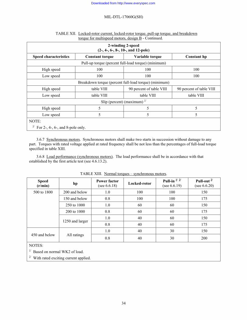
MIL-DTL-17060G(SH)
34
TABLE XII. Locked-rotor current, locked-rotor torque, pull-up torque, and breakdown torque for multispeed motors, design B - Continued.
2-winding 2-speed (2-, 4-, 6-, 8-, 10-, and 12-pole)
Speed characteristics Constant torque Variable torque Constant hp Pull-up torque (percent full-load torque) (minimum)
High speed 100 100 100 Low speed 100 100 100
Breakdown torque (percent full-load torque) (minimum) High speed table VIII 90 percent of table VIII 90 percent of table VIII Low speed table VIII table VIII table VIII
Slip (percent) (maximum) 1/ High speed 5 5 5 Low speed 5 5 5
NOTE: 1/ For 2-, 4-, 6-, and 8-pole only.
3.6.7 Synchronous motors. Synchronous motors shall make two starts in succession without damage to any
part. Torques with rated voltage applied at rated frequency shall be not less than the percentages of full-load torque specified in table XIII.
3.6.8 Load performance (synchronous motors). The load performance shall be in accordance with that established by the first article test (see 4.6.13.2).
TABLE XIII. Normal torques – synchronous motors.
Speed (r/min) hp Power factor
(see 6.6.18) Locked-rotor Pull-in 1/ 2/
(see 6.6.19) Pull-out 2/
(see 6.6.20) 500 to 1800 200 and below 1.0 100 100 150
150 and below 0.8 100 100 175 250 to 1000 1.0 60 60 150 200 to 1000 0.8 60 60 175 1.0 40 60 150
1250 and larger 0.8 40 60 175 1.0 40 30 150
450 and below All ratings 0.8 40 30 200
NOTES: 1/ Based on normal WK2 of load. 2/ With rated exciting current applied.
Downloaded from http://www.everyspec.com

MIL-DTL-17060G(SH)
35
3.6.9 Phase characteristic (synchronous motors). The load and no-load phase characteristic shall be in accordance with that established by the first article test (see 4.6.13).
3.6.10 Inclined operation. The mechanical balance of the motor shall not change, no pounding or grinding of the bearings shall occur, and the lubrication system shall meet the requirements of 3.6.2 (see 4.6.14).
3.6.11 Temperature rise. The requirements of 3.6.11.1 through 3.6.11.5 shall apply, as applicable (see 4.6.16).
3.6.11.1 Continuous duty. Motors rated for continuous duty (see 3.5.1.6) shall carry rated load continuously at the ambient temperature specified (see 3.5.1.3) without exceeding the allowable temperature rises in table XIV.
3.6.11.2 Intermittent duty. Motors rated for intermittent duty (see 6.6.4.2) shall carry rated load for the time duration which will permit operation of the motor indefinitely at the ambient temperature and the cycle of load, no-load, and rest specified (see 3.5.1.6) without exceeding the allowable temperature rises in table XIV. Where intermittent operation is involved and no definite operating cycle can be given, a short-time duty motor of sufficient rating to meet the estimated load and duty cycle requirements shall be required.
3.6.11.3 Varying duty. Motors rated for varying duty (see 6.6.4.3) shall carry rated load for the time duration which will permit indefinite operation of the motor at the ambient temperature and the cycle of varying loads specified (see 3.5.1.6) without exceeding allowable temperature rises in table XIV.
3.6.11.4 Short-time duty. Motors rated for short-time duty (see 6.6.4.4) shall carry rated load which, starting at the ambient temperature, can be carried constantly for the period specified (see 3.5.1.6) without exceeding allowable temperature rises in table XIV.
3.6.11.5 VSD motors. VSD motors shall comply with the following requirements, as applicable:
3.6.11.5.1 VSD motors operated without a VSD. VSD motors in accordance with 3.5.2.8.2 shall meet 3.6.11.1 or 3.6.11.3, as applicable, without a VSD, with 60 hertz power applied at a voltage per 3.5.1.2 (a) or (b).
3.6.11.5.2 VSD motors operated with a VSD. VSD motors in accordance with 3.5.2.8.2 shall meet 3.6.11.1 or 3.6.11.3, as applicable, when operated with a VSD. For continuous duty operation per 3.6.11.1 or varying duty operation, per 3.6.11.3, unless otherwise specified in 6.2, the applicable speed shall be the base speed and the rated load shall be the load at base speed for the auxiliary.
3.6.11.5.3 VSD motors with constant torque applications operated with a VSD. In addition to 3.6.11.5.1 and 3.6.11.5.2, VSD motors for constant torque applications shall meet table XIV when operated with a VSD at minimum operating speed at the resulting load requirement
3.6.11.5.4 VSD motors not in accordance with 3.5.2.8.2. VSD motors not in accordance with 3.5.2.8.2 shall meet 3.6.11.1 through 3.6.11.4, as applicable, when operated in accordance with the defined duty cycle with a VSD.
Downloaded from http://www.everyspec.com

MIL-DTL-17060G(SH)
36
TABLE XIV. Maximum temperature rises (°C) and measurement method. 1/ 6/
Maximum ambient temperature 104 °F(40 °C)
122 °F(50 °C)
149 °F (65 °C)
158 °F (70 °C)
176 °F (80 °C)
Insulation Class 7/ F F F H N F H N H N Item Motor part
1 Windings other than those in item 4: (a) Dripproof protected, fan cooled
and air over enclosures. Method 2 3/ 176 (80)
158 (70)
131(55)
176(80)
221(105)
122 (50)
167 (75)
212(100)
149(65)
194(90)
(b) Others. Method 2 3/ 185 (85)
167 (75)
140(60)
185(85)
230(110)
131 (55)
176 (80)
221(105)
158(70)
203(95)
2 Cores and mechanical parts in contact with or adjacent to the insulation:
(a) Motors in 1(a). Method 1 2/ 158 (70)
140 (60)
113(45)
158(70)
203(95)
104 (40)
149 (65)
194(90)
131(55)
176(80)
(b) Motors in 1(b). Method 1 2/ 167 (75)
149 (65)
122(50)
167(75)
212(100)
113 (45)
158 (70)
203(95)
140(60)
185(85)
3 Bare copper winding and single layer field windings with exposed uninsulated surfaces:
(a) Motor in 1(a). Method 1 2/ 176 (80)
158 (70)
131(55)
176(80)
221(105)
122 (50)
167 (75)
212(100)
149(65)
194(90)
(b) Motors in 1(b). Method 1 2/ 185 (85)
167 (75)
140(60)
185(85)
230(110)
131 (55)
176 (80)
221(105)
158(70)
203(95)
4 Bearing, ball 5/. Method 1 or 3 2/ 4/ 122 (50)
104 (40)
95 (35)
104 (30)
68 (20)
Bearing, sleeve 5/. Method 3 4/ 122 (50)
104 (40) -------- -------- --------
Bearing oil sump. Method 1 or 3 2/ 4/ 104 (40)
104 (30) -------- -------- --------
NOTES: 1/ Squirrel-cage and mechanical parts (such as pole tips) may attain such temperatures as will not injure the motor in any
respect. 2/ As determined by temperature measurement Method 1 of MIL-E-917. 3/ As determined by temperature measurement Method 2 of MIL-E-917. 4/ As determined by temperature measurement Method 3 of MIL-E-917. 5/ Bearing temperatures measured on bearing outer ring or Babbitt. 6/ For VSD motors operating at minimum speed, add 5 degrees to the temperature rise limits. 7/ Insulation class per MIL-E-917.
Downloaded from http://www.everyspec.com

MIL-DTL-17060G(SH)
37
3.6.12 Dielectric strength. Motors shall withstand dielectric test voltages specified in table XV (see 4.6.17).
TABLE XV. Dielectric test voltages.
Part Test voltage Minimum duration Secondary windings of wound rotors: Nonreversing 1,000 plus twice normal induced voltage on
open circuit 1 minute
Reversing, while running at approximately normal speed by reversing the primary connections.
1,000 plus four times normal induced voltage on open circuit
1 minute
To be started with the field open circuited and sectionalized
1.5 times the maximum r/min voltage which can occur between the terminals of any section but in no case less than 2500 volts or 10 times the rated excitation voltage per section, whichever is the larger
1 minute
All others: Motors rated more than 600 volts 2,000 plus 2.25 times rated voltage. 1 minute Motors rated 600 volts or less 1,000 plus twice rated voltage or 1,200 plus 2.4
times rated voltage 1 minute 1 second
3.6.13 Electrical balance. With balanced voltage applied, amperes in any phase at rated load shall not differ
from the arithmetic average of the maximum and minimum phase amperes by more than 10 percent for motors rated 1½ hp and under; by more than 7½ percent for motors rated 2 and 3 hp; and by more than 5 percent for motors over 3 hp (see 4.6.18).
3.6.13.1 For submarine applications. The maximum deviation of any phase current from the average of all phase currents shall be not greater than 3 percent (see 4.6.18).
3.6.14 Efficiency. Efficiency requirements apply to design A, B, and B7 continuous duty motors, only. Design A, B, and B7 continuous duty motors shall meet the requirements of 3.6.14.1 through 3.6.14.5.
3.6.14.1 Single speed motors. Single speed design A and B7 motors shall have a minimum full-load efficiency as specified in table XVI. Single speed design B motors shall have full-load efficiencies reduced by not more than 1 percentage point from that specified in table XVI.
3.6.14.2 Multispeed motors. Multispeed design A and B7 motors shall have full-load efficiencies reduced by not more than 3 percentage points from that specified in table XVI for the highest speed only. Multispeed design B motors shall have full-load efficiencies reduced by not more than 4 percentage points from that specified in table XVI for the highest speed only. Efficiencies for all other speeds need not be as specified in table XVI.
3.6.14.3 Motors with shaft seals. Motors with shaft seals shall meet the efficiency requirements of 3.6.14.1 through 3.6.14.5 either with or without seals.
3.6.14.4 VSD motors. Only VSD motors meeting the requirements of 3.5.2.8.2 have an efficiency requirement. These VSD motors shall have a minimum efficiency at rated horsepower of not less than 2 percentage points below the appropriate value of table XVI. The speed used in determining the appropriate value in table XVI is the base speed. Rated horsepower is the horsepower output requirement at base speed (see 6.2).
3.6.14.5 Non-standard hp ratings. Design A, B, and B7 motors furnished in hp ratings other than those specified in table XVI shall have full-load efficiencies as specified in 3.6.14.1 through 3.6.14.5 for the next lower hp rating.
Downloaded from http://www.everyspec.com

MIL-DTL-17060G(SH)
38
3.6.15 Partial discharge inception voltage and rise time (for variable speed drive motors). Partial discharge inception voltage (see 6.6.15) shall be greater than 3000 volts when tested in accordance with 4.6.22.
3.6.16 Electromagnetic interference requirements (for variable speed drive motors). Motor shall pass test RE102 in MIL-STD-461 (see 4.6.23). The purpose of this test is to ensure the motor terminal box is properly sealed to meet EMI requirements (see 6.6.6)
3.6.17 Electromagnetic interference requirements for motors with thermal protection systems. Motors with thermal protection systems shall operate successfully, without false tripping in the electromagnetic environment identified in MIL-STD-461 (see 4.6.24).
TABLE XVI. Minimum motor efficiency.
Enclosure DPP All other
Synchronous speed (rated hp) ≥ 1200 r/min ≤ 900 r/min ≥ 1200 r/min ≤ 900 r/min
≥ 200 97.0 95.0 97.0 95.0 150 96.5 94.5 97.0 95.0 125 96.0 94.0 97.0 95.0 100 95.5 93.5 96.5 94.5 75 95.0 93.0 96.0 94.0 60 94.0 92.0 95.5 93.5 50 94.0 92.0 95.0 93.0 40 93.0 91.0 95.0 93.0 30 92.0 90.0 94.0 92.0 25 92.0 90.0 94.0 92.0 20 92.0 90.0 93.0 91.0 15 91.0 89.0 93.0 91.0 10 90.0 88.0 92.0 90.0 7.5 90.0 88.0 91.0 89.0 5 89.0 87.0 89.0 87.0 3 88.0 86.0 88.0 86.0 2 87.0 85.0 87.0 85.0
1.5 86.0 84.0 86.0 84.0 1 86.0 84.0 86.0 84.0
4. VERIFICATION
4.1 Classification of inspections. The inspection requirements specified herein are classified as follows:
a. First article inspection (see 4.2) b. Conformance inspection (see 4.3) c. Periodic inspection (see 4.4)
Downloaded from http://www.everyspec.com

MIL-DTL-17060G(SH)
39
4.2 First article inspection. Prior to the offering of any identical production unit for acceptance by the Government, one motor shall have successfully undergone first article inspection as described herein. First article inspection shall consist of the inspections specified in table XVIII. A complete first article inspection shall be required after any change in design, material, or process which affects the performance characteristics of the motor.
4.2.1 Sealed insulation system suitability inspection. Suitability shall be determined through certification as described in 4.6.19.1. Once a sealed insulation system has been qualified as specified in 4.6.19.1, recertification is required in accordance with MIL-STD-2037.
4.3 Conformance inspection. Conformance inspection as specified in table XIX shall be performed on all motors offered for delivery on a contract or order.
4.4 Periodic inspection. Samples for periodic inspection shall be randomly selected as specified in table XVII. Periodic inspection shall consist of the inspections specified in table XVIII. Sampling for periodic inspection shall be based on the number of motors of identical design and rating offered in the previous 12 months. Sampling shall also be based on the number of motors of identical design and rating that were sampled in the previous 12 months. If a motor has been submitted for first article inspection in the same 12 months as additional motors of an identical design and rating offered for delivery, the motor shall be considered in figuring succeeding quantities for periodic sampling.
4.5 Inspection conditions. Unless otherwise specified herein (see 4.6.14), all inspections shall be performed under the test conditions specified below; ambient conditions shall be within these ranges but need not otherwise be controlled:
a. Temperature – 77±59 °F (25±15 °C). b. Power input – rated voltage and frequency (see 3.5.1.2). c. Attitude – normal operating position except as directed herein.
4.6 Noncompliance. Any motor with one or more defect shall be rejected. In addition, if any motor fails to pass an inspection, the manufacturer shall notify the cognizant inspection activity of such failure and take corrective action on the materials or processes, or both, as warranted, and on all units of the product which can be corrected and which were manufactured with essentially the same materials and processes, and which are considered subject to the same failure. Acceptance and shipment of the product shall be discontinued until corrective action, acceptable to the cognizant activity, has been taken. In the event of failure after reinspection, the manufacturer shall notify the cognizant inspection activity of the failure.
TABLE XVII. Sampling for periodic inspection.
Number of motors (offered last 12 months) Sample size
1-12 1 13-25 2 26-50 3 51-90 4
91-150 5 151-280 6
Downloaded from http://www.everyspec.com

MIL-DTL-17060G(SH)
40
TABLE XVIII. First article inspection.
Inspection Requirement Test method Material (if specified)
Service A 3.5.2.1.1 4.6.1 Service C 3.5.2.2 4.6.1
Assembly Appendix A 4.6.2 Resistance (cold) 3.6.1 4.6.3
Lubrication 3.6.2 4.6.4 Noise
Airborne 3.6.3.1 4.6.5.1 Structureborne 3.6.3.2 4.6.5.2
Mechanical balance Service A 3.5.2.1.12 4.6.6 Service C 3.5.2.2.4 4.6.6
End play – sleeve bearing motors 3.5.1.22.5.6 4.6.7.1 Ball bearing motors
Service A 3.5.2.1.5 4.6.7.2 Service C 3.5.2.2.3 4.6.7.2
Effectiveness of enclosure 1/ 3.5.1.8 4.6.8 Weight 3.6.4 4.6.9 No-load input (induction motors) 3.6.5 4.6.10 Pull-up torque, breakdown torque, lock-rotor torque, and current (induction motors)
3.6.6 4.6.11
Load test (induction motors only) 3.5.1.12 4.6.12 Phase characteristic (synchronous motors)
No-load test 3.6.9 4.6.13.1 Load test 3.6.8 4.6.13.2
Inclined operation (sleeve bearing and oil lubricated ball bearing motors only)
3.6.10 4.6.14
Shock 1/ Service A 3.5.2.1 4.6.15 Service C 3.5.2.2 4.6.15
Heat run 3.6.11 4.6.16 Dielectric strength 3.6.12 4.6.17 Electrical balance 3.6.13 4.6.18
Downloaded from http://www.everyspec.com

MIL-DTL-17060G(SH)
41
TABLE XVIII. First article inspection – Continued.
Inspection Requirement Test method Sealed insulation system suitability 1/ 3.5.1.31 4.6.19.1 Efficiency 3.6.14 4.6.20 Preload device (submarine motors with special pre-load requirements only)
3.5.2.5.13 4.6.21
Sealed insulation system – electrical (VSD motors only) Partial discharge inception voltage and rise time Electromagnetic interference
3.5.1.31
3.6.15
3.6.16
4.6.19.2
4.6.22
4.6.23 Inspection of packaging 5 4.7 NOTE:
1/ These are one-time tests and need not be repeated once satisfactorily demonstrated unless either material or processes change.
Downloaded from http://www.everyspec.com

MIL-DTL-17060G(SH)
42
TABLE XIX. Conformance inspection.
Inspection Requirement Test method Group A Material (if specified)
Service A 3.5.2.1.1 4.6.1 Service C 3.5.2.2 4.6.1
Assembly Appendix A 4.6.2 Resistance (cold) 3.6.1 4.6.3 Lubrication 3.6.2 4.6.4 Preload device (submarine motors with special pre-load requirements only)
3.5.2.5.13 4.6.21
Group B Structureborne noise 3.6.3.2 4.6.5.2 Mechanical balance
Service A 3.5.2.1.12 4.6.6 Mechanical balance, continued.
Service C 3.5.2.2.4 4.6.6 End play
Sleeve bearing motors 3.5.1.22.5.6 4.6.7.1 Ball bearing motors 3.5.2.1.5 and 3.5.2.2.3 4.6.7.2 No-load input (induction motors) 3.6.5 4.6.10
Phase characteristic (synchronous motors)
No-load test 3.6.9 4.6.13.1 Dielectric strength 3.6.12 4.6.17 Sealed insulation system – electrical
3.5.1.31 4.6.19.2
4.6 Test methods.
4.6.1 Materials. The Government may require material tests whenever it considers it necessary to ascertain that the quality of a material used is at least equal to the material specified herein and covered by the referenced specifications, or as shown on the manufacturer’s drawing.
4.6.2 Assembly.
4.6.2.1 Service A motors. The inspections for Service A motors shall be as specified in Appendix A herein.
4.6.2.2 Service C motors. Each motor shall be visually examined to determine that construction and workmanship conform to the requirements specified herein. The fit of parts shall be examined to determine the interchangeability of parts which may require replacement during the service life of the motor.
4.6.3 Resistance (cold). With the motor not operating and at the ambient temperature, each terminal-to-terminal winding resistance (cold) and the ambient temperature shall be measured.
Downloaded from http://www.everyspec.com

MIL-DTL-17060G(SH)
43
4.6.4 Lubrication. The effectiveness of the lubricating system with the motor in its normal position shall be observed during the progress of the other tests, or by special test, as applicable. Oil rings of sleeve bearing motors shall turn freely and there shall be no foaming of the oil. Lubricants similar to those required for service operation shall be used. It shall be demonstrated that the motor lubrication is satisfactory, that the specified limitations of the bearing temperatures have not been exceeded, and that there is no suction of lubricant into the electrical windings under any operating condition.
4.6.5 Noise.
4.6.5.1 Airborne noise. Airborne noise shall be measured using the instrumentation and procedures of MIL-STD-740-1 with the exception that noise levels at the measurement positions shall be averaged. Except as required in 4.6.5.3, motors shall be tested while operating at no-load with rated voltage and frequency applied.
4.6.5.2 Structureborne noise. Except as required in 4.6.5.4, motors with structureborne noise requirements shall be tested at no-load with rated voltage and frequency in accordance with MIL-STD-740-2 with the exception that quality testing shall be conducted at the transducer location which produced the maximum response during first article testing.
4.6.5.3 Airborne noise for VSD motors. VSD motors shall be tested per 4.6.5.1 with the exception that testing shall be at the maximum specified operating speed as follows:
a. If the maximum operating speed (see 6.2) is greater than the base speed (see 6.6.25.6), testing shall be performed at the maximum operating speed at no-load with a VSD.
b. If the maximum operating speed is less than or equal to the base speed, testing shall be performed at the base speed at no-load using a VSD or facility power.
4.6.5.4 Structureborne noise for VSD motors. VSD motors shall be tested per 4.6.5.2 with the exception that testing shall be performed with a VSD at the volts per hertz point to operate no-load at the following conditions:
a. Testing shall be performed at the specified maximum operating speed (see 6.2). If a maximum operating speed is not specified, testing shall be done at the base speed (see 6.6.25.6).
b. Structureborne noise shall be sampled across the speed range. If the noise at a speed within the range is greater than the noise measured in 4.6.5.4(a.), testing shall also be performed at the speed within the speed range with the greatest noise levels.
4.6.6 Mechanical balance. The mechanical balance of the completely assembled motor and any special attachments (such as brakes or overspeed switches) shall be measured. Motors shall be tested at no-load, except motors having a varying speed (but not a definite no-load speed) shall be tested at their highest rated speed. The method of test shall be as follows:
a. The motor shall be mounted on an elastic mounting so proportioned that the up and down natural frequency shall be at least as low as one-quarter of the maximum operating speed of the motor. To accomplish this, the elastic mounting shall be deflected downwards at least by the following amounts due to the weight of the motor. The deformation of the mounting shall be not more than one-half the original height of the elastic element.
r/min Compression (inch)
900 1
1,800 ¼
3,600 1/16
7,200 1/64
b. Prior to assembly, the rotor shall be balanced in a balancing machine with or without bearings. If balanced with bearings, the inside bearing caps shall be supported on the shaft during balancing. Balancing shall be accomplished in two planes for both static and dynamic correction.
c. A vibration indicator shall be used.
Downloaded from http://www.everyspec.com

MIL-DTL-17060G(SH)
44
d. With the motor running at rated input voltage and frequency and the axis of the shaft in its normal position, the amplitude of vibration of the bearing housing in the direction giving the maximum amplitude shall be measured and recorded. The motor shall be balanced with one-half standard key in keyway (that is, a key of full length flush with the top of the keyway, where applicable).
4.6.7 End play.
4.6.7.1 Sleeve bearing motors. The end play of horizontal sleeve bearing motors shall be measured while at standstill by alternately pressing and releasing the rotor shaft at each end.
4.6.7.2 Ball bearing motors. The end play of ball bearing motors shall be determined by clamping an indicator to the motor frame and measuring axial shaft movement while applying an axial force to the shaft. The force shall not exceed 150 percent of the weight of the rotor assembly. The shaft shall be moved through its free travel and readings shall be taken. For heavy rotors, the motor may be lowered onto its shaft in a vertical position and the weight of the motor released slowly onto the shaft and displacement measured. Enough weight shall be released to support the motor without distorting the end shields. The process shall be repeated to confirm measurements.
4.6.8 Effectiveness of enclosure. Enclosed motors shall be tested in accordance with MIL-E-2036 and MIL-STD-108 except that the drip test for a dripproof protected enclosure is not required.
4.6.9 Weight. The weight of motor and rotor shall be measured and shall conform to 3.6.4.
4.6.10 No-load input (induction motors only). Measurements of line volts and amperes, watt inputs, and rotational speed shall be taken. The motor shall be run for a minimum of 1 hour to allow bearing losses to become constant before any readings are taken. Where the rotor of the motor is supported by the bearings of the driven auxiliary, this test may be conducted with the motor driving the auxiliary with the auxiliary unloaded.
4.6.11 Pull-up, breakdown, and locked-rotor torque and current (induction motors).
4.6.11.1 Test with motor operating at rated voltage. For motors rated at 60 hp or less, pull-up and breakdown torque and locked-rotor current and torque shall be measured with the motor operating at rated voltage. For motors rated in excess of 60 hp, testing should be performed at rated voltage with the exception that locked-rotor torque and current may be measured with the motor operating at less than rated voltage as specified in 4.6.11.2 if testing at rated voltage would exceed the kilovoltamperes (kVA) limits of the test facility. Readings of voltage, current, watts, and torque shall be taken. For locked-rotor torque and current test, the locked-rotor condition shall be maintained for 20 seconds at rated voltage unless locked-rotor torque and current values are obtained by 4.6.11.2. When locked-rotor torque and current values are obtained from tests at less than rated voltage, the locked-rotor capacity shall be demonstrated by 4.6.11.2. Tests shall be initiated with motor at room ambient temperature.
4.6.11.2 Test with motor operating at less than rated voltage. Locked-rotor torque and current values shall be obtained with motor operating at the maximum kVA available at rated frequency. If the locked-rotor current varies with rotor position, the rotor shall be locked in the position where the locked-rotor current is equal to the mean of the maximum and minimum values. Readings of input voltage, current, watts, and torque values. The test shall be repeated at voltages producing approximately half and one-quarter of the locked-rotor current measured at maximum kVA. Input voltage, current, watts, and torque shall be measured. The proportion of current shall be adjusted such that the minimum locked-rotor current shall be not less than the full-load motor current at rated load. The locked-rotor current, corrected to rated voltage, shall be determined by the following equations:
For enclosed rotor slots:
I1r = I1 × (Vr / V1) β
where:
β = 0.7α + 0.35
and
α = log(I3 / I1) / log(V3/ V1)
Downloaded from http://www.everyspec.com

MIL-DTL-17060G(SH)
45
For semi-enclosed and open rotor slots:
I1r = 1.04 × I3 × (Vr / V3) σ
where:
σ = 1.05σ2 – 0.35(σ1 – 1) for σ2 > σ1
or
σ = 0.7σ2 + 0.35 for σ2 ≤ σ1
and
σ1 = log(I2 / I1) / log(V2 / V1)
σ2 = log(I3 / I2) / log(V3 / V2)
The locked-rotor torque, corrected to rated voltage, shall be the minimum of the three values determined by the following equation:
T1r = Tm × (Vr / Vm) β
where:
β = log(Tm / Tn) / log(Vm / Vn)
and
m = 3, n = 2; m = 3, n = 1; m = 2, n = 1
To conform to the requirement to lock the rotor for 20 seconds at rated voltage, the rotor shall be locked at reduced voltage, V3, for a time in seconds determined by the following equation:
tLR = 20 × (Vr × I1r) / (V3 × I3)
The values for the above equations are:
I1r = locked-rotor current at rated voltage
I3 = locked-rotor current measured at maximum kVA of test facility
I2 = measured locked-rotor current intermediate to I3 and I1
I1 = lowest value of measured locked-rotor current, not less than rated current
Vr = rated voltage
V3 = measured locked-rotor voltage at maximum kVA of test facility
V2 = measured locked-rotor voltage associated with I2
V1 = measured locked-rotor voltage associated with I1
T1r = locked-rotor torque at rated voltage
T3 = measured locked-rotor torque at maximum kVA of test facility
T2 = measured locked-rotor torque associated with locked-rotor voltage V2
T1 = measured locked-rotor torque associated with locked-rotor voltage V1
tLR = period of time, in seconds, with rotor locked at voltage, V3
Downloaded from http://www.everyspec.com

MIL-DTL-17060G(SH)
46
4.6.12 Load test (induction motors only). With the motor operating at rated voltage and frequency, simultaneous measurements of each line to line voltage, frequency, amperes in each phase, rotational speed, and input watts shall be taken at 0, ¼, ½, ¾, 4⁄4 and 5⁄4 of rated hp. The hp load may be determined by current or watt input or by torque. The motor shall be at approximately its normal operating temperature during these tests.
4.6.13 Phase characteristic (synchronous motors only).
4.6.13.1 No-1oad test. The no-load test consists of taking a series of measurements of armature amperes, field amperes, and field voltage as the field current is varied from zero to a value that produces 150 percent of rated armature amperes. A measurement of amperes in all phases shall be taken with zero field. Sufficient measurements to plot a “vee curve”, that is, armature amperes against field amperes, shall be taken. The watts input at the minimum value of stator amperes shall check the sum of the stator copper, core, friction, and windage losses. This test shall be conducted at rated voltage and rated frequency.
4.6.13.2 Load characteristics test. The load characteristics test shall be similar to the no-load test except that measurements need not be obtained for zero field. Unless otherwise specified (see 6.2), this test shall be conducted under rated load conditions.
4.6.14 Inclined operation (sleeve bearing and oil lubricated ball bearing motors only). Under each of the positions of inclination specified in 4.6.14.1 and 4.6.14.2, the motor shall be run for a period of not less than 30 minutes for surface ship motors and 1 hour for submarine motors. This test may be made on the combined motor and driven auxiliary. The motor or combined motor-driven auxiliary shall be run at not less than its maximum service speed, and the driven auxiliary need not be loaded. During the progress of these tests it shall be ascertained that the mechanical balance is as good as it was in the normal horizontal position, that there is no pounding or grinding at the bearings, and that the lubrication is satisfactory. If the motor is provided with oil-ring lubrication, it shall be ascertained that the rings do not rub or strike against the sides or ends of the oil well, that they do not “dance” or show pronounced irregularity of movement, and that the shaft does not sling oil into the motor. For submarine motors, the bearing or lubricating oil temperature at the completion of test shall be measured. Additionally, the suitability of the motor for operation when a ship is rolling 45 degrees for surface ships and 60 degrees for submarine motors to either side shall be determined by inspection of design.
4.6.14.1 Horizontal motors. The inclination test positions for horizontal motors shall be as follows:
a. Surface ship motors: (1) Shaft inclined 15 degrees, front end low (2) Shaft inclined 15 degrees, rear end low (3) Shaft horizontal, motor base tilted 15 degrees to the right (4) Shaft horizontal, motor base tilted 15 degrees to the left
b. Submarine motor inclination test shall be the same as in 4.6.14.1a except that inclinations shall be 45 degrees.
4.6.14.2 Vertical motors. Vertical motors shall be tested by inclining them to an angle of 15 degrees for surface ship motors and 45 degrees for submarine motors from their normal position, in any direction (that direction which imposes the most severe condition, if there is any dissymmetry) and for a period of 30 minutes for surface ship motors and 1 hour for submarine motors. This test may be made on the combined unit used for the special operating test. Vertical motor-driven auxiliaries shall be tested by inclining them to an angle of 15 degrees for surface ship units and 45 degrees for submarine units from their normal position, in each of four different directions; namely, forward, backward, to the right, and to the left. Observations shall be made as specified in 4.6.14 for horizontal motors and combined motor-driven auxiliaries.
Downloaded from http://www.everyspec.com

MIL-DTL-17060G(SH)
47
4.6.15 High-impact shock test. Tests for lightweight motors shall be nine blows delivered while the motor is operating under no-load at nominal speed. An additional nine blows shall be delivered with the motor stationary; separate motors may be submitted for each series of nine blows if desired by the contractor. Tests specified in MIL-S-901 under group I and group III in the horizontal and inclined orientation for medium weight motors shall be conducted with the motor running under no-load at nominal speed. Tests under group II shall be with the motor stationary. For inclined orientation, medium weight motors shall be mounted with the motor shaft axis inclined and shaft extension up. Separate motors may be submitted for each series of three blows if desired by the contractor. Tests shall be as specified in MIL-S-901 and with other features of the test as follows:
a. Required type of shock test. Type A, B, or C as specified (see 6.2). b. Weight designation of the shock test (as required by the motor). Motors weighing 250 pounds or less shall
be tested on the lightweight shock testing machine. Motors weighing in excess of 250 pounds and up to 6,000 pounds shall be tested on a medium weight shock testing machine. Motors weighing over 6,000 pounds shall be tested on a floating shock test platform. When a motor shaft supports a part of a driven auxiliary, such as a pump impeller or a clutch-type coupling, the motor shall be shock tested with the shaft loaded with the part or with an equivalent weight for that part.
c. Required class of equipment. Unless otherwise specified (see 6.2), Class I. d. Required grade of equipment. Grade A for Service A motors or Grade B for Service C motors (see 6.2). e. Method of mounting on shock-testing machine. Mounting adapters shall be as shown on the applicable
figures of MIL-S-901.
4.6.15.1 Post-shock analysis. Following completion of the shock test, the following examinations shall be performed on the motor in the order given below:
a. Visual inspection (external). Service A and C motors shall be visually inspected without disassembly for breakage, distortion, deformation, and dislocation of any parts.
b. Heat run. Service A motors shall be operated at full load (at rated speed) with rated input voltage and frequency applied for not less than 4 hours. Bearing and oil temperature rises shall be determined as specified in 4.6.16. During this test, any unusual motor noises (e.g., squeals, grinding, or pounding) shall be noted.
c. Dielectric strength. For Service A and C motors, a dielectric strength test as specified in 4.6.17 shall be performed immediately following the heat run. However, the applied voltage shall be 65 percent of the values in table XV.
d. Internal inspection. Service A motors shall be disassembled and inspected thoroughly for damage (such as breakage, distortion, deformation, or dislocation of parts). The extent of disassembly shall be sufficient to observe the condition of all parts including, be not limited to, the structure, bearings, and winding. The causes of any increase in motor airborne noise shall be determined.
4.6.15.2 Failure to perform principal functions. Any of the following shall be cause for rejection of the motor:
a. Service A motors: (1) Breakage of any parts, including mounting bolts. (2) Appreciable distortion or dislocation of any parts such as mounting feet, poles, coils, and bearings. (3) Values of speed differing by more than 1 percent of the preshock test values, and no-load input watts
increasing by more than 5 percent. If no-load watts decrease by more than 10 percent, this does not constitute a failure, but rationale shall be provided explaining this reduction.
(4) A mechanical imbalance of more than two times the applicable value specified in table V. (5) Either a bearing or oil temperature rise or both in excess of that permitted in table XIV. (6) Any unusual motor noises (e.g., squeals, grinding or pounding) when operating. The cause of such
noise shall be determined. (7) Insulation failures during the dielectric strength test of 4.6.15.1(c).
b. Service C motors:
Downloaded from http://www.everyspec.com

MIL-DTL-17060G(SH)
48
(1) The motor comes adrift during exposure to HI shock. Motor parts come adrift with the exception of parts that remain within the motor.
(2) Insulation failures during the dielectric strength test of 4.6.15.1.c.
4.6.15.3 Disposal of shock-tested motors. Motors which have failed to pass the high-impact shock test shall not be acceptable, either as a whole or in any of the parts. However, motors which have passed the high-impact shock test shall be considered acceptable as an item in the contract, provided the post-shock tests are passed and the mechanical corrective measures below are accomplished. Minor deformations shall be those which do not cause unqualified rejection of the design under the high-impact shock test but are in excess of the dimensional tolerances specified on the applicable motor drawing.
a. Mounting flanges connecting directly to the driven auxiliary shall be replaced in the event of minor deformation.
b. Minor deformations affecting alignments (including alignments with the auxiliary) shall be corrected. c. All ball bearings shall be replaced. d. Service C motors shall be restored to operational condition and shall be inspected as specified in 4.6.15.l(b)
and (d).
4.6.15.4 Shock extension. Motor shock test acceptance may be extended upon approval (see 6.11 and Appendix D), based on the following:
a. If the acceptance of the tested motor is based on a Type A (combined motor and auxiliary) test, acceptance may be extended to the same motor when applied to a different auxiliary if the accepted and proposed motor-auxiliaries employ a flexible coupling and the auxiliaries are of the same basic type; for example, pumps or fans.
b. Shock acceptance of a motor based on a Type A test is not extendable to a different motor. c. Shock acceptance of a motor based on a Type B (motor only) test may be extendable to another motor
based on the following: (1) The core length and shaft extension of the accepted motor shall be not less than that of the motor
proposed for extension. (2) The shaft extensions of the accepted and proposed motors shall have similar configurations. The shaft
height, “d” dimension (see figures 1 through 4), shall be identical. (3) The motor configurations shall be similar.
4.6.15.5 Waiver. Where the motor will be shock tested as part of an overall package, shock test of the motor alone is not required.
4.6.16 Heat-run test. The heat-run test for motors shall utilize embedded thermocouples in accordance with the following and Methods 1 and 2 of MIL-E-917 for the first article test. Periodic tests may be in accordance with Method 2 of MIL-E-917. The heat-run test for continuous duty motors shall be in accordance with the following:
a. Rated motor load - 100 percent b. Voltage and frequency - rated c. Time - until motor temperatures are constant
Motor load may be obtained by maintaining the current or watt input corresponding to rated motor hp output.
Downloaded from http://www.everyspec.com

MIL-DTL-17060G(SH)
49
4.6.16.1 Details of temperature tests. Normal load heat runs on continuous duty motors shall be continued until constant temperatures have been attained in all parts of the motor. For motors having several continuous ratings, the heat run shall be conducted using the rating giving the highest temperature rises. In cases where the highest temperature rises cannot be determined prior to the test, the motor shall be tested separately for each rating. Temperature measurements by thermocouple shall be used during the progress of the heat run to determine when the constant operating temperature has been reached. It shall be considered that constant temperatures have been reached when at least three consecutive readings taken at 15-minute intervals show no increase in the temperature in any part of the motor, when adjusted for changes in ambient temperature. The winding temperature rise shall then be determined in accordance with the procedures for Method 2 of MIL-E-917. The bearings’ temperature rise shall be determined in accordance with the procedures of Methods 1 or 3 of MIL-E-917.
4.6.16.2 Duration of temperature test. The duration of the temperature test of a motor with a short-time or overload requirement shall be the time specified for that rating. Intermittent and varying duty motors shall be tested at the specified duty cycle. In lieu thereof, the motors may be tested as short-time duty motors of sufficient rating to meet the actual load requirements.
4.6.16.3 Use of temporary air filters. When temporary air filters are to be used, the tests of 4.6.16.1 shall be repeated with the filter media specified (see 3.5.2.1.12) attached to the air intakes. Three thicknesses of filter media shall be used to simulate a loaded or dirty filter. Temperature limits of table XIV shall apply.
4.6.16.4 Heat run measurements. The following measurements shall be made for each heat run test:
a. Motor input voltage and current, watts and revolutions per minute. b. Motor output power (may be calculated using current, torque, or watt inputs). c. Temperatures measured concurrently as follows:
(1) Motor parts as required in table XIV (2) Room ambient
4.6.16.5 Measurement of temperature rise. The temperature rise of each motor component part shall be determined immediately at the conclusion of the heat run. Temperature rise (see table XIV) shall be determined in accordance with Method 1 (thermometer), Method 2 (resistance), and Method 3 (embedded detector) of MIL-E-917. In determining temperature rise, no correction shall be made for barometric pressure, humidity, or for any differences in heat transfer characteristics between the test ambient temperature and the maximum design ambient temperature.
4.6.16.6 Variable speed drive motor. Heat run testing for Variable Speed Drive (VSD) motors shall comply with the following:
a. VSD motors meeting 3.5.2.8.2, driving pumps, fans, or compressors, shall be tested with a VSD. Testing shall be performed at the maximum operating speed and at the horsepower rating associated with maximum operating speed (see 6.2).
b. VSD motors for constant torque applications shall be tested with a VSD at the minimum operating speed at the horsepower rating associated with minimum speed.
c. VSD motors meeting 3.6.11.5.4 shall be tested with the VSD at the specified duty cycle.
4.6.17 Dielectric tests. The dielectric test shall be conducted after all other tests have been completed. The frequency of the testing voltage shall be not less than 60 hertz and shall approximate a sine wave. If the insulation resistance of the windings is known to be lower than specified, due to dirt or moisture or damage to windings, this shall be remedied before the application of the dielectric test voltage. The dielectric test shall be conducted on the completely assembled machine and not upon individual parts. An exception is made in case of repair parts which require dielectric test; for example, repair coils and repair rotating elements with insulated windings. In the case of motors using capacitors, the dielectric test on the motor may be conducted with the capacitor disconnected. The capacitor shall be given a separate dielectric test according to the rating of the capacitor used.
Downloaded from http://www.everyspec.com

MIL-DTL-17060G(SH)
50
4.6.17.1 Measurement of test voltage. The measurement of the voltage used in dielectric tests shall be made by the voltmeter method whereby the instrument derives its voltage from the high-volt circuit either directly or by means of a voltmeter coil placed in the testing transformer, or through an auxiliary ratio transformer. In any case, if the capacitance of the machine to be tested is such as to cause wave distortion, the testing voltage shall be checked by a crest-voltage meter. If the crest-voltage meter is calibrated in crest volts, its reading shall be reduced to the corresponding rms sinusoidal value by multiplying by 0.707.
4.6.17.2 Points of application. Test voltage shall be successively applied between each electric circuit and all other electric circuits and metal parts grounded. Test voltage shall be applied in such a manner as to preclude the possibility of pitting the bearings in case of insulation failure. Voltage need not be applied between stationary and rotating windings.
4.6.18 Electrical balance. Line currents measured during the heat run test of 4.6.16 shall be used to demonstrate conformance to the electrical balance requirement of 3.6.13.
4.6.19 Sealed insulation system.
4.6.19.1 Sealed insulation system certification. Prior to motor delivery, certification of the sealed insulation system shall be demonstrated by the manufacturer through certification in accordance with MIL-STD-2037. Upon demonstration of compliance with MIL-STD-2037, NAVSEA will issue a letter of certification. This letter shall be evidence of certification for motors with a sealed insulation system.
4.6.19.2 Sealed insulation system - electrical. Sealed insulation systems shall be tested as follows:
a. Insulation resistance (submergence). Each wound assembly including lead connections shall be submerged for 24 hours in fresh water with a minimum conductivity of 500 microsiemens/cm and a maximum surface tension of 31 dynes/cm at 77 °F (25 °C). Wound assemblies with commutators or slip rings should be submerged to a point where the water level is as close as possible to the uninsulated areas.
(1) The conductivity of the fresh water may be increased by adding bicarbonate of soda to the water (salts are not used due to corrosive effects). The surface tension may be adjusted by addition of a wetting agent such as Triton X-100 (manufactured by Rohm and Haas, Philadelphia, PA) or equivalent.
(2) The dry insulation resistance should be verified to be not less than 1000 megohms prior to submergence. While submerged, as a minimum, the insulation resistance shall be measured after 1 minute, 10 minutes, 1 hour, and 24 hours. Insulation resistance shall also be measured immediately after removal from submergence, and one hour after removal from submergence. Values of insulation resistance shall be corrected to 77 °F (25 °C) and shall be in accordance with 3.5.1.31. Insulation resistance shall be measured using a 500 Vdc potential between the windings and ground.
b. Insulation resistance (dry). Apply a test potential of 500 Vdc between the windings and ground until a stable reading is obtained, but not less than 1 minute. Measure the insulation resistance and the average winding temperature. If the winding is at ambient temperature, a measurement of the ambient temperature may be substituted for that of the winding temperature. A megohm bridge or meter shall be used with a range of 0.1 to 1,000,000 megohms. Insulation resistance measurements shall be corrected to 77 °F (25 °C) and shall be as specified in 3.5.1.31.
c. Surge comparison. A commercial surge comparison tester with a minimum operating voltage range of 0 to 5,000 volts shall be used. The comparison tester shall be connected to the stator windings in and the test voltage shall be adjusted to 5,000 volts in accordance with the facilities procedure approved in accordance with MIL-STD-2037.
4.6.20 Efficiency. The efficiency test shall be conducted as specified in Appendix C. 4.6.20.1 Efficiency testing for VSD motors. Efficiency testing for VSD motors shall be conducted per 4.6.20
at base speed (see 6.6.25.6). The horsepower test point is the horsepower requirement at base speed (see 6.2).
4.6.21 Preload device. This test is applicable to submarine motors with special preload requirements (see 6.2). The uncompressed length of the preload device shall be measured before and after being fully compressed. The force required to compress the preload device shall be measured for the nominal design value of compression associated with the preload device’s intended application.
Downloaded from http://www.everyspec.com

MIL-DTL-17060G(SH)
51
4.6.22 Partial discharge inception voltage (for inverter duty insulation systems). Partial discharge inception voltage (see 6.6.2) shall be measured in accordance with IEC 61934 and IEC 60034-18-41. The environment the motor insulation shall withstand is classified as Type 1, Stress Category D as defined in IEC 60034-18-41. Guidance on the test procedure is provided in IEC 61934. The waveform for the test shall be an impulse voltage with a magnitude of at least 3000 volts and a risetime between 100 and 300 nanoseconds. The equipment used to measure the inception voltage shall be any commonly used equipment for the purpose of detecting and measuring regular occurrences of partial discharge pulses. It is recommended the measuring equipment have a bandwidth between 50 KHz and 20 MHz.
4.6.23 Electromagnetic interference testing (for variable speed drive motors). Motors shall be tested in accordance with MIL-STD-461, RE 102. The purpose of the test is to ensure the motor terminal box is properly sealed for electromagnetic interference. The motor is to be placed in the test chamber with any supporting equipment, such as the variable speed drive, placed in the antechamber. The variable speed drive for the test can be made by any commercial manufacturer, but shall be a single level pulse width modulated inverter. Cabling between the variable speed drive and the motor shall be shielded and bonded according to best practice.
4.6.24 Electromagnetic interference test for motor thermal protection systems. The motor with a thermal protection system installed shall undergo testing in accordance with MIL-STD-461. Testing may be performed with the motor de-energized while monitoring the output of the controller. The thermal protection system shall consist of the controller (monitor) and the required array of sensors. The motor with thermal protection system shall undergo the following tests: RS 103, CS 101, CS 114, and CS 116.
4.7 Inspection of packaging. Samples packages and the inspection of the packaging (preservation, packing and marking) for shipment, stowage and storage shall be in accordance with the requirements of section 5 and the documents specified herein.
5. PACKAGING
5.1 Packaging. For acquisition purposes, the packaging requirements shall be as specified in the contract or order (see 6.2). When packaging of materiel is to be performed by DoD or in-house contractor personnel, these personnel need to contact the responsible packaging activity to ascertain packaging requirements. Packaging requirements are maintained by the Inventory Control Point’s packaging activities within the Military Service or Defense Agency, or within the military service’s system commands. Packaging data retrieval is available from the managing Military Department’s or Defense Agency’s automated packaging files, CD-ROM products, or by contacting the responsible packaging activity.
6. NOTES
(This section contains information of a general or explanatory nature that may be helpful, but is not mandatory.)
6.1 Intended use. AC, 60-hertz, integral-hp motors conforming to this specification are intended for use with driven auxiliaries on board Naval ships.
6.2 Acquisition requirements. Acquisition documents must specify the following:
a. Title, number, and date of this specification. b. Service (see 1.2). c. If required, the specific issue of individual documents referenced (see 2.2.1 and 2.3). d. When first article inspection is required (see 3.1). e. Duplex bearing life calculation, if other than as specified (see 3.2). f. Voltage/frequency (see 3.5.1.2). g. Ambient operating temperature (see 3.5.1.3). h. Duty (see 3.5.1.6). If other than continuous duty, specify the following duty cycle as applicable:
(1) Number of starts. (2) Number of plug stops.
Downloaded from http://www.everyspec.com

MIL-DTL-17060G(SH)
52
(3) Number of dc dynamic braking stops. (4) Number of plug reversals. (5) Connected inertia at shaft speed (6) Starting torque. (7) Acceleration torque and time limits. (8) Periods of running. (9) Condition of loads during running, including no-load conditions. (10) For submersible motors, the period of operation in air. (11) Time frame for one complete duty cycle, (1) through (10). (12) The maximum periods and sequence of times the duty cycle (1) through (10) will be imposed in a 24-
hour period. (13) Maximum operating speed, VSD motors only. (14) Minimum operating speed, VSD motors only. (15) Speed range, VSD motors only. (16) Constant torque application, VSD motor only. (17) Torque requirement at maximum operating speed, base speed and at minimum operating speed, VSD
motors only. i. Whether thermal protection is required and if the number of sensors is other than specified (see 3.5.1.7). j. Enclosure (see 3.5.1.8). k. Submersible enclosures, depth of submergence for shaft seals (see 3.5.1.8). l. Speed (see 3.5.1.9). m. hp (see 3.5.1.10). n. Type and design (see 3.5.1.11). o. Mounting (see 3.5.1.18). p. If rotation of end shields is required (see 3.5.1.19). q. If shaft extension differs from figures 1-4 (see 3.5.1.21). r. Bearing type, if other than ball (see 3.5.1.22.1). s. When sleeve bearings are required (see 3.5.1.22.5). t. Size of conduit openings for motors rated above 250 hp (see 3.5.1.24). u. Class of conventional insulation (see 3.5.1.30.1). v. If nonreversible motors are required (see 3.5.1.35). w. Whether identification plate marking is other than as specified (see 3.5.1.33.1). x. Motors with cooling other than air (see 3.5.1.38). y. If bearing size and series is other than as specified (see 3.5.2.1.5.1). z. If temporary air filter is required and filtering media (see 3.5.2.1.11). aa. Degree of balance, if other than as specified (see 3.5.2.1.12, 3.5.2.2.4, and 3.5.2.6.3). bb. If sealed insulation system is required for Service C motors (see 3.5.2.2). cc. If pump motor is specified (see 3.5.2.3), specify the following:
(1) Service (see 3.5.2.3). dd. Nonmagnetic motors (see 3.5.2.4). ee. If motor for submarine service is specified (see 3.5.2.5) specify the following:
(1) If enclosure is other than specified (see 3.5.2.5.1).
Downloaded from http://www.everyspec.com

MIL-DTL-17060G(SH)
53
(2) If drip shield is required (see 3.5.2.5.2). (3) If feet are other than specified (see 3.5.2.5.3).
ff When dynamic balance is other than as specified (see 3.5.2.5.10). gg. If submarine motor has a special bearing preload (see 3.5.2.5.13, B.2.3of Appendix B). hh. If motor for low noise application is specified (see 3.5.2.6). ii. When airborne noise is other than as specified (see 3.6.3.1). jj. If noise muffler is required (see 3.6.3.1). kk. Structureborne noise limits (see 3.6.3.2.1 and 3.6.3.2.2). ll. Weight limitations, if other than specified (see 3.6.4). mm. Whether slip is other than specified (see 3.6.6.1.5). nn. Multispeed motor requirements, if other than specified (see 3.6.6.2). oo. Locked-rotor current and torque requirements for intermediate speeds of multispeed motors (see 3.6.6.2.3). pp. If load test is to be conducted under conditions other than as specified (see 4.6.13.2). qq. Shock test:
(1) Type of shock test (see 4.6.15(a)). (2) Class of equipment, if other than specified (see 4.6.15(c)). (3) Grade of equipment (see 4.6.15(d)).
rr. Fire-retardant material requirements (see 6.7.1). ss. Level of preservation, packing and marking and options required (see 6.8). tt. If motor is critical to ship’s mission (see 3.5.1.22.2.2). uu. If motor is VSD driven (see 3.5.2.8). vv. If airborne noise requirement is less than shown in 3.6.3.1. ww. If the Engineering Drawing Report is required (see Appendix B). xx If the Certification Data/Report is required (see Appendix E). yy. If the Shock Test Report is required (see Appendix F). zz. If the Inspection and Test Plan is required (see Appendix H). aaa. If the Inspection and Test Plan Report is required (see Appendix D). bbb. If the Equipment Airborne and Structureborne Noise Measurements Test Report is required (see
Appendix G).
6.3. Data item considerations for the Contracting Officer. When this specification is applied on a contract, considerations in determining the essentiality of data requirements are as follows:
a. The Engineering Drawing Report, as described in Appendix B, is essential when determining compliance of a motor with this specification. Engineering drawings are vital to effective motor maintenance and provide critical information necessary in correcting dysfunctional systems. Engineering drawings contain the data used in provisioning motors. Engineering drawings should be included in auxiliary equipment technical manuals. When a motor is procured for the first time or when there is a change in a motor or when technical manuals are required, the Engineering Drawing Report should be obtained.
b The Certification Data Report, as described in Appendix E, is necessary for verification that a supplier’s certification for the sealed insulation system is current. This report should be obtained for each contract for motors with a sealed insulation system.
c. The Shock Test Report, as described in Appendix F, is essential when determining motor shockproofness whether the motor can meet shock requirements. This report should be obtained whenever a shock test is required. Verification of shockproofness is a requirement of first article inspection (see 4.2).
Downloaded from http://www.everyspec.com
MIL-DTL-17060G(SH)
54
d. The Inspection and Test Plan Report, as described in Appendix H, should be obtained whenever a contractor’s past performance warrants verification of their test and quality assurance procedures.
e. The Test/Inspection Report, as described in Appendix D, establishes a permanent record of the first article, periodic and quality assurance tests and inspections. The report should be furnished to the Government if a contractor’s previously furnished motors of the same or similar design exhibited quality deficiencies. In the absence of quality deficiencies, the report should be kept at the manufacturer’s facility and should be available to the Government. Reports should be kept for 5 years. The report should also be used to furnish a manufacturer’s request for shock test extension.
f. The Airborne and Structureborne Noise Test Reports, as described in Appendix G, should be obtained whenever the contractor’s past performance or criticality of the motor warrants verification of noise test results.
g. The first article inspection is the only source of much of the test and inspection data contained in the Engineering drawings of Appendix B. The Engineering drawings are critically important to the Government as indicated above. Therefore, the first article inspection is also critically important and should be required (see 4.2).
h. The material test (see 4.6.1) should not be required as part of an inspection unless the contracting officer considers the expectation of material deficiencies to warrant the inspection.
6.4 First article. When a first article inspection is required, the item should be a first article sample. The first article should consist of one unit. The contracting officer should include specific instructions in acquisition documents regarding arrangements for examinations, approval of first article test results and disposition of first articles. Invitations for bids should provide that the Government reserves the right to waive the requirements for first article inspection to those bidders offering a product which has previously passed first article inspection. Bidders offering such products, who wish to rely on such test results, must furnish such evidence with the bid.
6.5 Provisioning. Provisioning Technical Documentation (PTD), spare parts, and repair parts should be furnished as specified in the contract. When ordering spare parts or repair parts for the equipment covered by this specification, the contract should state that such parts and repair parts should meet the same requirements and quality assurance provisions as the parts used in the manufacture of the equipment. Packaging for such parts should be specified.
6.6 Definitions. The following definitions apply wherever such terms appear in this specification:
6.6.1 Back (of motor). The back or drive end of a motor is the end which carries the coupling or driving pulley.
6.6.2 Bearing mean diameter. The bearing mean diameter is the average of a bearing’s outer and inner diameters.
6.6.3 Breakdown torque. The breakdown torque of a motor is the maximum torque which it will develop with rated voltage applied at rated frequency, without an abrupt drop in speed.
6.6.4 Duty. The following definitions apply to duty:
6.6.4.1. Continuous duty. Continuous duty is a requirement of service that demands operation at a substantially constant load for an indefinite time.
6.6.4.2 Intermittent duty. Intermittent duty is a requirement of service that demands operation for alternate intervals of load and no-load; load and rest; or load, no-load, and rest.
6.6.4.3 Varying duty. Varying duty is a requirement of service that demands operation at loads and for intervals of time, both of which may be subject to wide variation.
6.6.4.4 Short-time duty. Short-time duty is a requirement of service that demands operation at a substantially constant load for a short and specified time.
6.6.4.5 Variable speed drive (VSD) duty. VSD duty is a requirement of service in which a motor is operated with variable voltage and frequency provided by a VSD to effect continuous speed change over a specific range. Service may include elements of the duties described in 6.6.4.1 through 6.6.4.4.
Downloaded from http://www.everyspec.com

MIL-DTL-17060G(SH)
55
6.6.5 Efficiency. The efficiency of a machine is the ratio of the power output to the total power input. It is expressed as a percentage.
6.6.6 Electromagnetic interference. Electric and magnetic fields that interfere with the proper operation of electrical equipment.
6.6.7 Enclosures. The following definitions apply to enclosures:
6.6.7.1 Air-over. Motors with enclosures designated with the suffix air-over AO, are intended for exterior cooling by a ventilating means external to the motor/
6.6.7.2 Submersible. Submersible motors are classified by their maximum rated submergence depth. Submersible motors must operate in accordance with specification requirements while submerged and in air as indicated in the duty cycle.
6.6.8 Front (of motor). The front or opposite drive end of a motor is the end opposite the coupling.
6.6.9 Full-load torque. The full-load torque of a motor is the torque necessary to produce its rated hp at full-load speed.
6.6.10 Integral hp motor. An integral hp motor (see Appendix B) is one built in a frame size 182 or larger as shown in table B of figures 1 through 4 and as shown in the frame size table for AC motors of MIL-P-17840 and MIL-F-18953.
6.6.11 Inverter duty insulation system. An insulation system that can withstand the detrimental affect of voltage pulses created by variable speed drives that use pulse width modulation techniques.
6.6.12 Locked-rotor current. The locked-rotor current of a motor is the steady-state current taken from the line with the rotor locked and with rated voltage and frequency applied to the motor.
6.6.13 Locked-rotor torque. The locked-rotor torque of a motor is the minimum torque which it will develop at rest for all angular positions of the rotor, with rated voltage applied at rated frequency.
6.6.14 Low noise surface ship application. An application where a specific structureborne noise limit is applicable to the motor. Most surface ship motors do not have a specific structureborne noise requirement and therefore are not classified as low noise surface ship motors.
6.6.15 Partial discharge. Electric discharge that only partially bridges the insulation between conductors. Note: It may occur inside the insulation or adjacent to a conductor.
6.6.16 Partial discharge inception voltage (PDIV). Lowest voltage at which partial discharges are initiated in a motor when the voltage applied to the motor is gradually increased from a lower value at which no such discharges are observed. Note: With impulse voltages, the PDIV is defined as the peak to peak voltage.
6.6.17 Permanent magnet motor. A permanent magnet motor is a synchronous machine that uses permanent magnets attached to the rotor core for field excitation.
6.6.18 Power factor. The power factor of an AC motor is the ratio of the kilowatt input to the kilovolt ampere input and is usually expressed as a percentage.
6.6.19 Pull-in torque. The pull-in torque of a synchronous motor is the maximum constant torque under which the motor will pull its connected inertia load into synchronism, at rated voltage and frequency, when its fixed excitation is applied.
6.6.20 Pull-out torque. The pull-out torque of a synchronous motor is the maximum sustained torque which the motor will develop at synchronous speed with rated voltage applied at rated frequency and with normal excitation.
6.6.21 Pull-up torque. The pull-up torque of an AC motor is the minimum torque developed by the motor during the period of acceleration from rest to the speed at which breakdown torque occurs. For motors which do not have a definite breakdown torque, the pull-up torque is the minimum torque developed up to rated speed.
Downloaded from http://www.everyspec.com
MIL-DTL-17060G(SH)
56
6.6.22 Resistance balance. The resistance balance is equal to the difference between the maximum and minimum terminal-to-terminal winding resistance divided by the average terminal-to-terminal winding resistance.
6.6.23 Rigid shaft design. A motor design where the shaft critical speeds are in excess of the motor operating speed.
6.6.24 Sealed insulation system. A sealed insulation system is an insulation system which through the use of materials and processes, seals the windings and protects them against contaminants found in severe environmental conditions.
6.6.25 Speed. The following definitions apply to speed:
6.6.25.1 Constant-speed motor. A constant-speed motor is one in which the normal speed of operation is constant or constant within tolerances; for example, a synchronous motor or an induction motor with small slip.
6.6.25.2 Multispeed motor. A multispeed motor is one which can be operated at any of two or more definite speeds, each being practically independent of the load.
6.6.25.3 Adjustable speed motor. An adjustable speed motor is one in which the speed can be varied gradually over a considerable range, but when once adjusted remains practically unaffected by the load; for example, a commutator motor with brush-shifting feature. The base speed of an adjustable speed motor is the lowest speed obtained at rated load and rated voltage at normal operating temperatures.
6.6.25.4 Varying speed motor. A varying speed motor is one in which the speed varies with the load, ordinarily decreasing when the load increases, such as a high-slip motor.
6.6.25.5 Adjustable varying speed motor. An adjustable varying speed motor is one in which the speed can be adjusted gradually, but when once adjusted for a given load, will vary in considerable degree with change in load, such as a wound rotor induction motor.
6.6.25.6 Base speed and speed variation for VSD motors. The base speed is the speed of operation with 60 hertz power applied to the motor. With variable frequency and voltage from the VSD, operation below and above the base speed are possible.
6.6.26 Squirrel-cage induction motor. A squirrel-cage induction motor is one in which the secondary circuit of a squirrel-cage winding is disposed in the secondary core.
6.6.26.1 Design A. Design A motors have characteristics similar to design B motors except that breakdown torques and starting currents are higher. Because of higher starting currents, these motors are limited in their applications onboard ships.
6.6.26.2 Design B. Design B motors are standard general purpose motors having low starting current, normal torque and normal slip. These motors are widely used in such Naval shipboard applications as pumps, fans, blowers and machine tools where the characteristics of the design B7 motor are not appropriate for the application.
6.6.26.3 Design B7. Design B7 motors are high efficiency motors normally applied to centrifugal loads where high shaft connected inertia, accelerating under excessive loads, or rapid accelerating times are not a concern. Design B7 motors are similar to design B motors except that their locked-rotor and pull-up torques are permitted to be lower than design B, and the locked-rotor current may be higher than design B.
6.6.26.4 Design C. Design C motors have high breakaway torque, low starting currents and normal slip. These motors are suitable for applications requiring high breakaway torques during starting, such as compressors, conveyors and reciprocating pumps.
6.6.26.5 Design D. Design D motors have a high breakaway torque with high slip. These motors are suitable for high inertia loads such as punch presses, shears, or other high inertia auxiliaries where energy is stored in fly wheel under heavy fluctuating load conditions.
6.6.26.6 Design F. Design F motors have low starting torque, low starting current and low breakdown torque.
Downloaded from http://www.everyspec.com

MIL-DTL-17060G(SH)
57
6.6.26.7 Design FF. Design FF motors have characteristics similar to design F motors except that the starting torque is lower than design F.
6.6.27 Synchronous motor. A synchronous motor is a motor in which the average speed of normal operation is exactly proportional to the frequency of the system to which it is connected. Synchronous motors usually have direct current field excitation.
6.6.28 Thermal protection (inherent overheating protection). Thermal protection is provided by a protective device embedded in the motor winding which is responsive to motor temperature whose purpose, when applied to a motor, is to protect the motor against excessive overheating due to overload or failure to start.
6.6.29 Variable speed drive (VSD). An electronic device used to control the speed of an AC induction motor or permanent magnet motor.
6.6.30 Variable speed drive (VSD) motor. An electric motor designed in consideration of the additional losses and mechanical and dielectric stresses associated with VSD operation such that motor life will not be reduced from that obtained when operated directly from ship’s service power.
6.6.31 Variable speed drive motor applications. The success of a VSD motor application is dependent on adequate information sharing between the motor and VSD manufacturers and the system integrator or shipbuilder. A complete description of system operation including duty cycle, torque characteristics, distance between VSD and motor and method of common mode grounding of the motor and drive must be provided to the motor and VSD manufacturers to ensure equipment suitability.
6.6.32 Motor maximum safe rotating speed. The maximum speed of rotation is the limiting speed for a rotor or field assembly beyond which, machine reliability can not be guaranteed. The limiting speed is determined in consideration of the forces acting on the rotating assembly and the limits of lubrication and bearings.
6.7 General packaging requirements.
6.7.1 Navy fire-retardant requirements.
a. Lumber and plywood. Unless otherwise specified (see 6.2), all lumber and plywood including laminating material used in shipping container construction member, blocking, bracing, and reinforcing should be fire-retardant treated material conforming to MIL-L-19140 as follows:
Levels A and B - Type II – weather resistant
- Category 1 – general use
Level C - Type I – non-weather resistant
- Category 1 – general use
b. Fiberboard. Fiberboard used in the construction of unit containers should conform to the class-domestic/fire retardant or class-weather resistant/fire retardant material requirements of ASTM D4727/D4727M, as specified (see 6.2).
6.8 Preservation, packing, and marking. Motors should be preserved level A or C and packed level A, B, or C as specified (see 6.2) and marked in accordance with MIL-E-16298 and should include bar codes and applicable packaging acquisition options therein as specified (see 6.2).
6.9 Special requirements (low noise surface ship and submarine motors).
a. The methods for handling and packaging each low noise motor should be selected to ensure the low noise performance is not compromised.
b. In addition to the marking specified in 6.9, the top and side surfaces of shipping containers for low noise motors should be clearly marked as follows, “CAUTION: LOW NOISE MOTOR - HANDLE WITH CARE”.
Downloaded from http://www.everyspec.com

MIL-DTL-17060G(SH)
58
6.10 Sub-contracted material and parts. The packaging or preparation for delivery requirements of referenced documents listed in section 2 do not apply when material and parts are acquired by the contractor for incorporation into the equipment and lose their separate identity when the equipment is shipped.
6.11 NAVSEA approval and direction. Deviations from specified materials, procedures, and requirements and selection of specific alternative materials, features, and procedures require NAVSEA approval or direction. Requests should include supporting documentation.
6.12 Subject term (key word) listing.
Driven auxiliaries Induction Squirrel-cage Synchronous
6.13 Changes from previous issue. Marginal notations are not used in this revision to identify changes with respect to the previous issue due to the extent of the changes.
Downloaded from http://www.everyspec.com

MIL-DTL-17060G(SH)
61
FIG
UR
E 1.
Sta
ndar
ds fo
r int
egra
l hor
sepo
wer
alte
rnat
ing
curr
ent g
ener
al p
urpo
se “
T” fr
ame
mot
ors.
Downloaded from http://www.everyspec.com

MIL-DTL-17060G(SH)
62
FIG
UR
E 1.
Sta
ndar
ds fo
r int
egra
l hor
sepo
wer
alte
rnat
ing
curr
ent g
ener
al p
urpo
se “
T” fr
ame
mot
ors -
Con
tinue
d.
Downloaded from http://www.everyspec.com

MIL-DTL-17060G(SH)
63
FIG
UR
E 2.
Sta
ndar
ds fo
r int
egra
l hor
sepo
wer
alte
rnat
ing
curr
ent t
ype
C fa
ce-m
ount
ed h
oriz
onta
l and
ver
tical
“T”
fram
e m
otor
s.
Downloaded from http://www.everyspec.com

MIL-DTL-17060G(SH)
64
FIG
UR
E 2.
Sta
ndar
ds fo
r int
egra
l hor
sepo
wer
alte
rnat
ing
curr
ent t
ype
C fa
ce-m
ount
ed h
oriz
onta
l and
ver
tical
“T”
fram
e m
otor
s -
Con
tinue
d.
Downloaded from http://www.everyspec.com

MIL-DTL-17060G(SH)
65
FIG
UR
E 3.
Sta
ndar
ds fo
r int
egra
l hor
sepo
wer
alte
rnat
ing
curr
ent t
ype
D fa
ce-m
ount
ed h
oriz
onta
l and
ver
tical
“T”
fram
e m
otor
s.
Downloaded from http://www.everyspec.com

MIL-DTL-17060G(SH)
66
FIG
UR
E 3.
Sta
ndar
ds fo
r int
egra
l hor
sepo
wer
alte
rnat
ing
curr
ent t
ype
D fa
ce-m
ount
ed h
oriz
onta
l and
ver
tical
“T”
fram
e m
otor
s - C
ontin
ued.
Downloaded from http://www.everyspec.com

MIL-DTL-17060G(SH)
67
FIG
UR
E 4.
Sta
ndar
ds fo
r alte
rnat
ing
curr
ent i
nteg
ral h
orse
pow
er ty
pe P
bas
e di
rect
cou
pled
ver
tical
“T”
fram
e m
otor
s.
Downloaded from http://www.everyspec.com

MIL-DTL-17060G(SH)
68
FIG
UR
E 4.
Sta
ndar
ds fo
r alte
rnat
ing
curr
ent i
nteg
ral h
orse
pow
er ty
pe P
bas
e di
rect
cou
pled
ver
tical
“T”
fram
e m
otor
s - C
ontin
ued.
Downloaded from http://www.everyspec.com

MIL-DTL-17060G(SH)
69
FIG
UR
E 5.
Exa
mpl
e of
serv
ice
“A”
mot
or d
raw
ing.
Downloaded from http://www.everyspec.com

MIL-DTL-17060G(SH)
70
FIG
UR
E 5.
Exa
mpl
e of
serv
ice
“A”
mot
or d
raw
ing
- Con
tinue
d.
Downloaded from http://www.everyspec.com

MIL-DTL-17060G(SH)
71
FIG
UR
E 5.
Exa
mpl
e of
serv
ice
“A”
mot
or d
raw
ing
- Con
tinue
d.
Downloaded from http://www.everyspec.com

MIL-DTL-17060G(SH)
72
FIG
UR
E 6.
AC
mot
or –
typi
cal e
xplo
ded
asse
mbl
y dr
awin
g.
Downloaded from http://www.everyspec.com

MIL-DTL-17060G(SH) APPENDIX A
73
EXAMINATION OF SERVICE A MOTORS
A.1. SCOPE
A.1.1 Scope. This appendix covers a list of examinations which shall be performed before, during, and after assembly of Service A motors furnished in accordance with this specification. This appendix is a mandatory part of the specification. The information contained herein is intended for compliance.
A.2. REQUIREMENTS
A.2.1 General. General examination shall be conducted to determine conformance to the following:
a. Materials are as specified on approved drawings. Material has been ordered and inspected in accordance with the applicable material or component specification.
b. Welding and brazing has been done in accordance with the approved drawings. There is no evidence of non-fusion, weld cracks, undersized welds, incomplete welds, heavy porosity, weld splatter, or slag.
c. Soldered connections are solidly bonded. There are no cold soldering, rosin joints, corrosive flux, fractured joints, or excess solder. Satisfactory connections have been made prior to soldering. Bolted connections include approved locking devices and are secured against vibration. Solderless connectors are properly crimped. The connector and crimping tool are properly sized.
d. Finished castings are as shown on approved drawings and are clean and free of molding sand, cracks, blow holes, split, and deformations. Sufficient material is allowed for machining. Casting defects have not been covered by unauthorized repairs.
e. Machining is as shown on approved drawings. The surfaces, including mating surfaces, as applicable, are smooth, square, and are free of burrs, sharp edges, chatter marks, and scratches or damage due to handling. Surface finish is as shown on approved drawings, and there are no tool marks except those normally associated with the indicated surface finish. There are no flaws exposed in the material as a result of machining.
f. No parts are Government surplus or have been previously used or reclaimed. g. Items including hardware (nuts, bolts, lockwashers, and so forth) are made of corrosion-resistant material
or are given a corrosion-resistant treatment as shown on the approved drawings. h. A satisfactory varnishing process has been used. NOTE: The Government may require a coil or winding
to be cut apart to examine the extent of the varnish treatment and filling if there is a question as to the effectiveness of varnish treatment used.
i. Bolts, nuts, set screws, and other fasteners are secured in a manner which will preclude loosening in service. Locking devices are as shown on the approved drawings.
j. Insulation creepage and clearance distance are in accordance with approved drawings. Creepage distances have not been achieved by cemented or butted joints.
A.2.2 Examination prior to assembly. Items to be examined prior to assembly shall be as follows:
a. Shafts. Shafts shall be examined to determine conformance to the following: (1) Items (a), (b), (e), and (f) of A.2.1 above. (2) Dimensions, tolerances, keyways, fillets, shoulders, threads, and surface finishes are as shown on the
approved drawings. (3) Eccentricity tolerances including out of round for the bearing seats, bearing shoulder, collector ring
seats, and the core seats are as shown on the approved drawings. (4) After welding on appurtenances, shafts have been stress-relieved as shown on the approved drawings. (5) The shaft has not been built up in any way to correct errors or reclaim material (unless specific case
basis approval has been obtained in advance). (6) Shoulders are square as shown on the approved drawings.
b. Fans. Fans shall be examined to determine conformance to the following: (1) Items (a), (b), (d), (e), (f), (g), and (j) of A.2.1 above.
Downloaded from http://www.everyspec.com

MIL-DTL-17060G(SH) APPENDIX A
74
(2) Dimensions and the number and contour of blades are as shown on the approved drawings. (3) The fan surfaces which move the air are free from any irregularities, surplus weld material, or any
other projections which may be a source of excessive airborne noise. (4) Fans which break down into several parts are indexed in a manner such that they can be assembled in
one way only. c. End shields, bearing housings, end caps, and frames. Examination shall be conducted to determine the
following: (1) Items (a), (b), (d), (e), and (f) of A.2.1 above. (2) Sufficient metal is available for drilling and tapping. (3) Drilling, tapping, and bolt centers are as shown on the approved drawings. Holes are clean, free of
chips, and are drilled straight. There are no burred threads. Holes are spotfaced and are located so that edge distance is adequate in accordance with the approved drawings.
(4) End shields and frames have been cleaned and have been given a coat of primer and enamel or a coat of rust preventive before storing.
(5) The end shields, except mating surfaces (such as bearing housings and rabbets) are cleaned, primed, and painted on the inside surface prior to assembly. The inside of the frame is primed and painted if it did not receive at least two dips and bakes in the varnish treatment of the stationary electrical components.
(6) Mating surfaces of shields and frames are concentric and square as shown on the approved drawings. (7) Dimensions, dimensional tolerances, and concentricities are as shown on the approved drawings. (8) Bearing housings have sufficient metal to permit redrilling and bushing of the housing.
A.2.3 Examination during assembly. Items to be examined during assembly shall be as follows: a. General. General examination shall be conducted to determine conformance to the following:
(1) All items of A.2.1 above. (2) Parts are interchangeable, and no handfitting or selective matching of parts is necessary. (3) No shims, spacers, or washers are used in the assembly to correct machining or material discrepancies. (4) Assembly and disassembly of equipment can be done without the use of special tools. Special tools
are defined as those tools not listed in the Federal Supply Catalog [copies of this catalog may be consulted in the Office of the Defense Contract Management Area Operations (DCMAO)].
b. Items examined during winding and assembly of rotating elements. Examination shall be conducted to determine conformance to the following:
(1) Keys shown on the approved drawings are used to prevent rotational movement of all rotating parts (such as rotors or armatures).
(2) When any parts are pressed on the shaft, the pressure required to press on these parts is within the limits shown on the approved drawings.
(3) When any parts are shrink fitted on the shaft, the interference shrink fits of the parts are as shown on the approved drawings.
(4) Axial movement of parts is prevented by means of press rings, snap rings, press fit, shrink fit, or lock washers and nuts as shown on the approved drawings.
(5) Fans are secured to the shaft as shown on the approved drawings. (6) For fabricated rotors, the bars are securely retained in the slots, bars are not able to shift in slots and
bars are welded or brazed to the end rings with an even distribution of weld metal. Bars and end rings are of uniform cross-sectional area throughout.
(7) Bearings are of the size and type as shown on the approved drawings. (8) The inner races of the ball bearings are secured to the shaft by means of shaft shoulders, lockwashers
and nuts, or by the opposed shoulder method as shown on the approved drawings. (9) Bearing locknuts and lockwashers, where used, are as shown on the approved drawings.
Downloaded from http://www.everyspec.com

MIL-DTL-17060G(SH) APPENDIX A
75
(10) Bearing and bearing seats are free from dirt, sand, metal particles, corrosion, or other foreign material.
(11) Lamination size and stacking are as shown on the approved drawings. (12) Slot or ground insulation are as shown on the approved drawings. (13) Slot or ground insulation extends beyond stacking as shown on the approved drawings. (14) Wire size and type is as shown on the approved drawings. There are no substitutions. (15) Wound coils (including preformed) have dimensions and number of turns as shown on the approved
drawings. (16) Undue force is not required to insert slot wedge in place, and insulation is not damaged or pushed out
of place by the wedge. (17) Slot wedges are of material and size as shown on the approved drawings. Length of wedge exceeds
length of slot as shown on the approved drawings. (18) Coils are not loose after the wedge is in place. (19) The wedge size is proper for the size and shape of the slot, and there is no possibility that the wedge
will cock in the slot and slip out. (20) Coil connections are insulated as shown on the drawings. (21) Coil support and phase insulation is as shown on the approved drawings. Phase insulation is inserted
between the phase coils and is shaped to fit coil configurations. (22) Coil extensions are insulated and secured as shown on the approved drawings. (23) Insulation materials are as shown on the approved drawings. (24) Insulation is cleaned off unless self-fluxing wire is used, and coil wire ends are tinned before making
soldered connections. (25) Lead wires are of the type and size shown on the approved drawings. (26) Windings are mechanically secured as shown on the approved drawings. (27) Completed winding assembly, including winding and pole, has been given a minimum of two
varnish treatments with an approved clear baking varnish when preformed coils are used and has been given one varnish treatment prior to insertion in the slots or on the poles. When preformed coils are not used, the complete assembly has been given at least three varnish treatments.
(28) Type of varnish, treating and baking time cycle, and baking temperatures are shown on the approved drawings.
(29) The treated windings and coils are clean, smooth, and glossy with good bonding and filling. Varnish seals are complete and show no signs of cracks or breaks. The completed winding has no air bubbles, air pockets, voids, or dry spots on the surface and is not soft or sticky.
(30) There is no sign of excessive varnish buildup on one side of the winding assembly and lack of varnish buildup on other side. The thickness of the varnish on the winding assembly is uniform over the entire surface of the windings.
(31) Lead wires are insulated from ground and secured to prevent them from moving due to centrifugal force. Length and arrangement of wires permit ready repair; there is no aimless wiring resulting in “rats’ nests.” Wiring is as shown on the approved drawings.
(32) No glyptal or nonapproved type of varnish or paint has been put on any of the rotating elements. (33) Coils or windings have not been nicked or damaged during handling and processing. (34) Completed rotating elements are dynamically balanced. The type of balance weights and method of
securing are as shown on the approved drawings. Rotating elements have been secured to prevent loosening in service. Balance weights are not attached in the air stream to the fan.
c. Items examined during winding and assembly of stationary elements. Examination during winding and assembly of stationary elements shall be conducted to determine whether items conform to the following:
Downloaded from http://www.everyspec.com

MIL-DTL-17060G(SH) APPENDIX A
76
(1) Items A.2.3(b)(10) through (28), (31), and (32). (2) Complete stator assembly or stator core is keyed to frame or frame spider as shown on the approved
drawings. (3) Force required to press complete stator assembly or stator core into the frame or frame spider is
within the limits shown on the approved drawings. (4) Axial movement of the stator within the frame is precluded by means of snap rings, welds, or other
means as shown on the approved drawings. (5) Lead wires are insulated from ground and secured within the frame with a clamp or fastening device. (6) Lead wires pass through the frame, enter the terminal box, and are secured in such a manner to
prevent chafing or abrasion as shown on the approved drawings. (7) Terminal lugs of the type and size shown on the approved drawings are provided on the leads.
Terminal lugs are properly crimped, and there are no cut wire strands. (8) Terminal boxes are of the type and size required, and are secured as shown on the approved
drawings. (9) Leads are properly marked as shown on the approved drawings (for example, T1, T2, T3). (10) Coil end extensions dimensions are as shown on the approved drawings.
A.2.4 Examination during final assembly. Examination during final assembly shall be conducted to determine whether items conform to the following:
a. All items of A.2.1 above. b. Coil ends do not protrude to a point where they may contact the end brackets or the rotating elements. c. End shields properly match frames, bearing housings, and end caps. Holes align, there is no excess
clearance, and no undue force is required to assemble parts. d. Bearing outer races are secured in their housings as shown on the approved drawings. e. There is no evidence of grease leakage past the close clearance nonrubbing seals into the motor or along the
shaft. f. Spring washers, if used, to provide preloading of the bearing shall be selected and secured in the housing as
shown on the approved drawings. g. Seals of prelubricated bearings are not damaged, and there is no evidence of grease leakage out of the
bearing. h. Water slingers are secured to the shaft as shown on approved drawings. i. Air gaps have been adjusted to design value and are uniform within the limits shown on the approved
drawings. j. Bearings have been lubricated with grease as specified on the approved drawings. k. Except where prelubricated bearings are used, grease piped cups and drains are as shown on approved
drawings. l. Air baffles are securely attached and do not interfere with rotating elements. m. Lifting means are provided as shown on the approved drawings. n. Equipment enclosure is as shown on the approved drawing. o. Drain plugs are provided as shown on the approved drawings. p. The motor, other than identification plates or shaft extensions, is painted as shown on the approved
drawings. q. Identification and instruction plates are legible and are complete as shown on the approved drawings. r. Mounting feet are flat, square, and are as shown on the approved drawings. s. The overall dimensions, mounting dimensions, distance from shaft center line to bottom of feet, and
location of terminal boxes are as shown on the approved drawings.
Downloaded from http://www.everyspec.com

MIL-DTL-17060G(SH) APPENDIX A
77
t. For close-coupled motors, the shaft runouts, mounting flange concentricity and squareness are as shown on the approved drawings.
u. Shaft seals are the proper type and are secured as shown on the approved drawings. v. Where high tensile bolts or screws such as socket head types are used, provision is made to prevent
replacement with a lower tensile strength bolt or screw. There are no slotted head bolts or screws used to secure end brackets to the frame. Threadcutting screws (self tapping) are not used to secure any part of the motor.
w. Where oil lubrication is used, the lubrication system is complete as shown on the approved drawing and there is no leakage of oil into or out of the motor.
x. Motor, particularly bearing housings, is clean and free of dirt, metal chips, or other foreign materials. y. Stationary lead wires do not contact rotating parts.
A.2.5 Handling precautions subsequent to final assembly. Subsequent to final assembly, the motor vendor shall assure that sufficient handling precautions are taken to maintain the motor integrity and general cleanliness prior to and throughout packaging for shipment.
A.3. PROCEDURES
A.3.1 Flow chart. Flow charts may be required.
A.3.2 Examinations. Examinations shall not be waived or reduced and shall comply with the following:
a. Prior to assembly, motor items shall be examined to determine conformance to A.2.2. b. During assembly, motor items shall be examined to determine conformance to A.2.3. c. During final assembly, the motor shall be examined to determine conformance to A.2.4.
Downloaded from http://www.everyspec.com

MIL-DTL-17060G(SH) APPENDIX B
78
ENGINEERING DRAWINGS TECHNICAL CONTENT REQUIREMENTS
B.1. SCOPE
B.1.1 Scope. This appendix provides content requirements for motor drawings. When specified in the contract or order (see 6.2), this appendix is a mandatory part of the specification. The information contained herein is intended for compliance.
B.2. DRAWING CONTENTS
B.2.1 Drawings for service A motors. Drawings for Service A motors shall be multidetailed wherever possible, and figure 5 may be used as a guide for format and arrangement. In addition, drawings shall contain the following information:
a. An assembly end and side view showing all parts of the motor identified with piece number in the list of materials and direction of mounting. The assembly side view shall show a longitudinal section of the motor above the centerline. The assembly end view shall show a transverse quarter section above the centerline. These assembly views shall clearly show the following information:
(1) Bearing housing construction, bearing fits and tolerances, preload devices and provision for shaft expansion. The means of securing the preload device in the bearing housing. Bearing fits and tolerances may be shown as a note on the drawing or on other assembly views.
(2) Method of retaining rotor core to shaft. Where a press fit is used to secure the cores to the shaft, the interference fit and minimum pressure to force the core on the shaft shall be shown. Where a shrink fit is used to secure the cores to the shaft, the interference fit and minimum pressure to remove the cores from the shaft shall be shown.
(3) Dripshields, baffles, and screen guards, and the method used to attach them to the end shields or frames.
(4) Method of attaching terminal box to frame. (5) Method of bringing cables out of frame into terminal box and the method for protecting these cables
against chafing at sharp metallic corners. (6) Method of clamping motor leads in the terminal box to prevent strain on internal connections and
method of protecting lead insulation against abrasion by the clamp. (7) Method of attaching fan to shaft and detail of fan showing constructions and number of blades. (8) Overall dimensions including mounting, shaft extensions and key. (9) Method of securing stator core to frame to prevent axial and rotational movement, and the minimum
pressure to force the core in the frame shall be shown if a press fit is used in conjunction with other means. Where a shrink fit is used, the pressure required to force the stator core out of the frame shall be shown.
(10) Lifting means where required (see 3.5.1.28). (11) Direction of air flow. (12) Total axial movement of the shaft to include bearing end play. (13) For submarine motors, the center of gravity and radii of gyration about the three principal axes shall
be shown in the end and side views as appropriate. (14) The nominal dimension and tolerance for the rabbet diameter for the frame and end shields shall be
shown. (15) Details required by this specification and not covered in the foregoing enumeration.
b. A detail working drawing of the shaft including bearing mounting dimensions. c. A schematic wiring diagram of the motor windings. d. Drawing of wiring arrangement and stator connection diagram. A connection table of motor leads for two
or more speed or dual voltage motors.
Downloaded from http://www.everyspec.com

MIL-DTL-17060G(SH) APPENDIX B
79
e. Guaranteed performance including locked-rotor current, torque and power factor; pull-up torque, breakdown torque, and efficiency and power factor at 2⁄4, 3⁄4, and 4⁄4 load and calculated value of safe locked-rotor time.
f. Stator inside and outside diameters and core length. g. Rotor outside diameter, number of bars, and bar material. Indicate reference line and dimension for
locating rotor axially on shaft in connection with replacement of shaft or rotor. h. Size of end ring and end ring material. i. Winding data of stator, including:
(1) Number of poles. (2) Type of connection. (3) Number of slots. (4) Number of coils. (5) Winding pitch in slots. (6) Turns in series per coil (TPC), for fractional turn windings, the sequence of TPC for a pole-phase
group shall be shown. (7) Conductor circular mils or size and form. (8) Conductor insulation and Government specification. (9) Measured resistance between terminals in ohms adjusted to 77 °F (25 °C). (10) Weight of copper in pounds.
j. Insulation materials and their dimensions and applicable specification of the following: (1) Slot cell. (2) Spacer. (3) Top wedge. (4) “U” wedge (where used). (5) Insulation between phases. (6) Insulation on coil extensions. (7) Insulation on coil leads and connections. (8) Government specification and grade of varnish. (9) Lead wire size and current carrying capacity, and lead wire markers.
k. Slot sections showing dimensions of sections and details of slot wedges, slot armor, coil spacers, and slot tubes.
1. Sketches showing in detail how field coils, where used, are assembled, insulated and supported on the pole pieces, and method of preventing excessive relative motion between the various conductors and windings when subjected to high-impact shock.
m. Where seals are used, a sketch showing construction of seal and method used to secure seal in its housing and shaft to prevent axial or rotational movement.
n. Data from the first article inspection, verified and attested to by the Government Quality Assurance Representative, shall be used to comply with the following test data requirements. For multispeed motors, the test data shall be included for each definite speed:
(1) Table of heat run data containing the following: (a) The hp load, amperes and loading duration. (b) Temperature measurements, by thermocouple, of the ambient air and the motor parts listed in table
XIV. Measurements, in degrees centigrade, shall be shown for operation 1 hour before shutdown (in case of short-time duty motors this column need not be completed) final while running (prior to shutdown), and after shutdown.
Downloaded from http://www.everyspec.com

MIL-DTL-17060G(SH) APPENDIX B
80
(c) The hot and cold winding resistance in ohms and rise by resistance in degrees centigrade. (d) Cold and hot ambient temperatures in degrees centigrade associated with the cold and hot
resistance, respectively.
(2) Performance at rated voltage and frequency including the following at5⁄4, 4⁄4, 3⁄4, 2⁄4, and 0 load. (a) Actual load, amperes, watts, r/min, efficiency, power factor, and torque. For motors with seals, if
efficiency at rated load can not be met with seals, then the efficiencies with and without seals shall be shown. (3) Amperes, volts, r/min, and torque in pound-feet at locked-rotor, pull-up and breakdown. When
locked-rotor current or torque are determined based on measurements at less than rated voltage, the current, torque, volts and watts shall be shown for each value of test voltage.
(4) Air-gap in inches for sleeve bearing motors only. (5) Weight of the complete motor and weight and moment of inertia, WR2, of the rotor. Weight should be
indicated in pounds, WR2 in pound-feet2. (6) Airborne noise and structureborne noise test data. (7) For motors with special bearing preload requirements (see 3.5.2.5.13), the uncompressed height of the
preload device before and after full compression and the force produced by the preload device when compressed to the nominal design compression shall be shown on the drawing.
(a) Table of heat run data containing the following: 1 hp load, amperes, and loading duration. 2 Temperature measurements, by thermocouple of the ambient air and motor parts listed in
table XIV. Measurements in degree centigrade shall be shown for operation 1 hour before shutdown (in case of short-time duty motors this column need not be completed) while running and after shutdown.
3 Hot and cold winding resistance in ohms and rise by resistance in degrees centigrade. 4 Cold and hot ambient temperatures in degree centigrade associated with the cold and hot
resistance, respectively. (8) For VSD motors, in addition to the above, the following data is required:
(a) The heat run data shall include test data obtained with a VSD, when required, see 3.5.2.8.2 and the data obtained with facility power at base speed. The speed at which testing is performed shall be shown.
(b) For constant torque applications, heat run data shall be shown. The speed at which heat run testing is performed shall be shown.
(c) Airborne noise test data shall indicate that a VSD was used to power the motor during testing. The motor speed shall also be shown.
(d) Structureborne noise testing data shall include the motor speed during testing. (e) For VSD motors with accepted EMI performance, the file number and date of the EMI test report
and the serial number and date of the command or agency letter of acceptance shall be shown as a note. (f) The partial discharge inception voltage shall be shown.
o. Detail of the identification plate and identification plate data (and other information plate detail and data where required). Where an identification plate drawing has been submitted to NAVSEA, it will not be necessary to show a detail of the identification plate on the motor drawing. However, it will be necessary to identify the plate in the list of material and show the manufacturer’s drawing number of the identification plate drawing.
p. A note identifying bearings by manufacturer, Government type, class, size, and series. q. A note identifying the type and class of the applicable Government standard bearing puller.). r. Additional insulation data:
(1) The following additional insulation data shall be included on each command drawing or on a separate insulation drawing. If the data are shown on a separate insulation drawing covering insulation practice for a number of motors, the insulation drawing can deferred to on each applicable motor drawing subject to the following:
Downloaded from http://www.everyspec.com
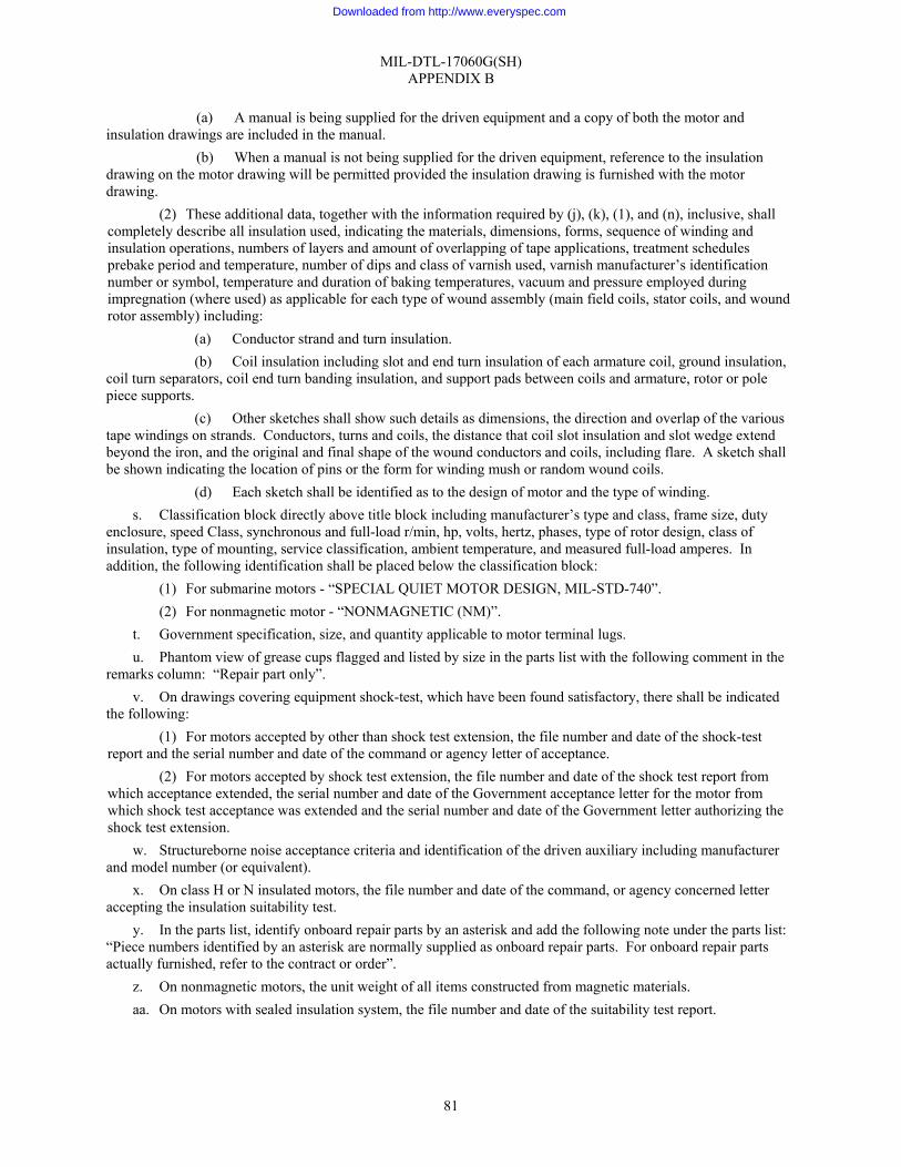
MIL-DTL-17060G(SH) APPENDIX B
81
(a) A manual is being supplied for the driven equipment and a copy of both the motor and insulation drawings are included in the manual.
(b) When a manual is not being supplied for the driven equipment, reference to the insulation drawing on the motor drawing will be permitted provided the insulation drawing is furnished with the motor drawing.
(2) These additional data, together with the information required by (j), (k), (1), and (n), inclusive, shall completely describe all insulation used, indicating the materials, dimensions, forms, sequence of winding and insulation operations, numbers of layers and amount of overlapping of tape applications, treatment schedules prebake period and temperature, number of dips and class of varnish used, varnish manufacturer’s identification number or symbol, temperature and duration of baking temperatures, vacuum and pressure employed during impregnation (where used) as applicable for each type of wound assembly (main field coils, stator coils, and wound rotor assembly) including:
(a) Conductor strand and turn insulation. (b) Coil insulation including slot and end turn insulation of each armature coil, ground insulation,
coil turn separators, coil end turn banding insulation, and support pads between coils and armature, rotor or pole piece supports.
(c) Other sketches shall show such details as dimensions, the direction and overlap of the various tape windings on strands. Conductors, turns and coils, the distance that coil slot insulation and slot wedge extend beyond the iron, and the original and final shape of the wound conductors and coils, including flare. A sketch shall be shown indicating the location of pins or the form for winding mush or random wound coils.
(d) Each sketch shall be identified as to the design of motor and the type of winding. s. Classification block directly above title block including manufacturer’s type and class, frame size, duty
enclosure, speed Class, synchronous and full-load r/min, hp, volts, hertz, phases, type of rotor design, class of insulation, type of mounting, service classification, ambient temperature, and measured full-load amperes. In addition, the following identification shall be placed below the classification block:
(1) For submarine motors - “SPECIAL QUIET MOTOR DESIGN, MIL-STD-740”. (2) For nonmagnetic motor - “NONMAGNETIC (NM)”.
t. Government specification, size, and quantity applicable to motor terminal lugs. u. Phantom view of grease cups flagged and listed by size in the parts list with the following comment in the
remarks column: “Repair part only”. v. On drawings covering equipment shock-test, which have been found satisfactory, there shall be indicated
the following: (1) For motors accepted by other than shock test extension, the file number and date of the shock-test
report and the serial number and date of the command or agency letter of acceptance. (2) For motors accepted by shock test extension, the file number and date of the shock test report from
which acceptance extended, the serial number and date of the Government acceptance letter for the motor from which shock test acceptance was extended and the serial number and date of the Government letter authorizing the shock test extension.
w. Structureborne noise acceptance criteria and identification of the driven auxiliary including manufacturer and model number (or equivalent).
x. On class H or N insulated motors, the file number and date of the command, or agency concerned letter accepting the insulation suitability test.
y. In the parts list, identify onboard repair parts by an asterisk and add the following note under the parts list: “Piece numbers identified by an asterisk are normally supplied as onboard repair parts. For onboard repair parts actually furnished, refer to the contract or order”.
z. On nonmagnetic motors, the unit weight of all items constructed from magnetic materials. aa. On motors with sealed insulation system, the file number and date of the suitability test report.
Downloaded from http://www.everyspec.com

MIL-DTL-17060G(SH) APPENDIX B
82
bb. In the specifications and exceptions block, include the number of the specification, the revision and effective date, the amendment and effective date, as applicable, and additional data pertaining to special requirements of the acquisition specifications.
NOTE: Figure 5 is indicative of the general arrangement and information desired by the command or agency concerned for a Service A motor drawing for a two-speed, integral hp, AC motor. The command or agency concerned recognizes that the information required on other designs of motors, such as single speed, will not be the same as shown hereon. In such cases, it will be permissible to add or subtract the necessary column and information so as to fit the particular motor.
cc. For mechanical fasteners in rotating assemblies, the following shall be shown: (1) Torque range for tightening. (2) Fastener that may by used in balance correction shall be identified in the parts list with the designator
“Balance.” (3) For fasteners used in balance correction, the maximum stack height of washers, including the
lockwasher, if present, that may be installed under the head of the fastener, shall be shown. The dimension shall be identified as Maximum Washer Stack Height.
dd. The method of balance correction shall be provided. ee. The serial number and date of the Government acceptance letter of the motor drawing shall be shown. ff. If used, the grade of nodular graphitic iron shall be shown in the parts list. gg. For motors with a sealed insulation system, the following note should be shown on the drawing: This is a
high reliability motor. Repair Class C overhaul, is allowable if it is in response to a conditional requirement. Winding repair shall be in accordance with NSTM Chapter 300.
hh. For submarine symmetrical motors, a note should be added to the drawing indicating that the motor is symmetrical. The procedure for interchanging the end shields, reversing the rotor assembly and rotating the frame shall be provided.
ii. For motors rated for other than continuous duty, the duty cycle or the Government document describing the duty cycle shall be shown.
jj. The following details of the bearing preload device shall be shown in the parts list, in the sectional views or in a note:
(1) The material, the outer and inner diameters and the free height shall be shown. In addition, for coiled springs, the number of coils, the coil diameter and the wire diameter shall be shown.
(2) For submarine motors with special bearing preload requirements (see 3.5.2.5.13), in addition to the information in (jj).1, above, the nominal working length and force and the plus and minus tolerance for the nominal working length and force shall be shown. The following information shall also be provided: the dimensions and tolerances of the cavity for the preload device, the surface that is machined to bring the cavity length within tolerance and the method for determining how much metal to remove from that surface to achieve the correct cavity length.
kk. Detail of the VSD motor identification plate. Information required on the plate to include the words, “VSD MOTOR”, the maximum safe rotating speed for constant torque applications, and the minimum operating speed.
ll. For motors without an applicable numeric requirement in table VI, the airborne noise acceptance criteria and the applicable contract number.
B.2.2 Drawings for service C motors. Drawings for Service C motors shall be multidetailed wherever possible. Figure 5 may be used as a guide for format and arrangement to the extent necessary to conform with the applicable data requirements. Drawings for Service C motors shall contain the following information:
a. An outline drawing showing all dimensions, clearance holes, tapped holes, holes for mounting and position of mounting.
b. Stator data including inside diameter, core length, and winding data. Winding data to include: (1) Number of poles. (2) Type of connection.
Downloaded from http://www.everyspec.com

MIL-DTL-17060G(SH) APPENDIX B
83
(3) Number of slots. (4) Number of coils. (5) Winding pitch in slots. (6) Turns in series per coil (TPC), for fractional turn windings, the sequence of TPC for a pole-phase
group shall be shown. (7) Conductor circular mils or size and form (round or rectangular). (8) Conductor insulation and Government specification. (9) Measured resistance between terminals in ohms adjusted to 77 °F (25 °C). (10) Weight of copper in pounds.
c. Rotor data including outside diameter, number of bars, bar material, and end ring size and material. d. Insulation materials and their dimensions and applicable specification of the following:
(1) Slot cell. (2) Spacer. (3) Top wedge. (4) “U” wedge (where used). (5) Insulation between phases. (6) Insulation on coil extensions. (7) Insulation on coil leads and connections. (8) Government specification and grade of varnish. (9) Lead wire size, type, and current carrying capacity.
e. A detailed working drawing of the shaft f. Schematic wiring diagram of motor windings and stator connection diagram. g. Guaranteed performance including locked-rotor current, torque and power factor; pull-up torque,
breakdown torque, and efficiency and power factor at 2⁄4, 3⁄4, and 4⁄4 load. h. Weight of complete motor in pounds. i. Classification block directly above title block including manufacturer’s type and class, frame size, duty
enclosure, speed class, synchronous and full-load r/min, hp, volts, hertz, phases, type of rotor design, class of insulation, type of mounting, service classification, ambient temperature, and measured full-load amperes. In addition, the following identification shall be placed below the classification block:
(1) For submarine motors - “SPECIAL QUIET MOTOR DESIGN, MIL-STD-740”. (2) For nonmagnetic motor - “NONMAGNETIC (NM)”.
j. Parts list for repair parts and tools (only) with manufacturer’s part numbers. k. Phantom view of grease cup, where used, with a note indicating that it is a repair part item only. l. A connection table of motor leads for two or more speed or dual voltage motors or both. Terminal
markings shall be shown on connection and wiring diagrams.
B.2.3 Drawings for motors with special preload requirements. A drawing shall be provided containing calculations demonstrating that the preload device functions as intended, as defined by the drawing details of B.3.l(jj), above, given the preload device tolerances and the tolerances on the parts that restrain them. As a minimum, the calculations shall include a tolerance stackup analysis calculating the minimum and maximum values for working length and the minimum and maximum spring force at those lengths.
Downloaded from http://www.everyspec.com

MIL-DTL-17060G(SH) APPENDIX C
84
TEST PROCEDURES FOR MOTOR EFFICIENCY
C.1. SCOPE
C.1.1 Scope. This appendix covers the efficiency testing procedures, conditions, and calculations for polyphase induction motors that are constructed to meet high efficiency requirements. This appendix is a mandatory part of the specification. The information contained herein is intended for compliance.
C.2. APPLICABLE DOCUMENTS
C.2.1 Non-Government publications. The following document forms a part of this appendix to the extent specified herein. Unless otherwise specified in the solicitation or contract, the most recent issue date of the document is applicable.
INSTITUTE OF ELECTRICAL AND ELECTRONICS ENGINEERS (IEEE)
IEEE 112 - IEEE Standard Test Procedure for Polyphase Induction Motors and Generators
(Copies of this document are available from the Institute of Electrical and Electronics Engineers, Inc., 445 Hoes Lane, P.O. Box 1331, Piscataway, NJ 08855-1331 or online at www.ieee.org.)
C.3. REQUIREMENTS
C.3.1 Motor efficiency tests. Except as specified herein, motor efficiency tests shall be performed in accordance with IEEE 112, Method B (Input-Output with Loss Segregation).
C.3.2 Order of precedence. In the event of conflict between this appendix and IEEE 112, this appendix takes precedence.
C.4. PROCEDURES
C.4.1 Test sample. The motor(s) shall be selected from normal production.
C.4.2 Test equipment. Test equipment shall be as specified in C.4.2.1 through C.4.2.4.
C.4.2.1 Digital meters. Digital meters shall be read above 15 percent of their scale range.
C.4.2.2 Analog meters. Analog meters shall be read above 50 percent of their scale range.
C.4.2.3 Accuracy. The accuracy of voltmeters and ammeters shall be at least 0.25 percent of full scale. The accuracy of wattmeters and torque meters shall be at least 0.1 percent of full scale.
C.4.2.4 Temperature measuring equipment. Temperature measuring equipment for the efficiency test shall be the same equipment used during the heat run test.
C.4.3 Measurements.
C.4.3.1 Power. The total power read on a wattmeter shall be reduced by the amount of losses in the voltage circuits of the wattmeter whenever this loss is a measurable portion of the total power read.
C.4.3.2 Slip. The accuracy of slip measurements shall be within ±5 percent of slip speed.
C.4.3.3 Temperature. Winding temperature shall be determined by the resistance method or by thermocouple (see C.4.4.2).
C.4.4 Test procedures. Test samples shall be tested as specified in C.4.4.1 through C.4.4.3.
C.4.4.1 General. Data for efficiency calculations shall be obtained from six load points, approximately equally spaced, between 25 percent and 150 percent of motor rated torque. This data shall not be obtained until temperature stabilization is attained.
Downloaded from http://www.everyspec.com

MIL-DTL-17060G(SH) APPENDIX C
85
C.4.4.2 Temperature stabilization. The efficiency test shall be conducted after the heat run test. The motor shall be operated at 100 percent of rated load until the winding temperature rise has stabilized as determined in the heat run test. Verification of achieving rated temperature rise shall be by either a rise by resistance test or by thermocouple. If verification is by thermocouple, the thermocouples shall be the same ones used in the heat run and the thermocouple installation shall be unmodified from that of the heat run test. Temperature shall be stabilized when either the rise by resistance or the rises by all thermocouples are within 37.4 °F (3 °C) of the values attained during the heat run test.
C.4.4.3 Core loss and friction and windage loss. The core loss and friction and windage loss tests shall be conducted immediately after the temperature test and at no-load.
C.4.4 Efficiency calculation. When calculating efficiency, the stator winding resistance shall be corrected to a centigrade temperature equal to the rise by resistance at 100 percent load, as determined in the heat run test, plus 77 °F (25 °C). The 77 °F (25 °C) represents a standardized ambient temperature.
Downloaded from http://www.everyspec.com

MIL-DTL-17060G(SH) APPENDIX D
86
TEST REPORT TECHNICAL CONTENT REQUIREMENTS
D.1. SCOPE
D.1.1 Scope. This appendix identifies specific content requirements pertinent to the submittal of test reports. When specified in the contract or order (see 6.2), this appendix is a mandatory part of the specification. The information contained herein is intended for compliance.
D.2. TEST REPORT CONTENT REQUIREMENTS
D.2.1 Cover and title page. The following information shall appear on the outside front cover and title page:
a. Report date. b. Report number (contractor or government). c. Contractor’s name, address, and commercial and Government entity code. d. Contract number and contract line item number or sequence number (if applicable) e. Type of test/inspection (for example, first article acceptance test, conformance inspection, developmental
test, qualification test, environmental test). f. Identification of item tested/inspected. g. Date or period of test/inspection. h. Name and address of requiring Government activity. i. Security classification, downgrading and declassifying information, if applicable.
D.2.2 First article inspection report. The report shall contain results of the first article tests/inspections of table XVIII as follows:
a. When specified, the material test (see 4.6.1) shall be performed to verify compliance of contractor selected material(s) with the minimum requirements of this specification. Test data shall be provided that compares each material characteristic identified for the minimum material requirement(s) of this specification with those of the selected material.
b. The results of the assembly inspection (see 4.6.2) shall be forwarded. Each item of the inspection shall be addressed.
c. The resistance between each pair of motor leads and the ambient temperature shall be furnished (see 4.6.3).
d. Observed results of the lubrication system shall be shown (see 4.6.4). e. The measured airborne noise levels shall be shown for each specified octave band (see 4.6.5.1). f. The measured structureborne noise levels shall be shown for each specified octave band (see 4.6.5.2). g. The maximum amplitude of vibration and the motor speed at which the vibration was measured shall be
shown (see 4.6.6). h. The bearing end play shall be shown (see 4.6.7). i. Results of the enclosure effectiveness test addressing all acceptance criteria shall be shown (see 4.6.8). j. No-load input data shall consist of the amount of operating time prior to the measurements, input watts,
speed and line volts and amperes for each phase (see 4.6.10). k. Locked-rotor data shall consist of current, watts, voltage and torque at locked-rotor, pull-up, and
breakdown. The KVA limits of the test facility shall be shown. For testing at reduced voltage, all measured and calculated data shall be shown (see 4.6.11).
l. Load test data shall consist of percent rated load, speed, watts, amps, efficiency, and power factor at 0, 25, 50, 75, 100, and 125 percent of rated load (see 4.6.12).
m. The phase characteristic test for synchronous motors shall contain measurements of field and armature current sufficient to plot a “vee” curve (see 4.6.13).
Downloaded from http://www.everyspec.com

MIL-DTL-17060G(SH) APPENDIX D
87
n. For each of the test positions of inclination, the maximum mechanical imbalance during operation and the speed shall be shown. The mechanical imbalance when mounted in its normal position (horizontal or vertical) shall be shown. A qualitative statement addressing the adequacy of the lubrication and other issues, identified in the inclined operation test requirement, shall be included (see 4.6.14).
o. The heat-run test data shall consist of the line voltage and current, watts, torque, and speed immediately before shut-down, elapsed time at the test load, the cold resistance, the cold ambient temperature, the hot resistance, the hot ambient temperature and the temperature rise. The temperature rise of each bearing, as measured on the outer ring, shall also be shown (see 4.6.16).
p. The dielectric test shall consist of the test voltage and the elapsed time of application. The report shall also indicate whether the motor withstood the proof voltage (see 4.6.17).
q. The electrical balance data shall consist of each line current as measured immediately before shut-down of the heat run and the associated percent current balance (see 4.6.18).
r. The sealed insulation system electrical test data shall consist of the test water’s conductivity and surface tension and values of insulation resistance, corrected to 77 °F (25 °C), after 1 minute, 10 minutes, 1 hour, and 24 hours of submergence. The insulation resistance, dry, corrected to 77 °F (25 °C), shall also be shown. A qualitative indication shall be included addressing the outcome of the surge test (see 4.6.19.2).
s. The efficiency test data shall consist of line current and volts, watts, speed, torque, and efficiency (see 4.6.20).
t. The preload device test data shall consist of the uncompressed length of the preload device before and after full compression. The nominal design value of compression and the force measured to achieve that compression shall also be shown (see 4.6.21).
u. The inspection of packaging test data shall consist of a qualitative evaluation of the sample packages.
D.2.3 Periodic inspection report. The report shall contain results of the periodic tests/inspections as specified in table XVIII as follows:
a. The test/inspection data shall be as specified in D.2.2, above, with the exception that the data requirement of D.2.2 (i) is not required.
D.2.4 Conformance inspection report. The report shall contain results of the periodic tests/inspections as specified in table XIX as follows:
a. The test/inspection data shall be as specified above for D.2.2(a) through (d), D.2.2(f) through (h), D.2.2(j), D.2.2 m), D.2.2(p), D.2.2(r) and D.2.2(t).
D.2.5 Shock test extension report. The report shall contain the following:
a. The drawing of the motor from which shock test acceptance is being extended. b. The drawing of the motor to which shock test acceptance is being extended. c. A copy of the shock test and motor post shock inspection associated with the motor from which shock test
acceptance is being extended. d. If extension is requested based on a Type A shock test, adequate detail of both auxiliaries should be
included to allow the determination of their similarity. D.2.6 Summary. The report shall include a summary that contains the following information: a. A brief discussion of the significant test/inspection results, observations, conclusions, and
recommendations covered in greater detail elsewhere in the report. b. Proposed corrective actions and schedules for failures or problems encountered. c. Identification of deviations, departures, or limitations encountered, referenced to the contract requirements. d. Tables, graphs, illustrations, or charts as appropriate to simplify the summary data.
Downloaded from http://www.everyspec.com

MIL-DTL-17060G(SH) APPENDIX E
88
CERTIFICATION DATA/REPORT TECHNICAL CONTENT REQUIREMENTS
E.1. SCOPE
E.1.1 Scope. This appendix covers information that shall be included in the certification/data report. When specified in the contract or order (see 6.2), this appendix is a mandatory part of the specification. The information contained herein is intended for compliance.
E.2. CERTIFICATION REPORT CONTENT REQUIREMENTS
E.2.1 Certification for sealed insulation systems. The contractor’s facility shall be certified for implementation of a sealed insulation system prior to furnishing motors to the Government. A copy of the NAVSEA letter qualifying the contractor’s facility for implementation of a sealed insulation system shall be forwarded to the Government, as specified in 4.6.19.1 of this specification, as evidence of certification.
Downloaded from http://www.everyspec.com

MIL-DTL-17060G(SH) APPENDIX F
89
SHOCK TEST REPORT TECHNICAL CONTENT REQUIREMENTS
F.1. SCOPE
F.1.1 Scope. This appendix covers information that shall be included in the shock test report. When specified in the contract or order (see 6.2), this appendix is a mandatory part of the specification. The information contained herein is intended for compliance.
F.2. SHOCK TEST REPORT TECHNICAL CONTENT REQUIREMENTS
F.2.1 General. Shock test reports shall contain the following three sections:
F.2.1.1 Test installation and conduct. This section describes the test installation, conducts, and results of the test, including applicable information of F.4. This section shall also include:
a. Description of material, size, and type of hold-down bolts (and of any other hold-down or locating devices) used to secure or locate the tested items to their foundations or test fixtures during shock tests.
b. Clear photographs of each equipment mounting configuration used during the shock test. c. A drawing of the fixture. Modifications to standard fixtures may be submitted as marked-up drawings. d. If shock test instrumentation is employed, a description of such instrumentation and a clear copy of data
recorded during the test shall be submitted with the report. e. Reference to the applicable equipment military specifications or acquisition document including the
applicable revision and date of issue shall be submitted with the report.
F.2.1.2 Post-test inspection. This section describes the conduct and results of the post-test inspection including the applicable information of F.4.
F.2.1.3 Acquisition requirements. This section states the applicable ordering data specified in acquisition documents. This may be accomplished by extracting pertinent pages or sections of the purchase specifications or acquisition document and including this material as an appendix to the report. This section shall include the contractor’s recommendations for shock test acceptances of the item tested. For each item of damage (or malfunction) which occurred as a result of shock testing, the contractor shall either recommend and rationalize design modifications which the contractor believes are required to correct any deficiencies found during the test or the post-test inspection in order to achieve acceptable shock resistance, or shall illustrate that the damage or malfunction in question does not violate applicable shock test acceptance criteria. Where matters involving shock test failure were resolved with the acceptance authority proper to the submission of the test report (see 3.1.11 of MIL-S-901), a record of these agreements shall include detailed descriptions of any damage incurred during each blow or shot and, where practicable, clear photographs of each instance of damage. This section shall also describe in detail any design modifications, repairs, or adjustments made to the item during shock tests or prior to post-test functional testing, and shall provide the equipment identification information delineated in F.4.5.
F.3. SPECIFIC REQUIREMENTS
F.3.1 Specific requirements. Each piece of equipment shall be identified with the information delineated in F.4.5. Tests shall be numbered and dated.
F.3.2 Lightweight shock machine test. The following information shall be included for all lightweight shock machine tests as defined by MIL-S-901:
a. Type of test fixture as defined by MIL-S-901. (1) If using type 4C, indicate the mounting platform. (2) If using type 6E, indicate the panel number. (3) If nonstandard, provide photographs.
b. Total weight on anvil plate. c. Instrumentation.
(1) Gauge type
Downloaded from http://www.everyspec.com
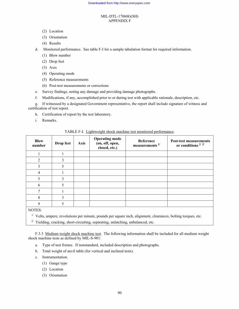
MIL-DTL-17060G(SH) APPENDIX F
90
(2) Location (3) Orientation (4) Results
d. Monitored performance. See table F-I for a sample tabulation format for required information. (1) Blow number (2) Drop feet (3) Axis (4) Operating mode (5) Reference measurements (6) Post-test measurements or corrections
e. Survey findings, noting any damage and providing damage photographs. f. Modifications, if any, accomplished prior to or during test with applicable rationale, description, etc. g. If witnessed by a designated Government representative, the report shall include signature of witness and
certification of test report. h. Certification of report by the test laboratory. i. Remarks.
TABLE F-I. Lightweight shock machine test monitored performance.
Blow number Drop feet Axis
Operating mode (on, off, open, closed, etc.)
Reference measurements 1/
Post-test measurements or conditions 1/ 2/
1 1 2 3 3 5 4 1 5 3 6 5 7 1 8 3 9 5
NOTES: 1/ Volts, ampere, revolutions per minute, pounds per square inch, alignment, clearances, bolting torques, etc. 2/ Yielding, cracking, short-circuiting, separating, unlatching, unbalanced, etc.
F.3.3 Medium weight shock machine test. The following information shall be included for all medium weight
shock machine tests as defined by MIL-S-901:
a. Type of test fixture. If nonstandard, included description and photographs. b. Total weight of anvil table (for vertical and inclined tests). c. Instrumentation.
(1) Gauge type (2) Location (3) Orientation
Downloaded from http://www.everyspec.com

MIL-DTL-17060G(SH) APPENDIX F
91
(4) Results d. Monitored performance. See table F-II for a sample tabulation format for required information.
(1) Blow number (2) Drop feet (3) Axis (4) Operating mode (5) Reference measurements (6) Post-test measurements or corrections
e. Survey findings, noting any damage and providing damage photographs. f. Modifications, if any, accomplished prior to or during test with applicable rationale, description, etc. g. Remarks. h. If witnessed by a designated Government representative, the report shall include signature of witness and
certification of test report. i. Certification of report by the test laboratory.
TABLE F-II. Medium shock machine test monitored performance.
Blow numbe
r
Group number Drop feet Axis
Operating mode (on, off, open, closed, etc.)
Reference measurements
1/
Post-test measurements or
conditions 1/ 2/ 1 I Vertical 2 II Vertical 3 III Vertical 4 I Inclined 3/ 5 II Inclined 3/ 6 III Inclined 3/
NOTES: 1/ Volts, ampere, revolutions per minute, pounds per square inch, alignment, clearances, bolting torques, etc. 2/ Yielding, cracking, short-circuiting, separating, unlatching, unbalanced, etc. 3/ Provide angle of inclination.
F.3.4 Heavyweight shock test on a floating shock platform (FSP) or large floating shock platform (LFSP). The
following information shall be included for all FSP and LFSP tests as defined by MIL-S-901:
a. Test platform as defined by MIL-S-901. b. Test fixture description including details of the installations. Photographs or sketches of the foundation and
installation. c. Total weight on the platform. d. Instrumentation.
(1) Gauge type (2) Location (3) Orientation (4) Results
e. Monitored performance. See table F-III for a sample tabulation format for required information.
Downloaded from http://www.everyspec.com

MIL-DTL-17060G(SH) APPENDIX F
92
(1) Shot number (2) Range (3) Operating mode (4) Reference measurements (5) Post-test measurements or conditions
f. Survey findings, noting any damage and providing damage photographs. g. Modifications, if any, accomplished prior to or during test with applicable rationale, description, etc. h. Remarks. i. Certification signature by test laboratory and witness and certification signature by Government activity as
to correctness of report.
TABLE F-III. Heavyweight shock machine test monitored performance.
Range Shot no.
FSP LFSP Operating mode (on, off, open, closed, etc.)
Reference measurements1/
Post-test measurements 1/ or
conditions 2/ 1 40 110 2 30 80 3 25 65 4 20 50
NOTES: 1/ Volts, amperes, revolutions per minutes, pounds per square inch, alignment, clearances, bolting torques, etc. 2/ Yielding, cracking, short-circuiting, separating, unlatching, unbalanced, etc.
F.3.5 Post-shock test – testing and inspection. The following information shall be included for all tests:
a. Identification of item being inspected through the use of such information as component name, manufacturer, and drawing number.
b. Type of shock test performed. (1) Machine (2) Platform
c. Inspection and functional tests. Type of test accomplished and approval by the appropriate inspectors. d. Repairs which were necessary during tests. e. Condition of item being tested/inspected.
(1) Breakage (2) Deformation (3) Misalignment (4) Unbalance (5) Yielding (6) Cracks (7) Momentary malfunction
f. Disposition of unit. g. Signatures certifying the report as correct.
(1) Test laboratory
Downloaded from http://www.everyspec.com

MIL-DTL-17060G(SH) APPENDIX F
93
(2) Contractor (3) Government representative
F.3.6 Equipment identification and test installation requirements. The following information shall be included for all tests:
a. Item. (1) Name (2) Type (3) Nomenclature (4) Rating (5) Service (6) Military specification and technical manual number.
b. Manufacturer (name and address). c. Model number and serial number. d. Size or capacity (if applicable). e. Plan number (sectional assembly and outline; revision and date). f. Approximate overall size of equipment.
(1) Length (2) Height (3) Width (4) Diameter
g. Weight (wet, dry, and total weight, including test fixture, wet and dry). h. Height of center-of-gravity above base of equipment. i. Contract or purchase order number. j. Requirements of MIL-S-901.
(1) Test category (2) Grade (3) Equipment class (4) Shock test type (5) Mounting location
k. Mounting aboard ship represented during shock test. (1) Plane (2) Orientation
l. Hold-down fasteners or locating devices used for attachment of items to their foundation or test fixture during shock tests.
(1) Grade (2) Size (3) Material (4) Specifications
m. Hold-down bolt torque. n. Description of resilient mounts, if used.
(1) Size (2) Type
Downloaded from http://www.everyspec.com

MIL-DTL-17060G(SH) APPENDIX F
94
(3) Location (4) Specification
o. Major components and attached items in test. p. Test laboratory and address.
F.4. FORMAT REQUIREMENTS
F.4.1 Format requirements. The shock test report shall be typed in the contractor’s format on 8½- by 11-inch paper (metric size A4).
Downloaded from http://www.everyspec.com

MIL-DTL-17060G(SH) APPENDIX G
95
EQUIPMENT AIRBORNE AND STRUCTUREBORNE NOISE MEASUREMENTS TEST REPORT TECHNICAL CONTENT REQUIREMENTS
G.1. SCOPE
G.1.1 Scope. This appendix covers information that shall be included in the equipment airborne and structureborne noise measurements test report. When specified in the contract or order (see 6.2), this appendix is a mandatory part of the specification. The information contained herein is intended for compliance.
G.2. EQUIPMENT AIRBORNE AND STRUCTUREBORNE MEASUREMENTS TEST REPORT TECHNICAL CONTENT REQUIREMENTS
G.2.1 General report requirements. Unless otherwise indicated, airborne and structureborne noise reports shall contain the following information:
G.2.1.1 Test and equipment information.
a. Equipment beings evaluated, including contract number. b. Ship names and hull number, if known, for which the unit is being acquired. c. Evaluation measurements being performed. d. Evaluating activity and test site. e. Test date. f. Data analysis date. g. Equipment specification acceptance criteria. h. Driven and driver unit manufacturers and serial numbers. i. Drive unit horsepower (hp). j. Rated electrical characteristics, including volts, amps, phase. k. Rated fluid media parameters (flow rates, temperatures, pressures, etc.). l. Equipment rated operational speeds (driver and driven unit revolutions per minute (r/min), etc.). m. Equipment noise and vibration source and their frequencies of excitation (rotationals, gear tooth contact,
blade rate, etc.). n. Resilient mount manufacturer and model number. o. Dates of resilient mount manufacture. p. Number of resilient mounts used. q. If the use of non-Navy standard resilient mounts has been approved, provide mount characteristics
including load rating in pounds, and resonant frequency data. r. Equipment load during test (full, half, etc.). s. Operating speeds during test. t. Throttling conditions, if any. u. Operating suction and discharge fluid media parameters during test (flow rates, pressures, and
temperatures, etc.). v. Electrical inputs, outputs, or both during test. w. Block diagrams and identification of make, model, and serial numbers of measurement and analysis
instrumentation used. x. Block diagrams and identification of make, model, and serial numbers of system calibration
instrumentation used. y. Place and date of latest laboratory calibration of measurement instruments, system calibrations instruments
(including field calibrators), and analysis instruments.
Downloaded from http://www.everyspec.com

MIL-DTL-17060G(SH) APPENDIX G
96
G.2.1.2 Drawings and sketches to show assembly information, equipment details, and the last set up.
a. Overall unit dimension and orientation. b. Identification of major components. c. Interface information. d. Mounting locations and dimensions. e. Weights and center of gravity for major components. f. Resilient mount orientation (vertical, horizontal, angle), approximate load on each mount, attachment
locations; overall unit weights and center of gravity. g. Pedestal or subbase dimensions, materials and weight, when applicable. h. Dimensions, materials, and weight of the mounting fixture if a mounting fixture other than the standard
fixture is used. i. Arrangement and description of flexible pipes and ducts, if used. j. Arrangement of test piping and fittings. k. Arrangement of electrical power leads. l. Location and description of test instrumentation used to measure r/min, flow rates, total discharge head, etc. m. Locations of resilient mounts and pedestals or fixtures that support the equipment.
G.2.1.2.1 Drawings and sketches to show assembly information, equipment details, and the last set up for airborne noise reports.
a. Locations and orientation of each microphone relative to equipment features. b. Locations of equipment air inlet and discharge openings. c. Description of acoustical center of sound source, assumed or measured. d. Acoustical environment (indoor).
(1) Description of location and orientation of test unit relative to floor, walls, ceiling, and contents of test room.
(2) Description of test location (anechoic, reverberant, etc.), dimensions of the test room or chamber description of the physical treatment on walls, ceiling, and floor.
e. Acoustical environment (outdoor). (1) Description of location and orientation of test unit relative to buildings, structures, or other reflecting
surfaces or objects. (2) Description of the ground surface, and wind direction and speed.
G.2.1.2.2 Drawings and sketches to show assembly information, equipment details, and the last set up for structureborne noise reports.
a. Exact location and orientation of reach accelerometer relative to equipment features or mounts, serial number of accelerometer, by location, and method of attachment of accelerometers.
G.2.1.3 Test data for airborne noise report.
a. Tabular or graphic records of the A weights levels, C weighted levels, octave band levels, and peak A-weighted sound levels required to be measured in accordance with MIL-STD-740-1. Both corrected and uncorrected data, along with all correction factors, etc., needed to obtain absolute levels to compare to specification limits.
b. Tabulation of measured levels exceeding specifications and the corresponding specification level.
G.2.1.4. Test data for structureborne noise report.
Downloaded from http://www.everyspec.com

MIL-DTL-17060G(SH) APPENDIX G
97
a. Tabular or graphic records of all acceleration levels required to be measured (including background noise) in accordance with the required measurements listed in MIL-STD-740-2. Both corrected and uncorrected data, along with all correction factors, etc., needed to obtain absolute levels to compare to specification limits.
G.3. REPORTING STANDARDS FOR STRUCTUREBORNE NOISE REPORT
G.3.1 Reporting standards. The report shall comply with the reporting standard referenced in MIL-STD-740-2.
Downloaded from http://www.everyspec.com

MIL-DTL-17060G(SH) APPENDIX H
98
INSPECTION AND TEST PLAN TECHNICAL CONTENT REQUIREMENTS
H.1. SCOPE
H.1.1 Scope. This appendix covers information regarding the format and content preparation for the inspection and test plan. When specified in the contract or order (see 6.2), this appendix is a mandatory part of the specification. The information contained herein is intended for compliance.
H.2. INSPECTION AND TEST PLAN TECHNICAL CONTENT REQUIREMENTS
H.2.1 Content. The plan shall contain a description of the inspection system, the responsibility and authority of each functional element plus other documentation prepared to implement the inspection program, including:
a. Control of source inspection, subcontractor inspection, and all incoming supplies and services. b. Training and indoctrination to assure that personnel have skills required for assuring product quality. c. Control of special environments, processes, calibrations, materials, work flow, and functional areas to
achieve program objectives. d. Control and documentation evaluations, product quality audits, instructions, special instructions, reports,
and accept-reject criteria. e. Control and inspection of parts, assemblies, nonconforming material, tolerance limits tests, and test
equipment.
H.3. POLICIES
H.3.1 Policies. The plan shall define policies which are necessary to comply with the inspection requirements and provisions of the contract and applicable specification.
H.4. FLOWCHARTS
H.4.1 Flowcharts. Flow charts shall be included to show flow of materials and identify test and inspections from receipt through all manufacturing processes, tests, and inspections to final shipment. References shall be shown to identify processes and inspection procedures, and to differentiate between in plat inspection and subcontracted inspections of subassemblies and assemblies.
Downloaded from http://www.everyspec.com

MIL-DTL-17060G(SH) INDEX
99
A aluminum frames and end shields, 11 ambient temperature, 7, 14, 15, 35, 36, 42, 44, 49, 50, 80,
81, 83, 85, 86, 87 armature and coil banding, 10
B bearing housing, 11, 12, 15, 21, 23, 25, 44, 74, 76, 77, 78 bearing mounting, 19, 21, 78 bearing preload washer or spring, 12 bearing, ball, 11, 12, 16, 17, 19, 21, 23, 24, 25, 40, 42, 44,
46, 48, 74 bearing, sleeve, 12, 18, 22, 40, 42, 43, 44, 46, 52, 80 bearings, 2, 3, 4, 5, 6, 7, 10, 11, 12, 15, 19, 20, 21, 22, 23,
24, 25, 26, 36, 43, 44, 46, 47, 51, 52, 53, 54, 73, 74, 75, 76, 77, 78, 80, 82, 86, 87
brazing alloy, 18 breakdown torque, 28, 29, 33, 34, 40, 44, 54, 55, 56, 79, 83
C cable connector, 13, 23 caution plate, 12, 25, 26 coilhead dimension and forming, 19 collector ring, 17, 73 core material, 19
D dielectric strength, 37, 40, 42, 47, 48 direction of rotation, 15
E efficiency, 15, 37, 38, 41, 50, 55, 56, 79, 80, 83, 84, 85, 86,
87 electrical balance, 37, 40, 50, 87 enclosures, 8, 11, 15, 23, 24, 27, 31, 32, 36, 38, 52, 55 end play, 12, 19, 21, 23, 40, 42, 44, 78, 86 end shield, 10, 11, 12, 13, 17, 21, 23, 24, 25, 44, 52, 74, 76,
78, 82
F fans, method of attaching to shaft, 22 feet, 10, 24, 47, 53, 76, 80, 90, 91 field coil, 10, 15, 79, 81 field connection, 13
H horsepower rating, 26, 27, 31, 49 housing construction, 12
I identification plate, 14, 15, 26, 52, 76, 80, 82 inclination, 46, 87, 91 insulation, 4, 6, 10, 13, 14, 15, 17, 19, 36, 39, 47, 48, 49,
50, 51, 52, 53, 55, 56, 73, 75, 78, 79, 80, 81, 83, 87, 88 interchangeability, 15, 25, 42 inverter duty insulation system, 51, 55
L lifting mean, 14, 76, 78 locked-rotor current, 28, 31, 32, 33, 34, 44, 45, 53, 55, 56,
79, 80, 83 locked-rotor torque, 28, 29, 30, 31, 33, 34, 44, 45, 55 lubrication, 11, 12, 15, 21, 22, 23, 25, 26, 35, 40, 42, 43,
46, 57, 77, 86, 87
M magnet wire, 23 materials, 6, 9, 10, 14, 16, 24, 39, 42, 56, 58, 73, 75, 77, 78,
79, 81, 83, 96, 98 measuring speed, provision for, 15 mechanical balance, 9, 23, 35, 40, 42, 43, 46 motor requirements, 53 motor requirements, low noise application, 27 motor requirements, nonmagnetic, 16, 24, 52, 81, 83 motor requirements, service A, 1, 7, 16, 17, 18, 23, 24, 25,
26, 40, 42, 47, 73, 78, 82 motor requirements, service C, 1, 7, 23, 26, 40, 42, 47, 48,
52, 82 motor requirements, submarine service, 27 mounting, 10, 21, 24, 26, 43, 47, 48, 52, 76, 77, 78, 81, 82,
83, 89, 93, 96
N noise, airborne, 27, 43, 47, 53, 74, 80, 82, 86, 96 noise, structureborne, 9, 27, 42, 43, 53, 55, 80, 81, 86, 95,
96
P painting, 14, 24 pull-up torque, 28, 33, 34, 40, 55, 56, 79, 83
R reliability, 3, 6, 57, 82 rotor winding, 19
S sealed insulation system, 14, 15, 16, 17, 23, 39, 41, 42, 50,
52, 53, 56, 81, 82, 87, 88 seals, 8, 11, 18, 21, 37, 52, 56, 75, 76, 77, 79, 80 securing terminal leads, 13, 22
Downloaded from http://www.everyspec.com

MIL-DTL-17060G(SH) INDEX
100
shaft, 8, 11, 12, 15, 18, 20, 21, 22, 23, 37, 43, 44, 46, 47, 48, 52, 56, 73, 74, 76, 77, 78, 79, 83
shock, 1, 3, 12, 16, 23, 40, 47, 48, 53, 54, 79, 81, 87, 89, 90, 91, 92, 93, 94
slip, 23, 28, 31, 33, 34, 50, 53, 56, 75, 84 speed, 8, 9, 10, 15, 19, 21, 22, 23, 26, 27, 28, 31, 33, 34,
35, 36, 37, 38, 43, 44, 46, 47, 49, 50, 51, 52, 54, 55, 56, 57, 78, 79, 80, 81, 82, 83, 84, 86, 87, 96
synchronous motor, 10, 16, 34, 35, 40, 42, 46, 55, 56, 57, 86
T temperature limits, 49 temporary air filter, 23, 49, 52 terminal boxes, 13, 14, 18, 24, 26, 38, 51, 76, 78
thread cutting screws, 22 threads, 1, 9, 10, 13, 22
V varnish, 14, 18, 73, 74, 75, 79, 81, 83 voltage and frequency, 7, 28, 29, 30, 31, 39, 43, 44, 46, 47,
48, 54, 55, 80
W weight, 9, 11, 28, 40, 43, 44, 47, 53, 79, 80, 81, 83, 89, 90,
91, 93, 96 windings, 7, 10, 13, 14, 15, 18, 26, 31, 36, 37, 43, 49, 50, 56, 75, 78, 79, 81, 83
Downloaded from http://www.everyspec.com

MIL-DTL-17060G(SH)
101
Preparing Activity: Navy – SH (Project 6105-2007-001) NOTE: The activities listed above were interested in this document as of the date of this document. Since organizations and responsibilities can change, you should verify the currency of the information above using the ASSIST Online database at http://assist.daps.dla.mil.
Downloaded from http://www.everyspec.com


![[NOT MEASUREMENT SENSITIVE] SUPERSEDING MIL-P-197Heveryspec.com/MIL-SPECS/MIL-SPECS-MIL-DTL/download.php?spec=… · [not measurement sensitive] mil-dtl-197j 9 july 2000 superseding](https://img.pdfslide.net/doc/110x75/5b80c51f7f8b9af7088e17c6/not-measurement-sensitive-superseding-mil-p-not-measurement-sensitive-mil-dtl-197j.jpg)


