Embed Size (px)
Citation preview
Downtown Parking Garage Design Build Criteria Documents Winter Garden, Florida Addendum #1 15-1995.00 04-09-2015
ADDENDUM #1 009000 - 1
ADDENDUM #1
1.1 PROJECT INFORMATION
A. Project Name: Downtown Parking Garage.
B. Owner: City of Winter Garden
C. Owner Project Number: AS15-13012
D. Design Criteria Professional: Walker Parking Consultants / Engineers, Inc.
E. Design Criteria Professional’s Project Number: 15-1995.00
F. Date of Addendum: April 9, 2015
1.2 NOTICE TO BIDDERS
A. This Addendum is issued to all registered Bid Document holders pursuant to the Instructions to
Bidders and Contracting Requirements. This Addendum serves to clarify, revise, and supersede information in the Project Manual, Drawings, and other supporting documents. Portions of the Addendum affecting the Contract Documents will be incorporated into the Contract by enumeration of the Addendum in the Owner/Contractor Agreement.
B. The Bidder shall acknowledge receipt of this Addendum in the appropriate space on the Bid Form.
C. The date for receipt of bids is unchanged by this Addendum.
1.3 ATTACHMENTS
A. This Addendum includes the following attached Documents and Specification Sections:
1. Project Manual Volume I – Table of Contents – reissued 04-09-2015 2. Section 011100 – SUMMARY OF WORK – reissued 04-09-2015
B. This Addendum includes the following attached Sheets:
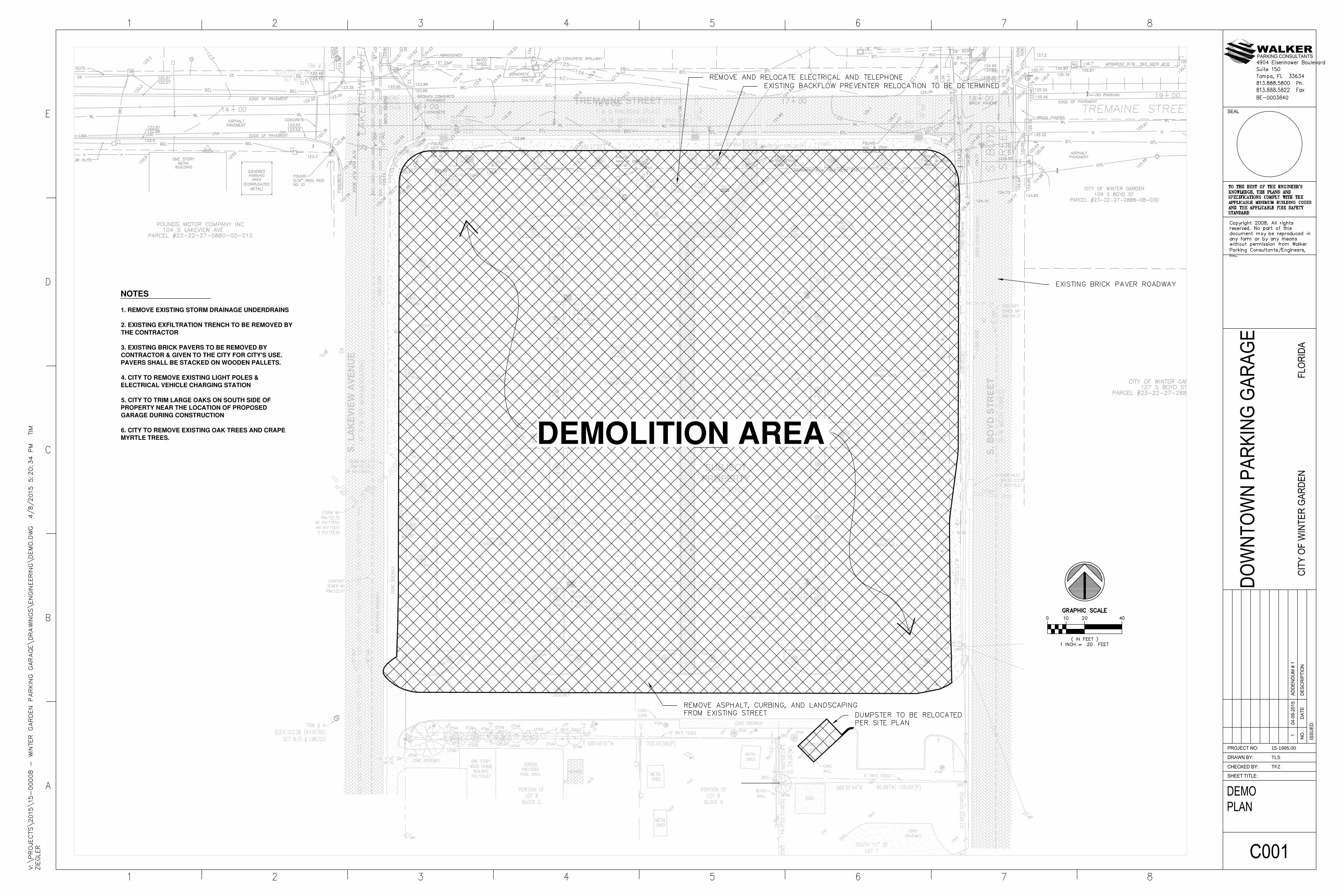
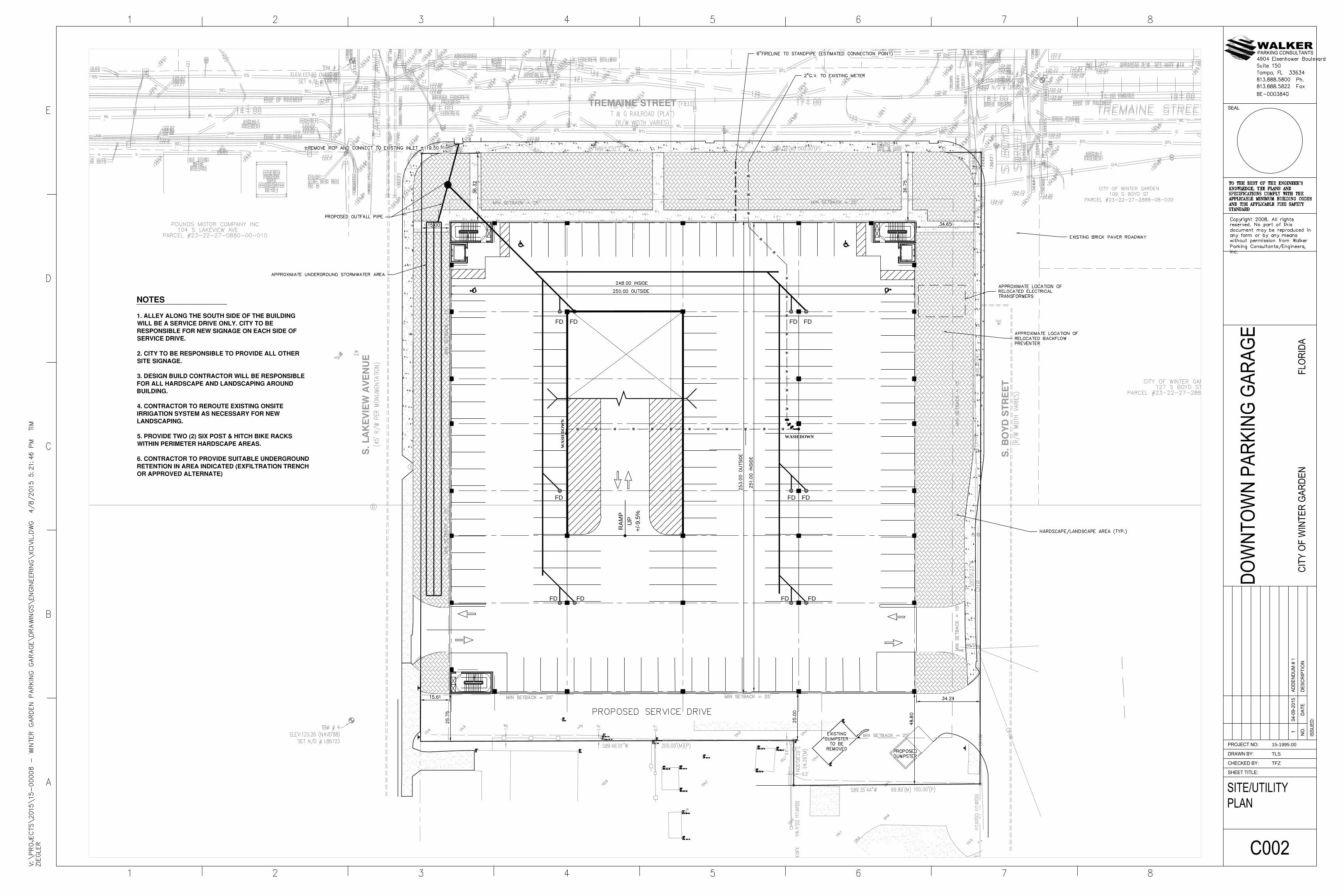
1. Demolition Plan C001 - reissued 04-09-2015 2. Site /Utility Plan C002 - reissued 04-09-2015
1.4 REVISIONS TO PROJECT MANUAL Volume I
A. Replace the Table of Contents with the attached.
Downtown Parking Garage Design Build Criteria Documents Winter Garden, Florida Addendum #1 15-1995.00 04-09-2015
ADDENDUM #1 009000 - 2
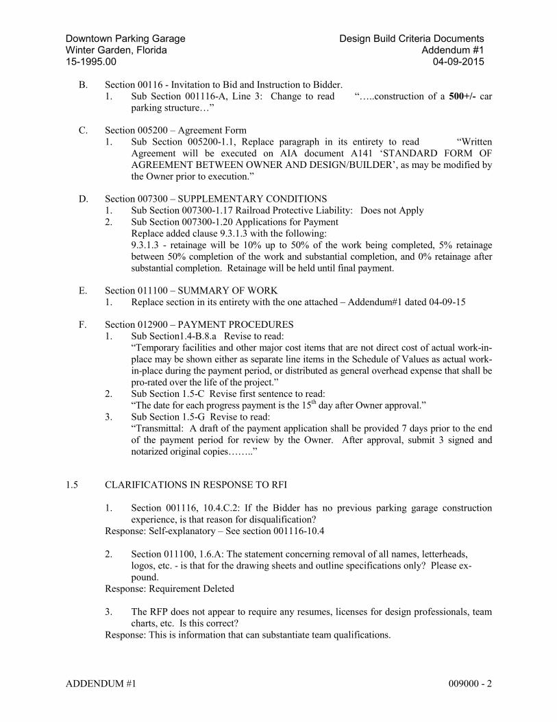
B. Section 00116 - Invitation to Bid and Instruction to Bidder. 1. Sub Section 001116-A, Line 3: Change to read “…..construction of a 500+/- car
parking structure…”
C. Section 005200 – Agreement Form 1. Sub Section 005200-1.1, Replace paragraph in its entirety to read “Written
Agreement will be executed on AIA document A141 ‘STANDARD FORM OF AGREEMENT BETWEEN OWNER AND DESIGN/BUILDER’, as may be modified by the Owner prior to execution.”
D. Section 007300 – SUPPLEMENTARY CONDITIONS 1. Sub Section 007300-1.17 Railroad Protective Liability: Does not Apply 2. Sub Section 007300-1.20 Applications for Payment
Replace added clause 9.3.1.3 with the following: 9.3.1.3 - retainage will be 10% up to 50% of the work being completed, 5% retainage between 50% completion of the work and substantial completion, and 0% retainage after substantial completion. Retainage will be held until final payment.
E. Section 011100 – SUMMARY OF WORK 1. Replace section in its entirety with the one attached – Addendum#1 dated 04-09-15
F. Section 012900 – PAYMENT PROCEDURES 1. Sub Section1.4-B.8.a Revise to read:
“Temporary facilities and other major cost items that are not direct cost of actual work-in-place may be shown either as separate line items in the Schedule of Values as actual work-in-place during the payment period, or distributed as general overhead expense that shall be pro-rated over the life of the project.”
2. Sub Section 1.5-C Revise first sentence to read: “The date for each progress payment is the 15th day after Owner approval.”
3. Sub Section 1.5-G Revise to read: “Transmittal: A draft of the payment application shall be provided 7 days prior to the end of the payment period for review by the Owner. After approval, submit 3 signed and notarized original copies……..”
1.5 CLARIFICATIONS IN RESPONSE TO RFI 1. Section 001116, 10.4.C.2: If the Bidder has no previous parking garage construction
experience, is that reason for disqualification? Response: Self-explanatory – See section 001116-10.4 2. Section 011100, 1.6.A: The statement concerning removal of all names, letterheads,
logos, etc. - is that for the drawing sheets and outline specifications only? Please ex-pound.
Response: Requirement Deleted 3. The RFP does not appear to require any resumes, licenses for design professionals, team
charts, etc. Is this correct? Response: This is information that can substantiate team qualifications.
Downtown Parking Garage Design Build Criteria Documents Winter Garden, Florida Addendum #1 15-1995.00 04-09-2015
ADDENDUM #1 009000 - 3
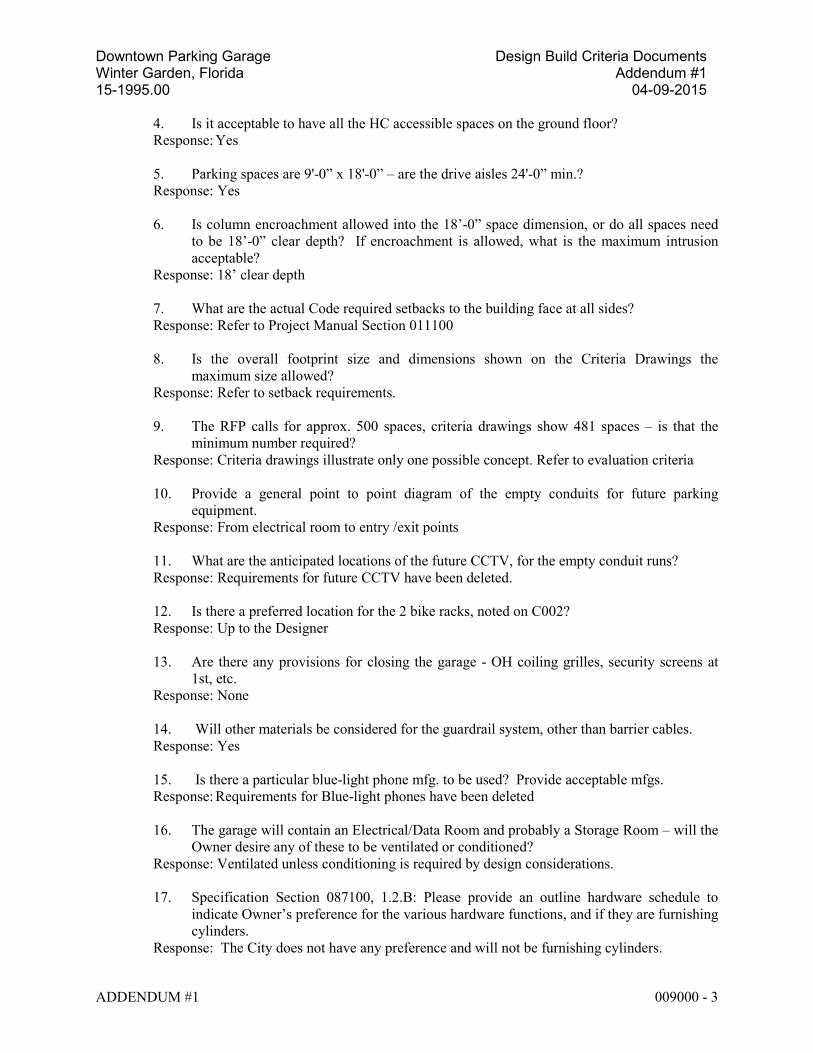
4. Is it acceptable to have all the HC accessible spaces on the ground floor? Response: Yes 5. Parking spaces are 9'-0” x 18'-0” – are the drive aisles 24'-0” min.? Response: Yes 6. Is column encroachment allowed into the 18’-0” space dimension, or do all spaces need
to be 18’-0” clear depth? If encroachment is allowed, what is the maximum intrusion acceptable?
Response: 18’ clear depth 7. What are the actual Code required setbacks to the building face at all sides? Response: Refer to Project Manual Section 011100 8. Is the overall footprint size and dimensions shown on the Criteria Drawings the
maximum size allowed? Response: Refer to setback requirements. 9. The RFP calls for approx. 500 spaces, criteria drawings show 481 spaces – is that the
minimum number required? Response: Criteria drawings illustrate only one possible concept. Refer to evaluation criteria
10. Provide a general point to point diagram of the empty conduits for future parking
equipment. Response: From electrical room to entry /exit points
11. What are the anticipated locations of the future CCTV, for the empty conduit runs? Response: Requirements for future CCTV have been deleted.
12. Is there a preferred location for the 2 bike racks, noted on C002? Response: Up to the Designer
13. Are there any provisions for closing the garage - OH coiling grilles, security screens at
1st, etc. Response: None
14. Will other materials be considered for the guardrail system, other than barrier cables. Response: Yes 15. Is there a particular blue-light phone mfg. to be used? Provide acceptable mfgs. Response: Requirements for Blue-light phones have been deleted
16. The garage will contain an Electrical/Data Room and probably a Storage Room – will the
Owner desire any of these to be ventilated or conditioned? Response: Ventilated unless conditioning is required by design considerations.
17. Specification Section 087100, 1.2.B: Please provide an outline hardware schedule to
indicate Owner’s preference for the various hardware functions, and if they are furnishing cylinders.
Response: The City does not have any preference and will not be furnishing cylinders.
Downtown Parking Garage Design Build Criteria Documents Winter Garden, Florida Addendum #1 15-1995.00 04-09-2015
ADDENDUM #1 009000 - 4
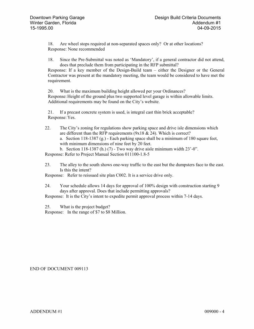
18. Are wheel stops required at non-separated spaces only? Or at other locations? Response: None recommended
18. Since the Pre-Submittal was noted as ‘Mandatory’, if a general contractor did not attend,
does that preclude them from participating in the RFP submittal? Response: If a key member of the Design-Build team – either the Designer or the General Contractor was present at the mandatory meeting, the team would be considered to have met the requirement.
20. What is the maximum building height allowed per your Ordinances? Response: Height of the ground plus two supported level garage is within allowable limits. Additional requirements may be found on the City’s website.
21. If a precast concrete system is used, is integral cast thin brick acceptable? Response: Yes.
22. The City’s zoning for regulations show parking space and drive isle dimensions which are different than the RFP requirements (9x18 & 24). Which is correct? a. Section 118-1387 (g.) - Each parking space shall be a minimum of 180 square feet, with minimum dimensions of nine feet by 20 feet. b. Section 118-1387 (h.) (7) - Two way drive aisle minimum width 23’-0”.
Response: Refer to Project Manual Section 011100-1.8-5 23. The alley to the south shows one-way traffic to the east but the dumpsters face to the east.
Is this the intent? Response: Refer to reissued site plan C002. It is a service drive only. 24. Your schedule allows 14 days for approval of 100% design with construction starting 9
days after approval. Does that include permitting approvals? Response: It is the City’s intent to expedite permit approval process within 7-14 days. 25. What is the project budget? Response: In the range of $7 to $8 Million.
END OF DOCUMENT 009113
Downtown Parking Garage Design Build Criteria Documents Winter Garden, Florida March 2015 15-1995.00
©2015, Walker Parking Consultants/Engineers, Inc. All rights reserved. TABLE OF CONTENTS 000110 - 1
SECTION 000110 – TABLE OF CONTENTS
VOLUME I
DIVISION 00 – PROCUREMENT & CONTRACTING AGREEMENTS
PROCUREMENT REQUIREMENTS
001116 Invitation to Bid & Instructions to Bidders 004100 Bid Forms
CONTRACTING REQUIREMENTS
005200-AIA Agreement Form 006113 Performance & Payment Bond 007200-AIA General Conditions 007300-AIA07 Supplementary Conditions
DIVISION 01 - GENERAL REQUIREMENTS
011100 Summary of Work 012100 Allowances 012600 Contract Modification Procedures 012900 Payment Procedures 013100 Project Management & Coordination 013200 Construction Progress Documentation 013300 Submittal Procedures 014210 Reference Standards and Definitions 014500 Quality Control 015000 Temporary Facilities and Controls 016010 Product Substitution Procedures 017300 Execution 017329 Cutting & Patching 017423 Final Cleaning 017700 Closeout Procedures 017823 Operation & Maintenance Data 017836 Warranties 017839 Project Record Documents 017900 Demonstration & Training
VOLUME II - TECHNICAL SPECIFICATIONS
DIVISION 02 – EXISTING CONDITIONS
024110 Selective Structure Demolition
Downtown Parking Garage Design Build Criteria Documents Winter Garden, Florida March 2015 15-1995.00
©2015, Walker Parking Consultants/Engineers, Inc. All rights reserved. TABLE OF CONTENTS 000110 - 2
DIVISION 03 – CONCRETE
033000 Cast-in-Place Concrete 033816 Unbonded Post-Tensioned Concrete 034100 Precast Structural Concrete
DIVISION 04 - MASONRY
042000 Unit Masonry
DIVISION 05 – METALS
051200 Structural Steel Framing 051617 Strand Guardrail System 055010 Metal Fabrications 055213 Pipe and Tube Railings
DIVISION 06 – WOOD, PLASTICS & COMPOSITES
061000 Rough Carpentry
DIVISION 07 - THERMAL AND MOISTURE PROTECTION
071800 Traffic Coatings 071900 Water Repellents 075216 SBS - Modified Bituminous Protected Membrane Roofing 076200 Sheet Metal Flashing and Trim 079233 Concrete Joint Sealants
079236 Architectural Joint Sealants 079500 Expansion Joint Assemblies
DIVISION 08 - OPENINGS
081113 Hollow Metal Doors & Frames 087100 Door Hardware
DIVISION 09 – FINISHES
099120 Pavement Marking
DIVISION 10 – SPECIALTIES
101400 Signage
DIVISION 14 - CONVEYING EQUIPMENT
14211 Electric Traction Elevators -Machine Room-Less (MRL)
Downtown Parking Garage Design Build Criteria Documents Winter Garden, Florida March 2015 15-1995.00
©2015, Walker Parking Consultants/Engineers, Inc. All rights reserved. TABLE OF CONTENTS 000110 - 3
DIVISION 22 - PLUMBING
220500 Common Work Results for Plumbing 221116 Domestic Water Piping 221413 Facility Storm Drainage Piping
DIVISION 26 - ELECTRICAL
260500 Common Work Results for Electrical 260923 Lighting Control Devices 265000 Lighting 265001 Lighting Design Performance
DIVISION 31 – EARTHWORK
311000 Site Clearing 312200 Site Grading 312319 Dewatering 312333 Excavation and Backfilling for Utilities 315000 Excavation Support & Protection 316213 Concrete Piles
DIVISION 32 – EXTERIOR IMPROVEMENTS
321000 Asphalt Paving
DIVISION 33 – UTILITIES
331000 Water Utilities 334000 Storm Drainage Utilities 334900 Storm Drainage Structures
END OF TABLE OF CONTENTS
Copyright 2015. All rights reserved. No part of this document may be reproduced in any form or by any means without permission from Walker Parking Consultants/Engineers Inc.
Downtown Parking Garage Design Build Criteria Documents Winter Garden, Florida March 2015 15-1995.00
©2015, Walker Parking Consultants/Engineers, Inc. All rights reserved. TABLE OF CONTENTS 000110 - 4
LEFT BLANK INTENTIONALLY
Downtown Parking Garage Design Build Criteria Documents Winter Garden, Florida March 2015 15-1995.00 Addendum-1 04-09-2015
©2015, Walker Parking Consultants/Engineers, Inc. All rights reserved. SUMMARY OF WORK 011100-1
SECTION 011100 - SUMMARY OF WORK
PART 1 - GENERAL
1.1 SCOPE OF WORK
A. The Work contemplated by the Contract Documents includes the Work of all trades required and all the labor, materials and equipment necessary and incidental to the design, construction and completion of:
Parking Garage City of Winter Garden Winter Garden, Florida & all associated site-work including the pedestrian plaza on the north side of the parking structure, relocation of the transformers, back-flow preventers and trash compactor.
Any requirements stated herein refer to the entire project. B. Parking Structure System Design - An integral part of this Project is the preparation of
final design drawings and specifications necessary for the fabrication and construction of all architectural, civil, structural, mechanical, fire protection and electrical components required. The Contractor will be required to employ a qualified Designer to perform such design. Such design shall meet the criteria established in these documents. It shall be the responsibility of the Designer to prepare and seal final architectural, civil, landscape/hardscape, structural, mechanical, fire protection, lightning protection and electrical design drawings and specifications, submit these drawings to the governing agencies including the Fire Marshall’s Office, City Building Department, and other applicable agencies for approval, review Shop Drawings prepared by the Contractor, and make necessary field observations to insure that the Project is being constructed in accordance with his prepared design drawings and specifications. The Design Criteria Professional (DCP) will be the Owner's technical representative for the Project and the Owner will be responsible for general Project administration. The Designer will be responsible for all design including architectural, civil, landscape/hardscape, structural, mechanical, fire protection, lightning protection and electrical design for the Project, and shall be required to submit his final drawings, specifications, and calculations for such design to the Owner and DCP for review prior to any fabrication and construction for the Project.
1.2 SITE REVIEW
A. Before submitting Proposals, prospective Design/Build Contractors shall carefully
examine the entire site of the proposed work and adjacent premises and the various means of approach and access to the site, and make all necessary investigations to inform themselves thoroughly as to all difficulties involved in the completion of all the work in accordance with the Contract Documents.
Downtown Parking Garage Design Build Criteria Documents Winter Garden, Florida March 2015 15-1995.00 Addendum-1 04-09-2015
©2015, Walker Parking Consultants/Engineers, Inc. All rights reserved. SUMMARY OF WORK 011100-2
B. The Contractor shall immediately, upon entering the project site for the purpose of beginning work, review project site with the Owner for the purpose of selecting area(s) to place materials for storage and staging.
C. The Contractor must exercise proper precaution to verify all figures shown or indicated
on the Drawings. All existing trees, paved areas; utilities, etc. shall be located before beginning any work, and he shall be held responsible for any error resulting from his failure to exercise such precaution. The Contractor shall be responsible for verification or relocation of any utilities.
1.3 WORK BY OTHERS
A. The Contractor shall allow access to the site and coordination for installation of any Owner-furnished equipment including CCTV Equipment.
1.4 FUTURE WORK
A. The parking deck will not be designed for any future expansion.
1.5 CONTRACTOR USE OF PREMISES
A. Area indicated on Construction Site Plan is set aside for Contractor's use. Any remaining area of the existing parking lot outside these limits shall not be used without written permission from the Owner. Access for all construction traffic including equipment and materials shall be coordinated with the City of Winter Garden.
1.6 DESIGN INFORMATION TO BE SUBMITTED WITH PROPOSAL
A. Each Contractor shall submit with his Proposal seven (7) sets of “design information”, along with one (1) copy in electronic format on CD/DVD, addressed to Amy Martello, Office of the City Manager, City of Winter Garden, 300 West Plant Street, Winter Garden, FL 34787. Bind or package each set separately in opaque envelopes. All documents shall be free of name, letterheads, logos or any other identifying marks to ensure anonymity. Any identifying mark or qualification on any of the submitted documents shall be considered grounds for disqualification of the bid. East Each set of “design information” shall contain the following:
1. Preliminary design drawings consisting of: Floor plans, (street level, typical level,
and top level), at 1/16” = 1’ – 0” scale showing traffic flow, parking spaces, column locations, guard rail locations, lighting layout, floor drain locations and mechanical ventilation, ramp slopes, stair and elevator locations, typical and overall dimensions. East, west, north and south elevations, at 1/16” = 1’ – 0” scale, showing façade treatment, typical and overall dimensions, and column spacing. Longitudinal and transverse through building sections, showing structural system and basic details. Perspective or other model/drawing showing
Downtown Parking Garage Design Build Criteria Documents Winter Garden, Florida March 2015 15-1995.00 Addendum-1 04-09-2015
©2015, Walker Parking Consultants/Engineers, Inc. All rights reserved. SUMMARY OF WORK 011100-3
three-dimensional view of structure from the northwest and northeast. Any other drawing or details that the Bidder may wish to submit to clarify his design.
2. “Short form” specifications conforming to the specific requirements of this Request for Proposals and descriptions to include the following: Structural, mechanical and electrical system description and components, waterproofing, exterior treatment description, any other information which may aid in evaluating the proposed design.
3. A Quality Plan describing the design and construction phase quality assurance measures.
4. Rendering or any other information that may aid in evaluating the design. 5. Estimated design and construction progress schedule, showing the proposed
dates of commencement and completion of the various subdivisions of the Work (both design and construction) and critical path. See Milestone Table for required dates.
6. A Site Mobilization plan.
1.7 SUBMISSION OF FINAL DESIGN DRAWINGS, CALCULATIONS AND
SPECIFICATIONS
A. The selected Design/Build Contractor shall submit design drawings, calculations and
specifications to the Owner and DCP at 50% and 100% completion stages for review in accordance with the Milestone Table. The final (100%) design drawings, calculations and specifications shall be submitted to the Owner and DCP for review in ample time (10 working days, minimum) to allow such review before proceeding with any fabrication or construction. Drawings shall include complete set of construction documents including landscape/hardscape, civil, architectural, structural, mechanical, electrical, plumbing, and fire protection design drawings. These Design drawings, calculations prepared and sealed by the designer, and specifications shall be complete in every detail necessary for fabrication and construction of the Project, complying with the design intent and requirements contained in this Request for Proposals. Submission in “stages” or phased construction is not acceptable.
B. All drawings, calculations and specifications prepared by the Designer shall be certified
(bear the seal and signature of an architect/engineer registered in the State of Florida) before they are submitted for review.
1.8 GENERAL DESIGN CRITERIA
A. General: See Invitation for Proposals.
B. Design Requirements:
1. General: The criteria set out in this Section of this Request for Proposals and in the Technical Specifications are the minimum acceptable design requirements, which shall apply for this project. Those submitting Proposals should review both this section and all other Technical Specification sections before preparing a Proposal. Any proposed design based on criteria which does not equal or exceed the following requirements shall be rejected.
Downtown Parking Garage Design Build Criteria Documents Winter Garden, Florida March 2015 15-1995.00 Addendum-1 04-09-2015
©2015, Walker Parking Consultants/Engineers, Inc. All rights reserved. SUMMARY OF WORK 011100-4
2. General Description:
a. This project shall consist of the design and complete construction of a permanent three (3) level (ground and two supported), open type parking structure which shall accommodate up to 500+/- parking spaces . The structure shall include concrete slab on grade and necessary supported floor slabs (top slab open) with appropriate up and down ramps.
b. The structure shall be complete with pedestrian stairs, elevators, guard rails, drainage system, striping and markings, waterproofing, exterior treatment, fire protection system, lightning protection system, lighting, empty conduits for future CCTV and audio surveillance systems, hereafter specified and as necessary to provide a complete, functional, relatively maintenance free, aesthetically pleasing structure conforming with the architectural criteria included in the Criteria Documents, conforming to applicable codes, ready for operation.
c. Stair and stair/elevator towers to have modified bituminous roofing with minimum 20-year warranty.
d. Maximum dimensions for the parking structure footprint with preferred vehicular circulation and location of alternate walkway are indicated on the plans.
3. Usage: Primary use of this structure will be to provide an “unattended" self-parking area for general public.
4. Design Capacity:
a. The Designer shall design a "permanent", open type, three (3) level parking structure which shall accommodate up to 500+/- parking spaces. In this context, "permanent" shall mean that the parking structure shall be designed and constructed to have an expected functional life of sixty (60) years, and shall be expected to perform satisfactorily during that time span.
b. At completion of construction, provide the Owner with four (4) copies of a complete maintenance manual containing a description and schedule of maintenance tasks, which will maintain a satisfactory performance level for the above-expected functional life.
5. Parking Geometrics and Traffic Flow: The parking layout and design of the traffic flow patterns shall be governed by the following requirements:
a. Minimum two entrance and two exit lanes shall be provided at the ground level as shown.
b. 90o angle parking with two-way traffic and/or 70o angle parking with one-way traffic shall be used.
c. Minimum width and length of parking spaces shall be 9’-0”x 18’- 0”. d. Ramp Slopes shall be held to a minimum throughout with smooth
transitions at both ends. Ramps without parking shall not have slopes greater than 12% and ramps with parking shall not have slopes greater than 5.9% unless indicated otherwise.
e. Buried Spaces (i.e., a space which can be blocked from ingress or egress by another space as "end to end spaces" or "corner spaces") shall not be permitted.
Downtown Parking Garage Design Build Criteria Documents Winter Garden, Florida March 2015 15-1995.00 Addendum-1 04-09-2015
©2015, Walker Parking Consultants/Engineers, Inc. All rights reserved. SUMMARY OF WORK 011100-5
f. Turning Radii shall not be less than 30' to the outside curb of an inside lane.
g. Parking Layout dimensions are shown on plans Minimum aisle width shall be 24’-0” for two-way traffic and 17’-0” for one way traffic.
h. Curbs shall be used only at entrance and exit lanes on which to place any future parking equipment. Curbs will not be permitted in any other locations except as noted on drawings.
i. Dividers shall be used to direct vehicle and pedestrian traffic. Minimum clear height under structural beams or tee stems shall be 8'-2", except it shall be 7'-2" at second level. This minimum clearance shall be maintained at all locations including at slope changes.
j. Minimum floor-to-floor heights shall be 11’-6” ground to second and 10’-6” above.
k. Schematic functional layout is included as part of the scope criteria.
6. Compliance with Americans with Disabilities Act (ADA) Guidelines: Design of the facility shall fully comply with the ADA accessibility requirements.
C. Structural Design Requirements: The following structural components, or a combination thereof, shall be used to construct the parking structure.
1. Foundation Design Criteria: Foundation design criteria are provided by the
geotechnical report for the Project. The report is part of this Request for Proposals. The Owner assumes no responsibility for the accuracy or completeness of this document. The report is provided for information only, and the designer may draw his own conclusions or conduct his own subsurface exploration as required.
2. Entire structure and individual members shall be designed considering all vertical loads, lateral loads due to wind, temperature differentials, seismic, shrinkage, shortening and effects due to prestressing (both pre-tensioning and post-tensioning). Rigid elements including, but not limited to, stair towers, elevator towers, grade and foundation structures, shall be kept structurally free of the main body of the parking structure. Any elements, which would tend to structurally restrain the main body of the parking structure shall be accounted for in the structural design.
3. All members shall have the fire ratings as stated in the latest edition of all applicable codes.
4. The temperature differential used for designing the precast and post-tensioned systems shall be based on the following criteria:
a. Post-Tensioned System: The temperature extremes (contraction and
expansion) shall be taken as the difference of the daily maximum and daily minimum with respect to the average daily temperature at the time the concrete beams and slabs are stressed. The curing temperature of the concrete must be taken into consideration. See Subsection 1.08 D for additional member design criteria.
b. Precast System: The temperature extremes (contraction and expansion) shall be taken as the difference of the daily maximum and daily minimum with respect to the average daily temperature at the time the concrete topping is placed. See Subsection 1.08 E for additional member design criteria.
Downtown Parking Garage Design Build Criteria Documents Winter Garden, Florida March 2015 15-1995.00 Addendum-1 04-09-2015
©2015, Walker Parking Consultants/Engineers, Inc. All rights reserved. SUMMARY OF WORK 011100-6
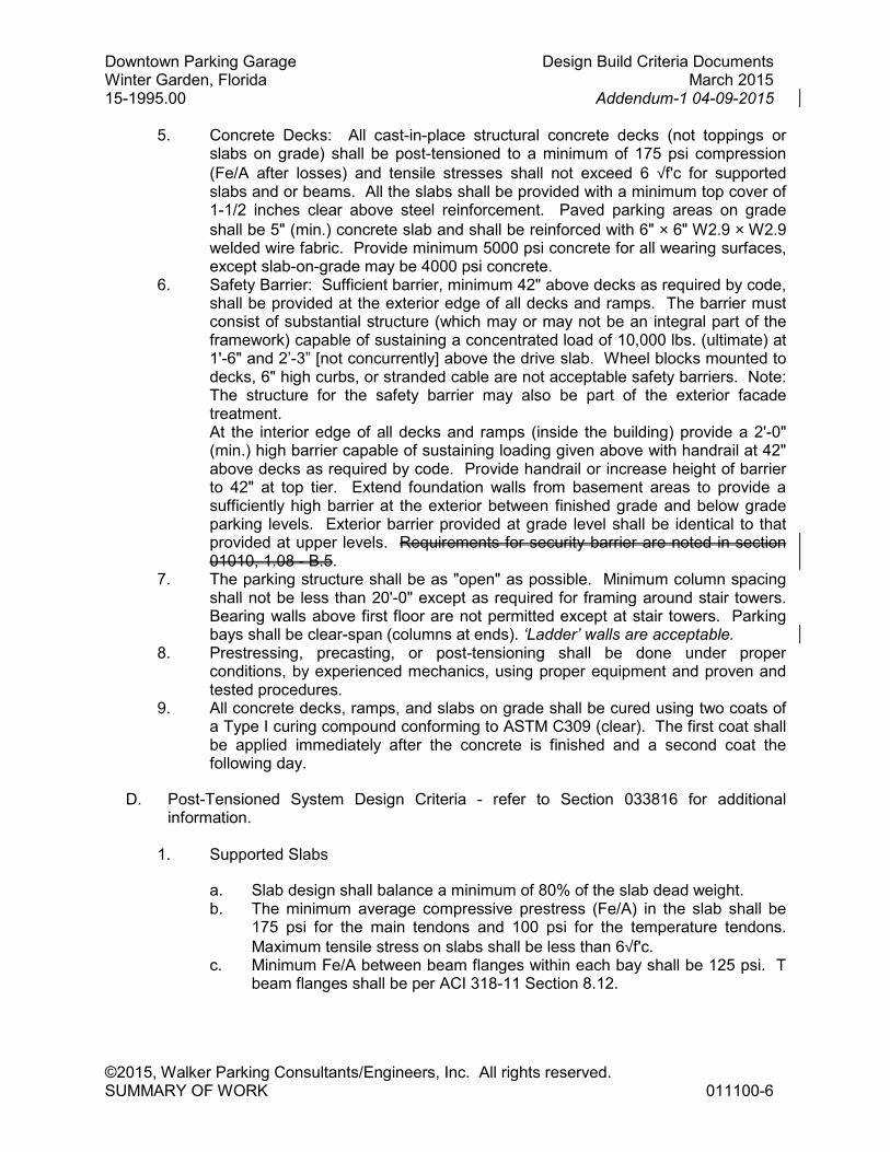
5. Concrete Decks: All cast-in-place structural concrete decks (not toppings or slabs on grade) shall be post-tensioned to a minimum of 175 psi compression
(Fe/A after losses) and tensile stresses shall not exceed 6 √f'c for supported slabs and or beams. All the slabs shall be provided with a minimum top cover of 1-1/2 inches clear above steel reinforcement. Paved parking areas on grade
shall be 5" (min.) concrete slab and shall be reinforced with 6" × 6" W2.9 × W2.9 welded wire fabric. Provide minimum 5000 psi concrete for all wearing surfaces, except slab-on-grade may be 4000 psi concrete.
6. Safety Barrier: Sufficient barrier, minimum 42" above decks as required by code, shall be provided at the exterior edge of all decks and ramps. The barrier must consist of substantial structure (which may or may not be an integral part of the framework) capable of sustaining a concentrated load of 10,000 lbs. (ultimate) at 1'-6" and 2’-3” [not concurrently] above the drive slab. Wheel blocks mounted to decks, 6" high curbs, or stranded cable are not acceptable safety barriers. Note: The structure for the safety barrier may also be part of the exterior facade treatment. At the interior edge of all decks and ramps (inside the building) provide a 2'-0" (min.) high barrier capable of sustaining loading given above with handrail at 42" above decks as required by code. Provide handrail or increase height of barrier to 42" at top tier. Extend foundation walls from basement areas to provide a sufficiently high barrier at the exterior between finished grade and below grade parking levels. Exterior barrier provided at grade level shall be identical to that provided at upper levels. Requirements for security barrier are noted in section 01010, 1.08 - B.5.
7. The parking structure shall be as "open" as possible. Minimum column spacing shall not be less than 20'-0" except as required for framing around stair towers. Bearing walls above first floor are not permitted except at stair towers. Parking bays shall be clear-span (columns at ends). ‘Ladder’ walls are acceptable.
8. Prestressing, precasting, or post-tensioning shall be done under proper conditions, by experienced mechanics, using proper equipment and proven and tested procedures.
9. All concrete decks, ramps, and slabs on grade shall be cured using two coats of a Type I curing compound conforming to ASTM C309 (clear). The first coat shall be applied immediately after the concrete is finished and a second coat the following day.
D. Post-Tensioned System Design Criteria - refer to Section 033816 for additional information.
1. Supported Slabs
a. Slab design shall balance a minimum of 80% of the slab dead weight. b. The minimum average compressive prestress (Fe/A) in the slab shall be
175 psi for the main tendons and 100 psi for the temperature tendons.
Maximum tensile stress on slabs shall be less than 6√f'c. c. Minimum Fe/A between beam flanges within each bay shall be 125 psi. T
beam flanges shall be per ACI 318-11 Section 8.12.
Downtown Parking Garage Design Build Criteria Documents Winter Garden, Florida March 2015 15-1995.00 Addendum-1 04-09-2015
©2015, Walker Parking Consultants/Engineers, Inc. All rights reserved. SUMMARY OF WORK 011100-7
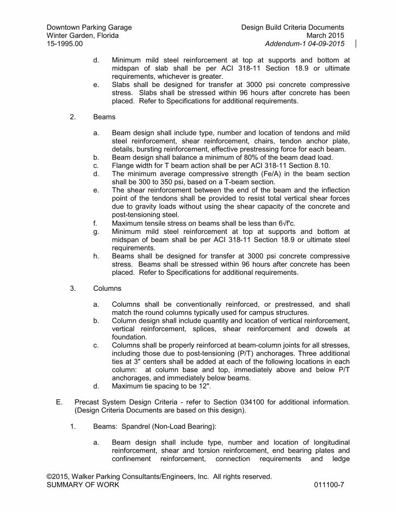
d. Minimum mild steel reinforcement at top at supports and bottom at midspan of slab shall be per ACI 318-11 Section 18.9 or ultimate requirements, whichever is greater.
e. Slabs shall be designed for transfer at 3000 psi concrete compressive stress. Slabs shall be stressed within 96 hours after concrete has been placed. Refer to Specifications for additional requirements.
2. Beams
a. Beam design shall include type, number and location of tendons and mild steel reinforcement, shear reinforcement, chairs, tendon anchor plate, details, bursting reinforcement, effective prestressing force for each beam.
b. Beam design shall balance a minimum of 80% of the beam dead load. c. Flange width for T beam action shall be per ACI 318-11 Section 8.10. d. The minimum average compressive strength (Fe/A) in the beam section
shall be 300 to 350 psi, based on a T-beam section. e. The shear reinforcement between the end of the beam and the inflection
point of the tendons shall be provided to resist total vertical shear forces due to gravity loads without using the shear capacity of the concrete and post-tensioning steel.
f. Maximum tensile stress on beams shall be less than 6√f'c. g. Minimum mild steel reinforcement at top at supports and bottom at
midspan of beam shall be per ACI 318-11 Section 18.9 or ultimate steel requirements.
h. Beams shall be designed for transfer at 3000 psi concrete compressive stress. Beams shall be stressed within 96 hours after concrete has been placed. Refer to Specifications for additional requirements.
3. Columns
a. Columns shall be conventionally reinforced, or prestressed, and shall match the round columns typically used for campus structures.
b. Column design shall include quantity and location of vertical reinforcement, vertical reinforcement, splices, shear reinforcement and dowels at foundation.
c. Columns shall be properly reinforced at beam-column joints for all stresses, including those due to post-tensioning (P/T) anchorages. Three additional ties at 3" centers shall be added at each of the following locations in each column: at column base and top, immediately above and below P/T anchorages, and immediately below beams.
d. Maximum tie spacing to be 12".
E. Precast System Design Criteria - refer to Section 034100 for additional information. (Design Criteria Documents are based on this design).
1. Beams: Spandrel (Non-Load Bearing):
a. Beam design shall include type, number and location of longitudinal reinforcement, shear and torsion reinforcement, end bearing plates and confinement reinforcement, connection requirements and ledge
Downtown Parking Garage Design Build Criteria Documents Winter Garden, Florida March 2015 15-1995.00 Addendum-1 04-09-2015
©2015, Walker Parking Consultants/Engineers, Inc. All rights reserved. SUMMARY OF WORK 011100-8
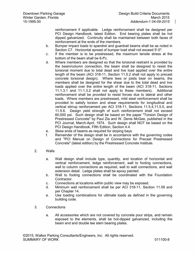
reinforcement if applicable. Ledge reinforcement shall be designed per PCI Design Handbook, latest Edition. End bearing plates shall be hot dipped galvanized. Continuity shall be maintained between both faces of reinforcement at the ends of the members.
b. Bumper impact loads to spandrel and guardrail beams shall be as noted in Section C7. Horizontal spread of bumper load shall not exceed 5'-0".
c. If the member is to be prestressed, the maximum tensile stress at the
bottom of the beam shall be 6√f'c. d. Where members are designed so that the torsional restraint is provided by
the beam/column connection, the beam shall be designed to resist the torsional moment due to total dead and live load applied over the entire length of the beam (ACI 318-11, Section 11.5.2 shall not apply to precast concrete torsional design). Where tees or joists bear on beams, the members shall be designed for the shear due to the total dead and live loads applied over the entire length of the beam (ACI 318-11, Sections 11.1.3.1 and 11.1.3.2 shall not apply to these members). Additional reinforcement shall be provided to resist forces due to lateral and other loads. Where members are prestressed, mild steel reinforcement shall be provided to satisfy torsion and shear requirements for longitudinal and vertical stirrup reinforcement per ACI 318-11, Sections 11.5.4,11.5.5, and 11.5.6. Design yield strength of such reinforcement shall not exceed 60,000 psi. Such design shall be based on the paper "Torsion Design of Prestressed Concrete" by Paul Zia and W. Denis McGee, published in the PCI Journal, March-April, 1974. Such design shall NOT be based on the PCI Design Handbook, Fifth Edition, Section 4.4.
e. Skew ends of beams as required for sloping bays. f. Remainder of the design shall be in accordance with the governing codes
and "PCI Manual on Design of Connections for Precast Prestressed Concrete" (latest edition) by the Prestressed Concrete Institute.
2. Walls
a. Wall design shall include type, quantity, and location of horizontal and vertical reinforcement, ledge reinforcement, wall to footing connections, wall to column connections as required, wall to wall connections, and wall extension detail. Ledge plates shall be epoxy painted.
b. Wall to footing connections shall be coordinated with the Foundation Contractor.
c. Connections at locations within public view may be exposed. d. Minimum wall reinforcement shall be per ACI 318-11, Section 11.09 and
per Chapter 14. e. Use loading combinations for ultimate loads as defined in the governing
building code.
3. Connections
a. All accessories which are not covered by concrete pour strips, and remain exposed to the elements, shall be hot-dipped galvanized, including the beam end and double tee stem bearing plates.
Downtown Parking Garage Design Build Criteria Documents Winter Garden, Florida March 2015 15-1995.00 Addendum-1 04-09-2015
©2015, Walker Parking Consultants/Engineers, Inc. All rights reserved. SUMMARY OF WORK 011100-9
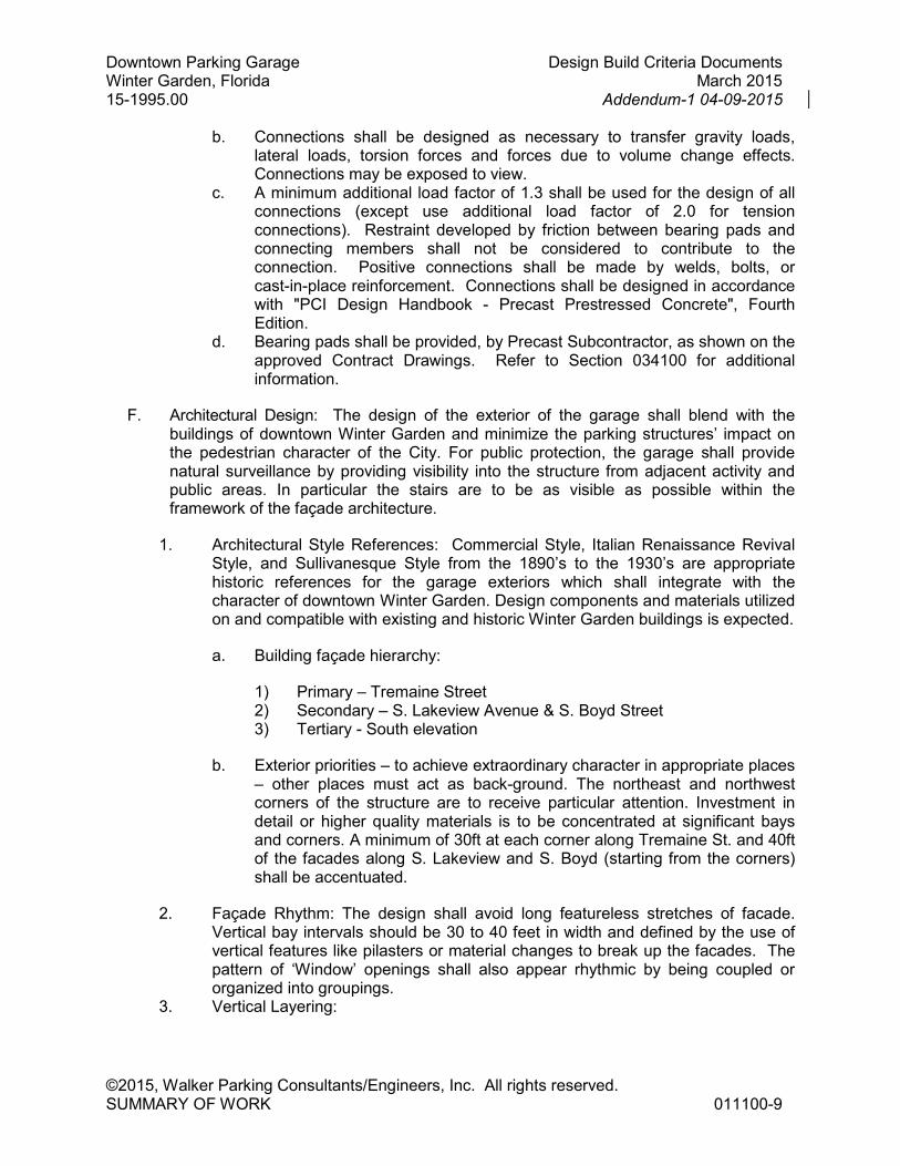
b. Connections shall be designed as necessary to transfer gravity loads, lateral loads, torsion forces and forces due to volume change effects. Connections may be exposed to view.
c. A minimum additional load factor of 1.3 shall be used for the design of all connections (except use additional load factor of 2.0 for tension connections). Restraint developed by friction between bearing pads and connecting members shall not be considered to contribute to the connection. Positive connections shall be made by welds, bolts, or cast-in-place reinforcement. Connections shall be designed in accordance with "PCI Design Handbook - Precast Prestressed Concrete", Fourth Edition.
d. Bearing pads shall be provided, by Precast Subcontractor, as shown on the approved Contract Drawings. Refer to Section 034100 for additional information.
F. Architectural Design: The design of the exterior of the garage shall blend with the buildings of downtown Winter Garden and minimize the parking structures’ impact on the pedestrian character of the City. For public protection, the garage shall provide natural surveillance by providing visibility into the structure from adjacent activity and public areas. In particular the stairs are to be as visible as possible within the framework of the façade architecture.
1. Architectural Style References: Commercial Style, Italian Renaissance Revival Style, and Sullivanesque Style from the 1890’s to the 1930’s are appropriate historic references for the garage exteriors which shall integrate with the character of downtown Winter Garden. Design components and materials utilized on and compatible with existing and historic Winter Garden buildings is expected.
a. Building façade hierarchy:
1) Primary – Tremaine Street 2) Secondary – S. Lakeview Avenue & S. Boyd Street 3) Tertiary - South elevation
b. Exterior priorities – to achieve extraordinary character in appropriate places – other places must act as back-ground. The northeast and northwest corners of the structure are to receive particular attention. Investment in detail or higher quality materials is to be concentrated at significant bays and corners. A minimum of 30ft at each corner along Tremaine St. and 40ft of the facades along S. Lakeview and S. Boyd (starting from the corners) shall be accentuated.
2. Façade Rhythm: The design shall avoid long featureless stretches of facade. Vertical bay intervals should be 30 to 40 feet in width and defined by the use of vertical features like pilasters or material changes to break up the facades. The pattern of ‘Window’ openings shall also appear rhythmic by being coupled or organized into groupings.
3. Vertical Layering:
Downtown Parking Garage Design Build Criteria Documents Winter Garden, Florida March 2015 15-1995.00 Addendum-1 04-09-2015
©2015, Walker Parking Consultants/Engineers, Inc. All rights reserved. SUMMARY OF WORK 011100-10
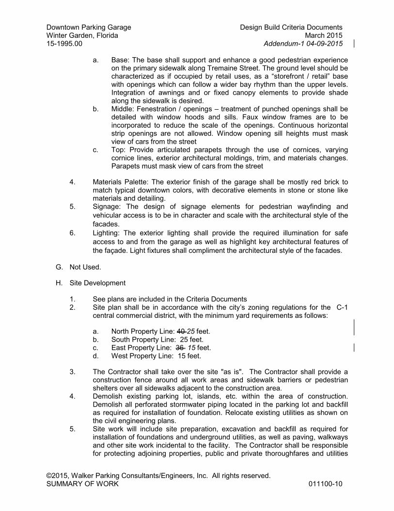
a. Base: The base shall support and enhance a good pedestrian experience on the primary sidewalk along Tremaine Street. The ground level should be characterized as if occupied by retail uses, as a “storefront / retail” base with openings which can follow a wider bay rhythm than the upper levels. Integration of awnings and or fixed canopy elements to provide shade along the sidewalk is desired.
b. Middle: Fenestration / openings – treatment of punched openings shall be detailed with window hoods and sills. Faux window frames are to be incorporated to reduce the scale of the openings. Continuous horizontal strip openings are not allowed. Window opening sill heights must mask view of cars from the street
c. Top: Provide articulated parapets through the use of cornices, varying cornice lines, exterior architectural moldings, trim, and materials changes. Parapets must mask view of cars from the street
4. Materials Palette: The exterior finish of the garage shall be mostly red brick to match typical downtown colors, with decorative elements in stone or stone like materials and detailing.
5. Signage: The design of signage elements for pedestrian wayfinding and
vehicular access is to be in character and scale with the architectural style of the
facades.
6. Lighting: The exterior lighting shall provide the required illumination for safe
access to and from the garage as well as highlight key architectural features of
the façade. Light fixtures shall compliment the architectural style of the facades.
G. Not Used.
H. Site Development
1. See plans are included in the Criteria Documents 2. Site plan shall be in accordance with the city’s zoning regulations for the C-1
central commercial district, with the minimum yard requirements as follows:
a. North Property Line: 40 25 feet. b. South Property Line: 25 feet. c. East Property Line: 36 15 feet. d. West Property Line: 15 feet.
3. The Contractor shall take over the site "as is". The Contractor shall provide a construction fence around all work areas and sidewalk barriers or pedestrian shelters over all sidewalks adjacent to the construction area.
4. Demolish existing parking lot, islands, etc. within the area of construction. Demolish all perforated stormwater piping located in the parking lot and backfill as required for installation of foundation. Relocate existing utilities as shown on the civil engineering plans.
5. Site work will include site preparation, excavation and backfill as required for installation of foundations and underground utilities, as well as paving, walkways and other site work incidental to the facility. The Contractor shall be responsible for protecting adjoining properties, public and private thoroughfares and utilities
Downtown Parking Garage Design Build Criteria Documents Winter Garden, Florida March 2015 15-1995.00 Addendum-1 04-09-2015
©2015, Walker Parking Consultants/Engineers, Inc. All rights reserved. SUMMARY OF WORK 011100-11
from damage due to his operations. Excess excavation and suitable material will be disposed of off the site, designated by the Owner.
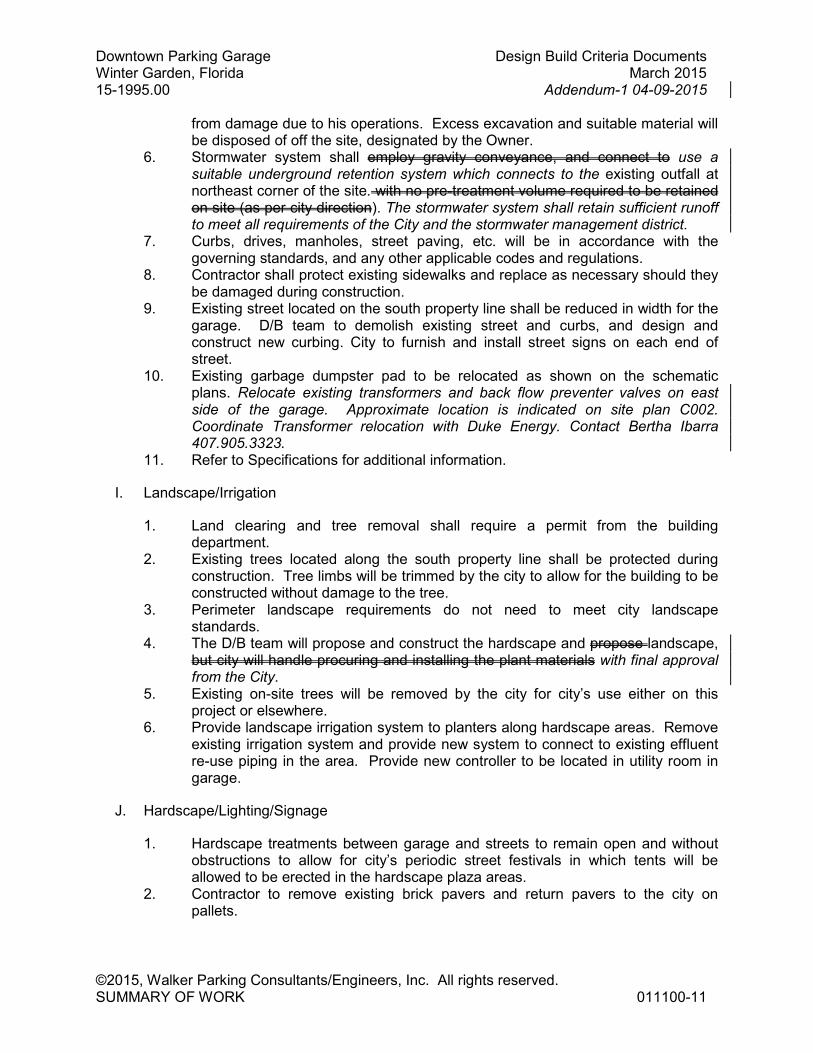
6. Stormwater system shall employ gravity conveyance, and connect to use a suitable underground retention system which connects to the existing outfall at northeast corner of the site. with no pre-treatment volume required to be retained on site (as per city direction). The stormwater system shall retain sufficient runoff to meet all requirements of the City and the stormwater management district.
7. Curbs, drives, manholes, street paving, etc. will be in accordance with the governing standards, and any other applicable codes and regulations.
8. Contractor shall protect existing sidewalks and replace as necessary should they be damaged during construction.
9. Existing street located on the south property line shall be reduced in width for the garage. D/B team to demolish existing street and curbs, and design and construct new curbing. City to furnish and install street signs on each end of street.
10. Existing garbage dumpster pad to be relocated as shown on the schematic plans. Relocate existing transformers and back flow preventer valves on east side of the garage. Approximate location is indicated on site plan C002. Coordinate Transformer relocation with Duke Energy. Contact Bertha Ibarra 407.905.3323.
11. Refer to Specifications for additional information.
I. Landscape/Irrigation
1. Land clearing and tree removal shall require a permit from the building department.
2. Existing trees located along the south property line shall be protected during construction. Tree limbs will be trimmed by the city to allow for the building to be constructed without damage to the tree.
3. Perimeter landscape requirements do not need to meet city landscape standards.
4. The D/B team will propose and construct the hardscape and propose landscape, but city will handle procuring and installing the plant materials with final approval from the City.
5. Existing on-site trees will be removed by the city for city’s use either on this project or elsewhere.
6. Provide landscape irrigation system to planters along hardscape areas. Remove existing irrigation system and provide new system to connect to existing effluent re-use piping in the area. Provide new controller to be located in utility room in garage.
J. Hardscape/Lighting/Signage
1. Hardscape treatments between garage and streets to remain open and without obstructions to allow for city’s periodic street festivals in which tents will be allowed to be erected in the hardscape plaza areas.
2. Contractor to remove existing brick pavers and return pavers to the city on pallets.

Downtown Parking Garage Design Build Criteria Documents Winter Garden, Florida March 2015 15-1995.00 Addendum-1 04-09-2015
©2015, Walker Parking Consultants/Engineers, Inc. All rights reserved. SUMMARY OF WORK 011100-12
3. Hardscape materials may include decorative concrete (colored or plain), concrete unit pavers, concrete sidewalks, or a combination of these, all of which shall be designed to relate to the building and surrounding area hardscapes.
4. Bike racks shall be provided to allow for twelve (12) spaces, which may be in the form of two (2), six (6) space post and hitch bike racks, to be located at city’s direction..
5. City will remove existing light poles and electric vehicle charging station. 6. New lighting shall be proposed and installed by the D/B team. 7. Provide outdoor electrical outlets or connectors in the plaza area in a manner
that does not provide a tripping hazard and are well protected from the elements.
K. Concrete
1. Provide for:
a. Sealed, tooled control/construction joints shall be installed in cast-in-place concrete topping wherever there are joints in the precast concrete below. Control joints may be centered over precast joints, but shall be provided at both faces of beam.
b. Joints between precast tees forming floor surfaces shall be sealed. c. Sealed control/construction joints shall be provided at all intersections
between walls and floors, and columns and floors. d. Sealed expansion joints at all locations where automobiles or pedestrians
cross over structural isolation joints and at top level at all structural isolation joints.
e. Refer to Specifications Division 03 for additional information.
L. Masonry
1. Standard masonry units will be used for the non-load bearing partition walls of the electrical room. Concrete masonry units will conform to ASTM C90. Truss type reinforcement will be provided in every other block course. Walls will be reinforced as required by code and by design. All work will comply with the National Concrete Masonry Association and Brick Institute of America standards.
2. Refer to Specifications Division 04 for additional information.
M. Metals
1. Miscellaneous metals shall consist of steel pipe handrails, steel plates and wire strands. Materials shall conform to ASTM-A501, ASTM-A36, ASTM-A307, as applicable. Guardrail strands, if used within the parking areas, shall be 3/8" diameter galvanized cable. All exposed metal, except aluminum and hot-dip galvanized shall be given one shop coat of protective primer with field coats by finish painter.
2. Refer to Specifications Division 05 for additional information.
N. Carpentry
Downtown Parking Garage Design Build Criteria Documents Winter Garden, Florida March 2015 15-1995.00 Addendum-1 04-09-2015
©2015, Walker Parking Consultants/Engineers, Inc. All rights reserved. SUMMARY OF WORK 011100-13
1. Carpentry items will generally consist of wood blocking at the stairtower roof edges. All wood shall be given a three-minute immersion in wood life preservative or equivalent. Concrete form carpentry is included in Division 3.
2. Refer to Specifications Division 06 for additional information.
O. Thermal and Moisture Protection
1. Provide sealant at control/construction joint locations noted in specifications section 011100-1.8 K and in 079233.
2. Provide expansion joint sealant at isolation joint locations noted in specifications sections 011100-1.8 K and in 079500.
3. Provide damp-proofing where required below grade. 4. Provide protective concrete surface sealer and traffic topping on surfaces noted
in specification Section 071800 and 071900. 5. Provide a modified bituminous roof surface at stair and stair elevator towers. 6. Refer to Specifications Division 07 for additional information.
P. Doors and Windows
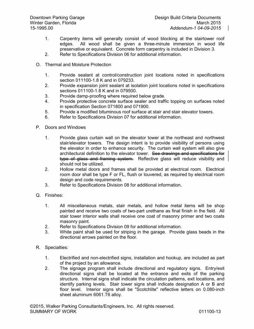
1. Provide glass curtain wall on the elevator tower at the northeast and northwest stair/elevator towers. The design intent is to provide visibility of persons using the elevator in order to enhance security. The curtain wall system will also give architectural definition to the elevator tower. See drawings and specifications for type of glass and framing system. Reflective glass will reduce visibility and should not be utilized.
2. Hollow metal doors and frames shall be provided at electrical room. Electrical room door shall be type F or FL, flush or louvered, as required by electrical room design and code requirements.
3. Refer to Specifications Division 08 for additional information.
Q. Finishes:
1. All miscellaneous metals, stair metals, and hollow metal items will be shop painted and receive two coats of two-part urethane as final finish in the field. All stair tower interior walls shall receive one coat of masonry primer and two coats masonry paint.
2. Refer to Specifications Division 09 for additional information. 3. White paint shall be used for striping in the garage. Provide glass beads in the
directional arrows painted on the floor.
R. Specialties:
1. Electrified and non-electrified signs, installation and hookup, are included as part of the project by an allowance.
2. The signage program shall include directional and regulatory signs. Entry/exit directional signs shall be located at the entrance and exits of the parking structure. Internal signs shall indicate the circulation patterns, exit locations, and identify parking levels. Stair tower signs shall indicate designation A or B and floor level. Interior signs shall be "Scotchlite" reflective letters on 0.080-inch sheet aluminum 6061.T6 alloy.
Downtown Parking Garage Design Build Criteria Documents Winter Garden, Florida March 2015 15-1995.00 Addendum-1 04-09-2015
©2015, Walker Parking Consultants/Engineers, Inc. All rights reserved. SUMMARY OF WORK 011100-14
3. Refer to Specifications Division 10 for additional information.
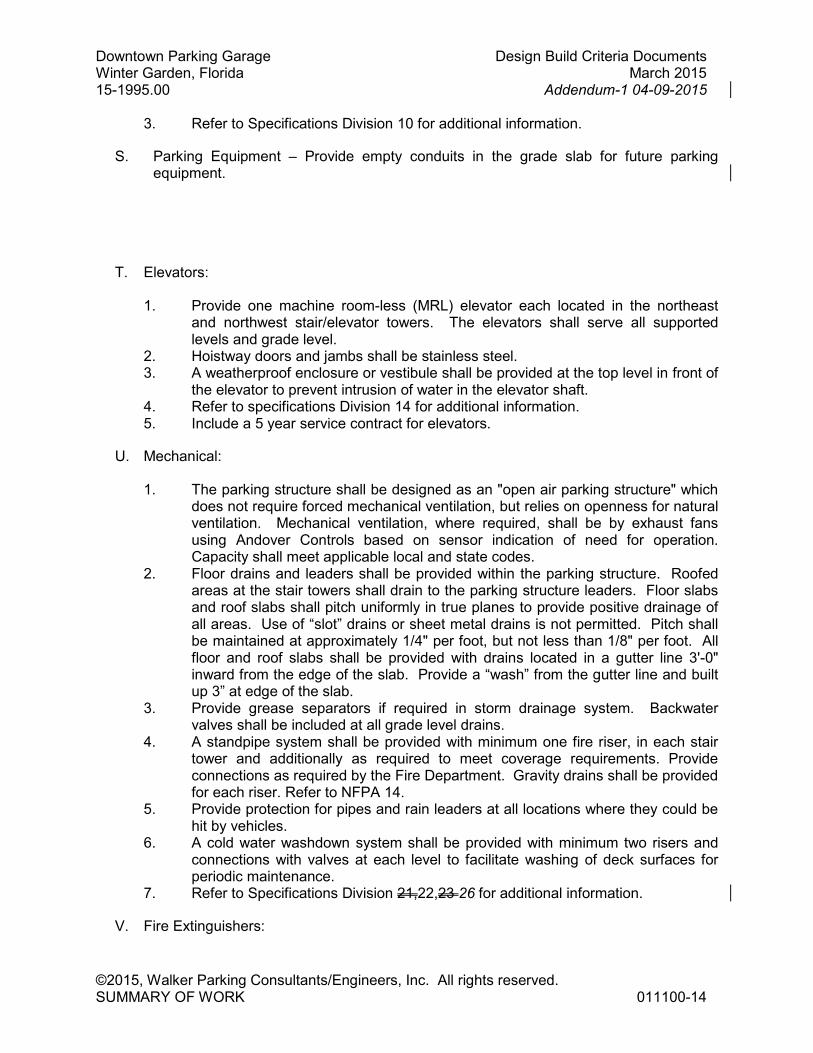
S. Parking Equipment – Provide empty conduits in the grade slab for future parking equipment.
T. Elevators:
1. Provide one machine room-less (MRL) elevator each located in the northeast and northwest stair/elevator towers. The elevators shall serve all supported levels and grade level.
2. Hoistway doors and jambs shall be stainless steel. 3. A weatherproof enclosure or vestibule shall be provided at the top level in front of
the elevator to prevent intrusion of water in the elevator shaft. 4. Refer to specifications Division 14 for additional information. 5. Include a 5 year service contract for elevators.
U. Mechanical:
1. The parking structure shall be designed as an "open air parking structure" which does not require forced mechanical ventilation, but relies on openness for natural ventilation. Mechanical ventilation, where required, shall be by exhaust fans using Andover Controls based on sensor indication of need for operation. Capacity shall meet applicable local and state codes.
2. Floor drains and leaders shall be provided within the parking structure. Roofed areas at the stair towers shall drain to the parking structure leaders. Floor slabs and roof slabs shall pitch uniformly in true planes to provide positive drainage of all areas. Use of “slot” drains or sheet metal drains is not permitted. Pitch shall be maintained at approximately 1/4" per foot, but not less than 1/8" per foot. All floor and roof slabs shall be provided with drains located in a gutter line 3'-0" inward from the edge of the slab. Provide a “wash” from the gutter line and built up 3” at edge of the slab.
3. Provide grease separators if required in storm drainage system. Backwater valves shall be included at all grade level drains.
4. A standpipe system shall be provided with minimum one fire riser, in each stair tower and additionally as required to meet coverage requirements. Provide connections as required by the Fire Department. Gravity drains shall be provided for each riser. Refer to NFPA 14.
5. Provide protection for pipes and rain leaders at all locations where they could be hit by vehicles.
6. A cold water washdown system shall be provided with minimum two risers and connections with valves at each level to facilitate washing of deck surfaces for periodic maintenance.
7. Refer to Specifications Division 21,22,23 26 for additional information.
V. Fire Extinguishers:

Downtown Parking Garage Design Build Criteria Documents Winter Garden, Florida March 2015 15-1995.00 Addendum-1 04-09-2015
©2015, Walker Parking Consultants/Engineers, Inc. All rights reserved. SUMMARY OF WORK 011100-15
1. Provide fire extinguishers throughout the facility as required by code and NFPA 10.
W. Electrical:
1. Panel boards, contactors, time switches and other related electrical devices shall be located in an electrical equipment room within the facility.
2. Lighting within the parking structure shall be provided utilizing ceiling mounted fixtures equipped with LED lamps. Fixtures shall be provided as specified in light fixture schedule and as on plans. Vandal resistant fixtures shall be located as specified on plans. Fixtures shall provide minimum average maintained illuminance of six foot candles with average to minimum uniformity ratio of four to one at floor level; and minimum average illuminance of six foot-candles with average to minimum uniformity ratio of three to one (with minimum of two foot-candles at bumper wall) at a plane 30" above floor. Lighting level of approximately 50 foot-candles shall be provided at entry and exit lanes and at stairs. The top level shall be lighted with pulse start metal halide or LED pole mounted fixtures providing 2 foot-candle average illumination, with average to minimum uniformity ratio of three to one at surface and minimum of one foot candle at bumper wall. Refer to Specification Section 265001 for Lighting Design Performance Criteria. Top level Poles poles shall be 20 feet steel square poles mounted on top of columns extended four feet above top level and shall be hinged for maintenance of fixtures. All lights shall be circuited to provide optimum lighting levels for each area considering exterior exposure and function. Stairwell lighting shall be fluorescent. Exposed conduits shall be used under the post-tensioned or precast slabs. Emergency lights shall be provided per code requirements.
3. Refer to City of Winter Garden Ordinance Article X, Division 4 for External Site Lighting requirements
4. Provide empty conduits for future CCTV system. 5. Provide duplex electrical exterior type outlets at each stair and elevator landing.
Outlets shall be waterproof and with ground fault provision. 6. Provide all systems described in Specification Sections of Division 26.
X. Emergency Phones
1. Provide two blue-light phones per floor for all floors. One each at each of the stair towers.
1.9 ALLOWANCES
A. Refer to section 01210
1.10 AS-BUILT DRAWINGS
A. At the project closeout, the selected Design/Build Contractor shall submit to the Owner a set of as-built drawings and specifications reflecting as-built conditions of the project. A set of as-built drawings shall consist of size “E” or “F” prints. In addition, these
Downtown Parking Garage Design Build Criteria Documents Winter Garden, Florida March 2015 15-1995.00 Addendum-1 04-09-2015
©2015, Walker Parking Consultants/Engineers, Inc. All rights reserved. SUMMARY OF WORK 011100-16
documents shall be provided on an IBM-PC compatible CD-ROM in AutoCAD version 2014 or higher format for drawings and PDF format for specifications.
END OF SECTION 011100
© Copyright 2015. All rights reserved. No part of this document may be reproduced in any form or by any means without permission from Walker Parking Consultants/Engineers Inc.
S. B
OY
D S
TRE
ET
TREMAINE STREET
S. L
AK
EV
IEW
AV
EN
UE
SUBJECTPROPERTY
15-1995.00
TLS
TFZ
S. B
OY
D S
TRE
ET
TREMAINE STREET
S. L
AK
EV
IEW
AV
EN
UE
WASH DOWN
WA
SH D
OW
N
UP
RA
MP
+/-9.5%
FDFDFDFD
FD FDFD FD
FD FDFD
15-1995.00
TLS
TFZ