Embed Size (px)
Citation preview

DP-350 manual.qxd 5/19/10 2:16 PM Page 1

10. Base 11. Table 12. Head assembly13. Switch14. Depth indicator15. Depth indicator lock nuts16. Depth rod17. Depth rod support18. 13mm Keyed chuck
19. Column support bolts x 320. 3mm Allen key21. 4mm Allen key 22. Chuck key 23. Table support lock 24. Depth scale
Motor size: 350WInput: 230-240V ~ 50HzNo load speed: 580, 850, 1220, 1650, 2650/minChuck: 13mm KeyedSpindle travel: 50mmSpindle shaft to column distance: 104mmColumn height: 395mmProtection class: 1 (Earthed Appliance)Weight: 16.4kg
Know Your Product
1
3
1
SPECIFICATIONS – MODEL NO. DP-350
18
1. Pulley cover2. Pulley cover knob3. Belt tension knob4. Head lock screws 5. Feed wheel hub6. Feed wheel handles 7. Table support 8. Column 9. Column support
2
4
5
6
7
8
9
11
12
1314
15
16
19
23
20
10
17
21
22
24
DP-350 manual.qxd 5/19/10 2:16 PM Page 2

2
TABLE OF CONTENTS
SPECIFICATIONS…………………………………………
INTRODUCTION………………………………………...
ELECTRICAL SAFETY…………………………………...
GENERAL SAFETY INSTRUCTIONS…………………..
ADDITIONAL SAFETY INSTRUCTIONS FOR DRILL PRESSES…
ASSEMBLY………………………………………………..
ADJUSTMENTS………………………………………….
OPERATION………………………………………….…..
MAINTENANCE………………………………………….
SPARE PARTS…………………………………………….
TROUBLESHOOTING…………………………………..
DESCRIPTION OF SYMBOLS…………………………..
CONTENTS………………………………………………
WARRANTY………………………………………………
Page 1
Page 3
Page 3
Page 4
Page 6
Page 8
Page 10
Page 12
Page 12
Page 13
Page 13
Page 14
Page 14
Page 15
DP-350 manual.qxd 5/19/10 2:16 PM Page 3

INTRODUCTION
SAFETY INSTRUCTIONS
ELECTRICAL SAFETY
3
Congratulations on purchasing an Ozito Drill Press. We aim to provide quality tools at an affordable price.We hope you will enjoy using this tool for many years.
Your Ozito DP-350 Drill Press has been designed foraccurate drilling into steel, timber and plastic. It isintended for DIY use only.
WARNING! When using mains-powered equipment, basic safetyprecautions, including the following, should always be followed to reducerisk of fire, electric shock, personal injury and material damage.
Read and understand the manual prior to operating this tool.
Save these instructions and other documents supplied with this tool forfuture reference.
The electric motor has been designed for 230V and 240V only. Always check that thepower supply corresponds to the voltage on the rating plate.
Note: The supply of 230V and 240V on Ozito tools are interchangeable forAustralia and New Zealand.
If the supply cord is damaged, it must be replaced by an electrician or a powertool repairer in order to avoid a hazard.
Using an Extension Lead
Always use an approved extension lead suitable for the power input of this tool.Before use, inspect the extension lead for signs of damage, wear and ageing.Replace the extension lead if damaged or defective.
When using an extension lead on a reel, always unwind the lead completely. Use ofan extension lead not suitable for the power input of the tool or which is damagedor defective may result in a risk of fire and/or electric shock.
It is recommended that the extension lead is a maximum of 25m in length. Do Notuse multiple extension leads.
!!
DP-350 manual.qxd 5/19/10 2:16 PM Page 4

4
GENERAL SAFETY INSTRUCTIONS
WARNING! Read all instructions. Failure to follow all instructions listedbelow may result in electric shock, fire and/or serious injury. The term “PowerTool” in all of the warnings listed below refers to your mains operated(corded) power tool or battery operated (cordless) power tool.
SAVE THESE INSTRUCTIONS
1) WORK AREA
a) Keep work area clean and well lit. Cluttered and dark areas invite accidents.
b) Do not operate power tools in explosive atmospheres, such as in thepresence of flammable liquids, gases, or dust. Power tools create sparks whichmay ignite the dust or fumes.
c) Keep children and bystanders away while operating a power tool. Distractionscan cause you to lose control.
2) ELECTRICAL SAFETY
a) Power tool plugs must match the outlet. Never modify the plug in any way.Do not use any adapter plugs with earthed (grounded) power tools.Unmodified plugs and matching outlets will reduce risk of electric shock.
b) Avoid body contact with earthed or grounded surfaces such as pipes,radiators, ranges and refrigerators. There is an increased risk of electric shock ifyour body is earthed or grounded.
c) Do not expose power tools to rain or wet conditions. Water entering a powertool will increase the risk of electric shock.
d) Do not abuse the cord. Never use the cord for carrying, pulling or unpluggingthe power tool. Keep cord away from heat, oil, sharp edges or moving parts.Damaged or entangled cords increase the risk of electric shock.
e) When operating a power tool outdoors, use an extension cord suitable foroutdoor use. Use of a cord suitable for outdoor use reduces the risk of electric shock.
3) PERSONAL SAFETY
a) Stay alert, watch what you are doing and use common sense when operating apower tool. Do not use a power tool while you are tired or under the influenceof drugs, alcohol or medication. A moment of inattention while operating powertools may result in serious personal injury.
b) Use safety equipment. Always wear eye protection. Safety equipment such asdust mask, non-skid safety shoes, hard hat, or hearing protection used forappropriate conditions will reduce personal injuries.
c) Avoid accidental starting. Ensure the switch is in the off position beforeplugging in. Carrying power tools with your finger on the switch or plugging inpower tools that have the switch on invites accidents.
d) Remove any adjusting key or wrench before turning the power tool on. Awrench or a key left attached to a rotating part of the power tool may result inpersonal injury.
e) Do not overreach. Keep proper footing and balance at all times. This enablesbetter control of the power tool in unexpected situations.
!!
DP-350 manual.qxd 5/19/10 2:16 PM Page 5

5
GENERAL SAFETY INSTRUCTIONS (cont.)
f) Dress properly. Do not wear loose clothing or jewellery. Keep your hair,clothing and gloves away from moving parts. Loose clothes, jewellery orlong hair can be caught in moving parts.
g) If devices are provided for the connection of dust extraction and collectionfacilities, ensure these are connected and properly used. Use of thesedevices can reduce dust related hazards.
4) POWER TOOL USE AND CARE
a) Do not force the power tool. Use the correct power tool for yourapplication. The correct power tool will do the job better and safer at the ratefor which it was designed.
b) Do not use the power tool if the switch does not turn it on and off. Anypower tool that can not be controlled with the switch is dangerous and must be repaired.
c) Disconnect the plug from the power source before making anyadjustments, changing accessories, or storing power tools. Such preventivesafety measures reduce the risk of starting the power tool accidentally.
d) Store idle power tools, unplugged & out of the reach of children and donot allow persons unfamiliar with the power tool or these instructions tooperate the power tool. Power tools are dangerous in the hands of untrained users.
e) Maintain power tools. Check for misalignment or binding of moving parts,breakage of parts and any other condition that may affect the power toolsoperation. If damaged, have the power tool repaired before use. Manyaccidents are caused by poorly maintained power tools.
f) Keep cutting tools sharp and clean. Properly maintained cutting tools withsharp cutting edges are less likely to bind and are easier to control.
g) Use the power tool, accessories and tool bits etc., in accordance withthese instructions and in the manner intended for the particular type ofpower tool, taking into account the working conditions and the work tobe performed. Use of the power tool for operations different from intendedcould result in a hazardous situation.
h) This appliance is not intended for use by persons (including children) withreduced physical, sensory or mental capabilities, or lack of experience andknowledge, unless they have been given supervision or instruction concerninguse of the appliance by a person responsible for their safety.
i) Children should be supervised to ensure that they do not play with the appliance.
5) SERVICE
a) Have your power tool serviced by a qualified repair person using onlyidentical replacement parts. This will ensure that the safety of the power tool is maintained.
b) If the supply cord is damaged, it must be replaced by the manufacturer, itsservice agent or similarly qualified persons in order to avoid a hazard.
DP-350 manual.qxd 5/19/10 2:16 PM Page 6

ADDITIONAL SAFETY INSTRUCTIONS FOR DRILL PRESSES
6
!! WARNING! For your own safety, do not try to use your drill press or plug itin until it is completely assembled and installed according to the instructionsand until you have read and understood the following:
1. Your drill press must be bolted securely to a workbench. In addition, if there is anytendency for your drill press to move during certain operations, bolt theworkbench to the floor.
2. This drill press is intended for use in dry conditions and indoor use only.
3. Always wear safety goggles which comply to a recognised standard. Use a face ordust mask along with safety goggles if the drilling operation is dusty. Use earprotectors, especially during extended periods of operation.
4. Do not try to drill material too small to be securely held. Do not drill material thatdoes not have a flat surface unless it is clamped securely.
5. Always keep hands out of the path of the drill bit. Avoid awkward hand positionswhere a sudden slip could cause your hand to move into the drill bit.
6. Do not install or use any drill bit that exceeds 175mm (7 inches) in length orextends more than 150mm (6 inches) below the chuck jaws. They can suddenlybend outwards or break.
7. Do not use wire wheels, router bits, shaper cutters, circle (fly) cutters or rotaryplaners on this drill press.
8. When cutting a large piece of material make sure it is fully supported at the table height.
9. Do not perform any operation freehand. Always hold the workpiece firmly againstthe table so it will not rock or twist. Use clamps or a vice for unstable workpieces.
10. Make sure there are no nails or foreign objects in the part of the workpiece to be drilled.
11. Whenever possible, position the workpiece to contact the left side of the column;if it is too short or the table is tilted, clamp solidly to the table.
12. If the workpiece overhangs the table such that it will fall or tip if not held, clamp itto the table or provide auxiliary support.
13. Set the drill press to a speed appropriate to the job.
14. Do not start the drill press while the drill bit is touching the workpiece.
15. When using a drill press vice, always fasten it to the table.
16. Make sure all clamps and locks are firmly tightened before drilling.
17. Securely lock the head and table support to the column, and the table to the tablesupport before operating your drill press.
18. Never turn your drill press on before clearing the table of all objects (tools, scrapsof wood etc.)
19. Before starting the operation, jog the motor switch to make sure the drill bit doesnot wobble or vibrate.
20. Let the spindle reach full speed before starting to drill. If your drill press makes anunfamiliar noise or if it vibrated excessively, stop immediately, turn the drill pressoff and unplug it. Do not restart until the problem is corrected.
DP-350 manual.qxd 5/19/10 2:16 PM Page 7

!!
7
21. Do not perform layout assembly or setup work on the table while the drill pressis in operation.
22. Do not exceed the rpm stated on the bit or accessory. See the instructions thatcome with the accessory.
23. When drilling large diameter holes, clamp the workpiece firmly to the table.Otherwise, the bit may grab and spin the workpiece at high speed. Do not usefly cutters or multiple-part cutters, as they can come apart or becomeunbalanced in use.
24. Make sure the spindle has come to a complete stop before touching the workpiece.
25. To avoid injury from accidental starting, always turn the switch off and unplugthe drill press before installing or removing any accessory attachment ormaking any adjustment.
26. This appliance is not intended for use by persons (including children) withreduced physical, sensory or mental capabilities, or lack of experience andknowledge, unless they have been given supervision or instruction concerninguse of the appliance by a person responsible for their safety.
27. Children should be supervised to ensure that they do not play with the appliance.
28. If the supply cord is damaged, it must be replaced by the manufacturer, itsservice agent or similarly qualified persons in order to avoid a hazard.
CAUTION: Do not expose to rain or use in damp locations.
WARNING! For your own safety read instruction manual before operatingdrill press. Wear eye protection, do not wear gloves, necktie or looseclothing, clamp workpiece or brace against column to prevent rotation, userecommended speed for drill accessory and workpiece material.
ADDITIONAL SAFETY INSTRUCTIONS FOR DRILL PRESSES (cont.)
DP-350 manual.qxd 5/19/10 2:16 PM Page 8

8
ASSEMBLY
!! WARNING! During assembly ensure the drill press is disconnected from the power supply.
1. Carefully remove contents from the packaging.
2. Select a firm, level surface on which to assemble the drill press.
3. Select the base (10) (Fig. 1) and align the column (8) over the large hole (Fig. 2),align the holes in the column support (9) with those in the base (10) and secure inplace using the 3 column support bolts (19), spring and flat washers (supplied) (Fig. 3).Fit the spring washer over the bolt followed by the flat washer and using a 12mmspanner or shifter (not supplied) securely tighten all 3 column support bolts (19).
4. Slide the table support (7)over the column (8) andusing the table supportlock (23), secure the table(11) into the desiredposition (Fig. 4).
5. Lift the head assembly (12)and slide it down onto thecolumn (8) as far as it willgo. Secure in position by tightening the two head lock screws (4) in a clockwisedirection using the 4mm allen key (21) (Fig. 5).
Fig. 1 Fig. 2 Fig. 3
Fig. 4 Fig. 5
DP-350 manual.qxd 5/19/10 2:16 PM Page 9

9
ASSEMBLY (cont.)
6. To fit the feed wheel handles (6),screw them into the feed wheel hub(5) (Fig. 6 & 7).
7. To fit the 13mm keyed chuck (18), first place a piece oftimber on the table (11) and position the 13mm keyedchuck (18) with the jaws retracted under the drive shaft.Raise the table (11) toward the drive shaft until the 13mmkeyed chuck (18) is approximately 25mm from the driveshaft (Fig. 8).
8. To secure the 13mm keyed chuck (18) to the drive shaftgently lower the drive shaft using the feed wheel handles(6) (Fig. 9) until the drive shaft is pushed into the hole ofthe 13mm keyed chuck (18). Because the hole in thechuck is tapered, a gentle tap on the timber is all that isrequired to secure the 13mm keyed chuck (18) onto thedrive shaft.
Fig. 8
Fig. 9
Fig. 6 Fig. 7
DP-350 manual.qxd 5/19/10 2:16 PM Page 10

!!
10
ADJUSTMENTS
WARNING! Before making any adjustments, ensure the drill press isdisconnected from the mains power.
Adjusting the Table Height
1. Loosen the table support lock (23) (Fig. 14).
2. Set the desired table height and tighten the table support lock (23) to secure thetable (11) in position (Fig. 15).
Adjusting the Table Angle
The table (11) can be adjusted up to 45° tothe left or right.
1. Loosen the table support angle bolt(located below the table) by turning it anti-clockwise using an 18mm spanner or shifter (not supplied) (Fig. 16). Alignand set the desired angle.
2. Tighten the table support angle bolt in a clockwise direction using an 18mmspanner or shifter (not supplied) to secure the table (11) in position.
CAUTION: When the table is angled/tilted, ensure the workpiece is clamped to the table (11).
Installing and Removing Drill Bits
1. Loosen the chuck jaws of the drill pressusing the chuck key (22), rotate in an anti-clockwise direction (Fig. 18).
2. Insert the drill bit fully into the 13mmkeyed chuck (18) (Fig. 19).
3. Whilst holding the drill bit in one hand rotate the top collarof the 13mm keyed chuck (18) in a clockwise direction.Ensure you tighten all 3 holes in the 13mm keyed chuck (18)using the chuck key (22) to securely tighten the jaws and holdthe drill bit in position (Fig. 20).
Pre-setting the Drilling Depth
1. Loosen the depth indicator lock nuts (15) by turning in an anti-clockwise direction.
2. Ensure the drill bit is secure in the 13mm keyed chuck (18) and tightened correctly.Lower the feed wheel handles (6) to the desired depth using the depth scale (24).
Fig. 14 Fig. 15
Fig. 16 Fig. 17
Fig. 18 Fig. 19
Fig. 20
DP-350 manual.qxd 5/19/10 2:16 PM Page 11

ADJUSTMENTS (cont.)
11
3. Whilst holding the feed wheel handles (6), tighten thedepth indicator lock nuts (15) until they touch the metalstop (Fig. 21).
4. Lift the feed wheel handles up and then proceed to operatethe drill press.
5. To disable the depth lock loosen the depth indicator locknuts (15) and reset to the desired position. Having thesein the highest position on the depth rod (16) will providemaximum drilling capacity.
Changing the Speed
The speed of the drill press can be changedby adjusting the belt on the pulley system.Using a smaller pulley step on thespindle/chuck increases the drill speed. Usinga larger pulley step on the spindle/chuckdecreases the drill speed.
1. Loosen the belt tension knob(3) (Fig. 22).
2. Push the motor towards thehead assembly (12) and tighten the belt tension knob (3) (Fig. 23).
3. To adjust the belt speed, move the belt pulley step for the speed required. To select a faster drill speed, move the belt up to a smaller step on the spindle/chuck pulley.To select a slower drill speed move the belt down to a larger step on the spindle/chuck pulley.When moving the belt, it is easier to place the belt onto the small pulley first and then turn it onto the larger pulley (Fig. 24).
4. To apply tension to the belt once it has been fittedto a new speed setting, loosen the belt tension knob (3). The belt tension will automatically tensionthe belt to the correct tension, then re-tighten thebelt tension knob (3).
Turning On and Off
ATTENTION: The pulley cover (1) is fitted with asafety switch and must be closed to operate the drill press.
1. Switch the drill press on by pressing the green (I)button on the switch (13) (Fig. 25).
2. Switch the drill press off by pressing the red (O)button on the switch (13).
3. Secure your workpiece to the table (11) if possible, use a vice or clamps (notsupplied).
Fig. 25
Fig. 22 Fig. 23
Fig. 24
Fig. 21
DP-350 manual.qxd 5/19/10 2:16 PM Page 12

OPERATION
12
1. Ensure the drill press is switched off and disconnected from the power supply.
2. Loosen the jaws of the 13mm keyed chuck (18) with the chuck key (22) by turningin an anti-clockwise direction and insert the selected drill bit into the 13mm keyedchuck (18) as far as it will go.
3. Ensure that the drill bit is centred in the 13mm keyed chuck (18) and tighten thechuck jaws with the chuck key (22) in a clockwise direction. Tighten all three holesto ensure the drill bit is secured evenly by each jaw.
4. Select your drilling depth and secure the depth indicator lock nuts (15) in position.
5. Adjust the table (11) to your desired position.
6. Slowly rotate the feed wheel handles (6) to bring the drill bit down towards thetable (11) and into your workpiece. After drilling a hole, release the feed wheelhandles (6) slowly to return the 13mm keyed chuck (18) to its original position.
Note: Ensure the hole in the centre of the table (11) is aligned with the drill bit. If notaligned, use the 4mm allen key (21) provided to loosen the head assembly (12) on thecolumn support (9) and re-align the head assembly (12). Re-tighten the 2 head lockscrews (4).
7. Continue the operation until the task is completed. When completed, switch thedrill press off by pressing the red (O) button on the switch (13).
1. Ensure the power is disconnected from the drill press prior to any maintenancebeing carried out.
2. Ball bearings are packed with grease at the factory. No further lubrication ofbearings is required.
3. Lubricate all moving parts periodically. Wipe the column, table and base with anoily cloth to keep corrosion to a minimum.
4. Keep air vents clean of dust and dirt.
5. Remove dust and dirt from the drill press regularly with a soft cloth, brush or compressed air.
6. If the power cord is damaged, have it replaced by an electrician or a power tool repairer.
7. Regularly check that all bolts, screws and nuts are securelyfixed as these could work loose during normal operation.
8. If the drive belt will not align with the pulleys. The pulleysmay be worn and need to be replaced. To remove thepulleys, use the 3mm allen key (20) provided. Loosen inan anti-clockwise direction (Fig. 26).
Note: Ozito Industries will not be responsible for anydamage or injuries caused by the repair of the drill press by an unauthorised person orby mishandling of the drill press.
MAINTENANCE
Fig. 26
DP-350 manual.qxd 5/19/10 2:16 PM Page 13

TROUBLESHOOTING
13
SPARE PARTS
Limited spare parts are available subject to availability. Please contact your localBunnings Special Orders Desk to order the required spare parts.
Most common spare parts listed below
Spare Part Part No.
Handle Sleeve SPDP350-17
Switch SPDP350-50
Drive Belt SPDP350-67
Problem Cause Solution
Drill press willnot start
Noisy operation
Excessive drillbit wobble
Drill bit bindsin workpiece
Drill bit burns
Power cord not connectedto the mains power supply
Power fault
Power cord damage
Faulty switch or motor
Incorrect belt tension
Bent or damaged drill bit
Drill bit is not securelyplaced in the 13mm keyedchuck
The 13mm keyed chuck isnot installed correctly
Belt tension is set incorrectly
Incorrect speed
Ensure that the power cord isconnected to the mains power
Check the mains power supply
Use an authorised servicecentre to repair or replace
Use an authorised servicecentre to repair or replace
Adjust tension as required
Use a new drill bit
Remove the drill bit and re-insert correctly, ensure thechuck jaws are fully tightened
Ensure you install the 13mmkeyed chuck correctly
Re-adjust the belt tension
Adjust speed as described inthe "changing the speed"section
Pulley cover not secured Check the pulley cover isclosed and lowered correctlyin position
DP-350 manual.qxd 5/19/10 2:16 PM Page 14

1 x 3mm Allen key1 x Chuck key (for chuck)1 x Steel column1 x Table
AUSTRALIA (Head Office)1-23 Letcon Drive, Bangholme Victoria, Australia, 3175 Telephone: 1800 069 486Facsimile: +61 3 9238 5588Website: www.ozito.com.auEmail: [email protected]
Power tools that are no longer usable should not be disposed ofwith household waste but in an environmentally friendly way.Please recycle where facilities exist. Check with your local councilauthority for recycling advice.
Recycling packaging reduces the need for landfill and rawmaterials. Reuse of recycled material decreases pollution in theenvironment. Please recycle packaging where facilities exist.Check with your local council authority for recycling advice.
V Volts Hz Hertz
~ Alternating current W Watts
/min Revolutions or reciprocation per minute
Hp Horse power Regulator compliance mark
Use eye protection Warning
no No load speed
!!
CONTENTS
OZITO INDUSTRIES PTY LTD
14
DESCRIPTION OF SYMBOLS
CARING FOR THE ENVIRONMENT
1 x Head assembly 3 x Feed wheel handles1 x 13mm Keyed chuck 1 x 4mm Allen key
1 x Belt (assembled to pulleys)1 x Base3 x Column support bolts1 x Instruction manual
DP-350 manual.qxd 5/19/10 2:16 PM Page 15
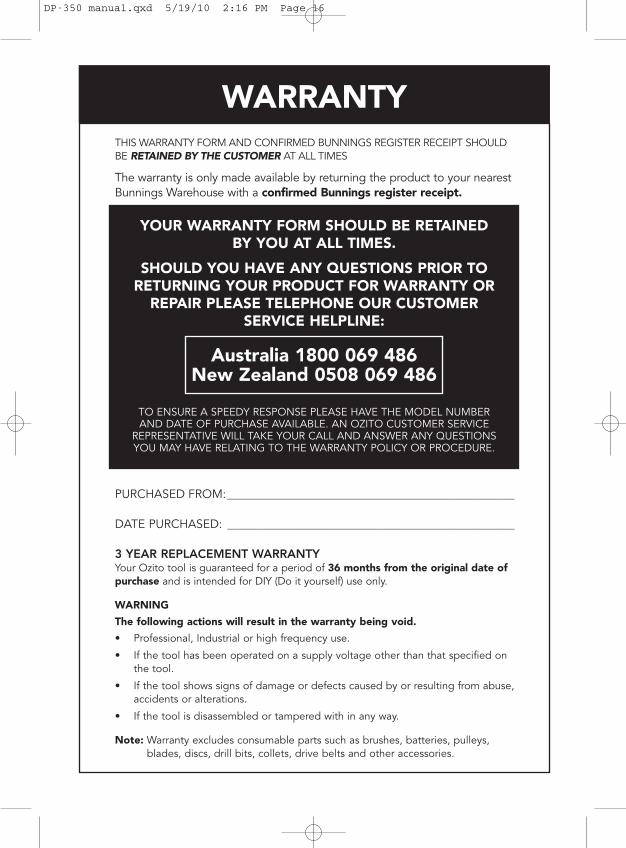
WARRANTYTHIS WARRANTY FORM AND CONFIRMED BUNNINGS REGISTER RECEIPT SHOULDBE RETAINED BY THE CUSTOMER AT ALL TIMES
The warranty is only made available by returning the product to your nearestBunnings Warehouse with a confirmed Bunnings register receipt.
PURCHASED FROM:________________________________________________
DATE PURCHASED: ________________________________________________
3 YEAR REPLACEMENT WARRANTYYour Ozito tool is guaranteed for a period of 36 months from the original date ofpurchase and is intended for DIY (Do it yourself) use only.
WARNING
The following actions will result in the warranty being void.
• Professional, Industrial or high frequency use.
• If the tool has been operated on a supply voltage other than that specified onthe tool.
• If the tool shows signs of damage or defects caused by or resulting from abuse,accidents or alterations.
• If the tool is disassembled or tampered with in any way.
Note: Warranty excludes consumable parts such as brushes, batteries, pulleys,blades, discs, drill bits, collets, drive belts and other accessories.
YOUR WARRANTY FORM SHOULD BE RETAINEDBY YOU AT ALL TIMES.
SHOULD YOU HAVE ANY QUESTIONS PRIOR TORETURNING YOUR PRODUCT FOR WARRANTY OR
REPAIR PLEASE TELEPHONE OUR CUSTOMERSERVICE HELPLINE:
Australia 1800 069 486New Zealand 0508 069 486
TO ENSURE A SPEEDY RESPONSE PLEASE HAVE THE MODEL NUMBERAND DATE OF PURCHASE AVAILABLE. AN OZITO CUSTOMER SERVICE
REPRESENTATIVE WILL TAKE YOUR CALL AND ANSWER ANY QUESTIONSYOU MAY HAVE RELATING TO THE WARRANTY POLICY OR PROCEDURE.
DP-350 manual.qxd 5/19/10 2:16 PM Page 16