Embed Size (px)
Citation preview
Operating Instructions
10/2002
2 HEIDENHAIN
Range of Application ........................................................................................... 3
Conversational Languages .................................................................................. 4
Documentation .................................................................................................... 4
General Conditions for Use of this Software .................................................... 5
System Requirements ......................................................................................... 5
Hardware key (dongle) ...................................................................................... 6Installing the Software........................................................................................ 7
Installation information ...................................................................................... 8Using more than one DataPilot version ............................................................. 8Deinstalling the software ................................................................................... 9Software version ............................................................................................... 9
Dongle Server ..................................................................................................... 10
HL Server ........................................................................................................ 10ALADDIN Monitor ........................................................................................... 11
DataPilot Configuration ..................................................................................... 12
Multi-machine concept .................................................................................... 12DataPilot variants ............................................................................................ 12Configuring a DataPilot machine...................................................................... 12
How to Use DataPilot ........................................................................................ 14
Starting/exiting DataPilot ................................................................................. 14Keyboard ......................................................................................................... 14Changing the conversational language ............................................................ 16Operating resource data .................................................................................. 16Tables for tools and chucking equipment ......................................................... 17Graphic simulation .......................................................................................... 18User management .......................................................................................... 19Multi-machine organization .............................................................................. 20Exchanging programs between DataPilot machines ........................................ 21Printing NC part programs ............................................................................... 21
Data Exchange ................................................................................................... 22
WINDOWS networks, FTP (File Transfer Protocol) ........................................... 22Note on connecting DataPilot with CNC PILOT 4290 ....................................... 24Sharing on the DataPilot PC ............................................................................ 25Transferring NC part programs ......................................................................... 26Transferring parameters from the machine ...................................................... 27Serial data transfer .......................................................................................... 28
Special Parameters for DataPilot ...................................................................... 30
Data Backup ....................................................................................................... 34
Structure of NC Part Programs in DIN PLUS Format ....................................... 35
Cable Assembly .................................................................................................. 36
Example Programs ............................................................................................. 38
Contents
DataPilot 4290 3
Range of Application
DataPilot 4290 is designed to simulate the functions ofCNC PILOT 4290 on a standard PC with WINDOWS operatingsystem. It enables the user to create and test NC programs,transfer them to the control and archive them after production.
DataPilot can be used for shop-floor programming as well as foroff-location program creation and testing. Its practicality and widerange of functions also make DataPilot ideal for training purposes.
DataPilot 4290 uses the same software as the CNC PILOT 4290,which simplifies operation.
DataPilot 4290 can simultaneously support several lathes that areequipped with the CNC PILOT control.
The functions of the WINDOWS operating system are the perfectcomplement for the work and organization possibilities ofDataPilot. For example, you can use the network functions tosupport data exchange between several DataPilot systems or datatransfer to host computers, etc. Or you can use the WINDOWShard-copy function to print graphics of contours, overviews ofmanufacturing times, and so on.
This User's Manual is valid for the DataPilot 4290 V6.4 withsoftware number 362 833-02.
Range of Application
4 HEIDENHAIN
Conversational Languages
You can install DataPilot 4290 with several national languages andswitch to one of them during operation. The conversationallanguage is assigned to a machine (see ”Multi-machine concept”).
Documentation
These Operating Instructions contain information on theinstallation, operation and specific features of DataPilot 4290.
Refer to the User's Manuals and ”Pilots” of the CNC PILOT 4290control for more information on NC programming and thecontrol's functions. The user documentation is available on CD-ROM (DataPilot).
In addition, HEIDENHAIN supplies the User's Manuals and Pilots inthe available conversational languages.
Part numbers:CNC PILOT 4290 User's Manual: 354 099-xxCNC PILOT 4290 with Y Axis
User's Manual: 353 109-xxCNC PILOT 4290 Pilot (brief operator's guide): 354 100-xx
xx: Language code
Conversational Languages
DataPilot 4290 5
General Conditions for Use of this Software
General Conditions for Use of this Software
• By paying the purchase price, the purchaser does not acquire theprogram itself but only a temporarily unlimited right to use theprogram.
• The buyer is permitted to make copies of the installation diskonly for backup purposes and to copy it onto his hard disk. It isforbidden to sell such copies to third parties. The manufacturerretains all rights of ownership.
• Transfer of the right to use the program to a third party requiresthe express written consent of the manufacturer. The transfervoids the right of use for the original buyer. All backup copiesmust either be given to the transferee along with the originals,or destroyed immediately without delay; the manufacturer mustalso be informed of this accordingly.
• The manufacturer assumes no liability for damage or loss of anykind resulting from the use of this program.
CopyrightsWINDOWS 98 ®, WINDOWS ME ® and WINDOWS NT ®,WINDOWS 2000 ®, WINDOWS XP ® are registered trademarks ofthe Microsoft Corporation.
System requirements
The DataPilot software runs on PCs with the following operatingsystems:
• WINDOWS 98• WINDOWS ME• WINDOWS NT 4.0• WINDOWS 2000• WINDOWS XP
Depending on the languages installed, DataPilot requiresapproximately 30 to 50 MB of hard-disk space.
6 HEIDENHAIN
Hardware Key (dongle)
Hardware key (dongle)
If you wish to use the full version of DataPilot, you need a dongle.HEIDENHAIN delivers DataPilot with a
■ Local dongle, or■ Network dongle (a dongle for more than one DataPilot
application)
Local dongle: The standard DataPilot version is shipped with adongle for the parallel port. As an alternative, a USB dongle can beused. Please contact HEIDENHAIN if you wish to use a USBdongle.
Plug the dongle into the parallel port (printer interface) of yourPC.Connect the printer cable to the female end of the dongle.Some printers must be switched online for DataPilot to run.
Network dongle: With a network dongle, several DataPilotapplications use one dongle. The network dongle is plugged intothe parallel port of the dongle server.
The dongle server must be active and contactable via the networkfor DataPilot to run. You can use any computer within your networkas dongle server (see ”Dongle server”).
Please note:
The dongle supplied authorizes you to use the DataPilot 4290software. Replacement dongles will be supplied only for thefull price of the program. Defective dongles received byHEIDENHAIN will of course be replaced.
DataPilot 4290 7
Installation and Deinstallation
Installing the software
If you do not use the automatic startup feature of the CD, installthe DataPilot software as follows:
WINDOWS 98/ME:Insert the DataPilot 4290 CD-ROM.Open the Start Menu, then click Run.
Enter: ”D:\JH\DP4290\DPSETUP.EXE” (or another CD drive). Theinstallation of the DataPilot software is dialog-guided andautomatic.
WINDOWS NT/2000/XP:Log on as the ”Administrator.”Insert the DataPilot 4290 CD-ROM.Open the Start Menu, then click Run.
Enter: ”D:\JH\DP4290\DPSETUP.EXE” (or another CD drive). Theinstallation of the DataPilot software is dialog-guided andautomatic.
In addition to the actual DataPilot software, the ”Hardlock devicedriver” is installed.
You may start DataPilot once installation has finished.
• The Hardlock device driver must be installed on each PCon which DataPilot is to be run, including PCs that use anetwork dongle.
• Since DataPilot uses the same software as the CNCcontrol, it works with a screen resolution of640 x 480 pixels.
8 HEIDENHAIN
Installation and Deinstallation
Installation information
Conversational languages: In the ”Language” dialog box, selectthe installation language. This language is used during installationand will also be available for operating DataPilot. During theinstallation process you can specify additional languages forinstallation (”Additional languages” button).
Selecting the version:■ The DataPilot demo version includes all functions – except for
saving and transferring NC part programs. The demo versiondoes not require a dongle.
■ The full version of DataPilot comprises all functions, includingsaving and transferring NC part programs. The full versionrequires a dongle.
Selecting the dongle:■ Local dongle: The dongle is plugged into the parallel port (or
USB interface) of the DataPilot PC.■ Network dongle: The DataPilot PC does not require a dongle.
The dongle server must be active for DataPilot to run.
Using more than one DataPilot version
The dongle driver used for DataPilot exists only once – even if yourun more than one DataPilot version on your PC. During theinstallation of DataPilot 4290 the previous versions of the dongledriver are automatically overwritten.
Please note that you must deinstall all DataPilot versions beforedeinstalling the dongle driver.
You can also install the dongle driver without installingDataPilot 4290:
Insert the DataPilot 4290 CD-ROM.Enter: ”JH\HLDriver\hldrv32.EXE”The installation of the ”Hardlock Device Driver” is dialog-guidedand automatic.
DataPilot 4290 9
Installation and Deinstallation
Deinstalling the software
If you no longer need DataPilot on your computer, you can deleteall of the installed files by using the WINDOWS Control Panel.
With WINDOWS 98/ME or WINDOWS NT/2000:
In the Control Panel, select Software.
Select ”DataPilot 4290 Version 6.4.”Press the ”Remove” button.
Since the dongle driver (Hardlock device driver) was installedindependently of DataPilot, it must be deinstalled separately.
Select ”Hardlock Device Driver.”Press the ”Remove” button.
• During the deinstallation of DataPilot, only the installedfiles are removed. You must also delete any other files thatyou may have saved, such as NC part programs, by usingthe usual WINDOWS functions.
• Any machines that you have installed on the hard diskmust also be deleted.
Software version
Should you need information from Service, please be prepared tospecify the version number of your copy of DataPilot. You can findyour version number by going into the ”Service” mode ofoperation and calling the ”Diagnosis - Info” menu item.
10 HEIDENHAIN
Dongle Server
If you use a network dongle, the computer on which you installand run the server programs (HL Server) is called the ”dongleserver.” The dongle is connected to this computer.
When you start DataPilot, your PC logs on to the dongle server.During operation the server checks whether a logged-on DataPilotis active. If the DataPilot PC has not contacted the dongle serverfor some time, the respective PC is removed from logon (defaultsetting: 15 minutes). When you exit DataPilot, your PC logs off thedongle server.
HL Server
Installation under WINDOWS 98/ME:Insert the DataPilot 4290 CD-ROM.Open the Start Menu, then click Run.
Enter: ”D:\JH\DP4290\HLServer\hlsw32.EXE” (or another CDdrive). The installation process is dialog-guided.
At the end of the installation process the installationprograms asks if you want to add the HL Server to theStartup Folder. HEIDENHAIN recommends that youconfigure the HL Server for automatic startup whenWINDOWS boots. – As an alternative, you can start the HLServer when you want to use DataPilot.
Installation under WINDOWS NT/2000/XP:Log on as the ”Administrator.”Insert the DataPilot 4290 CD-ROM.Open the Start Menu, then click Run.
Enter: ”D:\JH\DP4290\HLServer\hlsw32.EXE” (or another CDdrive). The installation process is dialog-guided.
The HL Server is included as ”Service” and is startedautomatically when WINDOWS boots.
Dongle Server
DataPilot 4290 11
ALADDIN Monitor
HEIDENHAIN recommends the additional installation of the”ALADDIN Monitor.” This monitor provides an overview of theDataPilot activities and includes administrative functions.
Installation under WINDOWS 98/ME or WINDOWS NT/2000/XP:Insert the DataPilot 4290 CD-ROM.Open the Start Menu, then click Run.
Enter: ”D:\JH\DP4290\HLServer\aksmon32.EXE” (or another CDdrive). The installation process is dialog-guided.
Dongle Server
12 HEIDENHAIN
Configuration
DataPilot Configuration
Multi-machine concept
DataPilot supports several machines.The concept ”machine”must be understood as an organizational unit. There is a separatearchive for each DataPilot machine containing all of the machine-specific data (NC programs, parameters and operating resourcedescriptions) and the selected conversational language.
With the multi-machine concept, you can support several differentlathes at the same time and organize the work with DataPilotaccording to your requirements.
DataPilot variants
You can operate a DataPilot machine either as a ”programmingsystem” or as a ”complete control.” You define the variant to beused when creating the DataPilot machine.
■ When you use the DataPilot as a programming system, allprogramming functions and the graphic test functions(simulation) are included.
■ When you use the DataPilot as a complete control, the machinefunctions, such as axis traverse and spindle rotation, aresimulated in addition to the functions of the programmingsystem.
• The programming system variant needs fewer systemresources. As a result, the DataPilot runs faster.
• The complete control variant is ideal for training becauseit can simulate all lathe functions.
Configuring a DataPilot machine
A DataPilot machine is configured in parameters (number of axes,number of spindles, etc.) . When creating a new ”machine,” youcan select from the following configurations:
■ Standard configurationSpindleSlide 1 (X and Z axes)C axisSpindle 1 (driven tool)
■ Transferring the configuration of another machineBy transferring the parameters of an existing machine, you cangive a new machine the same configuration.
Continued
DataPilot 4290 13
Configuration
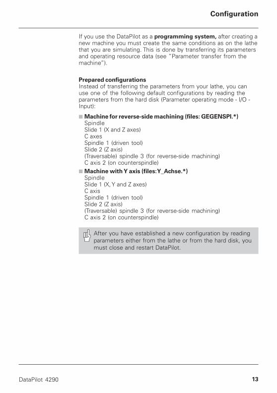
If you use the DataPilot as a programming system, after creating anew machine you must create the same conditions as on the lathethat you are simulating. This is done by transferring its parametersand operating resource data (see ”Parameter transfer from themachine”).
Prepared configurationsInstead of transferring the parameters from your lathe, you canuse one of the following default configurations by reading theparameters from the hard disk (Parameter operating mode - I/O -Input):
■ Machine for reverse-side machining (files: GEGENSPI.*)SpindleSlide 1 (X and Z axes)C axesSpindle 1 (driven tool)Slide 2 (Z axis)(Traversable) spindle 3 (for reverse-side machining)C axis 2 (on counterspindle)
■ Machine with Y axis (files: Y_Achse.*)SpindleSlide 1 (X, Y and Z axes)C axisSpindle 1 (driven tool)Slide 2 (Z axis)(Traversable) spindle 3 (for reverse-side machining)C axis 2 (on counterspindle)
After you have established a new configuration by readingparameters either from the lathe or from the hard disk, youmust close and restart DataPilot.
14 HEIDENHAIN
Starting / Exiting DataPilot
How to Use DataPilot
Starting/exiting DataPilot
To start DataPilot:
Double-click the ”DataPilot 4290 V6.4” icon or select the”DataPilot 4290 V6.4” menu item.Press the ”Num Lock” key to activate the numerical keypad.
After you have started DataPilot, the same machine is active aswhen the program was last exited.
All further functions are the same as for the CNC PILOT 4290.
The numerical lock must be active because the menu itemsare selected from the numeric keypad.
To exit DataPilot:
Click the Exit icon at the upper right in the DataPilot window (thenormal WINDOWS procedure).If DataPilot uses the entire screen, select the ”Exit DataPilot”menu item (in the Machine menu) or press ALT+F4 at theoperating mode level.
• Remember to save your new or edited programs, contourdescriptions, etc. before you exit DataPilot.
• Changes to parameters or to operating resource data arestored as soon as the dialog box is closed.
Keyboard
DataPilot is operated through function keys and numerical keys ofthe PC keyboard. The table on the following page shows theassignment of CNC PILOT 4290 keys to the keys of the PC keyboard.The CNC PILOT 4290 keyboard is illustrated just below it.
DataPilot 4290 15
How to Use DataPilot 4290
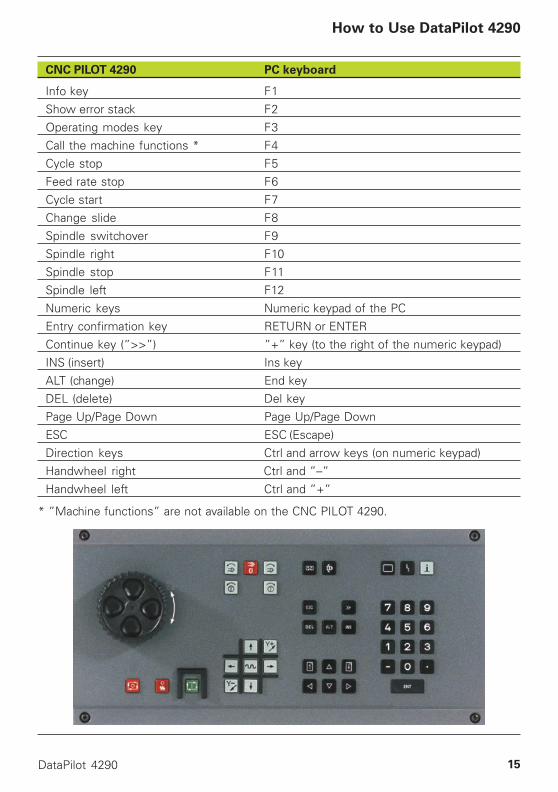
CNC PILOT 4290 PC keyboard
Info key F1
Show error stack F2
Operating modes key F3
Call the machine functions * F4
Cycle stop F5
Feed rate stop F6
Cycle start F7
Change slide F8
Spindle switchover F9Spindle right F10
Spindle stop F11
Spindle left F12
Numeric keys Numeric keypad of the PC
Entry confirmation key RETURN or ENTER
Continue key (”>>”) ”+” key (to the right of the numeric keypad)
INS (insert) Ins key
ALT (change) End keyDEL (delete) Del key
Page Up/Page Down Page Up/Page Down
ESC ESC (Escape)
Direction keys Ctrl and arrow keys (on numeric keypad)
Handwheel right Ctrl and ”–”
Handwheel left Ctrl and ”+”
* ”Machine functions” are not available on the CNC PILOT 4290.
16 HEIDENHAIN
DataPilot Functions
Changing the conversational language
To change the conversational language:
Log on as the ”System Manager.”Select ”Sys.Srv. (System Service) – Language switching” (Ser-vice mode).In the ”Language switching” dialog box, select the newconversational language and press RETURN.Exit and restart DataPilot for the selected conversationallanguage to become effective.
The language changes apply only for the active machine.
Operating resource data
The DataPilot installation program saves examples of operatingresource data on the hard disk. The same resource data is savedfor the DataPilot machine ”EXAMPLE.”
If you create another machine, it will contain no operating resourcedata. However, you can transfer the operating resource data fromthe hard disk (”Parameter mode – I/O – Input”) and adapt it to yourrequirements.
Per machine, DataPilot manages:
■ Up to 512 tool data■ Up to 256 chucking equipment data■ Cutting values for up to 64 cutting materials and 128 workpiece
materials
Operating resource files on the hard disk:
■ ”BSPWZDRE” (example data for turning tools)■ ”BSPWZBOR” (example data for drilling and boring tools)■ ”BSPWZFRA” (example data for milling tools)■ ”BSPASPM” (example data for chucking equipment)■ ”BSPTECNO” (example data for cutting values)

DataPilot 4290 17
Tables for tools and chucking equipment
With TURN PLUS programs you can define by parameter whetherthe tool and chucking equipment tables will be accessible. DINPLUS programs access the tool and chucking equipment table ifthe turret and chucking equipment assignment is not defined inthe part program.
The tool and chucking equipment table is created and edited in theMachine operating mode under ”Setup - Tool list” with thefollowing functions:
■ Compile list – shows all of the tools defined for this tool holder.You can:• Add further tools (Insert key)• Delete tools (Delete key)• Overwrite entered tools (Insert key)• Reposition tools (ALT or END key)
■ Compare list – compares the tool assignment of the mostrecently compiled NC program with the valid tool list.Differences in position are highlighted. You can:• Perform a ”nominal-actual comparison” of highlighted tools(Insert key). The nominal data of the tool are displayed and canbe accepted if desired.• Delete tools (Delete key)• Reposition tools (ALT or END key)
■ Accept list – transfers the tool assignment of the most recentlycompiled part program. If a turret pocket has no tool under thenew assignment, the old entry remains and is highlighted.
If you use DataPilot in the ”programming system” variant:• The tool table is created during simulation ”with K-pro-
gram generation.”• The name of the part program last compiled with the ”K-
program generation” is shown in the uppermost line ofthe screen.
• If DataPilot is configured for more than one slide, themenu item ”$” will appear in the horizontal menu of theMachine mode. You can use the menu item ”$” to switchto the next respective slide/tool carrier.
DataPilot Functions

18 HEIDENHAIN
DataPilot Functions
Graphic simulation
With DataPilot you can achieve the same results as with the targetmachine, provided that the identical parameter settings andoperating resource data are available.
Time calculationDuring graphic simulation, DataPilot calculates the operating time.This calculation includes the total time, the times the tools are inuse, and the machining and idle-machine times.
You can enter the times required for executing the switchingcommands in control parameters 20 and 21.
Programming variablesDataPilot provides display and debug functions for the simulationof NC part program variables. This enables you to reproduceexternal events so that DataPilot can check all program branches(”Debug” is the step-by-step checking of program execution withthe possibility of viewing the contents of variables).
DataPilot 4290 19
DataPilot Functions
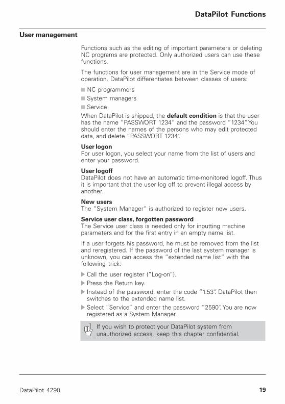
User management
Functions such as the editing of important parameters or deletingNC programs are protected. Only authorized users can use thesefunctions.
The functions for user management are in the Service mode ofoperation. DataPilot differentiates between classes of users:
■ NC programmers■ System managers■ ServiceWhen DataPilot is shipped, the default condition is that the userhas the name ”PASSWORT 1234” and the password ”1234”. Youshould enter the names of the persons who may edit protecteddata, and delete ”PASSWORT 1234”.
User logonFor user logon, you select your name from the list of users andenter your password.
User logoffDataPilot does not have an automatic time-monitored logoff. Thusit is important that the user log off to prevent illegal access byanother.
New usersThe ”System Manager” is authorized to register new users.
Service user class, forgotten passwordThe Service user class is needed only for inputting machineparameters and for the first entry in an empty name list.
If a user forgets his password, he must be removed from the listand reregistered. If the password of the last system manager isunknown, you can access the ”extended name list” with thefollowing trick:
Call the user register (”Log-on”).Press the Return key.Instead of the password, enter the code ”1.53”. DataPilot thenswitches to the extended name list.Select ”Service” and enter the password ”2590”. You are nowregistered as a System Manager.
If you wish to protect your DataPilot system fromunauthorized access, keep this chapter confidential.

20 HEIDENHAIN
DataPilot Functions
Multi-machine organization
The selected ”DataPilot machine” is shown in the uppermost lineof the screen.
Functions for multi-machine managementWith the F4 key (PC keyboard) you can switch to the ”machinefunctions.” You choose from the following functions:
■ Change machineDataPilot displays all available machines in a list box. Select thedesired ”DataPilot machine” and press the Return key. Thisprocess takes a few seconds.
■ Machine organization
• Create machineIn the ”Set up machine” dialog box, you enter the name of thenew machine and select the configuration and variant (see:DataPilot Configuration). This process takes a few seconds.• Delete machineThe ”Delete machine” function erases all existing programs,parameters, and operating resource data.You can call this function only with a ”System Manager”authorization (see: ”User management”).• Rename machineWith the ”Rename machine” function, you can change the nameof an existing ”DataPilot machine.” Select the respectivemachine and enter the new name. (You cannot rename theactive machine.)• Change variantUse this function to define whether you will be using DataPilotas a ”programming system” or ”complete control” (see:DataPilot configuration).
DataPilot 4290 21
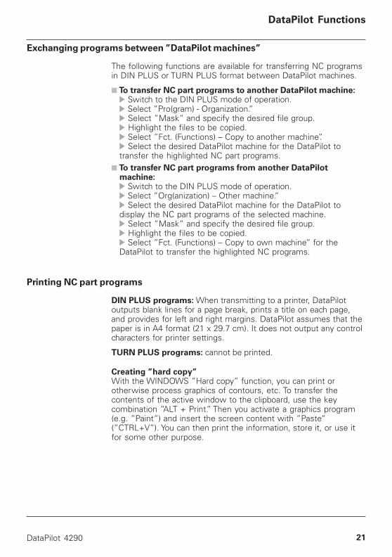
Exchanging programs between ”DataPilot machines”
The following functions are available for transferring NC programsin DIN PLUS or TURN PLUS format between DataPilot machines.
■ To transfer NC part programs to another DataPilot machine: Switch to the DIN PLUS mode of operation. Select ”Pro(gram) - Organization.” Select ”Mask” and specify the desired file group. Highlight the files to be copied. Select ”Fct. (Functions) – Copy to another machine”. Select the desired DataPilot machine for the DataPilot to
transfer the highlighted NC part programs.■ To transfer NC part programs from another DataPilot
machine: Switch to the DIN PLUS mode of operation. Select ”Org(anization) – Other machine.” Select the desired DataPilot machine for the DataPilot to
display the NC part programs of the selected machine. Select ”Mask” and specify the desired file group. Highlight the files to be copied. Select ”Fct. (Functions) – Copy to own machine” for the
DataPilot to transfer the highlighted NC programs.
Printing NC part programs
DIN PLUS programs: When transmitting to a printer, DataPilotoutputs blank lines for a page break, prints a title on each page,and provides for left and right margins. DataPilot assumes that thepaper is in A4 format (21 x 29.7 cm). It does not output any controlcharacters for printer settings.
TURN PLUS programs: cannot be printed.
Creating ”hard copy”With the WINDOWS ”Hard copy” function, you can print orotherwise process graphics of contours, etc. To transfer thecontents of the active window to the clipboard, use the keycombination ”ALT + Print.” Then you activate a graphics program(e.g. ”Paint”) and insert the screen content with ”Paste”(”CTRL+V”). You can then print the information, store it, or use itfor some other purpose.
DataPilot Functions
22 HEIDENHAIN
Data Exchange
Data Exchange
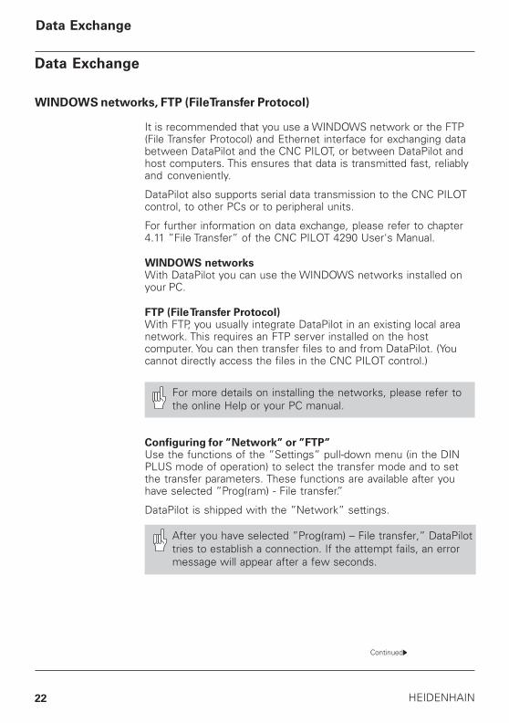
WINDOWS networks, FTP (File Transfer Protocol)
It is recommended that you use a WINDOWS network or the FTP(File Transfer Protocol) and Ethernet interface for exchanging databetween DataPilot and the CNC PILOT, or between DataPilot andhost computers. This ensures that data is transmitted fast, reliablyand conveniently.
DataPilot also supports serial data transmission to the CNC PILOTcontrol, to other PCs or to peripheral units.
For further information on data exchange, please refer to chapter4.11 ”File Transfer” of the CNC PILOT 4290 User's Manual.
WINDOWS networksWith DataPilot you can use the WINDOWS networks installed onyour PC.
FTP (File Transfer Protocol)With FTP, you usually integrate DataPilot in an existing local areanetwork. This requires an FTP server installed on the hostcomputer. You can then transfer files to and from DataPilot. (Youcannot directly access the files in the CNC PILOT control.)
For more details on installing the networks, please refer tothe online Help or your PC manual.
Configuring for ”Network” or ”FTP”Use the functions of the ”Settings” pull-down menu (in the DINPLUS mode of operation) to select the transfer mode and to setthe transfer parameters. These functions are available after youhave selected ”Prog(ram) - File transfer.”
DataPilot is shipped with the ”Network” settings.
After you have selected ”Prog(ram) – File transfer,” DataPilottries to establish a connection. If the attempt fails, an errormessage will appear after a few seconds.
Continued
DataPilot 4290 23
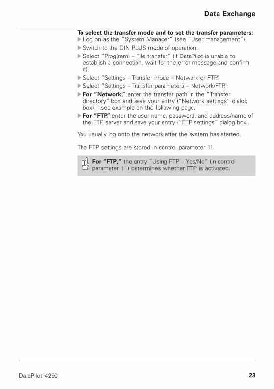
To select the transfer mode and to set the transfer parameters:Log on as the ”System Manager” (see ”User management”).Switch to the DIN PLUS mode of operation.Select ”Prog(ram) – File transfer” (if DataPilot is unable toestablish a connection, wait for the error message and confirmit).Select ”Settings – Transfer mode – Network or FTP.”Select ”Settings – Transfer parameters – Network/FTP.”For ”Network,” enter the transfer path in the ”Transferdirectory” box and save your entry (”Network settings” dialogbox) – see example on the following page.For ”FTP,” enter the user name, password, and address/name ofthe FTP server and save your entry (”FTP settings” dialog box).
You usually log onto the network after the system has started.
The FTP settings are stored in control parameter 11.
For ”FTP,” the entry ”Using FTP – Yes/No” (in controlparameter 11) determines whether FTP is activated.
Data Exchange

24 HEIDENHAIN
Note on connecting DataPilot with CNC PILOT 4290
If you want to directly connect a DataPilot PC with a CNC PILOTcontrol, use a twisted-pair network cable. The control runs on theWINDOWS 98 operating system. When DataPilot is shipped, theNetBEUI and TCP/IP protocols are installed. The workgroup”HNH” is entered and TCP/IP is configured for automatic addressassignment via DHCP. The computer name, ”CNC_PILOT_xxxx,” isgenerated automatically (xxxx is a 4-digit hexadecimal number).You will find information on the computer name (host name) andIP address in the system information (”Diagnosis – Controls –Hardware – System info” in the Service mode of operation). Pleasenote: The ”_” character is displayed as ”-”.
The configuration on the basis of the ”NetBEUI” network protocolis described below. As an alternative, you can use the commonWINDOWS network protocols.
To configure the network:DataPilot PC: Under Network Properties, activate the NetBEUIprotocol.DataPilot PC: Select the same workgroup as in the control.If the DataPilot PC uses the WINDOWS 2000 or XP operatingsystem:■ DataPilot PC: Register the user of the CNC PILOT control in theuser management.■ CNC PILOT control: Under Network Properties, set PrimaryNetwork Logon to ”Client for Microsoft Networks” (see User'sManual ”4.11.4 Configuring for Data Transfer”).
DataPilot 4290 25
Data Exchange
Sharing on the DataPilot PC
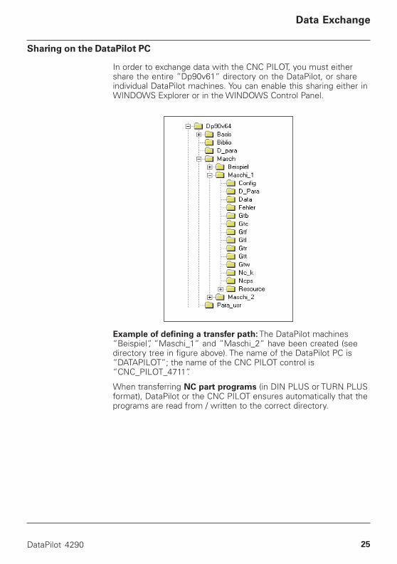
In order to exchange data with the CNC PILOT, you must eithershare the entire ”Dp90v61” directory on the DataPilot, or shareindividual DataPilot machines. You can enable this sharing either inWINDOWS Explorer or in the WINDOWS Control Panel.
Example of defining a transfer path: The DataPilot machines”Beispiel”, ”Maschi_1” and ”Maschi_2” have been created (seedirectory tree in figure above). The name of the DataPilot PC is”DATAPILOT”; the name of the CNC PILOT control is”CNC_PILOT_4711”.
When transferring NC part programs (in DIN PLUS or TURN PLUSformat), DataPilot or the CNC PILOT ensures automatically that theprograms are read from / written to the correct directory.
26 HEIDENHAIN
Entry for the transfer path:
■ On the CNC PILOT control (the entire ”Dp90v64” is beingshared as ”Dp90v64”):\\DATAPILOT\Dp90v64\Masch\Maschi_1
■ On the DataPilot PC:\\CNC_PILOT_4711
When you exchange data with other systems (not DataPilotor CNC PILOT), the last part of the transfer path is expectedor automatically supplied.
Transferring NC part programs
After you have selected ”Program – File transfer” (in DIN PLUSmode), DataPilot displays its own directory in a window to the leftand the directory of the partner in a window to the right.
To change the partner (for ”Network”), edit the entry in ”Trans-fer directory” (”Settings..” dialog box).
To change the file group, edit the entry in ”Mask.”
Data Exchange
DataPilot 4290 27
Transferring parameters from the machine
The CNC PILOT control saves parameters and operating resourcedata in an ”internal” format. If you wish to transfer data from theCNC PILOT to DataPilot, the data must be converted into ASCIIformat and entered in the ”Para_usr” directory before beingtransmitted. The data is read from the ”Para_usr” directory inDataPilot and reconverted (post-processing).
To transfer parameters and operating resource data:
Transfer directory (On CNC PILOT) select the directory fortransferring parameters or operating resource data (the”Para_usr” directory exists only once):\\DATAPILOT\Dp90v64(the entire ”Dp90v64” directory is being shared as ”DP90v64”).Logon (on DataPilot) in the ”Service” user class (see ”Usermanagement”).Prepare the CNC PILOT by selecting ”Parameter output – Target:Hard disk” (Parameter mode: ”I/O – ...”).Transfer the data from the CNC PILOT to DataPilot.Post-process the data on DataPilot by selecting ”Parameterinput – Source of input: Hard disk” (Parameter mode: ”I/O – In-put”).After all parameters/operating resource data have beentransferred, reset theTransfer directory (on CNC PILOT) to NC program transfer.
If you are using DataPilot as a programming system, transfer thefollowing parameters and operating resource data from the targetmachine.
■ Tools■ Chucking equipment■ Technology data■ Machine parameters■ Control parameters (except for parameters 11 and 48)■ Current machining parameters■ Fixed word lists
Data Exchange
28 HEIDENHAIN
Serial data transfer
If you wish to transfer data serially, you must ensure that bothcommunication partners use identical interface parameters. Youcan exchange data with a CNC PILOT control or with otherperipheral units. The maximum transmission rate is 38.4 kilobaud(see ”Serial interface parameters”).
NC program transferNC programs in DIN PLUS format, TURN PLUS workpiecedescriptions, and TURN PLUS working plan definitions are alltransferred in the organization module of the DIN PLUS editor(DIN PLUS editor – ”Prog(ram) – Organization”).
Please note that:■ After calling External output specify the ”Target of output.” If
you select ”External”, ”DP/Machine” or ”Printer,” the interfacesconfigured in control parameter 40 become effective (see”Special Parameters for DataPilot”).
■ After calling External input specify the ”Source of input.” If youselect ”External” or ”DP/Machine,” the interfaces configured incontrol parameter 40 become effective (see ”Special Parame-ters for DataPilot”).DataPilot will recognize automatically whether a DIN/ISO mainprogram, DIN/ISO subprogram or TURN PLUS program istransferred. If an NC part program with the same name alreadyexists on DataPilot, DataPilot will ask whether you want tooverwrite it.
Data Exchange
DataPilot 4290 29
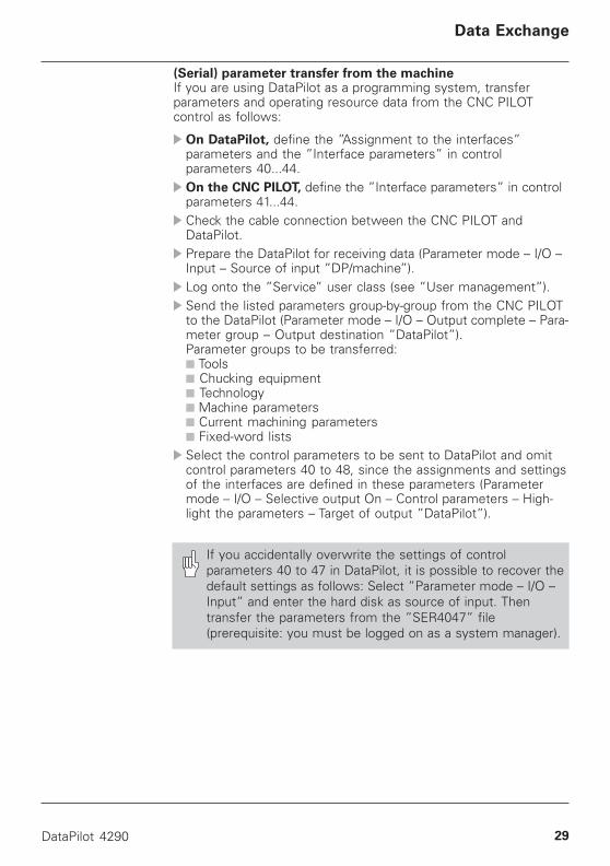
(Serial) parameter transfer from the machineIf you are using DataPilot as a programming system, transferparameters and operating resource data from the CNC PILOTcontrol as follows:
On DataPilot, define the ”Assignment to the interfaces”parameters and the ”Interface parameters” in controlparameters 40...44.On the CNC PILOT, define the ”Interface parameters” in controlparameters 41...44.Check the cable connection between the CNC PILOT andDataPilot.Prepare the DataPilot for receiving data (Parameter mode – I/O –Input – Source of input ”DP/machine”).Log onto the ”Service” user class (see ”User management”).Send the listed parameters group-by-group from the CNC PILOTto the DataPilot (Parameter mode – I/O – Output complete – Para-meter group – Output destination ”DataPilot”).Parameter groups to be transferred:■ Tools■ Chucking equipment■ Technology■ Machine parameters■ Current machining parameters■ Fixed-word listsSelect the control parameters to be sent to DataPilot and omitcontrol parameters 40 to 48, since the assignments and settingsof the interfaces are defined in these parameters (Parametermode – I/O – Selective output On – Control parameters – High-light the parameters – Target of output ”DataPilot”).
If you accidentally overwrite the settings of controlparameters 40 to 47 in DataPilot, it is possible to recover thedefault settings as follows: Select ”Parameter mode – I/O –Input” and enter the hard disk as source of input. Thentransfer the parameters from the ”SER4047” file(prerequisite: you must be logged on as a system manager).
Data Exchange
30 HEIDENHAIN
Special Parameters
Special Parameters for DataPilot
The following control parameters in DataPilot are different fromthose in the CNC PILOT control:
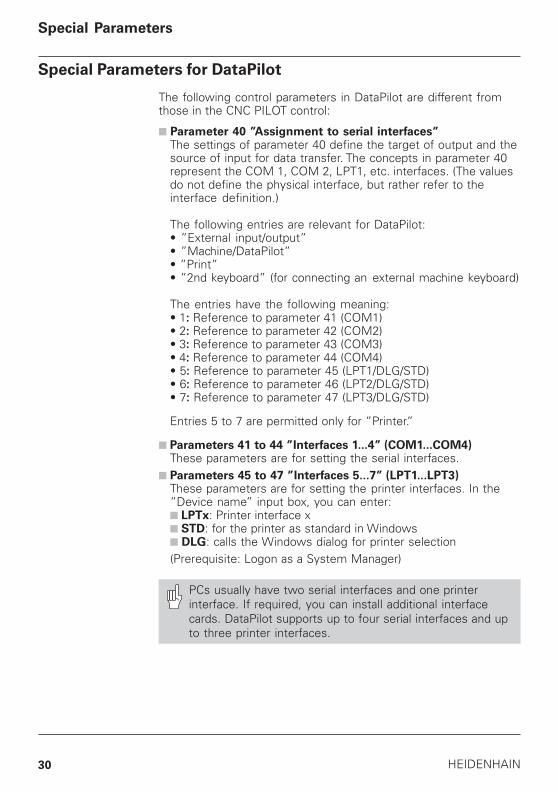
■ Parameter 40 ”Assignment to serial interfaces”The settings of parameter 40 define the target of output and thesource of input for data transfer. The concepts in parameter 40represent the COM 1, COM 2, LPT1, etc. interfaces. (The valuesdo not define the physical interface, but rather refer to theinterface definition.)
The following entries are relevant for DataPilot:• ”External input/output”• ”Machine/DataPilot”• ”Print”• ”2nd keyboard” (for connecting an external machine keyboard)
The entries have the following meaning:• 1: Reference to parameter 41 (COM1)• 2: Reference to parameter 42 (COM2)• 3: Reference to parameter 43 (COM3)• 4: Reference to parameter 44 (COM4)• 5: Reference to parameter 45 (LPT1/DLG/STD)• 6: Reference to parameter 46 (LPT2/DLG/STD)• 7: Reference to parameter 47 (LPT3/DLG/STD)
Entries 5 to 7 are permitted only for ”Printer.”
■ Parameters 41 to 44 ”Interfaces 1...4” (COM1...COM4)These parameters are for setting the serial interfaces.
■ Parameters 45 to 47 ”Interfaces 5...7” (LPT1...LPT3)These parameters are for setting the printer interfaces. In the”Device name” input box, you can enter:■ LPTx: Printer interface x■ STD: for the printer as standard in Windows■ DLG: calls the Windows dialog for printer selection(Prerequisite: Logon as a System Manager)
PCs usually have two serial interfaces and one printerinterface. If required, you can install additional interfacecards. DataPilot supports up to four serial interfaces and upto three printer interfaces.
DataPilot 4290 31
Special Parameters
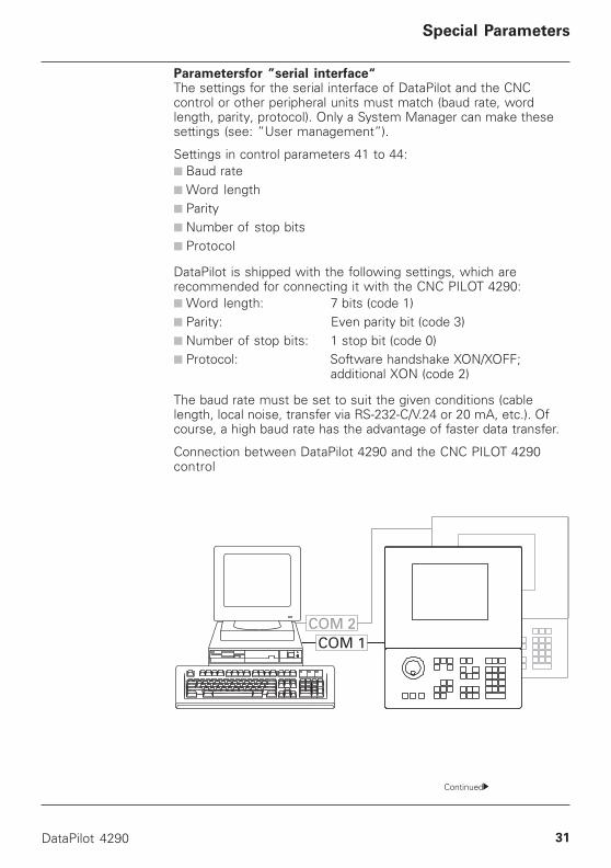
Parametersfor ”serial interface“The settings for the serial interface of DataPilot and the CNCcontrol or other peripheral units must match (baud rate, wordlength, parity, protocol). Only a System Manager can make thesesettings (see: ”User management”).
Settings in control parameters 41 to 44:■ Baud rate■ Word length■ Parity■ Number of stop bits■ Protocol
DataPilot is shipped with the following settings, which arerecommended for connecting it with the CNC PILOT 4290:■ Word length: 7 bits (code 1)■ Parity: Even parity bit (code 3)■ Number of stop bits: 1 stop bit (code 0)■ Protocol: Software handshake XON/XOFF;
additional XON (code 2)
The baud rate must be set to suit the given conditions (cablelength, local noise, transfer via RS-232-C/V.24 or 20 mA, etc.). Ofcourse, a high baud rate has the advantage of faster data transfer.
Connection between DataPilot 4290 and the CNC PILOT 4290control
Continued
32 HEIDENHAIN
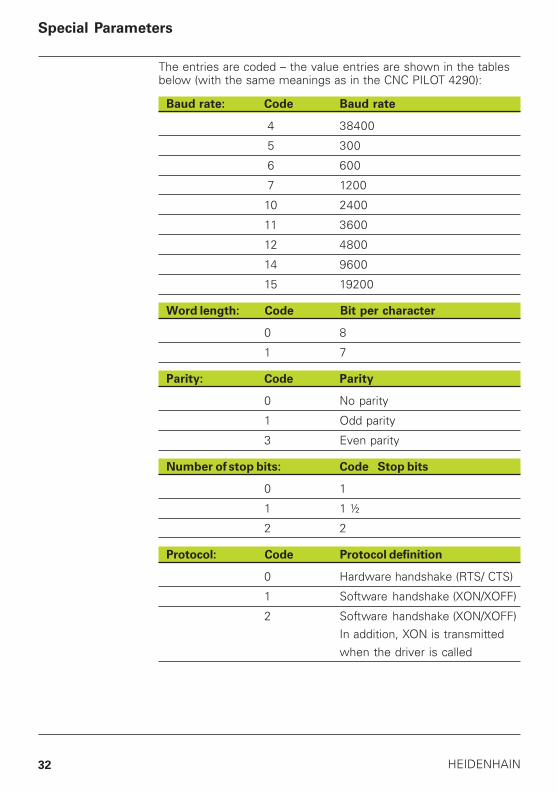
The entries are coded – the value entries are shown in the tablesbelow (with the same meanings as in the CNC PILOT 4290):
Baud rate: Code Baud rate
4 38400
5 300
6 600
7 1200
10 2400
11 3600
12 4800
14 9600
15 19200
Word length: Code Bit per character
0 8
1 7
Parity: Code Parity
0 No parity
1 Odd parity
3 Even parity
Number of stop bits: Code Stop bits
0 1
1 1 ½
2 2
Protocol: Code Protocol definition
0 Hardware handshake (RTS/ CTS)
1 Software handshake (XON/XOFF)
2 Software handshake (XON/XOFF)In addition, XON is transmittedwhen the driver is called
Special Parameters
DataPilot 4290 33
Deleting parametersIf you transfer parameters from the lathe or the disk, existingparameters are overwritten, and any new parameters are added. Ifyou wish to delete parameters, read the ”RESET” parameter file(group: machine parameters) from the hard disk and then transferthe desired configuration.
Additional parameter organizationFor system and service personnel: It is possible to save individualparameters or parameter groups on the hard disk. These files arestored in the ”PARA_USR” directory – they are not assigned to aspecific machine.
This method allows you to manage the settings of differentmachines, tool blocks, cutting data, and the machining parametersof different part groups, etc.
Special Parameters
34 HEIDENHAIN
Data Backup
The DataPilot software does not change after installation. There isno need to save program files containing current information. If forany reason the program is damaged on the PC, you can simplyreinstall DataPilot and continue working.
However, you should make regular backup copies of your NC partprograms, operating resource data, and parameter settings usingthe normal WINDOWS commands. The NC part programs,operating resource data, and parameter settings are located in thesubdirectories of ”Masch” and in the ”PARA_USR” directory.
DataPilot directoriesDuring installation, you must indicate the drive on which DataPilotis to be stored. The DataPilot installation program saves alldirectories under the ”Dp90v61” directory.
Directories with NC part programs, parameters, or operatingresource data:■ NCPS: NC main and subprograms in DIN PLUS format■ NC_K: NC basic programs (see: ”Simulation – Generation of
basic programs”)■ GTR: Workpiece blank descriptions (TURN PLUS format)■ GTF: Finished part descriptions (TURN PLUS format)■ GTW: Workpiece blank and finished part descriptions (TURN
PLUS format)■ GTB: Working plans for machining the workpieces (TURN PLUS
format)■ GTC: Workpiece blank and finished part descriptions as well as
working plans for the workpieces (TURN PLUS format)■ GTT: Individual contour trains (”free contours” library) – (TURN
PLUS format)■ GTL: Turret lists – (TURN PLUS format)■ PARA_USR: Parameter and operating resource files (in ASCII
format) for data exchange with other systems and for your ownorganization. The ”PARA_USR” directory exists only once in thesystem.
Data Backup, DataPilot Directories
DataPilot 4290 35
Structure of NC Part Programs in DIN PLUS Format
Character set, special characters, structure of NC blocks■ DIN PLUS format uses the ASCII character set, i.e. no characters
with ASCII codes greater than 127 characters are permitted.■ The end of a line is marked with ”CR” and ”LF” (hexadecimal
0D, 0A).■ Control characters other than ”CR” and ”LF” are not permitted.
File structure of NC part programs■ The first line begins with a % character followed by the program
name with the extension ”*.nc” for main programs, or ”*.ncs”for subprograms. This line must exist even though it is notdisplayed in the DIN PLUS editor!
■ Before the first NC block containing G commands, the ”section”(ROHTEIL [BLANK], FERTIGTEIL [FINISHED PART] or BEARBEI-TUNG [MACHINING]) must be defined.
■ The program must contain the words BEARBEITUNG[MACHINING] and ENDE [END].
■ Comments are placed in brackets, i.e., [ ].
Additional control characters for transfer via serial interface■ The file end is marked with ”~” (hexadecimal 7E).■ If more than one NC part program is being transferred, the ”~”
at the end of the NC part program is followed immediately bythe ”%” of the next program.
■ The ”EOT” character (hexadecimal 04) means End Of Transfer.
Structure of NC Part Programs
36 HEIDENHAIN
Cable Assembly
Cable Assembly
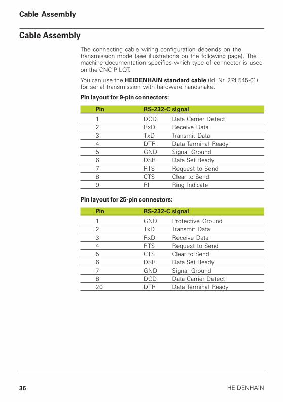
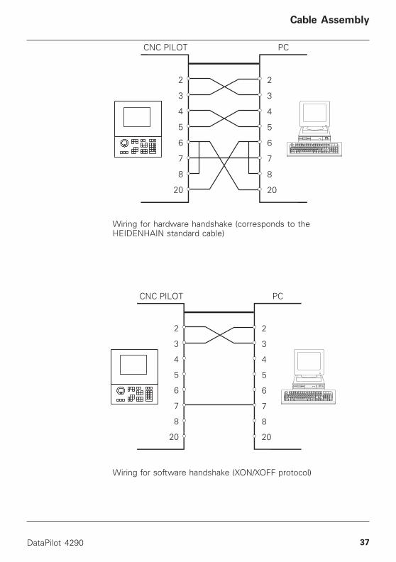
The connecting cable wiring configuration depends on thetransmission mode (see illustrations on the following page). Themachine documentation specifies which type of connector is usedon the CNC PILOT.
You can use the HEIDENHAIN standard cable (Id. Nr. 274 545-01)for serial transmission with hardware handshake.
Pin layout for 9-pin connectors:
Pin RS-232-C signal
1 DCD Data Carrier Detect2 RxD Receive Data3 TxD Transmit Data4 DTR Data Terminal Ready5 GND Signal Ground6 DSR Data Set Ready7 RTS Request to Send8 CTS Clear to Send9 RI Ring Indicate
Pin layout for 25-pin connectors:
Pin RS-232-C signal
1 GND Protective Ground2 TxD Transmit Data3 RxD Receive Data4 RTS Request to Send5 CTS Clear to Send6 DSR Data Set Ready7 GND Signal Ground8 DCD Data Carrier Detect20 DTR Data Terminal Ready
DataPilot 4290 37
Wiring for software handshake (XON/XOFF protocol)
Wiring for hardware handshake (corresponds to theHEIDENHAIN standard cable)
Cable Assembly
38 HEIDENHAIN
Example Programs
Example Programs
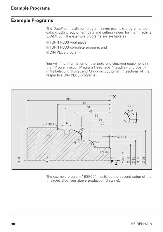
The DataPilot installation program saves example programs, tooldata, chucking equipment data and cutting values for the ”machineEXAMPLE.” The example programs are available as
■ TURN PLUS workpiece■ TURN PLUS complete program, and■ DIN PLUS program.
You will find information on the tools and chucking equipment inthe ”Programmkopf [Program Head] and ”Revolver- und Spann-mittelbelegung [Turret and Chucking Equipment]” sections of therespective DIN PLUS programs.
The example program ”BSP00” machines the second setup of thethreaded stud (see above production drawing).
DataPilot 4290 39
Example Programs
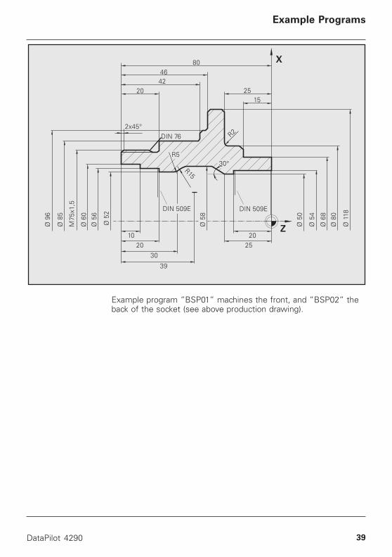
Example program ”BSP01” machines the front, and ”BSP02” theback of the socket (see above production drawing).
40 HEIDENHAIN
Example Programs
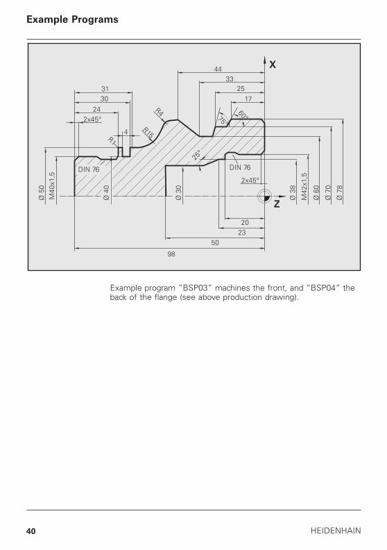
Example program ”BSP03” machines the front, and ”BSP04” theback of the flange (see above production drawing).
DataPilot 4290 41
B
Baud rate 31, 32
C
Cable assembly 36Character set 35Chucking equipment data 16Chucking equipment table 17Complete control 12Configuration 12Control characters 35Control functions 4Control parameters 30Conversational language 12, 16Conversational languages 4Cutting values 33
D
Data backup 34Data transmission 30, 31Deinstallation 9Demo version 8DIN PLUS format 35DIN PLUS programs 21Directories 34Dongle 6, 9Dongle driver 8Dongle server 10Drive 34
E
Example programs 38Exit 14External machine keyboard 30
F
File structure 35
Index
G
Graphic resolution 7Graphic simulation 18
H
Hard copy 21Hardware prerequisites 5
I
Input/output of NC part programs 28Installation 7Interface parameters 29
K
Keyboard 14, 15
L
Language switchover 16Languages 4Line, end of 35
M
Machine 14, 21Machine, changing 20Machine, creating 20Machine, deleting 20Machine, renaming 20Multi-machine concept 12Multi-machine management 20
N
NC programming 4Network dongle 6Networks 22Numeric lock 14
42 HEIDENHAIN
O
Operating resource data 16Operation 14Output of NC part programs 28
P
Parameter transfer 27, 29Parameters 12, 30, 31, 33Parity 31, 32Password 19Printer 21, 30Printer interfaces 30Program transfer 28Programming system 12, 13Protocol 31, 32
R
Range of application 3Right of usage 5
S
Serial 28Serial interface 30, 31Service enquiries 9Settings 31, 33Simulation 18Software version 9Special characters 35Start DataPilot 14Starting 14Stop bits 31, 32Structure of NC part programs 35
T
Time calculation 18Tool data 16Tool table 17Transmission 35TURN PLUS programs 21
U
User classes 19User logoff 19User logon 19User management 19
V
Variable programming 18Version data 9
W
Word length 31, 32
X
XON/XOFF 31
Y
Y axis 13
Index