Embed Size (px)
Citation preview

User Manual
Vertilon Corporation, 66 Tadmuck Road, Westford, MA 01886 / Tel: (978) 692-7070 / Fax: (978) 692-7010 / www.vertilon.com
DPA201 Two Channel Pulse Analyzer

DPA201 Two Channel Pulse Analyzer
Disclaimer
Vertilon Corporation has made every attempt to ensure that the information in this document is accurate and complete. Vertilon assumes no liability for errors or for any incidental, consequential, indirect, or special damages including, without limitation, loss of use, loss or alteration of data, delays, lost profits or savings, arising from the use of this document or the product which it accompanies.
Vertilon reserves the right to change this product without prior notice. No responsibility is assumed by Vertilon for any infringements of patents or other rights of third parties which may result from its use. No license is granted by implication or otherwise under the patent and proprietary information rights of Vertilon Corporation.
Copyright Information
© 2016 Vertilon Corporation
ALL RIGHTS RESERVED


User Manual
Vertilon Corporation -3- UM6182.1.1.docx
Table of Contents
List of Figures ....................................................................................................................... 5
List of Tables ......................................................................................................................... 6
Product Overview ................................................................................................................. 9
Specifications ...................................................................................................................... 15
Theory of Operation ............................................................................................................ 17
Digital Processing Unit (DPU) Architecture ............................................................. 17Decimator ............................................................................................................... 19Timing Processor .................................................................................................... 20Energy Processor ................................................................................................... 24Event FIFO ............................................................................................................. 26Statistics ................................................................................................................. 26Waveform Multiplexer Module ................................................................................ 26Data Block Builder .................................................................................................. 28
Hardware.............................................................................................................................. 29
Graphical User Interface..................................................................................................... 31
Control .............................................................................................................................. 32Tabs........................................................................................................................ 32Analog I/O ............................................................................................................... 32Digital I/O ................................................................................................................ 33Timing ..................................................................................................................... 34Energy ...................................................................................................... 35Devices .................................................................................................... 35
Acquisition ........................................................................................................................ 36Modes ..................................................................................................................... 36Parameters ............................................................................................................. 37
Run/Stop ........................................................................................................................... 38Run/Stop Controls ................................................................................................. 38
Playback ........................................................................................................................... 39Playback Controls ................................................................................................... 39
Display .............................................................................................................................. 41Oscillogram View .................................................................................................... 41List Mode View ......................................................................................... 42Histogram View ........................................................................................ 43MCS View ................................................................................................ 44
Statistics ........................................................................................................................... 44Reporting Tab ......................................................................................................... 44Setup Tab ............................................................................................................... 46
Pull Down Menus .............................................................................................................. 47File .......................................................................................................................... 47System .................................................................................................................... 48

DPA201 Two Channel Pulse Analyzer
Vertilon Corporation -4- UM6182.1.1.docx
Utilities .................................................................................................................... 49
Log Files .............................................................................................................................. 51
Log File Format ................................................................................................................. 51Identification Text Header ....................................................................................... 52Configuration Table ................................................................................................ 52Data Section ........................................................................................................... 52
Configuration Tables .......................................................................................................... 61
User Configuration Table .................................................................................................. 61Custom Configuration Table ............................................................................................. 65Factory Configuration Table .............................................................................................. 66
Software Interface ............................................................................................................... 69
DLL Function Prototypes .................................................................................................. 69Initialize: .................................................................................................................. 69Close: ...................................................................................................................... 69ControlInterface: ..................................................................................................... 69DataInterface: ......................................................................................................... 70ErrorHandler: .......................................................................................................... 71LVDLLStatus: .......................................................................................................... 71
Error Cluster Initialization .................................................................................................. 71Control Interface Commands ............................................................................................ 71Low Level USB Interface Description ................................................................................ 73
USB Device Defaults .............................................................................................. 73HID Implementation ................................................................................................ 74Report Format (IDs 0x01 and 0x11) ....................................................................... 74Report Format (ID 0x22) ......................................................................................... 75
Appendix A .......................................................................................................................... 77
Optional High Voltage Supplies (HVPS001 / HVPS002 / HVPS701) ................................ 77Cable Handling Notice ...................................................................................................... 77
User Manual
Vertilon Corporation -5- UM6182.1.1.docx
List of Figures
Figure 1: Digital Processing Unit ................................................................................ 18
Figure 2: Decimator Waveforms ................................................................................ 19
Figure 3: Crossover Discriminator Waveforms ........................................................... 21
Figure 4: Constant Fraction Discriminator Waveforms ............................................... 22
Figure 5: Leading Edge Discriminator Waveforms ..................................................... 23
Figure 6: Energy Waveforms ..................................................................................... 25
Figure 7: Waveform Acquisition ................................................................................. 27
Figure 8: DPA201 Front & Rear Panels ..................................................................... 29
Figure 9: Front Panel (Histogram Display) ................................................................. 31
Figure 10: Log File Format ......................................................................................... 51
Figure 11: Descriptor / Payload Sequence ................................................................. 53
Figure 12: Oscillogram Payload Packets ................................................................... 57
Figure 13: List Mode Payload Packets ....................................................................... 58
Figure 14: Histogram Payload Packets ...................................................................... 59
Figure 15: MCS Payload Packets .............................................................................. 60

DPA201 Two Channel Pulse Analyzer
Vertilon Corporation -6- UM6182.1.1.docx
List of Tables
Table 1: Log File (ID Text Header Section) ................................................................ 52
Table 2: Log File (Config Table Section) .................................................................... 52
Table 3: Descriptor Words .......................................................................................... 54
Table 4: SYSCFG Format .......................................................................................... 56
Table 5: Oscillogram PLDDET ................................................................................... 57
Table 6: List Mode PLDDET ....................................................................................... 58
Table 7: Histogram PLDDET ...................................................................................... 59
Table 8: MCS PLDDET .............................................................................................. 60
Table 9: User Configuration Table ............................................................................. 65
Table 10: Custom Configuration Table ....................................................................... 65
Table 11: Factory Configuration Table ....................................................................... 68
Table 12: Control Interface Commands ...................................................................... 73
Table 13: USB Device Details .................................................................................... 73
Table 14: HID Report Descriptions ............................................................................. 74
Table 15: Report Format (IDs 0x01 and 0x11) ........................................................... 74
Table 16: Report Error Codes .................................................................................... 75
Table 17: Report Format (ID 0x22) ............................................................................ 75

User Manual
Vertilon Corporation -7- UM6182.1.1.docx
General Safety Precautions
Warning – High Voltages The Model DPA201 can be configured with optional high voltage power supplies. The DPA201, high voltage cable, and connected devices may be energized with potentially harmful high voltages (up to 2000 Volts) during operation.
Use Proper Power Source The Model DPA201 is supplied with a +5V desktop power source. Use with any power source other than the one supplied may result in damage to the product.
Operate Inputs within Specified Range To avoid electric shock, fire hazard, or damage to the product, do not apply a voltage to any input outside of its specified range.
Electrostatic Discharge Sensitive Electrostatic discharges may result in damage to the DPA201. Follow typical ESD precautions.
Do Not Operate in Wet or Damp Conditions To avoid electric shock or damage to the product, do not operate in wet or damp conditions.
Do Not Operate in Explosive Atmosphere To avoid injury or fire hazard, do not operate in an explosive atmosphere.


User Manual Product Overview
Vertilon Corporation -9- UM6182.1.1.docx
Product Overview
The Vertilon Model DPA201 is a two channel general purpose pulse height / pulse timing analyzer. It is implemented as a stand-alone programmable laboratory instrument with a PC interface that is ideal for use as a pulse height analyzer (MCA), time-to-digital converter (TDC), waveform digitizer, coincidence / anti-coincidence detector, discriminator, particle counter, multichannel scaler (MCS), charge-to-digital converter (QDC), or pulse shape analyzer.
The DPA201 has the capability to operate in four acquisition modes — oscillogram, list mode, histogram, and multichannel scaler (MCS). The standard software package for the DPA201 supports oscillogram mode where the unit operates as a two channel pulse digitizer configurable through the included graphical user interface. This mode is used to capture and stream pulse waveform segments to the GUI for real-time display and logging to the computer. It is extremely useful for setup, diagnostics, and implementing user-defined off-line waveform processing functions. Each input channel consists of a fully programmable timing signal path comprised of noise reduction filters, an arming circuit, and three types of user-selectable discriminators. The timing path generates high resolution timestamps and trigger signals that are used by the energy path in the other acquisition modes. List mode, histogram (MCA) and multichannel scaler (MCS) functionality are available separately through optional software upgrades. In list mode, pulse height signals are processed in the energy path by a moving average noise filter, a trapezoidal shaping filter, a pole-zero compensator, and baseline subtractor. The resulting energy and timestamp data are displayed in the GUI and logged to disk. The system’s playback mode allows log files to be retrieved from disk and played back in the GUI display. Energy and time data can be further processed with the optional histogram and MCS software.
Applications
Waveform Digitizer
Multichannel Analyzer (MCA)
Pulse Height Analyzer (PHA)
Time-to-Digital Converter (TDC)
Coincidence / Anti-Coincidence Detector
Programmable Discriminator
Charge to Digital Converter (QDC)
Single Channel Analyzer (SCA)
Time of Flight
Gated Integration
Particle Counter
Signal Delay
Multichannel Scaler (MCS)
Pulse Shape Analyzer
DPA201 Two Channel Pulse Analyzer
Vertilon Corporation -10- UM6182.1.1.docx
Product Highlights
Oscillogram, List Mode, and Histogram Acquisition Two Independent Processing Channels
500 MHz Waveform Sampling Two Programmable Analog Outputs
Real-Time Display in All Acquisition Modes Front Panel Counting Statistics
High Speed Logging in All Acquisition Modes Easily Configured Using Full Function GUI
Playback of All Log Files Display of Up to Four Oscillogram Waveforms
Selectable Timing / Energy Signals Programmable Time and Energy Filters
Up to Four Lists of Data Selectable Discriminators
Height, Time of Arrival, Delta Time Up to 16K MCA Bins
Programmable Timing / Energy Parameters Time to Digital Conversion
Single/Dual Histogram Display Live Energy/Time Histograms
Region of Interest Cursors Programmable Number of Bins
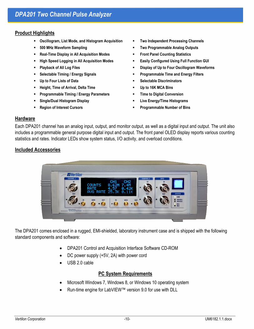
Hardware
Each DPA201 channel has an analog input, output, and monitor output, as well as a digital input and output. The unit also includes a programmable general purpose digital input and output. The front panel OLED display reports various counting statistics and rates. Indicator LEDs show system status, I/O activity, and overload conditions.
Included Accessories
The DPA201 comes enclosed in a rugged, EMI-shielded, laboratory instrument case and is shipped with the following standard components and software:
• DPA201 Control and Acquisition Interface Software CD-ROM
• DC power supply (+5V, 2A) with power cord
• USB 2.0 cable
PC System Requirements
• Microsoft Windows 7, Windows 8, or Windows 10 operating system
• Run-time engine for LabVIEW™ version 9.0 for use with DLL

User Manual Product Overview
Vertilon Corporation -11- UM6182.1.1.docx
Graphical User Interface
The screen shot below shows the main window of the Graphical User Interface (GUI) software included with the DPA201. All control, status, and acquisition functions are executed through this interface.
1. Main Real Time Display Area 6. Digital I/O Parameters
2. Cursor Values 7. Log File Play Back Controls
3. Event Counters & Statistics 8. Timing / Trigger Configuration
4. Acquisition Mode Parameters 9. Energy Parameters
5. Input Configuration 10. Run / Stop Button
1 3
9 106 5
4
8 7
2

DPA201 Two Channel Pulse Analyzer
Vertilon Corporation -12- UM6182.1.1.docx
Software Options
The DPA201 standard software package supports oscillogram acquisition mode with timestamps and count statistics. It includes timing path configuration as well as display, logging, and playback of acquired waveform segments. Various software modules are available to equip the unit with additional functionality as shown in the figure below. Look for the colored symbols in this document to indicate which software modules are required to add the desired functionality.

User Manual Product Overview
Vertilon Corporation -13- UM6182.1.1.docx
Acquisition Modes
The DPA201 includes standard software to support oscillogram acquisition mode. Optional software upgrades are available to add list mode, histogram, and multichannel scaler functionality. The acquisition modes are summarized below.
OSCILLOGRAM
Four CH1 / CH2Waveforms
Input Signal
Timing Filter Output
Trapezoidal Filter Output
Pole-Zero Compensator
LIST MODE
CH1 / CH2 Pulse Heights
CH1 / CH2 Timestamps
HISTOGRAM
MCA Functionality
Dual Histograms
CH1 / CH2 Pulse Heights
CH1 vs CH2 Time Difference
MCS
Multichannel Scaler
Functions
Dual Histograms
Time of Arrival vs Trigger
n n+1 n+2
Tn
En
Tn+1
En+1
Tn+2
En+2
N Cumulative Events
N Cumulative Events
DPA201 Two Channel Pulse Analyzer
Vertilon Corporation -14- UM6182.1.1.docx
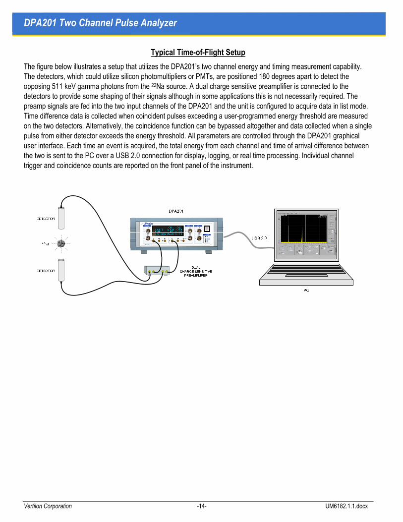
Typical Time-of-Flight Setup
The figure below illustrates a setup that utilizes the DPA201’s two channel energy and timing measurement capability. The detectors, which could utilize silicon photomultipliers or PMTs, are positioned 180 degrees apart to detect the opposing 511 keV gamma photons from the 22Na source. A dual charge sensitive preamplifier is connected to the detectors to provide some shaping of their signals although in some applications this is not necessarily required. The preamp signals are fed into the two input channels of the DPA201 and the unit is configured to acquire data in list mode. Time difference data is collected when coincident pulses exceeding a user-programmed energy threshold are measured on the two detectors. Alternatively, the coincidence function can be bypassed altogether and data collected when a single pulse from either detector exceeds the energy threshold. All parameters are controlled through the DPA201 graphical user interface. Each time an event is acquired, the total energy from each channel and time of arrival difference between the two is sent to the PC over a USB 2.0 connection for display, logging, or real time processing. Individual channel trigger and coincidence counts are reported on the front panel of the instrument.

User Manual Specifications
Vertilon Corporation -15- UM6182.1.1.docx
Specifications
(TA = +25C, unless otherwise noted)
Description Sym Min Typ Max Units Notes
ANALOG INPUT
Voltage Range 3.20
1.60
0.80
0.40
0.20
0.10
V pk-pk
Gain setting #1: gain of 0.125
Gain setting #2: gain of 0.25
Gain setting #3: gain of 0.5
Gain setting #4: gain of 1
Gain setting #5: gain of 2
Gain setting #6: gain of 4
Offset Adjustment Range -2.5 +2.5 V
Input Impedance 50 Ω
ANALOG MONITOR OUTPUT
Gain from ADC Input to Monitor Output 0.50 Into 50 ohms
Offset Adjustment Range -0.5 +0.5 V
Output Impedance 50 Ω
ANALOG OUTPUT
Gain from ADC Input to Monitor Output -1.0 +1.0 V Into 50 ohms
Offset Adjustment Range -1.0 +1.0 V
Output Impedance 50 Ω
ANALOG-TO-DIGITAL CONVERTER (ADC)
Resolution 12 Bits
Sampling Rate Fadc 500 MHz
Sampling Period Tadc 2 nsec
DIGITAL-TO-ANALOG CONVERTER (DAC)
Resolution 14 Bits
Sample Clock Rate 500 MHz
Sample Period 2 nsec
DECIMATOR
Decimator Factor DF 1 32 Actual DF values 1, 2, 4, 8, 16, 32
Decimator Output Sample Period
DF = 1
DF = 2
DF = 4
DF = 8
DF = 16
DF = 32
TS
2
4
8
16
32
64
nsec
Basic reference time period for all timing parameters

DPA201 Two Channel Pulse Analyzer
Vertilon Corporation -16- UM6182.1.1.docx
Description Sym Min Typ Max Units Notes
OSCILLOGRAM
Segment Size 256 2048 samples
Time Period
DF = 1
DF = 32
4.096
131.07 usec
Assumes segment size of 2048.
Segment Delay from Trigger -128 127 samples
Assumes segment size of 2048 and varies with decimation factor (DF).
Sustained Event Rate (Size = 256)
Sustained Event Rate (Size = 2048)
8,000
1,000 1/sec
Average event transfer rate to the host PC.
Segment Storage Capacity (Size = 256)
Segment Storage Capacity (Size = 2048)
256
32 segments
Specifies the number of segments that can be stored in the DPA201 local memory. Important for high peak event rates.
TIMING PARAMETERS
Moving Average Filter Width 0 31 samples
High Pass Differencer 0 31 samples Used as first differencer for crossover discriminator.
Crossover Discriminator 2nd Differencer 0 31 samples
Constant Fraction Discriminator Delay 0 255 samples
Constant Fraction Discriminator Fraction 0.10 0.50 Increments of 0.10 each.
Arming Threshold 0.10 100 % FS Percent of full scale of timing path dynamic range.
Arming Time0 1023 samples
Length of time that trigger path is armed following the signal crossing the arming threshold.
Delay from Zero Crossing 0 2047 samples Delay time from zero crossing to actual trigger generation.
ENERGY PARAMETERS
Trapezoidal Filter Rise Time R 0 63 samples
Trapezoidal Filter Flat Top Time M 0 1023 samples
Pole-Zero Compensation Time 0 4095 samples
Post Moving Average Filter Width 0 31 samples
DIGITAL INPUT
Input Impedance Ω
Logic High Input Level VIH +3.3 V
Logic Low Input Level VIL 0 V
DIGITAL OUTPUT
Output Impedance Ω
Logic High Output Level VOH +3.3 V (IOH = -32mA)
Logic Low Output Level VOL 0 V (IOL = 32mA)
MECHANICAL
Width 250 mm
Height 85 mm
Depth 260 mm

User Manual Theory of Operation
Vertilon Corporation -17- UM6182.1.1.docx
Theory of Operation
The DPA201 utilizes algorithms residing in a high speed FPGA-based Digital Processing Unit (DPU) to extract trigger, energy, and timing information from the input waveform. Virtually all processing functions including signal filtering, trapezoidal shaping, baseline subtraction, pulse pileup elimination, etc. are performed in real time in the digital domain. This architecture allows for enormous flexibility in functionality, ease of configuration programming, and excellent system stability. The only electrical functions performed in the analog domain are gain and offset adjustment of the input signal. Optimum performance is achieved when the input signal is properly positioned within the input range of the high speed digitizer. Once digitized all signal processing and conditioning is done in the digital domain in the DPU.
The DPU operates on very high speed samples of the input waveform. Oversampling of the input waveform affords many advantages over slower sampled systems by shifting more of the processing functions to the digital domain. For example, high frequency noise filtering of the signal is possible because the input pulse waveform is digitized at a rate well above its bandwidth. Additionally, the oversampling of the input waveform allows the DPU to effectively improve the signal amplitude resolution beyond the quantization levels of the sampling ADC. For timing applications, stable sub-nanosecond time stamp resolution is easily achievable.
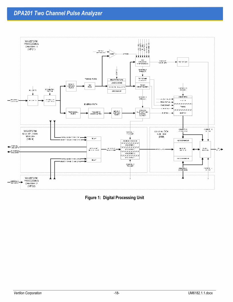
Digital Processing Unit (DPU) Architecture
The DPU shown below is comprised of two identical Waveform Processing Channels (WPCs) connected to a common Waveform Multiplexer Module (WMM) and Data Block Builder (DBB). The WPCs extract the trigger points, calculate timing, and record the energy samples while the WMM in conjunction with the DBB are responsible for waveform accumulation, histogram building, data formatting, and event packet building. All control and status information relating to the two WPCs, WMM, and DBB, is passed through a proprietary hardware interface to the GUI which is used to configure and monitor the status of the DPU.
The two WPCs are identical and have I/O consisting of a 12 bit waveform input and several external digital timing inputs and outputs. A waveform entering the WPC undergoes polarity normalization and sampling decimation if necessary. After the decimator, the waveform is split into two signal processing paths, a timingprocessor path where trigger and timestamps are generated, and an energy processor path where the signal energy level is determined. The two paths operate continuously in real time with the timing processor
determining the trigger point that is used to sample the energy signal in the energy processor. Timing and energy data are only recorded if all conditional triggering criteria (e.g. no pile-up, coincidence, etc.) are met.
Timing data, energy information, and status in each WPC are buffered and accumulated in their respective event FIFOs. The outputs from these FIFOs are continuously streamed to the Data Block Builder while all waveform samples are similarly streamed to the Waveform Multiplexer Module. Collectively the DBB and WMM are used to capture and display the event waveforms, create energy / time lists, and plot energy / time histograms. Additionally, selected waveforms can be delayed and routed by the WMM to the two 14 bit digital to analog converters for diagnostics or connection to external instrumentation.
DPA201 Two Channel Pulse Analyzer
Vertilon Corporation -18- UM6182.1.1.docx
Figure 1: Digital Processing Unit

User Manual Theory of Operation
Vertilon Corporation -19- UM6182.1.1.docx
Decimator
Decimation is used when the expected duration of the input event is long — typically hundreds of times greater than the 2 nsec sampling period (Tadc) of the ADC. By enabling the decimator, longer event lengths can be accommodated by averaging adjacent samples from the ADC into a single sample. The following example illustrates the operation of the decimator with a decimation factor of 2. By averaging every two adjacent samples from the ADC, the decimator output sample period (TS) doubles to 4 nsec. The advantage is that pulse lengths of twice the time compared to undecimated events can be handled by the system.
Figure 2: Decimator Waveforms
INPUTEVENT
Tadc
ADC SAMPLED
EVENT
DECIMATEDEVENT
TS

DPA201 Two Channel Pulse Analyzer
Vertilon Corporation -20- UM6182.1.1.docx
Timing Processor
The main purpose of the DPU timing processor is to generate a precise time reference trigger off of the input pulse. This trigger is then used to sample the energy signal, create a timestamp, determine coincidence / anticoincidence, and count event occurrences. The trigger chain consists of a pre-filter, discriminator, and zero crossing detector (ZCD). The output of the ZCD is the trigger signal. It is fed to the timestamp circuit and energy sampler, as well as other functional blocks that require time synchronization to the input pulse. Precise timestamps are generated by using the trigger signal to sample the discriminator output twice — one just prior to the trigger, and the other just after it. The two samples are then interpolated so that a timestamp is created with resolution considerably better than the sampling period. When operating the DPA201 as a waveform capture instrument, the trigger is used by the Waveform Multiplexer Module to synchronize the storage of a segment of the input pulse, energy trapezoid, and other internal signals. This allows the unit to only collect waveform data when valid triggers are received thus significantly reducing the storage and bandwidth requirements in the host PC.
The diagrams on the following three pages illustrate typical signals found in the timing processor discriminators. As an example, a noisy input waveform is shown as the input to the timing processor. The waveform is for a positive polarity event although a negative polarity event could also easily be accommodated. Noise is reduced on the input signal by a timing filter comprised of a configurable moving average filter and a low cutoff frequency high pass filter. The moving average filter reduces high frequency noise without significantly affecting the rise time of the input waveform, while the high pass filter removes the waveform’s low frequency baseline. The filtered event is passed through one of three discriminators. Depending on the timing requirements, the user can select between a crossover, constant fraction, or leading edge discriminator. The discriminator is followed by a zero crossing detector whose output provides the absolute reference for timing measurements, energy sampling, and other functions relating to the triggering event. Although the discriminator alone provides the timing reference, the actual trigger generation undergoes three phases — arming, trigger, and lockout. Arming of the zero crossing detector occurs when the input to the discriminator crosses a user-defined threshold. If the signal to the arming circuit remains above the arming threshold for a user-defined period, the zero crossing detector becomes enabled and waits for the discriminator signal to cross zero. Once the signal crosses zero and the trigger qualification conditions such as no pile-up, coincidence, etc. are met, the trigger is generated. The
trigger remains active during the lockout period so as to prevent unwanted triggering while the input pulse is still present. This eliminates erroneous triggering due to noise, pile-up, etc. Additionally, programmable hysteresis in the zero crossing detector further reduces noise.

User Manual Theory of Operation
Vertilon Corporation -21- UM6182.1.1.docx
Crossover Discriminator This discriminator is made from two stages of digital differencers. The differencing time parameter is typically set to the rise time of the input pulse and is the same for both the first and second differencer. The differencers, which are equivalent to differentiators in the analog domain, create an output waveform that crosses zero at the pulse peak. Generation of the trigger time reference based on the pulse peak minimizes timing walk due to amplitude variations.
Figure 3: Crossover Discriminator Waveforms
FILTEREDEVENT
Tr
INPUTEVENT
Td
TRIGGER
Tlo
FIRSTDIFFERENCE
SECONDDIFFERENCE
ZEROCROSSING
Varm
TRIGGERARMING
Tarm

DPA201 Two Channel Pulse Analyzer
Vertilon Corporation -22- UM6182.1.1.docx
Constant Fraction Discriminator Two user programmed parameters are required for the constant fraction discriminator, the delay time (D) and fraction (F). This discriminator operates exactly as a conventional analog CFD whereby the delayed and inverted input signal is added to an attenuated version of it. The trigger point is created at the zero crossing of the result.
Figure 4: Constant Fraction Discriminator Waveforms
Tr
Td
TRIGGER
Tlo
ZEROCROSSING
Varm
TRIGGERARMING
Tarm
FILTEREDEVENT
INVERTED /DELAYED
EVENT
Delay = D
ATTENUATEDEVENT
Fraction = F
SUMMEDSIGNAL
INPUTEVENT

User Manual Theory of Operation
Vertilon Corporation -23- UM6182.1.1.docx
Leading Edge Discriminator The leading edge discriminator is the simplest of the three discriminators and is most useful for quickly setting up a system to acquire signals. The voltage threshold (Vth) parameter is the only required user parameter. It is specified as a percentage of the full scale signal range of the Waveform Processing Channel.
Figure 5: Leading Edge Discriminator Waveforms
TRIGGER
Tlo
ZEROCROSSING
Varm
TRIGGERARMING
Tarm
FILTEREDEVENT
INPUTEVENT
0 Volt Baseline
VthTHRESHOLD
SHIFTEDEVENT

DPA201 Two Channel Pulse Analyzer
Vertilon Corporation -24- UM6182.1.1.docx
Energy Processor
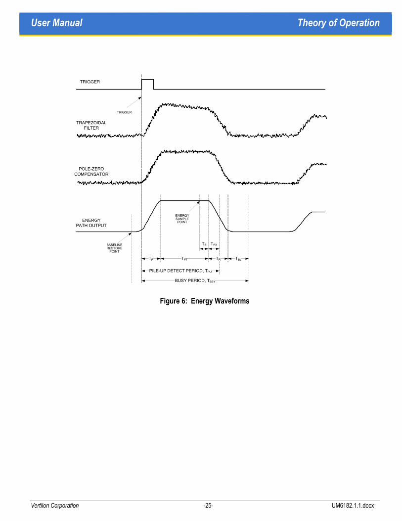
Typical timing parameters for the energy processor are shown in the figure below. The trapezoidal filter, pole-zero compensator, and moving average filter continually process pulse signals in the energy path. Only when a valid trigger signal is received, is the actual energy signal sampled and stored for further processing.
Trapezoidal Filtering This signal shaping function utilizes two user-provided parameters, the trapezoid rise period (TR) and trapezoid flat top period (TFT). The total shaping time is equal to 2TR+TFT and should be selected based on the user’s detector characteristics and event throughput, pile-up rejection, and energy resolution requirements. In general, the flat top period, TFT should be chosen to be slightly greater than the pulse rise time to minimize ballistic deficit effects.
Pole-Zero Compensation The pole-zero compensator cancels the effect of signal decay in the user’s external preamplifier. This parameter is chosen to match the discharge time constant of the charge sensitive preamplifier.
Moving Average Filter This function reduces the high frequency noise on the energy signal before it is sampled.
Raw Energy Sample The optimum point in time to sample the energy signal is at a point just prior to the end of the trapezoid flat top period. This time, referred to as TE, should generally be a small fraction of the flat top time, TF. Generally, one-tenth of the flat top time is usually adequate.
Baseline Subtraction The baseline restore period (TBL) is reserved at the end of the trapezoid for the purpose of sampling the baseline of the next pulse in the energy path. Just prior to the trigger point but during the baseline restore period, a baseline reference of the fully-processed energy signal is taken. This result is stored and subsequently subtracted from the raw energy sample. The effect of reserving this time is that it slightly adds to the busy period (TBSY) of the energy path. The busy period is thus equal to 2TR+TFT+TBL.
Pile-Up Detection Pile-up detection is performed during the pile-up detection period (TPU) in the timing path. The extension period (TPX) is the period of time beyond the end of the trapezoid flat top that is reserved for additional detection of pile-up conditions. The pile-up detection period is equal to TR+TFT+TPX. Depending on the pile-up handling parameters set by the user, pile-ups can be accepted, rejected, counted, or flagged.
User Manual Theory of Operation
Vertilon Corporation -25- UM6182.1.1.docx
Figure 6: Energy Waveforms
TR TRTFT
TRIGGER
ENERGYSAMPLEPOINT
TPXTE
PILE-UP DETECT PERIOD, TPU
TBL
BUSY PERIOD, TBSY
TRIGGER
POLE-ZEROCOMPENSATOR
TRAPEZOIDALFILTER
BASELINERESTORE
POINT
ENERGYPATH OUTPUT

DPA201 Two Channel Pulse Analyzer
Vertilon Corporation -26- UM6182.1.1.docx
Event FIFO
Event-specific data such as timestamps, energy level, trigger conditions, and overload status, are collected in the event FIFO. Each valid trigger produces a dataset that is buffered in the FIFO and read out at the appropriate time by the Data Block Builder. Depending on the DPA201 acquisition mode, the event dataset can be used by the histogrammer, packet builder, or neither. For instance, when histogramming energy levels such as in pulse height analysis applications, only the energy data in the event FIFO is used by the histogrammer — timestamp and trigger conditions are ignored. Conversely, for oscillogram acquisition, virtually all event data is used by the packet builder and none by the histogrammer. The packet builder uses the event-specific dataset to create a descriptor packet that precedes the oscillogram payload. The descriptor and payload together form a data block which is described in more detail in the data block builder section.
Statistics
The statistics functional block keeps track of event rate data such as trigger count, trigger count rate, pile-ups, coincidences, vetoes, overloads, etc. This information is inserted into the descriptor packet of every data block
by the data block builder.
Waveform Multiplexer Module
The WMM is used to select a subset of the various internal waveforms in the Waveform Processing Channelsfor display in the GUI and storage on the host PC. Because of memory and speed limitations in the computer, waveforms are collected in user-programmable fixed size segments. The segment size is typically equal to the pulse length (in time) and consists of an integral number of contiguous samples from the output of the decimator. When a valid trigger is received, a oscillogram is taken and subsequently stored in the memory of the Data Block Builder where it is then assembled into an event packet and transferred to the PC over the USB port. The GUI is used to display the waveform and configure the data logging parameters. By only processing oscillograms from actual valid events, a large reduction in data handling is achievable.
The example on the following page illustrates how oscillograms are extracted from a sequence of three events. The waveform multiplexer in the WMM is used to select an internal waveform for segment acquisition. Although four multiplexing ports are available in the WMM, only two waveforms — the input event and the trapezoidal
energy signal — are shown in the figure. A trigger signal is created by the Waveform Processing Channelcrossover discriminator when its second differencer crosses zero and all triggering criteria is met. For each valid event, the WPC outputs a trigger to the WMM and creates a timestamp, TSTMPn, that is queued in the WPC event FIFO. The trigger initiates the oscillogram acquisition process whereby the WMM selects a segment of length TPL from each of its ports. The actual phasing of each segment relative to the trigger signal is controlled by delay parameter, TnTRIG. This parameter is programmable by the user and unique to each multiplexer port. In the example, T1TRIG is a large negative delay for the input event segment on port 1 and T2TRIG is a small positive delay for the trapezoidal energy segment on port 2. The three segments from port 1 (W1n, W1n+1, W1n+2) and port 2 (W2n, W2n+1, W2n+2) are continuously transferred to the memory array in the Data Block Builder for storage and event building.
The Waveform Multiplexer Module also has the capability to route waveform signals to the DPA201’s two digital-to-analog converters. It can operate in segment mode or continuous mode. In segment mode, any of the delayed oscillograms from the four multiplexer ports can be simultaneously routed to either of the two DACs. This mode is convenient for diagnostics and for setting up waveform acquisition phasing. It is also useful for generating an analog baseline-restored event stream (with trigger references on the digital output port) for connection to other external equipment. Continuous mode allows any internal waveform to be routed with a

User Manual Theory of Operation
Vertilon Corporation -27- UM6182.1.1.docx
programmable delay to either of the two DACs. Since waveforms are continuously streamed in this mode, all events whether valid or not appear on the DAC outputs. While also useful for diagnostics and setup, it can be conveniently utilized as an analog delaying device.
Figure 7: Waveform Acquisition
INPUTEVENT
TRIGGER
SECONDDIFFERENCE
ZEROCROSSING
TPL
ENERGYOUTPUT
W2n W2n+2W2n+1
TSTMPn+1TSTMPn TSTMPn+2
W1n W1n+2W1n+1
T1TRIG
T2TRIG

DPA201 Two Channel Pulse Analyzer
Vertilon Corporation -28- UM6182.1.1.docx
Data Block Builder
The main functional elements in the Data Block Builder are the memory array, histogrammer, and packet builder. Together these units combine statistics and event specific data — such as timestamps, energy, and status — into a larger data block that, depending on the acquisition mode, contains histogram data, oscillograms, and energy / time samples. In general, the data block is comprised of a descriptor packet followed by payload packets. The histogram, waveform, and time-roll acquisition modes of the DPA201 create large amounts of data and require the use of the memory array in the DBB where the payload is accumulated. Conversely, the statistics acquisition mode needs only a small amount of buffering and therefore does not require the memory array. In this mode only a descriptor packet containing statistics and status is included in the data block — no payload packets follow.
Memory Array Real-time streaming data is buffered in the memory array. The array temporarily stores oscillograms and energy / time samples until the packet builder is ready to transfer them to the computer. In the steady-state the average input event rate must be less than the transfer rate to the host PC to prevent events from being dropped. Although the large size of the memory arrayhas no effect on this condition, it does allow for long periods of high peak event rates to be sustained. If the memory array does become full — because either an extended period of high rate events occurred, or because the average input event rate exceeds the transfer rate to the PC — additional events are rejected until the memory array can again accommodate them. The design of the memory array is such that only complete events will be captured with no data fragments. This guarantees that under conditions that would overrun the memory, the only adverse effect would be a gradual reduction in the percentage of input events that are transferred to the computer. In histogram mode, the memory array is used in an altogether different way. Generally there is no need for buffering oscillograms or event energy / time samples because they are not passed to the host PC. Rather the memory array is simply used to hold the bin counts for the event energy / time values. Once the histogramming process is complete — either because the histogram time period or event total has been reached — the count totals in each bin are transferred from the memory array to the computer and then reset to zero.
Histogrammer The histogrammer operates in conjunction with the memory array. It increments (by one) the contents of the memory location that corresponds to the energy / time bin for the current event. In some modes of operation the memory array is partitioned so that multiple histograms can be generated.
Packet Builder All data that is transferred to the PC is passed in the form of data blocks by the packet builder. Data blocks are comprised of a descriptor data packet followed by payload packets. For all acquisition modes, the packet builder assembles the data blocks to include event statistics, event specific data, oscillograms, and histograms.

User Manual Graphical User Interface
Vertilon Corporation -29- UM6182.1.1.docx
Hardware
The photos below show the front and rear panels of the DPA201.
Figure 8: DPA201 Front & Rear Panels
1. Channel 1 Input (SMB): Input to channel 1 from charge sensitive preamp or detector. The adjacent bi-color LED blinks green when the input signal results in an internal trigger to the unit and red if an overload is detected.
2. Channel 1 Monitor (SMB): Monitor output for channel 1 taken at the input to the digitizer. Used for adjusting the signal input range and offset.
3. Channel 1 Output (SMB): Programmable output for channel 1. Used to view intermediate signals from the trigger and energy digital processors. The adjacent LED blinks red when an overload is detected on the output signal.
4. Channel 1 Digital Input (BNC): External digital input for channel 1. Adjacent green LED indicates signal activity.
11
10
2
9 8
1
4
7
6 3
5
1213

DPA201 Two Channel Pulse Analyzer
Vertilon Corporation -30- UM6182.1.1.docx
5. Channel 1 Digital Output (BNC): External digital output for channel 1. Adjacent green LED indicates signal activity.
6. Channel 2 Signal Ports: Analog and digital signals for channel 2. Functionality is identical to channel 1 ports.
7. Front Panel Display: Shows real time count totals and rates for each signal channel.
8. General Purpose Digital Input (BNC): External general purpose digital input. Adjacent green LED indicates signal activity.
9. General Purpose Digital Output (BNC): External general purpose digital output. Adjacent green LED indicates signal activity.
10. Main Power Switch: Main power switch.
11. System Status Indicators: LEDs to show status of system connections and peripherals.
USB: Connection to PC active Device1: External device #1 connected Device2: External device #2 connected HV1: Optional high voltage power supply #1 status HV2: Optional high voltage power supply #2 status
12. USB Port: Connection to USB 2.0 port from computer.
13. Power Input: Power input from included +5V power supply.

User Manual Graphical User Interface
Vertilon Corporation -31- UM6182.1.1.docx
Graphical User Interface
Running ControlInterface.exe will open the main window (front panel) of the Control and Acquisition Interface Software. The front panel is generally for display and control of the data acquisition process and reporting of the system’s operational status. It is divided into several areas including a multifunction display, log file playback controls, statistics reporting, and pull-down menus for configuration and utilities access.
Figure 9: Front Panel (Histogram Display)
DISPLAY
STATISTICS
ACQUISITION
CONTROL PLAYBACKRUN/STOP
MENUS
DPA201 Two Channel Pulse Analyzer
Vertilon Corporation -32- UM6182.1.1.docx
Control
This area allows the user to configure the DPA201 signal processing hardware and set the timing / energy path parameters for each signal channel.
Tabs
Channel 1 This tab selects the configuration parameters for channel 1. If the lock button is pressed, the channel 1 parameters are duplicated in channel 2. Note that pressing the lock button will overwrite all channel two parameters with the channel 1 parameters.
Channel 2 This tab selects the configuration parameters for channel 2. If the lock button is pressed, this tab is not accessible since all channel 1 parameters are duplicated in channel 2. This tab is also disabled if the DPA201 is configured for single channel acquisition.
Lock Ch1-Ch2 Forces the channel 1 parameters into channel 2.
Devices Internal and external devices if installed and available can be configured using this tab.
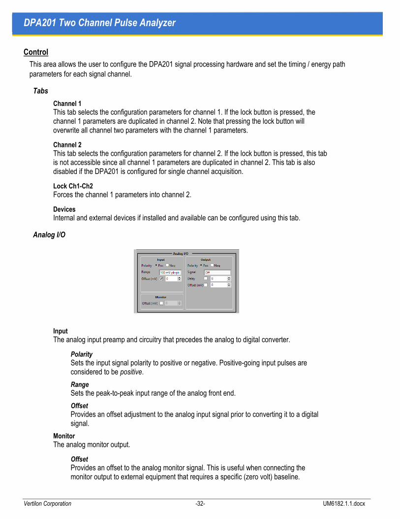
Analog I/O
Input The analog input preamp and circuitry that precedes the analog to digital converter.
Polarity Sets the input signal polarity to positive or negative. Positive-going input pulses are considered to be positive.
Range Sets the peak-to-peak input range of the analog front end.
Offset Provides an offset adjustment to the analog input signal prior to converting it to a digital signal.
Monitor The analog monitor output.
Offset Provides an offset to the analog monitor signal. This is useful when connecting the monitor output to external equipment that requires a specific (zero volt) baseline.
User Manual Graphical User Interface
Vertilon Corporation -33- UM6182.1.1.docx
Output The analog output circuitry that follows the waveform digital to analog converter.
Polarity Sets the output signal polarity to positive or negative. Positive polarity means that the analog output signal is not inverted with respect to the signal on the analog input port.
Signal Specifies which of the internal digital waveforms is converted to analog and routed to the analog output port. The choices are input, timing pre-filter, timing filter, trapezoidal filter, and pole-zero compensator.
Delay Provides a programmable delay that is added to the user-specified signal on the analog output port. This feature is valuable when external equipment connected to the analog output needs to be precisely timed relative to the signal on the analog input port.
Offset Provides an offset to the analog output signal. This is useful when connecting the analog output to external equipment that requires a specific (zero volt) baseline.
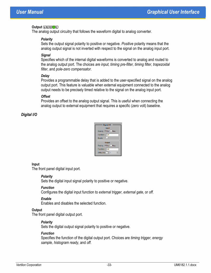
Digital I/O
Input The front panel digital input port.
Polarity Sets the digital input signal polarity to positive or negative.
Function Configures the digital input function to external trigger, external gate, or off.
Enable Enables and disables the selected function.
Output The front panel digital output port.
Polarity Sets the digital output signal polarity to positive or negative.
Function Specifies the function of the digital output port. Choices are timing trigger, energy sample, histogram ready, and off.

DPA201 Two Channel Pulse Analyzer
Vertilon Corporation -34- UM6182.1.1.docx
Delay Provides a programmable delay that is added to the user-specified signal on the digital output port.
Timing
Pre-Filter Timing parameters for the filter that precedes the discriminator.
Time Constant The pre-filter time constant that can be optionally enabled or disabled.
Arming Trigger arming circuit that pre-qualifies the discriminator.
Enable Enables and disables the discriminator pre-qualifying arming circuit.
Threshold Sets the arming threshold as a percentage of full scale in the signal chain. For leading edge trigger this threshold is the trigger threshold.
Armed Time The time in which the discriminator is armed after the input signal first crosses the arming threshold.
Discriminator The trigger generator for the timing chain.
Type Selects the type of discriminator used to trigger the data acquisition. The choices are external, internal, leading edge, crossover, and constant fraction.
Sample Delay Specifies the number of time samples of delay from the trigger to start the energy processing chain.
User Manual Graphical User Interface
Vertilon Corporation -35- UM6182.1.1.docx
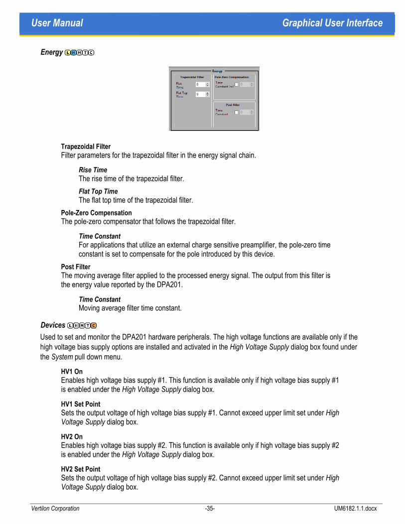
Energy
Trapezoidal Filter Filter parameters for the trapezoidal filter in the energy signal chain.
Rise Time The rise time of the trapezoidal filter.
Flat Top Time The flat top time of the trapezoidal filter.
Pole-Zero Compensation The pole-zero compensator that follows the trapezoidal filter.
Time Constant For applications that utilize an external charge sensitive preamplifier, the pole-zero time constant is set to compensate for the pole introduced by this device.
Post Filter The moving average filter applied to the processed energy signal. The output from this filter is the energy value reported by the DPA201.
Time Constant Moving average filter time constant.
Devices
Used to set and monitor the DPA201 hardware peripherals. The high voltage functions are available only if the high voltage bias supply options are installed and activated in the High Voltage Supply dialog box found under the System pull down menu.
HV1 On Enables high voltage bias supply #1. This function is available only if high voltage bias supply #1 is enabled under the High Voltage Supply dialog box.
HV1 Set Point Sets the output voltage of high voltage bias supply #1. Cannot exceed upper limit set under High Voltage Supply dialog box.
HV2 On Enables high voltage bias supply #2. This function is available only if high voltage bias supply #2 is enabled under the High Voltage Supply dialog box.
HV2 Set Point Sets the output voltage of high voltage bias supply #2. Cannot exceed upper limit set under High Voltage Supply dialog box.

DPA201 Two Channel Pulse Analyzer
Vertilon Corporation -36- UM6182.1.1.docx
Acquisition
The sampling parameters and acquisition mode for the DPA201 are configured in this section.
Modes
Oscillogram
Number of Waveforms Choose from 1 to 4 oscillogram waveforms to be collected.
Samples per Waveform Sets the number of samples logged for each waveform. All waveforms have the same number of samples. This number must be less than the number of samples per pulse specified above.
Waveform Source Selects the source for each of the collected waveforms. Choices are input signal, timing filter, trapezoidal filter, and pole-zero filter. The source can be taken from either of the two signal processing channels.
Trigger Offset The collected waveform can be shifted in time relative to the trigger signal. This parameter specifies the direction and amount of the shift.
List
List Data Up to four lists can be generated consisting of various combinations of pulse height, time of arrival, and time difference (as in coincidence measurements) from channels 1 and 2. Additionally, time of arrival and time difference data can be generated relative to the general purpose digital inputs from the DPA201 front panel.
Events per Payload Specifies the number of events to be accumulated before the list data is transmitted as a payload. All lists in a record have the same number of events. and are transmitted together once any one list is full. Partial lists that are transmitted under this condition are padded with zeroes. The number of events per payload should be small when the average event rate is low so that the statistics data can be updated more frequently. Making this number large when the average event rate is high improves data throughput.
Time Forces the transmission of the list data at the specified time interval. If a list becomes full before the specified time is reached, it is transmitted and the time interval is reset.
User Manual Graphical User Interface
Vertilon Corporation -37- UM6182.1.1.docx
Histogram
Histogram Data Various combinations of channels 1 and 2 pulse height, time of arrival, and time difference can be used to build the histogram. Time of arrival and time difference histograms can also be built using the general purpose digital inputs from the DPA201 front panel. A maximum of two histograms can be logged and displayed at any one time.
Histogram Stop Specifies the condition that stops the histogramming process so that the data can be transmitted to the user interface. Choices are elapsed time, number of events, bin threshold, and external gating. Histogramming stops if any of the checked conditions is met. The histogramming immediately resets and resumes once the data has been sent.
Histogram Bins Number of bins in the histogram. Both histograms have the same number of bins. The first bin out is zero height or zero time.
MCS
MCS Data A maximum of two MCS histograms can be logged and displayed at any one time. Time of arrival and time difference data is collected from channels 1 and 2, and the two external digital inputs.
MCS Stop Specifies the condition that stops the MCS histogramming process so that the data can be transmitted to the user interface. Choices are elapsed time, number of events, bin threshold, and external gating. MCS histogramming stops if any of the checked conditions is met. MCS histogramming immediately resets and resumes once the data has been sent.
MCS Bins The number of bins in the MCS histogram. Both MCS histograms have the same number of bins. The first bin out is zero time.
Parameters
Pulse Length The expected duration of the input pulse to the DPA201. For optimum performance and high accuracy, this value should be set to encompass 90 to 99% of the input signal.
Sampling Interval The sampling interval of the DPA201 can be changed from a minimum of 2 nsec to longer times in factor-of-two steps. Since the ADC always operates at the minimum sampling interval, longer times are attained through the use of a decimator. For short input pulse durations of about 1 usec or less, the best performance is achieved with this value set to the minimum. When longer pulse lengths are expected, this value should be increased so that the input pulse can be sampled entirely.
Samples per Pulse This value is computed by the system and is based on the user-defined parameters above. Accuracy of the calculated energy data is improved when more samples per pulses are taken however data throughput can be compromised in high event rate applications.

DPA201 Two Channel Pulse Analyzer
Vertilon Corporation -38- UM6182.1.1.docx
Dynamic Range The DPA201 internal signal processor maintains 20 bits of dynamic range but the dynamic range of the output data is limited to 16 bits. This parameter selects which part of the signal range is logged.
Time Scale Specifies the time resolution for all timing measurements. Reported time measurements are relative to this value and limited to 16 bits of dynamic range.
Channels Select single channel or dual channel acquisition. If single channel is selected, only channel 1 is enabled — channel two is disabled and therefore not used.
Run/Stop
Start and stop of the acquisition process is controlled in this section.
Run/Stop Controls
Acquisition Button
Run/Stop Starts the acquisition process. Once started, the control, acquisition, and playback areas become disabled if the log data box is checked. However, if the log data button is unchecked, the control area remains active so that the effects of changes to the timing and energy parameters can be observed in real time on the display. Pressing the button again stops the acquisition and returns full control of the interface to the user.
Log Data
Enable Specifies if a log file is created when the acquisition process is started. The log file can be played back using the playback area or can be read by an external software application.
Filename The name of the log file.
Stop Condition
Button Runs indefinitely until the run/stop button is pressed again.
Events Stops the acquisition after the specified number of events has occurred.
Running Time The acquisition runs for the amount of time specified and the stops.
Histograms Stops the acquisition after the specified number of histograms has occurred.
User Manual Graphical User Interface
Vertilon Corporation -39- UM6182.1.1.docx
Stop Parameters
Quantity The number associated with the stop condition.
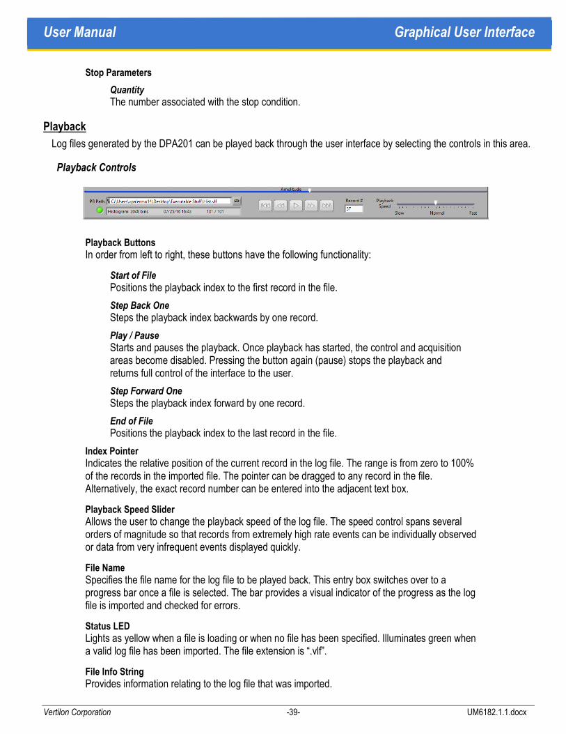
Playback
Log files generated by the DPA201 can be played back through the user interface by selecting the controls in this area.
Playback Controls
Playback Buttons In order from left to right, these buttons have the following functionality:
Start of File Positions the playback index to the first record in the file.
Step Back One Steps the playback index backwards by one record.
Play / Pause Starts and pauses the playback. Once playback has started, the control and acquisition areas become disabled. Pressing the button again (pause) stops the playback and returns full control of the interface to the user.
Step Forward One Steps the playback index forward by one record.
End of File Positions the playback index to the last record in the file.
Index Pointer Indicates the relative position of the current record in the log file. The range is from zero to 100% of the records in the imported file. The pointer can be dragged to any record in the file. Alternatively, the exact record number can be entered into the adjacent text box.
Playback Speed Slider Allows the user to change the playback speed of the log file. The speed control spans several orders of magnitude so that records from extremely high rate events can be individually observed or data from very infrequent events displayed quickly.
File Name Specifies the file name for the log file to be played back. This entry box switches over to a progress bar once a file is selected. The bar provides a visual indicator of the progress as the log file is imported and checked for errors.
Status LED Lights as yellow when a file is loading or when no file has been specified. Illuminates green when a valid log file has been imported. The file extension is “.vlf”.
File Info String Provides information relating to the log file that was imported.

DPA201 Two Channel Pulse Analyzer
Vertilon Corporation -40- UM6182.1.1.docx
Data Type Indicates the data type (e.g oscillogram, list, histogram, MCS) stored in the log file.
Payload Size Specifies the size of the payload in samples, events, or bins.
Creation Date Indicates the date and time when the log file was created.
Import Size / Original Size Shows the number of error-free records in the log file versus the total number of records. Errors can sometimes occur when the logging process is too fast for the host computer. This can be due to other computationally-intensive applications running on the computer. It is also possible that user-defined acquisition parameters are causing the DPA201 to generate excessive amounts of data.

User Manual Graphical User Interface
Vertilon Corporation -41- UM6182.1.1.docx
Display
The display area is used to provide a real-time graphical view of the data collected from any of the DPA201 acquisition modes. In playback mode, this area is used to view data from a previously logged log file.
Oscillogram View
Up to four internal waveforms from the DPA201 can be displayed here. This mode is very useful for diagnostics and initially setting up triggering positions, timing parameters, and filter time constants.
Channel Display Buttons Selects the channels for display.
Cursors Adjusts cursors.
Zoom / Pan Zooming and panning functionality

DPA201 Two Channel Pulse Analyzer
Vertilon Corporation -42- UM6182.1.1.docx
List Mode View
List data is displayed here as both a simple text list as well as a graphical view. Up to four lists can be shown simultaneously. The list view is useful when it is necessary to determine the exact values associated with a specific event. Graphical view is very helpful when locating a specific region (e.g. point in time) of event activity.
Event Number Indicates the event number that corresponds to the cursor position in the current record. The maximum value for this parameter is equal to the number of events per payload as specified in the list mode section.
Scroll Bar Used to scroll through the list data in the selected record.
Cursor As an alternative to scrolling through the list data, the cursor in the graphical view can be moved to any location in the current record.
User Manual Graphical User Interface
Vertilon Corporation -43- UM6182.1.1.docx
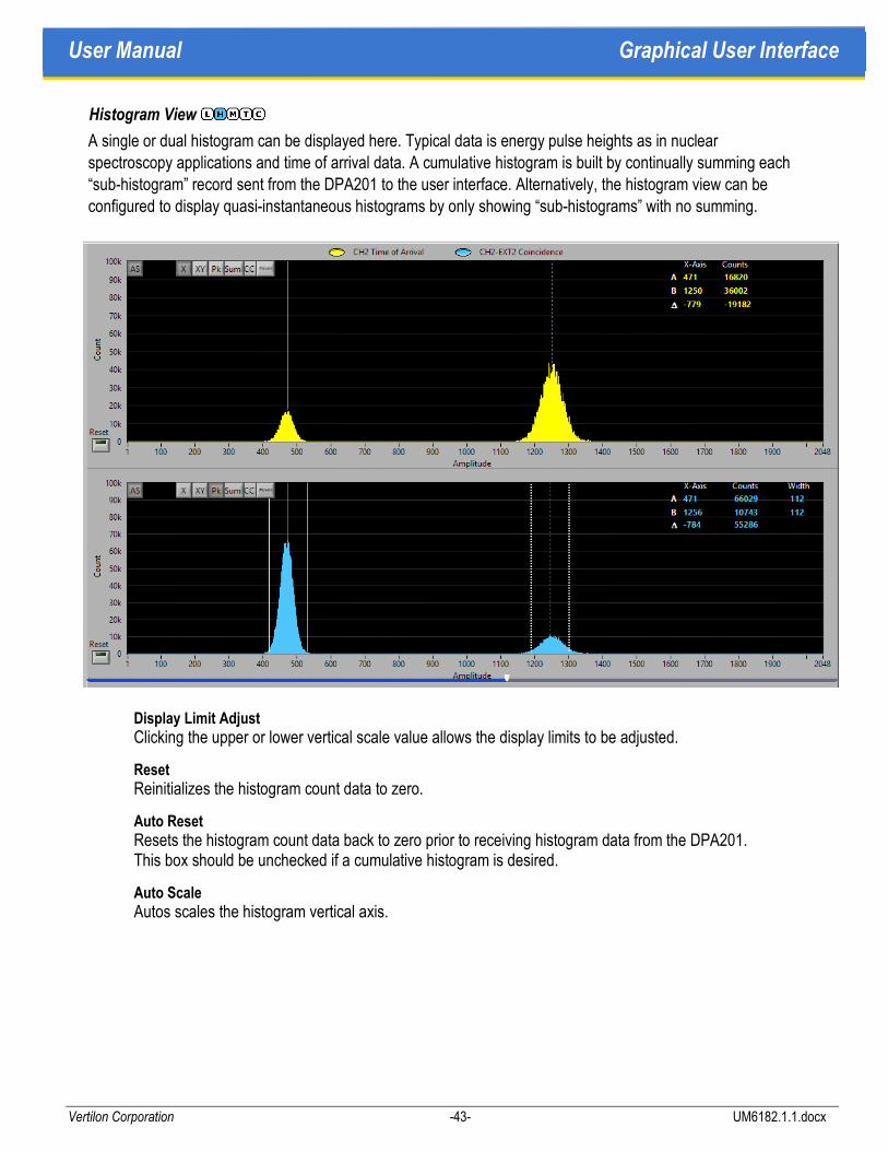
Histogram View
A single or dual histogram can be displayed here. Typical data is energy pulse heights as in nuclear spectroscopy applications and time of arrival data. A cumulative histogram is built by continually summing each “sub-histogram” record sent from the DPA201 to the user interface. Alternatively, the histogram view can be configured to display quasi-instantaneous histograms by only showing “sub-histograms” with no summing.
Display Limit Adjust Clicking the upper or lower vertical scale value allows the display limits to be adjusted.
Reset Reinitializes the histogram count data to zero.
Auto Reset Resets the histogram count data back to zero prior to receiving histogram data from the DPA201. This box should be unchecked if a cumulative histogram is desired.
Auto Scale Autos scales the histogram vertical axis.

DPA201 Two Channel Pulse Analyzer
Vertilon Corporation -44- UM6182.1.1.docx
MCS View
MCS histograms showing time of arrival data versus a trigger are displayed in this view. Single and dual histogram views are possible. A cumulative MCS histogram is built by continually summing each “sub-histogram” record sent from the DPA201 to the user interface. Alternatively, the MCS histogram view can be configured to display quasi-instantaneous histograms by only showing “sub-histograms” with no summing.
Display Limit Adjust Clicking the upper or lower vertical scale value allows the display limits to be adjusted.
Reset Reinitializes the MCS histogram count data to zero.
Auto Reset Resets the MCS histogram count data back to zero prior to receiving histogram data from the DPA201. This box should be unchecked if a cumulative histogram is desired.
Auto Scale Autos scales the MCS histogram vertical axis.
Statistics
Real time statistics derived from the data transmitted from the DPA201 are shown here.
Reporting Tab
Record Data Data relating to the specific record that is currently being displayed.
Record Number The current record number. Records containing errors are deleted from playback.
Running Time The total running time in seconds from the start of the acquisition.
Difference Time The difference in time from the current record and the previous record. This number typically represents the amount of time required to collect one record of data. The time is invalid if a record is missing.
Channel 1 Real time statistics from the A and B counters from channel 1.
Total (A) Running total of A counts on channel 1.
User Manual Graphical User Interface
Vertilon Corporation -45- UM6182.1.1.docx
Average Rate (A) Average rate of A counts on channel 1 calculated by dividing the total (A) by the running time.
Gated Rate (A) Instantaneous rate of A counts on channel 1 calculated by taking the number A counts that occurred during the gate time and dividing the result by the gate time.
Total (B) Running total of B counts on channel 1.
Average Rate (B) Average rate of B counts on channel 1 calculated by dividing the total (B) by the running time.
Gated Rate (B) Instantaneous rate of B counts on channel 1 calculated by taking the number B counts that occurred during the gate time and dividing the result by the gate time. Gated rate is disabled during playback mode.
Channel 2 Real time statistics from the A and B counters from channel 2.
Total (A) Running total of A counts on channel 2.
Average Rate (A) Average rate of A counts on channel 2 calculated by dividing the total (A) by the running time.
Gated Rate (A) Instantaneous rate of A counts on channel 2 calculated by taking the number A counts that occurred during the gate time and dividing the result by the gate time.
Total (B) Running total of B counts on channel 2.
Average Rate (B) Average rate of B counts on channel 2 calculated by dividing the total (B) by the running time.
Gated Rate (B) Instantaneous rate of B counts on channel 2 calculated by taking the number B counts that occurred during the gate time and dividing the result by the gate time. Gated rate is disabled during playback mode.

DPA201 Two Channel Pulse Analyzer
Vertilon Corporation -46- UM6182.1.1.docx
Setup Tab
Counters User-specified parameters for setting up the system counters and count rate calculations.
Channel 1 Gate Time Specifies the gate time for the channel 1 gated rate calculation.
Channel 2 Gate Time Specifies the gate time for the channel 2 gated rate calculation.
Channel 1 A Counter Definition Parameters for A counter setup. Include A counter label
Channel 1 B Counter Definition Parameters for B counter setup.
Channel 2 A Counter Definition Parameters for A counter setup. Include A counter label
Channel 2 B Counter Definition Parameters for B counter setup.
Coincidence Needs definitions.
Error Reporting Specifies error reporting conditions
Record OOR Indicates that data in the record is out of range.
Real-Time OOR Live out-of range reporting for any waveform in the processing channel.
Front Panel Display Indicates what statistics are reported on the DPA201 front panel.
Ch 1 / Ch 2 Counts / Rates Default display.
Ch 1 Only Counts, rates, record number and time data.
Ch 2 Only Counts, rates, record number and time data.

User Manual Graphical User Interface
Vertilon Corporation -47- UM6182.1.1.docx
Pull Down Menus
The pull down menus are available at the top of the graphical user interface window.
File
File operations generally consist of storing and retrieving DPA201 configurations on the PC. The last known configuration will be loaded when power to the unit is applied. If the last configuration cannot be found, the default configuration is loaded.
New Loads the DPA201 with the default configuration.
Open Loads the DPA201 with a stored configuration from a file on the PC.
Save Saves the current configuration of the DPA201 to a file on the PC.
Save As Saves the current configuration of the DPA201 to a new file on the PC.
Print Window Prints the current window.
Exit Closes the executable.

DPA201 Two Channel Pulse Analyzer
Vertilon Corporation -48- UM6182.1.1.docx
System
Other configuration settings for the DPA201 are accessed through this menu.
Data Configuration Opens the dialog box shown to configure the data configuration.
High Voltage Supplies Opens the dialog box shown below where the optional high voltage bias supplies are configured.
Enable HV1 Allows optional high voltage bias supply #1 to be controlled from the device tab on the front panel. If this box is unchecked, the supply is turned off and the front panel controls are disabled.
Enable HV2 Allows optional high voltage bias supply #2 to be controlled from the device tab on the front panel. If this box is unchecked, the supply is turned off and the front panel controls are disabled.
HV1 Limit Sets the voltage limit for high voltage bias supply #1 so that the user cannot select a set point above this level from the front panel.
HV2 Limit Sets the voltage limit for high voltage bias supply #2 so that the user cannot select a set point above this level from the front panel.

User Manual Graphical User Interface
Vertilon Corporation -49- UM6182.1.1.docx
Utilities
Add Option This utility allows the user to add certain software features to the DPA201 in the field. An option code obtained from Vertilon is inserted in the dialog box to upgrade the unit.


User Manual Log Files
Vertilon Corporation -51- UM6182.1.1.docx
Log Files
The Control and Acquisition Interface Software produces binary log files during data collection that can be viewed using the GUI display or processed off-line for more thorough data analysis. The GUI display function is accessed using the playback controls on the front panel. This mode allows the user to step through and view individual records in the binary log file. More advanced data processing functions such as histogramming, noise rejection, sorting, and pattern detection can be applied by operating directly on the binary log files.
Figure 10: Log File Format
Log File Format
Binary log files are used to minimize the time required to transfer the data from the DPA201 to the disk on the PC and to reduce processing overhead and storage requirements. The contents of the binary log files written by the Control and Acquisition Interface Software are partitioned into three sections; the identification text header (ID Text Header), the configuration table (Config Table), and the data section (Data). The format is illustrated in the figure on the previous page.
33
PS·33
Descriptor
Payload #K
33
PS·33
33Descriptor
Custom Configuration Table
User Configuration Table
Configuration Table Revision
ID Text Header Data
Factory Configuration Table
32
1
750
1000
250
Payload #1
Contents WordsSize
32
2001
K·(PS+1)·33
PS·33
LOG FILE
HEADER
CONFIG TABLE
DATA
Section
Descriptor
Payload #2

DPA201 Two Channel Pulse Analyzer
Vertilon Corporation -52- UM6182.1.1.docx
Identification Text Header
The ID Text Header defined in Table 1 below is a simple header that identifies the DPA201 model number, date, time (24 hour format), and version information. It is organized along 8-bit byte boundaries.
Offset (Bytes) Description Length (Bytes) Contents
0 Product ID 17 "Vertilon xxxxxx[CR][LF]"
17 Date/Time String 19 "MM/DD/YY HH:MM xx[CR][LF]"
36 Software UI Version 28 "LabVIEW UI Version xxxxxxx[CR][LF]"
Table 1: Log File (ID Text Header Section)
Configuration Table
The Config Table section shown in Table 2 contains configuration information relating to the DPA201 hardware and firmware. Unlike the Header section which is organized as 8-bit bytes, the Config Table section is instead organized as 16-bit words. The configuration data is partitioned into three tables; user, custom, and factory. The user table contains the configuration of the DPA201 set by the user through the user interface. Any custom configuration data is stored in the custom table. Factory-programmed, read-only configuration data is found in the factory table.
Offset (Words) Description Length (Words) Contents
32 Config Table Revision 1 1st 8 bits = Major Rev,
33 User Config Table 1000 User Configuration Binary Data
1033 Custom Config Table 250 Custom Configuration Binary Data
1283 Factory Config Table 750 Factory Configuration Binary Data
Table 2: Log File (Config Table Section)
Data Section
The data acquired during logging is found in the Data Section which is a series of packets comprised of a one word header followed by 32 words of data. These packets are organized into higher level structures of either a descriptor or a payload. A descriptor carries system information relating to count rates, event totals, timestamps, and status whereas a payload contains the bulk data generated during the acquisition process. The descriptorsize is always one packet in length. The payload size (PS) is many packets in length and is dependent on the system acquisition mode and configuration parameters. In general, the Data Section is a repeating sequence of a one packet descriptor followed by PS packets of payload with one exception — the exception being that to keep the real-time statistics up-to-date when the event rate is very low or intermittent, a descriptor is occasionally sent with no payload following it. This special case can be thought of as part of the normal sequence except with a payload size of zero. The Data Section in Figure 10 illustrates a typical case of K payloads of PS length with no zero length payloads. A more detailed description of the descriptor / payloadformat and sequence is provided below and illustrated in Figure 11.

User Manual Log Files
Vertilon Corporation -53- UM6182.1.1.docx
Figure 11: Descriptor / Payload Sequence
H0
DISCRIPTOR WORDSHDR
D2 D3 D4 D5 D6 D7 D8 D9 D10 D11 D12 D13 D14 D15 D16D0 D1 D17 D18 D19 D20 D21 D22 D23 D24 D25 D26 D27 D28 D29
DescriptorPacket
H0
PAYLOADHDR
P0 P1 P2 P3 P4 P5 P6 P7 P8 P9 P10 P11 P12 P13 P14 P15 P16 P30 P31P17 P18 P19 P20 P21 P22 P23 P24 P25 P26 P27 P28 P29
PayloadPacket
0
H0
PAYLOADHDR
P0 P1 P2 P3 P4 P5 P6 P7 P8 P9 P10 P11 P12 P13 P14 P15 P16 P30 P31P17 P18 P19 P20 P21 P22 P23 P24 P25 P26 P27 P28 P29
H0
PAYLOADHDR
P0 P1 P2 P3 P4 P5 P6 P7 P8 P9 P10 P11 P12 P13 P14 P15 P16 P30 P31P17 P18 P19 P20 P21 P22 P23 P24 P25 P26 P27 P28 P29
PayloadPacket
1
PayloadPacketPS-1
PL UNUSED
‘0’(1b)
TYPE(3b) (11b)
PF
‘0’(1b)
Payload Type(TYPE)
0: Oscillogram1: List2: Histogram3: MCS4: Reserved5: Info 16: Info 27: Info 3
PL = ‘0’Discriptor
Packet
PF = ‘0’No Payload
Follows
TYPE
Descriptor Packet (No Payload Follows)
PL PAYLOAD SIZE
‘0’(1b)
TYPE(3b)
PS-1(11b)
PF
‘1’(1b)
TYPE
PL PACKET NUMBER
‘1’(1b)
PKV(3b)
PN(11b)
PF
‘1’(1b)
PACKET VALID
PL PACKET NUMBER
‘1’(1b)
PKV(3b)
PN(11b)
PF
‘0’(1b)
PACKET VALID
Descriptor Packet (Payload Follows)
Any Payload Packet Except Last One
Last Payload Packet
PL = ‘0’Discriptor
Packet
PF = ‘1’PayloadFollows
PL = ‘1’PayloadPacket
PF = ‘1’PayloadFollows
PL = ‘1’PayloadPacket
PF = ‘0’No Payload
Follows
Payload Size(PS-1)
0 to 2047
Packet Number(PN)
0 to PS-2
Packet Number(PN) PS-1
H0
PAYLOADHDR
P0 P1 P2 P3 P4 P5 P6 P7 P8 P9 P10 P11 P12 P13 P14 P15 P16 P30 P31P17 P18 P19 P20 P21 P22 P23 P24 P25 P26 P27 P28 P29
PayloadPacketPS-2
...
D30 D31
Packet Valid(PKV)
0: Not Valid1:2:3:4: P0 to P75: P0 to P156: P0 to P237: P0 to P31
Packet Valid(PKV)
0: Not Valid1:2:3:4: P0 to P75: P0 to P156: P0 to P237: P0 to P31

DPA201 Two Channel Pulse Analyzer
Vertilon Corporation -54- UM6182.1.1.docx
Descriptor Packet (Header) The PL field in the 16 bit header word is used to designate if a packet is a descriptor packet (PL=0) or payload packet (PL=1). If the packet is a descriptor packet, then the PF field is used to specify if a payload follows it (PF=1). When a payload follows, the TYPE field indicates the type of data (e.g. oscillogram, list, histogram, etc.) in the payload and the PS field specifies its size. Together the TYPE and PS fields indicate what is in the payload (e.g. samples, events, or bins) and how many of them (PS x 32). When no payload follows the descriptor packet (PF=0), the PS field is unused.
Descriptor Packet (Descriptor Words) The 32 descriptor words, whose format is shown below, convey information relating to payload number, time, and status conditions as well as event count totals and triggering statistics. System configuration parameters (SYSCFG) are included as part of the descriptor words. As shown in Table 4, they contain information relating to the details of the data acquisition setup. An additional field called the payload details (PLDDET) provides information identifying the data in the current payload along with associated offset and scaling factors.
DESCRIPTOR WORDS (32)
RECORDNUM (2)
RUNNINGTIME
(2)
DIFF TIME
(2)
CH1 TOT A
(3)
CH2 TOT A
(3)
CH1 TOT B
(3)
CH2 TOT B
(3) ERR (2)
RESERVED (7)
SYSCFG (3)
PLDDET(2)
FIELD WORDS DESCRIPTION RANGE VALUE
RECORD NUM 2
Running count of the records in the log file. Depending on the system configuration, there can be
up to four payloads associated with each record number. The payload within each record is
specified in PLDDET. The record number is zero when a descriptor packet with no payload is sent.
0 to 232-1 0 to 4.295 x 10⁹
RUNNING TIME 2 Running time from start of acquisition. Units are 1 msec. 0 to 232-1 0 to 1,193 hrs
DIFFERENCE TIME 2 Time difference between the current record and the last record. For the first record out, this
number is referenced to t=0. Units are 2 nsec times the decimation factor (DF). 0 to 232-1
8.59 sec max
up to
137.4 sec max
CH1 TOT A 3 Running total of Channel 1 events that meet first trigger condition. 0 to 248-1 0 to 2.81 x 10¹⁴
CH2 TOT A 3 Running total of Channel 2 events that meet first trigger condition. 0 to 248-1 0 to 2.81 x 10¹⁴
CH1 TOT B 3 Running total of Channel 1 events that meet all trigger conditions. 0 to 248-1 0 to 2.81 x 10¹⁴
CH2 TOT B 3 Running total of Channel 2 events that meet all trigger conditions. 0 to 248-1 0 to 2.81 x 10¹⁴
ERR 2 Error codes indicating over and under range and pile-up conditions.
RESERVED 7 Reserved for reporting of application specific conditions such as other events, max heights, etc.
SYSCFG 3 System configuration parameters for log file. Unchanged for all payloads.
PLDDET 2 Payload details for the current payload.
Table 3: Descriptor Words
Payload Packet (Header) The PL field in the header word is 1 when a payload packet is sent. If this packet is any payloadpacket other than the last payload packet, then PF is also 1 indicating that another payloadpacket follows. For the very last payload packet, PF is 0 indicating that no more payload packets follow. The PN field in the header is used to specify the payload packet number currently being sent. Valid words in the payload packet are identified by the PKV field. This field is typically used to signify when a payload packet is empty or only partially filled with valid data.
Payload Packet (Payload Data) Each payload packet contains 32 words of payload data. Payload data is sequentially strung together to form the payload. Typical payloads are oscillogram, list mode, histogram, and MCS data. All payload words are encoded as 16-bit unsigned integers with the exceptions of the oscillogram waveform data and the time difference data from list mode. These are encoded as
User Manual Log Files
Vertilon Corporation -55- UM6182.1.1.docx
16-bit two’s complement integers. Unsigned integers have a minimum value of 0x0000 and a maximum value of 0xFFFF which represents an overflow. For two’s complement integers, the maximum positive (0x7FFF) and negative (0x8000) values are considered as overflow and underflow conditions, respectively.

DPA201 Two Channel Pulse Analyzer
Vertilon Corporation -56- UM6182.1.1.docx
SYSCFG
(3 words / 48 bits)
DSRC (4b)
SRC0 (4b)
SRC1 (4b)
SRC2 (4b)
SRC3 (4b)
SI (3b)
HS (3b)
TS (5b)
CH(1b)
HS (3b)
HS (3b)
RSVD (10b)
FIELD BITS DESCRIPTION # OSCILLOGRAM
VALUES
LIST
VALUES
HISTOGRAM
VALUES
MCS
VALUES
DSRC 4 Source and type of data in the payload
sequence (the record). Up to four
consecutive payloads are supported.
Index value in PLDDET field indicates
current payload’s data.
0
1
2
3
4
5
6
7
W1
W1, W2
W1, W2, W3
W1, W2, W3, W4
H1
T1
H1, H2
T1, T2
H1, T1
H1, H2, ∆T
H1, T1, H2, T2
∆T
H1
T1
H1, H2
T1, T2
∆T
T1
T1, T2
∆T
SRC0 4 Index 0 data source. 0
1
2
3
8
9
10
11
12
13
14
15
CH1 Input
CH1 Timing Filter
CH1 Trapezoid Filter
CH1 Pole-Zero Filter
CH2 Input
CH2 Timing Filter
CH2 Trapezoid Filter
CH2 Pole-Zero Filter
CH1
EXT1
CH1(H)
CH2(H)
CH2
EXT2
CH1-CH2
CH1-EXT1
CH1-EXT2
CH2-EXT1
CH2-EXT2
EXT1-EXT2
CH1
EXT1
CH1(H)
CH2(H)
CH2
EXT2
CH1-CH2
CH1-EXT1
CH1-EXT2
CH2-EXT1
CH2-EXT2
EXT1-EXT2
CH1
EXT1
CH2
EXT2
CH1-CH2
CH1-EXT1
CH1-EXT2
CH2-EXT1
CH2-EXT2
EXT1-EXT2
SRC1 4 Index 1 data source. Same as above
SRC2 4 Index 2 data source. Same as above
SRC3 4 Index 3 data source. Same as above
SI 3 Sampling interval. Used to configure the
decimator. Also called the decimation
factor.
0
1
2
3
4
1
2
4
8
16
HS 3 Height scale 0
1
2
3
4
1
2
4
8
16
TS 5 Time scale 0
1
2
8
9
10
18
19
Ts / 256
Ts / 128
Ts / 64
Ts
Ts x 2
Ts x 4
Ts x 1024
Ts x 2048
CH 1 Number of enabled channels. 0
1
1
2
CHG1 3 Channel 1 gain. 0
1
5
1/8
1/4
4
CHG2 3 Channel 2 gain. 0
1
5
1/8
1/4
4
RSVD 10 Reserved
Table 4: SYSCFG Format

User Manual Log Files
Vertilon Corporation -57- UM6182.1.1.docx
OSCILLOGRAM PLDDET
(2 words / 32 bits)
WIDX (3b)
WP(1b)
WOFFSET (12b)
RESERVED (16b)
FIELD BITS PARAMETER DESCRIPTION # VALUE
WIDX 3 Waveform Index The waveform number in the payload. 0
1
2
3
0
1
2
3
WP 1 Waveform Offset Polarity The waveform offset direction from the trigger position. 0
1
Negative Time
Positive Time
WOFFSET 12 Waveform Offset The number of samples the waveform is offset from the trigger position. 0
1
4095
0 samples
1 samples
4095 samples
RESERVED 16 Reserved
Table 5: Oscillogram PLDDET
Figure 12: Oscillogram Payload Packets
Event Window(N Samples)
S0 S1 S2 SN-2 SN-1Samples S3 to SN-3
PAYLOAD
P0 P1 P2 P3 P4 P5 P6 P7 P8 P9 P10 P11 P12 P13 P14 P15 P16 P30 P31P17 P18 P19 P20 P21 P22 P23 P24 P25 P26 P27 P28 P29
S0 S1 S2 S3 S4 S5 S6 S7 S8 S9 S10 S11 S12 S13 S14 S15 S16 S30 S31S17 S18 S19 S20 S21 S22 S23 S24 S25 S26 S27 S28 S29Packet 0
...
S40 S41 S42 S43 S44 S45 S46 S60S47 S48 S49 S50 S51 S52 S53 S54 S55 S56 S57 S58 S59 S61 S62 S63
S64 S65 S66 S67 S68 S69
S32 S33 S34 S35 S36 S37 S38 S39
S71 S72 S73 S74 S75 S76 S77 S78 S79S70 S81 S82 S83 S84 S85 S86 S87 S88 S89S80
Packet 1
Packet 2 S91 S92 S93 S94 S95S90
SN-10SN-11SN-12SN-13SN-14SN-15SN-16SN-30 SN-17SN-18SN-19SN-20SN-21SN-22SN-23SN-24SN-25SN-26SN-27SN-28SN-29SN-31SN-32 SN-2SN-3SN-4SN-5SN-6SN-7SN-8SN-9
SN-64 SN-40SN-41SN-42SN-43SN-44SN-45SN-46SN-60 SN-47SN-48SN-49SN-50SN-51SN-52SN-53SN-54SN-55SN-56SN-57SN-58SN-59SN-61SN-62SN-63 SN-33SN-34SN-35SN-36SN-37SN-38SN-39
SN-1Packet PS-1
Packet PS-2
Payload

DPA201 Two Channel Pulse Analyzer
Vertilon Corporation -58- UM6182.1.1.docx
LIST MODE PLDDET
(2 words / 32 bits)
LIDX (3b)
RESERVED (29b)
FIELD BITS PARAMETER DESCRIPTION # VALUE
LIDX 3 List Mode Index The data in the payload. Index to list mode type list (DSRC). 0
1
2
3
0
1
2
3
RESERVED 29 Reserved
Table 6: List Mode PLDDET
Figure 13: List Mode Payload Packets
PAYLOAD
P0 P1 P2 P3 P4 P5 P6 P7 P8 P9 P10 P11 P12 P13 P14 P15 P16 P30 P31P17 P18 P19 P20 P21 P22 P23 P24 P25 P26 P27 P28 P29
E0 E1 E2 E3 E4 E5 E6 E7 E8 E9 E10 E11 E12 E13 E14 E15 E16 E30 E31E17 E18 E19 E20 E21 E22 E23 E24 E25 E26 E27 E28 E29Packet 0
...
E40 E41 E42 E43 E44 E45 E46 E60E47 E48 E49 E50 E51 E52 E53 E54 E55 E56 E57 E58 E59 E61 E62 E63
E64 E65 E66 E67 E68 E69
E32 E33 E34 E35 E36 E37 E38 E39
E71 E72 E73 E74 E75 E76 E77 E78 E79E70 E81 E82 E83 E84 E85 E86 E87 E88 E89E80
Packet 1
Packet 2 E91 E92 E93 E94 E95E90
EN-10EN-11EN-12EN-13EN-14EN-15EN-16EN-30 EN-17EN-18EN-19EN-20EN-21EN-22EN-23EN-24EN-25EN-26EN-27EN-28EN-29EN-31EN-32 EN-2EN-3EN-4EN-5EN-6EN-7EN-8EN-9
EN-64 EN-40EN-41EN-42EN-43EN-44EN-45EN-46EN-60 EN-47EN-48EN-49EN-50EN-51EN-52EN-53EN-54EN-55EN-56EN-57EN-58EN-59EN-61EN-62EN-63 EN-33EN-34EN-35EN-36EN-37EN-38EN-39
EN-1Packet PS-1
Packet PS-2
Payload
E0 E1 E2 EN-2 EN-1
Event Samples(N Events)
HeightEvent
Sample
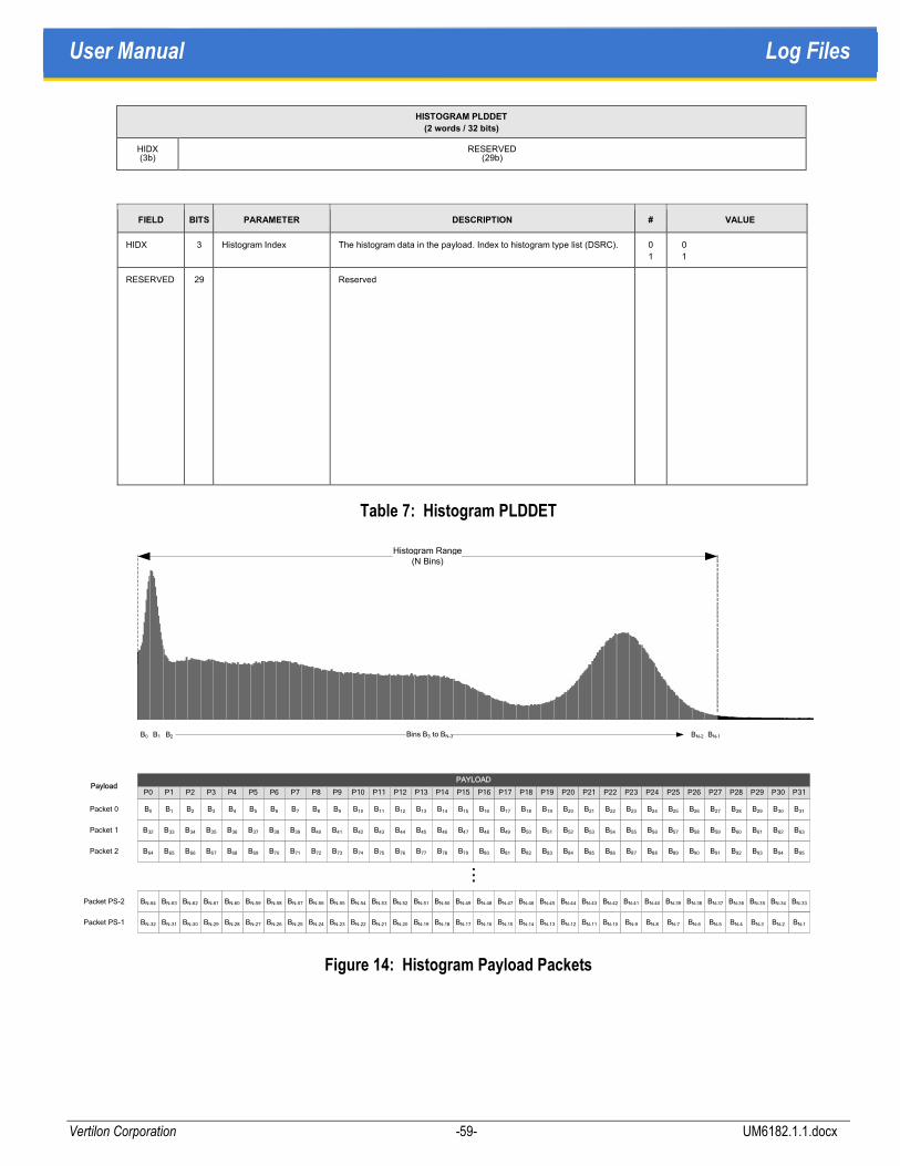
User Manual Log Files
Vertilon Corporation -59- UM6182.1.1.docx
HISTOGRAM PLDDET
(2 words / 32 bits)
HIDX (3b)
RESERVED (29b)
FIELD BITS PARAMETER DESCRIPTION # VALUE
HIDX 3 Histogram Index The histogram data in the payload. Index to histogram type list (DSRC). 0
1
0
1
RESERVED 29 Reserved
Table 7: Histogram PLDDET
Figure 14: Histogram Payload Packets
PAYLOAD
P0 P1 P2 P3 P4 P5 P6 P7 P8 P9 P10 P11 P12 P13 P14 P15 P16 P30 P31P17 P18 P19 P20 P21 P22 P23 P24 P25 P26 P27 P28 P29
B0 B1 B2 B3 B4 B5 B6 B7 B8 B9 B10 B11 B12 B13 B14 B15 B16 B30 B31B17 B18 B19 B20 B21 B22 B23 B24 B25 B26 B27 B28 B29Packet 0
...
B40 B41 B42 B43 B44 B45 B46 B60B47 B48 B49 B50 B51 B52 B53 B54 B55 B56 B57 B58 B59 B61 B62 B63
B64 B65 B66 B67 B68 B69
B32 B33 B34 B35 B36 B37 B38 B39
B71 B72 B73 B74 B75 B76 B77 B78 B79B70 B81 B82 B83 B84 B85 B86 B87 B88 B89B80
Packet 1
Packet 2 B91 B92 B93 B94 B95B90
BN-10BN-11BN-12BN-13BN-14BN-15BN-16BN-30 BN-17BN-18BN-19BN-20BN-21BN-22BN-23BN-24BN-25BN-26BN-27BN-28BN-29BN-31BN-32 BN-2BN-3BN-4BN-5BN-6BN-7BN-8BN-9
BN-64 BN-40BN-41BN-42BN-43BN-44BN-45BN-46BN-60 BN-47BN-48BN-49BN-50BN-51BN-52BN-53BN-54BN-55BN-56BN-57BN-58BN-59BN-61BN-62BN-63 BN-33BN-34BN-35BN-36BN-37BN-38BN-39
BN-1Packet PS-1
Packet PS-2
Payload
BN-2 BN-1Bins B3 to BN-3
Histogram Range(N Bins)
B0 B1 B2
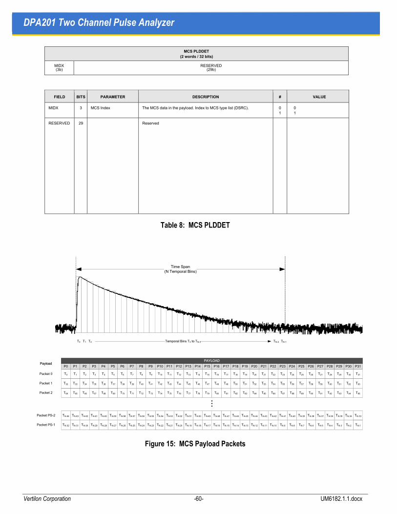
DPA201 Two Channel Pulse Analyzer
Vertilon Corporation -60- UM6182.1.1.docx
MCS PLDDET
(2 words / 32 bits)
MIDX (3b)
RESERVED (29b)
FIELD BITS PARAMETER DESCRIPTION # VALUE
MIDX 3 MCS Index The MCS data in the payload. Index to MCS type list (DSRC). 0
1
0
1
RESERVED 29 Reserved
Table 8: MCS PLDDET
Figure 15: MCS Payload Packets
PAYLOAD
P0 P1 P2 P3 P4 P5 P6 P7 P8 P9 P10 P11 P12 P13 P14 P15 P16 P30 P31P17 P18 P19 P20 P21 P22 P23 P24 P25 P26 P27 P28 P29
T0 T1 T2 T3 T4 T5 T6 T7 T8 T9 T10 T11 T12 T13 T14 T15 T16 T30 T31T17 T18 T19 T20 T21 T22 T23 T24 T25 T26 T27 T28 T29Packet 0
...
T40 T41 T42 T43 T44 T45 T46 T60T47 T48 T49 T50 T51 T52 T53 T54 T55 T56 T57 T58 T59 T61 T62 T63
T64 T65 T66 T67 T68 T69
T32 T33 T34 T35 T36 T37 T38 T39
T71 T72 T73 T74 T75 T76 T77 T78 T79T70 T81 T82 T83 T84 T85 T86 T87 T88 T89T80
Packet 1
Packet 2 T91 T92 T93 T94 T95T90
TN-10TN-11TN-12TN-13TN-14TN-15TN-16TN-30 TN-17TN-18TN-19TN-20TN-21TN-22TN-23TN-24TN-25TN-26TN-27TN-28TN-29TN-31TN-32 TN-2TN-3TN-4TN-5TN-6TN-7TN-8TN-9
TN-64 TN-40TN-41TN-42TN-43TN-44TN-45TN-46TN-60 TN-47TN-48TN-49TN-50TN-51TN-52TN-53TN-54TN-55TN-56TN-57TN-58TN-59TN-61TN-62TN-63 TN-33TN-34TN-35TN-36TN-37TN-38TN-39
TN-1Packet PS-1
Packet PS-2
Payload
T0 T1 T2 Temporal Bins T3 to TN-3
Time Span(N Temporal Bins)
TN-2 TN-1

User Manual Configuration Tables
Vertilon Corporation -61- UM6182.1.1.docx
Configuration Tables
The hardware and software configuration of the DPA201 is stored in three separate tables; user, custom, and factory configuration tables. The sections that follow summarize the contents of the three tables. Some configuration parameters are not used in the DPA201. Additionally, parameter limits may differ depending on the software options installed in the DPA201.
User Configuration Table
The user table contains the configuration of the DPA201 set by the user through the user interface. It is 1000 words long and is described in the table below.
Index Parameter Name Type Description Parameter Limits
0 SystemMode 16 SHORT Indicates current system mode, acquire or
standby mode
0 = Standby Mode
1 = Acquire Mode
1 HVLimit0 16 SHORT Maximum allowed voltage on HV supply 1 Range = 100 – 13900 (10 – 1390V)
2 HVLimit1 16 SHORT Maximum allowed voltage on HV supply 2 Range = 100 – 13900 (10 – 1390V)
3 NumChannelsB0 16 SHORT Number of channels enabled bank 1 Range = 0 – 64
4 NumChannelsB1 16 SHORT Number of channels enabled bank 2 Range = 0 – 64
5 NumChannelsB2 16 SHORT Number of channels enabled bank 3 Range = 0 – 64
6 NumChannelsB3 16 SHORT Number of channels enabled bank 4 Range = 0 – 64
7 HVEnabled 16 SHORT Enables for high voltage supplies Bit 0 = HV Supply 1 Enable/Disable
Bit 1 = HV Supply 2 Enable/Disable
8 HVSetpoint0 16 SHORT Current setpoint HV supply 1 (DAC 6) Range = 100 – 13900 (10 – 1390V)
9 HVSetpoint1 16 SHORT Current setpoint HV supply 2 (DAC 7) Range = 100 – 13900 (10 – 1390V)
10 UserConfigID 16 SHORT Unused N/A (0 – 65535)
11 DCRD_AOut_0 16 SHORT Daughtercard analog out control (DAC 8) 0-4095 (3.0V full scale)
12 BandEnables 16 SHORT Spectral filtering band enables Range = 0 – 255 (each bit position
corresponds to 1 of 8 band enables)
13 Band0StartIndex 16 SHORT Start index for spectral filtering band 1 Range = 0 – 255 (1 channel per bit)
14 Band0EndIndex 16 SHORT End index for spectral filtering band 1 Range = 0 – 255 (1 channel per bit)
15-28 Band Indices for
Remaining Bands
16 SHORT Start index for spectral filtering band 2 - 8
End index for spectral filtering band 2 - 8
Range = 0 – 255 (1 channel per bit)
29 FlagEnables 16 SHORT Spectral filtering flag enables Range = 0 – 255 (each bit position
corresponds to a flag enable)
30-33 Flag0Operand0-
Flag0Operand3
16 SHORT Spectral filtering operands for flag 1
configuration
Flag0Operand0,2
Range = 0 – 32767
Flag0Operand1,3
Range = 0 – 7 or 65535
(1 channel per bit or LSB wgt, 65535)
34-37 Flag1Operand0-
Flag1Operand3
16 SHORT Spectral filtering operands for flag 2
configuration
Same as Above
38-41 Flag2Operand0-
Flag2Operand3
16 SHORT Spectral filtering operands for flag 3
configuration
Same as Above

DPA201 Two Channel Pulse Analyzer
Vertilon Corporation -62- UM6182.1.1.docx
Index Parameter Name Type Description Parameter Limits
42-45 Flag3Operand0-
Flag3Operand3
16 SHORT Spectral filtering operands for flag 4
configuration
Same as Above
46-49 Flag4Operand0-
Flag4Operand3
16 SHORT Spectral filtering operands for flag 5
configuration
Same as Above
50-53 Flag5Operand0-
Flag5Operand3
16 SHORT Spectral filtering operands for flag 6
configuration
Same as Above
54-57 Flag6Operand0-
Flag6Operand3
16 SHORT Spectral filtering operands for flag 7
configuration
Same as Above
58-61 Flag7Operand0-
Flag7Operand3
16 SHORT Spectral filtering operands for flag 8
configuration
Same as Above
62-69 PTerm0-PTerm7 16 SHORT Spectral filtering product terms Range = 0 – 255 (each bit position
corresponds to a flag)
70 DataFilterEnable 16 SHORT Spectral filtering data filter blocks data
output if there is no spectral filter match
0 = Disabled
1 = Enabled
71 ProcessingEnables 16 SHORT Enables for various signal processing
options
Bit 0 = Spectral Filtering Enable
Bit 1 = Gain Enable
Bit 2 = Background Subtraction Enable
72 TimestampEnable 16 SHORT Enables/Disables timestamp output 0 = Disabled
1 = Enabled
73 DAC_Spare 16 SHORT SIB analog out control (DAC 5) 0-4095 (3.0V full scale)
74-75 TimestampInterval 32 LONG Timestamp interval configuration Range = 10 – 100000 (10ns per bit)
76 CustomWordsEnable 16 SHORT Enables/Disable custom words output 0 = Disabled
1 = Enabled
77 EventCustomCount 16 SHORT Number of custom words Range = 0 – 64 (1 word per bit)
78 RESERVED 16 SHORT Unused N/A (0 – 65535)
79 ImageAcqMode 16 SHORT Image Acquisition Mode Enable 0 = Particle
1 = Image
80 InputTrigThresh 16 SHORT Input trigger threshold Range = 1 – 8191
81 InputTrigChannel 16 SHORT Input trigger current channel Range = 0 – 256 (1 channel per bit)
82 RangeErrorEnable 16 SHORT Enables/Disables range and error output 0 = Disabled
1 = Enabled
83 CrossBankConfig 16 SHORT Current cross-bank configuration Bit 0 = Cross Bank Enable
Bit 1 = Bank 1 Main Trigger
Bit 2 = Bank 2 Main Trigger
Bit 3 = Bank 3 Main Trigger
Bit 4 = Bank 4 Main Trigger
84 ReportPackingMode 16 SHORT Indicates high speed or real-time
acquisition
0 = Real-Time Acquisition (no packing)
1 = High Speed Acquisition
85 GPOutputEnable 16 SHORT Enables/Disables general purpose output 0 = GP Output Disabled
1 = GP Output Always On
2 = GP Output Linked to Spectral
Filter Match
86-87 GPOutputDelay 32 LONG General purpose output delay Range = 10 – 200000 (0.1 – 2000us)
88-89 GPOutputPeriod 32 LONG Period of general purpose output Range = 10 – 200000 (0.1 – 2000us)

User Manual Configuration Tables
Vertilon Corporation -63- UM6182.1.1.docx
Index Parameter Name Type Description Parameter Limits
90 IntBoxcarEnable 16 SHORT Enables/Disables boxcar mode 0 = Disabled
1 = Enabled
91 BoxcarWidthEnable 16 SHORT Enables/Disables boxcar width output 0 = Disabled
1 = Enabled
92-99 ResetDelay0-
ResetDelay3
32 LONG Unused (reset delays 1 through 4) N/A (0 – 65535)
100-
103
TrigSource0-
TrigSource3
16 SHORT Trigger source bank 1 to 4 0 = External Trigger
1 = Internal Trigger
2 = Level Trigger
3 = Input Trigger
4 = DSP Trigger (Cross bank use only)
5 = Pre-trigger
104-
111
TrigPeriod0-
TrigPeriod3
32 LONG Trigger period bank 1 to 4 Range = 500 – 10000000
(200kHz – 10Hz)
112-
119
IntegPeriod0-
IntegPeriod3
32 LONG Integration period bank 1 to 4 Range = 5 – 10000000
(0.05 – 100000us)
120-
127
IntegDelay0-
IntegDelay3
32 LONG Integration delay bank 1 to 4 Range = -400000 – 10000000
(-4000us – 100000us)
128 SibSel0 16 SHORT Hamamatsu R5900U-L16 Range = 0 – 0xFFFF
129 SibSel1 16 SHORT Hamamatsu H8711 Range = 0 – 0xFFFF
130 SibSel2 16 SHORT Pacific Silicon Sensor AD-LA-16-9-DIL18 Range = 0 – 0xFFFF
131 SibSel3 16 SHORT Hamamatsu H7260 Range = 0 – 0xFFFF
132 SibSel4 16 SHORT Undefined Range = 0 – 0xFFFF
133-
135
SibSel5- SibSel7 16 SHORT Reserved for SIB expansion Range = 0 – 0xFFFF
136-
137
TriggerEndCount 32 LONG Number of Triggers allowed in Acquire
mode
Range = 0 – 0xFFFFFFFF
138 TrigStampSelect 16 SHORT Triggerstamp Enable 0 = Disabled
1 = Enabled
139-
142
DataFormat0-
DataFormat3
16 SHORT Bank 1 to 4 data format 0: 17-bit Sign-Magnitude
1: 16-bit 2’s Comp w/ shift (FS)
2: 16-bit 2’s Comp no shift (HS)
143-
149
RESERVED Reserved for expansion
150-
405
Ch0GainComp-
Ch255GainComp
16 SHORT Gain compensation values for each
channel
0 – 0xFFFF
406-
661
Ch0TrigThresh-
Ch255TrigThresh
16 SHORT Input triggering threshold values for each
channel
0 – 0xFFFF
662-
677
Ch0TrigEnb-
Ch255TrigEnb
16 SHORT Input triggering enables bit packed for
each channel
0 = Disabled
One bit per channel
678 MBandEnables 16 SHORT Matrix filtering band enables Range = 0 – 255 (each bit position
corresponds to 1 of 8 band enables)
679 MBand0StartIndex 16 SHORT Start index for matrix filtering band 1 Range = 0 – 255 (1 channel per bit)
680 MBand0EndIndex 16 SHORT End index for matrix filtering band 1 Range = 0 – 255 (1 channel per bit)

DPA201 Two Channel Pulse Analyzer
Vertilon Corporation -64- UM6182.1.1.docx
Index Parameter Name Type Description Parameter Limits
681-
694
MBand Indices for
Remaining MBands
16 SHORT Start index for matrix filtering band 2 - 8
End index for matrix filtering band 2 - 8
Range = 0 – 255 (1 channel per bit)
695 MFlagEnables 16 SHORT Matrix filtering flag enables Range = 0 – 255 (each bit position
corresponds to a flag enable)
696-
699
MFlag0Operand0-
MFlag0Operand3
16 SHORT Matrix filtering operands for flag 1
configuration
Flag0Operand0,2
Range = 0 – 32767
Flag0Operand1,3
Range = 0 – 7 or 65535
(1 channel per bit or LSB wgt, 65535)
700-
703
MFlag1Operand0-
MFlag1Operand3
16 SHORT Matrix filtering operands for flag 2
configuration
Same as Above
704-
707
MFlag2Operand0-
MFlag2Operand3
16 SHORT Matrix filtering operands for flag 3
configuration
Same as Above
708-
711
MFlag3Operand0-
MFlag3Operand3
16 SHORT Matrix filtering operands for flag 4
configuration
Same as Above
712-
715
MFlag4Operand0-
MFlag4Operand3
16 SHORT Matrix filtering operands for flag 5
configuration
Same as Above
716-
719
MFlag5Operand0-
MFlag5Operand3
16 SHORT Matrix filtering operands for flag 6
configuration
Same as Above
720-
723
MFlag6Operand0-
MFlag6Operand3
16 SHORT Matrix filtering operands for flag 7
configuration
Same as Above
724-
727
MFlag7Operand0-
MFlag7Operand3
16 SHORT Matrix filtering operands for flag 8
configuration
Same as Above
728-
735
MPTerm0-MPTerm7 16 SHORT Matrix filtering product terms Range = 0 – 255 (each bit position
corresponds to a flag)
736 MDataFilterEnable 16 SHORT Matrix filtering data filter blocks data output
if there is no matrix filter match
0 = Disabled
1 = Enabled
737 MDataFilterConfig 16 SHORT Matrix A/B combine parameters
738 MDataFilterAChannels 16 SHORT Matrix A channel span in GUI
739 MDataFilterBChannels 16 SHORT Matrix B channel span in GUI
740 MDataFilterA 16 SHORT Matrix A parameters in row/column format
741 MDataFilterB 16 SHORT Matrix B parameters in row/column format
742 DisplaySetting 16 SHORT Display mode for GUI graphs Bit 0 = Bar 32
Bit 1 = Bar 64
Bit 2 = Bar 128
Bit 3 = Bar 256
Bit 4 = Dual 4 x 4
Bit 5 = 8 x 8
Bit 6 = Dual 8 x 8
Bit 7 = 16 x 16
743 Bar32Channels 16 SHORT Channels for Bar 32 graph
744 Bar64Channels 16 SHORT Channels for Bar 64 graph
745 Bar128Channels 16 SHORT Channels for Bar 128 graph
746 Bar256Channels 16 SHORT Channels for Bar 256 graph
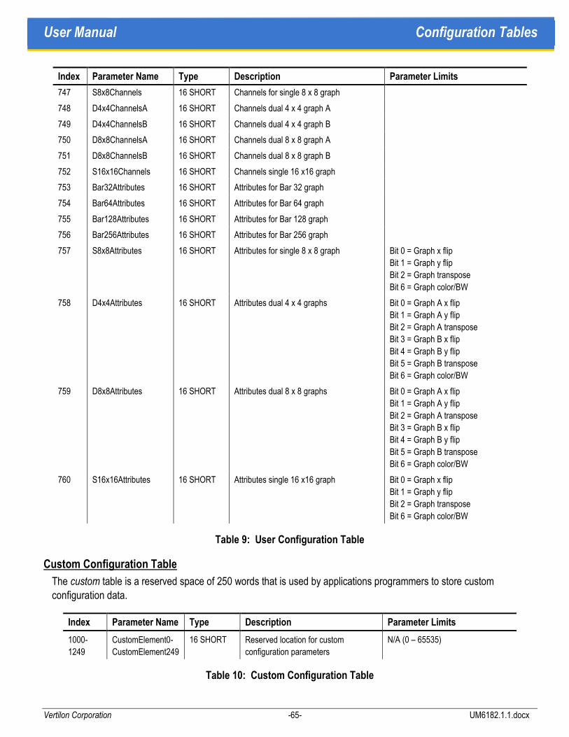
User Manual Configuration Tables
Vertilon Corporation -65- UM6182.1.1.docx
Index Parameter Name Type Description Parameter Limits
747 S8x8Channels 16 SHORT Channels for single 8 x 8 graph
748 D4x4ChannelsA 16 SHORT Channels dual 4 x 4 graph A
749 D4x4ChannelsB 16 SHORT Channels dual 4 x 4 graph B
750 D8x8ChannelsA 16 SHORT Channels dual 8 x 8 graph A
751 D8x8ChannelsB 16 SHORT Channels dual 8 x 8 graph B
752 S16x16Channels 16 SHORT Channels single 16 x16 graph
753 Bar32Attributes 16 SHORT Attributes for Bar 32 graph
754 Bar64Attributes 16 SHORT Attributes for Bar 64 graph
755 Bar128Attributes 16 SHORT Attributes for Bar 128 graph
756 Bar256Attributes 16 SHORT Attributes for Bar 256 graph
757 S8x8Attributes 16 SHORT Attributes for single 8 x 8 graph Bit 0 = Graph x flip
Bit 1 = Graph y flip
Bit 2 = Graph transpose
Bit 6 = Graph color/BW
758 D4x4Attributes 16 SHORT Attributes dual 4 x 4 graphs Bit 0 = Graph A x flip
Bit 1 = Graph A y flip
Bit 2 = Graph A transpose
Bit 3 = Graph B x flip
Bit 4 = Graph B y flip
Bit 5 = Graph B transpose
Bit 6 = Graph color/BW
759 D8x8Attributes 16 SHORT Attributes dual 8 x 8 graphs Bit 0 = Graph A x flip
Bit 1 = Graph A y flip
Bit 2 = Graph A transpose
Bit 3 = Graph B x flip
Bit 4 = Graph B y flip
Bit 5 = Graph B transpose
Bit 6 = Graph color/BW
760 S16x16Attributes 16 SHORT Attributes single 16 x16 graph Bit 0 = Graph x flip
Bit 1 = Graph y flip
Bit 2 = Graph transpose
Bit 6 = Graph color/BW
Table 9: User Configuration Table
Custom Configuration Table
The custom table is a reserved space of 250 words that is used by applications programmers to store custom configuration data.
Index Parameter Name Type Description Parameter Limits
1000-
1249
CustomElement0-
CustomElement249
16 SHORT Reserved location for custom
configuration parameters
N/A (0 – 65535)
Table 10: Custom Configuration Table

DPA201 Two Channel Pulse Analyzer
Vertilon Corporation -66- UM6182.1.1.docx
Factory Configuration Table
Factory-programmed, read-only configuration data is found in the factory table. This table is 750 words long and is described below.
Index Parameter Name Type Description Parameter Limits
1250-
1251
DSPRevCode 32 LONG DSP Revision Code None (0 – 0xFFFFFFFF)
1252-
1253
FPGARevCode 32 LONG FPGA Revision Code None (0 – 0xFFFFFFFF)
1254-
1509
Ch0BckgndOffset-
Ch255BckgndOffset
16 SHORT DSP calculated background for each
channel
0 - 0xFFFF
1510-
1765
Ch0ElecOffset-
Ch255ElecOffset
16 SHORT DSP calculated electrical offsets for
each channel
0 – 0xFFFF
1766-
1767
SiteSerNum 32 LONG Unused None (0 – 0xFFFFFFFF)
1768-
1769
BoardSerNum 32 LONG Board Serial Number None (0 – 0xFFFFFFFF)
1770 SIBSpareControl 16 SHORT Unused Unused
1771 SpeedDyRange 16 SHORT Speed Dynamic Range for each bank,
nibble based
For each nibble (4 bits)
0 = Standard
1 = 16 Bit
2 = 14 Bit
1772 HVPopulated0 16 SHORT High voltage supply 1 populated 0 = Unpopulated
1 = Populated
1773 HVPopulated1 16 SHORT High voltage supply 2 populated 0 = Unpopulated
1 = Populated
1774 BiasVoltage 16 SHORT Bias Voltage Control (DAC 1) 0-4095 (3.0V full scale)
1775 DREVoltage0 16 SHORT Can be configured for an alternative
front-end configuration (DAC4)
0-4095 (3.0V full scale)
1776 RESERVED 16 SHORT Reserved for expansion
1777-
1780
ResetLowThresh0-
ResetLowThresh3
16 SHORT Reset low threshold for
bank 1 to bank 4
0 - 0xFFFF
1781-
1784
ResetHighThresh0-
ResetHighThresh3
16 SHORT Reset high threshold for
bank 1 to bank 4
0 - 0xFFFF
1785-
1788
OORLowThresh0-
OORLowThresh3
16 SHORT Out of range low threshold for
bank 1 to bank 4
0 - 0xFFFF
1789-
1792
OORHighThresh0-
OORHighThresh3
16 SHORT Out of range high threshold for
bank 1 to bank 4
0 - 0xFFFF
1793-
1794
VBTest0- VBTest1 16 SHORT Test voltages (DAC2 and DAC3) 0-4095 (3.0V full scale)
1795-
1798
ChProcessingEnables0
ChProcessingEnables3
16 SHORT Channel processing enables for
bank 1 to bank 4
Bit 0 = Deserializer Enable
Bit 1 = Reset Threshold Enable
Bit 2 = Buffer Enable
Bit 3 = Differencer Raw or Subtract
Bit 4 = Offset Enable

User Manual Configuration Tables
Vertilon Corporation -67- UM6182.1.1.docx
Index Parameter Name Type Description Parameter Limits
Bit 5 = Gain Enable
Bit 6 = Range Adjust Enable
Bit 7 = Data Trigger Enable
0 = Disabled, Raw
1 = Enabled, Subtract
1799-
1802
NumChPopulated0-
NumChPopulated3
16 SHORT Number of channels populated for
bank 1 to bank 4
0- 0xFFFF (Should never exceed 64
channels per bank, 256 total
channels)
1803 SignalPolarity 16 SHORT Signal polarity Nibble-based (4-bits/nibble) per
bank signal polarity select.
0 = Sign Magnitude
1 = Magnitude
1804 TestVoltageEnable 16 SHORT Test voltage enables bank 1 to bank 4 0 = TV1 Disabled, TV2 Disabled
1 = TV1 Enabled, TV2 Disabled
2 = TV1 Disabled, TV2 Enabled
3 = TV1 Enabled, TV2 Enabled
1805-
1806
HV0Parameter0-
HV0Parameter1
16 SHORT High voltage supply 1 normalization
parameters
Factory calculated values. Floating-
point calculation results * 100 are
entered into table.
1807-
1808
HV1Parameter0-
HV1Parameter1
16 SHORT High voltage supply 2 normalization
parameters
Same As Above
1809 AssemblyRevisionPCRev 16 SHORT PCB Revision Number None (0 – 0xFFFF)
1810 AssemblyRevisionLetter 16 SHORT Assembly Revision Letter None (Only letters are A-F)
1811 RESERVED 16 SHORT Reserved for expansion
1812 X1 16 SHORT Trigger Indicator LED On Period 1 – 0x32
1813 Y1 16 SHORT Trigger Indicator LED Off Period 1 – 0x32
1814 X2 16 SHORT Acquisition Indicator LED On Period 1 – 0x32
1815 Y2 16 SHORT Acquisition Indicator LED Off Period 1 – 0x32
1816 CPLDRevCode 16 SHORT CPLD Revision Code 0 – 0xFF
1817 -
1832
ModelNumber 16 SHORT Model Number String None (ASCII Codes)
1833 SDRAMPopulated 16 SHORT SDRAM Type Populated 0: None
1: 32 MByte
2: 64 MByte
1834 SDRAMEnabled 16 SHORT SDRAM Type Enabled 0: None
1: 32 MByte
2: 64 MByte
1836-
1837
ProgScaling0 32 SINGLE Bank 1 floating-point programmable bit
scale factor, units of Coulombs
None
1838-
1839
ProgScaling1 32 SINGLE Bank 2 floating-point programmable bit
scale factor, units of Coulombs
None
1840-
1841
ProgScaling2 32 SINGLE Bank 3 floating-point programmable bit
scale factor, units of Coulombs
None
1842- ProgScaling3 32 SINGLE Bank 4 floating-point programmable bit None

DPA201 Two Channel Pulse Analyzer
Vertilon Corporation -68- UM6182.1.1.docx
Index Parameter Name Type Description Parameter Limits
1843 scale factor, units of Coulombs
1844 -
1999
RESERVED Reserved for expansion
Table 11: Factory Configuration Table
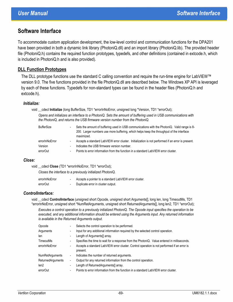
User Manual Software Interface
Vertilon Corporation -69- UM6182.1.1.docx
Software Interface
To accommodate custom application development, the low-level control and communication functions for the DPA201 have been provided in both a dynamic link library (PhotoniQ.dll) and an import library (PhotoniQ.lib). The provided header file (PhotoniQ.h) contains the required function prototypes, typedefs, and other definitions (contained in extcode.h, which is included in PhotoniQ.h and is also provided).
DLL Function Prototypes
The DLL prototype functions use the standard C calling convention and require the run-time engine for LabVIEW™ version 9.0. The five functions provided in the file PhotoniQ.dll are described below. The Windows XP API is leveraged by each of these functions. Typedefs for non-standard types can be found in the header files (PhotoniQ.h and extcode.h).
Initialize:
void __cdecl Initialize (long BufferSize, TD1 *errorInNoError, unsigned long *Version, TD1 *errorOut);
Opens and initializes an interface to a PhotoniQ. Sets the amount of buffering used in USB communications with the PhotoniQ, and returns the USB firmware version number from the PhotoniQ.
BufferSize - Sets the amount of buffering used in USB communications with the PhotoniQ. Valid range is 8-
200. Larger numbers use more buffering, which helps keep the throughput of the interface
maximized.
errorInNoError - Accepts a standard LabVIEW error cluster. Initialization is not performed if an error is present.
Version - Indicates the USB firmware version number.
errorOut - Points to error information from the function in a standard LabVIEW error cluster.
Close:
void __cdecl Close (TD1 *errorInNoError, TD1 *errorOut);
Closes the interface to a previously initialized PhotoniQ.
errorInNoError - Accepts a pointer to a standard LabVIEW error cluster.
errorOut - Duplicate error in cluster output.
ControlInterface:
void __cdecl ControlInterface (unsigned short Opcode, unsigned short Arguments[], long len, long TimeoutMs, TD1 *errorInNoError, unsigned short *NumRetArguments, unsigned short ReturnedArguments[], long len2, TD1 *errorOut);
Executes a control operation to a previously initialized PhotoniQ. The Opcode input specifies the operation to be executed, and any additional information should be entered using the Arguments input. Any returned information is available in the Returned Arguments output.
Opcode - Selects the control operation to be performed.
Arguments - Input for any additional information required by the selected control operation.
len - Length of Arguments[] array.
TimeoutMs - Specifies the time to wait for a response from the PhotoniQ. Value entered in milliseconds.
errorInNoError - Accepts a standard LabVIEW error cluster. Control operation is not performed if an error is
present.
NumRetArguments - Indicates the number of returned arguments.
ReturnedArguments - Output for any returned information from the control operation.
len2 - Length of ReturnedArguments[] array.
errorOut - Points to error information from the function in a standard LabVIEW error cluster.
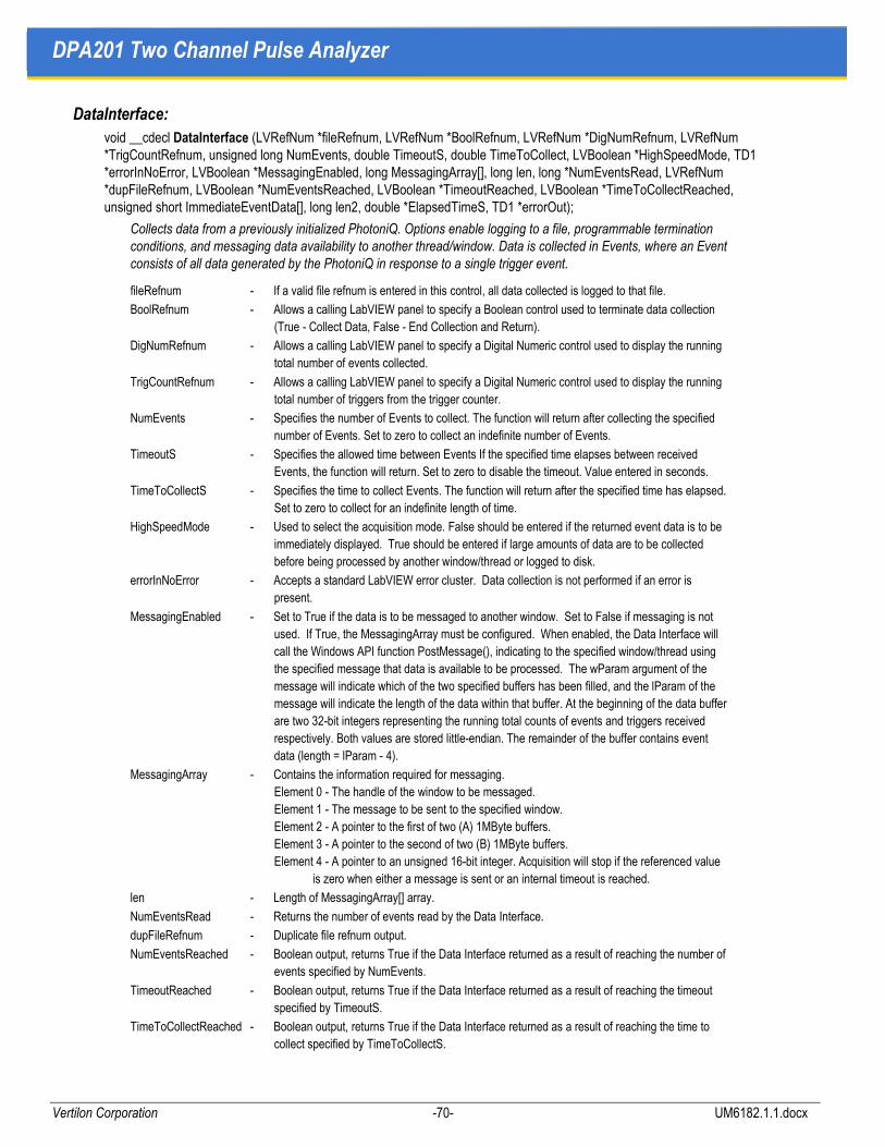
DPA201 Two Channel Pulse Analyzer
Vertilon Corporation -70- UM6182.1.1.docx
DataInterface:
void __cdecl DataInterface (LVRefNum *fileRefnum, LVRefNum *BoolRefnum, LVRefNum *DigNumRefnum, LVRefNum *TrigCountRefnum, unsigned long NumEvents, double TimeoutS, double TimeToCollect, LVBoolean *HighSpeedMode, TD1 *errorInNoError, LVBoolean *MessagingEnabled, long MessagingArray[], long len, long *NumEventsRead, LVRefNum *dupFileRefnum, LVBoolean *NumEventsReached, LVBoolean *TimeoutReached, LVBoolean *TimeToCollectReached, unsigned short ImmediateEventData[], long len2, double *ElapsedTimeS, TD1 *errorOut);
Collects data from a previously initialized PhotoniQ. Options enable logging to a file, programmable termination conditions, and messaging data availability to another thread/window. Data is collected in Events, where an Event consists of all data generated by the PhotoniQ in response to a single trigger event.
fileRefnum - If a valid file refnum is entered in this control, all data collected is logged to that file.
BoolRefnum - Allows a calling LabVIEW panel to specify a Boolean control used to terminate data collection
(True - Collect Data, False - End Collection and Return).
DigNumRefnum - Allows a calling LabVIEW panel to specify a Digital Numeric control used to display the running
total number of events collected.
TrigCountRefnum - Allows a calling LabVIEW panel to specify a Digital Numeric control used to display the running
total number of triggers from the trigger counter.
NumEvents - Specifies the number of Events to collect. The function will return after collecting the specified
number of Events. Set to zero to collect an indefinite number of Events.
TimeoutS - Specifies the allowed time between Events If the specified time elapses between received
Events, the function will return. Set to zero to disable the timeout. Value entered in seconds.
TimeToCollectS - Specifies the time to collect Events. The function will return after the specified time has elapsed.
Set to zero to collect for an indefinite length of time.
HighSpeedMode - Used to select the acquisition mode. False should be entered if the returned event data is to be
immediately displayed. True should be entered if large amounts of data are to be collected
before being processed by another window/thread or logged to disk.
errorInNoError - Accepts a standard LabVIEW error cluster. Data collection is not performed if an error is
present.
MessagingEnabled - Set to True if the data is to be messaged to another window. Set to False if messaging is not
used. If True, the MessagingArray must be configured. When enabled, the Data Interface will
call the Windows API function PostMessage(), indicating to the specified window/thread using
the specified message that data is available to be processed. The wParam argument of the
message will indicate which of the two specified buffers has been filled, and the lParam of the
message will indicate the length of the data within that buffer. At the beginning of the data buffer
are two 32-bit integers representing the running total counts of events and triggers received
respectively. Both values are stored little-endian. The remainder of the buffer contains event
data (length = lParam - 4).
MessagingArray - Contains the information required for messaging.
Element 0 - The handle of the window to be messaged.
Element 1 - The message to be sent to the specified window.
Element 2 - A pointer to the first of two (A) 1MByte buffers.
Element 3 - A pointer to the second of two (B) 1MByte buffers.
Element 4 - A pointer to an unsigned 16-bit integer. Acquisition will stop if the referenced value
is zero when either a message is sent or an internal timeout is reached.
len - Length of MessagingArray[] array.
NumEventsRead - Returns the number of events read by the Data Interface.
dupFileRefnum - Duplicate file refnum output.
NumEventsReached - Boolean output, returns True if the Data Interface returned as a result of reaching the number of
events specified by NumEvents.
TimeoutReached - Boolean output, returns True if the Data Interface returned as a result of reaching the timeout
specified by TimeoutS.
TimeToCollectReached - Boolean output, returns True if the Data Interface returned as a result of reaching the time to
collect specified by TimeToCollectS.

User Manual Software Interface
Vertilon Corporation -71- UM6182.1.1.docx
ImmediateEventData - Returns a portion of the collect Event Data. This output is only guaranteed to be valid when
NumEvents is set to 1 and NumEventsReached is True. The value of this output is unspecified
when the Data Interface returns due to a timeout or a count larger than 1. To evaluate all data,
use file logging or messaging.
len2 - Length of ImmediateEventData[] array.
ElapsedTimeS - Returns the time elapsed while collecting data.
errorOut - Points to error information from the function in a standard LabVIEW error cluster.
ErrorHandler:
void __cdecl ErrorHandler (TD1 *errorInNoError, LVBoolean *OutputErrorResult, char OutputErrorString[], long len, TD1 *errorOut);
Converts a LabVIEW Error Cluster generated by a PhotoniQ function and returns a Boolean Error Result, and an Error String appropriate for display in a user interface.
errorInNoError - Accepts a standard LabVIEW error cluster.
OutputErrorResult - True if an error was present, False if no error.
OutputErrorString - Contains a description of the error present, blank if no error.
len - Length of the OutputErrorString[] array.
errorOut - Duplicate error in cluster output.
LVDLLStatus:
MgErr LVDLLStatus (CStr errStr, int32 errStrLen, void *module);
All Windows DLLs built from LabVIEW, in addition to the functions you export, contain this exported function. The calling program uses this function to verify that the LabVIEW DLL loaded correctly. If an error occurs while loading the DLL, the function returns the error.
errStr - Pass a string buffer to this parameter to receive additional information about the error.
errStrLen - Set to the number of bytes in the string buffer passed as errStr.
module - to retrieve the handle to the LabVIEW Run-Time Engine being used by the DLL. Typically, this
parameter can be set as NULL.
Error Cluster Initialization
The error clusters should be initialized by the user application as shown below:
TD1 errIn = LVFALSE, 0, NULL;
TD1 errOut = LVFALSE, 0, NULL;
This initialization will create the equivalent of a "No Error" cluster for use with the DLL functions. The individual functions will update the errOut cluster if an error is detected during the execution of that function.
Control Interface Commands
The command op codes for the control interface (ControlInterface) are given in the table below.
Opcode Function Name Description
0x03 Update DPA201
Configuration
Updates the DPA201 configuration by writing parameters to the DPA201 User
Configuration Table.
Input Arguments: An unsigned 16-bit number followed by an array of unsigned 16-bit
configuration table parameters. A zero as the first argument indicates a write of the
configuration table to RAM only, while a one indicates a write to flash memory.
Return Arguments: Error returned if necessary

DPA201 Two Channel Pulse Analyzer
Vertilon Corporation -72- UM6182.1.1.docx
Opcode Function Name Description
0x04 Read DPA201
Configuration
Reads the three sections of the DPA201 Configuration Table
Input Arguments: Single unsigned 16-bit number. A zero indicates a read of the
configuration table from RAM, while a one indicates a read from flash memory.
Return Arguments: Array of unsigned 16-bit configuration table parameters.
0x06 Read ADCs Performs a read of the ADCs on the DPA201.
Input Arguments: None.
Return Arguments: Results of eight ADC reads in an array of unsigned 16-bit values
in the following order: HV1 monitor, HV2 monitor, SIB HV Monitor, +3.3VA, +5V UF,
DCRD AIN1, DCRD AIN0, ADC Spare
To convert codes to volts: (Codes/4096)* scale factor. Scale factor = 3 for assembly
rev 0 and rev 1, 5 for assembly rev 2.
0x07 Calibrate Performs a system calibration. Calculates either an offset or background calculation.
(Offset calculation not recommended for users)
Input Arguments: Three unsigned 16-bit arguments. 0x55, 0xAA, and 1 to indicate
offset calculation desired, 2 to indicate background calculation.
Return Arguments: Error if necessary.
0x09 Report Update Increments the number of reports that the PC can accept.
Input Arguments:0x55, 0xAA, and the increment to the number of reports allowed.
Return Arguments: None, this opcode does not generate a response.
0x0B System Mode Changes the system mode from acquire to standby, or standby to acquire.
Input Arguments: 0x55, 0xAA, and the new system mode (0 = standby, 1 = acquire)
Return Arguments: Error if necessary.
0x13 Update SmartSIB
Table
Updates the SmartSIB table (consisting of four ports times four devices by 64
locations) by writing parameters to the DPA201.
Input Arguments: TBD
Return Arguments: TBD
0xAA Re-boot for
FW Update
Reboots the DSP and determines if system should enter the main code or PROM
Burn code. Used for a system firmware update and available when running the main
code or the PROM Burn code.
Input Arguments: 0x55, 0xAA, and 1 to enter PROM Burn code, 0 to enter Main
program code.
Return Arguments: Error if necessary.

User Manual Software Interface
Vertilon Corporation -73- UM6182.1.1.docx
Opcode Function Name Description
0xBB Erase System Code
(PROM Burn)
Erases current DSP or FPGA system code. Available only when running the PROM
Burn code.
Input Arguments: 0x55, 0xAA and 0xF0 for FPGA code, 0x0F for DSP code.
Return Arguments: Error if necessary.
0xCC Program System
Code
(PROM Burn)
Programs one line of DSP or FPGA system code. Available only when running the
PROM Burn code.
Input Arguments: 0x55, 0xAA, 0xF0 (FPGA code) or 0x0F (DSP code), Line from an
Intel Hex-32 formatted programming file.
Return Arguments: Error if necessary.
Table 12: Control Interface Commands
Low Level USB Interface Description
A description of the low level interface to the DPA201 using the USB port is provided for programmers who wish to write their own set of DLLs or drivers. The sections below summarize the details of the interface.
USB Device Defaults
Value Details
USB Compatibility USB 2.0 (High-speed)
Vendor ID 0x0925
Product ID 0x0480
Device ID 0x0000
Class Human Interface Device (HID, 1.1)
Indexed String 1 “Vertilon”
Indexed String 2 “PhotoniQ”
Indexed String 3 “High” (when connected to high-speed host)
“Full” (when connected to full-speed host)
Indexed String 4 “06032801”
Table 13: USB Device Details

DPA201 Two Channel Pulse Analyzer
Vertilon Corporation -74- UM6182.1.1.docx
HID Implementation
The DPA201 implements the reports listed below for communication. Report IDs 0x01, and 0x11 (Feature, Input, and Output) are used to send commands to the DPA201 and receive responses. Report ID 0x22 (Input only) is used to transfer event data from the DPA201 to the host. The opcodes that can be used with each report type are also listed.
Report ID Type Length (Bytes)
Opcodes (Hex)
0x01 Feature 63 00AA
0x11 Output 63 0003, 0004, 0006, 0007, 0009,
000B, 00BB, 00CC
0x11 Input 63 0003, 0004, 0006, 0007, 0009,
000B, 00BB, 00CC
0x22 Input 4095 0099
Table 14: HID Report Descriptions
Report Format (IDs 0x01 and 0x11)
The commands sent to the DPA201 using report IDs 0x01 and 0x11 must have the format specified in the following table. Note that indices here are specified for shortword data.
Index Value
0 Report ID – MSByte must be 0x00
1:3 Fixed Start Codon – ASCII string “CMD”
4 Opcode
5 Length – Number of data words
6:(Length+5) Data
Length+6 Checksum – Sum of all values including checksum equals zero.
Table 15: Report Format (IDs 0x01 and 0x11)

User Manual Software Interface
Vertilon Corporation -75- UM6182.1.1.docx
Responses to commands are returned using the same report ID. Responses have a minimum Length value of 1, so that each response can return an error indicator in the first data location (1 – No Error, 0 – Error). If an error is present, another data word is added to the report in the second data location indicating the specific error. A list of error codes is provided below.
Code Name Description
0x01 Erase Failed DSP or FPGA erase operation failed.
0x02 Program Failed DSP or FPGA program operation failed.
0x77 Configuration ID mismatch Factory configuration ID does not match user value.
0x88 Communication Timeout A control transfer timeout occurred resulting in an incomplete packet.
0xAA Invalid Argument Argument is out of allowed range. Returns an additional data value containing
the index of the offending argument.
0xAB EEPROM Error USB erase or program operation failed.
0xAC EEPROM Bus Busy USB erase or program operation failed.
0xBB Invalid Number of Arguments System received an unexpected number of arguments for a given command.
0xCC Invalid Command System received an unknown command opcode.
0xDD Invalid Length Receive data length does not match expected total length.
0xEE Invalid Start Codon System received an invalid start sequence (“CMD”).
0xFF Invalid Checksum System received an invalid checksum from the host.
Table 16: Report Error Codes
Report Format (ID 0x22)
The event data sent from the DPA201 using report ID 0x22 will have the format specified in the following table. Note that indices here are specified for shortword data. Note that an HID class driver will remove the Report ID before returning any data, and indices should be adjusted accordingly.
Index Value
0 Report ID – MSByte must be 0x00
1:3 Fixed Start Codon – ASCII string “DAT”
4 Opcode – 0x0099
5 Length – Number of data words
6 Number of Events in Report
7 Words per Event
8 Number of Remaining Available Reports
9 Trigger Count (L)
10 Trigger Count (H)
11:(Length+10) Data
Length+11 Checksum – Sum of all values including checksum equals zero.
Table 17: Report Format (ID 0x22)


User Manual Appendix A
Vertilon Corporation -77- UM6182.1.1.docx
Appendix A
Optional High Voltage Supplies (HVPS001 / HVPS002 / HVPS701)
The HVPS series of high voltage power supplies is an upgrade option for the DPA201. Fully controllable through the DPA201 graphical user interface, the HVPS option gives the user the ability to bias photomultiplier tubes, silicon photomultipliers, and avalanche photodiode arrays without the need for additional external equipment. These power supplies are available in a negative 1000 volt version (HVPS001) and negative 1500 volt version (HVPS002) for PMTs, and a negative 100 volt version (HVPS701) for silicon photomultipliers and APDs. All come equipped with a 90 cm cable. The cable includes an industry standard SHV plug on one end of the cable for direct connection to the rear panel of the DPA201. Connection to the sensor is made using a specialized proprietary low-profile connector on the other end.
Description HVPS001 HVPS002 HVPS701
Maximum Unloaded Voltage1 -1000 V -1500 V -100 V
Maximum Fully Loaded Voltage2 -925 V -1390 V -92.5 V
Minimum Voltage -50 V -100 V -5.0 V
Voltage Accuracy ±3% ±3% ±3%
Voltage Adjustment Resolution3 275 mV 410 mV 27.5 mV
Maximum Voltage Ripple at Max Load 0.3% pk-pk 0.5% pk-pk 0.2% pk-pk
Nominal Voltage Ripple Frequency 150 Hz 150 Hz 150 Hz
Maximum Current at Maximum Voltage 370 uA 250 uA 1 mA
Power Consumption at Max Load 0.7 W 0.7 W 0.4 W
Cable Part Number (Included) HVC090 HVC090 HVC090
Cable Length 90 cm 90 cm 90 cm
DPA201 Connector Type4 SHV Plug SHV Plug SHV Plug
Sensor Interface Board Connector Type Proprietary Proprietary Proprietary
1 Voltage limited to Maximum Fully Loaded Voltage in GUI
2 Voltage range divided by three at SIB when using SIB216
3 Voltage adjustment resolution is 100mV in GUI
4 Proprietary connector is miniature low-profile 2-pin
Cable Handling Notice
The included high voltage power supply cables utilize a specialized two pin miniature connector for connection to the sensor interface board and DPA201 printed circuit board (OEM versions only). The connector is designed for low-profile applications such as where a sensor interface board or DPA201 printed circuit board is mounted in a confined space. For this reason care should be taken when connecting and disconnecting the cable. Never disconnect the cable by pulling on the wire. Instead, carefully grip the plastic housing and pull evenly with very light force.


User Manual
Vertilon Corporation -79- UM6182.1.1.docx
Vertilon Corporation has made every attempt to ensure that the information in this document is accurate and complete. Vertilon assumes no liability for errors or for any incidental, consequential, indirect, or special damages including, without limitation, loss of use, loss or alteration of data, delays, lost profits or savings, arising from the use of this document or the product which it accompanies.
Vertilon reserves the right to change this product without prior notice. No responsibility is assumed by Vertilon for any infringements of patents or other rights of third parties which may result from its use. No license is granted by implication or otherwise under the patent and proprietary information rights of Vertilon Corporation.
© 2016 Vertilon Corporation, ALL RIGHTS RESERVED
UM6182.1.1 Sep 2016